Manuale d’uso User guideacc-controls.ru/.../pCOb_programmable_controllers.pdf · programma di...
44
pCO COntrollo programmabile pCO programmable COntroller Manuale d’uso User guide
Transcript of Manuale d’uso User guideacc-controls.ru/.../pCOb_programmable_controllers.pdf · programma di...

pCO COntrollo programmabile pCO programmable COntroller
Manuale d’uso
User guide


Indice1. Introduzione 11.1 Caratteristiche generali 1
2. Architettura hardware 22.1 Codici degli strumenti ed accessori 42.2 pCO Scheda Base - Planimetria 52.3 Significato degli ingressi/uscite 6
3. Il terminale utente 83.1 Versioni del terminale utente 83.2 Tastiera terminale pCO 103.3 Funzionalità e caratteristiche del terminale con display grafico 11
4. Installazione 124.1 Montaggio della scheda-base pCO 124.2 Collegamento degli ingressi 134.3 Collegamento delle uscite 154.4 Alimentazione 154.5 Installazione delle EPROM per la scheda base 154.6 Installazione del terminale utente 164.7 Installazione dell’EPROM di programma del terminale
con display grafico 17
5. Avvertenze per l’installazione 18
6. Rete pLAN 196.1 Indirizzamento scheda base 206.2 Indirizzamento terminali 206.3 Terminali privati / condivisi 216.4 Connessioni elettriche pLAN 226.5 Remotazione terminale con rete pLAN 236.6 Caratteristiche tecniche rete pLAN 236.7 Componenti rete pLAN 23
7. Schede Opzionali 247.1 Scheda per stampante seriale per terminale grafico
PCOSERPRN0 247.2 Stampante seriale per display standard lcd 4x20 o 6 LED 257.3 Scheda seriale per Supervisione e Teleassistenza RS422 257.4 Scheda seriale per Supervisione e Teleassistenza RS485 267.5 Scheda per gestione Modem per il collegamento RS232 267.6 Scheda orologio 277.7 Scheda indirizzamento per rete pLAN 277.8 Scheda indirizzamento, orologio, 32 Kbyte EEPROM 287.9 Scheda per gestione umidificatore OEM 287.10 Installazione schede opzionali 28
8. Ricerca ed eliminazione guasti 29
9. Caratteristiche tecniche 319.1 Caratteristiche tecniche della scheda base PCOB* 319.2 Caratteristiche tecniche del terminale utente PCOI* e PCOT* 339.3 Caratteristiche elettriche 34
10. Dimensioni 3410.1 Terminale utente 3410.2 Tastiera e vetrino 3510.3 Scheda base PCOB* 36
11. Montaggio terminale utente 3711.1 Montaggio a pannello 3711.2 Montaggio a parete 37
12. Connessioni elettriche 38
Contents1. Introduction 11.1 General characteristics 1
2. Hardware structure 22.1 Instrument and accessory codes 42.2 pCO main board - Layout 52.3 Description of the inputs/outputs 6
3. The user terminal 83.1 Versions of the user terminal 83.2 pCO terminal keypad 103.3 Functions and features of the terminal with graphic display 11
4. Installation 124.1 Mounting the pCO main board 124.2 Input connections 134.3 Output connections 154.4 Power 154.5 Installation of the EPROM on the main board 154.6 Installation of the user terminal 164.7 Installation of the program EPROM in terminals
with graphic display 17
5. Warnings for installation 18
6. pLAN network 196.1 Addressing the main board 206.2 Addressing the terminals 206.3 Private / shared terminals 216.4 pLAN electrical connections 226.5 Remote installation of the terminal in a pLAN network 236.6 Technical characteristics of the pLAN network 236.7 Components in the pLAN network 23
7. Optional cards 247.1 Serial printer card for graphic terminal, PCOSERPRN0 247.2 Serial printer for standard 4x20 LCD or 6-LED display 257.3 RS422 serial card for Supervisory and Telemaintenance
networks 257.4 RS485 serial card for Supervisory and Telemaintenance
networks 267.5 Modem interface card for RS232 connection 267.6 Clock card 277.7 Addressing card for pLAN networks 277.8 Addressing, clock, 32Kbyte EEPROM card 287.9 OEM humidifier management card 287.10 Installing the optional cards 28
8. Troubleshooting 29
9. Technical specifications 319.1 Technical specifications of the pCO main board B* 319.2 Technical specifications of the user terminal, PCOI* and PCOT* 339.3 Electrical specifications 34
10. Dimensions 3410.1 User terminal 3410.2 Keypad and window 3510.3 Main board PCOB* 36
11. User Terminal mounting 3711.1 Panel mounting 3711.2 Wall-mounting 37
12. Electrical connections 38

1. IntroduzionepCO è un controllore elettronico programmabile a doppio microproces-sore, sviluppato da CAREL per molteplici applicazioni nel campo delcondizionamento dell’aria e della refrigerazione.La sua completa programmabilità assicura la più assoluta versatilità diapplicazione, consentendo di realizzare prodotti specifici su richiestadel cliente.
1.1 Caratteristiche generaliModelli: pCO è disponibile in diverse versioni. Il terminale può esserepersonalizzato su specifica del cliente. Per esempio è possibile sceglieretra le seguenti caratteristiche:• display a cristalli liquidi (LCD) standard o grafico; display a segmenti
luminosi (LED);• numero di tasti in funzione delle specifiche esigenze di utilizzo;• numero di LED di segnalazione in funzione delle specifiche
esigenze di utilizzo;• policarbonato di protezione della tastiera realizzabile eventualmente
su specifica del cliente.
Programmabilità: pCO CAREL ha la possibilità di essere programmatocon il sistema di sviluppo EasyTools che offre i seguenti vantaggi:• trasportabilità del software su diversi hardware CAREL.
Le applicazioni sviluppate per il pCO possono essere portate semplicemente e velocemente sul Macroplus (e viceversa) adattandosolo gli ingressi e le uscite;
• rapida realizzazione, a un costo competitivo, di programmi personalizzati;
• affidabilità garantita dall’utilizzo di routine standard collaudate “sul campo”.
L’uso di EasyTools, inoltre, offre al cliente la possibilità di garantirsi ilmassimo grado di riservatezza e di autogestione qualora decida di sviluppare programmi ex novo per conto proprio.
La possibilità di utilizzo di uno stesso hardware in applicazioni diversene garantisce la standardizzazione con i noti vantaggi di poter avereprocedure di “test in-circuit”, funzionali e “burn-in” su tutta la produzionee quindi di ottenere un elevato grado di affidabilità a livello globale e disingolo componente elettronico.
Collegamento seriale: è predisposto per il collegamento in rete disupervisione (RS485 e RS422)e in rete pLAN.
Applicazioni: la programmabilità del pCO CAREL assicura la piùassoluta flessibilità di applicazione. Lo stesso hardware standard potràessere dedicato al controllo di:• chiller e pompe calore (programma standard);• roof-top (programma standard);• condizionatori (programma standard);• piccole / medie centrali trattamento aria (a richiesta);• banchi frigo (su specifica);• celle frigorifere (su specifica);• celle di stagionatura (programma standard);• centrali frigorifere (programma standard);• inseritore universale (programma standard).Sono sviluppabili altri tipi di programmi su specifica del cliente.
Omologazioni: la qualità e sicurezza dei controllori della serie pCOsono garantite dal sistema di progettazione e produzione certificatoISO 9001, nonché dal marchio CE.
1. IntroductionThe pCO is a programmable, dual microprocessor electronic control,developed by CAREL for a range of applications in the fields of air-con-ditioning and refrigeration.Being fully programmable it ensures complete applicational versatility,allowing specific products to be created according to customer requests.
1.1 General characteristicsModels: the pCO is available in different versions. The terminal can becustomised according to customer specifications. For example, thecustomer can choose from the following features:• standard or graphic liquid-crystal display (LCD); illuminated segment
display (LED);• number of buttons according to specific user requirements;• number of signal LEDs according to specific user requirements;• polycarbonate keypad cover made according to customer
specifications.
Programmability: the CAREL pCO can be programmed using theEasyTools system, which offers the following advantages:• transfer of the software to different CAREL hardware.
Applications developed for the pCO can be simply and quickly transferred to the Macroplus (and vice-versa), modifying only the inputs and outputs;
• quick development time, at competitive costs, of customised programs;
• reliability guaranteed by the use of field-tested standard routines.
Furthermore, by using EasyTools customers are guaranteed maximumconfidentiality and independence if they decide to develop their ownnew programs.
The possibility to use one set of hardware with different applicationsallows standardisation, with consequent advantages such as the thepossibility to perform functional tests, “test in-circuit”, and “burn-in” onthe every single product and thus achieve extremely high levels of relia-bility, both overall and for each individual electronic component.
Serial connection: the unit is fitted for connection to supervisory(RS485 and RS422) and pLAN networks.
Applications: the fact that the CAREL pCO can be programmed ensu-res complete applicational flexibility. The same standard hardware canthus be used to control:• chillers and heat pumps (standard program);• roof-top units (standard program);• air-conditioners (standard program);• small / medium air handling systems (according to specifications);• showcases (according to specifications);• cold rooms (according to specifications);• maturing rooms (standard program);• compressor packs (standard program);• stage controllers (standard program).Other types of programs can be developed according to customer spe-cifications.
Certification: the quality and safety of the pCO series control are gua-ranteed by Carel’s ISO 9001-certified design and production system,as well as the CE mark.
1

2. Architettura hardware
L’architettura del pCO CAREL prevede:• una scheda base a microprocessore dedicata all’esecuzione del
programma di regolazione, dotata del set di morsetti necessari alla connessione verso i dispositivi controllati (ad esempio: valvole, compressori, ventilatori). Il programma è scritto su EPROM mentre i parametri impostati sono memorizzati in modo permanente su EEPROM, consentendo il loro mantenimento anche in caso di mancanza di alimentazione (senza bisogno di una batteria di mantenimento).La scheda base permette anche la connessione alla rete locale pLAN (pCO Local Area Network) costituita da più schede base e piùterminali. Ogni scheda può scambiare informazioni (qualsiasi variabile, digitale o analogica, a seconda del programma applicativo)con velocità di trasmissione elevata. Possono essere collegate fino a16 unità in modo da condividere le informazioni in tempi molto brevi.Il collegamento verso la linea seriale di supervisione/teleassistenza secondo lo standard RS422 o RS485, viene realizzato tramite le schede seriali opzionali (PCOSER****) e il protocollo di comunicazione CAREL.
• un terminale, sempre gestito da microprocessore, dotato di display, tastiera e LED per rendere possibile la programmazione dei parametri di controllo (set-point, banda differenziale, soglie di allarme)e le operazioni fondamentali da parte dell’utente (On/Off, visualizzazione dei valori controllati, stampa opzionale).La connessione del terminale alla scheda base non è necessaria per il funzionamento a regime del controllore, ma può essere utilizzata solo per la programmazione iniziale dei parametri fondamentali.
Grazie alle potenzialità del programma applicativo, il terminale utenteconsente:• la programmazione iniziale della macchina con accesso protetto
da password per garantirne la sicurezza;• la possibilità di modificare in qualsiasi momento i parametri
fondamentali di funzionamento opzionalmente protetti da password;• la visualizzazione tramite display degli allarmi rilevati e la loro
segnalazione acustica per mezzo di un cicalino;• la visualizzazione tramite LED delle funzioni attive;• la visualizzazione di tutte le grandezze misurate;• l’eventuale stampa degli allarmi ricevuti e la stampa periodica dello
stato delle variabili principali della macchina (opzionale);• la possibilità di simulare tasti “funzione” dalla tastiera standard con
indicazione a LED se la funzione è stata selezionata (dipende dal programma applicativo);
• la possibilità di simulare una tastiera numerica dalla tastiera standardper l’impostazione dei dati (dipende dal programma applicativo).
2. Hardware structure
The CAREL pCO hardware features:• a microprocessor-controlled MAIN Board dedicated to the execution
of the control program, fitted with a set of terminals for connection tothe controlled devices (for example: valves, compressors, fans).The program is written in the EPROM while the set parameters are stored permanently in the EEPROM, meaning they are protected even in the case of black-outs (without needing a back-up battery).The main board is also fitted for connection to a pLAN network (pCOLocal Area Network) made up of a number of main boards and terminals. Each board can exchange information (any variable, digital or analogue, according to the application program) at high speed. Up to 16 units can be connected and share information at thesame time. Connection to the serial line of the supervisory/telemaintenance network using the RS422 or RS485 standard is performed using the optional serial cards (PCOSER****) and the CAREL communication protocol.
• a terminal, also microprocessor-controlled, fitted with a display, keypad and LEDs to allow the control parameters (set-point, differential band, alarm thresholds) to be programmed and basic user operations (on/off, display of the controlled values, optional print-out). Connection of the terminal to the main board is not necessary for normal control operations, but rather is used for the initial programming of the fundamental parameters.
Thanks to the powerful application program, the terminal can be used for:
• the initial programming of the machine with password-protected access to ensure security;
• modifying, at any time, the fundamental operating parameters, whichcan be password-protected if required;
• displaying the detected alarms, as well as signalling them acoustically via buzzer;
• displaying the active functions on the LEDs;• displaying all measured values;• printing, if required, the detected alarms, as well as periodically
printing the status of the main machine variables (optional);• simulating the “function” buttons on the standard keypad with
indication via LED if the function has been selected (depending on the application program);
• simulating a numeric keypad on the standard keypad for setting the data (depending on the application program).
2

Architettura Hardware
L’architettura hardware è così definita:1. Terminale utente con tastiera, display e LED di segnalazione.2. Scheda Base con microprocessore, EPROM con il programma
applicativo, morsetti ingresso/uscita.3. Cavo di collegamento tra terminale e scheda base.4. Cavo di collegamento tra terminale e stampante seriale
(a cura del cliente).5. Stampante seriale (a cura del cliente).6. Cavo AWG20/22 per connessione in pLAN tra più schede pCO.
Hardware Structure
The hardware structure is the following:1. User terminal with keypad, display and signal LEDs.2. Main board with microprocessor, EPROM containing the
application program, input/output terminals.3. Cable for connecting the terminal and the main board.4. Cable for connecting the terminal and a serial printer
(supplied by the customer).5. Serial printer (supplied by the customer).6. AWG20/22 cable for pLAN connection between a number
of pCO boards
3
on/off alarm enter
pCO Terminal
menu I/O set prog.
?info
GraphicRoom 1
Temp
on/off enteralarm
J1J2
J3J4
J5J6J2
4J2
2J2
1J2
0J1
7J1
1
J11
To Terminal (PCOT*, PCOI*)
J19
GNDRX/TX-RX/TX+
1
5
2
4
3
6
Figura 1 Architettura hardware pCOFigure 1 pCO hardware structure
2.1 Codici degli strumenti ed accessori
pCO scheda base
pCO terminale utente
Cavi di collegamento
Schede Opzionali
2.1 Instrument and accessory codes
pCO main board
pCO user terminal
Connection cables
Optional cards
4
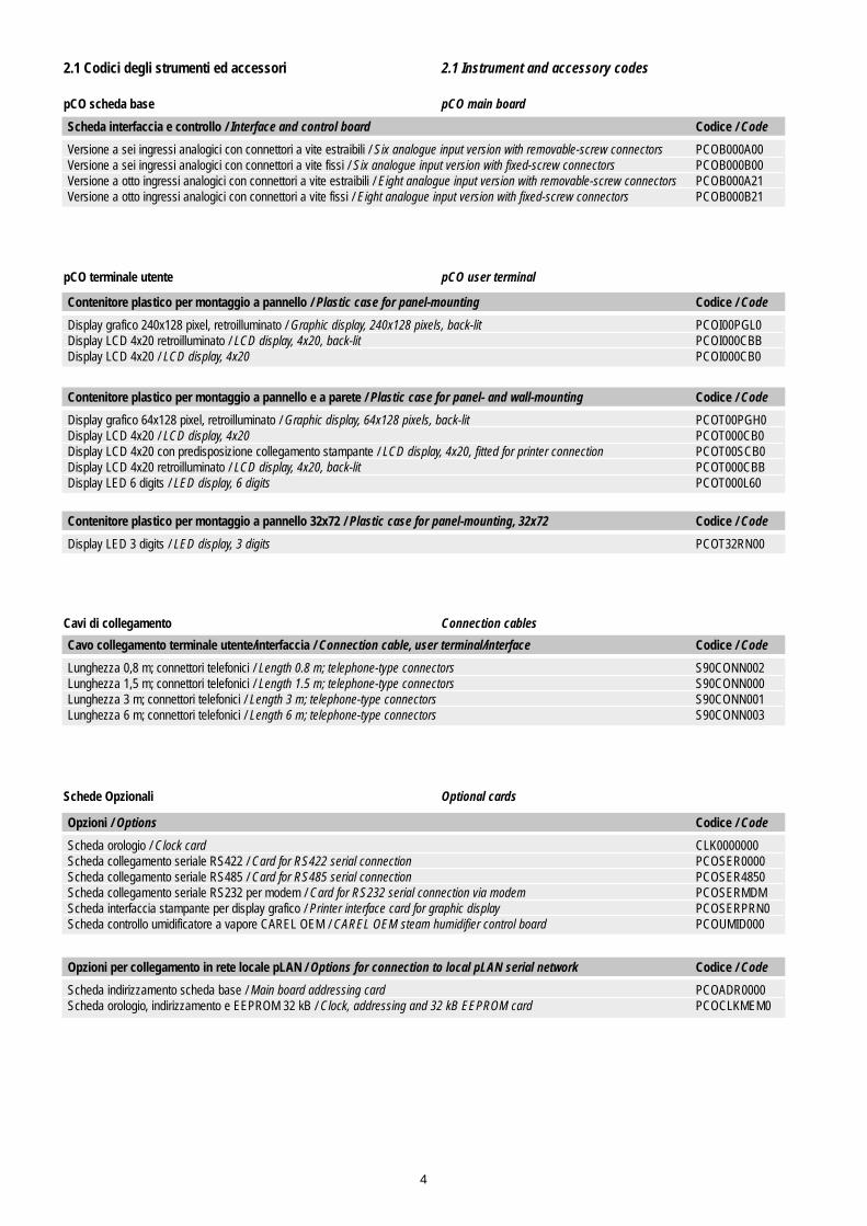
Scheda interfaccia e controllo / Interface and control board Codice / Code
Versione a sei ingressi analogici con connettori a vite estraibili / Six analogue input version with removable-screw connectors PCOB000A00Versione a sei ingressi analogici con connettori a vite fissi / Six analogue input version with fixed-screw connectors PCOB000B00Versione a otto ingressi analogici con connettori a vite estraibili / Eight analogue input version with removable-screw connectors PCOB000A21Versione a otto ingressi analogici con connettori a vite fissi / Eight analogue input version with fixed-screw connectors PCOB000B21
Contenitore plastico per montaggio a pannello / Plastic case for panel-mounting Codice / Code
Display grafico 240x128 pixel, retroilluminato / Graphic display, 240x128 pixels, back-lit PCOI00PGL0Display LCD 4x20 retroilluminato / LCD display, 4x20, back-lit PCOI000CBBDisplay LCD 4x20 / LCD display, 4x20 PCOI000CB0
Contenitore plastico per montaggio a pannello e a parete / Plastic case for panel- and wall-mounting Codice / Code
Display grafico 64x128 pixel, retroilluminato / Graphic display, 64x128 pixels, back-lit PCOT00PGH0Display LCD 4x20 / LCD display, 4x20 PCOT000CB0Display LCD 4x20 con predisposizione collegamento stampante / LCD display, 4x20, fitted for printer connection PCOT00SCB0Display LCD 4x20 retroilluminato / LCD display, 4x20, back-lit PCOT000CBBDisplay LED 6 digits / LED display, 6 digits PCOT000L60
Contenitore plastico per montaggio a pannello 32x72 / Plastic case for panel-mounting, 32x72 Codice / Code
Display LED 3 digits / LED display, 3 digits PCOT32RN00
Cavo collegamento terminale utente/interfaccia / Connection cable, user terminal/interface Codice / Code
Lunghezza 0,8 m; connettori telefonici / Length 0.8 m; telephone-type connectors S90CONN002Lunghezza 1,5 m; connettori telefonici / Length 1.5 m; telephone-type connectors S90CONN000Lunghezza 3 m; connettori telefonici / Length 3 m; telephone-type connectors S90CONN001Lunghezza 6 m; connettori telefonici / Length 6 m; telephone-type connectors S90CONN003
Opzioni / Options Codice / Code
Scheda orologio / Clock card CLK0000000Scheda collegamento seriale RS422 / Card for RS422 serial connection PCOSER0000Scheda collegamento seriale RS485 / Card for RS485 serial connection PCOSER4850Scheda collegamento seriale RS232 per modem / Card for RS232 serial connection via modem PCOSERMDMScheda interfaccia stampante per display grafico / Printer interface card for graphic display PCOSERPRN0Scheda controllo umidificatore a vapore CAREL OEM / CAREL OEM steam humidifier control board PCOUMID000
Opzioni per collegamento in rete locale pLAN / Options for connection to local pLAN serial network Codice / Code
Scheda indirizzamento scheda base / Main board addressing card PCOADR0000Scheda orologio, indirizzamento e EEPROM 32 kB / Clock, addressing and 32 kB EEPROM card PCOCLKMEM0
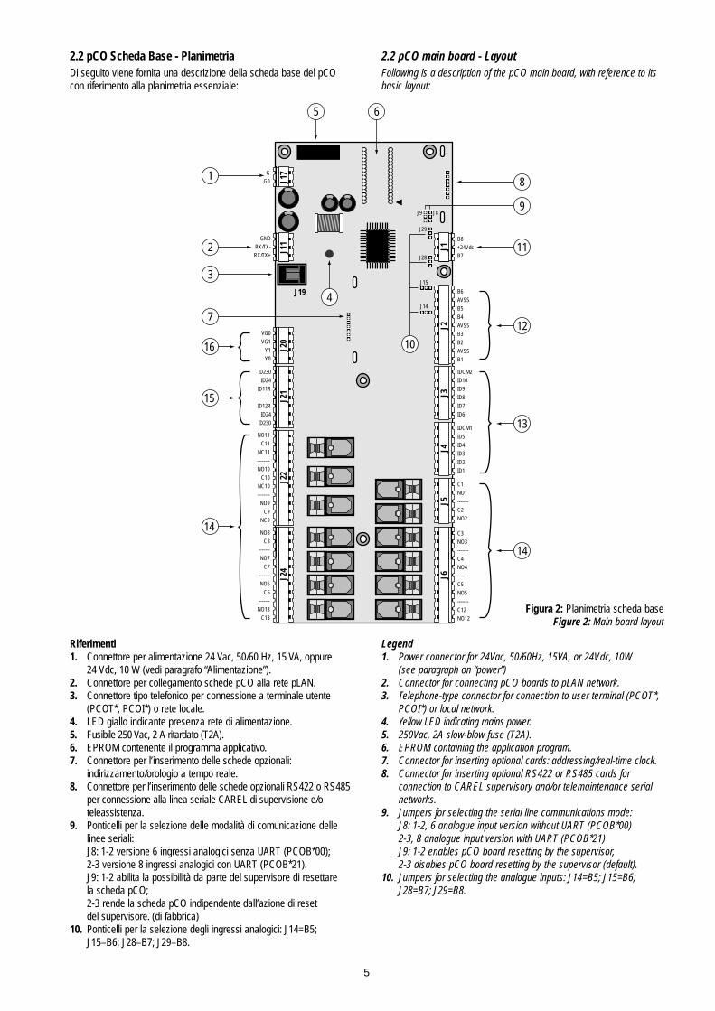
2.2 pCO Scheda Base - PlanimetriaDi seguito viene fornita una descrizione della scheda base del pCOcon riferimento alla planimetria essenziale:
Riferimenti1. Connettore per alimentazione 24 Vac, 50/60 Hz, 15 VA, oppure
24 Vdc, 10 W (vedi paragrafo “Alimentazione”).2. Connettore per collegamento schede pCO alla rete pLAN.3. Connettore tipo telefonico per connessione a terminale utente
(PCOT*, PCOI*) o rete locale.4. LED giallo indicante presenza rete di alimentazione.5. Fusibile 250 Vac, 2 A ritardato (T2A).6. EPROM contenente il programma applicativo.7. Connettore per l’inserimento delle schede opzionali:
indirizzamento/orologio a tempo reale.8. Connettore per l’inserimento delle schede opzionali RS422 o RS485
per connessione alla linea seriale CAREL di supervisione e/o teleassistenza.
9. Ponticelli per la selezione delle modalità di comunicazione delle linee seriali:J8: 1-2 versione 6 ingressi analogici senza UART (PCOB*00);2-3 versione 8 ingressi analogici con UART (PCOB*21).J9: 1-2 abilita la possibilità da parte del supervisore di resettare la scheda pCO;2-3 rende la scheda pCO indipendente dall’azione di reset del supervisore. (di fabbrica)
10. Ponticelli per la selezione degli ingressi analogici: J14=B5;J15=B6; J28=B7; J29=B8.
2.2 pCO main board - LayoutFollowing is a description of the pCO main board, with reference to itsbasic layout:
Legend1. Power connector for 24Vac, 50/60Hz, 15VA, or 24Vdc, 10W
(see paragraph on “power”)2. Connector for connecting pCO boards to pLAN network.3. Telephone-type connector for connection to user terminal (PCOT*,
PCOI*) or local network.4. Yellow LED indicating mains power.5. 250Vac, 2A slow-blow fuse (T2A).6. EPROM containing the application program.7. Connector for inserting optional cards: addressing/real-time clock.8. Connector for inserting optional RS422 or RS485 cards for
connection to CAREL supervisory and/or telemaintenance serial networks.
9. Jumpers for selecting the serial line communications mode:J8: 1-2, 6 analogue input version without UART (PCOB*00)2-3, 8 analogue input version with UART (PCOB*21)J9: 1-2 enables pCO board resetting by the supervisor,2-3 disables pCO board resetting by the supervisor (default).
10. Jumpers for selecting the analogue inputs: J14=B5; J15=B6;J28=B7; J29=B8.
5
J17
J11
J20
J21
J22
J24
J1J2
J3J4
J5J6
B8+24VdcB7
B6
AVSS
B5
B4
AVSS
B3
B2
AVSS
B1
IDCM2
ID10
ID9
ID8
ID7
ID6
IDCM1
ID5
ID4
ID3
ID2
ID1
C1
NO1
-------
C2
NO2
C3
NO3
-------
C4
NO4
-------
C5
NO5
-------
C12
NO12
NO8
C8
-------
NO7
C7
-------
NO6
C6
-------
NO13
C13
NO11
C11
NC11
--------
NO10
C10
NC10
--------
NO9
C9
NC9
ID230
ID24
ID11R
--------
ID12R
ID24
ID230
VG0
VG1
Y1
Y0
GNDRX/TX-RX/TX+
GG0
J19
J14
J15
J28
J29
J9 J8
1
2
3
16
15
14
14
13
12
5
4
11
9
10
7
6
8
Figura 2: Planimetria scheda baseFigure 2: Main board layout

Riferimenti (Figura 2: Planimetria scheda base)
11. Ingressi analogici addizionali B7 e B8 (solo su schede a 8 ingressi analogici) selezionabili per segnali 0÷1 Vdc o 4÷20 mA (di fabbrica);+24 Vdc (80 mA) utilizzabile per l’alimentazione di max 4 sonde.
12. Ingressi analogici: B(n): Ingressi analogici 1÷6;AVSS: riferimento comune degli ingressi analogici B(n).Gli ingressi da B1 a B4 accettano sonde NTC CAREL. B5 e B6 accettano sonde con un segnale di 0÷1 Vdc o 4÷20mA (di fabbrica).
13. Ingressi digitali a 24 Vac/Vdc: ID(n): Ingressi digitali 1÷10;IDCM1: Riferimento comune per ingressi digitali 1÷5;(positivo con alimentazione continua 24 Vdc)IDCM2: Riferimento comune per ingressi digitali 6÷10.(positivo con alimentazione continua 24 Vdc)
14. Uscite digitali (potenza commutabile 2500 VA, 10 A/250 Vac):NO(n): Contatto normalmente aperto uscita (n);NC(n): Contatto norm. chiuso uscita (n); (solo per le uscite 9, 10, 11)C(n): Contatto comune per il contatto uscita (n).
15. Ingressi digitali disponibili a 230 Vac o 24Vac/Vdc (10 mA):ID230 Vac: Ingressi digitali 11 e 12 per segnali a 230 Vac;ID24 Vac: Ingressi digitali 11 e 12 per segnali a 24 Vac/Vdc;ID11R, ID12R: riferimento comune per, rispettivamente, ingressi digitali ID11 e ID12. Evitare nel modo più assoluto di portare segnali a 230 Vac sul morsetto per 24 Vac/Vdc, pena danneggiamentodella scheda stessa.
16. Uscite analogiche 0÷10 Vdc: Y(n): Uscite analogiche 1 e 2, 10 mA max;VG1: Aliment. esterna per uscite analogiche (24 Vac o 24 Vdc);VG0: Riferimento per l’alimentazione e per il segnale delle uscite analogiche Y0 e Y1.
2.3 Significato degli ingressi/uscite
Legend (Figure 2: Main board layout)
11. Additional analogue inputs B7 and B8 (only on boards with 8 analogue inputs) can be selected for 0÷1Vdc or 4÷20mA (default) signals; +24Vdc (80mA) can be used to power a max. of 4 probes.
12. Analogue inputs:B(n): Analogue inputs 1÷6AVSS: common reference for the analogue inputs B(n).Inputs from B1 to B4 accept CAREL NTC probes. B5 and B6 can be selected for probes with 0÷1Vdc or 4÷20mA (default) signals.
13. 24Vac/Vdc digital inputs: ID(n): Digital inputs 1÷10;IDCM1: Common reference for digital inputs 1÷5; (positive for 24Vdc power)IDCM2: Common reference for digital inputs 6÷10. (positive for 24Vdc power)
14. Digital outputs (commutable power 2500VA, 10 A/250Vac):NO(n): Normally-open output contact (n);NC(n): Normally-closed output contact (n); (only for outputs 9, 10, 11)C(n): Common contact for output contact (n).
15. Digital inputs available for 230Vac or 24Vac/Vdc (10 mA):ID230Vac: Digital inputs 11 and 12 for 230Vac signals;ID24Vac: Digital inputs 11 and 12 for 24Vac/Vdc signals;ID11R, ID12R: common reference for, respectively, digital inputs ID11 and ID12. To avoid damaging the board do not, in any circum-stances, connect 230Vac signals to the 24Vac/Vdc terminal.
16. Analogue outputs, 0÷10Vdc:Y(n): Analogue outputs 1 and 2, 10mA max;VG1: External power for analogue outputs (24Vac or 24Vdc);VG0: Power and signal reference for analogue outputs Y0 and Y1.
2.3 Description of the inputs/outputs
6
Connettore / Connector Segnali / Signals Descrizione / Description
J17 G Alimentazione +24 Vdc, 10 W o 24 Vac, 50/60 Hz, 15 VA Power ,+24Vdc, 10W or 24Vac, 50/60Hz, 15VA
J17 G0 Riferimento alimentazione / Power referenceJ11 GND, RX-/TX-, RX+/TX+ Connettore per collegamento a rete pLAN / Connector for connection to pLAN networkJ19 Terminale Connettore per cavo telefonico a 6 vie del terminale
Terminal Connector for 6-way telephone-type cable to the terminalJ20 VG0 Alimentazione per uscita analogica optoisolata 0 Vac
Power for optically-insulated 0 Vac analogue outputJ20 VG1 Alim. per uscita analogica optoisolata 24 Vac/Vdc
Power for optically-insulated 24Vac/Vdc analogue outputJ20 Y1 Uscita analogica 2 / Analogue output 2J20 Y0 Uscita analogica 1 / Analogue output 1J21 ID230 Vac Ingresso digitale 11 a 230 Vac / Digital input 11, 230VacJ21 ID24 Vac Ingresso digitale 11 a 24 Vac/Vdc / Digital input 11, 24Vac/VdcJ21 ID11R Comune per ingresso digitale 11 / Common for digital input 11J21 ——— Non connesso / Not connectedJ21 ID12R Comune per ingresso digitale 12 / Common for digital input 12J21 ID24 Vac Ingresso digitale 12 a 24 Vac/Vdc / Digital input 12 a 24Vac/VdcJ21 ID230 Vac Ingresso digitale 12 a 230 Vac / Digital input 12 a 230VacJ22 NO-11 Contatto normalmente aperto relè 11 / Normally-open contact relay 11J22 C-11 Comune relè 11 / Common relay 11J22 NC-11 Contatto normalmente chiuso relè 11 / Normally-closed contact relay 11J22 ——— Non connesso / Not connectedJ22 NO-10 Contatto normalmente aperto relè 10 / Normally-open contact relay 10J22 C10 Comune relè 10 / Common relay 10J22 NC-10 Contatto normalmente chiuso relè 10 / Normally-closed contact relay 10J22 ——— Non connesso / Not connectedJ22 NO-9 Contatto normalmente aperto relè 9 / Normally-open contact relay 9J22 C9 Comune relè 9 / Common relay 9J22 NC-9 Contatto normalmente chiuso relè 9 / Normally-closed contact relay 9J24 NO-8 Contatto normalmente aperto relè 8 / Normally-open contact relay 8J24 C8 Comune relè 8 / Common relay 8J24 ——— Non connesso / Not connected

7
Connettore / Connector Segnali / Signals Descrizione / Description
J24 NO-7 Contatto normalmente aperto relè 7 / Normally-open contact relay 7J24 C7 Comune relè 7 / Common relay 7J24 ——— Non connesso / Not connectedJ24 NO-6 Contatto normalmente aperto relè 6 / Normally-open contact relay 6J24 C6 Comune relè 6 / Common relay 6J24 ——— Non connesso / Not connectedJ24 NO-13 Contatto normalmente aperto relè 13 / Normally-open contact relay 13J24 C13 Comune relè 13 / Common relay 13J6 NO-12 Contatto normalmente aperto relè 12 / Normally-open contact relay 12J6 C12 Comune relè 12 / Common relay 12J6 ——— Non connesso / Not connectedJ6 NO-5 Contatto normalmente aperto relè 5 / Normally-open contact relay 5J6 C5 Comune relè 5 / Common relay 5J6 ——— Non connesso / Not connectedJ6 NO-4 Contatto normalmente aperto relè 4 / Normally-open contact relay 4J6 C4 Comune relè 4 / Common relay 4J6 ——— Non connesso / Not connectedJ6 NO-3 Contatto normalmente aperto relè 3 / Normally-open contact relay 3J6 C3 Comune relè 3 / Common relay 3J5 NO-2 Contatto normalmente aperto relè 2 / Normally-open contact relay 2J5 C2 Comune relè 2 / Common relay 2J5 ——— Non connesso / Not connectedJ5 NO-1 Contatto normalmente aperto relè 1 / Normally-open contact relay 1J5 C1 Comune relè 1 / Common relay 1J4 ID1 Ingresso digitale 1 / Digital input 1J4 ID2 Ingresso digitale 2 / Digital input 2J4 ID3 Ingresso digitale 3 / Digital input 3J4 ID4 Ingresso digitale 4 / Digital input 4J4 ID5 Ingresso digitale 5 / Digital input 5J4 IDCM1 Comune ingressi digitali ID1-ID5 / Common, digital inputs ID1-ID5J3 ID6 Ingresso digitale 6 / Digital input 6J3 ID7 Ingresso digitale 7 / Digital input 7J3 ID8 Ingresso digitale 8 / Digital input 8J3 ID9 Ingresso digitale 9 / Digital input 9J3 ID10 Ingresso digitale 10 / Digital input 10J3 IDCM2 Comune ingressi digitali ID6-ID10 / Common, digital inputs ID6-ID10J2 B1 Ingresso analogico 1 (solo sonda NTC) / Analogue input 1 (NTC probes only)J2 AVSS Comune ingressi analogici / Common analogue inputsJ2 B2 Ingresso analogico 2 (solo sonda NTC) / Analogue input 2 (NTC probes only)J2 B3 Ingresso analogico 3 (solo sonda NTC) / Analogue input 3 (NTC probes only)J2 AVSS Comune ingressi analogici / Common analogue inputsJ2 B4 Ingresso analogico 4 (solo sonda NTC) / Analogue input 4 (NTC probes only)J2 B5 Ingresso analogico 5 (sonda attiva 0÷1 V o 4÷20 mA)
Analogue input 5 (0÷1V or 4÷20mA active probe)J2 AVSS Comune ingressi analogici / Common analogue inputsJ2 B6 Ingresso analogico 6 (sonda attiva 0÷1V o 4÷20 mA)
Analogue input 6 (0÷1V or 4÷20mA active probe)J1 B7 Ingresso analogico 7 disponibile solo su scheda a 8 ingressi analogici (sonda attiva 0÷1V o 4÷20 mA)
Analogue input 7 available only on boards with 8 analogue inputs (0÷1V or 4÷20 mA active probe)J1 +24 Vdc Alimentazione per sonde attive esterne 24 Vdc (corrente max. erogabile 80 mA)
Power for 24Vdc external active probe (max. current 80mA)J1 B8 Ingresso analogico 8 disponibile solo su scheda a 8 ingressi analogici (sonda attiva 0÷1V o 4÷20 mA)
Analogue input 8 available only on boards with 8 analogue inputs (0÷1V or 4÷20mA active probe)
Tabella 1: significato ingressi usciteTable 1: Description of inputs and outputs

3. Il terminale utente
3.1 Versioni del terminale utenteIl terminale utente viene utilizzato solo per la programmazione deiparametri della macchina. I modelli con display LCD 4x20 sono dotatidi potenziometro per la regolazione del contrasto del display.Il potenziometro è raggiungibile con un cacciavite a lama piana attraverso il relativo foro localizzato nell’angolo in alto a destra delcoperchio posteriore (modelli PCOT*) oppure asportando il coperchioposteriore (modelli PCOI*); in questo caso il potenziometro è localizzatonell’angolo in alto a destra della scheda base stessa. I modelli condisplay grafico permettono la regolazione del contrasto premendosimultaneamente i tasti Menù e oppure Menù e .
Display LCD 4X20 montaggio a parete o pannello (PCOT00*CB*)
Caratteristiche• numero righe: 4• numero colonne: 20• altezza carattere: 5 mm
Sono disponibili inoltre:• Versione predisposta per collegamento
con una stampante seriale (PCOT00SCB0)• Versione con LCD retroilluminato
(PCOT000CBB)
Display LED montaggio a parete o pannello (PCOT000L60)
Caratteristiche• numero cifre: 6• colore: verde• altezza: 13 mm• numero LED indicatori laterali: 5• numero LED indicatori della funzione
visualizzata sul display: 3+3
Display LCD grafico montaggio a parete o pannello (PCOT00PGH0)
Caratteristiche• LCD:128x64 pixel, grafico, retroilluminato• righe: 8• colonne: 16
Display a 3 cifre LED 32x72 (PCOT32RN00)
Caratteristiche• 3 cifre LED• 4 tasti
3.The user terminal
3.1 Versions of the user terminalThe user terminal is used only for programming the machine parameters. The models with a 4x20 LCD display are fitted with a trimmer for adjusting the contrast of the display. The trimmer can beaccessed using a flat-head screwdriver through the hole located in top-right corner of the rear cover (models PCOT*) or by removing therear cover (models PCOI*); in the latter case the trimmer is located onthe top-right corner of the main board itself. For models with graphicdisplay the contrast con be adjusted by simultaneously pressing theMenu and or Menu and buttons.
4x20 LCD for wall- or panel-mounting (PCOT00*CB*)
Features• number of rows: 4• number of columns: 20• font height: 5mm
Other features available:• Version fitted for connection to a serial
printer (PCOT00SCB0)• Version with back-lit LCD (PCOT000CBB)
LED display for wall- or panel-mounting (PCOT000L60)
Features• number of digits: 6• colour: green• height: 13 mm• number of side indicator LEDs: 5• number of function indicator LEDs
on the display: 3+3
Graphic LCD for wall- or panel-mounting (PCOT00PGH0)
Features• LCD:128x64 pixels, graphic, back-lit• rows: 8• columns: 16
3-digit LED display, 32x72 (PCOT32RN00)
Features• 3-digit LED• 4 buttons
8
on/off enteralarm
Fig. 3
on/off enteralarm
A____
Parem
Psw
B____
Val
AL
1_ __________
2_ __________
3_ __________
4_ __________
5_ __________
Fig. 4
GraphicRoom 1
Temp
on/off enteralarm
Fig. 5
PRGmute
SEL
Fig. 6

Display LCD 4x20 montaggio a pannello (PCOI000CB*)
Caratteristiche:• numero righe: 4• numero colonne: 20• altezza carattere: 5 mm
È disponibile inoltre:• Versione con LCD retroilluminato
(PCOI000CBB)
Display LCD grafico montaggio a pannello (PCOI00PGL0)
Caratteristiche• LCD: 240x128 pixel, grafico,
retroilluminato• righe: 16• colonne: 30
4x20 LCD for panel-mounting (PCOI000CB*)
Features:• number of rows: 4• number of columns: 20• font height: 5mm
Other features available:• Version with back-lit LCD
(PCOI000CBB)
Graphic LCD for panel-mounting (PCOI00PGL0)
Features• LCD: 240x128 pixels, graphic, back-lit• rows: 16• columns: 30
9
on/off alarm enter
pCO Terminal
menu I/O set prog.
?info
Fig. 7
menu I/O set prog.
?info
on/off alarm enter
pCO Graphic
Fig. 8

3.2 Tastiera terminale pCO
Riferimenti1. Tasti meccanici coperti
da policarbonato2. LED indicatori funzione3. Policarbonato adesivo
eventualmente personalizzabile4. Tasti in gomma siliconica
Utilizzo tipico dei tasti nelle applicazioni standard Carel
visualizza i valori rilevati dalle sonde
visualizza i valori relativi alla manutenzione dei dispositivi (ore di utilizzo del dispositivo e reset contaore di funzionamento)
accede al gruppo di maschere per la gestione della stampante (ove prevista)
visualizza lo stato degli ingressi e delle uscite, sia digitali che analogiche
permette la visualizzazione/programmazione dell’orologio (se presente)
consente l’impostazione dei set points
consente l’impostazione dei vari parametri di funzionamento (protezioni, soglie)
+ premendo assieme questi tasti si entra nella configura-zione della macchina (numero di dispositivi collegati al pCO, programmazione dei fondo scala e calibrazione sonde, ecc.)
visualizza la versione del programma applicativo ed altre informazioni
I LED a fianco di ciascun tasto si illuminano quando la relativa funzioneè attivata (a seconda del programma applicativo).
Tasti esterni in gomma siliconica (versione standard)
Riferimenti Figura 10 (relativi a programmi applicati-vi standard Carel):1. tasto on-off: consente l’accensione e lo spegnimento
della macchina. Il LED verde che illumina il tasto indica se l’accensione è stata effettuata.
2. tasto alarm: è utilizzato per la visualizzazione su display degli allarmi, per il loro ripristino manuale e per la tacitazione del cicalino. Se il tasto è illuminato (colore rosso)significa che è stato rilevato almeno un allarme.
3. frecce verso l’alto per la gestione delle maschere su display e per l’impostazione dei valori dei parametri di controllo (non retroilluminato).
4. frecce verso il basso per la gestione delle maschere su display e perl’impostazione dei valori dei param. di controllo (non retroilluminato).
5. tasto enter: per la conferma dei dati impostati.Il tasto è sempre retroilluminato (luce gialla) per indicare la presenza dell’alimentazione.
?info
prog.menu
prog.
set
I/O
menu
3.2 pCO terminal keypad
Legend1. Mechanical buttons protected
by polycarbonate cover2. Function indicator LEDs 3. Customisable polycarbonate
label4. Silicon rubber buttons
Typical use of the buttons in standard Carel applications
displays the values measured by the probes
displays the values relating to the maintenance of the devices (device operating hours and operating hour counter reset)
accesses the group of screens for printer management (where included)
displays the status of the inputs and the outputs, both digital and analogue
allows the display/programming of the clock (if present)
stores the set points
allows the various operating parameters to be set (safety parameters, thresholds)
+ pressing these buttons at the same time accesses the machine configuration mode (number of devices connected to the pCO, scale setting and probe calibration, etc.)
displays the version of the application program and other information
The LEDs next to each button are illuminated when the relative func-tion is active (depending on the application program).
External silicon rubber buttons (standard version)
Figure 10 legend (relating to standard Carel application programs):1. on-off button: switches the machine on or off. The
green LED illuminates the button to indicate that themachine is on.
2. alarm button: used for displaying or manually resetting the alarms and for silencing the buzzer. If the button is illuminated (red) at least one alarm has been detected.
3. up arrow: used for managing the currently displayed screen or for setting values of the control parameters (not back-lit).
4. down arrow: used for managing the currently displayed screen or for setting values of the control parameters (not back-lit).
5. enter button: used for confirming the set data. The button is constantly back-lit (yellow), indicating the presence of mains power.
?info
prog.menu
prog.
set
I/O
menu
10
on/off enteralarm
A____
Parem
Psw
B____
Val
AL
1_ __________
2_ __________
3_ __________
4_ __________
5_ __________
2
1
3
menu
?info
I/O set prog.
4 Fig. 9
on/off enteralarm
1 2 3 4 5
Fig. 10
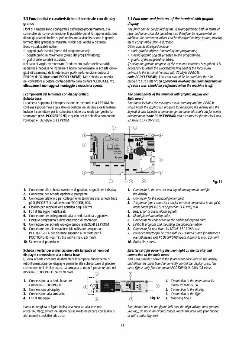
3.3 Funzionalità e caratteristiche del terminale con displaygraficoI font di caratteri sono configurabili dall’utente-programmatore, siacome stile sia come dimensione. È possibile quindi la rappresentazionedi tutti gli alfabeti. Inoltre si può realizzare la visualizzazione in grandeformato delle grandezze misurate, visibili così anche a distanza.Sono visualizzabili inoltre:• oggetti grafici statici (creati dal programmatore);• oggetti grafici in movimento (creati dal programmatore);• grafici delle variabili acquisite.Nel caso si voglia memorizzare l’andamento grafico delle variabiliacquisite è necessario installare a bordo del terminale la scheda orolo-gio/indirizzamento della rete locale pLAN nella versione dotata diEPROM da 32 kbyte (cod. PCOCLKMEM0). Tale scheda va inseritanel connettore a pettine contraddistinto dalla dicitura “CLOCK/MEM”;effettuarne il montaggio/smontaggio a macchina spenta.
I componenti del terminale con dispay grafico:Scheda base La scheda supporta il microprocessore, le memorie e la EPROM checontiene il programma applicativo di gestione del display e della tastiera.Include il connettore per la schedina seriale opzionale per gestire lastampante (cod. PCOSERPRN0) e quello per la schedina contenentel’orologio e i 32 kByte di EEPROM.
1. Connettore alla scheda inverter e di gestione segnali per il display.2. Connettore per scheda opzionale stampante.3. Connettore telefonico per collegamento terminale alla scheda base
pCO (PCOB*21) o al derivatore TCONN6J000.4. Cicalino per segnalazione acustica degli allarmi.5. Fori di fissaggio metallizzati.6. Connettore per collegamento alla scheda tastiera aggiuntiva.7. EPROM programma e direzione/verso di montaggio.8. Connettore per scheda orologio tempo reale/32kB EEPROM.9. Connettore per alimentazione (da utilizzare sempre con
PCOI00PGL0 e per distanze superiori a 50 metri per il PCOT00PGH0) (da min. 0,5 mm2 a max. 2,5 mm2).
10. Schermo di protezione
Scheda inverter per alimentazione della lampada al neon deldisplay e connessione alla scheda baseQuesta scheda consente di alimentare la lampada fluorescente diretro-illuminazione del display e permette alla scheda base di pilotarecorrettamente il display usato. La lampada al neon è presente solo nelmodello PCOI00PGLO 240x128 pixel.
1. Connessione a scheda base per il modello PCOI00PGL0.
2. Connessione al display.3. Connessione alla lampada.4. Fori di fissaggio.
L’area tratteggiata in figura indica una zona ad alta tensione (circa 360 Vac); evitare nel modo più assoluto di toccare con le dita oaltri utensili conduttivi tale zona.
3.3 Functions and features of the terminal with graphicdisplayThe fonts can be configured by the user-programmer, both in terms ofstyle and dimension. All alphabets can therefore be represented. Inaddition, the measured values can be displayed in large format, makingthem easily visible from a distance.Other objects displayed include:• static graphic objects (created by the programmer).• moving graphic objects (created by the programmer).• graphs of the acquired variables.If saving the graphic progress of the acquired variables is required, it isnecessary to install the clock/addressing card of the local pLANnetwork in the terminal (version with 32 kbyte EPROM, code PCOCLKMEM0). This card should be inserted into the slotmarked “CLOCK/MEM”; all operations involving the mounting/removalof such cards should be performed when the machine is off.
The components of the terminal with graphic display are:Main board The board includes the microprocessor, memory and the EPROMwhich holds the application program for managing the display and thekeypad. It also includes a connector for the optional serial card for printermanagement (code PCOSERPRN0) and a connector for the clock and32 kbyte EEPROM card.
1. Connector to the inverter and signal management card for the display.
2. Connector for the optional printer card.3. Telephone-type connector card for terminal connection to the pCO
main board (PCOB*21) or junction TCONN6J000.4. Buzzer for acoustic alarm signals.5. Metal-plated mounting holes.6. Connector for connection to the additional keypad card.7. EPROM program and mounting direction/orientation.8. Connector for real-time clock/32kB EEPROM card.9. Power connector (to be used with PCOI00PGL0 and for distances
over 50 metres with PCOT00PGH0) (from. 0.5mm2 to max. 2.5mm2).10. Protective screen
Inverter card for powering the neon light on the display and connection to the main boardThis card provides power to the fluorescent back-light on the displayand allows the main board to correctly control the display used. Theneon light is only fitted on model PCOI00PGLO, 240x128 pixels.
1. Connection to the main board for model PCOI00PGL0.
2. Connection to the display.3. Connection to the light.4. Mounting holes.
The shaded area in the figure indicates the high-voltage area (around360Vac); do not in an circumstances touch this area with your fingersor with conducting tools.
11
1
5
5
5
5
2
10 4 3 6
8
97
Fig. 11
F.1.
ERG INCPS-E1715
9549E
1nK400
RB59H3
3
2
1
4
4
4
Fig. 12

Scheda schermo (opzione per stampante)Per tutti i modelli del terminale grafico pCO esiste la possibilità di inse-rire una scheda opzionale per la gestione di una stampante seriale, nelconnettore a pettine contrassegnato dal numero 2 indicato in Figura 1.Per fare ciò occorre prima asportare la scheda di protezione localizzatanell’area riservata alla scheda stampante opzionale. La funzione èquella di aumentare l’immunità ai disturbi del terminale; il relativo fis-saggio si effettua mediante tre viti da avvitare nei tre fori individuati dalnumero 1 nella figura seguente.
1. Fori di fissaggio.2. Tacca di riferimento delpin 1 della EPROM e relati-va serigrafia a bordo scheda.
4 Installazione
4.1 Montaggio della scheda-base pCOIl PCOB* va installato su un pannello metallico di spessore 0,5÷2 mmtramite gli appositi distanziali. La scheda va normalmente montata aquadro, ma le sue particolari dimensioni meccaniche fanno sì che siaanche possibile il montaggio su guida DIN, utilizzando gli appositimoduli in commercio.Avvertenze. Sicurezza per gli operatori e precauzioni nel maneggiare la/e scheda/e.Per tutelare la sicurezza degli operatori e la salvaguardia della scheda,prima di effettuare qualsiasi intervento sulla scheda togliere l'alimentazione dalla stessa.I danneggiamenti elettrici che si verificano sui componenti elettroniciavvengono quasi sempre a causa delle scariche elettrostatiche indottedall’operatore. È quindi necessario prendere adeguati accorgimenti perqueste categorie di componenti, ed in particolare:• prima di maneggiare qualsiasi componente elettronico o scheda,
toccare una messa a terra (il fatto stesso di evitare di toccare non èsufficiente in quanto una scarica di 10.000 V, tensione molto facileda raggiungere con l’elettricità statica, innesca un arco di circa 1 cm);
• i materiali devono rimanere per quanto possibile all’interno delle loroconfezioni originali. Se è necessario prelevare la scheda base dauna confezione trasferire il prodotto in un imballo antistatico senzatoccare il retro della scheda con le mani;
• evitare nel modo più assoluto di utilizzare sacchetti in plastica, polistirolo o spugne non antistatiche;
• evitare nel modo più assoluto il passaggio diretto tra operatori (per evitare fenomeni di induzione elettrostatica e conseguenti scariche).
Protective screen (optional printer card)For all pCO graphic terminal models an optional card can be added formanaging a serial printer; this is inserted in the slot marked by thenumber 2 in Figure 1. To insert the card first remove the protectivescreen which is found in the area reserved for the optional printer card.The function of the screen is to increase the terminal’s immunity todisturbances; mounting is performed by tightening the three screws inthe three holes marked by the number 1 in the following figure.
1. Mounting holes.2. Reference slot for pin 1
of the EPROM and relativemarkings on the board.
4 Installation
4.1 Mounting the pCO main boardThe PCOB* should be installed on a metal panel, between 0.5 and 2mm thick, using the special spacers. The board is normally mounted inthe electrical panel, yet its specific dimensions mean that it can also bemounted on DIN rails, using the relative modules available on themarket.Warning. Safety information.Before any servicing on the card, disconnect the power supply from thecard in order to safeguard the personnel against injury and the carditself against damages.Electrical damage on electronic components usually occurs because ofelectrostatic discharges caused by the operator.Therefore, when handling these components, you must refer to the following:• before using any electronic component or card, touch a grounding
(it is not sufficient not to touch, because a 10,000V discharge, a very easy voltage value to reach with static electricity, produces an electric arc of about 1cm);
• the components must be kept inside their original package as long as possible. If necessary, take the main board from a package and put it into an antistatic package without touching the back of the board with your hands;
• absolutely avoid non-antistatic plastic bags or spongee and polystyrene;
• do not hand in the card directly to other among operators (to avoid any electrostatic induction and discharges).
12
1 2Fig. 13
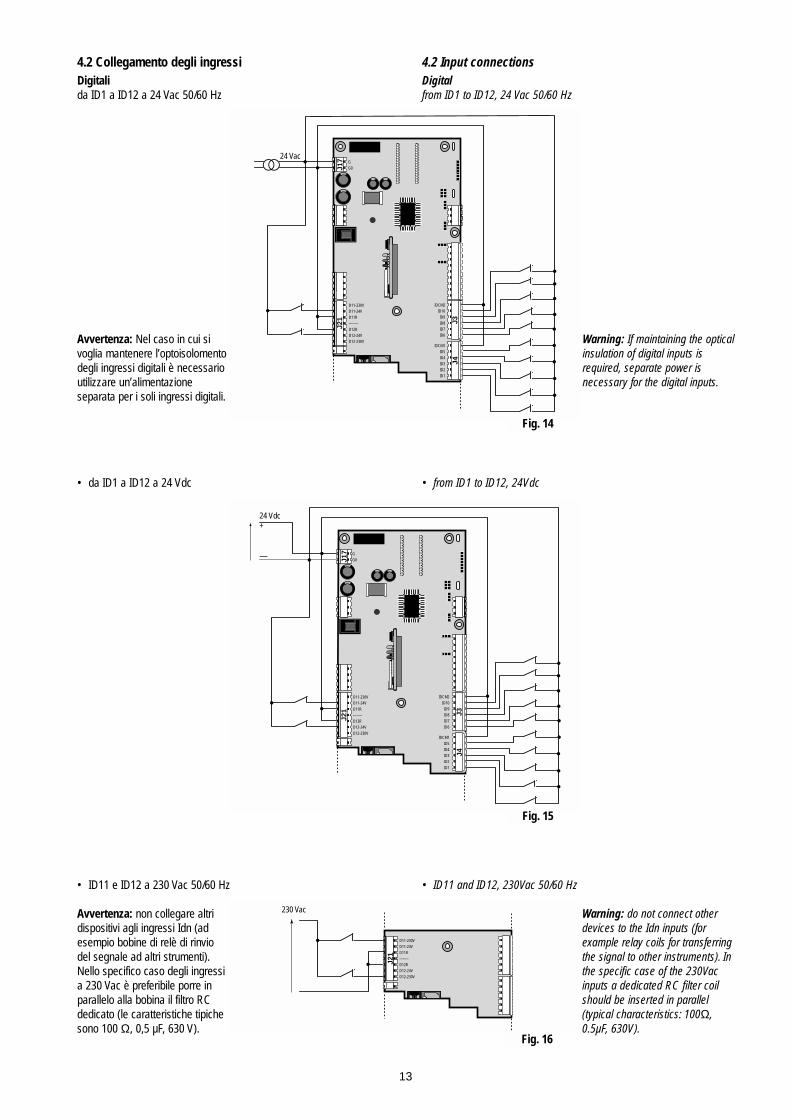
4.2 Collegamento degli ingressiDigitalida ID1 a ID12 a 24 Vac 50/60 Hz
Avvertenza: Nel caso in cui sivoglia mantenere l’optoisolomentodegli ingressi digitali è necessarioutilizzare un’alimentazione separata per i soli ingressi digitali.
• da ID1 a ID12 a 24 Vdc
• ID11 e ID12 a 230 Vac 50/60 Hz
Avvertenza: non collegare altridispositivi agli ingressi Idn (adesempio bobine di relè di rinviodel segnale ad altri strumenti).Nello specifico caso degli ingressia 230 Vac è preferibile porre inparallelo alla bobina il filtro RCdedicato (le caratteristiche tipichesono 100 Ω, 0,5 µF, 630 V).
4.2 Input connections Digitalfrom ID1 to ID12, 24 Vac 50/60 Hz
Warning: If maintaining the opticalinsulation of digital inputs is required, separate power isnecessary for the digital inputs.
• from ID1 to ID12, 24Vdc
• ID11 and ID12, 230Vac 50/60 Hz
Warning: do not connect otherdevices to the Idn inputs (forexample relay coils for transferringthe signal to other instruments). Inthe specific case of the 230Vacinputs a dedicated RC filter coilshould be inserted in parallel (typical characteristics: 100Ω,0.5µF, 630V).
13
J3J4
J21
J17 G
G0
D11-230VD11-24VD11R--------D12RD12-24VD12-230V
IDCM2ID10ID9ID8ID7ID6
IDCM1ID5ID4ID3ID2ID1
24 Vac
J3J4
J21
J17 G
G0
D11-230VD11-24VD11R--------D12RD12-24VD12-230V
IDCM2ID10ID9ID8ID7ID6
IDCM1ID5ID4ID3ID2ID1
24 Vdc+
—
J21
D11-230VD11-24VD11R--------D12RD12-24VD12-230V
230 Vac
Fig. 14
Fig. 15
Fig. 16

Analogici• da B1 a B4 per sonde NTC CAREL• B5 e B6 per sonde attive in tensione (0÷1 Vdc) o corrente (4÷20 mA)
selezionabili da jumper• B7 e B8 per sonde attive in tensione (0÷1 Vdc) o corrente (4÷20 mA)
selezionabili da jumper - solo sulle schede ad 8 ingressi analogici (PCOB000*21).
Avvertenza: la possibilità di utilizzare gli ingressi sonda in modalità4÷20 mA o 0÷1 V, dipende dall’applicativo in uso.
Configurazione degli ingressi analogici B5, B6, B7 e B8
Fare riferimento alla seguente figura per eseguirela corretta predisposizione:• J14 si riferisce all’ingresso B5• J15 si riferisce all’ingresso B6• J28 si riferisce all’ingresso B7• J29 si riferisce all’ingresso B8
Posizione 1-2:Ingresso analogico predisposto in 4/20 mAPosizione 2-3:Ingresso analogico predisposto in 0/1 V
Avvertenza: La configurazione di default è 1-2
Tipologia delle sonde collegabili agli ingressi analogici
• Sonde di temperatura ed umidità (Codice AS********)
• Sonde di temperatura NTC universali (2 fili)
I due cavi delle sonde NTC sono equivalenti in quanto non hanno pola-rità. Pertanto non è necessario rispettare un ordine particolare nel col-legamento alla morsettiera.
• Sonde di pressione (2 fili)
Analogue• from B1 to B4 for CAREL NTC probes• B5 and B6 for active voltage (0÷1Vdc) or current (4÷20mA)
probes, selected by the jumper• B7 and B8 for active voltage (0÷1Vdc) or current (4÷20 mA) probes,
selected by the jumper - only on boards with 8 analogue inputs (PCOB000*21).
Warning: you can use the input probe with 4÷20mA or 0÷1V mode,depending on the application in use.
Configuration of the analogue inputs B5, B6, B7 and B8
Refer to the following figure for correct configuration:• J14 refers to input B5• J15 refers to input B6• J28 refers to input B7• J29 refers to input B8
Position 1-2:Analogue input set for 4/20 mAPosition 2-3:Analogue input set for 0/1 V
Warning: The default configuration is 1-2
Types of probes which can be connected to the analogue inputs
• Temperature and Humidity probes (Code AS********)
• Temperature NTC universal probes (2 wires)
The two wires of the NTC probes are the same, in that they have nopolarity. It is not therefore necessary to follow any special order whenconnecting them to the terminal block.
• Pressure probe (2 wires)
14
3 2 1
3 2 1
321
321
J9 J8
J29(B8)
J28(B7)
J14(B5)
J15(B6)
J1J2
+ (G)ntcntcMout H
pCO Sonda / Probe
Bn= 1, ... , 4
Bn= 5, ... , 8
Bm= 5, ..., 8
AVSS
+24 Vdc
ntc = uscita NTC (res.) della sonda probe (res.) NTC output
out T = uscita attiva di temperatura temperature active output
out H = uscita attiva di umidità humidity active output
M = riferimento/ground
+ (G) = alimentazione/power supply
B7
+24V
dc
B8
B6
AVSS
B5
B4
AVSS
B3
B2
AVSS
B1
La calza va collegata a AVSSThe shield must be connected to AVSS Fig. 18
Fig. 17
B7
+24V
dc
B8
B6
AVSS
B5
B4
AVSS
B3
B2
AVSS
B1
A
B
pCO Sonda / Probe
Bn= 1, ... , 4
AVSS
ntc = uscita NTC della sondaprobe NTC output
M = riferimento / ground
A=cap. plasticoA=plastic cap
NTC008HP00NTC015HP00NTC030HP00NTC060HP00
B=cap. metallicoB=inox steel cap
NTC008WP00NTC015WP00NTC030WP00NTC060WP00
Lunghez.Lenght
0.8m1.5m3.0m6.0m
Fig. 19
B7
+24V
dc
B8
B6
AVSS
B5
B4
AVSS
B3
B2
AVSS
B1
A
B
A=con. maschioA=male con.
SPK1000000SPK2500000SPK3000000
B=con. femminaB=female con.
SPK4000001SPK5000001SPK6000001
Range
-0,5÷7 bar0÷25 bar0÷30 bar
pCO Sonda / Probe
Bn= 5, ... , 8
+24 Vdc
Filo bianco = uscita attiva di press.White wire = Pressure active output Filo marrone = alimentazioneBrow wire = power supply
Fig. 20
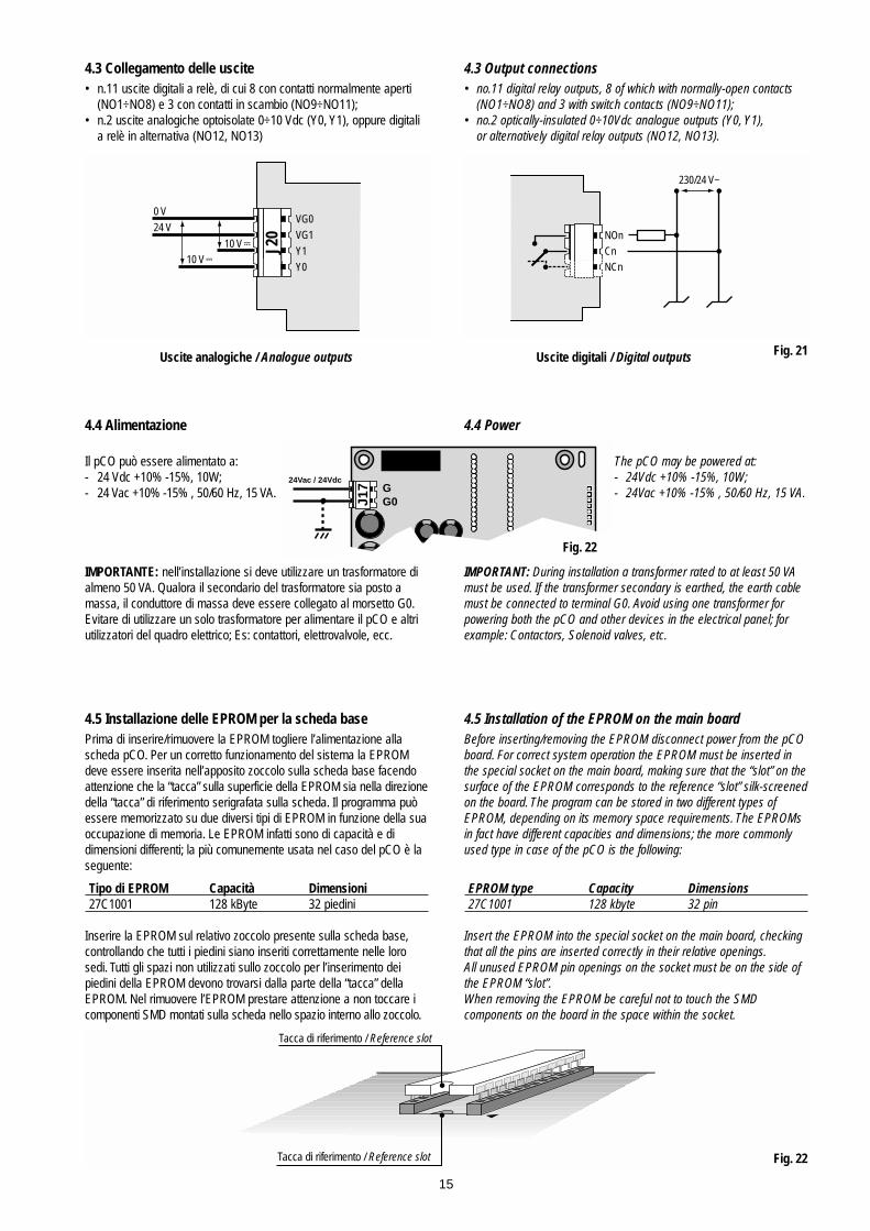
4.3 Collegamento delle uscite• n.11 uscite digitali a relè, di cui 8 con contatti normalmente aperti
(NO1÷NO8) e 3 con contatti in scambio (NO9÷NO11);• n.2 uscite analogiche optoisolate 0÷10 Vdc (Y0, Y1), oppure digitali
a relè in alternativa (NO12, NO13)
Uscite analogiche / Analogue outputs
4.4 Alimentazione
Il pCO può essere alimentato a:- 24 Vdc +10% -15%, 10W;- 24 Vac +10% -15% , 50/60 Hz, 15 VA.
IMPORTANTE: nell’installazione si deve utilizzare un trasformatore dialmeno 50 VA. Qualora il secondario del trasformatore sia posto amassa, il conduttore di massa deve essere collegato al morsetto G0.Evitare di utilizzare un solo trasformatore per alimentare il pCO e altriutilizzatori del quadro elettrico; Es: contattori, elettrovalvole, ecc.
4.5 Installazione delle EPROM per la scheda basePrima di inserire/rimuovere la EPROM togliere l’alimentazione allascheda pCO. Per un corretto funzionamento del sistema la EPROMdeve essere inserita nell’apposito zoccolo sulla scheda base facendoattenzione che la “tacca” sulla superficie della EPROM sia nella direzionedella “tacca” di riferimento serigrafata sulla scheda. Il programma puòessere memorizzato su due diversi tipi di EPROM in funzione della suaoccupazione di memoria. Le EPROM infatti sono di capacità e didimensioni differenti; la più comunemente usata nel caso del pCO è laseguente:
Tipo di EPROM Capacità Dimensioni27C1001 128 kByte 32 piedini
Inserire la EPROM sul relativo zoccolo presente sulla scheda base,controllando che tutti i piedini siano inseriti correttamente nelle lorosedi. Tutti gli spazi non utilizzati sullo zoccolo per l’inserimento dei piedini della EPROM devono trovarsi dalla parte della “tacca” dellaEPROM. Nel rimuovere l’EPROM prestare attenzione a non toccare icomponenti SMD montati sulla scheda nello spazio interno allo zoccolo.
4.3 Output connections • no.11 digital relay outputs, 8 of which with normally-open contacts
(NO1÷NO8) and 3 with switch contacts (NO9÷NO11);• no.2 optically-insulated 0÷10Vdc analogue outputs (Y0, Y1),
or alternatively digital relay outputs (NO12, NO13).
Uscite digitali / Digital outputs
4.4 Power
The pCO may be powered at:- 24Vdc +10% -15%, 10W;- 24Vac +10% -15% , 50/60 Hz, 15 VA.
IMPORTANT: During installation a transformer rated to at least 50 VAmust be used. If the transformer secondary is earthed, the earth cablemust be connected to terminal G0. Avoid using one transformer forpowering both the pCO and other devices in the electrical panel; forexample: Contactors, Solenoid valves, etc.
4.5 Installation of the EPROM on the main boardBefore inserting/removing the EPROM disconnect power from the pCOboard. For correct system operation the EPROM must be inserted inthe special socket on the main board, making sure that the “slot” on thesurface of the EPROM corresponds to the reference “slot” silk-screenedon the board. The program can be stored in two different types ofEPROM, depending on its memory space requirements. The EPROMsin fact have different capacities and dimensions; the more commonlyused type in case of the pCO is the following:
EPROM type Capacity Dimensions27C1001 128 kbyte 32 pin
Insert the EPROM into the special socket on the main board, checkingthat all the pins are inserted correctly in their relative openings.All unused EPROM pin openings on the socket must be on the side ofthe EPROM “slot”.When removing the EPROM be careful not to touch the SMD components on the board in the space within the socket.
15
J20
VG0
VG1
Y1
Y0
0 V
24 V
10 V10 V
NOnCnNCn
230/24 V~
Fig. 21
GG0J1
7
24Vac / 24Vdc
Tacca di riferimento / Reference slot
Tacca di riferimento / Reference slot
Fig. 22
Fig. 22

4.6 Installazione del terminale utenteLa connessione tra terminale utente e scheda base viene effettuatatramite cavo telefonico a 6 vie fornito da CAREL.
Per effettuare il collegamento basta inserire il connettore telefonico nelmorsetto J19 della scheda base e nel morsetto B del terminale. Inserirea fondo il connettore nel morsetto finché non scatta il serraggio.Per estrarre il connettore basta premere leggermente sul fermo in plastica sporgente e sfilare il cavo.
La scheda base può funzionare anche senza terminale; non scollega-re e poi ricollegare il terminale alla scheda base senza aver attesocirca 5 secondi (qualora l’operazione venga eseguita a macchinaaccesa).
Installazione dei terminali da parete/pannello (cod. PCOT00****):Questo tipo di terminale è stato disegnato per il montaggio a pannelloe a parete. La dima di foratura, nel caso di montaggio a pannello, deveavere le dimensioni di 167x108 mm.Per l’installazione fare attenzione alle seguenti istruzioni:• svitare le due viti poste sul coperchio posteriore del terminale
e sfilare il coperchio;• appoggiare il frontale sulla parte anteriore del pannello;• inserire il coperchio dalla parte posteriore facendo coincidere i due
fori con i due prigionieri posizionati nel coperchio frontale;• riavvitare le viti.Lo spessore massimo del pannello è di 6 mm. Effettuare quindi i previ-sti collegamento elettrici. Il montaggio a parete prevede l’utilizzo del-l’apposita staffa di fissaggio e di una scatola da parete standard a 3moduli per interruttori al fine di consentire il passaggio dei cavi. Fissarela staffa alla parete, utilizzando la vite; effettuare infine i previsti colle-gamenti elettrici ed incastrare il dorso dello strumento alla staffa.
Collegamenti elettriciCollegare il cavo telefonico (cod. S90CONN00*) proveniente dallascheda di potenza (cod. PCOB*) nell’apposita presa. Il modello condisplay grafico (cod. PCOT00OGH0) è provvisto di un’ulteriore morset-tiera a vite.
4.6 Installation of the user terminalThe connection between the user terminal and main board is madeusing a 6-way telephone-type cable supplied by CAREL.
To make the connection simply insert the telephone-type connector interminal J19 on the main board and in terminal B in the user terminal.Fully insert the connector into the terminal until the lock snaps intoplace. To remove the connector press lightly on the protruding plasticstop and pull out the cable.
The main board can also function without the terminal; do not discon-nect and then re-connect the terminal to the main board withoutfirst waiting around 5 seconds (if the operations are performed whilethe machine is on).
Wall/panel mounting of the terminal (code PCOT00****):This type of terminal has been designed for panel- and wall-mounting.The drilling template, in the case of panel-mounting, must have dimen-sions of 167x108 mm.During installation carefully note the following instructions :• unscrew the two screws on the rear cover of the terminal and
remove the cover;• rest the front cover on the rear part of the panel;• insert the rear cover, making sure the two holes correspond
to the two screw studs on the front cover;• tighten the screws.The maximum panel thickness allowed is 6 mm. Perform the requiredelectrical connections. Wall-mounting requires the use of a specialmounting bracket and a standard 3-module switchbox in order to allowthe passage of the cables. Fasten the bracket to the wall , using thescrews; finally, perform the required electrical connections and clip therear of the instrument onto the bracket.
Electrical connectionsConnect the telephone-type cable (code S90CONN00*) from the powerboard (code PCOB*) into the relative socket. The model with graphicdisplay (code PCOT00OGH0) is fitted with an extra screw-in terminalblock.
16
cavocable
terminaleterminal
scheda basemain board
B
J19
Fig. 24

Installazione dei terminali da pannello (cod. PCOI00****):Questi terminali sono stati studiati per il montaggio a pannello; la dimadi foratura deve avere le dimensioni di 173x154 mm. Per l’installazioneseguire le istruzioni riportate di seguito:• asportare la cornice estetica a scatto;• inserire la parte plastica contenente display e schede elettroniche
sulla parete forata anteriore del pannello, facendo attenzione che la guarnizione sul lembo inferiore del frontale sia bene in appoggio conla parte anteriore del pannello;
• praticare sul pannello 4 fori del diametro di 2,5 mm in corrispondenzaesatta con i fori presenti sullo strumento;
• inserire le viti di fissaggio presenti in dotazione, scegliendo le viti autofilettanti o automaschianti a seconda del materiale del pannello (plastico o metallico).
Effettuare quindi i previsti collegamenti elettrici.
Collegamenti elettriciCollegare il cavo telefonico (cod. S90CONN00*) proveniente dallascheda di potenza (cod. PCOB*) nell’apposita presa. Solo per il model-lo PCOI00PGL0 connettere l’alimentazione a 24 Vac (30 VA) alla mor-settiera a vite. Se viene usato lo stesso trasformatore della schedabase è necessario che G e G0 siano gli stessi tra la scheda base e ilterminale.
4.7 Installazione dell’EPROM di programma del terminalecon display graficoTutte le informazioni relative alla gestione del display grafico (font, gra-fici e simbologie varie da visualizzare) sono realizzate da un program-ma applicativo contenuto in una EPROM. Per installare la EPROMtogliere la scheda schermo (vedi pagina precedente) o la scheda stam-pante opzionale seriale (qualora presente) svitando le relative viti; mon-tare quindi la EPROM prestando attenzione che la tacca di riferimentosia posizionata nella stessa direzione di quella indicata dalla serigrafiadella EPROM.Prestare estrema attenzione nel maneggiare questo componente,tenendo presente quanto segue:• non piegare i piedini; inserirli con cura nell’apposito zoccolo presente
sulla scheda base, tenendo il componente per le estremitá che sonoprive di piedini;
• prima di toccare l’EPROM, toccare una messa a terra per scaricare l’eventuale energia elettrostatica accumulata (assicurarsi di non toccare altri apparecchi sotto tensione);
• per togliere il componente dallo zoccolo servirsi di un piccolo cacciavite avendo cura di non rovinare le piste del circuito stampato o qualche altro componente contiguo;
• una volta inserita l’EPROM rimontare la scheda che funge da schermo o l’eventuale scheda opzionale stampante prima di chiudereil coperchio e rimettere in funzione il terminale.
Avvertenza: Le operazioni di inserzione e disinserzione dell’EPROMdallo zoccolo vanno sempre effettuate a terminale non alimentato.
Installation of the panel-mounted terminals (code PCOI00****):These terminals have been designed for panel-mounting; the drillingtemplate must have dimensions of 173x154 mm. During installationrefer to the following instructions:• remove the snap-on aesthetic frame;• insert the plastic part containing the display and the electronic
boards onto front drilled face of the panel, making sure the gasket on the lower edge of the front cover is resting properly on the front part of the panel;
• drill 4 x 2.5 mm holes in the panel , corresponding exactly with the holes in the instrument;
• insert the fastening screws (supplied), choosing self-threading of self-tapping screws according to the type of panel (plastic or metal).
Perform the required electrical connections.
Electrical connectionsConnect the telephone-type cable (code S90CONN00*) from the powerboard (code PCOB*) into the relative socket. For model PCOI00PGL0only, connect the 24Vac (30VA) power to the screw-in terminal block. Ifthe same transformer is used for the main board, G and G0 must besame on the main board and the terminal.
4.7 Installation of the program EPROM in terminals withgraphic displayAll information required for the management of the graphic display(fonts, graphs and various symbols to be displayed) are created by anapplication program contained in the EPROM. To install the EPROMremove the protection screen (see previous page) or the optional serialprinter card (if present) by unscrewing the relative screws; then insertthe EPROM, making sure the reference slot is inserted in the samedirection as that indicated by the silk-screened markings on theEPROM.Be extremely careful when handling this component, keeping the fol-lowing in mind:• do not bend the pins; insert them carefully in the special socket on
the main board, hold the component by the opposite end to where the pins are located;
• before touching the EPROM, touch an earthed object in order to discharge any accumulated electrostatic energy (do not touch any powered appliances);
• to remove the component from the socket use a small screwdriver, being careful not to damage the tracks of the printed circuit or any other component;
• once the EPROM has been inserted replace the protection card or optional printer card (if present) before closing the cover and restart the terminal.
Warning: The operations involving the insertion and removal of theEPROM from the socket must always be performed when the terminalis not powered.
17

5. Avvertenze per l’installazione Evitare il montaggio delle schede negli ambienti che presentino leseguenti caratteristiche:• Umidità relativa maggiore dell’90%.• Forti vibrazioni o urti.• Esposizioni a continui getti d’acqua.• Esposizione ad atmosfere aggressive ed inquinanti
(es.: gas solforici e ammoniacali, nebbie saline, fumi) con conseguente corrosione e/o ossidazione.
• Elevate interferenze magnetiche e/o radiofrequenze (evitare quindi l’installazione delle macchine vicino ad antenne trasmittenti).
• Esposizioni del pCO all’irraggiamento solare diretto e agli agenti atmosferici in genere.
• Ampie e rapide fluttuazioni della temperatura ambiente.• Ambienti ove sono presenti esplosivi o miscele di gas infiammabili.• Esposizione alla polvere (formazione di patina corrosiva con
possibile ossidazione e riduzione dell’isolamento).
Nel collegamento delle schede pCO è necessario rispettare leseguenti AVVERTENZE:1. La tensione di alimentazione diversa da quella prevista può
danneggiare seriamente il sistema.2. Utilizzare capicorda adatti per i morsetti in uso. Allentare ciascuna
vite ed inserirvi i capicorda, quindi serrare le viti. Ad operazione ultimata tirare leggermente i cavi per verificarne il corretto serraggio.
3. Separare quanto più possibile i cavi dei segnali delle sonde e degliingressi digitali dai cavi dei carichi induttivi e di potenza per evitarepossibili disturbi elettromagnetici. Non inserire mai nelle stesse canaline (comprese quelle dei cavi elettrici) cavi di potenza e i cavidelle sonde. Evitare che i cavi delle sonde siano installati nelle immediate vicinanze di dispositivi di potenza (contattori, magnetotermici o altro).
4. Ridurre il più possibile il percorso dei cavi dei sensori ed evitare che compiano percorsi a spirale che racchiudano dispositivi di potenza. Il collegamento delle sonde deve essere costituito da cavischermati (sezione minima per ciascun conduttore: 0,5 mm2).
5. Evitare di avvicinarsi con le dita i componenti elettronici montati sulle schede per evitare scariche elettrostatiche (estremamente dannose) dall’operatore verso i componenti stessi .
6. Qualora il secondario del trasformatore di alimentazione sia posto a terra, verificare che lo stesso conduttore di terra corrisponda al conduttore che arriva al controllo ed entra nel morsetto G0.
7. Utilizzare, per il fissaggio a quadro, le torrette metalliche fornite a corredo, connettendole alla terra del quadro elettrico; devono esserefissate in corrispondenza dei 6 fori metallizzati presenti sulla scheda.
8. Separare l’alimentazione degli ingressi digitali dall’alimentazione della scheda pCO.
Non fissare i cavi ai morsetti delle schede PCOB***B** premendo coneccessiva forza il cacciavite sul morsetto stesso per evitare di fletterela scheda pCO.
5. Warnings for installationAvoid mounting the boards in environments with the followingcharacteristics:• Relative humidity above 90%.• Strong vibrations or knocks.• Exposure to continuous streams of water.• Exposure to aggressive and polluting agents (e.g.: sulphurous
and ammonia gases, saline mists, smoke) which may cause corrosion and/or oxidation.
• High levels of magnetic and/or radio-frequency interference (thus avoid installation near transmitting antennas).
• Exposure of the pCO to direct sunlight and atmospheric agents in general.
• Large and rapid fluctuations in ambient temperature.• Environments where explosives or mixes of inflammable gases
are present.• Exposure to dust (formation of corrosive patina with possible
oxidation and reduction of insulation).
When connecting pCO boards the following WARNINGS should beheeded:1. Voltages different from the power ratings will seriously damage
the system.2. Use cable-ends which are suitable for the terminals being used.
Loosen each screw and insert the cable-end, then tighten the screws. On completing the operation lightly tug the cables to checkthat they are correctly inserted.
3. Separate as much as possible the probe and digital input signal cables from the inductive load and power cables, to avoid any electromagnetic disturbances. Do not use the same cable channels(including those for the electrical cables) for power cables and probe cables. Avoid installing the probe cables in the immediate vicinity of power devices (contactors, thermo-magnetic protection devices or similar).
4. Reduce the path of the sensor cables as much as possible and avoid any winding of cables which may enclose power devices.Probe connections must be made using shielded cables (minimum cross-section per lead: 0.5 mm2).
5. Avoid touching or nearly-touching electronic components mounted on the boards to avoid electrostatic discharges (extremely damaging) from the operator to the components.
6. If the power transformer secondary is earthed, check that the earthwire corresponds to the lead which arrives at the control and is connected to terminal G0.
7. Use, for mounting in the electrical panel, the metal turrets supplied,connecting them to the electrical panel earth; they must be fastenedcorresponding to the 6 metal-plated holes present on the board.
8. Separate the power to the digital inputs from the power to the pCO board.
When fixing cables to the terminals of pCO boards B***B** do notapply excessive force through the screwdriver onto the terminal itself,to avoid flexing the pCO board.
18

6. Rete pLANCome già accennato, i controllori pCO possono essere collegati allarete locale pLAN (pCO Local Area Network), permettendo così lacomunicazione di dati e informazioni da una locazione (nodo) ad un’altra.Ogni pCO può inoltre essere collegato alla rete di supervisioneCAREL, mediante le schede opzionali PCOSER*. I terminali pCO pos-sono monitorare le variabili di controllo (temperatura, umidità, pressio-ne, I/O, allarmi) provenienti da una o più schede. Nel caso in cui uno opiù terminali siano sconnessi o malfunzionanti, il programma di control-lo continua a funzionare correttamente su ogni scheda base pCO.In genere, il programma applicativo è in grado di monitorare lo statodella rete e di intervenire di conseguenza per assicurare la continuitàdella regolazione.In figura viene riportato lo schema del collegamento in rete: al massi-mo possono essere collegate 16 unità (tra schede interfaccia I/O eschede interfaccia utente).
Soltanto le schede a 8 ingressi analogici (PCOB000*21) possonoessere collegate in rete locale pLANI programmi applicativi che utilizzano le funzioni della rete locale devonoessere provvisti di EPROM con software dedicati. I programmi scrittiper differenti applicazioni (es: standard chiller, standard condizionatori,centrale frigorifera,...) non possono essere automaticamente integrati inuna rete locale: devono essere modificati considerando la strategia direte, l’architettura ed essere quindi ricompilati con il sistema EasyTools.Tutti i dispositivi connessi alla rete pLAN sono identificati tramite il proprio indirizzo. Se viene assegnato il medesimo indirizzo a più unitàla rete non può funzionare. Poiché i terminali e le schede pCO I/O utilizzano lo stesso tipo di indirizzamento, non possono esistere terminali e schede pCO con lo stesso identificatore. I valori selezionabiliper l’indirizzo vanno da 1 a 16 sia per i terminali che per le schede I/O.Gli indirizzi vengono impostati per i terminali tramite i dipswitch postisul retro, mentre nelle schede base è necessaria la scheda opzione rete.
6. pLAN networkAs already mentioned, the pCO controls can be connected to pLAN(pCO Local Area Network) networks, allowing the communication ofdata and information from one location (node) to another.In addition, each pCO can be connected to a CAREL supervisorynetwork, using the optional PCOSER* cards. The pCO terminals canmonitor the control variables (temperature, humidity, pressure, I/O,alarms) from one or more boards. If one or more terminals are discon-nected or malfunctioning, the control program continues to function cor-rectly on each pCO main board.Generally, the application program can monitor the status of thenetwork and intervene as a consequence to ensure the continuity ofthe control functions.The figure below shows the network connection diagram: a maximumof 16 units can be connected (including I/O interface cards and userinterface cards).
Only boards with 8 analogue inputs (PCOB000*21) can be connec-ted to pLAN local networksThe application programs which use the local network functions musthave an EPROM with dedicated software. Programs written for differentapplications (e.g.: standard chillers, standard air-conditioners, compressor packs,...) can not be automatically integrated into a localnetwork: they must be modified to include the network strategy andarchitecture and then recompiled using the EasyTools system.All devices connected to the pLAN network are identified by a uniqueaddress. If the same address is assigned to more than one unit thenetwork will not work. As the pCO terminals and I/O boards use thesame type of addressing, they can not be assigned problem the sameidentifier. The address values can range from 1 to 16 for both the terminals and the I/O boards.The addresses are set for the terminals using the dip-switches at therear, while for the main boards an optional network card must be used.
19
on/off enteralarm
J11
pLAN (RS485 – 62.5kbit)
Indirizzo pLAN / pLAN address: n <=16
Al computer supervisoreTo a Supervisory computer
RS422 / RS485
pCO 3 pCO 4 pCO n
Terminale 1Terminal 1
StampantePrinter
on/off enteralarm
Terminale 2Terminal 2
J11
on/off enteralarm
Terminale n-1Terminal n-1
J11

6.1 Indirizzamento scheda baseScheda opzione rete (PCOADR0000 / PCOCLKMEM0)
La scheda opzione rete è disponibile in due versioni:• solo dipswitch e LED - cod.: PCOADR0000• dipswitch, LED e orologio calendario ed EEPROM
(memoria permanente) - cod.: PCOCLKMEM0
La scheda di indirizzamento è indispensabile per il funzionamento inrete delle schede pCO.
L’indirizzo è impostabile nel range 1-16 utilizzando i dipswitch 1-5.Il valore dell’indirizzo si ottiene tramite le seguenti tabelle:
Formula:indir. =p(SW1)+p(SW2)+p(SW3)+p(SW4)+p(SW5);
esempio applicativo - predisposizione di addr. 19:19=1+2+16= p(SW1)+p(SW2)+p(SW5).
*AVVERTENZA: il dip-switch n. 6 del pCO non è collegato e quindi lasua posizione è ininfluente.
6.2 Indirizzamento terminaliScheda terminale vista posteriormente
L’indirizzo dei terminali si imposta tramite il banco di dipswitch posti sulretro. L’indirizzo è impostabile nel range 1-16 utilizzando i dipswitch 1-4.Il valore dell’indirizzo si ottiene tramite le tabelle del paragrafo precedente.
Il terminale grafico non necessita dell’indirizzamento in quanto l’indirizzo viene stabilito dalla EPROM di programma.AVVERTENZA IMPORTANTE: se il programma applicativo non è pre-visto in rete locale pLAN, i dip-switch devono essere posizionati su 0,pena il non funzionamento del programma.
6.1 Addressing the main boardOptional network card (PCOADR0000 / PCOCLKMEM0)
The optional network card is available in two versions:• dip-switch and LED only - code: PCOADR0000• dip-switch, LED and calendar clock plus EEPROM
(permanent memory) - code: PCOCLKMEM0
The addressing card is fundamental for the pCO boards to function in anetwork.
The address can be set in the range 1-16 using dip-switches 1-5.The value of the address is calculated using the following tables:
Formula:address =p(SW1)+p(SW2)+p(SW3)+p(SW4)+p(SW5);
application example - address 19 set up:19=1+2+16= p(SW1)+p(SW2)+p(SW5).
*WARNING: pCO n. 6 dip-switch is not connected, so its position is ofno consequence.
6.2 Addressing the terminalsTerminal board, rear view
The address of the terminals is set using the dip-switches at the rear.The address can be set in the range 1-16 using dip-switches 1-4. Thevalue of the address is calculated using the tables in the previous paragraph.
The graphic terminal does not need to be addressed as theaddress is established by the program EPROM.IMPORTANT: if the application program is not fit for pLAN localnetwork, the dip-switches must be placed on 0, otherwise the programdoes not run
20
Sw1
Sw2
Sw3
Sw4
Sw5
OFF ONR G V
1 2 3 4 5 6 7 8
ON
OFF
Microprocessore / Microprocessor
Connessione stampantePrinter connection
Connessione rete localeLocal network connection
Dip-switch
pesi 1 2 4 8 16indir. sw1 sw2 sw3 sw4 sw5 sw6*0 s e n z a c o l l e g a m e n t o a l l a r e t e p L A N1 ON OFF OFF OFF OFF -2 OFF ON OFF OFF OFF -3 ON ON OFF OFF OFF -4 OFF OFF ON OFF OFF -.... .... .... .... .... .... ........ .... .... .... .... .... ....16 OFF OFF OFF OFF ON -
statiON 0OFF 1
weigh 1 2 4 8 16addr. sw1 sw2 sw3 sw4 sw5 sw6*0 w i t h o u t p L A N c o n n e c t i o n1 ON OFF OFF OFF OFF -2 OFF ON OFF OFF OFF -3 ON ON OFF OFF OFF -4 OFF OFF ON OFF OFF -.... .... .... .... .... .... ........ .... .... .... .... .... ....16 OFF OFF OFF OFF ON -
statusON 0OFF 1
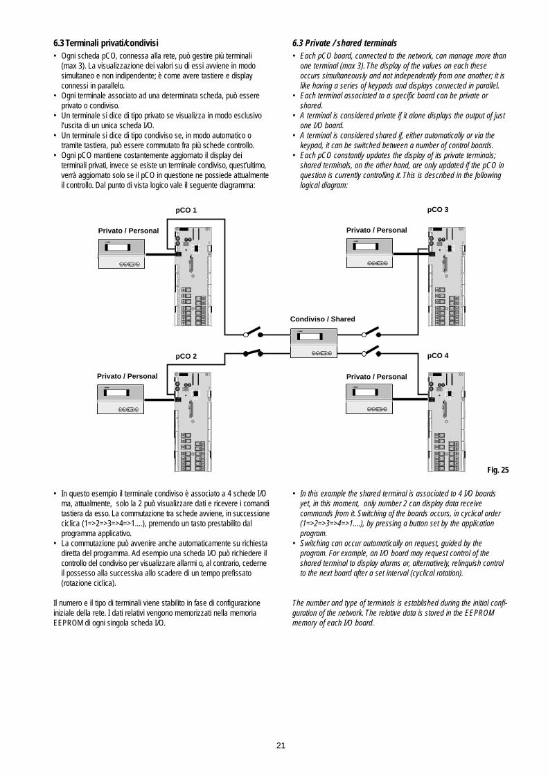
6.3 Terminali privati/condivisi• Ogni scheda pCO, connessa alla rete, può gestire più terminali
(max 3). La visualizzazione dei valori su di essi avviene in modo simultaneo e non indipendente; è come avere tastiere e display connessi in parallelo.
• Ogni terminale associato ad una determinata scheda, può essere privato o condiviso.
• Un terminale si dice di tipo privato se visualizza in modo esclusivo l’uscita di un unica scheda I/O.
• Un terminale si dice di tipo condiviso se, in modo automatico o tramite tastiera, può essere commutato fra più schede controllo.
• Ogni pCO mantiene costantemente aggiornato il display dei terminali privati, invece se esiste un terminale condiviso, quest’ultimo,verrà aggiornato solo se il pCO in questione ne possiede attualmenteil controllo. Dal punto di vista logico vale il seguente diagramma:
• In questo esempio il terminale condiviso è associato a 4 schede I/O ma, attualmente, solo la 2 può visualizzare dati e ricevere i comanditastiera da esso. La commutazione tra schede avviene, in successioneciclica (1=>2=>3=>4=>1....), premendo un tasto prestabilito dal programma applicativo.
• La commutazione può avvenire anche automaticamente su richiesta diretta del programma. Ad esempio una scheda I/O può richiedere il controllo del condiviso per visualizzare allarmi o, al contrario, cederneil possesso alla successiva allo scadere di un tempo prefissato(rotazione ciclica).
Il numero e il tipo di terminali viene stabilito in fase di configurazioneiniziale della rete. I dati relativi vengono memorizzati nella memoriaEEPROM di ogni singola scheda I/O.
6.3 Private / shared terminals• Each pCO board, connected to the network, can manage more than
one terminal (max 3). The display of the values on each these occurs simultaneously and not independently from one another; it is like having a series of keypads and displays connected in parallel.
• Each terminal associated to a specific board can be private or shared.
• A terminal is considered private if it alone displays the output of just one I/O board.
• A terminal is considered shared if, either automatically or via the keypad, it can be switched between a number of control boards.
• Each pCO constantly updates the display of its private terminals;shared terminals, on the other hand, are only updated if the pCO in question is currently controlling it. This is described in the following logical diagram:
• In this example the shared terminal is associated to 4 I/O boards yet, in this moment, only number 2 can display data receive commands from it. Switching of the boards occurs, in cyclical order (1=>2=>3=>4=>1....), by pressing a button set by the application program.
• Switching can occur automatically on request, guided by the program. For example, an I/O board may request control of the shared terminal to display alarms or, alternatively, relinquish control to the next board after a set interval (cyclical rotation).
The number and type of terminals is established during the initial confi-guration of the network. The relative data is stored in the EEPROMmemory of each I/O board.
21
on/off enteralarm
on/off enteralarmon/off enteralarm
on/off enteralarm
pCO 1
pCO 2
pCO 3
pCO 4
Privato / Personal Privato / Personal
Privato / Personal
Condiviso / Shared
on/off enteralarm
Privato / Personal
Fig. 25

6.4 Connessioni elettriche pLANLa connessione tra schede in pLAN si effettua usando un cavo scher-mato AWG20/22 costituito da una coppia twistata e lo schermo. Leschede vanno collegate in parallelo facendo riferimento al morsetto J11.ATTENZIONE rispettare le polarità di rete: l’RX/TX+ di una schedadeve essere collegato al RX/TX+ delle altre schede ; la stessa cosaper RX/TX-.Di seguito viene rappresentato lo schema di più schede collegate inrete pLAN alimentate dallo stesso trasformatore: (tipica applicazione dipiù schede collegate all’interno di uno stesso quadro elettrico).
Di seguito viene rappresentato lo schema di più schede collegate inrete pLAN alimentate da trasformatori diversi (con il G0 non connessoa terra): (tipica applicazione di più schede che fanno parte di quadrielettrici diversi).Attenzione: Con questa configurazione è necessario installare trasfor-matori di sicurezza (doppio isolamento)
Di seguito viene rappresentato lo schema di più schede collegate inrete pLAN alimentate da trasformatori diversi con unico riferimento diterra: (tipica applicazione di più schede che fanno parte di quadri elettrici diversi)Attenzione: Il collegamento a terra deve essere effettuato sulla stessalinea di terra (stesso pozzetto di terra per tutte le schede pCO).
6.4 pLAN electrical connectionsConnection between boards in a pLAN network is carried out using anAWG20/22 shielded cable, made up of a twisted pair plus shield. Theboards are connected in parallel, with terminal J11 as the reference.Pay ATTENTION to the network polarity: RX/TX+ on one board mustbe connected to RX/TX+ on the other boards; the same is true forRX/TX-.The following is a diagram of a number of boards connected in a pLANnetwork and powered by the same transformer: (typical application: anumber of boards connected inside the same electrical panel).
The following is a diagram of a number of boards connected in a pLANnetwork and powered by different transformers (with G0 not earthed):(typical application: a number of boards inside different electricalpanels.Attention: With this configuration a safety transformer (double insulated)must be installed
The following is a diagram of a number of boards connected in a pLANnetwork and powered by different transformers with the same earthreference: (typical application: a number of boards inside different electrical panels)Attention: The earth connection must be made to the same earth line(same earth plate for all the pCO boards).
22
J11
J17
J11
J17
J11
J17
GNDRX/TX-RX/TX+
GG0
GNDRX/TX-RX/TX+
GG0
GNDRX/TX-RX/TX+
GG0
AWG20/22 AWG20/22 AWG20/22
J11
J17
J11
J17
J11
J17
GNDRX/TX-RX/TX+
GG0
GNDRX/TX-RX/TX+
GG0
GNDRX/TX-RX/TX+
GG0
AWG20/22 AWG20/22 AWG20/22
J11
J17
J11
J17
J11
J17
GNDRX/TX-RX/TX+
GG0
GNDRX/TX-RX/TX+
GG0
GNDRX/TX-RX/TX+
GG0
AWG20/22 AWG20/22 AWG20/22
Fig. 26
Fig. 27
Fig. 28

6.5 Remotazione terminale con rete pLANQuando le schede pCO sono connesse in rete pLAN il terminale puòessere remotato fino a 50 metri se si usa cavo di tipo telefonico, men-tre se si usa un cavo schermato può essere remotato fino a 200 metri.Di seguito sono rappresentati gli schemi di collegamento delle varieconfigurazioni:
Per tale remotazione si prescrive l'inserimento di una ferrite - cod.0907858AXX come illustrato in Fig. 29.c. Le Figg. 29.a e 29.b raffigurano rispettivamente la ferrite da installare in posizione aperta echiusa. La ferrite va montata sul cavo telefonico di collegamento (rif.to F su Fig. 21), lato terminale, curando di far compiere al cavo ungiro ad anello sulla ferrite stessa.
Remotazione terminale con rete pLAN con cavo telefonico.
Remotazione terminale con rete pLAN con cavo schermato Awg24 con2 coppie twistate + lo schermo.
6.6 Caratteristiche tecniche rete pLANStandard comunicazione: RS485.Baud-rate: 65,2 Kbit/s.Protocollo: Multimaster (il protocollo è proprietario Carel).Lunghezza massima della rete: 500 metri.
6.7 Componenti rete pLANSchede base 8 ingressi analogici PCOB000*21Terminali pCO standard LCD 4x20, 6 LED, 3 LED o graficiSchede indirizzamento PCOADR0000, PCOCLKMEM0Scheda di derivazione TCON6J0000 per remotazione terminali perdistanze superiore a 50 metri.
6.5 Remote installation of the terminal in a pLAN networkWhen pCO boards are connected in a pLAN network the terminal can beremotely-located at a distance of up to 50 metres, if using a telephone-typecable; if using a shielded cable, it can be located at a distance of up to200 metres. The following figures show the connection diagrams for thevarious configurations:
For such remotation you must insert a ferrite - code 0907858AXX asshown in Fig. 29.c. Fig. No.29.a and No.29.b show how to install the ferrite in open and closed position respectively. The ferrite must be placed on the connecting telephone cable (ref. F, on Fig. 21), terminalside, making the cable ring-turn on the ferrite itself.
Remote terminal with pLAN network and telephone-type cable
Remote terminal with pLAN network and Awg24 shielded cable with 2twisted pairs + shield
6.6 Technical characteristics of the pLAN networkCommunication standard: RS485.Baud-rate: 65.2 Kbit/s.Protocol: Multimaster (Carel proprietary protocol).Maximum length of the network: 500 metres.
6.7 Components in the pLAN networkMain boards with 8 analogue inputs, PCOB000*21pCO standard terminals, 4x20 LCD, 6 LED, 3 LED or graphicAddressing boards, PCOADR0000, PCOCLKMEM0TCON6J0000 derivation card for remote terminal location of distancesabove 50 metres.
23
J11J17
on/off alarm enter
pCO Terminal
menu I/O set prog.
?info
GraphicRoom 1
Temp
on/off enteralarm
F
50 m
J11 J17
Fig. 29
Fig. 30
Fig. 29c
Fig. 29bFig. 29a
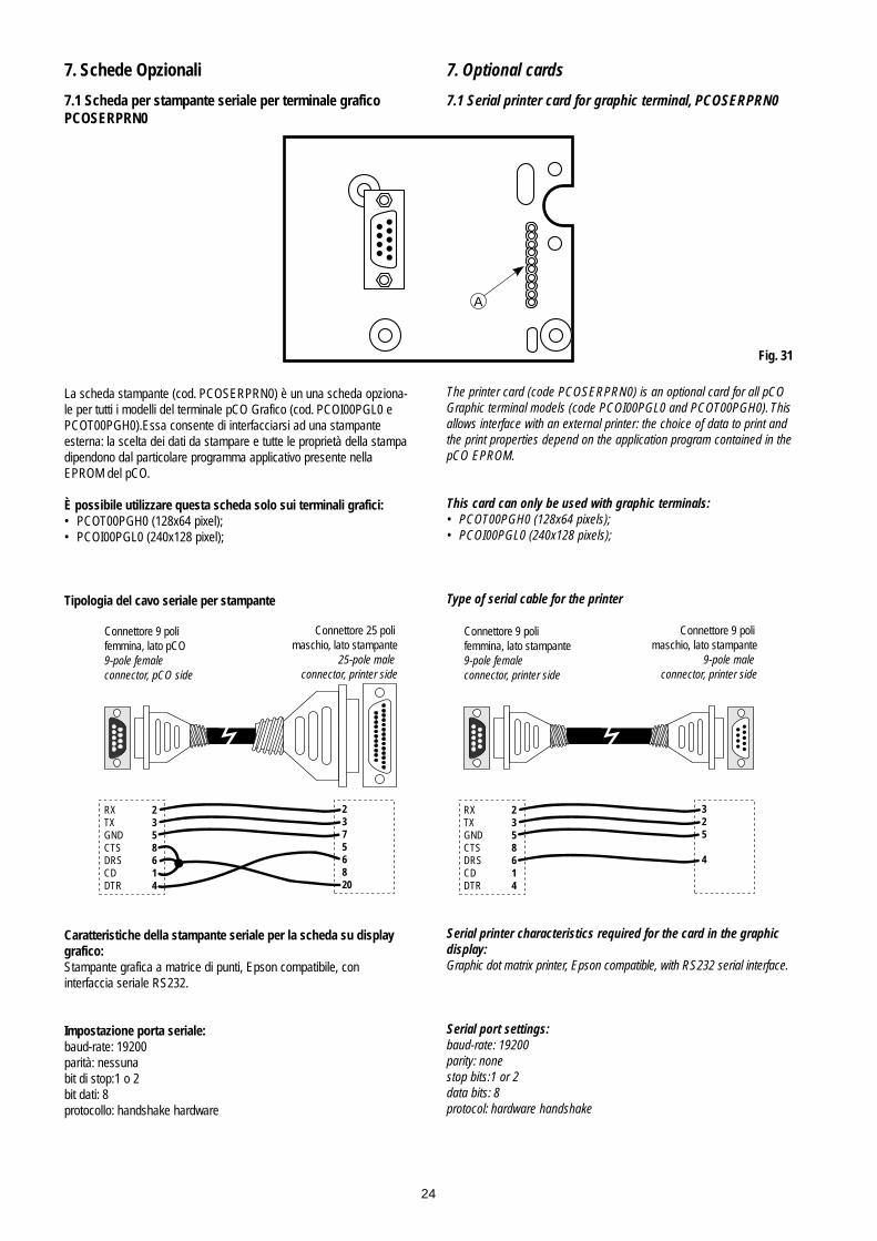
7. Schede Opzionali
7.1 Scheda per stampante seriale per terminale graficoPCOSERPRN0
La scheda stampante (cod. PCOSERPRN0) è un una scheda opziona-le per tutti i modelli del terminale pCO Grafico (cod. PCOI00PGL0 ePCOT00PGH0).Essa consente di interfacciarsi ad una stampanteesterna: la scelta dei dati da stampare e tutte le proprietà della stampadipendono dal particolare programma applicativo presente nellaEPROM del pCO.
È possibile utilizzare questa scheda solo sui terminali grafici:• PCOT00PGH0 (128x64 pixel);• PCOI00PGL0 (240x128 pixel);
Tipologia del cavo seriale per stampante
Caratteristiche della stampante seriale per la scheda su displaygrafico:Stampante grafica a matrice di punti, Epson compatibile, con interfaccia seriale RS232.
Impostazione porta seriale:baud-rate: 19200parità: nessunabit di stop:1 o 2bit dati: 8protocollo: handshake hardware
7. Optional cards
7.1 Serial printer card for graphic terminal, PCOSERPRN0
The printer card (code PCOSERPRN0) is an optional card for all pCOGraphic terminal models (code PCOI00PGL0 and PCOT00PGH0). Thisallows interface with an external printer: the choice of data to print andthe print properties depend on the application program contained in thepCO EPROM.
This card can only be used with graphic terminals:• PCOT00PGH0 (128x64 pixels);• PCOI00PGL0 (240x128 pixels);
Type of serial cable for the printer
Serial printer characteristics required for the card in the graphicdisplay:Graphic dot matrix printer, Epson compatible, with RS232 serial interface.
Serial port settings:baud-rate: 19200parity: nonestop bits:1 or 2data bits: 8protocol: hardware handshake
24
A
Fig. 31
Connettore 9 poli femmina, lato pCO9-pole female connector, pCO side
Connettore 25 poli maschio, lato stampante
25-pole male connector, printer side
RX 2TX 3GND 5CTS 8DRS 6CD 1DTR 4
2 3 7 5 6 8 20
Connettore 9 poli femmina, lato stampante9-pole female connector, printer side
Connettore 9 poli maschio, lato stampante
9-pole male connector, printer side
RX 2TX 3GND 5CTS 8DRS 6CD 1DTR 4
3 2 5 4
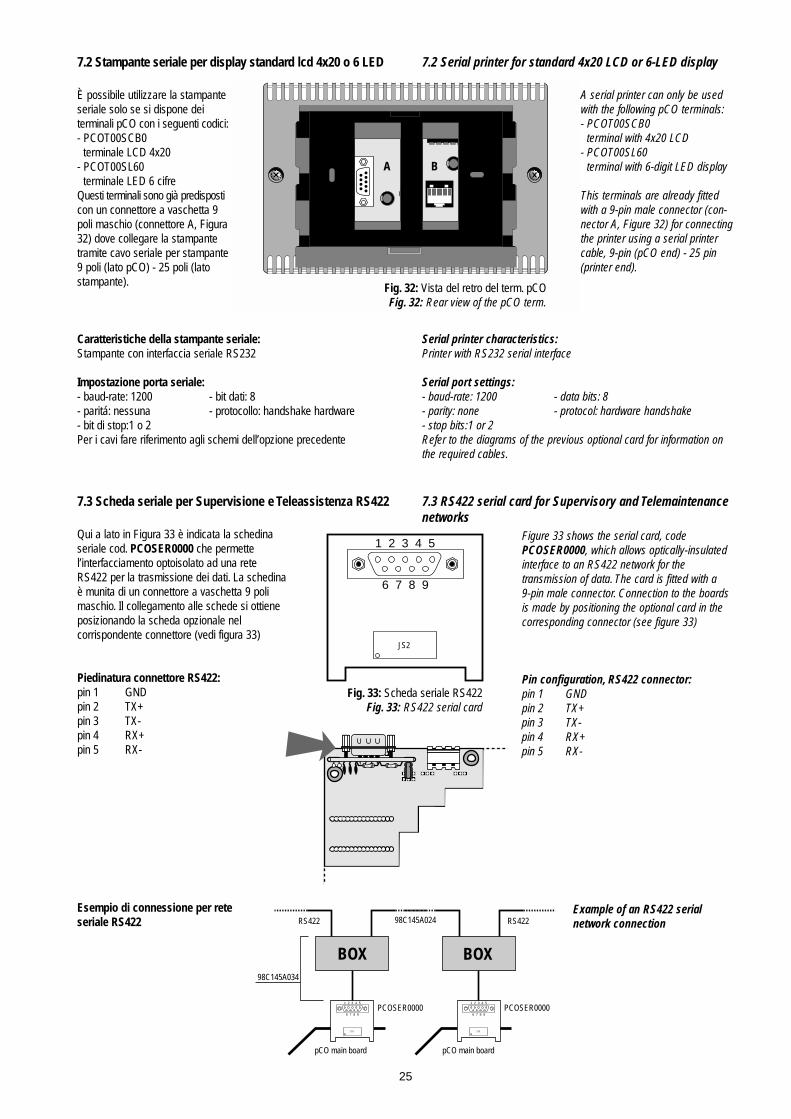
7.2 Stampante seriale per display standard lcd 4x20 o 6 LED
È possibile utilizzare la stampanteseriale solo se si dispone dei terminali pCO con i seguenti codici:- PCOT00SCB0
terminale LCD 4x20- PCOT00SL60
terminale LED 6 cifreQuesti terminali sono già predisposticon un connettore a vaschetta 9poli maschio (connettore A, Figura32) dove collegare la stampante tramite cavo seriale per stampante9 poli (lato pCO) - 25 poli (latostampante).
Caratteristiche della stampante seriale:Stampante con interfaccia seriale RS232
Impostazione porta seriale:- baud-rate: 1200 - bit dati: 8- paritá: nessuna - protocollo: handshake hardware- bit di stop:1 o 2Per i cavi fare riferimento agli schemi dell’opzione precedente
7.3 Scheda seriale per Supervisione e Teleassistenza RS422
Qui a lato in Figura 33 è indicata la schedinaseriale cod. PCOSER0000 che permette l’interfacciamento optoisolato ad una reteRS422 per la trasmissione dei dati. La schedinaè munita di un connettore a vaschetta 9 polimaschio. Il collegamento alle schede si ottieneposizionando la scheda opzionale nel corrispondente connettore (vedi figura 33)
Piedinatura connettore RS422:pin 1 GNDpin 2 TX+pin 3 TX-pin 4 RX+pin 5 RX-
Esempio di connessione per reteseriale RS422
7.2 Serial printer for standard 4x20 LCD or 6-LED display
A serial printer can only be usedwith the following pCO terminals:- PCOT00SCB0
terminal with 4x20 LCD- PCOT00SL60
terminal with 6-digit LED display
This terminals are already fittedwith a 9-pin male connector (con-nector A, Figure 32) for connectingthe printer using a serial printercable, 9-pin (pCO end) - 25 pin(printer end).
Serial printer characteristics:Printer with RS232 serial interface
Serial port settings:- baud-rate: 1200 - data bits: 8- parity: none - protocol: hardware handshake- stop bits:1 or 2Refer to the diagrams of the previous optional card for information onthe required cables.
7.3 RS422 serial card for Supervisory and Telemaintenancenetworks
Figure 33 shows the serial card, code PCOSER0000, which allows optically-insulatedinterface to an RS422 network for the transmission of data. The card is fitted with a 9-pin male connector. Connection to the boardsis made by positioning the optional card in thecorresponding connector (see figure 33)
Pin configuration, RS422 connector:pin 1 GNDpin 2 TX+pin 3 TX-pin 4 RX+pin 5 RX-
Example of an RS422 serialnetwork connection
25
A B
Fig. 32: Vista del retro del term. pCOFig. 32: Rear view of the pCO term.
JS2
1 2 3 4 5
6 7 8 9
Fig. 33: Scheda seriale RS422Fig. 33: RS422 serial card
JS2
1 2 3 4 5
6 7 8 9
JS2
1 2 3 4 5
6 7 8 9
BOX BOX
RS422 RS42298C145A024
pCO main board pCO main board
PCOSER0000 PCOSER0000
98C145A034
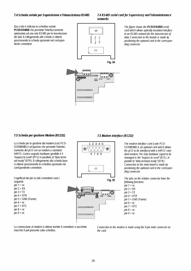
7.4 Scheda seriale per Supervisione e Teleassistenza RS485
Qui a lato è indicata la schedina seriale PCOSER4850 che permette l’interfacciamentooptoisolato ad una rete RS485 per la trasmissionedei dati. Il collegamento alle schede si ottieneposizionando la scheda opzionale nel corrispon-dente connettore
7.5 Scheda per gestione Modem (RS232)
La scheda per la gestione del modem (cod. PCO-SERMDM0) è un’opzione che permette l’interfac-ciamento del pCO con un modem a standardHAYES. L’unico segnale hardware gestibile è il“request to send” (RTS) in parallelo al “data termi-nal ready” (DTR). Il collegamento alla scheda basesi ottiene posizionando la schedina opzionale nelcorrispondente connettore.
I significati dei pin su tale connettore sono iseguenti:pin 1 = ncpin 2 = RXpin 3 = TXpin 4 = DTRpin 5 = GND (Frame)pin 6 = ncpin 7 = RTSpin 8 = ncpin 9 = nc
La connessione al modem si ottiene tramite il connettore a vaschettamaschio 9 poli presente sulla schedina.
7.4 RS485 serial card for Supervisory and Telemaintenancenetworks
The figure shows the PCOSER4850 serialcard which allows optically-insulated interfaceto an RS485 network for the transmission ofdata. Connection to the boards is made bypositioning the optional card in the correspon-ding connector.
7.5 Modem interface (RS232)
The modem interface card (code PCO-SERMDM0) is an optional card which allowsthe pCO to be interfaced with a HAYES stan-dard modem. The only hardware signal to bemanaged is the “request to send” (RTS), inparallel to “data terminal ready” (DTR).Connection to the main board is made bypositioning the optional card in the correspon-ding connector.
The pins on the relative connector have thefollowing functions:pin 1 = ncpin 2 = RXpin 3 = TXpin 4 = DTRpin 5 = GND (Frame)pin 6 = ncpin 7 = RTSpin 8 = ncpin 9 = nc
Connection to the modem is made using the 9-pin male connector onthe card.
26
M1
JS2
GR
OU
ND
RX
+ /
TX
+
RX
- / T
X-
Fig. 34
JS2
1 2 3 4 5
6 7 8 9
Fig. 35

7.6 Scheda orologio
In Figura 36 è indicata la scheda orologio a temporeale (cod. CLK0000000) che permette di visualiz-zare data e ora correnti. Nel caso si vogliano utiliz-zare le fasce orarie (nei programmi che le gesti-scono) questa schedina è indispensabile. Il colle-gamento alle schede si ottiene posizionando lascheda opzionale nel corrispondente connettore.Quando al pCO viene a mancare alimentazione, labatteria al litio mantiene attiva la scheda orologioper oltre un mese.
7.7 Scheda indirizzamento per rete pLAN
In figura 37 è indicata la scheda indirizzamento(cod.PCOADR0000) che permette alle schedebase pCO 8 ingressi di essere collegate in retelocale pLAN (nei programmi che la gestiscono).Il collegamento alle schede si ottiene posizionandola scheda opzionale nel corrispondente connettore. Per le istruzioni su come effettuare ilcorretto indirizzamento vedere capitolo pLAN.
7.6 Clock card
Figure 36 shows the real-time clock card(code CLK0000000), which allows thedisplay of the current date and time. Thiscard is essential if the control program inclu-des time band management. Connection tothe main boards is made by positioning theoptional card in the corresponding connector.If the pCO is disconnected from its powersource, the lithium battery will keep the cardactive for over one month.
7.7 Addressing card for pLAN networks
Figure 37 shows the addressing card (codePCOADR0000) which allows 8-input pCOmain boards to be connected in pLAN localnetworks (as managed by their programs). Connection to the boards is madeby positioning the optional card in the corresponding connector.For instructions on how to correctly addressthe board, see the chapter on the pLAN.
27
Figura 36: Scheda orologioFigure 36: Clock card
Figura 37: Scheda IndirizzamentoFigure 37: Addressing card

7.8 Scheda indirizzamento, orologio, 32 Kbyte EEPROM
In figura 38 è indicata la scheda indirizzamento(cod.PCOCLKMEM0) che permette alle schedebase pCO 8 ingressi di essere collegate in retelocale pLAN (nei programmi che la gestiscono).Il collegamento alle schede si ottiene posizionan-do la scheda opzionale nel corrispondente connettore. Sono presenti anche un real timeclock e una EEPROM da 32 Kbyte (memoria permanente). Per le istruzioni su come effettuareil corretto indirizzamento vedere capitolo pLAN.
7.9 Scheda per gestione umidificatore OEMQuesta interfaccia (cod.PCOU-MID000) permette di controllare iparametri fondamentali degli umidifi-catori OEM prodotti da CAREL (livelloe conducibilità acqua nel cilindro,sensore TAM di assorbimento corren-te) direttamente dal regolatore elettro-nico a microprocessore pCO. I valoriraccolti dagli appositi sensori vengo-no convertiti in segnali comprensibilidagli ingressi presenti nella schedaelettronica pCO (per maggiori infor-mazioni si rimanda al relativo manua-le utente del programma applicativo).Nota: Gli ingressi analogici B7 e B8,nel pCO, dovranno essere selezionatisu 0÷1 Volt.
7.10 Installazione schede opzionaliPer il corretto montaggio delle schedeopzionali è necessario seguire alcune fasiessenziali:• Cercare la posizione esatta in cui deve
essere inserita la scheda opzionale.• Individuato il connettore la scheda deve
essere infilata nelle apposite guide (i due fori) che si trovano ai lati dei contatti.
• Durante il montaggio assicurarsi che la scheda opzionale sia perfettamente verticale rispetto al pCO per evitare di danneggiare i contatti.
• Il connettore a pettine deve essere inserito perfettamente nel connettore presente sulla scheda opzionale.
Togliere l’alimentazione alla scheda pCO prima di inserire/rimuo-vere le schede opzionali.Per ulteriori dettagli fare riferimento al foglio istruzioni in dotazione alleschede stesse.
7.8 Addressing, clock, 32Kbyte EEPROM card
Figure 38 shows the addressing card(codePCOADR0000) which allows 8-input pCOmain boards to be connected in pLAN localnetworks (as managed by their programs).Connection to the boards is made by positio-ning the optional card in the correspondingconnector. A real-time clock and 32 KbyteEEPROM (permanent memory) are also present. For instructions on how to correctlyaddress the board, see the chapter on thepLAN.
7.9 OEM humidifier management card This interface (codePCOUMID000)allows the control of the fundamen-tal parameters of the OEM humidi-fiers manufactured by CAREL (leveland conductivity of the water in thecylinder, TAM sensor for currentabsorption) directly from the pCOmicroprocessor-based electroniccontrol. The values measured by thesensors are converted into signalswhich can be read by the inputs onthe pCO electronic board (for moreinformation refer to the user manualfor the application program).Note: Analogue inputs B7 and B8must be selected as 0÷1V in the pCO board.
7.10 Installing the optional cardsTo correctly mount the optional cards, anumber of fundamental steps must be followed:• Locate the exact position where the
optional card is to be inserted.• Once having found the connector the
card must be slotted into the guides (two holes) located to the sides of the contacts.
• When mounting check that optional cardis perfectly vertical in respect to the pCO to avoid damaging the contacts.
• The pins of the connector on the board must be properly inserted into the connector on the optional card.
Disconnect power from the pCO board before inserting/removingthe optional cards.For more details see the instruction sheets supplied with the cards inquestion.
28
Figura 38: Scheda Indirizzamento/orologioFigure 38: Addressing/clock card
J3
J2
J1
J6
J5
J4
B8G0B7
GG0
O1O2
T1T2
C1C2
L1L2
5 5 74.5 5 5
56.5
Fig. 39
Fig. 40

8. Ricerca ed eliminazione guastiL’unità non si avvia (LED sulla scheda base di presenza rete spen-to, LCD spento, altri LED spenti)
Verificare:1. presenza tensione di rete;2. che a valle del trasformatore di tensione di alimentazione vi siano
24 Vac/Vdc;3. il corretto inserimento del connettore di alimentazione a
24 Vac/Vdc nell’apposito supporto;4. che il fusibile di protezione sia integro;5. che il cavo telefonico di connessione tra terminale (se presente)
e scheda base sia collegato correttamente.
All’accensione si presenta una situazione del tipo• LED di allarme acceso;• LCD senza alcuna scritta o con scritte casuali;• cicalino attivo.
Verificare:1. corretto inserimento EPROM;2. che non siano stati piegati i piedini nell’inserimento della EPROM;3. che non sia stato manomesso il chip microprocessore:
in tal caso chiamare l’assistenza.
Letture errate dei segnali in ingresso
Verificare:1. l’eventuale taratura degli ingressi (da programma);2. la corretta alimentazione della scheda base e delle sonde;3. la separazione dell’alimentazione degli ingressi digitali
dall’alimentazione del pCO. Può essere utilizzato un trasformatore 24 Vac/24 Vac da 12 VA.
4. che la connessione dei fili delle sonde sia secondo istruzioni 5. che i cavi delle sonde siano posizionati a sufficiente distanza da
possibili fonti di disturbo elettromagnetico (cavi di potenza, contattori, cavi con alte tensioni e con dispositivi collegati ad alto assorbimento allo spunto);
6. che tra sensore ed eventuale pozzetto sonda non vi sia un’alta resistenza termica. Eventualmente inserire nei pozzetti pasta o olioconduttivo per garantire una buona trasmissione della temperatura;
7. se si è in presenza di errore di sonda oppure se si tratta di un errore di conversione del pCO, le verifiche si diversificano a seconda del tipo di sonda:
Sonde attive di temperatura/umidità con segnale -0,5 V÷1 V:misurando con un voltmetro tra i morsetti Bn ed AVSS si ha il segnale di sonda e si puó verificare la corrispondenza tra tensionee grandezza: 1 mVdc corrisponde a 0,1°CEsempio: leggendo 200 mVdc (0,2 Vdc) la sonda invia un segnaleche corrisponde a 20°C/20%U.R.; applicando la stessa logica a 0 mVdc corrispondono a 0ºC/0% U.R.;
Sonde di pressione: nel caso emergano errori nella lettura di queste sonde verificare che:• gli ingressi analogici di tali sonde siano predisposti per accettare
segnali 4÷20 mA;• i fondoscala impostati via software corrispondano alle sonde
impiegate.Misurando con un voltmetro la tensione presente ai capi dei morsetti Bn ed AVSS si ottiene indirettamente la corrente del segnale di sonda, in quanto l’ingresso ha una impedenza di 50 Ω, applicando la formula I=V/R.Il valore di pressione “Ps” che la sonda sta inviando è così ricavabile (FS=Fondo Scala):
Ps = (Vmis/50 - 0,004) x (FSmax - FSmin) / 0,016 + Fsmin
Esempio: la sonda impiegata ha FSmin=-0,5 bar, FSmax=7 bar;la tensione letta è pari a Vmis= 0,5 Vdc.La pressione Ps che la sonda sta misurando vale:
Ps = (0,5/50 - 0,004) x [7 - (-0,5)] / 0,016 + (-0,5)=2,3 bar
8.TroubleshootingThe unit does not switch on (the LED on the main board signallingnetwork presence is off, the LCD is off, other LEDs are off)
Check:1. the presence of main power;2. that the output voltage of the power transformer is 24Vac/Vdc;3. that the 24Vac/Vdc power connector is correctly inserted;4. that the overload fuse is in tact;5. that the telephone-type cable connecting the terminal (if present)
and the main board is correctly connected.
On switching on one of these situations occurs• the alarm LED is on;• the LCD is blank or displays random characters;• the buzzer is on.
Check:1. that the is EPROM correctly inserted2. that the pins of the EPROM were not bent when it was inserted;3. that the microprocessor chip has not been tampered with:
if so, call the service department.
Erroneous reading of the input signals
Check:1. the calibration of the inputs (from the program);2. the correct power to the main board and the probes;3. that the power to the digital inputs and power to the pCO are
separated. A 24Vac/24Vac, 12VA transformer can be used.4. that the connection to the wires from the probes is as per the
instructions;5. that the probe cables are located far enough away from possible
sources of electromagnetic disturbance (power cables, contactors, high-voltage cables or cables connected to devices with high peak absorption);
6. that there is not a high degree of heat resistance between the sensor and the probe cap (if present). If necessary introduce conductive paste or oil into the caps to ensure good temperature transfer;
7. if there is a probe error or pCO conversion error, the checks to be carried out vary according to the type of probe:
Active temperature/humidity probes with -0.5V÷1V signal:measure, using a voltmeter between terminals Bn and AVSS, the probe signal and check that the voltage corresponds to the temperature/humidity value: 1mVdc corresponds to 0.1°CExample: reading 200mVdc (0.2Vdc), the probe sends a signal which corresponds to 20°C/20%r.H.; using the same logic, 0mVdc corresponds to 0ºC/0% r.H.;
Pressure probes: if there are errors in reading these probes, check that:• the analogue inputs from these probes are set to receive signals
of 4÷20mA;• the full scale set by the software corresponds to that of the
probes used.By measuring the voltage between Bn and AVSS, the current of the probe signal can be easily calculated, considering that the input has an impedance of 50Ω, applying the formula I=V/R.The pressure value “Ps” sent by the probe can be calculated as follows (FS=Full Scale):
Ps = (Vread/50 - 0.004) x (FSmax - FSmin) / 0.016 + Fsmin
Example: the probe used has a FSmin=-0.5bar, FSmax=7bar;the voltage read is Vread= 0.5Vdc.The pressure Ps that the probe is measuring is thus:
Ps = (0.5/50 - 0.004) x [7 - (-0.5)] / 0.016 + (-0.5)=2.3bar
29
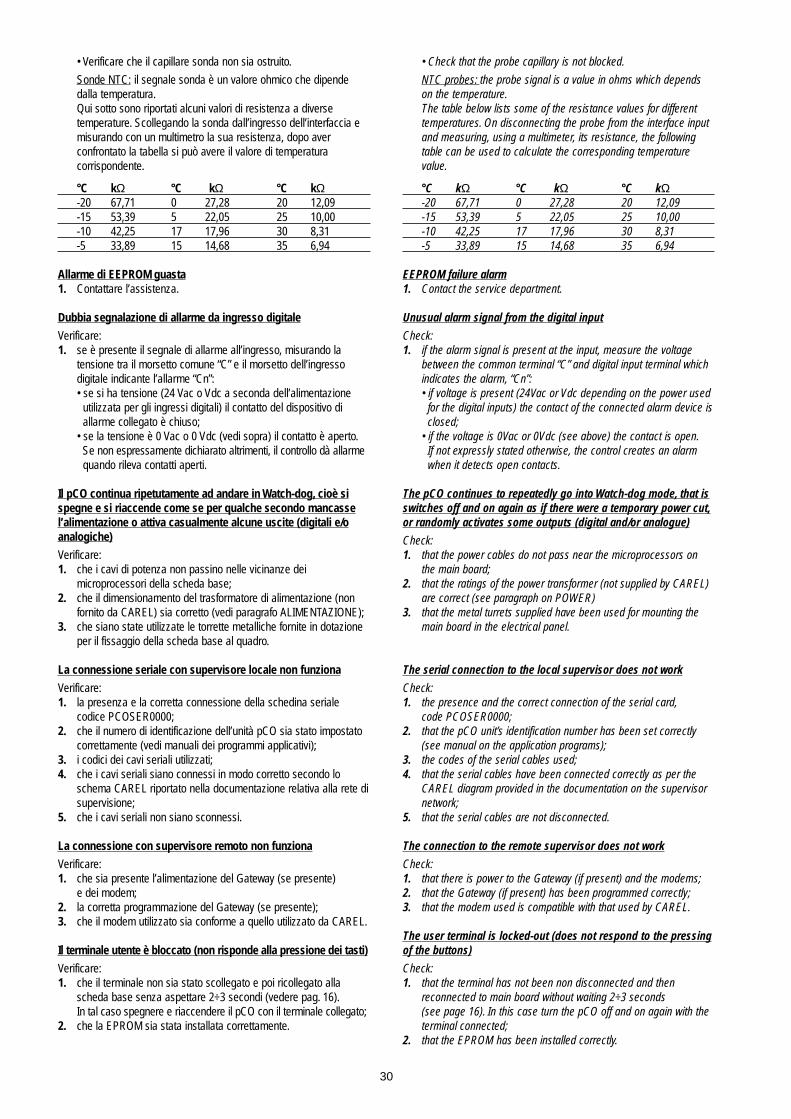
• Verificare che il capillare sonda non sia ostruito.
Sonde NTC: il segnale sonda è un valore ohmico che dipende dalla temperatura.Qui sotto sono riportati alcuni valori di resistenza a diverse temperature. Scollegando la sonda dall’ingresso dell’interfaccia e misurando con un multimetro la sua resistenza, dopo aver confrontato la tabella si può avere il valore di temperatura corrispondente.
°C kΩ °C kΩ °C kΩ-20 67,71 0 27,28 20 12,09-15 53,39 5 22,05 25 10,00-10 42,25 17 17,96 30 8,31-5 33,89 15 14,68 35 6,94
Allarme di EEPROM guasta1. Contattare l’assistenza.
Dubbia segnalazione di allarme da ingresso digitale
Verificare:1. se è presente il segnale di allarme all’ingresso, misurando la
tensione tra il morsetto comune “C” e il morsetto dell’ingresso digitale indicante l’allarme “Cn”:• se si ha tensione (24 Vac o Vdc a seconda dell’alimentazione
utilizzata per gli ingressi digitali) il contatto del dispositivo di allarme collegato è chiuso;
• se la tensione è 0 Vac o 0 Vdc (vedi sopra) il contatto è aperto.Se non espressamente dichiarato altrimenti, il controllo dà allarme quando rileva contatti aperti.
Il pCO continua ripetutamente ad andare in Watch-dog, cioè sispegne e si riaccende come se per qualche secondo mancassel’alimentazione o attiva casualmente alcune uscite (digitali e/oanalogiche)
Verificare:1. che i cavi di potenza non passino nelle vicinanze dei
microprocessori della scheda base;2. che il dimensionamento del trasformatore di alimentazione (non
fornito da CAREL) sia corretto (vedi paragrafo ALIMENTAZIONE);3. che siano state utilizzate le torrette metalliche fornite in dotazione
per il fissaggio della scheda base al quadro.
La connessione seriale con supervisore locale non funziona
Verificare:1. la presenza e la corretta connessione della schedina seriale
codice PCOSER0000;2. che il numero di identificazione dell’unità pCO sia stato impostato
correttamente (vedi manuali dei programmi applicativi);3. i codici dei cavi seriali utilizzati;4. che i cavi seriali siano connessi in modo corretto secondo lo
schema CAREL riportato nella documentazione relativa alla rete disupervisione;
5. che i cavi seriali non siano sconnessi.
La connessione con supervisore remoto non funziona
Verificare:1. che sia presente l’alimentazione del Gateway (se presente)
e dei modem;2. la corretta programmazione del Gateway (se presente);3. che il modem utilizzato sia conforme a quello utilizzato da CAREL.
Il terminale utente è bloccato (non risponde alla pressione dei tasti)
Verificare:1. che il terminale non sia stato scollegato e poi ricollegato alla
scheda base senza aspettare 2÷3 secondi (vedere pag. 16).In tal caso spegnere e riaccendere il pCO con il terminale collegato;
2. che la EPROM sia stata installata correttamente.
• Check that the probe capillary is not blocked.
NTC probes: the probe signal is a value in ohms which depends on the temperature.The table below lists some of the resistance values for different temperatures. On disconnecting the probe from the interface input and measuring, using a multimeter, its resistance, the following table can be used to calculate the corresponding temperature value.
°C kΩ °C kΩ °C kΩ-20 67,71 0 27,28 20 12,09-15 53,39 5 22,05 25 10,00-10 42,25 17 17,96 30 8,31-5 33,89 15 14,68 35 6,94
EEPROM failure alarm1. Contact the service department.
Unusual alarm signal from the digital input
Check:1. if the alarm signal is present at the input, measure the voltage
between the common terminal “C” and digital input terminal which indicates the alarm, “Cn”:• if voltage is present (24Vac or Vdc depending on the power used
for the digital inputs) the contact of the connected alarm device isclosed;
• if the voltage is 0Vac or 0Vdc (see above) the contact is open.If not expressly stated otherwise, the control creates an alarm when it detects open contacts.
The pCO continues to repeatedly go into Watch-dog mode, that isswitches off and on again as if there were a temporary power cut,or randomly activates some outputs (digital and/or analogue)
Check:1. that the power cables do not pass near the microprocessors on
the main board;2. that the ratings of the power transformer (not supplied by CAREL)
are correct (see paragraph on POWER)3. that the metal turrets supplied have been used for mounting the
main board in the electrical panel.
The serial connection to the local supervisor does not work
Check:1. the presence and the correct connection of the serial card,
code PCOSER0000;2. that the pCO unit’s identification number has been set correctly
(see manual on the application programs);3. the codes of the serial cables used;4. that the serial cables have been connected correctly as per the
CAREL diagram provided in the documentation on the supervisor network;
5. that the serial cables are not disconnected.
The connection to the remote supervisor does not work
Check:1. that there is power to the Gateway (if present) and the modems;2. that the Gateway (if present) has been programmed correctly;3. that the modem used is compatible with that used by CAREL.
The user terminal is locked-out (does not respond to the pressingof the buttons)
Check:1. that the terminal has not been non disconnected and then
reconnected to main board without waiting 2÷3 seconds (see page 16). In this case turn the pCO off and on again with the terminal connected;
2. that the EPROM has been installed correctly.
30

9. Caratteristiche tecniche
9.1 Caratteristiche tecniche della scheda base PCOB
Avvertenza: per l’alimentazione di eventuali sonde attive è possibileutilizzare i 24 Vdc disponibili al morsetto J1 (+24 Vdc); la corrente massima erogabile è di 80 mA.
9.Technical specifications
9.1 Technical specifications of the pCO main board PCOB
Warning: it is possible to power active probes using the 24Vdc availa-ble at terminal J1 (+24Vdc); the maximum current supplied is 80mA.
31
Caratteristiche meccaniche / Mechanical specifications
Dimensioni / Dimensions Scheda inseribile su 17 moduli DIN; 107x297,5 mm / Board to be mounted on 17 DIN modules; 107x297.5mm
Fissaggio / Mounting 4 fasteners 4 mm e 6 torrette metalliche, compresi nella confezione4x4mm fasteners and 6 metal turrets, included in the packaging
Protezione e fissaggi opzionali Fissaggio su guida DIN tramite apposito adattatore metallico.Protezione meccanica e schermatura antidisturbo tramite box metallico (adattatore a guida DIN più coperchio superiore)
Optional safety devices and mountings Mounting on DIN rail using special metal adapter.Mechanical protection and anti-disturbance screening using a metal box (DIN rail adapter plus upper cover)
Connessioni / Connections A seconda delle necessità del cliente morsettiera con connettori maschio/femmina estraibili o a vite fissi.Tensione massima: 250 Vac According to customer requirements, terminal block with removable male/female connectors or fixed screws.Maximum voltage: 250Vac
Sezione cavo / Cable cross-section minima 0,5 mm2 - massima 2,5 mm2 / Cable cross-section: minimum 0.5 mm2 - maximum 2.5 mm2
Caratteristiche elettriche / Electrical specifications
Alimentazione / Power 24Vdc +10% -15%, 10Wcon trasformatore di sicurezza di Classe II 24Vac +10% -15%, 50/60Hz, 15VA(scheda base con terminale connesso)with class II safety transformer(main board with terminal connected)
CPU 80552 a 12MHz
Memoria programma (su EPROM) 128kByteProgram memory (on EPROM)
RAM Memoria dati / RAM data memory 32kByte
Memoria EEPROM 512 Byte (limite di massimo 100.000 scritture per locazione di memoria)EEPROM memory 512 Byte (maximum limit 100,000 writes per memory location)
Ciclo utile del pCO / pCO working cycle 1,5 s tipico / 1.5 seconds (typical)(con applic. di media complessità)(with applications of average complexity)
Ingressi analogici / Analogue inputs
Conversione analogica/Analogue conversion A/D converter a 10 bit CPU built-in / 10 bit A/D converter, built-in CPU
Numero massimo / Maximum number 6÷8 sulle schede cod.PCOB000A21, PCOB000B21) / 6÷8 on boards code PCOB000A21, PCOB000B21)
Tipo / Type 4 NTC CAREL / 4 CAREL NTC2/4 in tensione o corrente selezionabili da jumper (ingressi B5, B6, B7, B8, 0÷1Vdc oppure 4÷20 mA con risoluzione di 0,2 °C definita a livello di fabbrica)2/4 voltage or current, selected using jumpers (inputs B5, B6, B7, B8, 0÷1Vdc or 4÷20mA, 0.2 °C default resolution)
Tempo di conversione / Conversion time 10 ms per ingresso / 10ms per input
Ingressi digitali / Digital inputs
Numero massimo / Maximum number 12
Tipo / Type 10 ingressi optoisolati a 24 Vac 50/60 Hz o 24 Vdc;10 optically-insulated inputs, 24Vac 50/60 Hz or 24Vdc;2 ingressi optoisolati disponibili a 24 Vac 10 mA 50/60 Hz o a 230 Vac (+10%,-15%) 50/60 Hz2 optically-insulated inputs, 24Vac 10 mA 50/60 Hz or 230Vac (+10%,-15%) 50/60 Hz
Consumo / Consumption 10mA
Uscite analogiche / Analogic output
Numero massimo / Maximum number 2
Tipo / Type 0÷10 Vdc optoisolate / 0÷10Vdc, optically insulated
Alimentazione / Power Esterna 24 Vac/Vdc / External 24Vac/Vdc
Risoluzione / Resolution 8 bit
Carico massimo / Maximum load 1 kΩ (10 mA)
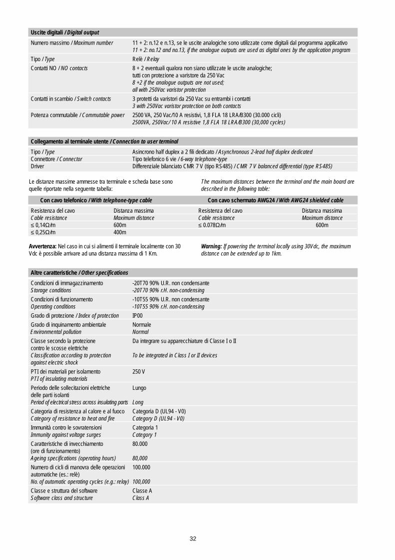
Le distanze massime ammesse tra terminale e scheda base sonoquelle riportate nella seguente tabella:
Avvertenza: Nel caso in cui si alimenti il terminale localmente con 30Vdc è possibile arrivare ad una distanza massima di 1 Km.
The maximum distances between the terminal and the main board aredescribed in the following table:
Warning: If powering the terminal locally using 30Vdc, the maximumdistance can be extended up to 1km.
32
Uscite digitali / Digital output
Numero massimo / Maximum number 11 + 2: n.12 e n.13, se le uscite analogiche sono utilizzate come digitali dal programma applicativo11 + 2: no.12 and no.13, if the analogue outputs are used as digital ones by the application program
Tipo / Type Relè / Relay
Contatti NO / NO contacts 8 + 2 eventuali qualora non siano utilizzate le uscite analogiche;tutti con protezione a varistore da 250 Vac8 +2 if the analogue outputs are not used;all with 250Vac varistor protection
Contatti in scambio / Switch contacts 3 protetti da varistori da 250 Vac su entrambi i contatti3 with 250Vac varistor protection on both contacts
Potenza commutabile / Commutable power 2500 VA, 250 Vac/10 A resistivi, 1,8 FLA 18 LRA/B300 (30.000 cicli)2500VA, 250Vac/ 10 A resistive 1,8 FLA 18 LRA/B300 (30,000 cycles)
Collegamento al terminale utente / Connection to user terminal
Tipo / Type Asincrono half duplex a 2 fili dedicato / Asynchronous 2-lead half duplex dedicatedConnettore / Connector Tipo telefonico 6 vie / 6-way telephone-type Driver Differenziale bilanciato CMR 7 V (tipo RS485) / CMR 7 V balanced differential (type RS485)
Con cavo telefonico / With telephone-type cable Con cavo schermato AWG24 / With AWG24 shielded cable
Resistenza del cavo Distanza massima Resistenza del cavo Distanza massimaCable resistance Maximum distance Cable resistance Maximum distance≤ 0,14Ω/m 600m ≤ 0.078Ω/m 600m≤ 0,25Ω/m 400m
Altre caratteristiche / Other specifications
Condizioni di immagazzinamento -20T70 90% U.R. non condensanteStorage conditions -20T70 90% r.H. non-condensing
Condizioni di funzionamento -10T55 90% U.R. non condensanteOperating conditions -10T55 90% r.H. non-condensing
Grado di protezione / Index of protection IP00
Grado di inquinamento ambientale NormaleEnvironmental pollution Normal
Classe secondo la protezione Da integrare su apparecchiature di Classe I o IIcontro le scosse elettricheClassification according to protection To be integrated in Class I or II devicesagainst electric shock
PTI dei materiali per isolamento 250 VPTI of insulating materials
Periodo delle sollecitazioni elettriche Lungodelle parti isolantiPeriod of electrical stress across insulating parts Long
Categoria di resistenza al calore e al fuoco Categoria D (UL94 - V0)Category of resistance to heat and fire Category D (UL94 - V0)
Immunità contro le sovratensioni Categoria 1Immunity against voltage surges Category 1
Caratteristiche di invecchiamento 80.000(ore di funzionamento)Ageing specifications (operating hours) 80,000
Numero di cicli di manovra delle operazioni 100.000automatiche (es.: relè)No. of automatic operating cycles (e.g.: relay) 100,000
Classe e struttura del software Classe ASoftware class and structure Class A
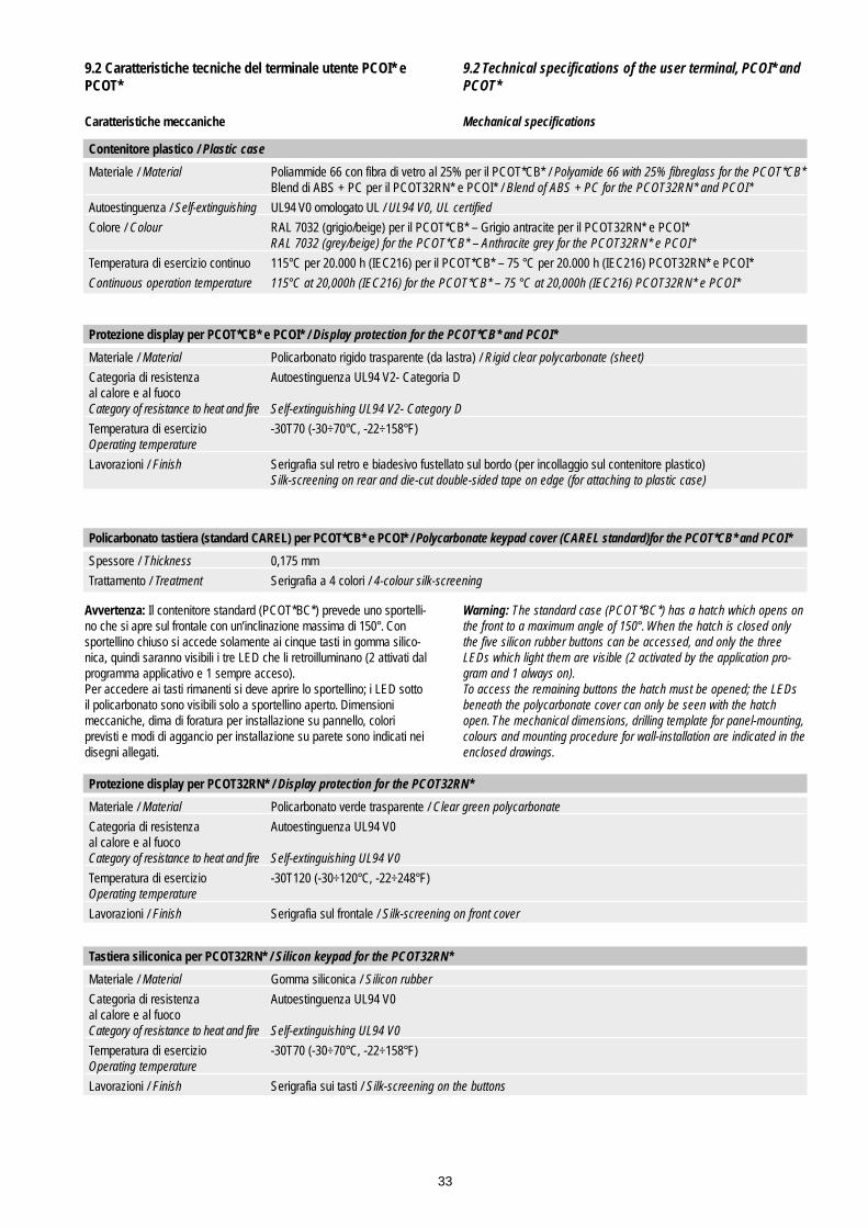
9.2 Caratteristiche tecniche del terminale utente PCOI* ePCOT*
Caratteristiche meccaniche
Avvertenza: Il contenitore standard (PCOT*BC*) prevede uno sportelli-no che si apre sul frontale con un’inclinazione massima di 150°. Consportellino chiuso si accede solamente ai cinque tasti in gomma silico-nica, quindi saranno visibili i tre LED che li retroilluminano (2 attivati dalprogramma applicativo e 1 sempre acceso).Per accedere ai tasti rimanenti si deve aprire lo sportellino; i LED sottoil policarbonato sono visibili solo a sportellino aperto. Dimensioni meccaniche, dima di foratura per installazione su pannello, colori previsti e modi di aggancio per installazione su parete sono indicati neidisegni allegati.
9.2 Technical specifications of the user terminal, PCOI* andPCOT*
Mechanical specifications
Warning: The standard case (PCOT*BC*) has a hatch which opens onthe front to a maximum angle of 150°. When the hatch is closed onlythe five silicon rubber buttons can be accessed, and only the threeLEDs which light them are visible (2 activated by the application pro-gram and 1 always on).To access the remaining buttons the hatch must be opened; the LEDsbeneath the polycarbonate cover can only be seen with the hatchopen. The mechanical dimensions, drilling template for panel-mounting,colours and mounting procedure for wall-installation are indicated in theenclosed drawings.
33
Contenitore plastico / Plastic case
Materiale / Material Poliammide 66 con fibra di vetro al 25% per il PCOT*CB* / Polyamide 66 with 25% fibreglass for the PCOT*CB*Blend di ABS + PC per il PCOT32RN* e PCOI* / Blend of ABS + PC for the PCOT32RN* and PCOI*
Autoestinguenza / Self-extinguishing UL94 V0 omologato UL / UL94 V0, UL certified
Colore / Colour RAL 7032 (grigio/beige) per il PCOT*CB* – Grigio antracite per il PCOT32RN* e PCOI*RAL 7032 (grey/beige) for the PCOT*CB* – Anthracite grey for the PCOT32RN* e PCOI*
Temperatura di esercizio continuo 115°C per 20.000 h (IEC216) per il PCOT*CB* – 75 °C per 20.000 h (IEC216) PCOT32RN* e PCOI*
Continuous operation temperature 115°C at 20,000h (IEC216) for the PCOT*CB* – 75 °C at 20,000h (IEC216) PCOT32RN* e PCOI*
Protezione display per PCOT*CB* e PCOI* / Display protection for the PCOT*CB* and PCOI*
Materiale / Material Policarbonato rigido trasparente (da lastra) / Rigid clear polycarbonate (sheet)
Categoria di resistenza Autoestinguenza UL94 V2- Categoria Dal calore e al fuocoCategory of resistance to heat and fire Self-extinguishing UL94 V2- Category D
Temperatura di esercizio -30T70 (-30÷70°C, -22÷158°F)Operating temperature
Lavorazioni / Finish Serigrafia sul retro e biadesivo fustellato sul bordo (per incollaggio sul contenitore plastico)Silk-screening on rear and die-cut double-sided tape on edge (for attaching to plastic case)
Policarbonato tastiera (standard CAREL) per PCOT*CB* e PCOI* / Polycarbonate keypad cover (CAREL standard)for the PCOT*CB* and PCOI*
Spessore / Thickness 0,175 mm
Trattamento / Treatment Serigrafia a 4 colori / 4-colour silk-screening
Protezione display per PCOT32RN* / Display protection for the PCOT32RN*
Materiale / Material Policarbonato verde trasparente / Clear green polycarbonate
Categoria di resistenza Autoestinguenza UL94 V0al calore e al fuocoCategory of resistance to heat and fire Self-extinguishing UL94 V0
Temperatura di esercizio -30T120 (-30÷120°C, -22÷248°F)Operating temperature
Lavorazioni / Finish Serigrafia sul frontale / Silk-screening on front cover
Tastiera siliconica per PCOT32RN* / Silicon keypad for the PCOT32RN*
Materiale / Material Gomma siliconica / Silicon rubber
Categoria di resistenza Autoestinguenza UL94 V0al calore e al fuocoCategory of resistance to heat and fire Self-extinguishing UL94 V0
Temperatura di esercizio -30T70 (-30÷70°C, -22÷158°F)Operating temperature
Lavorazioni / Finish Serigrafia sui tasti / Silk-screening on the buttons
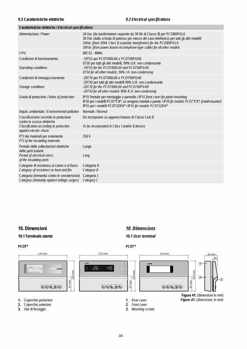
9.3 Caratteristiche elettriche
10. Dimensioni
10.1 Terminale utente
PCOT*
1. Coperchio posteriore2. Coperchio anteriore3. Vite di fissaggio
9.3 Electrical specifications
10. Dimensions
10.1 User terminal
PCOT*
1. Rear cover2. Front cover3. Mounting screws
34
Caratteristiche elettriche / Electrical specifications
Alimentazione / Power 24 Vac (da trasformatore separato da 30 VA di Classe II) per PCOI00PGL030 Vdc (dalla scheda di potenza per mezzo del cavo telefonico) per tutti gli altri modelli24Vac (from 30VA Class II separate transformer) for the PCOI00PGL030Vdc (from power board via telephone-type cable) for all other models
CPU 80C52 - 8MHz
Condizioni di funzionamento -10T55 per PCOT000L60 e PCOT00PGH00T50 per tutti gli altri modelli, 90% U.R. non condensante
Operating conditions -10T55 for the PCOT000L60 and PCOT00PGH00T50 for all other models, 90% r.H. non-condensing
Condizioni di immagazzinamento -20T70 per PCOT000L60 e PCOT00PGH0-20T50 per tutti gli altri modelli 90% U.R. non condensante
Storage conditions -20T70 for the PCOT000L60 and PCOT00PGH0-20T50 for all other models 90% R.H. non-condensing
Grado di protezione / Index of protection IP55 frontale per montaggio a pannello / IP55 front cover for panel-mountingIP20 per i modelli PCOT*CB*, se vengono montati a parete / IP20 for models PCOT*CB*, if wall-mountedIP55 per i modelli PCOT32RN* / IP55 for models PCOT32RN*
Inquin. ambientale / Environmental pollution Normale / Normal
Classificazione secondo la protezione Da incorporare su apparecchiature di Classe I e/o IIcontro le scosse elettricheClassification according to protection To be incorporated in Class I and/or II devicesagainst electric shock
PTI dei materiali per isolamento 250 VPTI of the insulating materials
Periodo delle sollecitazioni elettriche Lungodelle parti isolantiPeriod of electrical stress Longof the insulating parts
Categoria di resistenza al calore e al fuoco Categoria DCategory of resistance to heat and fire Category D
Categoria (immunità contro le sovratensioni) Categoria ICategory (immunity against voltage surges) Category I
170 mm
57 m
m11
4 m
m
GraphicRoom 1
Temp
on/off enteralarm
170 mm
57 m
m11
4 m
m
on/off enteralarm
170 mm 43 mm 20
57 m
m11
4 m
m
on/off enteralarm
A____
Parem
Psw
B____
Val
AL
1_ __________
2_ __________
3_ __________
4_ __________
5_ __________
1
23
Figura 41: (dimensioni in mm)Figure 41: (dimensions in mm)

PCOI*
PCOT32RN*
10.2 Tastiera e vetrinoDi seguito vengono riportati il vetrino ed il policarbonato della tastieradelle varie versioni del terminale pCO (dimensioni in mm):
PCOI*
PCOT32RN*
10.2 Keypad and window Following are the dimensions of the window and the polycarbonatekeypad cover for the various versions of the pCO terminal (dimensions in mm):
35
53 mm
43 mm
on/off alarm enter
pCO Terminal
menu I/O set prog.
?info
202 mm
177
mm
menu I/O set prog.
?info
on/off alarm enter
pCO Graphic
202 mm
177
mm
177
mm
Figura 42
75
33
dima di foraturadrilling template
71x29mm
fissaggio/overall dimensions 91.5x36.5mm
64
71,5
Figura 43
1_ ________
2_ ________
3_ ________
4_ ________
5_ ________
99
9
14.4
19.4
3.4
6.35
6.35
3.4
1650
7.25
9
37.212.537.2 2.6
2.5
16.4 14.727.5 49.5 70.7
166.7
43.1
1.7
11.5
32.5
5023
166.7
73.2
Vetrino terminale PCOT* con LCD 4x20Window for pCO terminal T* with 4x20 LCD
Vetrino terminale PCOT con 2x3 cifre a 7 segmentiWindow for pCO terminal T with 2x3 7-segment digits
Vetrino PCOT con display grafico 128 x 64Window for PCOT with 128 x 64 graphic display

Avvertenza: le quote riportate sopra sono espresse in mm.
10.3 Scheda base PCOB* In Figura 44 sono indicati i fori di fissaggio e le dimensioni della schedabase per il montaggio a quadro. I fori contraddistinti da una coroncinasono metallizzati e su questi vanno fissate le torrette metalliche colle-gate a loro volta alla terra del quadro.
Avvertenza: prima di eseguire ogni collegamento elettrico leggere iconsigli a pagina seguente e le note a pag.14.
Warning: all dimensions are expressed in mm.
10.3 Main board PCOB*Figure 44 shows the mounting holes and the dimensions of main boardfor mounting in electrical panels. The holes marked with an outer ringare metal-plated and are used for attaching the metal turrets, which inturn are connected to the earth of the electrical panel.
Warning: before performing any electrical connection see the followingpage and the notes on page 14.
36
169,6
31 64,6
35,3
37,8
97,1
R= 0,
7
169,6
22,4 122
6715
,5
97,1
R= 0,
7
Policarbonato del terminale PCOI* con LCD 4 x20Polycarbonate cover for the pCO terminal I* with 4 x20 LCD
Policarbonato del terminale PCOIPGL0 grafico 240 x 128Polycarbonate cover for the pCO IPGL0 240 x 128 graphic terminal
28.3
15 15 15 15 20.8
161.6
80.8
15.3 911 911 911 911 911 911 15.31120.8 20 20 20 20 20 20 20.8
80.8 80.8
3.318
14.3 13
.312
8.8
188.
835
.6
R=1.8
menu
?info
I/O set prog.
25,8 20 20 20 20 20 20 23,8
12 12 12 12 12 12 1219,8
20 20,1 20,1 20,1 20,1 20,1 20,1 29
15 15 15 15 23,885,8
169,6
14,8
5,5
12,5
5,5
11,3
49,6
1212
8,8
610
,8
8 8 8 8 8 8 17,8
16,8
6,3
76,8 15,4
Policarbonato della tastiera del terminale PCOT*Polycarbonate keypad cover for the pCO terminal T*
Policarbonato della tastiera del terminale PCOIPolycarbonate keypad cover for the pCO terminal I*
107
292
0
0
5.08
92.592.4
102.4
52.7
22.214.4
5.08
78.7
99.1
144.
1
160.
8
170
238.
1
276.
5
n.6 Ø 3.5 n.4 Ø 4.8
28
131
38
Figura 44: Dimensioni e fori di fissaggio scheda base (in mm)
Figure 44: Dimensions and mounting holes for the main board (in mm)

11. Montaggio terminale utente
11.1 Montaggio a pannello
PCOT*
PCOI*
11.2 Montaggio a parete
11. User Terminal mounting
11.1 Panel mounting
PCOT*
PCOI*
11.2 Wall-mounting
37
drilling template167 x 108mm
1
5
2
3
64
Riferimenti / Legenda (Fig. 45)1. Coperchio posteriore / Rear cover2. Pannello / Panel3. Coperchio anteriore / Front cover4. Dime di foratura (tolleranza finestra: -0,5÷ +1 mm
sulle dimensioni indicate) / Drilling template (tolerance: -0.5÷ +1 mm on the indicated dimensions)
5. Guarnizione per coperchio posteriore / Rear cover gasket6. Guarnizione per coperchio anteriore / Front cover gasket
Fig. 45
drilling template173 x 154mm
124m
m
181.5mm
15m
m
4.25mm
Ø 2.5mm
15m
m
154m
m
173mm2
3
1
5
4
Fig. 46
84 mm
80 m
m
120 mm
==
2
3
1
1
Riferimenti / Legenda (Fig. 46)1. Cornice esterna / External frame2. Pannello / Panel3. Terminale / Terminal4. Dime di foratura (tolleranza finestra: -0,5÷ +0,5 mm
Drilling template (tolerance: -0.5÷+0.5 mm)5. Guarnizione frontale / Front cover gasket
Avvertenza: lo spessore massimo del pannello deve esseredi 6 mm.Warning: the maximum thickness of the panel is 6 mm.
Il montaggio a parete prevede l’utilizzo di un’apposita staffa di fissaggio e di una scatola da parete standard a 3moduli per interruttori al fine di consentire il passaggiodei cavi. Fissare la staffa (1) alla parete (3) utilizzando lavite (2); incastrare il dorso dello strumento alla staffa.
Wall-mounting requires the use of a special mountingbracket and a standard 3-module switchbox for the passage of the cables. Fasten the bracket (1) to the wall(3) using the screws (2); clip the rear of the instrumentonto the bracket.
Fig. 47

12. Connessioni elettricheDi seguito viene indicato il collegamento del pCO ai vari dispositivi.
(*) Solo su schede con 8 ingressi analogici (cod.PCOB000**1).
Carel si riserva la possibilità di apportare modifiche o cambiamenti aipropri prodotti senza alcun preavviso.
12. Electrical connections The following diagram shows the connections of the pCO to the variousdevices.
(*) Only for boards with 8 analogue inputs (code PCOB000**1).
Carel reserves the right to modify its products without prior notice.
38
J17
J11
J20
J21
J22
J24
J1J2
J3J4
J5J6
B8+24VdcB7
B6
AVSS
B5
B4
AVSS
B3
B2
AVSS
B1
IDCM2
ID10
ID9
ID8
ID7
ID6
IDCM1
ID5
ID4
ID3
ID2
ID1
C1
NO1
-------
C2
NO2
C3
NO3
-------
C4
NO4
-------
C5
NO5
-------
C12
NO12
NO8
C8
-------
NO7
C7
-------
NO6
C6
-------
NO13
C13
NO11
C11
NC11
--------
NO10
C10
NC10
--------
NO9
C9
NC9
ID230
ID24
ID11R
--------
ID12R
ID24
ID230
VG0
VG1
Y1
Y0
GNDRX/TX-RX/TX+
GG0
J19
J14
J15
J28
J29
J9 J8
Analogue output 1 (0+10Vdc)
Analogue output 2 (0+10Vdc)
Digital output 11
Digital output 10
Digital output 9
Digital output 8
Digital output 7
Digital output 6
Digital output 13
Digital input 12 (230 Vac)
Digital input 11 (230 Vac)
M V+OUT
Digital output 1
Digital output 2
Digital output 3
Digital output 4
Digital output 5
Digital output 12
Digital input 10Digital input 9Digital input 8Digital input 7Digital input 6
Digital input 5Digital input 4Digital input 3Digital input 2Digital input 1
Probe 8 (*)
Probe 7 (*)Probe 5(0 1Vdc o 4 20mA)Probe 6(0 1Vdc o 4 20mA)
Carel NTC probe 4
Carel NTC probe 3Carel NTC probe 2
Carel NTC probe 1
G
G0
L
N
230/24 Vac
Fig. 48


Cod
. +
0302
2185
0 r
el.
3.3
– de
l 05/
04/2
000
Agency:
CAREL srl Via dell’Industria, 11 - 35020 Brugine - Padova (Italy)Tel. (+39) 0499716611 – Fax (+39) 0499716600http://www.carel.com – e-mail: [email protected]