
Sperimentazione di un impianto pilota MBR per il trattamento dei reflui tessili di Seano (PO)
Upload
nguyenliemCategory
view
216download
0
Sistemi Operativi
Lez. 17/18/19 Il bootstrap
Copyright
• Il materiale presentato nelle prossime lezioni è basato sul sistema operativo JOS sviluppato come attività di laboratorio nell’ambito del corso “ 6.828 Operating System Engineering” erogato dal MIT
• http://pdos.csail.mit.edu/6.828/2012/index.html
A.A. 2014/2015 Corso: Sistemi Operativi © Danilo Bruschi
2
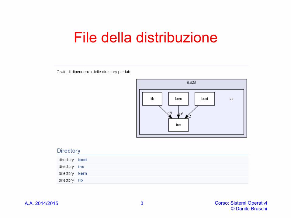
File della distribuzione
A.A. 2014/2015 Corso: Sistemi Operativi © Danilo Bruschi
3
bootstrap
• Tutti calcolatori hanno lo stesso problema, sanno solo eseguire le istruzioni contenute nel programma in esecuzione
• Ma all’accensione di un sistema, in memoria non è presente alcun programma
• Come facciamo a predisporre un calcolatore ad eseguire programmi?
A.A. 2014/2015 Corso: Sistemi Operativi © Danilo Bruschi
4

bootstrap
• I calcolatori moderni fanno ricorso ad una ROM in cui è memorizzato il codice iniziale per avviare il caricamento del sistema operativo, operazione nota con il termine boot loading
• Attualmente ci sono due categorie di boot loader: • Basati di BIOS Basic Input/output System • Basati su EFI/UEFI [Unified] Extensbile Firmware Interface
A.A. 2014/2015 Corso: Sistemi Operativi © Danilo Bruschi
5
BIOS
A.A. 2014/2015 Corso: Sistemi Operativi © Danilo Bruschi
6
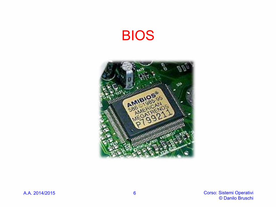
BIOS • The BIOS is software stored on a permanent memory
chip attached to the motherboard (firmware). The modern chip used is refered to as an EEPROM - Electrically Erasable Programmable Read Only Memory
• The four main software components of the BIOS program code are: • the BIOS built in 16-bit device drivers for all standard
peripheral components • the BIOS CMOS Setup Utility • the POST - Power On Self Test • the BIOS Boot Strap Loader
• Besides that BIOS built its own IDT table for managing interrrupt from I/O devices
A.A. 2014/2015 Corso: Sistemi Operativi © Danilo Bruschi
7
Drivers
• The BIOS 16-bit device drivers present a universal set of functions for accessing standard devices built into any motherboard regardless of how that hardware specifically works
• This is called the BIOS API - Application Programmer's Interface which IBM published so that anyone could write software that would work on any PC
• The BIOS functions are very limited and very low level
A.A. 2014/2015 Corso: Sistemi Operativi © Danilo Bruschi
8
CMOS Utility
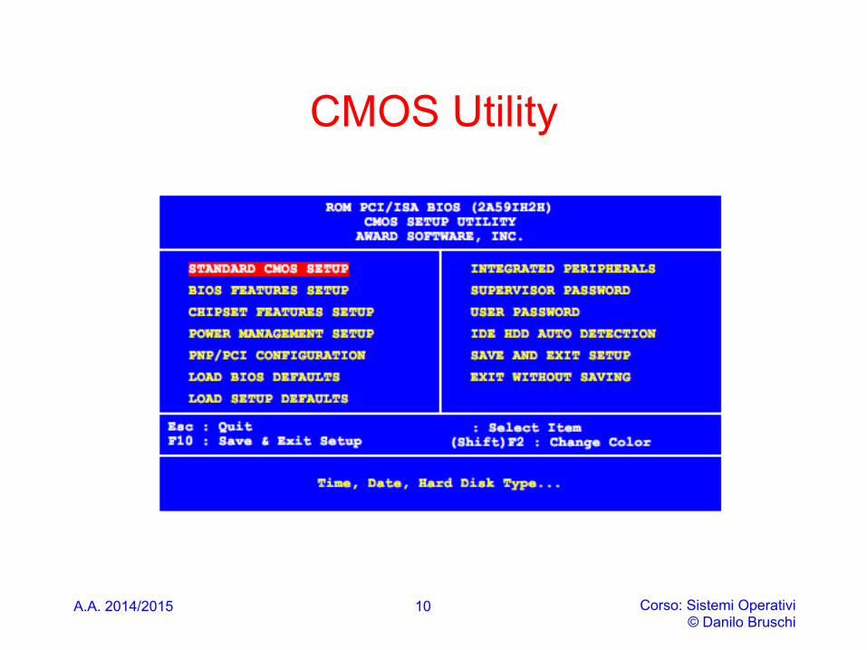
• The BIOS Setup Utility is a menu driven program built into the BIOS code which allows the user to inspect and modify the hardware configuration settings held in the CMOS RAM
• This section of the BIOS normally does not execute during a routine start up
• During the POST of the system you can enter the BIOS CMOS Setup Utility by pressing the correct key or combination of keys.
A.A. 2014/2015 Corso: Sistemi Operativi © Danilo Bruschi
9
CMOS Utility
A.A. 2014/2015 Corso: Sistemi Operativi © Danilo Bruschi
10

A.A. 2014/2015 Corso: Sistemi Operativi © Danilo Bruschi
Bootstrap (Sw Developer Manual – Cap. 9)
• The process begins when the power supply is switched on • The power supply performs a self-test:
• When all voltages and current levels are acceptable (+5v, +3.0 through +6.0 is generally considered acceptable), the supply indicates that the power is stable and sends the "Power Good" signal to the motherboard.
• The "Power Good" signal is received by the microprocessor timer chip, which controls the reset line to the microprocessor. The time between turning on the switch to the generation of the "Power Good" signal is usually between 0.1 and 0.5 seconds.
• In the absence of the "Power Good" signal, the timer chip continuously resets the microprocessor, which prevents the system from running under bad or unstable power conditions
• The microprocessor timer chip receives the "Power Good" signal: • After the power supply is switched on, the microprocessor timer chip generates a reset
signal to the processor (the same as if you held the reset button down for a while on your case) until it receives the "Power Good" signal from the power supply.
• Following power-up or an assertion of the RESET# pin, each processor on the system bus performs a hardware initialization (known as a hardware reset) and an optional built-in self-test (BIST)
11

Bootstrap
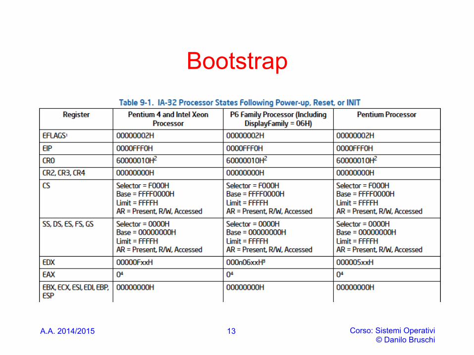
• Table 9-1 shows the state of the flags and other registers following power-up for the Pentium 4, Intel Xeon, P6 family (including Intel processors with CPUID Display Family signature of 06H), and Pentium processors. The state of control register CR0 is 60000010H (see Figure 9-1). This places the processor in real-address mode with paging disabled.
A.A. 2014/2015 Corso: Sistemi Operativi © Danilo Bruschi
12
Bootstrap
A.A. 2014/2015 Corso: Sistemi Operativi © Danilo Bruschi
13
Memory map
A.A. 2014/2015 Corso: Sistemi Operativi © Danilo Bruschi
14
First instruction executed (8088)
• The first instruction that is fetched and executed following a hardware reset is located at physical address 0xFFFF0. This address is 16 bytes below the processor’s uppermost 20-bit physical address. The EPROM containing the software initialization code must be located at this address
• The processor is initialized to this starting address as follows: during a hardware reset, the segment selector in the CS register is loaded with 0xF000 and EIP to 0xFFF0 . The starting address is thus formed by using these two addresses (see slide 22)
• This is the address where the first BIOS instruction is stored
A.A. 2014/2015 Corso: Sistemi Operativi © Danilo Bruschi
15
POST • The POST code starts by scanning for offboard
BIOS'es and if it finds any it will immediately pass control to them.
• After control returns to the POST it will test all of the immediate chipset members that are in direct contact with the CPU and upon which it depends such as the Dynamic RAM controller which organizes RAM banks and controls the refresh of the RAM memory cells and the relocatable address demultiplexing.
• Another close and important chip is the expansion bus controller. The POST proceeds on to test the peripheral devices attached to the expansion buses
A.A. 2014/2015 Corso: Sistemi Operativi © Danilo Bruschi
16
Boot loader • So if all of the devices respond properly then the system has
successfully passed the POST and then the POST will issue a single beep from the system speaker
• Then the POST code will jump to the next embedded program component of the BIOS code: the BIOS Boot Strap Loader code
• Loading the OS (Operating System):The BIOS will attempt booting using the boot sequence determined by the CMOS settings, and examine the MBR (Master Boot Record) of the bootable disk.
• The MBR is the information in the first sector (512 bytes) of any hard disk or diskette that identifies how and where an operating system is located so that it can be loaded into the RAM (booted).
• When the BIOS finds a bootable floppy or hard disk, it loads the 512-byte boot sector into memory at physical addresses 0x7c00 through 0x7dff
A.A. 2014/2015 Corso: Sistemi Operativi © Danilo Bruschi
17
Bootloading & MBR
• Picture is made more complex by hard disk partitioning • First sector of a hard disk is a master boot record (MBR) • Specifies up to four partitions of the hard disk, each with
its own format and use • e.g. each partition could be used for a different operating system • An operating system might also need multiple partitions, e.g.
Linux filesystem partition vs. Linux swap partition • Issue: MBR doesn’t correspond to a specific operating
system; the disk may contain multiple OSes! • A partition containing an operating system often specifies
its own bootloader in the first sector of the partition • MBR must kick off the next bootloader in the process...
A.A. 2014/2015 Corso: Sistemi Operativi © Danilo Bruschi
18
MBR e bootloading
• MBR loader must load a partition bootloader... • Must do it in such a way that the partition bootloader
doesn’t know it wasn’t loaded directly by the BIOS • MBR loader must emulate the BIOS bootloading mechanism
• MBR loaders use a mechanism called chain loading • MBR loads the next bootloader into address 0x7C00,
then jumps to that address and begins running it • Of course, the MBR loader was loaded at 0x7C00...
• Must first copy itself to another location, then jump there before carrying on next tasks
• Chain loaders often copy themselves to address 0x0600
Corso: Sistemi Operativi © Danilo Bruschi
19 A.A. 2014/2015
EFI
• Intel plans to replace the (very) old BIOS system with a new set of programs
• The new system is called EFI (Extensible Firmware Interface) and is in itself a complete little operating system
• It has a graphical user interface. Where the old BIOS is written in the Assempler language, the new EFI is written in C, making it more easy accessable
A.A. 2014/2015 Corso: Sistemi Operativi © Danilo Bruschi
20
BOOT LOADER (QEMU 8088)
A.A. 2014/2015 Corso: Sistemi Operativi © Danilo Bruschi
21
A.A. 2014/2015 Corso: Sistemi Operativi © Danilo Bruschi
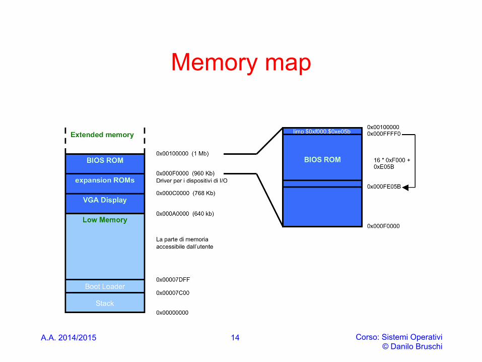
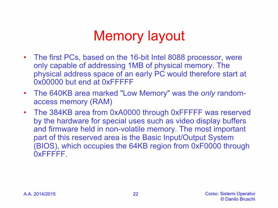
Memory layout • The first PCs, based on the 16-bit Intel 8088 processor, were
only capable of addressing 1MB of physical memory. The physical address space of an early PC would therefore start at 0x00000 but end at 0xFFFFF
• The 640KB area marked "Low Memory" was the only random-access memory (RAM)
• The 384KB area from 0xA0000 through 0xFFFFF was reserved by the hardware for special uses such as video display buffers and firmware held in non-volatile memory. The most important part of this reserved area is the Basic Input/Output System (BIOS), which occupies the 64KB region from 0xF0000 through 0xFFFFF.
22
A.A. 2014/2015 Corso: Sistemi Operativi © Danilo Bruschi
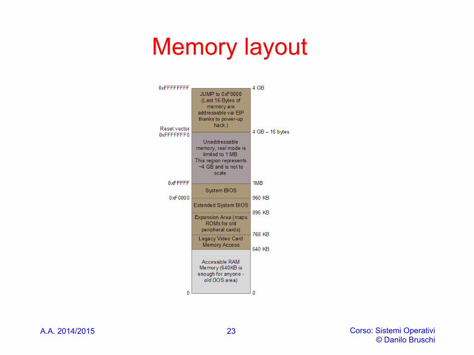
Memory layout
23
A.A. 2014/2015 Corso: Sistemi Operativi © Danilo Bruschi
Memory layout
• When Intel finally "broke the one megabyte barrier" with the 80286 and 80386 processors, which supported 16MB and 4GB physical address spaces respectively, the PC architects nevertheless preserved the original layout for the low 1MB of physical address space in order to ensure backward compatibility with existing software.
• Modern PCs therefore have a "hole" in physical memory from 0x000A0000 to 0x00100000, dividing RAM into "low" or "conventional memory" (the first 640KB) and "extended memory" (everything else).
24
Real mode
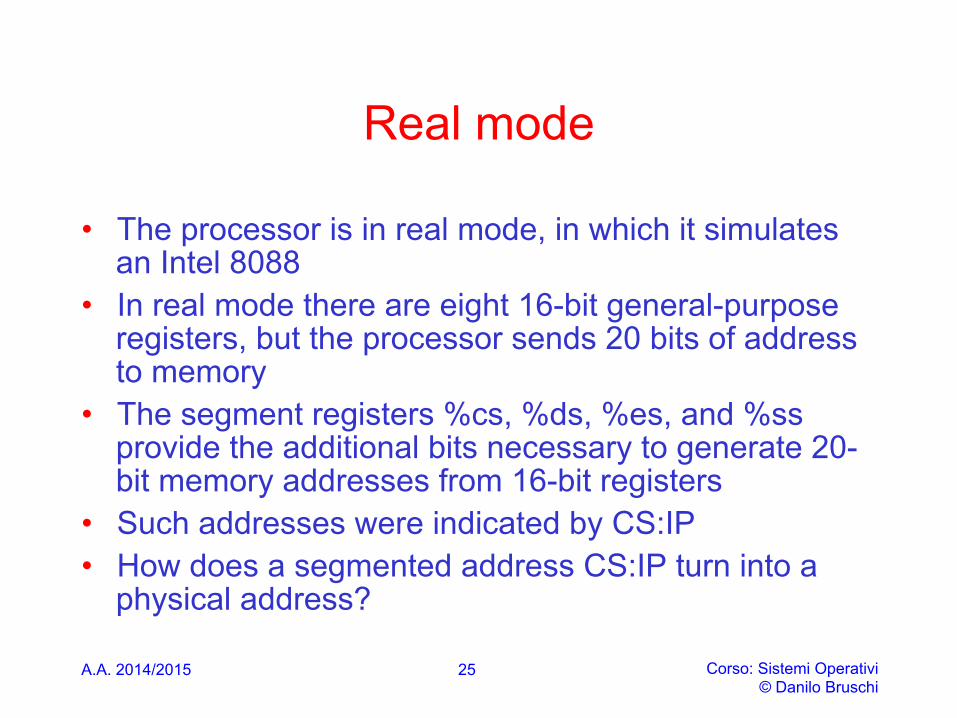
• The processor is in real mode, in which it simulates an Intel 8088
• In real mode there are eight 16-bit general-purpose registers, but the processor sends 20 bits of address to memory
• The segment registers %cs, %ds, %es, and %ss provide the additional bits necessary to generate 20-bit memory addresses from 16-bit registers
• Such addresses were indicated by CS:IP • How does a segmented address CS:IP turn into a
physical address?
A.A. 2014/2015 Corso: Sistemi Operativi © Danilo Bruschi
25
Real mode address translation
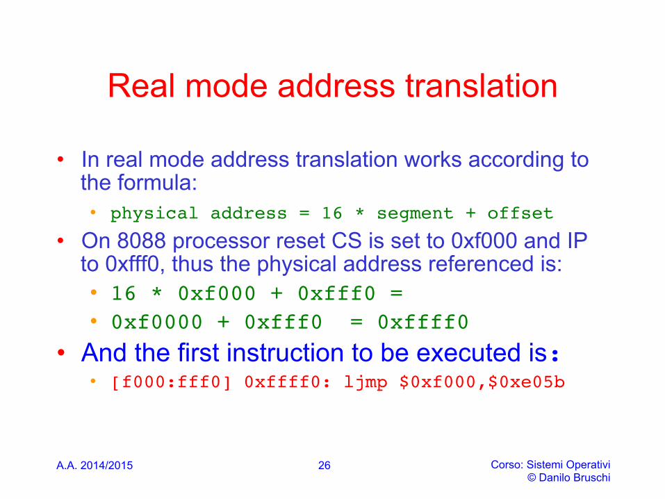
• In real mode address translation works according to the formula: • physical address = 16 * segment + offset
• On 8088 processor reset CS is set to 0xf000 and IP to 0xfff0, thus the physical address referenced is: • 16 * 0xf000 + 0xfff0 = • 0xf0000 + 0xfff0 = 0xffff0
• And the first instruction to be executed is:• [f000:fff0] 0xffff0: ljmp $0xf000,$0xe05b
A.A. 2014/2015 Corso: Sistemi Operativi © Danilo Bruschi
26
A.A. 2014/2015 Corso: Sistemi Operativi © Danilo Bruschi
BIOS • When the BIOS runs, it sets up an interrupt descriptor table and
initializes various devices such as the VGA display. • After initializing the PCI bus and all the important devices the
BIOS knows about, it searches for a bootable device such as a floppy, hard drive, or CD-ROM. Eventually, when it finds a bootable disk, the BIOS reads the boot loader from the disk and transfers control to it
• If the disk is bootable, the first sector is called the boot sector, since this is where the boot loader code resides. When the BIOS finds a bootable floppy or hard disk, it loads the 512-byte boot sector into memory at physical addresses 0x7c00 through 0x7dff, and then uses a jmp instruction to set the CS:IP to 0000:7c00, passing control to the boot loader. Like the BIOS load address, these addresses are fairly arbitrary - but they are fixed and standardized for PCs.
27
A.A. 2014/2015 Corso: Sistemi Operativi © Danilo Bruschi
Boot Loader
• BEGIN 1. enables address line 20; 2. switches the processor from real mode to 32-bit
protected mode, in this mode software can access all the memory above 1MB in the processor's physical address space, the boot loader does not enable the paging hardware, only segmentation;
3. reads the kernel from the hard disk by directly
accessing the IDE disk device registers via the x86's special I/O instructions;
• END 28
ENABLE A20 ADDRESS LINE
A.A. 2014/2015 Corso: Sistemi Operativi © Danilo Bruschi
29
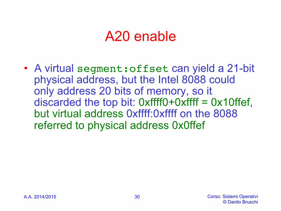
A20 enable
• A virtual segment:offset can yield a 21-bit physical address, but the Intel 8088 could only address 20 bits of memory, so it discarded the top bit: 0xffff0+0xffff = 0x10ffef, but virtual address 0xffff:0xffff on the 8088 referred to physical address 0x0ffef
A.A. 2014/2015 Corso: Sistemi Operativi © Danilo Bruschi
30

A20 enable
• Some early software relied on the hardware ignoring the 21st address bit, so during bootup, the BIOS enables the A20 line to test the memory
• After the memory test, the BIOS disables the A20 line to retain compatability with older processors. Because of this, by default, the A20 line is disabled for our operating system
• so the operating system has to find out how to enable it, and that may be nontrivial since the details depend on the chipset used
A.A. 2014/2015 Corso: Sistemi Operativi © Danilo Bruschi
31
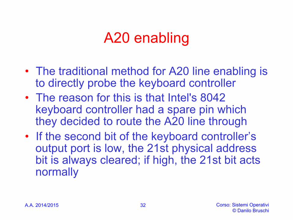
A20 enabling
• The traditional method for A20 line enabling is to directly probe the keyboard controller
• The reason for this is that Intel's 8042 keyboard controller had a spare pin which they decided to route the A20 line through
• If the second bit of the keyboard controller’s output port is low, the 21st physical address bit is always cleared; if high, the 21st bit acts normally
A.A. 2014/2015 Corso: Sistemi Operativi © Danilo Bruschi
32
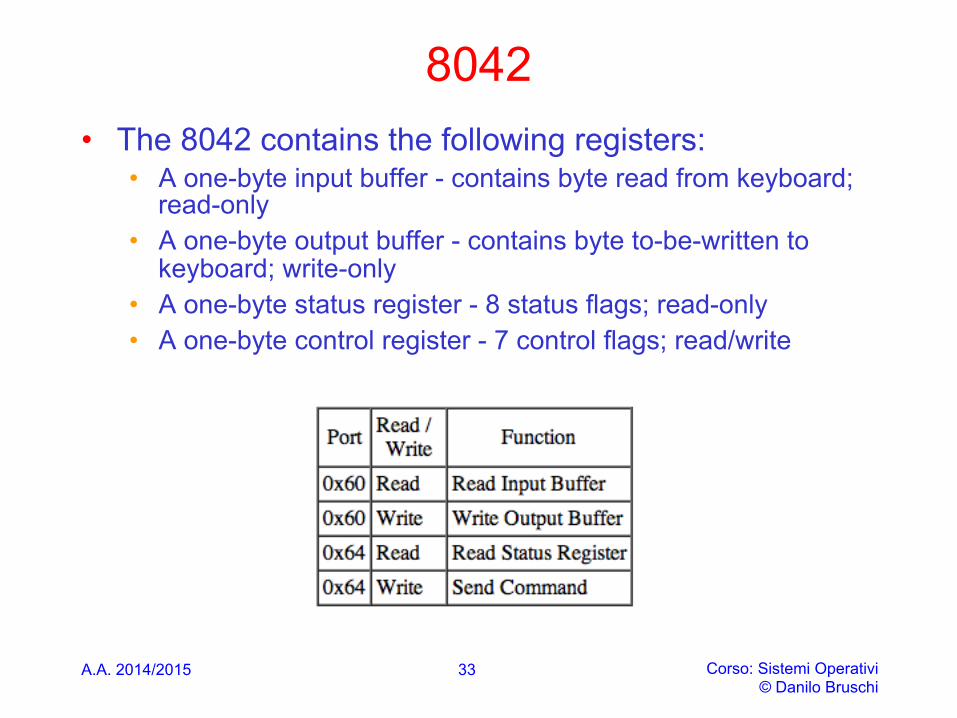
8042 • The 8042 contains the following registers:
• A one-byte input buffer - contains byte read from keyboard; read-only
• A one-byte output buffer - contains byte to-be-written to keyboard; write-only
• A one-byte status register - 8 status flags; read-only • A one-byte control register - 7 control flags; read/write
A.A. 2014/2015 Corso: Sistemi Operativi © Danilo Bruschi
33
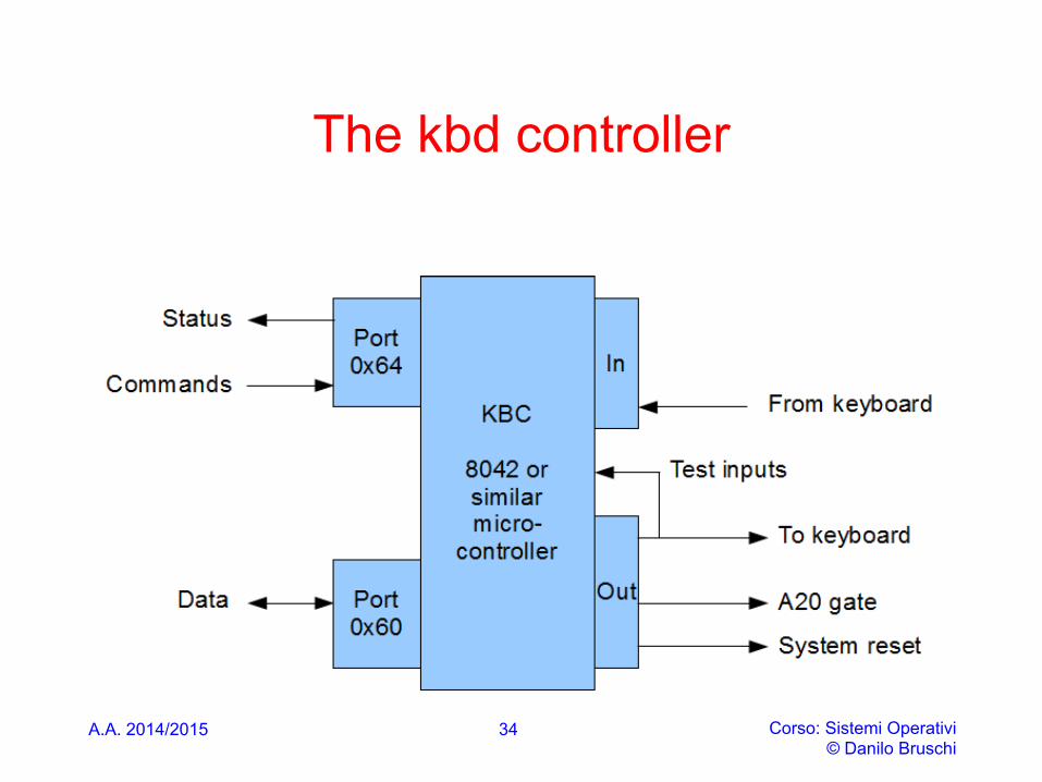
The kbd controller
A.A. 2014/2015 Corso: Sistemi Operativi © Danilo Bruschi
34
A20 enable
• The output port (or output buffer) of the keyboard controller has a number of functions. • Bit 0 is used to reset the CPU (go to real mode) - a
reset happens when bit 0 is 0 • Bit 1 is used to control A20 - it is enabled when bit
1 is equal to 1, disabled when bit 1 is equal to 0
A.A. 2014/2015 Corso: Sistemi Operativi © Danilo Bruschi
35
Writing to output port
• In order to write to output port: 1. A “Write output port” command i.e. 0xD1 has to
be sent to the controller, this means that 0xD1 has to be “out” to port 0x64 (send a command),
2. The data to be inserted in the output port has be be written on port 0x60
• Before executing the above mentioned commands, a cycle for verifying whether the kyboard is ready has to be performed
A.A. 2014/2015 Corso: Sistemi Operativi © Danilo Bruschi
36

A.A. 2014/2015 Corso: Sistemi Operativi © Danilo Bruschi
boot.s
# Enable A20: # For backwards compatibility with the earliest PCs, physical # address line 20 is tied low, so that addresses higher than # 1MB wrap around to zero by default. This code undoes this. seta20.1: inb $0x64,%al # Wait for not busy testb $0x2,%al jnz seta20.1 movb $0xd1,%al # 0xd1 -> port 0x64 outb %al,$0x64 seta20.2: inb $0x64,%al # Wait for not busy testb $0x2,%al jnz seta20.2 movb $0xdf,%al # 0xdf -> port 0x60 outb %al,$0x60
37
ENABLE PROT. MODE (SEGMENTED ONLY)
A.A. 2014/2015 Corso: Sistemi Operativi © Danilo Bruschi
38
SW inizialization for protected mode
• The processor is placed in real-address mode following a hardware reset. At this point in the initialization process, some basic data structures and code modules must be loaded into physical memory to support further initialization of the processor
• Before the processor can be switched to protected mode, the software initialization code must load a minimum number of protected mode data structures and code modules into memory to support reliable operation of the processor in protected mode
• Initially we will just enable segmented protected mode, the data structures to be initialized in such a case represent a minimal subset of those related to paged protected mode
A.A. 2014/2015 Corso: Sistemi Operativi © Danilo Bruschi
39
SW inizialization for protected mode
• These data structures are: • IDT • GDT • TSS • (Optional) An LDT • If paging is to be used, at least one page directory and one
page table • A code segment that contains the code to be executed when
the processor switches to protected mode • One or more code modules that contain the necessary
interrupt and exception handlers
A.A. 2014/2015 Corso: Sistemi Operativi © Danilo Bruschi
40
Registers initialization
• Software initialization code must also initialize the following system registers before the processor can be switched to protected mode: • The GDTR. • (Optional.) The IDTR. This register can also be initialized
immediately after switching to protected mode, prior to enabling interrupts.
• Control registers CR1 through CR4.
A.A. 2014/2015 Corso: Sistemi Operativi © Danilo Bruschi
41
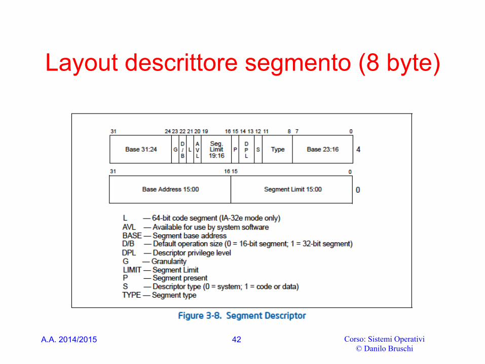
Layout descrittore segmento (8 byte)
A.A. 2014/2015 Corso: Sistemi Operativi © Danilo Bruschi
42
A.A. 2014/2015 Corso: Sistemi Operativi © Danilo Bruschi
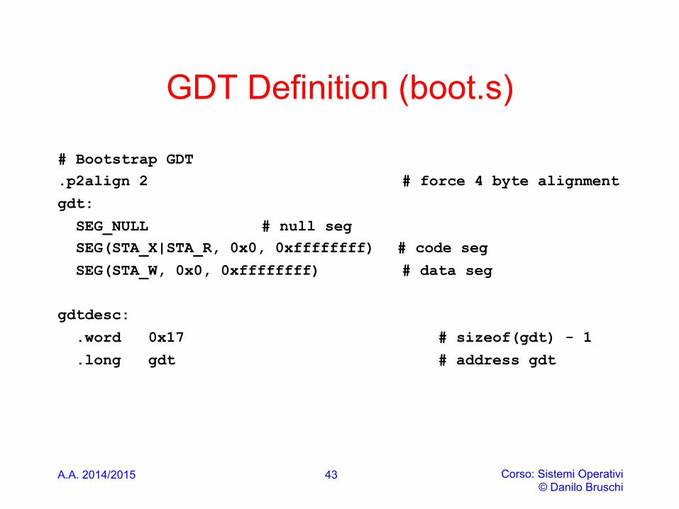
GDT Definition (boot.s)
# Bootstrap GDT .p2align 2 # force 4 byte alignment
gdt:
SEG_NULL # null seg SEG(STA_X|STA_R, 0x0, 0xffffffff) # code seg
SEG(STA_W, 0x0, 0xffffffff) # data seg
gdtdesc:
.word 0x17 # sizeof(gdt) - 1
.long gdt # address gdt
43
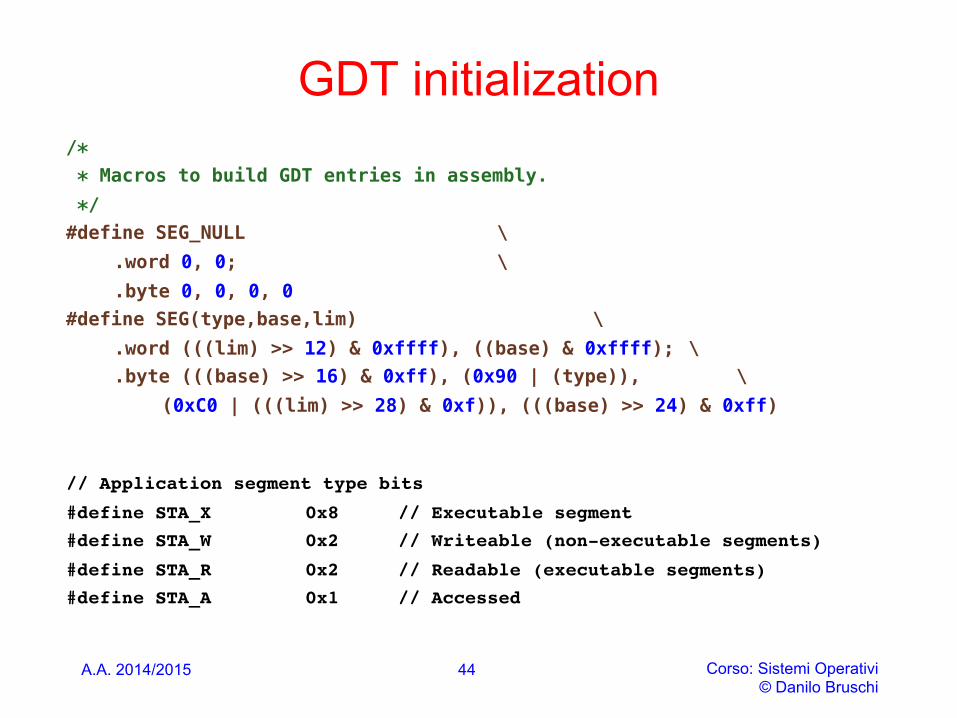
GDT initialization /* ! * Macros to build GDT entries in assembly. ! */ !#define SEG_NULL \ !
.word 0, 0; \ !
.byte 0, 0, 0, 0 !#define SEG(type,base,lim) \ !
.word (((lim) >> 12) & 0xffff), ((base) & 0xffff); \ !
.byte (((base) >> 16) & 0xff), (0x90 | (type)), \ !(0xC0 | (((lim) >> 28) & 0xf)), (((base) >> 24) & 0xff) !
!// Application segment type bits
#define STA_X 0x8 // Executable segment
#define STA_W 0x2 // Writeable (non-executable segments)
#define STA_R 0x2 // Readable (executable segments)
#define STA_A 0x1 // Accessed
A.A. 2014/2015 Corso: Sistemi Operativi
© Danilo Bruschi
44
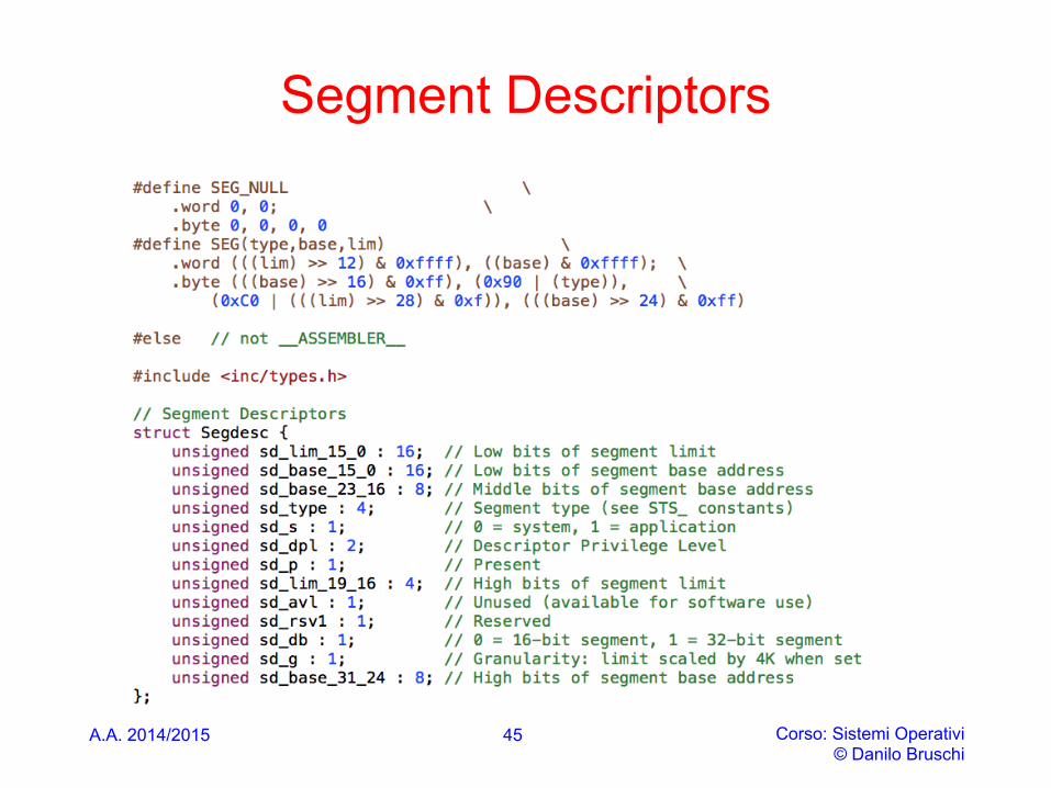
Segment Descriptors
A.A. 2014/2015 Corso: Sistemi Operativi © Danilo Bruschi
45
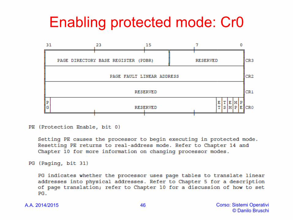
Enabling protected mode: Cr0
A.A. 2014/2015 Corso: Sistemi Operativi © Danilo Bruschi
46
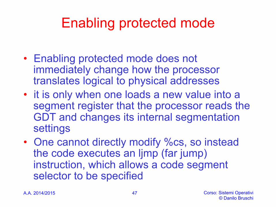
Enabling protected mode
• Enabling protected mode does not immediately change how the processor translates logical to physical addresses
• it is only when one loads a new value into a segment register that the processor reads the GDT and changes its internal segmentation settings
• One cannot directly modify %cs, so instead the code executes an ljmp (far jump) instruction, which allows a code segment selector to be specified
A.A. 2014/2015 Corso: Sistemi Operativi © Danilo Bruschi
47

Enabling protected mode
• The ljump continues execution so sets %cs to refer to the code descriptor entry in gdt
• That descriptor describes a 32-bit code segment, so the processor switches into 32-bit mode
A.A. 2014/2015 Corso: Sistemi Operativi © Danilo Bruschi
48
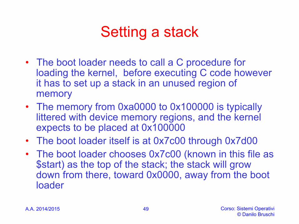
Setting a stack
• The boot loader needs to call a C procedure for loading the kernel, before executing C code however it has to set up a stack in an unused region of memory
• The memory from 0xa0000 to 0x100000 is typically littered with device memory regions, and the kernel expects to be placed at 0x100000
• The boot loader itself is at 0x7c00 through 0x7d00 • The boot loader chooses 0x7c00 (known in this file as
$start) as the top of the stack; the stack will grow down from there, toward 0x0000, away from the boot loader
A.A. 2014/2015 Corso: Sistemi Operativi © Danilo Bruschi
49
A.A. 2014/2015 Corso: Sistemi Operativi © Danilo Bruschi
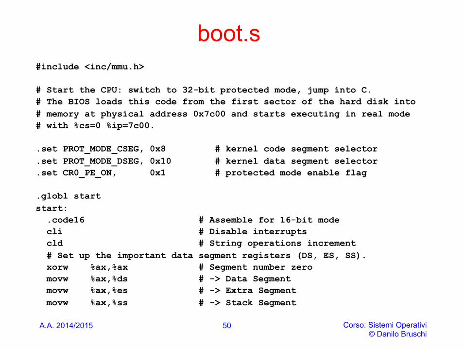
boot.s #include <inc/mmu.h> # Start the CPU: switch to 32-bit protected mode, jump into C. # The BIOS loads this code from the first sector of the hard disk into # memory at physical address 0x7c00 and starts executing in real mode # with %cs=0 %ip=7c00. .set PROT_MODE_CSEG, 0x8 # kernel code segment selector .set PROT_MODE_DSEG, 0x10 # kernel data segment selector .set CR0_PE_ON, 0x1 # protected mode enable flag .globl start start: .code16 # Assemble for 16-bit mode cli # Disable interrupts cld # String operations increment # Set up the important data segment registers (DS, ES, SS). xorw %ax,%ax # Segment number zero movw %ax,%ds # -> Data Segment movw %ax,%es # -> Extra Segment movw %ax,%ss # -> Stack Segment
50
A.A. 2014/2015 Corso: Sistemi Operativi © Danilo Bruschi
boot.s
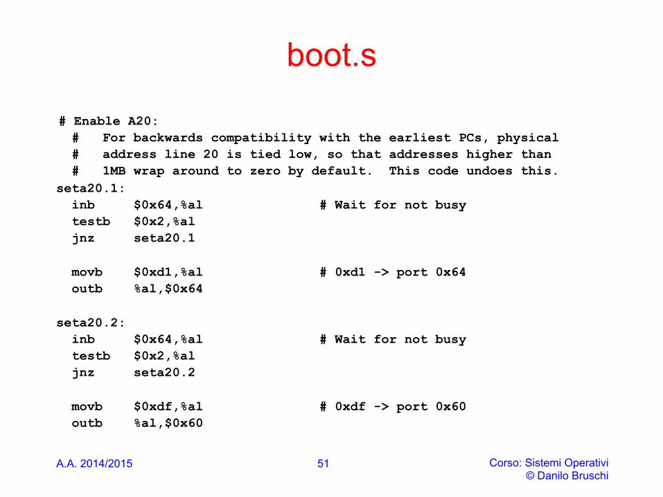
# Enable A20: # For backwards compatibility with the earliest PCs, physical # address line 20 is tied low, so that addresses higher than # 1MB wrap around to zero by default. This code undoes this. seta20.1: inb $0x64,%al # Wait for not busy testb $0x2,%al jnz seta20.1 movb $0xd1,%al # 0xd1 -> port 0x64 outb %al,$0x64 seta20.2: inb $0x64,%al # Wait for not busy testb $0x2,%al jnz seta20.2 movb $0xdf,%al # 0xdf -> port 0x60 outb %al,$0x60
51
A.A. 2014/2015 Corso: Sistemi Operativi © Danilo Bruschi
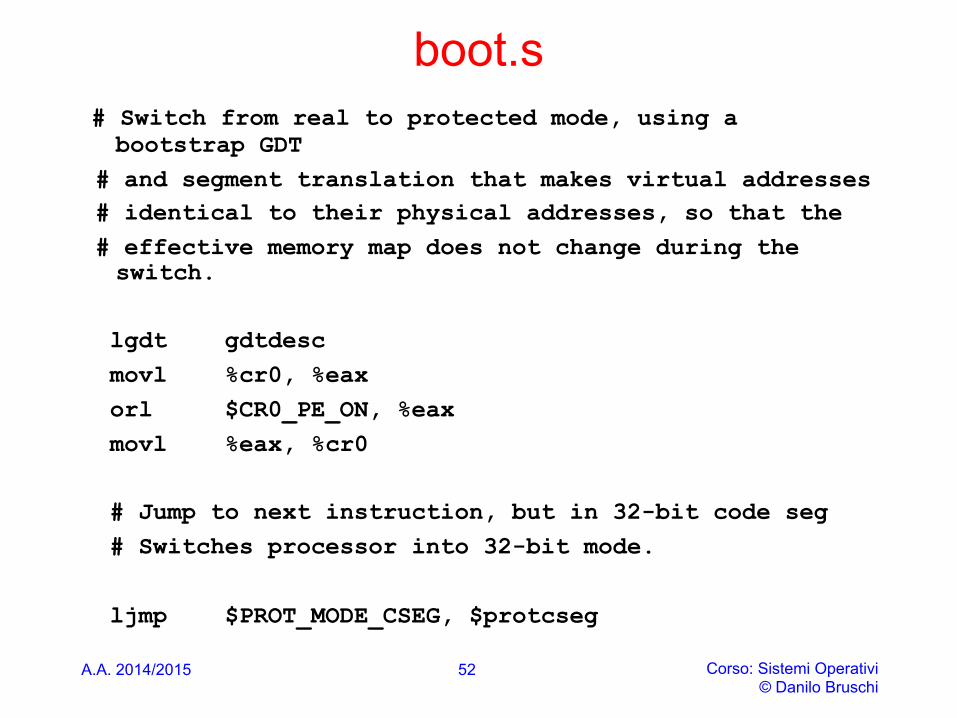
boot.s # Switch from real to protected mode, using a
bootstrap GDT # and segment translation that makes virtual addresses # identical to their physical addresses, so that the # effective memory map does not change during the
switch. lgdt gdtdesc movl %cr0, %eax orl $CR0_PE_ON, %eax movl %eax, %cr0 # Jump to next instruction, but in 32-bit code seg # Switches processor into 32-bit mode. ljmp $PROT_MODE_CSEG, $protcseg
52
A.A. 2014/2015 Corso: Sistemi Operativi © Danilo Bruschi
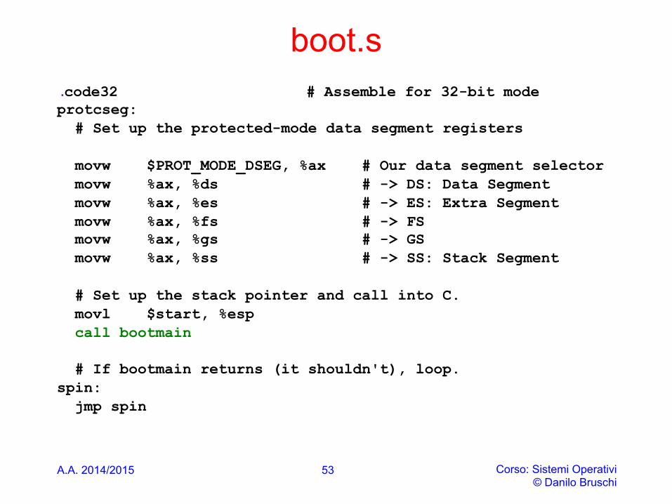
boot.s .code32 # Assemble for 32-bit mode protcseg: # Set up the protected-mode data segment registers movw $PROT_MODE_DSEG, %ax # Our data segment selector movw %ax, %ds # -> DS: Data Segment movw %ax, %es # -> ES: Extra Segment movw %ax, %fs # -> FS movw %ax, %gs # -> GS movw %ax, %ss # -> SS: Stack Segment # Set up the stack pointer and call into C. movl $start, %esp call bootmain # If bootmain returns (it shouldn't), loop. spin: jmp spin
53
READING THE KERNEL FROM HD
A.A. 2014/2015 Corso: Sistemi Operativi © Danilo Bruschi
54
boot/main
A.A. 2014/2015 Corso: Sistemi Operativi © Danilo Bruschi
55
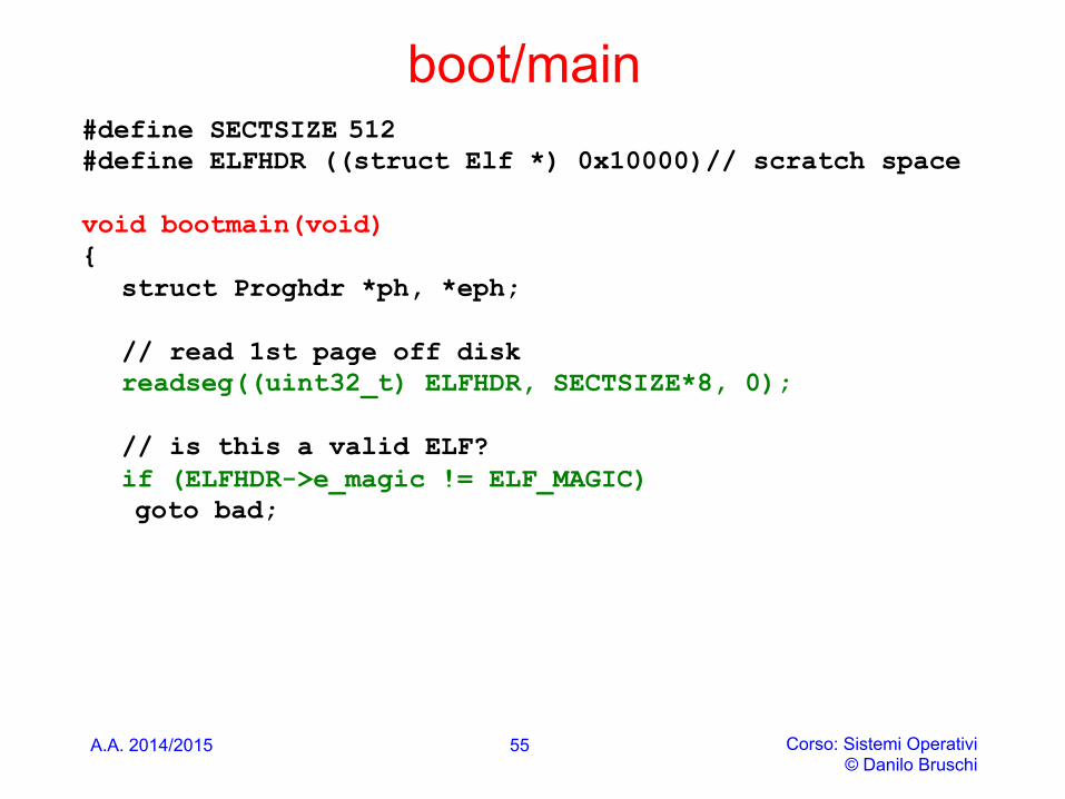
#define SECTSIZE 512 #define ELFHDR ((struct Elf *) 0x10000)// scratch space void bootmain(void) { struct Proghdr *ph, *eph;
// read 1st page off disk readseg((uint32_t) ELFHDR, SECTSIZE*8, 0);
// is this a valid ELF? if (ELFHDR->e_magic != ELF_MAGIC) goto bad;
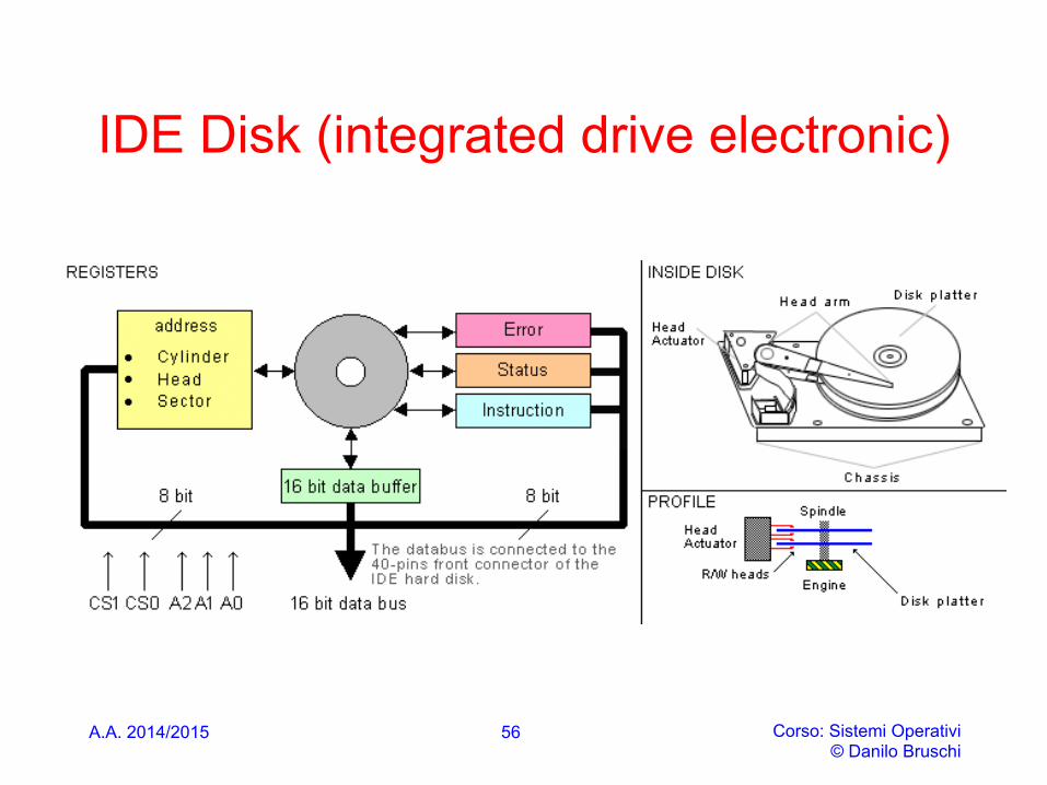
IDE Disk (integrated drive electronic)
A.A. 2014/2015 Corso: Sistemi Operativi © Danilo Bruschi
56
LBA mode
A.A. 2014/2015 Corso: Sistemi Operativi © Danilo Bruschi
57
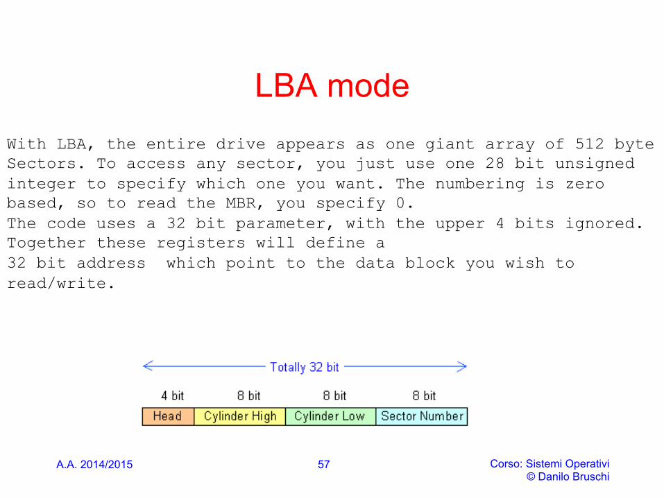
With LBA, the entire drive appears as one giant array of 512 byte Sectors. To access any sector, you just use one 28 bit unsigned integer to specify which one you want. The numbering is zero based, so to read the MBR, you specify 0. The code uses a 32 bit parameter, with the upper 4 bits ignored. Together these registers will define a 32 bit address which point to the data block you wish to read/write.
A.A. 2014/2015 Corso: Sistemi Operativi © Danilo Bruschi
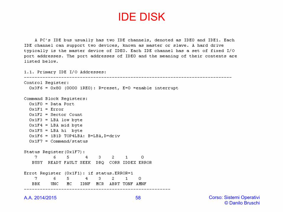
IDE DISK
58
Status Register
A.A. 2014/2015 Corso: Sistemi Operativi © Danilo Bruschi
59
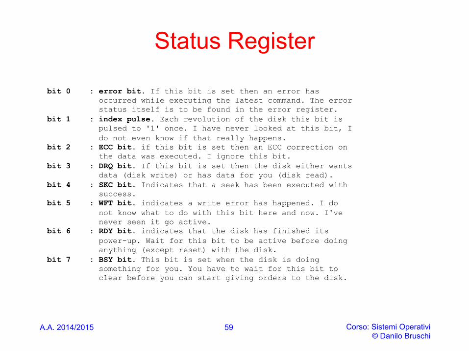
bit 0 : error bit. If this bit is set then an error has occurred while executing the latest command. The error status itself is to be found in the error register. bit 1 : index pulse. Each revolution of the disk this bit is pulsed to '1' once. I have never looked at this bit, I do not even know if that really happens. bit 2 : ECC bit. if this bit is set then an ECC correction on the data was executed. I ignore this bit. bit 3 : DRQ bit. If this bit is set then the disk either wants data (disk write) or has data for you (disk read). bit 4 : SKC bit. Indicates that a seek has been executed with success. bit 5 : WFT bit. indicates a write error has happened. I do not know what to do with this bit here and now. I've never seen it go active. bit 6 : RDY bit. indicates that the disk has finished its power-up. Wait for this bit to be active before doing anything (except reset) with the disk. bit 7 : BSY bit. This bit is set when the disk is doing something for you. You have to wait for this bit to clear before you can start giving orders to the disk.
IDE USAGE
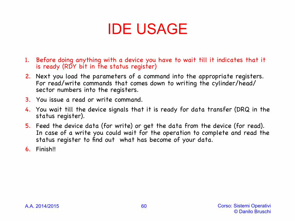
1. Before doing anything with a device you have to wait till it indicates that it is ready (RDY bit in the status register)
2. Next you load the parameters of a command into the appropriate registers. For read/write commands that comes down to writing the cylinder/head/sector numbers into the registers.
3. You issue a read or write command. 4. You wait till the device signals that it is ready for data transfer (DRQ in the
status register). 5. Feed the device data (for write) or get the data from the device (for read).
In case of a write you could wait for the operation to complete and read the status register to find out what has become of your data.
6. Finish!!
A.A. 2014/2015 Corso: Sistemi Operativi © Danilo Bruschi
60
A.A. 2014/2015 Corso: Sistemi Operativi © Danilo Bruschi
61
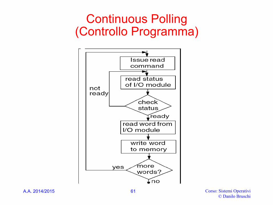
Continuous Polling (Controllo Programma)
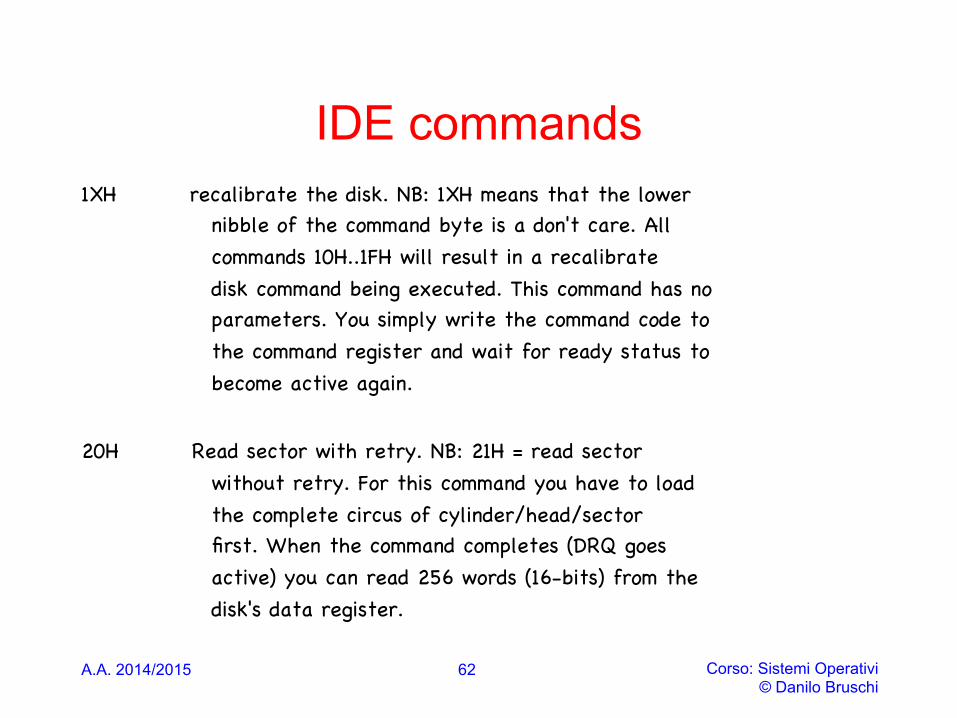
IDE commands 1XH recalibrate the disk. NB: 1XH means that the lower nibble of the command byte is a don't care. All commands 10H..1FH will result in a recalibrate disk command being executed. This command has no parameters. You simply write the command code to the command register and wait for ready status to become active again.
20H Read sector with retry. NB: 21H = read sector without retry. For this command you have to load the complete circus of cylinder/head/sector first. When the command completes (DRQ goes active) you can read 256 words (16-bits) from the disk's data register.
A.A. 2014/2015 Corso: Sistemi Operativi © Danilo Bruschi
62
IDE commands
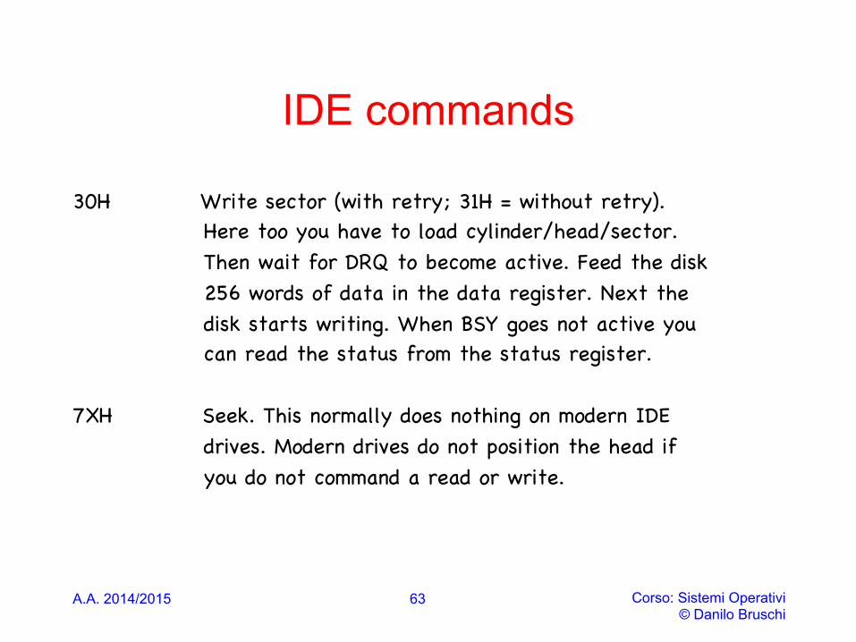
30H Write sector (with retry; 31H = without retry). Here too you have to load cylinder/head/sector. Then wait for DRQ to become active. Feed the disk 256 words of data in the data register. Next the disk starts writing. When BSY goes not active you can read the status from the status register. 7XH Seek. This normally does nothing on modern IDE drives. Modern drives do not position the head if you do not command a read or write.
A.A. 2014/2015 Corso: Sistemi Operativi © Danilo Bruschi
63
A.A. 2014/2015 Corso: Sistemi Operativi © Danilo Bruschi
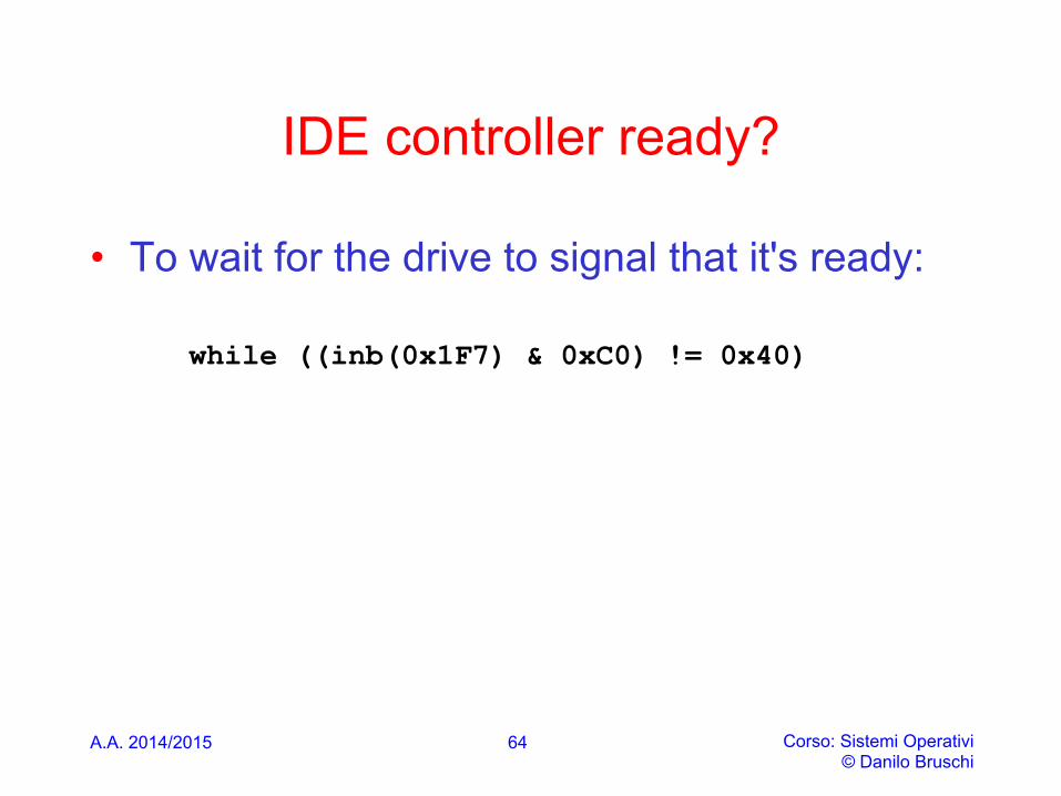
IDE controller ready?
• To wait for the drive to signal that it's ready:
while ((inb(0x1F7) & 0xC0) != 0x40)
64
A.A. 2014/2015 Corso: Sistemi Operativi © Danilo Bruschi
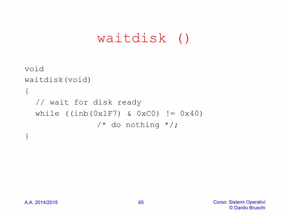
waitdisk ()
void waitdisk(void) { // wait for disk ready while ((inb(0x1F7) & 0xC0) != 0x40) /* do nothing */;
}
65

A.A. 2014/2015 Corso: Sistemi Operativi © Danilo Bruschi
IDE Read Sector
• To read a sector using LBA28: • Send a NULL byte to port 0x1F1: outb(0x1F1, 0x00); • Send a sector count to port 0x1F2: outb(0x1F2, 0x01); • Send the low 8 bits of the block address to port 0x1F3: outb(0x1F3,
(unsigned char)addr); • Send the next 8 bits of the block address to port 0x1F4: outb(0x1F4,
(unsigned char)(addr >> 8); • Send the next 8 bits of the block address to port 0x1F5: outb(0x1F5,
(unsigned char)(addr >> 16); • Send the drive indicator, some magic bits, and highest 4 bits of the block
address to port 0x1F6: outb(0x1F6, (addr >> 24) | 0xE0 )); • Send the command (0x20) to port 0x1F7: outb(0x1F7,0x20);
66
A.A. 2014/2015 Corso: Sistemi Operativi © Danilo Bruschi
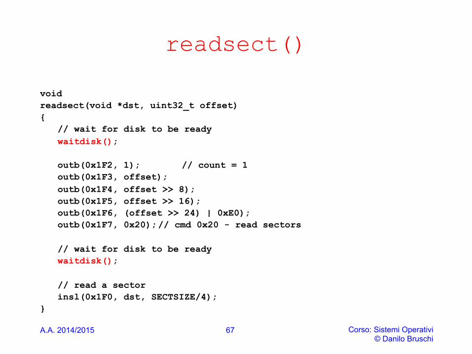
readsect()
void readsect(void *dst, uint32_t offset) {
// wait for disk to be ready waitdisk();
outb(0x1F2, 1); // count = 1 outb(0x1F3, offset); outb(0x1F4, offset >> 8); outb(0x1F5, offset >> 16); outb(0x1F6, (offset >> 24) | 0xE0); outb(0x1F7, 0x20); // cmd 0x20 - read sectors
// wait for disk to be ready waitdisk();
// read a sector insl(0x1F0, dst, SECTSIZE/4);
}
67
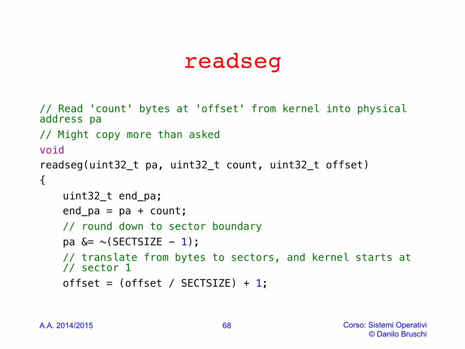
readseg
// Read 'count' bytes at 'offset' from kernel into physical address pa !// Might copy more than asked!void!readseg(uint32_t pa, uint32_t count, uint32_t offset) !{ !
uint32_t end_pa; !end_pa = pa + count; !// round down to sector boundary!pa &= ~(SECTSIZE - 1); !// translate from bytes to sectors, and kernel starts at // sector 1!offset = (offset / SECTSIZE) + 1; !!
A.A. 2014/2015 Corso: Sistemi Operativi
© Danilo Bruschi
68
readseg
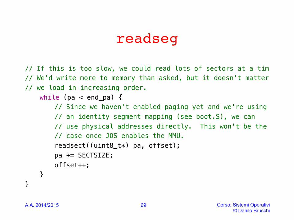
// If this is too slow, we could read lots of sectors at a tim!// We'd write more to memory than asked, but it doesn't matter !// we load in increasing order. !
while (pa < end_pa) { !// Since we haven't enabled paging yet and we're using!// an identity segment mapping (see boot.S), we can!// use physical addresses directly. This won't be the!// case once JOS enables the MMU.!readsect((uint8_t*) pa, offset); !pa += SECTSIZE; !offset++; !
} !} !
A.A. 2014/2015 Corso: Sistemi Operativi © Danilo Bruschi
69

ELF (EXECUTABLE AND LINKABLE FORMAT)
A.A. 2014/2015 Corso: Sistemi Operativi © Danilo Bruschi
70
.elf
• It is a common standard file format for executables, object code, shared libraries, and core dumps
• First published in the System V Application Binary Interface specification,and later in the Tool Interface Standard, it was quickly accepted among different vendors of Unix systems
• In 1999 it was chosen as the standard binary file format for Unix and Unix-like systems on x86 by the 86open project
A.A. 2014/2015 Corso: Sistemi Operativi © Danilo Bruschi
71

A.A. 2014/2015 Corso: Sistemi Operativi © Danilo Bruschi
.elf
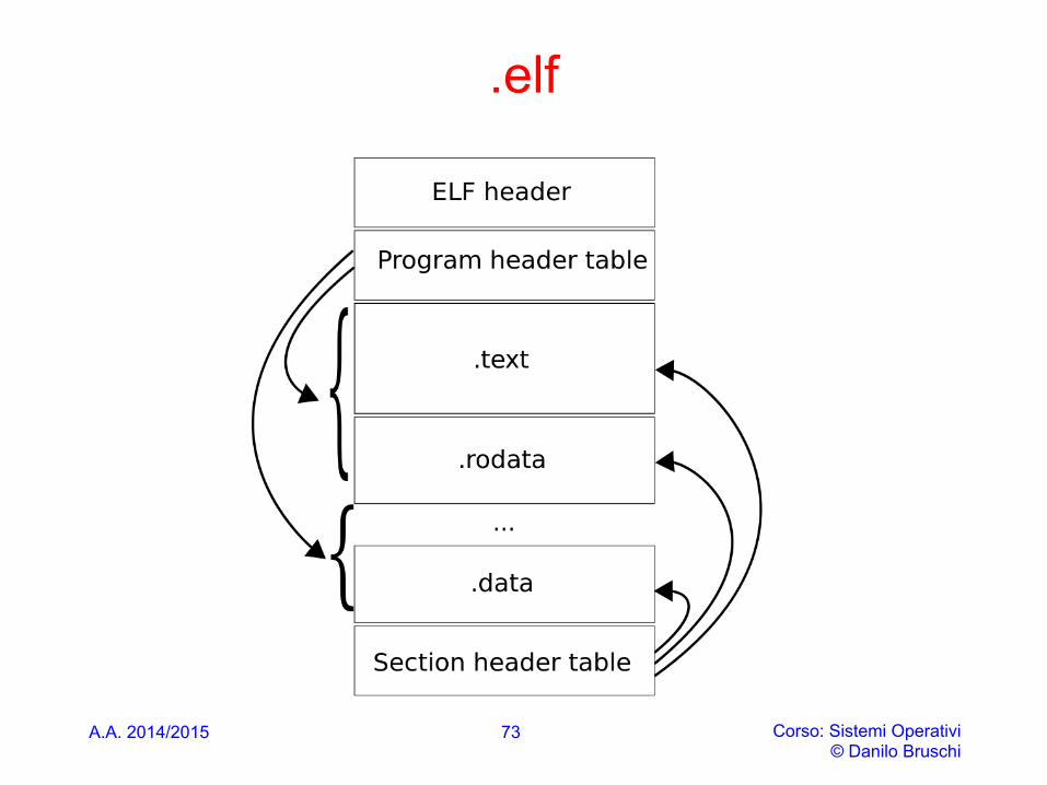
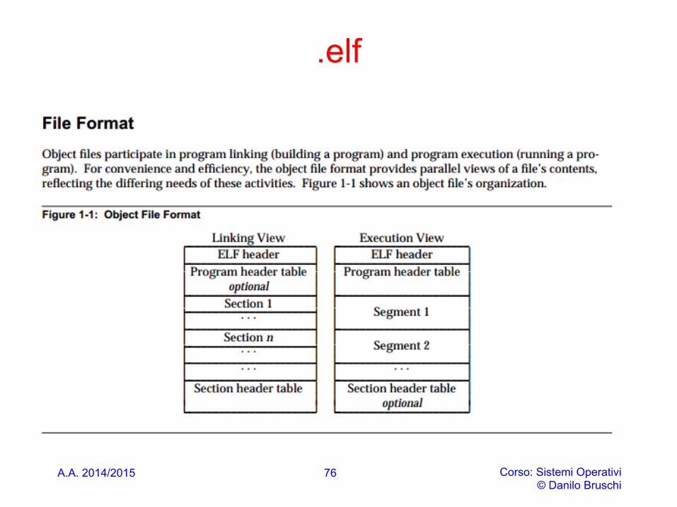
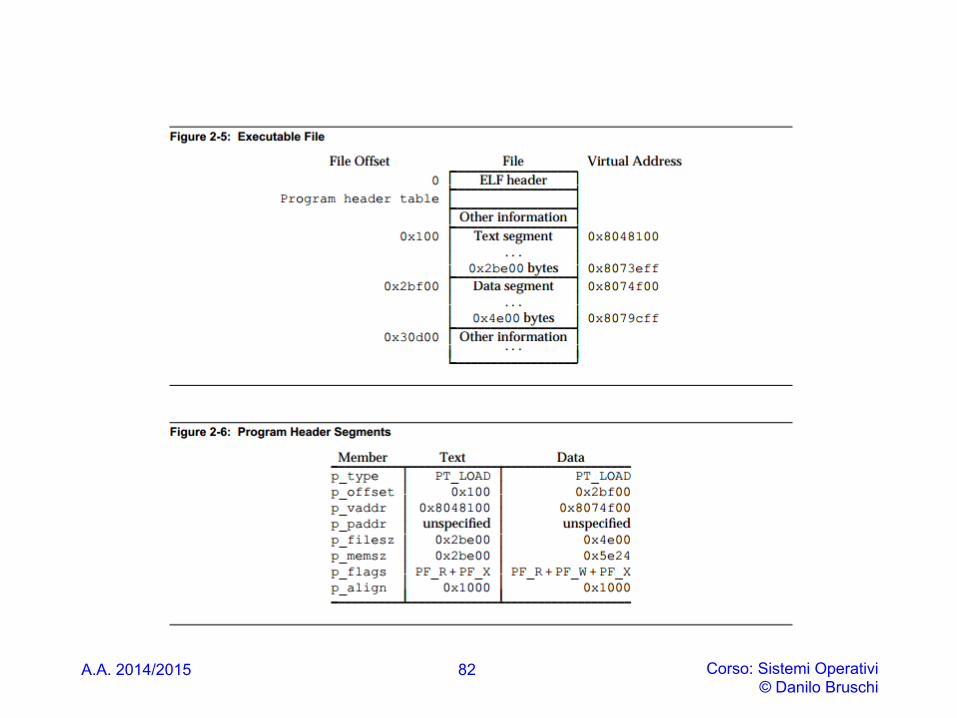
• An ELF binary starts with a fixed-length ELF header, followed by a variable-length program header listing each of the program sections to be loaded
• The ELF format specifies two "views" of an ELF file -- one is used for linking and the other is used for execution. This affords significant flexibility for systems designers
• We talk about sections in object code waiting to be linked into an executable. One or more sections map to a segment in the executable.
72
.elf
A.A. 2014/2015 Corso: Sistemi Operativi © Danilo Bruschi
73
Elf Header
A.A. 2014/2015 Corso: Sistemi Operativi © Danilo Bruschi
74
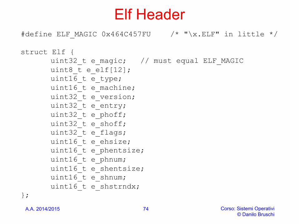
#define ELF_MAGIC 0x464C457FU /* "\x.ELF" in little */ struct Elf {
uint32_t e_magic; // must equal ELF_MAGIC uint8_t e_elf[12]; uint16_t e_type; uint16_t e_machine; uint32_t e_version; uint32_t e_entry; uint32_t e_phoff; uint32_t e_shoff; uint32_t e_flags; uint16_t e_ehsize; uint16_t e_phentsize; uint16_t e_phnum; uint16_t e_shentsize; uint16_t e_shnum; uint16_t e_shstrndx;
};
Header: campi importanti
A.A. 2014/2015 Corso: Sistemi Operativi © Danilo Bruschi
75
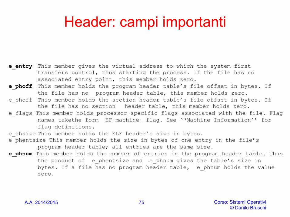
e_entry This member gives the virtual address to which the system first transfers control, thus starting the process. If the file has no associated entry point, this member holds zero.
e_phoff This member holds the program header table’s file offset in bytes. If the file has no program header table, this member holds zero.
e_shoff This member holds the section header table’s file offset in bytes. If the file has no section header table, this member holds zero.
e_flags This member holds processor-specific flags associated with the file. Flag names takethe form EF_machine _flag. See ‘‘Machine Information’’ for flag definitions.
e_ehsize This member holds the ELF header’s size in bytes. e_phentsize This member holds the size in bytes of one entry in the file’s
program header table; all entries are the same size. e_phnum This member holds the number of entries in the program header table. Thus
the product of e_phentsize and e_phnum gives the table’s size in bytes. If a file has no program header table, e_phnum holds the value zero.
A.A. 2014/2015 Corso: Sistemi Operativi © Danilo Bruschi
.elf
76

Program Header
• The ELF header actually points to another group of headers called the program headers
• These headers describe to the operating system anything that might be required for it to load the binary into memory and execute it
• Segments are described by program headers, but so are some other things required to get the executable running
A.A. 2014/2015 Corso: Sistemi Operativi © Danilo Bruschi
77
ELF header and Program header
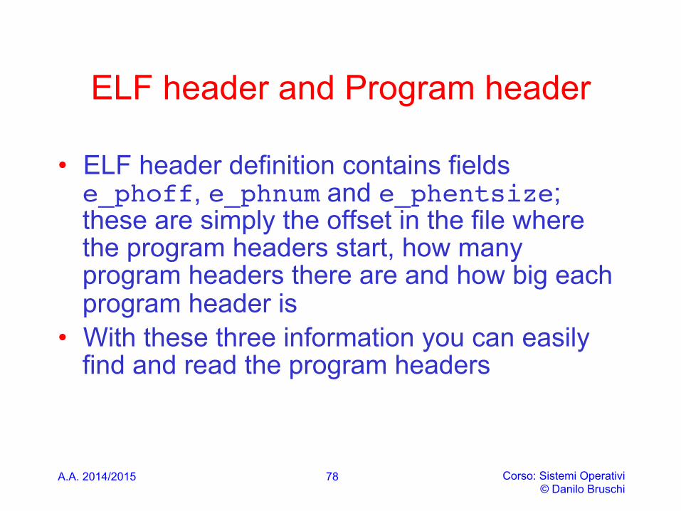
• ELF header definition contains fields e_phoff, e_phnum and e_phentsize; these are simply the offset in the file where the program headers start, how many program headers there are and how big each program header is
• With these three information you can easily find and read the program headers
A.A. 2014/2015 Corso: Sistemi Operativi © Danilo Bruschi
78
Proghdr
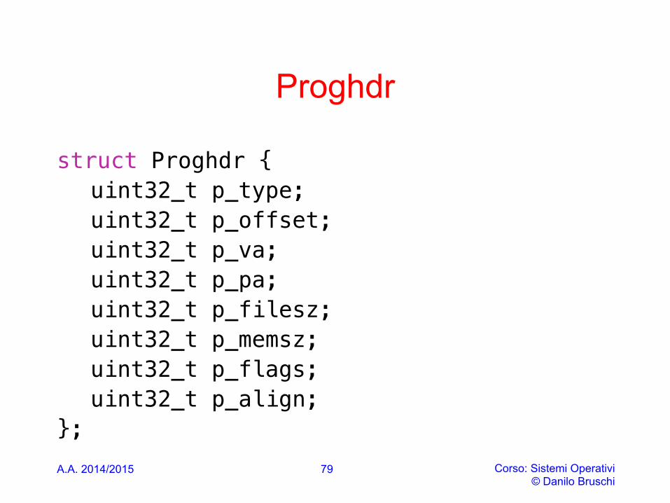
struct Proghdr { !uint32_t p_type; !uint32_t p_offset; !uint32_t p_va; !uint32_t p_pa; !uint32_t p_filesz; !uint32_t p_memsz; !uint32_t p_flags; !uint32_t p_align; !
}; A.A. 2014/2015 Corso: Sistemi Operativi
© Danilo Bruschi
79

Which segments
• The C definitions for these ELF headers are in inc/elf.h. The program segments we're interested in are: • .text: the program's executable instructions • .rodata: read-only data, such as ASCII string constants
produced by the C compiler. (We will not bother setting up the hardware to prohibit writing, however.)
• .data: The data section holds the program's initialized data, such as global variables declared with initializers like int x = 5;.
• .bss
A.A. 2014/2015 Corso: Sistemi Operativi © Danilo Bruschi
80
.elf
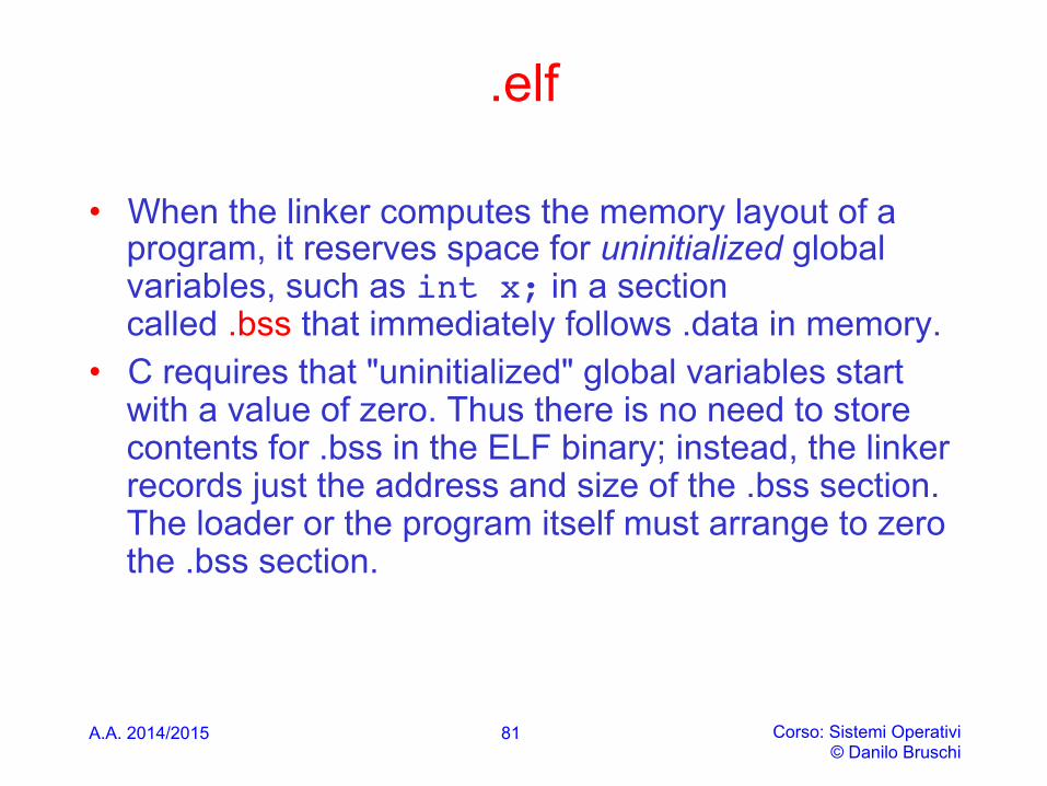
• When the linker computes the memory layout of a program, it reserves space for uninitialized global variables, such as int x; in a section called .bss that immediately follows .data in memory.
• C requires that "uninitialized" global variables start with a value of zero. Thus there is no need to store contents for .bss in the ELF binary; instead, the linker records just the address and size of the .bss section. The loader or the program itself must arrange to zero the .bss section.
A.A. 2014/2015 Corso: Sistemi Operativi © Danilo Bruschi
81
A.A. 2014/2015 Corso: Sistemi Operativi © Danilo Bruschi
82
elf
A.A. 2014/2015 Corso: Sistemi Operativi © Danilo Bruschi
83

.elf
A.A. 2014/2015 Corso: Sistemi Operativi © Danilo Bruschi
84

elf
A.A. 2014/2015 Corso: Sistemi Operativi © Danilo Bruschi
85
elf
A.A. 2014/2015 Corso: Sistemi Operativi © Danilo Bruschi
86
A.A. 2014/2015 Corso: Sistemi Operativi © Danilo Bruschi
Link vs load address
• Take particular note of the "VMA" (or link address) and the "LMA" (or load address) of the .text section. The load address of a section is the memory address at which that section should be loaded into memory.
• In the ELF object, this is stored in the ph->p_pa field (in this case, it really is a physical address, though the ELF specification is vague on the actual meaning of this field).
• The link address of a section is the memory address from which the section expects to execute. The linker encodes the link address in the binary in various ways, such as when the code needs the address of a global variable, with the result that a binary usually won't work if it is executing from an address that it is not linked for
87
A.A. 2014/2015 Corso: Sistemi Operativi © Danilo Bruschi
Kernel LA
• Operating system kernels often like to be linked and run at very high virtual address, such as 0xf0100000, in order to leave the lower part of the processor's virtual address space for user programs to use
• Many machines don't have any physical memory at address 0xf0100000, so we can't count on being able to store the kernel there. Instead, we will use the processor's memory management hardware to map virtual address 0xf0100000 (the link address at which the kernel code expects to run) to physical address 0x00100000 (where the boot loader loaded the kernel into physical memory)
• This way, although the kernel's virtual address is high enough to leave plenty of address space for user processes, it will be loaded in physical memory at the 1MB point in the PC's RAM, just above the BIOS ROM
88
A.A. 2014/2015 Corso: Sistemi Operativi © Danilo Bruschi
boot/main
#include <inc/x86.h> #include <inc/elf.h> /******************************************************************* * This a dirt simple boot loader, whose sole job is to boot * an ELF kernel image from the first IDE hard disk. * * DISK LAYOUT * * This program(boot.S and main.c) is the bootloader. It should * be stored in the first sector of the disk. * * * The 2nd sector onward holds the kernel image. * * * The kernel image must be in ELF format.
89
A.A. 2014/2015 Corso: Sistemi Operativi © Danilo Bruschi
boot/main
* BOOT UP STEPS * * when the CPU boots it loads the BIOS into memory and executes it * * * the BIOS intializes devices, sets of the interrupt routines, and * reads the first sector of the boot device(e.g., hard-drive) * into memory and jumps to it. * * * Assuming this boot loader is stored in the first sector of the * hard-drive, this code takes over... * * * control starts in boot.S -- which sets up protected mode, * and a stack so C code then run, then calls bootmain() * * * bootmain() in this file takes over, reads in the kernel and jumps to it. **********************************************************************/
90
boot/main
A.A. 2014/2015 Corso: Sistemi Operativi © Danilo Bruschi
91
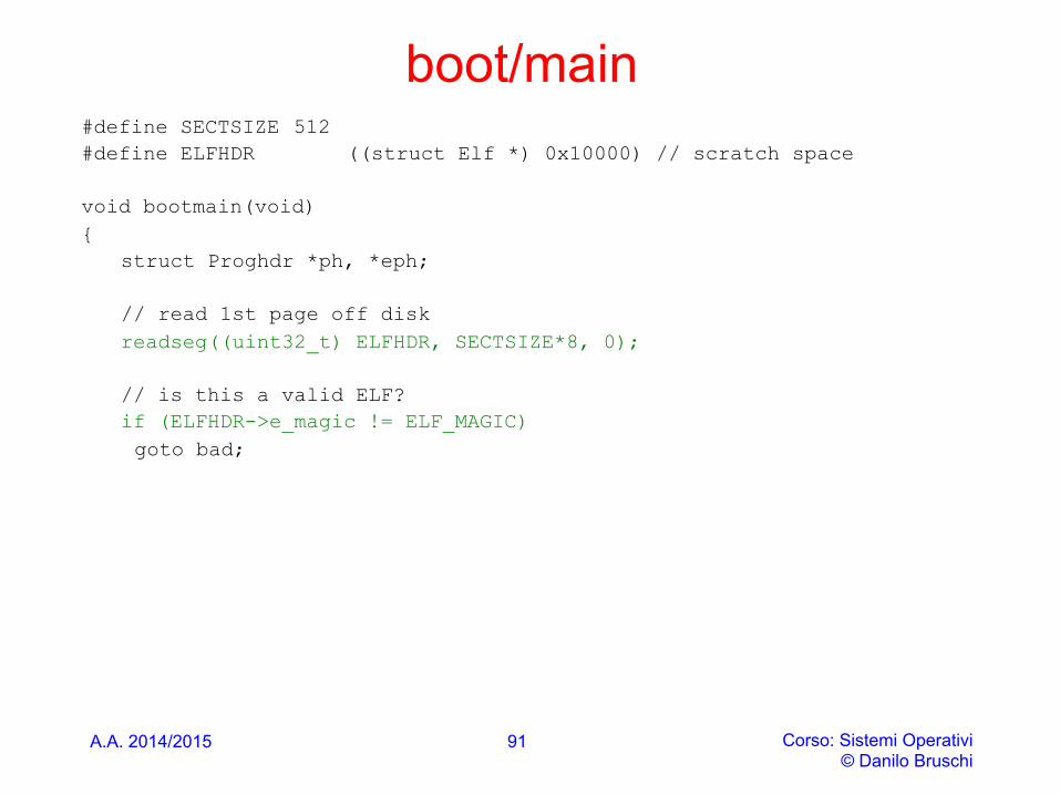
#define SECTSIZE 512 #define ELFHDR ((struct Elf *) 0x10000) // scratch space void bootmain(void) {
struct Proghdr *ph, *eph;
// read 1st page off disk readseg((uint32_t) ELFHDR, SECTSIZE*8, 0);
// is this a valid ELF? if (ELFHDR->e_magic != ELF_MAGIC) goto bad;
A.A. 2014/2015 Corso: Sistemi Operativi © Danilo Bruschi
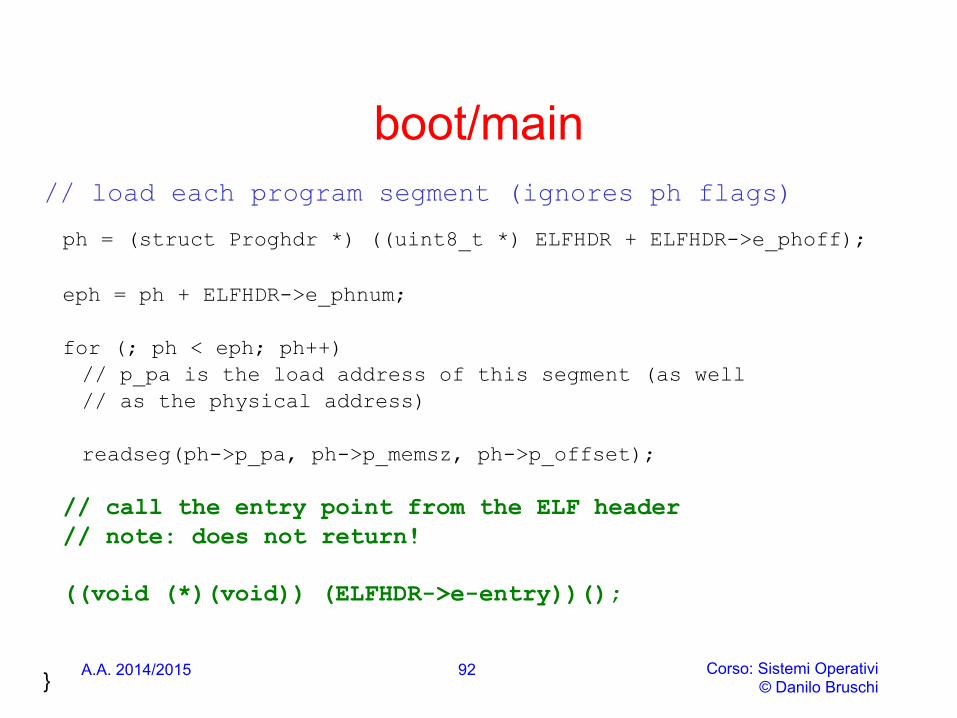
boot/main // load each program segment (ignores ph flags)
ph = (struct Proghdr *) ((uint8_t *) ELFHDR + ELFHDR->e_phoff); eph = ph + ELFHDR->e_phnum; for (; ph < eph; ph++) // p_pa is the load address of this segment (as well // as the physical address) readseg(ph->p_pa, ph->p_memsz, ph->p_offset); // call the entry point from the ELF header // note: does not return! ((void (*)(void)) (ELFHDR->e-entry))();
}
92

A.A. 2014/2015 Corso: Sistemi Operativi © Danilo Bruschi
// Read 'count' bytes at 'offset' from kernel into physical address 'pa'. // Might copy more than asked void readseg(uint32_t pa, uint32_t count, uint32_t offset){ uint32_t end_pa;
end_pa = pa + count;
// round down to sector boundarypa &= ~(SECTSIZE - 1);
// translate from bytes to sectors, and kernel starts at sector 1offset = (offset / SECTSIZE) + 1;
// If this is too slow, we could read lots of sectors at a time.// We'd write more to memory than asked, but it doesn't matter// we load in increasing order.while (pa < end_pa) {// Since we haven't enabled paging yet and we're using// an identity segment mapping (see boot.S), we can// use physical addresses directly. This won't be the// case once JOS enables the MMU.readsect((uint8_t*) pa, offset);pa += SECTSIZE;offset++;
} }
93
A.A. 2014/2015 Corso: Sistemi Operativi © Danilo Bruschi
readsect()
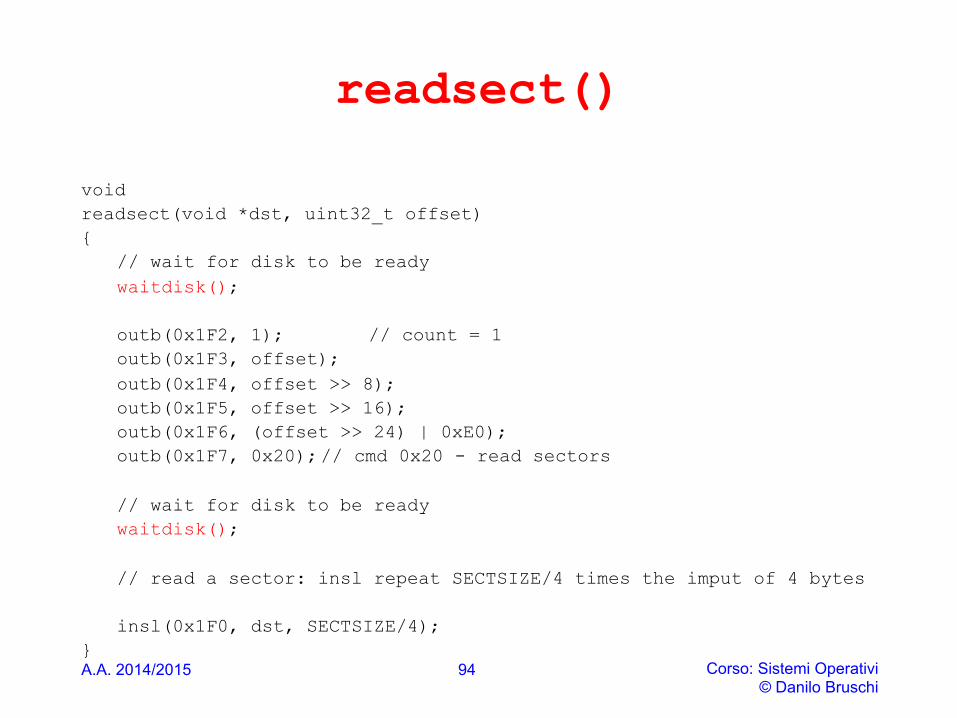
void readsect(void *dst, uint32_t offset) {
// wait for disk to be ready waitdisk();
outb(0x1F2, 1); // count = 1 outb(0x1F3, offset); outb(0x1F4, offset >> 8); outb(0x1F5, offset >> 16); outb(0x1F6, (offset >> 24) | 0xE0); outb(0x1F7, 0x20); // cmd 0x20 - read sectors
// wait for disk to be ready waitdisk();
// read a sector: insl repeat SECTSIZE/4 times the imput of 4 bytes
insl(0x1F0, dst, SECTSIZE/4);
} 94

IL KERNEL
A.A. 2014/2015 Corso: Sistemi Operativi © Danilo Bruschi
95
Kernel
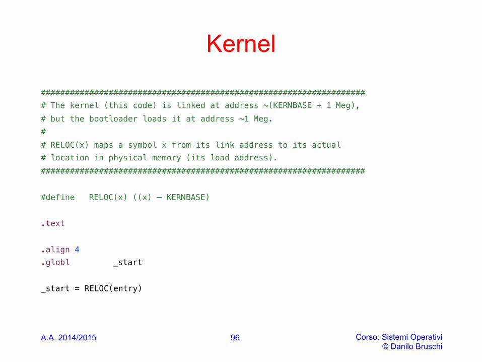
###################################################################!# The kernel (this code) is linked at address ~(KERNBASE + 1 Meg), !# but the bootloader loads it at address ~1 Meg. !# !# RELOC(x) maps a symbol x from its link address to its actual!# location in physical memory (its load address). !###################################################################!!#define RELOC(x) ((x) – KERNBASE)!!.text!!.align 4 !.globl _start !!_start = RELOC(entry)
A.A. 2014/2015 Corso: Sistemi Operativi © Danilo Bruschi
96
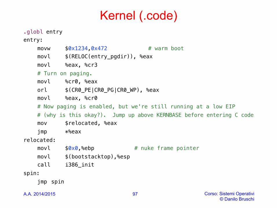
Kernel (.code) .globl entry !entry: !
movw $0x1234,0x472 # warm boot!movl $(RELOC(entry_pgdir)), %eax!movl %eax, %cr3 !# Turn on paging. !movl %cr0, %eax!orl $(CR0_PE|CR0_PG|CR0_WP), %eax!movl %eax, %cr0 !# Now paging is enabled, but we're still running at a low EIP!# (why is this okay?). Jump up above KERNBASE before entering C code!mov $relocated, %eax!jmp *%eax!
relocated: ! movl $0x0,%ebp # nuke frame pointer!
movl $(bootstacktop),%esp!call i386_init !
spin: !jmp spin !
A.A. 2014/2015 Corso: Sistemi Operativi
© Danilo Bruschi
97
Kernel (.data)
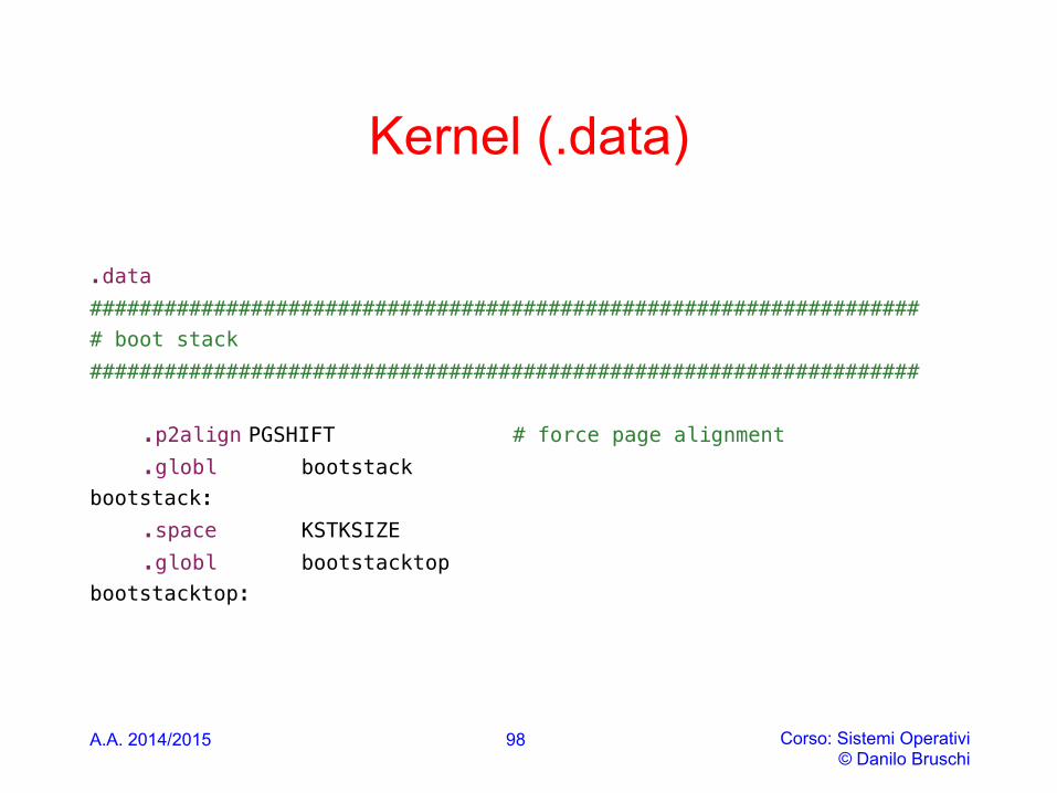
!.data!###################################################################!# boot stack!###################################################################!
!.p2align PGSHIFT # force page alignment!.globl bootstack!
bootstack: !.space KSTKSIZE !.globl bootstacktop !
bootstacktop: !
A.A. 2014/2015 Corso: Sistemi Operativi © Danilo Bruschi
98
A.A. 2014/2015 Corso: Sistemi Operativi © Danilo Bruschi
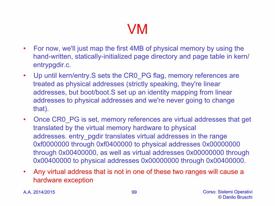
VM • For now, we'll just map the first 4MB of physical memory by using the
hand-written, statically-initialized page directory and page table in kern/entrypgdir.c.
• Up until kern/entry.S sets the CR0_PG flag, memory references are treated as physical addresses (strictly speaking, they're linear addresses, but boot/boot.S set up an identity mapping from linear addresses to physical addresses and we're never going to change that).
• Once CR0_PG is set, memory references are virtual addresses that get translated by the virtual memory hardware to physical addresses. entry_pgdir translates virtual addresses in the range 0xf0000000 through 0xf0400000 to physical addresses 0x00000000 through 0x00400000, as well as virtual addresses 0x00000000 through 0x00400000 to physical addresses 0x00000000 through 0x00400000.
• Any virtual address that is not in one of these two ranges will cause a hardware exception
99

entrypgdir.c
// The entry.S page directory maps the first 4MB of physical memory// starting at virtual address KERNBASE (that is, it maps virtual
// addresses [KERNBASE, KERNBASE+4MB) to physical addresses [0, 4MB)).
// We choose 4MB because that's how much we can map with one page
// table and it's enough to get us through early boot.
// We also map
// virtual addresses [0, 4MB) to physical addresses [0, 4MB); this
// region is critical for a few instructions in entry.S and then we
// never use it again.
A.A. 2014/2015 Corso: Sistemi Operativi © Danilo Bruschi
100
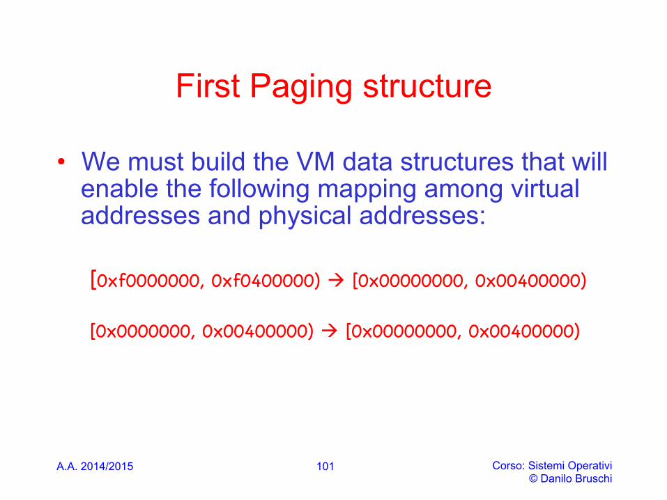
First Paging structure
• We must build the VM data structures that will enable the following mapping among virtual addresses and physical addresses:
[0xf0000000, 0xf0400000) à [0x00000000, 0x00400000) [0x0000000, 0x00400000) à [0x00000000, 0x00400000)
A.A. 2014/2015 Corso: Sistemi Operativi © Danilo Bruschi
101
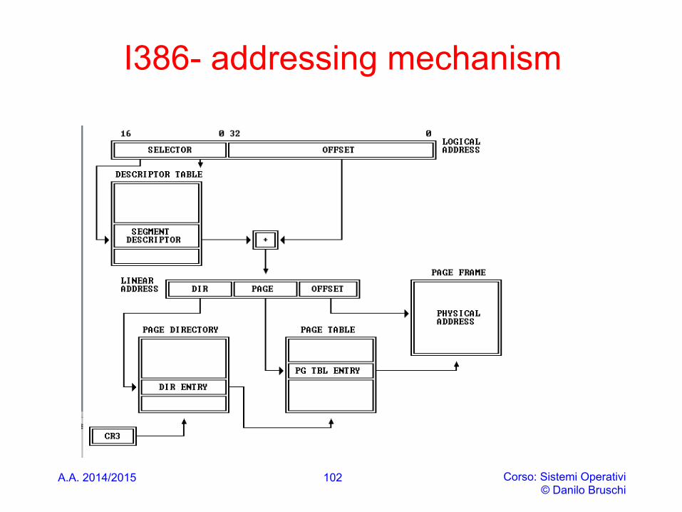
I386- addressing mechanism
A.A. 2014/2015 Corso: Sistemi Operativi © Danilo Bruschi
102
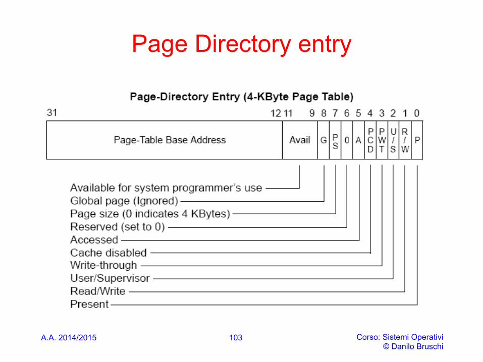
Page Directory entry
A.A. 2014/2015 Corso: Sistemi Operativi © Danilo Bruschi
103
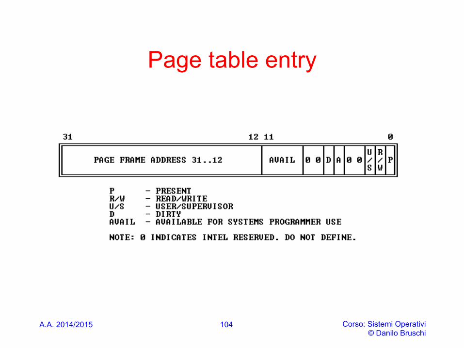
Page table entry
A.A. 2014/2015 Corso: Sistemi Operativi © Danilo Bruschi
104
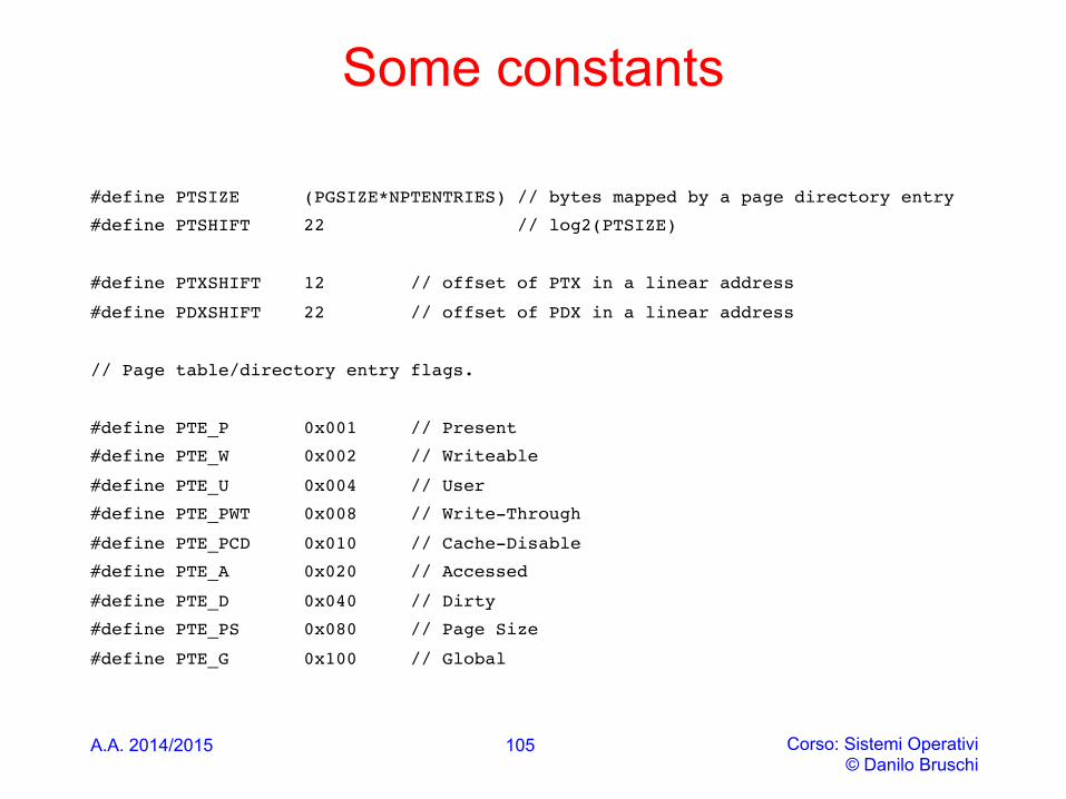
Some constants
#define PTSIZE (PGSIZE*NPTENTRIES) // bytes mapped by a page directory entry
#define PTSHIFT 22 // log2(PTSIZE)
#define PTXSHIFT 12 // offset of PTX in a linear address
#define PDXSHIFT 22 // offset of PDX in a linear address
// Page table/directory entry flags.
#define PTE_P 0x001 // Present
#define PTE_W 0x002 // Writeable
#define PTE_U 0x004 // User
#define PTE_PWT 0x008 // Write-Through
#define PTE_PCD 0x010 // Cache-Disable
#define PTE_A 0x020 // Accessed
#define PTE_D 0x040 // Dirty
#define PTE_PS 0x080 // Page Size
#define PTE_G 0x100 // Global
A.A. 2014/2015 Corso: Sistemi Operativi © Danilo Bruschi
105
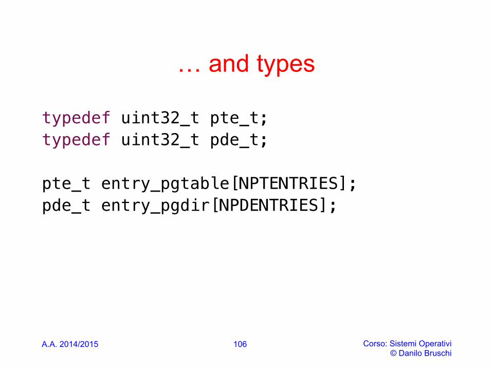
… and types
typedef uint32_t pte_t; !typedef uint32_t pde_t; !!pte_t entry_pgtable[NPTENTRIES]; !pde_t entry_pgdir[NPDENTRIES]; !!
A.A. 2014/2015 Corso: Sistemi Operativi © Danilo Bruschi
106

Page directory
A.A. 2014/2015 Corso: Sistemi Operativi © Danilo Bruschi
107
// Page directories (and page tables), must start on a page boundary, // hence the "__aligned__" attribute. Also, because of restrictions // related to linking and static initializers, we use "x + PTE_P" // here, rather than the more standard "x | PTE_P". Everywhere else // you should use "|" to combine flags. __attribute__((__aligned__(PGSIZE))) pde_t entry_pgdir[NPDENTRIES] = {
// Map VA's [0, 4MB) to PA's [0, 4MB) [0] = ((uintptr_t)entry_pgtable - KERNBASE) + PTE_P,
// Map VA's [KERNBASE, KERNBASE+4MB) to PA's [0, 4MB) [KERNBASE>>PDXSHIFT] = ((uintptr_t)entry_pgtable - KERNBASE) + PTE_P + PTE_W
};
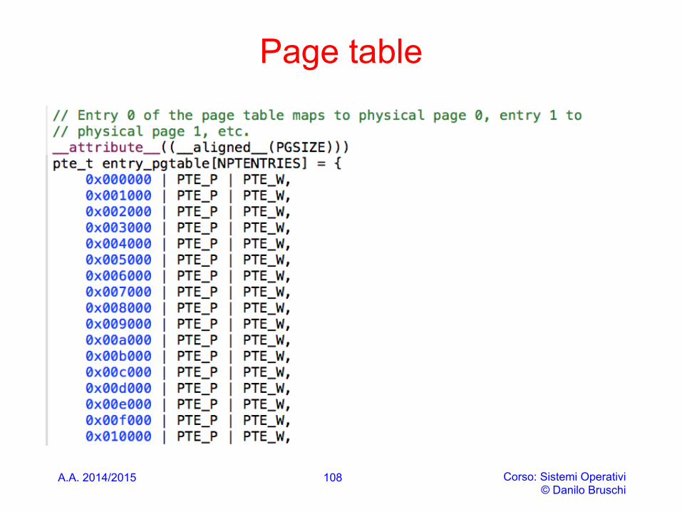
Page table
A.A. 2014/2015 Corso: Sistemi Operativi © Danilo Bruschi
108
A.A. 2014/2015 Corso: Sistemi Operativi © Danilo Bruschi
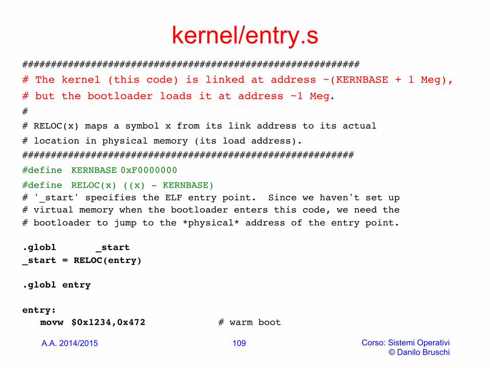
kernel/entry.s ###########################################################
# The kernel (this code) is linked at address ~(KERNBASE + 1 Meg),
# but the bootloader loads it at address ~1 Meg.#
# RELOC(x) maps a symbol x from its link address to its actual
# location in physical memory (its load address).
##########################################################
#define KERNBASE 0xF0000000
#define RELOC(x) ((x) - KERNBASE)# '_start' specifies the ELF entry point. Since we haven't set up# virtual memory when the bootloader enters this code, we need the# bootloader to jump to the *physical* address of the entry point.
.globl _start_start = RELOC(entry)
.globl entry
entry:movw $0x1234,0x472 # warm boot
109
A.A. 2014/2015 Corso: Sistemi Operativi © Danilo Bruschi
110
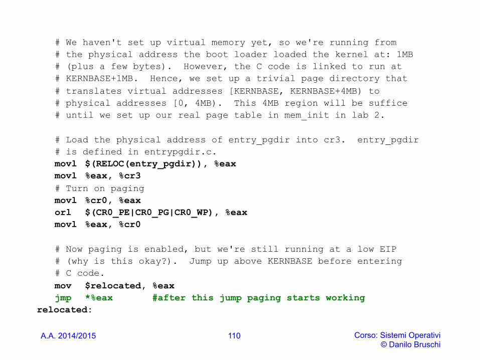
# We haven't set up virtual memory yet, so we're running from # the physical address the boot loader loaded the kernel at: 1MB # (plus a few bytes). However, the C code is linked to run at # KERNBASE+1MB. Hence, we set up a trivial page directory that # translates virtual addresses [KERNBASE, KERNBASE+4MB) to # physical addresses [0, 4MB). This 4MB region will be suffice # until we set up our real page table in mem_init in lab 2.
# Load the physical address of entry_pgdir into cr3. entry_pgdir # is defined in entrypgdir.c. movl $(RELOC(entry_pgdir)), %eax movl %eax, %cr3 # Turn on paging movl %cr0, %eax orl $(CR0_PE|CR0_PG|CR0_WP), %eax movl %eax, %cr0
# Now paging is enabled, but we're still running at a low EIP # (why is this okay?). Jump up above KERNBASE before entering # C code. mov $relocated, %eax jmp *%eax #after this jump paging starts working
relocated:
A.A. 2014/2015 Corso: Sistemi Operativi © Danilo Bruschi
kern/entry.s
• The processor is still executing instructions at low addresses after paging is enabled, which works since entrypgdir maps low addresses. If we had omitted entry 0 from entrypgdir, the computer would have crashed when trying to execute the instruction after the one that enabled paging
• The indirect jump is needed because the assembler would generate a PC-relative direct jump, which would execute the low-memory version of kernel
111
A.A. 2014/2015 Corso: Sistemi Operativi © Danilo Bruschi
kern/entry.s
• Now entry needs to transfer to the kernel’s C code, and run it in high memory.
• First it must make the stack pointer, %esp, point to a stack so that C code will work. All symbols have high addresses, including stack, so the stack will still be valid even when the low mappings are removed. Finally entry jumps to kernel, which is also a high address
• entry cannot return, since there’s no return PC on the stack
112
A.A. 2014/2015 Corso: Sistemi Operativi © Danilo Bruschi
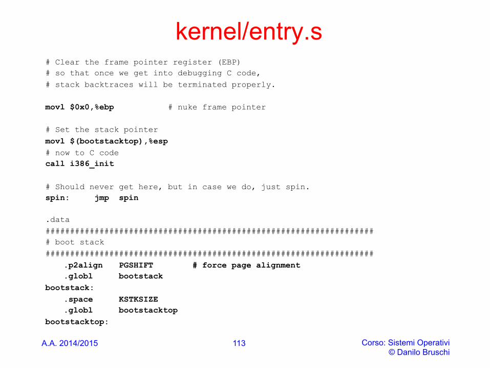
kernel/entry.s # Clear the frame pointer register (EBP) # so that once we get into debugging C code, # stack backtraces will be terminated properly. movl $0x0,%ebp # nuke frame pointer # Set the stack pointer movl $(bootstacktop),%esp # now to C code call i386_init # Should never get here, but in case we do, just spin. spin: jmp spin
.data ################################################################### # boot stack ###################################################################
.p2align PGSHIFT # force page alignment .globl bootstack
bootstack: .space KSTKSIZE .globl bootstacktop
bootstacktop:
113
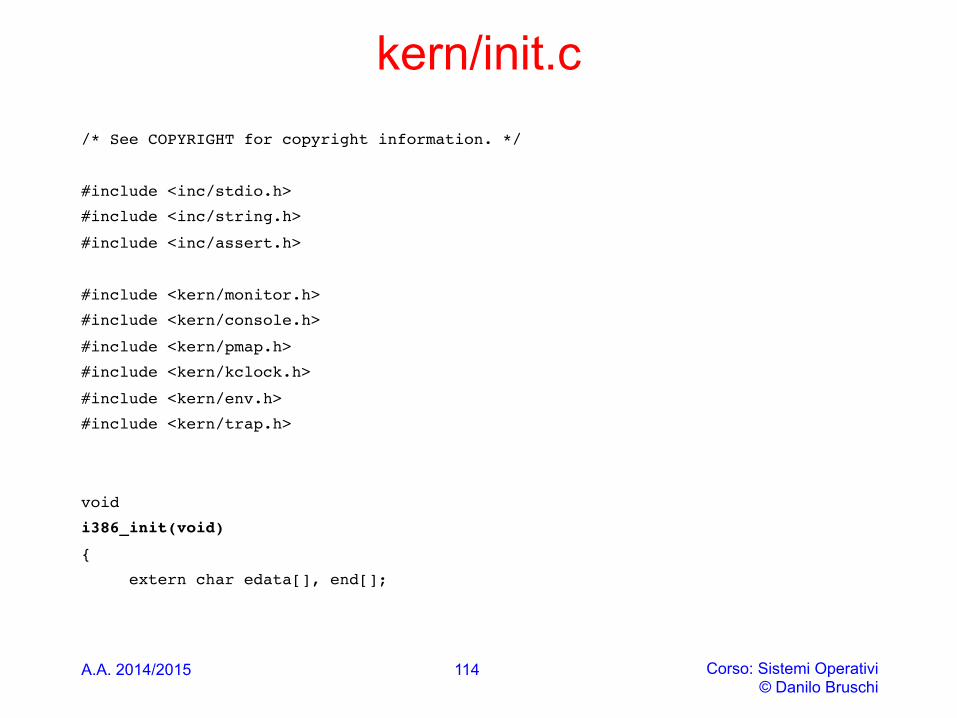
kern/init.c /* See COPYRIGHT for copyright information. */
#include <inc/stdio.h>
#include <inc/string.h>
#include <inc/assert.h>
#include <kern/monitor.h>
#include <kern/console.h>
#include <kern/pmap.h>
#include <kern/kclock.h>
#include <kern/env.h>
#include <kern/trap.h>
void
i386_init(void)
{
extern char edata[], end[];
A.A. 2014/2015 Corso: Sistemi Operativi © Danilo Bruschi
114
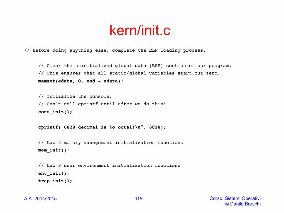
kern/init.c // Before doing anything else, complete the ELF loading process.
// Clear the uninitialized global data (BSS) section of our program.
// This ensures that all static/global variables start out zero.
memset(edata, 0, end - edata);
// Initialize the console.
// Can't call cprintf until after we do this!
cons_init();
cprintf("6828 decimal is %o octal!\n", 6828);
// Lab 2 memory management initialization functions
mem_init();
// Lab 3 user environment initialization functions
env_init();
trap_init();
A.A. 2014/2015 Corso: Sistemi Operativi © Danilo Bruschi
115