LBT80164-B HPA700 I-F-UK-D - segshop.it · NOTA: se viene scelta l'opzione dei 5 allarmi nell'arco...
44
DS80HP84-001B LBT80164 Manuale di installazione Notice d'installation Installation Manual Installation Handbuch Sirena da esterno Sirène extérieure Outdoor Siren Aussensirene I F GB D HPA701 HPA702L HPA702LG (INCERT N° B-767-0005) HPA703XP (INCERT N° B-767-0005) HPA703XP/H
Transcript of LBT80164-B HPA700 I-F-UK-D - segshop.it · NOTA: se viene scelta l'opzione dei 5 allarmi nell'arco...

1/44 HPA701 - HPA702L - HPA702LG - HPA703XP - HPA703XP
DS80HP84-001B LBT80164
Man
uale
di i
nsta
llazi
one
Not
ice
d'in
stal
latio
n In
stal
latio
n M
anua
l In
stal
latio
n H
andb
uch
Sirena da esterno Sirène extérieure Outdoor Siren Aussensirene
I F GB D
HPA701
HPA702L
HPA702LG (INCERT N° B-767-0005)
HPA703XP (INCERT N° B-767-0005)
HPA703XP/H
2/44 HPA700
SOMMARIO
SOMMARIO .........................................................................................................................................................2 1.0 CARATTERISTICHE GENERALI...................................................................................................................2
1.1 GESTIONE ALLARMI ................................................................................................................................3 1.2 AUTODIAGNOSTICA.................................................................................................................................3
2.0 INSTALLAZIONE ...........................................................................................................................................4 3.0 MODULO SIRENA .........................................................................................................................................5
3.1 PROGRAMMAZIONI DI FABBRICA ..........................................................................................................6 3.2 PROGRAMMAZIONE MODALITA’ DI SUONATA .....................................................................................6 3.3 PROGRAMMAZIONI TIME OUT SUONATA .............................................................................................7 3.4 PROGRAMMAZIONI TIPO INGRESSI ......................................................................................................7 3.5 PROGRAMMAZIONI RIFERIMENTO INGRESSI......................................................................................7 3.6 PROGRAMMAZIONI CONTEGGIO ALLARMI ..........................................................................................7 3.7 PROGRAMMAZIONI FUNZIONE PONTEGGI ..........................................................................................7
4.0 MODULO LAMPEGGIATORE .......................................................................................................................8 5.0 MODULO PROTEZIONI ................................................................................................................................8 6.0 ESEMPIO DI COLLEGAMENTO .................................................................................................................10 7.0 CARATTERISTICHE TECNICHE ................................................................................................................11
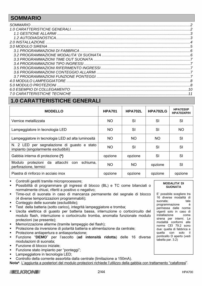
1.0 CARATTERISTICHE GENERALI
MODELLO HPA701 HPA702L HPA702LG HPA703XP HPA703XP/H
Vernice metallizzata NO SI SI SI
Lampeggiatore in tecnologia LED NO SI SI NO
Lampeggiatore in tecnologia LED ad alta luminosità NO NO NO SI
N. 2 LED per segnalazione di guasto e stato impianto (singolarmente escludibili) NO SI SI SI
Gabbia interna di protezione (*) opzione opzione SI SI
Modulo protezioni da attacchi con schiuma, perforazione, termici NO NO opzione SI
Piastra di rinforzo in acciaio inox opzione opzione opzione opzione
Controlli gestiti tramite microprocessore; Possibilità di programmare gli ingressi di blocco (BL) e TC come bilanciati o
normalmente chiusi, riferiti a positivo o negativo; Time-out di suonata in caso di mancanza permanente del segnale di blocco
(4 diverse temporizzazioni programmabili); Conteggio delle suonate (escludibile); Test della batteria (sotto carico), integrità lampeggiatore e tromba; Uscita elettrica di guasto per batteria bassa, interruzione o cortocircuito del
modulo flash, interruzione o cortocircuito tromba, anomalia funzionale modulo protezioni (se presente);
Memorizzazione allarme (tramite lampeggio del flash); Protezione da inversione di polarità batteria e alimentazione da centrale; Protezione antiapertura e antiasportazione; Funzione “DEMO” per l’ascolto (ad intensità ridotta) delle 16 diverse
modulazioni di suonata; Funzione di blocco iniziale; Funzione stato impianto per “ponteggi”; Lampeggiatore in tecnologia LED; Controllo della corrente assorbita dalla centrale (limitazione a 150mA).
Nota*. L’aggiunta a posteriori del modulo protezioni richiede l’utilizzo della gabbia con trattamento “cataforesi”.
MODALITA’ DI SUONATA
E’ possibile scegliere tra 16 diverse modalità di suonata; tale programmazione è permessa dalle norme vigenti solo in caso di installazione come sirena per interni. Le modalità conformi alle norme CEI 79.2 sono due: quella di fabbrica e quella con solo il ponticello D aperto (vedi tabella par. 3.2)
3/44 HPA700
1.1 GESTIONE ALLARMI Dopo aver correttamente cablato e richiuso entrambi gli ingressi (funzione di blocco al power-on), la sirena genera allarme soltanto quando vengono a mancare sia il segnale di stato impianto “TC” (segnale presente = impianto disattivato) che il segnale di blocco allarme “BL”. L’assenza di uno solo dei due non provoca nessun evento di allarme; per bloccare un allarme in corso, è sufficiente fornire il segnale di blocco. Nel caso il segnale di blocco permanga aperto a lungo, interviene il timeout programmato tramite gli appositi ponticelli che provvede a far cessare la suonata. Bloccato l’allarme, il flash continua a lampeggiare (ogni 2,5 s circa). La sirena permane in tale stato di memorizzazione allarme finché non viene fornito il segnale TC (si spegne l’impianto). NOTA: In caso di batteria scarica (al di sotto della soglia di 11,2V), viene interrotto il lampeggio del flash per preservare la restante energia a favore dell’allarme acustico. A completare le prestazioni della sirena sono disponibili, tramite appositi ponticelli, due funzioni aggiuntive: Conteggio allarmi e Funzione Ponteggi (Per dettagli sul funzionamento vedere i paragrafi 3.6 e 3.7). Nel caso la centrale non disponga di una uscita di stato impianto è necessario collegare insieme i due segnali di BL e TC, tenendo presente che in tal modo si vengono a perdere parte delle prestazioni offerte (memoria allarme, conteggio allarmi, funzione ponteggi). NOTA: E’ indispensabile la connessione della batteria tampone in quanto, essendo limitato l’assorbimento di corrente dalla centrale, senza di essa la sirena non è in grado di suonare.
1.2 AUTODIAGNOSTICA Le sirene della famiglia HPA700 implementano una innovativa funzione di “autodiagnosi attiva” che provvede a verificare l’integrità della batteria, della tromba, del lampeggiatore e del modulo protezioni (se presente). Questo test viene effettuato ad ogni attivazione impianto (apertura dell’ingresso TC) e dura 2 secondi; in questo intervallo di tempo vengono sollecitati la tromba ed il flash e viene effettuata una misura sotto carico della tensione di batteria, fornendo quindi eventuali segnalazioni di anomalia tramite l’uscita “guasto”. In questo modo si ha sempre un controllo della piena funzionalità della sirena ad ogni attivazione dell’impianto. Un test analogo viene anche effettuato ad ogni inizio e fine allarme; a differenza del precedente, questo è istantaneo in quanto la batteria è già sotto carico. La segnalazione di anomalia viene quindi aggiornata solo in queste tre condizioni. Eventuali guasti sono anche segnalati tramite il LED giallo locale (presente sul modulo lampeggiatore), che però è visibile solo ad impianto disattivo (viene abilitata l’accensione solo con TC presente visualizzando solo la prima anomalia riscontrata in ordine cronologico). NOTA: Qualora si utilizzi un unico comando per BL e TC la suonata viene ritardata di 2 secondi.
4/44 HPA700
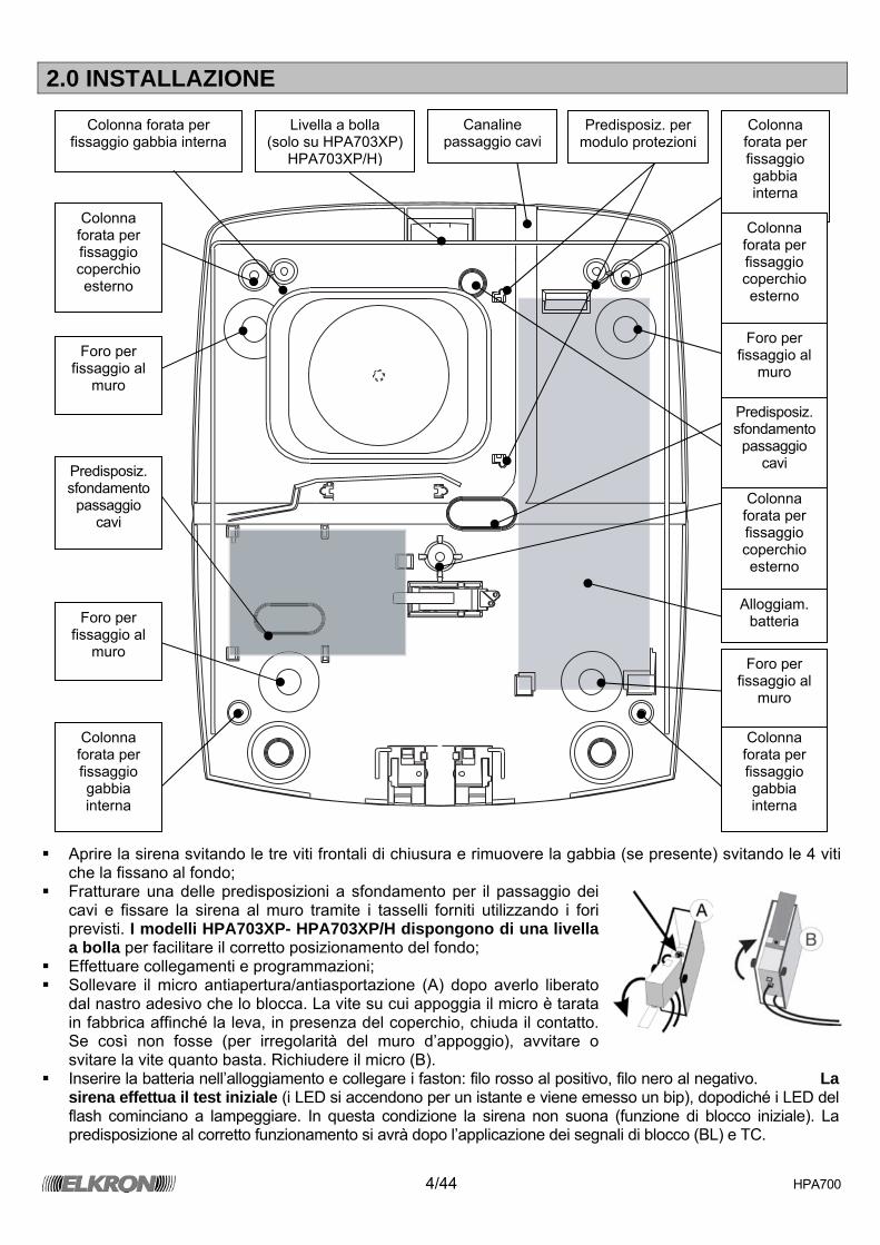
2.0 INSTALLAZIONE
Aprire la sirena svitando le tre viti frontali di chiusura e rimuovere la gabbia (se presente) svitando le 4 viti
che la fissano al fondo; Fratturare una delle predisposizioni a sfondamento per il passaggio dei
cavi e fissare la sirena al muro tramite i tasselli forniti utilizzando i fori previsti. I modelli HPA703XP- HPA703XP/H dispongono di una livella a bolla per facilitare il corretto posizionamento del fondo;
Effettuare collegamenti e programmazioni; Sollevare il micro antiapertura/antiasportazione (A) dopo averlo liberato
dal nastro adesivo che lo blocca. La vite su cui appoggia il micro è tarata in fabbrica affinché la leva, in presenza del coperchio, chiuda il contatto. Se così non fosse (per irregolarità del muro d’appoggio), avvitare o svitare la vite quanto basta. Richiudere il micro (B).
Inserire la batteria nell’alloggiamento e collegare i faston: filo rosso al positivo, filo nero al negativo. La sirena effettua il test iniziale (i LED si accendono per un istante e viene emesso un bip), dopodiché i LED del flash cominciano a lampeggiare. In questa condizione la sirena non suona (funzione di blocco iniziale). La predisposizione al corretto funzionamento si avrà dopo l’applicazione dei segnali di blocco (BL) e TC.
Canaline passaggio cavi
Colonna forata per fissaggio gabbia interna
Colonna forata per fissaggio gabbia interna
Colonna forata per fissaggio coperchio esterno
Colonna forata per fissaggio coperchio esterno
Colonna forata per fissaggio coperchio esterno
Colonna forata per fissaggio gabbia interna
Colonna forata per fissaggio gabbia interna
Livella a bolla (solo su HPA703XP)
HPA703XP/H)
Foro per fissaggio al
muro
Foro per fissaggio al
muro
Foro per fissaggio al
muro Foro per
fissaggio al muro
Predisposiz. sfondamento
passaggio cavi
Predisposiz. sfondamento
passaggio cavi
Alloggiam. batteria
Predisposiz. per modulo protezioni
5/44 HPA700
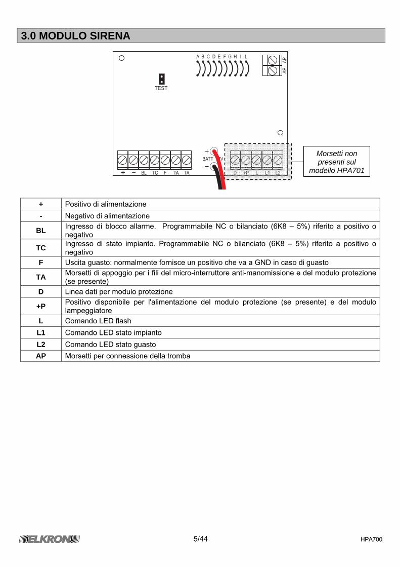
3.0 MODULO SIRENA
A
AP
AP
TEST
B C D E F G H I L
BATT 12V
+ - BL TC F TA TA D +P L L1 L2
+ Positivo di alimentazione - Negativo di alimentazione
BL Ingresso di blocco allarme. Programmabile NC o bilanciato (6K8 – 5%) riferito a positivo o negativo
TC Ingresso di stato impianto. Programmabile NC o bilanciato (6K8 – 5%) riferito a positivo o negativo
F Uscita guasto: normalmente fornisce un positivo che va a GND in caso di guasto
TA Morsetti di appoggio per i fili del micro-interruttore anti-manomissione e del modulo protezione (se presente)
D Linea dati per modulo protezione
+P Positivo disponibile per l'alimentazione del modulo protezione (se presente) e del modulo lampeggiatore
L Comando LED flash L1 Comando LED stato impianto L2 Comando LED stato guasto AP Morsetti per connessione della tromba
Morsetti non presenti sul
modello HPA701
6/44 HPA700
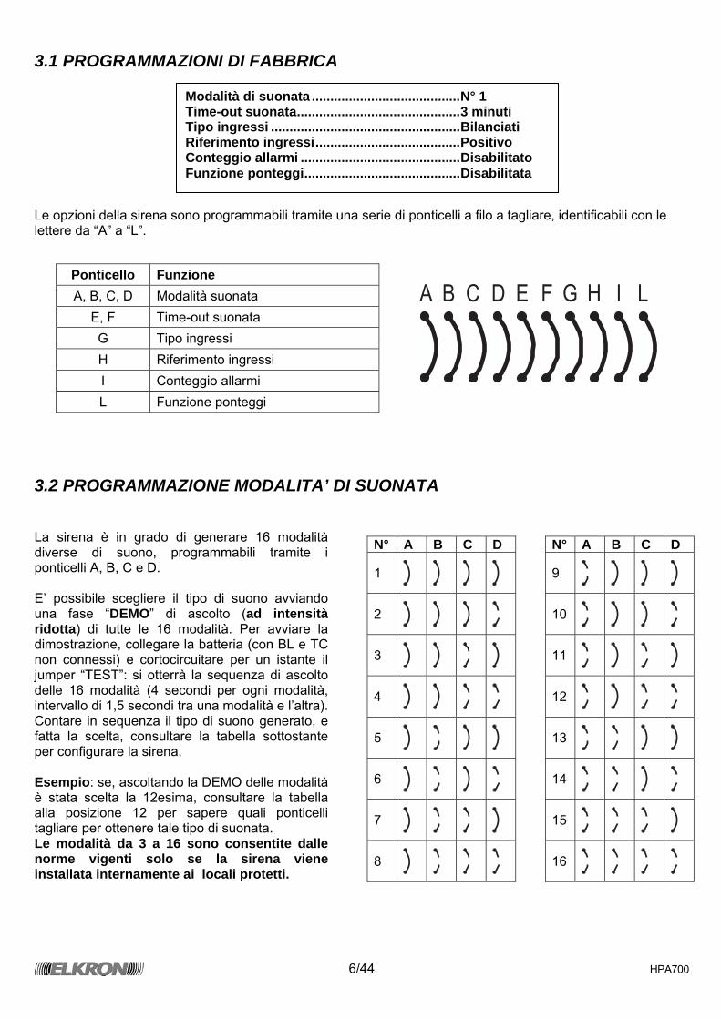
3.1 PROGRAMMAZIONI DI FABBRICA Le opzioni della sirena sono programmabili tramite una serie di ponticelli a filo a tagliare, identificabili con le lettere da “A” a “L”.
A B C D E F G H I L
3.2 PROGRAMMAZIONE MODALITA’ DI SUONATA La sirena è in grado di generare 16 modalità diverse di suono, programmabili tramite i ponticelli A, B, C e D. E’ possibile scegliere il tipo di suono avviando una fase “DEMO” di ascolto (ad intensità ridotta) di tutte le 16 modalità. Per avviare la dimostrazione, collegare la batteria (con BL e TC non connessi) e cortocircuitare per un istante il jumper “TEST”: si otterrà la sequenza di ascolto delle 16 modalità (4 secondi per ogni modalità, intervallo di 1,5 secondi tra una modalità e l’altra). Contare in sequenza il tipo di suono generato, e fatta la scelta, consultare la tabella sottostante per configurare la sirena. Esempio: se, ascoltando la DEMO delle modalità è stata scelta la 12esima, consultare la tabella alla posizione 12 per sapere quali ponticelli tagliare per ottenere tale tipo di suonata. Le modalità da 3 a 16 sono consentite dalle norme vigenti solo se la sirena viene installata internamente ai locali protetti.
Ponticello Funzione A, B, C, D Modalità suonata
E, F Time-out suonata G Tipo ingressi H Riferimento ingressi I Conteggio allarmi L Funzione ponteggi
N° A B C D N° A B C D
1
9
2
10
3
11
4
12
5
13
6
14
7
15
8
16
Modalità di suonata ........................................N° 1 Time-out suonata............................................3 minuti Tipo ingressi ...................................................Bilanciati Riferimento ingressi.......................................Positivo Conteggio allarmi ...........................................Disabilitato Funzione ponteggi..........................................Disabilitata
7/44 HPA700
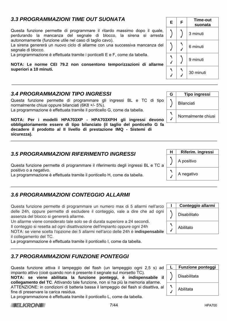
3.3 PROGRAMMAZIONI TIME OUT SUONATA Questa funzione permette di programmare il ritardo massimo dopo il quale, perdurando la mancanza del segnale di blocco, la sirena si arresta autonomamente (funzione utile nel caso di taglio cavo). La sirena genererà un nuovo ciclo di allarme con una successiva mancanza del segnale di blocco. La programmazione è effettuata tramite i ponticelli E e F, come da tabella. NOTA: Le norme CEI 79.2 non consentono temporizzazioni di allarme superiori a 10 minuti.
3.4 PROGRAMMAZIONI TIPO INGRESSI Questa funzione permette di programmare gli ingressi BL e TC di tipo normalmente chiusi oppure bilanciati (6K8 +/- 5%). La programmazione è effettuata tramite il ponticello G, come da tabella. NOTA: Per i modelli HPA703XP - HPA703XP/H gli ingressi devono obbligatoriamente essere di tipo bilanciato (il taglio del ponticello G fa decadere il prodotto al II livello di prestazione IMQ - Sistemi di sicurezza).
3.5 PROGRAMMAZIONI RIFERIMENTO INGRESSI Questa funzione permette di programmare il riferimento degli ingressi BL e TC a positivo o a negativo. La programmazione è effettuata tramite il ponticello H, come da tabella.
3.6 PROGRAMMAZIONI CONTEGGIO ALLARMI Questa funzione permette di programmare un numero max di 5 allarmi nell'arco
delle 24h, oppure permette di escludere il conteggio, vale a dire che ad ogni
assenza del blocco si genererà allarme.
Un allarme viene considerato tale solo se di durata superiore a 24 secondi.
Il conteggio si resetta ad ogni disattivazione dell'impianto oppure ogni 24h
NOTA: se viene scelta l'opzione dei 5 allarmi nell'arco delle 24h è indispensabile il collegamento del TC.
La programmazione è effettuata tramite il ponticello I, come da tabella.
3.7 PROGRAMMAZIONI FUNZIONE PONTEGGI Questa funzione attiva il lampeggio del flash (un lampeggio ogni 2,5 s) ad impianto attivo (cioè quando non è presente il segnale sul morsetto TC). NOTA: se viene abilitata la funzione ponteggi, è indispensabile il collegamento del TC. Attivando tale funzione, non si ha più la memoria allarme. ATTENZIONE: in condizioni di batteria bassa il lampeggio del flash si disattiva, al fine di preservare la carica residua. La programmazione è effettuata tramite il ponticello L, come da tabella.
E F Time-out suonata
3 minuti
6 minuti
9 minuti
30 minuti
G Tipo ingressi
Bilanciati
Normalmente chiusi
H Riferim. ingressi
A positivo
A negativo
I Conteggio allarmi
Disabilitato
Abilitato
L Funzione ponteggi
Disabilitata
Abilitata
8/44 HPA700
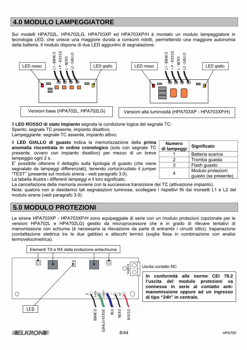
4.0 MODULO LAMPEGGIATORE Sui modelli HPA702L, HPA702LG, HPA703XP ed HPA703XP/H è montato un modulo lampeggiatore in tecnologia LED, che unisce una maggiore durata a consumi ridotti, permettendo una maggiore autonomia della batteria. Il modulo dispone di due LED aggiuntivi di segnalazione.
Il LED ROSSO di stato impianto segnala la condizione logica del segnale TC: Spento: segnale TC presente, impianto disattivo; Lampeggiante: segnale TC assente, impianto attivo;
Il LED GIALLO di guasto indica la memorizzazione della prima anomalia riscontrata in ordine cronologico (solo con segnale TC presente, ovvero con impianto disattivo) per mezzo di un breve lampeggio ogni 2 s. E’ possibile ottenere il dettaglio sulla tipologia di guasto (che viene segnalato da lampeggi differenziati), tenendo cortocircuitato il jumper “TEST” (presente sul modulo sirena - vedi paragrafo 3.0). La tabella illustra i differenti lampeggi e il loro significato. La cancellazione della memoria avviene con la successiva transizione del TC (attivazione impianto). Nota: qualora non si desiderino tali segnalazioni luminose, scollegare i rispettivi fili dai morsetti L1 e L2 del modulo sirena (vedi paragrafo 3.0).
5.0 MODULO PROTEZIONI Le sirene HPA703XP - HPA703XP/H sono equipaggiate di serie con un modulo protezioni (opzionale per le versioni HPA702L e HPA702LG) gestito da microprocessore che è in grado di rilevare tentativi di manomissione con schiuma (è necessaria la rilevazione da parte di entrambi i circuiti ottici), trapanazione (contattazione elettrica tra le due gabbie) e attacchi termici (soglia fissa in combinazione con analisi termovelocimetrica).
D
SAB-
SAB+ - +P
TAMP
ER
Numero di lampeggi Significato
1 Batteria scarica 2 Tromba guasta 3 Flash guasto
4 Modulo protezioni guasto (se presente)
LED
BIAN
CO
GIAA
LO-V
ERDE
BLU
NERO
ROSS
O
Uscita contatto NC
L1 -
BIAN
CO
+ P
- ROS
SO
L - N
ERO
L2 -
GIAL
LO
LED rosso LED giallo LED rosso LED giallo
Versioni base (HPA702L, HPA702LG) Versioni alta luminosità (HPA703XP - HPA703XP/H)
L1 -
BIAN
CO
+ P
- ROS
SO
L - N
ERO
L2 -
GIAL
LO
In conformità alle norme CEI 79.2 l’uscita del modulo protezioni va connessa in serie al contatto anti-manomissione oppure ad un ingresso di tipo “24h” in centrale.
Elementi TX e RX della protezione antischiuma

9/44 HPA700
Sul modulo protezioni è presente un LED verde che provvede a fornire due segnalazioni: Indicazione di allarme sabotaggio (contemporaneo
all’apertura del contatto d’uscita); Memoria di allarme o guasto locale (della prima anomalia
riscontrata in ordine cronologico) mediante lampeggi differenziati.
VERIFICA FUNZIONALE Oscurando con una mano gli elementi TX e RX del modulo o cortocircuitando per un istante i due faston (filo blu e filo giallo-verde) l’intensità del LED verde aumenterà per qualche istante, per poi riportarsi nello stato iniziale. NOTA: La cancellazione della memoria avviene con la successiva transizione del TC (attivazione impianto).
5.1 CONNESSIONI Alimentare la scheda collegando il filo rosso al
morsetto “+P”, il filo nero al morsetto “-“ ed il filo bianco al morsetto “D” del modulo sirena;
Collegare l'uscita tamper del modulo protezioni in serie al contatto antiapertura/antiasportazione oppure ad un ingresso di tipo 24h in centrale, utilizzando i morsetti di appoggio presenti sul modulo sirena;
Inserire il faston con filo blu (SAB+) sul connettore collocato all'interno della gabbia interna di protezione; far passare il faston con filo giallo-verde (SAB-) attraverso l'apposito foro presente sulla gabbia;
Chiudere e fissare con le apposite viti la gabbia interna di protezione; Inserire il faston con filo giallo-verde (SAB-) sul connettore collocato all'interno del coperchio.
Chiudere e fissare con le apposite viti il coperchio esterno.
ATTENZIONE: LE PROTEZIONI ANTISCHIUMA / ANTIPERFORAZIONE SONO OPERATIVE SOLO SE È PRESENTE LA GABBIA INTERNA.
Numero di lampeggi Significato
1 Allarme antischiuma 2 Allarme antiperforazione 3 Allarme termovelocimetrico 4 Guasto antischiuma 5 Guasto termovelocimetrico
D Filo linea dati per il modulo sirena SAB- Filo di connessione al coperchio esternoSAB+ Filo di connessione alla gabbia interna
- Filo negativo di alimentazione +P Filo positivo di alimentazione
TAMPER Contatto sabotaggio (da collegare in serie al micro-interruttore anti-manomissione o ad un ingresso di centrale 24h
Filo giallo-verde Filo giallo-verde Filo blu

10/44 HPA700
6.0 ESEMPIO DI COLLEGAMENTO
A
AP
AP
TEST
B C D E F G H I L
BATT 12V
+ -
BL TC F TA TA D +P
+P
L
L
L1
L1
L2
L2
D
SAB-
SAB+
-
+P
TAMPER
+ -
6K
8
6K
8
Al coperchio esterno
In serie al micro antimanomissione
oppure su ingresso 24h
dedicato
BATTERIA
Alla gabbia interna
BIAN
CO
ROSS
O NE
RO
GIAL
LO
BLU
GIAL
LO-V
ERDE
+ -
Relè
d’alla
rme TC
GUAS
TO 24h
CENTRALE
BIANCO NERO ROSSO
L’esempio si riferisce alle programmazioni di fabbrica (linee bilanciate)
11/44 HPA700
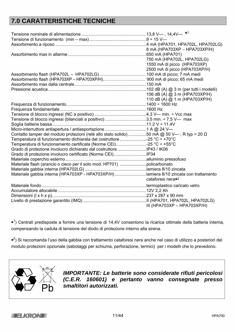
7.0 CARATTERISTICHE TECNICHE Tensione nominale di alimentazione......................................................13,8 V— , 14,4V— *1 Tensione di funzionamento (min – max) ...............................................9 ÷ 15 V— Assorbimento a riposo ...........................................................................4 mA (HPA701, HPA702L, HPA702LG) 8 mA (HPA703XP – HPA703XP/H) Assorbimento max in allarme.................................................................650 mA (HPA701) 750 mA (HPA702L, HPA702LG) 1550 mA di picco (HPA703XP) 2500 mA di picco (HPA703XP/H) Assorbimento flash (HPA702L – HPA702LG).......................................100 mA di picco; 7 mA medi Assorbimento flash (HPA703XP – HPA703XP/H)…………………...…… 900 mA di picco; 65 mA medi Assorbimento max dalla centrale ...........................................................150 mA Pressione acustica .................................................................................102 dB (A) @ 3 m (per tutti i modelli) ...............................................................................................................106 dB (A) @ 3 m (HPA703XP/H) ...............................................................................................................110 dB (A) @ 1 m (HPA703XP/H) Frequenza di funzionamento..................................................................1400 ÷ 1600 Hz Frequenza fondamentale .......................................................................1600 Hz Tensione di blocco ingressi (NC a positivo) ...........................................4,3 V— min. ÷ Vcc max Tensione di blocco ingressi (bilanciati a positivo) ..................................3,5 min. ÷ 7,5 V— max Soglia batteria bassa..............................................................................11.2 V ÷ 11.4V Micro-interruttore antiapertura / antiasportazione ..................................1 A @ 24 V— Contatto tamper del modulo protezioni (relè allo stato solido) ...............50 mA @ 50 V— ; R typ = 20 Ω Temperatura di funzionamento dichiarata dal costruttore......................-25 °C ÷ +70°C Temperatura di funzionamento certificata (Norme CEI).........................-25 °C ÷ +55°C Grado di protezione involucro dichiarato dal costruttore........................IP43 / IK06 Grado di protezione involucro certificato (Norme CEI)...........................IP34 Materiale coperchio esterno...................................................................alluminio pressofuso Materiale flash (arancio o cieco per il solo mod. HP701) ........................policarbonato Materiale gabbia interna (HPA702LG) ...................................................lamiera 8/10 zincata Materiale gabbia interna (HPA703XP - HPA703XP/H) ..........................lamiera 8/10 zincata con trattamento
cataforesi nera*2 Materiale fondo ......................................................................................termoplastico caricato vetro Accumulatore allocabile .........................................................................12V 2,2 Ah Dimensioni (l x h x p)..............................................................................237 x 287 x 90 mm Livello di prestazione garantito (IMQ) ....................................................II (HPA701, HPA702L, HPA702LG) ...............................................................................................................III (HPA703XP – HPA703XP/H) *1) Centrali predisposte a fornire una tensione di 14,4V consentono la ricarica ottimale della batteria interna, compensando la caduta di tensione del diodo di protezione interno alla sirena. *2) Si raccomanda l’uso della gabbia con trattamento cataforesi nera anche nel caso di utilizzo a posteriori del modulo protezioni opzionale (sabotaggi per schiuma, perforazione, termici) per i modelli che lo prevedono.
IMPORTANTE: Le batterie sono considerate rifiuti pericolosi (C.E.R. 160601) e pertanto vanno consegnate presso smaltitori autorizzati.
12/44 HPA700
TABLES DES MATIERES
TABLES DES MATIERES.............................................................................................................. 12 1.0 CARACTERISTIQUES GENERALES....................................................................................... 12
1.1 GESTION ALARMES.......................................................................................................... 13 1.2 AUTODIAGNOSTIC............................................................................................................ 13
2.0 INSTALLATION ........................................................................................................................ 14 3.0 MODULE SIRENE .................................................................................................................... 15
3.1 PROGRAMMATIONS D’USINE.......................................................................................... 16 3.2 PROGRAMMATIONS MODALITES DE SONNERIE.......................................................... 16 3.3 PROGRAMMATIONS TIME OUT SONNERIE ................................................................... 17 3.4 PROGRAMMATIONS TYPE ENTREES............................................................................. 173.5 PROGRAMMATIONS REFERENCE ENTREES ................................................................ 17 3.6 PROGRAMMATIONS COMPTAGE ALARMES.................................................................. 17 3.7 PROGRAMMATIONS FONCTION ECHAFAUDAGE ......................................................... 17
4.0 MODULE CLIGNOTANT .......................................................................................................... 18 5.0 MODULE PROTECTIONS........................................................................................................ 18
5.1 CONNEXIONS.................................................................................................................... 19 6.0 EXEMPLE DE RACCORDEMENT ........................................................................................... 20 7.0 CARACTERISTIQUES TECHNIQUES..................................................................................... 21 8.0 MAINTENANCE PREVENTIVE ............................................................................................... 22 9.0 EXPLOITATION........................................................................................................................ 22
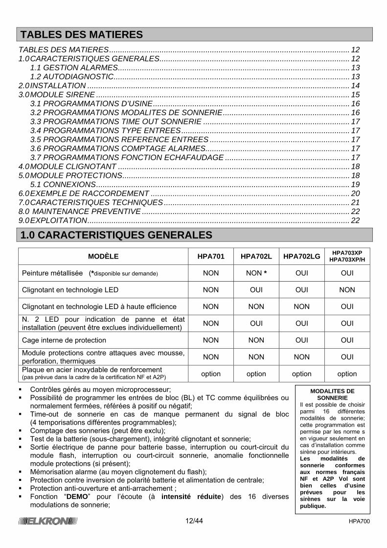
1.0 CARACTERISTIQUES GENERALES
MODÈLE HPA701 HPA702L HPA702LG HPA703XP HPA703XP/H
Peinture métallisée (*disponible sur demande) NON NON * OUI OUI
Clignotant en technologie LED NON OUI OUI NON
Clignotant en technologie LED à haute efficience NON NON NON OUI
N. 2 LED pour indication de panne et état installation (peuvent être exclues individuellement) NON OUI OUI OUI
Cage interne de protection NON NON OUI OUI
Module protections contre attaques avec mousse, perforation, thermiques NON NON NON OUI
Plaque en acier inoxydable de renforcement (pas prévue dans la cadre de la certification NF et A2P) option option option option
Contrôles gérés au moyen microprocesseur; Possibilité de programmer les entrées de bloc (BL) et TC comme équilibrées ou
normalement fermées, référées à positif ou négatif; Time-out de sonnerie en cas de manque permanent du signal de bloc
(4 temporisations différentes programmables); Comptage des sonneries (peut être exclu); Test de la batterie (sous-chargement), intégrité clignotant et sonnerie; Sortie électrique de panne pour batterie basse, interruption ou court-circuit du
module flash, interruption ou court-circuit sonnerie, anomalie fonctionnelle module protections (si présent);
Mémorisation alarme (au moyen clignotement du flash); Protection contre inversion de polarité batterie et alimentation de centrale; Protection anti-ouverture et anti-arrachement ; Fonction “DEMO” pour l’écoute (à intensité réduite) des 16 diverses
modulations de sonnerie;
MODALITES DE SONNERIE
Il est possible de choisir parmi 16 différentes modalités de sonnerie; cette programmation est permise par les norme s en vigueur seulement en cas d’installation comme sirène pour intérieurs. Les modalités de sonnerie conformes aux normes français NF et A2P Vol sont bien celles d’usine prévues pour les sirènes sur la voie publique.
13/44 HPA700
Fonction de bloc initial; Fonction état installation pour “échafaudage”; Clignotant en technologie LED; Contrôle du courant absorbé par la centrale (limitation à 150 mA).
Note*. Ajouter le module de protections à posteriori nécessite l’utilisation de la cage avec traitement “cataphorèse”.
1.1 GESTION ALARMES Après avoir câblé correctement et refermé les deux entrées (fonction de bloc au power-on), la sirène génère une alarme uniquement quand vient à manquer à la fois le signal d’état installation “TC” (signal présent = installation désactivée) et le signal de bloc alarme “BL”. L’absence d’un seul des deux ne provoque aucun événement d’alarme; pour bloquer une alarme en cours, il suffit de fournir le signal de bloc. Dans le cas où le signal de bloc reste ouvert longtemps, intervient le timeout programmé au moyen des pontets spéciaux qui se charge de faire cesser la sonnerie. Une fois bloqué l’alarme, le flash continue à clignoter (chaque 2,5 s environ). La sirène reste dans cet état de mémorisation alarme tant que le signal TC n’est pas fourni (l’installation s’éteint). NOTE: En cas de batterie déchargée (en-dessous du seuil de 11,2V), le clignotement du flash est interrompu pour préserver l’énergie restante en faveur de l’alarme acoustique. Pour compléter les prestations de la sirène sont disponibles, au moyen de pontets spécialement prévus, deux fonctions supplémentaires: Comptage alarmes et Fonction Échafaudage (Pour tout détail sur le fonctionnement voir les paragraphes 3.6 et 3.7). Dans le cas où la centrale ne dispose pas d’une sortie d’état installation il est nécessaire de raccorder avec les deux signaux de BL et TC, sachant que de cette façon on perd une partie des prestations offertes (mémoire alarme, comptage alarmes, fonction échafaudage). NOTE: Il est indispensable de connecter la batterie tampon car, en étant limité l’Consommation de courant de la centrale, sans celle-ci la sirène n’est pas en mesure de sonner.
1.2 AUTODIAGNOSTIC Les sirènes de la famille HPA700 utilisent une fonction innovatrice de “autodiagnostic actif” qui se charge de vérifier l’intégrité de la batterie, de l’haut parleur, du clignotant et du module protections (si présent). Ce test est effectué à chaque activation installation (ouverture de l’entrée TC) et dure 2 secondes; dans cet intervalle de temps sont sollicités l’haut parleur et le flash et est effectuée une mesure sous charge de la tension de batterie, en fournissant donc d’éventuelles indications d’anomalie au moyen la sortie “panne”. De cette façon on a toujours un contrôle de la fonctionnalité totale de la sirène à chaque activation de l’installation. Un test analogue est également effectué à chaque début et fin d’alarme; à la différence du précédent, celui-ci est instantané car la batterie est déjà sous charge. L’indication d’anomalie est donc mise à jour seulement dans ces trois conditions. D ‘éventuelles pannes sont également signalées au moyen de LED jaune locale (présente sur le module clignotant), qui toutefois est visible seulement avec installation désactivé (l’allumage est activé seulement avec TC présent en visualisant seulement la première anomalie rencontrée en ordre chronologique). NOTE: Au cas où on utilise une unique commande pour BL et TC la sonnerie est retardée de 2 secondes.
14/44 HPA700
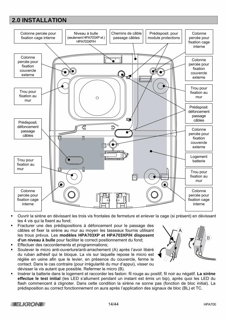
2.0 INSTALLATION
Ouvrir la sirène en dévissant les trois vis frontales de fermeture et enlever la cage (si présent) en dévissant
les 4 vis qui la fixent au fond; Fracturer une des prédispositions à défoncement pour le passage des
câbles et fixer la sirène au mur au moyen les tasseaux fournis utilisant les trous prévus. Les modèles HPA703XP et HPA703XP/H disposent d’un niveau à bulle pour faciliter le correct positionnement du fond;
Effectuer des raccordements et programmations; Soulever le micro anti-ouverture/anti-arrachement (A) après l’avoir libéré
du ruban adhésif qui le bloque. La vis sur laquelle repose le micro est réglée en usine afin que le levier, en présence du couvercle, ferme le contact. Dans le cas contraire (pour irrégularité du mur d’appui), visser ou dévisser la vis autant que possible. Refermer le micro (B).
Insérer la batterie dans le logement et raccorder les faston: fil rouge au positif, fil noir au négatif. La sirène effectue le test initial (les LED s’allument pendant un instant est émis un bip), après quoi les LED du flash commencent à clignoter. Dans cette condition la sirène ne sonne pas (fonction de bloc initial). La prédisposition au correct fonctionnement on aura après l’application des signaux de bloc (BL) et TC.
Colonne percée pour fixation cage interne
Colonne percée pour fixation cage
interne
Colonne percée pour
fixation couvercle externe
Colonne percée pour
fixation couvercle externe
Colonne percée pour
fixation couvercle externe
Colonne percée pour fixation cage
interne
Colonne percée pour fixation cage
interne
Niveau à bulle (seulement HPA703XP et )
HPA703XP/H
Trou pour fixation au
mur
Trou pour fixation au mur
Trou pour fixation au
mur Trou pour fixation au
mur
Prédisposit. défoncement
passage câbles
Chemins de câble passage câbles
Prédisposit. défoncement
passage câbles
Logement batterie
Prédisposit. pour module protections
15/44 HPA700
3.0 MODULE SIRÈNE
A
AP
AP
TEST
B C D E F G H I L
BATT 12V
+ - BL TC F TA TA D +P L L1 L2
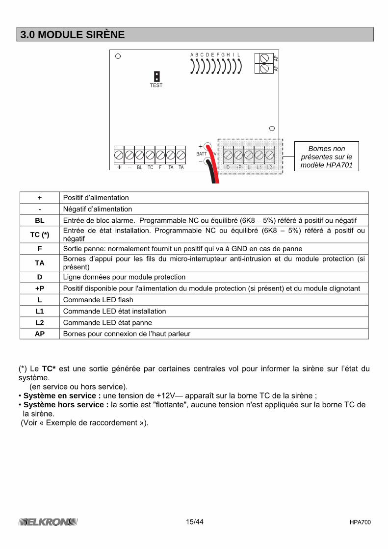
+ Positif d’alimentation - Négatif d’alimentation
BL Entrée de bloc alarme. Programmable NC ou équilibré (6K8 – 5%) référé à positif ou négatif
TC (*) Entrée de état installation. Programmable NC ou équilibré (6K8 – 5%) référé à positif ou négatif
F Sortie panne: normalement fournit un positif qui va à GND en cas de panne
TA Bornes d’appui pour les fils du micro-interrupteur anti-intrusion et du module protection (si présent)
D Ligne données pour module protection +P Positif disponible pour l'alimentation du module protection (si présent) et du module clignotant L Commande LED flash
L1 Commande LED état installation L2 Commande LED état panne AP Bornes pour connexion de l’haut parleur
(*) Le TC* est une sortie générée par certaines centrales vol pour informer la sirène sur l’état du système. (en service ou hors service). • Système en service : une tension de +12V— apparaît sur la borne TC de la sirène ; • Système hors service : la sortie est "flottante", aucune tension n'est appliquée sur la borne TC de la sirène. (Voir « Exemple de raccordement »).
Bornes non présentes sur le modèle HPA701
16/44 HPA700
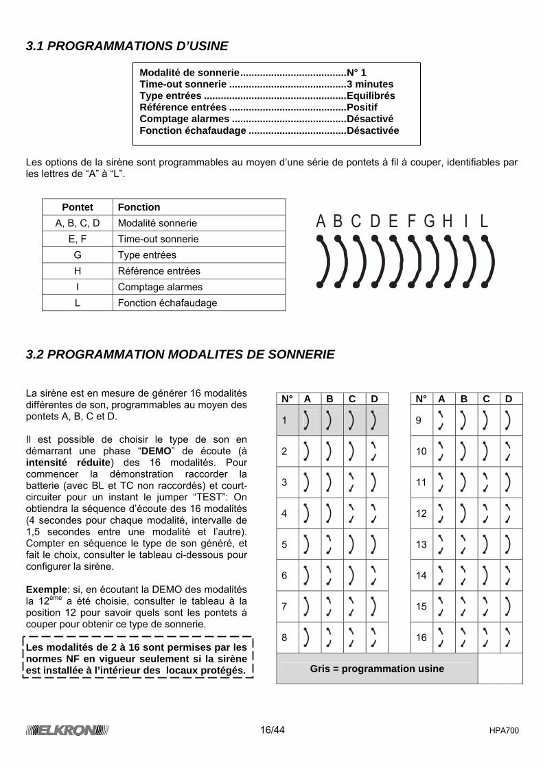
3.1 PROGRAMMATIONS D’USINE Les options de la sirène sont programmables au moyen d’une série de pontets à fil à couper, identifiables par les lettres de “A” à “L”.
A B C D E F G H I L
3.2 PROGRAMMATION MODALITES DE SONNERIE La sirène est en mesure de générer 16 modalités différentes de son, programmables au moyen des pontets A, B, C et D. Il est possible de choisir le type de son en démarrant une phase “DEMO” de écoute (à intensité réduite) des 16 modalités. Pour commencer la démonstration raccorder la batterie (avec BL et TC non raccordés) et court-circuiter pour un instant le jumper “TEST”: On obtiendra la séquence d’écoute des 16 modalités (4 secondes pour chaque modalité, intervalle de 1,5 secondes entre une modalité et l’autre). Compter en séquence le type de son généré, et fait le choix, consulter le tableau ci-dessous pour configurer la sirène. Exemple: si, en écoutant la DEMO des modalités la 12ème a été choisie, consulter le tableau à la position 12 pour savoir quels sont les pontets à couper pour obtenir ce type de sonnerie. Les modalités de 2 à 16 sont permises par les normes NF en vigueur seulement si la sirène est installée à l’intérieur des locaux protégés.
Pontet Fonction A, B, C, D Modalité sonnerie
E, F Time-out sonnerie G Type entrées H Référence entrées I Comptage alarmes L Fonction échafaudage
N° A B C D N° A B C D
1
9
2
10
3
11
4
12
5
13
6
14
7
15
8
16
Gris = programmation usine
Modalité de sonnerie......................................N° 1 Time-out sonnerie ..........................................3 minutes Type entrées ...................................................Equilibrés Référence entrées ..........................................Positif Comptage alarmes .........................................Désactivé Fonction échafaudage ...................................Désactivée
17/44 HPA700
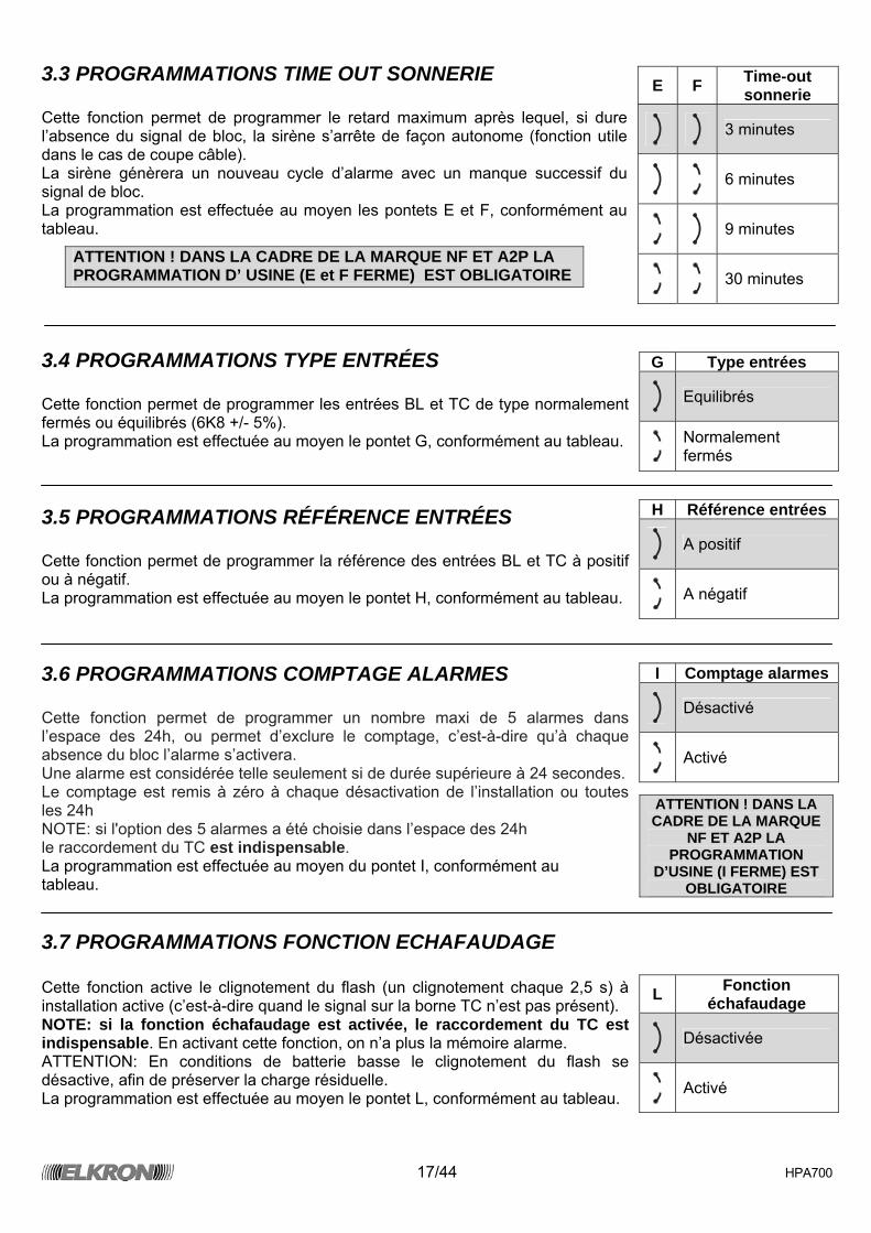
3.3 PROGRAMMATIONS TIME OUT SONNERIE Cette fonction permet de programmer le retard maximum après lequel, si dure l’absence du signal de bloc, la sirène s’arrête de façon autonome (fonction utile dans le cas de coupe câble). La sirène génèrera un nouveau cycle d’alarme avec un manque successif du signal de bloc. La programmation est effectuée au moyen les pontets E et F, conformément au tableau.
3.4 PROGRAMMATIONS TYPE ENTRÉES Cette fonction permet de programmer les entrées BL et TC de type normalement fermés ou équilibrés (6K8 +/- 5%). La programmation est effectuée au moyen le pontet G, conformément au tableau.
3.5 PROGRAMMATIONS RÉFÉRENCE ENTRÉES Cette fonction permet de programmer la référence des entrées BL et TC à positif ou à négatif. La programmation est effectuée au moyen le pontet H, conformément au tableau.
3.6 PROGRAMMATIONS COMPTAGE ALARMES Cette fonction permet de programmer un nombre maxi de 5 alarmes dans l’espace des 24h, ou permet d’exclure le comptage, c’est-à-dire qu’à chaque absence du bloc l’alarme s’activera. Une alarme est considérée telle seulement si de durée supérieure à 24 secondes. Le comptage est remis à zéro à chaque désactivation de l’installation ou toutes les 24h NOTE: si l'option des 5 alarmes a été choisie dans l’espace des 24h le raccordement du TC est indispensable. La programmation est effectuée au moyen du pontet I, conformément au tableau.
3.7 PROGRAMMATIONS FONCTION ECHAFAUDAGE Cette fonction active le clignotement du flash (un clignotement chaque 2,5 s) à installation active (c’est-à-dire quand le signal sur la borne TC n’est pas présent). NOTE: si la fonction échafaudage est activée, le raccordement du TC est indispensable. En activant cette fonction, on n’a plus la mémoire alarme. ATTENTION: En conditions de batterie basse le clignotement du flash se désactive, afin de préserver la charge résiduelle. La programmation est effectuée au moyen le pontet L, conformément au tableau.
E F Time-out sonnerie
3 minutes
6 minutes
9 minutes
30 minutes ATTENTION ! DANS LA CADRE DE LA MARQUE NF ET A2P LA PROGRAMMATION D’ USINE (E et F FERME) EST OBLIGATOIRE
G Type entrées
Equilibrés
Normalement fermés
H Référence entrées
A positif
A négatif
I Comptage alarmes
Désactivé
Activé
ATTENTION ! DANS LA CADRE DE LA MARQUE
NF ET A2P LA PROGRAMMATION
D’USINE (I FERME) EST OBLIGATOIRE
L Fonction échafaudage
Désactivée
Activé
18/44 HPA700
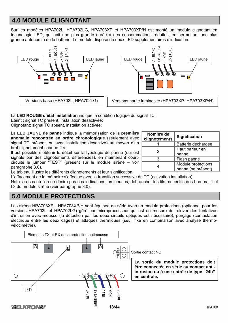
4.0 MODULE CLIGNOTANT
Sur les modèles HPA702L, HPA702LG, HPA703XP et HPA703XP/H est monté un module clignotant en technologie LED, qui unit une plus grande durée à des consommations réduites, en permettant une plus grande autonomie de la batterie. Le module dispose de deux LED supplémentaires d’indication.
La LED ROUGE d’état installation indique la condition logique du signal TC: Eteint : signal TC présent, installation désactivée; Clignotant: signal TC absent, installation activée;
La LED JAUNE de panne indique la mémorisation de la première anomalie rencontrée en ordre chronologique (seulement avec signal TC présent, ou avec installation désactive) au moyen d’un bref clignotement chaque 2 s. Il est possible d’obtenir le détail sur la typologie de panne (qui est signalé par des clignotements différenciés), en maintenant court-circuité le jumper “TEST” (présent sur le module sirène – voir paragraphe 3.0). Le tableau illustre les différents clignotements et leur signification. L’effacement de la mémoire s’effectue avec la transition successive du TC (activation installation). Note: au cas où l’on ne désire pas ces indications lumineuses, débrancher les fils respectifs des bornes L1 et L2 du module sirène (voir paragraphe 3.0).
5.0 MODULE PROTECTIONS
Les sirène HPA703XP - HPA703XP/H sont équipée de série avec un module protections (optionnel pour les versions HPA702L et HPA702LG) géré par microprocesseur qui est en mesure de relever des tentatives d’intrusion avec mousse (la détection par les deux circuits optiques est nécessaire), perçage (contactation électrique entre les deux cages) et attaques thermiques (seuil fixe en combinaison avec analyse thermo-vélocimétrie).
D
SAB-
SAB+ - +P
TAMP
ER
Nombre de clignotements Signification
1 Batterie déchargée
2 Haut parleur en panne
3 Flash panne
4 Module protections panne (se présent)
LED
BLAN
C
JAUN
E-VE
RT
BLEU
NOIR
ROUG
E
Sortie contact NC
L1 -
BLAN
C +
P - R
OUGE
L -
NOI
R L2
- JA
UNE
LED rouge LED jaune LED rouge LED jaune
Versions base (HPA702L, HPA702LG) Versions haute luminosité (HPA703XP- HPA703XP/H)
L1 -
BLAN
C +
P - R
OUGE
L -
NOI
R L2
- JA
UNE
La sortie du module protections doit être connectée en série au contact anti-intrusion ou à une entrée de type “24h” en centrale.
Éléments TX et RX de la protection antimousse
19/44 HPA700
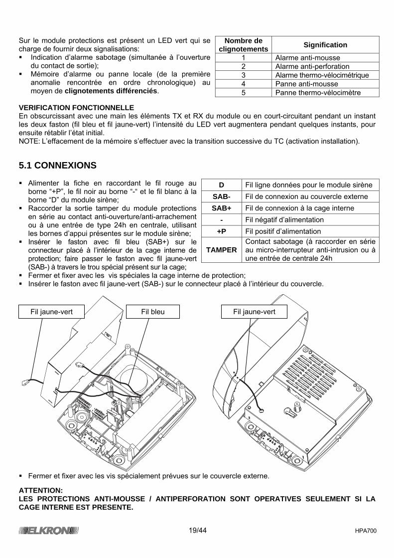
Sur le module protections est présent un LED vert qui se charge de fournir deux signalisations: Indication d’alarme sabotage (simultanée à l’ouverture
du contact de sortie); Mémoire d’alarme ou panne locale (de la première
anomalie rencontrée en ordre chronologique) au moyen de clignotements différenciés.
VERIFICATION FONCTIONNELLE En obscurcissant avec une main les éléments TX et RX du module ou en court-circuitant pendant un instant les deux faston (fil bleu et fil jaune-vert) l’intensité du LED vert augmentera pendant quelques instants, pour ensuite rétablir l’état initial. NOTE: L’effacement de la mémoire s’effectuer avec la transition successive du TC (activation installation).
5.1 CONNEXIONS Alimenter la fiche en raccordant le fil rouge au
borne “+P”, le fil noir au borne “-“ et le fil blanc à la borne “D” du module sirène;
Raccorder la sortie tamper du module protections en série au contact anti-ouverture/anti-arrachement ou à une entrée de type 24h en centrale, utilisant les bornes d’appui présentes sur le module sirène;
Insérer le faston avec fil bleu (SAB+) sur le connecteur placé à l’intérieur de la cage interne de protection; faire passer le faston avec fil jaune-vert (SAB-) à travers le trou spécial présent sur la cage;
Fermer et fixer avec les vis spéciales la cage interne de protection; Insérer le faston avec fil jaune-vert (SAB-) sur le connecteur placé à l’intérieur du couvercle.
Fermer et fixer avec les vis spécialement prévues sur le couvercle externe.
ATTENTION: LES PROTECTIONS ANTI-MOUSSE / ANTIPERFORATION SONT OPERATIVES SEULEMENT SI LA CAGE INTERNE EST PRESENTE.
Nombre de clignotements Signification
1 Alarme anti-mousse 2 Alarme anti-perforation 3 Alarme thermo-vélocimétrique 4 Panne anti-mousse 5 Panne thermo-vélocimètre
D Fil ligne données pour le module sirène SAB- Fil de connexion au couvercle externe SAB+ Fil de connexion à la cage interne
- Fil négatif d’alimentation +P Fil positif d’alimentation
TAMPER Contact sabotage (à raccorder en série au micro-interrupteur anti-intrusion ou à une entrée de centrale 24h
Fil jaune-vertFil jaune-vert Fil bleu
20/44 HPA700
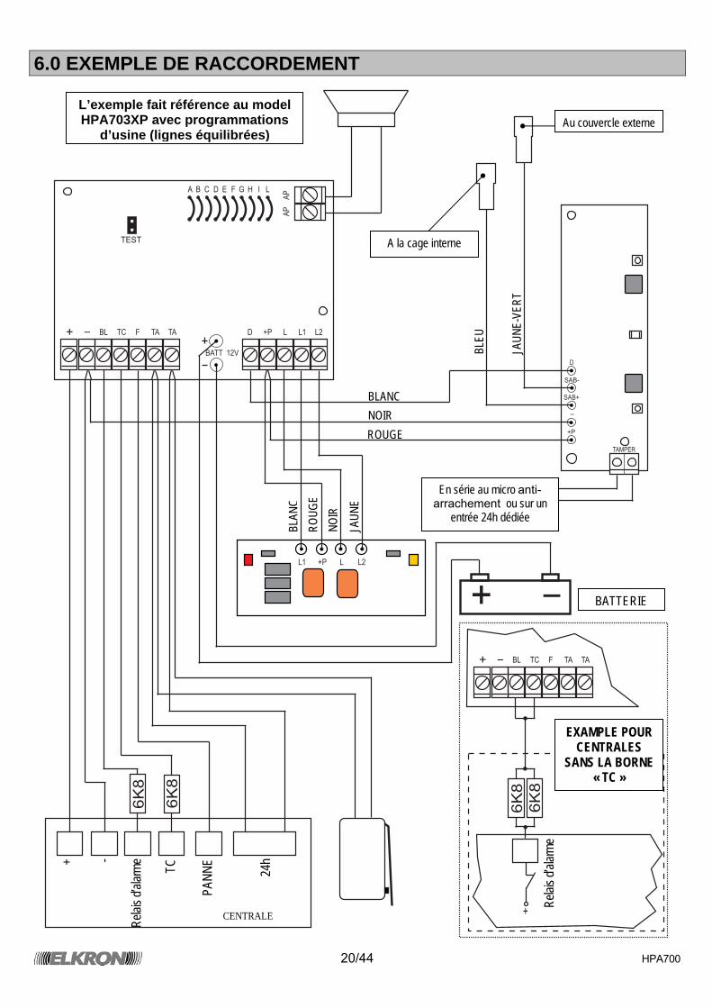
6.0 EXEMPLE DE RACCORDEMENT
A
AP
AP
TEST
B C D E F G H I L
BATT 12V
+ -
BL TC F TA TA D +P
+P
L
L
L1
L1
L2
L2
D
SAB-
SAB+
-
+P
TAMPER
+ -
6K
8
6K
8
BL TC F TA TA+
+
-
6K
8
6K
8
Au couvercle externe
En série au micro anti-arrachement ou sur un
entrée 24h dédiée
BATTERIE
A la cage interne
BLAN
C RO
UGE
NOIR
JAUN
E
BLEU
JAUN
E-VE
RT
+ -
Relai
s d’al
arme TC
PANN
E
24h
CENTRALE
BLANC NOIR ROUGE
L’exemple fait référence au model HPA703XP avec programmations
d’usine (lignes équilibrées)
EXAMPLE POUR CENTRALES
SANS LA BORNE « TC »
Relai
s d’al
arme
21/44 HPA700
7.0 CARACTERISTIQUES TECHNIQUES
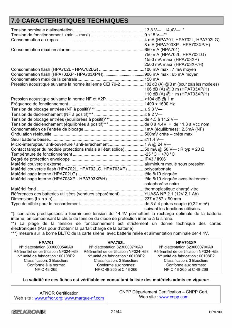
Tension nominale d’alimentation............................................................13,8 V— , 14,4V— * Tension de fonctionnement (mini – maxi) .............................................9 ÷15 V—** Consommation au repos ........................................................................4 mA (HPA701, HPA702L, HPA702LG) 8 mA (HPA703XP - HPA703XP/H) Consommation maxi en alarme..............................................................650 mA (HPA701) 750 mA (HPA702L, HPA702LG) 1550 mA maxi (HPA703XP) 2500 mA maxi (HPA703XP/H) Consommation flash (HPA702L - HPA702LG) ......................................100 mA maxi; 7 mA moyen Consommation flash (HPA703XP - HPA703XP/H)......................................900 mA maxi; 65 mA moyen Consommation maxi de la centrale........................................................150 mA Pression acoustique suivante la norme italienne CEI 79-2 ....................102 dB (A) @ 3 m (pour tous les modeles) ...............................................................................................................106 dB (A) @ 3 m (HPA703XP/H) ...............................................................................................................110 dB (A) @ 1 m (HPA703XP/H) Pression acoustique suivante la norme NF et A2P................................>104 dB @ 1 m Fréquence de fonctionnement ...............................................................1400 ÷ 1600 Hz Tension de blocage entrées (NF à positif)*** .........................................≥ 9,3 V— Tension de déclenchement (NF à positif)*** ..........................................≤ 9,2 V— Tension de blocage entrées (équilibrées à positif)***.............................de 4,5 à 11,2 V— Tension de déclenchement (équilibrées à positif)***..............................de 0 à 4,4V ÷ de 11,3 à Vcc nom. Consommation de l’entrée de blocage...................................................1mA (équilibrées) ; 2,5mA (NF) Ondulation résiduelle .............................................................................500mV crête – crête maxi Seuil batterie basse................................................................................≤11.4 V— Micro-interrupteur anti-ouverture / anti-arrachement..............................1 A @ 24 V— Contact tamper du module protections (relais à l’état solide) ................50 mA @ 50 V— ; R typ = 20 Ω Température de fonctionnement ............................................................-25 °C ÷ +70 °C Degré de protection enveloppe ..............................................................IP43 / IK06 Matériel couvercle externe .....................................................................aluminium moulé sous pression Matériel couvercle flash (HPA702L, HPA702LG, HPA703XP) ..............polycarbonate Matériel cage interne (HPA702LG) ........................................................tôle 8/10 zinguée Matériel cage interne (HPA703XP - HPA703XP/H) ...............................tôle 8/10 zinguée aves traitement
cataphorèse noire Matériel fond ..........................................................................................thermoplastique chargé vitre Références des batteries utilisées (vendues séparément) ....................YUASA NP 2.1 (12V 2,1 Ah) Dimensions (l x h x p).............................................................................237 x 287 x 90 mm Type de câble pour le raccordement......................................................de 3 à 4 paires souple (0,22 mm²)
suivant les fonctions utilisées. *): centrales prédisposées à fournir une tension de 14,4V permettent la recharge optimale de la batterie interne, en compensant la chute de tension du diode de protection interne à la sirène. **) La plage de la tension de fonctionnement est strictement un donne technique des cartes électroniques (Pas pour d’obtenir la parfait charge de la batterie). ***) mesuré sur la borne BL/TC de la carte sirène, avec batterie reliée et alimentation nominale de14.4V.
HPA701 Nº d'attestation 3030000540A0
Référentiel de certification NF324-H58 Nº unité de fabrication : 00108P2
Classification: 3 Boucliers Conforme à la norme:
NF-C 48-265
HPA702L Nº d'attestation 3230000710A0
Référentiel de certification NF324-H58 Nº unité de fabrication : 00108P2
Classification: 3 Boucliers Conforme aux normes:
NF-C 48-265 et C 48-266
HPA703XP Nº d'attestation 3230000700A0
Référentiel de certification NF324-H58 Nº unité de fabrication : 00108P2
Classification: 3 Boucliers Conforme aux normes:
NF-C 48-265 et C 48-266
La validité de ces fiches est vérifiable en consultant la liste des matériels admis en vigueur:
AFNOR Certification
Web site : www.afnor.org; www.marque-nf.com CNPP Département Certification – CNPP Cert.
Web site : www.cnpp.com
22/44 HPA700
8.0 MAINTENANCE PREVENTIVE Il est nécessaire de vérifier périodiquement: -l'état de serrage des vis de fixation du boîtier; -l'état des différentes connexions et l'état de la boucle d'autoprotection; -l'état de charge de la batterie interne; -l'état du boîtier (traces d'oxydation). 9.0 EXPLOITATION Aucune autre action d'exploitation que la mise en service et l'arrêt du système d'alarme auquel est relié ce dispositif n'est assuré par l'utilisateur. Toutes les mises en oeuvre, pose et maintenance courante ne peuvent être effectuées que par un personnel technique qualifié. En cas de défaut permanent de la boucle d'autoprotection ou de dysfonctionnement, contacter immédiatement l'installateur.
IMPORTANT: Les batteries sont considérées des déchets dangereux (C.E.D. 160601) et par conséquent elles doivent être traitées par des services autorisés.
23/44 HPA700
LIST OF CONTENTS LIST OF CONTENTS.........................................................................................................................................23 1.0 GENERAL CHARACTERISTICS .................................................................................................................23
1.1 ALARMS MANAGEMENT........................................................................................................................23 1.2 SELF-DIAGNOSTICS ..............................................................................................................................24
2.0 INSTALLATION............................................................................................................................................25 3.0 SIREN MODULE..........................................................................................................................................26
3.1 FACTORY PROGRAMMING ...................................................................................................................27 3.2 SOUND MODE PROGRAMMING............................................................................................................27 3.3 SOUND TIME OUT PROGRAMMING .....................................................................................................28 3.4 INPUT TYPE PROGRAMMING ...............................................................................................................28 3.5 INPUT REFERENCE PROGRAMMING ..................................................................................................28 3.6 ALARMS COUNT PROGRAMMING........................................................................................................28 3.7 SCAFFOLDS FUNCTION PROGRAMMING ...........................................................................................28
4.0 FLASHLIGHT MODULE...............................................................................................................................29 5.0 PROTECTION MODULE .............................................................................................................................29 6.0 EXAMPLE OF CONNECTION .....................................................................................................................31 7.0 TECHNICAL CHARACTERISTICS..............................................................................................................32
1.0 GENERAL CHARACTERISTICS
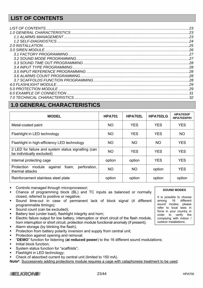
MODEL HPA701 HPA702L HPA702LG HPA703XP HPA703XP/H
Metal-coated paint NO YES YES YES
Flashlight in LED technology NO YES YES NO
Flashlight in high-efficiency LED technology NO NO NO YES
2 LED for failure and system status signalling (can be individually excluded) NO YES YES YES
Internal protecting cage option option YES YES
Protection module against foam, perforation, thermal attacks NO NO option YES
Reinforcement stainless steel plate option option option option Controls managed through microprocessor; Chance of programming block (BL) and TC inputs as balanced or normally
closed, referred to positive or negative; Sound time-out in case of permanent lack of block signal (4 different
programmable timings); Sound count (can be excluded); Battery test (under load), flashlight integrity and horn; Electric failure output for low battery, interruption or short circuit of the flash module,
horn interruption or short circuit, protection module functional anomaly (if present); Alarm storage (by blinking the flash); Protection from battery polarity inversion and supply from central unit; Protection against opening and removal; “DEMO” function for listening (at reduced power) to the 16 different sound modulations; Initial block function; System status function for “scaffolds”; Flashlight in LED technology; Check of absorbed current by central unit (limited to 150 mA).
Note*. Successively adding protections module requires a cage with cataphoresis treatment to be used.
SOUND MODES
It is possible to choose among 16 different sound modes; please refer to local laws in force in your country in order to verify the complying with indoor / outdoor installations.
24/44 HPA700
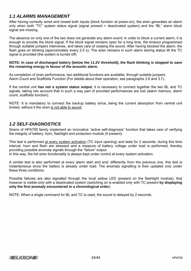
1.1 ALARMS MANAGEMENT After having correctly wired and closed both inputs (block function at power-on), the siren generates an alarm only when both “TC” system status signal (signal present = deactivated system) and the “BL” alarm block signal are missing. The absence on only one of the two does not generate any alarm event; in order to block a current alarm, it is enough to provide the block signal. If the block signal remains open for a long time, the timeout programmed through suitable jumpers intervenes, and takes care of ceasing the sound. After having blocked the alarm, the flash goes on blinking (approximately every 2.5 s). The siren remains in such alarm storing status till the TC signal is provided (the system is turned off). NOTE: In case of discharged battery (below the 11.2V threshold), the flash blinking is stopped to save the remaining energy in favour of the acoustic alarm. As completion of siren performance, two additional functions are available, through suitable jumpers: Alarm Count and Scaffolds Function (For details about their operation, see paragraphs 3.6 and 3.7). If the central unit has not a system status output, it is necessary to connect together the two BL and TC signals, taking into account that in such a way part of provided performances are lost (alarm memory, alarm count, scaffolds function). NOTE: It is mandatory to connect the backup battery since, being the current absorption from central unit limited, without it the siren is not able to sound.
1.2 SELF-DIAGNOSTICS Sirens of HPA700 family implement an innovative “active self-diagnosis” function that takes care of verifying the integrity of battery, horn, flashlight and protection module (if present). This test is performed at every system activation (TC input opening) and lasts for 2 seconds; during this time interval, horn and flash are stressed and a measure of battery voltage under load is performed, thereby providing possible anomaly signals through the “failure” output. In this way, the full siren functionality is always kept under control at every system activation. A similar test is also performed at every alarm start and end; differently from the previous one, this test is instantaneous since the battery is already under load. The anomaly signalling is then updated only under these three conditions. Possible failures are also signalled through the local yellow LED (present on the flashlight module), that however is visible only with a deactivated system (switching on is enabled only with TC present by displaying only the first anomaly encountered in a chronological order). NOTE: When a single command for BL and TC is used, the sound is delayed by 2 seconds.
25/44 HPA700
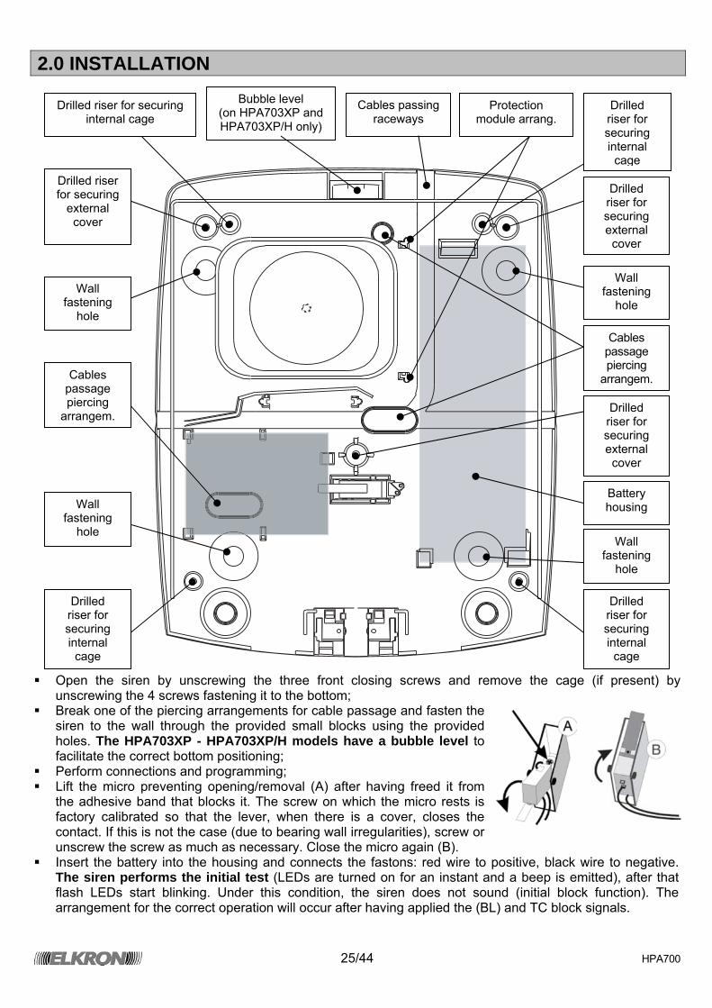
2.0 INSTALLATION
Open the siren by unscrewing the three front closing screws and remove the cage (if present) by
unscrewing the 4 screws fastening it to the bottom; Break one of the piercing arrangements for cable passage and fasten the
siren to the wall through the provided small blocks using the provided holes. The HPA703XP - HPA703XP/H models have a bubble level to facilitate the correct bottom positioning;
Perform connections and programming; Lift the micro preventing opening/removal (A) after having freed it from
the adhesive band that blocks it. The screw on which the micro rests is factory calibrated so that the lever, when there is a cover, closes the contact. If this is not the case (due to bearing wall irregularities), screw or unscrew the screw as much as necessary. Close the micro again (B).
Insert the battery into the housing and connects the fastons: red wire to positive, black wire to negative. The siren performs the initial test (LEDs are turned on for an instant and a beep is emitted), after that flash LEDs start blinking. Under this condition, the siren does not sound (initial block function). The arrangement for the correct operation will occur after having applied the (BL) and TC block signals.
Drilled riser for securing internal cage
Drilled riser for securing internal
cage
Drilled riser for securing external cover
Drilled riser for securing external cover
Drilled riser for securing
external cover
Drilled riser for securing internal
cage
Drilled riser for securing internal
cage
Bubble level (on HPA703XP and HPA703XP/H only)
Wall fastening
hole
Wall fastening
hole
Wall fastening
hole Wall
fastening hole
Cables passage piercing
arrangem.
Cables passing raceways
Cables passage piercing
arrangem.
Battery housing
Protection module arrang.

26/44 HPA700
3.0 SIREN MODULE
A
AP
AP
TEST
B C D E F G H I L
BATT 12V
+ - BL TC F TA TA D +P L L1 L2
+ Supply positive - Supply negative
BL Alarm block input. Programmable NC or balanced (6K8 – 5%) referred to positive or negative TC System status input. Programmable NC or balanced (6K8 – 5%) referr. to positive or negative F Failure output: it normally provides a positive that goes to GND in case of failure
TA Bearing terminals for micro-switch wires against tampering and protecting module wires (if present)
D Data line for protecting module +P Positive available for protecting module supply (if present) and flashlight module L LED flash LED command
L1 System status LED command L2 Failure status LED command AP Horn connecting terminals
Terminals not mounted on
HPA701 model
27/44 HPA700
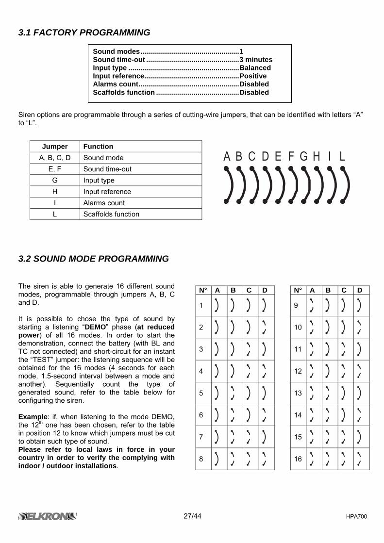
3.1 FACTORY PROGRAMMING Siren options are programmable through a series of cutting-wire jumpers, that can be identified with letters “A” to “L”.
A B C D E F G H I L
3.2 SOUND MODE PROGRAMMING The siren is able to generate 16 different sound modes, programmable through jumpers A, B, C and D. It is possible to chose the type of sound by starting a listening “DEMO” phase (at reduced power) of all 16 modes. In order to start the demonstration, connect the battery (with BL and TC not connected) and short-circuit for an instant the “TEST” jumper: the listening sequence will be obtained for the 16 modes (4 seconds for each mode, 1.5-second interval between a mode and another). Sequentially count the type of generated sound, refer to the table below for configuring the siren. Example: if, when listening to the mode DEMO, the 12th one has been chosen, refer to the table in position 12 to know which jumpers must be cut to obtain such type of sound. Please refer to local laws in force in your country in order to verify the complying with indoor / outdoor installations.
Jumper Function A, B, C, D Sound mode
E, F Sound time-out G Input type H Input reference I Alarms count L Scaffolds function
N° A B C D N° A B C D
1
9
2
10
3
11
4
12
5
13
6
14
7
15
8
16
Sound modes..................................................1 Sound time-out ...............................................3 minutes Input type ........................................................Balanced Input reference................................................Positive Alarms count...................................................Disabled Scaffolds function ..........................................Disabled
28/44 HPA700
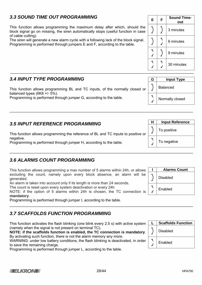
3.3 SOUND TIME OUT PROGRAMMING This function allows programming the maximum delay after which, should the block signal go on missing, the siren automatically stops (useful function in case of cable cutting). The siren will generate a new alarm cycle with a following lack of the block signal. Programming is performed through jumpers E and F, according to the table.
3.4 INPUT TYPE PROGRAMMING This function allows programming BL and TC inputs, of the normally closed or balanced types (6K8 +/- 5%). Programming is performed through jumper G, according to the table.
3.5 INPUT REFERENCE PROGRAMMING This function allows programming the reference of BL and TC inputs to positive or negative. Programming is performed through jumper H, according to the table.
3.6 ALARMS COUNT PROGRAMMING This function allows programming a max number of 5 alarms within 24h, or allows excluding the count, namely upon every block absence, an alarm will be generated. An alarm is taken into account only if its length is more than 24 seconds. The count is reset upon every system deactivation or every 24h NOTE: if the option of 5 alarms within 24h is chosen, the TC connection is mandatory. Programming is performed through jumper I, according to the table.
3.7 SCAFFOLDS FUNCTION PROGRAMMING This function activates the flash blinking (one blink every 2.5 s) with active system (namely when the signal is not present on terminal TC). NOTE: if the scaffolds function is enabled, the TC connection is mandatory. By activating such function, there is not the alarm memory any more. WARNING: under low battery conditions, the flash blinking is deactivated, in order to save the remaining charge. Programming is performed through jumper L, according to the table.
E F Sound Time-out
3 minutes
6 minutes
9 minutes
30 minutes
G Input Type
Balanced
Normally closed
H Input Reference
To positive
To negative
I Alarms Count
Disabled
Enabled
L Scaffolds Function
Disabled
Enabled
29/44 HPA700
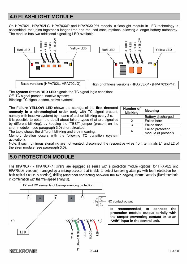
4.0 FLASHLIGHT MODULE On HPA702L, HPA702LG, HPA703XP and HPA703XP/H models, a flashlight module in LED technology is assembled, that joins together a longer time and reduced consumptions, allowing a longer battery autonomy. The module has two additional signalling LED available.
The System Status RED LED signals the TC signal logic condition: Off: TC signal present, inactive system; Blinking: TC signal absent, active system; The Failure YELLOW LED shows the storage of the first detected anomaly in a chronological order (only with TC signal present, namely with inactive system) by means of a short blinking every 2 s. It is possible to obtain the detail about failure types (that are signalled by different blinking), by keeping the “TEST” jumper (present on the siren module – see paragraph 3.0) short-circuited. The table shows the different blinking and their meaning. Memory deletion occurs with the following TC transition (system activation). Note: if such luminous signalling are not wanted, disconnect the respective wires from terminals L1 and L2 of the siren module (see paragraph 3.0).
5.0 PROTECTION MODULE The HPA703XP - HPA703XP/H sirens are equipped as series with a protection module (optional for HPA702L and HPA702LG versions) managed by a microprocessor that is able to detect tampering attempts with foam (detection from both optical circuits is needed), drilling (electrical contacting between the two cages), thermal attacks (fixed threshold in combination with thermal-speed analysis).
D
SAB-
SAB+ - +P
TAMP
ER
Number of blinking Meaning
1 Battery discharged 2 Failed horn 3 Failed flash
4 Failed protection module (if present)
LED
WHI
TE
YELL
OW--G
REEN
BLUE
BLAC
K
RED
NC contact output
L1 -
WHI
TE
+ P
- RED
L -
BLA
CK
L2 -
YEL
LOW
Red LED Yellow LED Red LED Yellow LED
Basic versions (HPA702L, HPA702LG) High brightness versions (HPA703XP - (HPA703XP/H)
L1 -
WHI
TE
+ P
- RED
L -
BLA
CK
L2 -
YELL
OW
Is recommended to connect the protection module output serially with the tamper-preventing contact or to an “24h” input in the central unit.
TX and RX elements of foam-preventing protection
30/44 HPA700
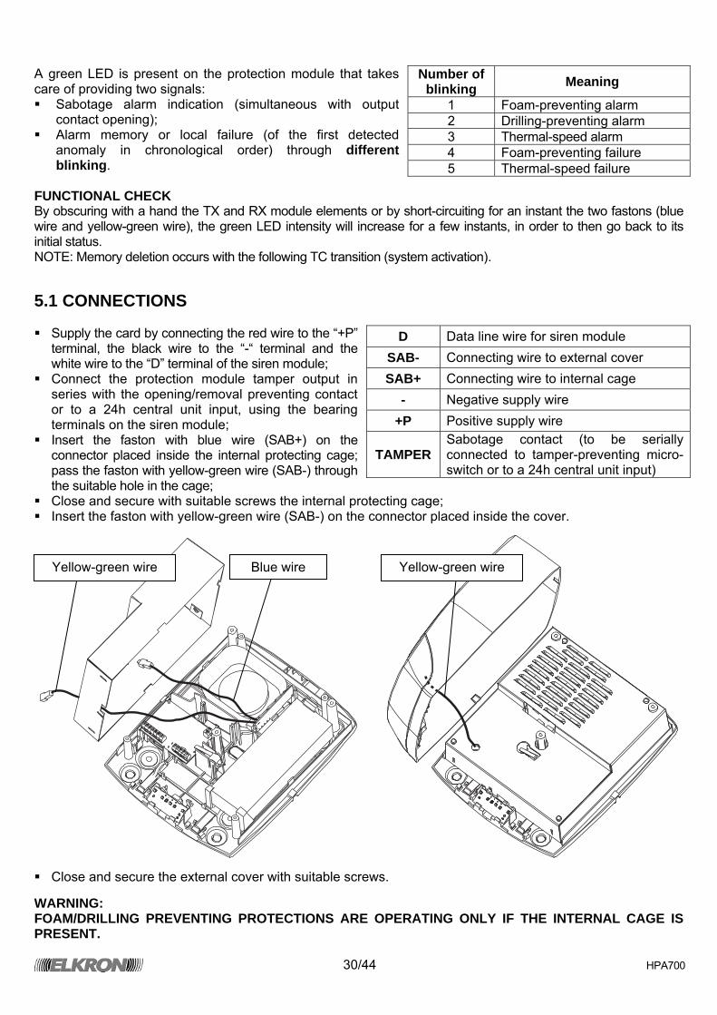
A green LED is present on the protection module that takes care of providing two signals: Sabotage alarm indication (simultaneous with output
contact opening); Alarm memory or local failure (of the first detected
anomaly in chronological order) through different blinking.
FUNCTIONAL CHECK By obscuring with a hand the TX and RX module elements or by short-circuiting for an instant the two fastons (blue wire and yellow-green wire), the green LED intensity will increase for a few instants, in order to then go back to its initial status. NOTE: Memory deletion occurs with the following TC transition (system activation).
5.1 CONNECTIONS Supply the card by connecting the red wire to the “+P”
terminal, the black wire to the “-“ terminal and the white wire to the “D” terminal of the siren module;
Connect the protection module tamper output in series with the opening/removal preventing contact or to a 24h central unit input, using the bearing terminals on the siren module;
Insert the faston with blue wire (SAB+) on the connector placed inside the internal protecting cage; pass the faston with yellow-green wire (SAB-) through the suitable hole in the cage;
Close and secure with suitable screws the internal protecting cage; Insert the faston with yellow-green wire (SAB-) on the connector placed inside the cover.
Close and secure the external cover with suitable screws.
WARNING: FOAM/DRILLING PREVENTING PROTECTIONS ARE OPERATING ONLY IF THE INTERNAL CAGE IS PRESENT.
Number of blinking Meaning
1 Foam-preventing alarm 2 Drilling-preventing alarm 3 Thermal-speed alarm 4 Foam-preventing failure 5 Thermal-speed failure
D Data line wire for siren module SAB- Connecting wire to external cover SAB+ Connecting wire to internal cage
- Negative supply wire +P Positive supply wire
TAMPER Sabotage contact (to be serially connected to tamper-preventing micro-switch or to a 24h central unit input)
Yellow-green wire Yellow-green wire Blue wire
31/44 HPA700
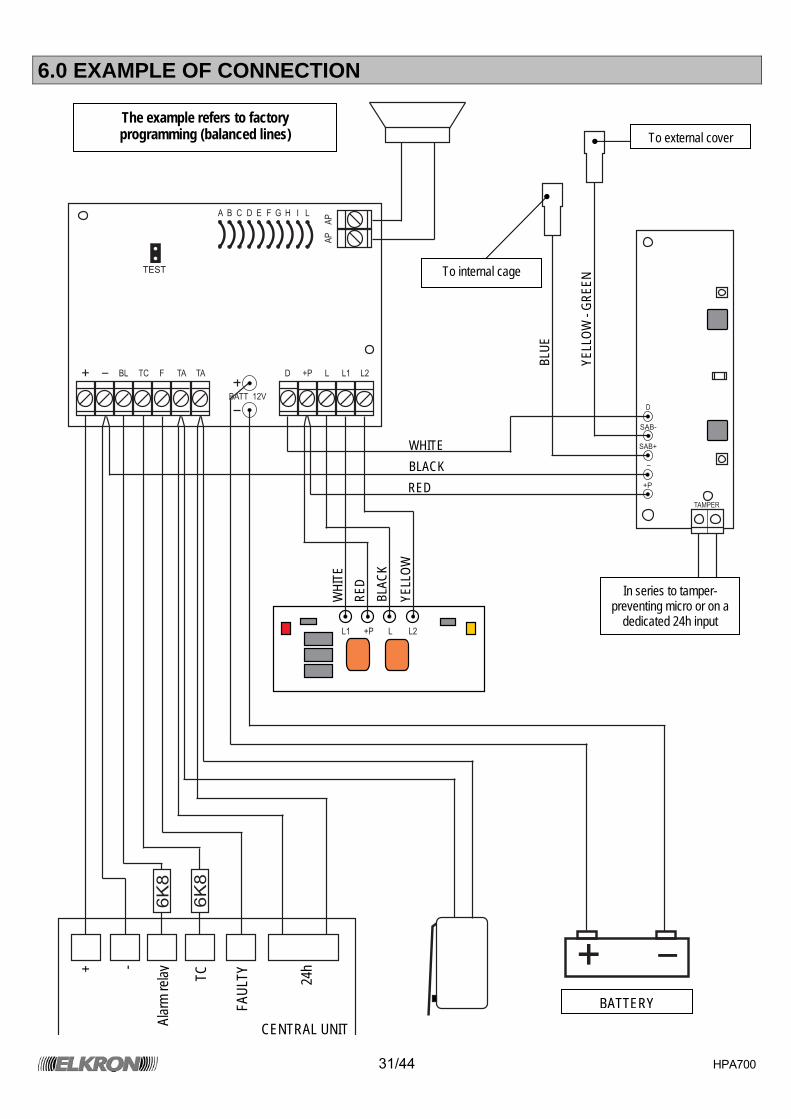
6.0 EXAMPLE OF CONNECTION
A
AP
AP
TEST
B C D E F G H I L
BATT 12V
+ -
BL TC F TA TA D +P
+P
L
L
L1
L1
L2
L2
D
SAB-
SAB+
-
+P
TAMPER
+ -
6K
8
6K
8
To external cover
In series to tamper-preventing micro or on a
dedicated 24h input
BATTERY
To internal cage
WHI
TE
RED
BLAC
K
YELL
OW
BLUE
YELL
OW -
GREE
N
+ -
Alar
m re
la y TC
FAUL
TY 24h
CENTRAL UNIT
WHITE BLACK RED
The example refers to factory programming (balanced lines)
32/44 HPA700
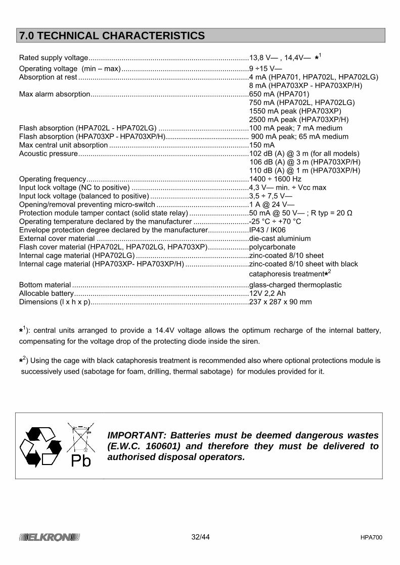
7.0 TECHNICAL CHARACTERISTICS Rated supply voltage..............................................................................13,8 V— , 14,4V— *1 Operating voltage (min – max) ..............................................................9 ÷15 V— Absorption at rest ...................................................................................4 mA (HPA701, HPA702L, HPA702LG) 8 mA (HPA703XP - HPA703XP/H) Max alarm absorption.............................................................................650 mA (HPA701) 750 mA (HPA702L, HPA702LG) 1550 mA peak (HPA703XP) 2500 mA peak (HPA703XP/H) Flash absorption (HPA702L - HPA702LG) ............................................100 mA peak; 7 mA medium Flash absorption (HPA703XP - HPA703XP/H)............................................. 900 mA peak; 65 mA medium Max central unit absorption ....................................................................150 mA Acoustic pressure...................................................................................102 dB (A) @ 3 m (for all models) 106 dB (A) @ 3 m (HPA703XP/H) ...............................................................................................................110 dB (A) @ 1 m (HPA703XP/H) Operating frequency...............................................................................1400 ÷ 1600 Hz Input lock voltage (NC to positive) .........................................................4,3 V— min. ÷ Vcc max Input lock voltage (balanced to positive) ................................................3,5 ÷ 7,5 V— Opening/removal preventing micro-switch .............................................1 A @ 24 V— Protection module tamper contact (solid state relay) .............................50 mA @ 50 V— ; R typ = 20 Ω Operating temperature declared by the manufacturer ...........................-25 °C ÷ +70 °C Envelope protection degree declared by the manufacturer....................IP43 / IK06 External cover material ..........................................................................die-cast aluminium Flash cover material (HPA702L, HPA702LG, HPA703XP)....................polycarbonate Internal cage material (HPA702LG) .......................................................zinc-coated 8/10 sheet Internal cage material (HPA703XP- HPA703XP/H) ...............................zinc-coated 8/10 sheet with black
cataphoresis treatment*2 Bottom material ......................................................................................glass-charged thermoplastic Allocable battery.....................................................................................12V 2,2 Ah Dimensions (l x h x p).............................................................................237 x 287 x 90 mm *1): central units arranged to provide a 14.4V voltage allows the optimum recharge of the internal battery, compensating for the voltage drop of the protecting diode inside the siren. *2) Using the cage with black cataphoresis treatment is recommended also where optional protections module is successively used (sabotage for foam, drilling, thermal sabotage) for modules provided for it.
IMPORTANT: Batteries must be deemed dangerous wastes (E.W.C. 160601) and therefore they must be delivered to authorised disposal operators.
33/44 HPA700
INHALTSVERZEICHNIS
INHALTSVERZEICHNIS....................................................................................................................................33 1.0 ALLGEMEINE MERKMALE .........................................................................................................................33 1.1 ALARMVERWALTUNG ...............................................................................................................................33 1.2 SELBSTDIAGNOSE ....................................................................................................................................34 2.0 INSTALLATION............................................................................................................................................35 3.0 SIRENENMODUL ........................................................................................................................................36 3.1 AB FABRIK ERFOLGTE ROGRAMMIERUNG............................................................................................37 3.2 PROGRAMMIERUNG: MODALITÄT SIRENENGEHEUL ...........................................................................37 3.3 PROGRAMMIERUNG: TIME OUT SIRENENGEHEUL...............................................................................38 3.4 PROGRAMMIERUNG: TYP EINGÄNGE....................................................................................................38 3.5 PROGRAMMIERUNGI: BEZUG EINGÄNGE ..............................................................................................38 3.6 PROGRAMMIERUNG: ZÄHLUNG ALARME...............................................................................................38 3.7 PROGRAMMIERUNG: FUNKTION BAUGERÜST......................................................................................38 4.0 BLINKER-MODUL........................................................................................................................................39 5.0 SCHUTZMODUL..........................................................................................................................................39 6.0 ANSCHLUSSBEISPIEL ...............................................................................................................................41 7.0 TECHNISCHE MERKMALE.........................................................................................................................42
1.0 ALLGEMEINE MERKMALE
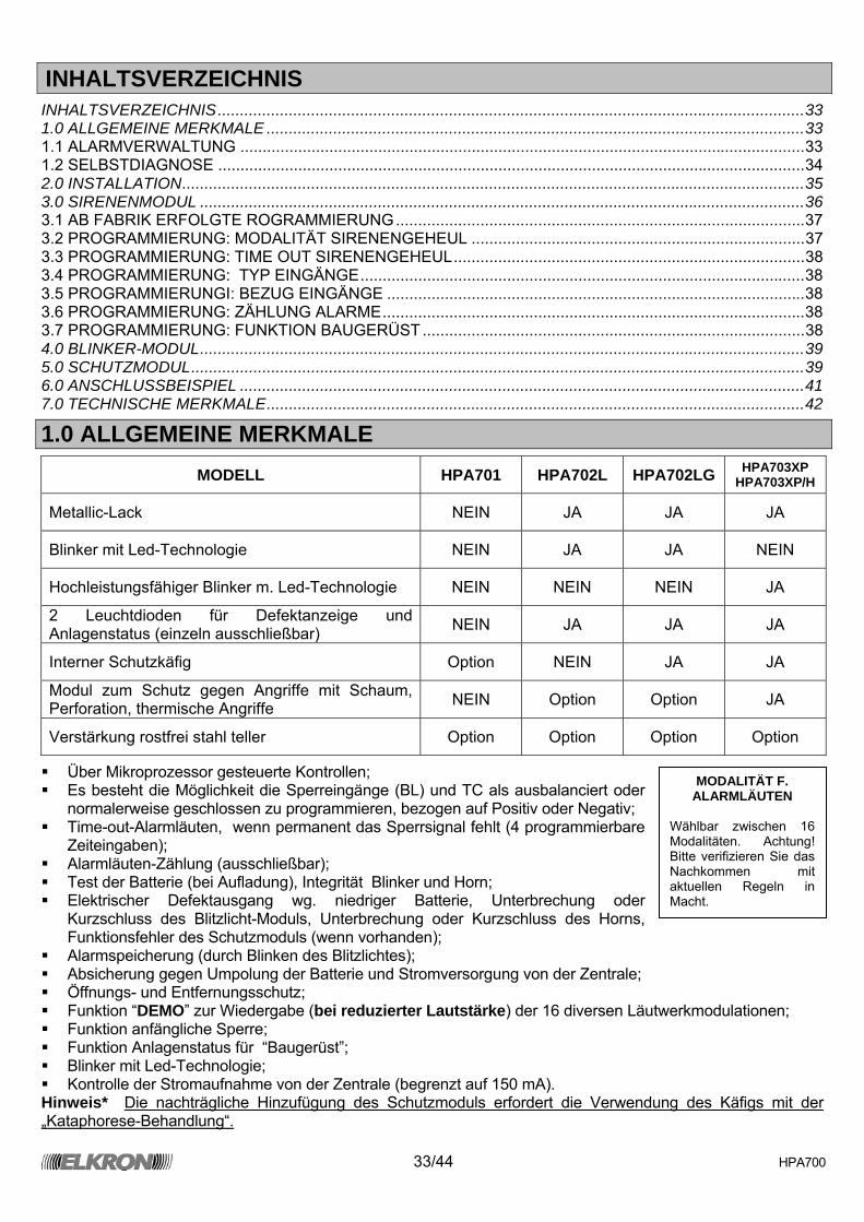
MODELL HPA701 HPA702L HPA702LG HPA703XP HPA703XP/H
Metallic-Lack NEIN JA JA JA
Blinker mit Led-Technologie NEIN JA JA NEIN
Hochleistungsfähiger Blinker m. Led-Technologie NEIN NEIN NEIN JA
2 Leuchtdioden für Defektanzeige und Anlagenstatus (einzeln ausschließbar) NEIN JA JA JA
Interner Schutzkäfig Option NEIN JA JA
Modul zum Schutz gegen Angriffe mit Schaum, Perforation, thermische Angriffe NEIN Option Option JA
Verstärkung rostfrei stahl teller Option Option Option Option
Über Mikroprozessor gesteuerte Kontrollen; Es besteht die Möglichkeit die Sperreingänge (BL) und TC als ausbalanciert oder
normalerweise geschlossen zu programmieren, bezogen auf Positiv oder Negativ; Time-out-Alarmläuten, wenn permanent das Sperrsignal fehlt (4 programmierbare
Zeiteingaben); Alarmläuten-Zählung (ausschließbar); Test der Batterie (bei Aufladung), Integrität Blinker und Horn; Elektrischer Defektausgang wg. niedriger Batterie, Unterbrechung oder
Kurzschluss des Blitzlicht-Moduls, Unterbrechung oder Kurzschluss des Horns, Funktionsfehler des Schutzmoduls (wenn vorhanden);
Alarmspeicherung (durch Blinken des Blitzlichtes); Absicherung gegen Umpolung der Batterie und Stromversorgung von der Zentrale; Öffnungs- und Entfernungsschutz; Funktion “DEMO” zur Wiedergabe (bei reduzierter Lautstärke) der 16 diversen Läutwerkmodulationen; Funktion anfängliche Sperre; Funktion Anlagenstatus für “Baugerüst”; Blinker mit Led-Technologie; Kontrolle der Stromaufnahme von der Zentrale (begrenzt auf 150 mA).
Hinweis* Die nachträgliche Hinzufügung des Schutzmoduls erfordert die Verwendung des Käfigs mit der „Kataphorese-Behandlung“.
MODALITÄT F. ALARMLÄUTEN
Wählbar zwischen 16 Modalitäten. Achtung! Bitte verifizieren Sie das Nachkommen mit aktuellen Regeln in Macht.
34/44 HPA700
1.1 ALARMVERWALTUNG Nach einwandfreier Verkabelung und Schließung beider Eingänge (Sperrfunktion Power-on) erzeugt die Sirene nur dann einen Alarm, wenn sowohl das Signal für Anlagenstatus “TC” fehlt (Signal vorhanden = Anlage abgeschaltet), als auch das Signal für Alarmsperre “BL”. Das Fehlen von nur einem der beiden Signale verursacht kein Alarmereignis; um einen gerade ablaufenden Alarm zu blockieren genügt es das Sperrsignal zu liefern. Bleibt ein Sperrsignal lange geöffnet, greift die mit zweckmäßigen Brücken programmierte Timeout-Vorrichtung ein und schaltet den Alarm ab. Nachdem der Alarm blockiert wurde, blinkt das Blitzlicht weiter (alle 2,5 Sek ca.). Die Sirene verbleibt in diesem Zustand der Alarmspeicherung bis das TC-Signal geliefert wird (Anlage schaltet sich aus). Hinweis: Bei leerer Batterie (Ladevolumen unter 11,2 V) wird das Blitzlichtblinken unterbrochen, um die restliche Energie für den akustischen Alarm aufzubewahren. Zwei zusätzliche Funktionen, durch zweckmäßige Brücken, werden die Leistungen der Sirene wie folgt komplettiert: Zählung der Alarme und Baugerüstfunktion (weitere Einzelheiten zur Funktionsweise: s. Punkt 3.6 und 3.7). Sollte die Zentrale nicht über einen Anlagenstatus-Ausgang verfügen, müssen die beiden Signale BL und TC zusammen angeschlossen werden, wobei zu beachten ist, dass auf diese Art und Weise ein Teil der angebotenen Leistungen verloren geht (Alarmspeicher, Alarmzählung, Baugerüstfunktion). HINWEIS: Die Ergänzungsbatterie muss unbedingt angeschlossen werden wegen der begrenzten Stromabsorption von der Zentrale, da ohne diesen Anschluss die Sirene nicht in Alarmbereitschaft steht.
1.2 SELBSTDIAGNOSE Die Sirenen der Bauserie HPA700 beinhalten eine innovative Funktion: die “Aktive Selbstdiagnose”. Diese überprüft die Integrität der Batterie, des Horns, Blinkers und des Schutzmoduls (wenn eingebaut). Dieser zwei Sekunden dauernde Test wird bei jeder Aktivierung der Anlage durchgeführt (Öffnung des Eingangs TC). In diesem Zeitintervall werden Horn und Blitzlicht angeregt, es erfolgt eine Messung unter Belastung der Batteriespannung; die eventuellen Defektanzeigen werden vom Ausgang “Defekt” signalisiert. Bei jeder Aktivierung der Anlage ist dadurch eine konstante Kontrolle über die komplette Funktionalität der Sirene gegeben. Ein ähnlicher Test erfolgt auch bei jedem Alarmbeginn und –ende. Im Gegensatz zum o.g. Test, erfolgt dieser augenblicklich, da die Batterie bereits unter Belastung steht. Die Anzeige bzgl. der Anomalien wird demnach nur unter diesen drei Bedingungen aktualisiert. Eventuelle Defekte werden auch durch die lokale gelbe Led signalisiert (befindet sich auf dem Blinkermodul); diese ist aber nur bei abgeschalteter Anlage sichtbar (die Freigabe zum Aufleuchten der Led erfolgt nur in Gegenwart von TC, wobei nur die erste chronologisch stattgefundene Anomalie visualisiert wird). Hinweis: Wird für BL und TC nur ein einziger Befehl verwendet, verzögert sich der Alarmton um 2 Sekunden.
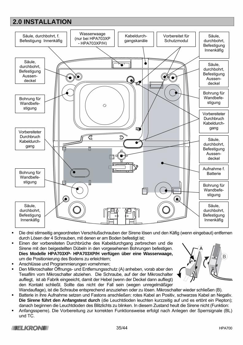
35/44 HPA700
2.0 INSTALLATION
Die drei stirnseitig angeordneten Verschlußschrauben der Sirene lösen und den Käfig (wenn eingebaut) entfernen
durch Lösen der 4 Schrauben, mit denen er am Boden befestigt ist; Einen der vorbereiteten Durchbrüche des Kabeldurchgang zerbrechen und die
Sirene mit den beigestellten Dübeln in den vorgesehenen Bohrungen befestigen. Dies Modelle HPA703XP- HPA703XP/H verfügen über eine Wasserwaage, um die Positionierung des Bodens zu erleichtern;
Anschlüsse und Programmierungen vornehmen; Den Mikroschalter Öffnungs- und Entfernungsschutz (A) anheben, vorab aber den
Tesafilm vom Mikroschalter abziehen. Die Schraube, auf der der Mikroschalter aufliegt, ist ab Fabrik eingeeicht, damit der Hebel (wenn der Deckel dann aufliegt) den Kontakt schließt. Sollte das nicht der Fall sein (wegen unregelmäßiger Wandauflage), ist die Schraube entsprechend anzuziehen oder zu lösen. Mikroschalter wieder schließen (B).
Batterie in ihre Aufnahme setzen und Fastons anschließen: rotes Kabel an Positiv, schwarzes Kabel an Negativ. Die Sirene führt den Anfangstest durch (die Leuchtdioden leuchten kurzzeitig auf und es ertönt ein Piepton); danach beginnen die Leuchtdioden des Blitzlichts zu blinken. In diesem Zustand heult die Sirene nicht (Funktion:
Anfangssperre). Die Vorbereitung zur korrekten Funktionsweise erfolgt nach Anlegen der Sperrsignale (BL) und TC.
Säule, durchbohrt, f. Befestigung Innenkäfig
Säule, durchbohrt, Befestigung Innenkäfig
Säule, durchbohrt, Befestigung
Aussen-deckel
Säule, durchbohrt, Befestigung
Aussen-deckel
Säule, durchbohrt, Befestigung
Aussen-deckel
Säule, durchbohrt, Befestigung Innenkäfig
Säule, durchbohrt, Befestigung Innenkäfig
Wasserwaage (nur bei HPA703XP
- HPA703XP/H)
Bohrung für Wandbefe-
stigung
Bohrung für Wandbefe-
stigung
Bohrung für Wandbefe-
stigung Bohrung für Wandbefe-
stigung
Vorbereiteter Durchbruch Kabeldurch-
gang
Kabeldurch- gangskanäle
Vorbereiteter Durchbruch Kabeldurch-
gang
Aufnahme f. Batterie
Vorbereitet für Schutzmodul

36/44 HPA700
3.0 SIRENENMODUL
A
AP
AP
TEST
B C D E F G H I L
BATT 12V
+ - BL TC F TA TA D +P L L1 L2
+ Positiv der Stromversorgung - Negativ der Stromversorgung
BL Eingang Alarmsperre. Programmierbar NC oder ausbalanciert (6K8 – 5%) bezogen auf Positiv oder Negativ
TC Eingang Anlagenstatus. Programmierbar NC oder ausbalanciert (6K8 – 5%) bezogen auf Positiv oder Negativ
F Ausgang Defekt: liefert normalerweise ein positives Signal, das im Fall eines Defekts an GDN geht
TA Stützklemmen für die Drähte des Mikroschalters Sabotageschutz und des Schutzmoduls (wenn eingebaut)
D Datenleitung für Schutzmodul
+P Positiv, verfügbar für die Stromversorgung des Schutzmoduls (wenn eingebaut) und des Blinkermoduls
L Befehl Led Blitzlicht L1 Befehl Led Anlagenstatus L2 Befehl Led Defektstatus AP Anschlußklemmen f. Horn
Modell HPA701 ohne diese Klemmen
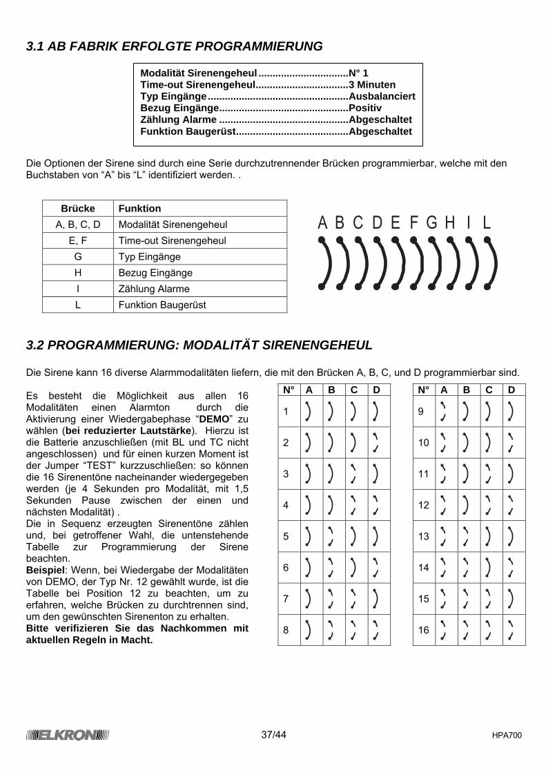
37/44 HPA700
3.1 AB FABRIK ERFOLGTE PROGRAMMIERUNG Die Optionen der Sirene sind durch eine Serie durchzutrennender Brücken programmierbar, welche mit den Buchstaben von “A” bis “L” identifiziert werden. .
A B C D E F G H I L
3.2 PROGRAMMIERUNG: MODALITÄT SIRENENGEHEUL Die Sirene kann 16 diverse Alarmmodalitäten liefern, die mit den Brücken A, B, C, und D programmierbar sind. Es besteht die Möglichkeit aus allen 16 Modalitäten einen Alarmton durch die Aktivierung einer Wiedergabephase “DEMO” zu wählen (bei reduzierter Lautstärke). Hierzu ist die Batterie anzuschließen (mit BL und TC nicht angeschlossen) und für einen kurzen Moment ist der Jumper “TEST” kurzzuschließen: so können die 16 Sirenentöne nacheinander wiedergegeben werden (je 4 Sekunden pro Modalität, mit 1,5 Sekunden Pause zwischen der einen und nächsten Modalität) . Die in Sequenz erzeugten Sirenentöne zählen und, bei getroffener Wahl, die untenstehende Tabelle zur Programmierung der Sirene beachten. Beispiel: Wenn, bei Wiedergabe der Modalitäten von DEMO, der Typ Nr. 12 gewählt wurde, ist die Tabelle bei Position 12 zu beachten, um zu erfahren, welche Brücken zu durchtrennen sind, um den gewünschten Sirenenton zu erhalten. Bitte verifizieren Sie das Nachkommen mit aktuellen Regeln in Macht.
Brücke Funktion A, B, C, D Modalität Sirenengeheul
E, F Time-out Sirenengeheul G Typ Eingänge H Bezug Eingänge I Zählung Alarme L Funktion Baugerüst
N° A B C D N° A B C D
1
9
2
10
3
11
4
12
5
13
6
14
7
15
8
16
Modalität Sirenengeheul ................................N° 1 Time-out Sirenengeheul.................................3 Minuten Typ Eingänge..................................................Ausbalanciert Bezug Eingänge..............................................Positiv Zählung Alarme ..............................................Abgeschaltet Funktion Baugerüst........................................Abgeschaltet
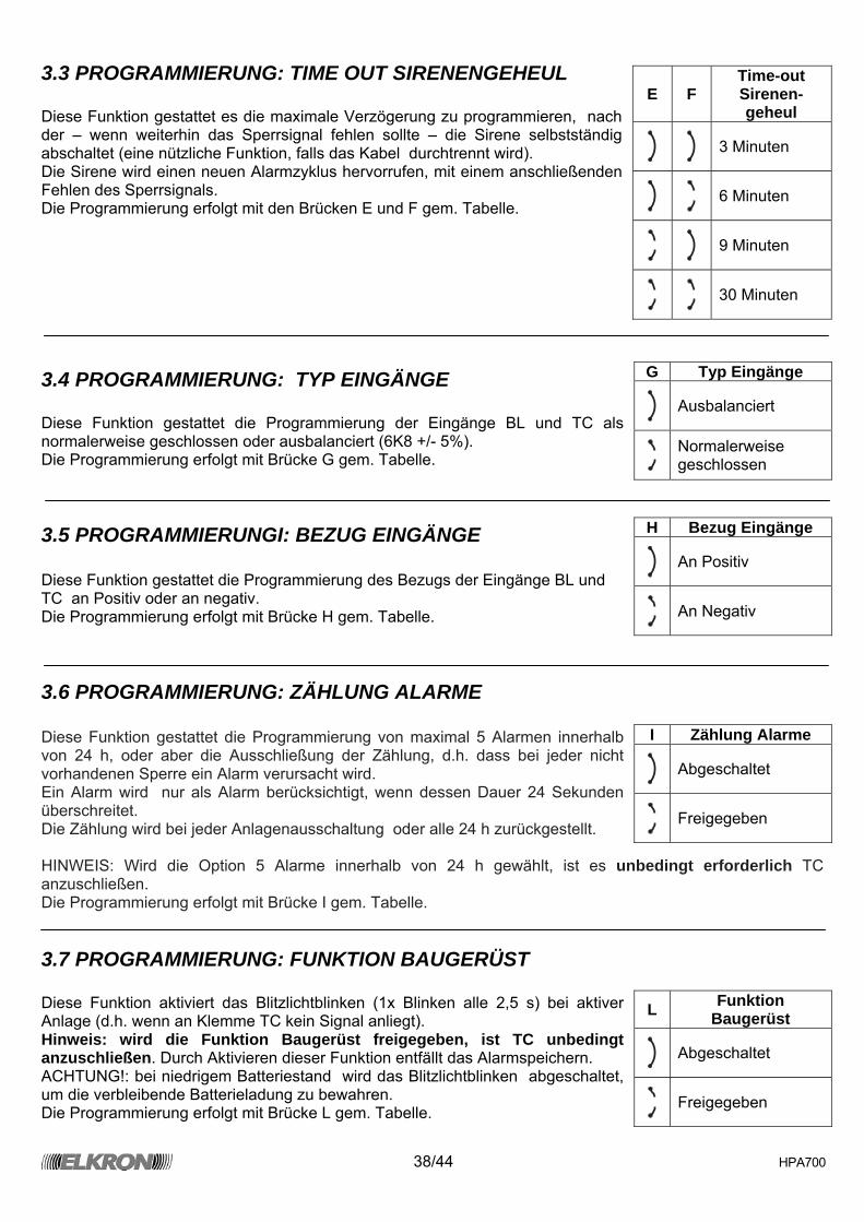
38/44 HPA700
3.3 PROGRAMMIERUNG: TIME OUT SIRENENGEHEUL Diese Funktion gestattet es die maximale Verzögerung zu programmieren, nach der – wenn weiterhin das Sperrsignal fehlen sollte – die Sirene selbstständig abschaltet (eine nützliche Funktion, falls das Kabel durchtrennt wird). Die Sirene wird einen neuen Alarmzyklus hervorrufen, mit einem anschließenden Fehlen des Sperrsignals. Die Programmierung erfolgt mit den Brücken E und F gem. Tabelle.
3.4 PROGRAMMIERUNG: TYP EINGÄNGE Diese Funktion gestattet die Programmierung der Eingänge BL und TC als normalerweise geschlossen oder ausbalanciert (6K8 +/- 5%). Die Programmierung erfolgt mit Brücke G gem. Tabelle.
3.5 PROGRAMMIERUNGI: BEZUG EINGÄNGE Diese Funktion gestattet die Programmierung des Bezugs der Eingänge BL und TC an Positiv oder an negativ. Die Programmierung erfolgt mit Brücke H gem. Tabelle.
3.6 PROGRAMMIERUNG: ZÄHLUNG ALARME Diese Funktion gestattet die Programmierung von maximal 5 Alarmen innerhalb von 24 h, oder aber die Ausschließung der Zählung, d.h. dass bei jeder nicht vorhandenen Sperre ein Alarm verursacht wird. Ein Alarm wird nur als Alarm berücksichtigt, wenn dessen Dauer 24 Sekunden überschreitet. Die Zählung wird bei jeder Anlagenausschaltung oder alle 24 h zurückgestellt. HINWEIS: Wird die Option 5 Alarme innerhalb von 24 h gewählt, ist es unbedingt erforderlich TC anzuschließen. Die Programmierung erfolgt mit Brücke I gem. Tabelle.
3.7 PROGRAMMIERUNG: FUNKTION BAUGERÜST Diese Funktion aktiviert das Blitzlichtblinken (1x Blinken alle 2,5 s) bei aktiver Anlage (d.h. wenn an Klemme TC kein Signal anliegt). Hinweis: wird die Funktion Baugerüst freigegeben, ist TC unbedingt anzuschließen. Durch Aktivieren dieser Funktion entfällt das Alarmspeichern. ACHTUNG!: bei niedrigem Batteriestand wird das Blitzlichtblinken abgeschaltet, um die verbleibende Batterieladung zu bewahren. Die Programmierung erfolgt mit Brücke L gem. Tabelle.
E F Time-out Sirenen-geheul
3 Minuten
6 Minuten
9 Minuten
30 Minuten
G Typ Eingänge
Ausbalanciert
Normalerweise geschlossen
H Bezug Eingänge
An Positiv
An Negativ
I Zählung Alarme
Abgeschaltet
Freigegeben
L Funktion Baugerüst
Abgeschaltet
Freigegeben

39/44 HPA700
4.0 BLINKER-MODUL Die Modelle HPA702L, HPA702LG, HPA703XP und HPA703XP/H verfügen über ein Blinkermodul mit Led-Technologie, mit längeren Lebensdauer bei reduziertem Verbrauch. Das ermöglicht eine größere Autonomie der Batterie. Das Modul verfügt über zwei zusätzliche Anzeige-Leuchtdioden.
Die ROTE LED des Anlagenstatus zeigt den logischen Zustand des TC-Signals an: Aus: TC-Signal liegt an, Anlage abgeschaltet; Blinkt: TC-Signal fehlt, Anlage aktiv. Die GELBE LED f. Defekt zeigt durch ein kurzes alle 2 Sekunden auftretendes Blinken an, dass die erste chronologisch eingetretene Anomalie gespeichert wurde (nur bei anliegendem TC-Signal, d.h. bei abgeschalteter Anlage). Die Defekt-Typologie kann detailliert angezeigt werden (wird durch differenziertes Blinken ausgewiesen) indem der Jumper “TEST” kurzgeschlossen wird (im Sirenenmodul vorhanden – s. Punkt 3.0). In der Tabelle sind die diversen Blinktypen und deren Bedeutung angegeben. Das Löschen des Speichers erfolgt beim anschließenden Übergang von TC (Aktivierung der Anlage). Hinweis: sind die Leuchtanzeigen unerwünscht, sind die entsprechenden Drähte von den Klemmen L1 und L2 des Sirenenmoduls zu lösen (s. Punkt 3.0).
5.0 SCHUTZMODUL
Die Sirene HPA703XP - HPA703XP/H ist serienmäßig mit einem Schutzmodul ausgerüstet (optional für die Versionen HPA702L und HPA702LG). Es wird von einem Mikroprozessor gesteuert, der in der Lage ist mit Schaum vorgenommene Sabotageversuche (Die Erfassung durch beide optische Kreise ist notwendig), Durchbohrungen (elektrische Kontaktierung der beiden Käfige), thermische Angriffe (fester Schwellwert kombiniert mit Analyse der Wärmegeschwindigkeitsmessung) zu erfassen.
D
SAB-
SAB+ - +P
TAMP
ER
Anzahl Blinken Bedeutung
1 Batterie leer 2 Horn defekt 3 Blitzlicht defekt
4 Schutzmodul defekt (wenn eingebaut)
LED
WEI
SS
GELB
-GRÜ
N
BLAU
SCHW
ARZ
ROT
Ausgang NC-Kontakt
L1 -
WEI
SS
+ P
- ROT
L -
SCH
WAR
Z L2
- GE
LB
Rote Led Gelbe Led Rote Led Gelbe Led
Basisversion (HPA702L, HPA702LG) Versionen mit hoher Helligkeit (HPA703XP - HPA703XP/H)
L1 -
WEI
SS
+ P
- ROT
L -
SCH
WAR
Z L2
- GE
LB
Der Ausgang des Schutzmoduls mit dem Kontakt des Sabotageschutzes seriengeschaltet werden, oder an einen Eingang vom Typ “24h” in der Zentrale.
Elemente TX und RX Schaumschutz
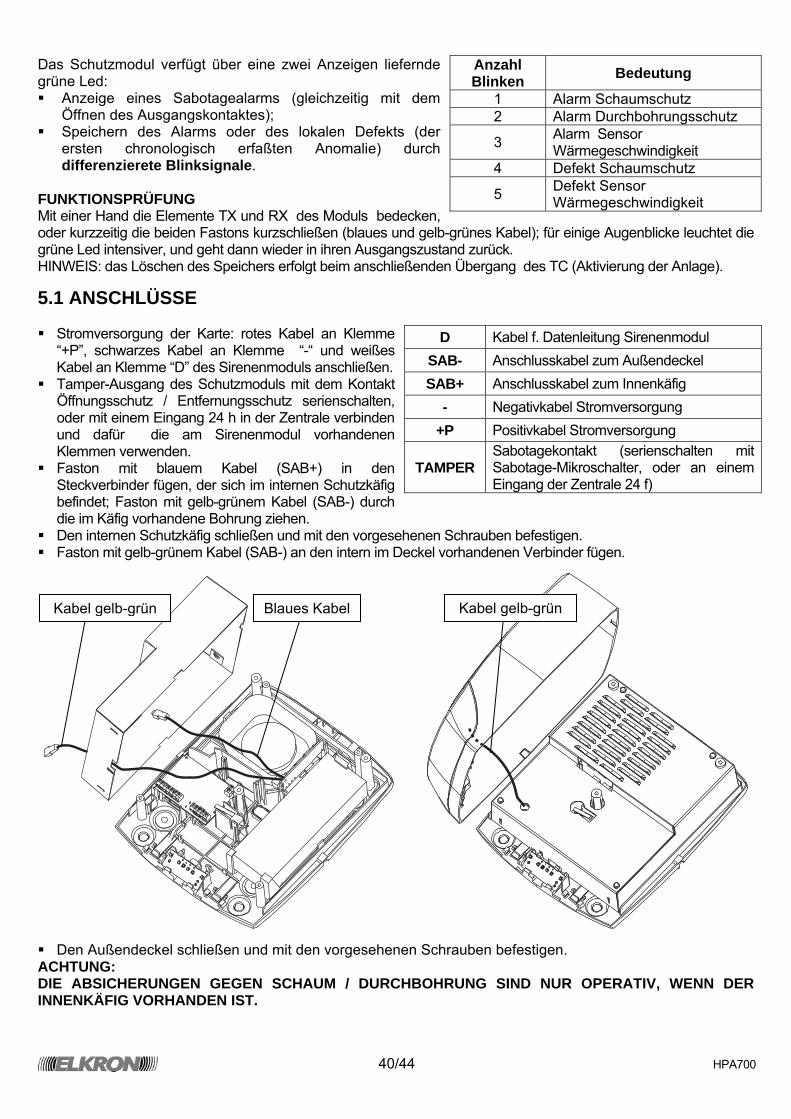
40/44 HPA700
Das Schutzmodul verfügt über eine zwei Anzeigen liefernde grüne Led: Anzeige eines Sabotagealarms (gleichzeitig mit dem
Öffnen des Ausgangskontaktes); Speichern des Alarms oder des lokalen Defekts (der
ersten chronologisch erfaßten Anomalie) durch differenzierete Blinksignale.
FUNKTIONSPRÜFUNG Mit einer Hand die Elemente TX und RX des Moduls bedecken, oder kurzzeitig die beiden Fastons kurzschließen (blaues und gelb-grünes Kabel); für einige Augenblicke leuchtet die grüne Led intensiver, und geht dann wieder in ihren Ausgangszustand zurück. HINWEIS: das Löschen des Speichers erfolgt beim anschließenden Übergang des TC (Aktivierung der Anlage).
5.1 ANSCHLÜSSE Stromversorgung der Karte: rotes Kabel an Klemme
“+P”, schwarzes Kabel an Klemme “-“ und weißes Kabel an Klemme “D” des Sirenenmoduls anschließen.
Tamper-Ausgang des Schutzmoduls mit dem Kontakt Öffnungsschutz / Entfernungsschutz serienschalten, oder mit einem Eingang 24 h in der Zentrale verbinden und dafür die am Sirenenmodul vorhandenen Klemmen verwenden.
Faston mit blauem Kabel (SAB+) in den Steckverbinder fügen, der sich im internen Schutzkäfig befindet; Faston mit gelb-grünem Kabel (SAB-) durch die im Käfig vorhandene Bohrung ziehen.
Den internen Schutzkäfig schließen und mit den vorgesehenen Schrauben befestigen. Faston mit gelb-grünem Kabel (SAB-) an den intern im Deckel vorhandenen Verbinder fügen.
Den Außendeckel schließen und mit den vorgesehenen Schrauben befestigen.
ACHTUNG: DIE ABSICHERUNGEN GEGEN SCHAUM / DURCHBOHRUNG SIND NUR OPERATIV, WENN DER INNENKÄFIG VORHANDEN IST.
Anzahl Blinken Bedeutung
1 Alarm Schaumschutz 2 Alarm Durchbohrungsschutz
3 Alarm Sensor Wärmegeschwindigkeit
4 Defekt Schaumschutz
5 Defekt Sensor Wärmegeschwindigkeit
D Kabel f. Datenleitung Sirenenmodul SAB- Anschlusskabel zum Außendeckel SAB+ Anschlusskabel zum Innenkäfig
- Negativkabel Stromversorgung +P Positivkabel Stromversorgung
TAMPER Sabotagekontakt (serienschalten mit Sabotage-Mikroschalter, oder an einem Eingang der Zentrale 24 f)
Kabel gelb-grün Kabel gelb-grün Blaues Kabel
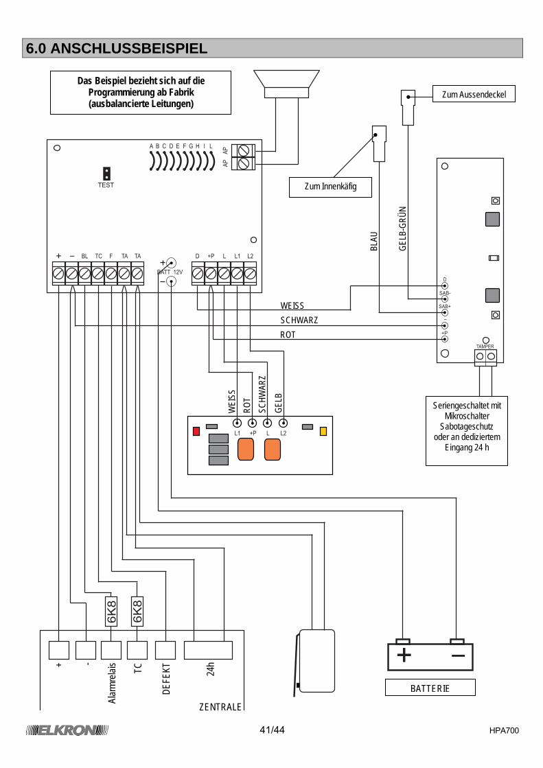
41/44 HPA700
6.0 ANSCHLUSSBEISPIEL
A
AP
AP
TEST
B C D E F G H I L
BATT 12V
+ -
BL TC F TA TA D +P
+P
L
L
L1
L1
L2
L2
D
SAB-
SAB+
-
+P
TAMPER
+ -
6K
8
6K
8
Zum Aussendeckel
Seriengeschaltet mit Mikroschalter
Sabotageschutz oder an dediziertem
Eingang 24 h
BATTERIE
Zum Innenkäfig
WEI
SS
ROT
SCHW
ARZ
GELB
BLAU
GELB
-GRÜ
N
+ -
Alar
mrela
is TC
DEFE
KT 24h
ZENTRALE
WEISS SCHWARZ ROT
Das Beispiel bezieht sich auf die Programmierung ab Fabrik (ausbalancierte Leitungen)
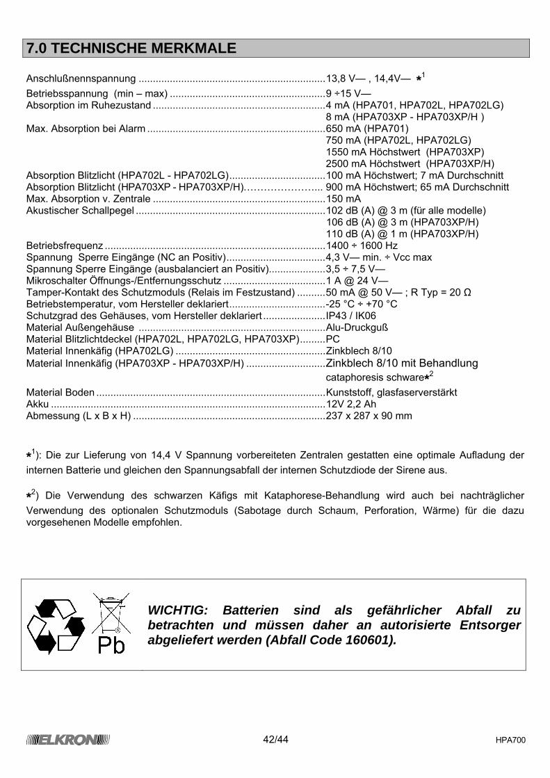
42/44 HPA700
7.0 TECHNISCHE MERKMALE Anschlußnennspannung ..................................................................13,8 V— , 14,4V— *1 Betriebsspannung (min – max) .......................................................9 ÷15 V— Absorption im Ruhezustand .............................................................4 mA (HPA701, HPA702L, HPA702LG) 8 mA (HPA703XP - HPA703XP/H ) Max. Absorption bei Alarm ...............................................................650 mA (HPA701) 750 mA (HPA702L, HPA702LG) 1550 mA Höchstwert (HPA703XP) 2500 mA Höchstwert (HPA703XP/H) Absorption Blitzlicht (HPA702L - HPA702LG)..................................100 mA Höchstwert; 7 mA Durchschnitt Absorption Blitzlicht (HPA703XP - HPA703XP/H)…………………... 900 mA Höchstwert; 65 mA Durchschnitt Max. Absorption v. Zentrale .............................................................150 mA Akustischer Schallpegel ...................................................................102 dB (A) @ 3 m (für alle modelle) 106 dB (A) @ 3 m (HPA703XP/H) .........................................................................................................110 dB (A) @ 1 m (HPA703XP/H) Betriebsfrequenz ..............................................................................1400 ÷ 1600 Hz Spannung Sperre Eingänge (NC an Positiv)...................................4,3 V— min. ÷ Vcc max Spannung Sperre Eingänge (ausbalanciert an Positiv)....................3,5 ÷ 7,5 V— Mikroschalter Öffnungs-/Entfernungsschutz ....................................1 A @ 24 V— Tamper-Kontakt des Schutzmoduls (Relais im Festzustand) ..........50 mA @ 50 V— ; R Typ = 20 Ω Betriebstemperatur, vom Hersteller deklariert..................................-25 °C ÷ +70 °C Schutzgrad des Gehäuses, vom Hersteller deklariert ......................IP43 / IK06 Material Außengehäuse ..................................................................Alu-Druckguß Material Blitzlichtdeckel (HPA702L, HPA702LG, HPA703XP).........PC Material Innenkäfig (HPA702LG) .....................................................Zinkblech 8/10 Material Innenkäfig (HPA703XP - HPA703XP/H) ............................Zinkblech 8/10 mit Behandlung
cataphoresis schware*2 Material Boden .................................................................................Kunststoff, glasfaserverstärkt Akku .................................................................................................12V 2,2 Ah Abmessung (L x B x H) ....................................................................237 x 287 x 90 mm *1): Die zur Lieferung von 14,4 V Spannung vorbereiteten Zentralen gestatten eine optimale Aufladung der internen Batterie und gleichen den Spannungsabfall der internen Schutzdiode der Sirene aus. *2) Die Verwendung des schwarzen Käfigs mit Kataphorese-Behandlung wird auch bei nachträglicher Verwendung des optionalen Schutzmoduls (Sabotage durch Schaum, Perforation, Wärme) für die dazu vorgesehenen Modelle empfohlen.
WICHTIG: Batterien sind als gefährlicher Abfall zu betrachten und müssen daher an autorisierte Entsorger abgeliefert werden (Abfall Code 160601).

43/44 HPA700

44/44 HPA700
ELKRON S.p.A. Via Cimarosa, 39 – 10154 Torino (TO) – ITALY Tel. +39 (0)11.3986711 – Fax +39 (0)11.3986790
www.elkron.com – mail to: [email protected]