KIT RETROFIT cod. CM81414561/0 - CM81414562/0 · 2016-04-08 · KIT RETROFIT cod. CM81414561/0 -...
9
Cod. 71503485/0 ISTR.SOSTITUZIONE TIMER F40...85-BI236-N21S rev.00 KIT RETROFIT cod. CM81414561/0 - CM81414562/0 Composizione Kit 1. Staffetta 2. Timer elettromeccanico 3. cablaggio sostituzione timer Istruzione Smontare il timer AZ Fiber e montare il nuovo timer tramite il fissaggio della staffetta di supporto. Scollegare i fili dal vecchio timer instruction Remove the timer AZ Fiber and fit the new timer with the mounting of the relay support. Disconnect the wires from the old timer
Transcript of KIT RETROFIT cod. CM81414561/0 - CM81414562/0 · 2016-04-08 · KIT RETROFIT cod. CM81414561/0 -...

Cod. 71503485/0 ISTR.SOSTITUZIONE TIMER F40...85-BI236-N21S rev.00
KIT RETROFIT cod. CM81414561/0 - CM81414562/0
Composizione Kit
1. Staffetta
2. Timer elettromeccanico
3. cablaggio sostituzione timer
Istruzione
Smontare il timer AZ Fiber e montare il nuovo timer tramite il fissaggio della staffetta di supporto.
Scollegare i fili dal vecchio timer
instruction
Remove the timer AZ Fiber and fit the new timer with the mounting of the relay support.
Disconnect the wires from the old timer

Cod. 71503485/0 ISTR.SOSTITUZIONE TIMER F40...85-BI236-N21S rev.00
Old timer
Micro
BLUE
BROWN
RED WHITE

Cod. 71503485/0 ISTR.SOSTITUZIONE TIMER F40...85-BI236-N21S rev.00
New Timer

Cod. 71503485/0 ISTR.SOSTITUZIONE TIMER F40...85-BI236-N21S rev.00
La posizione dei fili dei due micro nel nuovo timer hanno la stessa posizione di quello che sostituisce.
Collegare i fili presenti sulla morsettiera del timer AZ tramite il cablaggio dato in dotazione
1. collegare tutti i fili blu chiaro con i fili blu chiaro del kit cablaggio +un filo grigio del timer
2. collegare tutti i fili marroni con i fili marroni del kit cablaggio
3. collegare il filo rosso della macchina con un filo grigio del timer tramite il cavo rosso del kit
cablaggio.
4. collegare tutti i fili bianchi con i fili bianchi del kit cablaggio
5. Se la bobina della valvola solenoide ha due fili neri vanno collegati uno con il blu chiaro e l’altro con
il bianco del kit cablaggio.
6. I fili del kit cablaggio con i fastom maschi non utilizzati vanno rimossi dai morsetti estraibili o isolati.
7. Fascettare i cavi all’interno della macchina per rendere il cablaggio stabile ed evitare il rischio di
contatti accidentali con parti in movimento.
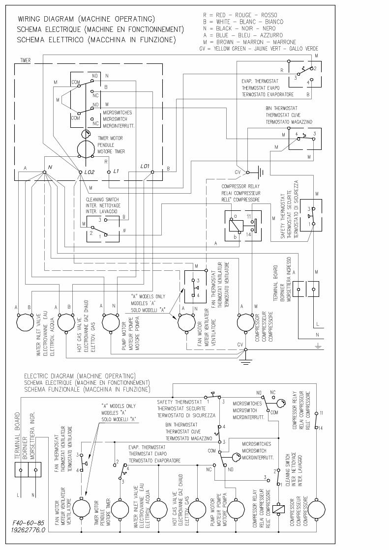
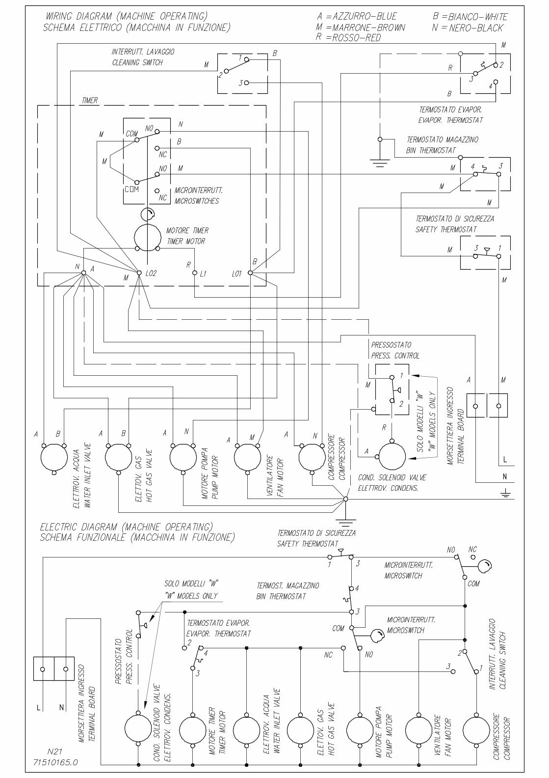
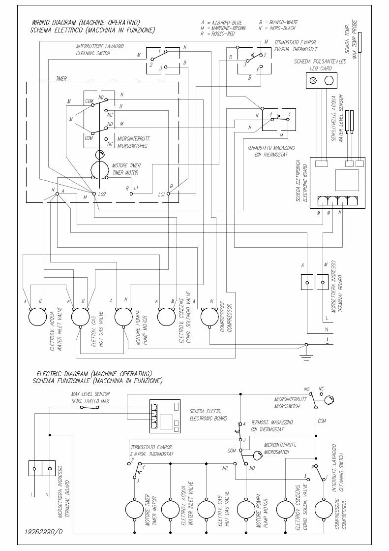
Di seguito vengono allegati gli schemi elettrici
Connect the wires on the terminal board timer AZ by wiring as supplied
1. connect all the wires light blue with light blue wires wiring kit and a gray wire of the timer
2. connect all the wires brown with brown strands of wiring kit
3. connect the red wire of the machine with a gray wire of the timer through red cable of the wiring kit.
Staffetta

Cod. 71503485/0 ISTR.SOSTITUZIONE TIMER F40...85-BI236-N21S rev.00
4. Connect all white wires with the white wires of the wiring kit
5. If the coil of the solenoid valve has two wires than you connect one with the light blue and the other with
the white of the wiring kit.
6. The unused wires of kit must be removed from the plug-in terminals or isolated.
7. Clamp the cables inside the machine to make the wiring stable and avoid the risk of accidental contact
with moving parts.
Below are attached wiring diagrams

CAd6
Font monospazio
N21S A/S
CAd6
Font monospazio
A/W
CAd6
Font monospazio
BI236
CAd6
Nota
Marked impostata da CAd6