
Istruzioni di uso e manutenzioni INOX VFI ONE STEP · GENERALITA’ EN I I riduttori di velocità...
19
GENERALITA’ EN I I riduttori di velocità non ricadono nel campo d’applicazione della Direttiva Macchine 2006/42/CE, in quanto sono identificati come componenti di macchina. L’art. 35 della guida alla Direttiva Macchine stabilisce: "La Direttiva Macchine non si applica direttamente ai componenti delle macchine, quali, per esempio i riduttori di velocità, che non hanno un’applicazione specifica in quanto tali, ma sono destinati ad essere incorporati nelle macchine, sebbene la progettazione e la costruzione di detti componenti devono essere tali da rendere la macchina completata conforme ai requisiti pertinenti e fondamentali in materia di sicurezza e di tutela della salute." Il funzionamento regolare ed il diritto alla richiesta di prestazioni in garanzia richiedono il rispetto delle informazioni contenute nel presente manuale che deve essere letto prima della messa in funzione del gruppo. I Riduttori, che non sono parte integrante di una macchina propriamente definita, non sono quasi macchine, ma sono solo componenti, pertanto non ricadono negli scopi della Direttiva Macchine 2006/42/CE. GENERALITY The gearboxes do not fall within the scope of Machinery Directive 2006/42 / EC, as they are dentified as components of the machine. Article. 35 of the guide to the Machinery Directive states: "The Machinery Directive does not apply directly to the components of the machines, such as, for example, the speed reducers, which does not have a specific application as such, but are intended to be incorporated in machines, although the design and construction of such components must be such as to make the machine completed in compliance with the relevant requirements and basic safety and health protection. " Smooth operation and the right to request under guarantee require compliance with the information contained in this manual, which must be read before starting up the group. The gearboxes, which are not an integral part of a machine properly defined, are not nearly machines, but they are only components, therefore do not fall in the purposes of Machinery Directive 2006/42 / EC.e 2006/42 / EC. USE AND MAINTENANCE / USO E MANUTENZIONE
Transcript of Istruzioni di uso e manutenzioni INOX VFI ONE STEP · GENERALITA’ EN I I riduttori di velocità...

GENERALITA’
EN I
I riduttori di velocità non ricadono nel campo d’applicazione della Direttiva Macchine 2006/42/CE, in quanto sono identificati come componenti di macchina.
L’art. 35 della guida alla Direttiva Macchine stabilisce:"La Direttiva Macchine non si applica direttamente ai componenti delle macchine, quali, per esempio i riduttori di velocità, che non hanno un’applicazione specifica in quanto tali, ma sono destinati ad essere incorporati nelle macchine, sebbene la progettazione e la costruzione di detti componenti devono essere tali da rendere la macchina completata conforme ai requisiti pertinenti e fondamentali in materia di sicurezza e di tutela della salute."
Il funzionamento regolare ed il diritto alla richiesta di prestazioni in garanzia richiedono il rispetto delle informazioni contenute nel presente manuale che deve essere letto prima della messa in funzione del gruppo.
I Riduttori, che non sono parte integrante di una macchina propriamente definita, non sono quasi macchine, ma sono solo componenti, pertanto non ricadono negli scopi della Direttiva Macchine 2006/42/CE.
GENERALITY
The gearboxes do not fall within the scope of Machinery Directive 2006/42 / EC, as they are dentified as components of the machine.
Article. 35 of the guide to the Machinery Directive states:"The Machinery Directive does not apply directly to the components of the machines, such as, for example, the speed reducers, which does not have a specific application as such, but are intended to be incorporated in machines, although the design and construction of such components must be such as to make themachine completed in compliance with the relevant requirements and basic safety and health protection. "
Smooth operation and the right to request under guarantee require compliance with the information contained in this manual, which must be read before starting up the group.
The gearboxes, which are not an integral part of a machine properly defined, are not nearly machines, but they are only components, therefore do not fall in the purposes of Machinery Directive 2006/42 / EC.e 2006/42 / EC.
USE AND MAINTENANCE / USO E MANUTENZIONE

SICUREZZASAFETY
• Written authorization is required to operate or use reducers in man lift or people moving devices.• Check to make sure that certain applications do not exceed the allowable load capacities published in the current catalog.• Buyer shall be solely responsible for determining the adequacy of the product for any and all uses to which Buyer shall apply the product. The application by Buyer shall not be subject to any implied warranty of fitness for a particular purpose.• For safety, Buyer or User should provide protective guards over all shaft extensions and any moving apparatus mounted thereon. The User is responsible for checking all applicablesafety codes in his area and providing suitable guards. Failure to do so may result in bodily injury and/or damage to equipment.• Gearboxes operating in high position should have a protective shield for any possible parts falling down for casual accidents where people are moving under them.• Hot oil and reducers can cause severe burns. Use extreme care when removing lubrication plugs and vents.• Make certain that the power supply is disconnected before attempting to service or remove any components. Lock out the power supply and tag it to prevent unexpected application power.• Reducers are not to be considered fail safe or self-locking devices. If these features are required, a properly sized, independent holding device should be utilized. Reducers should not be used as a brake.• Any brakes that are used in conjunction with a reducer must be sized or positioned in such a way so as to not subject the reducer to loads beyond the catalog rating.• Lifting supports including eyebolts are to be used for vertically lifting the gearbox only and not other associated attachments or motors.• Use of an oil with an EP additive on units with backstops may prevent proper operation of the backstop. Injury to personnel, damage to the reducer or other equipment may result.• Overhung loads subject shaft bearings and shafts to stress which may cause premature bearing failure and or shaft breakage from bending fatigue, it not sized properly.
• E’ richiesta autorizzazione scritta per azionare riduttori in ascensori o dispositivi per il movimento delle persone.• Controllare che alcune applicazioni non eccedano la massima capacità di carico ammessa pubblicata in questo catalogo.• L’acquirente è l’unico responsabile per la determinazione dell’adeguatezza del prodotto per qualcuna o tutte le utilizzazioni che l’acquirente stesso farà del riduttore. L’applicazione dell’acquirente non potrà essere soggetta ad alcuna implicitagaranzia di montaggio per uno scopo particolare.• Per ragioni di sicurezza l’acquirente dovrà provvedere a porre protezioni adeguate su tutta la lunghezza dell’albero a tutti gli organi in movimento. L’utilizzatore è responsabile del controllo di tutti i codici di sicurezza e la predisposizione di protezioni adeguate. In assenza di tali precauzioni si possono verificare incidenti alle persone e danni agli apparati.• Su riduttori installati in posizioni elevate utilizzare protezioni adeguate per qualsiasi distacco accidentale di parti nel caso di passaggio di persone al di sotto. • Olio e riduttori bollenti possono causare gravi ustioni. Usare estrema cautela nella rimozione dei tappi e delle ventole.• Assicurarsi che la corrente di alimentazione sia scollegata prima di riparare o rimuovere alcun componente. Chiudere l’alimentazione e contrassegnare tale operazione per evitare accensioni accidentali.• I riduttori non devono essere considerati esenti da guasti o a bloccaggio automatico. Se sono indispensabili queste caratteristiche, deve essere utilizzato un dispositivo indipendente della dimensione adatta.I riduttori non devono essere utilizzati come freni.• Qualsiasi freno sia utilizzato insieme al riduttore deve essere della giusta grandezza e posizionato in modo da non causare carichi eccessivi non previsti dai dati forniti nel catalogo.• I dispositivi di sollevamento come le golfare devono essere usati solo per sollevare verticalmente il riduttore e non altri di spositivi associati o motori.• L’utilizzo di un olio con un additivo EP su gruppi provvisti di dispositivo di arresto possono inficiare l’uso corretto del freno e provocare danni alle persone, alle cose ed al riduttore stesso nonché ad altri apparecchi.• I Carichi sospesi assoggettano i cuscinetti della vite e la vite stessa a sollecitazioni che possono causare, se non adeguatamente dimensionati, l’usura prematura dei cuscinetti e/o la rottura della vite a causa della resistenza alla flessione.
EN I
USE AND MAINTENANCE / USO E MANUTENZIONE

SICUREZZA
I riduttori presenti in questo manuale sono rivolti ad uso in applicazioni industriali e corrispondono agli standard e alle regolamentazioni adottabili.
Le prestazioni e i dati tecnici sono rintracciabili sulla targhetta e sulla relativa documentazione .
TrasportoVerificare con attenzione lo stato al ricevimento e contestare immediatamente eventuali danni al trasportatore.
ASSEMBLAGGIO DEI PRODOTTI
I seguenti disegni di assieme hanno come fine di aiutare nella ricerca dei componenti principali dei vari tipi diriduttore.Le varie forme costruttive e dimensionali, delle versioni di montaggio, del numero di coppie di riduzione, generano in realtà molteplici soluzioni e pertanto si invita a richiedere la documentazione specifica.
Gearboxes in this manual are intended for use in industrial applications and meet the standards and regulations that can be adopted.
The performance and specifications are traceable on the nameplate and related documentation.
TransportCarefully check the status upon receipt and any damage immediately to the carrier.
ASSEMBLY OF PRODUCTS
The following assembly drawings are meant to assist in the search of the main components of the various types of gearbox.
The various designs and dimensions, assembling versions, number of stages, actually generate multiple solutions and therefore we invite you to apply for specific documentation.
EN I
SAFETY
USE AND MAINTENANCE / USO E MANUTENZIONE

2RS2RS
V6V5
d D
d
d > D
Please Check
Do not change mounting positions withoutcontacting our factory. Altering the mountingposition may require special lubrication pro-visions which must be installed from thefactory. When reducers are mounted in posi-tions V5 or V6 and used in continuous dutyapplications, replace the upper bearing witha self lubricated style bearing.
Specificare in fase d’ordine se i riduttoridevono essere forniti per posizioni di mon-taggio V5÷V6 per prevedere eventualicuscinetti 2RS (schermati), ed eventualianelli di tenuta aggiuntivi.
L’accoppiamento al motore deve essere li-bero e scorrevole. Il serraggio delle viti di fis-saggio deve essere effettuato solo quando ledue flange saranno a contatto.Ad assemblaggio avvenuto controllare che ilmotore ruoti liberamente agendo manual-mente sulla ventola.
When mounting a motor to reducers, thefastening bolts should not be tightened un tilboth the reducer flange and motor face arein contact. When mounting is completecheck by manually rotating the fan to besure the assembly turns freely.
Make sure that munting of pulleys or pinionsdoes not create over hung loads exceedingthe capacity of the reducer.
When mounting pinions, pulleys or couplingson the reducer’s shaft, protect the bearingsfrom impact by using the appropriate pullersand threaded holes in the end of the reducershaft.
Nel montaggio di pignoni, giunti o puleggesugli alberi del riduttore evitare urti facendouso di appropriati estrattori ancorati nei forifilettati presenti all’estremità degli alberistessi.
Accertarsi che l’eventuale montaggio di pi-gnoni o pulegge a sbalzo su gli alberi sia sta-to convalidato da precedenti verifiche diammissibilità dei carichi risultanti.
When mounting items to the reducer shaft,appropriate anti-seize and oxidizer com -pounds should be used, and keys dimen -sions are correct.
In tutti gli accoppiamenti albero/mozzo spal-mare le superfici a contatto con adeguatiprotettivi antiossi dazione e verificare che lelinguette non siano forzate onde evitare larottura del mozzo.
> D
InstallazioneInstallation
Lasciare fra il copriventola del motore el’eventuale parete uno spazio sufficiente a garantire il passaggio dell'aria di raffredda-mento.
Make sure there is sufficient space betweenany obstructions and the motor’s air intakearea to provide adequate cooling for the mo-tor.
In applicazioni con un carico radiale moltoelevato si consiglia di prevedere un supportosupplementare sull’albero.
For very heavy radial load, additional outputshaft support may be required to preventpremature bearing failure or shaft breakagefrom bending fatigue.
EN I
INSTALLATION CHECK LIST

CAUTION
CAUTION
A
MountingPositions
Factors
Amperage
CHECK!
Service
The system of connected rotating parts mustbe free from critical speed, torsional or othertype vibration, no matter how induced. Theresponsibility for this system ananlysis lieswith the purchaser of the speed reducer.
Check shaft and coupling alignment. Checkproper coupling gap before to lock all foun-dation bolts that should be routinely checked.
For safety, Buyer or User should provideprotective guards over all shaft extensionsand any moving apparatus mountedthereon. The User is responsible forchecking all applicable safety codes in hisarea and providing suitable guards. Failureto do so may result in bodily injury and/ordamage to equipment.
Per la sicurezza, il compratore o l'utente do-vrebbero prevedere delle protezioni sopratutti gli alberi e tutti gli apparecchi messi inrotazione montati sul riduttore.
Si consiglia di controllare l’allineamento delleparti in rotazione (collegamenti, alberi etc.)prima della messa in funzione del riduttore eperiodicamente controllare il fissaggio deibulloni di collegamento.
Il collegamento delle parti in rotazione deveessere esente da qualsiasi tipo di torsione odi vibrazione dovuta alla velocità.
Test run the first unit to verify proper opera-tion.
Si consiglia di eseguire un chek-up di provaprima della messa in funzione per assicurareun funzionamento adeguato, controllando laPotenza Assorbita.
Please Check
In applicazioni caratterizzate da numerosiavviamenti/arresti o inversioni, è consigliabi -le bloccare le viti di fissaggio delle flange.
In applications where multiple starts, stopsor reverses occurs, it is recommended toblock the fastening bolts of the output flangeand feet.
Assembled with glueMontare con bloccante
EN I
INSTALLATION CHECK LIST
!
!

Condizioni di fornituraSupply terms
ManutenzioneMainteinance Gearboxes that are lubricated for life do not
require any mainteinance.For others, the lubricant needs to be perio-dically refilled and eventually changed witha suitable grade.
Avoid mixing synthetic and mineral lubricants.
It is advisable to carry out the first mineral oilchange after 150 operating hours and thesubsequent ones every 4000 operatinghours.
From time to time check that the fan cowl isnot clogged with dust or fibres.
For brake motors it is also necessary to pe-riodically check the air gap and replace thebrake lining if the values exceed permissibleones.Also check the brake torque using a torquemeter.
I riduttori lubrificati a vita non necessitano dimanutenzione. Per gli altri è necessario effettuare una verifica periodica del livello del l'olio eventualmente ripristinandolo con un tipo compatibile.
Evitare di mescolare olii sintetici con olii mi-nerali.
Effettuare il primo cambio del l'olio mine-rale dopo 150 ore e i successivi dopo 4000ore di funzionamento.Verificare che la griglia posteriore del motorenon sia ostruita da polvere, filamenti o altro.
Nei motori autofrenanti controllareperiodicamente il valore del traferroeffettuando la sostituzione del ferodo se i valori sono superiori a quelli ammessi.Verifi care la coppia frenante con chiavedinamometrica.
Gearboxes are supplied as follows:• prearranged to be installed in the ordered mounting position• tested as per internal specifications• with appropriate packing• coupling surfaces not painted• without nuts and bolts for motor mounting as per IEC version• already filled in with lubricant where speci- fied• already painted where specified• already equipped with lifting eyebolts
I riduttori vengono forniti come segue:• già prediisposti per essere installati nella posizione di montaggio come definito in fase di ordine• collaudati secondo specifiche interne• appositamente imballati• le superfici di accoppiamento non sono verniciate• sprovvisti di dadi e bulloni per montaggio motori per la versione IEC• già provvisti di lubrificante (dove previsto)• già verniciati (dove previsto)• già provvisti di golfare di sollevamento (dove previsto)
EN I
INSTALLATION / INSTALLAZIONE

Alle tabelle di selezione dei riduttori è asso -ciata la seguente simbologia:
Following symbols will be found in the selec-tion tables of the gearboxes:
-1 -1n [min ] output speed (n = 1400 min )2 1
i — reduction ratio
-1P [kW] motor input power (n = 1400 min )1M 1
-1M [Nm] output torque (n = 1400 min )2M 1
P [kW] Transmitted power at input gearbox1R
M [Nm] Transmitted output torque2R
RD — Dynamic efficiency
Mn — Tooth normal module
-1 -1n [min ] giri in uscita (n = 1400 min )2 1
i — rapporto di riduzione
-1P [kW] potenza nominale motore (n = 1400 min )1M 1
-1M [Nm] coppia in uscita (n = 1400 min )2M 1
P [kW] potenza trasmessa in entrata1R
M [Nm] coppia trasmessa in uscita2R
RD — rendimento dinamico
Mn — modulo normale del dente
-1n = 1400 min1
-1n = 2800 min1
-1n = 900 min1
P ≥ P x fs1R 1r
P x 1.6 ≥ P x fs1R 1r
Where 2 pole motors are required, specify when placingorder to foresee lubricant and synthetic oil.
-1Per l'abbinamento a motori a 2800 min , specificaresempre tale caratteristica in fase di ordine per prevederelubrificante e olio sintetico.
P / 1.5 ≥ P x fs1R 1r
A gear box version B is to be found fromthe selection tables, considering the re-quired power P (or torque M required) and1r 2r
-1output speed n referred to 1400 min (or to2
gearbox ratio).Once the gearbox has been chosen, P1R
power and n speed (given in the table), it1
should comply with the following conditions:
Gearbox selectionScelta di un riduttore
Un riduttore nella configurazione B dovràessere ricercato nelle tabelle di selezio-ne riduttori in base alla potenza richiesta P1r
(o alla coppia richiesta M ) e ai giri uscita n2r 2-1riferiti a 1400 min ( o al rapporto di trasmis-
sione i).Il riduttore selezionato in base alla potenzaP (indicata in tabella) e a n dovrà soddi-1R 1
sfare le seguenti condizioni:
N.B. Per azionamenti con motore a scoppio o per funzio -namento alternato istantaneo, moltiplicare il valore delcoefficiente di servizio per 1.15.
N.B. For applications with flameproof motors or instanta -neous reversal, multiply the service coefficient by 1.15.
Service factorFattore di servizio
1
fs
Tipo di carico e avviamenti per oraType of load and starts per hour Ore di funz. giorn.
Oper. hours per day
<2 h 2 - 8 h 8 - 16 h
Applicazione cont. o interm. con n.ro operazioni/oraContinuous or intermittent appl. with start/hour
≤ 10
Uniform / Uniforme 0.9 1 1.25
Moderate / Moderato 1 1.25 1.5
Heavy / Forte 1.25 1.5 1.75
Applicazione intermittente con n.ro operazioni/oraIntermittent application with start/hour
> 10
Uniform / Uniforme 1.25 1.5 1.75
Moderate / Moderato 1.5 1.75 2
Heavy / Forte 1.75 2 2.25
20 Nm
200
132
93
74
47
10.6 10
13
16
15
2.3
P Mnf.s.
i
1.6
1.3
1.3
1.1
7 70.18
0.18
0.18
0.18
0.12
15
19
30
1M-1
2M2
[min ] [kW] [kW][Nm] [Nm]
2
Per una corretta selezione del riduttore omotoriduttore è importante rispettare le se-guenti indicazioni:
For a proper selection of the required gear-box it is important to follow the followingtable:
Determinare tramite la seguente tabella ilfattore di servizio fs relativo all'applicazione.
Find out the application service factor thro-ugh the following table.
2 Poli2 Poles
6 Poli6 Poles
0.42
0.28
0.24
0.20
0.16
16
16
18
18
20
P M1R 2R
N.B.
N.B.
IEN
SELECTION GUIDE / GUIDA ALLA SELEZIONE
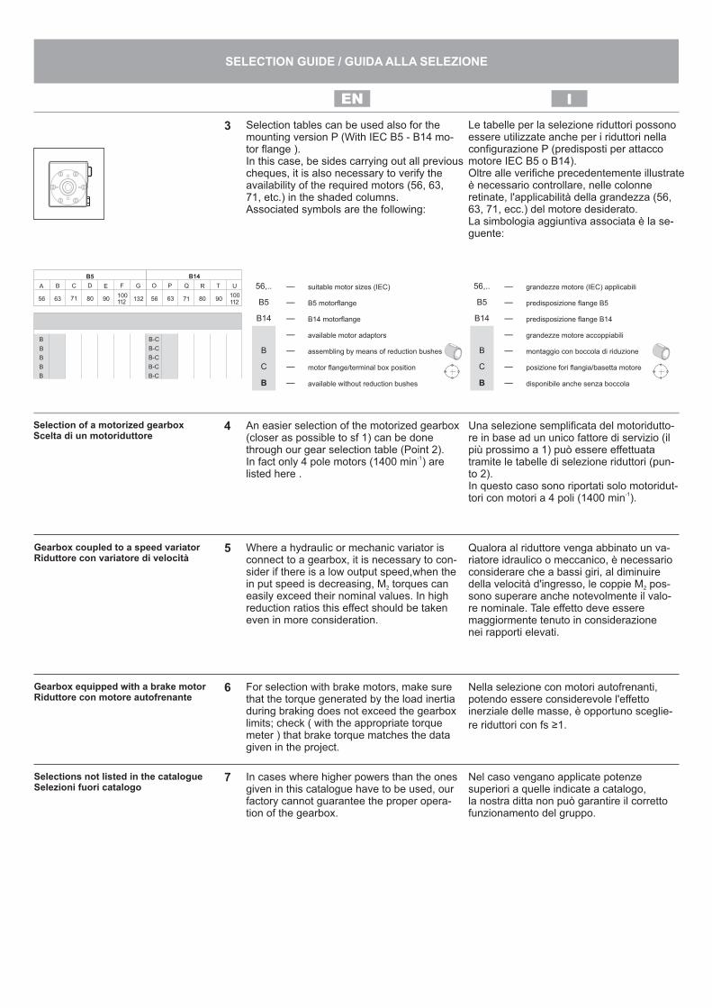
Selection tables can be used also for themounting version P (With IEC B5 - B14 mo-tor flange ).In this case, be sides carrying out all previouscheques, it is also necessary to verify theavailability of the required motors (56, 63,71, etc.) in the shaded columns.Associated symbols are the following:
Le tabelle per la selezione riduttori possonoessere utilizzate anche per i riduttori nellaconfigurazione P (predisposti per attaccomotore IEC B5 o B14).Oltre alle verifiche precedentemente illustrateè necessario controllare, nelle colonneretinate, l'applicabilità della grandezza (56,63, 71, ecc.) del motore desiderato.La simbologia aggiuntiva associata è la se-guente:
B5
A
56 5663 6371 7180 8090 90100 100112 112
132
B
B
B
B
B
B
B-C
B-C
B-C
B-C
B-C
C D E F G O P Q R T U
B14
3
56,.. — grandezze motore (IEC) applicabili
B5 — predisposizione flange B5
B14 — predisposizione flange B14
— grandezze motore accoppiabili
B — montaggio con boccola di riduzione
C — posizione fori flangia/basetta motore
B — disponibile anche senza boccola
56,.. — suitable motor sizes (IEC)
B5 — B5 motorflange
B14 — B14 motorflange
— available motor adaptors
B — assembling by means of reduction bushes
C — motor flange/terminal box position
B — available without reduction bushes
5
6
7
Una selezione semplificata del motoridutto-re in base ad un unico fattore di servizio (ilpiù prossimo a 1) può essere effettuatatramite le tabelle di selezione riduttori (pun-to 2).In questo caso sono riportati solo motoridut-
-1tori con motori a 4 poli (1400 min ).
An easier selection of the motorized gearbox(closer as possible to sf 1) can be donethrough our gear selection table (Point 2).
-1In fact only 4 pole motors (1400 min ) arelisted here .
Gearbox coupled to a speed variatorRiduttore con variatore di velocità
Qualora al riduttore venga abbinato un va-riatore idraulico o meccanico, è necessarioconsiderare che a bassi giri, al diminuiredella velocità d'ingresso, le coppie M pos-2
sono superare anche notevolmente il valo-re nominale. Tale effetto deve esseremaggiormente tenuto in considerazionenei rapporti elevati.
Where a hydraulic or mechanic variator isconnect to a gearbox, it is necessary to con-sider if there is a low output speed,when thein put speed is decreasing, M torques can2
easily exceed their nominal values. In highreduction ratios this effect should be takeneven in more consideration.
Gearbox equipped with a brake motorRiduttore con motore autofrenante
For selection with brake motors, make surethat the torque generated by the load inertiaduring braking does not exceed the gearboxlimits; check ( with the appropriate torquemeter ) that brake torque matches the datagiven in the project.
Nella selezione con motori autofrenanti,potendo essere considerevole l'effettoinerziale delle masse, è opportuno sceglie-
re riduttori con fs ≥1.
Selections not listed in the catalogueSelezioni fuori catalogo
In cases where higher powers than the onesgiven in this catalogue have to be used, ourfactory cannot guarantee the proper opera-tion of the gearbox.
Nel caso vengano applicate potenzesuperiori a quelle indicate a catalogo,la nostra ditta non può garantire il correttofunzionamento del gruppo.
Selection of a motorized gearboxScelta di un motoriduttore
4
IEN
SELECTION GUIDE / GUIDA ALLA SELEZIONE
8NotesNote
It is necessary to refer the following the appli-cations to our technical service.— Applications where gearbox failure is critical.— Applications with particularly high inertias— Lifting devices.— High dynamic stress on gearbox housing.— Particular environment conditions with temperatures lower than 5°C or higher than 40°C.— Highly chemical aggressive environment.— Salty environment.— Applications not considered in the cata- logue.— Radioactive environment.— Pressure different to atmospheric.— Avoid those applications where total or partial immersion of the gearbox is required.
Occorre tenere nella giusta considerazionee valutare attentamente le segg. applicazioniconsultando il ns. Servizio Tecnico.— Utilizzo in servizi che potrebbero risulta- re pericolosi per l’uomo in caso di rottura del riduttore.— Applicazioni con inerzie particolarmente elevate.— Utilizzo come organo di sollevamento.— Applicazioni con elevate sollecitazioni di- namiche sulla cassa del riduttore.— Utilizzo in ambiente con temperatura in- feriore a 5°C o superiore a 40°C.— Utilizzo in ambiente con presenza di ag- gressivi chimici.— Utilizzo in ambiente salmastro.— Posizioni di piazzamento non previste a catalogo.— Utilizzo in ambiente radioattivo.— Utilizzo in ambiente con pressione diver- sa da quella atmosferica.— Evitare applicazioni dove è prevista l’immersione, anche parziale, del ridutto- re.
IEN
SELECTION GUIDE / GUIDA ALLA SELEZIONE

60
100
80
1 Time (h)
B
100% Power
C
D
0
20
40C°
1 Time (h)
0/80% of Power
A
I riduttori a vite senza fine, dato lo schemacostruttivo, trasformano parte della potenzainstallata in calore che viene smaltito dallacarcassa e in corrispondenza della vite senzafine può raggiungere valori misurati nell’intornodi 80 - 100 °C senza che questo pregiudichi lameccanica del riduttore.Il diagramma dell'incremento della temperaturein funzione del tempo di funzionamento èillustrato nel grafico A.La temperatura finale raggiunta è data dallasomma di varie componenti:- Potenza installata e percentuale di utilizzo- Temperatura ambiente- Tipo di lubrificazione- Tipo di raffreddamento- Velocità in ingresso
In questo caso la curva di aumento tempe-ratura è simile a quella del funzionamentocontinuo e normalmente viene raggiunto ilvalore massimo in 20/30 minuti circa e con il100% del la potenza utilizzata.In qualsiasi punto di tale curva venga quindia fermarsi il riduttore, si crea una curva di raf-freddamento che è più o meno rapida a se-conda della temperatura ambiente (graficoB).
Se il riduttore ha poi cicli di arresti ed avvia-menti, la temperatura finale dipende dal tem-po di arresto e difunzionamento (con uncomportamento molto simile a quello dei mo-tori elettrici con funzionamento S3 o S6, vedigrafici C e D).I valori del fattore di servizio fs=1 riportati inquesto catalogo si riferiscono ad un tipo difunzionamento intermittente.
La selezione di motorizzazioni con velo-cità in entrata a 2800 min-1 è ammessa per applicazioni intermittenti, dato l'elevato aumento della temperatura di funzionamento derivante dalla elevatavelocità di rotazione.In questo caso interpellare il nostro Ser-vizio tecnico Commerciale.
Worm gearboxes, because of their inside de-sign, transform part of their installed powerinto heat which is subsequently disposed ofthroughout the housing and may result intovalues, measured onto the gear case in thearea of the worm shaft, in the range of 80 -100 °C without this affecting the operationof the gear unit adversely.The diagram of the temperature increasedepending on the operating time isillustrated in graph A. Final temperature isgiven by the sum of several components :- Installed power and percentage of usage- Ambient temperature- Lubrication- Cooling method- Input speed
In this case the temperature increase curveis similar to the one for continuous duty. Infact the peak is reached in approximately20/30 min utes using 100% of the power.
The gearbox can be stopped at any point ofthis curve then following a cooling curvewhose shape depends on the ambient tem-perature (graph B).
Should the gearbox have several starts andstops cycles, the final temperature dependson starts and stops times (very similar toelectric motors with operation S3 and S6see graphs C and D).Service factor values indicated in this cata-logue refer to an intermittent duty.
Geared motor selections with 2800 min-1input speed are tolerated for intermittentduty applications only, because of thehigh temperature in crease resulting fromthe input rotation speed.For these cases please contact technicaldepartment.
Thermal limit with intermittant dutyLimite termico per funzionamentointermittente
Thermal limitLimite termico
T1 T T1T
100% of Power
50% of Power 50% of Power
100% Power SF=1
60
100
80
0
20
40C°
60
100
80
0
20
40C°
1 Time (h)
Time (h)
60
100
80
0
20
40C°
1
I
THERMAL LIMIT / LIMITE TERMICO
EN

53
I30 I45 I50 I63 I11
i
>25° 7 7 7
12° - 25°
5
1015
1014
710
1015
10162023
8° - 12° 20 211418
1924
5° - 8° 30 282636
3036
303845
64
3° - 5° 40374660
436068
456780
8499
1° - 3°6180
70102
80100
94
>25° Reversibilità totaleTotally reversible
12° - 25°Staticamente reversibileRitorno rapidoDinamicamente reversibile
Statically reversibleQuick returnDynamically reversible
8° - 12°Irreversibilità statica incertaRitorno rapido in caso di vibrazioni Dinamicamente reversibile
Variable static non-reversingQuick return in case of vibrationsDynamically reversible
5° - 8°Staticamente irreversibileRitorno in caso di vibrazioniCattiva reversibilità dinamica
Statically non-reversingReturn in case of vibrationsBad dynamic reversing
3° - 5°Staticamente irreversibileRitorno a scatti lenti in caso di vibrazioniReversibilità dinamica quasi nulla*
Statically non-reversingSlow movement return in case of vibrationsLow dynamic reversing*
1° - 3°Staticamente irreversibileNessun ritornoReversibilità dinamica quasi nulla*
Statically non-reversingNo returnLow dynamic reversing*
* Ci teniamo ad evidenziare che l'irreversi-bilità totale non può essere garantitapertanto, dove essa è richiesta, è neces-sario predisporre di un sistema di frena-tura esterno al riduttore.
IrreversibilityIrreversibilità
7
* We would like to draw your attention onthe fact that the total irreversibility can-not be guaranteed, therefore, where it isrequired, it is recommended to arrangean external braking device.
Nei riduttori a vite senza fine è importantetenere in considerazione i vari gradi di re-versibilità (o irreversibilità) della coppia vi-te-corona, per garantire una correttaselezione nelle applicazioni dove questeesigenze sono determinanti al fine del buonfunzionamento dell'impianto.La tabella seguente riporta i vari gradi di re-versibilità nei riduttori a vite senza fine de fi-niti in base all'angolo d'elica ß e al rapportodi riduzione i.
With wormgear boxes it is always importantto consider the several levels of reversibility(or irreversibility) of the worm gear set, in or-der to guarantee a correct selection in appli-cations where these requirements areessential for the operation of the machine.The following table shows the different ta-bles of reversibility for worm gearboxesaccording to helix angle ß and reductionratio i.
I85
7
10142022
28384652
677496
I
IRREVERSIBILITY / IRREVERSIBILITA’
EN

I riduttori tipo I30÷I11 sono forniti con lubrificazione permanente a olio sintetico per le posizioni di montaggio B3-B6-B7-B8 e non richiedono alcuna manutenzione.
Per le posizioni di montaggio V5-V6 contattare la nostra ditta.
Units I30 to I11 are supplied with synthetic oil, providing "long life" lubrication, for mounting positions B3-B6-B7-B8 and maintenance is not necessary.
For V5-V6 please contact us.
STAINLESSTEEL WORM GEARBOXES VFI
STAINLESSTEEL RIDUTTORI A VITE SENZA FINE VFI
Q.tà
I30÷I11 I45 I50 I63 I110.10 Lt 0.24 Lt 0.38 Lt 0.98 / 0.69 Lt 3.50 / 1.60 Lt
I30 I852.10 / 1.50 Lt
AGIP SHELLTellium VSF 320 Omala S4 WE 320
LUBRICATION / LUBRIFICAZIONE
IEN
I

On
req
uest
/ A
ric
hie
sta
Sta
nd
ard
V6
B6
B3
B8
B7
V5
5
5
5
5
5
5
data 17/03/15LUB_VFI_01
These plugs are on the back side. Filling & Breather Filling closed Emptying Level
DescriptionSynthetic food oil ‘Foodlube 320'Synthetic food oil ‘Mobil DTE 320'Synthetic food oil ‘Foodlube 150'Synthetic food oil ‘Mobil DTE 150'
Code
LUOFOOD320
LUOFOOD150
FOOD OIL
Type I300.10
F
I450.24
G
I500.38
H
I630.98
H
I852.10
H5
Type I300.10
F
I450.24
G
I500.38
H
I630.69
H
I851.50
H5
Type I300.10
F
I450.24
G
I500.38
H
I630.69
H
I851.50
H5
Type I300.10
F
I450.24
G
I500.38
H
I630.98
H
I852.10
H5
Type I300.10
F
I450.24
G
I500.38
H
I630.98
H
I852.10
H5
Type I300.10
F
I450.24
G
I500.38
H
I630.98
H
I852.10
H5
I113.50
H
I112.50
H
I112.50
H
I112.10
H
I111.60
H
I111.60
H
TO3/8SCIORInox plug cl.+OR 3/8
TO1/8SCIORInox plug cl.+OR 1/8
TO1/4SCIORInox plug cl.+OR 1/4
Oil q.ty (Lt.)
Std. oil plug
Oil q.ty (Lt.)
Oil q.ty (Lt.)
Oil q.ty (Lt.)
Oil q.ty (Lt.)
Oil q.ty (Lt.)
Std. oil plug
Std. oil plug
Std. oil plug
Std. oil plug
Std. oil plug
OIL PLUG POSITIONS - TYPES / POSIZIONE TAPPI OLIO - TIPI
H
F
G
03
04
1..
VT
BIM
06
*14
Lo
cke
d s
cre
ws w
ith
LO
CT
ITE
35
A4
2
CS
S6
19
04
or
61
90
4/2
Z f
or
CS
SV
5
SG
/J4
7
CS
S1
60
05
CS
S1
60
05
62
01
/2R
SC
SM
SG
/J3
2
SG
AS
12
AT
CA
00
0*0
32
*07
Lo
cke
d R
CA
plu
g w
ith
LO
CT
ITE
49
5
I30
88
00
Fro
m_______________________________ D
ate
___ / _
__ / _
_______
Description
Ord
er
form
part
s r
equired fro
m g
earb
ox s
ize
ratio _
________
I30
Part
sQ
.ty
��
Fa
x:
+3
9 0
44
4 5
36
13
9 -
e-m
ail:
hyd
rom
ec@
hyd
rom
ec.c
om
AT
BA
02
0*0
37
*07
C
AT
BL
02
5*0
47
*07
V
AT
BL
02
5*0
40
*07
V
I45
90
11
FL
VT
EIM
06
*16
AT
BA
02
0*0
30
*07
Ad
d o
il se
als
on
th
em
oto
r fla
ng
e o
nly
for
AT
EX
**M
oto
r fixin
g s
cre
ws
n°4
M5
x1
6T.E
. In
ox
n°4
M5
x1
6T.E
. In
ox
IEC
56
B1
46
3 B
14
Co
de
I30
.4.0
46
I30
.4.0
45
**
ø1
4M
etr
ic I
03
00
1..
.In
ch
UI0
30
01
...
(ø1
5.8
75
mm
)ø
5/8
"
OR
S3
4.6
5*1
.78
TO
1/8
SC
IOR
Lo
cke
d o
il p
lug
with
LO
CT
ITE
35
A4
2
TP
7.2
*6.5
TP
5.1
*6.0
Sta
inle
sste
el
Wo
rmg
ea
rbo
x
MO
UN
TIN
G P
OS
ITIO
NS
B3
B8
B6
B7
V5
V6
FC
/FL
SP
AR
EP
AR
TS
/P
AR
TID
IR
ICA
MB
IOd
ata
1
7/0
3/1
5
VF
I_I3
0/0
1
OIL
Q.T
Y/
Q.T
A’O
LIO
I3
0-E
XP
/01
0.1
0 L
t.

Fro
m_______________________________ D
ate
___ / _
__ / _
_______
Description
Ord
er
form
part
s r
equired fro
m g
earb
ox s
ize
ratio _
________
I45
Part
sQ
.ty
��
Fa
x:
+3
9 0
44
4 5
36
13
9 -
e-m
ail:
hyd
rom
ec@
hyd
rom
ec.c
om
I45
90
11
FL
VT
EIM
06
*16
TO
1/4
SC
IOR
Lo
cke
d o
il p
lug
with
LO
CT
ITE
35
A4
2TP
7.2
*6.5
OR
S4
7.0
0/2
.00
TP
5.1
*6.0
SG
/J4
7
AT
BL
03
0*0
47
*07
V
VT
BIM
06
*14
Lo
cke
d a
ll scre
ws
with
LO
CT
ITE
35
A4
2
VT
SIM
06
*12
IL
ocke
d a
ll scre
ws
with
LO
CT
ITE
35
A4
2
AT
BL
03
0*0
47
*07
V
CS
S6
00
6
CS
S6
00
6C
SM
62
02
/2R
S
SG
/J3
5
AT
CA
00
0*0
35
*07
Lo
cke
d R
CA
plu
g w
ith
LO
CT
ITE
49
5
AT
BA
02
5*0
40
*07
VA
dd
oil
se
als
on
th
em
oto
r fla
ng
e o
nly
for
AT
EX
AT
BA
02
5*0
40
*07
C
**M
oto
r fixin
g s
cre
ws
n°4
M5
x1
6T.E
. In
ox
n°4
M6
x2
0T.E
. In
ox
n°4
3/8
-16
x1
.00
T.E
. In
ox
Mo
t.6
3 B
14
71
B1
45
6C
Co
de
I50
.4.0
47
I50
.4.0
45
UI5
04
04
1
**
CS
M6
00
5 o
r6
00
5/2
Z f
or
CS
MV
5
04
54
1..
ø1
8M
etr
ic I
04
50
1..
.In
ch
UI0
45
01
...
(ø1
9.0
5m
m)
ø3
/4"
I45
88
00
I45
90
20
OR
S7
2.7
5/1
.78
OR
S11
8/2
.62
on
lyfo
rU
I50
40
41
Sta
inle
sste
el
Wo
rmg
ea
rbo
x
MO
UN
TIN
G P
OS
ITIO
NS
B3
B8
B6
B7
V5
V6
FC
/FL
SP
AR
EP
AR
TS
/P
AR
TID
IR
ICA
MB
IOd
ata
1
7/0
3/1
5
VF
I_I4
5/0
1
OIL
Q.T
Y/
Q.T
A’O
LIO
I4
5-E
XP
/01
0.2
4 L
t.
Fro
m_______________________________ D
ate
___ / _
__ / _
_______
Description
Ord
er
form
part
s r
equired fro
m g
earb
ox s
ize
ratio _
________
I50
Part
sQ
.ty
��
Fa
x:
+3
9 0
44
4 5
36
13
9 -
e-m
ail:
hyd
rom
ec@
hyd
rom
ec.c
om
0.3
8 L
t.
I50
90
11
FL
VT
EIM
06
*14
TO
3/8
SC
IOR
Lo
cke
d o
il p
lug
with
LO
CT
ITE
35
A4
2
TO
7.2
*6.5
TO
5.1
*6.0
OR
S4
7.0
0/2
.00
OR
S8
2.2
8/1
.78
AT
BL
04
0*0
55
*07
V
VT
BIM
06
*14
Lo
cke
d a
ll scre
ws
with
LO
CT
ITE
35
A4
2
VT
SIM
06
*12
IL
ocke
d a
ll scre
ws
with
LO
CT
ITE
35
A4
2
AT
BL
04
0*0
55
*07
V
CS
S6
00
8
CS
S6
00
8
CS
M6
20
4/2
RS
SG
AS
20
AT
CA
00
0*0
47
*07
Lo
cke
d R
CA
plu
g w
ith
LO
CT
ITE
49
5
AT
BA
03
0*0
40
*07
Vra
tio
1/7
÷1
/30
AT
BA
02
5*0
40
*07
Vra
tio
1/3
6÷1
/10
0
Ad
d o
il se
als
on
th
e m
oto
rfla
ng
e o
nly
fo
rA
TE
X
ratio
1/7
÷1
/30
AT
BA
03
0*0
40
*07
Cra
tio
1/3
6÷1
/10
0A
TB
A0
25
*04
0*0
7C
**
ratio
1/7
÷1
/30
CS
S6
19
06
or
61
90
6/2
Z f
or
CS
SV
5
ratio
1/3
6÷1
/10
0C
SM
60
05
or
60
05
/2Z
fo
rC
SM
V5
05
04
1..
ø2
5M
etr
ic I
05
00
1..
.In
ch
UI0
50
01
..(ø
25
.4m
m)
ø1
"
I50
88
00
I50
90
20
SG
/J4
7S
G/J
47
**M
oto
r fixin
g s
cre
ws
n°4
M5
x1
6T.E
. In
ox
n°4
M6
x2
0T.E
. In
ox
n°4
M6
x2
0T.E
. In
ox
n°4
3/8
-16
x1
.00
T.E
. In
ox
Mo
t.6
3 B
14
71
B1
48
0 B
14
56
C
Co
de
I50
.4.0
47
I50
.4.0
45
I50
.4.0
45
UI5
04
04
1
OR
S11
8/2
.62
on
lyfo
rU
I50
40
41
Sta
inle
sste
el
Wo
rmg
ea
rbo
x
MO
UN
TIN
G P
OS
ITIO
NS
B3
B8
B6
B7
V5
V6
FC
/FL
SP
AR
EP
AR
TS
/P
AR
TID
IR
ICA
MB
IOd
ata
1
7/0
3/1
5
VF
I_I5
0/0
1
OIL
Q.T
Y/
Q.T
A’O
LIO
I5
0-E
XP
/01

Sta
inle
sste
el
Wo
rmg
ea
rbo
x
Fro
m_______________________________ D
ate
___ / _
__ / _
_______
Description
Ord
er
form
part
s r
equired fro
m g
earb
ox s
ize
ratio _
________
I63
Part
sQ
.ty
��
Fa
x:
+3
9 0
44
4 5
36
13
9 -
e-m
ail:
hyd
rom
ec@
hyd
rom
ec.c
om
I63
90
11
FL
VT
EIM
08
*16
MO
UN
TIN
G P
OS
ITIO
NS
B3
B8
B6
B7
V5
V6
FC
/FL
SP
AR
EP
AR
TS
/P
AR
TID
IR
ICA
MB
IOd
ata
1
7/0
3/1
5
VF
I_I6
3/0
1
TO
3/8
SC
IOR
Lo
cke
d o
il p
lug
with
LO
CT
ITE
35
A4
2
Me
tric
TP
8.8
*8.0
Ne
ma
TP
8.5
*8.0
TP
7.2
*6.5
OR
S6
1.6
0/2
.62
OR
S1
07
.62
/2.6
2
AT
BL
04
5*0
62
*08
V VT
BIM
08
*16
Lo
cke
d a
ll scre
ws
with
LO
CT
ITE
35
A4
2
VT
BIM
08
*16
Lo
cke
d a
ll scre
ws
with
LO
CT
ITE
35
A4
2
AT
BL
04
5*0
62
*08
V
CS
S6
00
9
CS
S6
00
9
CS
M6
30
4/2
RS
AT
CA
00
0*0
52
*07
Lo
cke
d R
CA
plu
g w
ith
LO
CT
ITE
49
5
AT
BA
03
5*0
47
*07
VA
dd
oil
se
als
on
th
em
oto
r fla
ng
e o
nly
for
AT
EX
AT
BA
03
5*0
47
*07
C
**
CS
M6
00
7 o
r6
00
7/2
Z f
or
CS
MV
5
06
34
1..
ø2
5M
etr
ic I
63
01
... Inch
UI6
30
1..
.(ø
28
.57
5m
m)
ø1
.12
5"
I63
88
00
I63
90
20
SG
/J5
2
OIL
Q.T
Y/
Q.T
A’O
LIO
Diffe
ren
t fo
r e
ach
po
sitio
ns.
SG
/J6
2
OR
S11
8/2
.62
on
lyfo
rU
I50
40
41
**M
oto
r fixin
g s
cre
ws
n°4
M6
x2
0T.E
. In
ox
n°4
M6
x2
0T.E
. In
ox
n°4
M8
x2
0T.E
. In
ox
n°4
3/8
-16
x1
.00
T.E
. In
ox
Mo
t.
71
B1
4
80
B1
4
90
B1
4
14
3/5
TC
Co
de
I63
40
47
I63
40
46
I63
40
41
UI6
34
04
1
I6
3-E
XP
/01

Fro
m_______________________________ D
ate
___ / _
__ / _
_______
Description
Ord
er
form
part
s r
equired fro
m g
earb
ox s
ize
ratio _
________
I85
Part
sQ
.ty
��
Fa
x:
+3
9 0
44
4 5
36
13
9 -
e-m
ail:
hyd
rom
ec@
hyd
rom
ec.c
om
I85
90
11
FL
VT
EIM
08
*16
TO
3/8
SC
IOR
Lo
cke
d o
il p
lug
with
LO
CT
ITE
35
A4
2
Me
tric
TP
10
.7*9
.0N
em
aT
P1
0.0
*9.0
TP
7.2
*6.5
OR
S8
8.6
2/1
.78
OR
S1
45
.72
/2.6
2
AT
BL
05
5*0
80
*08
V
VT
BIM
08
*16
Lo
cke
d a
ll scre
ws
with
LO
CT
ITE
35
A4
2
VT
BIM
08
*16
Lo
cke
d a
ll scre
ws
with
LO
CT
ITE
35
A4
2
AT
BL
05
5*0
80
*08
V
CS
S6
011
CS
S6
011
CS
M6
30
6/2
Z
AT
CA
00
0*0
72
*10
Lo
cke
d R
CA
plu
g w
ith
LO
CT
ITE
49
5
AT
BA
04
5*0
62
*07
VA
dd
oil
se
als
on
th
em
oto
r fla
ng
e o
nly
for
AT
EX
**
CS
M6
20
9 o
r6
20
9/2
Z f
or
CS
MV
5
08
54
1..
ø3
5M
etr
ic I
85
01
...
Inch
UI8
50
1..
(ø3
8.1
mm
)ø
1.5
0"
I85
88
00
I85
90
20
SG
/J7
2
SG
/J8
5
AT
BA
04
5*0
85
*08
C
**M
oto
r fixin
g s
cre
ws
n°4
M6
x2
0T.E
. In
ox
n°4
M6
x2
0T.E
. In
ox
n°4
3/8
-16
x1
.00
T.E
. In
ox
n°4
1/2
-13
x1
.00
T.E
. In
ox
Mo
t.
80
-90
B5
10
0/1
12
B1
4
14
3/5
TC
18
2/4
TC
Co
de
I82
40
42
I82
40
41
UI8
54
04
1U
I85
40
42
OR
S1
58
.42
/2.6
2o
nly
for
UI8
54
04
1 or
OR
S1
26
.72
/1.7
8o
nly
for
UI8
54
04
2
Sta
inle
sste
el
Wo
rmg
ea
rbo
x
MO
UN
TIN
G P
OS
ITIO
NS
B3
B8
B6
B7
V5
V6
FC
/FL
SP
AR
EP
AR
TS
/P
AR
TID
IR
ICA
MB
IOd
ata
1
7/0
3/1
5
VF
I_I8
5/0
1
OIL
Q.T
Y/
Q.T
A’O
LIO
Diffe
ren
t fo
r e
ach
po
sitio
ns.
I8
5-E
XP
/01

Fro
m_______________________________ D
ate
___ / _
__ / _
_______
Description
Ord
er
form
part
s r
equired fro
m g
earb
ox s
ize
ratio _
________
I11
Part
sQ
.ty
��
Fa
x:
+3
9 0
44
4 5
36
13
9 -
e-m
ail:
hyd
rom
ec@
hyd
rom
ec.c
om
I85
90
11
FL
VT
EIM
08
*16
TO
3/8
SC
IOR
Lo
cke
d o
il p
lug
with
LO
CT
ITE
35
A4
2TP
12
.8*9
.0
TP
10
.7*9
.0
OR
S8
8.6
2/1
.78
OR
S1
90
.17
/2.6
2
AT
BL
07
0*1
00
*10
V
VT
BIM
08
*16
Lo
cke
d a
ll scre
ws
with
LO
CT
ITE
35
A4
2
VT
SIM
08
*20
IL
ocke
d a
ll scre
ws
with
LO
CT
ITE
35
A4
2
AT
BL
07
0*1
00
*10
V
CS
S6
01
4
CS
S6
01
4
CS
S3
02
06
or
30
20
6 f
or
+A
VV
6
AT
CA
00
0*0
62
*10
Lo
cke
d R
CA
plu
g w
ith
LO
CT
ITE
49
5
AT
BA
04
5*0
62
*07
VA
dd
oil
se
als
on
th
em
oto
r fla
ng
e o
nly
for
AT
EX
**
CS
S3
20
09
or
32
00
9 f
or
+A
VV
5
08
5N
41
..
I11
88
00
I11
90
20
SG
/J6
2
SG
/J7
5
AT
BA
04
5*0
85
*10
C f
or
AT
EX
**M
oto
r fixin
g s
cre
ws
n°4
M6
x2
0T.E
. In
ox
n°4
M6
x2
0T.E
. In
ox
n°4
3/8
-16
x1
.00
T.E
. In
ox
n°4
1/2
-13
x1
.00
T.E
. In
ox
Mo
t.
80
-90
B5
10
0/1
12
B1
4
14
3/5
TC
18
2/4
TC
Co
de
I82
40
42
I82
40
41
UI8
54
04
1U
I85
40
42
OR
S1
58
.42
/2.6
2o
nly
for
UI8
54
04
1 or
OR
S1
26
.72
/1.7
8o
nly
for
UI8
54
04
2
Sta
inle
sste
el
Wo
rmg
ea
rbo
x
MO
UN
TIN
G P
OS
ITIO
NS
B3
B8
B6
B7
V5
V6
FC
/FL
SP
AR
EP
AR
TS
/P
AR
TID
IR
ICA
MB
IOd
ata
1
7/0
3/1
5
VF
I_I1
1/0
1
OIL
Q.T
Y/
Q.T
A’O
LIO
Diffe
ren
t fo
r e
ach
po
sitio
ns.
I1
1-E
XP
/01
11
00
0..
.R
ø4
2M
etr
ic I
11
01
00
RIn
ch
UI1
10
10
0R
(ø5
0.4
mm
)ø
2.0
0"
LIU
14
*06
*00
55