
ISTRUZIONI DI MONTAGGIO CILINDRI ELETTRICI SERIE …
13
ASSEMBLY INSTRUCTIONS ELECTRIC CYLINDERS SERIES ELEKTRO ISO 15552 I GB ISTRUZIONI DI MONTAGGIO CILINDRI ELETTRICI SERIE ELEKTRO ISO 15552
Transcript of ISTRUZIONI DI MONTAGGIO CILINDRI ELETTRICI SERIE …

ASSEMBLY INSTRUCTIONS ELECTRIC CYLINDERS SERIES ELEKTRO ISO 15552
I GB
ISTRUZIONI DI MONTAGGIO CILINDRI ELETTRICI SERIE ELEKTRO ISO 15552

2
COMPONENTI
a TESTATA ANTERIORE: alluminio anodizzatob CAMICIA: lega alluminio profilato e anodizzatoc STELO: acciaio cromato e rettificatod VITE SENZA FINE: acciaio tempratoe CHIOCCIOLA: acciaiof TESTATA POSTERIORE: alluminio anodizzatog RASCHIATORE: poliuretanoh GUARNIZIONE STELO: NBR (solo nella versione IP55/ IP65)i BOCCOLA DI GUIDA: nastro d’acciaio con riporto in bronzo e PTFE j PARACOLPO: tecnopolimerok MAGNETE: plastoferrite l FASCIA DI GUIDA: in tecnopolimero autolubrificante, calibrata m PISTONE: alluminion CUSCINETTO: obliquo a due corone di sfereo ANELLO BLOCCAGGIO CUSCINETTO: alluminio anodizzatop CAMPANA: lega alluminio profilato e anodizzatoq GIUNTOr PIASTRA ADATTATRICE: alluminio anodizzatos MOTORE ELETTRICOu20 MOTORE ELETTRICOu21 PIASTRA DI RINVIO: alluminio anodizzatou22 CINGHIA DENTATA DI TRASMISSIONEu23 PULEGGIA: acciaiou24 CALETTATOREu25 COPERCHIO: alluminio anodizzatou26 RIDUTTORE EPICICLOIDALE
CILINDROCYLINDER
CILINDRO CON MOTORE IN LINEACYLINDER WITH IN-LINE MOTOR
CILINDRO CON MOTORE RINVIATOCYLINDER WITH GEARED MOTOR
CILINDRO CON MOTORE E RIDUTTORECYLINDER WITH MOTOR AND GEARBOX
COMPONENTS
a FRONT CYLINDER HEAD: anodised aluminiumb BARREL: extruded and anodised aluminium alloyc PISTON ROD: grinded chrome steeld WORM SCREW: hardened steele BALL SCREW NUT: steelf REAR CYLINDER HEAD: anodised aluminiumg WIPER RING: polyurethaneh PISTON ROD GASKET: NBR (IP55/ IP65 version only)i GUIDE BUSHING: steel strip with bronze and PTFE insert j BUFFER: technopolymerk MAGNET: plastoferrite l GUIDE STRIP: self-lubricated calibrated technopolymer m PISTON: aluminiumn BEARING: oblique with two ball ringso BEARING LOCKING RING: anodised aluminiump BELL: extruded and anodised aluminium alloyq COUPLINGr ADAPTOR PLATE: anodised aluminiums ELECTRIC MOTORu20 ELECTRIC MOTORu21 TRANSMISSION PLATE: anodised aluminiumu22 DRIVE BELTu23 PULLEY: steelu24 SHRINK DISCu25 COVER: anodised aluminiumu26 PLANETARY GEARBOX

3
SCHEMI DI INGRASSAGGIO
• Fare arretrare verso la testata posteriore lo stelo. Il sistema stelo/ pistone/chiocciola deve appoggiare al paracolpo della testata posteriore• Svitare il tappo che chiude l’attacco ingrassatore• Avvitare, nello stesso filetto, lo spillo per ingrassaggio. Avere cura di imboccare il foro corrispondente del pistone sottostante• Mediante idoneo ingrassatore pompare il grasso (cod. 9910506) secondo le quantità in tabella 1• Svitare lo spillo per ingrassaggio e fare compiere allo stelo 4 corse complete. Alla fine di questi movimenti lo stelo si ritrova nella posizione iniziale (arretrata)• Ripetere ancora una volta le ultime due operazioni descritte• L’operazione di re-ingrassaggio, indicativamente, deve essere ripetuta ogni 200 km.
• Fare uscire completamente lo stelo. Il sistema stelo/pistone/chiocciola deve appoggiare al paracolpo della testata anteriore• Svitare il tappo che chiude l’attacco ingrassatore• Avvitare, nello stesso filetto, lo spillo per ingrassaggio• Mediante idoneo ingrassatore pompare il grasso (cod. 9910506) secondo le quantità in tabella 1• Svitare lo spillo per ingrassaggio e fare compiere allo stelo 4 corse complete. Alla fine di questi movimenti lo stelo si ritrova nella posizione iniziale (estesa)• Ripetere ancora una volta le ultime due operazioni descritte• L’operazione di re-ingrassaggio, indicativamente, deve essere ripetuta ogni 200 km.
La quantità di grasso riportata è quella totale, da applicare in due volte.
INGRASSAGGIO VERSIONE CON ANTIROTAZIONE STELO
INGRASSAGGIO VERSIONE SENZA ANTIROTAZIONE STELO
LUBRICATION DIAGRAMS
• Retract the piston rod towards the rear head. The piston rod/piston ball screw/system must rest against the buffer of the rear head• Unscrew the cap on the lubricator port• Screw the lubricating pin into the thread. Make sure you enter the corresponding hole in the piston below.• Pump grease (code 9910506) using a suitable lubricator according to the quantity in table 1• Unscrew the lubricating pin and make the piston rod perform four complete strokes. The piston rod should end up in the initial (retracted) position• Repeat the last two operations• The operation of re-greasing will have to be repeated every 200 km, approximately.
• Extend the piston rod completely. The piston rod/piston/ball screw system must rest against the buffer of the front head• Unscrew the cap on the lubricator port• Screw the lubricating pin into the thread. Make sure you enter the corresponding hole in the piston below.• Pump grease (code 9910506) using a suitable lubricator according to the quantity in table 1• Unscrew the lubricating pin and make the piston rod perform four complete strokes. The piston rod should end up in the initial (extended) position• Repeat the last two operations• The operation of re-greasing will have to be repeated every 200 km, approximately.
The grease quantity shown is the total to be applied in two times.
LUBRICATION OF VERSION WITH NON-ROTATING PISTON ROD
LUBRICATION OF VERSION WITHOUT NON-ROTATING PISTON ROD
ALESSAGGIO CILINDRO / CYLINDER BORE[Ø]
PASSO VITE / SCREW PITCH [mm]
QUANTITÀ PER RE-INGRASSAGGIO / RELUBE GREASE QUANTITY [g] [cc]
32 4 0.3 0.2612 0.6 0.52
50 5 0.9 0.7710 1.5 1.3016 2.1 1.81
63 5 1.5 1.3010 1.8 1.5520 3 2.60
63 HD 5 1.5 1.3010 1.8 1.55
80 5 2.1 1.8110 3.3 2.8432 4.8 4.13
100 10 7.2 6.2040 12.9 11.10
N.B.: Questi valori sono indicativi e potrebbero variare in funzione della corsa / N.B.: These are indicative values that can change as a function of the stroke
Tabella 1 / Table 1
4
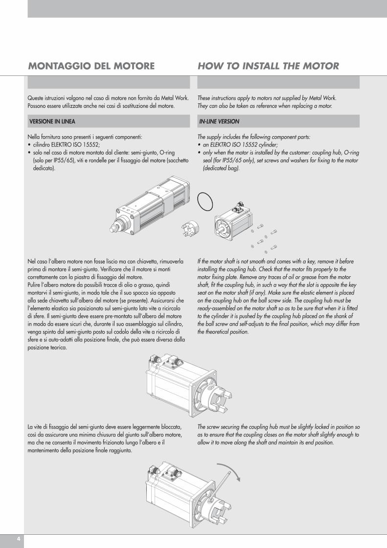
Nella fornitura sono presenti i seguenti componenti:• cilindro ELEKTRO ISO 15552;• solo nel caso di motore montato dal cliente: semi-giunto, O-ring (solo per IP55/65), viti e rondelle per il fissaggio del motore (sacchetto dedicato).
Nel caso l’albero motore non fosse liscio ma con chiavetta, rimuoverla prima di montare il semi-giunto. Verificare che il motore si monti correttamente con la piastra di fissaggio del motore. Pulire l’albero motore da possibili tracce di olio o grasso, quindi montarvi il semi-giunto, in modo tale che il suo spacco sia opposto alla sede chiavetta sull’albero del motore (se presente). Assicurarsi che l’elemento elastico sia posizionato sul semi-giunto lato vite a ricircolo di sfere. Il semi-giunto deve essere pre-montato sull’albero del motore in modo da essere sicuri che, durante il suo assemblaggio sul cilindro, venga spinto dal semi-giunto posto sul codolo della vite a ricircolo di sfere e si auto-adatti alla posizione finale, che può essere diversa dalla posizione teorica.
La vite di fissaggio del semi-giunto deve essere leggermente bloccata, così da assicurare una minima chiusura del giunto sull’albero motore, ma che ne consenta il movimento frizionato lungo l’albero e il mantenimento della posizione finale raggiunta.
If the motor shaft is not smooth and comes with a key, remove it before installing the coupling hub. Check that the motor fits properly to the motor fixing plate. Remove any traces of oil or grease from the motor shaft, fit the coupling hub, in such a way that the slot is opposite the key seat on the motor shaft (if any). Make sure the elastic element is placed on the coupling hub on the ball screw side. The coupling hub must be ready-assembled on the motor shaft so as to be sure that when it is fitted to the cylinder it is pushed by the coupling hub placed on the shank of the ball screw and self-adjusts to the final position, which may differ from the theoretical position.
The screw securing the coupling hub must be slightly locked in position so as to ensure that the coupling closes on the motor shaft slightly enough to allow it to move along the shaft and maintain its end position.
VERSIONE IN LINEA IN-LINE VERSION
MONTAGGIO DEL MOTORE HOW TO INSTALL THE MOTOR
Queste istruzioni valgono nel caso di motore non fornito da Metal Work.Possono essere utilizzate anche nei casi di sostituzione del motore.
These instructions apply to motors not supplied by Metal Work. They can also be taken as reference when replacing a motor.
The supply includes the following component parts:• an ELEKTRO ISO 15552 cylinder;• only when the motor is installed by the customer: coupling hub, O-ring seal (for IP55/65 only), set screws and washers for fixing to the motor (dedicated bag).

5
Montare il motore sul cilindro.Nel caso sia necessario allineare i due semi-giunti ruotare la vite muovendo leggermente avanti o indietro lo stelo del cilindro.
Rimuovere il motore dal cilindro e con il calibro misurare la posizione indicata (x), prestando attenzione a non muovere il semi-giunto assialmente, tirandolo o spingendolo. In caso di dubbio ripetere l‘operazione precedente.
Rispetto alla posizione misurata (x), il giunto deve essere spostato approssimativamente di 0.8-1mm verso il corpo motore. Correggere quindi la posizione allentando la vite di fissaggio.
Place the motor in position onto the cylinder.If necessary, align the two coupling hub and rotate the screw by slightly moving the cylinder piston rod forward and backward.
Remove the motor from the cylinder and measure the position marked (x), using a gauge and taking care not to move the coupling hub axially when pulling or pushing it. In case of doubt, repeat the previous operation.
The coupling must be moved 0.8-1mm apart from the measured position (x) in the direction of the body of the motor. Adjust the position by loosening the set screw.
6
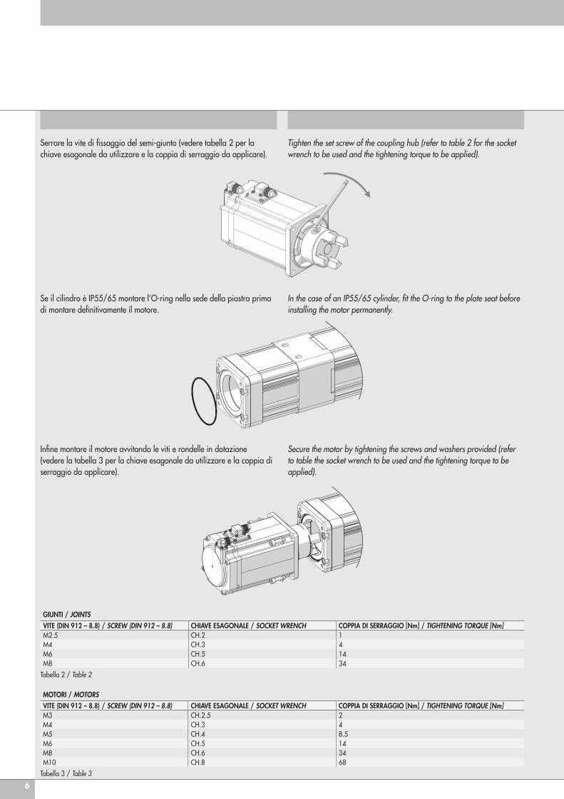
Serrare la vite di fissaggio del semi-giunto (vedere tabella 2 per la chiave esagonale da utilizzare e la coppia di serraggio da applicare).
Se il cilindro è IP55/65 montare l’O-ring nella sede della piastra prima di montare definitivamente il motore.
MOTORI / MOTORSVITE (DIN 912 – 8.8) / SCREW (DIN 912 – 8.8) CHIAVE ESAGONALE / SOCKET WRENCH COPPIA DI SERRAGGIO [Nm] / TIGHTENING TORQUE [Nm]M3 CH.2.5 2M4 CH.3 4M5 CH.4 8.5M6 CH.5 14M8 CH.6 34M10 CH.8 68
Tabella 3 / Table 3
Tighten the set screw of the coupling hub (refer to table 2 for the socket wrench to be used and the tightening torque to be applied).
In the case of an IP55/65 cylinder, fit the O-ring to the plate seat before installing the motor permanently.
GIUNTI / JOINTSVITE (DIN 912 – 8.8) / SCREW (DIN 912 – 8.8) CHIAVE ESAGONALE / SOCKET WRENCH COPPIA DI SERRAGGIO [Nm] / TIGHTENING TORQUE [Nm]M2.5 CH.2 1M4 CH.3 4M6 CH.5 14M8 CH.6 34
Tabella 2 / Table 2
Infine montare il motore avvitando le viti e rondelle in dotazione (vedere la tabella 3 per la chiave esagonale da utilizzare e la coppia di serraggio da applicare).
Secure the motor by tightening the screws and washers provided (refer to table the socket wrench to be used and the tightening torque to be applied).
7
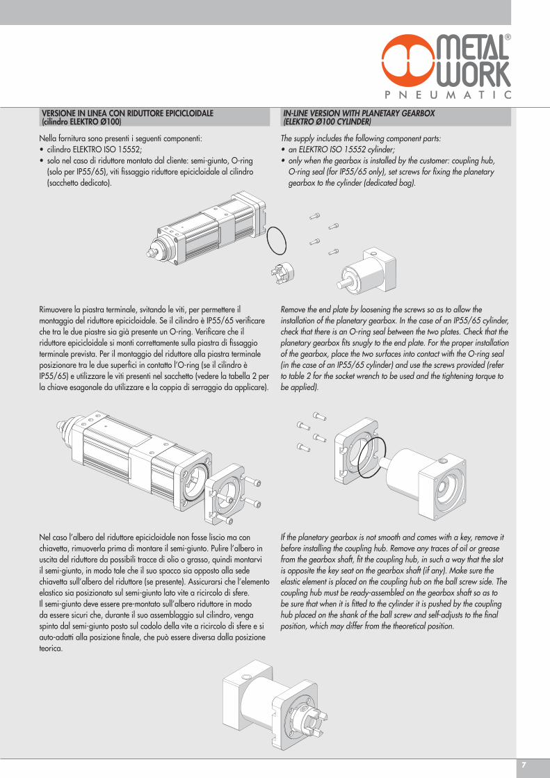
Rimuovere la piastra terminale, svitando le viti, per permettere il montaggio del riduttore epicicloidale. Se il cilindro è IP55/65 verificare che tra le due piastre sia già presente un O-ring. Verificare che il riduttore epicicloidale si monti correttamente sulla piastra di fissaggio terminale prevista. Per il montaggio del riduttore alla piastra terminale posizionare tra le due superfici in contatto l’O-ring (se il cilindro è IP55/65) e utilizzare le viti presenti nel sacchetto (vedere la tabella 2 per la chiave esagonale da utilizzare e la coppia di serraggio da applicare).
Nel caso l’albero del riduttore epicicloidale non fosse liscio ma con chiavetta, rimuoverla prima di montare il semi-giunto. Pulire l’albero in uscita del riduttore da possibili tracce di olio o grasso, quindi montarvi il semi-giunto, in modo tale che il suo spacco sia opposto alla sede chiavetta sull’albero del riduttore (se presente). Assicurarsi che l’elemento elastico sia posizionato sul semi-giunto lato vite a ricircolo di sfere. Il semi-giunto deve essere pre-montato sull’albero riduttore in modo da essere sicuri che, durante il suo assemblaggio sul cilindro, venga spinto dal semi-giunto posto sul codolo della vite a ricircolo di sfere e si auto-adatti alla posizione finale, che può essere diversa dalla posizione teorica.
Remove the end plate by loosening the screws so as to allow the installation of the planetary gearbox. In the case of an IP55/65 cylinder, check that there is an O-ring seal between the two plates. Check that the planetary gearbox fits snugly to the end plate. For the proper installation of the gearbox, place the two surfaces into contact with the O-ring seal (in the case of an IP55/65 cylinder) and use the screws provided (refer to table 2 for the socket wrench to be used and the tightening torque to be applied).
If the planetary gearbox is not smooth and comes with a key, remove it before installing the coupling hub. Remove any traces of oil or grease from the gearbox shaft, fit the coupling hub, in such a way that the slot is opposite the key seat on the gearbox shaft (if any). Make sure the elastic element is placed on the coupling hub on the ball screw side. The coupling hub must be ready-assembled on the gearbox shaft so as to be sure that when it is fitted to the cylinder it is pushed by the coupling hub placed on the shank of the ball screw and self-adjusts to the final position, which may differ from the theoretical position.
Nella fornitura sono presenti i seguenti componenti:• cilindro ELEKTRO ISO 15552;• solo nel caso di riduttore montato dal cliente: semi-giunto, O-ring (solo per IP55/65), viti fissaggio riduttore epicicloidale al cilindro (sacchetto dedicato).
The supply includes the following component parts: • an ELEKTRO ISO 15552 cylinder;• only when the gearbox is installed by the customer: coupling hub, O-ring seal (for IP55/65 only), set screws for fixing the planetary gearbox to the cylinder (dedicated bag).
VERSIONE IN LINEA CON RIDUTTORE EPICICLOIDALE (cilindro ELEKTRO Ø100)
IN-LINE VERSION WITH PLANETARY GEARBOX(ELEKTRO Ø100 CYLINDER)
8
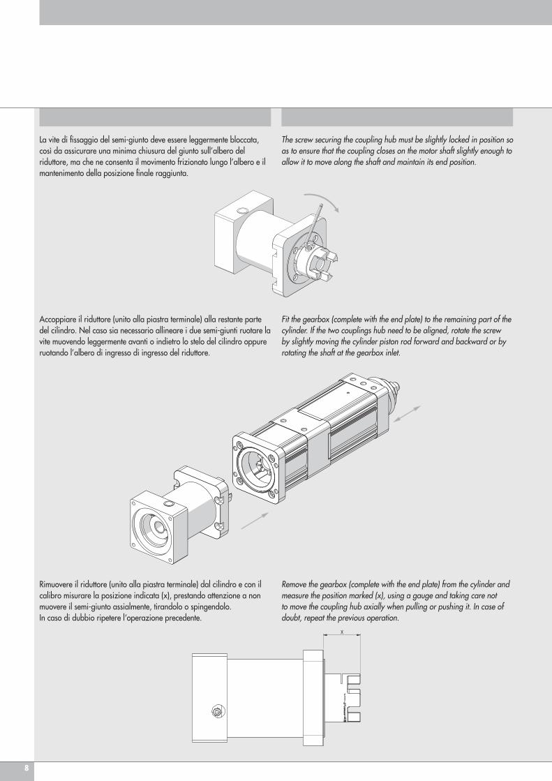
La vite di fissaggio del semi-giunto deve essere leggermente bloccata, così da assicurare una minima chiusura del giunto sull’albero del riduttore, ma che ne consenta il movimento frizionato lungo l’albero e il mantenimento della posizione finale raggiunta.
Accoppiare il riduttore (unito alla piastra terminale) alla restante parte del cilindro. Nel caso sia necessario allineare i due semi-giunti ruotare la vite muovendo leggermente avanti o indietro lo stelo del cilindro oppure ruotando l’albero di ingresso di ingresso del riduttore.
Rimuovere il riduttore (unito alla piastra terminale) dal cilindro e con il calibro misurare la posizione indicata (x), prestando attenzione a non muovere il semi-giunto assialmente, tirandolo o spingendolo. In caso di dubbio ripetere l‘operazione precedente.
The screw securing the coupling hub must be slightly locked in position so as to ensure that the coupling closes on the motor shaft slightly enough to allow it to move along the shaft and maintain its end position.
Fit the gearbox (complete with the end plate) to the remaining part of the cylinder. If the two couplings hub need to be aligned, rotate the screw by slightly moving the cylinder piston rod forward and backward or by rotating the shaft at the gearbox inlet.
Remove the gearbox (complete with the end plate) from the cylinder and measure the position marked (x), using a gauge and taking care not to move the coupling hub axially when pulling or pushing it. In case of doubt, repeat the previous operation.

9
Serrare la vite di fissaggio del semi-giunto (vedere tabella 4 per la chiave esagonale da utilizzare e la coppia di serraggio da applicare).
Tighten the set screw of the coupling hub (refer to table 4 for the socket wrench to be used and the tightening torque to be applied).
Rispetto alla posizione misurata (x), il giunto deve essere spostato approssimativamente di 0.8-1mm verso il corpo riduttore. Correggere, quindi, la posizione allentando la vite di fissaggio.
The coupling must be moved 0.8-1mm apart from the measured position (x) in the direction of the body of the gearbox. Adjust the position by loosening the set screw.
Infine rimontare il riduttore al cilindro con le viti in dotazione (vedere la tabella 5 per la chiave esagonale da utilizzare e la coppia di serraggio da applicare).
Secure the gearbox to the cylinder by tightening the screws provided (refer to table 5 for the socket wrench to be used and the tightening torque to be applied).
10
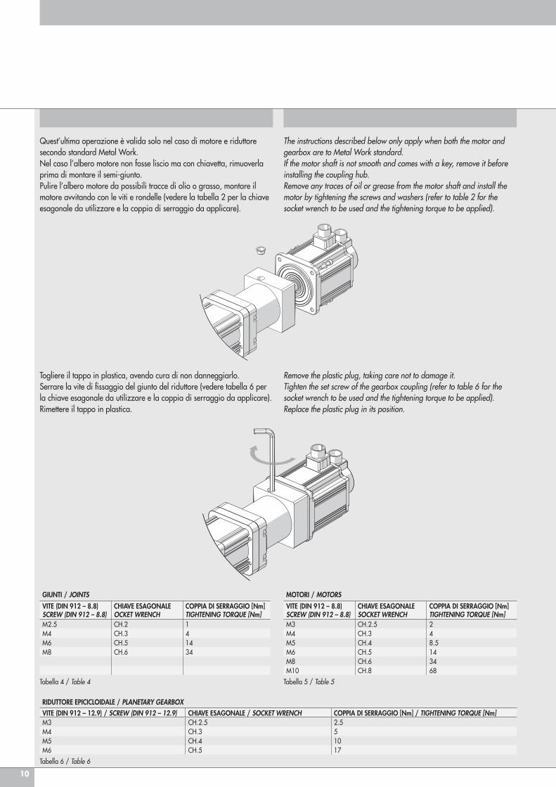
Togliere il tappo in plastica, avendo cura di non danneggiarlo. Serrare la vite di fissaggio del giunto del riduttore (vedere tabella 6 per la chiave esagonale da utilizzare e la coppia di serraggio da applicare). Rimettere il tappo in plastica.
Remove the plastic plug, taking care not to damage it. Tighten the set screw of the gearbox coupling (refer to table 6 for the socket wrench to be used and the tightening torque to be applied). Replace the plastic plug in its position.
MOTORI / MOTORS
VITE (DIN 912 – 8.8)SCREW (DIN 912 – 8.8)
CHIAVE ESAGONALESOCKET WRENCH
COPPIA DI SERRAGGIO [Nm]TIGHTENING TORQUE [Nm]
M3 CH.2.5 2M4 CH.3 4M5 CH.4 8.5M6 CH.5 14M8 CH.6 34M10 CH.8 68
Tabella 5 / Table 5
GIUNTI / JOINTS
VITE (DIN 912 – 8.8)SCREW (DIN 912 – 8.8)
CHIAVE ESAGONALEOCKET WRENCH
COPPIA DI SERRAGGIO [Nm]TIGHTENING TORQUE [Nm]
M2.5 CH.2 1M4 CH.3 4M6 CH.5 14M8 CH.6 34
Tabella 4 / Table 4
RIDUTTORE EPICICLOIDALE / PLANETARY GEARBOXVITE (DIN 912 – 12.9) / SCREW (DIN 912 – 12.9) CHIAVE ESAGONALE / SOCKET WRENCH COPPIA DI SERRAGGIO [Nm] / TIGHTENING TORQUE [Nm]M3 CH.2.5 2.5M4 CH.3 5M5 CH.4 10M6 CH.5 17
Tabella 6 / Table 6
Quest’ultima operazione è valida solo nel caso di motore e riduttore secondo standard Metal Work.Nel caso l’albero motore non fosse liscio ma con chiavetta, rimuoverla prima di montare il semi-giunto.Pulire l’albero motore da possibili tracce di olio o grasso, montare il motore avvitando con le viti e rondelle (vedere la tabella 2 per la chiave esagonale da utilizzare e la coppia di serraggio da applicare).
The instructions described below only apply when both the motor and gearbox are to Metal Work standard. If the motor shaft is not smooth and comes with a key, remove it before installing the coupling hub.Remove any traces of oil or grease from the motor shaft and install the motor by tightening the screws and washers (refer to table 2 for the socket wrench to be used and the tightening torque to be applied).
11
VERSIONE RINVIATA GEARED VERSION
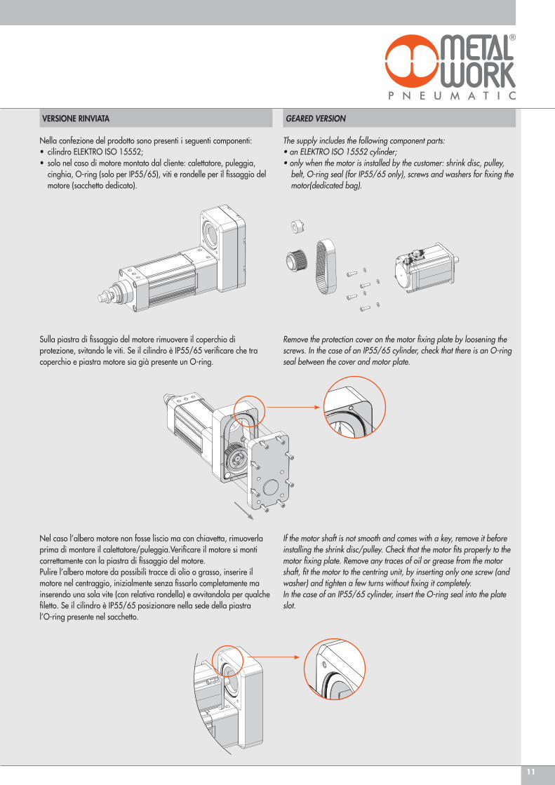
Nella confezione del prodotto sono presenti i seguenti componenti:• cilindro ELEKTRO ISO 15552;• solo nel caso di motore montato dal cliente: calettatore, puleggia, cinghia, O-ring (solo per IP55/65), viti e rondelle per il fissaggio del motore (sacchetto dedicato).
Sulla piastra di fissaggio del motore rimuovere il coperchio di protezione, svitando le viti. Se il cilindro è IP55/65 verificare che tra coperchio e piastra motore sia già presente un O-ring.
Nel caso l’albero motore non fosse liscio ma con chiavetta, rimuoverla prima di montare il calettatore/puleggia.Verificare il motore si monti correttamente con la piastra di fissaggio del motore. Pulire l’albero motore da possibili tracce di olio o grasso, inserire il motore nel centraggio, inizialmente senza fissarlo completamente ma inserendo una sola vite (con relativa rondella) e avvitandola per qualche filetto. Se il cilindro è IP55/65 posizionare nella sede della piastra l’O-ring presente nel sacchetto.
Remove the protection cover on the motor fixing plate by loosening the screws. In the case of an IP55/65 cylinder, check that there is an O-ring seal between the cover and motor plate.
If the motor shaft is not smooth and comes with a key, remove it before installing the shrink disc/pulley. Check that the motor fits properly to the motor fixing plate. Remove any traces of oil or grease from the motor shaft, fit the motor to the centring unit, by inserting only one screw (and washer) and tighten a few turns without fixing it completely. In the case of an IP55/65 cylinder, insert the O-ring seal into the plate slot.
The supply includes the following component parts: • an ELEKTRO ISO 15552 cylinder;• only when the motor is installed by the customer: shrink disc, pulley, belt, O-ring seal (for IP55/65 only), screws and washers for fixing the motor(dedicated bag).
12
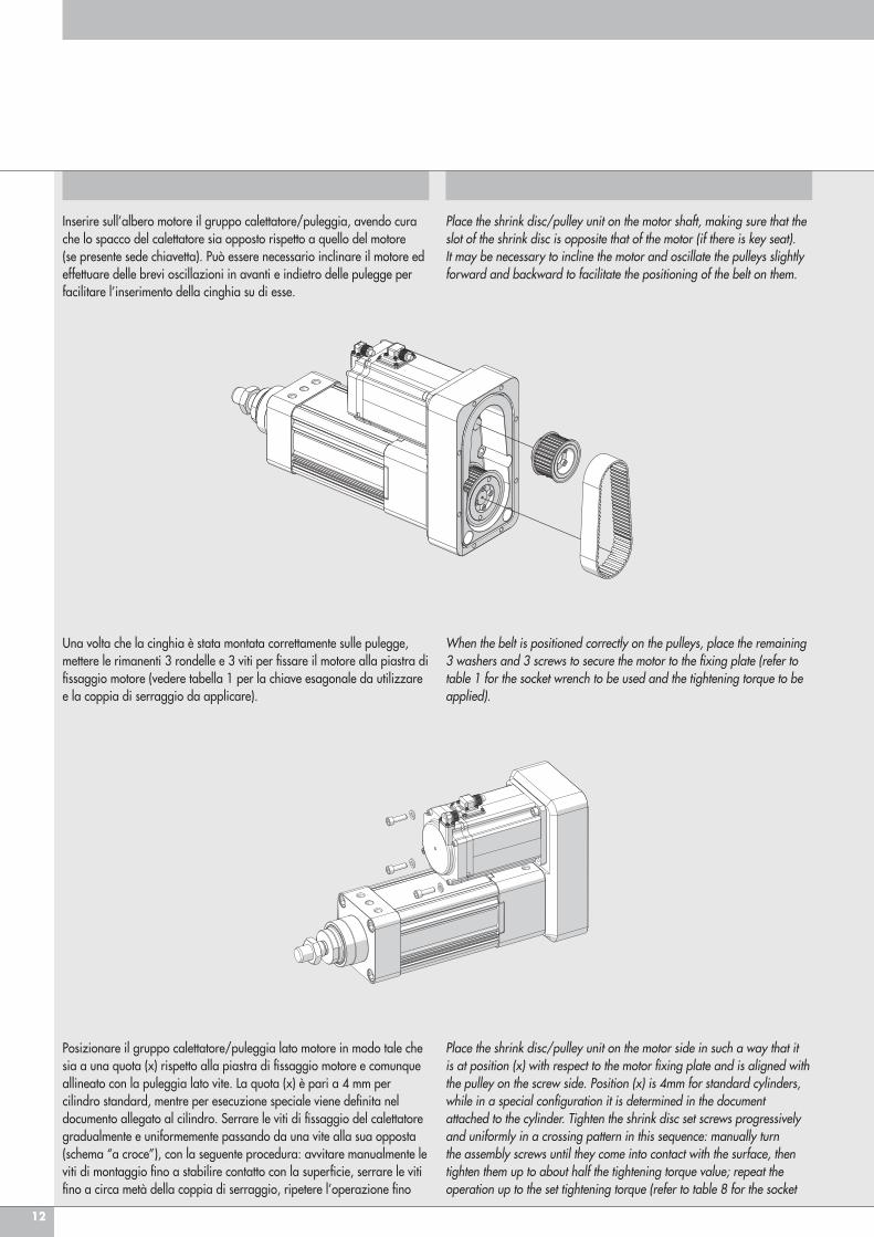
Inserire sull’albero motore il gruppo calettatore/puleggia, avendo cura che lo spacco del calettatore sia opposto rispetto a quello del motore (se presente sede chiavetta). Può essere necessario inclinare il motore ed effettuare delle brevi oscillazioni in avanti e indietro delle pulegge per facilitare l’inserimento della cinghia su di esse.
Place the shrink disc/pulley unit on the motor shaft, making sure that the slot of the shrink disc is opposite that of the motor (if there is key seat). It may be necessary to incline the motor and oscillate the pulleys slightly forward and backward to facilitate the positioning of the belt on them.
Una volta che la cinghia è stata montata correttamente sulle pulegge, mettere le rimanenti 3 rondelle e 3 viti per fissare il motore alla piastra di fissaggio motore (vedere tabella 1 per la chiave esagonale da utilizzare e la coppia di serraggio da applicare).
When the belt is positioned correctly on the pulleys, place the remaining 3 washers and 3 screws to secure the motor to the fixing plate (refer to table 1 for the socket wrench to be used and the tightening torque to be applied).
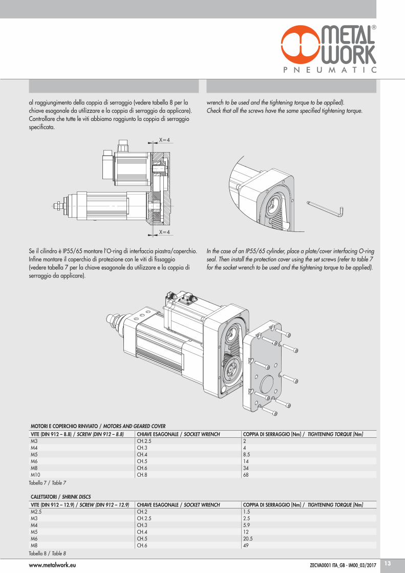
Posizionare il gruppo calettatore/puleggia lato motore in modo tale che sia a una quota (x) rispetto alla piastra di fissaggio motore e comunque allineato con la puleggia lato vite. La quota (x) è pari a 4 mm per cilindro standard, mentre per esecuzione speciale viene definita nel documento allegato al cilindro. Serrare le viti di fissaggio del calettatore gradualmente e uniformemente passando da una vite alla sua opposta (schema “a croce”), con la seguente procedura: avvitare manualmente le viti di montaggio fino a stabilire contatto con la superficie, serrare le viti fino a circa metà della coppia di serraggio, ripetere l’operazione fino
Place the shrink disc/pulley unit on the motor side in such a way that it is at position (x) with respect to the motor fixing plate and is aligned with the pulley on the screw side. Position (x) is 4mm for standard cylinders, while in a special configuration it is determined in the document attached to the cylinder. Tighten the shrink disc set screws progressively and uniformly in a crossing pattern in this sequence: manually turn the assembly screws until they come into contact with the surface, then tighten them up to about half the tightening torque value; repeat the operation up to the set tightening torque (refer to table 8 for the socket
13
CALETTATORI / SHRINK DISCSVITE (DIN 912 – 12.9) / SCREW (DIN 912 – 12.9) CHIAVE ESAGONALE / SOCKET WRENCH COPPIA DI SERRAGGIO [Nm] / TIGHTENING TORQUE [Nm]M2.5 CH.2 1.5M3 CH.2.5 2.5M4 CH.3 5.9M5 CH.4 12M6 CH.5 20.5M8 CH.6 49
Tabella 8 / Table 8
MOTORI E COPERCHIO RINVIATO / MOTORS AND GEARED COVERVITE (DIN 912 – 8.8) / SCREW (DIN 912 – 8.8) CHIAVE ESAGONALE / SOCKET WRENCH COPPIA DI SERRAGGIO [Nm] / TIGHTENING TORQUE [Nm]M3 CH.2.5 2M4 CH.3 4M5 CH.4 8.5M6 CH.5 14M8 CH.6 34M10 CH.8 68
Tabella 7 / Table 7
Se il cilindro è IP55/65 montare l’O-ring di interfaccia piastra/coperchio.Infine montare il coperchio di protezione con le viti di fissaggio (vedere tabella 7 per la chiave esagonale da utilizzare e la coppia di serraggio da applicare).
In the case of an IP55/65 cylinder, place a plate/cover interfacing O-ring seal. Then install the protection cover using the set screws (refer to table 7 for the socket wrench to be used and the tightening torque to be applied).
www.metalwork.eu ZECVA0001 ITA_GB - IM00_03/2017
al raggiungimento della coppia di serraggio (vedere tabella 8 per la chiave esagonale da utilizzare e la coppia di serraggio da applicare). Controllare che tutte le viti abbiamo raggiunto la coppia di serraggio specificata.
wrench to be used and the tightening torque to be applied).Check that all the screws have the same specified tightening torque.