ISOTRON - ISOPLUS - ISOPLUS LITE - ISOCONCEPT · Le caratteristiche dell'acqua devono essere...
126
Transcript of ISOTRON - ISOPLUS - ISOPLUS LITE - ISOCONCEPT · Le caratteristiche dell'acqua devono essere...

1
ISOTRON - ISOPLUS - ISOPLUS LITE - ISOCONCEPT
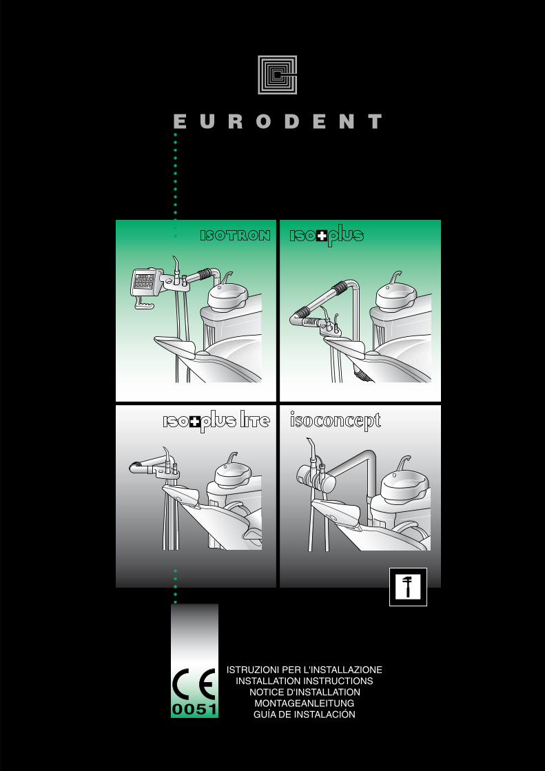
Istruzioni per l’installazione
ITALIANO .............Pag. 1
ENGLISH ...............Page 25
FRANÇAIS ............ Page 49
DEUTSCH ..............Seite 73
ESPAÑOL .............Hoja 97

1
ISOTRON - ISOPLUS - ISOPLUS LITE - ISOCONCEPT
Istruzioni per l’installazione
PREREQUISITI ............................................................................................................ 2DICHIARAZIONE DI RESPONSABILITÀ ........................................................................ 2PREDISPOSIZIONE ....................................................................................................3
A IMBALLO DELLE POLTRONE ISORAMA ED ISO ........................................................4TRASPORTO ED INSTALLAZIONE ..........................................................................5
B INSTALLAZIONE DELLA POLTRONA ISORAMA .......................................................6PREPARAZIONE ................................................................................................... 6SBLOCCAGGIO SPALLIERA ...................................................................................6FISSAGGIO SPALLIERA .........................................................................................6PROVA DI FUNZIONAMENTO ..............................................................................7CUSCINO SPALLIERA ............................................................................................7CUSCINO SEDILE .................................................................................................8
C INSTALLAZIONE POLTRONA ISO...........................................................................9SPALLIERA ............................................................................................................ 9TAPPEZZERIA SPALLIERA .......................................................................................9TAPPEZZERIA SEDILE .......................................................................................... 10MONTAGGIO BRACCIOLI .................................................................................. 10
D POGGIATESTA POLTRONE ISORAMA ED ISO ....................................................... 12
E INSTALLAZIONE DEI RIUNITIISOTRON, ISOPLUS, ISOPLUS LITE, ISOCONCEPT .................................................13
F COLLEGAMENTI ELETTRICI ED ELETTROPNEUMATICI ............................................. 18ISOTRON, ISOPLUS, ISOPLUS LITE ....................................................................... 18ISOCONCEPT .................................................................................................... 20
G COLLEGAMENTI DELLA POMPA ASPIRANTE ......................................................... 22
H PREDISPOSIZIONE LAMPADA ISOSUN PER ISOTRON, ISOPLUS, ISOPLUS LITE ....... 22
I REGOLAZIONI ISOCONCEPT ............................................................................... 23REGOLAZIONE PRESSIONE AGLI STRUMENTI ..................................................... 23FUNZIONI DEI TRIMMER ..................................................................................... 23
INDICE Pag.
2
ISOTRON - ISOPLUS - ISOPLUS LITE - ISOCONCEPT
Istruzioni per l’installazione
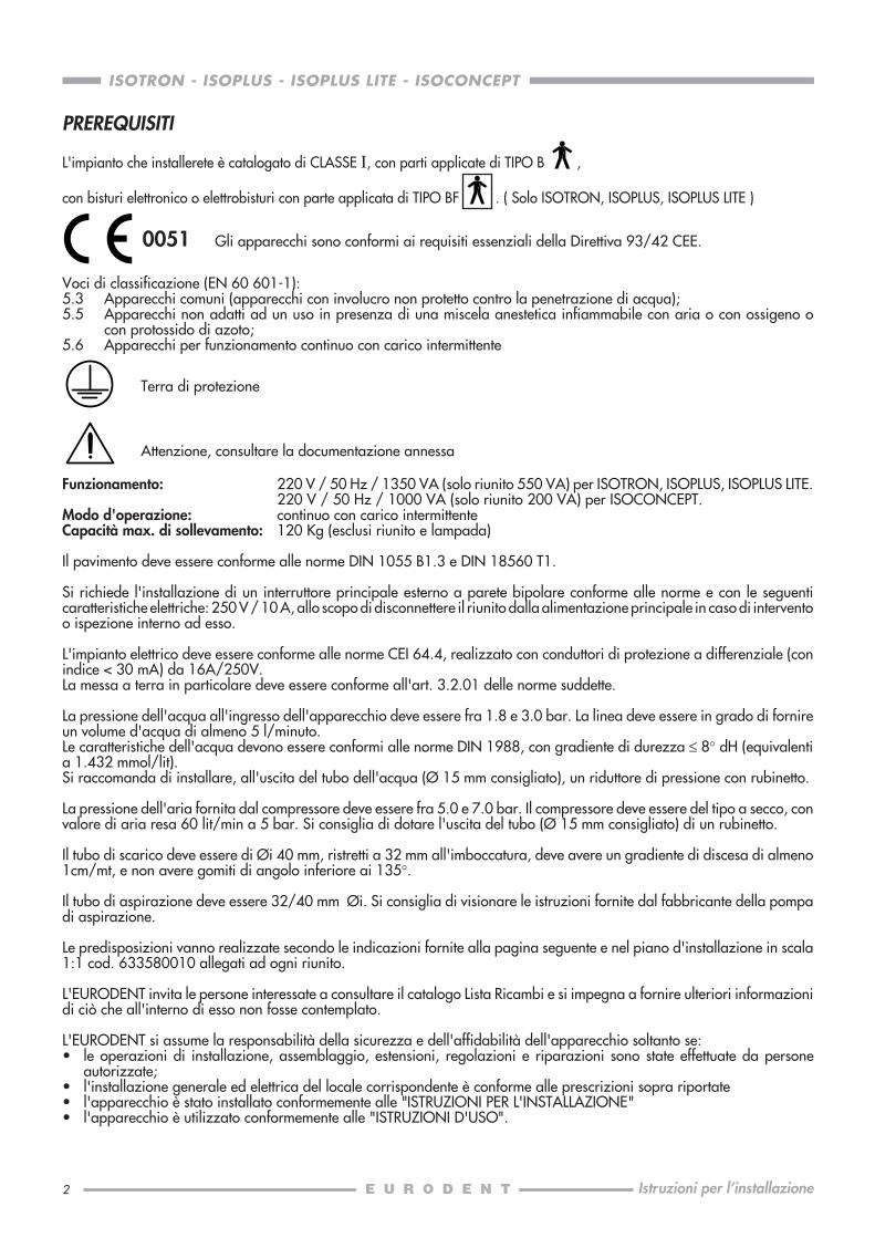
PREREQUISITI
L'impianto che installerete è catalogato di CLASSE I, con parti applicate di TIPO B ,
con bisturi elettronico o elettrobisturi con parte applicata di TIPO BF . ( Solo ISOTRON, ISOPLUS, ISOPLUS LITE )
Voci di classificazione (EN 60 601-1):5.3 Apparecchi comuni (apparecchi con involucro non protetto contro la penetrazione di acqua);5.5 Apparecchi non adatti ad un uso in presenza di una miscela anestetica infiammabile con aria o con ossigeno o
con protossido di azoto;5.6 Apparecchi per funzionamento continuo con carico intermittente
Funzionamento: 220 V / 50 Hz / 1350 VA (solo riunito 550 VA) per ISOTRON, ISOPLUS, ISOPLUS LITE.220 V / 50 Hz / 1000 VA (solo riunito 200 VA) per ISOCONCEPT.
Modo d'operazione: continuo con carico intermittenteCapacità max. di sollevamento: 120 Kg (esclusi riunito e lampada)
Il pavimento deve essere conforme alle norme DIN 1055 B1.3 e DIN 18560 T1.
Si richiede l'installazione di un interruttore principale esterno a parete bipolare conforme alle norme e con le seguenticaratteristiche elettriche: 250 V / 10 A, allo scopo di disconnettere il riunito dalla alimentazione principale in caso di interventoo ispezione interno ad esso.
L'impianto elettrico deve essere conforme alle norme CEI 64.4, realizzato con conduttori di protezione a differenziale (conindice < 30 mA) da 16A/250V.La messa a terra in particolare deve essere conforme all'art. 3.2.01 delle norme suddette.
La pressione dell'acqua all'ingresso dell'apparecchio deve essere fra 1.8 e 3.0 bar. La linea deve essere in grado di fornireun volume d'acqua di almeno 5 l/minuto.Le caratteristiche dell'acqua devono essere conformi alle norme DIN 1988, con gradiente di durezza ≤ 8° dH (equivalentia 1.432 mmol/lit).Si raccomanda di installare, all'uscita del tubo dell'acqua (Ø 15 mm consigliato), un riduttore di pressione con rubinetto.
La pressione dell'aria fornita dal compressore deve essere fra 5.0 e 7.0 bar. Il compressore deve essere del tipo a secco, convalore di aria resa 60 lit/min a 5 bar. Si consiglia di dotare l'uscita del tubo (Ø 15 mm consigliato) di un rubinetto.
Il tubo di scarico deve essere di Øi 40 mm, ristretti a 32 mm all'imboccatura, deve avere un gradiente di discesa di almeno1cm/mt, e non avere gomiti di angolo inferiore ai 135°.
Il tubo di aspirazione deve essere 32/40 mm Øi. Si consiglia di visionare le istruzioni fornite dal fabbricante della pompadi aspirazione.
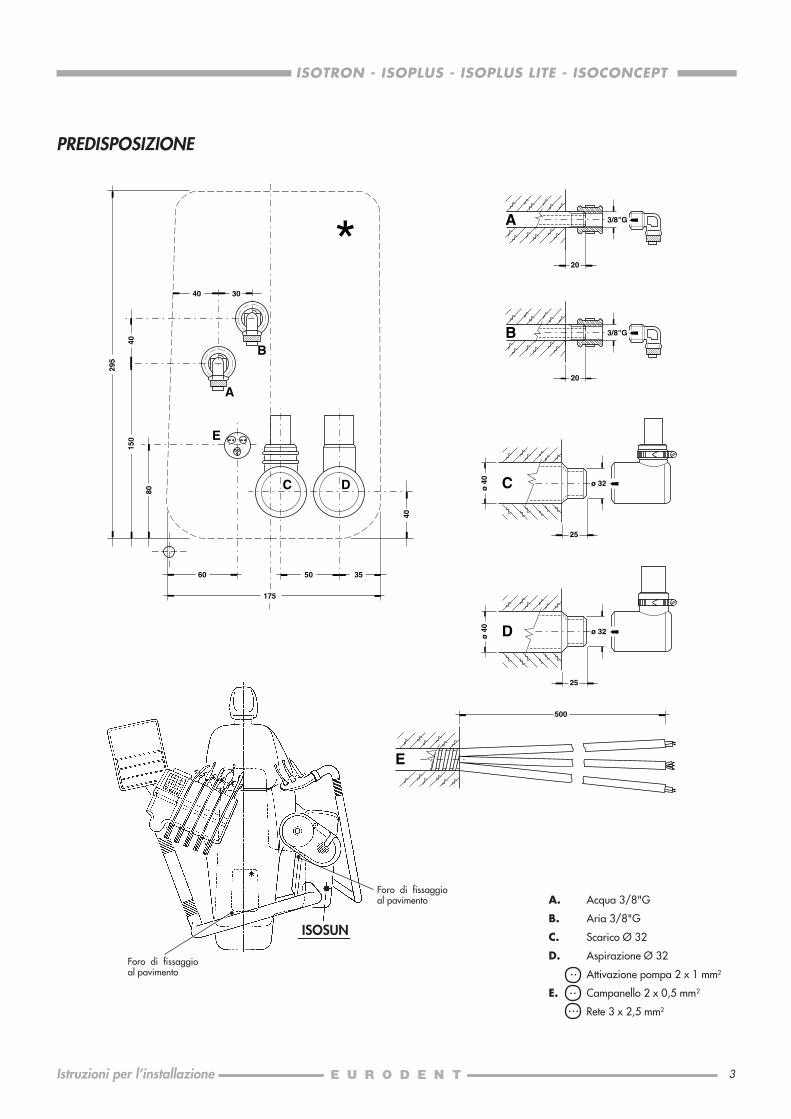
Le predisposizioni vanno realizzate secondo le indicazioni fornite alla pagina seguente e nel piano d'installazione in scala1:1 cod. 633580010 allegati ad ogni riunito.
L'EURODENT invita le persone interessate a consultare il catalogo Lista Ricambi e si impegna a fornire ulteriori informazionidi ciò che all'interno di esso non fosse contemplato.
L'EURODENT si assume la responsabilità della sicurezza e dell'affidabilità dell'apparecchio soltanto se:• le operazioni di installazione, assemblaggio, estensioni, regolazioni e riparazioni sono state effettuate da persone
autorizzate;• l'installazione generale ed elettrica del locale corrispondente è conforme alle prescrizioni sopra riportate• l'apparecchio è stato installato conformemente alle "ISTRUZIONI PER L'INSTALLAZIONE"• l'apparecchio è utilizzato conformemente alle "ISTRUZIONI D'USO".
0051 Gli apparecchi sono conformi ai requisiti essenziali della Direttiva 93/42 CEE.
Terra di protezione
Attenzione, consultare la documentazione annessa
3
ISOTRON - ISOPLUS - ISOPLUS LITE - ISOCONCEPT
Istruzioni per l’installazione
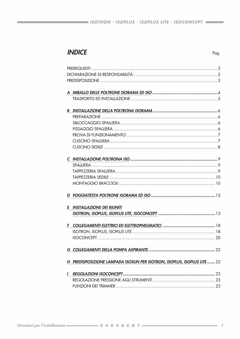
PREDISPOSIZIONE
..
.....
A. Acqua 3/8"G
B. Aria 3/8"G
C. Scarico Ø 32
D. Aspirazione Ø 32
Attivazione pompa 2 x 1 mm2
E. Campanello 2 x 0,5 mm2
Rete 3 x 2,5 mm2
5060
175
E
A
A 3/8"G
20
B
C D
35
295
150
80
40
40 30
40
B
C
3/8"G
20
25
ø 32ø
40
D
E
25
500
ø 32
ø 4
0
Foro di fissaggioal pavimento
Foro di fissaggioal pavimento
ISOSUN
4
ISOTRON - ISOPLUS - ISOPLUS LITE - ISOCONCEPT
Istruzioni per l’installazione
A0
1
ALTO
BOLOGNA
ITALYCOD OPZIONEMATR.
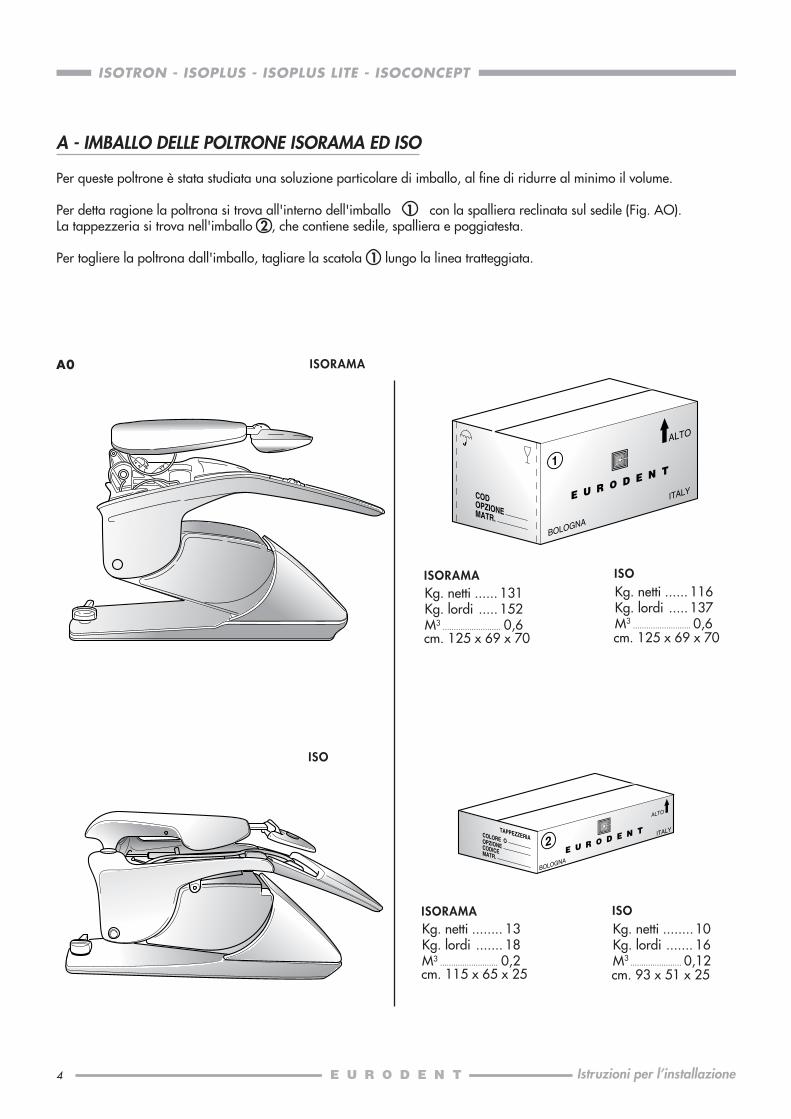
Kg. netti ...... 131Kg. lordi ..... 152M3 .......................... 0,6cm. 125 x 69 x 70
2
ALTO
BOLOGNA
ITALYCOLORE OOPZIONE
TAPPEZZERIA
CODICEMATR.
A - IMBALLO DELLE POLTRONE ISORAMA ED ISO
Per queste poltrone è stata studiata una soluzione particolare di imballo, al fine di ridurre al minimo il volume.
Per detta ragione la poltrona si trova all'interno dell'imballo 1 con la spalliera reclinata sul sedile (Fig. AO).La tappezzeria si trova nell'imballo 2 , che contiene sedile, spalliera e poggiatesta.
Per togliere la poltrona dall'imballo, tagliare la scatola 1 lungo la linea tratteggiata.
ISORAMAKg. netti ...... 116Kg. lordi ..... 137M3 .......................... 0,6cm. 125 x 69 x 70
ISO
Kg. netti ........ 13Kg. lordi ....... 18M3 .......................... 0,2cm. 115 x 65 x 25
ISORAMAKg. netti ........ 10Kg. lordi ....... 16M3 ....................... 0,12cm. 93 x 51 x 25
ISO
ISORAMA
ISO
5
ISOTRON - ISOPLUS - ISOPLUS LITE - ISOCONCEPT
Istruzioni per l’installazione
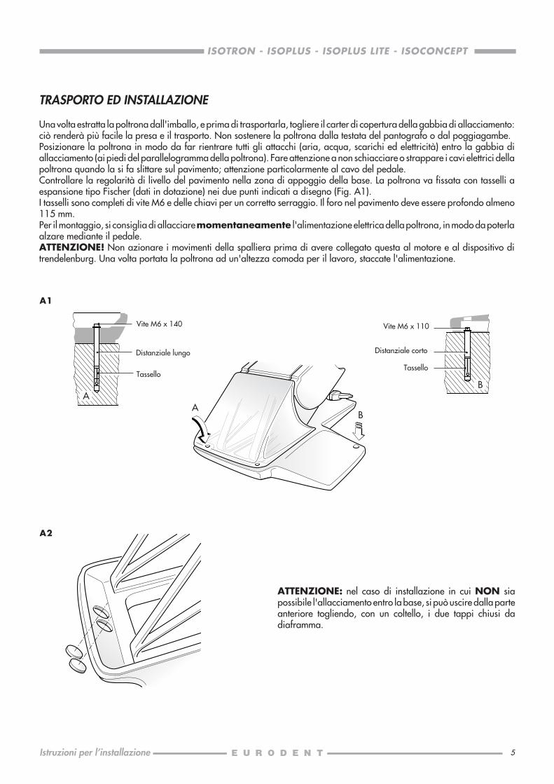
TRASPORTO ED INSTALLAZIONE
Una volta estratta la poltrona dall'imballo, e prima di trasportarla, togliere il carter di copertura della gabbia di allacciamento:ciò renderà più facile la presa e il trasporto. Non sostenere la poltrona dalla testata del pantografo o dal poggiagambe.Posizionare la poltrona in modo da far rientrare tutti gli attacchi (aria, acqua, scarichi ed elettricità) entro la gabbia diallacciamento (ai piedi del parallelogramma della poltrona). Fare attenzione a non schiacciare o strappare i cavi elettrici dellapoltrona quando la si fa slittare sul pavimento; attenzione particolarmente al cavo del pedale.Controllare la regolarità di livello del pavimento nella zona di appoggio della base. La poltrona va fissata con tasselli aespansione tipo Fischer (dati in dotazione) nei due punti indicati a disegno (Fig. A1).I tasselli sono completi di vite M6 e delle chiavi per un corretto serraggio. Il foro nel pavimento deve essere profondo almeno115 mm.Per il montaggio, si consiglia di allacciare momentaneamente l'alimentazione elettrica della poltrona, in modo da poterlaalzare mediante il pedale.ATTENZIONE! Non azionare i movimenti della spalliera prima di avere collegato questa al motore e al dispositivo ditrendelenburg. Una volta portata la poltrona ad un'altezza comoda per il lavoro, staccate l'alimentazione.
A1
ATTENZIONE: nel caso di installazione in cui NON siapossibile l'allacciamento entro la base, si può uscire dalla parteanteriore togliendo, con un coltello, i due tappi chiusi dadiaframma.
A2
B
Vite M6 x 140
Tassello
A
Distanziale lungo
A
B
Vite M6 x 110
Distanziale corto
Tassello

6
ISOTRON - ISOPLUS - ISOPLUS LITE - ISOCONCEPT
Istruzioni per l’installazione
PREPARAZIONE
Posizionata la poltrona, togliere il bracciolo svitando i 2 dadiM6 con una chiave da 10 mm.Tagliare le 2 fascette di plastica che trattengono la vite senzafine del motore spalliera ed il tirante del Trendelenburg.
SBLOCCAGGIO SPALLIERA
Dopo avere allentato con una chiave esagonale da 6 mm ilgrano M4, togliere dal fulcro il perno spalliera con una chiaveesagonale da 6 mm.
N.B.: fare attenzione alla rondella di rasamento.
FISSAGGIO SPALLIERA
Sollevare la spalliera fino a fare coincidere il punto di attaccoall'occhiello della vite senza fine, e infilare il perno spalliera.
Con la chiave esagonale serrare fino in fondo, poi si allenti dica. 30° (meno di 1/4 di giro della chiave), questo perché ilperno giri bene e con poco gioco.Quindi bloccare stringendo il grano M4.Togliere il cubo di polistirolo di protezione del poggiatesta.
B1
B2
B3
B - INSTALLAZIONE DELLA POLTRONA ISORAMA
7
ISOTRON - ISOPLUS - ISOPLUS LITE - ISOCONCEPT
Istruzioni per l’installazione
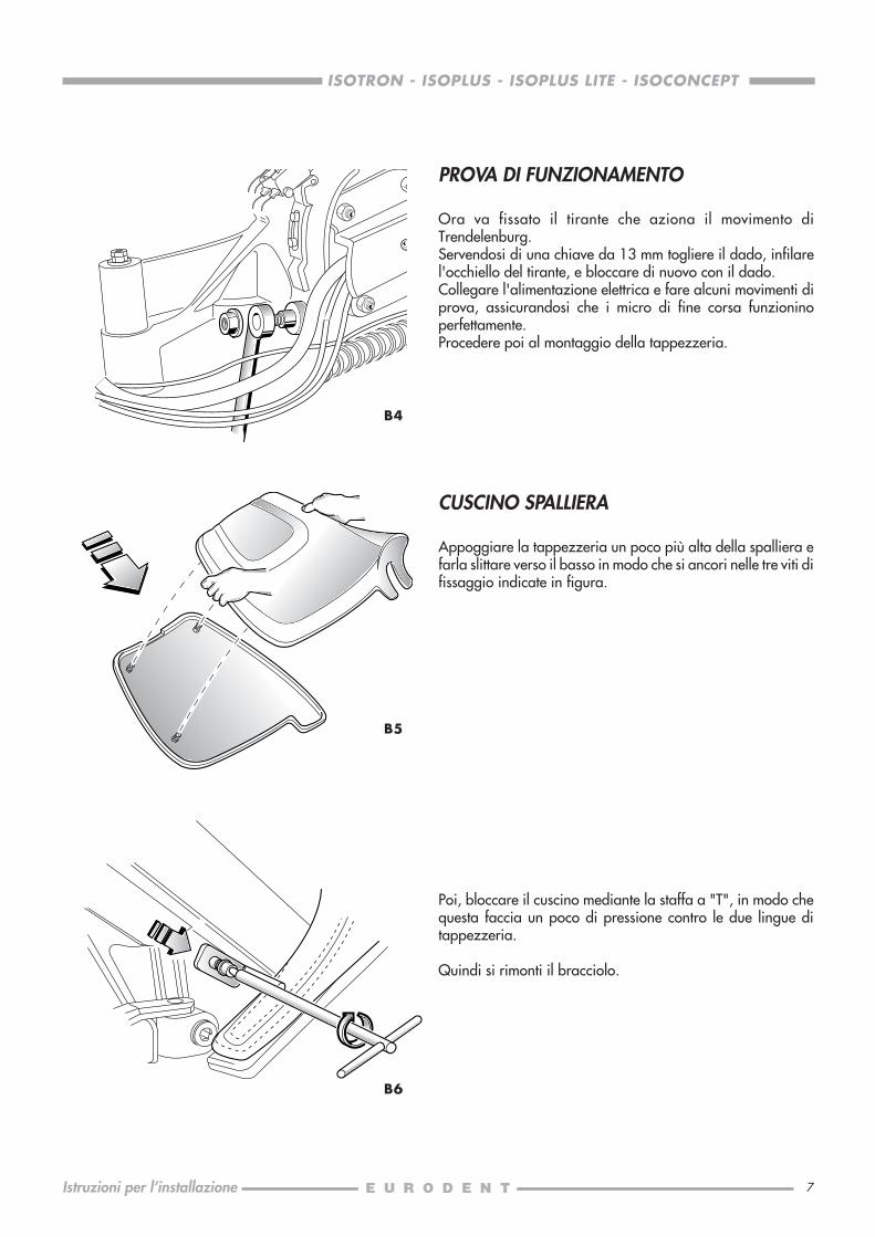
PROVA DI FUNZIONAMENTO
Ora va fissato il tirante che aziona il movimento diTrendelenburg.Servendosi di una chiave da 13 mm togliere il dado, infilarel'occhiello del tirante, e bloccare di nuovo con il dado.Collegare l'alimentazione elettrica e fare alcuni movimenti diprova, assicurandosi che i micro di fine corsa funzioninoperfettamente.Procedere poi al montaggio della tappezzeria.
B4
CUSCINO SPALLIERA
Appoggiare la tappezzeria un poco più alta della spalliera efarla slittare verso il basso in modo che si ancori nelle tre viti difissaggio indicate in figura.
Poi, bloccare il cuscino mediante la staffa a "T", in modo chequesta faccia un poco di pressione contro le due lingue ditappezzeria.
Quindi si rimonti il bracciolo.
B6
B5

8
ISOTRON - ISOPLUS - ISOPLUS LITE - ISOCONCEPT
Istruzioni per l’installazione
B8
CUSCINO SEDILE
Collegare il cavo di terra come indicato in figura.
Se non sono già montati, si avvitino i grani sull'inserto (il lungonel foro esterno posteriore) e si fissino con il controdado.Fissare inoltre i due grani della parte anteriore.
Poi come da figura si posizioni la tappezzeria infilando benei grani entro i fori.
Bloccare il cuscino stringendo sui grani i relativi dadi cilindricilunghi.Per questa operazione servirsi della chiave lunga in dotazione.
Per il fissaggio della parte anteriore utilizzare le viti di M4 x 40.
B10
B7
B9
9
ISOTRON - ISOPLUS - ISOPLUS LITE - ISOCONCEPT
Istruzioni per l’installazione
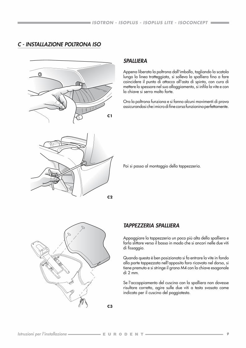
C - INSTALLAZIONE POLTRONA ISO
SPALLIERA
Appena liberata la poltrona dall'imballo, tagliando la scatolalungo la linea tratteggiata, si solleva la spalliera fino a farecoincidere il punto di attacco all'asta di spinta, con cura dimettere lo spessore nel suo alloggiamento, si infila la vite e conla chiave si serra molto forte.
Ora la poltrona funziona e si fanno alcuni movimenti di provaassicurandosi che i micro di fine corsa funzionino perfettamente.
Poi si passa al montaggio della tappezzeria.
C2
TAPPEZZERIA SPALLIERA
Appoggiare la tappezzeria un poco più alta della spalliera efarla slittare verso il basso in modo che si ancori nelle due vitidi fissaggio.
Quando questa è ben posizionata si fa entrare la vite in fondoalla parte tappezzata nell'apposito foro ricavato nel dorso, sitiene premuto e si stringe il grano M4 con la chiave esagonaledi 2 mm.
Se l'accoppiamento del cuscino con la spalliera non dovesserisultare corretto, agire sulle due viti a testa svasata comeindicato per il cuscino del poggiatesta.
C3
C1

10
ISOTRON - ISOPLUS - ISOPLUS LITE - ISOCONCEPT
Istruzioni per l’installazione
TAPPEZZERIA SEDILE
Si posiziona il cuscino sul sedile e si fissa a mezzo delle tre vitiM4, che sporgono sotto, stringendo bene i dadi in modo da fareun corpo unico.
C4
MONTAGGIO BRACCIOLI
Prima operazione: infilare lo spinotto sagomato Ø 8nell'alloggiamento della spalliera, con la parte del bracciolo a90° rispetto alla spalliera cioè con la fresatura sulla punta delperno parallela al profilo anteriore della spalliera stessa.
C5
Ruotando il bracciolo, il perno rimane inserito, quindi procedereal fissaggio della parte inferiore del medesimo.
C6

11
ISOTRON - ISOPLUS - ISOPLUS LITE - ISOCONCEPT
Istruzioni per l’installazione
Per quanto riguarda il sinistro il fissaggio si ottiene mediante ilsuo bullone, mentre il bracciolo destro si infila nel carrelloscorrevole.
C7
Il bracciolo destro è scorrevole, per sbloccarlo dal punto fissobasta tirare verso l'alto la parte anteriore.
C8
C9
C10
Detto bracciolo si dispone anche in angolo negativo e puòanche in questa posizione seguire i movimenti della spalliera.
Si toglie con facilità portando in posizione giusta la linguettamobile che completa il perno sfilabile, poi si procede sfilandoil perno dalla spalliera seguendo l'ordine inverso delladescrizione in oggetto.
Fare scorrere il bracciolo verso la parte anteriore della poltrona,portandolo a fine corsa sul carrello di scorrimento.
12
ISOTRON - ISOPLUS - ISOPLUS LITE - ISOCONCEPT
Istruzioni per l’installazione
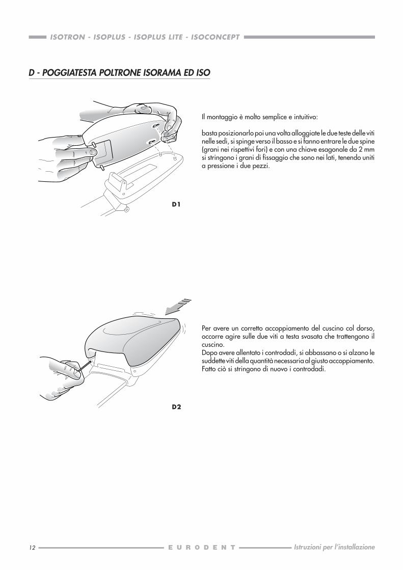
Il montaggio è molto semplice e intuitivo:
basta posizionarlo poi una volta alloggiate le due teste delle vitinelle sedi, si spinge verso il basso e si fanno entrare le due spine(grani nei rispettivi fori) e con una chiave esagonale da 2 mmsi stringono i grani di fissaggio che sono nei lati, tenendo unitia pressione i due pezzi.
Per avere un corretto accoppiamento del cuscino col dorso,occorre agire sulle due viti a testa svasata che trattengono ilcuscino.Dopo avere allentato i controdadi, si abbassano o si alzano lesuddette viti della quantità necessaria al giusto accoppiamento.Fatto ciò si stringono di nuovo i controdadi.
D2
D - POGGIATESTA POLTRONE ISORAMA ED ISO
D1
13
ISOTRON - ISOPLUS - ISOPLUS LITE - ISOCONCEPT
Istruzioni per l’installazione
E0
E1
E2
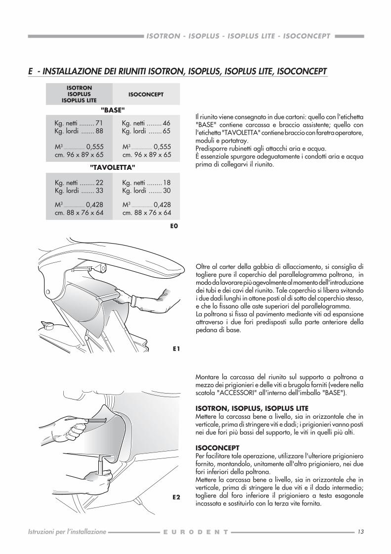
Oltre al carter della gabbia di allacciamento, si consiglia ditogliere pure il coperchio del parallelogramma poltrona, inmodo da lavorare più agevolmente al momento dell'introduzionedei tubi e dei cavi del riunito. Tale coperchio si libera svitandoi due dadi lunghi in ottone posti al di sotto del coperchio stesso,e che lo fissano alle aste superiori del parallelogramma.La poltrona si fissa al pavimento mediante viti ad espansioneattraverso i due fori predisposti sulla parte anteriore dellapedana di base.
Montare la carcassa del riunito sul supporto a poltrona amezzo dei prigionieri e delle viti a brugola forniti (vedere nellascatola "ACCESSORI" all'interno dell'imballo "BASE").
ISOTRON, ISOPLUS, ISOPLUS LITEMettere la carcassa bene a livello, sia in orizzontale che inverticale, prima di stringere viti e dadi; i prigionieri vanno postinei due fori più bassi del supporto, le viti in quelli più alti.
ISOCONCEPTPer facilitare tale operazione, utilizzare l'ulteriore prigionierofornito, montandolo, unitamente all'altro prigioniero, nei duefori inferiori della poltrona.Mettere la carcassa bene a livello, sia in orizzontale che inverticale, prima di stringere le due viti e il dado intermedio;togliere dal foro inferiore il prigioniero a testa esagonaleincassata e sostituirlo con la terza vite fornita.
M3 ................... 0,555cm. 96 x 89 x 65
Kg. netti ........ 22Kg. lordi ....... 33
M3 ................... 0,428cm. 88 x 76 x 64
Il riunito viene consegnato in due cartoni: quello con l'etichetta"BASE" contiene carcassa e braccio assistente; quello conl'etichetta "TAVOLETTA" contiene braccio con faretra operatore,moduli e portatray.Predisporre rubinetti agli attacchi aria e acqua.È essenziale spurgare adeguatamente i condotti aria e acquaprima di collegarvi il riunito.
E - INSTALLAZIONE DEI RIUNITI ISOTRON, ISOPLUS, ISOPLUS LITE, ISOCONCEPT
Kg. netti ........ 71Kg. lordi ....... 88
M3 ................... 0,555cm. 96 x 89 x 65
ISOTRONISOPLUS
ISOPLUS LITEISOCONCEPT
M3 ................... 0,428cm. 88 x 76 x 64
"BASE"
"TAVOLETTA"
Kg. netti ........ 46Kg. lordi .......65
Kg. netti ........ 18Kg. lordi ....... 30

14
ISOTRON - ISOPLUS - ISOPLUS LITE - ISOCONCEPT
Istruzioni per l’installazione
E3
Introdurre nel foro sagomato sul braccio del parallelogrammapoltrona prima di tutto il tubo di aspirazione, poi i cavi elettrici,avvolti mediante nastro ai tubi in rilsan (verde e bianco); infinefar passare il tubo di scarico. Fare arrivare tutti i tubi e i cavifino alla gabbia di allacciamento.
ISOTRON, ISOPLUS, ISOPLUS LITENelle scatole di accessori si trovano il pedale, le cannuleaspirazione con relativi tubi, l'eventuale (se ordinata) siringaassistente con forcina a clip, quattro viti, un cavetto grigio peril collegamento fra cavo del pedale e gabbia di allacciamento,elettrovalvole generali acqua e aria, connettori elettrici disicurezza.Il cavetto possiede un capo a spinotto quadrato e uno a zoccolocircolare: spingere il primo attraverso il tubo che, dentro lapedana di base, collega l'esterno alla gabbia di allacciamento,e tirarlo sino a che la cornice dello zoccolo circolare aderiscea quella del tubo. Stringere le quattro vitine autofilettanti nei foridella cornice, fino a che siano completamente entrate nelpoliuretano e blocchino lo zoccolo del cavetto.
E4
ISOCONCEPTNelle scatole di accessori si trovano il pedale, le cannuleaspirazione con relativi tubi, l'eventuale (se ordinata) siringaassistente con forcina a clip, quattro viti, 2 raccordi, il rubinettogenerale acqua e aria, connettori elettrici di sicurezza eplatina-ponte.Far passare cavi elettrici e tubi della pedaliera attraverso il tuboche, dentro la pedana di base, collega l'esterno alla gabbia diallacciamento, ed appoggiare la flangia del cordone dellapedaliera a quella del tubo. Stringere le quattro vitineautofilettanti nei fori della cornice, fino a che sianocompletamente entrate nel poliuretano e blocchino la flangia.
E5

15
ISOTRON - ISOPLUS - ISOPLUS LITE - ISOCONCEPT
Istruzioni per l’installazione
Montare il braccio tavoletta del riunito (facendo prima passareil cavetto e i tubi entro la carcassa), e bloccare l'escursione delbraccio inserendo vite e dado (forniti tra gli accessori) nel forodel perno.
ISOTRON, ISOPLUS, ISOPLUS LITESulla platina di bassa tensione, innestare il cavetto del braccionella CN1 (in alto a sinistra).Il tubo bianco va collegato al raccordo rapido per l'aria aimoduli, situato a destra dei riduttori d'aria; il tubo rosso (soloISOTRON) va al raccordo sul coperchio del collettored'amalgama, e quello verde al gruppo di distribuzionedell'acqua (per bicchiere, siringa assistente e moduli) collocatosul lato poltrona.
ISOCONCEPTSulla platina, innestare il cavetto del braccio nella X1 e X2 (inalto a sinistra).Il tubo bianco 3/5 va collegato al raccordo per l'ariapermanente, situato a destra del riduttore d'aria; il tubo verdeva collegato al gruppo di distribuzione dell'acqua. I restantitubi vanno collegati ai rispettivi raccordi passanti situati sulgruppo idrico.
N.B. Durante il montaggio rispettare sempre le corrispondenzedei colori dei tubi.
E6
E7
E8
Fissare il vassoio portatray sotto la tavoletta portamoduli (saràpiù semplice con una chiave di 17 a tubo o a bussola).
Introdurre cavo e perno del braccio assistente nella sederelativa (sul fondo della carcassa, lato poltrona), e bloccare ilperno con l'anello elastico seeger e la sua rondella distanzialedi rinforzo.Far passare il cavo nella carcassa fino ad innestarlo nella presaC5 (per ISOTRON) o C2 (per ISOPLUS e ISOPLUS LITE) dellaplatina di bassa tensione. Oppure nel caso di ISOCONCEPTpresa X5 della platina carcassa.N.B. Fare attenzione che il cavo non resti penzolantesotto la carcassa.Introdurre il gruppo di frizionamento nel foro a lato della sededel perno e stringere la vite a misura.
16
ISOTRON - ISOPLUS - ISOPLUS LITE - ISOCONCEPT
Istruzioni per l’installazione
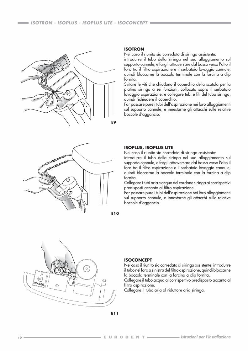
E9
ISOTRONNel caso il riunito sia corredato di siringa assistente:introdurre il tubo della siringa nel suo alloggiamento sulsupporto cannule, e fargli attraversare dal basso verso l'alto ilforo tra il filtro aspirazione e il serbatoio lavaggio cannule,quindi bloccarne la boccola terminale con la forcina a clipfornita.Svitare le viti che chiudono il coperchio della scatola per laplatina siringa a sei funzioni, collocata sopra il serbatoiolavaggio aspirazione, e collegare tubi e fili del tubo siringa,quindi richiudere il coperchio.Far passare pure i tubi dell'aspirazione nei loro alloggiamentisul supporto cannule, e innestarne gli attacchi sulle relativeboccole d'aggancio.
E10
ISOPLUS, ISOPLUS LITENel caso il riunito sia corredato di siringa assistente:introdurre il tubo della siringa nel suo alloggiamento sulsupporto cannule, e fargli attraversare dal basso verso l'alto ilforo tra il filtro aspirazione e il serbatoio lavaggio cannule,quindi bloccarne la boccola terminale con la forcina a clipfornita.Collegare i tubi aria e acqua del cordone siringa ai corrispettivipredisposti accanto al filtro aspirazione.Far passare pure i tubi dell'aspirazione nei loro alloggiamentisul supporto cannule, e innestarne gli attacchi sulle relativeboccole d'aggancio.
E11
ISOCONCEPTNel caso il riunito sia corredato di siringa assistente: introdurreil tubo nel foro a sinistra del filtro aspirazione, quindi bloccarnela boccola terminale con la forcina a clip fornita.Collegare il tubo acqua al corrispettivo predisposto accanto alfiltro aspirazione.Collegare il tubo aria al riduttore aria siringa.
17
ISOTRON - ISOPLUS - ISOPLUS LITE - ISOCONCEPT
Istruzioni per l’installazione
E12
E13
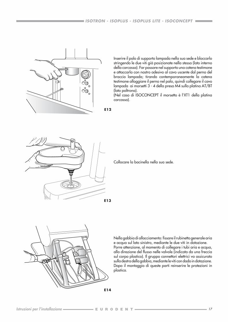
Nella gabbia di allacciamento: fissare il rubinetto generale ariae acqua sul lato sinistro, mediante le due viti in dotazione.Porre attenzione, al momento di collegare i tubi aria e acqua,alla direzione del flusso nelle valvole (indicata da una frecciasul corpo plastico). Il gruppo connettori elettrici va assicuratosulla destra della gabbia, mediante le viti con dado in dotazione.Dopo il montaggio di queste parti reinserire le protezioni inplastica.
Inserire il palo di supporto lampada nella sua sede e bloccarlostringendo le due viti già posizionate nella stessa (lato internodella carcassa). Far passare nel supporto una catena testimonee attaccarla con nastro adesivo al cavo uscente dal perno delbraccio lampada; tirando contemporaneamente la catenatestimone alloggiare il perno nel palo, quindi collegare il cavolampada ai morsetti 3 - 4 della presa M4 sulla platina AT/BT(lato poltrona).(Nel caso di ISOCONCEPT il morsetto è l’XT1 della platinacarcassa).
E14
Collocare la bacinella nella sua sede.

18
ISOTRON - ISOPLUS - ISOPLUS LITE - ISOCONCEPT
Istruzioni per l’installazione
F - COLLEGAMENTI ELETTRICI ED ELETTROPNEUMATICI
ISOTRON, ISOPLUS, ISOPLUS LITECollegamenti elettrici nella gabbia di allacciamento: nella gabbia arrivano diversi cavi, ossia quello grigio di raccordo tracavo pedale e gabbia il cavo nero a 4 fili per comunicazione seriale col riunito, e il cavo bianco a tre fili (marrone, blu, giallo-verde) dell'alimentazione alla poltrona.E ancora, in arrivo dal riunito:un cavo nero d'alimentazione a 3 fili (blu, marrone, giallo-verde), un cavo bianco a 3 fili (blu, marrone, giallo-verde), un altrobianco (2 fili) ed un altro nero (2 fili), un grigio per collegamento pedale riunito, un nero a 4 fili per comunicazione serialecon la poltrona e infine un nero con due faston.I connettori di sicurezza (un nero e un bianco) dispongono di dieci morsetti.
I due faston vanno all'elettrovalvola generale aria ed acqua (24V).Collegare il cavo (1) di raccordo pedale al cavo pedale riunito (2).Collegare il cavo (3) nero a 4 fili x seriale della poltrona al cavo (4) nero a 4 fili x seriale del riunito.I fili del cavetto bianco (per la chiusura del circuito di controllo della pompa d'aspirazione) vanno collegati ai primi duemorsetti marroni, mentre agli altri due vanno fissati i fili del cavetto nero (chiusura circuito per chiamata assistente o altroservizio).
cavetto nero
cavetto bianco
P. C
cavo nero
bianco a poltrona rete 220Vac
riunito
cavo bianco a riunito
cavo a 4 fili x serialealla poltrona
F1
3
4
1
2cavo a 4 fili x seriale
al riunito
cavo di raccordopedale
cavo pedale alriunito

19
ISOTRON - ISOPLUS - ISOPLUS LITE - ISOCONCEPT
Istruzioni per l’installazione
I tre fili del cavo bianco grosso vanno ai morsetti del connettore bianco (blu al morsetto N, marrone a quello L, giallo-verdea quello di massa); sui corrispettivi, vanno collegati i fili del cavo bianco di alimentazione poltrona, sempre secondo le relazionidi colore con le indicazioni L, N e massa. Lasciare il cavo nero del pedale poltrona collegato al cavo nero comandi poltrona.Infine, i fili del cavo nero di alimentazione proveniente dal riunito vanno collegati sui tre morsetti del connettore nero (blu suN, marrone su L e giallo-verde su massa); sui corrispettivi, vanno fissati i fili del cavo proveniente dalla rete (220 Vac).Proteggere anche le connessioni volanti con la protezione in plastica in dotazione nella scatola accessori.
Riposizionare il coperchio del parallelogramma e fissarlo tramite i due dadi-tiranti in ottone, quindi chiudere la gabbia diallacciamento col suo carter. Montare i due pannelli laterali della carcassa riunito, e fermare il cavetto con capocorda allavite sul pannello esterno.
220 V 220 V
N L 1 B 4 S 3 T 2 T 1 N L 1
F2
RL aspi RL chiamatariunito riunito
Bianco White Blanc Weiß Blanco Nero Black Noir Schwarz Negro
AspirazioneSuctionAspirationAbsaugungAspiración
terra poltronacircuitocampanello
bianco poltrona centralinapompa
rete
24 V max1 A max
24 V max1 A max
20
ISOTRON - ISOPLUS - ISOPLUS LITE - ISOCONCEPT
Istruzioni per l’installazione
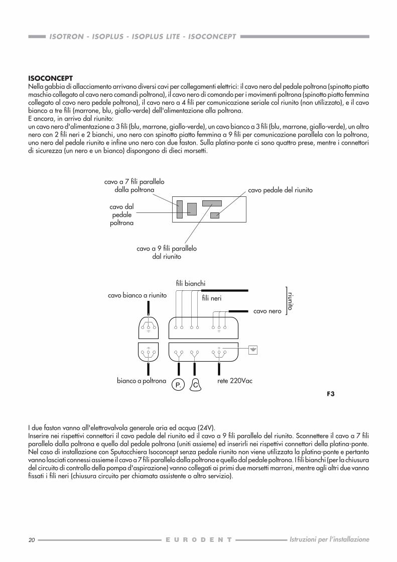
I due faston vanno all'elettrovalvola generale aria ed acqua (24V).Inserire nei rispettivi connettori il cavo pedale del riunito ed il cavo a 9 fili parallelo del riunito. Sconnettere il cavo a 7 filiparallelo dalla poltrona e quello dal pedale poltrona (uniti assieme) ed inserirli nei rispettivi connettori della platina-ponte.Nel caso di installazione con Sputacchiera Isoconcept senza pedale riunito non viene utilizzata la platina-ponte e pertantovanno lasciati connessi assieme il cavo a 7 fili parallelo dalla poltrona e quello dal pedale poltrona. I fili bianchi (per la chiusuradel circuito di controllo della pompa d'aspirazione) vanno collegati ai primi due morsetti marroni, mentre agli altri due vannofissati i fili neri (chiusura circuito per chiamata assistente o altro servizio).
ISOCONCEPTNella gabbia di allacciamento arrivano diversi cavi per collegamenti elettrici: il cavo nero del pedale poltrona (spinotto piattomaschio collegato al cavo nero comandi poltrona), il cavo nero di comando per i movimenti poltrona (spinotto piatto femminacollegato al cavo nero pedale poltrona), il cavo nero a 4 fili per comunicazione seriale col riunito (non utilizzato), e il cavobianco a tre fili (marrone, blu, giallo-verde) dell'alimentazione alla poltrona.E ancora, in arrivo dal riunito:un cavo nero d'alimentazione a 3 fili (blu, marrone, giallo-verde), un cavo bianco a 3 fili (blu, marrone, giallo-verde), un altronero con 2 fili neri e 2 bianchi, uno nero con spinotto piatto femmina a 9 fili per comunicazione parallela con la poltrona,uno nero del pedale riunito e infine uno nero con due faston. Sulla platina-ponte ci sono quattro prese, mentre i connettoridi sicurezza (un nero e un bianco) dispongono di dieci morsetti.
fili bianchi
cavo nero
bianco a poltrona rete 220Vac
riunito
cavo pedale del riunito
cavo bianco a riunito
cavo a 7 fili parallelodalla poltrona
cavo dalpedale
poltrona
cavo a 9 fili parallelodal riunito
F3
fili neri
P. C

21
ISOTRON - ISOPLUS - ISOPLUS LITE - ISOCONCEPT
Istruzioni per l’installazione
I tre fili del cavo bianco grosso vanno ai morsetti del connettore bianco (blu al morsetto N, marrone a quello L, giallo-verdea quello di massa); sui corrispettivi, vanno collegati i fili del cavo bianco di alimentazione poltrona, sempre secondo le relazionidi colore con le indicazioni L, N e massa. Lasciare il cavo nero del pedale poltrona collegato al cavo nero comandi poltrona.Infine, i fili del cavo nero di alimentazione proveniente dal riunito vanno collegati sui tre morsetti del connettore nero (blu suN, marrone su L e giallo-verde su massa); sui corrispettivi, vanno fissati i fili del cavo proveniente dalla rete (220 Vac).Proteggere anche le connessioni volanti con la protezione in plastica in dotazione nella scatola accessori.
220 V 220 V
N L 1 B 4 S 3 T 2 T 1 N L 1 F4
RL aspi RL chiamatariunito riunito
Bianco White Blanc Weiß Blanco Nero Black Noir Schwarz Negro
AspirazioneSuctionAspirationAbsaugungAspiración
terra poltronacircuitocampanello
bianco poltrona centralinapompa
rete
24 V max1 A max
24 V max1 A max
Collegare i tubi pedaliera con i relativi raccordi, rispettando levarie corrispondenze secondo i colori dei tubi.Riposizionare il coperchio del parallelogramma e fissarlotramite i due dadi-tiranti in ottone, quindi chiudere la gabbiadi allacciamento col suo carter. Montare i due pannelli lateralidella carcassa riunito, e fermare il cavetto con capocorda allavite sul pannello esterno.
F5
22
ISOTRON - ISOPLUS - ISOPLUS LITE - ISOCONCEPT
Istruzioni per l’installazione
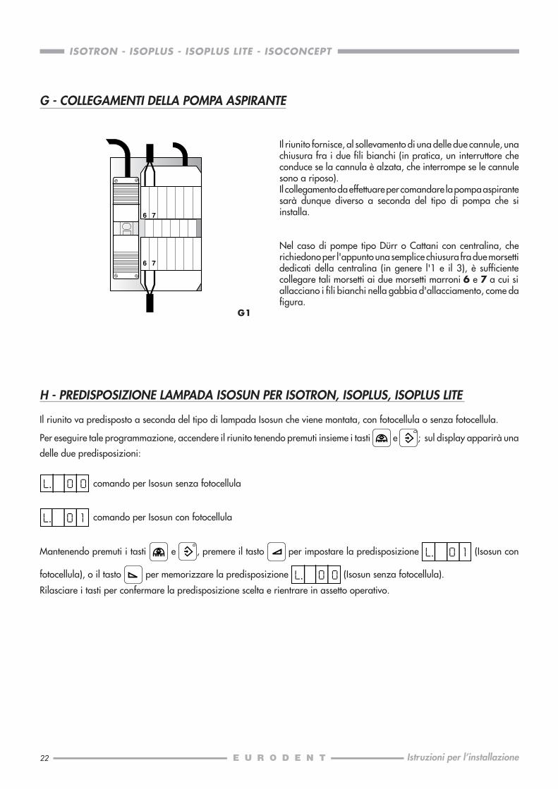
Il riunito fornisce, al sollevamento di una delle due cannule, unachiusura fra i due fili bianchi (in pratica, un interruttore checonduce se la cannula è alzata, che interrompe se le cannulesono a riposo).Il collegamento da effettuare per comandare la pompa aspirantesarà dunque diverso a seconda del tipo di pompa che siinstalla.
Nel caso di pompe tipo Dürr o Cattani con centralina, cherichiedono per l'appunto una semplice chiusura fra due morsettidedicati della centralina (in genere l'1 e il 3), è sufficientecollegare tali morsetti ai due morsetti marroni 6 e 7 a cui siallacciano i fili bianchi nella gabbia d'allacciamento, come dafigura.
6 7
6 7
G - COLLEGAMENTI DELLA POMPA ASPIRANTE
H - PREDISPOSIZIONE LAMPADA ISOSUN PER ISOTRON, ISOPLUS, ISOPLUS LITE
Il riunito va predisposto a seconda del tipo di lampada Isosun che viene montata, con fotocellula o senza fotocellula.
Per eseguire tale programmazione, accendere il riunito tenendo premuti insieme i tasti e ; sul display apparirà una
delle due predisposizioni:
comando per Isosun senza fotocellula
comando per Isosun con fotocellula
Mantenendo premuti i tasti e , premere il tasto per impostare la predisposizione (Isosun con
fotocellula), o il tasto per memorizzare la predisposizione (Isosun senza fotocellula).
Rilasciare i tasti per confermare la predisposizione scelta e rientrare in assetto operativo.
G1
23
ISOTRON - ISOPLUS - ISOPLUS LITE - ISOCONCEPT
Istruzioni per l’installazione
I2
FUNZIONI DEI TRIMMER
1 - Tensione luce fredda2 - Tensione minima al motore3 - Tensione massima al motore4 - Compensazione del motore
1
34
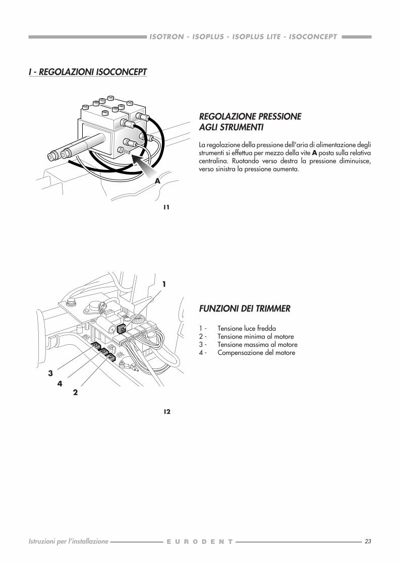
REGOLAZIONE PRESSIONEAGLI STRUMENTI
La regolazione della pressione dell'aria di alimentazione deglistrumenti si effettua per mezzo della vite A posta sulla relativacentralina. Ruotando verso destra la pressione diminuisce,verso sinistra la pressione aumenta.
I1
I - REGOLAZIONI ISOCONCEPT
A
2

25
ISOTRON - ISOPLUS - ISOPLUS LITE - ISOCONCEPT
Installation instructions
SERVICE REQUIREMENT .......................................................................................... 26DECLARATION OF RESPONSIBILITY ......................................................................... 26ARRANGEMENT ..................................................................................................... 27
A PACKAGE OF THE ISORAMA AND ISO CHAIRS ................................................... 28TRANSPORT AND INSTALLATION ....................................................................... 29
B INSTALLING THE ISORAMA CHAIR ...................................................................... 30PREPARATION ................................................................................................... 30RELEASING THE BACKREST ................................................................................ 30FASTENING THE BACKREST ................................................................................ 30OPERATING TEST ............................................................................................... 31BACKREST PAD ..................................................................................................31SEAT PAD .......................................................................................................... 32
C INSTALLING THE ISO CHAIR ................................................................................33BACKREST ......................................................................................................... 33BACKREST UPHOLSTERY ..................................................................................... 33SEAT UPHOLSTERY ............................................................................................. 34FITTING OF THE ARMRESTS ................................................................................ 34
D HEADREST FOR THE ISORAMA AND ISO CHAIRS .................................................36
E INSTALLING THE ISOTRON,ISOPLUS, ISOPLUS LITE, ISOCONCEPT DENTAL UNITS .......................................... 37
F ELECTRICAL AND ELECTROPNEUMATICAL CONNECTIONS .................................... 42ISOTRON, ISOPLUS, ISOPLUS LITE ....................................................................... 42ISOCONCEPT .................................................................................................... 44
G CONNECTING THE SUCTION PUMP .................................................................... 46
H ARRANGEMENT OF ISOSUN LAMP FOR ISOTRON, ISOPLUS, ISOPLUS LITE ........... 46
I ISOCONCEPT ADJUSTEMENTS ............................................................................47PRESSURE ADJUSTMENT TO INSTRUMENTS ........................................................ 47TRIMMER FUNCTIONS ........................................................................................ 47
INDEX Page

26
ISOTRON - ISOPLUS - ISOPLUS LITE - ISOCONCEPT
Installation instructions
SERVICE REQUIREMENT
The unit to be installed is CLASS I, with attached parts of TYPE B ,
with electronic bistoury or electrobistoury with attached part of TYPE BF (ISOTRON, ISOPLUS, ISOPLUS LITE only)
Classification headings (EN60 601-1):5.3 Common equipments (equipments with no waterproof casing);5.5 Equipments which cannot be used in presence of an anaesthetic mixture inflammable by air or by oxygen or by nitrous
oxide;5.6 Equipments for continuous working with intermittent load.
Power: 220 V / 50 Hz / 1350 VA (550 VA only unit) for ISOTRON, ISOPLUS, ISOPLUS LITE.220 V / 50 Hz / 1000 VA (200 VA only unit) for ISOCONCEPT.
Operating system: continuous, with intermitting loadMax. lifting capacity: 120 kg (dental unit and lamp excluded)
The floor must be in accordance with DIN 1055 B1.3 and DIN 18560 T1 regulations.
It is necessary to instal an outer bipolar main switch to wall, in compliance with the law and with the following electriccharacteristics: 250 V / 10 A for disconnecting the unit from the main feed in case of intervention or inspection in it.
The electrical system must be in accordance with IEC regulations 64.4, and made up of difference protective conductors (withindex < 30 mA) at 16A/250V.Moreover, earthing must conform to the art. 3.2.01 of the regulations mentioned above.
Water pressure at the unit inlet must range from 1,8 to 3,0 bar. The pipes must be capable to supply at least 5 l/minute ofwater flow rate.Water characteristics must conform to DIN 1988 rules, with a hardness gradient ≤ 8° dH (corresponding to 1,432 mmol/lit).We recommend installing a pressure reducing tap at the water hose outlet (preferably of 15 mm Ø).
The air pressure provided by the compressor must range from 5,0 to 7,0 bar. Use a dry compressor, with air output of 60lit/min. at 5 bar. We recommend installing a tap at the hose outlet (preferably of 15 mm Ø).
The diameter of the emptying hose must be 40 mm, and 32 mm at its inlet; moreover the descent gradient must be at least1 cm/mt, and the bend angle should not be less than 135°.
The diameter of the suction pipe must be approx. 32/40 mm. We recommend following the instructions provided by the suctionpump’s manufacturer.
All arrangements must be carried out according to the indications provided on the following page and consulting the full scaleinstallation plan (code 633580010) attached to each dental unit.
Please refer to Spare Parts catalogue and apply to EURODENT for further information about what is not included in it.
EURODENT accepts responsibility for the equipment safety and reliability if and only if:- installation, assembly, extension, adjustment and repair operations have been carried out by authorized people.- the general and electric installation of the room complies with the above written requirements.- the equipment has been installed in compliance with the “INSTALLATION INSTRUCTIONS”.- the equipment is used in compliance with the “OPERATOR'S HANDBOOK”.
0051 The apparatus comply with the fundamental requirements of EC Directive 93/42.
Protection earth
Warning, see enclosed documents
27
ISOTRON - ISOPLUS - ISOPLUS LITE - ISOCONCEPT
Installation instructions
ARRANGEMENT
..
.....
5060
175
E
A
A 3/8"G
20
B
C D
35
295
150
80
40
40 30
40
B
C
3/8"G
20
25
ø 32ø
40
D
E
25
500
ø 32
ø 4
0
Hole for fasteningto floor
Hole for fasteningto floor
ISOSUN
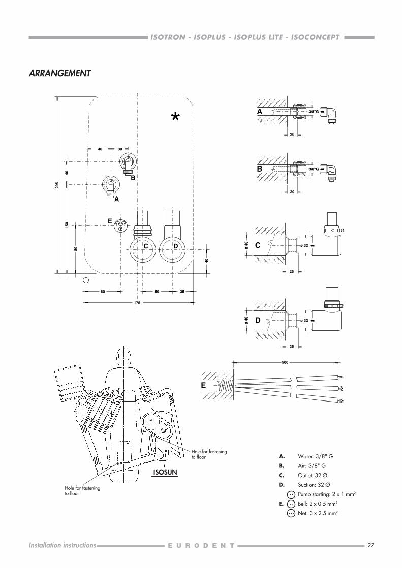
A. Water: 3/8" G
B. Air: 3/8" G
C. Outlet: 32 Ø
D. Suction: 32 Ø
Pump starting: 2 x 1 mm2
E. Bell: 2 x 0.5 mm2
Net: 3 x 2.5 mm2

28
ISOTRON - ISOPLUS - ISOPLUS LITE - ISOCONCEPT
Installation instructions
A0
1
ALTO
BOLOGNA
ITALYCOD OPZIONEMATR.
Net weight ......131Gross weight .....152.................. 0,6 m3
cm. 125 x 69 x 70
2
ALTO
BOLOGNA
ITALYCOLORE OOPZIONE
TAPPEZZERIA
CODICEMATR.
ISORAMANet weight ......116Gross weight .....137.................. 0,6 m3
cm. 125 x 69 x 70
ISO
Net weight ........ 13Gross weight .......18.................. 0,2 m3
cm. 115 x 65 x 25
ISORAMANet weight ........ 10Gross weight .......16................ 0,12 m3
cm. 93 x 51 x 25
ISO
ISORAMA
ISO
A - PACKAGE OF THE ISORAMA AND ISO CHAIRS
The special packing system of these chairs has been thought in order to reduce its overall dimension.
For such a reason, the body of the chair is placed into the packing case 1 with the backrest bent over the seat (see figureA0), whereas upholstery, seat, backrest and headrest are contained into the packing case 2 .
When removing the chair from the packing case, cut the box 1 along the dotted line.

29
ISOTRON - ISOPLUS - ISOPLUS LITE - ISOCONCEPT
Installation instructions
A1
A2
B
AA
B
TRANSPORT AND INSTALLATION
Remove the chair from its packing and, before moving it, take the covering guard of the connecting box off, so as to makethe seizing of the chair and transport easier. Do not lift the chair by seizing the pantograph head or the legrest.Position the chair so as to place all couplings inside the connecting box (placed at the bottom of the chair parallelogram). Makesure that you do not inadvertently squash or tear the electrical cables of the chair when slipping it on the floor. Pay specialcare to the cable of the foot-control.Check the level evenness of the floor with respect to the bearing surface of the base. Fasten the chair by fitting the expansionstoppers type Fischer (supplied with the accessories) into the two housings (see figure A1).M6 expansion bolts and proper spanner are supplied with the chair.The hole in the floor must be at least 115-mm deep.As regards installation, we advise connecting temporarily the chair to the main supply in order to have it lifted simply byoperating the foot-control.BE CAREFUL! Connect the backrest to the motor and to the Trendelenburg device before making it perform any movement.When the chair reaches the height right for operating comfortably, cut out voltage.
IMPORTANT: if assembly does NOT allow connection insidethe chair base box, you can use the front base frame as outletwindow, by removing the baffle plugs with a cutter.
Bolt M6 x 140
Expansion nut
Long spacer
Bolt M6 x 110
Short spacer
Expansion nut
30
ISOTRON - ISOPLUS - ISOPLUS LITE - ISOCONCEPT
Installation instructions
B1
B2
B - INSTALLING THE ISORAMA CHAIR
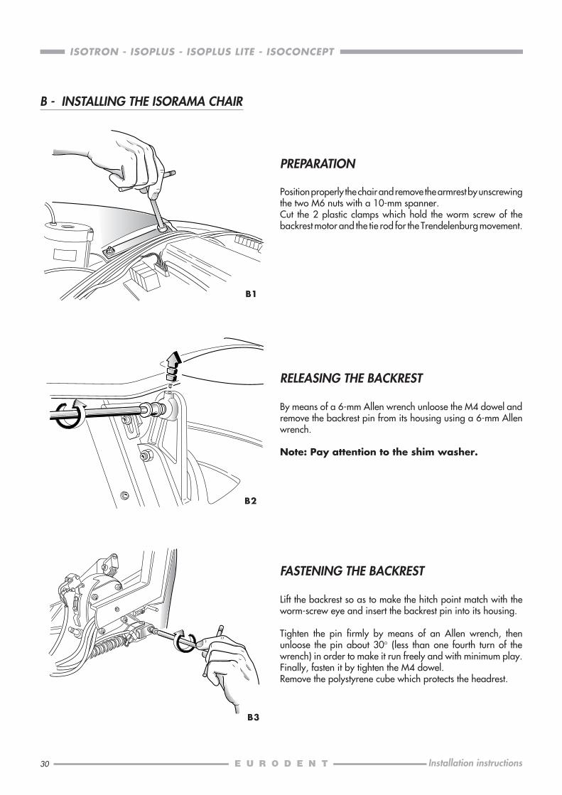
PREPARATION
Position properly the chair and remove the armrest by unscrewingthe two M6 nuts with a 10-mm spanner.Cut the 2 plastic clamps which hold the worm screw of thebackrest motor and the tie rod for the Trendelenburg movement.
RELEASING THE BACKREST
By means of a 6-mm Allen wrench unloose the M4 dowel andremove the backrest pin from its housing using a 6-mm Allenwrench.
Note: Pay attention to the shim washer.
FASTENING THE BACKREST
Lift the backrest so as to make the hitch point match with theworm-screw eye and insert the backrest pin into its housing.
Tighten the pin firmly by means of an Allen wrench, thenunloose the pin about 30° (less than one fourth turn of thewrench) in order to make it run freely and with minimum play.Finally, fasten it by tighten the M4 dowel.Remove the polystyrene cube which protects the headrest.
B3

31
ISOTRON - ISOPLUS - ISOPLUS LITE - ISOCONCEPT
Installation instructions
B4
B6
B5
BACKREST PAD
Position upholstery higher than backrest. Then, slide itdownwards, in order to secure it properly and firmly to the threefastening screws, as shown in figure.
Fasten upholstery by the T-clamp, and press it against the twoupholstery tags, as shown in figure.
Relocate the armrest.
OPERATING TEST
Now, proceed to fit the tie rod operating the Trendelenburgmovement.By using a 13-mm spanner remove the nut, then insert the tierod eye and lock the rod again by the proper nut.Supply voltage to the chair and perform some trial movementsin order to ascertain that the stop microswitches work properly.Finally, mount upholstery.
32
ISOTRON - ISOPLUS - ISOPLUS LITE - ISOCONCEPT
Installation instructions
B8
B10
B7
B9
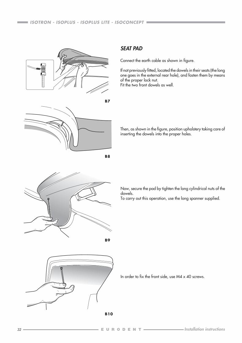
SEAT PAD
Connect the earth cable as shown in figure.
If not previously fitted, located the dowels in their seats (the longone goes in the external rear hole), and fasten them by meansof the proper lock nut.Fit the two front dowels as well.
Then, as shown in the figure, position upholstery taking care ofinserting the dowels into the proper holes.
Now, secure the pad by tighten the long cylindrical nuts of thedowels.To carry out this operation, use the long spanner supplied.
In order to fix the front side, use M4 x 40 screws.
33
ISOTRON - ISOPLUS - ISOPLUS LITE - ISOCONCEPT
Installation instructions
C2
C3
C1
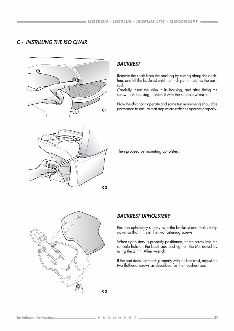
BACKREST
Remove the chair from the packing by cutting along the dash-line, and lift the backrest until the hitch point matches the pushrod.Carefully insert the shim in its housing, and after fitting thescrew in its housing, tighten it with the suitable wrench.
Now the chair can operate and some test movements should beperformed to ensure that stop microswitches operate properly.
Then proceed by mounting upholstery.
BACKREST UPHOLSTERY
Position upholstery slightly over the backrest and make it slipdown so that it fits in the two fastening screws.
When upholstery is properly positioned, fit the screw into thesuitable hole on the back side and tighten the M4 dowel byusing the 2 mm Allen wrench.
If the pad does not match properly with the backrest, adjust thetwo flathead screws as described for the headrest pad.
C - INSTALLING THE ISO CHAIR
34
ISOTRON - ISOPLUS - ISOPLUS LITE - ISOCONCEPT
Installation instructions
C4
C5
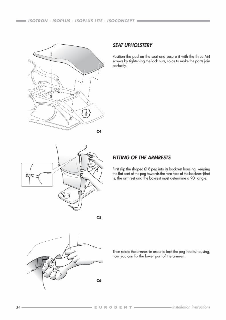
Then rotate the armrest in order to lock the peg into its housing,now you can fix the lower part of the armrest.
C6
SEAT UPHOLSTERY
Position the pad on the seat and secure it with the three M4screws by tightening the lock nuts, so as to make the parts joinperfectly.
FITTING OF THE ARMRESTS
First slip the shaped Ø 8 peg into its backrest housing, keepingthe flat part of the peg towards the fore face of the backrest (thatis, the armrest and the bakrest must determine a 90° angle.
35
ISOTRON - ISOPLUS - ISOPLUS LITE - ISOCONCEPT
Installation instructions
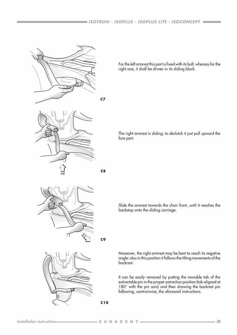
For the left armrest this part is fixed with its bolt, whereas for theright one, it shall be driven in its sliding block.
C7
The right armrest is sliding: to declutch it just pull upward thefore part.
C8
C9
C10
Slide the armrest towards the chair front, until it reaches thebackstop onto the sliding carriage.
Moreover, the right armrest may be bent to reach its negativeangle: also in this position it follows the tilting movements of thebackrest.
It can be easily removed by putting the movable tab of theextractable pin in the proper extraction position (tab aligned at180° with the pin axis) and then drawing the backrest pinfollowing, contrariwise, the aforesaid instructions.
36
ISOTRON - ISOPLUS - ISOPLUS LITE - ISOCONCEPT
Installation instructions
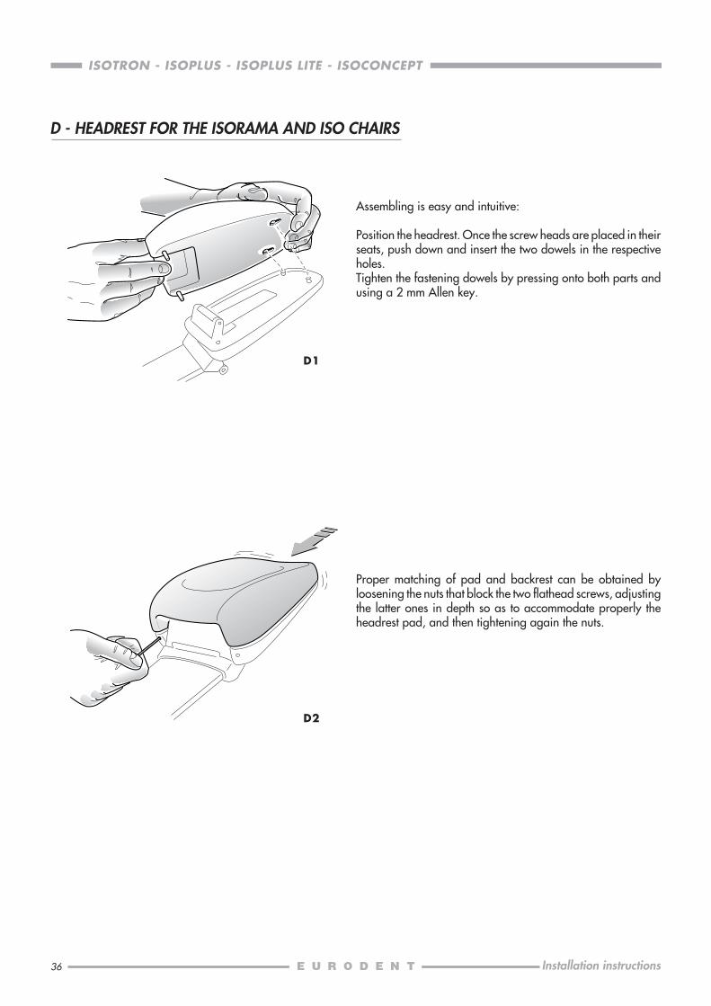
Assembling is easy and intuitive:
Position the headrest. Once the screw heads are placed in theirseats, push down and insert the two dowels in the respectiveholes.Tighten the fastening dowels by pressing onto both parts andusing a 2 mm Allen key.
Proper matching of pad and backrest can be obtained byloosening the nuts that block the two flathead screws, adjustingthe latter ones in depth so as to accommodate properly theheadrest pad, and then tightening again the nuts.
D2
D - HEADREST FOR THE ISORAMA AND ISO CHAIRS
D1

37
ISOTRON - ISOPLUS - ISOPLUS LITE - ISOCONCEPT
Installation instructions
E0
E1
E2
Now, mount the body of the dental unit on the chair support bymeans of the stud bolts and the socket head screws supplied(placed inside the “ACCESSORY” box, into the packing caselabelled “BASE”).
ISOTRON, ISOPLUS, ISOPLUS LITEBefore fastening screws and nuts, level the body properlyhorizontally and vertically. Please, note that stud bolts shall beinserted into the support lower holes, whereas screws into thehigher ones.
ISOCONCEPTTo make such operation easier, fit the additional Allen-headstud bolt supplied into the second of the two lower holes.Level the body properly (horizontally and vertically) beforetightening the two screws and the middle nut; remove the Allen-head stud bolt from the lower hole and replace it with the thirdscrew supplied.
.......... 0,555 m3
cm. 96 x 89 x 65
Net weight ......22Gross weight ... 33
.......... 0,428 m3
cm. 88 x 76 x 64
E - INSTALLING THE ISOTRON, ISOPLUS, ISOPLUS LITE, ISOCONCEPT DENTAL UNITS
Net weight ...... 71Gross weight ... 88
.......... 0,555 m3
cm. 96 x 89 x 65
ISOTRONISOPLUS
ISOPLUS LITEISOCONCEPT
.......... 0,428 m3
cm. 88 x 76 x 64
"BASE"
"INSTRUMENT TABLE"
Net weight ...... 46Gross weight ... 65
Net weight ......18Gross weight ... 30
In addition to the guard of the connecting box, we recommendthat you remove even the lid of the chair parallelogram, in orderto operate easily when introducing hoses and cables into thedental unit. Remove such mentioned lid by unscrewing the twolong brass nuts which are placed under it and which fasten it tothe upper rods of the parallelogram.The chair shall be fastened to floor by inserting expansion boltsinto the two holes made on the front side of the base footboard.
The dental unit is supplied into two packing cases: the first onelabelled “BASE” contains the body and the assistant arm; thesecond one labelled “INSTRUMENT TABLE” contains the operatorretraction arm, the modules and the tray holder.Provide air and water hose couplings with taps. It is absolutelynecessary to clean out air and water pipes before connectingthe dental unit to them.
38
ISOTRON - ISOPLUS - ISOPLUS LITE - ISOCONCEPT
Installation instructions
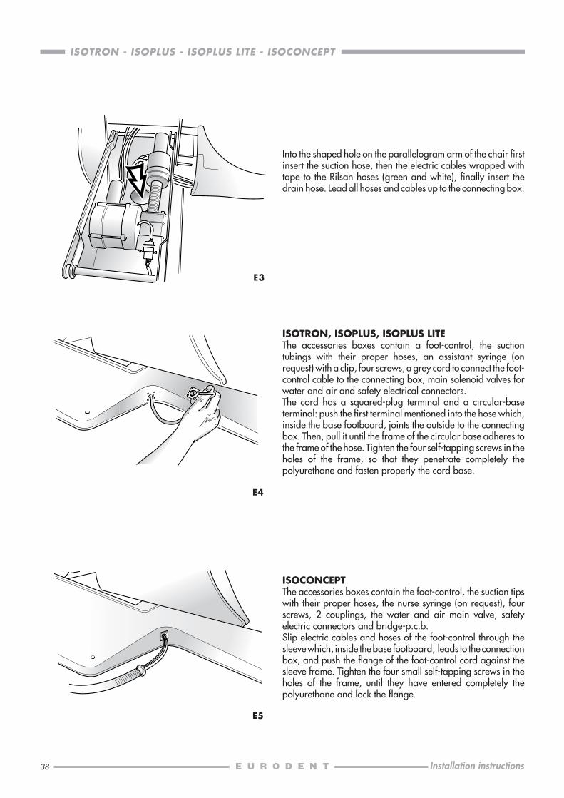
E3
ISOTRON, ISOPLUS, ISOPLUS LITEThe accessories boxes contain a foot-control, the suctiontubings with their proper hoses, an assistant syringe (onrequest) with a clip, four screws, a grey cord to connect the foot-control cable to the connecting box, main solenoid valves forwater and air and safety electrical connectors.The cord has a squared-plug terminal and a circular-baseterminal: push the first terminal mentioned into the hose which,inside the base footboard, joints the outside to the connectingbox. Then, pull it until the frame of the circular base adheres tothe frame of the hose. Tighten the four self-tapping screws in theholes of the frame, so that they penetrate completely thepolyurethane and fasten properly the cord base.
E4
ISOCONCEPTThe accessories boxes contain the foot-control, the suction tipswith their proper hoses, the nurse syringe (on request), fourscrews, 2 couplings, the water and air main valve, safetyelectric connectors and bridge-p.c.b.Slip electric cables and hoses of the foot-control through thesleeve which, inside the base footboard, leads to the connectionbox, and push the flange of the foot-control cord against thesleeve frame. Tighten the four small self-tapping screws in theholes of the frame, until they have entered completely thepolyurethane and lock the flange.
E5
Into the shaped hole on the parallelogram arm of the chair firstinsert the suction hose, then the electric cables wrapped withtape to the Rilsan hoses (green and white), finally insert thedrain hose. Lead all hoses and cables up to the connecting box.

39
ISOTRON - ISOPLUS - ISOPLUS LITE - ISOCONCEPT
Installation instructions
Now, install the instrument table arm of the dental unit (howeverfirst make the cable and hoses run through the body) and blockthe travel of the arm by inserting the screw and the nut (suppliedwith accessories) into the pin hole.
ISOTRON, ISOPLUS, ISOPLUS LITEPlug the arm cord into CN1 (on left top side), on the low-tensionrod. Then, connect the white hose to the quick fitting whichprovides modules with air, placed on the right side of the airreduction units. Moreover, connect the red hose (ISOTRONonly) to the fitting placed on the lid of the amalgam header, andthe green one to the water distribution unit (for tumbler,assistant syringe and modules), placed on the chair side.
ISOCONCEPTPlug the arm cord into X1 and X2 (on left top side), on the p.c.b.Then, connect the white 3/5 hose to the union for permanentair, placed on the right side of the air reduction unit. Moreover,connect the green one to the water distribution unit. The otherpipes should be connected to the proper unions placed on thewater unit.
IMPORTANT: When assembly, always respect thecorrespondences of the pipe colours.
E6
E7
E8
Fasten the tray holder under the module-holder table (to makeit easier, use a 17 socket spanner).
Now, insert the cable and the pin of the assistant arm into theproper housing (at the bottom of the body, on the chair side),and lock the pin with the snap ring and its lock space washer.Make the cable run through the body and plug it in the C5 socket(for ISOTRON) or in the C2 (for ISOPLUS and ISOPLUS LITE),placed on the low-tension p.c.b., or in the X5 socket of the bodyp.c.b. (for ISOCONCEPT).NOTE: ensure that the cable does not hang under the body).Insert the friction unit into the hole beside the pin housing andtighten the screw properly.
40
ISOTRON - ISOPLUS - ISOPLUS LITE - ISOCONCEPT
Installation instructions
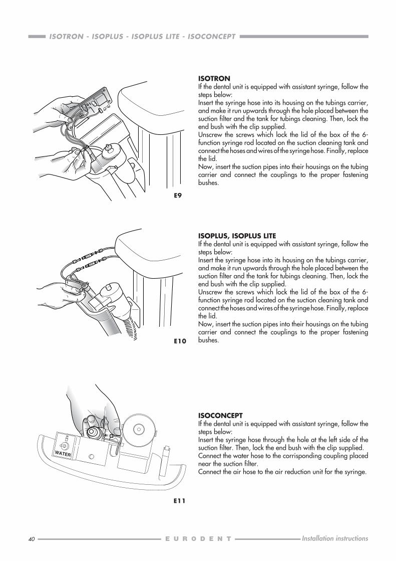
E9
ISOTRONIf the dental unit is equipped with assistant syringe, follow thesteps below:Insert the syringe hose into its housing on the tubings carrier,and make it run upwards through the hole placed between thesuction filter and the tank for tubings cleaning. Then, lock theend bush with the clip supplied.Unscrew the screws which lock the lid of the box of the 6-function syringe rod located on the suction cleaning tank andconnect the hoses and wires of the syringe hose. Finally, replacethe lid.Now, insert the suction pipes into their housings on the tubingcarrier and connect the couplings to the proper fasteningbushes.
E10
ISOPLUS, ISOPLUS LITEIf the dental unit is equipped with assistant syringe, follow thesteps below:Insert the syringe hose into its housing on the tubings carrier,and make it run upwards through the hole placed between thesuction filter and the tank for tubings cleaning. Then, lock theend bush with the clip supplied.Unscrew the screws which lock the lid of the box of the 6-function syringe rod located on the suction cleaning tank andconnect the hoses and wires of the syringe hose. Finally, replacethe lid.Now, insert the suction pipes into their housings on the tubingcarrier and connect the couplings to the proper fasteningbushes.
E11
ISOCONCEPTIf the dental unit is equipped with assistant syringe, follow thesteps below:Insert the syringe hose through the hole at the left side of thesuction filter. Then, lock the end bush with the clip supplied.Connect the water hose to the corrisponding coupling placednear the suction filter.Connect the air hose to the air reduction unit for the syringe.
41
ISOTRON - ISOPLUS - ISOPLUS LITE - ISOCONCEPT
Installation instructions
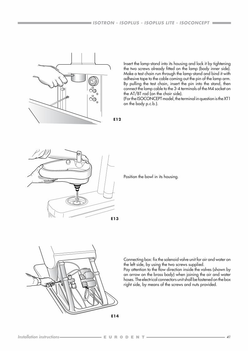
E12
E13
Connecting box: fix the solenoid valve unit for air and water onthe left side, by using the two screws supplied.Pay attention to the flow direction inside the valves (shown byan arrow on the brass body) when joining the air and waterhoses. The electrical connectors unit shall be fastened on the boxright side, by means of the screws and nuts provided.
Insert the lamp-stand into its housing and lock it by tighteningthe two screws already fitted on the lamp (body inner side).Make a test chain run through the lamp-stand and bind it withadhesive tape to the cable coming out the pin of the lamp arm.By pulling the test chain, insert the pin into the stand, thenconnect the lamp cable to the 3-4 terminals of the M4 socket onthe AT/BT rod (on the chair side).(For the ISOCONCEPT model, the terminal in question is the XT1on the body p.c.b.).
E14
Position the bowl in its housing.
42
ISOTRON - ISOPLUS - ISOPLUS LITE - ISOCONCEPT
Installation instructions
F - ELECTRICAL AND ELECTROPNEUMATICAL CONNECTIONS
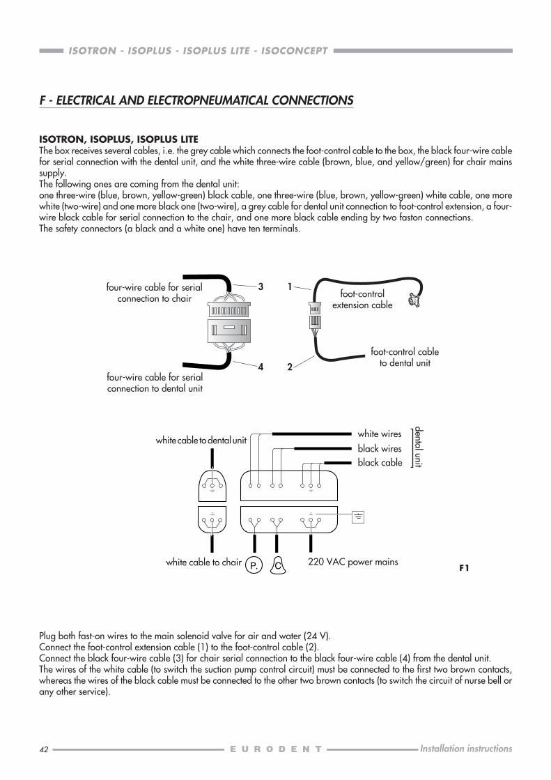
ISOTRON, ISOPLUS, ISOPLUS LITEThe box receives several cables, i.e. the grey cable which connects the foot-control cable to the box, the black four-wire cablefor serial connection with the dental unit, and the white three-wire cable (brown, blue, and yellow/green) for chair mainssupply.The following ones are coming from the dental unit:one three-wire (blue, brown, yellow-green) black cable, one three-wire (blue, brown, yellow-green) white cable, one morewhite (two-wire) and one more black one (two-wire), a grey cable for dental unit connection to foot-control extension, a four-wire black cable for serial connection to the chair, and one more black cable ending by two faston connections.The safety connectors (a black and a white one) have ten terminals.
Plug both fast-on wires to the main solenoid valve for air and water (24 V).Connect the foot-control extension cable (1) to the foot-control cable (2).Connect the black four-wire cable (3) for chair serial connection to the black four-wire cable (4) from the dental unit.The wires of the white cable (to switch the suction pump control circuit) must be connected to the first two brown contacts,whereas the wires of the black cable must be connected to the other two brown contacts (to switch the circuit of nurse bell orany other service).
black wires
white wires
P. C
black cable
white cable to chair 220 VAC power mains
dental unit
white cable to dental unit
four-wire cable for serialconnection to chair
F1
3
4
1
2four-wire cable for serialconnection to dental unit
foot-controlextension cable
foot-control cableto dental unit
43
ISOTRON - ISOPLUS - ISOPLUS LITE - ISOCONCEPT
Installation instructions
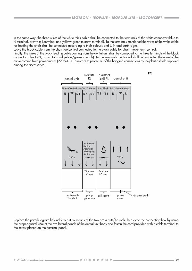
In the same way, the three wires of the white thick cable shall be connected to the terminals of the white connector (blue toN terminal, brown to L terminal and yellow/green to earth terminal). To the terminals mentioned the wires of the white cablefor feeding the chair shall be connected according to their colours and L, N and earth signs.Leave the black cable from the chair footcontrol connected to the black cable for chair movements control.Finally, the wires of the black feeding cable coming from the dental unit shall be connected to the three terminals of the blackconnector (blue to N, brown to L and yellow/green to earth). To the terminals mentioned shall be connected the wires of thecable coming from power mains (220 VAC). Take care to protect all of the hanging connections by the plastic shield suppliedamong the accessories.
Replace the parallelogram lid and fasten it by means of the two brass nuts/tie rods, then close the connecting box by usingthe proper guard. Mount the two lateral panels of the dental unit body and fasten the cord provided with a cable terminal tothe screw placed on the external panel.
220 V 220 V
N L 1 B 4 S 3 T 2 T 1 N L 1
F2suction RL
assistantcall RLdental unit dental unit
Bianco White Blanc Weiß Blanco Nero Black Noir Schwarz Negro
AspirazioneSuctionAspirationAbsaugungAspiración
chair earthbell circuitwhite cablefor chair
pumpgear-case
powermains
24 V max1 A max
24 V max1 A max
44
ISOTRON - ISOPLUS - ISOPLUS LITE - ISOCONCEPT
Installation instructions
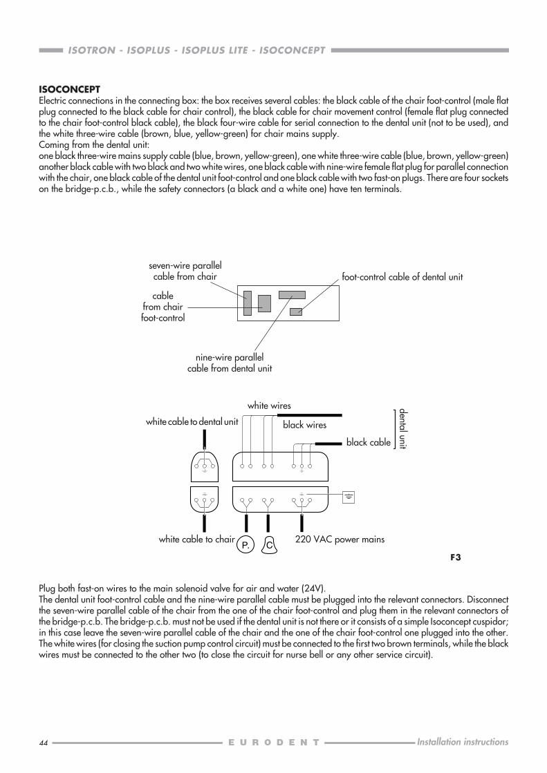
Plug both fast-on wires to the main solenoid valve for air and water (24V).The dental unit foot-control cable and the nine-wire parallel cable must be plugged into the relevant connectors. Disconnectthe seven-wire parallel cable of the chair from the one of the chair foot-control and plug them in the relevant connectors ofthe bridge-p.c.b. The bridge-p.c.b. must not be used if the dental unit is not there or it consists of a simple Isoconcept cuspidor;in this case leave the seven-wire parallel cable of the chair and the one of the chair foot-control one plugged into the other.The white wires (for closing the suction pump control circuit) must be connected to the first two brown terminals, while the blackwires must be connected to the other two (to close the circuit for nurse bell or any other service circuit).
ISOCONCEPTElectric connections in the connecting box: the box receives several cables: the black cable of the chair foot-control (male flatplug connected to the black cable for chair control), the black cable for chair movement control (female flat plug connectedto the chair foot-control black cable), the black four-wire cable for serial connection to the dental unit (not to be used), andthe white three-wire cable (brown, blue, yellow-green) for chair mains supply.Coming from the dental unit:one black three-wire mains supply cable (blue, brown, yellow-green), one white three-wire cable (blue, brown, yellow-green)another black cable with two black and two white wires, one black cable with nine-wire female flat plug for parallel connectionwith the chair, one black cable of the dental unit foot-control and one black cable with two fast-on plugs. There are four socketson the bridge-p.c.b., while the safety connectors (a black and a white one) have ten terminals.
white cable to chair
foot-control cable of dental unit
white cable to dental unit
seven-wire parallelcable from chair
cablefrom chairfoot-control
nine-wire parallelcable from dental unit
F3P. C
white wires
black cable
220 VAC power mains
dental unit
black wires
45
ISOTRON - ISOPLUS - ISOPLUS LITE - ISOCONCEPT
Installation instructions
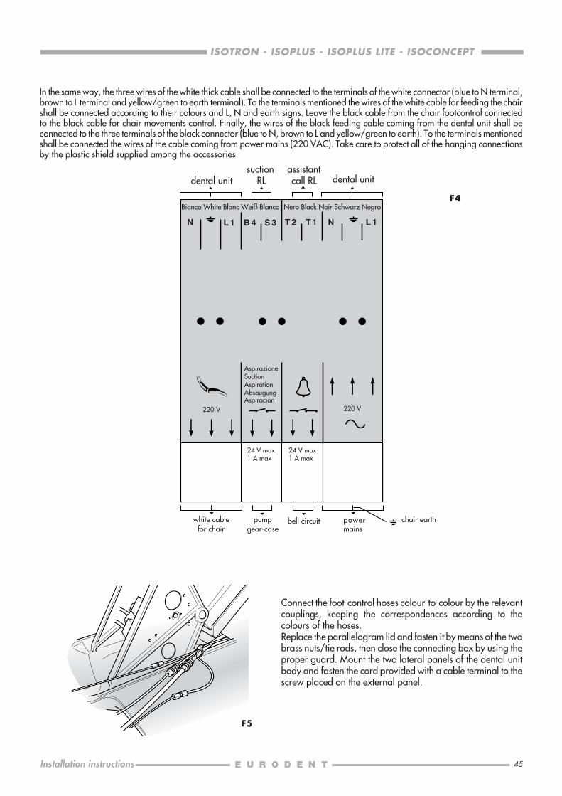
In the same way, the three wires of the white thick cable shall be connected to the terminals of the white connector (blue to N terminal,brown to L terminal and yellow/green to earth terminal). To the terminals mentioned the wires of the white cable for feeding the chairshall be connected according to their colours and L, N and earth signs. Leave the black cable from the chair footcontrol connectedto the black cable for chair movements control. Finally, the wires of the black feeding cable coming from the dental unit shall beconnected to the three terminals of the black connector (blue to N, brown to L and yellow/green to earth). To the terminals mentionedshall be connected the wires of the cable coming from power mains (220 VAC). Take care to protect all of the hanging connectionsby the plastic shield supplied among the accessories.
220 V 220 V
N L 1 B 4 S 3 T 2 T 1 N L 1
F4Bianco White Blanc Weiß Blanco Nero Black Noir Schwarz Negro
AspirazioneSuctionAspirationAbsaugungAspiración
24 V max1 A max
24 V max1 A max
Connect the foot-control hoses colour-to-colour by the relevantcouplings, keeping the correspondences according to thecolours of the hoses.Replace the parallelogram lid and fasten it by means of the twobrass nuts/tie rods, then close the connecting box by using theproper guard. Mount the two lateral panels of the dental unitbody and fasten the cord provided with a cable terminal to thescrew placed on the external panel.
F5
suction RL
assistantcall RLdental unit dental unit
chair earthbell circuitwhite cablefor chair
pumpgear-case
powermains
46
ISOTRON - ISOPLUS - ISOPLUS LITE - ISOCONCEPT
Installation instructions
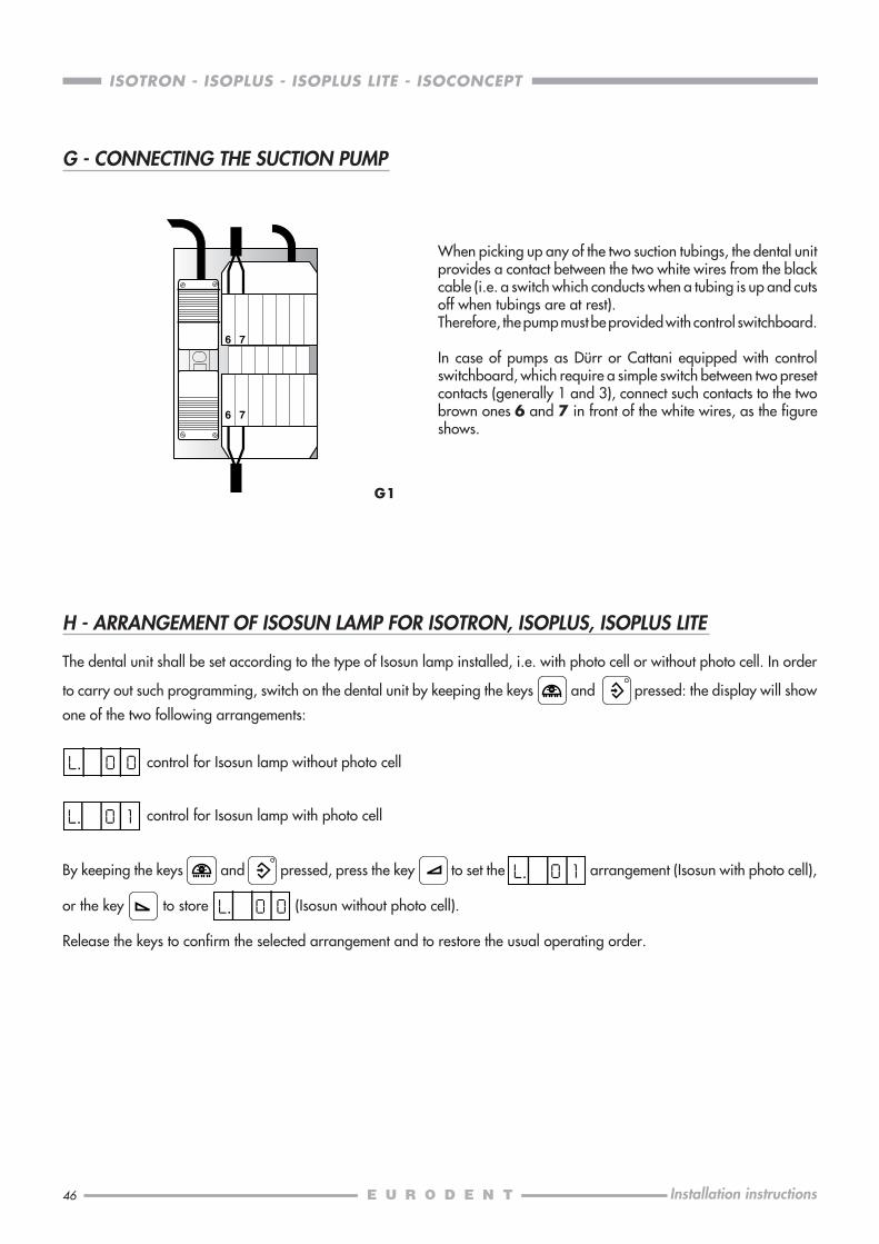
When picking up any of the two suction tubings, the dental unitprovides a contact between the two white wires from the blackcable (i.e. a switch which conducts when a tubing is up and cutsoff when tubings are at rest).Therefore, the pump must be provided with control switchboard.
In case of pumps as Dürr or Cattani equipped with controlswitchboard, which require a simple switch between two presetcontacts (generally 1 and 3), connect such contacts to the twobrown ones 6 and 7 in front of the white wires, as the figureshows.
6 7
6 7
G - CONNECTING THE SUCTION PUMP
H - ARRANGEMENT OF ISOSUN LAMP FOR ISOTRON, ISOPLUS, ISOPLUS LITE
The dental unit shall be set according to the type of Isosun lamp installed, i.e. with photo cell or without photo cell. In order
to carry out such programming, switch on the dental unit by keeping the keys and pressed: the display will show
one of the two following arrangements:
control for Isosun lamp without photo cell
control for Isosun lamp with photo cell
By keeping the keys and pressed, press the key to set the arrangement (Isosun with photo cell),
or the key to store (Isosun without photo cell).
Release the keys to confirm the selected arrangement and to restore the usual operating order.
G1
47
ISOTRON - ISOPLUS - ISOPLUS LITE - ISOCONCEPT
Installation instructions
I2
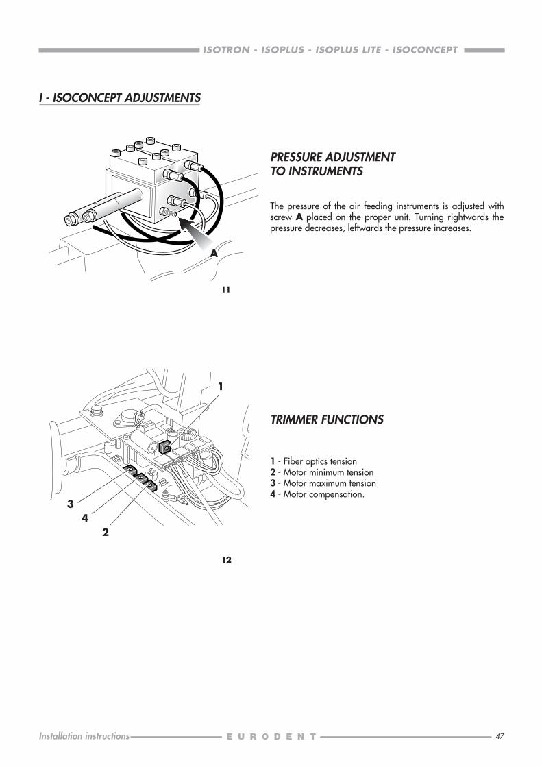
TRIMMER FUNCTIONS
1 - Fiber optics tension2 - Motor minimum tension3 - Motor maximum tension4 - Motor compensation.
1
34
I1
I - ISOCONCEPT ADJUSTMENTS
A
2
PRESSURE ADJUSTMENTTO INSTRUMENTS
The pressure of the air feeding instruments is adjusted withscrew A placed on the proper unit. Turning rightwards thepressure decreases, leftwards the pressure increases.

49
ISOTRON - ISOPLUS - ISOPLUS LITE - ISOCONCEPT
Notice d'installation
CONDITIONS PRELIMINAIRES .................................................................................. 50DECLARATION DE RESPONSABILITE ........................................................................ 50PREDISPOSITION..................................................................................................... 51
A EMBALLAGE DES FAUTEUILS ISORAMA ET ISO .....................................................52TRANSPORT ET INSTALLATION ........................................................................... 53
B INSTALLATION DU FAUTEUIL ISORAMA ...............................................................54PREPARATION ................................................................................................... 54DEBLOCAGE DU DOSSIER .................................................................................. 54FIXATION DU DOSSIER ...................................................................................... 54ESSAI DE FONCTIONNEMENT ........................................................................... 55COUSSIN DOSSIER ............................................................................................ 55COUSSIN SIEGE................................................................................................. 56
C INSTALLATION DU FAUTEUIL ISO ........................................................................57DOSSIER ............................................................................................................ 57TAPISSERIE DOSSIER .......................................................................................... 57TAPISSERIE SIEGE ............................................................................................... 58MONTAGE DES ACCOUDOIRS .......................................................................... 58
D APPUI-TETE POUR FAUTEUILS ISORAMA ET ISO ................................................... 60
E INSTALLATION DES UNITSISOTRON, ISOPLUS, ISOPLUS LITE, ISOCONCEPT .................................................61
F CONNEXIONS ELECTRIQUES ET ELECTROPNEUMATIQUES .................................... 66ISOTRON, ISOPLUS, ISOPLUS LITE ....................................................................... 66ISOCONCEPT .................................................................................................... 68
G CONNEXIONS DE LA POMPE D’ASPIRATION....................................................... 70
H PREDISPOSITION DE LA LAMPE ISOSUN POUR ISOTRON, ISOPLUS, ISOPLUS LITE ... 70
I REGLAGES ISOCONCEPT .................................................................................... 71RÉGLAGE PRESSION AUX INSTRUMENTS ........................................................... 71FONCTIONS DES CONDENSATEURS.................................................................. 71
TABLE DES MATIERES Page
50
ISOTRON - ISOPLUS - ISOPLUS LITE - ISOCONCEPT
Notice d'installation
CONDITIONS PRELIMINAIRES
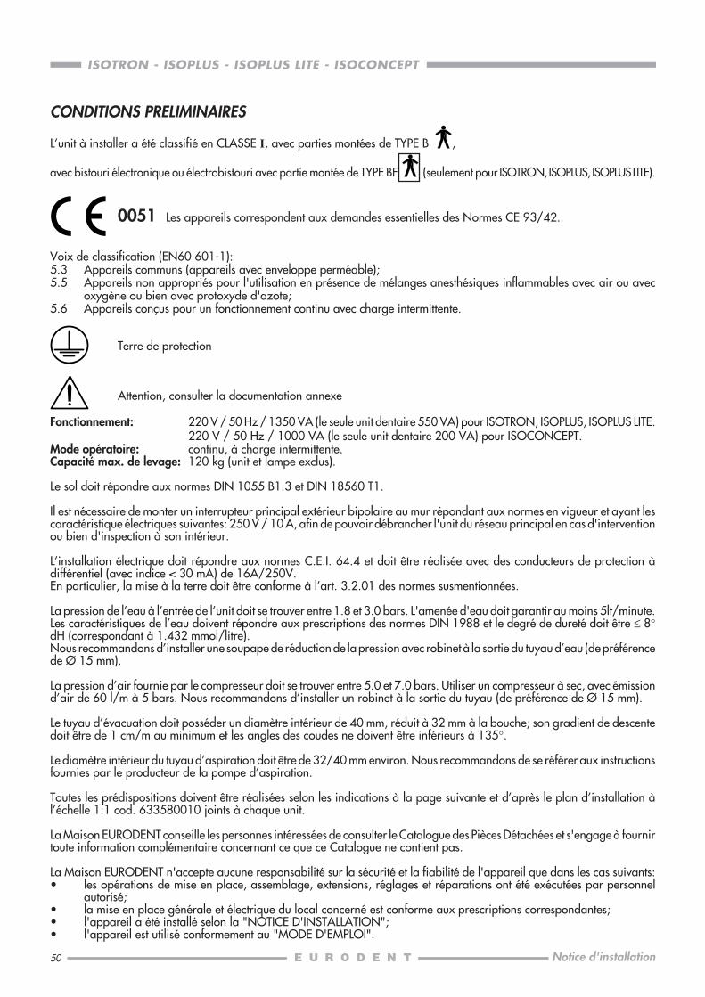
L’unit à installer a été classifié en CLASSE I, avec parties montées de TYPE B ,
avec bistouri électronique ou électrobistouri avec partie montée de TYPE BF (seulement pour ISOTRON, ISOPLUS, ISOPLUS LITE).
0051 Les appareils correspondent aux demandes essentielles des Normes CE 93/42.
Voix de classification (EN60 601-1):5.3 Appareils communs (appareils avec enveloppe perméable);5.5 Appareils non appropriés pour l'utilisation en présence de mélanges anesthésiques inflammables avec air ou avec
oxygène ou bien avec protoxyde d'azote;5.6 Appareils conçus pour un fonctionnement continu avec charge intermittente.
Terre de protection
Attention, consulter la documentation annexe
Fonctionnement: 220 V / 50 Hz / 1350 VA (le seule unit dentaire 550 VA) pour ISOTRON, ISOPLUS, ISOPLUS LITE.220 V / 50 Hz / 1000 VA (le seule unit dentaire 200 VA) pour ISOCONCEPT.
Mode opératoire: continu, à charge intermittente.Capacité max. de levage: 120 kg (unit et lampe exclus).
Le sol doit répondre aux normes DIN 1055 B1.3 et DIN 18560 T1.
Il est nécessaire de monter un interrupteur principal extérieur bipolaire au mur répondant aux normes en vigueur et ayant lescaractéristique électriques suivantes: 250 V / 10 A, afin de pouvoir débrancher l'unit du réseau principal en cas d'interventionou bien d'inspection à son intérieur.
L’installation électrique doit répondre aux normes C.E.I. 64.4 et doit être réalisée avec des conducteurs de protection àdifférentiel (avec indice < 30 mA) de 16A/250V.En particulier, la mise à la terre doit être conforme à l’art. 3.2.01 des normes susmentionnées.
La pression de l’eau à l’entrée de l’unit doit se trouver entre 1.8 et 3.0 bars. L'amenée d'eau doit garantir au moins 5lt/minute.Les caractéristiques de l’eau doivent répondre aux prescriptions des normes DIN 1988 et le degré de dureté doit être ≤ 8°dH (correspondant à 1.432 mmol/litre).Nous recommandons d’installer une soupape de réduction de la pression avec robinet à la sortie du tuyau d’eau (de préférencede Ø 15 mm).
La pression d’air fournie par le compresseur doit se trouver entre 5.0 et 7.0 bars. Utiliser un compresseur à sec, avec émissiond’air de 60 l/m à 5 bars. Nous recommandons d’installer un robinet à la sortie du tuyau (de préférence de Ø 15 mm).
Le tuyau d’évacuation doit posséder un diamètre intérieur de 40 mm, réduit à 32 mm à la bouche; son gradient de descentedoit être de 1 cm/m au minimum et les angles des coudes ne doivent être inférieurs à 135°.
Le diamètre intérieur du tuyau d’aspiration doit être de 32/40 mm environ. Nous recommandons de se référer aux instructionsfournies par le producteur de la pompe d’aspiration.
Toutes les prédispositions doivent être réalisées selon les indications à la page suivante et d’après le plan d’installation àl’échelle 1:1 cod. 633580010 joints à chaque unit.
La Maison EURODENT conseille les personnes intéressées de consulter le Catalogue des Pièces Détachées et s'engage à fournirtoute information complémentaire concernant ce que ce Catalogue ne contient pas.
La Maison EURODENT n'accepte aucune responsabilité sur la sécurité et la fiabilité de l'appareil que dans les cas suivants:• les opérations de mise en place, assemblage, extensions, réglages et réparations ont été exécutées par personnel
autorisé;• la mise en place générale et électrique du local concerné est conforme aux prescriptions correspondantes;• l'appareil a été installé selon la "NOTICE D'INSTALLATION";• l'appareil est utilisé conformement au "MODE D'EMPLOI".

51
ISOTRON - ISOPLUS - ISOPLUS LITE - ISOCONCEPT
Notice d'installation
PREDISPOSITION
..
.....
5060
175
E
A
A 3/8"G
20
B
C D
35
295
150
80
40
40 30
40
B
C
3/8"G
20
25
ø 32ø
40
D
E
25
500
ø 32
ø 4
0
ISOSUN
A. Eau: 3/8" G
B. Air: 3/8" G
C. Evacuation: Ø 32
D. Aspiration: Ø 32
Activation pompe: 2 x 1 mm2
E. Sonnette: 2 x 0,5 mm2
Réseau: 3 x 2,5 mm2
Trou de fixationau sol
Trou de fixationau sol
52
ISOTRON - ISOPLUS - ISOPLUS LITE - ISOCONCEPT
Notice d'installation
A0
1
ALTO
BOLOGNA
ITALYCOD OPZIONEMATR.
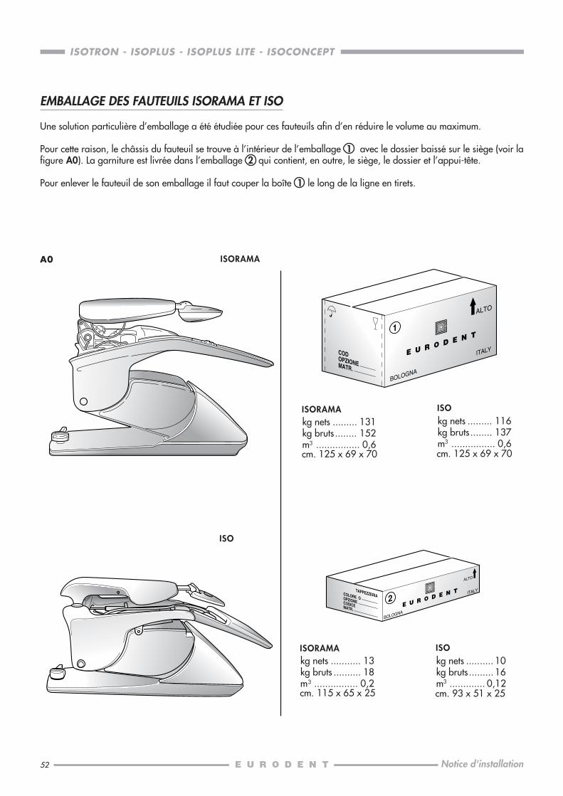
kg nets ......... 131kg bruts ........ 152m3 ................ 0,6cm. 125 x 69 x 70
2
ALTO
BOLOGNA
ITALYCOLORE OOPZIONE
TAPPEZZERIA
CODICEMATR.
ISORAMAkg nets ......... 116kg bruts ........ 137m3 ................ 0,6cm. 125 x 69 x 70
ISO
kg nets ........... 13kg bruts .......... 18m3 ................ 0,2cm. 115 x 65 x 25
ISORAMAkg nets .......... 10kg bruts ......... 16m3 ............. 0,12cm. 93 x 51 x 25
ISO
ISORAMA
ISO
EMBALLAGE DES FAUTEUILS ISORAMA ET ISO
Une solution particulière d’emballage a été étudiée pour ces fauteuils afin d’en réduire le volume au maximum.
Pour cette raison, le châssis du fauteuil se trouve à l’intérieur de l’emballage 1 avec le dossier baissé sur le siège (voir lafigure A0). La garniture est livrée dans l’emballage 2 qui contient, en outre, le siège, le dossier et l’appui-tête.
Pour enlever le fauteuil de son emballage il faut couper la boîte 1 le long de la ligne en tirets.
53
ISOTRON - ISOPLUS - ISOPLUS LITE - ISOCONCEPT
Notice d'installation
A1
A2
B
AA
B
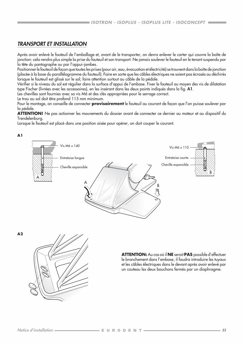
TRANSPORT ET INSTALLATION
Après avoir enlevé le fauteuil de l’emballage et, avant de le transporter, on devra enlever le carter qui couvre la boîte dejonction: cela rendra plus simple la prise du fauteuil et son transport. Ne jamais soulever le fauteuil en le tenant suspendu parla tête du pantographe ou par l’appui-jambes.Positionner le fauteuil de façon que toutes les prises (pour air, eau, évacuation et électricité) se trouvent dans la boîte de jonction(placée à la base du parallélogramme du fauteuil). Faire en sorte que les câbles électriques ne soient pas écrasés ou déchiréslorsque le fauteuil est glissé sur le sol; faire attention surtout au câble de la pédale.Vérifier si le niveau du sol est régulier dans la surface d’appui de l’embase. Fixer le fauteuil au moyen des vis de dilatationtype Fischer (livrées avec les accessoires), en les insérant dans les deux points indiqués dans la fig. A1.Les chevilles sont fournies avec sa vis M6 et des clés appropriées pour le serrage correct.Le trou au sol doit être profond 115 mm minimum.Pour le montage, on conseille de connecter provisoirement le fauteuil au courant de façon que l’on puisse soulever parla pédale.ATTENTION! Ne pas actionner les mouvements du dossier avant de connecter ce dernier au moteur et au dispositif duTrendelenburg.Lorsque le fauteuil est placé dans une position aisée pour opérer, on doit couper le courant.
ATTENTION: Au cas où il NE serait PAS possible d’effectuerle branchement dans l’embase, il faudra introduire les tuyauxet les câbles électriques dans le devant après avoir enlevé parun couteau les deux bouchons fermés par un diaphragme.
Vis M6 x 140
Cheville expansible
Entretoise longue
Vis M6 x 110
Entretoise courte
Cheville expansible
54
ISOTRON - ISOPLUS - ISOPLUS LITE - ISOCONCEPT
Notice d'installation
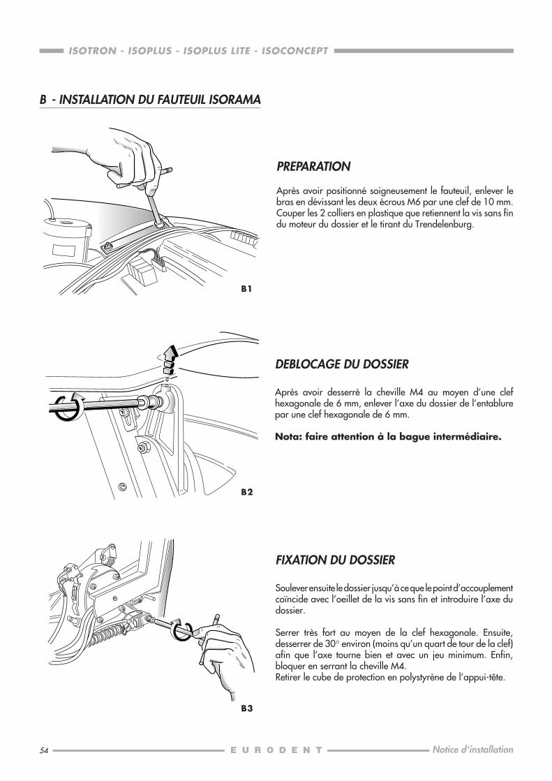
PREPARATION
Après avoir positionné soigneusement le fauteuil, enlever lebras en dévissant les deux écrous M6 par une clef de 10 mm.Couper les 2 colliers en plastique que retiennent la vis sans findu moteur du dossier et le tirant du Trendelenburg.
DEBLOCAGE DU DOSSIER
Après avoir desserré la cheville M4 au moyen d’une clefhexagonale de 6 mm, enlever l’axe du dossier de l’entablurepar une clef hexagonale de 6 mm.
Nota: faire attention à la bague intermédiaire.
FIXATION DU DOSSIER
Soulever ensuite le dossier jusqu’à ce que le point d’accouplementcoïncide avec l’oeillet de la vis sans fin et introduire l’axe dudossier.
Serrer très fort au moyen de la clef hexagonale. Ensuite,desserrer de 30° environ (moins qu’un quart de tour de la clef)afin que l’axe tourne bien et avec un jeu minimum. Enfin,bloquer en serrant la cheville M4.Retirer le cube de protection en polystyrène de l’appui-tête.
B1
B2
B3
B - INSTALLATION DU FAUTEUIL ISORAMA
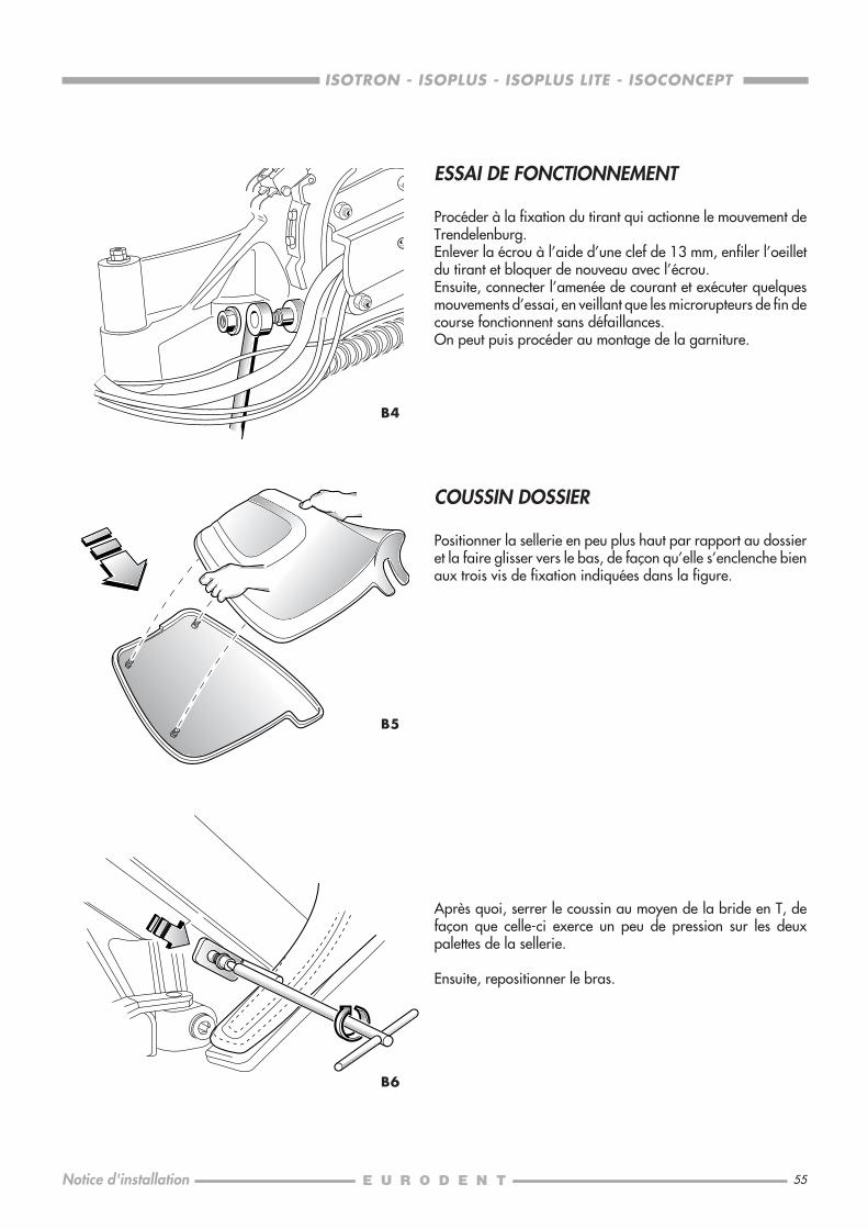
55
ISOTRON - ISOPLUS - ISOPLUS LITE - ISOCONCEPT
Notice d'installation
B4
B6
B5
ESSAI DE FONCTIONNEMENT
Procéder à la fixation du tirant qui actionne le mouvement deTrendelenburg.Enlever la écrou à l’aide d’une clef de 13 mm, enfiler l’oeilletdu tirant et bloquer de nouveau avec l’écrou.Ensuite, connecter l’amenée de courant et exécuter quelquesmouvements d’essai, en veillant que les microrupteurs de fin decourse fonctionnent sans défaillances.On peut puis procéder au montage de la garniture.
COUSSIN DOSSIER
Positionner la sellerie en peu plus haut par rapport au dossieret la faire glisser vers le bas, de façon qu’elle s’enclenche bienaux trois vis de fixation indiquées dans la figure.
Après quoi, serrer le coussin au moyen de la bride en T, defaçon que celle-ci exerce un peu de pression sur les deuxpalettes de la sellerie.
Ensuite, repositionner le bras.
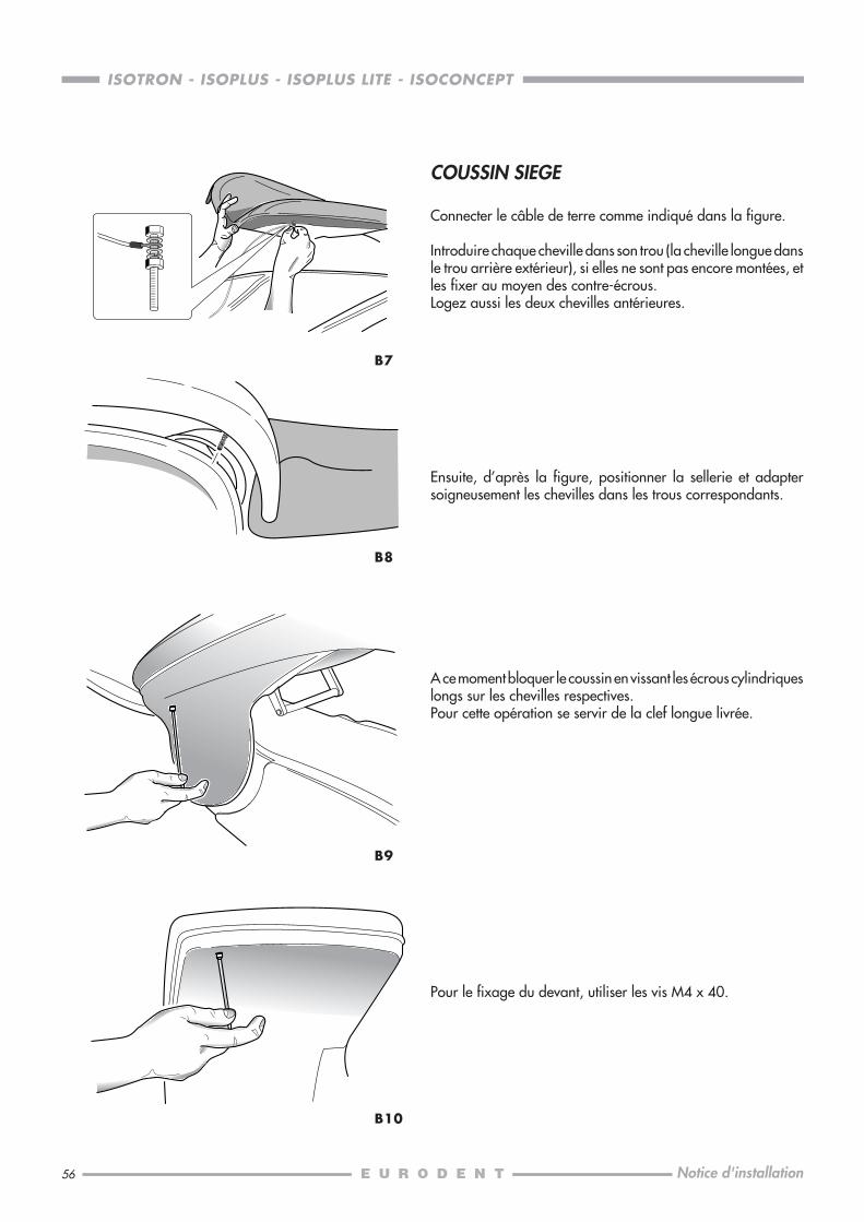
56
ISOTRON - ISOPLUS - ISOPLUS LITE - ISOCONCEPT
Notice d'installation
B8
B10
B7
B9
COUSSIN SIEGE
Connecter le câble de terre comme indiqué dans la figure.
Introduire chaque cheville dans son trou (la cheville longue dansle trou arrière extérieur), si elles ne sont pas encore montées, etles fixer au moyen des contre-écrous.Logez aussi les deux chevilles antérieures.
Ensuite, d’après la figure, positionner la sellerie et adaptersoigneusement les chevilles dans les trous correspondants.
A ce moment bloquer le coussin en vissant les écrous cylindriqueslongs sur les chevilles respectives.Pour cette opération se servir de la clef longue livrée.
Pour le fixage du devant, utiliser les vis M4 x 40.
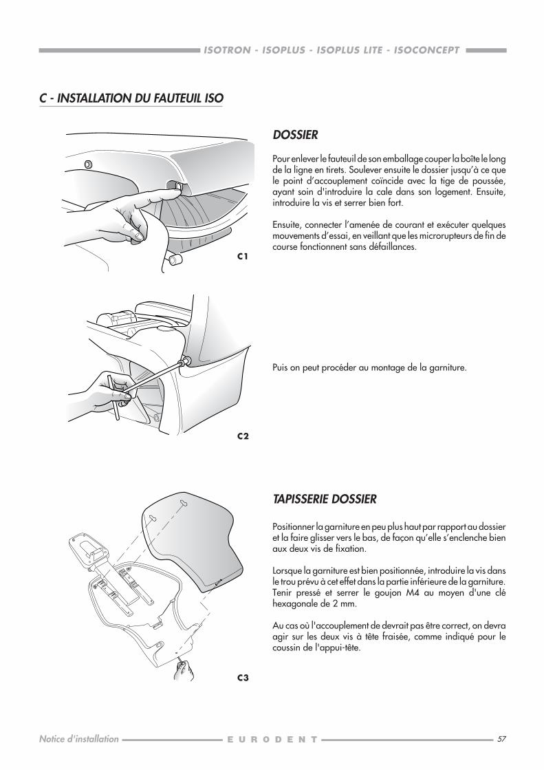
57
ISOTRON - ISOPLUS - ISOPLUS LITE - ISOCONCEPT
Notice d'installation
C - INSTALLATION DU FAUTEUIL ISO
DOSSIER
Pour enlever le fauteuil de son emballage couper la boîte le longde la ligne en tirets. Soulever ensuite le dossier jusqu’à ce quele point d’accouplement coïncide avec la tige de poussée,ayant soin d'introduire la cale dans son logement. Ensuite,introduire la vis et serrer bien fort.
Ensuite, connecter l’amenée de courant et exécuter quelquesmouvements d’essai, en veillant que les microrupteurs de fin decourse fonctionnent sans défaillances.
Puis on peut procéder au montage de la garniture.
C2
TAPISSERIE DOSSIER
Positionner la garniture en peu plus haut par rapport au dossieret la faire glisser vers le bas, de façon qu’elle s’enclenche bienaux deux vis de fixation.
Lorsque la garniture est bien positionnée, introduire la vis dansle trou prévu à cet effet dans la partie inférieure de la garniture.Tenir pressé et serrer le goujon M4 au moyen d'une cléhexagonale de 2 mm.
Au cas où l'accouplement de devrait pas être correct, on devraagir sur les deux vis à tête fraisée, comme indiqué pour lecoussin de l'appui-tête.
C3
C1
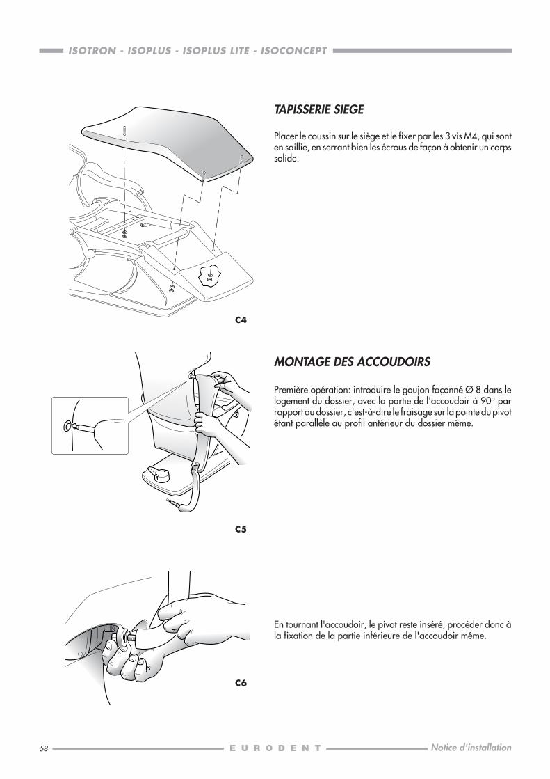
58
ISOTRON - ISOPLUS - ISOPLUS LITE - ISOCONCEPT
Notice d'installation
TAPISSERIE SIEGE
Placer le coussin sur le siège et le fixer par les 3 vis M4, qui sonten saillie, en serrant bien les écrous de façon à obtenir un corpssolide.
C4
C5
En tournant l'accoudoir, le pivot reste inséré, procéder donc àla fixation de la partie inférieure de l'accoudoir même.
C6
MONTAGE DES ACCOUDOIRS
Première opération: introduire le goujon façonné Ø 8 dans lelogement du dossier, avec la partie de l'accoudoir à 90° parrapport au dossier, c'est-à-dire le fraisage sur la pointe du pivotétant parallèle au profil antérieur du dossier même.
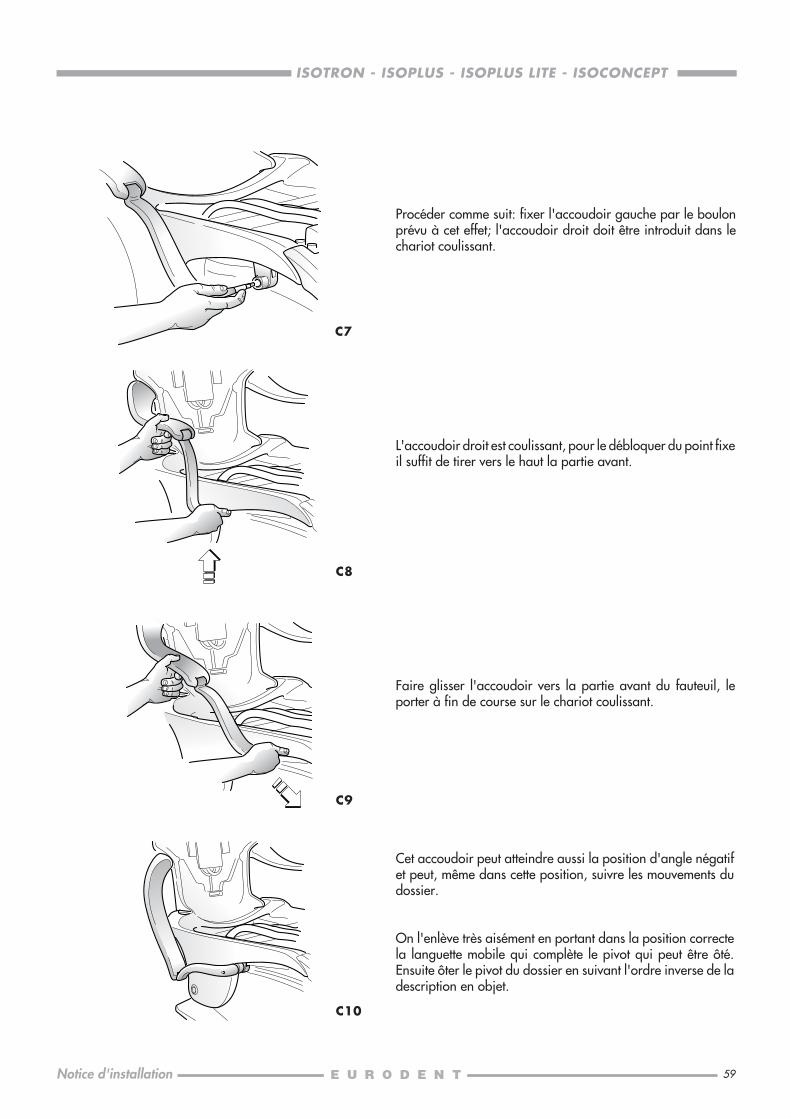
59
ISOTRON - ISOPLUS - ISOPLUS LITE - ISOCONCEPT
Notice d'installation
Procéder comme suit: fixer l'accoudoir gauche par le boulonprévu à cet effet; l'accoudoir droit doit être introduit dans lechariot coulissant.
C7
L'accoudoir droit est coulissant, pour le débloquer du point fixeil suffit de tirer vers le haut la partie avant.
C8
C9
C10
Cet accoudoir peut atteindre aussi la position d'angle négatifet peut, même dans cette position, suivre les mouvements dudossier.
On l'enlève très aisément en portant dans la position correctela languette mobile qui complète le pivot qui peut être ôté.Ensuite ôter le pivot du dossier en suivant l'ordre inverse de ladescription en objet.
Faire glisser l'accoudoir vers la partie avant du fauteuil, leporter à fin de course sur le chariot coulissant.
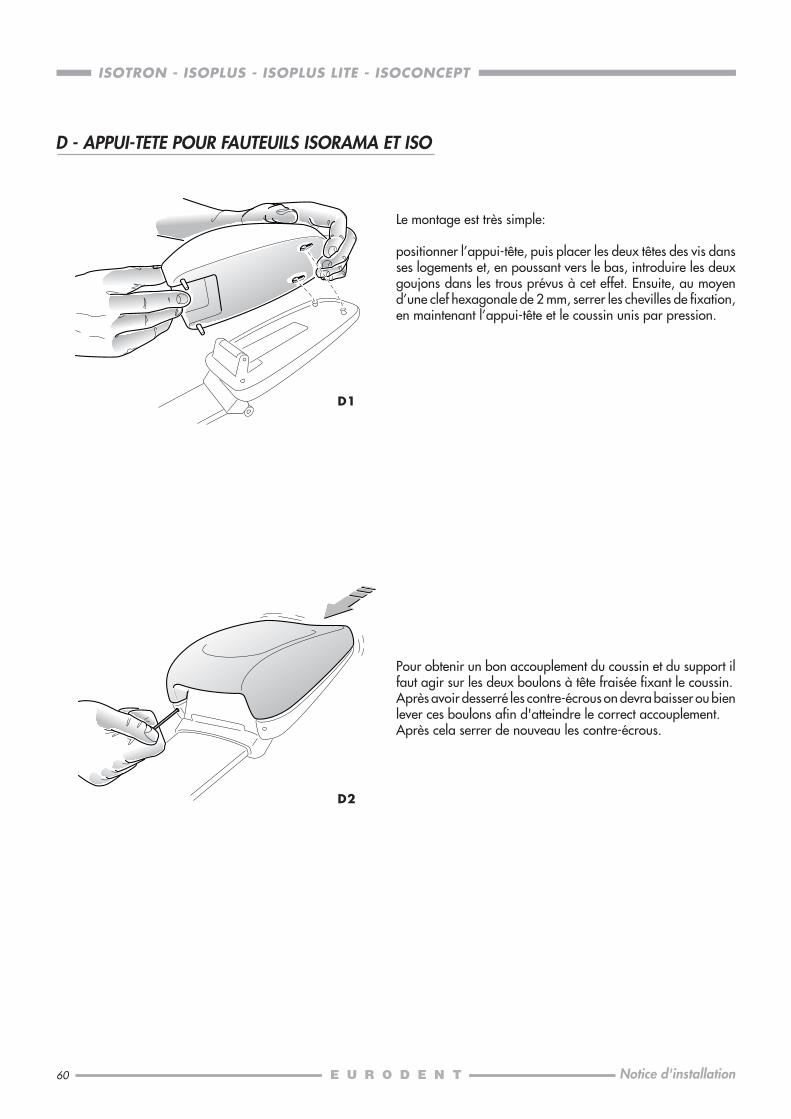
60
ISOTRON - ISOPLUS - ISOPLUS LITE - ISOCONCEPT
Notice d'installation
D2
D - APPUI-TETE POUR FAUTEUILS ISORAMA ET ISO
D1
Le montage est très simple:
positionner l’appui-tête, puis placer les deux têtes des vis dansses logements et, en poussant vers le bas, introduire les deuxgoujons dans les trous prévus à cet effet. Ensuite, au moyend’une clef hexagonale de 2 mm, serrer les chevilles de fixation,en maintenant l’appui-tête et le coussin unis par pression.
Pour obtenir un bon accouplement du coussin et du support ilfaut agir sur les deux boulons à tête fraisée fixant le coussin.Après avoir desserré les contre-écrous on devra baisser ou bienlever ces boulons afin d'atteindre le correct accouplement.Après cela serrer de nouveau les contre-écrous.

61
ISOTRON - ISOPLUS - ISOPLUS LITE - ISOCONCEPT
Notice d'installation
E0
E1
E2
Nous recommandons d’enlever non seulement le carter de laboîte de jonction, mais aussi le couvercle du parallélogrammedu fauteuil, de façon que l’on puisse opérer plus facilement lorsde l’introduction des tuyaux et des câbles de l’unit. Enlever cecouvercle en dévissant les deux écrous longs de laiton qui setrouvent sous le couvercle même et qui fixent ce dernier aux tigessupérieures du parallélogramme.Le fauteuil sera fixé au sol insérant les vis de dilatation dans lestrous prévus sur le devant de la plate-forme de base.
Monter le châssis de l’unit sur le support du fauteuil au moyendes goujons et des vis à tête hexagonale en dotation (contenusdans la boîte “ACCESSOIRES” à l’intérieur de l’emballage“EMBASE”).
ISOTRON, ISOPLUS, ISOPLUS LITEAvant de serrer les vis et les écrous il faut mettre à niveau lechâssis en horizontal et en vertical. Les goujons doivent êtreintroduits dans les trous se trouvant en bas au support, les vis aucontraire dans ceux situés plus en haut.
ISOCONCEPTPour faciliter cette opération, utiliser l'ultérieur goujon b.t.v.fourni qui devra être inséré avec l'autre en dotation dans lesdeux trous se trouvant sur la partie inférieure.Avant de serrer les deux vis et l'écrou intermédiaire il faut mettreà niveau le châssis en horizontal et en vertical; enlever le goujonà tête b.t.v. du trou en bas et le remplacer par la troisième visen dotation.
m3 ........... 0,555cm. 96 x 89 x 65
kg nets .......... 22kg bruts ......... 33
m3 ...........0,428cm. 88 x 76 x 64
L’unit est livré dans deux boîtes: celle marquée par l’étiquette“EMBASE” contient le châssis et le bras pour l’assistante, cellemarquée par “TABLETTE” contient le bras pour l’opérateur avecbras de rappel, les modules et le plateau à instruments.Aux prises d’air et d’eau il faudra prévoir des robinets.Il est indispensable de purger soigneusement les conduites d’airet d’eau avant de les raccorder à l’unit.
E - INSTALLATION DES UNITS ISOTRON, ISOPLUS, ISOPLUS LITE, ISOCONCEPT
kg nets .......... 71kg bruts ......... 88
m3 ........... 0,555cm. 96 x 89 x 65
ISOTRONISOPLUS
ISOPLUS LITEISOCONCEPT
m3 ...........0,428cm. 88 x 76 x 64
"EMBASE"
"TABLETTE"
kg nets .......... 46kg bruts ......... 65
kg nets .......... 18kg bruts ......... 30
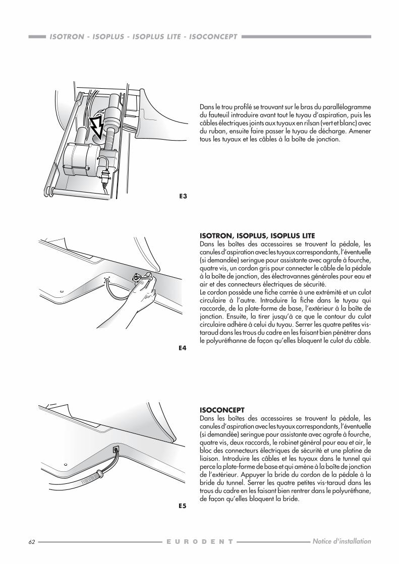
62
ISOTRON - ISOPLUS - ISOPLUS LITE - ISOCONCEPT
Notice d'installation
E3
ISOTRON, ISOPLUS, ISOPLUS LITEDans les boîtes des accessoires se trouvent la pédale, lescanules d’aspiration avec les tuyaux correspondants, l’éventuelle(si demandée) seringue pour assistante avec agrafe à fourche,quatre vis, un cordon gris pour connecter le câble de la pédaleà la boîte de jonction, des électrovannes générales pour eau etair et des connecteurs électriques de sécurité.Le cordon possède une fiche carrée à une extrémité et un culotcirculaire à l’autre. Introduire la fiche dans le tuyau quiraccorde, de la plate-forme de base, l’extérieur à la boîte dejonction. Ensuite, la tirer jusqu’à ce que le contour du culotcirculaire adhère à celui du tuyau. Serrer les quatre petites vis-taraud dans les trous du cadre en les faisant bien pénétrer dansle polyuréthanne de façon qu’elles bloquent le culot du câble.
E4
ISOCONCEPTDans les boîtes des accessoires se trouvent la pédale, lescanules d’aspiration avec les tuyaux correspondants, l’éventuelle(si demandée) seringue pour assistante avec agrafe à fourche,quatre vis, deux raccords, le robinet général pour eau et air, lebloc des connecteurs électriques de sécurité et une platine deliaison. Introduire les câbles et les tuyaux dans le tunnel quiperce la plate-forme de base et qui amène à la boîte de jonctionde l’extérieur. Appuyer la bride du cordon de la pédale à labride du tunnel. Serrer les quatre petites vis-taraud dans lestrous du cadre en les faisant bien rentrer dans le polyuréthane,de façon qu’elles bloquent la bride.
E5
Dans le trou profilé se trouvant sur le bras du parallélogrammedu fauteuil introduire avant tout le tuyau d’aspiration, puis lescâbles électriques joints aux tuyaux en rilsan (vert et blanc) avecdu ruban, ensuite faire passer le tuyau de décharge. Amenertous les tuyaux et les câbles à la boîte de jonction.

63
ISOTRON - ISOPLUS - ISOPLUS LITE - ISOCONCEPT
Notice d'installation
A ce moment on peut installer le bras de la tablette de l’unit(ayant soin d’introduire d’abord le cordon et les tuyaux dansle châssis) et bloquer la course du bras en insérant la vis etl’écrou (en dotation avec les accessoires) dans le trou dugoujon.
ISOTRON, ISOPLUS, ISOPLUS LITEEnclencher le cordon du bras à la prise CN1 (en haut, àgauche) sur la platine de basse tension.Ensuite, connecter le tuyau blanc au raccord rapide pour l’airaux modules situé à droite des réducteurs d’air. Connecter letuyau rouge (seulement ISOTRON) au raccord situé sur lecouvercle du collecteur d’amalgame et le tuyau vert au groupede distribution de l’eau (pour verre, seringue assistante etmodules) se trouvant au côté fauteuil.
ISOCONCEPTSur la platine, enclencher le cordon du bras à la prise X1 et X2(en haut, à gauche). Connecter le tuyau blanc 3/5 au raccordpour l'air permanent, situé à droite du réducteur d'air; connecterle tuyau vert au côté de la vanne du jet de verre. Les tuyauxrestants doivent être reliés aux raccords correspondants rapidesplacés au groupe hydrique.
NOTA: Lors du montage respecter toujours les correspondancesdes couleurs des tuyaux.
E6
E7
E8
Fixer le plateau à instruments sous la tablette porte-modules(pour faciliter l’opération, utiliser une clef tubulaire ou en tubede 17).
Introduire le câble et l’axe du bras assistante dans son proprelogement (sur le fond du châssis, côté fauteuil) et bloquer l’axepar la bague élastique Seeger et la rondelle entretoise derenfort.Faire passer le câble à travers le châssis jusqu’à ce qu’ils’enclenche à la prise C5 (pour ISOTRON) ou C2 (pourISOPLUS et ISOPLUS LITE) se trouvant sur la platine de bassetension ou bien sur la prise X5 de la platine châssis pourISOCONCEPT.N.B. Faire attention à ce que le câble ne soit pas pendant sousle châssis.Introduire le groupe de friction dans le trou à côté du logementde l’axe et serrer bien la vis.
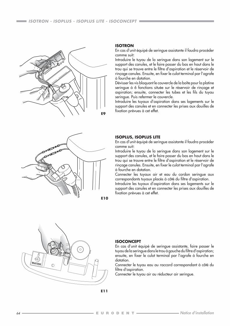
64
ISOTRON - ISOPLUS - ISOPLUS LITE - ISOCONCEPT
Notice d'installation
E9
ISOTRONEn cas d’unit équipé de seringue assistante il faudra procédercomme suit:Introduire le tuyau de la seringue dans son logement sur lesupport des canules, et le faire passer du bas en haut dans letrou qui se trouve entre le filtre d’aspiration et le réservoir derinçage canules. Ensuite, en fixer le culot terminal par l’agrafeà fourche en dotation.Dévisser les vis bloquant le couvercle de la boîte pour la platineseringue à 6 fonctions située sur le réservoir de rinçage etaspiration; ensuite, connecter les tubes et les fils du tuyauseringue. Puis refermer le couvercle.Introduire les tuyaux d’aspiration dans ses logements sur lesupport des canules et en connecter les prises aux douilles defixation prévues à cet effet.
E10
ISOPLUS, ISOPLUS LITEEn cas d’unit équipé de seringue assistante il faudra procédercomme suit:Introduire le tuyau de la seringue dans son logement sur lesupport des canules, et le faire passer du bas en haut dans letrou qui se trouve entre le filtre d’aspiration et le réservoir derinçage canules. Ensuite, en fixer le culot terminal par l’agrafeà fourche en dotation.Connecter les tuyaux air et eau du cordon seringue auxcorrespondants tuyaux placés à côté du filtre d'aspiration.Introduire les tuyaux d’aspiration dans ses logements sur lesupport des canules et en connecter les prises aux douilles defixation prévues à cet effet.
E11
ISOCONCEPTEn cas d’unit équipé de seringue assistante, faire passer letuyau de la seringue dans le trou à gauche du filtre d'aspiration;ensuite, en fixer le culot terminal par l’agrafe à fourche endotation.Connecter le tuyau eau au raccord correspondant à côté dufiltre d'aspiration.Connecter le tuyau air au réducteur air seringue.
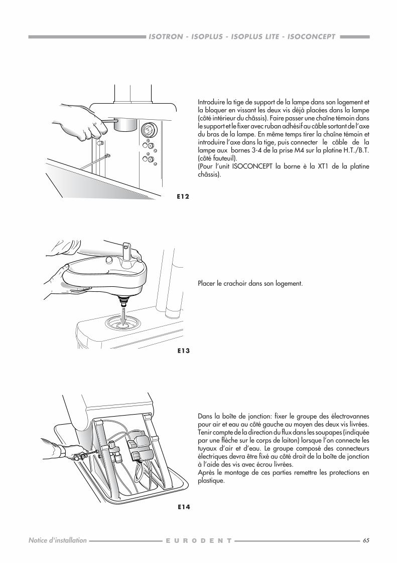
65
ISOTRON - ISOPLUS - ISOPLUS LITE - ISOCONCEPT
Notice d'installation
E12
E13
Dans la boîte de jonction: fixer le groupe des électrovannespour air et eau au côté gauche au moyen des deux vis livrées.Tenir compte de la direction du flux dans les soupapes (indiquéepar une flèche sur le corps de laiton) lorsque l’on connecte lestuyaux d’air et d’eau. Le groupe composé des connecteursélectriques devra être fixé au côté droit de la boîte de jonctionà l’aide des vis avec écrou livrées.Après le montage de ces parties remettre les protections enplastique.
Introduire la tige de support de la lampe dans son logement etla bloquer en vissant les deux vis déjà placées dans la lampe(côté intérieur du châssis). Faire passer une chaîne témoin dansle support et le fixer avec ruban adhésif au câble sortant de l’axedu bras de la lampe. En même temps tirer la chaîne témoin etintroduire l’axe dans la tige, puis connecter le câble de lalampe aux bornes 3-4 de la prise M4 sur la platine H.T./B.T.(côté fauteuil).(Pour l’unit ISOCONCEPT la borne è la XT1 de la platinechâssis).
E14
Placer le crachoir dans son logement.
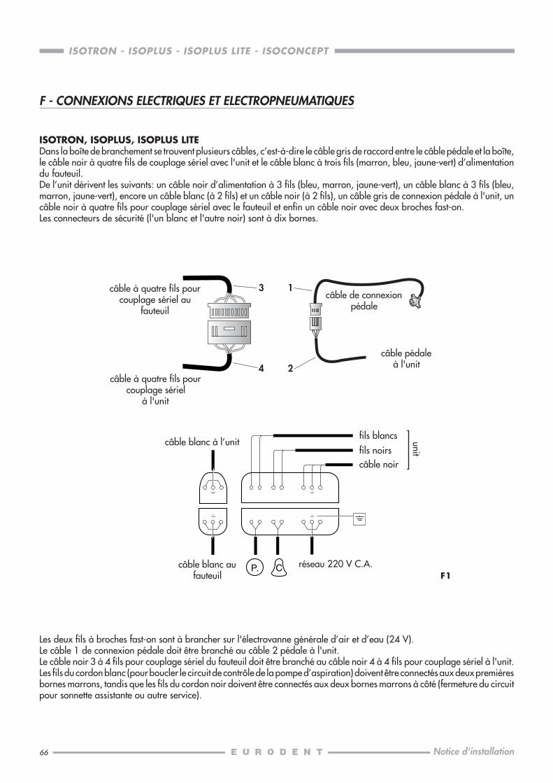
66
ISOTRON - ISOPLUS - ISOPLUS LITE - ISOCONCEPT
Notice d'installation
F - CONNEXIONS ELECTRIQUES ET ELECTROPNEUMATIQUES
ISOTRON, ISOPLUS, ISOPLUS LITEDans la boîte de branchement se trouvent plusieurs câbles, c’est-à-dire le câble gris de raccord entre le câble pédale et la boîte,le câble noir à quatre fils de couplage sériel avec l'unit et le câble blanc à trois fils (marron, bleu, jaune-vert) d’alimentationdu fauteuil.De l’unit dérivent les suivants: un câble noir d’alimentation à 3 fils (bleu, marron, jaune-vert), un câble blanc à 3 fils (bleu,marron, jaune-vert), encore un câble blanc (à 2 fils) et un câble noir (à 2 fils), un câble gris de connexion pédale à l'unit, uncâble noir à quatre fils pour couplage sériel avec le fauteuil et enfin un câble noir avec deux broches fast-on.Les connecteurs de sécurité (l'un blanc et l'autre noir) sont à dix bornes.
Les deux fils à broches fast-on sont à brancher sur l'électrovanne générale d’air et d’eau (24 V).Le câble 1 de connexion pédale doit être branché au câble 2 pédale à l'unit.Le câble noir 3 à 4 fils pour couplage sériel du fauteuil doit être branché au câble noir 4 à 4 fils pour couplage sériel à l'unit.Les fils du cordon blanc (pour boucler le circuit de contrôle de la pompe d’aspiration) doivent être connectés aux deux premièresbornes marrons, tandis que les fils du cordon noir doivent être connectés aux deux bornes marrons à côté (fermeture du circuitpour sonnette assistante ou autre service).
fils noirs
fils blancs
P. C
câble noir
câble blanc aufauteuil
réseau 220 V C.A.
unit
câble blanc à l’unit
câble à quatre fils pourcouplage sériel au
fauteuil
F1
3
4
1
2câble à quatre fils pour
couplage sérielà l'unit
câble de connexionpédale
câble pédaleà l'unit
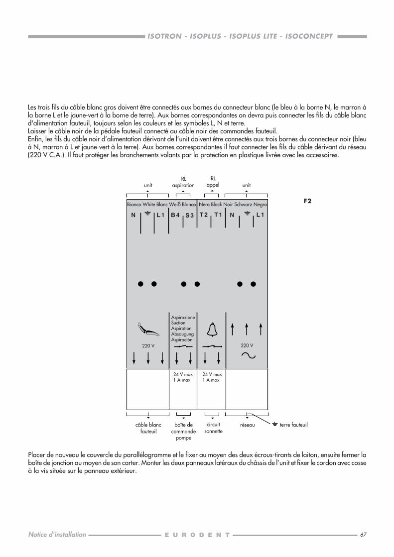
67
ISOTRON - ISOPLUS - ISOPLUS LITE - ISOCONCEPT
Notice d'installation
Les trois fils du câble blanc gros doivent être connectés aux bornes du connecteur blanc (le bleu à la borne N, le marron àla borne L et le jaune-vert à la borne de terre). Aux bornes correspondantes on devra puis connecter les fils du câble blancd'alimentation fauteuil, toujours selon les couleurs et les symboles L, N et terre.Laisser le câble noir de la pédale fauteuil connecté au câble noir des commandes fauteuil.Enfin, les fils du câble noir d’alimentation dérivant de l’unit doivent être connectés aux trois bornes du connecteur noir (bleuà N, marron à L et jaune-vert à la terre). Aux bornes correspondantes il faut connecter les fils du câble dérivant du réseau(220 V C.A.). Il faut protéger les branchements volants par la protection en plastique livrée avec les accessoires.
Placer de nouveau le couvercle du parallélogramme et le fixer au moyen des deux écrous-tirants de laiton, ensuite fermer laboîte de jonction au moyen de son carter. Monter les deux panneaux latéraux du châssis de l’unit et fixer le cordon avec cosseà la vis située sur le panneau extérieur.
220 V 220 V
N L 1 B 4 S 3 T 2 T 1 N L 1
F2Bianco White Blanc Weiß Blanco Nero Black Noir Schwarz Negro
AspirazioneSuctionAspirationAbsaugungAspiración
24 V max1 A max
24 V max1 A max
RLaspiration
RLappel unitunit
boîte decommande
pompe
câble blancfauteuil
circuitsonnette
réseau terre fauteuil

68
ISOTRON - ISOPLUS - ISOPLUS LITE - ISOCONCEPT
Notice d'installation
Les deux fils à broches fast-on sont à brancher sur l'électrovanne générale d’air et d’eau (24 V).Insérer dans les prises correspondantes le câble pédale de l’unit et le câble à 9 fils parallèle de l’unit. Déconnecter le câbleà 7 fils parallèle dérivant du fauteuil et celui de la pédale fauteuil (que vous trouverez branchés l’un sur l’autre) et les introduiredans les prises correspondantes de la platine de jonction. Au cas où la pédale de l’unit ne serait pas installé (montage ducrachoir seul), la platine de liaison ne sera pas livrée; par conséquent le câble à 7 fils parallèle dérivant du fauteuil et celuide la pédale fauteuil devront rester branchés entre eux.Les fils blancs (pour boucler le circuit de contrôle de la pompe d’aspiration) doivent être connectés aux deux premières bornesmarron, tandis que les fils noirs doivent être connectés aux deux bornes restantes (fermeture du circuit pour sonnette assistanteou autre circuit de service).
ISOCONCEPTDans la boîte de branchement se trouvent plusieurs câbles, c’est-à-dire le câble noir de la pédale fauteuil (fiche plate connectéeau câble noir de commandes fauteuil), le câble noir de commande des mouvements fauteuil (prise plate connectée au câblenoir de la pédale fauteuil), le câble noir à quatre fils de couplage sériel avec l'unit (à ne pas utiliser) et le câble blanc à troisfils (marron, bleu, jaune-vert) d’alimentation du fauteuil.De l’unit dérivent les suivants: un câble noir d’alimentation à 3 fils (bleu, marron, jaune-vert), un câble blanc à 3 fils (bleu,marron, jaune-vert), encore un câble noir à 2 fils noirs et 2 fils blancs, un autre câble noir (prise plate à 9 fils) de couplageparallèle avec le fauteuil, un câble noir de la pédale unit et enfin avec deux broches fast-on.Sur la platine de jonction se trouvent quatre prises; les connecteurs de sécurité (dont l’un est blanc et l’autre est noir) sont àdix bornes.
F3P. Ccâble blanc au
fauteuilréseau 220 V C.A.
câble pédale à l’unit
câble blanc à l’unit
câble à 7 fils parallèledérivant du fauteuil
câble dérivantde la pédale
fauteuil
câble à 9 filsparallèle dérivant
de l’unit
fils noirs
fils blancs
câble noir
unit
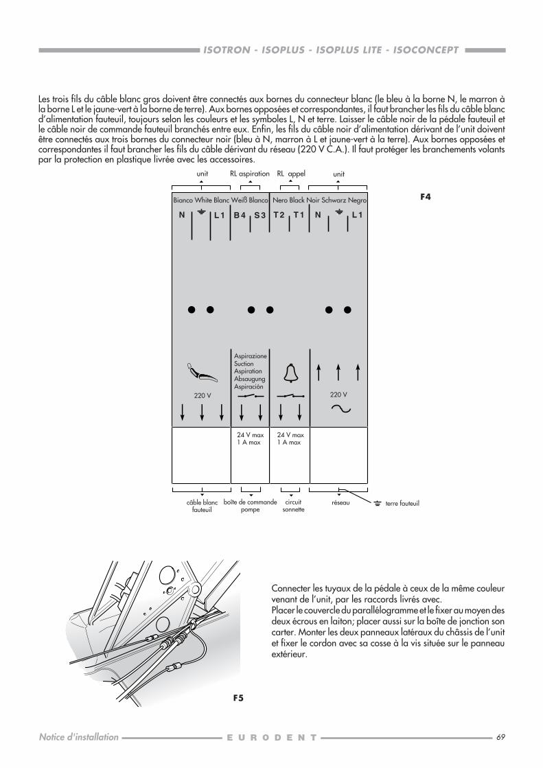
69
ISOTRON - ISOPLUS - ISOPLUS LITE - ISOCONCEPT
Notice d'installation
Les trois fils du câble blanc gros doivent être connectés aux bornes du connecteur blanc (le bleu à la borne N, le marron àla borne L et le jaune-vert à la borne de terre). Aux bornes opposées et correspondantes, il faut brancher les fils du câble blancd’alimentation fauteuil, toujours selon les couleurs et les symboles L, N et terre. Laisser le câble noir de la pédale fauteuil etle câble noir de commande fauteuil branchés entre eux. Enfin, les fils du câble noir d’alimentation dérivant de l’unit doiventêtre connectés aux trois bornes du connecteur noir (bleu à N, marron à L et jaune-vert à la terre). Aux bornes opposées etcorrespondantes il faut brancher les fils du câble dérivant du réseau (220 V C.A.). Il faut protéger les branchements volantspar la protection en plastique livrée avec les accessoires.
F4
Connecter les tuyaux de la pédale à ceux de la même couleurvenant de l’unit, par les raccords livrés avec.Placer le couvercle du parallélogramme et le fixer au moyen desdeux écrous en laiton; placer aussi sur la boîte de jonction soncarter. Monter les deux panneaux latéraux du châssis de l’unitet fixer le cordon avec sa cosse à la vis située sur le panneauextérieur.
F5
220 V 220 V
N L 1 B 4 S 3 T 2 T 1 N L 1
Bianco White Blanc Weiß Blanco Nero Black Noir Schwarz Negro
AspirazioneSuctionAspirationAbsaugungAspiración
24 V max1 A max
24 V max1 A max
RL aspiration RL appel unitunit
boîte de commandepompe
câble blancfauteuil
circuitsonnette
réseau terre fauteuil
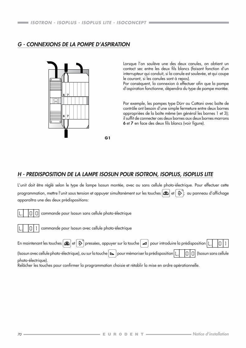
70
ISOTRON - ISOPLUS - ISOPLUS LITE - ISOCONCEPT
Notice d'installation
Lorsque l’on soulève une des deux canules, on obtient uncontact sec entre les deux fils blancs (faisant fonction d’uninterrupteur qui conduit, si la canule est soulevée, et qui coupele courant, si les canules sont à repos).Par conséquent, la connexion à effectuer afin que la pomped’aspiration fonctionne, dépendra du type de pompe montée.
Par exemple, les pompes type Dürr ou Cattani avec boîte decontrôle ont besoin d’une simple fermeture entre deux bornesappropriées de la boîte même (en général les bornes 1 et 3);il suffit de connecter ces deux bornes aux deux bornes marrons6 et 7 en face des deux fils blancs (voir figure).
6 7
6 7
G - CONNEXIONS DE LA POMPE D’ASPIRATION
H - PREDISPOSITION DE LA LAMPE ISOSUN POUR ISOTRON, ISOPLUS, ISOPLUS LITE
L’unit doit être réglé selon le type de lampe Isosun montée, avec ou sans cellule photo-électrique. Pour effectuer cette
programmation, mettre l’unit sous tension et appuyer simultanément sur les touches et ; au panneau d’affichage
apparaîtra une des deux prédispositions:
commande pour Isosun sans cellule photo-électrique
commande pour Isosun avec cellule photo-électrique
En maintenant les touches et pressées, appuyer sur la touche pour introduire la prédisposition
(Isosun avec cellule photo-électrique), ou sur la touche pour mémoriser la prédisposition (Isosun sans cellule
photo-électrique).Relâcher les touches pour confirmer la programmation choisie et rétablir la mise en ordre opérationnelle.
G1
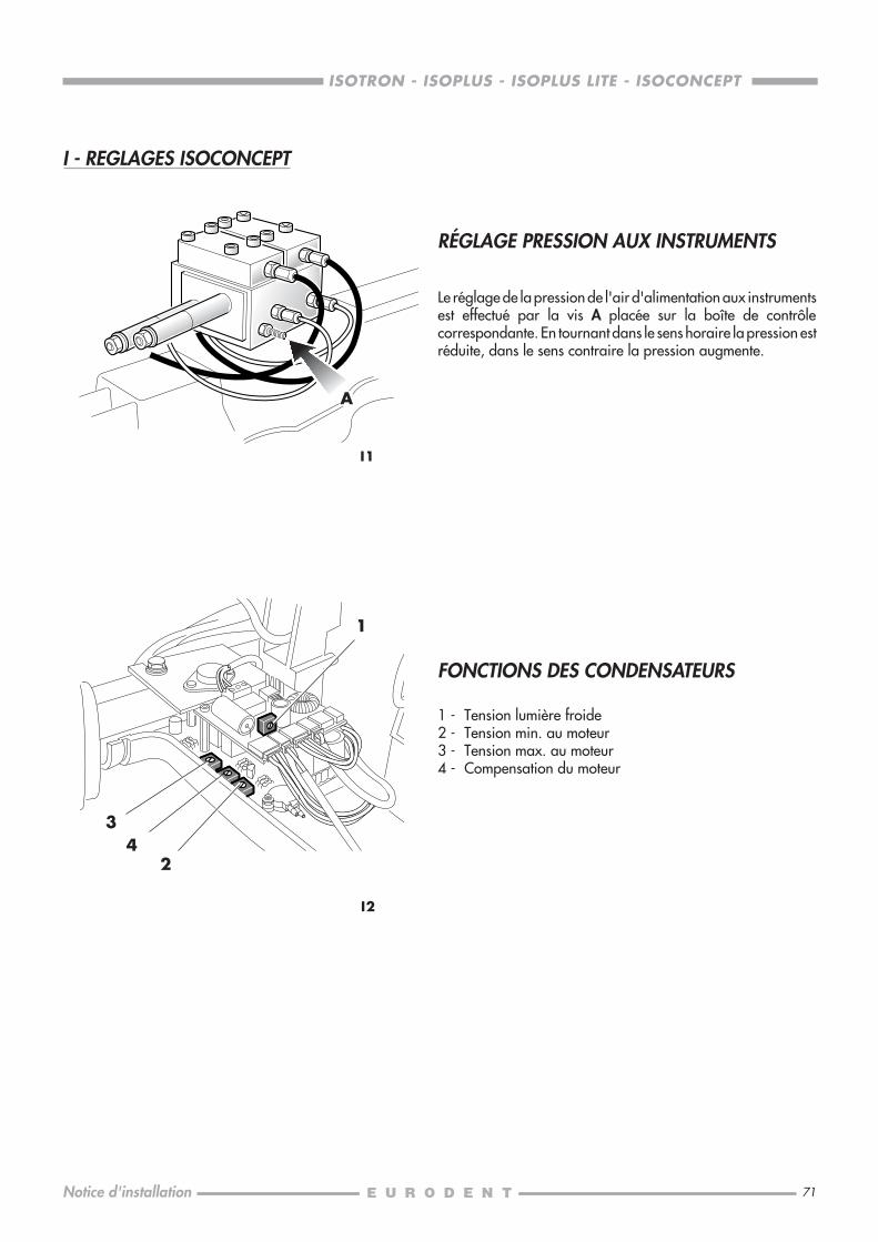
71
ISOTRON - ISOPLUS - ISOPLUS LITE - ISOCONCEPT
Notice d'installation
I2
FONCTIONS DES CONDENSATEURS
1 - Tension lumière froide2 - Tension min. au moteur3 - Tension max. au moteur4 - Compensation du moteur
1
34
I1
I - REGLAGES ISOCONCEPT
A
2
RÉGLAGE PRESSION AUX INSTRUMENTS
Le réglage de la pression de l'air d'alimentation aux instrumentsest effectué par la vis A placée sur la boîte de contrôlecorrespondante. En tournant dans le sens horaire la pression estréduite, dans le sens contraire la pression augmente.

73
ISOTRON - ISOPLUS - ISOPLUS LITE - ISOCONCEPT
Montageanleitung
VORBEMERKUNGEN............................................................................................... 74VERANTWORTUNGSERKLÄRUNG ...........................................................................74VORANORDNUNG.................................................................................................75
A VERPACKUNG DER ISORAMA UND ISO STÜHLE .................................................. 76TRANSPORT UND AUFSTELLEN...........................................................................77
B AUFSTELLEN DES ISORAMA-STUHLES ..................................................................78VORBEREITUNG .................................................................................................78FREISETZEN DER RÜCKENLEHNE ........................................................................ 78BEFESTIGEN DER RÜCKENLEHNE........................................................................ 78FUNKTIONSPRÜFUNG .......................................................................................79POLSTER DER RÜCKENLEHNE ............................................................................. 79POLSTER DES SITZES .......................................................................................... 80
C AUFSTELLEN DES ISO-STUHLES ............................................................................81RÜCKENLEHNE ..................................................................................................81RÜCKENLEHNE-POLSTERUNG ............................................................................ 81SITZ-POLSTERUNG .............................................................................................82MONTAGE DER ARMLEHNEN ............................................................................ 82
D KOPFSTÜTZE FÜR ISORAMA UND ISO STÜHLE .....................................................84
E AUFSTELLEN DER ISOTRON,ISOPLUS, ISOPLUS LITE, ISOCONCEPT BEHANDLUNGSEINHEITEN ................................ 85
F ELEKTRISCHE UND ELEKTROPNEUMATISCHE ANSCHLÜSSE...................................90ISOTRON, ISOPLUS, ISOPLUS LITE ....................................................................... 90ISOCONCEPT ....................................................................................................92
G ANSCHLUSS DER SAUGPUMPE ...........................................................................94
H VORANORDNUNG DER ISOSUN-DECKENLAMPE PER ISOTRON, ISOPLUS, ISOPLUS LITE ...... 94
I EINSTELLUNGEN DER ISOCONCEPT BEHANDLUNGSEINHEIT ..................................95DRUCKEINSTELLUNG BEI DEN INSTRUMENTEN .................................................. 95FUNKTIONEN DER TRIMMER ..............................................................................95
INHALT Seite

74
ISOTRON - ISOPLUS - ISOPLUS LITE - ISOCONCEPT
Montageanleitung
VORBEMERKUNGEN
Die aufzustellende Behandlungseinheit ist mit KLASSE I, mit angebrachten Teilen des Typs B ,
mit elektronischer Lanzette oder Elektrolanzette mit angebrachtem Teil des Typs BF gekennzeichnet (nur bei ISOTRON,
ISOPLUS, ISOPLUS LITE).
Klassierungsstellen (EN60 601-1):5.3 Gewöhnliche Geräte (Geräte, deren Verkleidung gegen Wassereindringen ungeschützt ist);5.5 Geräte, die für den Gebrauch bei anästhetischer, mit Luft oder Sauerstoff oder Stickstoffoxydul entzündbarer Mischung
ungeeignet sind;5.6 Geräte, die für Durchlaufbetrieb mit Aussetzbelastung bestimmt sind.
Leistung: 220 V / 50 Hz / 1350 VA (nur Behandlungseinheit: 550 VA) für ISOTRON, ISOPLUS, ISOPLUS LITE.220 V / 50 Hz / 1000 VA (nur Behandlungseinheit: 200 VA) für ISOCONCEPT.
Betriebsart: dauernd, mit aussetzender BelastungHöchste Aufzugsfähigkeit: 120 kg (ausschließlich Behandlungseinheit und Lampe)
Der Fußboden muß den DIN-Normen 1055 B1.3 und 18560 T1 entsprechen.
Ein äußerer, zweipoliger Hauptschalter, der den derzeit gültigen Normen entsprechen und folgende elektrische Eigenschaftenbesitzen soll: 250 V / 10 A, muß an der Wand installiert werden, um die Behandlungseinheit bei internem Eingriffauszuschalten.
Die elektrische Anlage muß den IEC-Normen 64.4 entsprechen und mit Differentialschutzleitern gefertigt sein (mit Index < 30mA) für 16 A/250 V.Die Erdung muß insbesondere dem Art. 3.2.01 der obengenannten Normen entsprechen.
Der Wasserdruck am Einlaß der Behandlungseinheit muß zwischen 1.8 und 3.0 bar liegen. Die Leitung muss einWasservolumen von mindestens 5 Liter/Min. zusichern.Die charakteristischen Merkmale des Wassers müssen die DIN-Normen 1988 erfüllen und der Wasserhärtegrad muß ≤ 8°dH liegen (also 1.432 mmol/Liter).Es wird empfohlen, ein Druckminderventil mit Hahn am Auslaß des Wasserschlauches (vorzugsweise mit Ø 15 mm)anzubauen.
Der vom Kompressor gelieferte Luftdruck muß zwischen 5.0 und 7.0 bar liegen. Einen Trockenkompressor mit 60 Liter/min.Luftabgabe bei 5 bar ist zu benutzen. Es empfiehlt sich, ein Hahn am Auslaß des Schlauches (vorzugsweise mit Ø 15 mm)zu installieren.
Der Ablaufschlauch muß eine 40 mm lichte Weite besitzen, die aber an der Tülle 32 mm betragen soll; der Abdachgradientmuß mindestens 1 cm/m sein und die Krümmungen dürfen nicht unter 135° liegen.
Der Einlaufschlauch muß eine 32/40 mm lichte Weite besitzen. Es empfiehlt sich, die vom Hersteller der Saugpumpegelieferten Anweisungen zu beachten.
Alle Voranordnungen sind gemäß den Hinweisen vorzunehmen, die auf nachfolgender Seite und in der jeder Behandlungseinheitbeigefügten Montagezeichnung (Maßstab 1:1) Kode 633580010 aufgeführt sind.
EURODENT empfiehlt für jegliche weitere technische Einzelheiten den Ersatzteil-Katalog nachzusehen und verpflichtet sich,den Kunden alle weiteren erforderlichen Auskünfte zu erteilen.
EURODENT übernimmt die Verantwortung für Sicherheit und Zuverlässigkeit des Gerätes nur wenn:• Aufstellungs-, Zusammenbau-, Erweiterungs-, Einstellungs- und Reparaturarbeiten von berechtigtem Personal ausgeführt
worden sind;• die generelle Aufstellung und die Elektroanlage des Raumes, der für den Arbeitsplatz bestimmt ist, mit entsprechenden
geltenden Vorschriften übereinstimmt;• das Gerät laut der "MONTAGEANLEITUNG" aufgestellt worden ist;• das Gerät laut der "BEDIENUNGSANLEITUNG" betrieben worden ist.
0051 Die Geräte stimmen mit den wesentlichen Anforderungen der EG-Richtlinie 93/42.
Schutzerdung
Achtung, beiliegende Dokumentation nachschlagen

75
ISOTRON - ISOPLUS - ISOPLUS LITE - ISOCONCEPT
Montageanleitung
VORANORDNUNG
..
.....
5060
175
E
A
A 3/8"G
20
B
C D
35
295
150
80
40
40 30
40
B
C
3/8"G
20
25
ø 32
ø 4
0
D
E
25
500
ø 32
ø 4
0
ISOSUN
A. Wasser: 3/8" G
B. Luft: 3/8" G
C. Ablauf: Ø 32
D. Absaugung: Ø 32
Pumpenanlassen: 2 x 1 mm2
E. Klingel: 2 x 0,5 mm2
Netz: 3 x 2,5 mm2
Bohrung zurBodenbefestigung
Bohrung zurBodenbefestigung
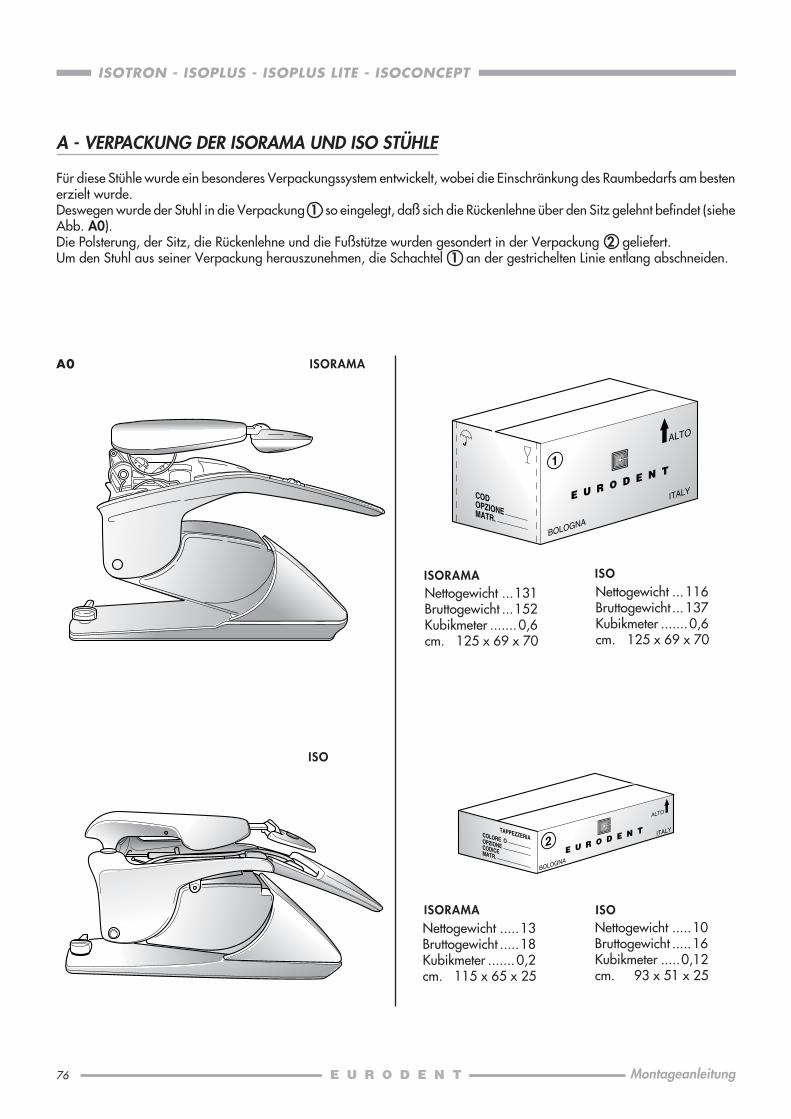
76
ISOTRON - ISOPLUS - ISOPLUS LITE - ISOCONCEPT
Montageanleitung
A0
1
ALTO
BOLOGNA
ITALYCOD OPZIONEMATR.
Nettogewicht ...131Bruttogewicht ...152Kubikmeter .......0,6cm. 125 x 69 x 70
2
ALTO
BOLOGNA
ITALYCOLORE OOPZIONE
TAPPEZZERIA
CODICEMATR.
A - VERPACKUNG DER ISORAMA UND ISO STÜHLE
Für diese Stühle wurde ein besonderes Verpackungssystem entwickelt, wobei die Einschränkung des Raumbedarfs am bestenerzielt wurde.Deswegen wurde der Stuhl in die Verpackung 1 so eingelegt, daß sich die Rückenlehne über den Sitz gelehnt befindet (sieheAbb. A0).Die Polsterung, der Sitz, die Rückenlehne und die Fußstütze wurden gesondert in der Verpackung 2 geliefert.Um den Stuhl aus seiner Verpackung herauszunehmen, die Schachtel 1 an der gestrichelten Linie entlang abschneiden.
ISORAMANettogewicht ... 116Bruttogewicht ... 137Kubikmeter .......0,6cm. 125 x 69 x 70
ISO
Nettogewicht .....13Bruttogewicht .....18Kubikmeter .......0,2cm. 115 x 65 x 25
ISORAMANettogewicht .....10Bruttogewicht .....16Kubikmeter .....0,12cm. 93 x 51 x 25
ISO
ISORAMA
ISO
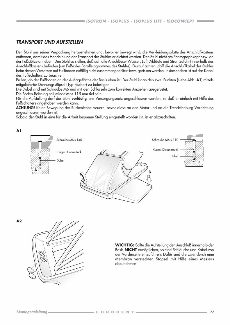
77
ISOTRON - ISOPLUS - ISOPLUS LITE - ISOCONCEPT
Montageanleitung
TRANSPORT UND AUFSTELLEN
Den Stuhl aus seiner Verpackung herausnehmen und, bevor er bewegt wird, die Verkleidungsplatte des Anschlußkastensentfernen, damit das Handeln und der Transport des Stuhles erleichtert werden. Den Stuhl nicht am Pantographkopf bzw. ander Fußstütze anheben. Den Stuhl so stellen, daß sich alle Anschlüsse (Wasser, Luft, Abläufe und Stromzufuhr) innerhalb desAnschlußkastens befinden (am Fuße des Parallelogrammes des Stuhles). Darauf achten, daß die Anschlußkabel des Stuhlesbeim dessen Versetzen auf Fußboden zufällig nicht zusammengedrückt bzw. gerissen werden. Insbesondere ist auf das Kabeldes Fußschalters zu beachten.Prüfen, ob der Fußboden an der Auflagefläche der Basis eben ist. Der Stuhl ist an den zwei Punkten (siehe Abb. A1) mittelsmitgelieferter Dehnungsstöpsel (Typ Fischer) zu befestigen.Die Dübel sind mit Schraube M6 und mit den Schlüsseln zum korrekten Anziehen ausgerüstet.Die Boden-Bohrung soll mindestens 115 mm tief sein.Für die Aufstellung darf der Stuhl vorläufig ans Versorgungsnetz angeschlossen werden, so daß er einfach mit Hilfe desFußschalters angehoben werden kann.ACHTUNG! Keine Bewegung der Rückenlehne steuern, bevor diese an den Motor und an die Trendelenburg-Vorrichtungangeschlossen worden ist.Sobald der Stuhl in eine für die Arbeit bequeme Stellung eingestellt worden ist, ist er abzuschalten.
A1
WICHTIG: Sollte die Aufstellung den Anschluß innerhalb derBasis NICHT ermöglichen, so sind Schläuche und Kabel vonder Vorderseite einzuführen. Dafür sind die zwei durch eineMembran versteckten Stöpsel mit Hilfe eines Messersabzunehmen.
A2
BAA
B
Schraube M6 x 140
Dübel
Langes Distanzstück
Schraube M6 x 110
Kurzes Distanzstück
Dübel

78
ISOTRON - ISOPLUS - ISOPLUS LITE - ISOCONCEPT
Montageanleitung
B1
B2
B3
B - AUFSTELLEN DES ISORAMA-STUHLES
VORBEREITUNG
Nachdem der Stuhl gestellt worden ist, ist die Armlehne durchLosmachen der zwei M6 Mutter mittels eines Schlüssels 10 mmzu entfernen.Die zwei Kunststoffbinden, welche die Schnecke desRückenlehnenmotors und die Trendelenburg-Zugstangezurückhalten, schneiden.
FREISETZEN DER RÜCKENLEHNE
Den M4 Dübel durch einen Inbusschlüssel 6 mm losmachen undden Zapfen der Rückenlehne aus seinem Sitz mittels desInbusschlüssels 6 mm entfernen.
Hinweis: Bitte die Zwischenlegscheibeberücksichtigen.
BEFESTIGEN DER RÜCKENLEHNE
Die Rückenlehne danach hochklappen, bis der Anschlußpunktund das Schneckenauge zusammenfallen, und den Zapfen derRückenlehne hineinstecken.
Mittels eines Inbusschlüssels fest anschrauben und danach umetwa 30° wieder losschrauben (weniger als eine Vierteldrehungdes Schlüssels), damit der Zapfen glatt dreht und mit wenigemSpiel.Danach durch Anziehen des M4 Dübels gut befestigen.Anschließend den Polysstyrolwürfel, der die Kopfstütze schützt,entfernen.
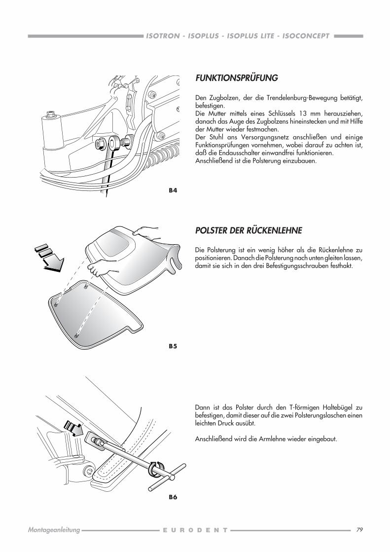
79
ISOTRON - ISOPLUS - ISOPLUS LITE - ISOCONCEPT
Montageanleitung
FUNKTIONSPRÜFUNG
Den Zugbolzen, der die Trendelenburg-Bewegung betätigt,befestigen.Die Mutter mittels eines Schlüssels 13 mm herausziehen,danach das Auge des Zugbolzens hineinstecken und mit Hilfeder Mutter wieder festmachen.Der Stuhl ans Versorgungsnetz anschließen und einigeFunktionsprüfungen vornehmen, wobei darauf zu achten ist,daß die Endausschalter einwandfrei funktionieren.Anschließend ist die Polsterung einzubauen.
B4
B6
B5
POLSTER DER RÜCKENLEHNE
Die Polsterung ist ein wenig höher als die Rückenlehne zupositionieren. Danach die Polsterung nach unten gleiten lassen,damit sie sich in den drei Befestigungsschrauben festhakt.
Dann ist das Polster durch den T-förmigen Haltebügel zubefestigen, damit dieser auf die zwei Polsterungslaschen einenleichten Druck ausübt.
Anschließend wird die Armlehne wieder eingebaut.
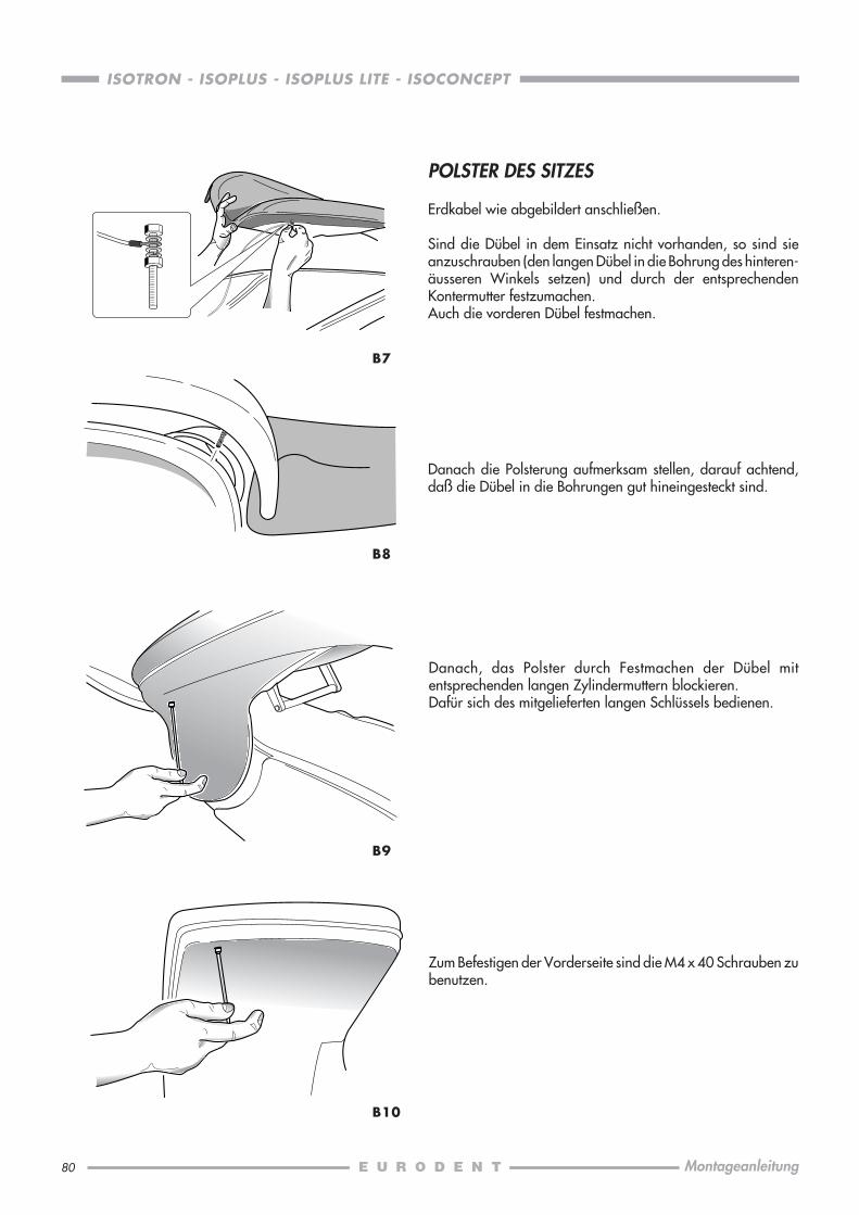
80
ISOTRON - ISOPLUS - ISOPLUS LITE - ISOCONCEPT
Montageanleitung
B8
B10
B7
B9
POLSTER DES SITZES
Erdkabel wie abgebildert anschließen.
Sind die Dübel in dem Einsatz nicht vorhanden, so sind sieanzuschrauben (den langen Dübel in die Bohrung des hinteren-äusseren Winkels setzen) und durch der entsprechendenKontermutter festzumachen.Auch die vorderen Dübel festmachen.
Danach die Polsterung aufmerksam stellen, darauf achtend,daß die Dübel in die Bohrungen gut hineingesteckt sind.
Danach, das Polster durch Festmachen der Dübel mitentsprechenden langen Zylindermuttern blockieren.Dafür sich des mitgelieferten langen Schlüssels bedienen.
Zum Befestigen der Vorderseite sind die M4 x 40 Schrauben zubenutzen.

81
ISOTRON - ISOPLUS - ISOPLUS LITE - ISOCONCEPT
Montageanleitung
C - AUFSTELLEN DES ISO-STUHLES
RÜCKENLEHNE
Die Schachtel längs der Strichlinie schneiden und den Stuhlauspacken. Die Rückenlehne wird gehoben, bis derAnschlußpunkt und die Stoßstange zusammenfallen. DiePaßscheibe aufmerksam hineinstecken, danach die Schraubeeinsetzen und gut anziehen.
Der Stuhl ist somit betriebsbereit. Es wird empfohlen, einigeBewegungen zur Prüfung des einwandfreien Funktionieren derEndmikroschalter durchzuführen.
Danach kann die Polsterung angebaut werden.
C2
RÜCKENLEHNE-POLSTERUNG
Die Polsterung wird oberhalb des Rückens gelegt und nachunten geschoben, so daß dieselbe in die zweiBefestigungsschrauben sorgfältig und fest einrastet.
Ist die Polsterung richtig positioniert, so ist die am Grund desgepolsterten Teils befindliche Schraube in die dafür vorgeseheneBohrung am Rücken hineinzustecken, beide Teile fest gedrücktzu halten und den Dübel M4 mittels eines 2mm-Inbusschlüsselsanzuziehen.
Sollte die Polsterung mit der Rückenlehne nicht genau passen,dann werden die zwei Senkkopfschrauben, wie schon bei derKopfstütze angegeben, entweder angezogen oder gelockert.
C3
C1

82
ISOTRON - ISOPLUS - ISOPLUS LITE - ISOCONCEPT
Montageanleitung
SITZ-POLSTERUNG
Die Polsterung wird auf den Sitz eingestellt und dann mit Hilfeder drei Schrauben M4, die unten vorspringen, befestigt.Die Muttern danach gut anziehen, um beide Teile festzusammenzubauen.
C4
MONTAGE DER ARMLEHNEN
Zuerst ist der fassonierte Stift Ø 8 ins Gehäuse der Rückenlehneeinzustecken. Dabei soll sich die Armlehne zu 90° im Verhältniszur Rückenlehne befinden: und zwar soll die gefräste Spitze desBolzens parallel zum Vorderprofil der Rückenlehne selbst sein.
C5
Wenn der Zapfen beim Umdrehen der Armlehne eingesetztbleibt, dann kann das Rückenlehneunterteil befestigt werden.
C6
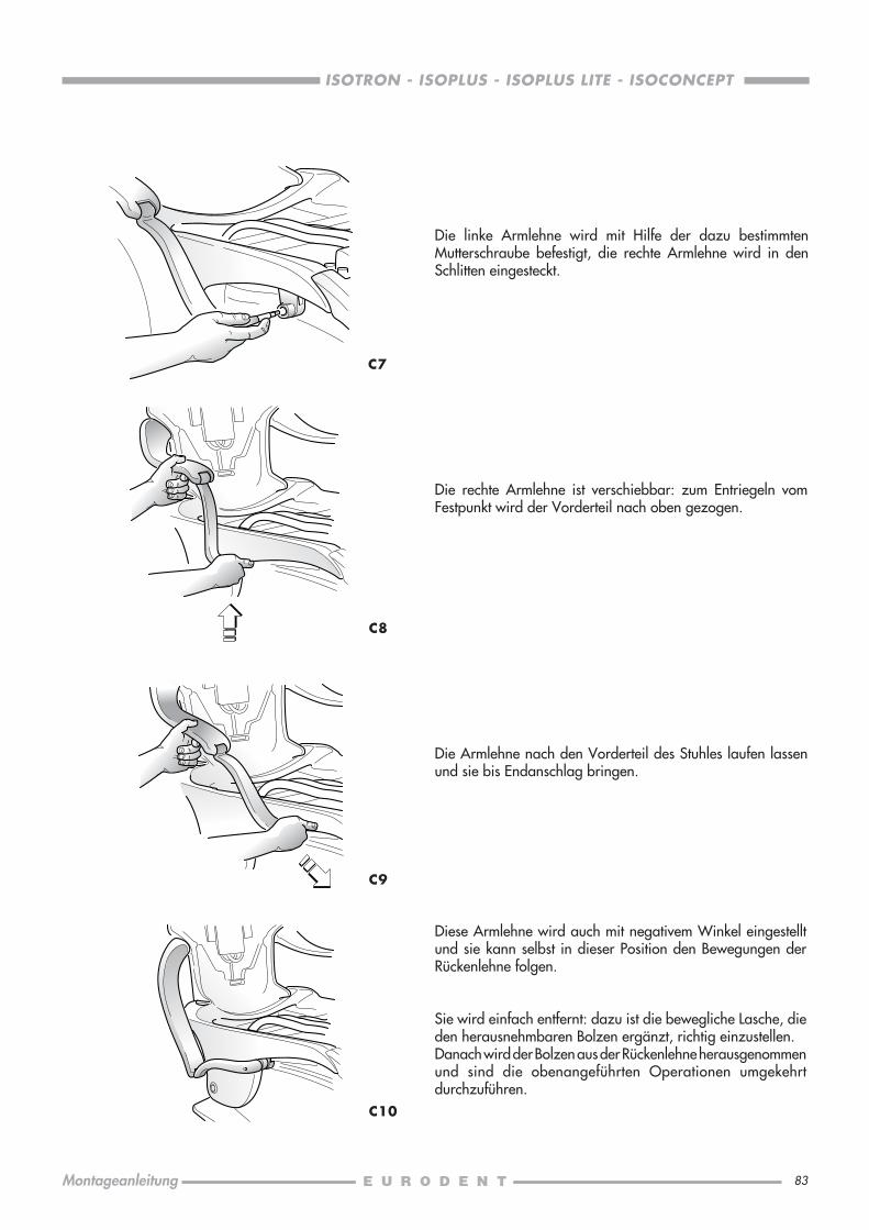
83
ISOTRON - ISOPLUS - ISOPLUS LITE - ISOCONCEPT
Montageanleitung
Die linke Armlehne wird mit Hilfe der dazu bestimmtenMutterschraube befestigt, die rechte Armlehne wird in denSchlitten eingesteckt.
C7
Die rechte Armlehne ist verschiebbar: zum Entriegeln vomFestpunkt wird der Vorderteil nach oben gezogen.
C8
C9
C10
Diese Armlehne wird auch mit negativem Winkel eingestelltund sie kann selbst in dieser Position den Bewegungen derRückenlehne folgen.
Sie wird einfach entfernt: dazu ist die bewegliche Lasche, dieden herausnehmbaren Bolzen ergänzt, richtig einzustellen.Danach wird der Bolzen aus der Rückenlehne herausgenommenund sind die obenangeführten Operationen umgekehrtdurchzuführen.
Die Armlehne nach den Vorderteil des Stuhles laufen lassenund sie bis Endanschlag bringen.

84
ISOTRON - ISOPLUS - ISOPLUS LITE - ISOCONCEPT
Montageanleitung
D2
D - KOPFSTÜTZE FÜR ISORAMA UND ISO STÜHLE
D1
Die Montage ist sehr einfach und offensichtlich:
Die Kopfstütze einstellen. Nachdem die Köpfe der beidenSchrauben hineingesteckt worden sind, wird nach untengedrückt und die zwei Dübel (die Stifte sind in denentsprechenden Öffnungen) werden eingeführt. DieBefestigungsstifte an den Seiten werden durch einen 2mmInbußschlüssel festgeschraubt, indem die zwei Teilegegeneinander gedrückt werden.
Um ein richtiges Zusammenpassen des Kissens mit dem Rückteilder Kopfstütze zu erlangen, muß man die zweiSenkkopfschrauben, die das Kissen festhalten, lockern bzw.anziehen.Nachdem die beiden Gegenmuttern gelockert worden sind,muß man die obenerwähnten Senkkopfschrauben so weit auf-bzw. zuschrauben, bis das Kissen genau paßt.
Danach sind die Gegenmuttern wieder anzuziehen.

85
ISOTRON - ISOPLUS - ISOPLUS LITE - ISOCONCEPT
Montageanleitung
E0
E1
E2
Außer dem Schutzdeckel des Anschlußkastens, wird esempfohlen, auch noch die Kappe des Parallelogrammes desStuhles abzunehmen, um die Einführung von Kabeln undSchläuchen der Behandlungseinheit zu erleichtern. Diese Kappewird einfach durch Lockern der zwei langen Messingmuttern,die sich unter der Kappe befinden und diese an den oberenStangen des Parallelogrammes anschrauben, abgenommen.Den Stuhl auf den Fußboden mit Hilfe der durch die Bohrungenauf der Vorderseite der Auflagefläche einzusteckendenDehnungsschrauben befestigen.
Danach ist das Gestell der Behandlungseinheit auf die Stützedes Stuhles mittels der mitgelieferten Stiftschrauben undInbusschrauben einzubauen (siehe die “AUSSTATTUNG”-Schachtel innerhalb der Verpackung der “BASIS”).
ISOTRON, ISOPLUS, ISOPLUS LITEAnschließend das Gestell senkrecht und waagerechtordnungsgemäß vor Festziehen der Schrauben und Mutternausgleichen; die Stiftschrauben sind in die niedrigeren, dieSchrauben in die höheren Bohrungen hineinzustecken.
ISOCONCEPTDazu ist die zweite mitgelieferte Stiftschraube zu verwenden:diese wird, sowie die erste, in die vorgesehenen Bohrungen aufniedrigerem Teil des Stuhles befestigt.Anschließend die Speifontäne senkrecht und waagerechtordnungsgemäß vor Festziehen der beiden Schrauben und derMittelmutter ausgleichen; die Sechskantsstiftschraube ausuntersten Bohrung entfernen und sie durch die dritte mitgelieferteSchraube ersetzen.
Kubikmeter ...... 0,555cm. 96 x 89 x 65
Nettogewicht ......... 22Bruttogewicht ......... 33
Kubikmeter ...... 0,428cm. 88 x 76 x 64
E - AUFSTELLEN DER ISOTRON, ISOPLUS, ISOPLUS LITE, ISOCONCEPT BEHANDLUNGSEINHEITEN
Nettogewicht ......... 71Bruttogewicht ......... 88
Kubikmeter ...... 0,555cm. 96 x 89 x 65
ISOTRONISOPLUS
ISOPLUS LITEISOCONCEPT
Kubikmeter ........... 0,428cm. 88 x 76 x 64
"BASIS"
"INSTRUMENTENPLATTE"
Nettogewicht ......... 46Bruttogewicht ......... 65
Nettogewicht ......... 18Bruttogewicht ......... 30
Die Behandlungseinheit wird in zwei verschiedenenVerpackungen geliefert, wovon die eine mit Zettel “BASIS” dasGestell und die Helferineinheit enthält und die andere mit Zettel“INSTRUMENTENPLATTE” die Zahnarzteinheit mitRückführungsarmen, verschiedene Module und den Trayhalterenthält.An den Wasser- und Luftstutzen ist der Einsatz von Hähnenerforderlich.Es ist notwendig, die Wasser- und Luftleitungen auszuräumen,bevor die Behandlungseinheit damit verbunden wird.
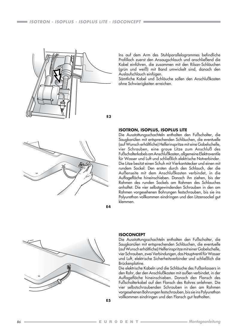
86
ISOTRON - ISOPLUS - ISOPLUS LITE - ISOCONCEPT
Montageanleitung
E3
ISOTRON, ISOPLUS, ISOPLUS LITEDie Ausstattungsschachteln enthalten den Fußschalter, dieSaugkanülen mit entsprechenden Schläuchen, die eventuelle(auf Wunsch erhältliche) Helferinspritze mit eine Gabelschelle,vier Schrauben, eine graue Litze zum Anschluß desFußschalterkabels am Anschlußkasten, allgemeine Elektroventilefür Wasser und Luft und schließlich elektrische Notverbinder.Die Litze besitzt einen Schuh mit Vierkantstecker und einen mitrundem Sockel: Den ersten durch den Schlauch, der dieAußenseite mit dem Anschlußkasten verbindet, in dieAuflagefläche hineinschieben. Danach ihn ziehen, bis derRahmen des runden Sockels am Rahmen des Schlauchesanhaftet. Die vier selbstgewindenden Schrauben in den amRahmen vorgesehenen Bohrungen festschrauben, bis sie insPolyurethan vollkommen eindringen und den Litzensockel gutklemmen.
E4
ISOCONCEPTDie Ausstattungsschachteln enthalten den Fußschalter, dieSaugkanülen mit entsprechenden Schläuchen, die eventuelle(auf Wunsch erhältliche) Helferinspritze mit einer Gabelschelle,vier Schrauben, zwei Verbindungen, das Hauptventil für Wasserund Luft, elektrische Sicherheitsverbinder und schließlich dieBrückenplatine.Die elektrische Kabeln und die Schläuche des Fußanlassers inden Rohr, der den Anschlußkasten mit außen verbindet, in derAuflagefläche hineinschieben. Danach den Flansch desFußschalterkabel auf den Flansch des Rohres anlehnen. Dievier selbstschraubenden Schrauben in den am Rahmenvorgesehenen Bohrungen festschrauben, bis sie ins Polyurethanvollkommen eindringen und den Flansch gut festhalten.
E5
Ins auf dem Arm des Stuhlparallelogrammes befindlicheProfilloch zuerst den Ansaugschlauch und anschließend dieKabel einführen, die zusammen mit den Rilsan-Schläuchen(grün und weiß) mit Band umwickelt sind, danach denAuslaufschlauch einfügen.Sämtliche Kabel und Schläuche sollen den Anschlußkastenohne Schwierigkeiten erreichen.
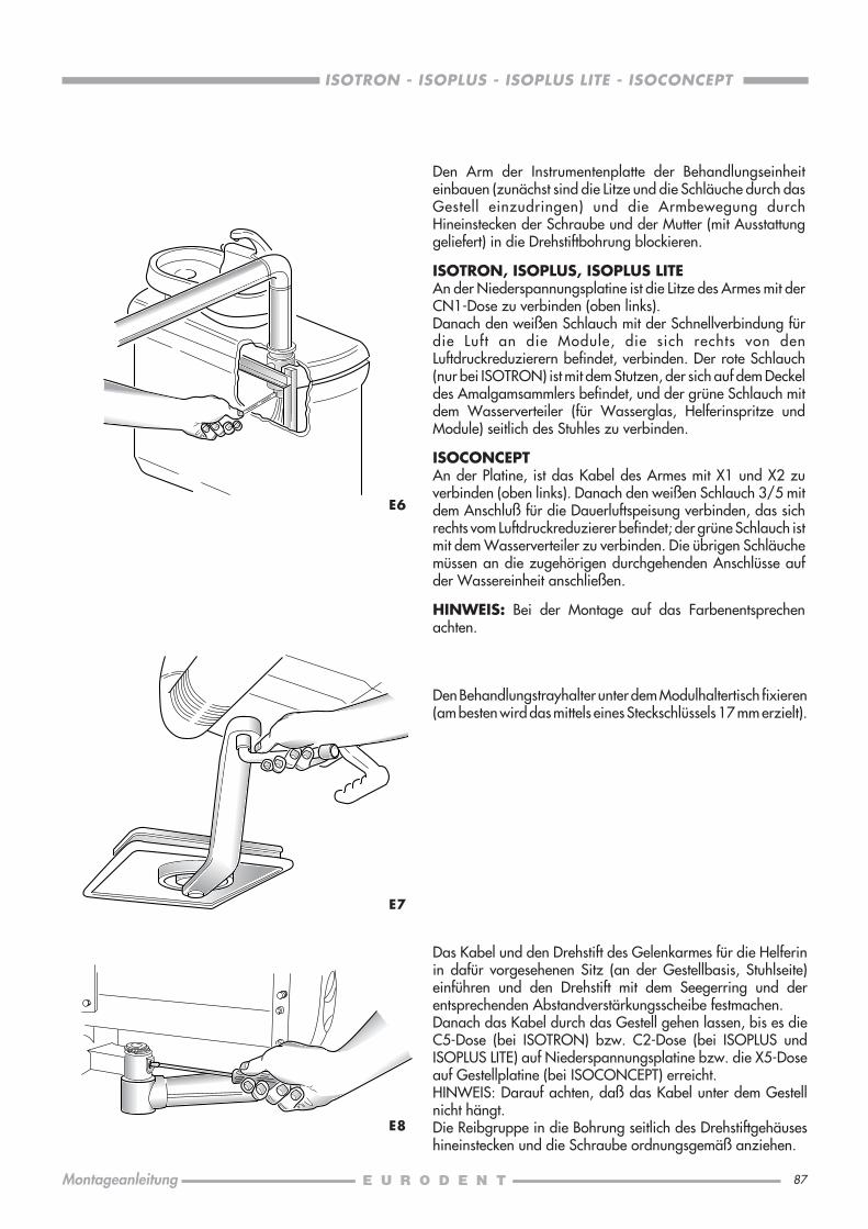
87
ISOTRON - ISOPLUS - ISOPLUS LITE - ISOCONCEPT
Montageanleitung
Den Arm der Instrumentenplatte der Behandlungseinheiteinbauen (zunächst sind die Litze und die Schläuche durch dasGestell einzudringen) und die Armbewegung durchHineinstecken der Schraube und der Mutter (mit Ausstattunggeliefert) in die Drehstiftbohrung blockieren.
ISOTRON, ISOPLUS, ISOPLUS LITEAn der Niederspannungsplatine ist die Litze des Armes mit derCN1-Dose zu verbinden (oben links).Danach den weißen Schlauch mit der Schnellverbindung fürdie Luft an die Module, die sich rechts von denLuftdruckreduzierern befindet, verbinden. Der rote Schlauch(nur bei ISOTRON) ist mit dem Stutzen, der sich auf dem Deckeldes Amalgamsammlers befindet, und der grüne Schlauch mitdem Wasserverteiler (für Wasserglas, Helferinspritze undModule) seitlich des Stuhles zu verbinden.
ISOCONCEPTAn der Platine, ist das Kabel des Armes mit X1 und X2 zuverbinden (oben links). Danach den weißen Schlauch 3/5 mitdem Anschluß für die Dauerluftspeisung verbinden, das sichrechts vom Luftdruckreduzierer befindet; der grüne Schlauch istmit dem Wasserverteiler zu verbinden. Die übrigen Schläuchemüssen an die zugehörigen durchgehenden Anschlüsse aufder Wassereinheit anschließen.
HINWEIS: Bei der Montage auf das Farbenentsprechenachten.
E6
E7
E8
Den Behandlungstrayhalter unter dem Modulhaltertisch fixieren(am besten wird das mittels eines Steckschlüssels 17 mm erzielt).
Das Kabel und den Drehstift des Gelenkarmes für die Helferinin dafür vorgesehenen Sitz (an der Gestellbasis, Stuhlseite)einführen und den Drehstift mit dem Seegerring und derentsprechenden Abstandverstärkungsscheibe festmachen.Danach das Kabel durch das Gestell gehen lassen, bis es dieC5-Dose (bei ISOTRON) bzw. C2-Dose (bei ISOPLUS undISOPLUS LITE) auf Niederspannungsplatine bzw. die X5-Doseauf Gestellplatine (bei ISOCONCEPT) erreicht.HINWEIS: Darauf achten, daß das Kabel unter dem Gestellnicht hängt.Die Reibgruppe in die Bohrung seitlich des Drehstiftgehäuseshineinstecken und die Schraube ordnungsgemäß anziehen.

88
ISOTRON - ISOPLUS - ISOPLUS LITE - ISOCONCEPT
Montageanleitung
E9
ISOTRONIst die Behandlungseinheit mit der Spritze für die Helferinausgerüstet, so muß man wie folgt vorgehen:Den Spritzenschlauch ins dazu bestimmte Gehäuse auf demKanülenträger einfügen und ihn von oben nach unten durchdas Loch zwischen Saugfilter und Kanülenabspülungsbehältereinführen, danach dessen Endbuchse durch die mitgelieferteGabelschelle fixieren. Die Schrauben, die zur Befestigung desDeckels des Platinenkastens für die 6-Zwecksspritze dienen,abschrauben. Dieser Kasten befindet sich auf demSaugabspülungsbehälter. Dann die Schläuche und die Drähtedes Spritzenschlauches verbinden und den Deckel wiederschließen.Die Saugrohre in die dazugehörigen Sitze auf demKanülenträger einführen und deren Stutzen in dieentsprechenden Kuppelbuchsen einschalten.
E10
ISOPLUS, ISOPLUS LITEIst die Behandlungseinheit mit der Spritze für die Helferinausgerüstet, so muß man wie folgt vorgehen:Den Spritzenschlauch ins dazu bestimmte Gehäuse auf demKanülenträger einfügen und ihn von oben nach unten durchdas Loch zwischen Saugfilter und Kanülenabspülungsbehältereinführen, danach dessen Endbuchse durch die mitgelieferteGabelschelle fixieren.Luft- und Wasserschlauch der Spritzenschnur an dieentsprechenden, neben dem Saugfilter befindlichen Schläucheanschließen.Die Saugrohre in die dazugehörigen Sitze auf demKanülenträger einführen und deren Stutzen in dieentsprechenden Kuppelbuchsen einschalten.
E11
ISOCONCEPTIst die Behandlungseinheit mit der Spritze für die Helferinausgerüstet, so muß man wie folgt vorgehen:Den Spritzenschlauch in die dazu bestimmte Bohrung links vomSaugfilter einFügen, danach dessen Endbuchse durch diemitgelieferte Gabelschelle fixieren.Wasserschlauch an den entsprechenden, neben dem Saugfilterbefindlichen Schlauch anschließen.Luftschlauch an Spritzenluftreduzierer anschließen.
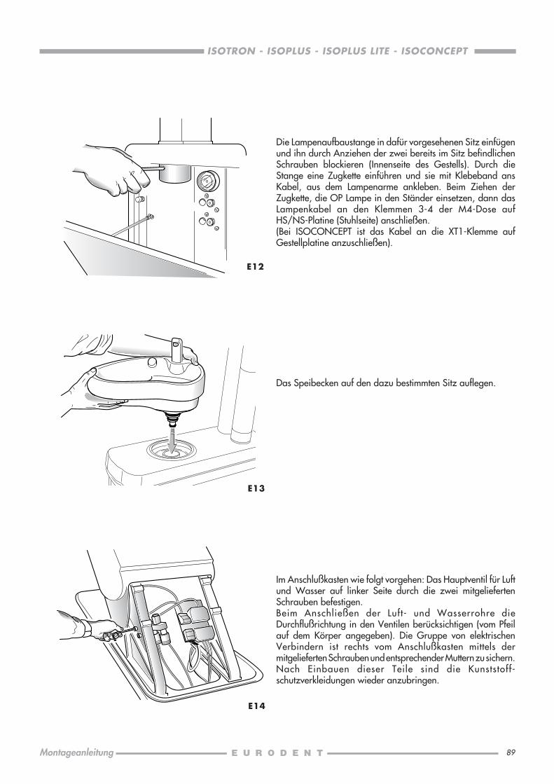
89
ISOTRON - ISOPLUS - ISOPLUS LITE - ISOCONCEPT
Montageanleitung
E12
E13
Im Anschlußkasten wie folgt vorgehen: Das Hauptventil für Luftund Wasser auf linker Seite durch die zwei mitgeliefertenSchrauben befestigen.Beim Anschließen der Luft- und Wasserrohre dieDurchflußrichtung in den Ventilen berücksichtigen (vom Pfeilauf dem Körper angegeben). Die Gruppe von elektrischenVerbindern ist rechts vom Anschlußkasten mittels dermitgelieferten Schrauben und entsprechender Muttern zu sichern.Nach Einbauen dieser Teile sind die Kunststoff-schutzverkleidungen wieder anzubringen.
Die Lampenaufbaustange in dafür vorgesehenen Sitz einfügenund ihn durch Anziehen der zwei bereits im Sitz befindlichenSchrauben blockieren (Innenseite des Gestells). Durch dieStange eine Zugkette einführen und sie mit Klebeband ansKabel, aus dem Lampenarme ankleben. Beim Ziehen derZugkette, die OP Lampe in den Ständer einsetzen, dann dasLampenkabel an den Klemmen 3-4 der M4-Dose aufHS/NS-Platine (Stuhlseite) anschließen.(Bei ISOCONCEPT ist das Kabel an die XT1-Klemme aufGestellplatine anzuschließen).
E14
Das Speibecken auf den dazu bestimmten Sitz auflegen.
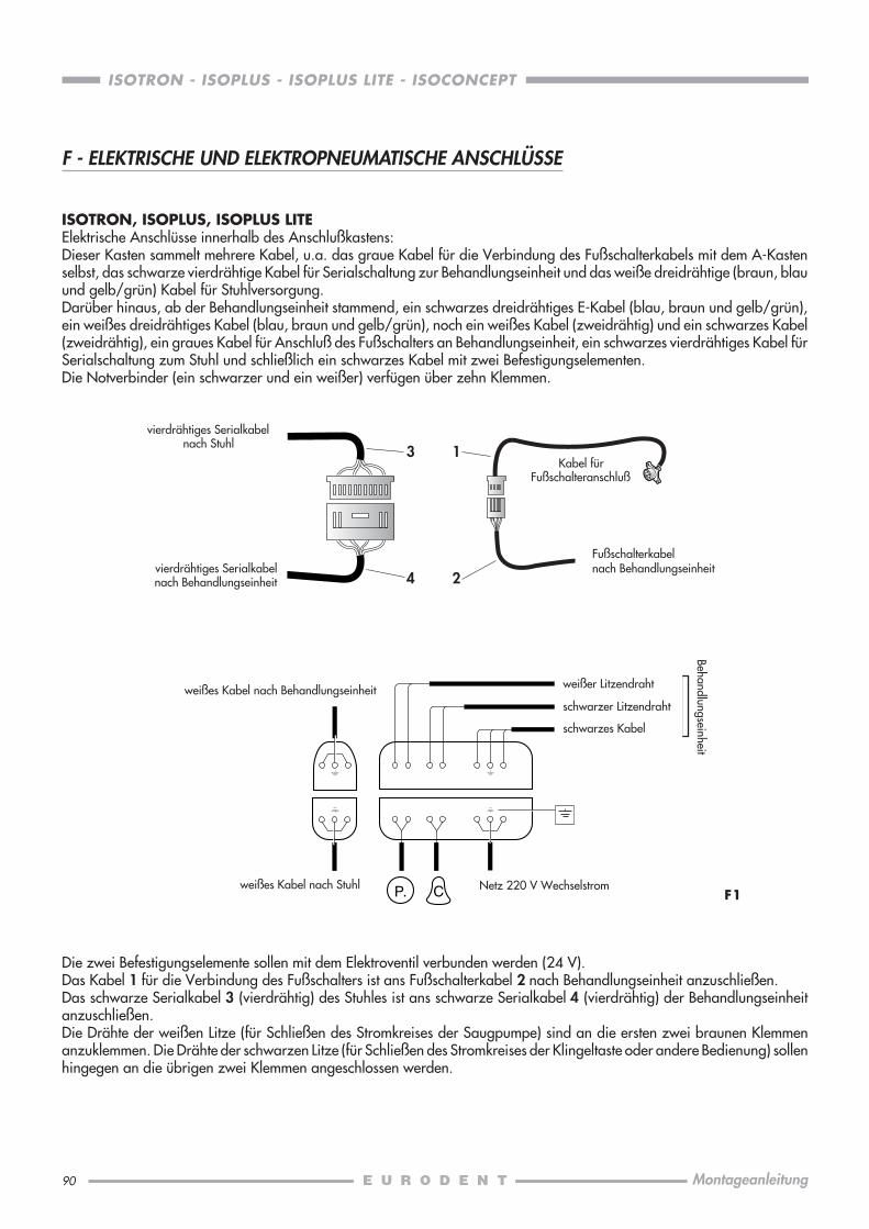
90
ISOTRON - ISOPLUS - ISOPLUS LITE - ISOCONCEPT
Montageanleitung
F - ELEKTRISCHE UND ELEKTROPNEUMATISCHE ANSCHLÜSSE
ISOTRON, ISOPLUS, ISOPLUS LITEElektrische Anschlüsse innerhalb des Anschlußkastens:Dieser Kasten sammelt mehrere Kabel, u.a. das graue Kabel für die Verbindung des Fußschalterkabels mit dem A-Kastenselbst, das schwarze vierdrähtige Kabel für Serialschaltung zur Behandlungseinheit und das weiße dreidrähtige (braun, blauund gelb/grün) Kabel für Stuhlversorgung.Darüber hinaus, ab der Behandlungseinheit stammend, ein schwarzes dreidrähtiges E-Kabel (blau, braun und gelb/grün),ein weißes dreidrähtiges Kabel (blau, braun und gelb/grün), noch ein weißes Kabel (zweidrähtig) und ein schwarzes Kabel(zweidrähtig), ein graues Kabel für Anschluß des Fußschalters an Behandlungseinheit, ein schwarzes vierdrähtiges Kabel fürSerialschaltung zum Stuhl und schließlich ein schwarzes Kabel mit zwei Befestigungselementen.Die Notverbinder (ein schwarzer und ein weißer) verfügen über zehn Klemmen.
P. C F1
3
4
1
2
vierdrähtiges Serialkabelnach Stuhl
vierdrähtiges Serialkabelnach Behandlungseinheit
Kabel fürFußschalteranschluß
weißer Litzendraht
schwarzes Kabel
weißes Kabel nach Stuhl Netz 220 V Wechselstrom
weißes Kabel nach Behandlungseinheit
Fußschalterkabelnach Behandlungseinheit
Behandlungseinheit
schwarzer Litzendraht
Die zwei Befestigungselemente sollen mit dem Elektroventil verbunden werden (24 V).Das Kabel 1 für die Verbindung des Fußschalters ist ans Fußschalterkabel 2 nach Behandlungseinheit anzuschließen.Das schwarze Serialkabel 3 (vierdrähtig) des Stuhles ist ans schwarze Serialkabel 4 (vierdrähtig) der Behandlungseinheitanzuschließen.Die Drähte der weißen Litze (für Schließen des Stromkreises der Saugpumpe) sind an die ersten zwei braunen Klemmenanzuklemmen. Die Drähte der schwarzen Litze (für Schließen des Stromkreises der Klingeltaste oder andere Bedienung) sollenhingegen an die übrigen zwei Klemmen angeschlossen werden.
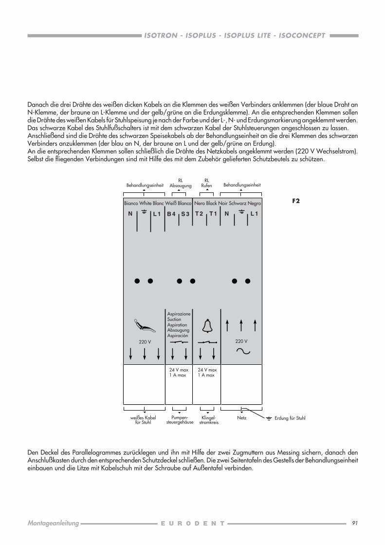
91
ISOTRON - ISOPLUS - ISOPLUS LITE - ISOCONCEPT
Montageanleitung
220 V 220 V
N L 1 B 4 S 3 T 2 T 1 N L 1
F2Bianco White Blanc Weiß Blanco Nero Black Noir Schwarz Negro
AspirazioneSuctionAspirationAbsaugungAspiración
24 V max1 A max
24 V max1 A max
Danach die drei Drähte des weißen dicken Kabels an die Klemmen des weißen Verbinders anklemmen (der blaue Draht anN-Klemme, der braune an L-Klemme und der gelb/grüne an die Erdungsklemme). An die entsprechenden Klemmen sollendie Drähte des weißen Kabels für Stuhlspeisung je nach der Farbe und der L-, N- und Erdungsmarkierung angeklemmt werden.Das schwarze Kabel des Stuhlfußschalters ist mit dem schwarzen Kabel der Stuhlsteuerungen angeschlossen zu lassen.Anschließend sind die Drähte des schwarzen Speisekabels ab der Behandlungseinheit an die drei Klemmen des schwarzenVerbinders anzuklemmen (der blau an N, der braune an L und der gelb/grüne an Erdung).An die entsprechenden Klemmen sollen schließlich die Drähte des Netzkabels angeklemmt werden (220 V Wechselstrom).Selbst die fliegenden Verbindungen sind mit Hilfe des mit dem Zubehör gelieferten Schutzbeutels zu schützen.
Den Deckel des Parallelogrammes zurücklegen und ihn mit Hilfe der zwei Zugmuttern aus Messing sichern, danach denAnschlußkasten durch den entsprechenden Schutzdeckel schließen. Die zwei Seitentafeln des Gestells der Behandlungseinheiteinbauen und die Litze mit Kabelschuh mit der Schraube auf Außentafel verbinden.
RLAbsaugung
RLRufen BehandlungseinheitBehandlungseinheit
Netz Erdung für Stuhlweißes Kabelfür Stuhl
Pumpen-steuergehäuse
Klingel-stromkreis
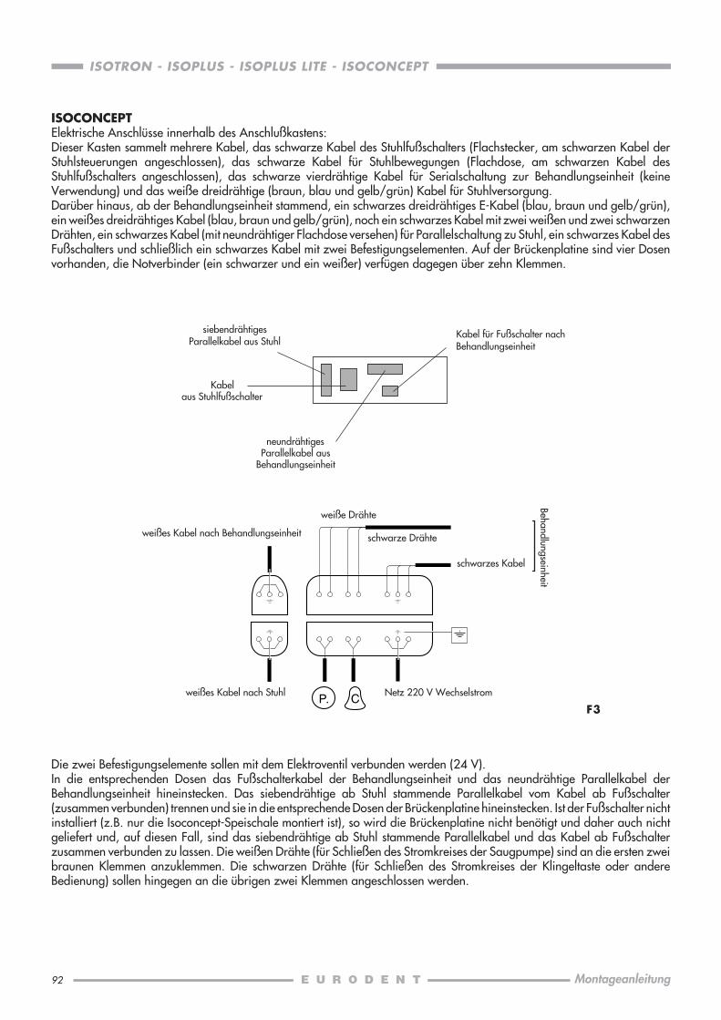
92
ISOTRON - ISOPLUS - ISOPLUS LITE - ISOCONCEPT
Montageanleitung
Die zwei Befestigungselemente sollen mit dem Elektroventil verbunden werden (24 V).In die entsprechenden Dosen das Fußschalterkabel der Behandlungseinheit und das neundrähtige Parallelkabel derBehandlungseinheit hineinstecken. Das siebendrähtige ab Stuhl stammende Parallelkabel vom Kabel ab Fußschalter(zusammen verbunden) trennen und sie in die entsprechende Dosen der Brückenplatine hineinstecken. Ist der Fußschalter nichtinstalliert (z.B. nur die Isoconcept-Speischale montiert ist), so wird die Brückenplatine nicht benötigt und daher auch nichtgeliefert und, auf diesen Fall, sind das siebendrähtige ab Stuhl stammende Parallelkabel und das Kabel ab Fußschalterzusammen verbunden zu lassen. Die weißen Drähte (für Schließen des Stromkreises der Saugpumpe) sind an die ersten zweibraunen Klemmen anzuklemmen. Die schwarzen Drähte (für Schließen des Stromkreises der Klingeltaste oder andereBedienung) sollen hingegen an die übrigen zwei Klemmen angeschlossen werden.
ISOCONCEPTElektrische Anschlüsse innerhalb des Anschlußkastens:Dieser Kasten sammelt mehrere Kabel, das schwarze Kabel des Stuhlfußschalters (Flachstecker, am schwarzen Kabel derStuhlsteuerungen angeschlossen), das schwarze Kabel für Stuhlbewegungen (Flachdose, am schwarzen Kabel desStuhlfußschalters angeschlossen), das schwarze vierdrähtige Kabel für Serialschaltung zur Behandlungseinheit (keineVerwendung) und das weiße dreidrähtige (braun, blau und gelb/grün) Kabel für Stuhlversorgung.Darüber hinaus, ab der Behandlungseinheit stammend, ein schwarzes dreidrähtiges E-Kabel (blau, braun und gelb/grün),ein weißes dreidrähtiges Kabel (blau, braun und gelb/grün), noch ein schwarzes Kabel mit zwei weißen und zwei schwarzenDrähten, ein schwarzes Kabel (mit neundrähtiger Flachdose versehen) für Parallelschaltung zu Stuhl, ein schwarzes Kabel desFußschalters und schließlich ein schwarzes Kabel mit zwei Befestigungselementen. Auf der Brückenplatine sind vier Dosenvorhanden, die Notverbinder (ein schwarzer und ein weißer) verfügen dagegen über zehn Klemmen.
F3P. C
weiße Drähte
schwarzes Kabel
weißes Kabel nach Stuhl Netz 220 V Wechselstrom
Behandlungseinheit
Kabel für Fußschalter nachBehandlungseinheit
weißes Kabel nach Behandlungseinheit
siebendrähtigesParallelkabel aus Stuhl
Kabelaus Stuhlfußschalter
neundrähtigesParallelkabel aus
Behandlungseinheit
schwarze Drähte

93
ISOTRON - ISOPLUS - ISOPLUS LITE - ISOCONCEPT
Montageanleitung
F4
F5
220 V 220 V
N L 1 B 4 S 3 T 2 T 1 N L 1
Bianco White Blanc Weiß Blanco Nero Black Noir Schwarz Negro
AspirazioneSuctionAspirationAbsaugungAspiración
24 V max1 A max
24 V max1 A max
Danach die drei Drähte des weißen dicken Kabels an die Klemmen des weißen Verbinders anklemmen (der blaue Draht anN-Klemme, der braune an L-Klemme und der gelb/grüne an die Erdungsklemme). An die entsprechenden Klemmen sollendie Drähte des weißen Kabels für Stuhlspeisung je nach der Farbe und der L-, N- und Erdungsmarkierung angeklemmt werden.Das schwarze Kabel des Stuhlfußschalters ist mit dem schwarzen Kabel der Stuhlsteuerungen angeschlossen zu lassen.Anschließend sind die Drähte des schwarzen Speisekabels ab der Behandlungseinheit an die drei Klemmen des schwarzenVerbinders anzuklemmen (der blau an N, der braune an L und der gelb/grüne an Erdung).An die entsprechenden Klemmen sollen schließlich die Drähte des Netzkabels angeklemmt werden (220 V Wechselstrom).Selbst die fliegenden Verbindungen sind mit Hilfe des mit dem Zubehör gelieferten Schutzbeutels zu schützen.
RLAbsaugung
RLRufen BehandlungseinheitBehandlungseinheit
Netz Erdung für Stuhlweißes Kabelfür Stuhl
Pumpen-steuergehäuse
Klingel-stromkreis
Die Schläuche des Fußschalters nach Schlauchfarben mit denentsprechenden Verbindungen anschließen.Den Deckel des Parallelogrammes zurücklegen und ihn mitHilfe der zwei Zugmuttern aus Messing sichern, danach denAnschlußkasten durch den entsprechenden Schutzdeckelschließen. Die zwei Seitentafeln des Gestells derBehandlungseinheit einbauen und die Litze mit Kabelschuh mitder Schraube auf Außentafel verbinden.
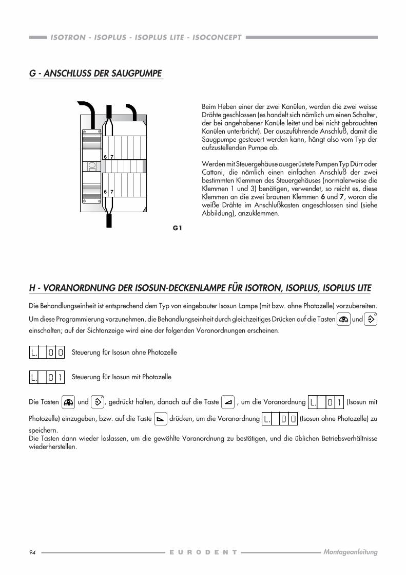
94
ISOTRON - ISOPLUS - ISOPLUS LITE - ISOCONCEPT
Montageanleitung
6 7
6 7
G - ANSCHLUSS DER SAUGPUMPE
H - VORANORDNUNG DER ISOSUN-DECKENLAMPE FÜR ISOTRON, ISOPLUS, ISOPLUS LITE
Die Behandlungseinheit ist entsprechend dem Typ von eingebauter Isosun-Lampe (mit bzw. ohne Photozelle) vorzubereiten.
Um diese Programmierung vorzunehmen, die Behandlungseinheit durch gleichzeitiges Drücken auf die Tasten und
einschalten; auf der Sichtanzeige wird eine der folgenden Voranordnungen erscheinen.
Steuerung für Isosun ohne Photozelle
Steuerung für Isosun mit Photozelle
Die Tasten und , gedrückt halten, danach auf die Taste , um die Voranordnung (Isosun mit
Photozelle) einzugeben, bzw. auf die Taste drücken, um die Voranordnung (Isosun ohne Photozelle) zu
speichern.Die Tasten dann wieder loslassen, um die gewählte Voranordnung zu bestätigen, und die üblichen Betriebsverhältnissewiederherstellen.
G1
Beim Heben einer der zwei Kanülen, werden die zwei weisseDrähte geschlossen (es handelt sich nämlich um einen Schalter,der bei angehobener Kanüle leitet und bei nicht gebrauchtenKanülen unterbricht). Der auszuführende Anschluß, damit dieSaugpumpe gesteuert werden kann, hängt also vom Typ deraufzustellenden Pumpe ab.
Werden mit Steuergehäuse ausgerüstete Pumpen Typ Dürr oderCattani, die nämlich einen einfachen Anschluß der zweibestimmten Klemmen des Steuergehäuses (normalerweise dieKlemmen 1 und 3) benötigen, verwendet, so reicht es, dieseKlemmen an die zwei braunen Klemmen 6 und 7, woran dieweiße Drähte im Anschlußkasten angeschlossen sind (sieheAbbildung), anzuklemmen.
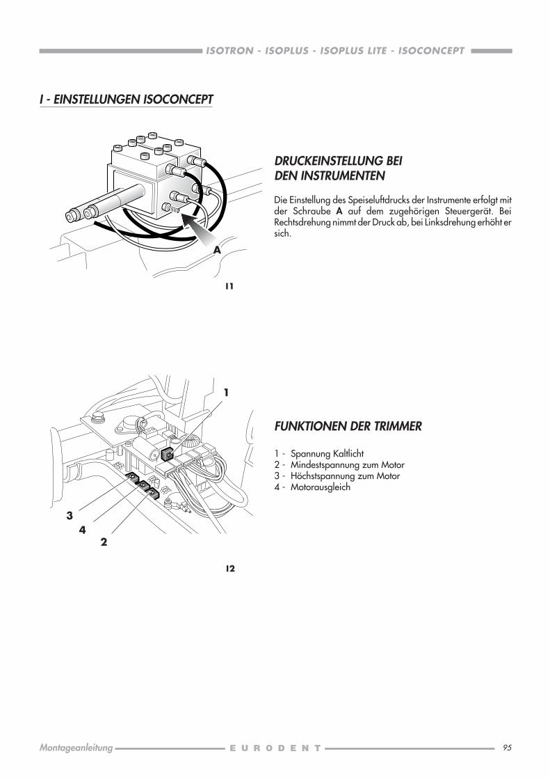
95
ISOTRON - ISOPLUS - ISOPLUS LITE - ISOCONCEPT
Montageanleitung
I2
FUNKTIONEN DER TRIMMER
1 - Spannung Kaltlicht2 - Mindestspannung zum Motor3 - Höchstspannung zum Motor4 - Motorausgleich
1
34
DRUCKEINSTELLUNG BEIDEN INSTRUMENTEN
Die Einstellung des Speiseluftdrucks der Instrumente erfolgt mitder Schraube A auf dem zugehörigen Steuergerät. BeiRechtsdrehung nimmt der Druck ab, bei Linksdrehung erhöht ersich.
I1
I - EINSTELLUNGEN ISOCONCEPT
A
2

97
ISOTRON - ISOPLUS - ISOPLUS LITE - ISOCONCEPT
Guía de instalación
CONDICIONES PRELIMINARES ................................................................................ 98DECLARACION DE RESPONSABILIDAD .................................................................... 98PREAJUSTE.............................................................................................................. 99
A EMBALAJE DE LOS SILLONES ISORAMA E ISO ...................................................100TRANSPORTE Y INSTALACION ......................................................................... 101
B INSTALACION DEL SILLON ISORAMA ................................................................ 102PREPARACION .................................................................................................102DESBLOQUEO DEL RESPALDO ..........................................................................102FIJACION DEL RESPALDO ................................................................................. 102PRUEBA DE FUNCIONAMIENTO ....................................................................... 103ALMOHADA RESPALDO ...................................................................................103ALMOHADA ASIENTO ..................................................................................... 104
C INSTALACION DEL SILLON ISO ......................................................................... 105RESPALDO ....................................................................................................... 105TAPICERIA RESPALDO ...................................................................................... 105TAPICERIA ASIENTO ........................................................................................106MONTAJE DE LOS BRAZOS ..............................................................................106
D APOYACABEZA PARA SILLONES ISORAMA E ISO .............................................. 108
E INSTALACION DE LOS EQUIPOS DENTALESISOTRON, ISOPLUS, ISOPLUS LITE, ISOCONCEPT ...............................................109
F CONEXIONES ELECTRICAS Y ELECTRONEUMATICAS .......................................... 114ISOTRON, ISOPLUS, ISOPLUS LITE .....................................................................114ISOCONCEPT ..................................................................................................116
G CONEXIONES DE LA BOMBA ASPIRANTE ..........................................................118
H PREAJUSTE LAMPARA ISOSUN PARA ISOTRON, ISOPLUS, ISOPLUS LITE .............118
I AJUSTES ISOCONCEPT .....................................................................................119AJUSTE DE LA PRESIÓN EN LOS INSTRUMENTOS ............................................. 119FUNCIONES DE LOS TRIMMER ......................................................................... 119
INDICE Página

98
ISOTRON - ISOPLUS - ISOPLUS LITE - ISOCONCEPT
Guía de instalación
CONDICIONES PRELIMINARES
El equipo a instalar ha sido catalogado de CLASE I,con piezas aplicadas de TIPO B ,
con bisturí electrónico o electrobisturí con pieza aplicada de TIPO BF (Sólo ISOTRON, ISOPLUS, ISOPLUS LITE).
Términos de clasificación (EN60 601-1):5.3 Aparatos comunes (aparatos con involucro no protegido contra la penetración de agua);5.5 Aparatos para no utilizarse en presencia de una mezcla anestésica inflamable con aire o con oxígeno o con óxido
nitroso;5.6 Aparatos para funcionamiento continuo con carga intermitente.
Funcionamiento: 220 V / 50 Hz / 1350 VA (sólo equipo 550 VA) para ISOTRON, ISOPLUS, ISOPLUS LITE.220 V / 50 Hz / 1000 VA (sólo equipo 200 VA) para ISOCONCEPT.
Método operante: continuo, de carga intermitente.Máx. capacidad de levantamiento: 120 Kg (equipo dental y lámpara excluidos).
El piso debe corresponder a las normas DIN 1055 B1.3 y DIN 18560 T1.
Se pide la instalación de un interruptor principal exterior de pared bipolar conforme a las normas y con las siguientescaracterísticas eléctricas: 250 V/10 A, para desconectar el equipo de la alimentación principal en caso de intervención oinspección dentro ésto.
La instalación eléctrica debe corresponder a las normas IEC 64.4, y ser realizada con conductores de protección de diferencial(con índice < 30 mA) de 16A/250V.En particular, la puesta a tierra debe conformarse al art. 3.2.01 de las normas arriba mencionadas.
La presión del agua de entrada del equipo tiene que encontrarse entre 1.8 y 3.0 bar. El conducto del agua tiene que suministrarpor lo menos 5 lt/minuto.Las características del agua deben corresponder a los requerimientos de las normas DIN 1988 y el grado de dureza debeser ≤ 8° dH (correspondientes a 1.432 mmol/l.).Se recomienda instalar en la salida del tubo de agua (preferiblemente de Ø 15 mm.) una válvula reductora de presión congrifo.
La presión de aire suministrada por el compresor tiene que encontrarse entre 5.0 y 7.0 bar. Utilizar un compresor de seco,con emisión de aire de 60 l./min. a 5 bar. Se recomienda instalar un grifo en la salida del tubo (preferiblemente de Ø 15 mm.).
El diámetro interior del tubo de desagüe tiene que ser 40 mm., reducidos a 32 mm. en la embocadura; su gradiente dedescenso tiene que ser mínimo 1 cm./m., y los ángulos de los codos no deben ser inferiores a 135°.
El diámetro interior del tubo de aspiración tiene que ser aproximadamente 32/40 mm. Se recomienda ver las instruccionesproporcionadas por el productor de la bomba aspirante.
Todos los preajustes tienen que ser realizados según las indicaciones de la pagina siguiente adjuntadas a cada equipo dentaly después de haber consultado el plan de instalación en escala 1:1 (código 633580010).
La EURODENT ruega las personas interesadas que consulten el catálogo Lista piezas de repuesto y se empeña a proveer otrainformación sobre lo que no aparezca en éste.
La EURODENT asume la responsabilidad de la seguridad y de la fiabilidad del aparato sólo si:• las operaciones de instalación, ensamblaje, extensiones, regulaciones, reparaciones han sido efectuadas por personas
autorizadas;• la instalación general y eléctrica del lugar correspondiente es conforme a las prescripciones relativas;• el aparato ha sido instalado en conformidad a la “GUÍA DE INSTALACIÓN”;• el aparato es empleado en conformidad a la “GUÍA DE MANEJO”.
0051 Los aparatos son conformes a los requisitos esenciales de la Directiva CE 93/42.
Tierra de protección
Cuidado, véase la documentación anexa

99
ISOTRON - ISOPLUS - ISOPLUS LITE - ISOCONCEPT
Guía de instalación
PREAJUSTE
..
.....
5060
175
E
A
A 3/8"G
20
B
C D
35
295
150
80
40
40 30
40
B
C
3/8"G
20
25
ø 32ø
40
D
E
25
500
ø 32
ø 4
0
ISOSUN
A. Agua: 3/8" G
B. Aire: 3/8" G
C. Desagüe: Ø 32
D. Aspiración: Ø 32
Activación bomba: 2 x 1 mm2
E. Timbre: 2 x 0,5 mm2
Red: 3 x 2,5 mm2
Agujero defijación en el piso
Agujero defijación en el piso

100
ISOTRON - ISOPLUS - ISOPLUS LITE - ISOCONCEPT
Guía de instalación
A0
1
ALTO
BOLOGNA
ITALYCOD OPZIONEMATR.
Kg. netos ...... 131Kg. brutos .... 152m3 ................ 0,6cm. 125 x 69 x 70
2
ALTO
BOLOGNA
ITALYCOLORE OOPZIONE
TAPPEZZERIA
CODICEMATR.
A - EMBALAJE DE LOS SILLONES ISORAMA E ISO
Para estos sillones ha sido estudiada una solución particular de embalaje que reduce al mínimo su volumen.
Por esto, el cuerpo del sillón se encuentra en el interior del embalaje 1 con el respaldo reclinado sobre el asiento (véase lafigura A0). La tapicería se encuentra en el embalaje 2 , que además contiene el asiento, el respaldo y el apoyacabeza.
Para quitar el sillón de su embalaje, cortar la caja 1 a lo largo de la línea punteada.
ISORAMAKg. netos ...... 116Kg. brutos .... 137m3 ................ 0,6cm. 125 x 69 x 70
ISO
Kg. netos ........ 13Kg. brutos ...... 18m3 ................ 0,2cm. 115 x 65 x 25
ISORAMAKg. netos....... 10Kg. brutos ..... 16m3 ............. 0,12cm. 93 x 51 x 25
ISO
ISORAMA
ISO

101
ISOTRON - ISOPLUS - ISOPLUS LITE - ISOCONCEPT
Guía de instalación
A1
CUIDADO: Cuando NO sea posible efectuar la conexióndentro de la base, introducir los tubos y los cables eléctricos enla parte delantera sacando, por medio de un cuchillo, los dostapones cerrados con un diafragma.
A2
B
AA
B
TRANSPORTE Y INSTALACION
Después de haber levantado el sillón del embalaje y, antes de trasladarlo, quitar el cárter de cobertura de la caja de conexión,lo que facilitará la toma del sillón y el transporte. No levantar el sillón sosteniéndolo por la cabeza del pantógrafo o por elapoyapiernas. Posicionar el sillón de manera que todos los empalmes (de aire, agua, desagüe y las tomas eléctricas) seencuentren en la caja de conexión (ubicada en la base del paralelogramo del sillón). Atención: al deslizarse el sillón sobreel piso poner cuidado en los cables eléctricos a fin de que no se aplasten ni se desgarren; tener cuidado especialmente enel cable del pedal.Asegurarse que el nivel del piso sea regular en la zona de apoyo de la base. Fijar el sillón por medio de adecuados tornillosde expansión (tipo Fischer) en dotación, en los dos puntos indicados en el dibujo (fig. A1).Los bulones son de rosca métrica M6 y de su llave. La profundidad del agujero en el piso debe ser por lo menos 115 mm.Para el montaje, se aconseja conectar momentáneamente el sillón a la corriente de manera que se pueda levantarlo porel pedal.CUIDADO! No se permite accionar los movimientos del respaldo antes de conectarlo al motor y al dispositivo delTrendelenburg.Al alcanzar la altura del sillón cómoda para trabajar, cortar la corriente.
Bulón M6 x 140
Tuerca de empotramiento
Distanciador largo
Bulón M6 x 110
Distanciador corto
Tuerca deempotramiento
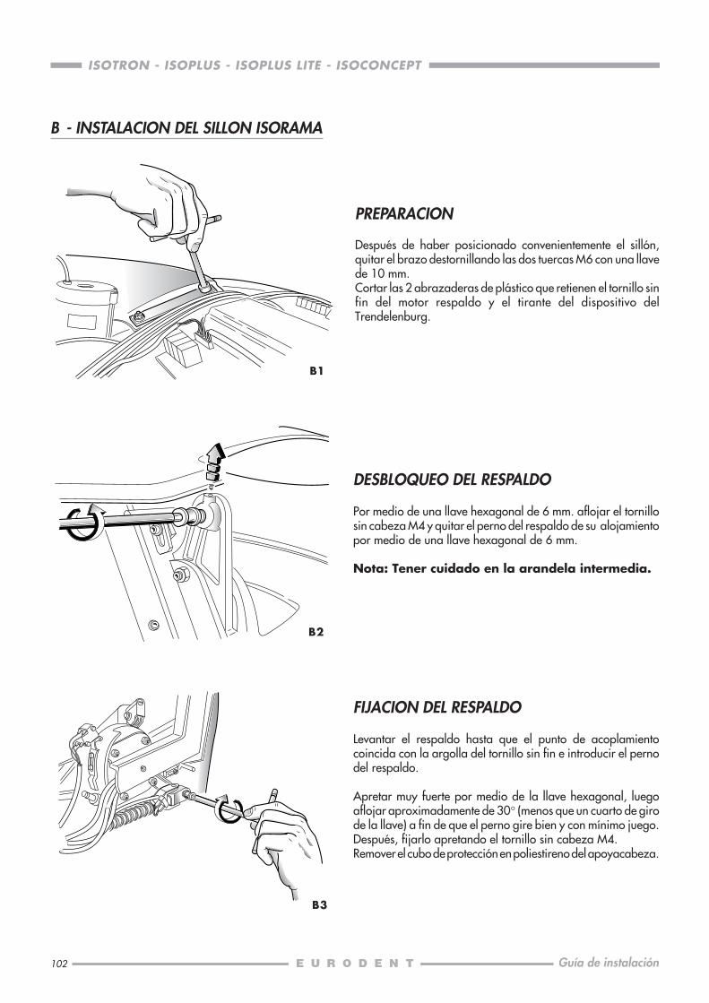
102
ISOTRON - ISOPLUS - ISOPLUS LITE - ISOCONCEPT
Guía de instalación
PREPARACION
Después de haber posicionado convenientemente el sillón,quitar el brazo destornillando las dos tuercas M6 con una llavede 10 mm.Cortar las 2 abrazaderas de plástico que retienen el tornillo sinfin del motor respaldo y el tirante del dispositivo delTrendelenburg.
B1
B2
B3
B - INSTALACION DEL SILLON ISORAMA
DESBLOQUEO DEL RESPALDO
Por medio de una llave hexagonal de 6 mm. aflojar el tornillosin cabeza M4 y quitar el perno del respaldo de su alojamientopor medio de una llave hexagonal de 6 mm.
Nota: Tener cuidado en la arandela intermedia.
FIJACION DEL RESPALDO
Levantar el respaldo hasta que el punto de acoplamientocoincida con la argolla del tornillo sin fin e introducir el pernodel respaldo.
Apretar muy fuerte por medio de la llave hexagonal, luegoaflojar aproximadamente de 30° (menos que un cuarto de girode la llave) a fin de que el perno gire bien y con mínimo juego.Después, fijarlo apretando el tornillo sin cabeza M4.Remover el cubo de protección en poliestireno del apoyacabeza.
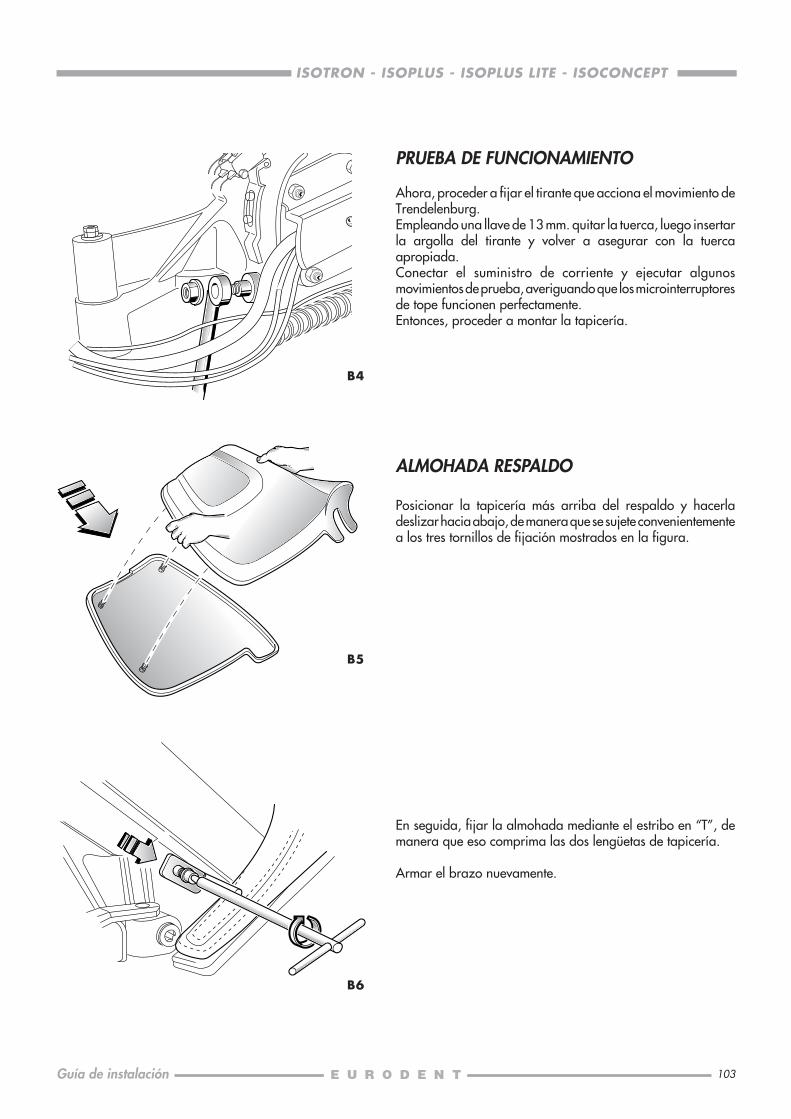
103
ISOTRON - ISOPLUS - ISOPLUS LITE - ISOCONCEPT
Guía de instalación
B4
B6
B5
PRUEBA DE FUNCIONAMIENTO
Ahora, proceder a fijar el tirante que acciona el movimiento deTrendelenburg.Empleando una llave de 13 mm. quitar la tuerca, luego insertarla argolla del tirante y volver a asegurar con la tuercaapropiada.Conectar el suministro de corriente y ejecutar algunosmovimientos de prueba, averiguando que los microinterruptoresde tope funcionen perfectamente.Entonces, proceder a montar la tapicería.
ALMOHADA RESPALDO
Posicionar la tapicería más arriba del respaldo y hacerladeslizar hacia abajo, de manera que se sujete convenientementea los tres tornillos de fijación mostrados en la figura.
En seguida, fijar la almohada mediante el estribo en “T”, demanera que eso comprima las dos lengüetas de tapicería.
Armar el brazo nuevamente.

104
ISOTRON - ISOPLUS - ISOPLUS LITE - ISOCONCEPT
Guía de instalación
B8
B10
B7
B9
ALMOHADA ASIENTO
Conectar el cable de tierra como mostrado en la figura.
Si no se encuentran ya instalados, poner los tornillos sin cabezaen su encaje (él largo en el agujero posterior izquierdo) yfijarlos por medio de las contratuercas.Poner los tornillos delanteros también.
Luego, según muestra la figura, posicionar la tapicería teniendocuidado en insertar bien los tornillos sin cabeza en los apropiadosagujeros.
Ahora, asegurar la almohada atornillando las tuercas cilíndricaslargas apropiadas en los tornillos sin cabeza.Para efectuar esta operación, utilizar la llave larga en dotación.
Para fijar la parte delantera, utilizar los tornillos M4 x 40.

105
ISOTRON - ISOPLUS - ISOPLUS LITE - ISOCONCEPT
Guía de instalación
C - INSTALACION DEL SILLON ISO
C2
C3
C1
RESPALDO
Cortar la caja a lo largo de la línea delineada y quitar el sillóndel embalaje. Levantar el respaldo hasta que coincida el puntode fijación y, cuidadosamente, introducir el pivote respaldo.A este punto introducir el tornillo y apretar muy fuerte con lallave.
El sillón puede ahora ser puesto en función. Háganse algunosmovimientos de prueba y asegurarse de que los micros dellimitador de carrera funcionen perfectamente.
La operación sucesiva es el montaje del tapizado.
TAPICERIA RESPALDO
Posicionar la tapicería más arriba del respaldo y hacerladeslizar hacia abajo, de manera que se sujete convenientementea los dos tornillos de fijación.
Cuando ésta es bien posicionada introducir el tornillo en elfondo de la parte tapizada en el agujero apropiado obtenidoen el revés. Tener presionado y apretar la clavija M4 con lallave de anillo hexagonal de mm 2.
Si el acoplamiento de la almohada con el respaldo no fuesecorrecto, actuar sobre los dos tornillos de cabeza avellanadacomo indicado para la almohada del apoyacabeza.

106
ISOTRON - ISOPLUS - ISOPLUS LITE - ISOCONCEPT
Guía de instalación
C4
MONTAJE DE LOS BRAZOS
Primera operación: introducir la clavija perfilada Ø 8 en elalojamiento del respaldo con la parte del brazo a 90° respectoal respaldo es decir con el fresado sobre la punta del pivoteparalelo al perfil anterior del respaldo mismo.
C5
Rodando el brazo, el pivote queda introducido, pues efectuarla fijación de la parte inferior del mismo.
C6
TAPICERIA ASIENTO
Se posiciona la almohada sobre el asiento y se fija con los trestornillos M4, que salen por debajo, apretando bien las tuercasde manera que se forme un cuerpo único.

107
ISOTRON - ISOPLUS - ISOPLUS LITE - ISOCONCEPT
Guía de instalación
Por lo que atañe el brazo izquierdo la sujeción se obtiene consu perno, mientras que el derecho se introduce en el carrodeslizadero.
C7
El brazo derecho es deslizadero, para desbloquearlo del puntofijo es suficiente tirar hacia arriba la parte anterior.
C8
C9
C10
Deslizar el brazo hacia la parte anterior del sillón, llevándoloa fin de carrera sobre el carro de deslizamiento.
Dicho brazo se pone también en ángulo negativo y puede,también en esta posición, seguir los movimientos del respaldo.
Se quita con facilidad llevando a la justa posición la lengüetamóvil que completa el pivote extraíble, después se actúaextrayendo el pivote del respaldo siguiendo el orden contrariode la descripción en objeto.

108
ISOTRON - ISOPLUS - ISOPLUS LITE - ISOCONCEPT
Guía de instalación
D2
D - APOYACABEZA PARA SILLONES ISORAMA E ISO
D1
El montaje es muy simple y claro:
es suficiente colocarlo, luego, después de introducir las doscabezas de los tornillos en sus alojamientos y, empujandohacia abajo, introducir los dos pasadores en los respectivosagujeros. Después, por medio de una llave hexagonal de 2mm. apretar los tornillos de sujeción sin cabeza, teniendounidos y presionando el apoyacabeza y la almohada.
Para tener un correcto acoplamiento de la almohada con elrespaldo, es necesario actuar sobre los dos tornillos decabeza avellanada que fijan la almohada.Después de haber aflojado las contratuercas, se bajan olevantan los tornillos arriba mencionados de la cantidadnecesaria para el acoplamiento apropiado.Después cierrese nuevamente las dos tuercas.
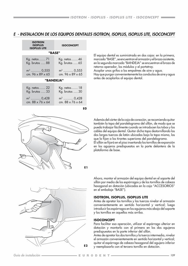
109
ISOTRON - ISOPLUS - ISOPLUS LITE - ISOCONCEPT
Guía de instalación
E0
E1
E2
Ahora, montar el armazón del equipo dental en el soporte delsillón por medio de los espárragos y de los tornillos de cabezahexagonal en dotación (ubicados en la caja “ACCESORIOS”en el embalaje “BASE”).
ISOTRON, ISOPLUS, ISOPLUS LITEAntes de apretar los tornillos y las tuercas nivelar el armazónconvenientemente en sentido horizontal y vertical; luegointroducir los espárragos en los agujeros más abajo del soportey los tornillos en aquellos más arriba.
ISOCONCEPTPara facilitar esa operación, utilizar el espárrago ulterior endotación y montarlo con el primero en los dos agujerospredispuestos en la parte inferior del sillón.Antes de apretar los dos tornillos y la tuerca intermedia, nivelarel armazón convenientemente en sentido horizontal y vertical;quitar el espárrago de cabeza hexagonal del agujero inferiory reemplazarlo con el tercero tornillo en dotación.
m3 ........... 0,555cm. 96 x 89 x 65
Kg. netos....... 22Kg. brutos ..... 33
m3 ...........0,428cm. 88 x 76 x 64
E - INSTALACION DE LOS EQUIPOS DENTALES ISOTRON, ISOPLUS, ISOPLUS LITE, ISOCONCEPT
Kg. netos ....... 71Kg. brutos ..... 88
m3 ........... 0,555cm. 96 x 89 x 65
ISOTRONISOPLUS
ISOPLUS LITEISOCONCEPT
m3 ...........0,428cm. 88 x 76 x 64
"BASE"
"BANDEJA"
Kg. netos .......46Kg. brutos ..... 65
Kg. netos....... 18Kg. brutos ..... 30
Además del cárter de la caja de conexión, se recomienda quitartambién la tapa del paralelogramo del sillón, de modo que sepueda trabajar fácilmente cuando se introducen los tubos y loscables del equipo dental. Quitar dicha tapa destornillando lasdos largas tuercas de latón ubicadas bajo la tapa misma, lasque la fijan a los tirantes superiores del paralelogramo.El sillón se fijará en el piso insertando los tornillos de expansiónen los agujeros predispuestos en la parte delantera de laplataforma de base.
El equipo dental es suministrado en dos cajas: en la primera,marcada “BASE”, se encuentran el armazón y el brazo asistente,en la segunda marcada “BANDEJA” se encuentran el brazo deretorno operador, los módulos y el portatray.Acoplar unos grifos a los empalmes de aire y agua.Hay que purgar convenientemente los conductos de aire y aguaantes de acoplarlos al equipo dental.
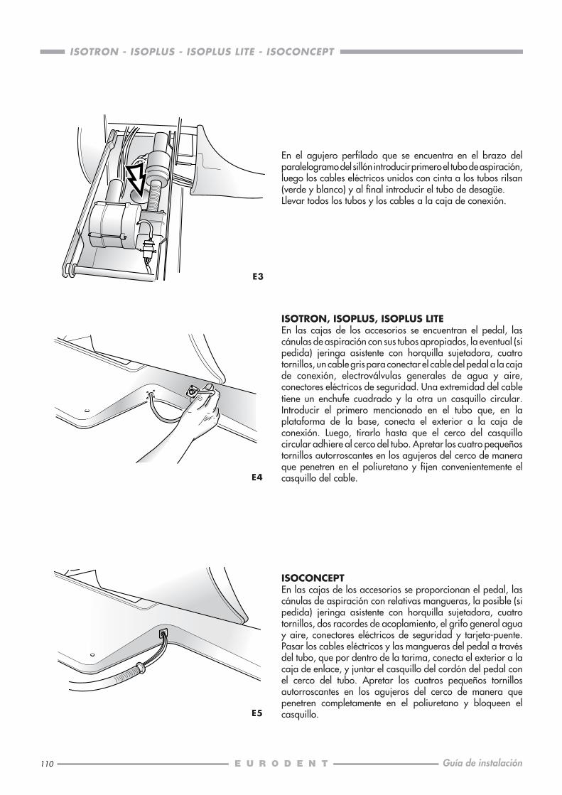
110
ISOTRON - ISOPLUS - ISOPLUS LITE - ISOCONCEPT
Guía de instalación
E3
En el agujero perfilado que se encuentra en el brazo delparalelogramo del sillón introducir primero el tubo de aspiración,luego los cables eléctricos unidos con cinta a los tubos rilsan(verde y blanco) y al final introducir el tubo de desagüe.Llevar todos los tubos y los cables a la caja de conexión.
ISOTRON, ISOPLUS, ISOPLUS LITEEn las cajas de los accesorios se encuentran el pedal, lascánulas de aspiración con sus tubos apropiados, la eventual (sipedida) jeringa asistente con horquilla sujetadora, cuatrotornillos, un cable gris para conectar el cable del pedal a la cajade conexión, electroválvulas generales de agua y aire,conectores eléctricos de seguridad. Una extremidad del cabletiene un enchufe cuadrado y la otra un casquillo circular.Introducir el primero mencionado en el tubo que, en laplataforma de la base, conecta el exterior a la caja deconexión. Luego, tirarlo hasta que el cerco del casquillocircular adhiere al cerco del tubo. Apretar los cuatro pequeñostornillos autorroscantes en los agujeros del cerco de maneraque penetren en el poliuretano y fijen convenientemente elcasquillo del cable.E4
ISOCONCEPTEn las cajas de los accesorios se proporcionan el pedal, lascánulas de aspiración con relativas mangueras, la posible (sipedida) jeringa asistente con horquilla sujetadora, cuatrotornillos, dos racordes de acoplamiento, el grifo general aguay aire, conectores eléctricos de seguridad y tarjeta-puente.Pasar los cables eléctricos y las mangueras del pedal a travésdel tubo, que por dentro de la tarima, conecta el exterior a lacaja de enlace, y juntar el casquillo del cordón del pedal conel cerco del tubo. Apretar los cuatros pequeños tornillosautorroscantes en los agujeros del cerco de manera quepenetren completamente en el poliuretano y bloqueen elcasquillo.E5

111
ISOTRON - ISOPLUS - ISOPLUS LITE - ISOCONCEPT
Guía de instalación
Ahora, instalar el brazo bandeja del equipo dental (primerointroducir el cable y los tubos en el armazón) y bloquear lacarrera del brazo insertando el tornillo y la tuerca (en dotacióncon los accesorios) en el agujero del perno.
ISOTRON, ISOPLUS, ISOPLUS LITEEnchufar el cable del brazo en la toma CN1 (arriba, a laizquierda), en la tarjeta de baja tensión.Luego, conectar el tubo blanco a la unión rápida para el airea los módulos, ubicada a la derecha del grupo reductor de aire.Ahora, conectar el tubo rojo (sólo ISOTRON) a la uniónubicada en la tapa del colector de amalgama, y el tubo verdeal grupo de distribución del agua (para vaso, jeringa asistentey módulos), ubicado al lado del sillón.
ISOCONCEPTEnchufar el cable del brazo en las tomas X1 y X2 (arriba, a laizquierda), en la tarjeta.Luego, conectar la manguera blanca 3/5 al enchufe rápidopara el aire permanente, ubicada a la derecha del gruporeductor de aire. Conectar la manguerilla verde al grupo dedistribución del agua.Los restantes tubos van conectados a los respectivos empalmespasadores situados en el grupo hídrico.
NOTA: Durante el montaje respetar siempre lascorrespondencias de los colores de los tubos.
E6
E7
E8
Fijar la bandeja “portatray” debajo de la tabla portamódulos(para facilitar el trabajo, utilizar una llave de 17 tubular o detubo).
Introducir el cable y el perno del brazo asistente en el alojamientoadecuado (en el fondo del armazón, al lado del sillón), yasegurar el perno con el anillo elástico Seeger y su arandelaespaciadora de refuerzo.Hacer pasar el cable en el armazón hasta que se enchufe en latoma C5 (para ISOTRON) o C2 (para ISOPLUS e ISOPLUS LITE)que se encuentra en la tarjeta de baja tensión, o, en el caso delmodelo ISOCONCEPT, en la toma X5 de la tarjeta del armazón(asegurarse que el cable no quede pendiente bajo el armazón).Introducir el grupo de fricción en el agujero cerca de elalojamiento del perno y apretar el tornillo convenientemente.
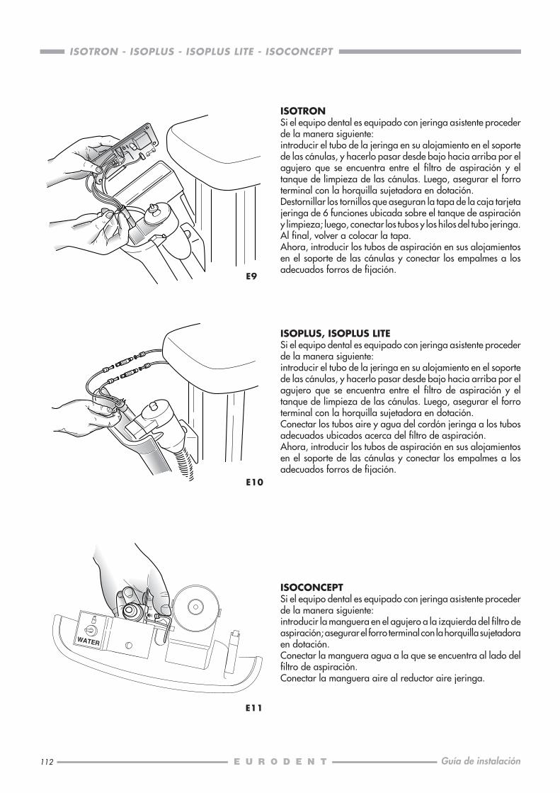
112
ISOTRON - ISOPLUS - ISOPLUS LITE - ISOCONCEPT
Guía de instalación
E9
ISOTRONSi el equipo dental es equipado con jeringa asistente procederde la manera siguiente:introducir el tubo de la jeringa en su alojamiento en el soportede las cánulas, y hacerlo pasar desde bajo hacia arriba por elagujero que se encuentra entre el filtro de aspiración y eltanque de limpieza de las cánulas. Luego, asegurar el forroterminal con la horquilla sujetadora en dotación.Destornillar los tornillos que aseguran la tapa de la caja tarjetajeringa de 6 funciones ubicada sobre el tanque de aspiracióny limpieza; luego, conectar los tubos y los hilos del tubo jeringa.Al final, volver a colocar la tapa.Ahora, introducir los tubos de aspiración en sus alojamientosen el soporte de las cánulas y conectar los empalmes a losadecuados forros de fijación.
E10
ISOPLUS, ISOPLUS LITESi el equipo dental es equipado con jeringa asistente procederde la manera siguiente:introducir el tubo de la jeringa en su alojamiento en el soportede las cánulas, y hacerlo pasar desde bajo hacia arriba por elagujero que se encuentra entre el filtro de aspiración y eltanque de limpieza de las cánulas. Luego, asegurar el forroterminal con la horquilla sujetadora en dotación.Conectar los tubos aire y agua del cordón jeringa a los tubosadecuados ubicados acerca del filtro de aspiración.Ahora, introducir los tubos de aspiración en sus alojamientosen el soporte de las cánulas y conectar los empalmes a losadecuados forros de fijación.
E11
ISOCONCEPTSi el equipo dental es equipado con jeringa asistente procederde la manera siguiente:introducir la manguera en el agujero a la izquierda del filtro deaspiración; asegurar el forro terminal con la horquilla sujetadoraen dotación.Conectar la manguera agua a la que se encuentra al lado delfiltro de aspiración.Conectar la manguera aire al reductor aire jeringa.

113
ISOTRON - ISOPLUS - ISOPLUS LITE - ISOCONCEPT
Guía de instalación
E12
E13
En la caja de conexión: fijar el grupo de las electroválvulas deaire y agua en el lado izquierdo, empleando los dos tornillosen dotación.Tener cuidado en la dirección del flujo de las válvulas (indicadapor una flecha en el cuerpo de latón) cuando se conectan lostubos de aire y agua. El grupo conectores eléctricos deberá serasegurado al lado derecho de la caja, por medio de los tornilloscon sus tuercas en dotación.
Introducir el poste de soporte de la lámpara en su alojamientoy asegurarlo atornillando los dos tornillos ya posicionados enla lámpara (lado interior del armazón). Hacer pasar unacadena piloto en el soporte y fijarla con cinta adhesiva al cableque sale del perno del brazo de la lámpara. Tirar la cadenapiloto e introducir el perno en el poste, luego conectar el cablede la lámpara a los bornes 3-4 de la toma M4 que se encuentraen la tarjeta AT/BT (lado sillón).(En el caso de ISOCONCEPT el borne es el XT1 de la tarjetaarmazón).
E14
Alojar la escupidera.
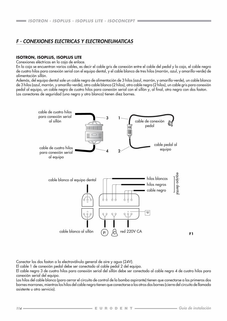
114
ISOTRON - ISOPLUS - ISOPLUS LITE - ISOCONCEPT
Guía de instalación
F - CONEXIONES ELECTRICAS Y ELECTRONEUMATICAS
ISOTRON, ISOPLUS, ISOPLUS LITEConexiones eléctricas en la caja de enlace.En la caja se encuentran varios cables, es decir el cable gris de conexión entre el cable del pedal y la caja, el cable negrode cuatro hilos para conexión serial con el equipo dental, y el cable blanco de tres hilos (marrón, azul, y amarillo-verde) dealimentación sillón.Además, del equipo dental sale un cable negro de alimentación de 3 hilos (azul, marrón, y amarillo-verde), un cable blancode 3 hilos (azul, marrón, y amarillo-verde), otro cable blanco (2 hilos), otro cable negro (2 hilos), un cable gris para conexiónpedal al equipo, un cable negro de cuatro hilos para conexión serial con el sillón y, al final, otro negro con dos faston.Los conectores de seguridad (uno negro y otro blanco) tienen diez bornes.
Conectar los dos faston a la electroválvula general de aire y agua (24V).El cable 1 de conexión pedal debe ser conectado al cable pedal 2 del equipo.El cable negro 3 de cuatro hilos para conexión serial del sillón debe ser conectado al cable negro 4 de cuatro hilos paraconexión serial del equipo.Los hilos del cable blanco (para cerrar el circuito de control de la bomba aspirante) tienen que conectarse a los primeros dosbornes marrones, mientras los hilos del cable negro tienen que conectarse a los otros dos bornes (cierre del circuito de llamadaasistente u otro servicio).
P. C F1
3
4
1
2
cable de cuatro hilospara conexión serial
al sillón
hilos negroshilos blancos
cable negro
cable blanco al equipo dental
cable blanco al sillón red 220V CA
equipo dental
cable de cuatro hilospara conexión serial
al equipo
cable de conexiónpedal
cable pedal alequipo
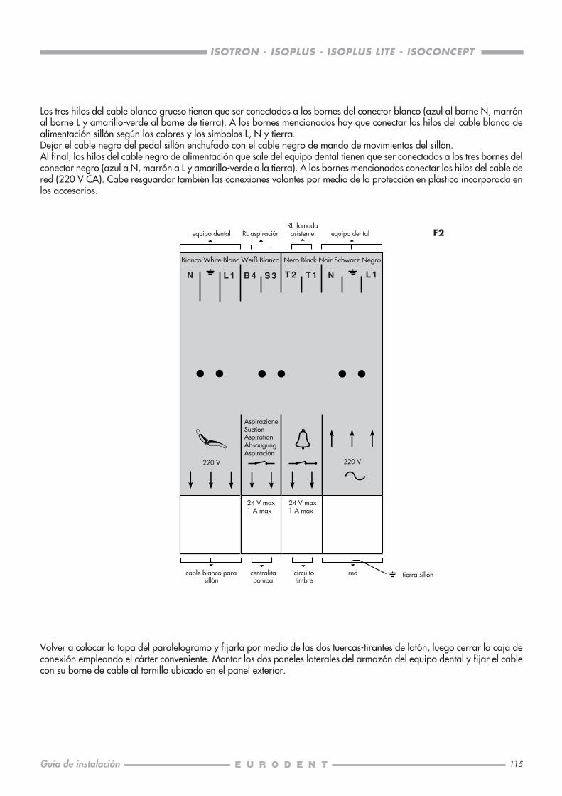
115
ISOTRON - ISOPLUS - ISOPLUS LITE - ISOCONCEPT
Guía de instalación
220 V 220 V
N L 1 B 4 S 3 T 2 T 1 N L 1
F2
Bianco White Blanc Weiß Blanco Nero Black Noir Schwarz Negro
AspirazioneSuctionAspirationAbsaugungAspiración
24 V max1 A max
24 V max1 A max
Los tres hilos del cable blanco grueso tienen que ser conectados a los bornes del conector blanco (azul al borne N, marrónal borne L y amarillo-verde al borne de tierra). A los bornes mencionados hay que conectar los hilos del cable blanco dealimentación sillón según los colores y los símbolos L, N y tierra.Dejar el cable negro del pedal sillón enchufado con el cable negro de mando de movimientos del sillón.Al final, los hilos del cable negro de alimentación que sale del equipo dental tienen que ser conectados a los tres bornes delconector negro (azul a N, marrón a L y amarillo-verde a la tierra). A los bornes mencionados conectar los hilos del cable dered (220 V CA). Cabe resguardar también las conexiones volantes por medio de la protección en plástico incorporada enlos accesorios.
Volver a colocar la tapa del paralelogramo y fijarla por medio de las dos tuercas-tirantes de latón, luego cerrar la caja deconexión empleando el cárter conveniente. Montar los dos paneles laterales del armazón del equipo dental y fijar el cablecon su borne de cable al tornillo ubicado en el panel exterior.
equipo dentalRL llamadaasistente equipo dentalRL aspiración
cable blanco parasillón
centralitabomba
circuitotimbre
red tierra sillón
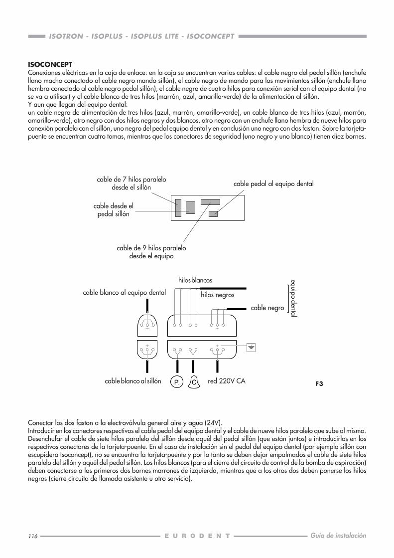
116
ISOTRON - ISOPLUS - ISOPLUS LITE - ISOCONCEPT
Guía de instalación
ISOCONCEPTConexiones eléctricas en la caja de enlace: en la caja se encuentran varios cables: el cable negro del pedal sillón (enchufellano macho conectado al cable negro mando sillón), el cable negro de mando para los movimientos sillón (enchufe llanohembra conectado al cable negro pedal sillón), el cable negro de cuatro hilos para conexión serial con el equipo dental (nose va a utilisar) y el cable blanco de tres hilos (marrón, azul, amarillo-verde) de la alimentación al sillón.Y aun que llegan del equipo dental:un cable negro de alimentación de tres hilos (azul, marrón, amarillo-verde), un cable blanco de tres hilos (azul, marrón,amarillo-verde), otro negro con dos hilos negros y dos blancos, otro negro con un enchufe llano hembra de nueve hilos paraconexión paralela con el sillón, uno negro del pedal equipo dental y en conclusión uno negro con dos faston. Sobre la tarjeta-puente se encuentran cuatro tomas, mientras que los conectores de seguridad (uno negro y uno blanco) tienen diez bornes.
F3P. C
Conectar los dos faston a la electroválvula general aire y agua (24V).Introducir en los conectores respectivos el cable pedal del equipo dental y el cable de nueve hilos paralelo que sube al mismo.Desenchufar el cable de siete hilos paralelo del sillón desde aquél del pedal sillón (que están juntos) e introducirlos en losrespectivos conectores de la tarjeta-puente. En el caso de instalación sin el pedal del equipo dental (por ejemplo sillón conescupidera Isoconcept), no se encuentra la tarjeta-puente y por lo tanto se deben dejar empalmados el cable de siete hilosparalelo del sillón y aquél del pedal sillón. Los hilos blancos (para el cierre del circuito de control de la bomba de aspiración)deben conectarse a los primeros dos bornes marrones de izquierda, mientras que a los otros dos deben ponerse los hilosnegros (cierre circuito de llamada asistente u otro servicio).
hilos blancos
cable negro
cable blanco al sillón red 220V CA
equipo dental
cable pedal al equipo dental
cable blanco al equipo dental
cable de 7 hilos paralelodesde el sillón
cable desde elpedal sillón
cable de 9 hilos paralelodesde el equipo
hilos negros

117
ISOTRON - ISOPLUS - ISOPLUS LITE - ISOCONCEPT
Guía de instalación
F4
F5
220 V 220 V
N L 1 B 4 S 3 T 2 T 1 N L 1
Bianco White Blanc Weiß Blanco Nero Black Noir Schwarz Negro
AspirazioneSuctionAspirationAbsaugungAspiración
24 V max1 A max
24 V max1 A max
Los tres hilos del cable blanco grueso tienen que ser conectados a los bornes del conector blanco (azul al borne N, marrónal borne L y amarillo-verde al borne de tierra). A los bornes mencionados hay que conectar los hilos del cable blanco dealimentación sillón según los colores y los símbolos L, N y tierra.Dejar el cable negro del pedal sillón enchufado con el cable negro de mando de movimientos del sillón.Al final, los hilos del cable negro de alimentación que sale del equipo dental tienen que ser conectados a los tres bornes delconector negro (azul a N, marrón a L y amarillo-verde a la tierra). A los bornes mencionados conectar los hilos del cable dered (220 V CA). Cabe resguardar también las conexiones volantes por medio de la protección en plástico incorporada enlos accesorios.
equipo dentalRL llamadaasistente equipo dentalRL aspiración
cable blanco parasillón
centralitabomba
circuitotimbre
red tierra sillón
Conectar las mangueras del pedal con lás de mismo color quesuben al equipo, por medio de los racordes proporcionados.Volver a colocar la tapa del paralelogramo y fijarla por mediode las dos tuercas-tirantes de latón, luego cerrar la caja deconexión empleando el cárter conveniente. Montar los dospaneles laterales del armazón del equipo dental y fijar el cablecon su borne de cable al tornillo ubicado en el panel exterior.
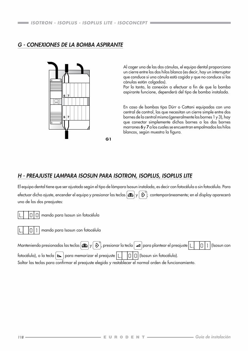
118
ISOTRON - ISOPLUS - ISOPLUS LITE - ISOCONCEPT
Guía de instalación
6 7
6 7
G - CONEXIONES DE LA BOMBA ASPIRANTE
H - PREAJUSTE LAMPARA ISOSUN PARA ISOTRON, ISOPLUS, ISOPLUS LITE
El equipo dental tiene que ser ajustado según el tipo de lámpara Isosun instalada, es decir con fotocélula o sin fotocélula. Para
efectuar dicho ajuste, encender el equipo y presionar las teclas y ; contemporáneamente; en el display aparecerá
uno de los dos preajustes:
mando para Isosun sin fotocélula
mando para Isosun con fotocélula
Manteniendo presionadas las teclas y , presionar la tecla para plantear el preajuste (Isosun con
fotocélula), o la tecla para memorizar el preajuste (Isosun sin fotocélula).
Soltar las teclas para confirmar el preajuste elegido y restablecer el normal orden de funcionamiento.
G1
Al coger una de las dos cánulas, el equipo dental proporcionaun cierre entre los dos hilos blanco (es decir, hay un interruptorque conduce si una cánula está cogida y que no conduce si lascánulas están colgadas).Por lo tanto, la conexión a efectuar a fin de que la bombaaspirante funcione, dependerá del tipo de bomba instalada.
En caso de bombas tipo Dürr o Cattani equipadas con unacentral de control, las que necesitan un cierre simple entre dosbornes de la central misma (generalmente los bornes 1 y 3), hayque conectar simplemente dichos bornes a los dos bornesmarrones 6 y 7 a los cuales se encuentran empalmados los hilosblancos, según muestra la figura.

119
ISOTRON - ISOPLUS - ISOPLUS LITE - ISOCONCEPT
Guía de instalación
I2
FUNCIONES DE LOS TRIMMER
1 - Tensión luz fría2 - Tensión mínima en el motor3 - Tensión máxima en el motor4 - Compensación del motor
1
34
AJUSTE DE LA PRESIÓN EN LOSINSTRUMENTOS
El ajuste de la presión del aire de alimentación de los instrumentosse efectúa por medio del tornillo A situado en la específicacentralita. Girando hacia la derecha la presión disminuye,hacia la izquierda aumenta.
I1
I - AJUSTES ISOCONCEPT
A
2


Realized by: STUDIO '80 grafica industriale Bologna
04/03 - COD. 653580041/B