ISC – Impatti sul Suolo e sulle Coste A s t r o o p e R · ISC – Impatti sul Suolo e sulle...
16
C C C E E E N N N T T T R R R O O O E E E U U U R R R O O O - - - M M M E E E D D D I I I T T T E E E R R R R R R A A A N N N E E E O O O P P P E E E R R R I I I C C C A A A M M B B B I I I A A A M M M E E E N N N T T T I I I C C C L L L I I I M M M A A A T T T I I I C C C I I I ISC – Impatti sul Suolo e sulle Coste A A M M R R A A : : L L a a b b o o r r a a t t o o r r y y e e q q u u i i p p m m e e n n t t Luciano Picarelli Analisi e Monitoraggio del Rischio Ambientale, AMRA Filippo Vinale Analisi e Monitoraggio del Rischio Ambientale, AMRA T T e e c c h h n n i i c c a a l l R R e e p p o o r r t t s s Centro Euro-Mediterraneo per i Cambiamenti Climatici www.cmcc.it Dicembre 2007 ■ TR14
Transcript of ISC – Impatti sul Suolo e sulle Coste A s t r o o p e R · ISC – Impatti sul Suolo e sulle...
CCCEEENNNTTTRRROOO EEEUUURRROOO---MMMEEEDDDIIITTTEEERRRRRRAAANNNEEEOOO PPPEEERRR III CCCAAAMMMBBBIIIAAAMMMEEENNNTTTIII CCCLLLIIIMMMAAATTTIIICCCIII
ISC – Impatti sul Suolo e sulle Coste
AAMMRRAA:: LLaabboorraattoorryy eeqquuiippmmeenntt
Luciano Picarelli Analisi e Monitoraggio del Rischio Ambientale, AMRA
Filippo Vinale Analisi e Monitoraggio del Rischio Ambientale, AMRA
TT eecc hh
nn iicc aa
ll RRee pp
oo rrtt ss
Centro Euro-Mediterraneo per i Cambiamenti Climatici www.cmcc.it
Dicembre 2007 ■ TR14

2
AMRA: Laboratory equipment
Summary Seepage analyses aimed to predict rainfall-induced slope failures can be calibrated through laboratory investigation, which provide hydraulic and mechanical parameters representative of soil behaviour. Thanks to laboratory equipment, A.M.R.A. will develop an experimental program to investigate the mechanisms of rainfall-induced landslides in some geomorphological contexts. The following report describes such instruments and the testing procedures.
Keywords: laboratory tests, flume, pressure plate
JEL Classification:
Address for correspondence: Luciano Picarelli A.M.R.A. S.c.a.r.l. Via Nuova Agnano, 11 80125 Napoli, Italy E-mail: [email protected] Filippo Vinale A.M.R.A. S.c.a.r.l. Via Nuova Agnano, 11 80125 Napoli, Italy E-mail: [email protected]

CONTENTS 1. Foreword…………………………………………………………………………………….4 2. Pressure plate………...…………………………………………………………………….4 3. Flume………………………………………………………………………………………...7
3.1 Soil preparation…………………………………………………………………………9 3.2 Monitoring system…………………………………………………………………….10
4. Procedures………………………………………………………………………………...14 5. Conclusions……..…………………………………………………………………………15 6. References………………………………………………………………………………...16

2
1. Foreword
Slope failures are caused by a combination of several factors, such as climatic conditions, geological features, topography and vegetation. In regions where the groundwater table is usually deep and soils are unsaturated, climatic conditions may significantly affect slope stability. In fact, while during dry periods the soil usually experiences high matric suction (i.e. negative pore-water pressure), which contributes to the shear strength of the soil, during prolonged wet periods matric suction decreases, causing a reduction of the shear strength and eventually inducing slope failure. This aspect is particularly pregnant in unsaturated pyroclastic deposits of Campania Region, where landslides are primarily provoked by rainfall. The main goal of the ongoing research is the individuation of a simple and rational procedure to link weather forecasting to prediction of slope failure. This procedure cannot leave out of the knowledge of the infiltration and/or the evaporation amounts and their contribution to the changes in suction, pore-water pressure and soil physical properties. That problem has inevitable repercussions on the choosing of soil representative parameters that have to be used as input data in numerical models. Laboratory investigation can furnish results that can be used to calibrate seepage analyses aimed to predict rainfall-induced slope failures. Therefore, A.M.R.A. will develop an experimental program, by using modern equipments to determine hydraulic and mechanical soil properties. In particular, thanks to pressure plates, tests to determine soil retention characteristics will be performed: these will provide information about the amount of water that can be stored by soil during meteoric events. Besides, the mechanisms of rainfall induced landslides in various geomorphological contexts will be investigated by an instrumented flume. The laboratory equipment and the testing procedures will be described in the following. 2. Pressure Plate
Hydraulic flow occurs only through soil voids. As during infiltration or evaporation processes the percentage of saturated voids continuously changes, soil permeability kw changes too: therefore, its value depends on the degree of saturation Sr (or on the
volumetric soil water content θw). As already explained in the Technical Report “Messa a punto di modelli geotecnici per la simulazione degli effetti al suolo delle precipitazioni”, the
degree of saturation Sr (or alternatively the water content θ w) is deeply linked to matric suction ua-uw through a strongly non-linear relationship called Soil Water Retention Curve (SWRC) (Fig. 1). Different studies aimed to investigate water flow through unsaturated soils reveale that field and laboratory methods to determine the unsaturated hydraulic conductivity are time consuming and present several difficulties. In order to overcome this problem, semi-empirical equations which derive hydraulic conductivity from the SWRC have been proposed. The SWRC essentially depends on grain size distribution and on porosity and can be obtained using different laboratory techniques: one of these is the translation-axis technique, which can be applied using pressure plates.

3
drying curvewetting curve
air entry value
residual air value
suction, ua-uw [kPa]
deg
ree
of
satu
rati
on
, S
r[%
]
drying curvewetting curve
air entry value
residual air value
suction, ua-uw [kPa]
deg
ree
of
satu
rati
on
, S
r[%
]
Figure 1. Soil Water Retention Curve
The pressure plate consists of an air-tight chamber enclosing a water saturated, high air-entry porous ceramic plate, whose underside is connected to a water saturated compartment, which is in turn linked to a pressure transducer (Fig. 2). Soil sample is placed on the top of the saturated ceramic plate, inside an air pressure chamber.
Figure 2. Scheme of the pressure changes associated with the measurement of matric suction using a pressure plate apparatus (from Fredlund and Rahardjo, 1993)

4
At the onset of the test, air pressure is equal to the atmospheric pressure (i.e. ua=0), thus the matric suction ua-uw is numerically equal to the positive value -uw (in fact, the pore-water pressure uw is initially negative). Once specimen is put in contact with the saturated disk, it instantaneously tends to draw water up through the ceramic disk, thus the positive pressure transducer reads a negative value: in order to contrast this effect, which could induce cavitation, the chamber must be quickly closed and the inside air pressure must be imposed at a value higher than -uw to induce water flow from the specimen toward the water compartment. The water pressure in the compartment below the high air-entry plate must be maintained as close as possible to zero. The difference ua-uw between the imposed air pressure and the measured water pressure at equilibrium is taken to be matric suction. This procedure is known as “axis-translation technique” (Hilf, 1956), because simply translating the origin of reference for the pore-water pressure from the atmospheric conditions to the final air pressure, it allows to measure even highly negative pore-water pressures. When the equilibrium condition is attained, the chamber must be first depressurized, then opened, and the specimen weight must be measured, in order to obtain the water content. These operations must be performed as quick as possible: so doing, it’s possible to assume that the matric suction does not change as the air pressure is lowered to the external atmospheric value. After having weighted the specimen, it has to be replaced inside the chamber: the SWRC can be obtained by continuously changing the air pressure and measuring the weight of the specimen every time the equilibrium is reaching. Obviously the air entry value of the disk must be higher than the measured matric suction. If special fine-pore ceramic plates are used, this method may be used up to air gauge pressures of almost 15 bars. Since these devices have a very high flow resistance, a substantial amount of time is required to remove the last small amount of water from the soil. Thus, the time of equilibrium is difficult to be estimated. The available pressure plate apparatuses (Fig. 3) are equipped with various high air-entry disks (1bar; 2bar; 3bar; 5bar; 15bar) and they will be used in the ongoing research to determine the SWRC of natural and/or reconstituted volcanic ashes specimens.
Figure 3. Pressure plate apparatus
5
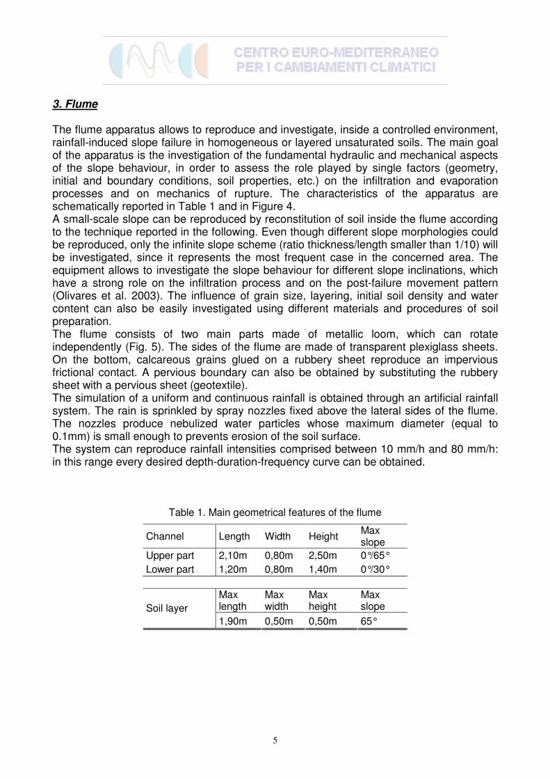
3. Flume
The flume apparatus allows to reproduce and investigate, inside a controlled environment, rainfall-induced slope failure in homogeneous or layered unsaturated soils. The main goal of the apparatus is the investigation of the fundamental hydraulic and mechanical aspects of the slope behaviour, in order to assess the role played by single factors (geometry, initial and boundary conditions, soil properties, etc.) on the infiltration and evaporation processes and on mechanics of rupture. The characteristics of the apparatus are schematically reported in Table 1 and in Figure 4. A small-scale slope can be reproduced by reconstitution of soil inside the flume according to the technique reported in the following. Even though different slope morphologies could be reproduced, only the infinite slope scheme (ratio thickness/length smaller than 1/10) will be investigated, since it represents the most frequent case in the concerned area. The equipment allows to investigate the slope behaviour for different slope inclinations, which have a strong role on the infiltration process and on the post-failure movement pattern (Olivares et al. 2003). The influence of grain size, layering, initial soil density and water content can also be easily investigated using different materials and procedures of soil preparation. The flume consists of two main parts made of metallic loom, which can rotate independently (Fig. 5). The sides of the flume are made of transparent plexiglass sheets. On the bottom, calcareous grains glued on a rubbery sheet reproduce an impervious frictional contact. A pervious boundary can also be obtained by substituting the rubbery sheet with a pervious sheet (geotextile). The simulation of a uniform and continuous rainfall is obtained through an artificial rainfall system. The rain is sprinkled by spray nozzles fixed above the lateral sides of the flume. The nozzles produce nebulized water particles whose maximum diameter (equal to 0.1mm) is small enough to prevents erosion of the soil surface. The system can reproduce rainfall intensities comprised between 10 mm/h and 80 mm/h: in this range every desired depth-duration-frequency curve can be obtained.
Table 1. Main geometrical features of the flume
Channel Length Width Height Max slope
Upper part 2,10m 0,80m 2,50m 0°/65°
Lower part 1,20m 0,80m 1,40m 0°/30°
Max length
Max width
Max height
Max slope Soil layer
1,90m 0,50m 0,50m 65°

6
Figure 4. The instrumented flume (LT = laser transducer; MT = minitensiometer; PT = pressure transducer; TDR = TDR probe; VC = digital video-camera): a) cross-section; b) plan-view
7
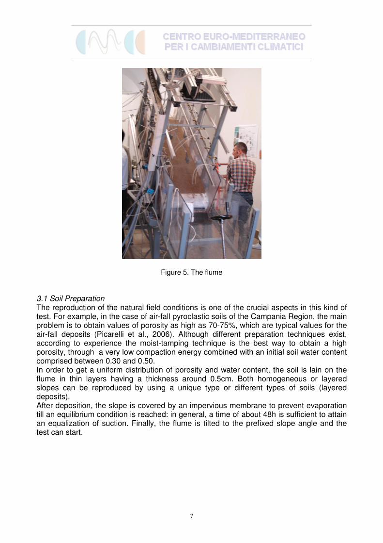
Figure 5. The flume
3.1 Soil Preparation The reproduction of the natural field conditions is one of the crucial aspects in this kind of test. For example, in the case of air-fall pyroclastic soils of the Campania Region, the main problem is to obtain values of porosity as high as 70-75%, which are typical values for the air-fall deposits (Picarelli et al., 2006). Although different preparation techniques exist, according to experience the moist-tamping technique is the best way to obtain a high porosity, through a very low compaction energy combined with an initial soil water content comprised between 0.30 and 0.50. In order to get a uniform distribution of porosity and water content, the soil is lain on the flume in thin layers having a thickness around 0.5cm. Both homogeneous or layered slopes can be reproduced by using a unique type or different types of soils (layered deposits). After deposition, the slope is covered by an impervious membrane to prevent evaporation till an equilibrium condition is reached: in general, a time of about 48h is sufficient to attain an equalization of suction. Finally, the flume is tilted to the prefixed slope angle and the test can start.

8
3.2 Monitoring system The flume is instrumented with different devices able to measure any change of soil properties (water content, degree of saturation), state of stress (suction, pore pressure) and displacement pattern (Olivares et al., 2008). The characteristics of each instrument (Table 2 and Fig. 6) are described in the following.
Table 2. Main characteristics of the devices Measurement Device Type Sensor Transducer
Operating
range Linearity Hysteresis Output
Sampling
frequency
Diameter Height
Matric suction TensiometerJet-fill
Small-tip
Pouros
ceramic cup6mm 25mm
Current
transducer0 to 100kPa 0.25% <1% 4-20mA 750Hz
Measurement Device
Rods diameter Length
Water content
profile along zTDR apparatus 1mm up to 95mm 90ps 200ps
1cm at
θ=0,1m3/m
3
2cm at
θ=0,2m3/m
3 15s 0,01m3/m
3
Measurement Device Type SensorMeasuring
range Resolution Linearity Output
Operating
temperature
Sampling
frequency
ILD 1400-50Laser CCD-
array50mm 5µm +/-0.2% 4-20mA 0 to 55°C 1kHz
ILD 1400-100Laser CCD-
array100mm 20µm +/-0.2% 4-20mA 0 to 55°C 1kHz
Measurement Device Type Sensor Frame rate Resolution Pixel size Video output Image areaSampling
frequency
Displacements ux;
uy
Digital camera Basler A101p
2/3" HAD
interline
transfer
progressive
11.75 fps 1300 x 10306.7 µm x 6.7
µmRS-644 50cm x 50cm 0.1Hz
Measurement Device Type SensorOperating
range Resolution Linearity Output
Operating
temperature
Natural
frequency
Diameter Height
Pore water
pressure
Pore pressure
transducerPDCR81
Integrated
silicon strain
gauge
6.3mm 11.4mm 0 to 35kPa 0.1% f.s. +/-0.2% 0-35mV -20 to120°C 55kHz
Measurement Device Type SensorOperating
range Resolution
Maximum
temporal
resolution
Diameter Height
Rainfall intensity Rain gauge PCR918N Tipping bucket 113.5mm 145mm 0 to 999mm/h 1mm/h 1min
Temperature -5° to 50°C 0.1°C 1min
Relative humidity 2% to 98% 1% 1min
Dimension sensor
Dimension
Displacements uzSensor
displacement
65mm x 20mm x 50mm
65mm x 20mm x 50mm
Dimension metallic probeVolumetric
water
content
Housing size (L x W x H)
Housing size (L x W x H)
45mm x 62mm x 62mm
Nominal
pulse rise
time
Observed
pulse rise
timeExternal probe spacing
13mm
Dimension sensor
Maximum
temporal
resolution
Maximum spatial resolution
BTHR918N

9
Displacement laser transducer
TDR probe
Minitensiometer
Displacement laser transducer
TDR probe
Minitensiometer
Figure 6. Scheme of the instrumented model slope
Tensiometers During the infiltration (and/or the evaporation) process, the slope behaviour is strictly related to matric suction. This is measured by conventional miniaturized jet-fill type tensiometers (Table 2, Fig. 7), which consist of a high air-entry (100kPa) porous ceramic cup, 25mm high and 6mm wide, connected to a pressure-measuring device through a small-bore tube filled with de-aired water. The cups are located everywhere along the slope by manual installation at every desired depths. The instruments are connected to a PC for data acquisition and storage.
protezione con tubo di nylon
punta porosa in
ceramica
tubo per lo
spurgo dell’aria
corpo
tensiometrico
valvola per lo
spurgo dell’aria
O-ring di
tenuta
manometro
tappo per aggiunta di
acqua
O-ring di
tenuta
adattatore
vite di tenuta
adattatore
anello di tenuta
Figure 7. Small-tip tensiometers with flexible coaxial tubing

10
TDR device The experimental setup of the Time Domain Reflectometry (TDR) is shown in Figure 8. A three rods metallic probe, vertically installed in the soil, is connected to the cable tester, allowing to measure the water content profile within the entire soil layer. The main characteristics of the experimental apparatus are given in Table 2.
Figure 8. TDR probe
TDR measurement is based on the strong correlation between bulk dielectric permittivity εr
of wet soil and its volumetric water content θ (Campbell, 1990). Usually, soil permittivity is estimated by measuring the mean speed of an electromagnetic pulse travelling along a metallic probe buried into the soil, providing the mean water content in a cylindrical volume around the probe, with diameter comparable to probe external rods spacing (tab. 2).
Several expressions of εr(θ) relationship are available in the literature, empirically stated (Topp et al., 1980) as well as based on semi-analytical approach to dielectric mixing models (Roth et al., 1990). Recently, several studies have been dedicated to the development of innovative methods to extract more information from TDR measurements, in order to estimate non homogeneous moisture profiles along the probe axis. In particular, the inverse profiling method proposed by Greco (2006) will be used. Rainfall and temperature gauges During the test, rain intensity and air temperature are measured respectively by a rain gauge and a standard thermocouple, controlled with a weather station. Cumulated rain height is measured every minute. Rain intensity is calculated by differentiating the hyetogram. Laser sensors and Particle Image Velocimetry system Soil surface displacements are monitored by means of laser sensors and a Particle Image Velocimetry (PIV) system. The laser sensors (Fig. 9) allow to monitor settlements of the ground surface. The instruments, which exploit the principle of optical triangulation, are located above the ground surface with the optical axis perpendicular to the monitored ground surface. The

11
roughness of the target surface and the presence of drops of water could produce a noise that in the current applications is nevertheless acceptable.
Figure 9. Laser displacement transducer
The flume is also equipped with a PIV system, consisting of two high definition digital video-cameras (Fig. 10) located over the ground surface connected to digital image acquisition boards, designed to monitor and store the images with 0.1Hz frequency sampling. The cameras are motorized and can move with predefined acceleration or velocity to follow the movement of soil particles. Each camera is placed at such a distance from the soil surface to capture an image of 50cmx50cm, thus exploiting the maximum definition (3 mega-pixel). The image contains a number of particles (about 0.1mm in diameter) sufficient to correctly define the displacement field through a PIV technique. These characteristics allow to properly investigate either the pre-failure or the post-failure stage.
Figure 10. High definition video-cameras installed above the flume
12
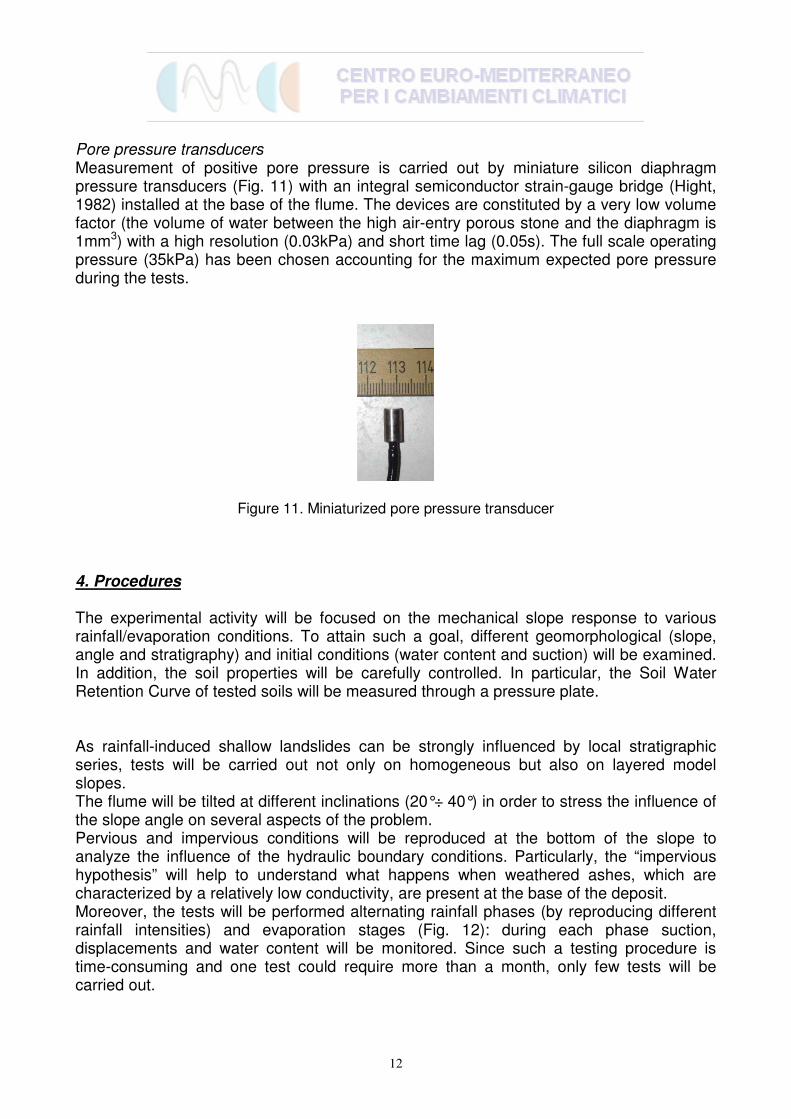
Pore pressure transducers Measurement of positive pore pressure is carried out by miniature silicon diaphragm pressure transducers (Fig. 11) with an integral semiconductor strain-gauge bridge (Hight, 1982) installed at the base of the flume. The devices are constituted by a very low volume factor (the volume of water between the high air-entry porous stone and the diaphragm is 1mm3) with a high resolution (0.03kPa) and short time lag (0.05s). The full scale operating pressure (35kPa) has been chosen accounting for the maximum expected pore pressure during the tests.
Figure 11. Miniaturized pore pressure transducer
4. Procedures
The experimental activity will be focused on the mechanical slope response to various rainfall/evaporation conditions. To attain such a goal, different geomorphological (slope, angle and stratigraphy) and initial conditions (water content and suction) will be examined. In addition, the soil properties will be carefully controlled. In particular, the Soil Water Retention Curve of tested soils will be measured through a pressure plate. As rainfall-induced shallow landslides can be strongly influenced by local stratigraphic series, tests will be carried out not only on homogeneous but also on layered model slopes. The flume will be tilted at different inclinations (20°÷ 40°) in order to stress the influence of the slope angle on several aspects of the problem. Pervious and impervious conditions will be reproduced at the bottom of the slope to analyze the influence of the hydraulic boundary conditions. Particularly, the “impervious hypothesis” will help to understand what happens when weathered ashes, which are characterized by a relatively low conductivity, are present at the base of the deposit. Moreover, the tests will be performed alternating rainfall phases (by reproducing different rainfall intensities) and evaporation stages (Fig. 12): during each phase suction, displacements and water content will be monitored. Since such a testing procedure is time-consuming and one test could require more than a month, only few tests will be carried out.

13
α = 20°÷ 40° α = 20°÷ 40°a) b)α = 20°÷ 40° α = 20°÷ 40°a) b)
Figure 12. Testing procedures: a) infiltration stage; b) evaporation stage
5. Conclusions
The equipment illustrated above will be used in the prosecution of the research in order to investigate the mechanical and hydraulic behaviour of typical Campanian sloping deposits constituted by unsaturated pyroclastic soils. According to the sketch proposed in Figure 13, the laboratory tests will be used to check the numerical model for prediction of slope response as a consequence of meteorological events. In particular, laboratory tests: - the experimental results may give further inputs to verify if the numerical model is able to capture all the significant phenomenological aspects of the slope response, contributing to its refinement; - through the back-analysis of the experiments, the correct values of the geotechnical parameters used in the geotechnical model can be checked; - using the physical model as a real slope, it can be verified if it is able to timely predict the slope collapse.
NUMERICAL MODEL
FOR PREDICTION OF SLOPE RESPONSE
METEOROLOGICAL MODEL
STANDARD TESTS
SLOPE STABILITY EVALUATION
PHYSICAL MODEL
LABORATORYNUMERICAL MODEL
FOR PREDICTION OF SLOPE RESPONSE
METEOROLOGICAL MODEL
STANDARD TESTS
SLOPE STABILITY EVALUATION
PHYSICAL MODEL
LABORATORY
Figure 13. Schematic procedure for slope stability evaluation

14
6. References
Campbell J.E. (1990). Dielectric properties and influence of conductivity in soils at one to fifty megahertz. Soil Science Society of American Journal 54: 332–341 Fredlund D.G., Rahardjo H. (1993). Soil Mechanics for unsaturated soils. John Wiley & Sons, Inc. Greco R. (2006). Soil water content inverse profiling from single TDR waveforms, Journal of hydrology, pp. 325-339 Hight, D.W. (1982). A simple piezometer probe for the routine measurement of pore pressure in triaxial tests on saturated soils. Technical note. Geotechnique, 32, pp. 397-401 Hilf J.W. (1956). An investigation of Pore-Water Pressure in Compacted Cohesive Soils. Ph.D. dissertation, Tech. Memo. No. 654, U.S. Dep. of the Interior, Bureau of Reclamation, Design and Construction Div., Denver, CO, p. 654. Olivares L., Andreozzi L., Damiano E., Avolio B., Picarelli L. (2003). Hydrological response of a steep slope in pyroclastic unsaturated soils. Proc. Int. Conf. on Fast Slope Movements – Prediction and Prevention for Risk Mitigation, Napoli Olivares, L., Damiano, E., Greco, R., Zeni, L., Picarelli, L., Minardo, A., Guida, A., and Bernini, E. (2008). “An instrumented flume for investigation of the mechanics of landslides in unsaturated granular soils”. Submitted for publication in Geotechnical Testing Journal Picarelli L., Evangelista A., Rolandi G., Paone A., Nicotera M.V., Olivares L., Scotto di Santolo A., Lampitiello S., Rolandi M. (2006). Mechanical properties of pyroclastic soils in Campania Region. Invited paper, 2nd Int. Workshop on Characterisation and Engineering Properties of Natural Soils, Singapore Roth K., Schulin R., Fluhler H., Attinger W. (1990). Calibration of time domain reflectometry for water content measurement using a composite dielectric approach. Water Resources Research 26(10), pp. 2267–2273 Topp G.C., Davis J.L., Annan A.P. (1980). Electromagnetic determination of soil water content: measurements in coaxial transmission lines. Water Resources Research 16, pp. 574–582