
Buffer Overrun Detection using Linear Programming and Static Analysis
HALMSTAD • CHICAGO • KARLSRUHE • TOKYO • BEIJING • MILANO • MULHOUSE • COVENTRY • PUNE • COPENHAGEN
HMS Industrial NetworksMailing address: Box 4126, 300 04 Halmstad, SwedenVisiting address: Stationsgatan 37, Halmstad, Sweden
Connecting DevicesTM
E-mail: [email protected] www.hms-networks.com
X-Gateway Interface Addendum
Interbus Fibre Optic SlaveDoc: HMSI-27-260
Rev: 2.00

Important User Information
This document is intended to provide a good understanding of the functionality offered by the Interface described here.
The reader is expected to be familiar with high level software design, and communication systems in general. The use of advanced interface-specific functionality may require in-depth knowledge of networking internals and/or information from the network specifications. In such cases, the persons responsible for the implementation of this product should either obtain the necessary specifications to gain sufficient knowledge, or alternatively limit the implementation in such a way that this is not necessary.
Liability
Every care has been taken in the preparation of this manual. Please inform HMS Industrial Networks AB of any inaccuracies or omissions. The data and illustrations found in this document are not binding. We, HMS Industrial Networks AB, reserve the right to modify our products in line with our policy of continuous product development. The information in this document is subject to change without notice and should not be considered as a commit-ment by HMS Industrial Networks AB. HMS Industrial Networks AB assumes no responsibility for any errors that may appear in this document.
There are many applications of this product. Those responsible for the use of this device must ensure that all the necessary steps have been taken to verify that the applications meet all performance and safety requirements in-cluding any applicable laws, regulations, codes, and standards.
HMS Industrial Networks AB will under no circumstances assume liability or responsibility for any problems that may arise as a result from the use of undocumented features, timing, or functional side effects found outside the documented scope of this product. The effects caused by any direct or indirect use of such aspects of the product are undefined, and may include e.g. compatibility issues and stability issues.
The examples and illustrations in this document are included solely for illustrative purposes. Because of the many variables and requirements associated with any particular implementation, HMS Industrial Networks AB cannot assume responsibility for actual use based on these examples and illustrations.
Intellectual Property Rights
HMS Industrial Networks AB has intellectual property rights relating to technology embodied in the product de-scribed in this document. These intellectual property rights may include patents and pending patent applications in the US and other countries.
Trademark Acknowledgements
Anybus ® is a registered trademark of HMS Industrial Networks AB. All other trademarks are the property of their respective holders.
WARNING: This is a class A product. in a domestic environment this product may cause radio interference in which case the user may be required to take adequate measures.
ESD Note: This product contains ESD (Electrostatic Discharge) sensitive parts that may be damaged if ESD control procedures are not followed. Static control precautions are required when handling the product. Failure to observe this may cause damage to the product.
Interbus Fibre Optic Slave X-Gateway Interface Addendum
Copyright© HMS Industrial Networks AB
Doc: HMSI-27-260, Rev: 2.00
May 2014
!

Preface About This Document
How To Use This Document ............................................................................................................ P-3
Important User Information .............................................................................................................. P-3
Related Documents.............................................................................................................................. P-4
Document History ............................................................................................................................... P-4
Conventions & Terminology.............................................................................................................. P-4
Support .................................................................................................................................................. P-4
Chapter 1 About the Interbus Fibre Optic Slave Interface
General Description..............................................................................................................................1-5
Features...................................................................................................................................................1-5
External View ........................................................................................................................................1-6Interface Status LEDs .................................................................................................................1-6Interface Connectors.......................................................................................................................1-6
Chapter 2 Data Exchange
General Information.............................................................................................................................2-7
Input Data (Gateway to Interbus) ......................................................................................................2-7
Output Data (Interbus to Gateway) ...................................................................................................2-8
PCP Object Mapping............................................................................................................................2-8Output Buffer ...............................................................................................................................2-8Input Buffer ..................................................................................................................................2-9
Chapter 3 Installation and Configuration
Node Address Configuration ............................................................................................................3-10
Operating Baudrate.............................................................................................................................3-10
Network Configuration ......................................................................................................................3-10
Appendix A Calculating the PCP Transmission Time
Appendix B Technical Specification
Network Interface Details ................................................................................................................ B-12
Table of Contents
Table of Contents

Doc: HMSI-27-260, Rev: 2.00 X-Gateway Interface Addendum: Interbus Fibre Optic Slave
Preface
P. About This Document
P.1. How To Use This Document
This document describes network specific features and procedures needed when operating the Interbus Fibre Optic Slave Interface for the Anybus X-Gateway. For general information and operating instruc-tions for the Anybus X-Gateway, consult the Anybus-X Generic Gateway User Manual.
The reader of this document is expected to be familiar with Interbus networking technology, and com-munication systems in general.
For further information, documentation etc., please visit www.anybus.com.
P.2. Related Documents
P.3. Document History
Revision List
P.4. Conventions & Terminology
The following conventions are used throughout this document:
• Numbered lists provide sequential steps
• Bulleted lists provide information, not procedural steps
• The term ‘X-Gateway’ refers to the Anybus X-Gateway
• The term ‘Slave interface’ refers to the Interbus Fibre Optic Slave interface for the X-Gateway.
• The term ‘user manual’ refers to the Anybus-X Generic Gateway User Manual.
• Hexadecimal values are written in the format NNNNh, where NNNN is the hexadecimal value.
• 16/32 bit values are generally stored in Motorola (big endian) format unless otherwise stated.
P.5. Support
For general contact information and support, please refer to the contact and support pages at www.anybus.com.
Document AuthorAnybus-X Generic Gateway User Manual HMSAnybus-S Interbus 2Mbit Fibre Optic Fieldbus Appendix HMSInterbus Fibre Optic Slave Interface, Installation Sheet HMS
Revision Date Author Chapter Description1.00 2004-04-02 PeP All First release1.01 2007-06-14 PeP All General update2.00 May 2014 SDa All New hardware and Anybus Confiiguration Manager
Doc: HMSI-27-260, Rev: 2.00 X-Gateway Interface Addendum: Interbus Fibre Optic Slave
Chapter 1
1. About the Interbus Fibre Optic Slave Interface
1.1. General Description
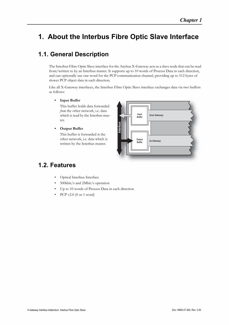
The Interbus Fibre Optic Slave interface for the Anybus X-Gateway acts as a slave node that can be read from/written to by an Interbus master. It supports up to 10 words of Process Data in each direction, and can optionally use one word for the PCP communication channel, providing up to 512 bytes of slower PCP object data in each direction.
Like all X-Gateway interfaces, the Interbus Fibre Optic Slave interface exchanges data via two buffers as follows:
• Input Buffer
This buffer holds data forwarded from the other network, i.e. data which is read by the Interbus mas-ter.
• Output Buffer
This buffer is forwarded to the other network, i.e. data which is written by the Interbus master.
1.2. Features
• Optical Interbus Interface
• 500kbit/s and 2Mbit/s operation
• Up to 10 words of Process Data in each direction
• PCP v2.0 (0 or 1 word)
Inte
rbus
OutputBuffer (to Gateway)
InputBuffer
(from Gateway)

About the Interbus Fibre Optic Slave Interface 1-7
Doc: HMSI-27-260, Rev: 2.00 X-Gateway Interface Addendum: Interbus Fibre Optic Slave
1.3. External View
1.3.1. Interface Status LEDs
1.3.2. Interface Connectors
For further details on the USB Gateway Config connector, see the X-gateway user manual.
LED Colour Indication
Gateway Status
See the user manual for further details.
BA Green Bus active
RD Yellow Remote bus disabled
FO2 Yellow Fibre optic warning for Bus Out
FO1 Yellow Fibre optic warning for Bus In
# Description
1 Fibre optic transmit (Bus In)
2 Fibre optic receive (Bus In)
3 Fibre optic transmit (Bus Out)
4 Fibre optic receive (Bus Out)
5 Baudrate jumper.See “Operating Baudrate” on page 10.
6 Gateway power connectorConsult the X-gateway user manual for further details.
Top-mounted Interbus interface
Bottom-mounted Interbus interface
BARDFO2FO1
Gateway status
Gateway status
USB Gateway Config Connector
Front View
Bottom-mounted Interface
Top-mounted Interface
BARDFO2FO1
12345
51 2 3 4
2M500k
500k2M
6

Doc: HMSI-27-260, Rev: 2.00 X-Gateway Interface Addendum: Interbus Fibre Optic Slave
Chapter 2
2. Data Exchange
2.1. General Information
On Interbus, network data is represented as Process Data and PCP. The Slave interface supports up to 10 words of data in each direction, out of which 1 word may be used internally for the PCP communication channel.
The amount of Process Data and PCP is specified through the Gateway Config Interface. Note that specifying 10 words of Process Data effectively shuts down the PCP channel, prevent-ing PCP communication alltogether.
2.2. Input Data (Gateway to Interbus)
Depending on the type of gateway and how it has been configured, up to 5 words of the data produced by the gateway may be occupied with status information.
Note: The Live List is only available on master-slave gateway versions.
Example A:Process Data size = 6 words (12 bytes)PCP size = 4 (8 bytes)Live List = EnabledControl & Status Word = Enabled
Example B:Process Data size = 5 words (10 bytes)PCP size = 4 words (8 bytes)Live List = DisabledControl & Status Word = Enabled
Inte
rbus
PCP
Process Data
Control Word
(from Gateway)
(to Gateway)
PCP
Process Data
Status Word
Live List
PCP
(4wo
rds)
Proc
essD
ata(6
word
s)
Status Word (1 word)
Live List (4 words)
Data fromgateway (5 words) PC
P(4
wor
ds)
Proc
ess D
ata(5
wor
ds)
Status Word (1 word)
Live List (8 bytes)
Data fromgateway (8 words)
Data Exchange 2-9
Doc: HMSI-27-260, Rev: 2.00 X-Gateway Interface Addendum: Interbus Fibre Optic Slave
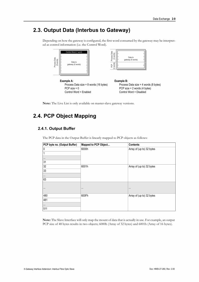
2.3. Output Data (Interbus to Gateway)
Depending on how the gateway is configured, the first word consumed by the gateway may be interpret-ed as control information (i.e. the Control Word).
Note: The Live List is only available on master-slave gateway versions.
2.4. PCP Object Mapping
2.4.1. Output Buffer
The PCP data in the Output Buffer is linearly mapped to PCP objects as follows:
Note: The Slave Interface will only map the mount of data that is actually in use. For example, an output PCP size of 48 bytes results in two objects; 6000h (Array of 32 bytes) and 6001h (Array of 16 bytes).
Example A:Process Data size = 8 words (16 bytes)PCP size = 0Control Word = Enabled
Example B:Process Data size = 4 words (8 bytes)PCP size = 2 words (4 bytes)Control Word = Disabled
PCP byte no. (Output Buffer) Mapped to PCP Object... Contents0 6000h Array of (up to) 32 bytes1...3132 6001h Array of (up to) 32 bytes33...63
... ... ...
480 600Fh Array of (up to) 32 bytes481...511
Proc
ess D
ata(8
wor
ds)
Control Word (1 word)
Data togateway (6 words)
PCP
(2 w
ords
)Pr
oces
s Data
(4 w
ords
)
Data togateway (6 words)

Data Exchange 2-10
Doc: HMSI-27-260, Rev: 2.00 X-Gateway Interface Addendum: Interbus Fibre Optic Slave
2.4.2. Input Buffer
The PCP data in the Input Buffer is linearly mapped to PCP objects as follows:
Note: The Slave Interface will only map the mount of data that is actually in use. For example, an input PCP size of 40 bytes results in two objects; 6040h (Array of 32 bytes) and 6041h (Array of 8 bytes).
PCP byte no. (Input Buffer) Mapped to PCP Object... Contents0 6040h Array of (up to) 32 bytes1...3132 6041h Array of (up to) 32 bytes33...63
... ... ...
480 604Fh Array of (up to) 32 bytes481...511

Doc: HMSI-27-260, Rev: 2.00 X-Gateway Interface Addendum: Interbus Fibre Optic Slave
Chapter 3
3. Installation and Configuration
3.1. Node Address Configuration
Unlike most other network systems, Interbus does not use any switches etc. to set the node address. In-stead, each node is automatically assigned a node address based on its physical location in the network.
3.2. Operating Baudrate
The Slave interface supports two baudrates; 500kbps and 2Mbps. The baudrate is specified using the on-board jumper, see “Interface Connectors” on page 6.
Note: Depending on if the Slave interface is top or bottom-mounted, the orientation of the jumper will be different.
3.3. Network Configuration
Normally, an Interbus network is self-configurating, i.e. provided that the Slave interface is set to operate at the same baudrate as the rest of the system, the interface should be detected and added automatically.
Note however that PCP communication will require support in the Interbus master.
Doc: HMSI-27-260, Rev: 2.00 X-Gateway Interface Addendum: Interbus Fibre Optic Slave
Appendix A
A. Calculating the PCP Transmission Time
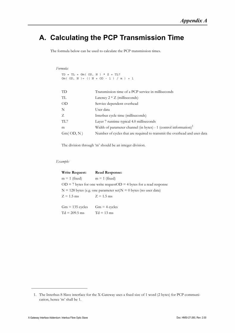
The formula below can be used to calculate the PCP transmission times.
Formula:TD = TL + Gm( OD, N ) * Z + TL7Gm( OD, N )= (( N + OD - 1 ) / m ) + 1
TD Transmission time of a PCP service in milliseconds
TL Latency 2 * Z (milliseconds)
OD Service dependent overhead
N User data
Z Interbus cycle time (milliseconds)
TL7 Layer 7 runtime typical 4.0 milliseconds
m Width of parameter channel (in bytes) - 1 (control information)1
Gm( OD, N ) Number of cycles that are required to transmit the overhead and user data
The division through ‘m’ should be an integer division.
Example:
Write Request: Read Response:
m = 1 (fixed) m = 1 (fixed)
OD = 7 bytes for one write requestOD = 4 bytes for a read response
N = 128 bytes (e.g. one parameter set)N = 0 bytes (no user data)
Z = 1.5 ms Z = 1.5 ms
Gm = 135 cycles Gm = 4 cycles
Td = 209.5 ms Td = 13 ms
1. The Interbus-S Slave interface for the X-Gateway uses a fixed size of 1 word (2 bytes) for PCP communi-cation, hence ‘m’ shall be 1.
Doc: HMSI-27-260, Rev: 2.00 X-Gateway Interface Addendum: Interbus Fibre Optic Slave
Appendix B
B. Technical Specification
B.1. Network Interface Details
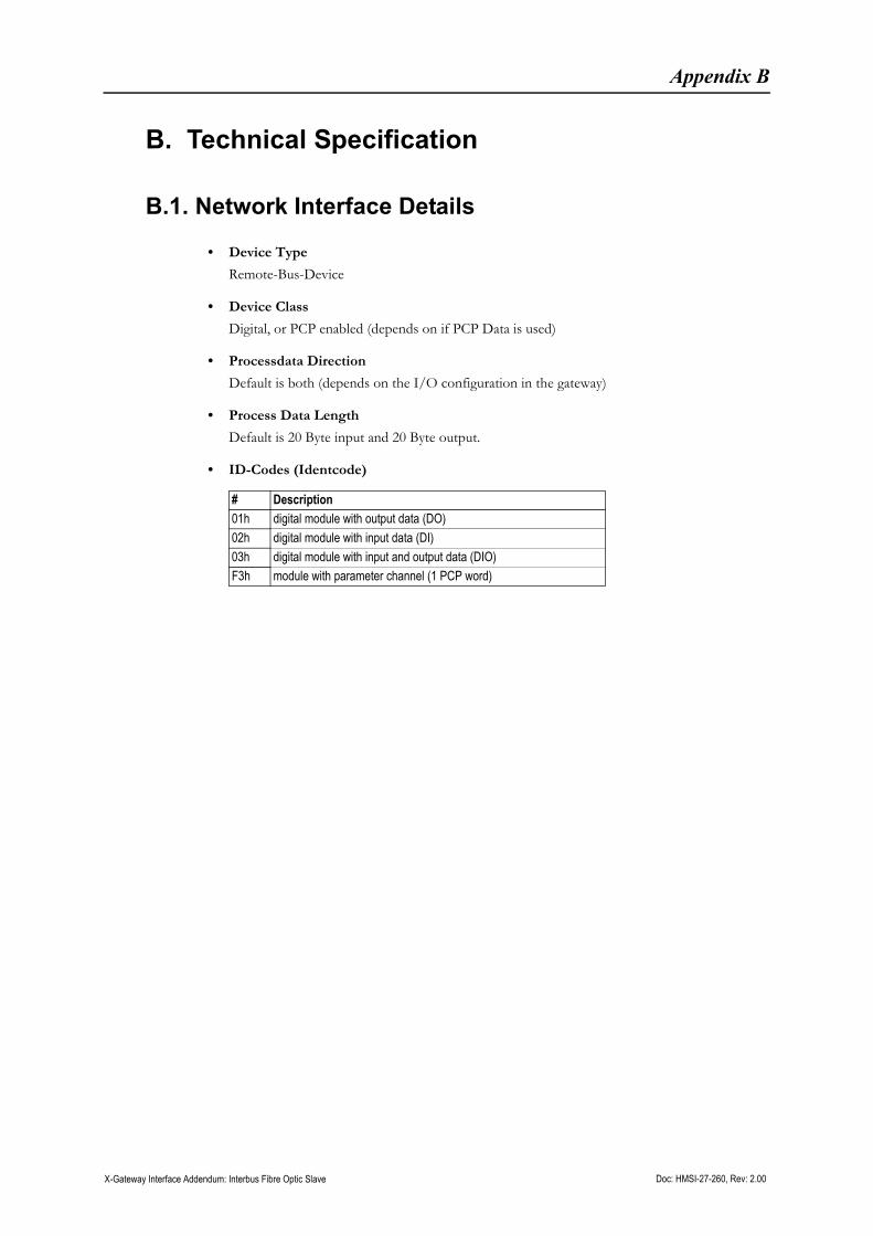
• Device Type
Remote-Bus-Device
• Device Class
Digital, or PCP enabled (depends on if PCP Data is used)
• Processdata Direction
Default is both (depends on the I/O configuration in the gateway)
• Process Data Length
Default is 20 Byte input and 20 Byte output.
• ID-Codes (Identcode)
# Description01h digital module with output data (DO)02h digital module with input data (DI)03h digital module with input and output data (DIO)F3h module with parameter channel (1 PCP word)