I307IGB03 11 DME D310 T2 - Lovato Electric · Volendo è anche possibile programmare il multimetro...
18
Doc: MHIT103D0408.doc 07/03/2011 p. 1 / 18 DME D310 T2 DME D310 T2 Contatore di energia trifase Three-phase energy meter con ingressi di corrente da TA with CT current inputs MANUALE OPERATIVO INSTRUCTIONS MANUAL Prima di qualsiasi intervento sullo strumento, togliere tensione dagli ingressi di misura e di alimentazione e cortocircuitare i trasformatori di corrente. Il costruttore non si assume responsabilità in merito alla sicurezza elettrica in caso di utilizzo improprio del dispositivo. I prodotti descritti in questo documento sono suscettibili in qualsiasi momento di evoluzioni o di modifiche. Le descrizioni ed i dati a catalogo non possono pertanto avere alcun valore contrattuale. Un interruttore o disgiuntore va compreso nell’impianto elettrico dell’edificio. Esso deve trovarsi in stretta vicinanza dell’apparecchio ed essere facilmente raggiungibile da parte dell’operatore. Deve essere marchiato come il dispositivo di interruzione dell’apparecchio: IEC/ EN 61010-1 § 6.12.2.1. Installare lo strumento in contenitore e/o quadro elettrico con grado di protezione minimo IP40. Pulire lo strumento con panno morbido, non usare prodotti abrasivi, detergenti liquidi o solventi. Before any maintenance operation on the device, remove all the voltages from measuring and supply inputs and short-circuit the CT input terminals. The manufacturer cannot be held responsible for electrical safety in case of improper use of the equipment. Products illustrated herein are subject to alteration and changes without prior notice. Technical data and descriptions in the documentation are accurate, to the best of our knowledge, but no liabilities for errors, omissions or contingencies arising there from are accepted. A circuit breaker must be included in the electrical installation of the building. It must be installed close by the equipment and within easy reach of the operator. It must be marked as the disconnecting device of the equipment: IEC /EN 61010-1 § 6.12.2.1. Fit the instrument in an enclosure or cabinet with minimum IP40 degree protection. Clean the instrument with a soft dry cloth; do not use abrasives, liquid detergents or solvents. Indice Pagina Introduzione 2 Descrizione 2 Funzione dei tasti frontali 2 Visualizzazione delle misure 3 Tabella delle pagine del display 4 Pagina contatori di energia 5 Pagina contaore 5 Pagina grafico trend 5 Pagina contatori 6 Menu principale 7 Accesso tramite password 7 Espandibilità 8 Risorse aggiuntive 8 Ingressi, uscite, variabili interne, contatori 9 Soglie limite 9 Variabili da remoto 10 Tariffe 10 Impostazione dei parametri (set-up) 11 Tabella dei parametri 12 Menu comandi 15 Test di collegamento 16 Caratteristiche tecniche 17 Schemi di connessione 18 Disposizione morsetti 18 Dimensioni meccaniche 18 Index Page Introduction 2 Description 2 Keyboard functions 2 Measurement viewing 3 Table of display pages 4 Energy meters page 5 Hour counters page 5 Trend graph page 5 Counters page 6 Main menu 7 Password access 7 Expandability 8 Additional resources 8 Inputs, outputs, internal variables, counters 9 Limit thresholds 9 Remote-controlled variables 10 Tariffs 10 Setting of parameters (set-up) 11 Table of parameters 12 Commands menu 15 Wiring test 16 Technical characteristics 17 Wiring diagrams 18 Terminal arrangement 18 Mechanical dimensions 18 I 307 IGB0311 ATTENZIONE!! Leggere attentamente il manuale prima dell’utilizzo e l’installazione. Questi apparecchi devono essere installati da personale qualificato, nel rispetto delle vigenti normative impiantistiche, allo scopo di evitare danni a persone o cose. WARNING! Carefully read the manual before the installation or use. This equipment is to be installed by qualified personnel, complying to current standards, to avoid damages or safety hazards.
Transcript of I307IGB03 11 DME D310 T2 - Lovato Electric · Volendo è anche possibile programmare il multimetro...

Doc: MHIT103D0408.doc 07/03/2011 p. 1 / 18
DME D310 T2 DME D310 T2 Contatore di energia trifase Three-phase energy meter con ingressi di corrente da TA with CT current inputs
MANUALE OPERATIVO INSTRUCTIONS MANUAL
� Prima di qualsiasi intervento sullo strumento, togliere tensione dagli ingressi di misura e di alimentazione e cortocircuitare i trasformatori di corrente. � Il costruttore non si assume responsabilità in merito alla sicurezza elettrica in caso di utilizzo improprio del dispositivo. � I prodotti descritti in questo documento sono suscettibili in qualsiasi momento di evoluzioni o di modifiche. Le descrizioni ed i dati a catalogo non possono pertanto avere alcun valore contrattuale. � Un interruttore o disgiuntore va compreso nell’impianto elettrico dell’edificio. Esso deve trovarsi in stretta vicinanza dell’apparecchio ed essere facilmente raggiungibile da parte dell’operatore. Deve essere marchiato come il dispositivo di interruzione dell’apparecchio: IEC/ EN 61010-1 § 6.12.2.1. � Installare lo strumento in contenitore e/o quadro elettrico con grado di protezione minimo IP40. � Pulire lo strumento con panno morbido, non usare prodotti abrasivi, detergenti liquidi o solventi.
� Before any maintenance operation on the device, remove all the voltages from measuring and supply inputs and short-circuit the CT input terminals. � The manufacturer cannot be held responsible for electrical safety in case of improper use of the equipment. � Products illustrated herein are subject to alteration and changes without prior notice. � Technical data and descriptions in the documentation are accurate, to the best of our knowledge, but no liabilities for errors, omissions or contingencies arising there from are accepted. � A circuit breaker must be included in the electrical installation of the building. It must be installed close by the equipment and within easy reach of the operator. It must be marked as the disconnecting device of the equipment: IEC /EN 61010-1 § 6.12.2.1. � Fit the instrument in an enclosure or cabinet with minimum IP40 degree protection. � Clean the instrument with a soft dry cloth; do not use abrasives, liquid detergents or solvents.
Indice
Pagina Introduzione 2 Descrizione 2 Funzione dei tasti frontali 2 Visualizzazione delle misure 3 Tabella delle pagine del display 4 Pagina contatori di energia 5 Pagina contaore 5 Pagina grafico trend 5 Pagina contatori 6 Menu principale 7 Accesso tramite password 7 Espandibilità 8 Risorse aggiuntive 8 Ingressi, uscite, variabili interne, contatori 9 Soglie limite 9 Variabili da remoto 10 Tariffe 10 Impostazione dei parametri (set-up) 11 Tabella dei parametri 12 Menu comandi 15 Test di collegamento 16 Caratteristiche tecniche 17 Schemi di connessione 18 Disposizione morsetti 18 Dimensioni meccaniche 18
Index
Page Introduction 2 Description 2 Keyboard functions 2 Measurement viewing 3 Table of display pages 4 Energy meters page 5 Hour counters page 5 Trend graph page 5 Counters page 6 Main menu 7 Password access 7 Expandability 8 Additional resources 8 Inputs, outputs, internal variables, counters 9 Limit thresholds 9 Remote-controlled variables 10 Tariffs 10 Setting of parameters (set-up) 11 Table of parameters 12 Commands menu 15 Wiring test 16 Technical characteristics 17 Wiring diagrams 18 Terminal arrangement 18 Mechanical dimensions 18
I307
IGB
0311
ATTENZIONE!! � Leggere attentamente il manuale prima dell’utilizzo e l’installazione. � Questi apparecchi devono essere installati da personale qualificato, nel rispetto delle vigenti normative impiantistiche, allo scopo di evitare danni a persone o cose.
WARNING! � Carefully read the manual before the installation or use. � This equipment is to be installed by qualified personnel,
complying to current standards, to avoid damages or safety hazards.

Doc: MHIT103D0408.doc 07/03/2011 p. 2 / 18
Introduzione Il contatore di energia DME310T2 è stato progettato per unire la massima semplicità di utilizzo con una ampia scelta di funzioni avanzate. L’ottima accuratezza delle misure, la semplicità di installazione e di utilizzo ne fanno una scelta ottimale per la gestione ed il monitoraggio dei consumi di energia. Il display grafico LCD consente una interfaccia utente chiara ed intuitiva. L’interfaccia ottica ad infrarossi consente l’espansione tramite la vasta gamma di moduli EXM… .
Introduction The DME310T2 energy meter has been designed to combine the maximum possible ease of operation together with a wide choice of advanced functions. The great accuracy, the ease of installation and operation make it an optimal choice for energy management and cost allocation tasks. The graphic LCD display offers a clear and user-friendly interface. The built-in optical interface allows the expansion through EXM modules.
Descrizione � Esecuzione modulare 4U (72mm) per guida DIN. � Display LCD grafico 128x80 pixel, retroilluminato, 4 livelli di grigio. � 3 tasti a membrana per visualizzazione ed impostazione. � LED metrologico per indicazione flusso di energia. � Misura energia attiva conforme a EN50470-3 classe B. � Inserzione tramite TA esterni. � Ingresso programmabile (ad esempio per selezione tariffe). � 2 uscite statiche programmabili. � Contatori di energia attiva e reattiva totali. � Contatori di energia parziali azzerabili. � Contaore totale e parziale. � Navigazione rapida e semplice. � Testi per misure, impostazioni e messaggi in 5 lingue. � Interfaccia ottica per max 3 moduli di espansione serie EXM… . � Coprimorsetti piombabili. � Funzioni di I/O avanzate programmabili. � Misure in vero valore efficace (TRMS).
Description � Modular DIN-rail housing, 4U (72mm wide). � Graphic LCD display, 128x80 pixels, white backlight, 4 grey levels. � Membrane keyboard with 3 keys for viewing and setting. � Metrological LED for energy flow indication. � Active energy measurements complies EN 50470-3 class B. � Connection through external CTs. � Input for tariff selection. � 2 programmable static outputs. � Total active and reactive energy meters. � Partial active and reactive energy meters, resettable. � Hour counter, total and partial. � Easy and fast navigation. � Texts for measurements, set-up and messages in 5 languages. � Optical interface for max 3 expansion modules EXM… series. � Sealable terminal covers. � Advanced programmable I/O functions. � True RMS measurements.
Funzione dei tasti frontali Tasti � e � - Servono per lo scorrimento fra le pagine video, per la selezione fra le possibili scelte presentate a display e per la modifica di impostazioni (incremento/decremento). Tasto � - Serve per lo scorrimento delle sotto-pagine, per confermare una scelta effettuata e per passare da una modalità all’ altra di visualizzazione.
Keyboard functions � and � keys – Used to scroll display pages, to select among possible choices, and to modify settings (increment-decrement). � key – Used to rotate through sub-pages, to confirm a choice, to switch between viewing modes.

Doc: MHIT103D0408.doc 07/03/2011 p. 3 / 18
Visualizzazione delle misure � I tasti �e �consentono di scorrere le pagine di visualizzazione misure
una per volta. La pagina attuale è riconoscibile tramite la barra del titolo. � Alcune delle misure potrebbero non essere visualizzate in funzione della
programmazione e del collegamento dell’apparecchio (ad esempio se programmato per un sistema senza neutro le misure riferite al neutro non vengono visualizzate).
� Per ogni pagina, il tasto � consente di accedere a delle sotto-pagine (ad esempio per visualizzare i valori massimi e minimi registrati per la misura selezionata).
� La sottopagina visualizzata correntemente è indicata in basso a sinistra da una delle seguenti icone: � IMP = Energia importata – Energia prelevata dal fornitore (segno
positivo). � EXP = Energia esportata – Energia ceduta al fornitore (segno
negativo). � TOT = Energia totale – Contatore totale delle energie, non
azzerabile. � PAR = Energia parziale – Contatore parziale delle energie,
azzerabile dall’utente tramite menu comandi. � IN = Valore istantaneo – Valore istantaneo attuale della misura,
visualizzato di default ogni volta che si cambia pagina. � HI = Valore massimo istantaneo – Valore più alto misurato dal
multimetro per la relativa misura. I valori HIGH vengono memorizzati e mantenuti anche in assenza di alimentazione. Possono essere azzerati tramite apposito comando (vedere menu comandi).
� LO = Valore minimo istantaneo. – Valore più basso misurato dal multimetro dal momento della messa in tensione. Viene resettato con lo stesso comando usato per i valori HI.
� AV = Valore integrato – Valore della misura integrato (mediato) nel tempo. Consente di vedere una misura con variazioni lente. Vedere menu Integrazione.
� MD = Massimo valore integrato – Valore massimo del valore integrato (max demand). Rimane memorizzato in memoria non volatile ed è resettabile con apposito comando.
� GR = Barre grafiche – Visualizzazione delle misure tramite barre grafiche.
Viewing of measurements � The �and �keys allow to scroll the pages of viewed measurements
one by one. The page being viewed is written in the title bar. � Some of the readings may not be shown, depending on the
programming and the wiring of the device (for instance, if programmed-wired for a three-phase without neutral system, L-N voltage page is not shown).
� For every page, the � key allows to rotate through several sub-pages (for instance to show the highest/lowest peak for the selected readings).
� The sub-page viewed is indicated in the status bar on the bottom of the display by one of the following icons: � IMP = Imported energy – Energy taken from the energy supplier
(positive sign). � EXP = Exported energy – Energy given to the energy supplier
(negative sign). � TOT = Total energy – Total energy meter, not clearable by the
user. � PAR Partial energy – Partial energy meter, clearable by the user by
means of commands menu. � IN = Instantaneous value – Actual instantaneous value of the
reading, shown by default every time the page is changed. � HI = Highest peak – Highest peak of the instantaneous value of the
relative reading. The HIGH values are stored and kept even when auxiliary power is removed. They can be cleared using the dedicated command (see commands menu).
� LO = Lowest peak. – Lowest value of the reading, stored from the time the DME power-on. It is reset using the same command used for HI values.
� AV = Average value – Time-integrated value of the reading. Allows showing measurements with slow variations. See integration menu in set-up chapter.
� MD = Maximum Demand - Maximum peak of the integrated value. Stored in non-volatile memory and it is resettable with dedicated command.
� GR = Graphic bars – Shows the measurements with graphic bars.
Indicazioni sulla pagina principale
Indications on the main page
Esempio di pagina con indicazioni numeriche
Example of display page with numeric indication
� L’utente ha la possibilità di specificare su quale pagina e quale sottopagina il display deve ritornare automaticamente dopo che è trascorso un tempo senza che siano premuti dei tasti.
� Volendo è anche possibile programmare il multimetro in modo che la visualizzazione resti sempre nella posizione in cui è stata lasciata.
� Per l’impostazione di queste funzioni vedere menu M02 – Utilità.
� The user can define to which page and sub-page the display must return to after a period of time has elapsed without any keystroke.
� If needed, it is possible to set the multimeter so that the display will remain always in the position in which it has been left.
� To set these functions see menu M02 – Utility.
Visualizzazione del TA utilizzato � Su tutte le pagine che indicano i contatori di energia, viene visualizzato
anche il rapporto del TA attualmente impostato, nella zona inferiore (status bar).
� L’indicazione riporta il valore del primario e del secondario programmato nei parametri P1.01 e P1.02.
� Questo allo scopo di evidenziare a display eventuali manomissioni della impostazione che possono alterare il conteggio della energia.
Programmed CT viewing � The CT ratio currently programmed is viewed on all the pages of the
energy meters, in the lower section of the status bar. � The reading gives the value of the primary and secondary values
programmed in parameter P1.01 and P1.02. � The reason for this is to highlight on the display eventual tampering of
programming that can alter the energy count.
Indicazione fasi
Titolo pagina Misura
Unità di misura Indicazione sottopagina
Phase indication
Title bar Measurement
value
Unit of measure Sub-page indication
Energia totale importata
Potenza attiva attuale
Barra grafica potenza in %
(consumo attuale)
Rapporto di trasformaz. TA
Total imported active energy
Present active power
Power % bar graph
(present consumption)
CT ratio setting

Doc: MHIT103D0408.doc 07/03/2011 p. 4 / 18
Tabella delle pagine del display
Selezione con �e � Selezione con � Nr PAGINE SOTTO-PAGINE 1 ENERGIA ATTIVA – POTENZA ATTIVA
kWh(TOT) – kW (TOT) – Barra grafica
2 ENERGIA ATTIVA kWh(TOT) – kWh(PAR) IMP EXP
3 ENERGIA REATTIVA kvarh(TOT) – kvarh(PAR) IMP EXP
4 ENERGIA APPARENTE kVA(TOT) – kVA(PAR)
5 CONTATORI DI ENERGIA - Sistema kWh(IMP), kWh(EXP), kvarh(IMP), kvarh(EXP), kVAh
TOT PAR
6 CONTATORI DI ENERGIA FASE L1 kWh(IMP), kWh(EXP), kvarh(IMP), kvarh(EXP), kVAh
TOT PAR
7 CONTATORI DI ENERGIA FASE L2 kWh(IMP), kWh(EXP), kvarh(IMP), kvarh(EXP), kVAh
TOT PAR
8 CONTATORI DI ENERGIA FASE L3 kWh(IMP), kWh(EXP), kvarh(IMP), kvarh(EXP), kVAh
TOT PAR
9 TARIFFAZIONE ENERGIA TAR1 … TAR4
10 TENSIONI CONCATENATE V(L1-L2), V(L2-L3), V(L3-L1), V(LL)EQV HI LO AV GR
11 TENSIONI DI FASE V(L1-N), V(L2-N), V(L3-N), V(L-N)EQV HI LO AV GR
12 CORRENTI DI FASE E DI NEUTRO I(L1), I(L2), I(L3), I(N) HI LO AV MD GR
13 POTENZA ATTIVA P(L1), P(L2), P(L3), P(TOT) HI LO AV MD GR
14 POTENZA REATTIVA Q(L1), Q(L2), Q(L3), Q(TOT) HI LO AV MD GR
15 POTENZA APPARENTE S(L1), S(L2), S(L3), S(TOT) HI LO AV MD GR
16 FATTORE DI POTENZA PF(L1),PF(L2),PF(L3),PF(EQ) HI LO AV GR
17 FREQUENZA – ASIMMETRIA F, ASY(VLL), ASY(VLN), ASY(I) HI LO AV
18 GRAFICO TREND
19 CONTAORE Hr(TOT), Hr(Parziale)
20 MODULI ESPANSIONE 21 CONTATORI CNT1 … CNT4 22 SOGLIE LIMITE LIM1 … LIM4
23 INFO-REVISIONI-SERIAL NR. MODELLO,REV SW, REV HW,Nr. SERIE
24 LOGO 25 PAGINA UTENTE 1
� Nota: Alcune delle pagine elencate sopra potrebbero non essere visualizzate, se la funzione visualizzata non è abilitata. Ad esempio se non viene programmato alcun allarme, la corrispondente pagina non viene visualizzata.
Table of display pages
Selection with �and � Selection with � Nr PAGES SUB-PAGES 1 ACTIVE ENERGY – ACTIVE POWER
kWh(TOT) – kW (TOT) IMP EXP
2 ACTIVE ENERGY kWh(TOT) – kWh(PAR) IMP EXP
3 REACTIVE ENERGY kvarh(TOT) – kvarh(PAR) IMP EXP
4 APPARENT ENERGY kVA(TOT) – kVA(PAR)
5 ENERGY METERS - System kWh(IMP), kWh(EXP), kvarh(IMP), kvarh(EXP), kVAh
TOT PAR
6 L1 PHASE ENRGY METERS kWh(IMP), kWh(EXP), kvarh(IMP), kvarh(EXP), kVAh
TOT PAR
7 L2 PHASE ENRGY METERS kWh(IMP), kWh(EXP), kvarh(IMP), kvarh(EXP), kVAh
TOT PAR
8 L3 PHASE ENRGY METERS kWh(IMP), kWh(EXP), kvarh(IMP), kvarh(EXP), kVAh
TOT PAR
9 ENERGY TARIFFS TAR1 … TAR4
10 PHASE-TO-PHASE VOLTAGES V(L1-L2), V(L2-L3), V(L3-L1), V(LL)EQV HI LO AV GR
11 PHASE-TO-NEUTRAL VOLTAGES V(L1-N), V(L2-N), V(L3-N), V(L-N)EQV HI LO AV GR
12 PHASE AND NEUTRAL CURRENTS I(L1), I(L2), I(L3), I(N) HI LO AV MD GR
13 ACTIVE POWER P(L1), P(L2), P(L3), P(TOT) HI LO AV MD GR
14 REACTIVE POWER Q(L1), Q(L2), Q(L3), Q(TOT) HI LO AV MD GR
15 APPARENT POWER S(L1), S(L2), S(L3), S(TOT) HI LO AV MD GR
16 POWER FACTOR PF(L1),PF(L2),PF(L3),PF(EQ) HI LO AV GR
17 FREQUENCY-ASYMMETRY F, ASY(VLL), ASY(VLN), ASY(I) HI LO AV
18 TREND GRAPH
19 HOUR COUNTER Hr(TOT), Hr(Partial)
20 EXPANSION MODULES 21 COUNTERS CNT1 … CNT4 22 LIMIT THRESHOLDS LIM1 … LIM4
23 INFO-REVISION-SERIAL NO.. MODEL,REV SW, REV HW, SER. No.
24 LOGO 25 USER-DEFINED PAGE 1
� Note: Some of the pages listed above may not be available if the function they must view is not enabled. For instance, if no alarms have been defined, then the Alarm page will not be shown.

Doc: MHIT103D0408.doc 07/03/2011 p. 5 / 18
Pagina contatori di energia di sistema � Nella pagina contatori di energia di sistema vengono visualizzati
contemporaneamente: o energia attiva importata ed esportata o energia reattiva importata ed esportata (induttiva / capacitiva) o energia apparente
� La pagina principale visualizza i contatori totali. Tramite il tasto � è possibile accedere alla sotto-pagina con i contatori parziali (azzerabili dall’utente).
� Per l’azzeramento dei contatori è necessario accedere al menu comandi.
System energy meters page � The System energy meters page shows the following meters
simultaneously: o Active energy, Imported and exported o Reactive energy, imported and exported (inductive / capacitive) o Apparent energy.
� The main page shows the total meters. Pressing key �, the display moves to sub-page with partial meters (clearable by the user).
� To clear energy meters, it is necessary to access the commands menu.
Pagina contaore � Nella pagina contaore vengono visualizzati: o contatore totale (conta il tempo di alimentazione dell’apparecchio) o contaore parziale (conta il tempo per cui una condizione
programmabile è verificata) � Per l’azzeramento dei contatori è necessario accedere al menu comandi. � La pagina contaore può essere disabilitata completamente se
l’abilitazione generale contaore viene impostata su OFF (vedere menu Contaore)
Hour counters page � The Hour counters page shows the following meters simultaneously: o Total hour meter (counts the power-on time of the device) o Partial hour meter (counts how long a programmable condition
has been true) � To clear hour counters, it is necessary to access the commands
menu. � The hour counter page can be completely hidden if the general hour
counter enable has been set to OFF (see hour counter menu).
Pagina grafico trend � La pagina trend consente di visualizzare un grafico con l’andamento nel
tempo di una misura definita dall’utente, selezionabile fra: o tensione equivalente integrata o potenza attiva totale integrata o potenza reattiva totale integrata o potenza apparente totale integrata
� Di default, la misura visualizzata è la potenza attiva totale integrata. Per modificare la misura, agire sull’apposito parametro nel menu di impostazioni Trend.
� E’ possibile rappresentare sul grafico gli ultimi 96 valori della misura integrata, ciascuno corrispondente ad un intervallo di tempo di integrazione.
� L’intervallo di tempo di default è 15 minuti, cosicché il grafico ha la possibilità di visualizzare l’andamento della misura selezionata nelle ultime 24 ore.
� Con le impostazioni di fabbrica quindi il grafico trend ha la possibilità di visualizzare l’andamento dei consumi di potenza attiva nelle ultime 24 ore.
� I dati dei consumi vengono azzerati quando si disalimenta l’apparecchio oppure quando si agisce sul menu impostazioni.
� Superata la capacità massima di visualizzazione, i nuovi dati sostituiscono i più vecchi, secondo una logica di memorizzazione circolare.
� Il fondoscala verticale viene calcolato automaticamente in funzione dei dati nominali inseriti nel menu impostazioni Generale.
Trend graph page � The trend graph page allows to show the changes in the time domain
of one measurement selectable among the following: o Average equivalent voltage o Average total active power o Average total reactive power o Average total apparent power.
� The default measurement is the Average total active power. To change the measurement, enter the dedicated menu parameter in the Trend sub-menu.
� It is possible to see, on the graph, the history of the last 96 values of the integrated measurement, each correspondent to a integration time interval.
� The default time interval is equal to 15 minutes, so the graph depth in time is equal to 24h.
� With the default factory setting, the trend graph shows the active power demand variation of the last day.
� The consumption data is lost when auxiliary power is removed from the DME device or when the settings in the set-up menu are changed.
� When the maximum storing capacity is exceeded, the newest data will overwrites the oldest, so that the most recent data is always shown.
� The vertical full-scale is calculated automatically, depending on the measurement selected and the highest value recorded in the set-up menu.
Scala verticale. Può essere
automatica o fissa
Scala dei tempi. Indica il tempo nel passato al quale si
riferiscono le misure
Misura rappresentata
Vertical scale. Can be auto ranging or fixed by the user.
Time scale. Indicates the time
in the past to which the measurements
are referred Measurement
shown on graph
Indicazione Totali / Parziali
Total / Partial indication
Doc: MHIT103D0408.doc 07/03/2011 p. 6 / 18
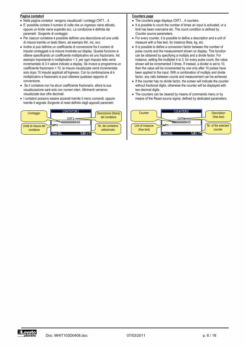
Pagina contatori � Nella pagina contatori vengono visualizzati i conteggi CNT1…4. � E’ possibile contare il numero di volte che un ingresso viene attivato,
oppure un limite viene superato ecc. La condizione è definita dai parametri Sorgente di conteggio.
� Per ciascun contatore è possibile definire una descrizione ed una unità di misura tramite un testo libero, ad esempio litri, mc, ecc.
� Inoltre si può definire un coefficiente di conversione fra il numero di impulsi conteggiati e la misura mostrata sul display. Questa funzione si ottiene specificando un coefficiente moltiplicativo ed uno frazionario. Ad esempio impostando k moltiplicativo = 3, per ogni impulso letto verrà incrementato di 3 il valore indicato a display. Se invece si programma un coefficiente frazionario = 10, la misura visualizzata verrà incrementata solo dopo 10 impulsi applicati all’ingresso. Con la combinazione di k moltiplicativo e frazionario si può ottenere qualsiasi rapporto di conversione.
� Se il contatore non ha alcun coefficiente frazionario, allora la sua visualizzazione sarà solo con numeri interi. Altrimenti verranno visualizzate due cifre decimali.
� I contatori possono essere azzerati tramite il menu comandi, oppure tramite il segnale Sorgente di reset definito dagli appositi parametri.
Counters page � The counters page displays CNT1…4 counters. � It is possible to count the number of times an input is activated, or a
limit has been overcame etc. The count condition is defined by Counter source parameters.
� For every counter, it is possible to define a description and a unit of measure with a free text, for instance litres, kg, etc.
� It is possible to define a conversion factor between the number of pulse counts and the measurement shown on display. This function can be obtained by specifying a multiply and a divide factor. For instance, setting the multiplier k to 3, for every pulse count, the value shown will be incremented 3 times. If instead, a divider is set to 10, then the value will be incremented by one only after 10 pulses have been applied to the input. With a combination of multiply and divide factor, any ratio between counts and measurement can be achieved.
� If the counter has no divide factor, the screen will indicate the counter without fractional digits, otherwise the counter will be displayed with two decimal digits.
� The counters can be cleared by means of commands menu or by means of the Reset source signal, defined by dedicated parameters.
Nr. del contatore selezionato
Descrizione (libera) del contatore
Unità di misura del contatore
Conteggio
Nr. of the selected counter
Description (free text)
Unit of measure (free text)
Counter
Doc: MHIT103D0408.doc 07/03/2011 p. 7 / 18
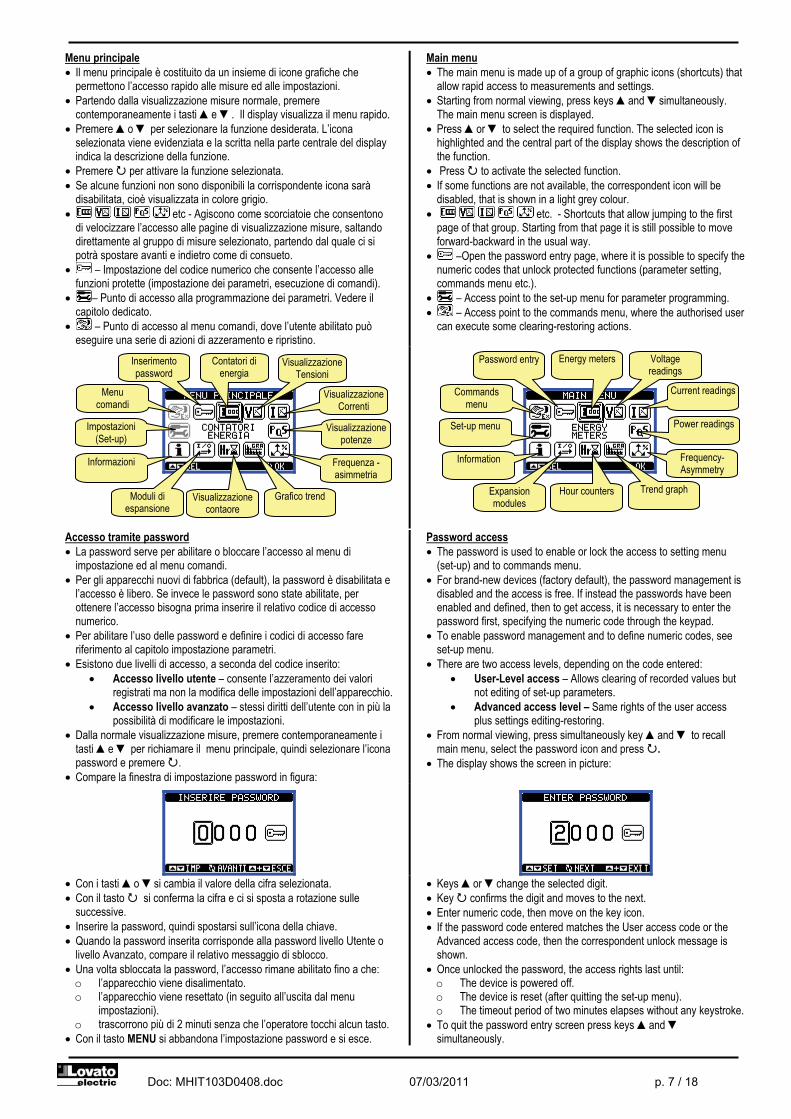
Menu principale � Il menu principale è costituito da un insieme di icone grafiche che
permettono l’accesso rapido alle misure ed alle impostazioni. � Partendo dalla visualizzazione misure normale, premere
contemporaneamente i tasti �e �. Il display visualizza il menu rapido. � Premere �o � per selezionare la funzione desiderata. L’icona
selezionata viene evidenziata e la scritta nella parte centrale del display indica la descrizione della funzione.
� Premere � per attivare la funzione selezionata. � Se alcune funzioni non sono disponibili la corrispondente icona sarà
disabilitata, cioè visualizzata in colore grigio. � etc - Agiscono come scorciatoie che consentono
di velocizzare l’accesso alle pagine di visualizzazione misure, saltando direttamente al gruppo di misure selezionato, partendo dal quale ci si potrà spostare avanti e indietro come di consueto.
� – Impostazione del codice numerico che consente l’accesso alle funzioni protette (impostazione dei parametri, esecuzione di comandi).
� – Punto di accesso alla programmazione dei parametri. Vedere il capitolo dedicato.
� – Punto di accesso al menu comandi, dove l’utente abilitato può eseguire una serie di azioni di azzeramento e ripristino.
Main menu � The main menu is made up of a group of graphic icons (shortcuts) that
allow rapid access to measurements and settings. � Starting from normal viewing, press keys �and �simultaneously.
The main menu screen is displayed. � Press �or � to select the required function. The selected icon is
highlighted and the central part of the display shows the description of the function.
� Press � to activate the selected function. � If some functions are not available, the correspondent icon will be
disabled, that is shown in a light grey colour. � etc. - Shortcuts that allow jumping to the first
page of that group. Starting from that page it is still possible to move forward-backward in the usual way.
� –Open the password entry page, where it is possible to specify the numeric codes that unlock protected functions (parameter setting, commands menu etc.).
� – Access point to the set-up menu for parameter programming. � – Access point to the commands menu, where the authorised user
can execute some clearing-restoring actions.
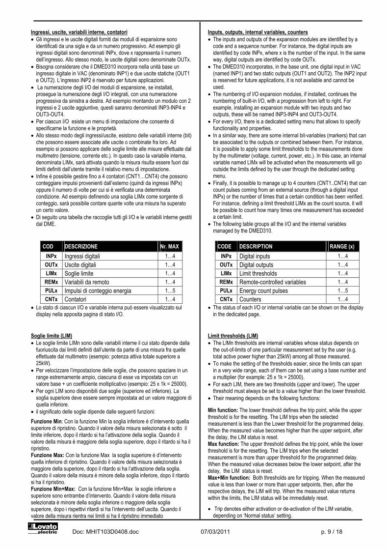
Accesso tramite password � La password serve per abilitare o bloccare l’accesso al menu di
impostazione ed al menu comandi. � Per gli apparecchi nuovi di fabbrica (default), la password è disabilitata e
l’accesso è libero. Se invece le password sono state abilitate, per ottenere l’accesso bisogna prima inserire il relativo codice di accesso numerico.
� Per abilitare l’uso delle password e definire i codici di accesso fare riferimento al capitolo impostazione parametri.
� Esistono due livelli di accesso, a seconda del codice inserito: � Accesso livello utente – consente l’azzeramento dei valori
registrati ma non la modifica delle impostazioni dell’apparecchio. � Accesso livello avanzato – stessi diritti dell’utente con in più la
possibilità di modificare le impostazioni. � Dalla normale visualizzazione misure, premere contemporaneamente i
tasti �e � per richiamare il menu principale, quindi selezionare l’icona password e premere �.
� Compare la finestra di impostazione password in figura:
Password access � The password is used to enable or lock the access to setting menu
(set-up) and to commands menu. � For brand-new devices (factory default), the password management is
disabled and the access is free. If instead the passwords have been enabled and defined, then to get access, it is necessary to enter the password first, specifying the numeric code through the keypad.
� To enable password management and to define numeric codes, see set-up menu.
� There are two access levels, depending on the code entered: � User-Level access – Allows clearing of recorded values but
not editing of set-up parameters. � Advanced access level – Same rights of the user access
plus settings editing-restoring. � From normal viewing, press simultaneously key �and � to recall
main menu, select the password icon and press �. � The display shows the screen in picture:
� Con i tasti �o �si cambia il valore della cifra selezionata. � Con il tasto � si conferma la cifra e ci si sposta a rotazione sulle
successive. � Inserire la password, quindi spostarsi sull’icona della chiave. � Quando la password inserita corrisponde alla password livello Utente o
livello Avanzato, compare il relativo messaggio di sblocco. � Una volta sbloccata la password, l’accesso rimane abilitato fino a che: o l’apparecchio viene disalimentato. o l’apparecchio viene resettato (in seguito all’uscita dal menu
impostazioni). o trascorrono più di 2 minuti senza che l’operatore tocchi alcun tasto.
� Con il tasto MENU si abbandona l’impostazione password e si esce.
� Keys �or �change the selected digit. � Key � confirms the digit and moves to the next. � Enter numeric code, then move on the key icon. � If the password code entered matches the User access code or the
Advanced access code, then the correspondent unlock message is shown.
� Once unlocked the password, the access rights last until: o The device is powered off. o The device is reset (after quitting the set-up menu). o The timeout period of two minutes elapses without any keystroke.
� To quit the password entry screen press keys �and � simultaneously.
Visualizzazione Correnti
Visualizzazione potenze
Frequenza -asimmetria
Grafico trend
Visualizzazione contaore
Moduli di espansione
Informazioni
Impostazioni (Set-up)
Menu comandi
Inserimento password
Contatori di energia
Visualizzazione Tensioni
Current readings
Power readings
Frequency-Asymmetry
Trend graph
Hour counters Expansion modules
Information
Set-up menu
Commands menu
Password entry Energy meters Voltage readings

Doc: MHIT103D0408.doc 07/03/2011 p. 8 / 18
Espandibilità � Grazie alla sua interfaccia ottica a raggi infrarossi incorporata, il
DMED310 può essere espanso con dei moduli aggiuntivi della serie EXM….
� Questi moduli sono a loro volta dotati di un’interfaccia ottica sul lato sinistro per il collegamento all’unità base e di una seconda sul lato destro per il collegamento di un ulteriore modulo di espansione.
� E’ possibile collegare ad un DMED310 un massimo di 3 moduli EXM…. � I moduli EXM… si dividono nelle seguenti categorie: o moduli di comunicazione o moduli di I/O digitale o moduli misti Comunicazione + uscite digitali o moduli di memoria
� I moduli si collegano alla unità base semplicemente affiancandoli e inserendo le apposite clip fino ad agganciarli a scatto.
� L’ordine di inserimento dei moduli è libero.
Expandability � Thanks to its built-in optical infrared interface, the DMED310 can be
expanded with EXM series modules. � These modules have an optical interface on the left side for the
connection to the base unit and a second interface on the right side for the connection of an additional expansion module.
� It is possible to connect a maximum of 3 EXM modules. � The EXM modules can be grouped in the following categories: o Communication modules o Digital I/O modules o Mixed modules – Communication + digital outputs o Memory modules.
The modules can be connected to the base unit simply placing them side by side and then inserting the dedicated clips. The insertion sequence is free.
� Quando un DMED310 viene alimentato, riconosce automaticamente i moduli EXM ad esso collegati.
� Se la configurazione del sistema è diversa rispetto all’ultima rilevata (è stato aggiunto o rimosso un modulo), l’unità base chiede all’utente di confermare la nuova configurazione. In caso di conferma la nuova configurazione verrà salvata e diventerà effettiva, altrimenti ad ogni messa in tensione verrà segnalata la discordanza.
� La configurazione attuale del sistema è visualizzata nella apposita pagina del display (moduli espansione), dove si vedono il numero, il tipo e lo stato dei moduli collegati.
� Gli I/O integrati sono visualizzati sotto il simbolo dell’unità base. � La numerazione degli I/O di espansione viene elencata sotto ogni
modulo. � Lo stato (attivato/disattivato) degli I/O e dei canali di comunicazione
viene evidenziato con la scritta in negativo.
� When a DMED310 is powered on, it automatically recognises the EXM modules that have been mounted.
� If the system configuration has changed with respect to the last saved, (one module has been added or removed), the base unit asks the user to confirm the new configuration. In case of confirmation, the new configuration will be saved and will become effective, otherwise the mismatch will be shown at every subsequent power-on of the multimeter.
� The actual system configuration is shown in the dedicated page of the display (expansion modules), where it is possible to see the number, the type and the status of the modules.
� The integrated I/O are shown under the symbol of the base unit. � The expansion I/O numbering is shown under each module. � The status (energised/de-energised) of every single I/O and
communication channel is highlighted in reverse
Risorse aggiuntive � I moduli di espansione forniscono delle risorse aggiuntive che possono
essere sfruttate tramite gli opportuni menu di impostazione. � I menu di impostazione che riguardano le espansioni sono disponibili
anche se i moduli non sono fisicamente presenti. � Dato che è possibile aggiungere più moduli della stessa tipologia (ad
esempio due interfacce di comunicazione) i relativi menu di impostazione sono multipli, identificati da un numero progressivo.
� Di seguito una tabella che indica quanti moduli di ogni tipo possono essere montati contemporaneamente. Il numero totale di moduli deve essere <= 3.
TIPO MODULO CODICE FUNZIONE Nr. MAX EXM 10 10 USB EXM 10 11 RS-232 EXM 10 12 RS-485
COMUNICAZIONE
EXM 10 13 ETHERNET
1
I/O DIGITALI EXM 10 00 2 IN + 2 SSR EXM 10 01 2 IN + 2 RELE’
1
MISTI EXM 10 20
485 + 2 RELE’ 1
Additional resources � The expansion modules provide additional resources that can be used
through the dedicated set-up menus. � The set-up menus related to the expansions are always accessible,
even if the expansion modules are not physically fitted. � Since it is possible to add more than one module of the same typology
(for instance two communication interfaces), the set-up menus are multiple, identified by a sequential number.
� The following table indicates how many modules of each group can be mounted at the same time. The total number of modules must be less or equal than 3.
MODULE TYPE CODE FUNCTION MAX No. EXM 10 10 USB EXM 10 11 RS-232 EXM 10 12 RS-485
COMMUNICATION
EXM 10 13 ETHERNET
1
DIGITAL I/O EXM 10 00 2 IN + 2 SSR EXM 10 01 2 IN + 2 RELAYS
1
MIXED EXM 10 20
485 + 2 RELAYS 1
Numerazione e stato della
espansione
Tipo dei moduli di espansione
I/O integrati
Unità base
Numbering and status of the expansion
Type of the expansion module
Built-in I/O
Base unit
Doc: MHIT103D0408.doc 07/03/2011 p. 9 / 18
Ingressi, uscite, variabili interne, contatori � Gli ingressi e le uscite digitali forniti dai moduli di espansione sono
identificati da una sigla e da un numero progressivo. Ad esempio gli ingressi digitali sono denominati INPx, dove x rappresenta il numero dell’ingresso. Allo stesso modo, le uscite digitali sono denominate OUTx.
� Bisogna considerare che il DMED310 incorpora nella unità base un ingresso digitale in VAC (denominato INP1) e due uscite statiche (OUT1 e OUT2). L’ingresso INP2 è riservato per future applicazioni.
� La numerazione degli I/O dei moduli di espansione, se installati, prosegue la numerazione degli I/O integrati, con una numerazione progressiva da sinistra a destra. Ad esempio montando un modulo con 2 ingressi e 2 uscite aggiuntive, questi saranno denominati INP3-INP4 e OUT3-OUT4.
� Per ciascun I/O esiste un menu di impostazione che consente di specificarne la funzione e le proprietà.
� Allo stesso modo degli ingressi/uscite, esistono delle variabili interne (bit) che possono essere associate alle uscite o combinate fra loro. Ad esempio si possono applicare delle soglie limite alle misure effettuate dal multimetro (tensione, corrente etc.). In questo caso la variabile interna, denominata LIMx, sarà attivata quando la misura risulta essere fuori dai limiti definiti dall’utente tramite il relativo menu di impostazione.
� Infine è possibile gestire fino a 4 contatori (CNT1…CNT4) che possono conteggiare impulsi provenienti dall’esterno (quindi da ingressi INPx) oppure il numero di volte per cui si è verificata una determinata condizione. Ad esempio definendo una soglia LIMx come sorgente di conteggio, sarà possibile contare quante volte una misura ha superato un certo valore.
� Di seguito una tabella che raccoglie tutti gli I/O e le variabili interne gestiti dal DME.
COD DESCRIZIONE Nr. MAX ( )INPx Ingressi digitali 1…4
OUTx Uscite digitali 1…4 LIMx Soglie limite 1…4 REMx Variabili da remoto 1…4 PULx Impulsi di conteggio energia 1…5 CNTx Contatori 1…4
� Lo stato di ciascun I/O e variabile interna può essere visualizzato sul display nella apposita pagina di stato I/O.
Inputs, outputs, internal variables, counters � The inputs and outputs of the expansion modules are identified by a
code and a sequence number. For instance, the digital inputs are identified by code INPx, where x is the number of the input. In the same way, digital outputs are identified by code OUTx.
� The DMED310 incorporates, in the base unit, one digital input in VAC (named INP1) and two static outputs (OUT1 and OUT2). The INP2 input is reserved for future applications, it is not available and cannot be used.
� The numbering of I/O expansion modules, if installed, continues the numbering of built-in I/O, with a progression from left to right. For example, installing an expansion module with two inputs and two outputs, these will be named INP3-INP4 and OUT3-OUT4.
� For every I/O, there is a dedicated setting menu that allows to specify functionality and properties.
� In a similar way, there are some internal bit-variables (markers) that can be associated to the outputs or combined between them. For instance, it is possible to apply some limit thresholds to the measurements done by the multimeter (voltage, current, power, etc.). In this case, an internal variable named LIMx will be activated when the measurements will go outside the limits defined by the user through the dedicated setting menu.
� Finally, it is possible to manage up to 4 counters (CNT1..CNT4) that can count pulses coming from an external source (through a digital input INPx) or the number of times that a certain condition has been verified. For instance, defining a limit threshold LIMx as the count source, it will be possible to count how many times one measurement has exceeded a certain limit.
� The following table groups all the I/O and the internal variables managed by the DMED310.
CODE DESCRIPTION RANGE (x)
INPx Digital inputs 1…4 OUTx Digital outputs 1…4 LIMx Limit thresholds 1…4 REMx Remote-controlled variables 1…4 PULx Energy count pulses 1…5 CNTx Counters 1…4
� The status of each I/O or internal variable can be shown on the display in the dedicated page.
Soglie limite (LIM) � Le soglie limite LIMn sono delle variabili interne il cui stato dipende dalla
fuoriuscita dai limiti definiti dall’utente da parte di una misura fra quelle effettuate dal multimetro (esempio: potenza attiva totale superiore a 25kW).
� Per velocizzare l’impostazione delle soglie, che possono spaziare in un range estremamente ampio, ciascuna di esse va impostata con un valore base + un coefficiente moltiplicativo (esempio: 25 x 1k = 25000).
� Per ogni LIM sono disponibili due soglie (superiore ed inferiore). La soglia superiore deve essere sempre impostata ad un valore maggiore di quella inferiore.
� il significato delle soglie dipende dalle seguenti funzioni:
Funzione Min: Con la funzione Min la soglia inferiore è d’intervento quella superiore di ripristino. Quando il valore della misura selezionata è sotto il limite inferiore, dopo il ritardo si ha l’attivazione della soglia. Quando il valore della misura è maggiore della soglia superiore, dopo il ritardo si ha il ripristino. Funzione Max: Con la funzione Max la soglia superiore è d’intervento quella inferiore di ripristino. Quando il valore della misura selezionata è maggiore della superiore, dopo il ritardo si ha l’attivazione della soglia. Quando il valore della misura è minore della soglia inferiore, dopo il ritardo si ha il ripristino. Funzione Min+Max: Con la funzione Min+Max le soglie inferiore e superiore sono entrambe d’intervento. Quando il valore della misura selezionata è minore della soglia inferiore o maggiore della soglia superiore, dopo i rispettivi ritardi si ha l’intervento dell’uscita. Quando il valore della misura rientra nei limiti si ha il ripristino immediato
Limit thresholds (LIM) � The LIMn thresholds are internal variables whose status depends on
the out-of-limits of one particular measurement set by the user (e.g. total active power higher than 25kW) among all those measured.
� To make the setting of the thresholds easier, since the limits can span in a very wide range, each of them can be set using a base number and a multiplier (for example: 25 x 1k = 25000).
� For each LIM, there are two thresholds (upper and lower). The upper threshold must always be set to a value higher than the lower threshold.
� Their meaning depends on the following functions: Min function: The lower threshold defines the trip point, while the upper threshold is for the resetting. The LIM trips when the selected measurement is less than the Lower threshold for the programmed delay. When the measured value becomes higher than the upper setpoint, after the delay, the LIM status is reset. Max function: The upper threshold defines the trip point, while the lower threshold is for the resetting. The LIM trips when the selected measurement is more than upper threshold for the programmed delay. When the measured value decreases below the lower setpoint, after the delay, the LIM status is reset. Max+Min function: Both thresholds are for tripping. When the measured value is less than lower or more than upper setpoints, then, after the respective delays, the LIM will trip. When the measured value returns within the limits, the LIM status will be immediately reset.
� Trip denotes either activation or de-activation of the LIM variable, depending on ‘Normal status’ setting.
Doc: MHIT103D0408.doc 07/03/2011 p. 10 / 18
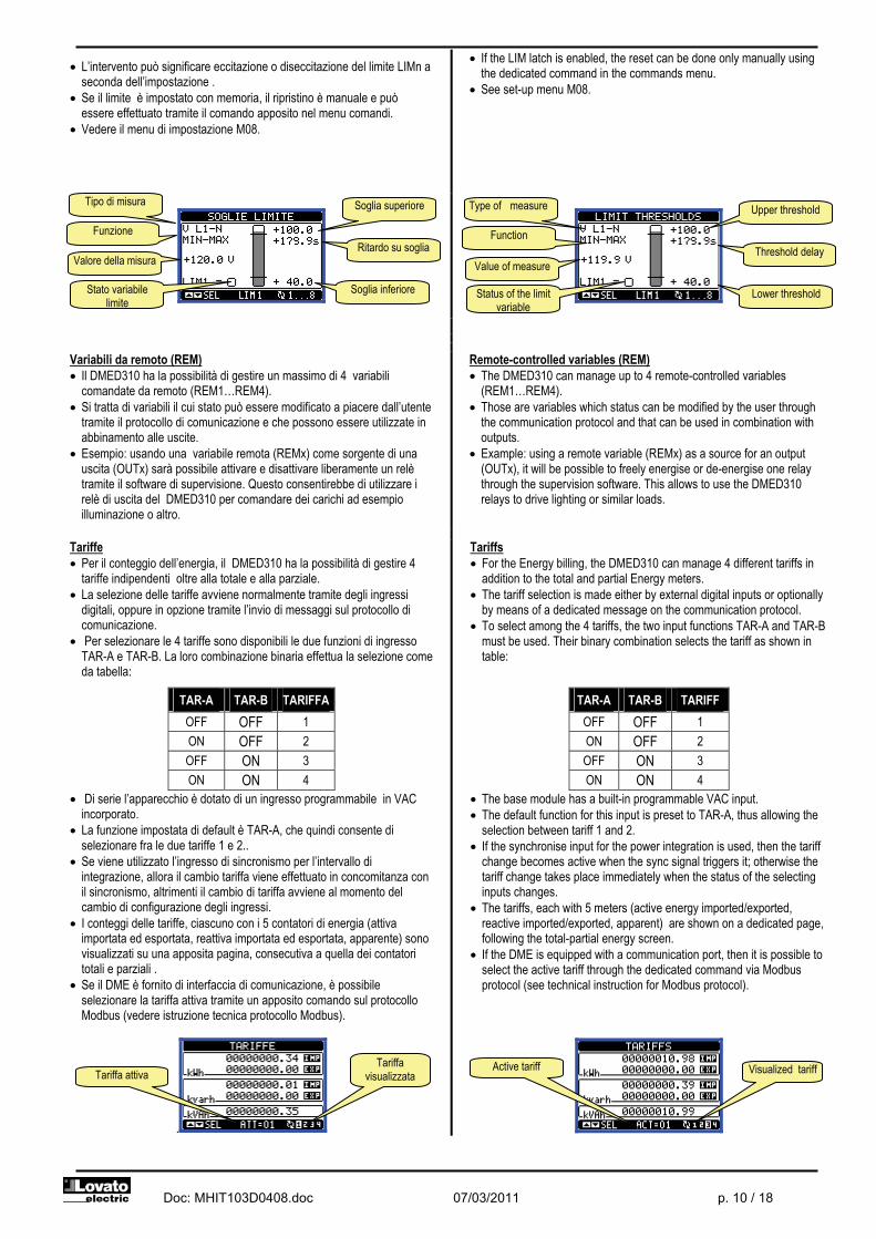
� L’intervento può significare eccitazione o diseccitazione del limite LIMn a seconda dell’impostazione .
� Se il limite è impostato con memoria, il ripristino è manuale e può essere effettuato tramite il comando apposito nel menu comandi.
� Vedere il menu di impostazione M08.
� If the LIM latch is enabled, the reset can be done only manually using the dedicated command in the commands menu.
� See set-up menu M08.
Variabili da remoto (REM) � Il DMED310 ha la possibilità di gestire un massimo di 4 variabili
comandate da remoto (REM1…REM4). � Si tratta di variabili il cui stato può essere modificato a piacere dall’utente
tramite il protocollo di comunicazione e che possono essere utilizzate in abbinamento alle uscite.
� Esempio: usando una variabile remota (REMx) come sorgente di una uscita (OUTx) sarà possibile attivare e disattivare liberamente un relè tramite il software di supervisione. Questo consentirebbe di utilizzare i relè di uscita del DMED310 per comandare dei carichi ad esempio illuminazione o altro.
Remote-controlled variables (REM) � The DMED310 can manage up to 4 remote-controlled variables
(REM1…REM4). � Those are variables which status can be modified by the user through
the communication protocol and that can be used in combination with outputs.
� Example: using a remote variable (REMx) as a source for an output (OUTx), it will be possible to freely energise or de-energise one relay through the supervision software. This allows to use the DMED310 relays to drive lighting or similar loads.
Tariffe � Per il conteggio dell’energia, il DMED310 ha la possibilità di gestire 4
tariffe indipendenti oltre alla totale e alla parziale. � La selezione delle tariffe avviene normalmente tramite degli ingressi
digitali, oppure in opzione tramite l’invio di messaggi sul protocollo di comunicazione.
� Per selezionare le 4 tariffe sono disponibili le due funzioni di ingresso TAR-A e TAR-B. La loro combinazione binaria effettua la selezione come da tabella:
TAR-A TAR-B TARIFFA OFF OFF 1 ON OFF 2 OFF ON 3 ON ON 4
� Di serie l’apparecchio è dotato di un ingresso programmabile in VAC incorporato.
� La funzione impostata di default è TAR-A, che quindi consente di selezionare fra le due tariffe 1 e 2..
� Se viene utilizzato l’ingresso di sincronismo per l’intervallo di integrazione, allora il cambio tariffa viene effettuato in concomitanza con il sincronismo, altrimenti il cambio di tariffa avviene al momento del cambio di configurazione degli ingressi.
� I conteggi delle tariffe, ciascuno con i 5 contatori di energia (attiva importata ed esportata, reattiva importata ed esportata, apparente) sono visualizzati su una apposita pagina, consecutiva a quella dei contatori totali e parziali .
� Se il DME è fornito di interfaccia di comunicazione, è possibile selezionare la tariffa attiva tramite un apposito comando sul protocollo Modbus (vedere istruzione tecnica protocollo Modbus).
.
Tariffs � For the Energy billing, the DMED310 can manage 4 different tariffs in
addition to the total and partial Energy meters. � The tariff selection is made either by external digital inputs or optionally
by means of a dedicated message on the communication protocol. � To select among the 4 tariffs, the two input functions TAR-A and TAR-B
must be used. Their binary combination selects the tariff as shown in table:
TAR-A TAR-B TARIFF OFF OFF 1 ON OFF 2 OFF ON 3 ON ON 4
� The base module has a built-in programmable VAC input. � The default function for this input is preset to TAR-A, thus allowing the
selection between tariff 1 and 2. � If the synchronise input for the power integration is used, then the tariff
change becomes active when the sync signal triggers it; otherwise the tariff change takes place immediately when the status of the selecting inputs changes.
� The tariffs, each with 5 meters (active energy imported/exported, reactive imported/exported, apparent) are shown on a dedicated page, following the total-partial energy screen.
� If the DME is equipped with a communication port, then it is possible to select the active tariff through the dedicated command via Modbus protocol (see technical instruction for Modbus protocol).
Tipo di misura
Funzione
Valore della misura
Soglia superiore
Ritardo su soglia
Soglia inferiore Stato variabile limite
Type of measure
Function
Value of measure
Upper threshold
Threshold delay
Lower threshold Status of the limit variable
Tariffa visualizzata Tariffa attiva
Active tariff Visualized tariff
Doc: MHIT103D0408.doc 07/03/2011 p. 11 / 18
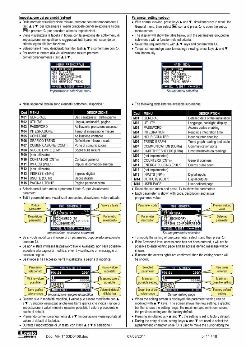
Impostazione dei parametri (set-up) � Dalla normale visualizzazione misure, premere contemporaneamente i
tasti �e � per richiamare il menu principale,quindi selezionare l’icona e premere � per accedere al menu impostazioni.
� Viene visualizzata la tabella in figura, con la selezione dei sotto-menu di impostazione, nei quali sono raggruppati tutti i parametri secondo un criterio legato alla loro funzione.
� Selezionare il menu desiderato tramite i tasti ��e confermare con �. � Per uscire e tornare alla visualizzazione misure premere
contemporaneamente i tasti �e �.
Impostazione: selezione menu
� Nella seguente tabella sono elencati i sottomenu disponibili :
Cod MENU DESCRIZIONE M01 GENERALE Dati caratteristici dell’impianto M02 UTILITA’ Lingua, luminosità, pagine M03 PASSWORD Abilitazione protezione accesso M04 INTEGRAZIONE Tempi di integrazione misure M05 CONTAORE Abilitazione contaore M06 GRAFICO TREND Definizione misura e scala M07 COMUNICAZIONE (COMn) Porte di comunicazione M08 SOGLIE LIMITE (LIMn) Soglie sulle misure M09 (non utilizzato) M10 CONTATORI (CNTn) Contatori generici M11 IMPULSI (PULn) Impulsi di conteggio energia M12 (non utilizzato) M13 INGRESSI (INPn) Ingressi digitali M14 USCITE (OUTn) Uscite digitali M15 PAGINA UTENTE Pagina personalizzata
Parameter setting (set-up) � With normal viewing, press keys �and � simultaneously to recall the
General menu, then select icon and press � to open the set-up menu screen.
� The display will show the table below, with the parameters grouped in sub-menus with a function-related criteria.
� Select the required menu with ��keys and confirm with �. � To quit set-up and go back to readings viewing, press keys �and �
simultaneously.
Set-up: menu selection
� The following table lists the available sub-menus:
Cod. MENU DESCRIPTION M01 GENERAL Detailed data of the installation M02 UTILITY Language, backlight, display M03 PASSWORD Access codes enabling M04 INTEGRATION Readings integration time M05 HOUR COUNTER Hour counter enabling M06 TREND GRAPH Trend graph reading and scale M07 COMMUNICATION (COMn) Communication ports M08 LIMIT THRESHOLDS (LIMn) Limit thresholds on readings M09 (not implemented) M10 COUNTERS (CNTn) General counters M11 ENERGY PULSING (PULn) Energy pulse count M12 (not implemented) M13 INPUTS (INPn) Digital inputs M14 OUTPUTS (OUTn) Digital outputs M15 USER PAGE User-defined page
� Selezionare il sotto-menu e premere il tasto � per visualizzare i parametri.
� Tutti i parametri sono visualizzati con codice, descrizione, valore attuale.
� Select the sub-menu and press � to show the parameters. � Each parameter is shown with code, description and actual
programmed value.
Impostazione: selezione parametri
Set-up: parameter selection
� Se si vuole modificare il valore di un parametro, dopo averlo selezionato premere �.
� Se non è stata immessa la password livello Avanzato, non sarà possibile accedere alla pagina di modifica, e verrà visualizzato un messaggio di accesso negato.
� Se invece si ha l’accesso, verrà visualizzata la pagina di modifica.
� To modify the setting of one parameter, select it and then press �. � If the Advanced level access code has not been entered, it will not be
possible to enter editing page and an access denied message will be shown.
� If instead the access rights are confirmed, then the editing screen will be shown.
Impostazione- pagina di modifica
Set-up: editing page
� Quando si è in modalità modifica, il valore può essere modificato con � e �. Vengono visualizzati anche una barra grafica che indica il range di impostazione, i valori minimi e massimi possibili, il valore precedente e quello di default.
� Premendo contemporaneamente �e �l’impostazione viene riportata al valore di default di fabbrica.
� Durante l’impostazione di un testo, con i tasti �e �si seleziona il
� When the editing screen is displayed, the parameter setting can be modified with ��keys. The screen shows the new setting, a graphic bar that shows the setting range, the maximum and minimum values, the previous setting and the factory default.
� Pressing simultaneously �and �, the setting is set to factory default. � During the entry of a text string, keys �and �are used to select the
alphanumeric character while � is used to move the cursor along the
Codice parametro
Descrizione parametro
Valore attuale
Parametro selezionato
Parameter code
Parameter description
Present setting value
Selected parameter
Parametro selezionato
Nuovo valore impostato
Valore di default di fabbrica
Minimo valore possibile
Barra grafica valore-range
Massimo valore possibile
Selected parameter
New value entered
Factory default setting
Minimum possible setting
Graph bar of the value-range
Maximum possible setting

Doc: MHIT103D0408.doc 07/03/2011 p. 12 / 18
carattere alfanumerico e con � si sposta il cursore all’interno del testo. Premendo contemporaneamente �e �la selezione alfanumerica si posiziona direttamente sul carattere ‘A’.
� Premere il tasto� per tornare alla selezione parametri. Il valore immesso rimane memorizzato.
� Premere contemporaneamente �e � per salvare i cambiamenti ed uscire dalla impostazione. Il multimetro esegue un reset e ritorna in funzionamento normale.
� Se non vengono premuti tasti per 2 minuti consecutivi, il menu set-up viene abbandonato automaticamente e il multimetro torna alla visualizzazione normale.
text string. Pressing keys �and �simultaneously will move the character selection straight to ‘A’.
� Press � to go back to the parameter selection. The entered value is stored.
� Press keys �and � simultaneously to save all the settings and to quit the set-up menu. The multimeter executes a reset and returns to normal operation.
� If the user does not press any key for more than 2 minutes, the multimeter leaves the set-up automatically and goes back to normal viewing.
Tabella parametri
Table of parameters
M01 – GENERALE UdM Default Range M01 – GENERAL UoM Default Range P01.01 Primario TA A 5 5-10000 P01.01 CT primary A 5 5-10000 P01.02 Secondario TA A 5 5 P01.02 CT secondary A 5 1-5 P01.03 Tensione nominale V AUT AUT /
220 – 415 P01.03 Nominal voltage V AUT AUT /
220 – 415 P01.04 Potenza nominale kW AUT AUT /
1 - 10000 P01.04 Nominal power kW AUT AUT /
1 - 10000 P01.05 Tipo di collegamento L1-L2-L3-N L1-L2-L3-N
L1-L2-L3 L1-N-L2
L1-N
P01.05 Wiring L1-L2-L3-N L1-L2-L3-N L1-L2-L3 L1-N-L2
L1-N P01.01 – Corrente nominale del primario dei TA. P01.02 – Corrente del secondario dei TA. Per DMED310 fissa a 5A. P01.05 – Impostare concordemente allo schema di collegamento utilizzato. Vedere Schemi di collegamento alla fine del manuale.
P01.01 – CT primary winding rated current. P01.02 – CT secondary winding rated current. For DMED310 fixed to 5A. P01.05 – Set this parameter according to the used wiring diagram. See wiring diagrams on last pages of the manual.
M02 – UTILITA’ UdM Default Range M02 – UTILITY UoM Default Range
P02.01 Lingua English English Italiano
Francais Espanol
Portuguese
P02.01 Language English English Italiano
Francais Espanol
Portuguese P02.02 Contrasto LCD % 50 0-100 P02.02 Display contrast % 50 0-100 P02.03 Intensità retroilluminazione
display alta % 100 0-100 P02.03 High backlight level % 100 0-100
P02.04 Intensità retroilluminazione display bassa
% 30 0-50 P02.04 Low backlight level % 30 0-50
P02.05 Tempo passaggio a retroilluminazione bassa
s 30 5-600 P02.05 Low backlight delay s 30 5-600
P02.06 Ritorno a pagina di default s 60 OFF / 10-600 P02.06 Default page return s 60 OFF / 10-600 P02.07 Pagina di default Energia-
potenza (lista pagine) P02.07 Default page Energy-
power (page list)
P02.08 Sotto-pagina di default IN / IMP / TOT
IN / IMP / TOT HI / EXP / PAR
LO AV MD GR 1- 4
P02.08 Default sub-page IN / IMP / TOT
IN / IMP / TOT HI / EXP / PAR
LO AV MD GR 1- 4
P02.09 Tempo di aggiornamento display
s 0.5 0.1 – 5.0
P02.09 Display update time s 0.5 0.1 – 5.0
P02.10 Comandi rapidi OFF C01-C02-C03-C04-C05-C06-C08
P02.10 Shortcut command OFF C01-C02-C03-C04-C05-C06-C08
P02.06 – Se impostato ad OFF il display rimane sempre nella pagina dove è stato lasciato dall’utente. Se impostato ad un valore, dopo questo tempo il display ritorna alla pagina impostata con P02.07. P02.07 – Numero della pagina alla quale il display ritorna automaticamente una volta che è trascorso il tempo P02.06 dall’ultima pressione di un tasto. P02.08 – Tipo di sotto-pagina alla quale il display torna dopo trascorso P02.06. P02.10 – Permette di eseguire un commando premendo per 5s il tasto �. Fare riferimento al paragrafo MENU COMANDI.
P02.06 – If set to OFF the display always remains in the page where the user left it. If set to a time delay, after that time the display page goes back to page set in P02.07. P02.07 – Number of the page to which the display returns automatically after time specified by P02.06 has elapsed from the last keystroke. P02.08 – Sub-page type to which the display returns after P02.06 has elapsed. P02.10 – Allows you to execute a command by pressing key � for 5 seconds. Refer to COMMANDS MENU section.
M03 – PASSWORD UdM Default Range M03 – PASSWORD UoM Default Range
P03.01 Utilizzo password OFF OFF-ON P03.01 Enable passwords OFF OFF-ON P03.02 Password livello Utente 1000 0-9999 P03.02 User level password 1000 0-9999 P03.03 Password livello Avanzato 2000 0-9999 P03.03 Advanced level password 2000 0-9999
P03.01 – Se impostato ad OFF, la gestione delle password è disabilitata e l’accesso alle impostazioni e al menu comandi è libero. P03.02 – Con P03.01 attivo, valore da specificare per attivare l’accesso a livello utente. Vedere capitolo Accesso tramite password. P03.03 – Come P03.02, riferito all’accesso livello Avanzato.
P03.01 – If set to OFF, password management is disabled and the access to set-up parameters and commands menu is allowed. P03.02 – When P.03.01 enabled, value to be specified to get user access. P03.03 – Like P03.02, but referred to advanced access.

Doc: MHIT103D0408.doc 07/03/2011 p. 13 / 18
M04 – INTEGRAZIONE UdM Default Range M04 – INTEGRATION UoM Default Range P04.01 Modo integrazione Scorr. Fisso
Scorrevole Sincronismo
Bus
P04.01 Integration mode Shift Fixed Shift Sync Bus
P04.02 Tempo integrazione potenze min 15 1-60min P04.02 Power integration time min 15 1-60min P04.03 Tempo integrazione correnti min 15 1-60min P04.03 Current integration time min 15 1-60min P04.04 Tempo di integrazione
tensioni min 1 1-60min P04.04 Voltage integration time min 1 1-60min
P04.05 Tempo di integrazione frequenza
min 1 1-60min P04.05 Frequency integration time
min 1 1-60min
P04.01 – Selezione della modalità di calcolo delle misure integrate. Fisso = Le misure istantanee vengono integrate per il tempo impostato. Ad ogni scadenza del tempo, la misura integrata viene aggiornata con il risultato dell’ultima integrazione. Scorrevole = Le misure istantanee vengono integrate per un tempo = 1/15 del tempo impostato. Ad ogni scadenza di questo intervallo viene sostituito il valore più vecchio con il nuovo calcolato. La misura integrata viene aggiornata ogni 1/15 del tempo impostato, considerando una finestra scorrevole nel tempo che comprende gli ultimi 15 valori calcolati, di lunghezza totale equivalente al tempo impostato. Sincronismo = Come modalità fisso, ma gli intervalli di integrazione sono scanditi da un ingresso digitale esterno programmato con la funzione sincronismo. Bus = Come modalità fisso, ma gli intervalli di integrazione sono scanditi da messaggi di sincronismo inviati sul bus seriale. P04.02 - Tempo integrazione misure AVG (media) per le potenze attiva, reattiva ed apparente. P04.03, P04.04, P04.05 - Tempo integrazione misure AVG (media) per le relative grandezze.
P04.01 – Selection of average reading calculation method: Fixed = Readings are integrated for the set time. Every time the integration time elapses, the Average value is updated with the result of the last integration. Shift = The instantaneous values are integrated for a period f time equal to 1/15th of the set time. Every time this interval elapses, the oldest value is replaced with the new one just calculated. The average value is updated every 1/15th of the time set, considering a time-sliding window that groups the last 15 calculated values, with a total length equal to integration time setting. Sync = Like fixed mode, but the integration intervals are started by an external digital input programmed with Synchronization function. Bus = Like fixed mode, but the integration intervals are started by communication messages on the serial bus. P04.02 - Average readings integration time, used for active, reactive and apparent power. P04.03, P04.04, P04.05 - Readings integration time (AVG) for the correspondent measurements.
M05 – CONTAORE UdM Default Range M05 – HOUR COUNTER UoM Default Range P05.01 Abilitazione generale
contaore ON OFF-ON P05.01 Hour counters enable ON OFF-ON
P05.02 Abilitazione contaore parziale
ON OFF-ON- INPx- LIMx P05.02 Partial hour counter enable
ON OFF-ON- INPx-LIMx
P05.03 Numero canale (x) 1 1 - 4 P05.03 Channel number (x) 1 1 - 4 P05.01 - Se OFF i contaore sono disabilitati e la pagina di misura dei contaore non viene visualizzata. P05.02 - Se OFF il contaore parziale non viene incrementato. Se ON viene incrementato quando il multimetro è alimentato. Se abbinato ad una delle variabili interne (LIMn-INPx) viene incrementato solo quando questa condizione è vera. P05.03 - Numero del canale (x) della variabile interna eventualmente usato nel parametro precedente. Esempio: Se il contaore parziale deve contare il tempo per cui una misura è oltre una certa soglia, definita dal limite LIM3, programmare LIMx nel parametro precedente e specificare 3 in questo parametro.
P05.01 - If set to OFF the hour counters are disabled and the hour meter page is not shown. P05.02 - If set to OFF, the partial hour counter is not incremented. If ON, time is incremented as long as DME is powered. P05.03 - Number of the channel (x) of the variable eventually used in the previous parameter. Example: If the partial hour counter must count the time during which one measurement is above a certain threshold, defined by LIM3, then program LIMx in the previous parameter and channel 3 in this parameter.
M06 – GRAFICO TREND UdM Default Range M06 –TREND GRAPH UoM Default Range
P06.01 Misura per pagina trend kW (tot) AVG
VL-L (eq) AVG kW (tot) AVG kvar (tot) AVG kVA (tot) AVG
P06.01 Trend graph measure kW (tot) AVG
VL-L (eq) AVG kW (tot) AVG kvar (tot) AVG kVA(tot) AVG
P06.02 Autorange scala ON OFF-ON P06.02 Autorange ON OFF-ON P06.03 Valore fondo scala 1000 0-1000 P06.03 Full scale value 1000 0-1000 P06.04 Moltiplicatore fondo scala x1 x1 – x1k – x1M P06.04 Full scale multiplier x1 x1 – x1k – x1M
P06.01 – Seleziona la misura da visualizzare sul grafico Trend. P06.02 – Decide se la scala verticale si adatta automaticamente ai valori visualizzati oppure se viene definita fissa dall’utente. P06.03 – Valore di fondo scala definito dall’utente. L’unità di misura diventa quella della misura selezionata. P06.04 – Moltiplicatore del valore di fondo scala.
P06.01 – Selects the reading to be shown on trend graph page. P06.02 – Choice between automatic range or fixed range defined by the user. P06.03 – Full scale range value. The unit of measure is the one defined by the selected reading. P06.04 – Full scale value multiplier.
M07 – COMUNICAZIONE (COMn, n=1)
UdM Default Range
M07 – COMMUNICATION (COMn, n=1)
UoM Default Range
P07.n.01 Indirizzo seriale nodo 01 01-255 P07.n.01 Serial node address 01 01-255 P07.n.02 Velocità seriale
bps 9600 1200
2400 4800 9600 19200 38400
P07.n.02 Serial speed bps 9600 1200 2400 4800 9600
19200 38400
P07.n.03 Formato dati 8 bit – n 8 bit, no parità 8 bit, dispari
8bit, pari 7 bit, dispari
7 bit, pari
P07.n.03 Data format 8 bit – n 8 bit, no parity 8 bit, odd 8bit, even 7 bit, odd 7 bit, even
P07.n.04 Bit di stop 1 1-2 P07.n.04 Stop bits 1 1-2 P07.n.05 Protocollo Modbus
RTU Modbus RTU Modbus ASCII
P07.n.05 Protocol Modbus RTU
Modbus RTU Modbus ASCII
P07.n.06 Indirizzo IP 000.000.000.000
000.000.000.000 - 255.255.255.255
P07.n.06 IP Address 000.000. 000.000
000.000.000.000 - 255.255.255.255
P07.n.07 Subnet mask 000.000.000.000
000.000.000.000 - 255.255.255.255
P07.n.07 Subnet mask 000.000. 000.000
000.000.000.000 - 255.255.255.255
P07.n.08 Porta IP 1001 0-9999
P07.n.08 IP port 1001 0-9999
Doc: MHIT103D0408.doc 07/03/2011 p. 14 / 18
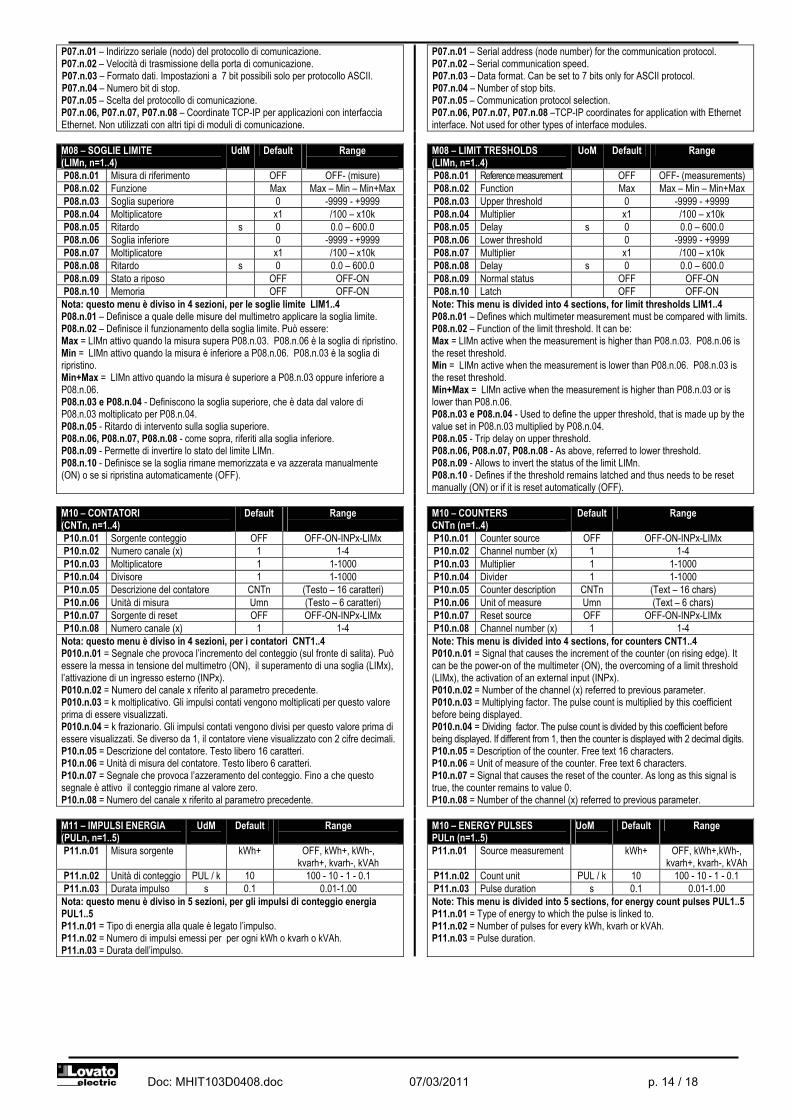
P07.n.01 – Indirizzo seriale (nodo) del protocollo di comunicazione. P07.n.02 – Velocità di trasmissione della porta di comunicazione. P07.n.03 – Formato dati. Impostazioni a 7 bit possibili solo per protocollo ASCII. P07.n.04 – Numero bit di stop. P07.n.05 – Scelta del protocollo di comunicazione. P07.n.06, P07.n.07, P07.n.08 – Coordinate TCP-IP per applicazioni con interfaccia Ethernet. Non utilizzati con altri tipi di moduli di comunicazione.
P07.n.01 – Serial address (node number) for the communication protocol. P07.n.02 – Serial communication speed. P07.n.03 – Data format. Can be set to 7 bits only for ASCII protocol. P07.n.04 – Number of stop bits. P07.n.05 – Communication protocol selection. P07.n.06, P07.n.07, P07.n.08 –TCP-IP coordinates for application with Ethernet interface. Not used for other types of interface modules.
M08 – SOGLIE LIMITE (LIMn, n=1..4)
UdM Default Range
M08 – LIMIT TRESHOLDS (LIMn, n=1..4)
UoM Default Range
P08.n.01 Misura di riferimento OFF OFF- (misure)
P08.n.01 Reference measurement OFF OFF- (measurements) P08.n.02 Funzione Max Max – Min – Min+Max P08.n.02 Function Max Max – Min – Min+Max P08.n.03 Soglia superiore 0 -9999 - +9999 P08.n.03 Upper threshold 0 -9999 - +9999 P08.n.04 Moltiplicatore x1 /100 – x10k P08.n.04 Multiplier x1 /100 – x10k P08.n.05 Ritardo s 0 0.0 – 600.0 P08.n.05 Delay s 0 0.0 – 600.0 P08.n.06 Soglia inferiore 0 -9999 - +9999 P08.n.06 Lower threshold 0 -9999 - +9999 P08.n.07 Moltiplicatore x1 /100 – x10k P08.n.07 Multiplier x1 /100 – x10k P08.n.08 Ritardo s 0 0.0 – 600.0 P08.n.08 Delay s 0 0.0 – 600.0 P08.n.09 Stato a riposo OFF OFF-ON P08.n.09 Normal status OFF OFF-ON P08.n.10 Memoria OFF OFF-ON P08.n.10 Latch OFF OFF-ON Nota: questo menu è diviso in 4 sezioni, per le soglie limite LIM1..4 P08.n.01 – Definisce a quale delle misure del multimetro applicare la soglia limite. P08.n.02 – Definisce il funzionamento della soglia limite. Può essere: Max = LIMn attivo quando la misura supera P08.n.03. P08.n.06 è la soglia di ripristino. Min = LIMn attivo quando la misura è inferiore a P08.n.06. P08.n.03 è la soglia di ripristino. Min+Max = LIMn attivo quando la misura è superiore a P08.n.03 oppure inferiore a P08.n.06. P08.n.03 e P08.n.04 - Definiscono la soglia superiore, che è data dal valore di P08.n.03 moltiplicato per P08.n.04. P08.n.05 - Ritardo di intervento sulla soglia superiore. P08.n.06, P08.n.07, P08.n.08 - come sopra, riferiti alla soglia inferiore. P08.n.09 - Permette di invertire lo stato del limite LIMn. P08.n.10 - Definisce se la soglia rimane memorizzata e va azzerata manualmente (ON) o se si ripristina automaticamente (OFF).
Note: This menu is divided into 4 sections, for limit thresholds LIM1..4 P08.n.01 – Defines which multimeter measurement must be compared with limits. P08.n.02 – Function of the limit threshold. It can be: Max = LIMn active when the measurement is higher than P08.n.03. P08.n.06 is the reset threshold. Min = LIMn active when the measurement is lower than P08.n.06. P08.n.03 is the reset threshold. Min+Max = LIMn active when the measurement is higher than P08.n.03 or is lower than P08.n.06. P08.n.03 e P08.n.04 - Used to define the upper threshold, that is made up by the value set in P08.n.03 multiplied by P08.n.04. P08.n.05 - Trip delay on upper threshold. P08.n.06, P08.n.07, P08.n.08 - As above, referred to lower threshold. P08.n.09 - Allows to invert the status of the limit LIMn. P08.n.10 - Defines if the threshold remains latched and thus needs to be reset manually (ON) or if it is reset automatically (OFF).
M10 – CONTATORI (CNTn, n=1..4)
Default Range
M10 – COUNTERS CNTn (n=1..4)
Default Range
P10.n.01 Sorgente conteggio OFF OFF-ON-INPx-LIMx
P10.n.01 Counter source OFF OFF-ON-INPx-LIMx P10.n.02 Numero canale (x) 1 1-4 P10.n.02 Channel number (x) 1 1-4 P10.n.03 Moltiplicatore 1 1-1000 P10.n.03 Multiplier 1 1-1000 P10.n.04 Divisore 1 1-1000 P10.n.04 Divider 1 1-1000 P10.n.05 Descrizione del contatore CNTn (Testo – 16 caratteri) P10.n.05 Counter description CNTn (Text – 16 chars) P10.n.06 Unità di misura Umn (Testo – 6 caratteri) P10.n.06 Unit of measure Umn (Text – 6 chars) P10.n.07 Sorgente di reset OFF OFF-ON-INPx-LIMx P10.n.07 Reset source OFF OFF-ON-INPx-LIMx P10.n.08 Numero canale (x) 1 1-4 P10.n.08 Channel number (x) 1 1-4 Nota: questo menu è diviso in 4 sezioni, per i contatori CNT1..4 P010.n.01 = Segnale che provoca l’incremento del conteggio (sul fronte di salita). Può essere la messa in tensione del multimetro (ON), il superamento di una soglia (LIMx), l’attivazione di un ingresso esterno (INPx). P010.n.02 = Numero del canale x riferito al parametro precedente. P010.n.03 = k moltiplicativo. Gli impulsi contati vengono moltiplicati per questo valore prima di essere visualizzati. P010.n.04 = k frazionario. Gli impulsi contati vengono divisi per questo valore prima di essere visualizzati. Se diverso da 1, il contatore viene visualizzato con 2 cifre decimali. P10.n.05 = Descrizione del contatore. Testo libero 16 caratteri. P10.n.06 = Unità di misura del contatore. Testo libero 6 caratteri. P10.n.07 = Segnale che provoca l’azzeramento del conteggio. Fino a che questo segnale è attivo il conteggio rimane al valore zero. P10.n.08 = Numero del canale x riferito al parametro precedente.
Note: This menu is divided into 4 sections, for counters CNT1..4 P010.n.01 = Signal that causes the increment of the counter (on rising edge). It can be the power-on of the multimeter (ON), the overcoming of a limit threshold (LIMx), the activation of an external input (INPx). P010.n.02 = Number of the channel (x) referred to previous parameter. P010.n.03 = Multiplying factor. The pulse count is multiplied by this coefficient before being displayed. P010.n.04 = Dividing factor. The pulse count is divided by this coefficient before being displayed. If different from 1, then the counter is displayed with 2 decimal digits. P10.n.05 = Description of the counter. Free text 16 characters. P10.n.06 = Unit of measure of the counter. Free text 6 characters. P10.n.07 = Signal that causes the reset of the counter. As long as this signal is true, the counter remains to value 0. P10.n.08 = Number of the channel (x) referred to previous parameter.
M11 – IMPULSI ENERGIA (PULn, n=1..5)
UdM
Default Range
M10 – ENERGY PULSES PULn (n=1..5)
UoM
Default Range
P11.n.01 Misura sorgente
kWh+ OFF, kWh+, kWh-, kvarh+, kvarh-, kVAh
P11.n.01 Source measurement
kWh+ OFF, kWh+,kWh-, kvarh+, kvarh-, kVAh
P11.n.02 Unità di conteggio PUL / k 10 100 - 10 - 1 - 0.1 P11.n.02 Count unit PUL / k 10 100 - 10 - 1 - 0.1 P11.n.03 Durata impulso s 0.1 0.01-1.00 P11.n.03 Pulse duration s 0.1 0.01-1.00 Nota: questo menu è diviso in 5 sezioni, per gli impulsi di conteggio energia PUL1..5 P11.n.01 = Tipo di energia alla quale è legato l’impulso. P11.n.02 = Numero di impulsi emessi per per ogni kWh o kvarh o kVAh. P11.n.03 = Durata dell’impulso.
Note: This menu is divided into 5 sections, for energy count pulses PUL1..5 P11.n.01 = Type of energy to which the pulse is linked to. P11.n.02 = Number of pulses for every kWh, kvarh or kVAh. P11.n.03 = Pulse duration.
Doc: MHIT103D0408.doc 07/03/2011 p. 15 / 18
M13 – INGRESSI (INPn, n=1..4)
UdM Default Range
M13 – INPUTS (INPn, n=1..4)
UoM Default Range
TAR-A (n=1)
TAR-A (n=1)
P13.n.01 Funzione ingresso
OFF (n=2...4)
OFF – ON – LOCK – SYNC – TAR-A –
TAR-B – C01-C02-C03-C04-C05-C06-C08
P13.n.01 Input function
OFF (n=2…4)
OFF – ON – LOCK – SYNC – TAR-A –
TAR-B – C01-C02-C03-C04-C05-C06-
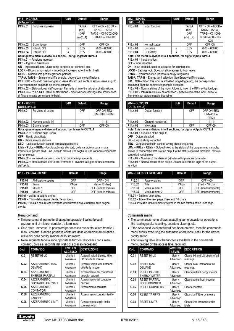
C08 P13.n.02 Stato riposo OFF OFF-ON P13.n.02 Normal status OFF OFF-ON P13.n.03 Ritardo ON s 0.05 0.00 – 600.00 P13.n.03 On delay s 0.05 0.00 – 600.00 P13.n.04 Ritardo OFF s 0.05 0.00 – 600.00 P13.n.04 OFF delay s 0.05 0.00 – 600.00 Nota: questo menu è diviso in 4 sezioni, per gli ingressi INP1..4 P13.n.01 = Funzione ingresso: OFF – Ingresso disabilitato ON – Ingresso abilitato, usato come sorgente per contatori ecc. LOCK – Blocco impostazioni – impedisce l’accesso ad entrambi i livelli. SYNC – Sincronismo per integrazione potenza. TAR-A, TAR-B – Selezione tariffa energie. Vedere capitolo tariffazione. C01…C08 – Quando questo ingresso viene attivato (sul fronte di salita), viene esguito il corrispondente comando del menu comandi. P13.n.02 = Stato a riposo dell’ingresso. Permette di invertire la logica di attivazione. P13.n.03 – P13.n.04 = Ritardi di attivazione – disattivazione dell’ingresso. Permettono di filtrare lo stato per evitare rimbalzi.
Note: This menu is divided into 4 sections, for digital inputs INP1..4 P13.n.01 = Input function: OFF – Input disabled ON – Input enabled, used as a source for counters etc. LOCK – Settings lock. Does not allow access to both levels. SYNC – Synchronisation for power/energy integration. TAR-A, TAR-B – Energy tariff selection. See Energy tariffs chapter. C01…C08 – When this input is activated (edge-triggered), the correspondent command from the commands menu is executed. P13.n.02 = Normal status of the input. Allows to invert the INPn activation logic. P13.n.03 – P13.n.04 = Delay on activation – deactivation of the input. Allow to filter the input status to avoid bouncing.
M14 – USCITE (OUTn, n=1..4)
UdM Default Range
M14 – OUTPUTS (OUTn, n=1..8)
UoM Default Range
P14.n.01 Funzione di uscita OFF OFF-ON-SEQ- LIMx-PULx-REMx
P14.n.01 Output function OFF OFF-ON-SEQ-LIMx-PULx-
REMx P14.n.02 Numero canale (x) 1 1 – 4 P14.n.02 Channel number (x) 1 1 – 4 P14.n.03 Stato a riposo OFF OFF-ON P14.n.03 Idle status OFF OFF-ON Nota: questo menu è diviso in 4 sezioni, per le uscite OUT1..4 P14.n.01 = Funzione della uscita: OFF – Uscita disabilitata ON – Uscita sempre abilitata SEQ – Uscita attivata in caso di errata sequenza fasi LIMx – PULx – REMx – Uscita abbinata allo stato della variabile programmata. Permette di portare su di una uscita lo stato di una soglia, di una variabile comandata da remoto ecc. P14.n.02 = Numero di canale (x) riferito al parametro precedente. P14.n.03 = Stato a riposo dell’uscita. Permette di invertire la logica di funzionamento dell’uscita.
Note: This menu is divided into 4 sections, for digital outputs OUT1..4 P14.n.01 = Function of the output: OFF – Output disabled ON – Output always enabled SEQ – Output enabled in case of wrong phase sequence LIMx – PULx – REMx – Output linked to the status of the programmed variable. Allows to connect the status of an output to the status of a limit threshold, remote-controlled variable etc. P14.n.02 = Number of the channel (x) referred to previous parameter. P14.n.03 = Normal status of the output. Allows to invert the logic of the output function.
M15 – PAGINA UTENTE
Default Range
M15 – USER-DEFINED PAGE
Default Range
P15.01 Abilitazione pagina OFF OFF – ON
P15.01 Page enabling OFF OFF – ON P15.02 Titolo PAGn (testo 16 char) P15.02 Title PAGn (Text – 16 char) P15.03 Misura 1 OFF OFF-(tutte le misure) P15.03 Measurement 1 OFF OFF- (measurements) P15.04 Misura 2 OFF OFF-(tutte le misure) P15.04 Measurement 2 OFF OFF- (measurements)
P15.01 = Abilita la pagina utente. P15.02 = Titolo della pagina utente. Testo libero. P15.03, P15.04,= Misure che verranno visualizzate nei due riquadri della pagina utente.
P15.01 = Enables user page. P15.02 = Title of the user page. Free text, 16 chars. P15.03, P15.04= Measurements viewed in the two frames of the user page.
Menu comandi � Il menu comandi permette di eseguire operazioni saltuarie quali
azzeramenti di misure, contatori, allarmi ecc. � Se è stata immessa la password per accesso avanzato, allora tramite il
menu comandi è anche possibile effettuare delle operazioni automatiche utili ai fini della configurazione dello strumento.
� Nella seguente tabella sono riportate le funzioni disponibili con il menu comandi, divise a seconda del livello di accesso necessario.
Cod. COMANDO LIVELLO ACCESSO
DESCRIZIONE
C.01 RESET HI-LO Utente / Avanzato
Azzera i valori di picco HI e LO di tutte le misure
C.02 AZZERAMENTO MAX DEMAND
Utente / Avanzato
Azzera i valori Max demand di tutte le misure
C.03 AZZERAMENTO ENERGIE PARZIALI
Utente / Avanzato
Azzeramento dei contatori di energia parziali.
C.04 AZZERAMENTO CONTAORE PARZIALI
Utente / Avanzato
Azzeramento dei contaore parziali
C.05 AZZERAMENTO CONTATORI
Utente / Avanzato
Azzeramento contatori
C.06 AZZERAMENTO TARIFFE
Utente / Avanzato
Azzeramento contatori tariffe
C.08 AZZERAMENTO LIMITI Utente / Avanzato
Azzeramento soglie limite con memoria
Commands menu � The commands menu allows executing some occasional operations
like reading peaks resetting, counters clearing, etc. � If the Advanced level password has been entered, then the commands
menu allows executing the automatic operations useful for the device configuration.
� The following table lists the functions available in the commands menu, divided by the access level required.
Cod. COMMAND ACCESS LEVEL
DESCRIPTION
C.01 RESET HI-LO User / Advanced
Clears HI and LO peaks of all readings.
C.02 RESET MAX DEMAND
User / Advanced
Clears Max Demand of all readings.
C.03 RESET PARTIAL ENERGY METER
User / Advanced
Clears partial Energy meters.
C.04 RESET PARTIAL HOUR COUNTER
User / Advanced
Clears partial hour counter.
C.05 RESET COUNTERS User / Advanced
Clears counters
C.06 RESET TARIFFS User / Advanced
Clears tariff Energy meters
C.08 RESET LIMITS User / Advanced
Clears limit thresholds with latch

Doc: MHIT103D0408.doc 07/03/2011 p. 16 / 18
C.12 AZZERAMENTO
CONTAORE TOTALE Avanzato Azzeramento del contaore
totale C.13 PARAMETRI A
DEFAULT Avanzato Ripristina tutte le
impostazioni ai valori di default di fabbrica
C.14 BACKUP PARAMETRI Avanzato Salva una copia di sicurezza (backup) delle impostazioni
C.15 RIPRISTINO PARAMETRI
Avanzato Ricarica le impostazioni dalla copia di sicurezza
C.16 TEST COLLEGAMENTO Avanzato Esegue il test per verificare la correttezza del collegamento del DME. Vedere capitolo Test collegamento.
� Una volta selezionato il comando desiderato, premere � per eseguirlo. Lo strumento chiederà una conferma. Premendo nuovamente � il comando verrà eseguito.
� Per annullare l’esecuzione di un comando selezionato premere contemporaneamente i tasti �e �.
� Per abbandonare il menu comandi premere contemporaneamente i tasti �e �.
C.12 RESET TOTAL HOUR
COUNTER Advanced Clears total hour counter.
C.13 PARAMETERS TO DEFAULT
Advanced All set-up parameters are reset to factory default value
C.14 PARAMETERS BACKUP
Advanced Saves a backup copy of all set-up parameters.
C.15 PARAMETERS RESTORE
Advanced Restores the set-up parameters to backup values.
C.16 WIRING TEST Advanced Carries out the wiring test in order to check proper wiring of the DME. See wiring test chapter.
� Once the required command has been selected, press � to execute it. The device will prompt for a confirmation. Pressing � again, the command will be executed.
� To cancel the command execution, press keys �and � simultaneously.
� To quit commands menu press key �and � simultaneously.
Test di collegamento � Il test di collegamento consente di verificare se l’installazione del
multimetro è stata effettuata correttamente. � Per poter eseguire il test, il multimetro deve essere inserito in un impianto
attivo con le seguenti condizioni: o sistema trifase con presenza di tutte le fasi (V > 50VAC L-N) o corrente minima circolante su ciascuna fase> 1% del fondo scala del
TA impostato o verso positivo delle energie (cioè in un comune impianto dove il
carico induttivo assorbe energia dalla fornitura) � Per lanciare l’esecuzione del test, entrare nel menu comandi e selezionare
il comando appropriato secondo le istruzioni del capitolo Menu comandi. � Il test consente di verificare i seguenti punti: o lettura delle tre tensioni o sequenza delle fasi o sbilanciamento delle tensioni o inversione della polarità di uno o più TA o scambio delle fasi fra tensioni/correnti
� Se il test non viene superato, il display visualizza la ragione dell’errore. � Se il test viene superato, la condizione viene memorizzata nella memoria
non volatile ed un messaggio che attesta l’esito positivo viene visualizzato nella pagina informazioni.
Wiring test � The wiring test allows to verify if the connection of the DME device
has been executed properly. � To be able to execute the test, the device must be connected to an
active plant, with the following conditions: o Three-phase system with all phases presence (V > 50VAC L-N) o Current flowing in each phase > 1% of the CT primary. o Positive flow of energies (that is a normal plant where the
inductive load draws power from the supplier). � To launch test execution, enter commands menu and select the
required command per commands menu instructions. � The test allows to verify the following points: o Reading of the three phases o Phase sequence o Voltage imbalance o Reverse polarity of each CT o Mismatch between voltage and current phases.
� If the test does not succeed, the display shows the reason of the failure.
� If instead the test succeeds, then the condition is stored in the non-volatile memory, and a message that states the test successfully completed is shown in the information page.
Sequenza dei controlli
Esito del test Test sequence Test result

Doc: MHIT103D0408.doc 07/03/2011 p. 17 / 18
Circuito di comando tariffa Tariff command circuit Tensione nominale Uc 100...240V~ Rated voltage Uc 100...240V~ Limiti di funzionamento 85 … 264V~ Operating voltage range 85…264V~ Frequenza 45 … 66Hz Frequency 45…66Hz Potenza assorbita/dissipata 0,25VA / 0,18W Power consumption/dissipation 0.25VA / 0.18W
Impulso LED LED pulse Numero di impulsi 10000imp / kWh Number of pulses 10000imp / kWh Durata impulso 30ms Pulse length 30ms Uscite statiche Static outputs Numero di impulsi Programmabile
0,1-1-10-100 impulsi / kWh Number of pulses Programmable
0.1-1-10-100 pulses / kWh Durata impulso 100ms Pulse length 100ms Tensione esterna 10...30VDC External voltage 10...30VDC Corrente massima 50mA Maximum current 50mA
Caratteristiche tecniche Technical characteristics Tensione Voltage Tensione nominale Us 220...240V~ L-N
380...415V~ L-L Rated voltage Us 220...240V~ L-N
380...415V~ L-L Limiti di funzionamento 187…264V~ L-N
323...456 V~ L-L Operating voltage range 187…264V~ L-N
323...456 V~ L-L Frequenza 45…66Hz Frequency 45 … 66Hz Potenza assorbita/dissipata 6,6VA / 0,45W Power consumption/dissipation 6.6VA / 0.45W Corrente Current Corrente minima (Imin) 0,05A Minimum current (Imin) 0.05A Corrente di transizione (Itr) 0,25A Transition current (Itr) 0.25A Corrente di riferimento (Iref - Ib) 5A Reference current (Iref - Ib) 5A Corrente massima (Imax) 6A Max current (Imax) 6A Corrente di start (Ist) 0,01A Start current (Ist) 0.01A
Accuratezza Accuracy Energia attiva (IEC/EN 62053-21) Classe 1 Active energy (IEC/EN 62053-21) Class 1
Condizioni ambientali Ambient conditions Installazione Solo per uso interno Mounting Indoor use only Temperatura d’impiego -25 ... +55°C Operating temperature -25…+55°C Temperatura di stoccaggio -25 …+70°C Storage temperature -250…+70°C Umidità relativa �80% (IEC/EN 60068-2-70) Relative humidity �80% (IEC/EN 60068-2-70) Grado di Inquinamento ambiente massimo 2 Maximum pollution degree 2 Categoria dì sovratensione 3 Overvoltage category 3 Altitudine �2000m Altitude �2000m Sequenza climatica Z/ABDM (IEC/EN 60068-2-61) Climatic sequence Z/ABDM (IEC/EN 60068-2-61) Resistenza agli urti 15g (IEC/EN 60068-2-27) Shock resistance 15g (IEC/EN 60068-2-27) Resistenza alle vibrazioni 0,7g (IEC/EN 60068-2-6) Vibration resistance 0.7g (IEC/EN 60068-2-6) Tensione di isolamento Insulation voltage Tensione nominale d’isolamento Ui 250V~ Rated insulation voltage Ui 250V~ Tensione nominale di tenuta a impulso Uimp
6kV Rated impulse withstand voltage Uimp 6kV
Tensione di tenuta a frequenza d’esercizio 4kV Power frequency withstand voltage 4kV Connessioni circuito alimentazione / misura e tariffa Supply / measure connections and tariff Tipo di morsetti A vite (fissi) Type of terminal Screw (fixed) N° morsetti 4 per alimentazione / misura
2 per ingresso selezione tariffa Number of terminals 4 for Aux supply / measure
2 for tariff input selection Sezione conduttori (min…max) 0.2…4.0 mm2
(24…12 AWG) Conductor cross section (min… max) 0.2…4.0 mm2
(24…12 AWG) Coppia di serraggio morsetti 0,8Nm (7lbin) Tightening torque 0.8Nm (7lbin) Connessioni ingressi corrente e uscite impulsi Current inputs and pulse outputs connections Tipo di morsetti A vite (fissi) Terminal type Screw (fixed) N° morsetti 6 per connessioni TA;
4 per connessioni uscite impulsi Number of terminals 6 for CT connection;
4 for pulse outputs connection Sezione conduttori (min e max) 0,2…2,5 mm²
(24…12 AWG) Conductor cross section (min… max) 0.2…2.5 mm²
(24…12 AWG) Coppia di serraggio mors. 0.44 Nm (4 lbin) Tightening torque 0.44 Nm (4 lbin) Contenitore Housing Esecuzione 4 moduli (DIN 43880) Version 4 module (DIN 43880) Montaggio
Guida 35mm (IEC/EN 60715) o a vite a mezzo clip estraibili
Mounting 35mm DIN rail (IEC/EN 60715) or by screw using extractible clips
Materiale Poliammide RAL 7035 Material Polyamide RAL 7035 Grado di protezione IP40 sul fronte (*)
IP20 connessioni Degree of protection IP40 on front (*)
IP20 terminals Peso 145 g Weight 145 g Omologazioni e conformità Certifications and compliance Omologazioni cULus (in corso) Certifications cULus (pending) Conformi a norme IEC/EN 61010-1, IEC/EN62053-21,
IEC/EN 61000-6-2,IEC/EN 61000-6-3, UL508 and CSA C22.2-N°14
Comply with standards IEC/EN 61010-1:, IEC/EN 62053-21 IEC/EN 61000-6-2, IEC/ EN 61000-6-3, UL508 and CSA C22.2-n°14
* Per garantire la protezione richiesta, lo strumento deve essere installato in contenitore con grado di protezione minimo IP51 (IEC/EN 60529).
* To warrant protection requirements, the meter must be mounted in an IP51 enclosure class or better. (IEC/EN 60529).
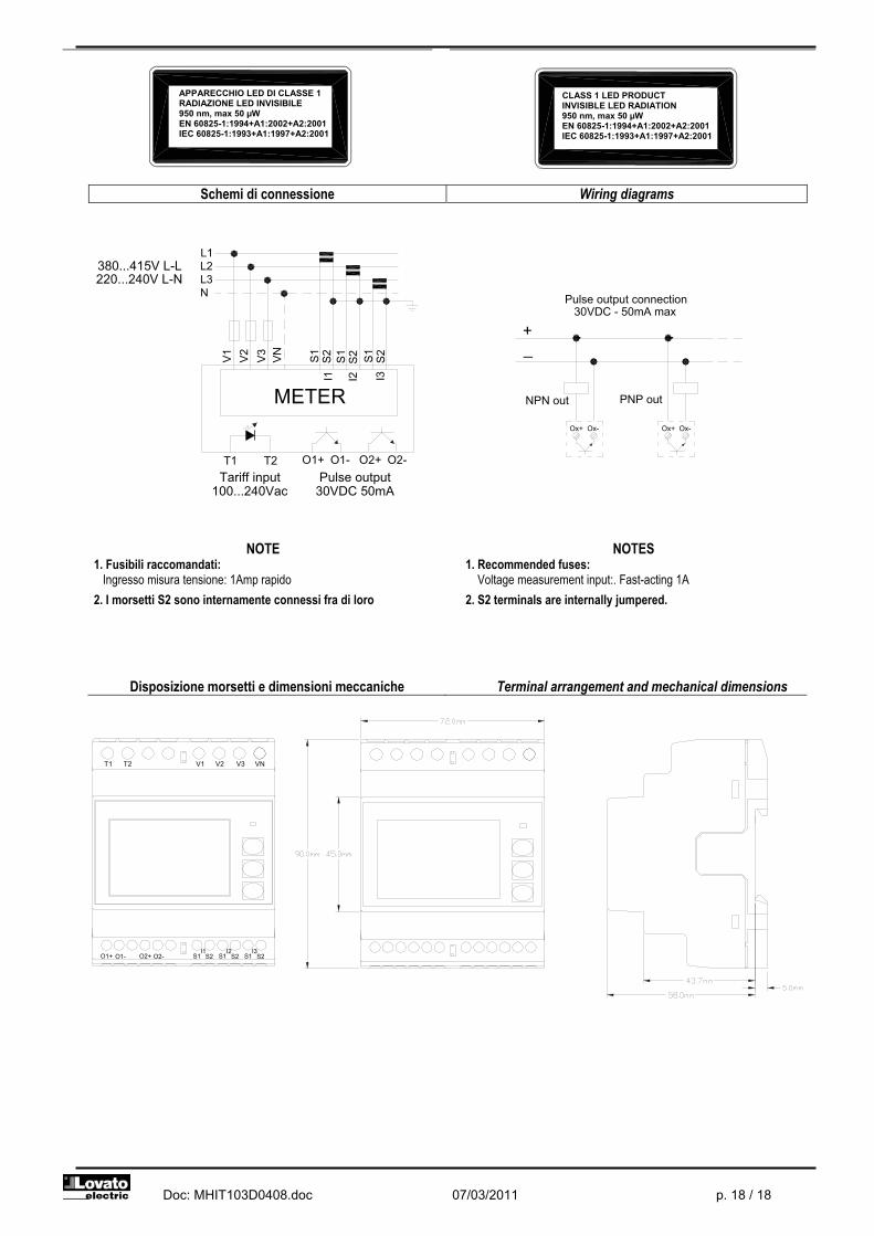
Doc: MHIT103D0408.doc 07/03/2011 p. 18 / 18
Schemi di connessione Wiring diagrams
NOTE 1. Fusibili raccomandati: Ingresso misura tensione: 1Amp rapido
2. I morsetti S2 sono internamente connessi fra di loro
NOTES 1. Recommended fuses: Voltage measurement input:. Fast-acting 1A
2. S2 terminals are internally jumpered.
Disposizione morsetti e dimensioni meccaniche Terminal arrangement and mechanical dimensions
APPARECCHIO LED DI CLASSE 1 RADIAZIONE LED INVISIBILE 950 nm, max 50 μW EN 60825-1:1994+A1:2002+A2:2001 IEC 60825-1:1993+A1:1997+A2:2001
CLASS 1 LED PRODUCT INVISIBLE LED RADIATION 950 nm, max 50 μW EN 60825-1:1994+A1:2002+A2:2001 IEC 60825-1:1993+A1:1997+A2:2001
S2O1-O1+ O2+ O2-I1
S1 S2S2S1I2
S1I3
T2T1 V1 VNV2 V3
220...240V L-N380...415V L-L
Tariff input Pulse output100...240Vac
METER
O1+T1 T2
N
V1
L2L3
L1V
3V
2
VN
I2I1 I3
O2+O1- O2-
S2
S1
S2S1
S2 S1
30VDC 50mA
PNP out
_
NPN out
Ox-Ox+
+
Ox+ Ox-
Pulse output connection30VDC - 50mA max