I - Libretto di istruzioni pag. 2-6 GB - Instructions ... I - Libretto di istruzioni pag. 2-6 GB -...
7
I - Libretto di istruzioni pag. 2-6 GB - Instructions Manual pages 7-11 F - Notice de montage pages 12-16 D - Betriebsanleitung Seite 17-21 COD.690L LETTORE DA INCASSO ITEM 690L CARD READER PARTIAL RECESS CODE 690L LECTEUR à ENCASTRER ARTIKEL 690L KARTENLESER UP-MONTAGE COD.694L TESSERA DI COMANDO ITEM 694L CONTROL CARD CODE 694L CARTE DE COMMANDE ARTIKEL 694L BEDIENUNGS-KARTE COD.695L PORTACHIAVI DI COMANDO ITEM 695L CONTROL KEYRING CODE 695L PORTE-CLEFS DE COMMANDE ARTIKEL 695L BEDIENUNGS-SCHLüSSELRING COD.697L SAPE BOX CON SOFTWARE DI GESTIONE SU PC ITEM 697L SAPE BOX AND MANAGEMENT SOFTWARE FOR PC CODE 697L SAPE BOX AVEC LOGICIREL DE GESTION SUR PC ARTIKEL 697L SAPE BOX UND MANAGEMENT- SOFTWARE FüR PC COD.691L LETTORE DA PARETE ITEM 691L CARD READER SURFACECODE CODE 691L LECTEUR EN SAILLIE ARTIKEL 691L KARTENLESER AP-MONTAGE COD.692L RICEVITORE ITEM 692L RECEIVER CODE 692L RéCEPTEUR ARTIKEL 692L EMPFäNGER COD.693L TESSERE DI INSTALLAZIONE ITEM 693L INSTALLATION CARDS CODE 693L CARTES D'INSTALLATION ARTIKEL 693L INSTALLATIONS-KARTEN led GREEN list 1 list 2 memory set led BLUE memory Sistema di apertura di prossimità Proximity card access control Système d'ouverture de proximité Proximity-Öffnungssystem
Transcript of I - Libretto di istruzioni pag. 2-6 GB - Instructions ... I - Libretto di istruzioni pag. 2-6 GB -...
I - Libretto di istruzioni pag. 2-6
GB - Instructions Manual pages 7-11
F - Notice de montage pages 12-16
D - Betriebsanleitung Seite 17-21
cod.690L LEttorE da incassoitEm 690L card rEadEr partiaL rEcEsscodE 690L LEctEur à EncastrErartikEL 690L kartEnLEsEr up-montagE
cod.694L tEssEra di comandoitEm 694L controL cardcodE 694L cartE dE commandEartikEL 694L BEdiEnungs-kartE
cod.695L portachiavi di comandoitEm 695L controL kEyringcodE 695L portE-cLEfs dE commandEartikEL 695L BEdiEnungs-schLüssELring
cod.697L sapE Box con softwarE di gEstionE su pcitEm 697L sapE Box and managEmEnt softwarE for pccodE 697L sapE Box avEc LogicirEL dE gEstion sur pcartikEL 697L sapE Box und managEmEnt- softwarE für pc
cod.691L LEttorE da parEtEitEm 691L card rEadEr surfacEcodE codE 691L LEctEur En saiLLiEartikEL 691L kartEnLEsEr ap-montagE
cod.692L ricEvitorEitEm 692L rEcEivEr codE 692L récEptEurartikEL 692L EmpfängEr
cod.693L tEssErE di instaLLazionEitEm 693L instaLLation cards codE 693L cartEs d'instaLLationartikEL 693L instaLLations-kartEn
Prit 19
Sech 15
pag.2
VERDEROSSABLU
12V
X
Y
Z
!
ledGREEN
list 1list 2
memoryset
ledBLUE
memory
Prit 19
Sech 15
pag.2
VERDEROSSABLU
12V
X
Y
Z
!
ledGREEN
list 1list 2
memoryset
ledBLUE
memory
Prit 19
Sech 15
pag.2
VERDEROSSABLU
12V
X
Y
Z
!
ledGREEN
list 1list 2
memoryset
ledBLUE
memory
Prit 19
Sech 15
pag.2
VERDEROSSABLU
12V
X
Y
Z
!
ledGREEN
list 1list 2
memoryset
ledBLUE
memory
Prit 19
Sech 15
pag.2
VERDEROSSABLU
12V
X
Y
Z
!
ledGREEN
list 1list 2
memoryset
ledBLUE
memory
Prit 19
Sech 15
pag.2
VERDEROSSABLU
12V
X
Y
Z
!
ledGREEN
list 1list 2
memoryset
ledBLUE
memory
Prit 19
Sech 15
pag.2
VERDEROSSABLU
12V
X
Y
Z
!
ledGREEN
list 1list 2
memoryset
ledBLUE
memory
Sistema di apertura di prossimitàProximity card access controlSystème d'ouverture de proximitéProximity-Öffnungssystem
page 7
gB SAPE 69
Prit 19
Sech 15
pag.2
VERDEROSSABLU
12V
X
Y
Z
!
ledGREEN
list 1list 2
memoryset
ledBLUE
memory
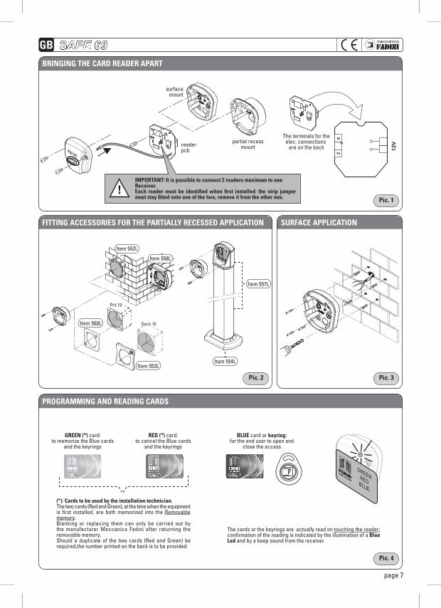
Bringing thE card rEadEr apart
surface mount
important: it is possible to connect 2 readers maximum to one receiver. Each reader must be identified when first installed: the strip jumper must stay fitted onto one of the two, remove it from the other one.
partial recessmount
The terminals for the elec. connections are on the back
pic. 1
pic. 3
pic. 4
pic. 2
Prit 19
Sech 15
pag.2
VERDEROSSABLU
12V
X
Y
Z
!
ledGREEN
list 1list 2
memoryset
ledBLUE
memory
Prit 19
Sech 15
pag.2
VERDEROSSABLU
12V
X
Y
Z
!
ledGREEN
list 1list 2
memoryset
ledBLUE
memory
Prit 19
Sech 15
pag.2
VERDEROSSABLU
12V
X
Y
Z
!
ledGREEN
list 1list 2
memoryset
ledBLUE
memory
fitting accEssoriEs for thE partiaLLy rEcEssEd appLication surfacE appLication
programming and rEading cards
Item 552L
Item 560L
Item 558L
Item 553LItem 554L
Item 557L
(*): cards to be used by the installation technician.The two cards (Red and Green), at the time when the equipment is first installed, are both memorized into the Removable memory. Blanking or replacing them can only be carried out by the manufacturer Meccanica Fadini after returning the removable memory. Should a duplicate of the two cards (Red and Green) be required,the number printed on the back is to be provided.
The cards or the keyrings are actually read on touching the reader; confirmation of the reading is indicated by the illumination of a Blue Led and by a beep sound from the receiver.
grEEn (*) card:to memorize the Blue cards
and the keyrings
rEd (*) card:to cancel the Blue cards
and the keyrings
BLuE card or keyring:for the end user to open and
close the access
readerpcb
GREENREDBLUE
gB
page 8
SAPE 69
X
Y
ZX
Y
Z
C NO YX Z
12V
ONOFF
2) 3) 4)
2) 3)
pag.3
!
1)
1
ON
2)
ON
2 3
ON
TUTTI I DIP IN OFF3)
1
OFF
3
OFF
2
OFF
30 sec
pag.4
!
1)
1
ON ON
2oppure ....
1)
1
ON ON
2oppure
4)
....
oppure
4)
!
!
12
3
+ +
3 47
VERDE
ROSSA
BLU VERDE
BLU ROSSA
ROSSA
!
oppure
1ONOFF
12
3
12V
12V
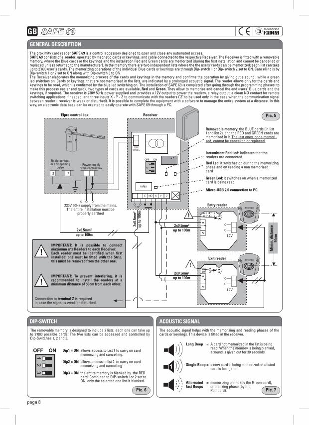
The proximity card reader sapE 69 is a control accessory designed to open and close any automated access. sapE 69 consists of a reader, operated by magnetic cards or keyrings, and cable connected to the respective receiver. The Receiver is fitted with a removable memory, where the Blue cards or the keyrings and the installation Red and Green cards are memorized (during the first installation and cannot be cancelled or replaced unless returned to the manufacturer). In the memory there are two independent lists where the the users'cards can be memorized; each list can take up to 2'000 user's cards. The memorizing operations of the individual Blue cards or keyrings are through Dip-swtch 1 or Dip-switch 2 set to ON. Cancelling is by Dip-switch 1 or 2 set to ON along with Dip-switch 3 to ON.The Receiver elaborates the memorizing process of the cards and keyrings in the memory and confirms the operation by giving out a sound , while a green led switches on. Cards or keyrings, that are not memorized in the lists, are indicated by a prolonged acoustic signal. The reader allows only for the cards and keyrings to be read, which is confirmed by the blue led switching on. The installation of SAPE 69 is completed after going through the programming phases: to make this process easier and quick, two types of cards are available, red and green. They allow to memorize and cancel the end users' Blue cards and the keyrings, if required. The receiver is 230V 50Hz power supplied and provides a 12V output to power the readers, a relay output, a clean NO contact for remote switching applications if needed, and three inputs X - Y - Z to communicate with the readers ("Z" to be used only in the case when the communication signal between reader - receiver is weak or disturbed). It is possible to complete the equipment with a software to manage the entire system at a distance. In this way, an electronic data base can be created to easily operate with SAPE 69 through a PC.
pic. 7
pic. 5
pic. 6
gEnEraL dEscription
dip-switch acoustic signaL
Elpro control box
Exit reader
Entry reader
receiver
Radio contact or any opening
pulsePower supply
from control box
230V 50Hz supply from the mains.The entire installation must be
properly earthed
2x0.5mm²up to 100m
2x0.5mm²up to 100m
2x0.5mm²up to 100m
2x0.
5mm
²up
to 1
00m
min
im. d
ista
nce
50cm
removable memory: the BLUE cards (in list 1and list 2), and the RED and GREEN cards are memorized in it. The last ones, once memori-zed, cannot be cancelled or replaced.
intermittent red Led: indicates that the readers are connected.
red Led: it switches on during the memorizing phase and on reading a non memorizedcard
green Led: it switches on when a memorized card is being read.
micro-usB 2.0 connection to pc.
230V50/60Hz
relay
important: it is possible to connect maximum n°2 readers to each receiver. Each reader must be identified when first installed: one must be fitted with the strip, this must be removed from the other one.
important: to prevent interfering, it is recommended to install the readers at a minimum distance of 50cm from each other.
Connection to terminal z is requiredin case the signal is weak or disturbed.
X
Y
ZX
Y
Z
C NO YX Z
12V
ONOFF
2) 3) 4)
2) 3)
pag.3
!
1)
1
ON
2)
ON
2 3
ON
TUTTI I DIP IN OFF3)
1
OFF
3
OFF
2
OFF
30 sec
pag.4
!
1)
1
ON ON
2oppure ....
1)
1
ON ON
2oppure
4)
....
oppure
4)
!
!
12
3
+ +
3 47
VERDE
ROSSA
BLU VERDE
BLU ROSSA
ROSSA
!
oppure
1ONOFF
12
3
12V
12V
X
Y
ZX
Y
Z
C NO YX Z
12V
ONOFF
2) 3) 4)
2) 3)
pag.3
!
1)
1
ON
2)
ON
2 3
ON
TUTTI I DIP IN OFF3)
1
OFF
3
OFF
2
OFF
30 sec
pag.4
!
1)
1
ON ON
2oppure ....
1)
1
ON ON
2oppure
4)
....
oppure
4)
!
!
12
3
+ +
3 47
VERDE
ROSSA
BLU VERDE
BLU ROSSA
ROSSA
!
oppure
1ONOFF
12
3
12V
12V
The removable memory is designed to include 2 lists, each one can take up to 2'000 possible cards. The two lists can be accessed and controlled by Dip-Switches 1, 2 and 3.
The acoustic signal helps with the memorizing and reading phases of the cards or keyrings. This device is fitted in the receiver.
dip1 = on allows access to List 1 to carry on card memorizing and cancelling.
dip2 = on allows access to list 2 to carry on card memorizing and cancelling
dip3 = on the entire memory is blanked by the RED card. Combined to DIP-switch 1or 2 set to ON, only the selected one list is blanked.
Long Beep = A card not memorized in the list is being read. when the memory is being blanked, a sound is given out for 30 seconds.
single Beep = a new card is being memorized or a listed card is being read.
alternated = memorizing phase (by the Green card),fast Beeps or blanking phase (by the Red card).
page 9
gB SAPE 69
X
Y
ZX
Y
Z
C NO YX Z
12V
ONOFF
2) 3) 4)
2) 3)
pag.3
!
1)
1
ON
2)
ON
2 3
ON
TUTTI I DIP IN OFF3)
1
OFF
3
OFF
2
OFF
30 sec
pag.4
!
1)
1
ON ON
2oppure ....
1)
1
ON ON
2oppure
4)
....
oppure
4)
!
!
12
3
+ +
3 47
VERDE
ROSSA
BLU VERDE
BLU ROSSA
ROSSA
!
oppure
1ONOFF
12
3
12V
12V
X
Y
ZX
Y
Z
C NO YX Z
12V
ONOFF
2) 3) 4)
2) 3)
pag.3
!
1)
1
ON
2)
ON
2 3
ON
TUTTI I DIP IN OFF3)
1
OFF
3
OFF
2
OFF
30 sec
pag.4
!
1)
1
ON ON
2oppure ....
1)
1
ON ON
2oppure
4)
....
oppure
4)
!
!
12
3
+ +
3 47
VERDE
ROSSA
BLU VERDE
BLU ROSSA
ROSSA
!
oppure
1ONOFF
12
3
12V
12V
X
Y
ZX
Y
Z
C NO YX Z
12V
ONOFF
2) 3) 4)
2) 3)
pag.3
!
1)
1
ON
2)
ON
2 3
ON
TUTTI I DIP IN OFF3)
1
OFF
3
OFF
2
OFF
30 sec
pag.4
!
1)
1
ON ON
2oppure ....
1)
1
ON ON
2oppure
4)
....
oppure
4)
!
!
12
3
+ +
3 47
VERDE
ROSSA
BLU VERDE
BLU ROSSA
ROSSA
!
oppure
1ONOFF
12
3
12V
12V
X
Y
ZX
Y
Z
C NO YX Z
12V
ONOFF
2) 3) 4)
2) 3)
pag.3
!
1)
1
ON
2)
ON
2 3
ON
TUTTI I DIP IN OFF3)
1
OFF
3
OFF
2
OFF
30 sec
pag.4
!
1)
1
ON ON
2oppure ....
1)
1
ON ON
2oppure
4)
....
oppure
4)
!
!
12
3
+ +
3 47
VERDE
ROSSA
BLU VERDE
BLU ROSSA
ROSSA
!
oppure
1ONOFF
12
3
12V
12V
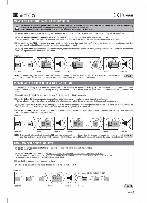
important: when the equipment is first installed, and the green card is read and therefore memorized into the system, the red card is automatically memorized, too. Both cannot be cancelled or replaced, only the manufacturer can do this.in this way the installation is uniquely controlled by the possessor of the green and red cards.
mEmorizing thE BLuE cards or thE kEyrings
individuaL BLuE cards or kEyrings cancELLing
totaL rEmovaL of List 1 or List 2
1) Set to on either dip-sw. 1 or dip-sw. 2 (only one of the two): Dip-sw. 1 to access list 1 (faster in reading than list 2), and Dip-sw. 2 to access list 2
2) Bring the grEEn card to touch one reader (in case of two readers. this operation can be carried on only with one of them). The red led in the receiver starts flashing and a fast, alternate acoustic signal can be heard, indicating that the memorizing process is on.
3) Bring, one by one, the BLuE cards or the keyrings to touch the reader to have them memorized (the Blue led on the Reader switches on whenever a card or a keyring is read; wait until it is off again before doing the same with other units).
4) Bring again the grEEn card to touch the reader once card/keyring memorizing is over. Should new cards/keyrings be required to be entered, wait 3 seconds and bring again the Green card to touch the reader.
Should any card or keyring be lost, removal from the system can be done only through the software by a PC ( it is understood that the names of the users/customers must be available in that they were previously memorized in the list), as an alternative the entire list is to be cancelled and the cards memorized again.
1) Set to on either dip 1 or dip 2 (only one of the two): Dip 1 to access list 1, Dip 2 to access list 2.
2) Bring the rEd card to touch one reader (in case of two readers, this operation can be carried on only with one of them). The red led in the receiver starts flashing and a fast, alternate acoustic signal can be heard, indicating that the cancelling process is on.
3) Bring, one by one, the BLuE cards or the keyrings to touch the reader to cancell them from the pre-selected list (the Blue led on the Reader switches on whenever a card or a keyring is read; wait until it is off again before doing the same with other units).
4) Bring again the rEd card to touch the reader once card/keyring cancelling is over. Should new cards/keyrings be required to be cancelled, wait 3 seconds and bring again the Red card to touch the reader.
1) Set to on the dip corresponding to the list required to be removed: Dip 1 for list1, and Dip 2 for list 2. Set to on even dip 3.
2) Bring the rEd card to touch one reader (in case of 2 readers, this operation can be carried on only with one of them). The red led in the receiver goes on and a sound can be heard for 30 seconds. During this time the entire selected list is deleted. But the two installer's cards, RED and GREEN, are not disabled.
3) Once the 30 seconds are over, the memory is blanked.
4) On the red led going off and the sound stopping, set all of the dip-switches to OFF.
notE: Once memorizing is completed, unless the GREEN card is brought to touch the reader in 1 minute's time, the procedure is closed, but the cards/keyrings are retained in the memory. If the RED card is used by mistake, the procedure is interrupted.
notE: Once cancelling is completed, unless the RED card touches the reader in 1 minute's time, the procedure is closed, anyway the previously cancelled cards/keyrings are no longer in the memory. If the GREEN card is brought to touch the reader by mistake, the procedure is interrupted.
diagram
diagram
diagram
receiver
receiver
receiver
reader
reader
reader
receiver
receiver
receiver
receiver
receiver
reader
reader
receiver
reader
reader
pic. 8
pic. 9
pic. 10
Green
reD
Green
reD
BLUe
BLUe
or
or
or or
ALL OF THE DIP-SWITCHES TO OFF
reD
gB
page 10
softwarE sapE 69 for pc managEmEnt
pic. 11
pic. 12
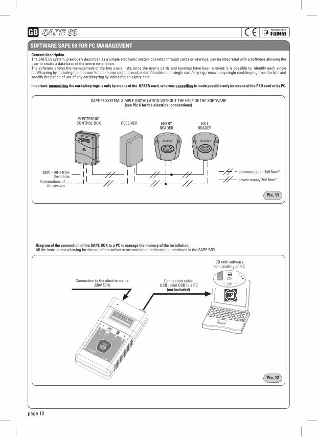
general descriptionThe SAPE 69 system, previously described as a simple electronic system operated through cards or keyrings, can be integrated with a software allowing the user to create a data base of the entire installation. The software allows the management of the two users' lists, once the user's cards and keyrings have been entered: it is possible to identify each single card/keyring by including the end user's data (name and address), enable/disable each single card/keyring, remove any single card/keyring from the lists and specify the period of use of any card/keyring by indicating an expiry date.
important: memorizing the cards/keyrings is only by means of the grEEn card, whereas cancelling is made possible only by means of the rEd card or by pc.
SAPE 69 SYSTEM: SIMPLE INSTALLATION wITHOUT THE HELP OF THE SOFTwARE(see pic.6 for the electrical connections)
ELECTRONICCONTROL BOX RECEIVER ENTRY
READEREXIT
READER
pag.5 pag.6
2525
50
Ø56
3670 mm
72
8757
127
ledGREEN
list 1list 2
memoryset
ledBLUE
memory
230V - 50Hz from the mains
communication 2x0.5mm²
power supply 2x0.5mm²Connections of the system
pag.5 pag.6
2525
50
Ø56
3670 mm
72
8757
127
ledGREEN
list 1list 2
memoryset
ledBLUE
memory
Connection to the electric mains 230V 50Hz
diagram of the connection of the sapE Box to a pc to manage the memory of the installation.All the instructions allowing for the use of the software are contained in the manual enclosed in the SAPE BOX.
Connection cable USB - mini USB to a PC
(not included)
CD with software for installing on PC
SAPE 69
gB
page 11
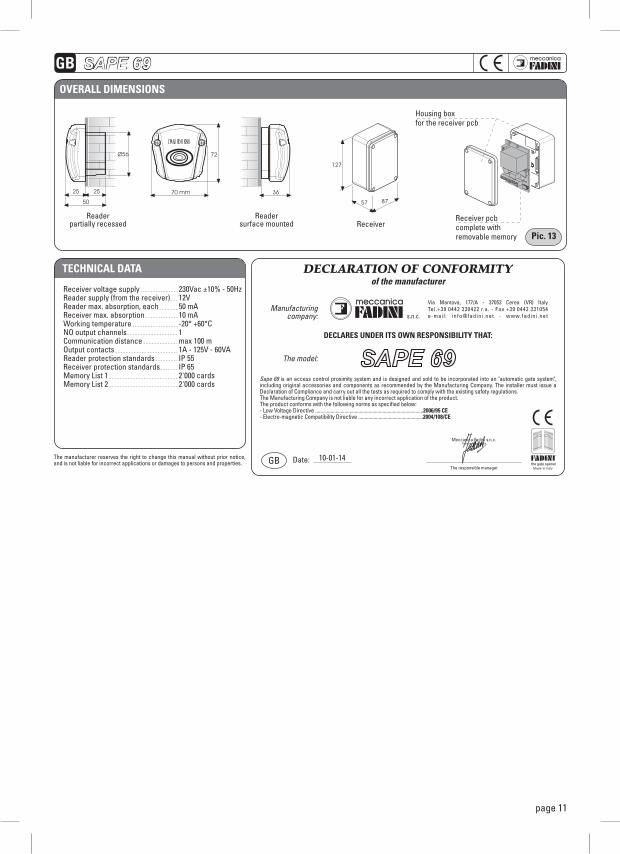
tEchnicaL data
Receiver voltage supplyReader supply (from the receiver)Reader max. absorption, eachReceiver max. absorptionworking temperatureNO output channelsCommunication distanceOutput contactsReader protection standardsReceiver protection standardsMemory List 1 Memory List 2
230Vac ±10% - 50Hz12V50 mA10 mA-20° +60°C1max 100 m1A - 125V - 60VAIP 55IP 65 2'000 cards2'000 cards
DECLARATION OF CONFORMITYof the manufacturer
s.n.c.
Via Mantova, 177/A - 37053 Cerea (VR) ItalyTel.+39 0442 330422 r.a. - Fax +39 0442 331054e-mai l : in fo@fadin i .net - www.fadin i .net
Manufacturing company:
DECLARES UNDER ITS OWN RESPONSIBILITY THAT:
The model:
Sape 69 is an access control proximity system and is designed and sold to be incorporated into an "automatic gate system", including original accessories and components as recommended by the Manufacturing Company. The installer must issue a Declaration of Compliance and carry out all the tests as required to comply with the existing safety regulations.The Manufacturing Company is not liable for any incorrect application of the product.The product conforms with the following norms as specified below:- Low Voltage Directive .....................................................................................2006/95 CE- Electro-magnetic Compatibility Directive ...................................................2004/108/CE
The responsible manager
Meccanica Fadini s.n.c.Direttore Responsabile
GB Date: 10-01-14the gate opener
The manufacturer reserves the right to change this manual without prior notice, and is not liable for incorrect applications or damages to persons and properties.
pag.5 pag.6
2525
50
Ø56
3670 mm
72
8757
127
ledGREEN
list 1list 2
memoryset
ledBLUE
memory
ovEraLL dimEnsions
Housing boxfor the receiver pcb
Receiver pcbcomplete withremovable memory
Readerpartially recessed
Readersurface mounted Receiver
pic. 13
SAPE 69
La Ditta costruttrice si riserva di apportare modifiche al presente libretto senza preavviso, inoltre non si assume nessuna responsabilità per eventuali errori o danni a cose e persone.
The manufacturing firm reserves the right to modify this manual without notice; in addition it assumes no responsibility for possible errors or damages to properties or persons.
Le fabricant se réserve le droit de modifier ce manuel d’instructions sans préavis et décline toute responsabilité en cas d’erreurs et/ou dommages matériels ou personnels.
Der Hersteller behält sich vor, etwaige Änderungen an diesem Handbuch ohne Vorankündigung vorzunehmen und übernimmt für etwaige Fehler bzw. Sach- und Personenschäden keinerlei Haftung.
Via Mantova, 177/A - 37053 Cerea (VR) Italy - Tel. +39 0442 330422 - Fax +39 0442 331054e-mail: [email protected] - www.fadini.net
Timbro dell’InstallatoreInstaller’s StampCachet de l’installateurStempel des Installateurs
06-2
014


![Sezione 9 gb - Moto-Abruzzo · 2019. 9. 22. · ETV mille Rally SUMMARY 9.1. ... [1000 km (625 miles)] Every 7500 km (4687 miles) or 12 months Every 15000 km ... (as per the instructions](https://static.fdocumenti.com/doc/165x107/60cfab357d413727970f4204/sezione-9-gb-moto-abruzzo-2019-9-22-etv-mille-rally-summary-91-1000.jpg)