HT - danasac.ie · elevate pressioni di esercizio e lunga durata. Heavy duty, roller type stator...
19
MOTORI ORBITALI HYDRAULIC MOTOR SERIES HT G/1 COD. 06-0112-A19
Transcript of HT - danasac.ie · elevate pressioni di esercizio e lunga durata. Heavy duty, roller type stator...
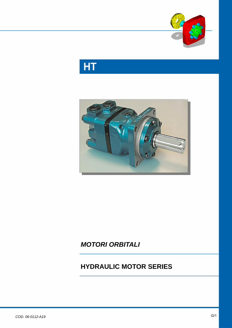
MOTORI ORBITALI
HYDRAULIC MOTOR SERIES
HT
G/1 COD. 06-0112-A19
G/2 orbital
R
orbitalorbital
R
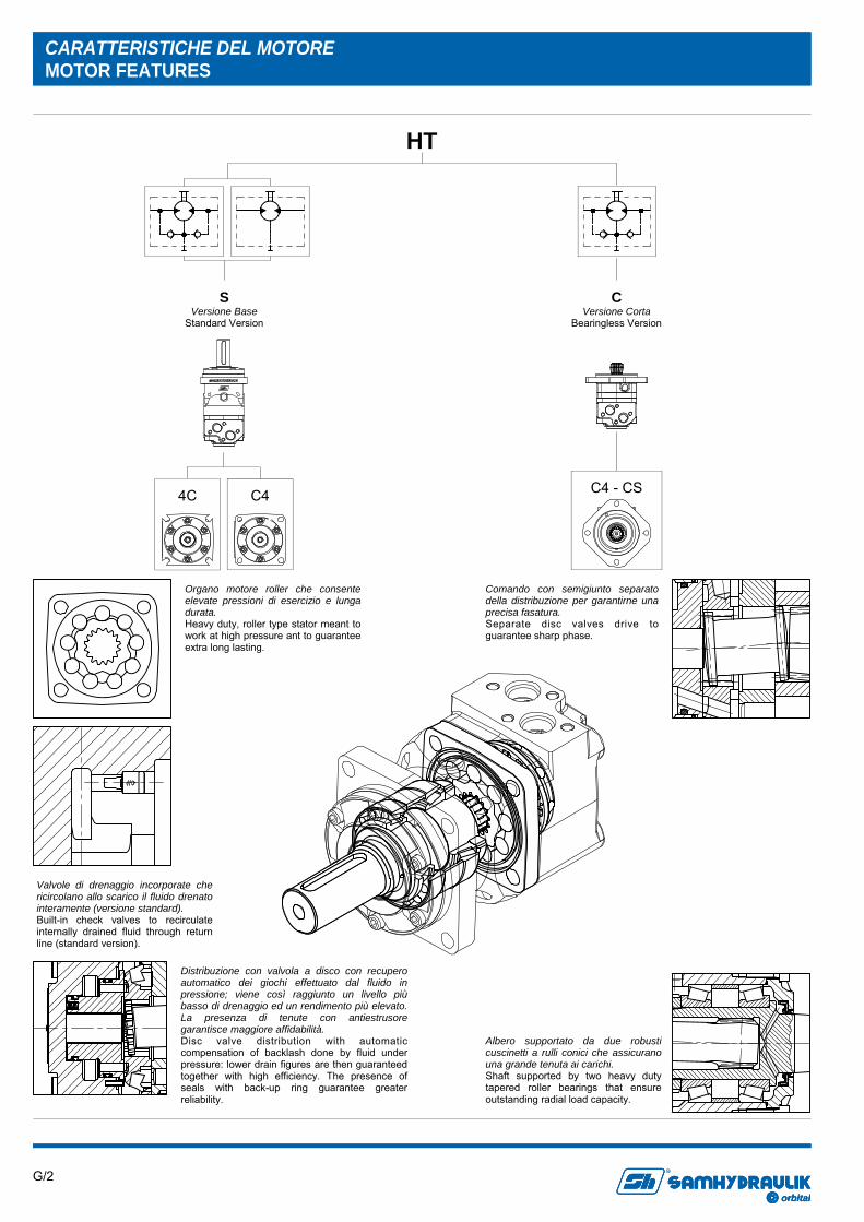
Organo motore roller che consente elevate pressioni di esercizio e lunga durata. Heavy duty, roller type stator meant to work at high pressure ant to guarantee extra long lasting.
Comando con semigiunto separato della distribuzione per garantirne una precisa fasatura. Separate disc valves drive to guarantee sharp phase.
Valvole di drenaggio incorporate che ricircolano allo scarico il fluido drenato interamente (versione standard). Built-in check valves to recirculate internally drained fluid through return line (standard version).
Albero supportato da due robusti cuscinetti a rulli conici che assicurano una grande tenuta ai carichi. Shaft supported by two heavy duty tapered roller bearings that ensure outstanding radial load capacity.
CARATTERISTICHE DEL MOTORE MOTOR FEATURES
Distribuzione con valvola a disco con recupero automatico dei giochi effettuato dal fluido in pressione; viene così raggiunto un livello più basso di drenaggio ed un rendimento più elevato. La presenza di tenute con antiestrusore garantisce maggiore affidabilità. Disc valve distribution with automatic compensation of backlash done by fluid under pressure: lower drain figures are then guaranteed together with high efficiency. The presence of seals with back-up ring guarantee greater reliability.
C Versione Corta
Bearingless Version
HT
C4 - CS
S Versione Base
Standard Version
4C C4
G/3 orbital
R
orbitalorbital
R
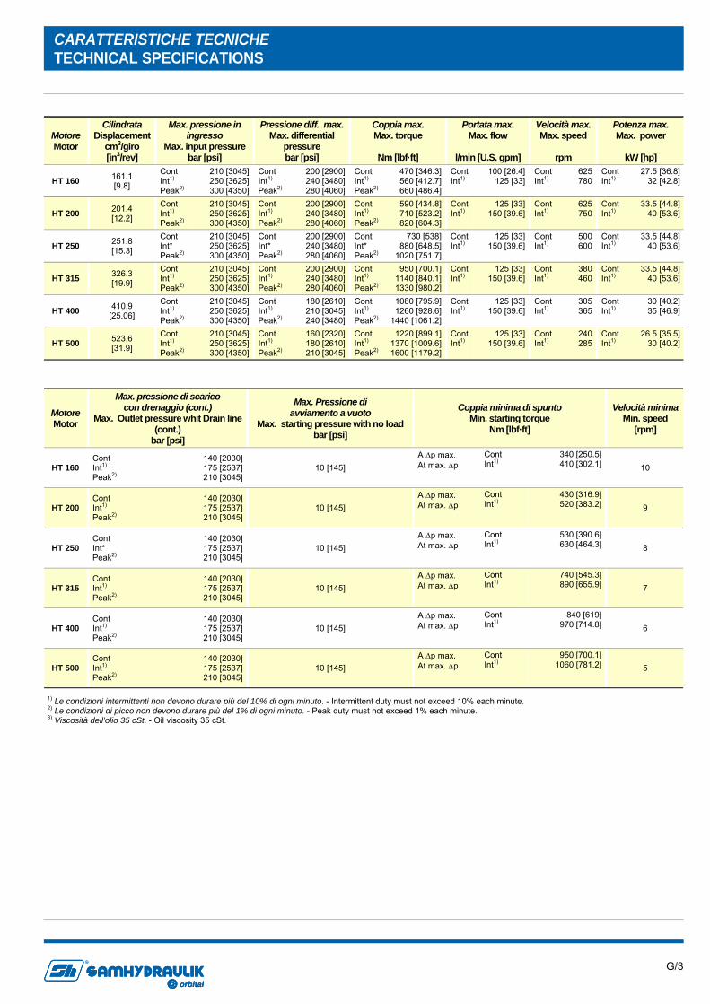
1) Le condizioni intermittenti non devono durare più del 10% di ogni minuto. - Intermittent duty must not exceed 10% each minute. 2) Le condizioni di picco non devono durare più del 1% di ogni minuto. - Peak duty must not exceed 1% each minute. 3) Viscosità dell’olio 35 cSt. - Oil viscosity 35 cSt.
Motore Motor
Cilindrata Displacement
cm3/giro [in3/rev]
Max. pressione in ingresso
Max. input pressure bar [psi]
Pressione diff. max. Max. differential
pressure bar [psi]
Coppia max. Max. torque
Nm [lbf·ft]
Portata max. Max. flow
l/min [U.S. gpm]
Velocità max. Max. speed
rpm
Potenza max. Max. power
kW [hp]
HT 160 161.1 [9.8]
Cont Int1) Peak2)
210 [3045] 250 [3625] 300 [4350]
Cont Int1) Peak2)
200 [2900] 240 [3480] 280 [4060]
Cont Int1) Peak2)
470 [346.3] 560 [412.7] 660 [486.4]
Cont Int1)
100 [26.4] 125 [33]
Cont Int1)
625 780
Cont Int1)
27.5 [36.8] 32 [42.8]
HT 200 201.4 [12.2]
Cont Int1) Peak2)
210 [3045] 250 [3625] 300 [4350]
Cont Int1) Peak2)
200 [2900] 240 [3480] 280 [4060]
Cont Int1) Peak2)
590 [434.8] 710 [523.2] 820 [604.3]
Cont Int1)
125 [33] 150 [39.6]
Cont Int1)
625 750
Cont Int1)
33.5 [44.8] 40 [53.6]
HT 250 251.8 [15.3]
Cont Int* Peak2)
210 [3045] 250 [3625] 300 [4350]
Cont Int* Peak2)
200 [2900] 240 [3480] 280 [4060]
Cont Int* Peak2)
730 [538] 880 [648.5]
1020 [751.7]
Cont Int1)
125 [33] 150 [39.6]
Cont Int1)
500 600
Cont Int1)
33.5 [44.8] 40 [53.6]
HT 315 326.3 [19.9]
Cont Int1) Peak2)
210 [3045] 250 [3625] 300 [4350]
Cont Int1) Peak2)
200 [2900] 240 [3480] 280 [4060]
Cont Int1) Peak2)
950 [700.1] 1140 [840.1] 1330 [980.2]
Cont Int1)
125 [33] 150 [39.6]
Cont Int1)
380 460
Cont Int1)
33.5 [44.8] 40 [53.6]
HT 400 410.9 [25.06]
Cont Int1) Peak2)
210 [3045] 250 [3625] 300 [4350]
Cont Int1) Peak2)
180 [2610] 210 [3045] 240 [3480]
Cont Int1) Peak2)
1080 [795.9] 1260 [928.6]
1440 [1061.2]
Cont Int1)
125 [33] 150 [39.6]
Cont Int1)
305 365
Cont Int1)
30 [40.2] 35 [46.9]
HT 500 523.6 [31.9]
Cont Int1) Peak2)
210 [3045] 250 [3625] 300 [4350]
Cont Int1) Peak2)
160 [2320] 180 [2610] 210 [3045]
Cont Int1) Peak2)
1220 [899.1] 1370 [1009.6] 1600 [1179.2]
Cont Int1)
125 [33] 150 [39.6]
Cont Int1)
240 285
Cont Int1)
26.5 [35.5] 30 [40.2]
Motore Motor
Max. pressione di scarico con drenaggio (cont.)
Max. Outlet pressure whit Drain line (cont.)
bar [psi]
Max. Pressione di avviamento a vuoto
Max. starting pressure with no load bar [psi]
Coppia minima di spunto Min. starting torque
Nm [lbf·ft]
Velocità minima Min. speed
[rpm]
HT 160 Cont Int1) Peak2)
140 [2030] 175 [2537] 210 [3045]
10 [145] A Δp max. At max. Δp
Cont Int1)
340 [250.5] 410 [302.1] 10
HT 200 Cont Int1) Peak2)
140 [2030] 175 [2537] 210 [3045]
10 [145] A Δp max. At max. Δp
Cont Int1)
430 [316.9] 520 [383.2] 9
HT 250 Cont Int* Peak2)
140 [2030] 175 [2537] 210 [3045]
10 [145] A Δp max. At max. Δp
Cont Int1)
530 [390.6] 630 [464.3] 8
HT 315 Cont Int1) Peak2)
140 [2030] 175 [2537] 210 [3045]
10 [145] A Δp max. At max. Δp
Cont Int1)
740 [545.3] 890 [655.9] 7
HT 400 Cont Int1) Peak2)
140 [2030] 175 [2537] 210 [3045]
10 [145] A Δp max. At max. Δp
Cont Int1)
840 [619] 970 [714.8] 6
HT 500 Cont Int1) Peak2)
140 [2030] 175 [2537] 210 [3045]
10 [145] A Δp max. At max. Δp
Cont Int1)
950 [700.1] 1060 [781.2] 5
CARATTERISTICHE TECNICHE TECHNICAL SPECIFICATIONS

G/4 orbital
R
orbitalorbital
R
MASSIMA PRESSIONE AMMESSA SULLA GUARNIZIONE ALBERO MAX PERMISSIBLE SHAFT SEAL PRESSURE
Pressione massima di scarico senza drenaggio o massima pressione nella linea di drenaggio. I motori sono forniti nella versione con guarnizioni standard (diagramma Standard) o nella versione con guarnizioni ad alta pressione (diagramma HPS). Per condizioni di pressione e velocità non contemplate dal presente grafico si consiglia di contattare la S.A.M. Hydraulik.
Max. return pressure without drain line or max. pressure in the drain line. Motor are supplied in standard seal version (Standard chart) or in HPS seal version (HPS chart). For pressure and speeds not showed in the curve below, please contact S.A.M. Hydraulik.
PERDITE DI CARICO PER ATTRAVERSAMENTO PRESSURE LOSS
Il diagramma è stato ottenuto con prove eseguite su un numero significativo di motori, utilizzando un olio avente una viscosità cinematica di 37 cSt alla temperatura di 45 C°. Diagram according to tests done with a relevant number of motors and using hydraulic oil with kinematic viscosity of 37 cSt at 45 C° temperature.
HPS STANDARD
G/5 orbital
R
orbitalorbital
R
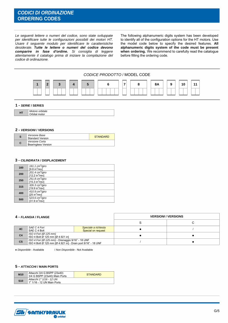
CODICE PRODOTTO / MODEL CODE
HT Motore orbitale Orbital motor
1 - SERIE / SERIES
160 161.1 cm3/giro [9.8 in3/rev]
200 201.4 cm3/giro [12.2 in3/rev]
250 251.8 cm3/giro [15.3 in3/rev]
315 326.3 cm3/giro [19.9 in3/rev]
400 410.9 cm3/giro [25 in3/rev]
500 523.6 cm3/giro [31.9 in3/rev]
3 - CILINDRATA / DISPLACEMENT
S Versione Base Standard Version STANDARD
C Versione Corta Bearingless Version
2 - VERSIONI / VERSIONS
VERSIONI / VERSIONS S C
4C SAE C 4 Fori SAE C 4 Bolt
Speciale a richiesta Special on request ● /
C4 ISO 4 Fori (Ø 125 mm) ISO 4 Bolt Ø 125 mm [Ø 4.921 in] ● ●
CS ISO 4 Fori (Ø 125 mm) - Drenaggio 9/16” - 18 UNF ISO 4 Bolt Ø 125 mm [Ø 4.921 in] - Drain port 9/16” - 18 UNF / ●
4 - FLANGIA / FLANGE
● Disponibile - Available / Non Disponibile - Not Available
2
3
7
6
8
8A
11
9
1
4
5 10
Le seguenti lettere o numeri del codice, sono state sviluppate per identificare tutte le configurazioni possibili dei motori HT. Usare il seguente modulo per identificare le caratteristiche desiderate. Tutte le lettere o numeri del codice devono comparire in fase d’ordine. Si consiglia di leggere attentamente il catalogo prima di iniziare la compilazione del codice di ordinazione.
The following alphanumeric digits system has been developed to identify all of the configuration options for the HT motors. Use the model code below to specify the desired features. All alphanumeric digits system of the code must be present when ordering. We recommend to carefully read the catalogue before filling the ordering code.
CODICI DI ORDINAZIONE ORDERING CODES
M10 Attacchi 3/4 G BSPP (23x40) 3/4 G BSPP (23x40) Main Ports STANDARD
S10 Attacchi 1" 1/16 - 12 UN 1" 1/16 - 12 UN Main Ports
5 - ATTACCHI / MAIN PORTS
G/6 orbital
R
orbitalorbital
R
N NBR STANDARD V FKM
7 - TENUTE / SEALS
S C
DB002 Semigiunto Z=16 12/24 DP Dog Bone T=16 12/24 DP / ●
CL400 Albero Cilindrico Ø40 mm Ø40 mm [1.56 in] Parallel keyed ● /
C3800 Albero Cilindrico Ø38 mm Ø38 mm [1.48 in] Parallel keyed ● /
CN400 Albero Conico (Disponibile solo con flangia C4 e attacchi M10) Tapered Shaft (Available only with mount flange C4 and M10 Main Ports) ● /
SC380 Albero Scanalato (profilo ANS B 92.1 / 1970 12/24 DP Z=17) Splined Shaft (ANS B 92.1 / 1970 12/24 DP Z=17 spline) ● /
VERSIONI / VERSIONS 6 - ESTREMITÀ ALBERO / SHAFT END
● Disponibile - Available / Non Disponibile - Not Available
ATTACCHI / MAIN PORTS
M10 S10
XXXX Non Richieste Not Required ● ●
M101 Valvola di massima pressione VAF 10 - D Pressure relief valve VAF 10 - D ● /
M102 Valvola di controllo bilanciata a doppio effetto VCR1 10 - D/AF Double-acting overcentre valve with shuttle valve VCR1 10 - D/AF ● /
M103 Valvola bilanciata di blocco e controllo discesa VCD2 10 - S/AF Overcentre Valve with VCD2 10 - S/AF ● /
Per le caratteristiche vedere il catalogo valvole For the feature see catalogue valves
● Disponibile - Available / Non Disponibile - Not Available
8 - VALVOLE / VALVES
VALVOLE / VALVES
XXXX M101 M102 M103
000 Caratteristica non necessaria Feature not necessary ● / / /
001 Non Tarata (Campo Taratura 100÷350 bar) - Senso di rotazione DX Not Set 100÷350 bar [1450 to 5075 psi] - Direction of rotation CW / / / ●
004 Non Tarata (Campo Taratura 30÷210 bar) - Senso di rotazione SX Not Set 30÷210 bar [435 to 3045 psi] - Direction of rotation CCW / / / ●
005 Non Tarata (Campo Taratura 100÷200 bar) Not Set 100÷200 bar [1450 to 2900 psi] / ● / /
006 Non Tarata (Campo Taratura 210÷300 bar) Not Set 210÷300 bar [3045 to 4350 psi] / ● / /
700 Rapporto di Pilotaggio 7:1 Pilot Ratio 7:1 / / ● /
100 Rapporto di Pilotaggio 10:1 Pilot Ratio 10:1 / / ● /
002 Non Tarata (Campo Taratura 100÷350 bar) - Senso di rotazione SX Not Set 100÷350 bar [1450 to 5075 psi] - Direction of rotation CCW / / / ●
003 Non Tarata (Campo Taratura 30÷210 bar) - Senso di rotazione DX Not Set 30÷210 bar [435 to 3045 psi] - Direction of rotation CW / / / ●
● Disponibile - Available / Non Disponibile - Not Available
8A - CARATTERISTICA VALVOLA / VALVES FEATURE
Per la fornitura di valvole tarate contattare Uff.Tecnico. Please contact Technical department for valve which requie specific setting
2
3
7
6
8
8A
11
9
1
4
5 10

G/7 orbital
R
orbitalorbital
R
XX Non Richieste Not Required
01 Verniciato Nero RAL 9005 Black Painted RAL 9005
11 - OPZIONI / OPTIONS
2
3
7
6
8
8A
11
9
1
4
5 10
XX Non Richieste Not Required
06 Valvola di lavaggio VSC/F - 6 l/min VSC/F Flushing valve - 6 l/min [1.58 U.S. gpm]
09 Valvola di lavaggio VSC/F - 10.5 l/min VSC/F Flushing valve - 10.5 l/min [2.77 U.S. gpm]
15 Valvola di lavaggio VSC/F - 15 l/min VSC/F Flushing valve - 15 l/min [3.96 U.S. gpm]
21 Valvola di lavaggio VSC/F - 20 l/min VSC/F Flushing valve - 20 l/min [5.28 U.S. gpm]
Per le caratteristiche vedere il catalogo valvole For the feature see catalogue valves
9 - VALVOLE DI LAVAGGIO / FLUSHING VALVES
E’ possibile combinare le valvole di lavaggio solo con la valvola VAF 10 - D It is possible to combine the flushing valves only with VAF 10 - D valve.
S C
XX Non Richiesta Not Required STANDARD ● ●
HP Guarnizione alta pressione High Pressure Seal ● /
HD Heavy duty (disponibile solo con attacchi M10, alberi CL400-CN400-SC380 e senza valvole interne di drenaggio)
Heavy duty (available only with M10 Main ports, CL400-CN400-SC380 shats and without internal check valves) ● /
DH Heavy duty (disponibile solo con attacchi M10, alberi CL400-CN400-SC380 e senza valvole interne di drenaggio) + Guarnizione alta pressione
Heavy duty (available only with M10 Main ports, CL400-CN400-SC380 shats and without internal check valves) + High Pressure Seal ● /
VERSIONI / VERSIONS
TS Tachimetro con predisposizione per sensore (disponibile solo con flangia C4) Tachometer with sensor arrangement (available only with C4 flange) ● /
TC Tachimetro con sensore con cavo lunghezza 2 metri (disponibile solo con flangia C4) Tachometer with sensor with 2 metres cable (available only with C4 flange) ● /
10 - CARATTERISTICA VERSIONE / VERSION FEATURE
● Disponibile - Available / Non Disponibile - Not Available
G/8 orbital
R
orbitalorbital
R
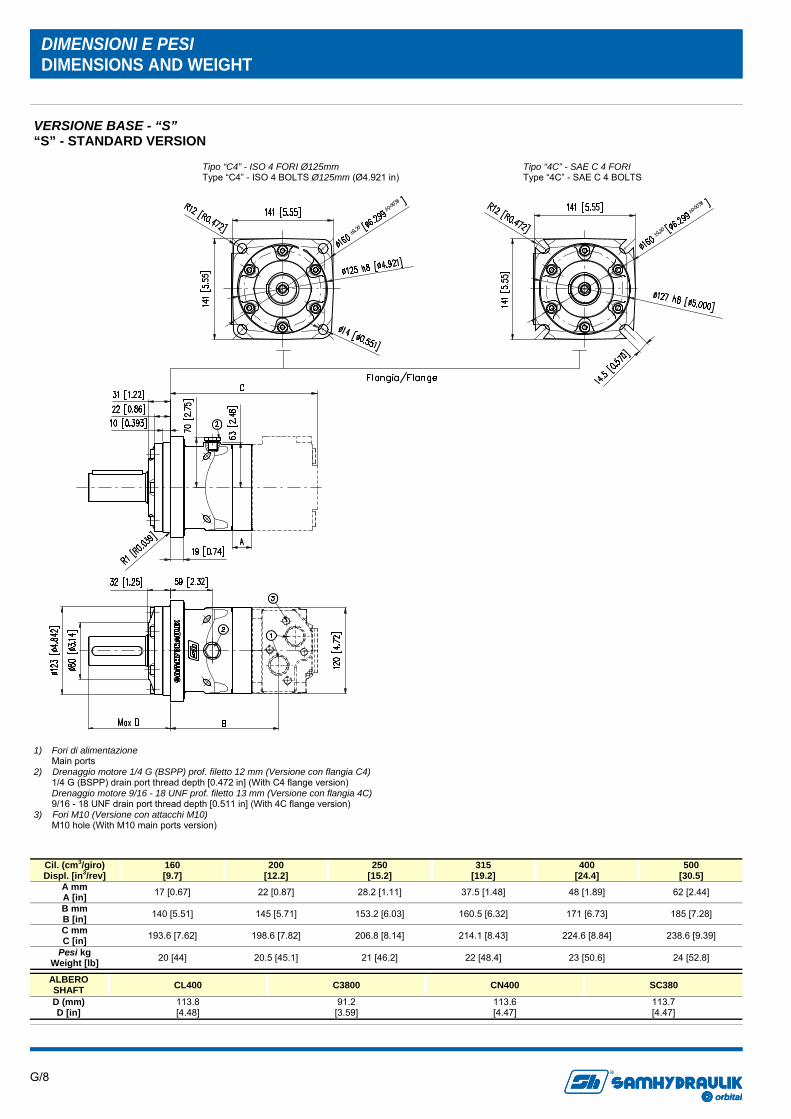
DIMENSIONI E PESI DIMENSIONS AND WEIGHT
ALBERO SHAFT CL400 C3800 CN400 SC380
D (mm) D [in]
113.8 [4.48]
91.2 [3.59]
113.6 [4.47]
113.7 [4.47]
VERSIONE BASE - “S” “S” - STANDARD VERSION
Tipo “C4” - ISO 4 FORI Ø125mm Type “C4” - ISO 4 BOLTS Ø125mm (Ø4.921 in)
Tipo “4C” - SAE C 4 FORI Type “4C” - SAE C 4 BOLTS
Cil. (cm3/giro) Displ. [in3/rev]
160 [9.7]
200 [12.2]
250 [15.2]
315 [19.2]
400 [24.4]
A mm A [in] 17 [0.67] 22 [0.87] 28.2 [1.11] 37.5 [1.48] 48 [1.89]
B mm B [in] 140 [5.51] 145 [5.71] 153.2 [6.03] 160.5 [6.32] 171 [6.73]
C mm C [in] 193.6 [7.62] 198.6 [7.82] 206.8 [8.14] 214.1 [8.43] 224.6 [8.84]
Pesi kg Weight [lb] 20 [44] 20.5 [45.1] 21 [46.2] 22 [48.4] 23 [50.6]
500 [30.5]
62 [2.44]
185 [7.28]
238.6 [9.39]
24 [52.8]
1) Fori di alimentazione Main ports 2) Drenaggio motore 1/4 G (BSPP) prof. filetto 12 mm (Versione con flangia C4) 1/4 G (BSPP) drain port thread depth [0.472 in] (With C4 flange version) Drenaggio motore 9/16 - 18 UNF prof. filetto 13 mm (Versione con flangia 4C) 9/16 - 18 UNF drain port thread depth [0.511 in] (With 4C flange version) 3) Fori M10 (Versione con attacchi M10) M10 hole (With M10 main ports version)

G/9 orbital
R
orbitalorbital
R
DIMENSIONI E PESI DIMENSIONS AND WEIGHT
VERSIONE BASE - “C” “C” - STANDARD VERSION
Cil. (cm3/giro) Displ. [in3/rev]
160 [9.7]
200 [12.2]
250 [15.2]
315 [19.2]
400 [24.4]
A mm A [in] 17 [0.67] 22 [0.87] 28.2 [1.11] 37.5 [1.48] 48 [1.89]
B mm B [in] 99.5 [3.92] 104.5 [4.11] 110.7 [4.36] 120 [4.72] 130.5 [5.14]
C mm C [in] 154 [6.06] 159 [6.26] 165.2 [6.50] 174.5 [6.87] 185 [7.28]
Pesi kg Weight [lb] 14.5 [31.9] 14.75 [32.5] 15 [33] 15.3 [33.8] 15.78 [34.8]
500 [30.5]
62 [2.44]
144.5 [5.69]
199 [7.83]
16.3 [36]
D mm D [in] 45 [1.77] 45 [1.77] 45 [1.77] 45 [1.77] 45 [1.77] 45 [1.77]
1) Fori di alimentazione Main ports 2) Drenaggio motore 1/4 G (BSPP) prof. filetto 14 mm (Versione con flangia C4) 1/4 G (BSPP) drain port thread depth [0.551 in] (With C4 flange version) Drenaggio motore 9/16 - 18 UNF prof. filetto 14 mm (Versione con flangia CS) 9/16 - 18 UNF drain port thread depth [0.551 in] (With CS flange version) 3) Fori M10 (Versione con attacchi M10) M10 hole (With M10 main ports version)
Tipo “C4-CS” - ISO 4 FORI Ø125mm Type “C4-CS” - ISO 4 BOLTS Ø125mm (Ø4.921 in)
G/10 orbital
R
orbitalorbital
R
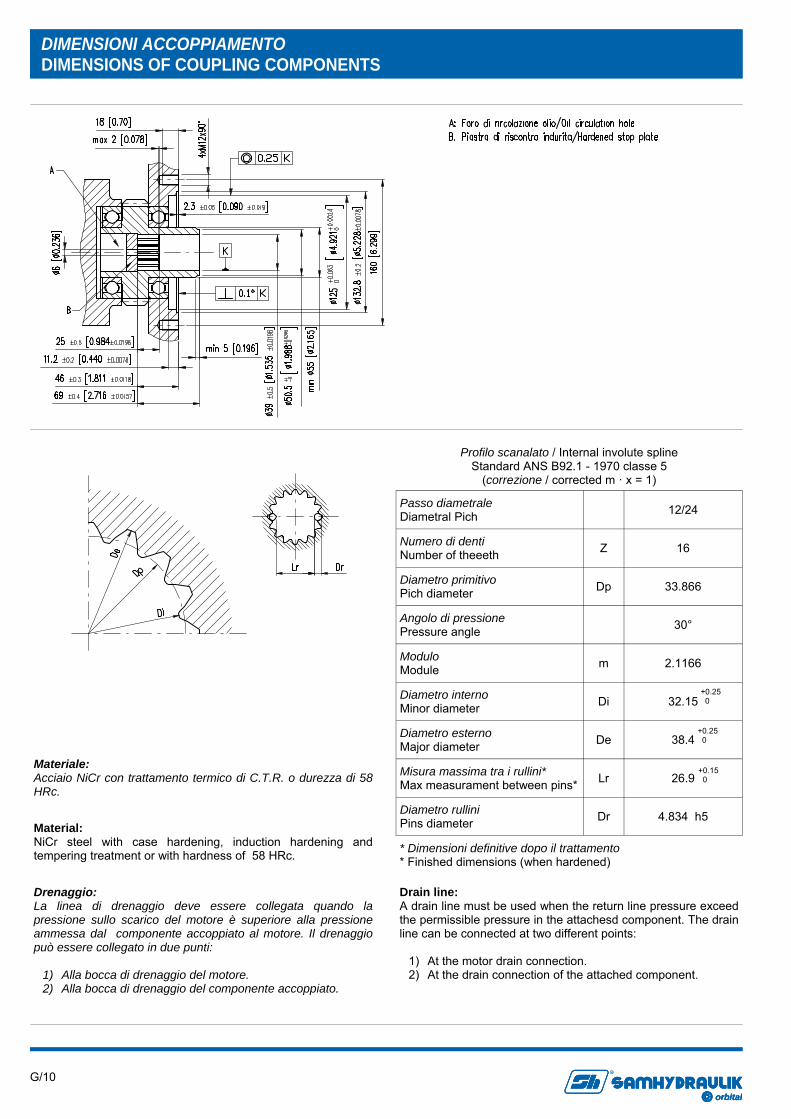
DIMENSIONI ACCOPPIAMENTO DIMENSIONS OF COUPLING COMPONENTS
Profilo scanalato / Internal involute spline Standard ANS B92.1 - 1970 classe 5
(correzione / corrected m · x = 1)
Passo diametrale Diametral Pich 12/24
Numero di denti Number of theeeth Z 16
Diametro primitivo Pich diameter Dp 33.866
Angolo di pressione Pressure angle 30°
Modulo Module m 2.1166
Diametro interno Minor diameter Di 32.15
Diametro esterno Major diameter De 38.4
Misura massima tra i rullini* Max measurament between pins* Lr 26.9
Diametro rullini Pins diameter Dr 4.834 h5
* Dimensioni definitive dopo il trattamento * Finished dimensions (when hardened)
+0.25 0
+0.25 0
+0.15 0
Materiale: Acciaio NiCr con trattamento termico di C.T.R. o durezza di 58 HRc.
Material: NiCr steel with case hardening, induction hardening and tempering treatment or with hardness of 58 HRc.
Drenaggio: La linea di drenaggio deve essere collegata quando la pressione sullo scarico del motore è superiore alla pressione ammessa dal componente accoppiato al motore. Il drenaggio può essere collegato in due punti:
1) Alla bocca di drenaggio del motore. 2) Alla bocca di drenaggio del componente accoppiato.
Drain line: A drain line must be used when the return line pressure exceed the permissible pressure in the attachesd component. The drain line can be connected at two different points:
1) At the motor drain connection. 2) At the drain connection of the attached component.
G/11 orbital
R
orbitalorbital
R
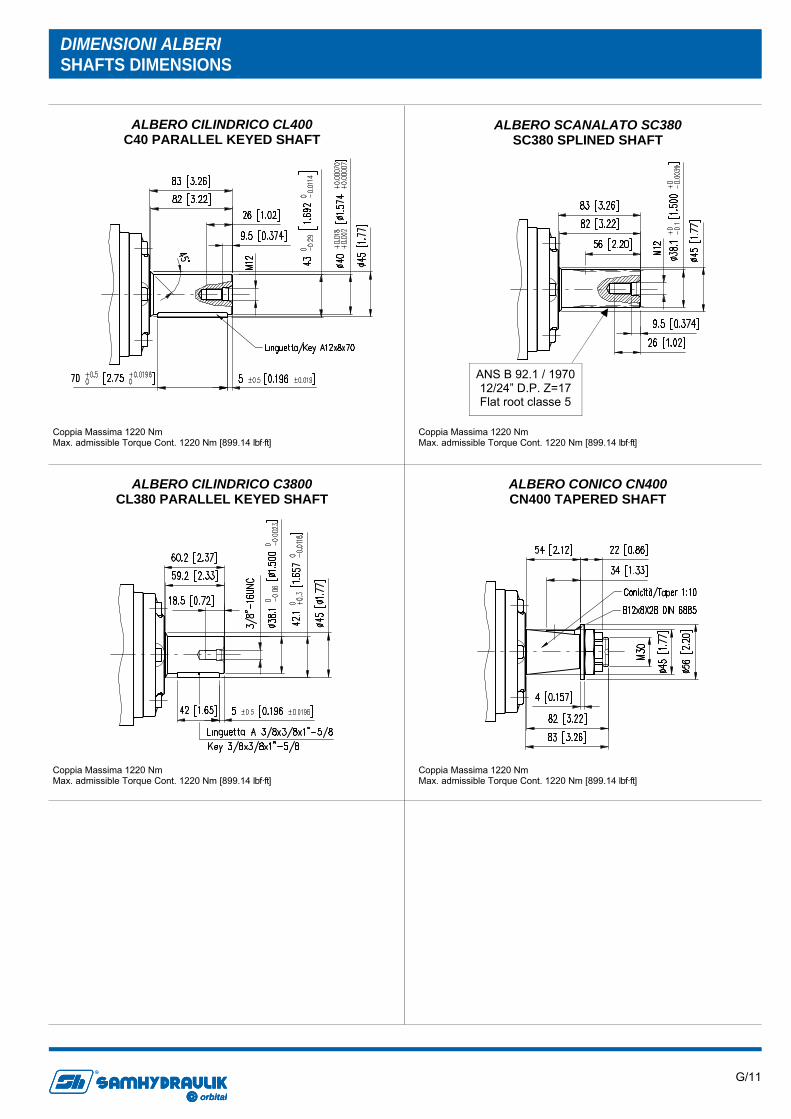
ALBERO CILINDRICO CL400 C40 PARALLEL KEYED SHAFT
ALBERO SCANALATO SC380 SC380 SPLINED SHAFT
ALBERO CONICO CN400 CN400 TAPERED SHAFT
ALBERO CILINDRICO C3800 CL380 PARALLEL KEYED SHAFT
DIMENSIONI ALBERI SHAFTS DIMENSIONS
ANS B 92.1 / 1970 12/24” D.P. Z=17 Flat root classe 5
Coppia Massima 1220 Nm Max. admissible Torque Cont. 1220 Nm [899.14 lbf·ft]
Coppia Massima 1220 Nm Max. admissible Torque Cont. 1220 Nm [899.14 lbf·ft]
Coppia Massima 1220 Nm Max. admissible Torque Cont. 1220 Nm [899.14 lbf·ft]
Coppia Massima 1220 Nm Max. admissible Torque Cont. 1220 Nm [899.14 lbf·ft]
G/12 orbital
R
orbitalorbital
R
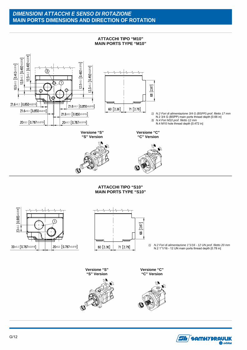
DIMENSIONI ATTACCHI E SENSO DI ROTAZIONE MAIN PORTS DIMENSIONS AND DIRECTION OF ROTATION
ATTACCHI TIPO “M10” MAIN PORTS TYPE “M10”
ATTACCHI TIPO “S10” MAIN PORTS TYPE “S10”
Versione “C” “C” Version
Versione “S” “S” Version
1) N.2 Fori di alimentazione 3/4 G (BSPP) prof. filetto 17 mm N.2 3/4 G (BSPP) main ports thread depth [0.66 in] 3) N.4 Fori M10 prof. filetto 12 mm N.4 M10 hole thread depth [0.472 in]
1) N.2 Fori di alimentazione 1”1/16 - 12 UN prof. filetto 20 mm N.2 1”1/16 - 12 UN main ports thread depth [0.78 in]
Versione “C” “C” Version
Versione “S” “S” Version
G/13 orbital
R
orbitalorbital
R
CARATTERISTICHE VERSIONE VERSION FEATURE
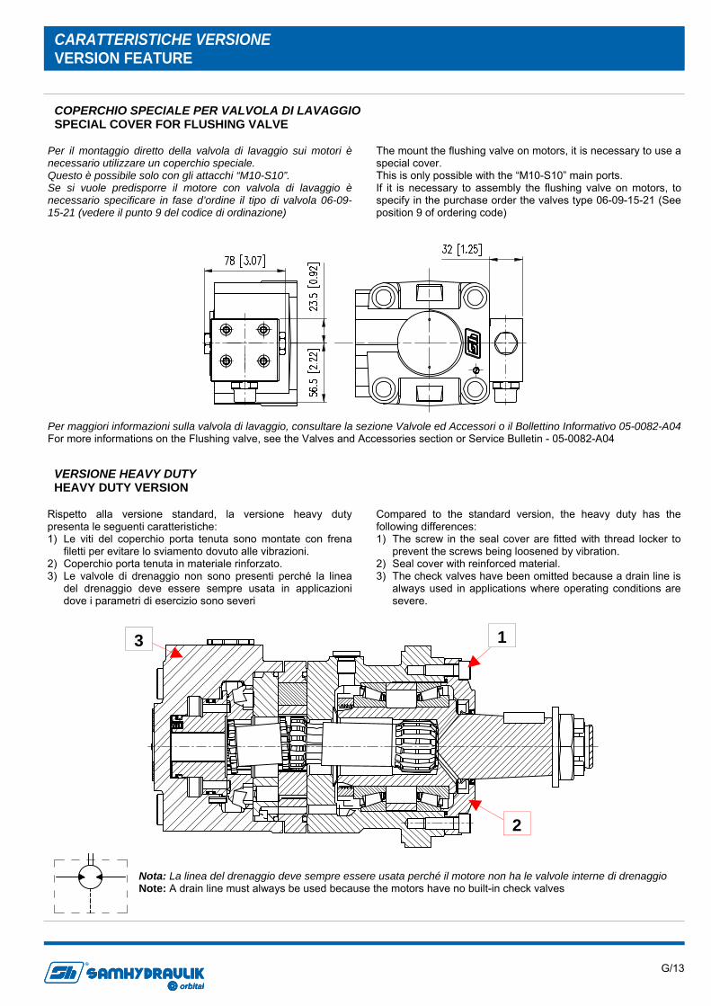
Per il montaggio diretto della valvola di lavaggio sui motori è necessario utilizzare un coperchio speciale. Questo è possibile solo con gli attacchi “M10-S10”. Se si vuole predisporre il motore con valvola di lavaggio è necessario specificare in fase d’ordine il tipo di valvola 06-09-15-21 (vedere il punto 9 del codice di ordinazione)
The mount the flushing valve on motors, it is necessary to use a special cover. This is only possible with the “M10-S10” main ports. If it is necessary to assembly the flushing valve on motors, to specify in the purchase order the valves type 06-09-15-21 (See position 9 of ordering code)
COPERCHIO SPECIALE PER VALVOLA DI LAVAGGIO SPECIAL COVER FOR FLUSHING VALVE
Per maggiori informazioni sulla valvola di lavaggio, consultare la sezione Valvole ed Accessori o il Bollettino Informativo 05-0082-A04 For more informations on the Flushing valve, see the Valves and Accessories section or Service Bulletin - 05-0082-A04
VERSIONE HEAVY DUTY HEAVY DUTY VERSION
Rispetto alla versione standard, la versione heavy duty presenta le seguenti caratteristiche: 1) Le viti del coperchio porta tenuta sono montate con frena
filetti per evitare lo sviamento dovuto alle vibrazioni. 2) Coperchio porta tenuta in materiale rinforzato. 3) Le valvole di drenaggio non sono presenti perché la linea
del drenaggio deve essere sempre usata in applicazioni dove i parametri di esercizio sono severi
Compared to the standard version, the heavy duty has the following differences: 1) The screw in the seal cover are fitted with thread locker to
prevent the screws being loosened by vibration. 2) Seal cover with reinforced material. 3) The check valves have been omitted because a drain line is
always used in applications where operating conditions are severe.
1
2
3
Nota: La linea del drenaggio deve sempre essere usata perché il motore non ha le valvole interne di drenaggio Note: A drain line must always be used because the motors have no built-in check valves

G/14 orbital
R
orbitalorbital
R
TACHIMETRO TACHOMETER
Numero d'impulsi per giro = 42 Principio di funzionamento induttivo Funzione di uscita PNP Tensione nominale 10-65 V d.c. Caricabilità massima 300 mA Frequenza massima 1200 Hz Campo di temperatura -25C +85C Grado di protezione IP 67
Number of pulses per revolution = 42 Inductive principle Ouput current PNP Voltage 10-65 V d.c. Max load 300 mA Max frequency 1200 Hz Temperature range -25C +85C Enclosure IP 67
Segnale in uscita Output signal
G/15 orbital
R
orbitalorbital
R
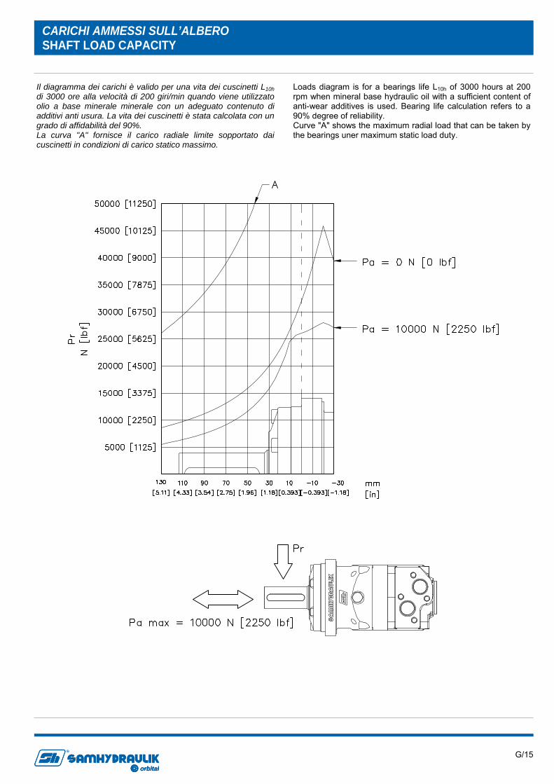
Il diagramma dei carichi è valido per una vita dei cuscinetti L10h di 3000 ore alla velocità di 200 giri/min quando viene utilizzato olio a base minerale minerale con un adeguato contenuto di additivi anti usura. La vita dei cuscinetti è stata calcolata con un grado di affidabilità del 90%. La curva "A" fornisce il carico radiale limite sopportato dai cuscinetti in condizioni di carico statico massimo.
Loads diagram is for a bearings life L10h of 3000 hours at 200 rpm when mineral base hydraulic oil with a sufficient content of anti-wear additives is used. Bearing life calculation refers to a 90% degree of reliability. Curve "A" shows the maximum radial load that can be taken by the bearings uner maximum static load duty.
CARICHI AMMESSI SULL’ALBERO SHAFT LOAD CAPACITY
G/16 orbital
R
orbitalorbital
R
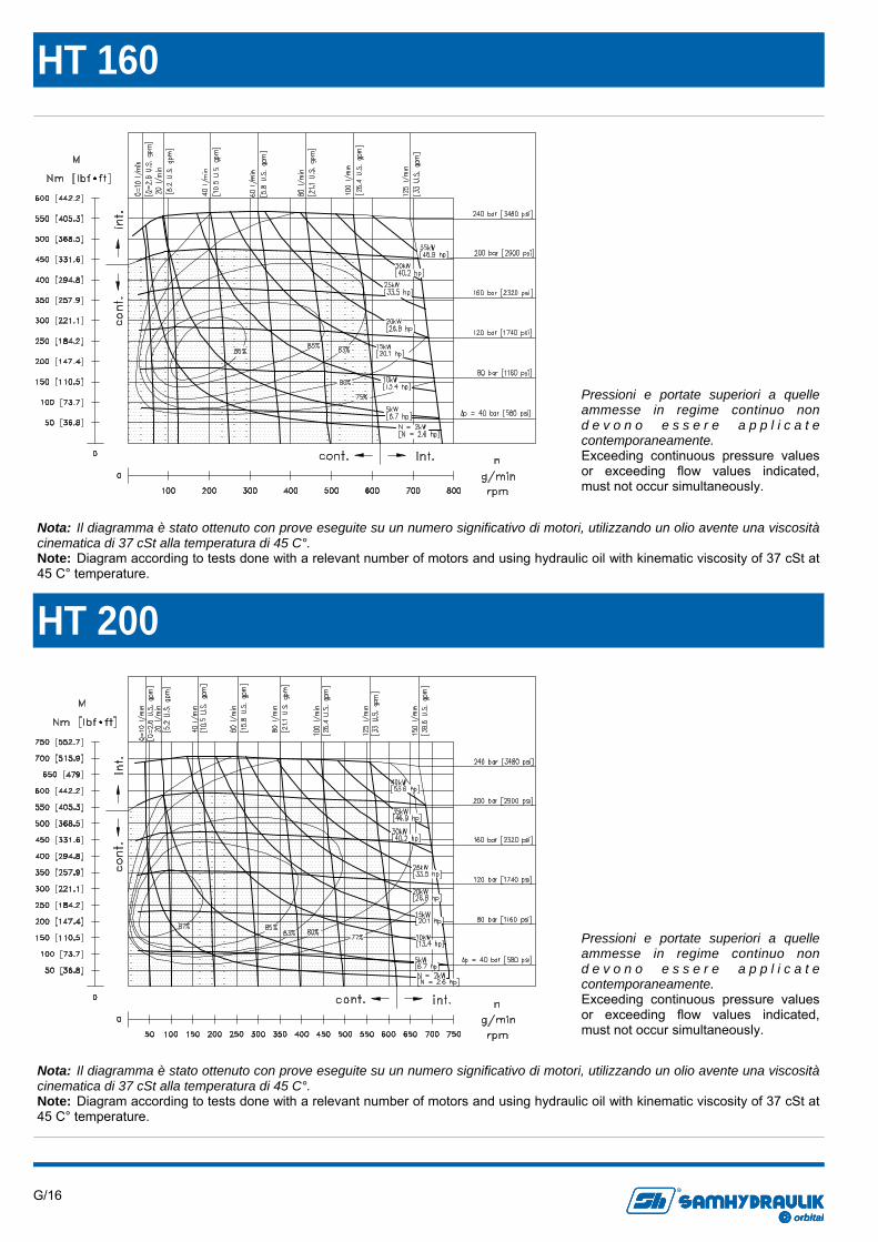
HT 160
HT 200
Pressioni e portate superiori a quelle ammesse in regime continuo non d e v o n o e s s e r e a p p l i c a t e contemporaneamente. Exceeding continuous pressure values or exceeding flow values indicated, must not occur simultaneously.
Pressioni e portate superiori a quelle ammesse in regime continuo non d e v o n o e s s e r e a p p l i c a t e contemporaneamente. Exceeding continuous pressure values or exceeding flow values indicated, must not occur simultaneously.
Nota: Il diagramma è stato ottenuto con prove eseguite su un numero significativo di motori, utilizzando un olio avente una viscosità cinematica di 37 cSt alla temperatura di 45 C°. Note: Diagram according to tests done with a relevant number of motors and using hydraulic oil with kinematic viscosity of 37 cSt at 45 C° temperature.
Nota: Il diagramma è stato ottenuto con prove eseguite su un numero significativo di motori, utilizzando un olio avente una viscosità cinematica di 37 cSt alla temperatura di 45 C°. Note: Diagram according to tests done with a relevant number of motors and using hydraulic oil with kinematic viscosity of 37 cSt at 45 C° temperature.
G/17 orbital
R
orbitalorbital
R
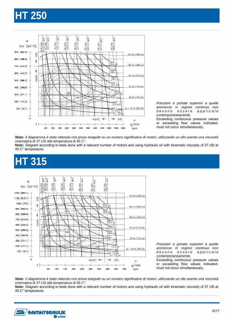
HT 315
HT 250
Pressioni e portate superiori a quelle ammesse in regime continuo non d e v o n o e s s e r e a p p l i c a t e contemporaneamente. Exceeding continuous pressure values or exceeding flow values indicated, must not occur simultaneously.
Pressioni e portate superiori a quelle ammesse in regime continuo non d e v o n o e s s e r e a p p l i c a t e contemporaneamente. Exceeding continuous pressure values or exceeding flow values indicated, must not occur simultaneously.
Nota: Il diagramma è stato ottenuto con prove eseguite su un numero significativo di motori, utilizzando un olio avente una viscosità cinematica di 37 cSt alla temperatura di 45 C°. Note: Diagram according to tests done with a relevant number of motors and using hydraulic oil with kinematic viscosity of 37 cSt at 45 C° temperature.
Nota: Il diagramma è stato ottenuto con prove eseguite su un numero significativo di motori, utilizzando un olio avente una viscosità cinematica di 37 cSt alla temperatura di 45 C°. Note: Diagram according to tests done with a relevant number of motors and using hydraulic oil with kinematic viscosity of 37 cSt at 45 C° temperature.
G/18 orbital
R
orbitalorbital
R
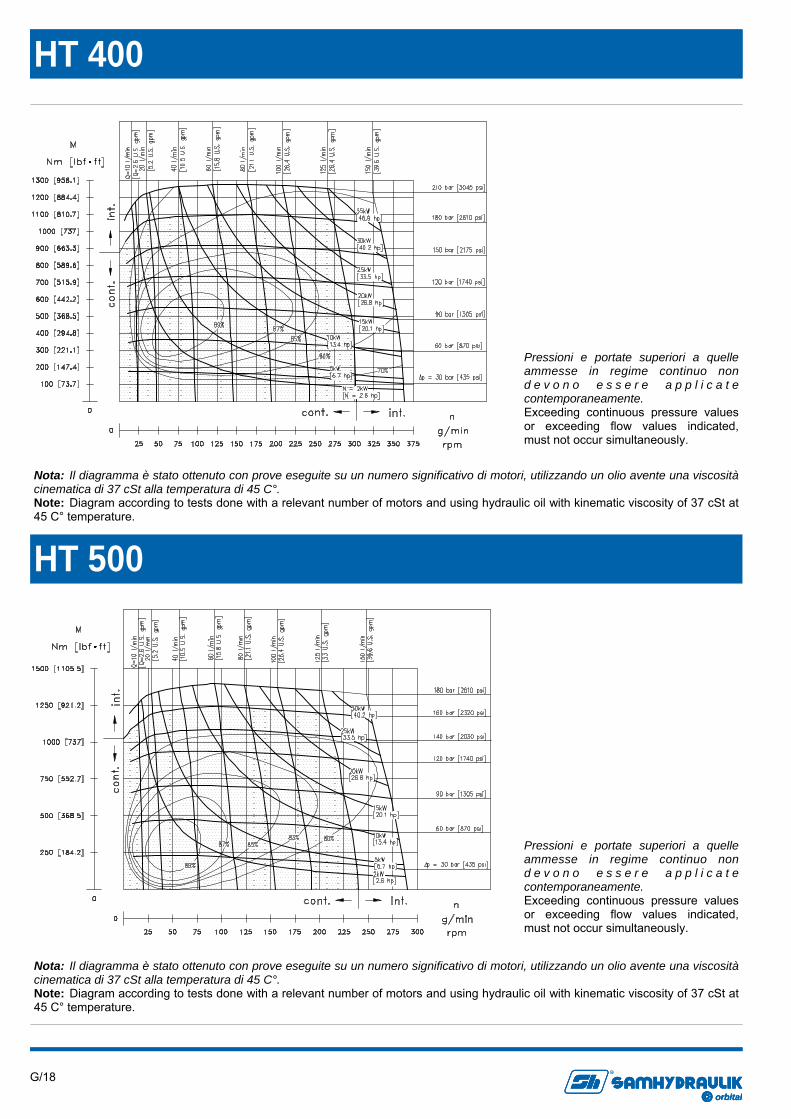
HT 500
HT 400
Pressioni e portate superiori a quelle ammesse in regime continuo non d e v o n o e s s e r e a p p l i c a t e contemporaneamente. Exceeding continuous pressure values or exceeding flow values indicated, must not occur simultaneously.
Pressioni e portate superiori a quelle ammesse in regime continuo non d e v o n o e s s e r e a p p l i c a t e contemporaneamente. Exceeding continuous pressure values or exceeding flow values indicated, must not occur simultaneously.
Nota: Il diagramma è stato ottenuto con prove eseguite su un numero significativo di motori, utilizzando un olio avente una viscosità cinematica di 37 cSt alla temperatura di 45 C°. Note: Diagram according to tests done with a relevant number of motors and using hydraulic oil with kinematic viscosity of 37 cSt at 45 C° temperature.
Nota: Il diagramma è stato ottenuto con prove eseguite su un numero significativo di motori, utilizzando un olio avente una viscosità cinematica di 37 cSt alla temperatura di 45 C°. Note: Diagram according to tests done with a relevant number of motors and using hydraulic oil with kinematic viscosity of 37 cSt at 45 C° temperature.
G/19 orbital
R
orbitalorbital
R
Informazioni sul prodotto Dati i continui sviluppi, le modifiche e le migliorie al prodotto, la S.AM Hydraulik Spa non sarà responsabile per eventuali informazioni che possano indurre in errore, od erronee, riportate da cataloghi, istruzioni, disegni, dati tecnici e altri dati forniti dalla S.A.M. Hydraulik Spa. Non sarà possibile basare alcun procedimento legale su tale materiale. Modifiche del prodotto. La S.A.M. Hydraulik Spa si riserva il diritto di variare i suoi prodotti, anche quelli già ordinati, senza notifica. Notice Due to the continuous product developments, modifications and improvements S.A.M. Hydraulik Spa will not be held responsible for any erroneous information or data that may lead to errors, indicated in catalogues, instructions, drawings, technical data and other data supplied by S.A.M. Hydraulik Spa. Therefore, legal actions cannot be based on such material. Product development. S.A.M. Hydraulik Spa reserves the right to make changes to its products, even for those already ordered, without notice.