
HMI030 Unità di visualizzazione remota Manuale d’uso ... · Remote visualization unit ... Lo...
14
2 ABB SACE HMI030 1SDH000573R0001 L9571 IT/EN HMI030 Unità di visualizzazione remota Manuale d’uso Remote visualization unit User manual
-
Upload
truongkiet -
Category
Documents
-
view
215 -
download
0
Transcript of HMI030 Unità di visualizzazione remota Manuale d’uso ... · Remote visualization unit ... Lo...

2
ABB SACE HMI030 1SDH000573R0001 L9571 IT/EN
HMI030
Unità di visualizzazione remotaManuale d’uso
Remote visualization unitUser manual
1
ABB SACE HMI030 1SDH000573R0001 L9571 1/13
SOMMARIO1. Premessa . . . . . . . . . . . . . . . . . . . . . . 2
2. Panoramica HMI030 . . . . . . . . . . . . . . 42.1 Vista Frontale . . . . . . . . . . . . . . . . . . . . . . 42.2 Vista Posteriore . . . . . . . . . . . . . . . . . . . . 4
3. Settaggi preliminari . . . . . . . . . . . . . . 5
4. Albero dei menù . . . . . . . . . . . . . . . . . 64.1 Modalità Amperometro . . . . . . . . . . . . . . . 64.2 Modalità Voltmetro . . . . . . . . . . . . . . . . . . 74.3 Modalità Wattmetro . . . . . . . . . . . . . . . . . 84.4 Modalità Custom . . . . . . . . . . . . . . . . . . . 9
5. Messaggi di errore . . . . . . . . . . . . . . 105.1 Segnalazioni LED Alarm . . . . . . . . . . . . 10
6. Caratteristiche tecniche . . . . . . . . . 116.1 Caratteristiche elettriche . . . . . . . . . . . . 11
6.1.1 Alimentazione ausiliaria . . . . . . . . . . . . . . . .116.2 Caratteristiche meccaniche . . . . . . . . . . 116.3 Condizioni ambientali . . . . . . . . . . . . . . . 11
7. Fissaggio . . . . . . . . . . . . . . . . . . . . . . 127.1 Dimensioni . . . . . . . . . . . . . . . . . . . . . . . 127.2 Fissaggio sulla portella . . . . . . . . . . . . . . 12
8. Schema elettrico . . . . . . . . . . . . . . . 13
CONTENTS1. Introduction . . . . . . . . . . . . . . . . . . . . 2
2. Overview HMI030 . . . . . . . . . . . . . . . . 42.1 Front View . . . . . . . . . . . . . . . . . . . . . . . .42.2 Rear View . . . . . . . . . . . . . . . . . . . . . . . . .4
3. Preliminary settings . . . . . . . . . . . . . . 5
4. Menu tree . . . . . . . . . . . . . . . . . . . . . . 64.1 Ammeter mode . . . . . . . . . . . . . . . . . . . . .64.2 Voltmeter mode . . . . . . . . . . . . . . . . . . . .74.3 Wattmeter mode . . . . . . . . . . . . . . . . . . . .84.4 Custom mode . . . . . . . . . . . . . . . . . . . . . .9
5. Error messages . . . . . . . . . . . . . . . . . 105.1 LED Alarm signallings . . . . . . . . . . . . . .10
6. Technical characteristics . . . . . . . . 116.1 Electrical characteristics . . . . . . . . . . . . .11
6.1.1 Auxiliary power supply . . . . . . . . . . . . . . . . 116.2 Mechanical characteristics . . . . . . . . . . .116.3 Environment conditions . . . . . . . . . . . . .11
7. Installation . . . . . . . . . . . . . . . . . . . . 127.1 Dimensions . . . . . . . . . . . . . . . . . . . . . . .127.2 Installation on the switchgear panel . . . .12
8. Circuit diagram . . . . . . . . . . . . . . . . . 13
13
ABB SACE HMI030 1SDH000573R0001 L9571 2/13
1. IntroductionHMI030 is a remote visualization unit for electronic relays or trip units from the New Emax, Emax DC, Tmax, T7/X1, and Tmax XT series.
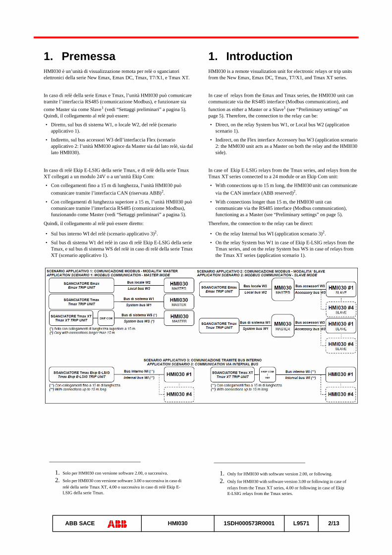
In case of relays from the Emax and Tmax series, the HMI030 unit can communicate via the RS485 interface (Modbus communication), and function as either a Master or a Slave1 (see “Preliminary settings” on page 5). Therefore, the connection to the relay can be:
• Direct, on the relay System bus W1, or Local bus W2 (application scenario 1).
• Indirect, on the Flex interface Accessory bus W3 (application scenario 2: the MM030 unit acts as a Master on both the relay and the HMI030 side).
In case of Ekip E-LSIG relays from the Tmax series, and relays from the Tmax XT series connected to a 24 module or an Ekip Com unit:
• With connections up to 15 m long, the HMI030 unit can communicate via the CAN interface (ABB reserved)2.
• With connections longer than 15 m, the HMI030 unit can communicate via the RS485 interface (Modbus communication), functioning as a Master (see “Preliminary settings” on page 5).
Therefore, the connection to the relay can be direct:
• On the relay Internal bus WI (application scenario 3)2.
• On the relay System bus W1 in case of Ekip E-LSIG relays from the Tmax series, and on the relay System bus WS in case of relays from the Tmax XT series (application scenario 1).
1. Only for HMI030 with software version 2.00, or following.
2. Only for HMI030 with software version 3.00 or following in case of relays from the Tmax XT series, 4.00 or following in case of Ekip E-LSIG relays from the Tmax series.
1. PremessaHMI030 è un’unità di visualizzazione remota per relè o sganciatori elettronici della serie New Emax, Emax DC, Tmax, T7/X1, e Tmax XT.
In caso di relè della serie Emax e Tmax, l’unità HMI030 può comunicare tramite l’interfaccia RS485 (comunicazione Modbus), e funzionare sia come Master sia come Slave1 (vedi “Settaggi preliminari” a pagina 5). Quindi, il collegamento al relè può essere:
• Diretto, sul bus di sistema W1, o locale W2, del relè (scenario applicativo 1).
• Indiretto, sul bus accessori W3 dell’interfaccia Flex (scenario applicativo 2: l’unità MM030 agisce da Master sia dal lato relè, sia dal lato HMI030).
In caso di relè Ekip E-LSIG della serie Tmax, e di relè della serie Tmax XT collegati a un modulo 24V o a un’unità Ekip Com:
• Con collegamenti fino a 15 m di lunghezza, l’unità HMI030 può comunicare tramite l’interfaccia CAN (riservata ABB)2.
• Con collegamenti di lunghezza superiore a 15 m, l’unità HMI030 può comunicare tramite l’interfaccia RS485 (comunicazione Modbus), funzionando come Master (vedi “Settaggi preliminari” a pagina 5).
Quindi, il collegamento al relè può essere diretto:
• Sul bus interno WI del relè (scenario applicativo 3)2.
• Sul bus di sistema W1 del relè in caso di relè Ekip E-LSIG della serie Tmax, e sul bus di sistema WS del relè in caso di relè della serie Tmax XT (scenario applicativo 1).
1. Solo per HMI030 con versione software 2.00, o successiva.
2. Solo per HMI030 con versione software 3.00 o successiva in caso di relè della serie Tmax XT, 4.00 o successiva in caso di relè Ekip E-LSIG della serie Tmax.

13
ABB SACE HMI030 1SDH000573R0001 L9571 3/13
On the HMI030 unit, the RS485 and CAN interfaces can’t be used at the same time. Therefore, it’s not possible to have at the same time the Modbus communication (application scenario 1 or 2), and the communication on the Internal bus WI (application scenario 3).
In the case of the application scenarios 2 and 3, up to four HMI030 units can be connected to the same bus. In case of more HMI030 units connected to the same bus, the HMI030 units must operate in different modes (Ammeter, Voltmeter, etc..., see paragraph 3).
The following table sums up the variuos application scenarios, and the relating connection buses between the devices:
1. In case of communicatione via the Internal Bus WI, the HMI030 unit must be configured in Master mode (see “Preliminary settings” on page 5).
2. Only with connections longer than 15 m. With connections up to 15 m, the communication via the Internal bus WI is recommended.
See also the circuit diagram on page 13.
In case of use of the System Bus W1 (PR222DS/PD and PR223DS/EF relays, and Tmax Ekip E-LSIG relay with connections longer than 15 m), or WS (Ekip LSI LSIG E-LSIG and M-LRIU relays, with connections longer than 15 m), the following relay settings are necessary:
• Address: 247
• Baud rate: 19200
• Parity: EVEN
• Stop bit(s): 1
The maximum lenght recommended for the System buses W1 and WS, and the Accessory bus W3, is 300 m.
The maximum lenght recommended for the Local bus W2 depends on the relay connected (in case of the PR12x relays, it’s 15 m).
The maximum lenght recommended for the Internal bus WI is 15 m.
The connection must be realized with Belden 3105A cables type, or equivalent, that’s with: twisted pair cables, shielded, and provided with a characteristic impedence equal to 120 Ohm. The cables shield must be linked to earth on one connection side.
Sull’unità HMI030, le interfacce RS485 e CAN non possono essere usate contemporaneamente. Quindi, non è possibile avere contemporaneamente la comunicazione Modbus (scenario applicativo 1 o 2), e la comunicazione sul bus interno WI (scenario applicativo 3).
Nel caso degli scenari applicativi 2 e 3, fino a quattro unità HMI030 possono essere collegate allo stesso bus. In caso di collegamento di più unità HMI030 allo stesso bus, le unità HMI030 devono operare in modalità diversa (Amperometro, Voltmetro, ecc..., vedi paragrafo 3).
La seguente tabella riassume i vari scenari applicativi, e i relativi bus di collegamento tra i dispositivi:
1. In caso di comunicazione tramite il bus interno WI, l’unità HMI030 deve essere configurata in modalità Master (vedi “Settaggi prelimi-nari” a pagina 5).
2. Solo con collegamenti di lunghezza superiore a 15 m. Con collega-menti fino a 15 m, è raccomandata la comunicazione tramite il bus interno WI.
Vedi anche lo schema elettrico a pagina 13.
In caso di uso del bus di sistema W1 (relè PR222DS/PD e PR223DS/EF, e Tmax Ekip E-LSIG con collegamenti di lunghezza superiore a 15 m), o WS (relè Ekip LSI LSIG E-LSIG ed M-LRIU, con collegamenti di lunghezza superiore a 15 m), sono necessarie le seguenti impostazioni del relè:
• Indirzzo: 247
• Velocità: 19200
• Parità: PARI
• Bit di stop: 1
La lunghezza massima raccomandata per i bus di sistema W1 e WS, e il bus accessori W3, è di 300 m.
La lunghezza massima raccomandata per il bus locale W2 dipende dal relè collegato (nel caso dei relè PR12x, è di 15 m).
La lunghezza massima raccomandata per il bus interno WI è di 15 m.
Il collegamento deve essere realizzato con cavi di tipo Belden 3105A, o equivalente, cioè con: coppia di cavi attorcigliati, schermata, e dotata di un’impedenza caratteristica pari a 120 Ohm. Lo schermo dei cavi deve essere connesso a terra da un lato del collegamento.
MASTERSLAVE
HMI030 MM030
PR121/PPR331/P
Bus locale W2Local bus W2
Bus locale W2Local bus W2
PR122/P, PR123/PPR332/P, PR333/PPR122/DC, PR123/DC
Bus locale W2Local bus W2
Bus locale W2Local bus W2
PR222DS/PDPR223DS/EF
Bus di sistema W1System bus W1
Bus di sistema W1System bus W1
Tmax Ekip E-LSIG Bus interno WI1, o bus di sistema W12
Internal bus WI1, or System bus W12
Bus di sistema W1System bus W1
Ekip LSI, Ekip LSIG,Ekip E-LSIG (Tmax XT),Ekip M-LRIU
Bus interno WI1, o bus di sistema WS2
Internal bus WI1, or System bus WS2
Non consentitoNot allowed
HMI030 Non consentitoNot allowed
Bus accessori W3Accessory bus W3
13
ABB SACE HMI030 1SDH000573R0001 L9571 4/13
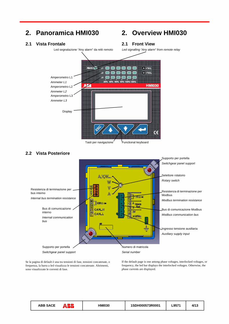
2. Overview HMI0302.1 Front View
2.2 Rear View
If the default page is one among phase voltages, interlocked voltages, or frequency, the led bar displays the interlocked voltages. Otherwise, the phase currents are displayed.
2. Panoramica HMI0302.1 Vista Frontale
2.2 Vista Posteriore
Se la pagina di default è una tra tensioni di fase, tensioni concatenate, o frequenza, la barra a led visualizza le tensioni concatenate. Altrimenti, sono visualizzate le correnti di fase.
Led segnalazione “Any alarm” da relè remoto Led signalling “Any alarm” from remote relay
Amperometro L3Ammeter L3
Amperometro L1Ammeter L1Amperometro L2Ammeter L2
Tasti per navigazione Functional keyboard
Display
Resistenza di terminazione per bus interno
Internal bus termination resistance
Resistenza di terminazione per Modbus
Modbus termination resistance
Ingresso tensione ausiliaria
Auxiliary supply input
Bus di comunicazione interno
Internal communication bus
Bus di comunicazione Modbus
Modbus communication bus
Selettore rotatorio
Rotary switch
Supporto per portella
Switchgear panel support
Supporto per portella
Switchgear panel support
Numero di matricola
Serial number
13
ABB SACE HMI030 1SDH000573R0001 L9571 5/13
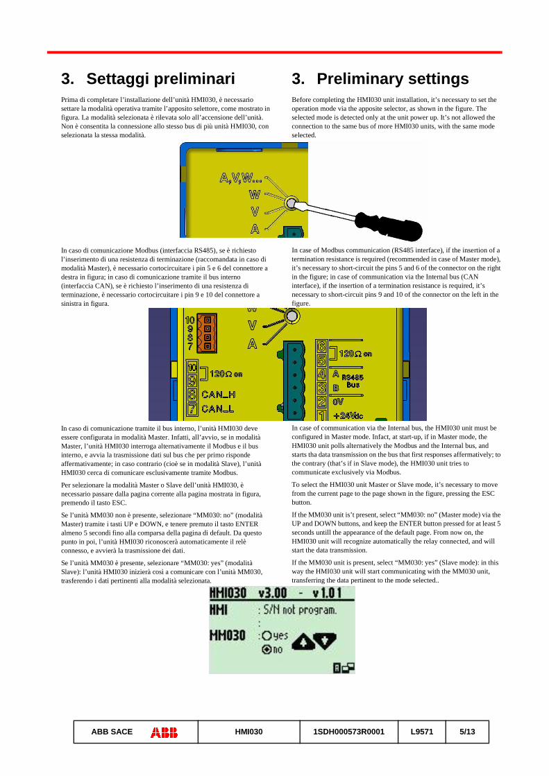
3. Preliminary settingsBefore completing the HMI030 unit installation, it’s necessary to set the operation mode via the apposite selector, as shown in the figure. The selected mode is detected only at the unit power up. It’s not allowed the connection to the same bus of more HMI030 units, with the same mode selected.
In case of Modbus communication (RS485 interface), if the insertion of a termination resistance is required (recommended in case of Master mode), it’s necessary to short-circuit the pins 5 and 6 of the connector on the right in the figure; in case of communication via the Internal bus (CAN interface), if the insertion of a termination resistance is required, it’s necessary to short-circuit pins 9 and 10 of the connector on the left in the figure.
In case of communication via the Internal bus, the HMI030 unit must be configured in Master mode. Infact, at start-up, if in Master mode, the HMI030 unit polls alternatively the Modbus and the Internal bus, and starts tha data transmission on the bus that first responses affermatively; to the contrary (that’s if in Slave mode), the HMI030 unit tries to communicate exclusively via Modbus.
To select the HMI030 unit Master or Slave mode, it’s necessary to move from the current page to the page shown in the figure, pressing the ESC button.
If the MM030 unit is’t present, select “MM030: no” (Master mode) via the UP and DOWN buttons, and keep the ENTER button pressed for at least 5 seconds untill the appearance of the default page. From now on, the HMI030 unit will recognize automatically the relay connected, and will start the data transmission.
If the MM030 unit is present, select “MM030: yes” (Slave mode): in this way the HMI030 unit will start communicating with the MM030 unit, transferring the data pertinent to the mode selected..
3. Settaggi preliminariPrima di completare l’installazione dell’unità HMI030, è necessario settare la modalità operativa tramite l’apposito selettore, come mostrato in figura. La modalità selezionata è rilevata solo all’accensione dell’unità. Non è consentita la connessione allo stesso bus di più unità HMI030, con selezionata la stessa modalità.
In caso di comunicazione Modbus (interfaccia RS485), se è richiesto l’inserimento di una resistenza di terminazione (raccomandata in caso di modalità Master), è necessario cortocircuitare i pin 5 e 6 del connettore a destra in figura; in caso di comunicazione tramite il bus interno (interfaccia CAN), se è richiesto l’inserimento di una resistenza di terminazione, è necessario cortocircuitare i pin 9 e 10 del connettore a sinistra in figura.
In caso di comunicazione tramite il bus interno, l’unità HMI030 deve essere configurata in modalità Master. Infatti, all’avvio, se in modalità Master, l’unità HMI030 interroga alternativamente il Modbus e il bus interno, e avvia la trasmissione dati sul bus che per primo risponde affermativamente; in caso contrario (cioè se in modalità Slave), l’unità HMI030 cerca di comunicare esclusivamente tramite Modbus.
Per selezionare la modalità Master o Slave dell’unità HMI030, è necessario passare dalla pagina corrente alla pagina mostrata in figura, premendo il tasto ESC.
Se l’unità MM030 non è presente, selezionare “MM030: no” (modalità Master) tramite i tasti UP e DOWN, e tenere premuto il tasto ENTER almeno 5 secondi fino alla comparsa della pagina di default. Da questo punto in poi, l’unità HMI030 riconoscerà automaticamente il relè connesso, e avvierà la trasmissione dei dati.
Se l’unità MM030 è presente, selezionare “MM030: yes” (modalità Slave): l’unità HMI030 inizierà così a comunicare con l’unità MM030, trasferendo i dati pertinenti alla modalità selezionata.

13
ABB SACE HMI030 1SDH000573R0001 L9571 6/13
4. Menu treeThe operation modes selectable on the HMI030 unit rear side are:
• Ammeter
• Voltmeter
• Wattmeter
• Custom
Once the mode is selected, the default page will appear. To change the default page: display the wanted page, push the ESC button, and keep the ENTER button pressed until the appearance of the wanted page.
The following icones appear on the pages displayed:
1. Communication ongoing2. LED bars content (voltages or currents, depending on the default
page)3. Default page4. Circuit Breaker status (open, closed, undefined, tripped)5. Setting in progress6. LED error7. Incongruency between the selector position and the freezed one
The HMI030 unit provides currents, voltages, and other measures (active powers, reactive powers, etc...), only if these information are available in the relay connected.
4.1 Ammeter mode
Pages displayed
Display of the maximum currents (and phases) belonging to the last acquisition (for the relays that support this option, and in case of Modbus communication only for the HMI030 unit operating in Master mode).
4. Albero dei menùLe modalità selezionabili sul retro dell’unità HMI030 sono:
• Amperometro
• Voltmetro
• Wattmetro
• Custom
Una volta selezionata la modalità, comparirà la pagina di default. Per cambiare la pagina di default: visualizzare la pagina desiderata, premere il pulsante ESC, e tenere premuto il pulsante ENTER fino alla comparsa della pagina desiderata.
Sulle pagine visualizzate compaiono le seguenti icone:
1. Comunicazione attiva2. Contenuto delle barre dei LED (tensioni o correnti, dipendentemente
dalla pagina di default)3. Pagina di default4. Stato interruttore (aperto, chiuso, indefinito, scattato)5. Configurazione in corso6. Errore dei LED7. Posizione del selettore incongruente con quella memorizzata
L’unità HMI030 fornisce correnti, tensioni, e altre misure (potenze attive, potenze reattive, ecc...), solo se queste informazioni sono disponibili nel relè connesso.
4.1 Modalità Amperometro
Pagine visualizzate
Visualizzazione delle massime correnti (e fasi) dell’ultima acquisizione (per i relè che supportano questa opzione, e in caso di comunicazione Modbus solo per l’unità HMI030 in modalità Master).
1.
2.
3.
4.
5.
6.
7.
13
ABB SACE HMI030 1SDH000573R0001 L9571 7/13
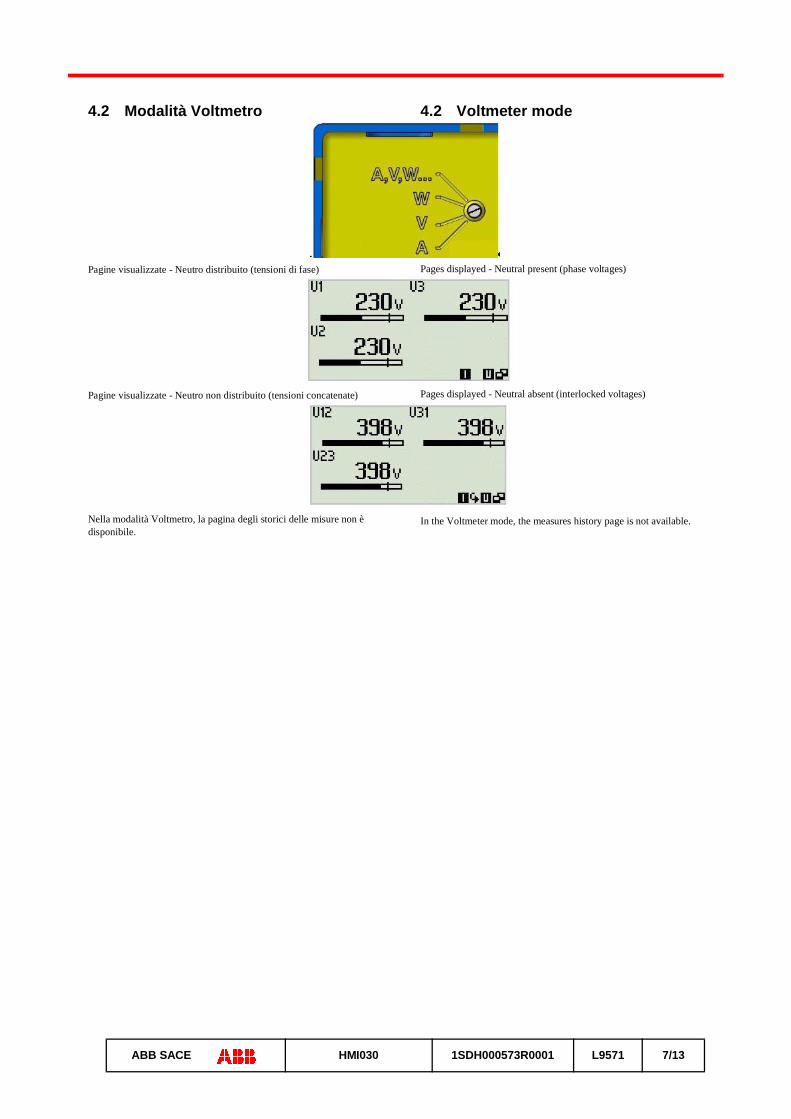
4.2 Voltmeter mode
Pages displayed - Neutral present (phase voltages)
Pages displayed - Neutral absent (interlocked voltages)
In the Voltmeter mode, the measures history page is not available.
4.2 Modalità Voltmetro
Pagine visualizzate - Neutro distribuito (tensioni di fase)
Pagine visualizzate - Neutro non distribuito (tensioni concatenate)
Nella modalità Voltmetro, la pagina degli storici delle misure non è disponibile.

13
ABB SACE HMI030 1SDH000573R0001 L9571 8/13
4.3 Wattmeter mode
Pages displayed - Neutral present
Pages displayed - Neutral absent
4.3 Modalità Wattmetro
Pagine visualizzate - Neutro distribuito
Pagine visualizzate - Neutro non distribuito
13
ABB SACE HMI030 1SDH000573R0001 L9571 9/13
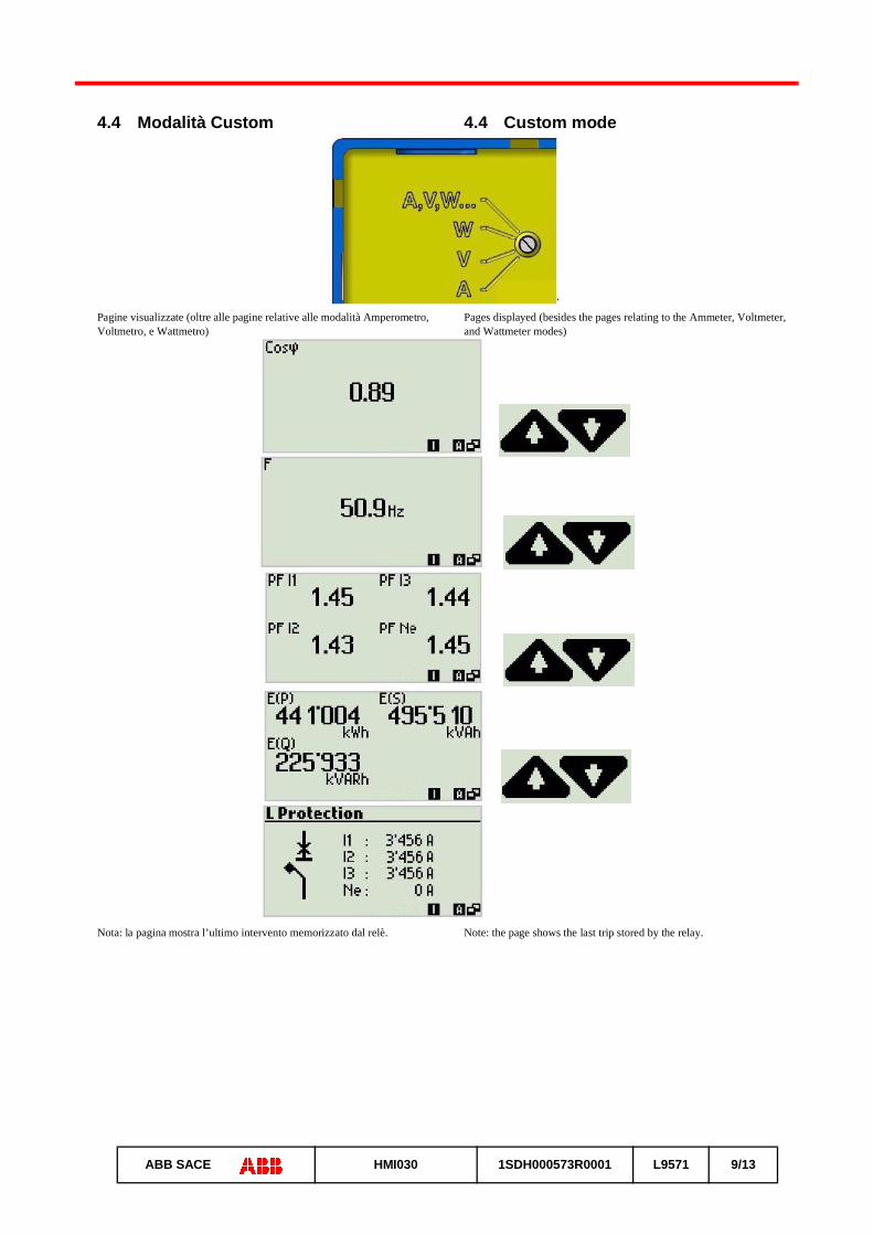
4.4 Custom mode
Pages displayed (besides the pages relating to the Ammeter, Voltmeter, and Wattmeter modes)
Note: the page shows the last trip stored by the relay.
4.4 Modalità Custom
Pagine visualizzate (oltre alle pagine relative alle modalità Amperometro, Voltmetro, e Wattmetro)
Nota: la pagina mostra l’ultimo intervento memorizzato dal relè.
13
ABB SACE HMI030 1SDH000573R0001 L9571 10/13
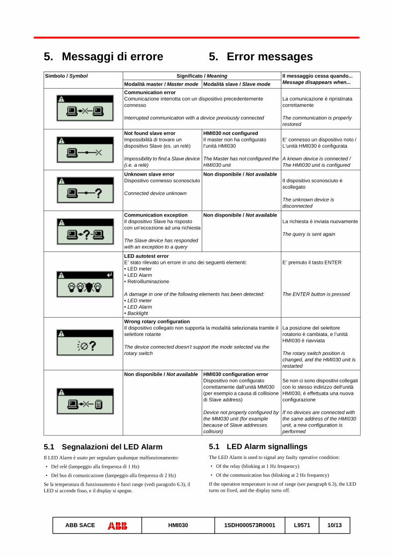
5. Error messages
5.1 LED Alarm signallingsThe LED Alarm is used to signal any faulty operative condition:
• Of the relay (blinking at 1 Hz frequency)
• Of the communication bus (blinking at 2 Hz frequency)
If the operation temperature is out of range (see paragraph 6.3), the LED turns on fixed, and the display turns off.
5. Messaggi di errore
5.1 Segnalazioni del LED AlarmIl LED Alarm è usato per segnalare qualunque malfunzionamento:
• Del relè (lampeggio alla frequenza di 1 Hz)
• Del bus di comunicazione (lampeggio alla frequenza di 2 Hz)
Se la temperatura di funzionamento è fuori range (vedi paragrafo 6.3), il LED si accende fisso, e il display si spegne.
Simbolo / Symbol Significato / Meaning Il messaggio cessa quando...Message disappears when...Modalità master / Master mode Modalità slave / Slave mode
Communication errorComunicazione interrotta con un dispositivo precedentemente connesso
Interrupted communication with a device previously connected
La comunicazione è ripristinata correttamente
The communication is properly restored
Not found slave errorImpossibilità di trovare un dispositivo Slave (es. un relè)
Impossibility to find a Slave device (i.e. a relè)
HMI030 not configuredIl master non ha configurato l’unità HMI030
The Master has not configured the HMI030 unit
E’ connesso un dispositivo noto / L’unità HMI030 è configurata
A known device is connected / The HMI030 unit is configured
Unknown slave errorDispositivo connesso sconosciuto
Connected device unknown
Non disponibile / Not availableIl dispositivo sconosciuto è scollegato
The unknown device is disconnected
Communication exception Il dispositivo Slave ha risposto con un’eccezione ad una richiesta
The Slave device has responded with an exception to a query
Non disponibile / Not availableLa richiesta è inviata nuovamente
The query is sent again
LED autotest errorE’ stato rilevato un errore in uno dei seguenti elementi:• LED meter• LED Alarm• Retroilluminazione
A damage in one of the following elements has been detected:• LED meter• LED Alarm• Backlight
E’ premuto il tasto ENTER
The ENTER button is pressed
Wrong rotary configurationIl dispositivo collegato non supporta la modalità selezionata tramite il selettore rotante
The device connected doesn’t support the mode selected via the rotary switch
La posizione del selettore rotatorio è cambiata, e l’unità HMI030 è riavviata
The rotary switch position is changed, and the HMI030 unit is restarted
Non disponibile / Not available HMI030 configuration errorDispositivo non configurato correttamente dall’unità MM030 (per esempio a causa di collisione di Slave address)
Device not properly configured by the MM030 unit (for example because of Slave addresses collision)
Se non ci sono dispositivi collegati con lo stesso indirizzo dell’unità HMI030, è effettuata una nuova configurazione
If no devices are connected with the same address of the HMI030 unit, a new configuration is performed
13
ABB SACE HMI030 1SDH000573R0001 L9571 11/13
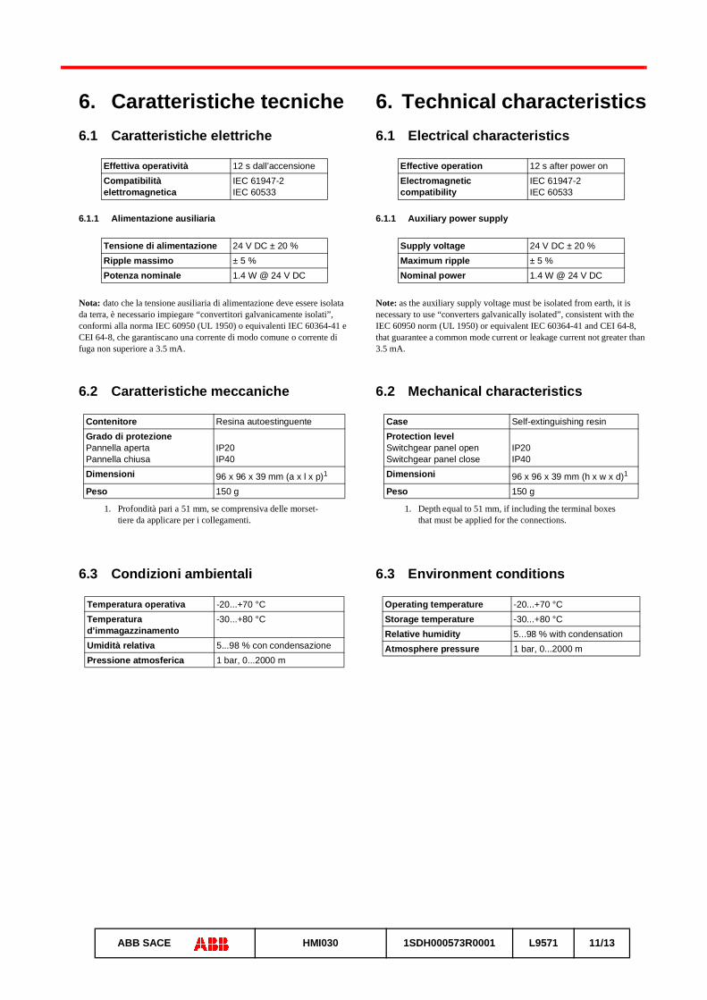
6. Technical characteristics6.1 Electrical characteristics
6.1.1 Auxiliary power supply
Note: as the auxiliary supply voltage must be isolated from earth, it is necessary to use “converters galvanically isolated”, consistent with the IEC 60950 norm (UL 1950) or equivalent IEC 60364-41 and CEI 64-8, that guarantee a common mode current or leakage current not greater than 3.5 mA.
6.2 Mechanical characteristics
6.3 Environment conditions
Effective operation 12 s after power onElectromagnetic compatibility
IEC 61947-2IEC 60533
Supply voltage 24 V DC ± 20 %Maximum ripple ± 5 %Nominal power 1.4 W @ 24 V DC
Case Self-extinguishing resinProtection levelSwitchgear panel openSwitchgear panel close
IP20IP40
Dimensioni 96 x 96 x 39 mm (h x w x d)1
1. Depth equal to 51 mm, if including the terminal boxes that must be applied for the connections.
Peso 150 g
Operating temperature -20...+70 °CStorage temperature -30...+80 °CRelative humidity 5...98 % with condensationAtmosphere pressure 1 bar, 0...2000 m
6. Caratteristiche tecniche6.1 Caratteristiche elettriche
6.1.1 Alimentazione ausiliaria
Nota: dato che la tensione ausiliaria di alimentazione deve essere isolata da terra, è necessario impiegare “convertitori galvanicamente isolati”, conformi alla norma IEC 60950 (UL 1950) o equivalenti IEC 60364-41 e CEI 64-8, che garantiscano una corrente di modo comune o corrente di fuga non superiore a 3.5 mA.
6.2 Caratteristiche meccaniche
6.3 Condizioni ambientali
Effettiva operatività 12 s dall’accensioneCompatibilità elettromagnetica
IEC 61947-2IEC 60533
Tensione di alimentazione 24 V DC ± 20 %Ripple massimo ± 5 %Potenza nominale 1.4 W @ 24 V DC
Contenitore Resina autoestinguenteGrado di protezionePannella apertaPannella chiusa
IP20IP40
Dimensioni 96 x 96 x 39 mm (a x l x p)1
1. Profondità pari a 51 mm, se comprensiva delle morset-tiere da applicare per i collegamenti.
Peso 150 g
Temperatura operativa -20...+70 °CTemperatura d’immagazzinamento
-30...+80 °C
Umidità relativa 5...98 % con condensazionePressione atmosferica 1 bar, 0...2000 m

13
ABB SACE HMI030 1SDH000573R0001 L9571 12/13
7. Installation7.1 Dimensions
Note: the measures are expressed in mm.
7.2 Installation on the switchgear panelSwitchgear panel tridimensional view - Installation procedure
7. Fissaggio7.1 Dimensioni
Nota: le misure sono espresse in mm.
7.2 Fissaggio alla portellaImmagine tridimensionale della portella - Procedura d’installazione
(*) Aggiungere lo spessore delle morsettiere, pari a 12 mm.
(*) Add the terminal boxes thickness, equal to 12 mm.
(*)
Linguette per il fissaggio
Fixing clips

13
ABB SACE HMI030 1SDH000573R0001 L9571 13/13
8. Circuit diagram
In case of the Tmax relays PR222DS/PD and PR223DS/EF, the HMI030 unit must be connected to the System bus W1.
In case of the the Tmax relays Ekip E-LSIG, and the Tmax XT relays Ekip LSI LSIG E-LSIG and M-LRIU connected to a 24V module or an Ekip Com unit, the HMI030 unit must be connected to the Internal bus WI.
Only with connections longer than 15 m, the HMI030 unit must be connected to the System bus W1 or WS. In case of connection of the Tmax XT relays to the System Bus WS, an Ekip Com unit must be present.
In case of Flex interface (that’s if the MM030 unit is present), the HMI030 unit must be connected to the Accessory bus W3.
In all other cases (that’s in the case of the PR331/P and PR332/P relays, and the Emax relays), the Local bus W2 must be used.
8. Schema elettrico
Nel caso dei relè Tmax PR222DS/PD e PR223DS/EF, l’unità HMI030 va collegata al bus di sistema W1.
Nel caso dei relè Tmax Ekip E-LSIG, e dei relè Tmax XT Ekip LSI LSIG E-LSIG ed M-LRIU collegati a un modulo 24V o a un’unità Ekip Com, l’unità HMI030 va collegata al bus interno WI.
Solo con collegamenti di lunghezza superiore a 15 m, l’unità HMI030 va collegata al bus di sistema W1 o WS. In caso di collegamento dei relè Tmax XT al bus di sistema WS, un’unità Ekip Com deve essere presente.
Nel caso di interfaccia Flex (cioè se è presente l’unità MM030), l’unità HMI030 va collegata al bus accessori W3.
In tutti gli altri casi (cioè nel caso dei relè PR331/P e PR332/P, e dei relè Emax), va usato il bus locale W2.