Giornata di studio Dispositivi di sicurezza contro le ... presentazione RPT ISA settembre... · •...
43
–Milan, Sept. 21 st – Giornata di St di Di iti i di Si ATI AIS – ISA Italy Section ATI - Sezione Lombardia Viale Campania, 31 – 20133 Milano Via Giustiniano, 11 – 20133 Milano Tel. 02 5412 3816 Tel. 02 784 989 Email: [email protected] Email: [email protected] URL: www.aisisa.it URL: www.ati2000.it Giornata di studio "Dispositivi di sicurezza contro le sovrapressioni" Milano, 21 Settembre 2016 Auditorium TECNIMONT Via G. De Castillia, 6/A – 20124 Milano Titolo: Sistemi di sicurezza a spillo di rottura Autore/i: Dino Olivieri– ORI – Oil & Gas Resources Italy
-
Upload
vuongkhanh -
Category
Documents
-
view
217 -
download
0
Transcript of Giornata di studio Dispositivi di sicurezza contro le ... presentazione RPT ISA settembre... · •...
–Milan, Sept. 21st – Giornata di St di Di iti i di Si ATI
AIS – ISA Italy Section ATI - Sezione LombardiaViale Campania, 31 – 20133 Milano Via Giustiniano, 11 – 20133 Milano Tel. 02 5412 3816 Tel. 02 784 989 Email: [email protected] Email: [email protected]: www.aisisa.it URL: www.ati2000.it
Giornata di studio "Dispositivi di sicurezza contro le sovrapressioni"
Milano, 21 Settembre 2016 Auditorium TECNIMONTVia G. De Castillia, 6/A – 20124 Milano
Titolo:Sistemi di sicurezza a spillo di rottura
Autore/i: Dino Olivieri– ORI – Oil & Gas Resources Italy
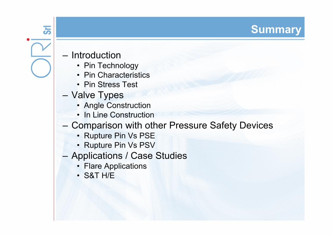
Summary
– Introduction• Pin Technology• Pin Characteristics • Pin Stress Test
– Valve Types• Angle Construction• In Line Construction
– Comparison with other Pressure Safety Devices• Rupture Pin Vs PSE• Rupture Pin Vs PSV
– Applications / Case Studies• Flare Applications• S&T H/E
Summary
– Introduction• Pin Technology• Pin Characteristics • Pin Stress Test
– Valve Types• Angle Construction• In Line Construction
– Comparison with other Pressure Safety Devices• Rupture Pin Vs PSE• Rupture Pin Vs PSV
– Applications / Case Studies• Flare Applications• S&T H/E
IntroductionPin technology
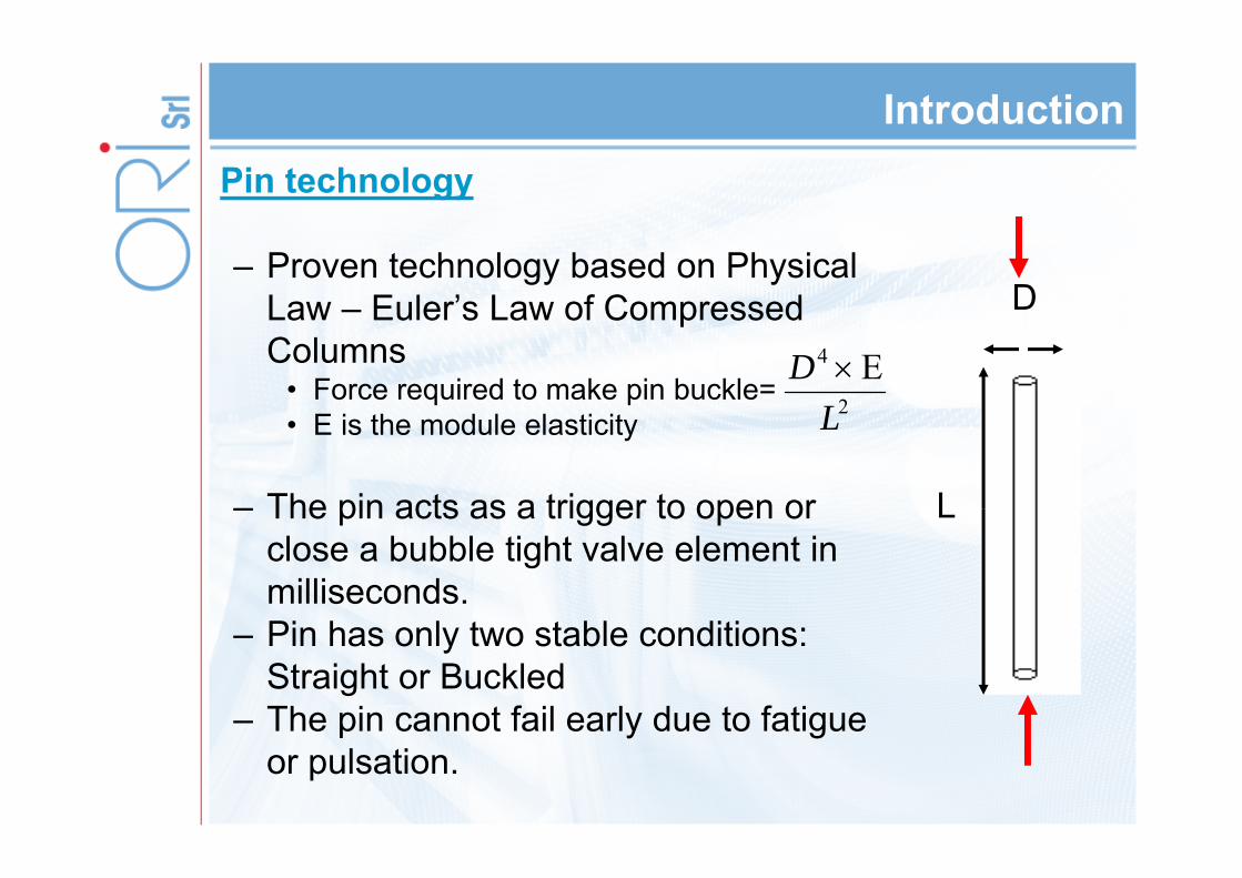
– Proven technology based on Physical Law – Euler’s Law of Compressed Columns
• Force required to make pin buckle= • E is the module elasticity
– The pin acts as a trigger to open or close a bubble tight valve element in milliseconds.
– Pin has only two stable conditions: Straight or Buckled
– The pin cannot fail early due to fatigue or pulsation.
L
D
2
4 E L
D
IntroductionPin Characteristics
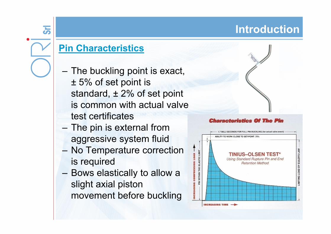
– The buckling point is exact, ± 5% of set point is standard, ± 2% of set point is common with actual valve test certificates
– The pin is external from aggressive system fluid
– No Temperature correction is required
– Bows elastically to allow a slight axial piston movement before buckling
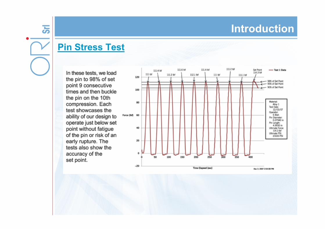
IntroductionPin Stress Test
Summary
– Introduction• Pin Technology• Pin Characteristics • Pin Stress Test
– Valve Types• Angle Construction• In Line Construction
– Comparison with other Pressure Safety Devices• Rupture Pin Vs PSE• Rupture Pin Vs PSV
– Applications / Case Studies• Flare Applications• S&T H/E
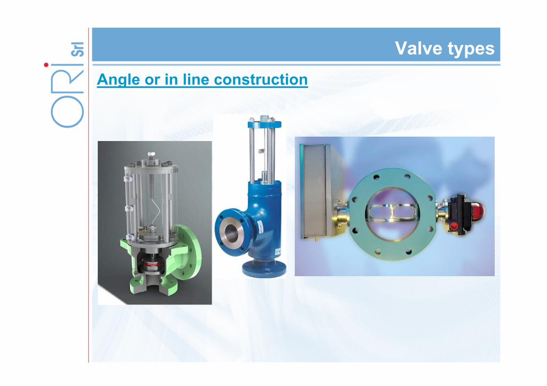
Valve typesAngle or in line construction
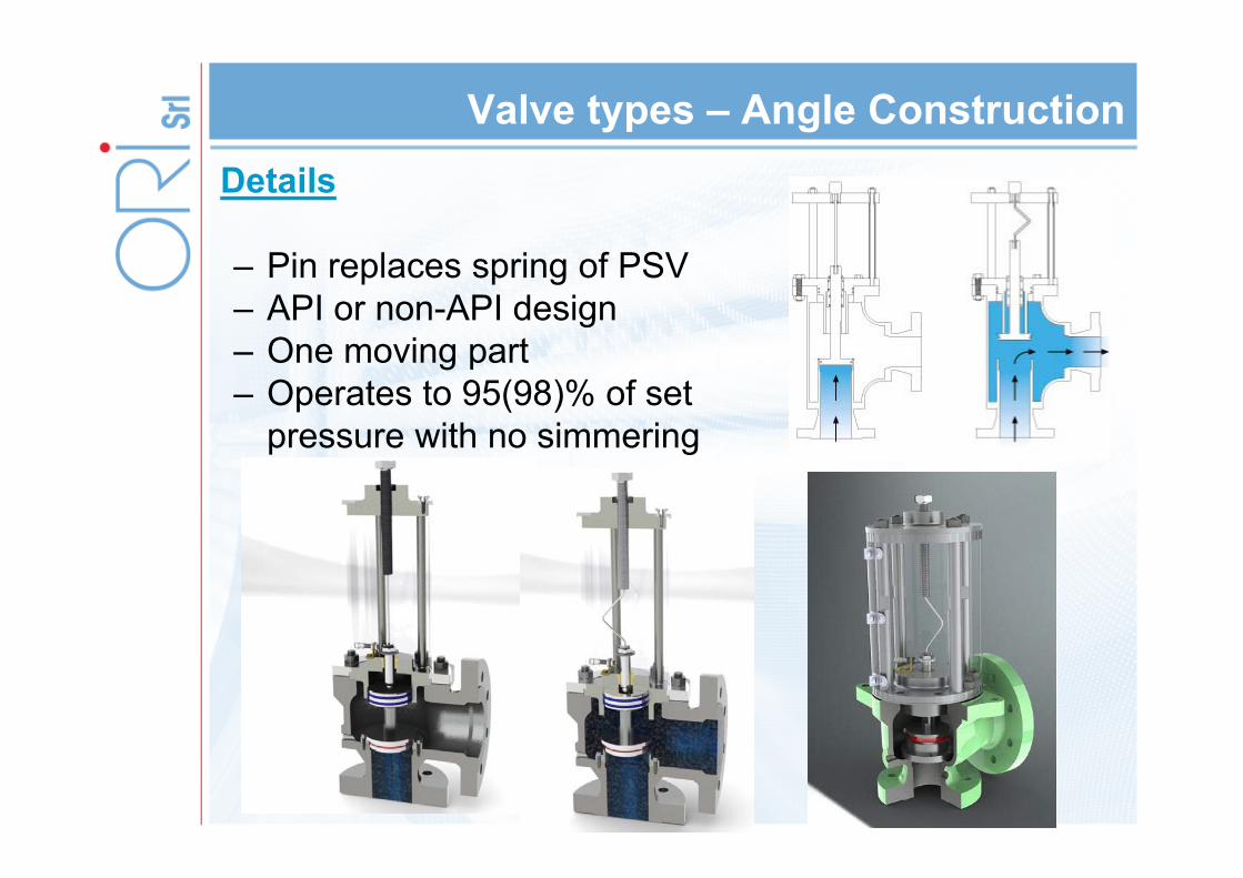
Valve types – Angle ConstructionDetails
– Pin replaces spring of PSV– API or non-API design– One moving part– Operates to 95(98)% of set
pressure with no simmering
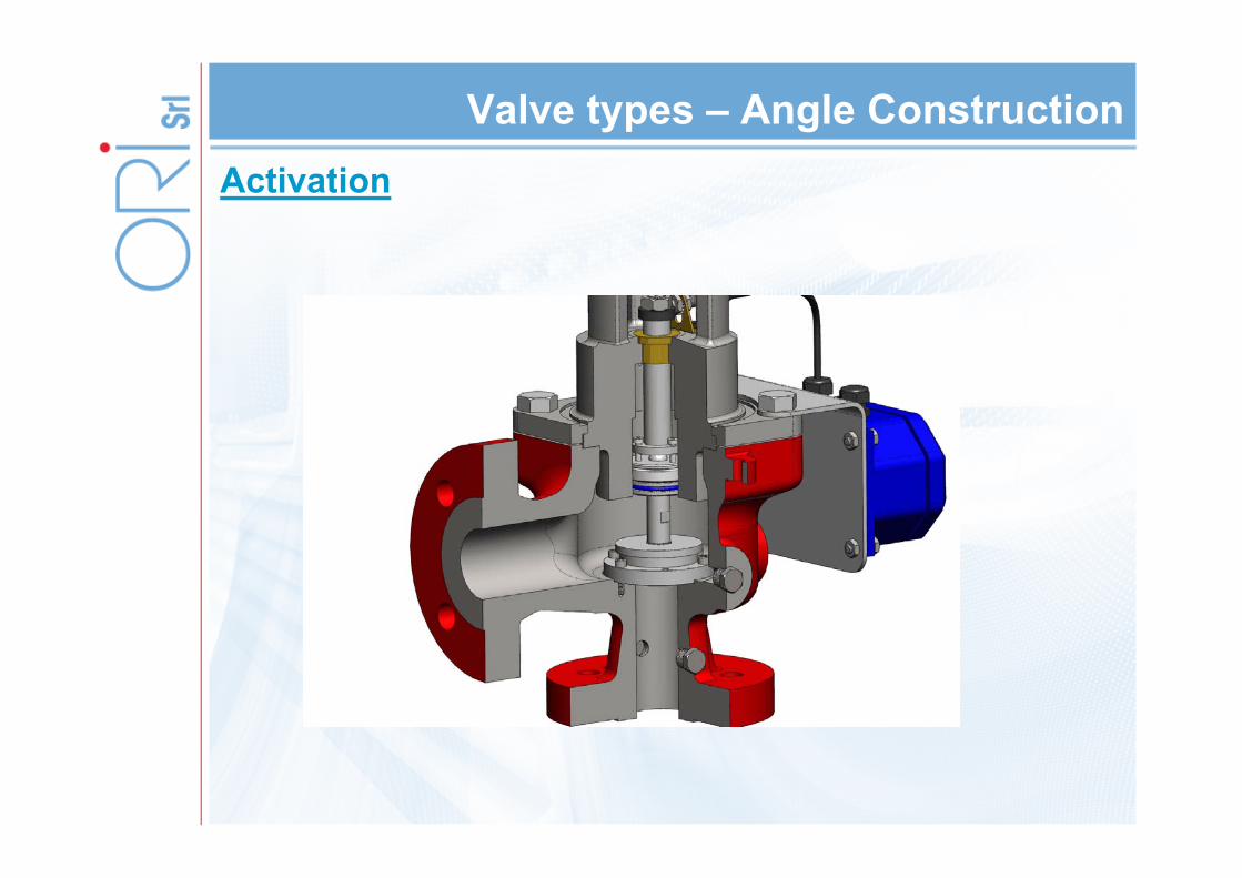
Valve types – Angle ConstructionActivation
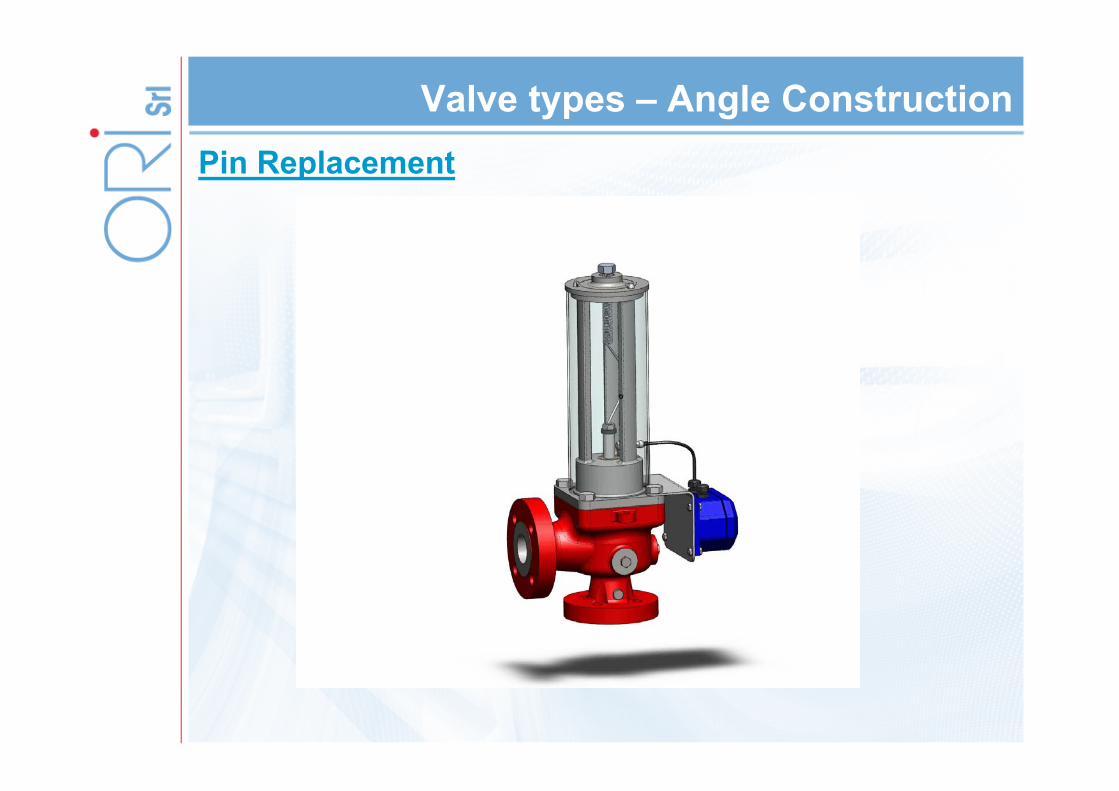
Valve types – Angle ConstructionPin Replacement
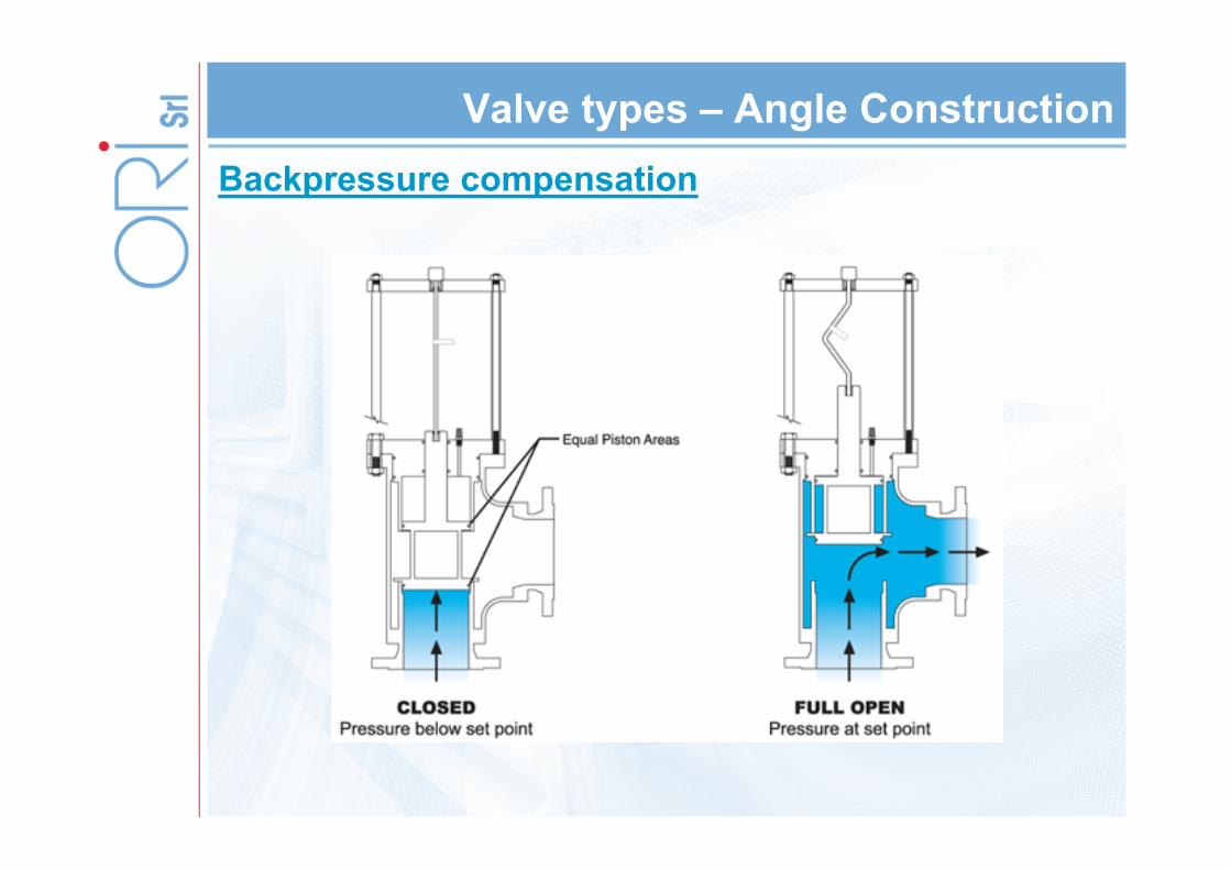
Valve types – Angle ConstructionBackpressure compensation
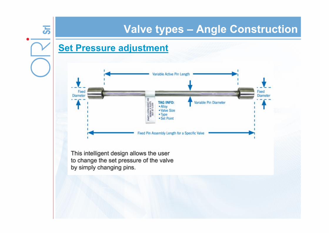
Valve types – Angle ConstructionSet Pressure adjustment

Valve types – Angle ConstructionSet point verification
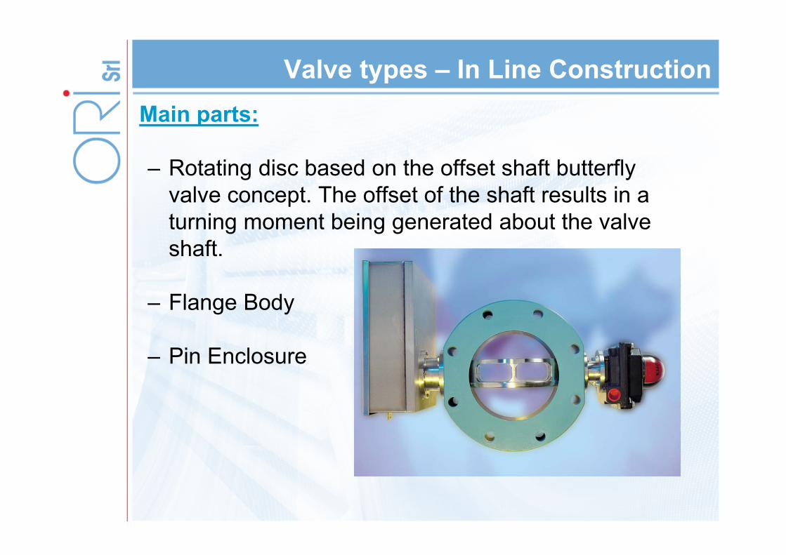
Valve types – In Line ConstructionMain parts:
– Rotating disc based on the offset shaft butterfly valve concept. The offset of the shaft results in a turning moment being generated about the valve shaft.
– Flange Body
– Pin Enclosure
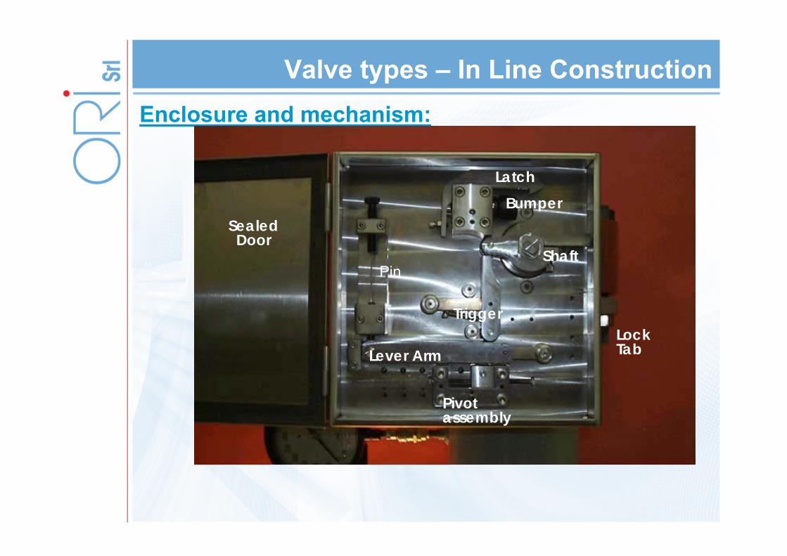
Valve types – In Line ConstructionEnclosure and mechanism:
Lever Arm
Pivot assembly
TriggerLockTab
Shaft
BumperLatch
Pin
Sealed Door
Valve types – In Line ConstructionEnclosure and mechanism:
Lever Arm
Pivot assembly
TriggerLockTab
Shaft
BumperLatch
Pin
Sealed Door
–1.
–2
–3
–4 –5
–6
–7
–8
–9
–10
–10
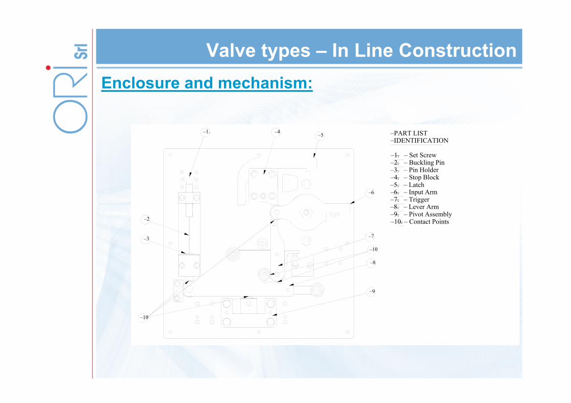
–PART LIST–IDENTIFICATION
–1.– – Set Screw–2.– – Buckling Pin–3.– – Pin Holder–4.– – Stop Block–5.– – Latch–6.– – Input Arm–7.– – Trigger–8.– – Lever Arm–9.– – Pivot Assembly–10.– – Contact Points
Valve types – In Line Construction
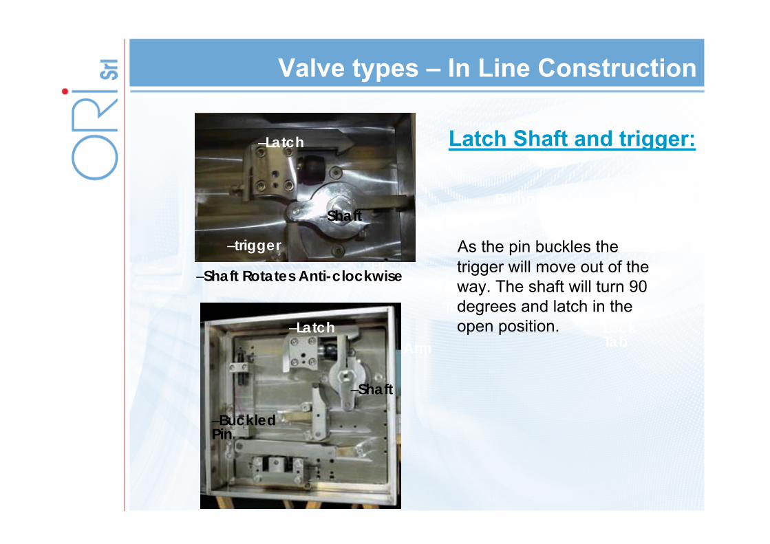
Latch Shaft and trigger:
Lever Arm
TriggerLockTab
Bumper
Pin
Sealed Door
As the pin buckles the trigger will move out of the way. The shaft will turn 90 degrees and latch in the open position.
–Shaft Rotates Anti-clockwise
–Shaft
–Latch
–trigger
–Shaft
–Latch
–Buckled Pin
Valve types – In Line Construction
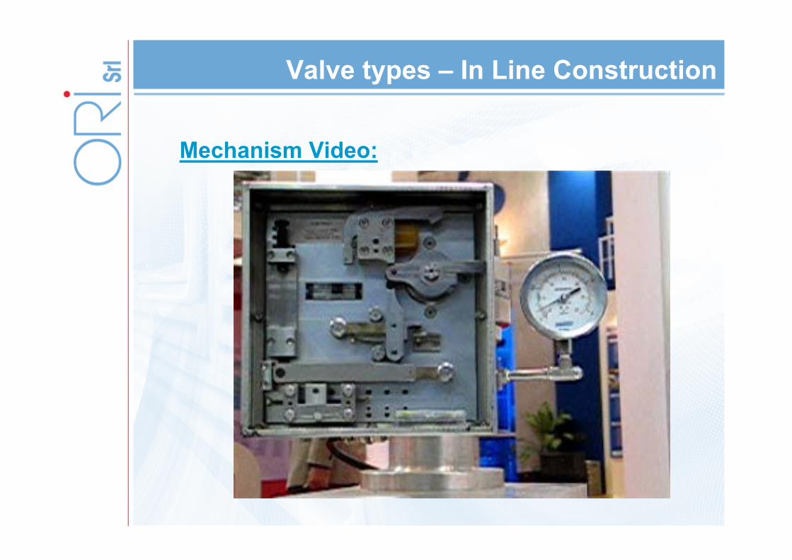
Mechanism Video:

Valve types – In Line Construction
Mechanism Video:

Valve types – In Line Construction
Body:
–Hollow Disc
–ASME Certified Minimum Net Relief Area (MNFA)
dramatically exceeds all other devices
Note sealing surface on inlet side of disc
Valve types – In Line Construction
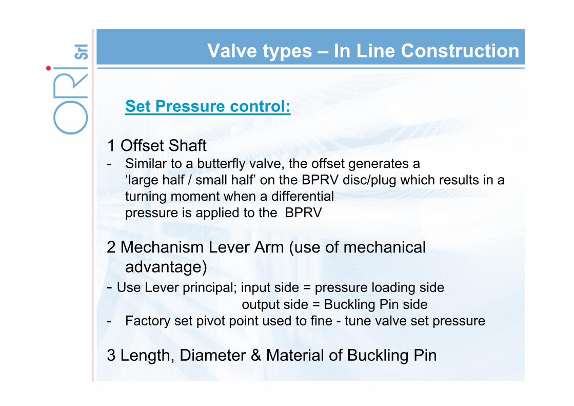
Set Pressure control:
1 Offset Shaft- Similar to a butterfly valve, the offset generates a
‘large half / small half’ on the BPRV disc/plug which results in a turning moment when a differential pressure is applied to the BPRV
2 Mechanism Lever Arm (use of mechanical advantage)
- Use Lever principal; input side = pressure loading sideoutput side = Buckling Pin side
- Factory set pivot point used to fine - tune valve set pressure
3 Length, Diameter & Material of Buckling Pin
Valve types – In Line Construction
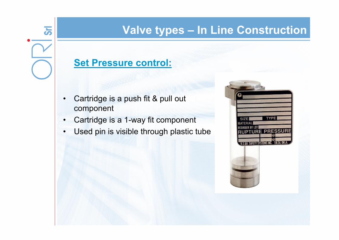
Set Pressure control:
• Cartridge is a push fit & pull out component
• Cartridge is a 1-way fit component• Used pin is visible through plastic tube

Valve types – In Line Construction
60” testing:
Summary
– Introduction• Pin Technology• Pin Characteristics • Pin Stress Test
– Valve Types• Angle Construction• In Line Construction
– Comparison with other Pressure Safety Devices• Rupture Pin Vs PSE• Rupture Pin Vs PSV
– Applications / Case Studies• Flare Applications• S&T H/E
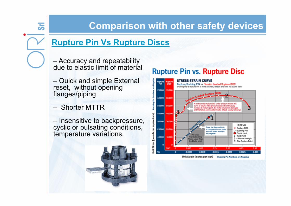
Comparison with other safety devicesRupture Pin Vs Rupture Discs
– Accuracy and repeatability due to elastic limit of material
– Quick and simple External reset, without opening flanges/piping
– Shorter MTTR
– Insensitive to backpressure, cyclic or pulsating conditions, temperature variations.
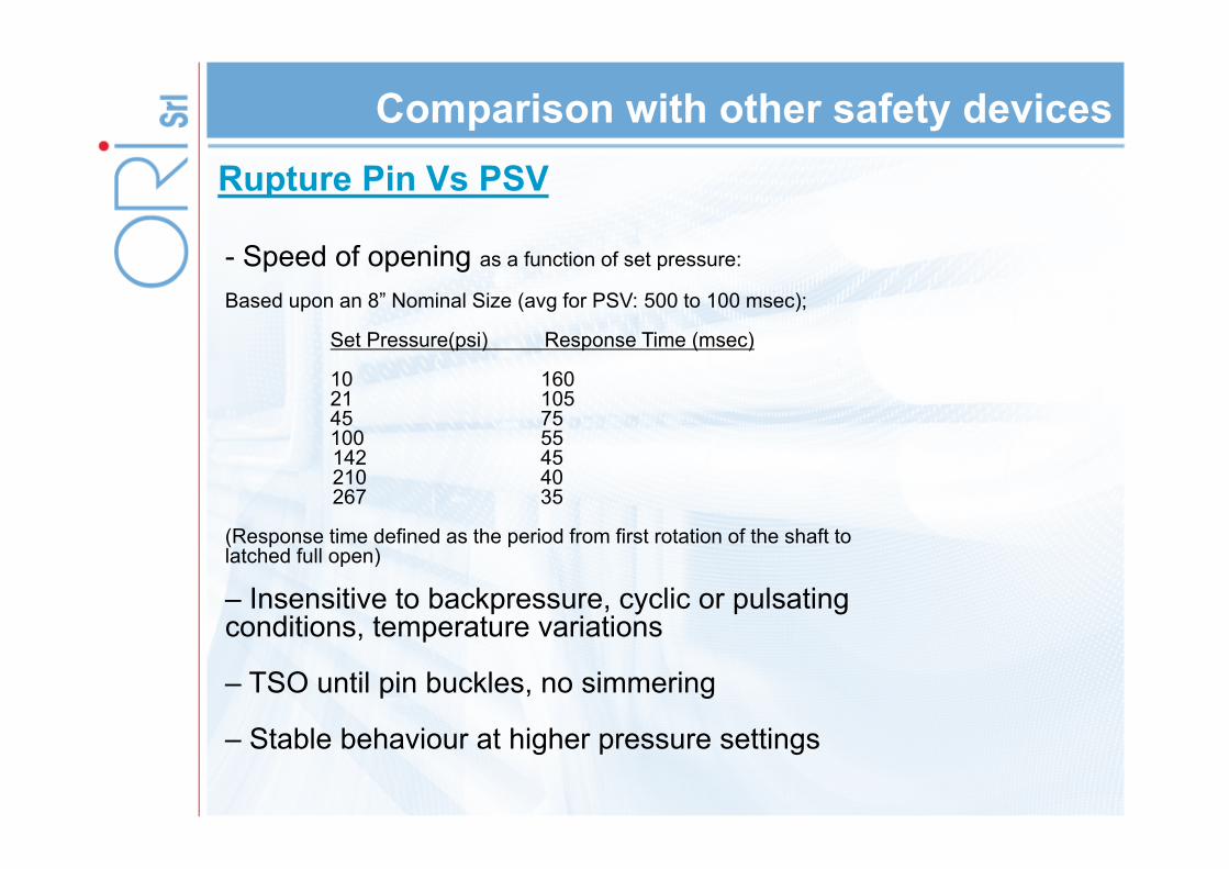
Comparison with other safety devicesRupture Pin Vs PSV
- Speed of opening as a function of set pressure:
Based upon an 8” Nominal Size (avg for PSV: 500 to 100 msec);
Set Pressure(psi) Response Time (msec)
10 16021 10545 75100 55142 45 210 40267 35
(Response time defined as the period from first rotation of the shaft to latched full open)
– Insensitive to backpressure, cyclic or pulsating conditions, temperature variations
– TSO until pin buckles, no simmering
– Stable behaviour at higher pressure settings
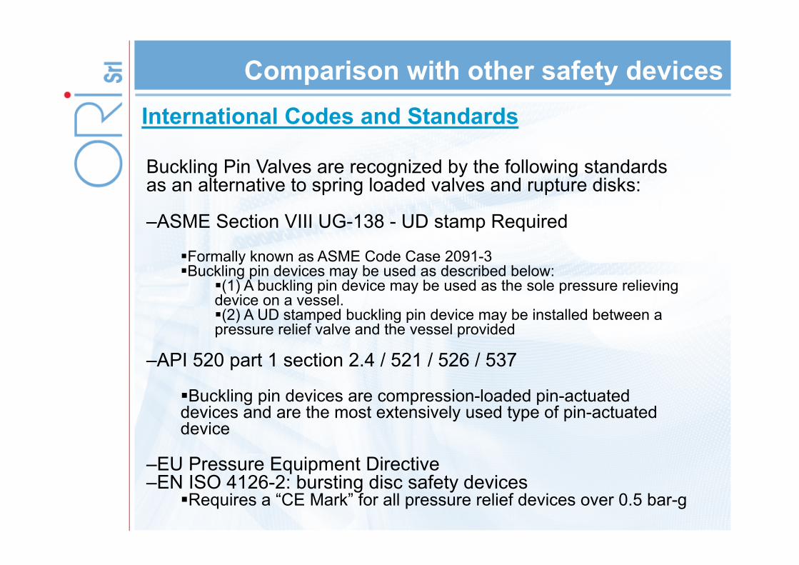
Comparison with other safety devicesInternational Codes and Standards
Buckling Pin Valves are recognized by the following standards as an alternative to spring loaded valves and rupture disks:
–ASME Section VIII UG-138 - UD stamp Required
Formally known as ASME Code Case 2091-3Buckling pin devices may be used as described below:
(1) A buckling pin device may be used as the sole pressure relieving device on a vessel.(2) A UD stamped buckling pin device may be installed between a pressure relief valve and the vessel provided
–API 520 part 1 section 2.4 / 521 / 526 / 537
Buckling pin devices are compression-loaded pin-actuated devices and are the most extensively used type of pin-actuated device
–EU Pressure Equipment Directive–EN ISO 4126-2: bursting disc safety devices
Requires a “CE Mark” for all pressure relief devices over 0.5 bar-g
Summary
– Introduction• Pin Technology• Pin Characteristics • Pin Stress Test
– Valve Types• Angle Construction• In Line Construction
– Comparison with other Pressure Safety Devices• Rupture Pin Vs PSE• Rupture Pin Vs PSV
– Applications / Case Studies• Flare Applications• S&T H/E

Rupture Pin Valves in Flare Systems
Flares:
• A flare system acts for plant safety.
• During normal operation, materials from the refining process are collected and routed to oil recovery tanks for further processing. There, they are converted into products such as gasoline and jet fuel.
• When the operation experiences an interruption, such as an unplanned loss of power, the system is sometimes unable to sendthese excess materials back to the process units for furtherrefining. Instead, the materials are collected and routed to the refinery flare system. There, the liquid and vapors are combinedwith steam and burned off. This system ensures maximum combustion of hydrocarbons while minimizing emissions into the air.
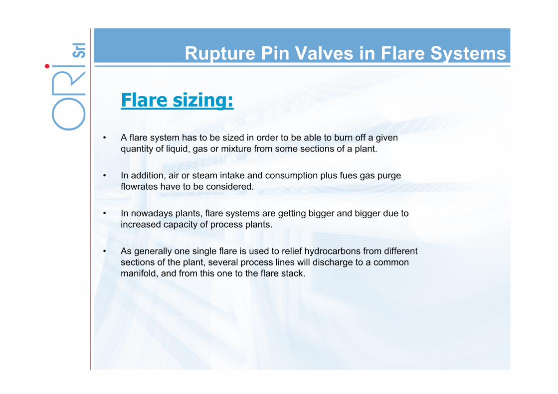
Flare sizing:
• A flare system has to be sized in order to be able to burn off a given quantity of liquid, gas or mixture from some sections of a plant.
• In addition, air or steam intake and consumption plus fues gas purge flowrates have to be considered.
• In nowadays plants, flare systems are getting bigger and bigger due to increased capacity of process plants.
• As generally one single flare is used to relief hydrocarbons from different sections of the plant, several process lines will discharge to a common manifold, and from this one to the flare stack.
Rupture Pin Valves in Flare Systems
Basics of flare system
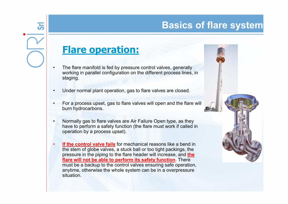
Flare operation:• The flare manifold is fed by pressure control valves, generally
working in parallel configuration on the different process lines, in staging.
• Under normal plant operation, gas to flare valves are closed.
• For a process upset, gas to flare valves will open and the flare will burn hydrocarbons.
• Normally gas to flare valves are Air Failure Open type, as they have to perform a safety function (the flare must work if called in operation by a process upset).
• If the control valve fails for mechanical reasons like a bend in the stem of globe valves, a stuck ball or too tight packings, the pressure in the piping to the flare header will increase, and the flare will not be able to perform its safety function. There must be a backup to the control valves ensuring safe operation, anytime, otherwise the whole system can be in a overpressure situation.

Basics of flare system
Flare protection• The flare stack has to be protected from overpressure
by a mechanical device.(see API537) This is the only option to make sure that the system protection is reliable enough unless you go to a highly expensive HIPPS system designed to open instead of closing, and certified in accordance with IEC 61508/61511 norms in SIL 3 configuration.
• Tipically, the first form of overpressure protection by means of a mechanical system is a safety valve.
• The size limitation to the safety valves (8”x10” according to API 526) has caused some flare manufacturers to look for alternative systems, such as rupture discs.
Basics of flare system
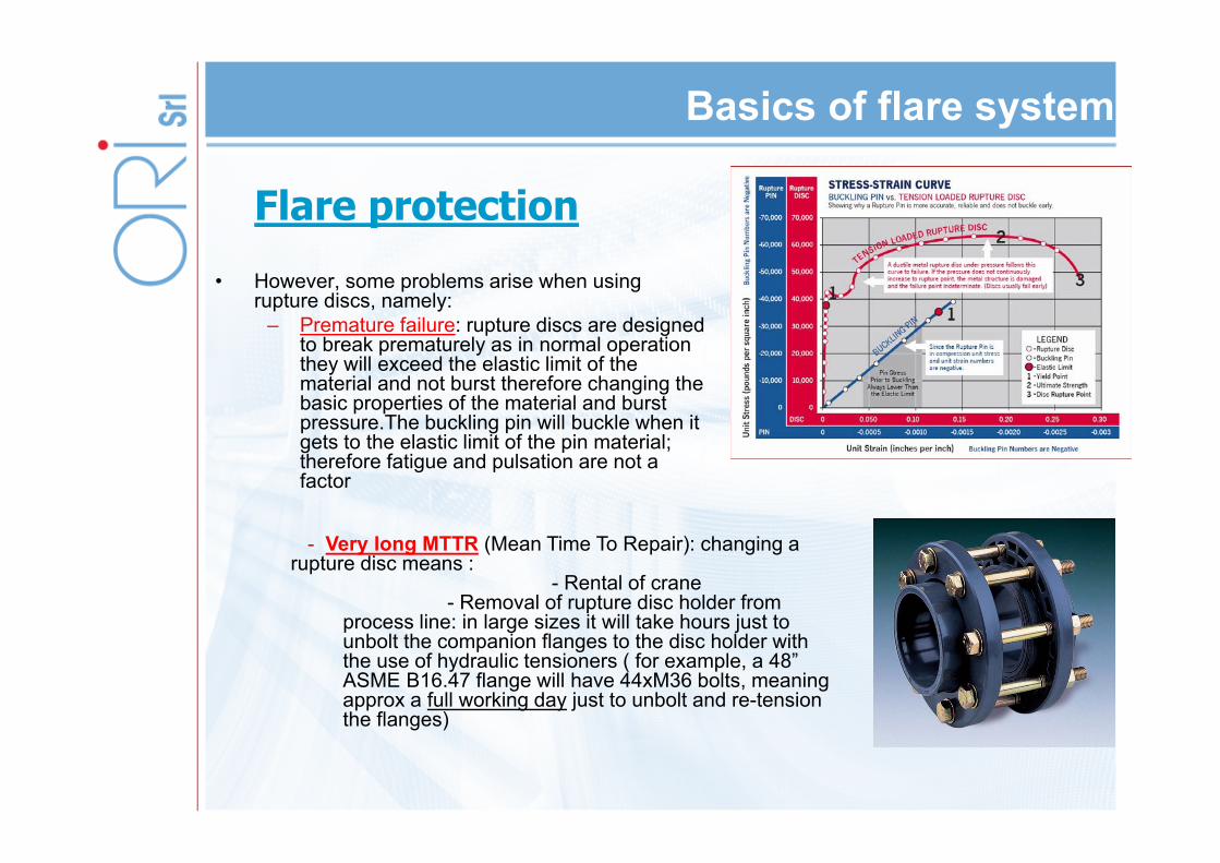
Flare protection• However, some problems arise when using
rupture discs, namely:– Premature failure: rupture discs are designed
to break prematurely as in normal operation they will exceed the elastic limit of the material and not burst therefore changing the basic properties of the material and burst pressure.The buckling pin will buckle when it gets to the elastic limit of the pin material; therefore fatigue and pulsation are not a factor
- Very long MTTR (Mean Time To Repair): changing a rupture disc means :
- Rental of crane- Removal of rupture disc holder from
process line: in large sizes it will take hours just to unbolt the companion flanges to the disc holder with the use of hydraulic tensioners ( for example, a 48” ASME B16.47 flange will have 44xM36 bolts, meaning approx a full working day just to unbolt and re-tension the flanges)

Rupture Pin Valves
The issue is therefore how to protectplant safety by ensuring that the flare
system will be able to operate !
A safe alternative: RUPTURE PIN VALVES
Applications and case studies – Flare Valves
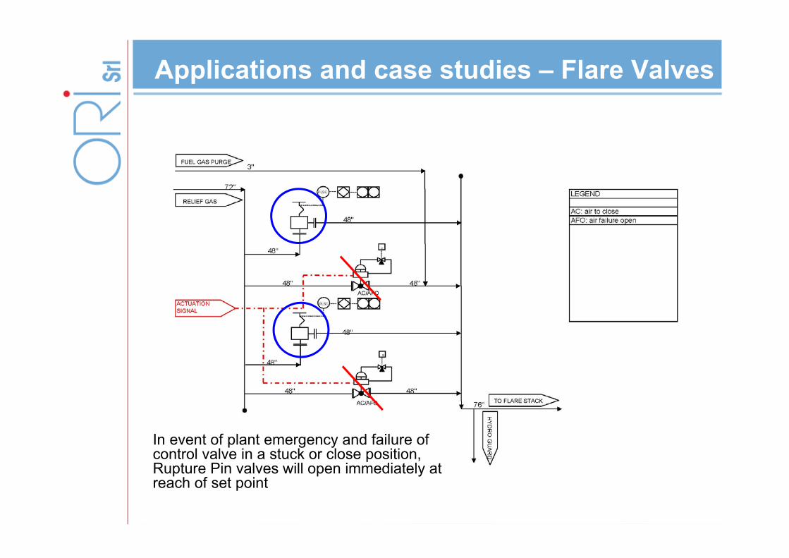
In event of plant emergency and failure of control valve in a stuck or close position, Rupture Pin valves will open immediately at reach of set point

Applications and case studies – Flare Valves

Applications and case studies – Flare Valves
Applications and case studies – S&T H/E
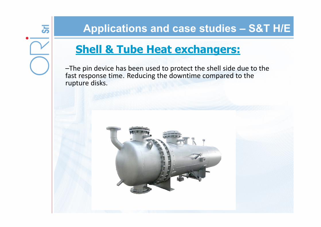
Shell & Tube Heat exchangers:–The pin device has been used to protect the shell side due to the fast response time. Reducing the downtime compared to the rupture disks.
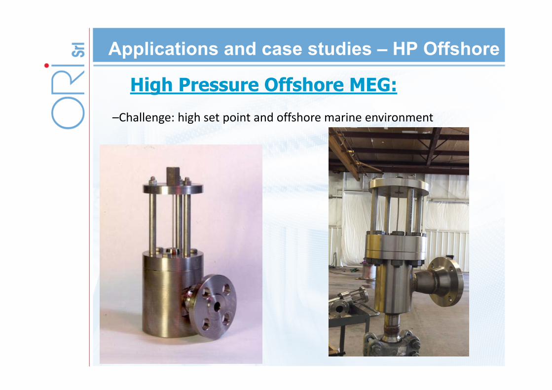
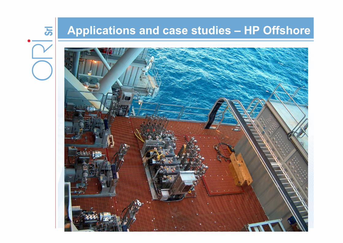
Applications and case studies – HP Offshore
High Pressure Offshore MEG:–Challenge: high set point and offshore marine environment
Applications and case studies – HP Offshore

Applications and case studies – High Viscosity
Pulp & Paper / Rubber plants–Challenge: CIP capability and highly viscous fluid.

Questions?