Gilera Fuoco 500 i.e. (EN)
330
SERVICE STATION MANUAL XXXX Fuoco 500 i.e.
Transcript of Gilera Fuoco 500 i.e. (EN)

7/29/2019 Gilera Fuoco 500 i.e. (EN)
http://slidepdf.com/reader/full/gilera-fuoco-500-ie-en 1/329
SERVICE STATION MANUAL
XXXX
Fuoco 500 i.e.

7/29/2019 Gilera Fuoco 500 i.e. (EN)
http://slidepdf.com/reader/full/gilera-fuoco-500-ie-en 2/329
SERVICE STATION
MANUAL
Fuoco 500 i.e.
The descriptions and images in this publication are given for illustrative purposes only and are not binding.While the basic characteristics as described and illustrated in this booklet remain unchanged, Piaggio &C. S.p.A. reserves the right, at any time and without being required to update this publication beforehand,to make any changes to components, parts or accessories, which it considers necessary to improve the
product or which are required for manufacturing or construction reasons.Not all versions/models shown in this publication are available in all countries. The availability of each
model should be checked at the official PIAGGIO sales network.©Copyright 2011 - Piaggio & C. S.p.A. All rights reserved. Reproduction of this publication in whole or
in part is prohibited.Piaggio & C. S.p.A. Viale Rinaldo Piaggio, 25 - 56025 PONTEDERA (PI), Italy
www.piaggio.com

7/29/2019 Gilera Fuoco 500 i.e. (EN)
http://slidepdf.com/reader/full/gilera-fuoco-500-ie-en 3/329
SERVICE STATION MANUALFuoco 500 i.e.
This service station manual has been drawn up by Piaggio & C. Spa to be used by the workshops of Piaggio-Gilera dealers. It is assumed that the user of this manual for maintaining and repairing Piaggiovehicles has a basic knowledge of mechanical principles and vehicle repair technique procedures. Anysignificant changes to vehicle characteristics or to specific repair operations will be communicated byupdates to this manual. Nevertheless, no mounting work can be satisfactory if the necessary equipmentand tools are unavailable. It is therefore advisable to read the sections of this manual concerning specialtools, along with the special tool catalogue.
N.B. Provides key information to make the procedure easier to understand and carry out.
CAUTION Refers to specific procedures to carry out for preventing damages to the vehicle.
WARNING Refers to specific procedures to carry out to prevent injuries to the repairer.
Personal safety Failure to completely observe these instructions will result in serious risk of personalinjury.
Safeguarding the environment Sections marked with this symbol indicate the correct use of the vehicleto prevent damaging the environment.
Vehicle intactness The incomplete or non-observance of these regulations leads to the risk of seriousdamage to the vehicle and sometimes even the invalidity of the guarantee.

7/29/2019 Gilera Fuoco 500 i.e. (EN)
http://slidepdf.com/reader/full/gilera-fuoco-500-ie-en 4/329

7/29/2019 Gilera Fuoco 500 i.e. (EN)
http://slidepdf.com/reader/full/gilera-fuoco-500-ie-en 5/329
INDEX OF TOPICS
CHARACTERISTICS CHAR
MAINTENANCE MAIN
TROUBLESHOOTING TROUBL
ELECTRICAL SYSTEM ELE SYS
ENGINE FROM VEHICLE ENG VE
ENGINE ENG
INJECTION INJEC
SUSPENSIONS SUSP
BRAKING SYSTEM BRAK SYS
COOLING SYSTEM COOL SYS
CHASSIS CHAS
PRE-DELIVERY PRE DE
TIME TIME

7/29/2019 Gilera Fuoco 500 i.e. (EN)
http://slidepdf.com/reader/full/gilera-fuoco-500-ie-en 6/329
INDEX OF TOPICS
CHARACTERISTICS CHAR
7/29/2019 Gilera Fuoco 500 i.e. (EN)
http://slidepdf.com/reader/full/gilera-fuoco-500-ie-en 7/329
This section describes the general specifications of the vehicle.
Rules
This section describes general safety rules for any maintenance operations performed on the vehicle.
Safety rules
- If work can only be done on the vehicle with the engine running, make sure that the premises are well
ventilated, using special extractors if necessary; never let the engine run in an enclosed area. Exhaust
fumes are toxic.
- The battery electrolyte contains sulphuric acid. Protect your eyes, clothes and skin. Sulphuric acid is
highly corrosive; in the event of contact with your eyes or skin, rinse thoroughly with abundant waterand seek immediate medical attention.
- The battery produces hydrogen, a gas that can be highly explosive. Do not smoke and avoid sparks
or flames near the battery, especially when charging it.
- Fuel is highly flammable and it can be explosive given some conditions. Do not smoke in the working
area, and avoid naked flames or sparks.
- Clean the brake pads in a well-ventilated area, directing the jet of compressed air in such a way that
you do not breathe in the dust produced by the wear of the friction material. Even though the latter
contains no asbestos, inhaling dust is harmful.
Maintenance rules
- Use original PIAGGIO spare parts and lubricants recommended by the Manufacturer. Non-original or
non-conforming spares may damage the vehicle.
- Use only the appropriate tools designed for this vehicle.
- Always use new gaskets, sealing rings and split pins upon refitting.
- After removal, clean the components using non-flammable or low flash-point solvents. Lubricate all
the work surfaces, except tapered couplings, before refitting these parts.- After refitting, make sure that all the components have been installed correctly and work properly.
- For removal, overhaul and refit operations use only tools with metric measures. Metric bolts, nuts and
screws are not interchangeable with coupling members with English measurement. Using unsuitable
coupling members and tools may damage the vehicle.
- When carrying out maintenance operations on the vehicle that involve the electrical system, make
sure the electrical connections have been made properly, particularly the ground and battery connec-
tions.
Fuoco 500 i.e. Characteristics
CHAR - 7

7/29/2019 Gilera Fuoco 500 i.e. (EN)
http://slidepdf.com/reader/full/gilera-fuoco-500-ie-en 8/329
Vehicle identification
Frame prefix (A):
ZAPM61100
Engine prefix (B):
M661M
Dimensions and mass
Characteristics Fuoco 500 i.e.
CHAR - 8

7/29/2019 Gilera Fuoco 500 i.e. (EN)
http://slidepdf.com/reader/full/gilera-fuoco-500-ie-en 9/329
WEIGHTS AND DIMENSIONSSpecification Desc./Quantity
Kerb weight 253 ±5 kgMaximum weight allowed 445 kg
Maximum height 1.210 mmWidth 790 mm
Wheelbase 1,550 mmlength 2.210 mm Track 420 mm
Engine
ENGINESpecification Desc./Quantity
Type Single-cylinder, 4-stroke with double spark plugEngine capacity 493 cm³
Bore x Stroke 94 x 71 mmCompression ratio 10.5: 1Engine idle speed 1,500 ±100 rpm Timing system Four valves, single overhead camshaft, chain-driven.Valve clearance Intake: 0.15 mm
Exhaust: 0.15 mmMax. power 29 kW at 7,500 rpmMAX. torque 44 Nm at 5,200 rpmLubrication Engine lubrication with lobe pump (inside crankcase), chain-
driven, with double filter: mesh and paper.Lubrication pressure 3.5 ÷4 bar
Minimum lubrication pressure (100° C) 0.8 barFuel system Electronic injection with electric fuel pump.
Cooling Forced coolant circulation system.Fuel Unleaded petrol (95 RON)
Transmission
TRANSMISSIONSpecification Desc./Quantity
Transmission Automatic expandable pulley variator with torque server, V-belt, self-ventilating dry automatic centrifugal clutch and trans-
mission housing with forced-circulation air cooling.Final reduction gear Gear reduction unit in oil bath.
Capacities
CAPACITYSpecification Desc./Quantity
Engine oil 1.7 l Transmission oil 250 cm³
Cooling system fluid ~1.8 lFuel tank (reserve) approx. 12 l (approx. 2 l)
Fuoco 500 i.e. Characteristics
CHAR - 9

7/29/2019 Gilera Fuoco 500 i.e. (EN)
http://slidepdf.com/reader/full/gilera-fuoco-500-ie-en 10/329
Electrical system
ELECTRICAL SYSTEMSpecification Desc./Quantity
Starter starterIgnition Electronic, inductive, high efficiency ignition, integrated with the
injection system, with variable advance and separate HV coil.Ignition advance Three-dimensional map managed by control unit
Spark plug NGK CR7EKBAlternative spark plug -
Battery 12V-12AhGenerator alternating current
Frame and suspensions
FRAME AND SUSPENSIONSSpecification Desc./Quantity
Chassis Tubular and sheet steelFront suspension The roll system is composed of an articulated parallelogram
suspension with die-cast aluminium control arms and two sideheadstocks plus shock absorbers with hydraulic locking sys-
tem.Front suspension travel 85 mm
Rear suspension Two double-acting shock absorbers, adjustable to four posi-tions at preloading.
Rear suspension travel 110 mm
Brakes
BRAKESSpecification Desc./Quantity
Front brake Ø 240-mm double disc brake with hydraulic control operatedby the handlebar right-hand lever.
Rear brake Ø 240-mm disc brake with hydraulic control operated by thehandlebar left-hand lever.
Wheels and tyres
WHEELS AND TYRES
Specification Desc./QuantityWheel rim type Light alloy wheel rims.Front rim 12'' x 3.00
Rear wheel rim 14'' x 4.50Front tyre Tubeless, 120/70-12" 51S or 51PRear tyre Tubeless 140/70 - 14" 68S or 68P reinf
Front tyre pressure (with passenger) 1.6 bar (1.8 bar)Rear tyre pressure (with passenger) 2.4 bar (2.6 bar)
Tightening Torques
STEERING
Name Torque in NmSteering lower ring nut (central headstock) 10 to 12Steering upper ring nut (central headstock) 22.5 to 25
Characteristics Fuoco 500 i.e.
CHAR - 10

7/29/2019 Gilera Fuoco 500 i.e. (EN)
http://slidepdf.com/reader/full/gilera-fuoco-500-ie-en 11/329
Name Torque in Nm
Handlebar fixing screw 50 ÷55Fixing screws for the handlebar control unit U-bolts 7 to 10
CHASSIS
Name Torque in NmSwinging arm set screw bushing 5 ÷7
Engine arm bolt - frame arm 32.5 ÷40Swinging arm set screw bushing nut 54 ÷60
Engine-swinging arm bolt 98 ÷118Frame-swinging arm bolt 54 ÷60
Centre stand bolt 31 - 39
FRONT SUSPENSIONName Torque in Nm
Shock absorber lower clamping 19 - 26Shock absorber upper clamp 19 - 29
Front wheel fixing screws 19 ÷24Steering arm bolt nut 20 to 25
Tilt gripper fixing screws 20 to 25Front wheel axle 74 - 88
Arm coupling screws 45 to 50Screws fixing arms to side headstocks 45 to 50
Screws fixing arms to central headstock 45 to 50Screws fixing the half-arm coupling flange 20 to 25
Screws fixing roll lock disc section 20 to 25Side headstock upper ring nut 20 - 24Side headstock lower ring nut 12 ÷15
Screw fixing sliding stem to shock absorber 45 to 50Clamp for sliding stem locking device 6.5 - 10.5
Fixing nuts for constant-velocity universal joints 18 - 20Potentiometer to anti-tilting device clamp 8 to 10Electric motor to anti-tilting device clamp 11 to 13
Clamp fixing pump bolt to anti-tilting device 11 to 13
Pump to anti-tilting device clamp 11 to 13Pressure switch to distribution frame 18 - 20
Sensor to tilt gripper clamp 2.5 - 2.9Pipe terminals to fifth wheel check spring 7 - 11
J oint to anti-tilting device pump 20 to 25Lower fitting for shock absorber sliding locking clamp pipes 20 to 25Upper fitting for shock absorber sliding locking clamp pipes 20 to 25
REAR SUSPENSIONName Torque in Nm
Shock absorber upper clamp 33 to 41Shock absorber lower clamping 33 to 41
Shock absorber-crankcase attachment bracket 20 to 25Rear wheel axle 104 to 126
Silencer arm clamping screws 27 - 30
FRONT BRAKE
Name Torque in Nm
Calliper coupling screw 22 ÷27Oil bleed screw 8 - 12
Disc tightening screw (°) 5 to 6Brake fluid pump-hose fitting 16 - 20Brake fluid pipe-calliper fitting 20 to 25
Screw tightening calliper to support 20 to 25Calliper upper pipe fitting 20 to 25
REAR BRAKE
Name Torque in NmOil bleed screw 12÷16
Rear brake disc screws(°) 5 to 6.5
Fuoco 500 i.e. Characteristics
CHAR - 11

7/29/2019 Gilera Fuoco 500 i.e. (EN)
http://slidepdf.com/reader/full/gilera-fuoco-500-ie-en 12/329
Name Torque in Nm
Rear brake calliper-pipe fitting 20 to 25Rigid / flexible pipe fitting 13 - 18
Rear brake pump-pipe fitting 16 - 20Rear brake calliper fixing screws 20 to 25
pad fastening pin screws 20 ÷25
REAR BRAKEProduct Description Specifications
(°) Loctite 243 Medium strength threadlock Apply LOCTITE 243 medium-strengththreadlock
SILENCER
Name Torque in Nm
Silencer heat guard fixing screw 4 to 5Screw for fixing silencer to supporting arm 20 to 25
Lambda probe tightening on exhaust manifold 40 to 50Exhaust manifold-silencer joint tightening 12÷13
Manifold - silencer diaphragm tightening clamp 16 to 18
LUBRICATIONName Torque in Nm
Oil pump cover screws 0.7 - 0.9Screws fixing oil pump to the crankcase 5 to 6
THERMAL GROUP AND TIMING SYSTEMName Torque in Nm
Spark plug 12 to 14Head fixing stud bolts ***
Head fixing nuts 10 - 12Exhaust / intake head fixing nuts 10 - 12
Head lubrication control jet 5 - 7
Coolant temperature sensor 10 ÷12counterweight mass fixing screw 7 - 8.5
Tensioner sliding block fixing screw 10 - 14Rpm timing sensor fixing screw 3 - 4
injector fixing screw 3 ÷4Revolution timing sensor fixing screw 3 ÷4
Valve lifter mass stop bell fixing screws 30 - 35inlet manifold fixing screws 11 - 13 Tappet cover fixing screws 7 - 9 Throttle body fixing screws 11 ÷13
camshaft retaining bracket fixing screws 4 - 6Head fixing screws 10 - 12
Lambda probe on exhaust manifold 10 - 12Muffler to bracket fixing screw 14 - 16
*** Apply a preliminary torque of 7 Nm in a crossed sequence. - Tighten by 90° in a crossed sequence. - tighten again by 90° in
a criss-crossed sequence.
TRANSMISSION COVERName Torque in Nm
Driven pulley nut 92 - 100Drive pulley nut 160 - 175
Anti-vibration roller screw 16.7 ÷19.6M8 retainers for transmission cover 23 ÷26
M6 retainer 11 ÷13Anti-vibration roller retainer 17 - 19
Clutch ring nut 65 - 75Air deflector unit screws 7 ÷9
Water pump cover screws 3 ÷4External transmission cover screws 7 ÷9
Flywheel cover screws 11 - 13
Characteristics Fuoco 500 i.e.
CHAR - 12

7/29/2019 Gilera Fuoco 500 i.e. (EN)
http://slidepdf.com/reader/full/gilera-fuoco-500-ie-en 13/329
FLYWHEEL COVERName Torque in Nm
Flywheel fixing nut 115 - 125Stator retainers 8 - 10
Blow-by recovery duct fixing screws 3 - 4Screw fixing freewheel to flywheel 13 - 15
Stator cable harness guide bracket screws 3 - 4
CRANKCASE AND CRANKSHAFTName Torque in Nm
Countershaft fixing nut 25 ÷29Engine oil filter 12 - 16
Engine oil drainage plug 24 to 30Engine-crankcase coupling screws 11 to 13
Oil pump screws 5 to 6Gear mounting on crankshaft screws 10 -12
Bulkhead screws for oil pump housing cover 8 - 10
COOLINGName Torque in Nm
Water pump impeller 4 ÷5Water pump cover screws 3 ÷4 Thermostat cover screws 3 to 4
Bleed screw 3
FINAL REDUCTION GEARName Torque in Nm
Rear hub cover screws 24 to 27
ENGINE ASSEMBLY
Name Torque in Nmstarter motor retainers 11 - 13
Overhaul data
Assembly clearances
Fuoco 500 i.e. Characteristics
CHAR - 13

7/29/2019 Gilera Fuoco 500 i.e. (EN)
http://slidepdf.com/reader/full/gilera-fuoco-500-ie-en 14/329
Cylinder - piston assy.
HEIGHT TO MEASURE THE PISTONSpecification Desc./Quantity
A 10 mmB 43 mm
CYLINDER - PISTONSpecification Desc./Quantity
Cylinder diameter C 94 +0.018-0.01mmPiston diameter P 93.968 - ±0.014 mm
COUPLING CATEGORIESName Initials Cylinder Piston Play on fitting
Cylinder- Piston A 93.990÷93.997 93.954÷93.961 0.029÷0.043Cylinder- Piston B 93.997÷93.004 93.961÷93.968 0.029÷0.043Cylinder- Piston C 94.004÷94.011 93.968÷93.975 0.029÷0.043Cylinder- Piston D 94.011÷94.018 93.975÷93.982 0.029÷0.043
N.B.
THE PISTON MUST BE INSTALLED WITH THE ARROW FACING TOWARDS THE EXHAUST SIDE,THE PISTON RINGS MUST BE INSTALLED WITH THE WORD «TOP» OR THE STAMPED MARKFACING UPWARDS.
Characteristics Fuoco 500 i.e.
CHAR - 14

7/29/2019 Gilera Fuoco 500 i.e. (EN)
http://slidepdf.com/reader/full/gilera-fuoco-500-ie-en 15/329
Piston rings
*Fit rings «2» and «3» with the word «TOP» facing upwards.
** Position the port of the rings as shown here.
*** Value «A» of seal ring inside the cylinder.
Check the size of the sealing ring opening:
Compression ring: 0.15 - 0.35 mm. Max. value 0.5 mm
Oil scraper ring: 0.25 - 0.50 mm. Max. value 0.65 mm
Oil scraper ring: 0.25 - 0.50 mm. Max. value 0.65 mm
Rings/housing coupling clearances:
Carefully clean the sealing ring housings.
Place a feeler gauge between the ring and the
housing as shown in the drawing and check the
coupling clearances.
Top ring Standard coupling clearance:
0.01-0.06 mm
Maximum clearances allowed after use: 0.10
mm
Intermediate ring Standard coupling clear-
ance:0.02-0.07 mm
Maximum clearances allowed after use: 0.10
mm
Fuoco 500 i.e. Characteristics
CHAR - 15

7/29/2019 Gilera Fuoco 500 i.e. (EN)
http://slidepdf.com/reader/full/gilera-fuoco-500-ie-en 16/329
Oil scraper ring Standard coupling clearance:
0.01-0.06 mm
Maximum clearances allowed after use: 0.10
mm
Replace the piston if clearances exceed the max-
imum limits specified in the table.
Crankcase - crankshaft - connecting rod
AXIAL CLEARANCE BETWEEN CRANKSHAFT AND CONNECTING RODName Description Dimensions Initials Quantity
Transmission-sideshoulder
1 ±0.025 A D =0.20 ÷0.50
Half-shaft, transmissionside
20.9 - 0.05 B D =0.20 ÷0.50
Connecting rod 22 0.10 - 0.15 C D =0.20 ÷0.50Flywheel-side shoulder 1.8 ±0.025 F D =0.20 ÷0.50Flywheel side half-shaft 19.6 +0.05 E D =0.20 ÷0.50
Complete crankshaft 65.5 +0.1 -0.05 G D =0.20 ÷0.50
Characteristics Fuoco 500 i.e.
CHAR - 16

7/29/2019 Gilera Fuoco 500 i.e. (EN)
http://slidepdf.com/reader/full/gilera-fuoco-500-ie-en 17/329
Diameter of crankshaft bearings.
Measure the bearings on both axes x-y.
CRANKSHAFTSpecification Desc./Quantity
Cat. 1 Standard diameter: 40.010 ÷40.016Cat. 2 Standard diameter: 40.016 ÷40.022
Crankshaft alignment
Specific tooling
020335Y Magnetic mounting for dial gauge
MAX. ADMISSIBLE DISPLACEMENTSpecification Desc./Quantity
A = 0.15 mmB = 0.010 mmC = 0.010 mmD = 0.10 mm
Fuoco 500 i.e. Characteristics
CHAR - 17

7/29/2019 Gilera Fuoco 500 i.e. (EN)
http://slidepdf.com/reader/full/gilera-fuoco-500-ie-en 18/329
Characteristic
Crankshaft-crankcase axial clearance (H)
0.1 ÷0.405 mm (when cold)
Compression ratio
10.5: 1
Slot packing system
Shimming system to control compression ratio
DISTANCE «A» IS A PROTRUSION OR RECESS VALUE OFTHE PISTON CROWN WITH RESPECT TO THE CYLINDERPLANE.DISTANCE «A» HELPS DETERMINE THE THICKNESS OFGASKET «B» THAT HAS TO BE FITTED TO THE CYLINDERHEAD IN ORDER TO RESTORE COMPRESSION RATIO.BASE GASKET «B» MUST BE THICKER THE MORE THEPLANE FORMED BY THE PISTON CROWN PROTRUDESFROM THE PLANE FORMED BY THE CYLINDER HEAD. ONTHE OTHER HAND, THE MORE THE PISTON CROWN ISRECESSED INTO THE CYLINDER TOP PLANE, THESMALLER THE GASKET THICKNESS.
Characteristic
Compression ratio
10.5: 1
Characteristics Fuoco 500 i.e.
CHAR - 18

7/29/2019 Gilera Fuoco 500 i.e. (EN)
http://slidepdf.com/reader/full/gilera-fuoco-500-ie-en 19/329
BASE GASKET THICKNESSName Measure A Thickness
«A» MEASURE TAKEN - 0.185 - - 0.10 0.4 ±0.05«A» MEASURE TAKEN - 0.10 - +0.10 0.6 ±0.05
«A» MEASURE TAKEN +0.10 - +0.185 0.8 ±0.05N.B.
VALUES INDICATED WITH «-» REFER TO PISTON CROWN RECESSES WITH RESPECT TO THECYLINDER PLANE.
N.B.
DISTANCE «A» MUST BE MEASURED WITHOUT ANY GASKET FITTED AT «B»
Products
RECOMMENDED PRODUCTS TABLE
Product Description Specifications
AGIP ROTRA 80W-90 Rear hub oil SAE 80W/90 Oil that exceeds the re-quirements of API GL3 specifications
AGIP CITY HI TEC 4T Oil to lubricate flexible transmissions(throttle control)
Oil for 4-stroke engines
AGIP FILTER OIL Oil for air filter sponge Mineral oil with specific additives for in-creased adhesiveness
AGIP GP 330 Grease for brake lever, gas White calcium complex soap-basedspray grease with NLGI 2; ISO-L-XBCIB2
AGIP CITY HI TEC 4T Engine oil SAE 5W-40, API SL, ACEA A3, J ASO MASynthetic oil
AGIP BRAKE 4 Brake fluid FMVSS DOT 4 Synthetic fluidAGIP PERMANENT SPEZIAL coolant Monoethylene glycol-based antifreeze
fluid, CUNA NC 956-16
Fuoco 500 i.e. Characteristics
CHAR - 19

7/29/2019 Gilera Fuoco 500 i.e. (EN)
http://slidepdf.com/reader/full/gilera-fuoco-500-ie-en 20/329
INDEX OF TOPICS
MAINTENANCE MAIN

7/29/2019 Gilera Fuoco 500 i.e. (EN)
http://slidepdf.com/reader/full/gilera-fuoco-500-ie-en 21/329
Follow these steps to reset the service icons:
1. With the key set to OFF, hold down the
"SET" button and turn the key to ON : the
"BELT" and "SERVICE" icons start flashing.
2. Push the "CLOCK" button for less than 1
second and the icons are displayed sequen-
tially. The icon selected remains ON and the
other is no longer displayed.
3. Press the "CLOCK" button again for more
than 3 seconds to reset the relative mainte-
nance step and the icon is no longer dis-
played.
Maintenance chart
EVERY 2 YEARS
60'
Action
Coolant - changeBrake fluid - change
AFTER 1,000 KM60'
Action
Safety fasteners - check Throttle lever - adjustmentEngine oil filter - changeElectrical system and battery - checkCoolant level - checkBrake fluid level - checkEngine oil - changeBrake pads - check for condition and wear Tyre pressure and wear - checkVehicle test and brake test - Road testHub oil - change
Steering - Check
AFTER 5,000 KM; 25,000 KM; 35,000 KM; 55,000 KM; 65,000 KM
10'
Action
Engine oil - level check/ top-upBrake pads - check for condition and wearCentre stand - lubrication
AFTER 10,000 KM; 50,000 KM; 70,000 KM
Action
Safety fasteners - checkDrive belt - replacement
Throttle lever - adjustmentAir filter - cleanEngine oil filter - change
Fuoco 500 i.e. Maintenance
MAIN - 21

7/29/2019 Gilera Fuoco 500 i.e. (EN)
http://slidepdf.com/reader/full/gilera-fuoco-500-ie-en 22/329
Action
Electrical system and battery - checkCoolant level - checkBrake fluid level - checkEngine oil - changeBrake pads - check for condition and wear
Sliding shoes / CVT rollers - replace Tyre pressure and wear - checkVehicle test and brake test - Road testHub oil - checkSuspension - checkSteering - CheckCentre stand - lubricationSpark plugs - replacement Tilt locking gripper control cable - adjustmentParking control unit software upgrading (if available)
AFTER 15,000 KM; 45,000 KM; 75,000 KM
10'
ActionEngine oil - level check/ top-upBrake pads - check for condition and wearCentre stand - lubrication
AFTER 20,000 KM; 40,000 KM; 60,000 KM AND 80,000 KMAction
Spark plugs - replacementDrive belt - replacement Throttle lever - adjustmentAir filter - checkEngine oil filter - changeValve clearance - checkElectrical system and battery - check
Coolant level - checkEngine oil - changeBrake pads - check for condition and wearSliding shoes / CVT rollers - replace Tyre pressure and wear - checkVehicle test and brake test - Road testHub oil - changeSuspension - checkSteering - CheckCentre stand - lubricationBrake fluid level - check Tilt locking gripper control cable - adjustmentParking control unit software upgrading (if available)
30,000 KMAction
Safety fasteners - checkDrive Belt - replacement Throttle lever - adjustmentAir filter - cleanEngine oil filter - changeElectrical system and battery - checkCoolant level - checkBrake fluid level - checkEngine oil - changeHub oil - checkBrake pads - check for condition and wearSliding shoes / CVT rollers - replace Tyre pressure and wear - check
Vehicle test and brake test - Road testSuspension - checkSteering - Check
Maintenance Fuoco 500 i.e.
MAIN - 22

7/29/2019 Gilera Fuoco 500 i.e. (EN)
http://slidepdf.com/reader/full/gilera-fuoco-500-ie-en 23/329
Action
Centre stand - lubricationSpark plugs - replacement Tilt locking gripper control cable - adjustmentParking control unit software upgrading (if available)
Checking the spark advance
The ignition advance is determined electronically
on the basis of parameters known by the control
unit. For this reason it is not possible to interpret
the reference values based on the engine rpm.
The ignition advance value is detectable at any
time using the diagnostic tester. It is possible to
check whether the ignition advance determined by
the injection system matches the value actually
activated on the engine, by means of the strobo-
scopic light.
Proceed as follows:
- Remove the spark plugs.
- Remove the transmission crankcase.
- Rotate the driving pulley fan until the reference
marks between the flywheel and flywheel covermeet as shown in the photograph.
- Bring the reference mark onto the transmission
side between the fan and the transmission cover
as shown in the photograph.
Fuoco 500 i.e. Maintenance
MAIN - 23

7/29/2019 Gilera Fuoco 500 i.e. (EN)
http://slidepdf.com/reader/full/gilera-fuoco-500-ie-en 24/329
- Refit the spark plugs.
- Refit the plastic cap on the flywheel cover.
- Adjust the spark gap to the contact position (no
reference mark visible) and install it on engine be-
tween the spark plug and spark plug cap
- Connect the induction clamp to the spark gap
cable respecting the proper polarity (the arrow on
the clamp must be pointing at the spark plug).
- Connect the diagnostic tester.
- Start the engine.
- Select the «parameters» function in this menu.
- Select the stroboscopic light control in the tradi-tional four-stroke engine position (1 spark, 2 revs).
- Check that the real values of rpm and ignition
advance match those measured using the diag-
nostic tester.
If the values do not correspond, check:
- distribution timing
- revolution timing sensor
- injection control unit
Specific tooling
020680Y Diagnosis Tool
020330Y Stroboscopic light to check timing
020621Y HV cable extraction adaptor
Spark plug
Remove the port on the left-hand side panel of the
vehicle by undoing the fixing screw and using a
small screwdriver in the rear recess shown in the
figure, then do the following:
- Disconnect the HV wire caps «A» of the spark
plugs;
- Unscrew the spark plugs using the wrench sup-
plied;
Maintenance Fuoco 500 i.e.
MAIN - 24

7/29/2019 Gilera Fuoco 500 i.e. (EN)
http://slidepdf.com/reader/full/gilera-fuoco-500-ie-en 25/329
- Upon refitting, place the spark plugs at the re-
quired angle and tighten by hand until it is finger
tight;
- Use the wrench only for final tightening of the
spark plug;
- Place cap «A» fully over the spark plugs
- Refit the port making sure the rear hook is inser-
ted.
WARNING
THE SPARK PLUG MUST BE REMOVED WHEN THE EN-GINE IS COLD. REPLACE THE SPARK PLUG AS INDICA-
TED IN THE SCHEDULED MAINTENANCE TABLE. THEUSE OF ELECTRONIC CENTRAL UNITS AND OF NON-COMPLIANT ELECTRONIC IGNITIONS OR SPARK PLUGSOTHER THAN THOSE PRESCRIBED MAY SERIOUSLYDAMAGE THE ENGINE.
N.B.
USE OF SPARK PLUGS OTHER THAN THE INDICATEDTYPE OR UNSHIELDED SPARK PLUG CAPS CAN LEADTO FAULTS IN THE VEHICLE 'S ELECTRICAL SYSTEM.
Characteristic
Spark plug
NGK CR7EKB
Electric characteristic
Electrode gap
0.7 to 0.8 mm
Hub oil
Check
-Place the vehicle on the centre stand on flat
ground;
- Remove the oil dipstick «A», dry it with a clean
cloth and put it back into its hole tightening it
completely;
Fuoco 500 i.e. Maintenance
MAIN - 25

7/29/2019 Gilera Fuoco 500 i.e. (EN)
http://slidepdf.com/reader/full/gilera-fuoco-500-ie-en 26/329
Remove the dipstick and check that the oil level is
slightly over the second notch starting from the
lower end; if the level is below the MAX mark, it
needs to be filled up with the right amount of hub
oil.
-Screw up the oil dipstick again and make sure it
is locked properly into place.
Replacement
-Remove the oil filler cap «A».
- Unscrew the oil drainage cap «B» and drain out
all the oil.
- Screw in the drainage cap again and fill the hub
with the prescribed oil.
Recommended products
AGIP ROTRA 80W-90 Rear hub oil
SAE 80W/90 Oil that exceeds the requirements of
API GL3 specifications
Characteristic
Rear hub oil
Capacity approximately 250 cc
Air filter
Proceed as follows:
Unscrew the nine fixing screws «A» and remove
the air filter cover.
- Wash the sponge with water and mild soap.
Maintenance Fuoco 500 i.e.
MAIN - 26

7/29/2019 Gilera Fuoco 500 i.e. (EN)
http://slidepdf.com/reader/full/gilera-fuoco-500-ie-en 27/329
- Dry it with a clean cloth and short blasts of compressed air.
- Soak it in a mixture of 50% petrol and 50% specified oil.
- Gently squeeze the filtering element with your hands but do not wring it; allow it to drip dry and then
refit.CAUTION
IF THE VEHICLE IS USED ON DUSTY ROADS IT IS NECESSARY TO CARRY OUT MAINTENANCECHECKS OF THE AIR FILTER MORE OFTEN TO AVOID DAMAGING THE ENGINE.
Recommended products
AGIP FILTER OIL Oil for air filter sponge
Mineral oil with specific additives for increased adhesiveness
Engine oil
In four stroke engines, the engine oil is used to lubricate the distribution elements, the bench bearings
and the thermal group. An insufficient quantity of oil can cause serious damage to the engine.
In all four stroke engines, the deterioration of the oil characteristics, or a certain consumption should
be considered normal, especially if during the run-in period. Consumption levels in particular can be
influenced by the conditions of use (e.g.: oil consumption increases when driving at "full throttle".
Replacement
Change oil and replace filter as indicated in the
scheduled maintenance table. Empty the engine
by draining the oil through drainage plug «B».
To facilitate oil drainage, loosen the cap/dipstick
«A».
Fuoco 500 i.e. Maintenance
MAIN - 27

7/29/2019 Gilera Fuoco 500 i.e. (EN)
http://slidepdf.com/reader/full/gilera-fuoco-500-ie-en 28/329
Once all the oil has drained through the drainage
hole, unscrew and remove the oil cartridge filter
«C ».
Make sure the pre-filter and drainage plug O-rings
are in good conditions.
Lubricate them and refit the mesh filter and the oil
drainage plug, screwing them up to the prescribedtorque.
Refit the new cartridge filter being careful to lubri-
cate the O-ring before fitting it.
Change the engine oil.
Since a certain quantity of oil still remains in the
circuit, engine oil must be added through plug
«A». Then start the vehicle, leave it running for a
few minutes and switch it off: after five minutes
check the level and if necessary top up without
exceeding the MAX level. The cartridge filter must
be replaced every time the oil is changed. Use new
oil of the recommended type for topping up and
changing purposes.
N.B.
THE ENGINE MUST BE HOT WHEN THE OIL IS CHANGED.
Recommended products
AGIP CITY HI TEC 4T Engine oil
SAE 5W-40 Synthetic oil that exceed the require-
ments of API SL, ACEA A3, J ASO MA specifica-
tions
Locking torques (N*m)
Engine oil filter 12 - 16 Engine oil drainage plug24 to 30
Maintenance Fuoco 500 i.e.
MAIN - 28

7/29/2019 Gilera Fuoco 500 i.e. (EN)
http://slidepdf.com/reader/full/gilera-fuoco-500-ie-en 29/329
Check
This operation must be carried out with the engine
cold and following the procedure below:
- Place the vehicle on its centre stand and on flat
ground.
- Unscrew the cap/dipstick «A», dry it with a clean
cloth and reinsert it, screwing it all the way
down.
- Remove the cap/dipstick again and check that
the level is between the min and max reference
marks; top-up, if required.
If the check is carried out after the vehicle has
been used, and therefore with a hot engine, the
level line will be lower; in order to carry out a cor-
rect check, wait at least 10 minutes after the en-
gine has been stopped so as to get the correct
level.
Oil top up
The oil should be topped up after having checked
the level and in any case by adding oil without
ever exceeding the MAX. level.
Restoring the level from theMIN to theMAX marks
requires approx. 400 m³ of oil.
Engine oil filter
The cartridge filter must be replaced every time the oil is changed. Use new oil of the recommended
type for topping up and changing purposes.
Make sure the pre-filter and drainage plug O-rings are in good conditions. Lubricate them and refit the
mesh filter and the oil drainage plug, screwing them up to the prescribed torque. Refit the new cartridge
filter being careful to lubricate the O-ring before fitting it. Change the engine oil.
Recommended products
AGIP CITY HI TEC 4T Engine oil
SAE 5W-40 Synthetic oil that exceed the requirements of API SL, ACEA A3, J ASO MA specifications
Fuoco 500 i.e. Maintenance
MAIN - 29

7/29/2019 Gilera Fuoco 500 i.e. (EN)
http://slidepdf.com/reader/full/gilera-fuoco-500-ie-en 30/329
Oil pressure warning light
The vehicle is equipped with a telltale light on the
dashboard that lights up when the key is turned to
the «ON» position. However, this light should
switch off once the engine has been started.
If the light turns on during braking, at idling
speed or while turning a corner, it is necessary
to check the oil level and the lubrication sys-
tem.
Checking the ignition timing
- Remove the plastic cap on the flywheel cover
-Turn the flywheel until the reference mark «T» on
the rotor matches the reference mark on the fly-
wheel cover as shown in the figure (TDC). Make
sure that the 4V reference point on the camshaft
control pulley is aligned with the reference point on
the head as shown in the second figure. If the ref-
erence is opposite the indicator on the head, turn
the crankshaft once more.
For the use of this reference mark, remove the
spark plug and turn the engine in the direction that
is the reverse of the normal direction using a cal-
liper spanner applied to the camshaft command
pulley casing.
Cooling system
Adding engine coolant.
Check coolant level when the engine is cold as in-
dicated in the scheduled maintenance table, fol-
lowing the steps below:
Place the vehicle on its centre stand and on flat
ground.
Maintenance Fuoco 500 i.e.
MAIN - 30
7/29/2019 Gilera Fuoco 500 i.e. (EN)
http://slidepdf.com/reader/full/gilera-fuoco-500-ie-en 31/329
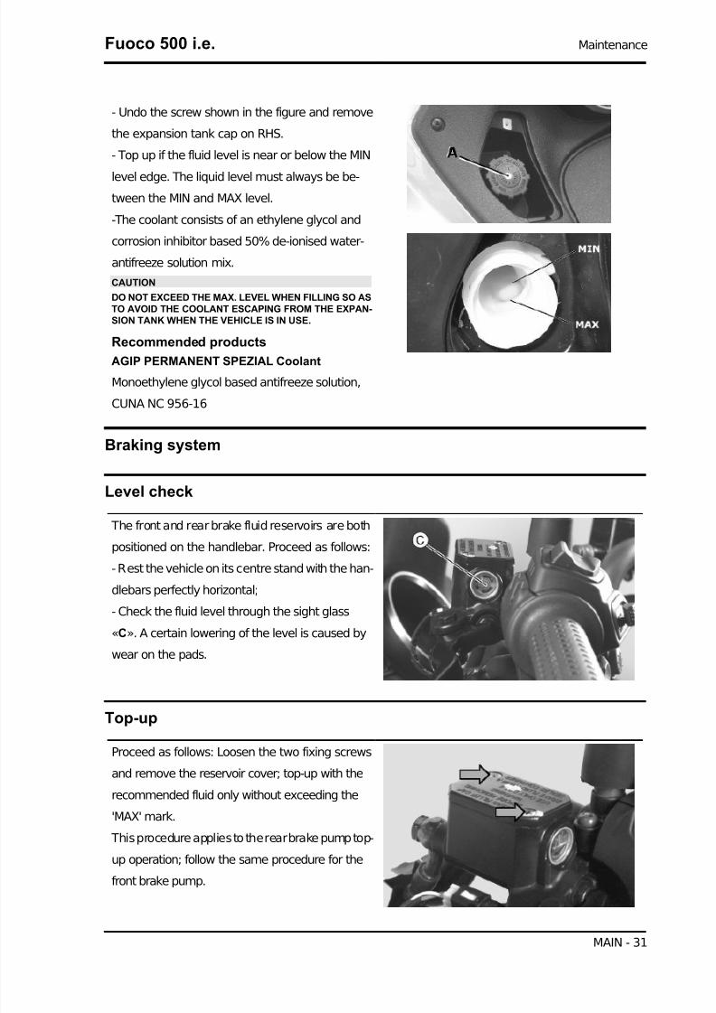
- Undo the screw shown in the figure and remove
the expansion tank cap on RHS.
- Top up if the fluid level is near or below the MIN
level edge. The liquid level must always be be-
tween the MIN and MAX level.
-The coolant consists of an ethylene glycol and
corrosion inhibitor based 50% de-ionised water-
antifreeze solution mix.
CAUTION
DO NOT EXCEED THE MAX. LEVEL WHEN FILLING SO ASTO AVOID THE COOLANT ESCAPING FROM THE EXPAN-SION TANK WHEN THE VEHICLE IS IN USE.
Recommended products
AGIP PERMANENT SPEZIAL Coolant
Monoethylene glycol based antifreeze solution,
CUNA NC 956-16
Braking system
Level check
The front and rear brake fluid reservoirs are both
positioned on the handlebar. Proceed as follows:
- Rest the vehicle on its centre stand with the han-
dlebars perfectly horizontal;
- Check the fluid level through the sight glass
«C». A certain lowering of the level is caused by
wear on the pads.
Top-up
Proceed as follows: Loosen the two fixing screws
and remove the reservoir cover; top-up with the
recommended fluid only without exceeding the
'MAX' mark.
This procedure applies to the rear brake pump top-
up operation; follow the same procedure for the
front brake pump.
Fuoco 500 i.e. Maintenance
MAIN - 31

7/29/2019 Gilera Fuoco 500 i.e. (EN)
http://slidepdf.com/reader/full/gilera-fuoco-500-ie-en 32/329
Under standard climatic conditions, replace cool-
ant as indicated in the scheduled maintenance
table.
WARNING
ONLY USE DOT 4 CLASS BRAKE FLUIDS. BRAKING CIR-CUIT FLUIDS ARE HIGHLY CORROSIVE. MAKE SURETHAT IT DOES NOT COME INTO CONTACT WITH THEPAINTWORK.
CAUTION
AVOID CONTACT OF THE BRAKE FLUID WITH YOUREYES, SKIN, AND CLOTHING. IN CASE OF ACCIDENTALCONTACT, WASH WITH WATER.
Recommended products
AGIP BRAKE 4 Brake fluid
FMVSS DOT4 Synthetic fluid
Headlight adjustment
Proceed as follows:
- Position the unloaded vehicle, in running order
and with the tyres inflated to the prescribed pres-
sure, onto a flat surface 10 m away from a half-lit
white screen; make sure the vehicle axis is per-
pendicular to the screen.
- Remove the headlight assembly central cover.
- Turn on the headlight and check that the border-
line of the projected light beam should be lower
than 9/10 of the distance from the ground to the
centre of the vehicle's headlight, and higher than
7/10.
- Otherwise, adjust the headlight.
N.B.
THE ABOVE PROCEDURE COMPLIES WITH THE EURO-PEAN STANDARDS REGARDING MAXIMUM AND MINI-MUM HEIGHT OF LIGHT BEAMS. REFER TO THE STATU-TORY REGULATIONS IN FORCE IN EVERY COUNTRYWHERE THE VEHICLE IS USED.
Maintenance Fuoco 500 i.e.
MAIN - 32

7/29/2019 Gilera Fuoco 500 i.e. (EN)
http://slidepdf.com/reader/full/gilera-fuoco-500-ie-en 33/329
To access the headlight adjusting screws:
- Unscrew the four screws «A» (two on each side)
and remove the front cowl.
- Unscrew the four screws «B» and remove the
side cover.
Each bulb has two light beam adjusting screws,
one for horizontal adjustment «C» and one for the
vertical adjustment «D». Adjust one headlamp at
a time. In order to do that, remove the connector
from the other bulbs so that you can adjust one
headlamp at a time.
N.B.
THE HEADLAMPS CAN ONLY BE LIT WHEN THE ENGINEIS ON. ADJUST THE LIGHT BEAM IN A WELL VENTILATEDPLACE.
Fuoco 500 i.e. Maintenance
MAIN - 33

7/29/2019 Gilera Fuoco 500 i.e. (EN)
http://slidepdf.com/reader/full/gilera-fuoco-500-ie-en 34/329
INDEX OF TOPICS
TROUBLESHOOTING TROUBL

7/29/2019 Gilera Fuoco 500 i.e. (EN)
http://slidepdf.com/reader/full/gilera-fuoco-500-ie-en 35/329
This section makes it possible to find what solutions to apply when troubleshooting.
For each failure, a list of the possible causes and pertaining operations is given.
Engine
Excessive oil consumption/Exhaust smoke
EXCESSIVE CONSUMPTIONPossible Cause Operation
Wrong valve adjustment Adjust the valve clearance properlyOverheated valves Remove the head and the valves, grind or replace the valves
Misshapen/worn valve seats Replace the head unitWorn cylinder, Worn or broken piston rings Replace the piston cylinder assembly or piston rings
Worn or broken piston rings or piston rings that have not been
fitted properly
Replace the piston cylinder unit or just the piston rings
Oil leaks from the couplings or from the gaskets Check and replace the gaskets or restore the coupling sealWorn valve oil seal Replace the valve oil sealWorn valve guides Check and replace the head unit if required
Insufficient lubrication pressure
POOR LUBRICATION PRESSUREPossible Cause Operation
By-Pass remains open Check the By-Pass and replace if required. Carefully clean theBy-Pass area.
Oil pump with excessive clearance Perform the dimensional checks on the oil pump components
Oil filter too dirty Replace the cartridge filterOil level too low Restore the level adding the recommended oil type
Transmission and brakes
Clutch grabbing or performing inadequately
IRREGULAR CLUTCH PERFORMANCE OR SLIPPAGEPossible Cause Operation
Faulty clutch Check that there is no grease on the masses. Check that the
clutch mass faying surface with the bell is mainly in the centrewith equivalent characteristics on the three masses. Check thatthe clutch casing is not scored or worn in an anomalous way
Insufficient braking
INEFFICIENT BRAKING SYSTEMPossible Cause Operation
Inefficient braking system Check the pad wear (1.5 min). Check that the brake discs arenot worn, scored or warped. Check the correct level of fluid inthe pumps and change brake fluid if necessary. Check there isno air in the circuits; if necessary, bleed the air. Check that the
front brake calliper moves in axis with the disc.Fluid leakage in hydraulic braking system Failing elastic fittings, plunger or brake pump seals, replace
Fuoco 500 i.e. Troubleshooting
TROUBL - 35

7/29/2019 Gilera Fuoco 500 i.e. (EN)
http://slidepdf.com/reader/full/gilera-fuoco-500-ie-en 36/329
Possible Cause Operation
Brake disc slack or distorted Check the brake disc screws are locked; measure the axial shiftof the disc with a dial gauge and with wheel mounted on the
vehicle.
Brakes overheating
BRAKE OVERHEATPossible Cause Operation
Defective plunger sliding Check calliper and replace any damaged part.Brake disc slack or distorted Check the brake disc screws are locked; use a dial gauge and
a wheel mounted on the vehicle to measure the axial shift of the disc.
Clogged compensation holes on the pump Clean carefully and blast with compressed airSwollen or stuck rubber gaskets Replace gaskets.
Steering and suspensions
Heavy steering
STEERING HARDENINGPossible Cause Operation
Steering hardening Check the tightening of the top and bottom ring nuts. If irregu-larities continue in turning the steering even after making theabove adjustments, check the seats in which the ball bearingsrotate: replace them if they are recessed or if the balls are flat-
tened.
Excessive steering play
EXCESSIVE STEERING CLEARANCEPossible Cause Operation
Torque not conforming Check the tightening of the top and bottom ring nuts. If irregu-larities continue in turning the steering even after making theabove adjustments, check the seats in which the ball bearingsrotate: replace them if they are recessed or if the balls are flat-
tened.
Noisy suspension
NOISY SUSPENSIONPossible Cause Operation
Faults in the suspension system If the front suspension is noisy, check: the efficiency of the frontshock absorber; the condition of the ball bearings and relevantlock-nuts, the limit switch rubber buffers; and the movementbushings. In conclusion, check the tightening torque of the
wheel hub, the brake calliper, the shock absorber disc in theattachment to the hub and the steering tube.
Troubleshooting Fuoco 500 i.e.
TROUBL - 36

7/29/2019 Gilera Fuoco 500 i.e. (EN)
http://slidepdf.com/reader/full/gilera-fuoco-500-ie-en 37/329
Suspension oil leakage
OIL LEAKAGE FROM SUSPENSION
Possible Cause Operation
Faulty or broken seals Replace the shock absorber Check the condition of wear of thesteering covers and the adjustments.
Fuoco 500 i.e. Troubleshooting
TROUBL - 37

7/29/2019 Gilera Fuoco 500 i.e. (EN)
http://slidepdf.com/reader/full/gilera-fuoco-500-ie-en 38/329
INDEX OF TOPICS
ELECTRICAL SYSTEM ELE SYS

7/29/2019 Gilera Fuoco 500 i.e. (EN)
http://slidepdf.com/reader/full/gilera-fuoco-500-ie-en 39/329
KEY
1. Parking electronic control unit
2. Right speed sensor
3. Left speed sensor
4. Potentiometer
5. Rider presence sensor
6. Magneto flywheel
7. Locking/unlocking switch
8. LV socket
9. Voltage regulator
10. Main fuses
11. Key switch contacts
12. Auxiliary fuses
13. Key switch contacts
14. Fuse
15. Battery
16. Starter motor
17. Start-up remote control switch
18. Saddle opening actuator
19. Start-up enabling remote control
Fuoco 500 i.e. Electrical system
ELE SYS - 39

7/29/2019 Gilera Fuoco 500 i.e. (EN)
http://slidepdf.com/reader/full/gilera-fuoco-500-ie-en 40/329
20. Stop button on rear brake
21. Stop button on front brake
22. Starter button
23. Saddle opening receiver
24. Wiring for antitheft device
25. Helmet compartment light switch
26. Turn indicator switch
27. Turn signal command device
28. Hazard button
29. Light switch
30. Headlight remote control
31. Helmet compartment light bulb32. License plate light bulb
33. Rear left turn indicator
34. Rear light
A. Tail light bulbs
B. Stop light bulbs
35. Rear right turn indicator
36. Front left turn indicator
37. Headlight
A. Left low-beam light bulb
B. Left high-beam light bulb
C. Tail light bulb
D. Right low-beam light bulb
E. Right high-beam light bulb
38. Front right turn indicator
39. Oil pressure sensor
40. Engine stop switch
41. Fuel level transmitter
42. MODE button
43. Instrument panel
44. Hand brake
45. External temperature sensor
46. Horn
47. Horn button
48. Horn remote control
49. Pressure sensor50. Injection load remote control
Electrical system Fuoco 500 i.e.
ELE SYS - 40

7/29/2019 Gilera Fuoco 500 i.e. (EN)
http://slidepdf.com/reader/full/gilera-fuoco-500-ie-en 41/329
51. Injector
52. Fuel pump
53. Revolution sensor
54. HV coil
55. Injection ECU
56. Immobilizer aerial
57. Brake calliper sensor
58. Diagnosis connector
59. Coolant temperature sensor
60. Lambda probe
61. MIU control unit power device
62. Electric fan remote control63. Electric fan
64. Geared motor
Key
Ar: Orange Az: Sky Blue Bi: White Bl: Blue Gi: Yellow Gr: Grey
Ma:Brown Ne: Black Ro: Pink Rs: Red Ve: Green Vi: Purple
Components arrangement
Fuoco 500 i.e. Electrical system
ELE SYS - 41

7/29/2019 Gilera Fuoco 500 i.e. (EN)
http://slidepdf.com/reader/full/gilera-fuoco-500-ie-en 42/329
1. Relays for lights/ horn/ injection load/ electric
fan: remove the front shield to reach these relays.
2 - Auxiliary fuses: remove the footrest flap to
reach these fuses.
Electrical system Fuoco 500 i.e.
ELE SYS - 42
7/29/2019 Gilera Fuoco 500 i.e. (EN)
http://slidepdf.com/reader/full/gilera-fuoco-500-ie-en 43/329
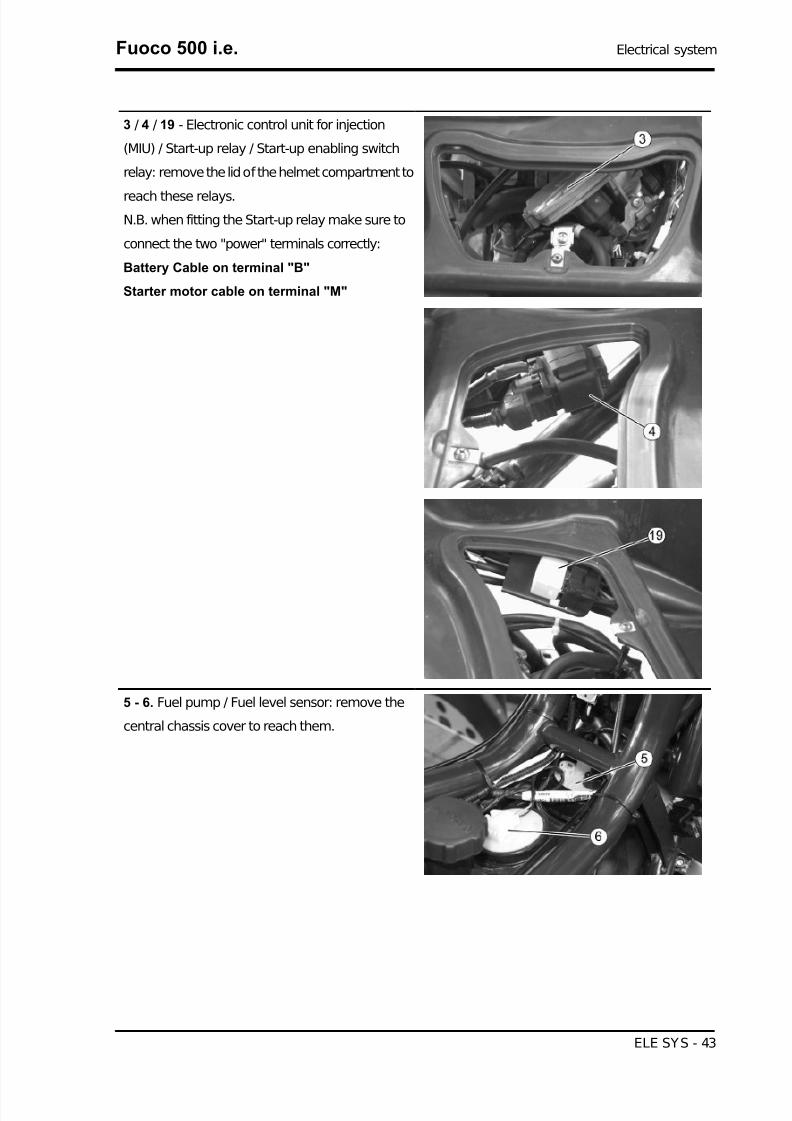
3 / 4 / 19 - Electronic control unit for injection
(MIU) / Start-up relay / Start-up enabling switch
relay: remove the lid of the helmet compartment to
reach these relays.
N.B. when fitting the Start-up relay make sure to
connect the two "power" terminals correctly:
Battery Cable on terminal "B"
Starter motor cable on terminal "M"
5 - 6. Fuel pump / Fuel level sensor: remove the
central chassis cover to reach them.
Fuoco 500 i.e. Electrical system
ELE SYS - 43

7/29/2019 Gilera Fuoco 500 i.e. (EN)
http://slidepdf.com/reader/full/gilera-fuoco-500-ie-en 44/329
10.Coil: remove the helmet compartment to reach
it.
7 - Voltage regulator: remove the right side fairing
to reach them.
8 - Immobilizer aerial: remove the shield back plate
to reach it.
9 / 18 - Saddle opening receiver/ Turn indicator
control device: to reach it, remove the left fairing.
Electrical system Fuoco 500 i.e.
ELE SYS - 44

7/29/2019 Gilera Fuoco 500 i.e. (EN)
http://slidepdf.com/reader/full/gilera-fuoco-500-ie-en 45/329
11 / 12 - Diagnostics socket/ main fuses: these
components are found in the battery compartment.
13 - Lambda probe: The lambda probe is mounted
on the exhaust manifold.
14 - Engine oil pressure sensor: remove the ex-
haust end to reach it.
21 - Geared motor assembly: remove the legshield
to reach it.
Fuoco 500 i.e. Electrical system
ELE SYS - 45

7/29/2019 Gilera Fuoco 500 i.e. (EN)
http://slidepdf.com/reader/full/gilera-fuoco-500-ie-en 46/329
16 - Rider presence sensor: open the saddle and
remove the cover to reach the rider presence sen-
sor.
17 - Coolant temperature sensor: remove the lid of
the helmet compartment and disconnect the con-
nector to reach it.
20 - Horn: remove the shield back plate lower side
to reach it.
21 - 22. Plug socket/helmet compartment light:
open the saddle to reach it.
Conceptual diagrams
Electrical system Fuoco 500 i.e.
ELE SYS - 46

7/29/2019 Gilera Fuoco 500 i.e. (EN)
http://slidepdf.com/reader/full/gilera-fuoco-500-ie-en 47/329
Ignition
KEY
10. Main fuses
11. Key switch contacts
12. Auxiliary fuses
15. Battery
50. Injection load remote control
54. HV coil
55. Injection ECU
56. Immobilizer aerial61. MIU control unit power device
Fuoco 500 i.e. Electrical system
ELE SYS - 47

7/29/2019 Gilera Fuoco 500 i.e. (EN)
http://slidepdf.com/reader/full/gilera-fuoco-500-ie-en 48/329
Battery recharge and starting
KEY
6. Magneto flywheel
9. Voltage regulator
10. Main fuses
11. Key switch contacts
12. Auxiliary fuses
14. Fuse
15. Battery
16. Starter motor17. Start-up remote control switch
19. Start-up enabling remote control
20. Stop button on rear brake
21. Stop button on front brake
22. Starter button
34. Rear light
B. Stop light bulbs
40. Engine stop switch
55. Injection ECU
Electrical system Fuoco 500 i.e.
ELE SYS - 48

7/29/2019 Gilera Fuoco 500 i.e. (EN)
http://slidepdf.com/reader/full/gilera-fuoco-500-ie-en 49/329
61. MIU control unit power device
Level indicators and enable signals section
KEY
1. Parking electronic control unit
2.Right speed sensor
3.Left speed sensor
4. Potentiometer
5. Rider presence sensor
10. Main fuses
11. Key switch contacts
12. Auxiliary fuses
15. Battery
39. Oil pressure sensor
41. Fuel level transmitter
42. MODE button
43. Instrument panel
45. External temperature sensor
50. Injection load remote control
51. Injector
Fuoco 500 i.e. Electrical system
ELE SYS - 49

7/29/2019 Gilera Fuoco 500 i.e. (EN)
http://slidepdf.com/reader/full/gilera-fuoco-500-ie-en 50/329
53. Rpm sensor
55. Injection ECU
56. Immobilizer aerial
57. Brake calliper sensor
59. Coolant temperature sensor
60. Lambda probe
61. MIU control unit power device
Devices and accessories
KEY
1. Parking electronic control unit
7. Locking/unlocking switch
8. LV socket
10. Main fuses
11. Key switch contacts
12. Auxiliary fuses
13. Key switch contacts
15. Battery
18. Saddle opening actuator
23. Saddle opening receiver
Electrical system Fuoco 500 i.e.
ELE SYS - 50

7/29/2019 Gilera Fuoco 500 i.e. (EN)
http://slidepdf.com/reader/full/gilera-fuoco-500-ie-en 51/329
24. Wiring for antitheft device
25. Helmet compartment light switch
31. Helmet compartment light bulb
42. MODE button
43. Instrument panel
46. Horn
47. Horn button
48. Horn remote control
49. Pressure sensor
50. Injection load remote control
52. Fuel pump
55. Injection ECU58. Diagnosis connector
61. MIU control unit power device
62. Electric fan remote control
63. Electric fan
64. Geared motor
Lights and turn indicators
KEY
Fuoco 500 i.e. Electrical system
ELE SYS - 51

7/29/2019 Gilera Fuoco 500 i.e. (EN)
http://slidepdf.com/reader/full/gilera-fuoco-500-ie-en 52/329
1. Parking electronic control unit
10. Main fuses
11. Key switch contacts
12. Auxiliary fuses
13. Key switch contacts
15. Battery
26. Turn indicator switch
27. Turn signal command device
28. Hazard button
29. Light switch
30. Headlight remote control
32. License plate light bulb33. Rear left turn indicator
34. Rear light
A. Tail light bulbs
35. Rear right turn indicator
36. Front left turn indicator
37. Headlight
A. Left low-beam light bulb
B. Left high-beam light bulb
C. Tail light bulb
D. Right low-beam light bulb
E. Right high-beam light bulb
38. Front right turn indicator
43. Instrument panel
Checks and inspections
This section is dedicated to the checks on the electrical system components.
Electrical system Fuoco 500 i.e.
ELE SYS - 52
7/29/2019 Gilera Fuoco 500 i.e. (EN)
http://slidepdf.com/reader/full/gilera-fuoco-500-ie-en 53/329
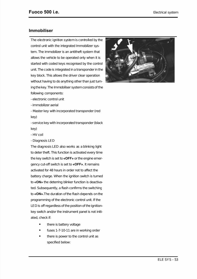
Immobiliser
The electronic ignition system is controlled by the
control unit with the integrated Immobilizer sys-
tem. The immobilizer is an antitheft system that
allows the vehicle to be operated only when it is
started with coded keys recognised by the control
unit. The code is integrated in a transponder in the
key block. This allows the driver clear operation
without having to do anything other than just turn-
ing the key. The Immobiliser system consists of the
following components:
- electronic control unit
- immobilizer aerial
- Master key with incorporated transponder (red
key)
- service key with incorporated transponder (black
key)
- HV coil
- Diagnosis LED
The diagnosis LED also works as a blinking light
to deter theft. This function is activated every time
the key switch is set to «OFF» or the engine emer-
gency cut-off switch is set to «OFF». It remains
activated for 48 hours in order not to affect the
battery charge. When the ignition switch is turned
to «ON» the deterring blinker function is deactiva-
ted. Subsequently, a flash confirms the switching
to «ON». The duration of the flash depends on theprogramming of the electronic control unit. If the
LED is off regardless of the position of the ignition-
key switch and/or the instrument panel is not initi-
ated, check if:
• there is battery voltage
• fuses 1-7-10-11 are in working order
• there is power to the control unit as
specified below:
Fuoco 500 i.e. Electrical system
ELE SYS - 53

7/29/2019 Gilera Fuoco 500 i.e. (EN)
http://slidepdf.com/reader/full/gilera-fuoco-500-ie-en 54/329
Remove the connector support bracket shown in
the photograph and disconnect the connector from
the control unit. Check the following conditions:
With the key switch set to OFF:
• if there is battery voltage between ter-
minals 6-26 and terminal 6-chassis
ground (fixed power supply). If there is
no voltage check that fuse 1 and its ca-
ble are in working order.
With the key switch in the OFF position:
• there is battery voltage between termi-
nals 5-26 and terminal 5-frame earth
(fixed power supply). If there is no volt-
age, check the key switch contacts,
that fuse no. 10 and its cable are in
working order.
• There is continuity between terminals
12-18 with the emergency cut-off
switch in the RUN position. If there is
no continuity check the contacts of the
switch.
If no faults are found, replace the electronic control
unit.
After removing the leg shield back plate, remove
the electrical connection from the aerial as shown
in the picture.
Electrical system Fuoco 500 i.e.
ELE SYS - 54

7/29/2019 Gilera Fuoco 500 i.e. (EN)
http://slidepdf.com/reader/full/gilera-fuoco-500-ie-en 55/329
Remove the protective base from the connector.
With the ignition key at ON check there is battery
voltage between the Red-White and Black cables
With MIU connector disconnected, check the con-
tinuity between the Orange-White cable and pin 7
of the interface wiring.
Specific tooling020481Y Control unit interface wiring
020331Y Digital multimeter
Virgin circuit
When the ignition system is not encrypted, any key will start the engine but limited to 2000 rpm. The
keys can only be recognised if the control unit has been programmed properly. The data storage pro-
cedure for a previously not programmed control unit provides for the recognition of the master as the
first key to be stored to memory: this becomes particularly important because it is the only key that
Fuoco 500 i.e. Electrical system
ELE SYS - 55

7/29/2019 Gilera Fuoco 500 i.e. (EN)
http://slidepdf.com/reader/full/gilera-fuoco-500-ie-en 56/329
enables the control unit to be wiped clean and reprogrammed for the memorisation of the service keys.
The master and service keys must be used to code the system as follows:
- Insert the Master key, turn it to «ON» and keep this position for two seconds (limit values 1 to 3
seconds).
- Insert the service key and turn it to «ON» for 2 seconds.
- If you have copies of the key, repeat the operation with each key.
- Insert the MASTER key again and turn it to «ON» for 2 seconds.
The maximum time to change keys is 10 seconds.
A maximum of 7 service keys can be programmed at one time.
It is essential to adhere to the times and the procedure. If you do not, start again from the beginning.
Once the system has been programmed, the master key transponder is strictly matched with the control
unit. With this link established, it is now possible to encode new service keys, in the event of losses,replacements, etc. Each new programming deletes the previous one; to add or delete a key it is therefore
necessary to repeat the procedure using all the keys that you intend to keep in use. If a service key
becomes uncoded, the efficiency of the high voltage circuit shielding must be thoroughly inspected: In
any case it is advisable to use resistive spark plugs.
Characteristic
MASTER key:
RED KEY
SERVICE key.
BLACK KEY
Diagnostic codes
The Immobilizer system is tested each time the ig-
nition key is turned from «OFF» to «ON». During
this diagnosis phase a number of control unit sta-
tuses can be identified and various light codes
displayed. Regardless of the code transmitted, if at the end of the diagnosis the LED remains off
permanently, the ignition is enabled. If, however,
the LED remains on permanently, it means the ig-
nition is inhibited:
1. Previously unused control unit - key inser-
ted: a single 2 second flash is displayed, after
which the LED remains off permanently. The keys
can be stored to memory, the vehicle can be star-
Electrical system Fuoco 500 i.e.
ELE SYS - 56

7/29/2019 Gilera Fuoco 500 i.e. (EN)
http://slidepdf.com/reader/full/gilera-fuoco-500-ie-en 57/329
ted but with a limitation imposed on the number of
revs.
2. Previously unused control unit - transpond-
er absent or cannot be used: the LED is on
permanently. In this condition no operations are
possible including the start up of the vehicle.
3. Programmed control unit - the service key in
(normal condition of use): a single 0.7-second
flash is displayed, after which the LED remains off
steadily. The engine can be started.
4. Programmed control unit - Master key in: a
0.7-sec flash is displayed followed by the LED re-maining off for 2 sec and then by short 0.46-sec
flashes, the same number of times as there are
keys stored in the memory including the Master
key. When the diagnosis has been completed, the
LED remains permanently OFF. The engine can
be started.
5. Programmed control unit - fault detected: a light code is displayed according to the fault detected,
after which the LED remains on steadily. The engine cannot be started. The codes that can be trans-mitted are:
• 1-flash code
• 2-flash code
• 3-flash code
Diagnostic code - 1 flash
A one-flash code indicates a system where the se-
rial line is not present or is not detected. Check the
Immobilizer aerial wiring and change it if necessa-
ry.
Fuoco 500 i.e. Electrical system
ELE SYS - 57

7/29/2019 Gilera Fuoco 500 i.e. (EN)
http://slidepdf.com/reader/full/gilera-fuoco-500-ie-en 58/329
Diagnostic code - 2 flashes
A two-flash code shows a system where the con-
trol unit does not show the transponder signal. This
might depend on the inefficiency of the immobiliser
aerial or the transponder.
Turn the switch to ON using several keys: if the
code is repeated even with the Master key, check
the aerial wiring and change it if necessary. If this
is not the case, replace the defective key and/or
reprogram the control unit. Replace the control unit
if the problem continues.
Diagnostic code - 3 flashes
A three-flash code indicates a system where the
control unit does not recognise the key. Turn the
switch to ON using several keys: if the error code
is repeated even with the Master key, replace the
control unit. If this is not the case, reprogram the
decoder.
Battery recharge circuit
The charging circuit consists of three-phase alternator and a permanent magneto flywheel.
The generator is directly connected to the voltage regulator.
This, in its turn, is connected directly to the ground and the battery positive terminal passing through
the 30A protective fuse.
The three-phase alternator provides good recharge power and at low revs a good compromise is ach-
ieved between generated power and idle stability.
Stator check
Checking the stator windings
WARNING
THIS CHECK-UP CAN BE MADE WITH THE STATOR PROPERLY INSTALLED.
1) Remove the right side panel.
2) Disconnect the connector between stator and regulator with the three yellow cables as shown in the
picture.
Electrical system Fuoco 500 i.e.
ELE SYS - 58

7/29/2019 Gilera Fuoco 500 i.e. (EN)
http://slidepdf.com/reader/full/gilera-fuoco-500-ie-en 59/329
3) Measure the resistance between each of the yellow terminals and the other two.
Electric characteristic
Resistance:
0.2 - 1Ω
4) Check that there is insulation between the each
yellow cable and the ground.
5) If values are incorrect, replace the stator.
Recharge system voltage check
Look for any leakage
1) Access the battery by removing its cover under the saddle.
2) Check that the battery does not show signs of losing fluid before checking the output voltage.
3) Turn the ignition key to position OFF, connect the terminals of the tester between the negative pole
(-) of the battery and the black cable and only then disconnect the black cable from the negative pole
(-) of the battery.
4) With the ignition key always at OFF, the reading indicated by the ammeter must be ≤ 0.5 mA.
Charging current check
WARNING
BEFORE CARRYING OUT THE CHECK, MAKE SURE THAT THE BATTERY IS IN GOOD WORK-ING ORDER.
1) Place the vehicle on its centre stand
2) With the battery correctly connected to the circuit, place the multimeter leads between the battery
terminals..
3) Turn on the engine, increase the engine rpm and, at the same time, measure the voltage.
Electric characteristic
Voltage ranging between 14.0 and 15.0V at 5000 rpm.
Maximum current output check.
- With the engine off and the panel at «ON» with the lights on, allow the battery voltage to stop at 12V.
- Connect ammeter pliers to the 2 recharge positive poles in output from the regulator.
- Start the engine and rev it up to a high engine speed while reading the value on the pincer.
With an efficient battery a value must be detected: >20A
Fuoco 500 i.e. Electrical system
ELE SYS - 59

7/29/2019 Gilera Fuoco 500 i.e. (EN)
http://slidepdf.com/reader/full/gilera-fuoco-500-ie-en 60/329
VOLTAGE REGULATOR/RECTIFIERSpecification Desc./Quantity
Type Non-adjustable three-phase transistorVoltage 14 to 15V at 5000 rpm with lights off
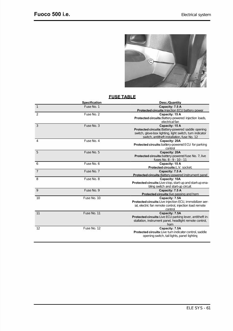
Fuses
The electrical system has twelve fuses divided into
two fuse boxes to protect the different installation
circuits. One of them is inside the battery compart-
ment «A» and the other is at the internal side of
the right footrest «B».To have access, loosen the
screw «C» and remove the plastic cover. The chart
shows the position and specifications of the fuses
in the vehicle.
CAUTION
BEFORE REPLACING A BLOWN FUSE, FIND AND SOLVETHE FAILURE THAT CAUSED IT TO BLOW. NEVER TRYTO REPLACE THE FUSE WITH ANY OTHER MATERIAL(E.G., A PIECE OF ELECTRIC WIRE).
Electrical system Fuoco 500 i.e.
ELE SYS - 60
7/29/2019 Gilera Fuoco 500 i.e. (EN)
http://slidepdf.com/reader/full/gilera-fuoco-500-ie-en 61/329
FUSE TABLE
Specification Desc./Quantity
1 Fuse No. 1 Capacity: 7.5 AProtected circuits:Injection ECU battery power
2 Fuse No. 2 Capacity: 15 AProtected circuits:Battery-powered injection loads,electrical fan
3 Fuse No. 3 Capacity: 15 AProtected circuits:Battery-powered saddle openingswitch, glove-box lighting, light switch, turn indicator
switch, antitheft installation, fuse No. 124 Fuse No. 4 Capacity: 20A
Protected circuits:battery-powered ECU for parkingcontrol
5 Fuse No. 5 Capacity: 20AProtected circuits:battery-powered fuse No. 7, live
fuses No. 8 - 9 - 10 - 116 Fuse No. 6 Capacity: 15 A
Protected circuits:L.V. socket.7 Fuse No. 7 Capacity: 7.5 A
Protected circuits:Battery-powered instrument panel8 Fuse No. 8 Capacity: 10A
Protected circuits:Live stop, start-up and start-up ena-bling switch and start-up circuit.
9 Fuse No. 9 Capacity: 7.5 AProtected circuits:live passing and horn
10 Fuse No. 10 Capacity: 7.5AProtected circuits:Live injection ECU, immobilizer aer-
ial, electric fan remote control, injection load remotecontrol
11 Fuse No. 11 Capacity: 7.5AProtected circuits:Live ECU parking lever, antitheft in-stallation, instrument panel, headlight remote control,
horn12 Fuse No. 12 Capacity: 7.5A
Protected circuits:Live turn indicator control, saddleopening switch, tail lights, panel lighting
Fuoco 500 i.e. Electrical system
ELE SYS - 61

7/29/2019 Gilera Fuoco 500 i.e. (EN)
http://slidepdf.com/reader/full/gilera-fuoco-500-ie-en 62/329
Dashboard
A =Led immobilizer / anti-theft device
B=Speedometer with twin scale (km/h and mph)
C =CLOCK switch
D =Digital display
E =Front suspension locking system warning light
(if available)
F =SET switch
G =Rpm indicator
H =Fuel gauge
I =Warning light for helmet compartment courtesy
light on
L =Engine control telltale light and injection sys-
tem failure warning light
M =Low fuel warning light
N =Engine stop warning light
O=Turn indicator warning light
P =Low oil pressure warning light
Q =Front suspension locking system failure warn-
ing light (if available)R =Warning light for parking brake engaged
Electrical system Fuoco 500 i.e.
ELE SYS - 62

7/29/2019 Gilera Fuoco 500 i.e. (EN)
http://slidepdf.com/reader/full/gilera-fuoco-500-ie-en 63/329
S =High-beam warning light
A =Total odometer gauge
B =«BELT» maintenance icon
C =«SERVICE» maintenance icon
D =Engine coolant temperature indicator
E =Trip odometer (A-B) and ambient temperature gauge (selected with the MODE button)
F =TIME-DATE indicator
G =Low fuel warning light
H =Trip odometer gauge (B)
I =Trip odometer gauge (A)
L =Kilometre - mile indicator
Sealed battery
If the vehicle is provided with a sealed battery, the only maintenance required is the check of its charge
and recharging, if necessary.
These operations should be carried out before delivering the vehicle, and on a six-month basis while
the vehicle is stored in open circuit.
Besides upon pre-delivery it is therefore necessary to check the battery charge and recharge it, if re-
quired, before storing the vehicle and afterwards every six months.
INSTRUCTIONS FOR THE RENEWAL RECHARGE AFTER OPEN-CIRCUIT STORAGE
1) Voltage check up
Before installing the battery on the vehicle, check the open circuit voltage with a standard tester.
- If voltage exceeds 12.60 V, the battery can be installed without any renewal recharge.
- If voltage is below 12.60 V, a renewal recharge is required as explained in 2).
2) Constant voltage battery charge mode
- Constant voltage charge equal to 14.40 to 14.70V
- Initial charge voltage equal to 0.3 to 0.5 for Nominal capacity
- Charge time:10 to 12 h recommended
Minimum 6 h
Maximum 24 h
3) Constant current battery charge mode
- Charge current equal to 1/10 of the battery rated capacity
- Charge time: Maximum 5 h
Fuoco 500 i.e. Electrical system
ELE SYS - 63

7/29/2019 Gilera Fuoco 500 i.e. (EN)
http://slidepdf.com/reader/full/gilera-fuoco-500-ie-en 64/329
Connectors
INJECTION ELECTRONIC CONTROL UNIT
CONNECTOR
1. Injection telltale light LED (Brown-Black)
2. Rpm indicator on instrument panel (Yellow)
3. CAN "L" Line (White-Blue)
4. Lambda probe (-) (White-Green)
5. Live supply (Red-White)
6. Battery-powered (Orange-Black)
7. Immobilizer aerial (Orange-White)
8. Electric fan remote control (Blue-Yellow)
9. Coolant temperature sensor (Sky blue-Green)
10. CAN "H" Line (Pink-White)
11. Lambda probe (+) (Sky blue-Black)
12. Engine stop switch (Green-Black)
13. Engine rpm sensor positive (Red)
14. Fuel injector (Red-Yellow)
15. Engine rpm sensor negative (Brown)
16. Diagnosis (Purple-White)
17. Immobilizer LED (Red-Green)
18. Engine stop switch, coolant temperature sen-
sor (Grey-Green)
19. Not connected
20. Injection load remote control (Black-Purple)
21. Not connected
22. HV coil (Pink-Black)
23. Not connected
24. Start-up enabling switch (Orange-Blue)25. Not connected
26. Ground lead (Black)
Electrical system Fuoco 500 i.e.
ELE SYS - 64
7/29/2019 Gilera Fuoco 500 i.e. (EN)
http://slidepdf.com/reader/full/gilera-fuoco-500-ie-en 65/329
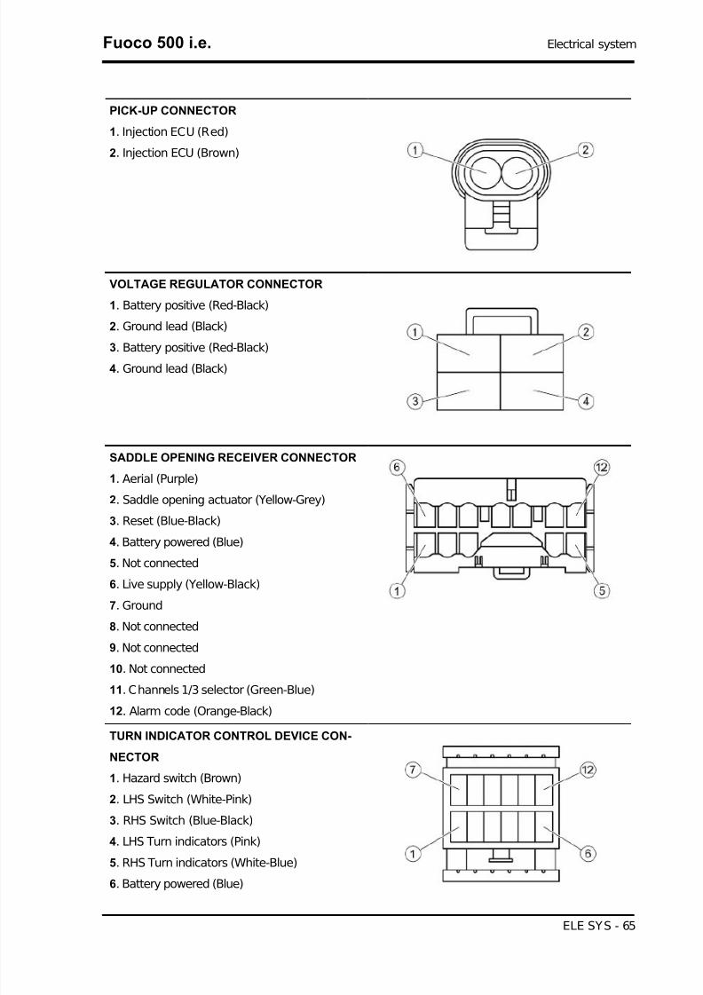
PICK-UP CONNECTOR
1. Injection ECU (Red)
2. Injection ECU (Brown)
VOLTAGE REGULATOR CONNECTOR
1. Battery positive (Red-Black)
2. Ground lead (Black)
3. Battery positive (Red-Black)4. Ground lead (Black)
SADDLE OPENING RECEIVER CONNECTOR
1. Aerial (Purple)
2. Saddle opening actuator (Yellow-Grey)
3. Reset (Blue-Black)4. Battery powered (Blue)
5. Not connected
6. Live supply (Yellow-Black)
7. Ground
8. Not connected
9. Not connected
10. Not connected
11. Channels 1/3 selector (Green-Blue)
12. Alarm code (Orange-Black)
TURN INDICATOR CONTROL DEVICE CON-
NECTOR
1. Hazard switch (Brown)
2. LHS Switch (White-Pink)
3. RHS Switch (Blue-Black)
4. LHS Turn indicators (Pink)
5. RHS Turn indicators (White-Blue)
6. Battery powered (Blue)
Fuoco 500 i.e. Electrical system
ELE SYS - 65

7/29/2019 Gilera Fuoco 500 i.e. (EN)
http://slidepdf.com/reader/full/gilera-fuoco-500-ie-en 66/329
7. Not connected
8. Key-on power (Yellow-Black)
9. Ground lead (Black)
10. Not connected
11. Not connected
12. Not connected
HV COIL CONNECTOR
1. Injection load remote control (Black-Green)
2. Injection ECU (Pink-Black)
ANTI-THEFT DEVICE PRE-INSTALLATION
CONNECTOR
1. Left turn indicators (Pink)
2. Right turn indicators (White-Blue)
3. Ground lead (Black)
4. Battery-powered (Blue)5. Live supply (Yellow-Red)
6. Helmet compartment lighting (Blue-Black)
7. Channels 1/3 selector (Green-Blue)
8. Alarm code (Orange-Black)
FUEL PUMP CONNECTOR
1. Injection load remote control (Black-Green)
2. Not connected
3. Not connected4. Ground lead (Black)
5. Not connected
Electrical system Fuoco 500 i.e.
ELE SYS - 66

7/29/2019 Gilera Fuoco 500 i.e. (EN)
http://slidepdf.com/reader/full/gilera-fuoco-500-ie-en 67/329
INSTRUMENT PANEL CONNECTOR "A"
1. Not connected
2. Not connected
3. Not connected
4. Not connected
5. Instrument panel lighting (Yellow-Black)
6. Battery-powered (Red-Blue)
7. Not connected
8. Not connected
9. Not connected
10. Not connected
11. Ground lead (Black)12. Live supply (Yellow-Red)
INSTRUMENT PANEL CONNECTOR "B"
1. Scooter speed signal (Sky blue)
2. Fuel level indicator (White-Green)
3. Water temperature sensor (Sky blue-Black)
4. Water temperature sensor ground lead (Brown-
White)
5. «MODE» remote button (Green)
6. Oil pressure sensor (Pink-White)
7. Left turn indicator warning light (Pink)
8. Right turn indicator warning light (White-Blue)
9. High-beam warning light (Purple)
10. Boot open warning light (Blue-Black)
11. Rpm sensor (-)
12. Ambient temperature sensor (Yellow-Blue)
13. Ambient temperature sensor ground (White-
Yellow)
14. Engine disabled warning light (Orange-Blue)
15. Immobilizer warning light (Red-Green)
16. Engine check warning light (Brown-Black)
17. Parking brake warning light (Yellow-Grey)
18. Tilt locking activated warning light (Pink-Black)
19. Tilt locking system failure warning light (Grey-
Black)
Fuoco 500 i.e. Electrical system
ELE SYS - 67

7/29/2019 Gilera Fuoco 500 i.e. (EN)
http://slidepdf.com/reader/full/gilera-fuoco-500-ie-en 68/329
20. Live supply from the parking control ECU (Yel-
low-Green)
PARKING CONTROL ECU CONNECTOR
1A. Potentiometer supply (Orange-Blue)
2A. CAN "L" Line (White-Blue)
3A. Warning light supply (Yellow-Green)
4A. Tilt locking activated warning light (Pink-Black)
5A. Tilt locking system failure warning light (Grey-
Black)
6A. Headlight remote control (White-Black)
7A. Potentiometer ground lead, rpm sensor, rider
presence sensor (Yellow)8. Ground (Black)
1B. Live supply (Yellow-Red)
2B. CAN "H" Line (Pink-White)
3B. Left wheel turning sensor (Green)
4B. Right wheel turning sensor (Red)
5B. Potentiometer signal (Green-Blue)
6B. Locking/unlocking switch (Green-Grey)
7B. Horn remote control for alarms (White)
8B. Geared motor (White-Red)
1C. Battery powered (Blue-Red)
2C. Diagnosis (Purple-White)
3C. Locking/unlocking switch (Yellow-Blue)
4C. Calliper sensor (Brown)
5C. Locking/unlocking switch (Purple-Black)
6C. Rider presence sensor (Purple)
7C. Scooter speed signal (Sky blue)
8C. Geared motor (Blue)
Remote seat opening
Electrical system Fuoco 500 i.e.
ELE SYS - 68

7/29/2019 Gilera Fuoco 500 i.e. (EN)
http://slidepdf.com/reader/full/gilera-fuoco-500-ie-en 69/329
Zeroing
- Remove the left side fairing to access the saddle
opening receiver control unit indicated in the pho-
tograph
- Remove the metal terminal and connect it to a
good earth point, or to terminal 7 (black), for at
least 10 seconds.
- In this operation all the remote controls stored in
the control unit will be deleted.
WARNING
THE CONTROL UNIT CAN PROGRAMME UP TO 8 REMOTECONTROLS.
Programming
Follow these steps to program the remote controls:
1. Insert the remote control key to be programmed in the steering lock key block.
2. Turn the key to «ON», press the button on the remote control, release the button, then turn the key
back to «OFF» within four seconds of turning «ON».
3. Wait 1 to 8 seconds.
4. Repeat steps 2 and 3 four more times without removing the key.
The control unit confirms the programming has been successful by opening the saddle.
WARNING
TO STORE THE OTHER REMOTE CONTROLS TO MEMORY (8 MAXIMUM) YOU NEED TO RE-PEAT THE WHOLE PROCEDURE AGAIN. FAILURE TO CARRY OUT THESE OPERATIONSWITHIN THE INDICATED TIMES WILL RESULT IN THE AUTOMATIC CANCELLATION OF THEPROCESS FOR PROGRAMMING THE REMOTE-CONTROLLED KEYS.
WARNING
AVOID PRESSING THE REMOTE CONTROL BUTTON MORE THAN ONCE WHEN FAR AWAYFROM THE SCOOTER. THE SYNCHRONISM BETWEEN THE REMOTE CONTROL AND THE RE-
CEIVER CAN BE IMPAIRED. SHOULD THIS BE THE CASE, REPEAT THE PROGRAMMINGPROCEDURE. DO NOT KEEP THE REMOTE CONTROL IN PLACES WITH TEMPERATURES EX-CEEDING 60° C THE BATTERY WILL RUN DOWN TOO QUICKLY.
Fuoco 500 i.e. Electrical system
ELE SYS - 69

7/29/2019 Gilera Fuoco 500 i.e. (EN)
http://slidepdf.com/reader/full/gilera-fuoco-500-ie-en 70/329
WARNING
TO AVOID BATTERY DISCHARGE, THE SADDLE OPENING REMOTE CONTROL RADIO RE-
CEIVER DEACTIVATES 7 DAYS AFTER THE LAST TIME THE VEHICLE WAS SHUT OFF.JUST TURN THE KEY TO «ON» TO REACTIVATE THE RECEIVER.
Electrical system Fuoco 500 i.e.
ELE SYS - 70

7/29/2019 Gilera Fuoco 500 i.e. (EN)
http://slidepdf.com/reader/full/gilera-fuoco-500-ie-en 71/329
INDEX OF TOPICS
ENGINE FROM VEHICLE ENG VE
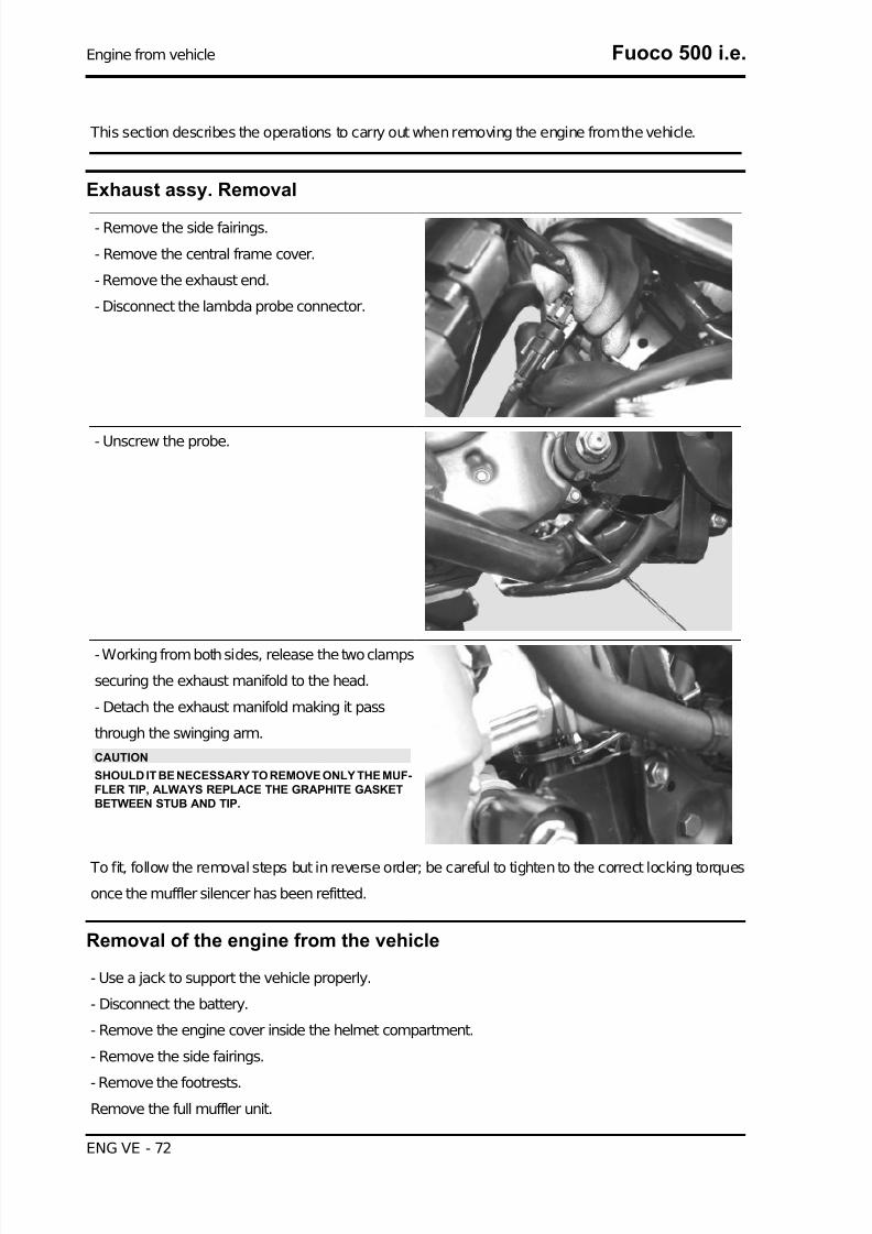
7/29/2019 Gilera Fuoco 500 i.e. (EN)
http://slidepdf.com/reader/full/gilera-fuoco-500-ie-en 72/329
This section describes the operations to carry out when removing the engine from the vehicle.
Exhaust assy. Removal
- Remove the side fairings.
- Remove the central frame cover.
- Remove the exhaust end.
- Disconnect the lambda probe connector.
- Unscrew the probe.
- Working from both sides, release the two clamps
securing the exhaust manifold to the head.
- Detach the exhaust manifold making it pass
through the swinging arm.
CAUTION
SHOULD IT BE NECESSARY TO REMOVE ONLY THE MUF-FLER TIP, ALWAYS REPLACE THE GRAPHITE GASKETBETWEEN STUB AND TIP.
To fit, follow the removal steps but in reverse order; be careful to tighten to the correct locking torques
once the muffler silencer has been refitted.
Removal of the engine from the vehicle
- Use a jack to support the vehicle properly.
- Disconnect the battery.
- Remove the engine cover inside the helmet compartment.
- Remove the side fairings.
- Remove the footrests.
Remove the full muffler unit.
Engine from vehicle Fuoco 500 i.e.
ENG VE - 72

7/29/2019 Gilera Fuoco 500 i.e. (EN)
http://slidepdf.com/reader/full/gilera-fuoco-500-ie-en 73/329
CAUTION
THIS OPERATION MUST BE CARRIED OUT WHEN THE ENGINE IS COLD.
- Remove the rear wheel.
- Remove the bracket supporting the rear brake
callipers and the callipers as well.
- After removing the air filter from the crankcase,
undo the screws fixing the bracket that secures the
rear brake pipes.
- Remove the pipe that feeds coolant into the pump
as shown in the photograph and then empty the
system.
- Remove the engine coolant outlet pipe as indi-
cated.
- Disconnect the fuel delivery pipe from the injector
by removing the screw locking the retainer clamp.
- Disconnect the injector wiring and the throttle
body control unit wiring.
- Remove the coolant outlet pipe from the engine
as indicated.
Fuoco 500 i.e. Engine from vehicle
ENG VE - 73

7/29/2019 Gilera Fuoco 500 i.e. (EN)
http://slidepdf.com/reader/full/gilera-fuoco-500-ie-en 74/329
- Remove the spark plug caps.
- Remove the coolant temperature sensor con-
nector indicated in the photograph.
- Remove the throttle cables from the throttle body
by undoing the nuts indicated in the photograph.
- Remove the negative terminal cable from the
starter motor.
- Remove the positive terminal cable from the
starter motor as shown in the photograph.
- Remove the engine ground lead.
- Disconnect the connectors from the flywheel wir-
ing as shown in the photo.
- Remove the cable from the retaining clip on the
flywheel cover.
Engine from vehicle Fuoco 500 i.e.
ENG VE - 74

7/29/2019 Gilera Fuoco 500 i.e. (EN)
http://slidepdf.com/reader/full/gilera-fuoco-500-ie-en 75/329
Remove the lower screw of the left-hand shock
absorber.
- Remove the engine-swinging arm fixing pin by
undoing the nut and operating on the head of the
pin as shown in the photograph.
- The engine is now free.
When refitting the engine onto the vehicle, carry out the removal operations but in reverse order and
respect the tightening torques shown in the Specifications Chapter.
- Check the engine oil level and if necessary, top it up with the recommended type.
- Fill and bleed the cooling circuit.
- Check accelerator and electric devices for correct functioning.
CAUTION
PAY PARTICULAR ATTENTION TO POSITIONING THE THROTTLE CONTROL TRANSMISSIONPROPERLY.
Fuoco 500 i.e. Engine from vehicle
ENG VE - 75

7/29/2019 Gilera Fuoco 500 i.e. (EN)
http://slidepdf.com/reader/full/gilera-fuoco-500-ie-en 76/329
INDEX OF TOPICS
ENGINE ENG

7/29/2019 Gilera Fuoco 500 i.e. (EN)
http://slidepdf.com/reader/full/gilera-fuoco-500-ie-en 77/329
This section describes the operations to be carried out on the engine and the tools to be used.
Automatic transmission
Transmission cover
- Loosen the 4 fastening screws
- Extract the outside plastic transmission cover.
- Using a screwdriver, remove the driven pulley
axle cover near the bottom of the cap.
- Loosen the driven pulley shaft fastening nut using
a misaligned wrench and prevent the pulley shaft
rotation using a machine hexagon bush.
- Remove the nut and the two washers.
N.B.
DUE TO THE HIGH TIGHTENING TORQUE, USING DIFFER-ENT WRENCHES - SUCH AS A CONVENTIONAL POLYG-
ONAL BUSH - MAY DAMAGE THE HEXAGON OBTAINEDON THE SHAFT OR BREAK THE BUSH ITSELF.
Fuoco 500 i.e. Engine
ENG - 77

7/29/2019 Gilera Fuoco 500 i.e. (EN)
http://slidepdf.com/reader/full/gilera-fuoco-500-ie-en 78/329
- Remove the six M6 screws.
- Remove the four M8 screws.
- Remove the transmission cover.
- Check that the bearing rotates freely, otherwise
replace it.
Air duct
- Remove the transmission cover.
- Unscrew the two screws shown in the figure to
remove the air conveyor.
Locking torques (N*m)
Air conveyor screws 11 ÷ 12
- Remove the external transmission cover.
- Unscrew the 4 fastening screws shown in the fig-
ure to remove the external air conveyor.
Engine Fuoco 500 i.e.
ENG - 78
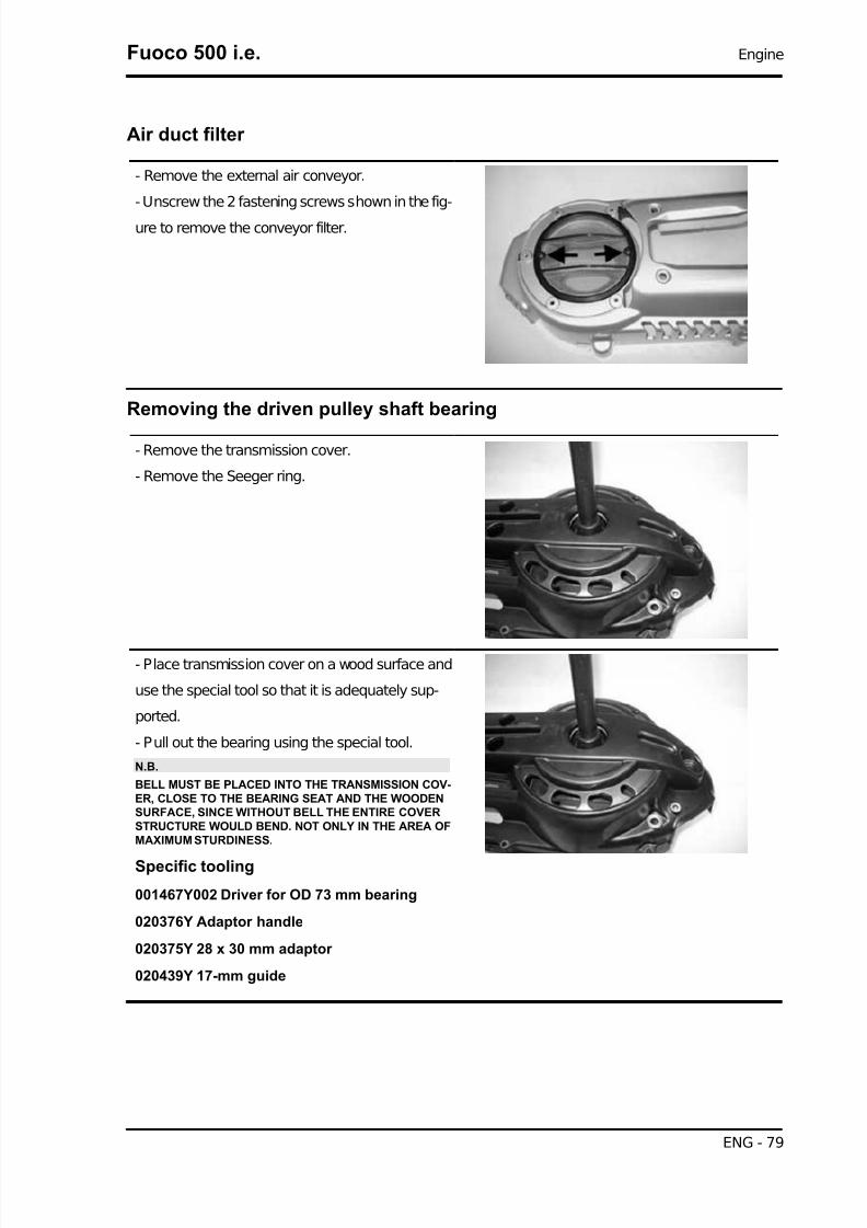
7/29/2019 Gilera Fuoco 500 i.e. (EN)
http://slidepdf.com/reader/full/gilera-fuoco-500-ie-en 79/329
Air duct filter
- Remove the external air conveyor.
- Unscrew the 2 fastening screws shown in the fig-
ure to remove the conveyor filter.
Removing the driven pulley shaft bearing
- Remove the transmission cover.
- Remove the Seeger ring.
- Place transmission cover on a wood surface and
use the special tool so that it is adequately sup-
ported.
- Pull out the bearing using the special tool.
N.B.
BELL MUST BE PLACED INTO THE TRANSMISSION COV-ER, CLOSE TO THE BEARING SEAT AND THE WOODENSURFACE, SINCE WITHOUT BELL THE ENTIRE COVERSTRUCTURE WOULD BEND. NOT ONLY IN THE AREA OFMAXIMUM STURDINESS.
Specific tooling
001467Y002 Driver for OD 73 mm bearing
020376Y Adaptor handle
020375Y 28 x 30 mm adaptor
020439Y 17-mm guide
Fuoco 500 i.e. Engine
ENG - 79

7/29/2019 Gilera Fuoco 500 i.e. (EN)
http://slidepdf.com/reader/full/gilera-fuoco-500-ie-en 80/329
Refitting the driven pulley shaft bearing
- Heat the transmission cover interior using the
heat gun.
N.B.
BE CAREFUL NOT TO OVERHEAT THE COVER AS THISWOULD DAMAGE THE OUTSIDE PAINTED SURFACE.
Specific tooling
020151Y Air heater
- P lace the bearing onto the special tool with a little
grease to prevent it from coming out.
- Install the new bearing using the special tool.
N.B.
PROPERLY SUPPORT THE OUTSIDE COVER TO PRE-VENT DAMAGING THE PAINTED SURFACE.
Specific tooling
020376Y Adaptor handle
020358Y 37x40-mm Adaptor
020439Y 17-mm guide
Baffle roller
Plastic roller
- Check that the roller does not show signs of wear
and that it turns freely.
- Loosen the retaining bolt using a 13 mm spanner.
- Remove the complete roller with bearing.
N.B.
IF THE ROLLER DOES NOT ROTATE FREELY, REPLACETHE COMPLETE ROLLER.
Installation of belt anti-vibration roller
- Install the anti-flapping roller with the lip facing the engine crankcase.
- Tighten the central screw to the prescribed torque.
N.B.
TURN THE DRIVEN AND/OR DRIVING PULLEY UNTIL A CORRECT TENSIONING OF THE BELT
IS OBTAINED.
Locking torques (N*m)
Engine Fuoco 500 i.e.
ENG - 80

7/29/2019 Gilera Fuoco 500 i.e. (EN)
http://slidepdf.com/reader/full/gilera-fuoco-500-ie-en 81/329
Anti-vibration roller screw 16.7 ÷ 19.6
Removing the driven pulley
- Remove the clutch bell.
- Remove the fixed driving half-pulley.- Remove the driven pulley assembly with the belt.
Inspecting the clutch drum
- Check that the clutch bell is not worn or damaged.
- Measure the clutch bell inside diameter.
N.B.
CHECK THE ECCENTRICITY MEASURED, 0.2 MM MAX.
Characteristic
Max. value:
160.5 mm
Standard value:
160.2 mm
Fuoco 500 i.e. Engine
ENG - 81

7/29/2019 Gilera Fuoco 500 i.e. (EN)
http://slidepdf.com/reader/full/gilera-fuoco-500-ie-en 82/329
Removing the clutch
- To remove the clutch with the driven pulley it is
necessary to use the special tool;
- Arrange the tool with the mean pins screwed in
position "E" on the inside;
- Fit the adapter ring to the clutch assembly as
shown in the photograph.
- Install the driven pulley unit onto the tool inserting
the pins into the ventilation holes;
- Move the rear stop screw in abutment against the
fixed driven pulley as shown in the figure.
CAUTION
THE TOOL SHOULD BE FIRMLY SECURED IN A VICE USING THE SPECIAL TOOL. DO NOTTIGHTEN THE REAR SCREW TOO MUCH AS THIS COULD IRRETRIEVABLY DEFORM THE
TOOL.USING THE SPECIAL 55-MM WRENCH, REMOVE THE FASTENING RING NUT.LOOSEN THE TOOL SCREW AND DISASSEMBLE THE DRIVEN PULLEY UNIT, CLUTCH, SPRINGWITH SHEATH.
Specific tooling
020444Y Tool for fitting/ removing the driven pulley clutch
Inspecting the clutch
- Check the thickness of the clutch mass friction material.
Characteristic
Minimum thickness permitted:
1 mm
- The masses must not show traces of lubricants. Otherwise, check the driven pulley unit seals.
N.B.
UPON RUNNING-IN, THE MASSES MUST EXHIBIT A CENTRAL CONTACT SURFACE AND MUSTNOT BE DIFFERENT FROM ONE ANOTHER. VARIOUS CONDITIONS CAN CAUSE THE CLUTCHTO TEAR.
Engine Fuoco 500 i.e.
ENG - 82

7/29/2019 Gilera Fuoco 500 i.e. (EN)
http://slidepdf.com/reader/full/gilera-fuoco-500-ie-en 83/329
- Do not open the masses using tools to prevent a
variation in the return spring load.
Pin retaining collar
- Extract the collar using 2 screwdrivers.
- Remove the 4 guide pins.
- Extract the moving driven half-pulley.
Removing the driven half-pulley bearing
- Check that the bushing is free from wear and
damage; otherwise replace the fixed driven half-
pulley.
- Remove the lock ring using pliers.
Fuoco 500 i.e. Engine
ENG - 83

7/29/2019 Gilera Fuoco 500 i.e. (EN)
http://slidepdf.com/reader/full/gilera-fuoco-500-ie-en 84/329
- Using the special tool inserted through the roller
bearing, pull out the ball bearing.
N.B.
PROPERLY SUPPORT THE PULLEY TO PREVENT DAM-
AGING THE THREADING.
Specific tooling
020376Y Adaptor handle
020456Y Ø 24 mm adaptor
020363Y 20-mm guide
N.B.
IF YOU NEED TO OVERHAUL THE BEARINGS ON AN ASSEMBLED DRIVEN PULLEY UNIT, IT ISNECESSARY TO SUPPORT THE UNIT BY THE BELL
Specific tooling
001467Y002 Driver for OD 73 mm bearing
- Remove the roller bearing using the special tool,
supporting the fixed half-pulley with the bell.
Specific tooling
020376Y Adaptor handle
020375Y 28 x 30 mm adaptor
020364Y 25-mm guide
001467Y002 Driver for OD 73 mm bearing
Inspecting the driven fixed half-pulley
- Check that the belt contact surface is free from
wear.
- Measure the outer diameter of the pulley bushing.
Characteristic
Minimum admissible diameter 49.91 mm
Standard diameter:
50.00 -0.015 -0.035 mm
Engine Fuoco 500 i.e.
ENG - 84

7/29/2019 Gilera Fuoco 500 i.e. (EN)
http://slidepdf.com/reader/full/gilera-fuoco-500-ie-en 85/329
Inspecting the driven sliding half-pulley
- Check that the belt contact surface is free from
wear.
- Remove the 2 inside sealing rings and the 2 out-
side O-rings.
- Measure the movable half-pulley bushing inside
diameter.
Characteristic
Maximum admissible diameter:
50.05 mm
Standard diameter:
50.00 +0.035 0.00 mm
Refitting the driven half-pulley bearing
- Install a new roller bearing using the special tool.
N.B.
PLACE THE BEARING WITH THE WRITINGS AND THE EMBEDDED OIL GUARD FACING OUT-WARDS.
- Properly support the half-pulley to prevent damaging the threading.
If you are working on the driven pulley unit fully assembled, use the special tool.
Specific tooling
020478Y Punch for driven pulley roller casing
001467Y002 Driver for OD 73 mm bearing
- Install a new ball bearing using the special tool.
Specific tooling
020376Y Adaptor handle
020477Y 37 mm adaptor
020363Y 20-mm guide
- Insert the Seeger lock ring.
Fuoco 500 i.e. Engine
ENG - 85

7/29/2019 Gilera Fuoco 500 i.e. (EN)
http://slidepdf.com/reader/full/gilera-fuoco-500-ie-en 86/329
Refitting the driven pulley
- Insert the new oil guards
- Insert the new O-rings
N.B.
O-RINGS ARE OF TWO SIZES. THE LARGE ONE IS INSTALLED ON THE MACHINING END RA-DIUS, AT THE BASE OF THE HALF-PULLEY.
- Install the half-pulley on the bushing being careful
not to damage the top sealing ring during the in-
troduction.
- Make sure the pins and collar are not worn, re-
assemble the pins and collar.
- Using a bent beak greaser, lubricate the driven pulley unit with about 10 gr. of grease, this operation
should be carried out through one of the two holes into the bushing to obtain the exit of the grease from
the opposite hole. This operation is necessary to avoid the presence of grease beyond the O-rings.
Recommended products
AGIP GREASE SM 2 Grease for the C-ring of the tone wheel
Soap-based lithium grease containing NLGI 2 Molybdenum disulphide; ISO-L-XBCHB2, DIN KF2K-20
Inspecting the clutch spring
- Measure the length of the movable driven half-
pulley spring while it is unloaded.
Characteristic
Standard length:
125.5 mmAdmissible limit after use:
120 mm
Engine Fuoco 500 i.e.
ENG - 86

7/29/2019 Gilera Fuoco 500 i.e. (EN)
http://slidepdf.com/reader/full/gilera-fuoco-500-ie-en 87/329
Refitting the clutch
- Prepare the special tool as for removal;
- Preassemble the driven pulley unit with the drive
belt according to its direction of rotation;
- Insert the driven pulley unit, the spring with
sheath and clutch into the tool.
Specific tooling
020444Y Tool for fitting/ removing the driven
pulley clutch
- Compress the spring and insert the clutch on the driven pulley bushing.
N.B.
BE CAREFUL NOT TO DAMAGE THE SHEATH OR THE BUSHING THREADED END.
- Tighten the ring nut by hand and complete the
tightening using the special wrench to the prescri-
bed torque.
Specific tooling
020444Y Tool for fitting/ removing the driven
pulley clutch
Locking torques (N*m)
Clutch ring nut 65 - 75
- To facilitate reassembly on the engine, turn the moving driven pulley and insert the belt onto the smaller
diameter.
Refitting the driven pulley
- Install the driven pulley assembly with belt.
Fuoco 500 i.e. Engine
ENG - 87

7/29/2019 Gilera Fuoco 500 i.e. (EN)
http://slidepdf.com/reader/full/gilera-fuoco-500-ie-en 88/329
Drive-belt
- Check that the driving belt is not damaged.
- Check the width of the belt.
Characteristic
Minimum width
27.5 mm
Overall width
28.7 mm
Removing the driving pulley
- Using a 27 mm wrench, turn the central pulley nut
to horizontally align the central inside holes and
install the special tool.
Specific tooling
020474Y Driving pulley lock wrench
- First fit the 2 retainer clamps of the special tool
onto the pulley so that the splines are completely
engaged.
- Then, insert the tool so as to insert the stud bolts
on the ring into the holes obtained onto the tool
itself.
- Tighten the two tool fixing screws, also manually.
- Loosen the central nut.
- Remove the spring washer and the flat washer.
- Remove the fixed driving half-pulley.
- Remove the bushing connection washer.
Engine Fuoco 500 i.e.
ENG - 88

7/29/2019 Gilera Fuoco 500 i.e. (EN)
http://slidepdf.com/reader/full/gilera-fuoco-500-ie-en 89/329
- Move the belt downwards.
- Suitable support the roller contrast and extract
the movable driving half-pulley with the relevant
bushing and the rear washer, being careful not to
make the rollers come out.
Inspecting the rollers case
- Check that the inside bushings shown in the figure exhibit no signs of abnormal wear and measure
the inside diameter.
CAUTION
DO NOT LUBRICATE OR CLEAN THE BUSHINGS
Characteristic
Maximum admissible diameter:
30.12 mm
Standard diameter:
30.021 mm
- Measure the pulley sliding bushing outside di-
ameter shown in the figure.
Characteristic
Minimum admissible diameter
Ø 29.95 mm
Standard diameter:
Ø 29.959 mm
- Check that the rollers are not damaged or worn.
Characteristic
Minimum admissible diameter
Ø 24.5 mm
Standard diameter:
Ø 24.9 mm
Fuoco 500 i.e. Engine
ENG - 89

7/29/2019 Gilera Fuoco 500 i.e. (EN)
http://slidepdf.com/reader/full/gilera-fuoco-500-ie-en 90/329
- Check the guide shoes for the variator back-plate
are not worn.
- Check the wear of the roller housings and of the
belt contact surfaces on both pulley halves.
Refitting the driving pulley
Installing the roller container
- Install the spacer with the internal chamfer facing
towards the inside.
- Position the rollers on the half-pulley as shown in
the figure.
- The closed side must rest on the inside thrust
face of the roller container.
- Assembly the half-pulley with the roller contrast
plate and sliding blocks.
Engine Fuoco 500 i.e.
ENG - 90
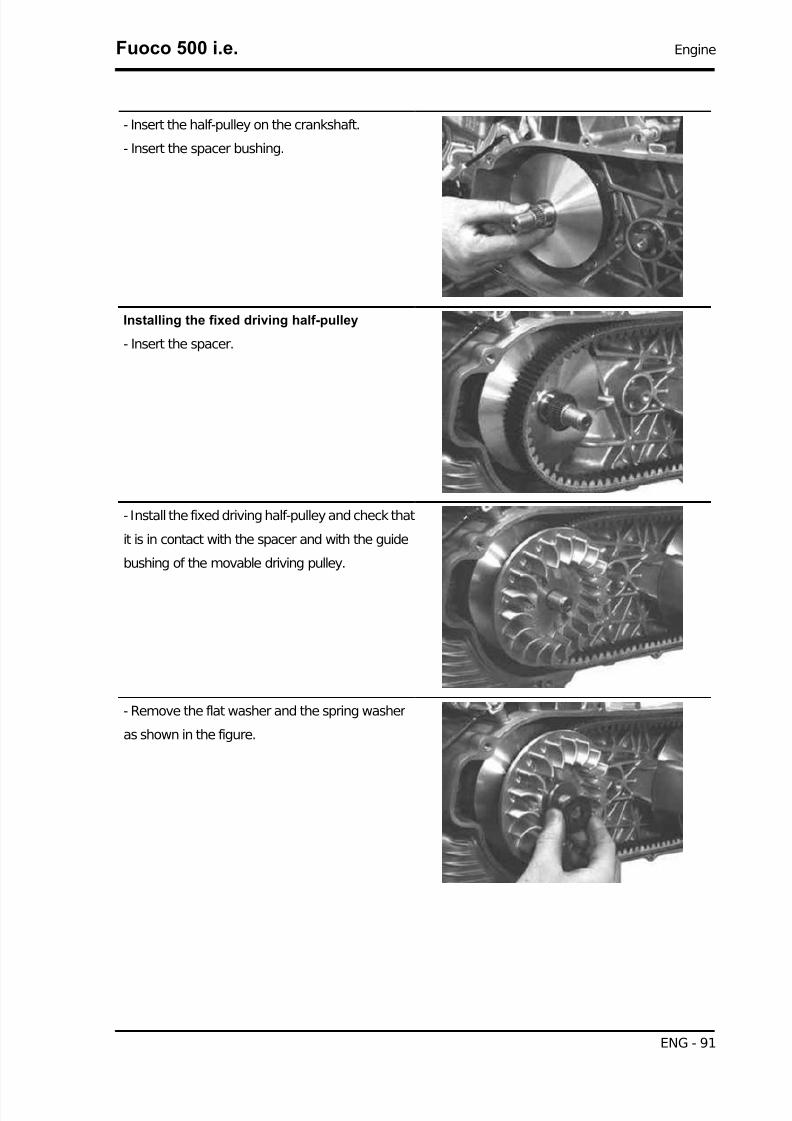
7/29/2019 Gilera Fuoco 500 i.e. (EN)
http://slidepdf.com/reader/full/gilera-fuoco-500-ie-en 91/329
- Insert the half-pulley on the crankshaft.
- Insert the spacer bushing.
Installing the fixed driving half-pulley
- Insert the spacer.
- Install the fixed driving half-pulley and check that
it is in contact with the spacer and with the guide
bushing of the movable driving pulley.
- Remove the flat washer and the spring washer
as shown in the figure.
Fuoco 500 i.e. Engine
ENG - 91
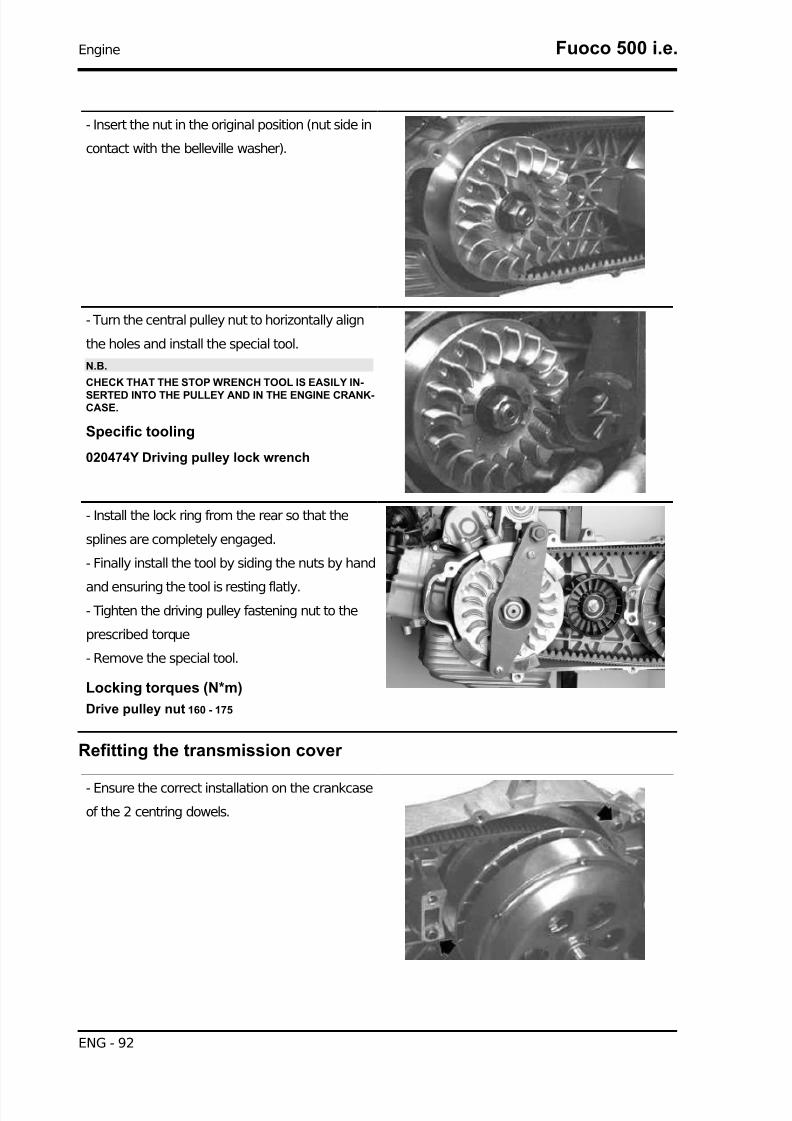
7/29/2019 Gilera Fuoco 500 i.e. (EN)
http://slidepdf.com/reader/full/gilera-fuoco-500-ie-en 92/329
- Insert the nut in the original position (nut side in
contact with the belleville washer).
- Turn the central pulley nut to horizontally align
the holes and install the special tool.
N.B.
CHECK THAT THE STOP WRENCH TOOL IS EASILY IN-
SERTED INTO THE PULLEY AND IN THE ENGINE CRANK-CASE.
Specific tooling
020474Y Driving pulley lock wrench
- Install the lock ring from the rear so that the
splines are completely engaged.
- Finally install the tool by siding the nuts by hand
and ensuring the tool is resting flatly.- Tighten the driving pulley fastening nut to the
prescribed torque
- Remove the special tool.
Locking torques (N*m)
Drive pulley nut 160 - 175
Refitting the transmission cover
- Ensure the correct installation on the crankcase
of the 2 centring dowels.
Engine Fuoco 500 i.e.
ENG - 92

7/29/2019 Gilera Fuoco 500 i.e. (EN)
http://slidepdf.com/reader/full/gilera-fuoco-500-ie-en 93/329
- Insert the transmission cover with the bearing
and install the relevant retainers.
- Lock the four M8 retainers.
Locking torques (N*m)
M8 retainers for transmission cover 23 ÷ 26
- Lock the 7 M6 retainers.
Locking torques (N*m)
M6 retainer 11 ÷ 13
- Insert the washers on the driven pulley shaft.
N.B.
INSERT THE SMALLER WASHER FIRST, THEN THE LARGER ONE.
- Insert the flanged nut.
- Prepare the torque wrench for LHS locking using
a machine hexagon wrench.
- Tighten the driven pulley shaft fastening nut using
an offset wrench.
N.B.
DUE TO THE HIGH TIGHTENING TORQUE, USING DIFFER-ENT WRENCHES - SUCH AS A CONVENTIONAL POLYG-ONAL BUSH - MAY DAMAGE THE HEXAGON OBTAINEDON THE SHAFT OR BREAK THE BUSH ITSELF.
Locking torques (N*m)
Driven pulley nut 92 - 100
- Install the driving pulley shaft cover, positioning
the tooth gap on the lower part with the reference
mark on the transmission crankcase.
N.B.
ENSURE THAT THE AIR INTAKE AND EXHAUST OPENINGS ARE COMPLETELY FREE.
Fuoco 500 i.e. Engine
ENG - 93

7/29/2019 Gilera Fuoco 500 i.e. (EN)
http://slidepdf.com/reader/full/gilera-fuoco-500-ie-en 94/329
- Install the outside plastic transmission cover.
- Tighten the 4 fastening screws to the prescribed
torque.
Locking torques (N*m)
External transmission cover screws 7 ÷ 9
End gear
Removing the hub cover
- Drain the rear hub oil through the oil drainage cap
located under the engine.
-Remove the 7 fastening screws. Remove the hub
cover and the relevant gasket.
Removing the wheel axle
- Remove the countershaft.
- Remove the wheel axis complete with gear.
Engine Fuoco 500 i.e.
ENG - 94
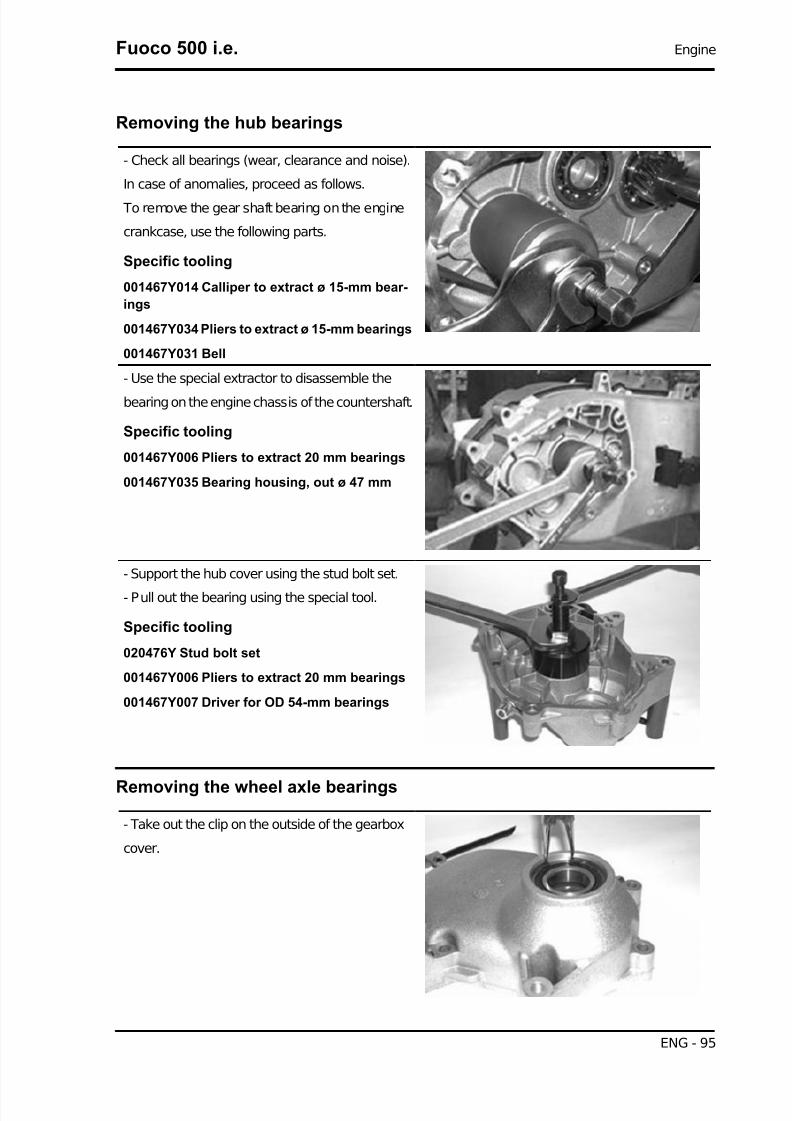
7/29/2019 Gilera Fuoco 500 i.e. (EN)
http://slidepdf.com/reader/full/gilera-fuoco-500-ie-en 95/329
Removing the hub bearings
- Check all bearings (wear, clearance and noise).
In case of anomalies, proceed as follows.
To remove the gear shaft bearing on the engine
crankcase, use the following parts.
Specific tooling
001467Y014 Calliper to extract ø 15-mm bear-
ings
001467Y034 Pliers to extract ø 15-mm bearings
001467Y031 Bell
- Use the special extractor to disassemble the
bearing on the engine chassis of the countershaft.
Specific tooling
001467Y006 Pliers to extract 20 mm bearings
001467Y035 Bearing housing, out ø 47 mm
- Support the hub cover using the stud bolt set.
- Pull out the bearing using the special tool.
Specific tooling
020476Y Stud bolt set
001467Y006 Pliers to extract 20 mm bearings
001467Y007 Driver for OD 54-mm bearings
Removing the wheel axle bearings
- Take out the clip on the outside of the gearbox
cover.
Fuoco 500 i.e. Engine
ENG - 95

7/29/2019 Gilera Fuoco 500 i.e. (EN)
http://slidepdf.com/reader/full/gilera-fuoco-500-ie-en 96/329
- Support the hub cover using the stud bolt set.
- Pull out the bearing using the special tool.
Specific tooling
020476Y Stud bolt set
020376Y Adaptor handle
020477Y 37 mm adaptor
020483Y 30-mm guide
- Remove the oil guard using a screwdriver.
Removing the driven pulley shaft bearing
- If you have to remove the driven pulley shaft, the
relevant bearing and the oil guard, remove the
transmission cover and the clutch unit as descri-
bed in the « Automatic transmission» chapter.
- Extract the driven pulley shaft from its bearing.
- Remove the oil guard using a screwdriver into the
hub gear box.
- Remove the Seeger ring shown in the figure.
- Pull out the driven pulley shaft bearing from the
engine crankcase using the special tool.
Specific tooling
020376Y Adaptor handle
020358Y 37x40-mm Adaptor
020364Y 25-mm guide
Engine Fuoco 500 i.e.
ENG - 96

7/29/2019 Gilera Fuoco 500 i.e. (EN)
http://slidepdf.com/reader/full/gilera-fuoco-500-ie-en 97/329
Inspecting the hub shaft
- Check that the 3 shafts exhibit no wear or defor-
mation on the grooved surfaces, at the bearings
and at the oil seals.
- In case of faults, replace the damaged parts.
Characteristic
Connection diameter for countershaft:
A =diameter 20 - 0.01 -0.02 mmConnection diameter for wheel shaft:
B =diameter 30 - 0.010 -0.023 mm
C =diameter 15 - 0.01 -0.02 mmBearing diameter for driven pulley shaft:
D =diameter 17 - 0.01 -0.02 mm
E =diameter 20 - 0.01 -0.02 mmF =diameter 25 - 0.01 -0.02 mm
Inspecting the hub cover
- Check that the mounting surface is not damaged or deformed.
Fuoco 500 i.e. Engine
ENG - 97

7/29/2019 Gilera Fuoco 500 i.e. (EN)
http://slidepdf.com/reader/full/gilera-fuoco-500-ie-en 98/329
- Check the capacity of the bearings.
In case of faults, replace the hub cover.
Refitting the driven pulley shaft bearing
- Heat the crankcase using the heat gun.
Specific tooling
020151Y Air heater
- Insert the driven pulley shaft bearing until it abuts
against the bottom of the seat using the special
tool.
N.B.
PLACE IT WITH THE BALLS FACING THE HUB (THIS AP-PLIES TO BEARINGS WITH PLASTIC CAGE).
Specific tooling
020376Y Adaptor handle
020360Y 52x55-mm Adaptor
020364Y 25-mm guide
- Heat the intermediate gear bearing seat.
- Insert the intermediate shaft bearing using the
special tool.
N.B.
PLACE IT WITH THE BALLS FACING THE HUB (THIS AP-PLIES TO BEARINGS WITH PLASTIC CAGE).
Specific tooling
020376Y Adaptor handle
020359Y 42x47-mm Adaptor
020363Y 20-mm guide
Engine Fuoco 500 i.e.
ENG - 98

7/29/2019 Gilera Fuoco 500 i.e. (EN)
http://slidepdf.com/reader/full/gilera-fuoco-500-ie-en 99/329
- Heat the gear shaft bearing seat on the crank-
case.
- Insert the gear shaft bearing in the upper crank-
case seat using the special tool.N.B.
PLACE IT WITH THE BALLS FACING THE HUB (THIS AP-PLIES TO BEARINGS WITH PLASTIC CAGE).
Specific tooling
020376Y Adaptor handle
020359Y 42x47-mm Adaptor
020412Y 15-mm guide
- Place the safety lock Seeger ring of the driven
pulley shaft bearing.
N.B.
PLACE IT IN THE POSITION SHOWN IN THE FIGURE.
- Insert the pulley shaft oil guard on the transmis-
sion side.
Refitting the hub cover bearings
- Heat the bearing seats on the cover using the
heat gun.
- Support the hub cover using the stud bolt set.
Specific tooling
020151Y Air heater
020476Y Stud bolt set
Fuoco 500 i.e. Engine
ENG - 99

7/29/2019 Gilera Fuoco 500 i.e. (EN)
http://slidepdf.com/reader/full/gilera-fuoco-500-ie-en 100/329
- Insert the intermediate shaft bearing on the cover
using the special tool.
N.B.
PLACE IT WITH THE BALLS FACING THE HUB (THIS AP-
PLIES TO BEARINGS WITH PLASTIC CAGE).
Specific tooling
020376Y Adaptor handle
020360Y 52x55-mm Adaptor
020363Y 20-mm guide
- Heat the gear shaft bearing seat from the cover
outside.
- Insert the gear shaft bearing on the cover using
the special punch until abutment.
Specific tooling
020376Y Adaptor handle
020360Y 52x55-mm Adaptor
020483Y 30-mm guide
- Replace the snap ring
- Support the hub cover using the stud bolt set.
- Insert the wheel shaft oil guard with the sealing
lip facing the inside of the cover.
- Place the oil guard flush with the crankcase.
Specific tooling
020376Y Adaptor handle
020360Y 52x55-mm Adaptor
020476Y Stud bolt set
Engine Fuoco 500 i.e.
ENG - 100

7/29/2019 Gilera Fuoco 500 i.e. (EN)
http://slidepdf.com/reader/full/gilera-fuoco-500-ie-en 101/329
Refitting the hub bearings
- Place the 3 shafts as shown in the figure.
Refitting the ub cover
- Check the proper position of the centring dowels.
- Install a new gasket.
- Fit the gearbox cover, making sure the breather
pipe is in the correct position.
- Position the 7 set screws, tighten them to the prescribed torque, being careful of the position of the
bands holding the vent tube, and the position of the 3 shortest screws as indicated in the figure.
- Refill with the prescribed oil to the Max. level.
Recommended products
AGIP ROTRA 80W-90 rear hub oil
SAE 80W/90 Oil that exceeds the requirements of API GL3 specifications
Characteristic
Quantity:approx. 250 cc
Locking torques (N*m)
Rear hub cover screws 24 to 27
Fuoco 500 i.e. Engine
ENG - 101

7/29/2019 Gilera Fuoco 500 i.e. (EN)
http://slidepdf.com/reader/full/gilera-fuoco-500-ie-en 102/329
Flywheel cover
- Remove the three bands shown in the figure for
an easier removal of the flywheel cover, remove
the feed hoses and disconnect the return hose
from the pump cover.
N.B.
THE BANDS MUST BE REPLACED. TO REMOVE THEM,OPEN WITH A SCREWDRIVER OR CUT THEM.BE CAREFUL NOT TO DAMAGE THE PLASTIC UNIONS.
Removing the hub cover
- Drain the engine oil by removing the drainage
cap.
- Prepare a suitable container to collect the oil.
- Remove the pre-filter.
- Remove the oil filter using a filter tape or shaped
cup wrench.
Engine Fuoco 500 i.e.
ENG - 102

7/29/2019 Gilera Fuoco 500 i.e. (EN)
http://slidepdf.com/reader/full/gilera-fuoco-500-ie-en 103/329
- Loosen the 14 fastening screws.
- Remove the flywheel cover with the relevant gas-
ket and the cooling system sleeve support.
N.B.THE SCREWS ARE OF 4 DIFFERENT LENGTHS. NOTETHE RELEVANT POSITIONS.
CAUTION
REMOVE THE COVER AVOIDING ANY POSSIBLE INTERFERENCE BETWEEN STATOR ANDROTOR.
CAUTION
BE CAREFUL TO PREVENT SLIPPAGE OF THE BY-PASS VALVE AND OF THE RELEVANTSPRING.
Removing the flywheel cover components
- Loosen the six mounting screws and remove the
water pump cover.
- Remove the by-pass and the relevant spring.
- Remove the oil pump seal.
Fuoco 500 i.e. Engine
ENG - 103

7/29/2019 Gilera Fuoco 500 i.e. (EN)
http://slidepdf.com/reader/full/gilera-fuoco-500-ie-en 104/329
Removing the stator
- Remove the two retaining screws and the cable
guide bracket.
- Unscrew the 3 fastening screws and remove sta-
tor and its wiring.
Inspecting the cover components
- Loosen the two retaining screws and remove the
reed valve support with bulkhead.
- Remove the blow-by reed valve with the relevant
sealing gasket.
Engine Fuoco 500 i.e.
ENG - 104

7/29/2019 Gilera Fuoco 500 i.e. (EN)
http://slidepdf.com/reader/full/gilera-fuoco-500-ie-en 105/329
- Unscrew the fastening screw and remove the gas
outlet union with the relevant O-ring.
- Check that the mounting surface of the crankcase
is not worn or deformed.
- Check that the by-pass valve seat, the torque
limiter and the water pump shaft are free fromwear.
Characteristic
By-pass housing hole diameter:
13.9 mm
Connection diameter for start-up gear shaft:
12 mm
Connection diameter for pump shaft:
8 mm- Check that the oil filter union and matching sur-
face exhibit no deformations or wear.
- Check the condition of the stator and the relevant
cable harness.
Fuoco 500 i.e. Engine
ENG - 105
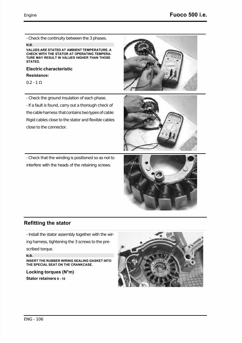
7/29/2019 Gilera Fuoco 500 i.e. (EN)
http://slidepdf.com/reader/full/gilera-fuoco-500-ie-en 106/329
- Check the continuity between the 3 phases.
N.B.
VALUES ARE STATED AT AMBIENT TEMPERATURE. ACHECK WITH THE STATOR AT OPERATING TEMPERA-TURE MAY RESULT IN VALUES HIGHER THAN THOSESTATED.
Electric characteristic
Resistance:
0.2 - 1Ω
- Check the ground insulation of each phase.
- If a fault is found, carry out a thorough check of
the cable harness that contains two types of cable:
Rigid cables close to the stator and flexible cablesclose to the connector.
- Check that the winding is positioned so as not to
interfere with the heads of the retaining screws.
Refitting the stator
- Install the stator assembly together with the wir-
ing harness, tightening the 3 screws to the pre-
scribed torque.
N.B.
INSERT THE RUBBER WIRING SEALING GASKET INTOTHE SPECIAL SEAT ON THE CRANKCASE.
Locking torques (N*m)
Stator retainers 8 - 10
Engine Fuoco 500 i.e.
ENG - 106
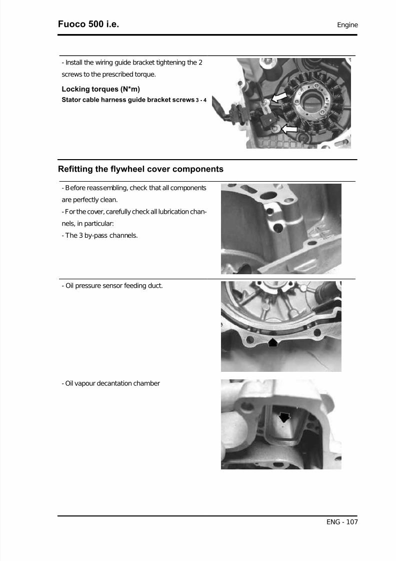
7/29/2019 Gilera Fuoco 500 i.e. (EN)
http://slidepdf.com/reader/full/gilera-fuoco-500-ie-en 107/329
- Install the wiring guide bracket tightening the 2
screws to the prescribed torque.
Locking torques (N*m)
Stator cable harness guide bracket screws 3 - 4
Refitting the flywheel cover components
- Before reassembling, check that all components
are perfectly clean.
- For the cover, carefully check all lubrication chan-
nels, in particular:
- The 3 by-pass channels.
- Oil pressure sensor feeding duct.
- Oil vapour decantation chamber
Fuoco 500 i.e. Engine
ENG - 107

7/29/2019 Gilera Fuoco 500 i.e. (EN)
http://slidepdf.com/reader/full/gilera-fuoco-500-ie-en 108/329
- Temporarily install the distribution timing check
hole cover and the engine oil filling cap/bar.
- Insert the blow-by recovery duct using a new O-
ring.
- Tighten the screws to the prescribed torque.
Locking torques (N*m)
Blow-by recovery duct fixing screws 3 - 4
- Insert the spring and the by-pass piston on the
flywheel cover.
N.B.
LUBRICATE THE BY-PASS VALVE.
- Reinstall the blow-by reed valve using a new
sealing gasket.
- Reinstall the support with head and tighten the
screws to the prescribed torque.
Locking torques (N*m)
Supporting screws with bulkhead 0.3 - 0.4
- Correctly fit a new O-ring, do not allow it to come into contact with grease or oil.
FAILURE TO OBSERVE THIS PRECAUTION WILL IRRETRIEVABLY DEFORM THE O-RING.
- Refit the water pump cover and tighten the 6 fix-
ing screws to the prescribed torque.
Locking torques (N*m)
Pump cover fixing screws: 3 ÷ 4
Engine Fuoco 500 i.e.
ENG - 108

7/29/2019 Gilera Fuoco 500 i.e. (EN)
http://slidepdf.com/reader/full/gilera-fuoco-500-ie-en 109/329
Refitting the flywheel cover
- Install a new oil filter, lubricate the gasket, screw
on and finally tighten to the prescribed torque.
Locking torques (N*m)
Engine oil filter 12 - 16
- Install the supply hose to the cylinder and con-
nect the return hose to the pump cover using 3 new
clamps.
N.B.
TIGHTEN THE CLAMPS USING APPROPRIATE PLIERS,PAYING ATTENTION NOT TO CONSTRICT THE HOSESBUT ALSO TAKING CARE TO TIGHTEN THE CLAMPS SUF-FICIENTLY.
- Install the pre-filter again and insert the engine oil
drain plug, tightening to the prescribed torque.
- Refill the engine with the prescribed type of oil.
Recommended products
AGIP CITY HI TEC 4T Engine oil
SAE 5W-40, API SL, ACEA A3, J ASO MA Syn-
thetic oil
Locking torques (N*m)
Engine oil drainage plug 24 to 30
- Lubricate the intermediate gear seat with torque
limiter on the flywheel cover.
- Align the water pump movement sensor with a
reference and install the flywheel cover as descri-
bed in the Flywheel cover chapter.
Fuoco 500 i.e. Engine
ENG - 109

7/29/2019 Gilera Fuoco 500 i.e. (EN)
http://slidepdf.com/reader/full/gilera-fuoco-500-ie-en 110/329
- Install a new gasket on the engine crankcase.
- Check the presence of the three centring dowels.
- Turn the crankshaft in order to align the counter-
shaft movement sensor with a reference point on
the crankcase (see figure).
- Repeat the alignment for the water pump crank-
shaft using the same reference point on the en-
gine.
N.B.THIS PREPARATION IS USEFUL PARTICULARLY IN THEEVENT OF REPAIRS WITH THE WATER PUMP COVER IN-STALLED.
- Install the flywheel cover on the engine, paying attention to avoid interference between the stator and
rotor.
WARNING
FAILURE TO OBSERVE THIS PRECAUTION MAY RESULT IN DESTRUCTION OF THE CERAMIC
MAGNETS.
- Tighten the 14 retaining bolts of the cover to the
prescribed torque.
N.B.
THE BOLTS HAVE FOUR LENGTHS:- THE 3 SHORTEST ARE INSERTED AS SHOWN IN THEFIGURE.- THE LONGEST IS INSERTED UNDER THE ENGINE OILFILLER PLUG.
Engine Fuoco 500 i.e.
ENG - 110

7/29/2019 Gilera Fuoco 500 i.e. (EN)
http://slidepdf.com/reader/full/gilera-fuoco-500-ie-en 111/329
N.B.
- THE INTERMEDIATE BOLTS FOR THE REMAININGMOUNTING POINTS WITH THE EXCEPTION OF THE BOLTFOR THE MANIFOLD SUPPORT (SHOWN IN THE FIGURE)ARE SLIGHTLY LONGER.
Locking torques (N*m)Flywheel cover screws 11 - 13
Flywheel and starting
- Remove the three bands shown in the figure for
an easier removal of the flywheel cover, removethe feed hoses and disconnect the return hose
from the pump cover.
N.B.
THE BANDS MUST BE REPLACED. TO REMOVE THEM,OPEN WITH A SCREWDRIVER OR CUT THEM.BE CAREFUL NOT TO DAMAGE THE PLASTIC UNIONS.
The starter is sold as a complete part.
Before deciding to replace it, carry out the follow-
ing tests:
1 - Battery
Check the voltage after not running (a few hours):
Voltage >12.5V
Check the density of the electrolyte of each cell:
Bé =30 ÷32
Specific weight: 1.25 - 1.26
YES go to 2 NO go to 3
2 - Make sure the negative terminals (battery neg-
ative and starter negative) are correctly connected
to each other and to the frame.
YES go to 4 NO go to 5
3 - Recharge and if necessary replace the battery.
4 - Connect the diagnostic tester (see chapter "Injection system").
Connect the induction clamp of an ammeter to the positive power supply cable of the starter motor.
Remove the 10A fuse no. 12 (see "fuses" chapter).
Switch in position "ON" with interrupt switch in position "RUN" and side stand raised.
Select the "PARAMETERS" function.
Fuoco 500 i.e. Engine
ENG - 111

7/29/2019 Gilera Fuoco 500 i.e. (EN)
http://slidepdf.com/reader/full/gilera-fuoco-500-ie-en 112/329
Start the engine (so that it cannot move) long enough to measure the rpm and starter absorption.
N.B.
THE DECLARED RPM VALUE IS THAT INDICATED BY THE TESTER, THE RPM READING IS NOTTHE REAL ONE, BUT IS VALID FOR DIAGNOSTIC PURPOSES.
Specific tooling
020680Y Diagnosis Tool
Electric characteristic
Absorption at trailing speed:
80 - 120 A
Revolution speed =
approx. 300-400 rpm
YES go to 6 NO go to 7 NO go to 8 NO go to 9
5 - Restore the connections
6- The values are correct.
Finally carry out a check of the power consumption at idle speed.
Remove the starter motor (see the flywheel and starter system).
Reconnect the earth and positive and perform the test.
Electric characteristic
Current consumption at idle speed:
<40 A
YES go to 10 NO go to 11
7- Low trailing speed
High electrical absorption
Carry out a test of the engine rotation (example: possible melting of the bushes) and if no anomalies
are found, replace the starter motor.
8- Low trailing speed
Low electrical absorption
Repeat the test, bridging the power terminals of the starter remote control switch or even better replacing
them.
Check the new values.
YES go to 12 NO go to 13
Engine Fuoco 500 i.e.
ENG - 112

7/29/2019 Gilera Fuoco 500 i.e. (EN)
http://slidepdf.com/reader/full/gilera-fuoco-500-ie-en 113/329
9 - High trailing speed
Low electrical absorption
The engine turns too freely, check the compression end pressure.
If the values are not correct proceed as follows.
10 - The starter motor works properly.
11 - Check the rotation of the armature.
12 - Replace the starter remote control switch.
13 - Test the battery again and if necessary replace the starter motor.
N.B.
IF THE TRAILING SPEED OF THE CRANKSHAFT IS LOW AND COMBINED WITH STRANGENOISE, CHECK THE FREEWHEEL OF THE TORQUE LIMITER (SEE THE "FLYWHEEL ANDSTARTER SYSTEM" CHAPTER).
STARTER MOTORSpecification Desc./Quantity
Type Mitsuba sm13dPower 0.9 kW
BATTERYSpecification Desc./Quantity
Capacity 14 AhStarting current 125 A
START-UP REMOTE CONTROL SWITCH
Specification Desc./Quantity
Type SEALED
Maximum load 150 A continuous
STARTER TRANSMISSIONSpecification Desc./Quantity
Ring gear and freewheel coaxial to the flywheel. Intermediate gear with built-in torque limiter.
The starter system has a transmission between the motor armature and engine shaft equipped with
freewheel coaxial to the flywheel and torque limiter on the intermediate shaft.
The limiter is calibrated to 10 kgm (100 Nm); this component protects the structure of the engine and
the starter kinematic mechanism in the event of incorrect starting with consequent inverse rotations.
The freewheel is used for a sufficiently silent starting.
The starter control (energised remote control) is slaved to enabling signals by the side stand and the
emergency OFF/RUN switch, which does not allow starting given dangerous conditions.
The starter control circuit is not controlled by the immobilizer system, therefore before insisting on the
starter system, check the consensus of the immobilizer.
In order to check the enabling switches circuit, see the «Electrical system» chapter, whereas to check
the engine shaft control transmission, follow what is described in the «Flywheel and starter system»
chapter.
Removing the starter motor
N.B.
Fuoco 500 i.e. Engine
ENG - 113

7/29/2019 Gilera Fuoco 500 i.e. (EN)
http://slidepdf.com/reader/full/gilera-fuoco-500-ie-en 114/329
THIS OPERATION MAY ALSO BE CARRIED OUT WITH FLYWHEEL COVER ASSEMBLED.
- Loosen the two fastening screws.
- Extract the complete starter motor.
Removing the flywheel magneto
N.B.IF YOU MUST REMOVE THE FLYWHEEL, IT IS NECESSARY TO REMOVE THE CHAIN GUIDESLIDING BLOCK RETAIN PLATE FIRST.
- Unscrew the 3 fastening screws and remove the
chain guide sliding block retain plate and the start-
up rim.
- Align the holes obtained on the flywheel with the
crankcase housing to allow the introduction of the
special tool.
- Tighten the bushing of the flywheel lock tool on
the removing tool threading.
Engine Fuoco 500 i.e.
ENG - 114

7/29/2019 Gilera Fuoco 500 i.e. (EN)
http://slidepdf.com/reader/full/gilera-fuoco-500-ie-en 115/329
- Insert the special tool as shown in the figure,
making sure that the pins are perfectly inserted in-
to the previously aligned holes and that it is per-
fectly abutted and almost flush with the flywheel.
Specific tooling
020472Y Flywheel lock wrench
- Loosen the magneto flywheel fastening nut.
- Remove the special tool and the fastening nut.
- Remove the washer.
- Insert the nut again so as to slightly uncover the
shaft and free the space that was occupied by the
washer.
CAUTIONTHIS OPERATION IS REQUIRED AS THE FLYWHEEL ISSTRONGLY LOCKED; THE CONE DETACHMENT MAYTHEREFORE CAUSE THE ROTOR SLIPPAGE, WITH THECONSEQUENT BREAKAGE OF THE MAGNETS.
Fuoco 500 i.e. Engine
ENG - 115

7/29/2019 Gilera Fuoco 500 i.e. (EN)
http://slidepdf.com/reader/full/gilera-fuoco-500-ie-en 116/329
- Insert the special removing tool.
- Using a 27-mm wrench and a 19-mm bushing,
release the flywheel.
Specific tooling
020467Y Flywheel extractor
- Remove the extractor.
- Remove the nut and extract the flywheel with the
start-up rim.
- Remove the crankshaft key.
- To remove the start-up rim from the freewheel it
is necessary to turn it clockwise and pull it out.
- Remove the freewheel from the flywheel by loos-
ening the 6 fastening screws.
SINCE THE FREEWHEEL MUST BE REMOVED, IT IS AD-VISABLE TO LOOSEN THE 6 FASTENING SCREWS IN
ADVANCE WITH THE FLYWHEEL STILL INSTALLED ONTHE CRANKSHAFT.
Engine Fuoco 500 i.e.
ENG - 116

7/29/2019 Gilera Fuoco 500 i.e. (EN)
http://slidepdf.com/reader/full/gilera-fuoco-500-ie-en 117/329
- The freewheel is coupled to the flywheel with high
precision; if removal is difficult, use 2 screws as
gripping points and as removing tools, if required.
- Extract the intermediate gear provided with tor-
que limiter.
Inspecting the flywheel components
- Check the integrity of the magnets.
- Check that the magnet support cage is free from
deformation or cracks.
- Check that the flywheel splines exhibit no loos-
ening.
Starter gear rim
- Check that there is no wear or abnormal impres-
sions on the "rollers" of the freewheel and on the
surface of the starter ring gear hub.
- Check the hub outside diameter.
Characteristic
Hub outside diameter:
Diameter 45.665 +0.008 +0.005 mm
Fuoco 500 i.e. Engine
ENG - 117

7/29/2019 Gilera Fuoco 500 i.e. (EN)
http://slidepdf.com/reader/full/gilera-fuoco-500-ie-en 118/329
- Check the inside diameter of the bushing of the
starter gearing.
- Check that the toothing is not worn.
Characteristic
Inside diameter of the bushing:
Diameter 27 +0.020 +0.041 mm
N.B.
IF THE FAULTS DISCOVERED AFFECT THE HUB, REPLACE THE STARTER RING GEAR ANDFREEWHEEL.IF ONLY THE BUSHING IS WORN, IT IS POSSIBLE TO REPLACE ONLY THE COMPLETE START-ING RING GEAR. IN THAT CASE, CHECK ALSO THE DIAMETER AND THE SURFACE OF THE
CONNECTION ON THE CRANKSHAFT. IN CASE OR IRREGULARITIES, REPLACE THE CRANK-SHAFT.
Intermediate gear
- Check that the toothing is not worn.
- Check the diameter of the two bearings.
Characteristic
Gear bearing diameter:
12 - 0 0.011 mm
Also check the shaft diameter on the flywheel cov-
er and on the engine crankcase.
Characteristic
Bearing diameter on the flywheel cover
12 +0.034 -0.016 mmBearing diameter on the engine crankcase:
12 +0.034 -0.016 mm
N.B.
THE TORQUE LIMITER IS PROVIDED WITH 4 GEARS THAT HAVE THE FUNCTION OF CLUTCHDRIVE PLATES.
Engine Fuoco 500 i.e.
ENG - 118

7/29/2019 Gilera Fuoco 500 i.e. (EN)
http://slidepdf.com/reader/full/gilera-fuoco-500-ie-en 119/329
Driven plates consist of 4 Belleville springs provi-
ded with grooved profiles; this assembly allows
transmitting torque lower than 10 kg.
In case of incorrect start-up manoeuvres, the lim-
iter prevents any kicks, with consequent reversal
of direction of the crankshaft which would impair
the engine structure.
The limiter assembly cannot be overhauled. In case of irregularities on the toothed discs, replace the
assembly.
Refitting the free wheel
- Make sure the freewheel faying surfaces are in good condition.
- Thoroughly clean the free wheel to remove LOCTITE residue.
- Degrease the threading of the holes in the free wheel and the clamping screws.
- Apply the recommended product to the end of the screws.
Recommended products
Loctite 243 Medium strength threadlock
Medium Loctite 243 threadlock
- Fit the freewheel on the magneto flywheel making
sure that the ground side is in contact with the fly-
wheel itself, i.e. with wheel Seeger ring visible.
- Lock the six clamping screws in criss-cross fash-
ion to the prescribed torque.
Locking torques (N*m)
Screw fixing freewheel to flywheel 13 - 15
- Oil the free wheel "rollers".
Fuoco 500 i.e. Engine
ENG - 119

7/29/2019 Gilera Fuoco 500 i.e. (EN)
http://slidepdf.com/reader/full/gilera-fuoco-500-ie-en 120/329
Refitting the intermediate gear
- Lubricate the gear housing on the engine crank-
case.
- Insert the intermediate gear with torque limiter
- Lubricate the inside bushing and the starter ring
gear hub surface.
- Install the start-up rim on the flywheel turning it
clockwise and inserting at the same time.
Engine Fuoco 500 i.e.
ENG - 120

7/29/2019 Gilera Fuoco 500 i.e. (EN)
http://slidepdf.com/reader/full/gilera-fuoco-500-ie-en 121/329
Refitting the flywheel magneto
- Insert the key on the crankshaft.
- Install the flywheel checking the proper insertion
of the key and engaging the torque limiter gear
with the start-up rim.
- Insert washer and nut on the crankshaft.
- Tighten thoroughly the guide bushing of the fly-
wheel lock tool and loosen by 1/4 turn.
N.B.
FAILURE TO OBSERVE THIS PRECAUTION CAUSES THELOCKING OF THE GUIDE ON THE FLYWHEEL.
Specific tooling
020472Y Flywheel lock wrench
- Align the 2 holes of the flywheel with the case
housing to allow the introduction of the special tool.
Fuoco 500 i.e. Engine
ENG - 121

7/29/2019 Gilera Fuoco 500 i.e. (EN)
http://slidepdf.com/reader/full/gilera-fuoco-500-ie-en 122/329
- Insert the special tool checking that the pins are
perfectly introduced into the seat.
Specific tooling
020472Y Flywheel lock wrench
- Tighten the flywheel lock nut to the prescribed
torque.
Locking torques (N*m)
Flywheel fixing nut 115 - 125
- Install the chain guide retain plate tightening the
3 screws to the prescribed torque.
N.B.
BEFORE TIGHTENING THE SCREWS, MOVE THE START-
UP RIM IN CONTACT WITH THE CRANKCASE AND CHECKTHAT IT IS FREE TO ROTATE IN ANTICLOCKWISE DIREC-TION.
Locking torques (N*m)
Chain guide sliding block retain plate fasten-ing screws 3 ÷ 4
Refitting the starter motor
- Check that the O-ring is in good working order
and lubricate it.
- Insert the starter motor.
- Tighten the 2 fastening screws to the prescribed
torque.
Locking torques (N*m)
Starter screws 11 to 13
Engine Fuoco 500 i.e.
ENG - 122

7/29/2019 Gilera Fuoco 500 i.e. (EN)
http://slidepdf.com/reader/full/gilera-fuoco-500-ie-en 123/329
Cylinder assy. and timing system
- Remove the external and internal transmission
cover.
- Remove the flywheel cover, the flywheel and the
torque limiter.
Removing the intake manifold
- Remove the 3 mounting screws.
- Remove the intake manifold unit.
Removing the rocker-arms cover
- Loosen the 6 special screws with stop and the
relevant rubber gaskets.
- Remove the tappet cover with relevant gasket.
Fuoco 500 i.e. Engine
ENG - 123

7/29/2019 Gilera Fuoco 500 i.e. (EN)
http://slidepdf.com/reader/full/gilera-fuoco-500-ie-en 124/329
Removing the timing system drive
- Turn the engine to close the intake valves.
- Remove the central screw and the valve lifting
device mass stop bell using the special tool.
Specific tooling
020565Y Flywheel lock calliper spanner
- Remove the return spring and the valve lifting
mass with relevant travel end washer.
N.B.
BE CAREFUL NOT TO ALLOW THE WASHER AND SPRINGTO FALL INTO THE ENGINE THROUGH THE CHAIN COM-PARTMENT.
- Align the reference marks on the timing chain rim
with those on the head.
Engine Fuoco 500 i.e.
ENG - 124
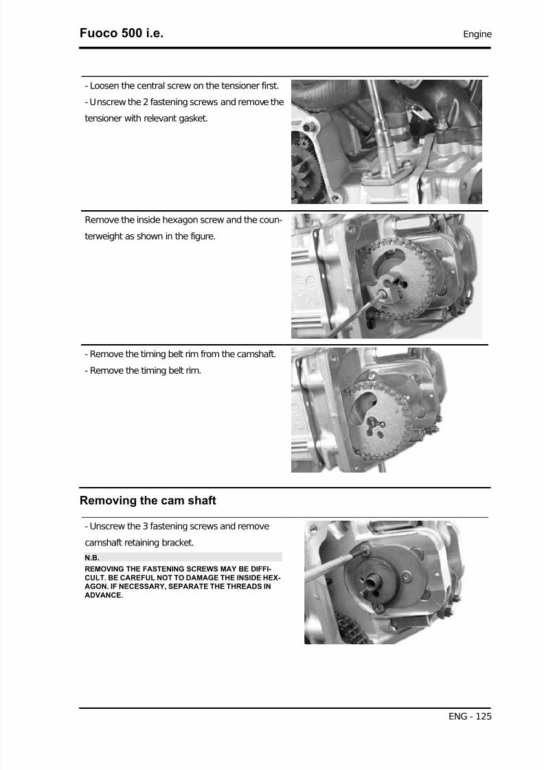
7/29/2019 Gilera Fuoco 500 i.e. (EN)
http://slidepdf.com/reader/full/gilera-fuoco-500-ie-en 125/329
- Loosen the central screw on the tensioner first.
- Unscrew the 2 fastening screws and remove the
tensioner with relevant gasket.
Remove the inside hexagon screw and the coun-
terweight as shown in the figure.
- Remove the timing belt rim from the camshaft.
- Remove the timing belt rim.
Removing the cam shaft
- Unscrew the 3 fastening screws and remove
camshaft retaining bracket.
N.B.
REMOVING THE FASTENING SCREWS MAY BE DIFFI-CULT. BE CAREFUL NOT TO DAMAGE THE INSIDE HEX-AGON. IF NECESSARY, SEPARATE THE THREADS INADVANCE.
Fuoco 500 i.e. Engine
ENG - 125

7/29/2019 Gilera Fuoco 500 i.e. (EN)
http://slidepdf.com/reader/full/gilera-fuoco-500-ie-en 126/329
- Remove the cam shaft.
- Remove pins and rocking levers by the transmis-
sion side holes.
Removing the cylinder head
- Remove the spark plugs.
- Remove the cooling system outlet sleeve with
thermostat.
- Remove the coolant temperature sensor.
N.B.
THE SENSOR CONTROLS BOTH INJECTION AND THE AN-ALOGUE INSTRUMENT ON THE PANEL. TO CHECK THISCOMPONENT, SEE THE INJECTION CHAPTER.
Engine Fuoco 500 i.e.
ENG - 126
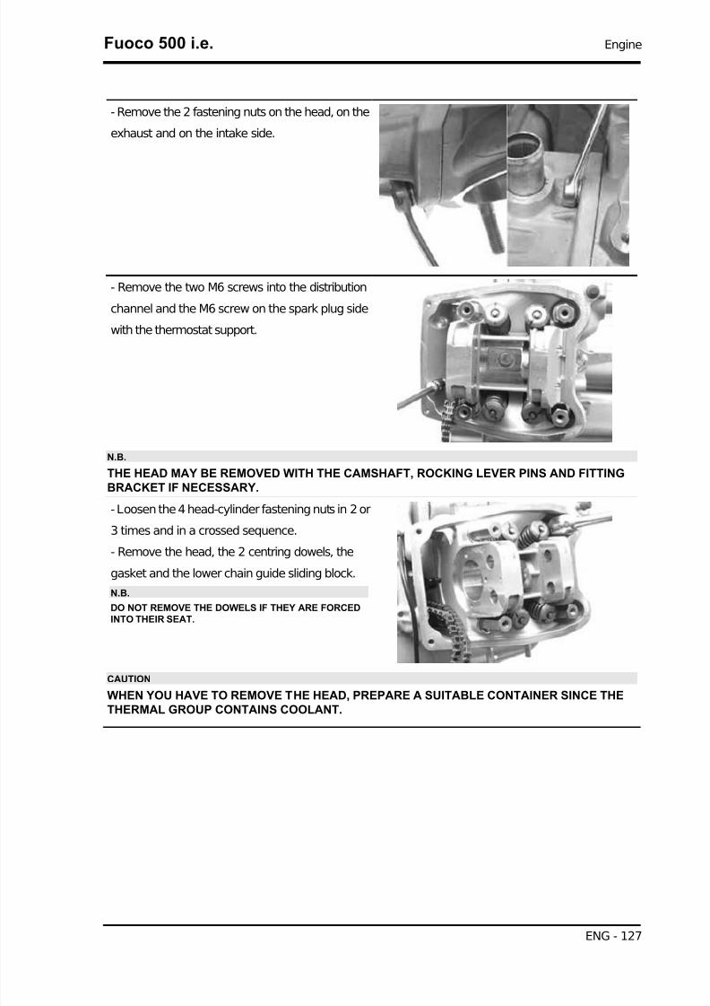
7/29/2019 Gilera Fuoco 500 i.e. (EN)
http://slidepdf.com/reader/full/gilera-fuoco-500-ie-en 127/329
- Remove the 2 fastening nuts on the head, on the
exhaust and on the intake side.
- Remove the two M6 screws into the distribution
channel and the M6 screw on the spark plug side
with the thermostat support.
N.B.
THE HEAD MAY BE REMOVED WITH THE CAMSHAFT, ROCKING LEVER PINS AND FITTINGBRACKET IF NECESSARY.
- Loosen the 4 head-cylinder fastening nuts in 2 or
3 times and in a crossed sequence.
- Remove the head, the 2 centring dowels, the
gasket and the lower chain guide sliding block.
N.B.
DO NOT REMOVE THE DOWELS IF THEY ARE FORCEDINTO THEIR SEAT.
CAUTION
WHEN YOU HAVE TO REMOVE THE HEAD, PREPARE A SUITABLE CONTAINER SINCE THE
THERMAL GROUP CONTAINS COOLANT.
Fuoco 500 i.e. Engine
ENG - 127

7/29/2019 Gilera Fuoco 500 i.e. (EN)
http://slidepdf.com/reader/full/gilera-fuoco-500-ie-en 128/329
Removing the valves
- Using the appropriate tool fitted with an adaptor,
remove the cotters, caps, springs and valves.
Specific tooling
020382Y Valve cotters equipped with part 012
removal tool
020382Y012 bush (valve removing tool)
CAUTION
ARRANGE THE VALVES SO AS TO RECOGNISE THE ORIGINAL POSITION ON THE HEAD (FLY-WHEEL SIDE AND TRANSMISSION SIDE).
- Remove the oil guards using the special tool.
Specific tooling
020431Y Valve oil seal extractor
- Remove the spring supports.
N.B.
BLOW THE SEATS WITH COMPRESSED AIR TO FACILI-TATE THE SPRING SUPPORT REMOVAL.
Engine Fuoco 500 i.e.
ENG - 128

7/29/2019 Gilera Fuoco 500 i.e. (EN)
http://slidepdf.com/reader/full/gilera-fuoco-500-ie-en 129/329
Removing the cylinder - piston assy.
- Remove the timing chain.
- Loosen the fastening screw and remove the
spacer and the tightening sliding block.
N.B.
IT IS ADVISABLE TO MARK THE CHAIN IN ORDER TO EN-SURE THAT THE INITIAL DIRECTION OF ROTATION ISMAINTAINED.
- Extract the cylinder with the relevant gasket and
the centring dowel.
N.B.
THE SECOND CENTRING IS ENSURED BY A PIN SET INTOTHE CYLINDER.
CAUTION
TO PREVENT DAMAGING THE PISTON, SUPPORT ITWHILE REMOVING THE CYLINDER.
- Remove the 2 piston pin locking rings by the spe-
cific housings.
- Extract the pin and remove the piston.
N.B.
USE PAPER OR A CLOTH TO CLOSE THE CYLINDERHOUSING MOUTH ON THE CRANKCASE TO PREVENTSLIPPAGE OF ONE OF THE PIN LOCKING RINGS INTOTHE CASE.
- Remove the piston sealing rings and the oil scra-
per.
CAUTION
NOTE THE ASSEMBLY POSITIONS OF THE LININGS TOPREVENT INVERTING THE POSITION IN CASE OF REUSE.
N.B.
BE CAREFUL NOT TO DAMAGE THE SEALING RINGSDURING REMOVAL.
Fuoco 500 i.e. Engine
ENG - 129

7/29/2019 Gilera Fuoco 500 i.e. (EN)
http://slidepdf.com/reader/full/gilera-fuoco-500-ie-en 130/329
Inspecting the small end
- Using a bore gauge, measure the connecting rod
small end diameter.
N.B.
IF THE CONNECTING ROD SMALL END DIAMETER EX-CEEDS THE STANDARD DIAMETER, EXHIBITS WEAR OROVERHEATING, PROCEED TO REPLACE THE CRANK-SHAFT AS DESCRIBED IN THE CRANKCASE ANDCRANKSHAFT CHAPTER.
Characteristic
Standard diameter:
22 +0.025 +0.015 mm
Inspecting the wrist pin
- Check the pin outside diameter using a micrometer.
Characteristic
Standard diameter:
22 0 -0.004 mm
- Calculate the coupling clearance between pin
and connecting rod end.
Characteristic
Standard clearance:
0.015 ÷0.029 mm
Inspecting the piston
- Measure the diameter of the bearings on the pis-
ton.
Characteristic
Standard diameter:
22 +0.006 +0.001 mm
- Calculate the piston pin coupling clearance.
N.B.
Engine Fuoco 500 i.e.
ENG - 130

7/29/2019 Gilera Fuoco 500 i.e. (EN)
http://slidepdf.com/reader/full/gilera-fuoco-500-ie-en 131/329
THE PIN HOUSINGS HAVE 2 LUBRICATION CHANNELS. FOR THIS REASON, MEASUREMENTMUST BE MADE ACCORDING TO THE PISTON AXIS.
Characteristic
Standard clearance:
0.001 - 0.010 mm
- Measure the outside diameter of the piston, per-
pendicular to the gudgeon pin axis.
- Take the measurement in the position shown in
the figure.
N.B.
REFER TO THE «SPECIFICATIONS» SECTION FOR THESIZES OF THE PISTON AND THE CYLINDER-PISTON COU-PLING CLEARANCES.
CharacteristicA:
10 mm
Piston diameter:
94 mm nominal value
- Using a bore meter, measure the cylinder inner
diameter at a given height according to the direc-
tions shown in the figure.
CharacteristicB:
43 mm
Standard diameter:
94 mm nominal value
- Check that coating is free from flakes.
- Check that the head matching surface exhibits no deformations or wear.
Characteristic
Maximum allowable run-out:
0.05 mm
Fuoco 500 i.e. Engine
ENG - 131
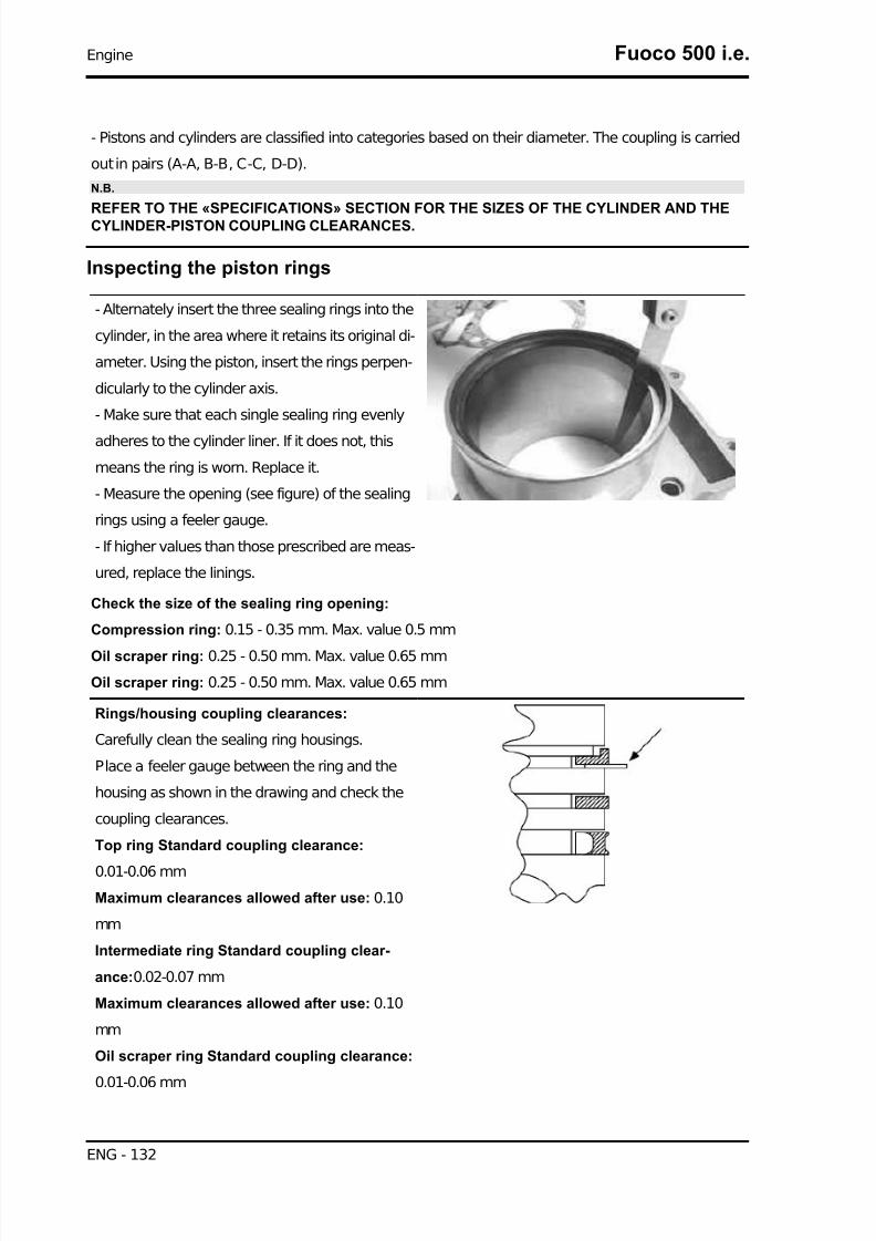
7/29/2019 Gilera Fuoco 500 i.e. (EN)
http://slidepdf.com/reader/full/gilera-fuoco-500-ie-en 132/329
- Pistons and cylinders are classified into categories based on their diameter. The coupling is carried
out in pairs (A-A, B-B, C-C, D-D).
N.B.
REFER TO THE «SPECIFICATIONS» SECTION FOR THE SIZES OF THE CYLINDER AND THECYLINDER-PISTON COUPLING CLEARANCES.
Inspecting the piston rings
- Alternately insert the three sealing rings into the
cylinder, in the area where it retains its original di-
ameter. Using the piston, insert the rings perpen-
dicularly to the cylinder axis.
- Make sure that each single sealing ring evenly
adheres to the cylinder liner. If it does not, this
means the ring is worn. Replace it.
- Measure the opening (see figure) of the sealing
rings using a feeler gauge.
- If higher values than those prescribed are meas-
ured, replace the linings.
Check the size of the sealing ring opening:
Compression ring: 0.15 - 0.35 mm. Max. value 0.5 mm
Oil scraper ring: 0.25 - 0.50 mm. Max. value 0.65 mm
Oil scraper ring: 0.25 - 0.50 mm. Max. value 0.65 mm
Rings/housing coupling clearances:
Carefully clean the sealing ring housings.
Place a feeler gauge between the ring and the
housing as shown in the drawing and check the
coupling clearances.
Top ring Standard coupling clearance:
0.01-0.06 mm
Maximum clearances allowed after use: 0.10
mm
Intermediate ring Standard coupling clear-
ance:0.02-0.07 mm
Maximum clearances allowed after use: 0.10
mm
Oil scraper ring Standard coupling clearance:
0.01-0.06 mm
Engine Fuoco 500 i.e.
ENG - 132

7/29/2019 Gilera Fuoco 500 i.e. (EN)
http://slidepdf.com/reader/full/gilera-fuoco-500-ie-en 133/329
Maximum clearances allowed after use: 0.10
mm
Replace the piston if clearances exceed the max-
imum limits specified in the table.
Removing the piston
- Install piston and wrist pin onto the connecting
rod, aligning the piston arrow the arrow facing to-
wards the exhaust.
- Insert the locking ring into the special tool, with
the opening in the position indicated on the tool.
S =left
D=right
- Place the wrist pin stop ring into position using a
punch
Fuoco 500 i.e. Engine
ENG - 133

7/29/2019 Gilera Fuoco 500 i.e. (EN)
http://slidepdf.com/reader/full/gilera-fuoco-500-ie-en 134/329
- Install the pin lock using the key shown in the
figure.
Specific tooling
020470Y Pin retainers installation tool
N.B.
THE TOOL FOR INSTALLING THE RETAINER RINGS MUST BE USED MANUALLY.
CAUTION
USING A HAMMER MIGHT DAMAGE THE STOPS' HOUSING.
Choosing the gasket
- Provisionally fit the piston into the cylinder, without any base gasket.
- Install a dial gauge on the special tool using the short union, as shown in the figure.
Specific tooling
020475Y Piston position checking tool
- Using an abutment plane, reset the dial gauge
with a preload of a few millimetres.
- Finally fix the dial gauge.
- Check the perfect sliding of the feeler pin.
- Install the tool on the cylinder without changing
the dial gauge position.
- Lock the tool using the original head fixing nuts.
- Rotate the crankshaft up to the TDC (the inver-
sion point of the dial gauge rotation)
- Measure the deviation from the reset value.
- Identify the thickness of the cylinder base gasket to be used for reassembly by the table below. Cor-
rectly identify the cylinder base gasket thickness to keep the correct compression ratio.
- Remove the special tool and the cylinder.
N.B.
Engine Fuoco 500 i.e.
ENG - 134

7/29/2019 Gilera Fuoco 500 i.e. (EN)
http://slidepdf.com/reader/full/gilera-fuoco-500-ie-en 135/329
IF DEVIATIONS (OR RECESSES OR PROJECTIONS) CLOSE TO THE CHANGE OF CATEGORYARE MEASURED, REPEAT THE MEASUREMENT AT THE OPPOSED SIDE. TO DO SO, REPEATTHE TOOL INSTALLATION BY INVERTING ITS POSITION.
Characteristic
Recess / Projection measured 1
- 0.185 - - 0.10
Gasket thickness 1
0.4 ±0.05
Recess / Projection measured 2
- 0.10 - +0.10
Gasket thickness 2
0.6 ±0.05
Recess / Projection measured 3+0.10 ÷+0.185
Gasket thickness 3
0.8 ±0.05
Refitting the piston rings
- Place the scraper ring spring on the piston.
- Install the scraper ring keeping the opening op-
posed to the spring junction and with the writing
"top" facing the piston crown. The chamfered side
of the oil scraper ring should always be facing the
piston crown.
- Fit the second lining with the identification letter
or the writing "top" facing the piston crown. In any
case, the step must be facing opposite the piston
crown.
- Install the first compression lining in the directionimposed by the housing.
- It is advisable to use a fitter to facilitate the in-
stallation of the linings.
N.B.
THE TWO PISTON RINGS ARE MADE WITH A TAPEREDCYLINDRICAL CONTACT CROSS-SECTION. THIS IS TOACHIEVE A BETTER BEDDING.
- Misalign the lining openings at 120° as shown in the figure.
- Lubricate the components with engine oil.
- The engine uses the first compression lining with an L section.
Fuoco 500 i.e. Engine
ENG - 135

7/29/2019 Gilera Fuoco 500 i.e. (EN)
http://slidepdf.com/reader/full/gilera-fuoco-500-ie-en 136/329
Refitting the cylinder
- Insert the cylinder base gasket with the thickness
determined above.
- Using the fork and the ring clamp, fit the cylinder
as shown in the figure.
N.B.
BEFORE FITTING THE CYLINDER, CAREFULLY BLOWTHE LUBRICATION DUCT AND LUBRICATE THE CYLIN-DER LINER. CHECK THE PRESENCE OF THE TWO REF-ERENCE DOWELS.
Specific tooling
020468Y Piston assembly band
020512Y Piston fitting fork
Inspecting the cylinder head
- Using a trued bar and a feeler gauge check that the cylinder head surface is not worn or distorted.
Characteristic
Maximum allowable run-out:
0.1 mm
- In case of faults, replace the head.
- Check the sealing surfaces for the intake and ex-
haust manifold.
- Check that the camshaft and the rocking lever pin
capacities exhibit no wear.
- Check that the head cover surface is not worn.
- Check that the coolant seal plug exhibits no oxi-
dation.
Inspecting the timing system components
- Check that the guide shoe and the tensioner shoe
are not worn out.
- Check that the crankshaft pinion and the cam-
shaft timing gear and crankshaft pinion exhibit no
wear.
In case of wear of the sliding blocks, replace them.
In case of wear of the chain or rim, replace the en-
tire unit.N.B.
Engine Fuoco 500 i.e.
ENG - 136

7/29/2019 Gilera Fuoco 500 i.e. (EN)
http://slidepdf.com/reader/full/gilera-fuoco-500-ie-en 137/329
IF THE CHAIN HAS DAMAGED THE PINION, REPLACE THE CRANKSHAFT AS DESCRIBED INCHAPTER CRANKCASE AND CRANKSHAFT.
Chain tensioner:
- Remove the centre screw with the washer and
the tensioner spring. Check that the one-way
mechanism is not worn.
- Check the condition of the tensioner spring.
- If examples of wear are found, replace the whole
unit.
Inspecting the valve sealings
- Visually inspect the valve sealing surface.
CAUTION
DO NOT REVERSE THE FITTING POSITIONS OF THE VALVES (RIGHT - LEFT).
- If the sealing surface of the valve is found to be
interrupted at one or more points or is not flat, re-
place the valve.
- Insert the valves into the cylinder head.
- Alternatively check the intake and exhaust
valves.
- The test is carried out by filling the manifold with
petrol and checking that the head does not ooze
through the valves when these are just pressed
with the fingers.
Fuoco 500 i.e. Engine
ENG - 137

7/29/2019 Gilera Fuoco 500 i.e. (EN)
http://slidepdf.com/reader/full/gilera-fuoco-500-ie-en 138/329
Inspecting the valve housings
- Clean the valve seats of any carbon residues.
- Using the Prussian blue, check the width of the
impression on the valve seat "V".
Characteristic
Standard value:
1 - 1.3 mm
Admissible limit:
1.6 mm
- If the impression width on the valve seat is larger than the prescribed limits, true the seats with a 45°
mill and then grind.
- In case of excessive wear or damage, replace the head.
Inspecting the valves
- Measure the diameter of the valve stems in the three positions indicated in the diagram.
STANDARD DIAMETER
Specification Desc./Quantity
Intake: 4.987 - 4.972 mmExhaust: 4.975 - 4.960 mm
MINIMUM ADMISSIBLE DIAMETERSpecification Desc./Quantity
Intake: 4.96 mmExhaust: 4.945 mm
- Calculate the clearance between valve and valve guide.
Engine Fuoco 500 i.e.
ENG - 138

7/29/2019 Gilera Fuoco 500 i.e. (EN)
http://slidepdf.com/reader/full/gilera-fuoco-500-ie-en 139/329
- Check the deviation of the valve stem by resting
it on a «V» shaped abutment and measuring the
extent of the deformation with a dial gauge.
Characteristic
Limit values admitted:
0.1 mm
- Check the concentricity of the valve head by ar-
ranging a dial gauge at right angle relative to the
valve head and rotate it on a "V" shaped abutment.
Characteristic
Admissible limit:
0.03 mm
Inspecting the valve stem guide clearance
- After measuring the valve guide diameter and the valve stem diameter, check clearance between
guide and stem.
INTAKESpecification Desc./Quantity
Standard clearance: 0.013 - 0.04 mmAdmissible limit: 0.08 mm
OUTLETSpecification Desc./Quantity
Standard clearance: 0.025 to 0.052 mmAdmissible limit: 0.09 mm
Fuoco 500 i.e. Engine
ENG - 139

7/29/2019 Gilera Fuoco 500 i.e. (EN)
http://slidepdf.com/reader/full/gilera-fuoco-500-ie-en 140/329
STANDARD VALVE LENGTHSpecification Desc./Quantity
Intake: 95.0 ±0.3 mmExhaust: 94.2 ±0.3 mm
- Check that there are no signs of wear on the faying surface with the articulated set screw terminal.
- If no anomalies are found during the above
checks, you can use the same valves. To obtain
better sealing performance, grind the valve seats.
Grind the valves gently with a fine-grained lapping
compound. During the grinding, keep the cylinder
head with the valve axes in a horizontal position.
This will prevent the lapping compound residues
from penetrating between the valve stem and the
guide (see figure).
CAUTION
TO AVOID SCORING THE FAYING SURFACE, DO NOT KEEP ROTATING THE VALVE WHEN NOLAPPING COMPOUND IS LEFT. CAREFULLY WASH THE CYLINDER HEAD AND THE VALVESWITH A SUITABLE PRODUCT FOR THE TYPE OF LAPPING COMPOUND BEING USED.
CAUTION
DO NOT REVERSE THE FITTING POSITIONS OF THE VALVES (RIGHT - LEFT).
Inspecting the springs and half-cones
- Check that the upper and lower supporting spring
washers, the cotters and the oil seal show exhibit
no signs of abnormal wear. Replace a component
when worn.
Engine Fuoco 500 i.e.
ENG - 140

7/29/2019 Gilera Fuoco 500 i.e. (EN)
http://slidepdf.com/reader/full/gilera-fuoco-500-ie-en 141/329
- Measure the unloaded spring length.
Characteristic
Standard length:
44.4 mm
Admissible limit after use:
42.4 mm
Refitting the valves
- Place the valve spring support washers on the
head.
- Alternately insert the 4 oil guards using the spe-
cial tool.
- Lubricate the oil guards and the valve guides.
Specific tooling
020306Y Punch for assembling valve seal
rings
- Fit the valves, the springs and the caps. Using
the appropriate tool with adapter, compress the
springs and insert the cotters in their seats.
Specific tooling
020382Y Valve cotters equipped with part 012
removal tool
020382Y012 bush (valve removing tool)
N.B.
DO NOT CHANGE THE VALVE FITTING POSITION. FIT THE VALVE SPRINGS WITH THE REF-ERENCE COLOUR ON COTTER SIDE (TURNS WITH GREATER PITCH).
Inspecting the cam shaft
- Check that the camshaft bearings exhibit no scores or abnormal wear.
- Using a micrometer, measure the camshaft bearings.
STANDARD DIAMETERSpecification Desc./Quantity
Bearing A Ø: 42 - 0.060 -0.085 mmBearing B diameter: 20 - 0.020 -0.041 mm
Fuoco 500 i.e. Engine
ENG - 141

7/29/2019 Gilera Fuoco 500 i.e. (EN)
http://slidepdf.com/reader/full/gilera-fuoco-500-ie-en 142/329
MINIMUM ADMISSIBLE DIAMETERSpecification Desc./Quantity
Bearing A Ø: 41.910 mmBearing B diameter: 19.940 mm
-Using a gauge, measure the cam height.
STANDARD HEIGHT
Specification Desc./Quantity
intake 33.774 mmdischarge 33.273
ADMISSIBLE LIMITSSpecification Desc./Quantity
intake 33.526 mmdischarge 33.026 mm
Standard axial clearance: 0 - 0.22 mm
Maximum admissible axial clearance: 0.3 mm
- If any of the above dimensions are outside the
specified limits, or there are signs of excessive
wear, replace the defective components with new
ones.
- Check that the retaining plate seat shown in the
figure exhibits no wear.
Engine Fuoco 500 i.e.
ENG - 142

7/29/2019 Gilera Fuoco 500 i.e. (EN)
http://slidepdf.com/reader/full/gilera-fuoco-500-ie-en 143/329
- Check that the automatic valve lifting device cam,
the travel end roller and the rubber abutment on
the containment bell are free from wear.
- Check that the valve lifting spring has not yielded.
- Replace any defective or worn components.
- Check that the rocking lever pins exhibit no scores or wear.
Characteristic
Standard diameter:
13 - 0.010 -0.018 mm
- Measure the inside diameter of each rocker.
Characteristic
Standard diameter:
13 +0.026 +0.015 mm
- Check that the cam contact sliding block and the articulated register cap is free from wear.
- In case of wear, replace the component.
Refitting the head and timing system components
- Insert the chain guide sliding block.
- Insert the two centring dowels between head and
cylinder.
- Install the head gasket.
N.B.
THE FIGURE SHOWS THE INSERTION POSITION OF THE TWO CENTRING DOWELS BETWEENHEAD AND CYLINDER. THE DIRECTION OF INSTALLATION FOR THE GASKET IS FORCED BYTHE DOWELS.
Fuoco 500 i.e. Engine
ENG - 143
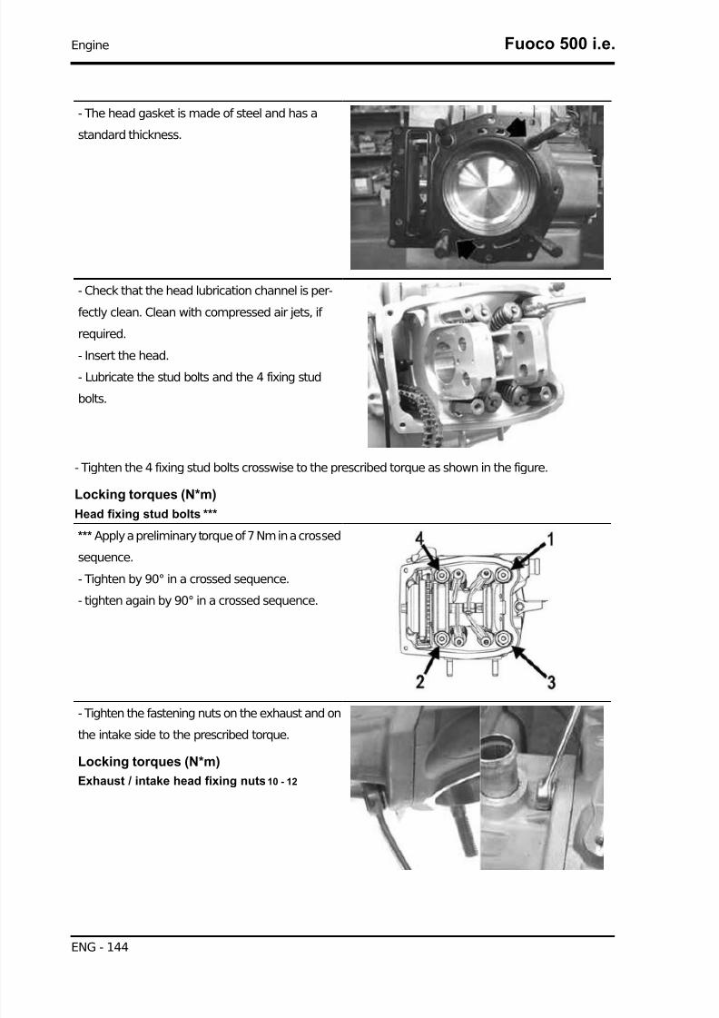
7/29/2019 Gilera Fuoco 500 i.e. (EN)
http://slidepdf.com/reader/full/gilera-fuoco-500-ie-en 144/329
- The head gasket is made of steel and has a
standard thickness.
- Check that the head lubrication channel is per-
fectly clean. Clean with compressed air jets, if
required.
- Insert the head.- Lubricate the stud bolts and the 4 fixing stud
bolts.
- Tighten the 4 fixing stud bolts crosswise to the prescribed torque as shown in the figure.
Locking torques (N*m)
Head fixing stud bolts ***
*** Apply a preliminary torque of 7 Nm in a crossed
sequence.
- Tighten by 90° in a crossed sequence.
- tighten again by 90° in a crossed sequence.
- Tighten the fastening nuts on the exhaust and on
the intake side to the prescribed torque.
Locking torques (N*m)
Exhaust / intake head fixing nuts 10 - 12
Engine Fuoco 500 i.e.
ENG - 144

7/29/2019 Gilera Fuoco 500 i.e. (EN)
http://slidepdf.com/reader/full/gilera-fuoco-500-ie-en 145/329
- Tighten the 3 side screws to the prescribed tor-
que.
Locking torques (N*m)
Head fixing screws 10 - 12
- Install the coolant temperature sensor with the
washer and tighten to the prescribed torque.
CAUTION
FAILURE TO OBSERVE THE TIGHTENING TORQUE CAN
DAMAGE THE SENSOR.
Locking torques (N*m)
Coolant temperature sensor: 10 - 12
- Fit the spark plugs and tighten them to the prescribed torque.
Locking torques (N*m)
Spark plug 12 ÷ 14
- Insert the timing control belt on the crankshaft
according to the initial direction of rotation.
- Install the tensioner shoe with its spacer, tight-
ening the bolt to the prescribed torque, using the
recommended product.
Recommended products
Loctite 243 Medium strength threadlock
Medium Loctite 243 threadlock
Locking torques (N*m)Tensioner sliding block fixing screw 10 - 14
- Insert pins and rocking levers on the flywheel
side.
- Lubricate the two rocking levers through the
holes at the top.
Fuoco 500 i.e. Engine
ENG - 145

7/29/2019 Gilera Fuoco 500 i.e. (EN)
http://slidepdf.com/reader/full/gilera-fuoco-500-ie-en 146/329
- Clean the camshaft by blowing with little com-
pressed air jets, especially the retaining plate
housing.
- Lubricate the 2 shafts.
- Insert the camshaft into the head with the cams
opposite the rocking levers.
- Remove any LOCTITE residues from the screws
fixing the camshaft retaining bracket using a
brush.
- Apply the recommended product to the fixingscrews and tighten to the prescribed torque.
Recommended products
Loctite 243 Medium strength threadlock
Medium Loctite 243 threadlock
- Insert the camshaft retain bracket with visible countersinks and tighten the 3 fastening screws to the
prescribed torque, being careful not to damage the inside hexagon.
Locking torques (N*m)
Camshaft retaining bracket screws: 4 ÷ 6
- Install the intermediate gear with torque limiter,
the flywheel and its cover, as described in Chapter
"Flywheel and start-up system", and in Chapter
"Flywheel cover".
N.B.
FOR MORE CONVENIENCE, INSTALL THE FLYWHEELCOVER WITHOUT THE COOLING SYSTEM SLEEVES.
- Using the TORX wrench, remove the timing
check cap.
Engine Fuoco 500 i.e.
ENG - 146

7/29/2019 Gilera Fuoco 500 i.e. (EN)
http://slidepdf.com/reader/full/gilera-fuoco-500-ie-en 147/329
- Insert the belt on the camshaft control timing rim.
- Insert the timing rim on the camshaft checking
that the references are aligned.
N.B.DURING THE STROKE CHECK, KEEP THE BELT TEN-SIONED BY PRESSING ON THE TIGHTENER COMPART-MENT SIDE.
- Keeping the belt slightly pulled, turn the crank-
shaft using the driving pulley to make the reference
on the magnet support collimate with that on the
flywheel cover.
- Install the counterweight mass.
- Centre using the bell fastening screw.
- Lock the mass fixing screws to the prescribed
torque, using the recommended product.
Recommended products
Loctite 243 Medium strength threadlock
Medium Loctite 243 threadlock
Locking torques (N*m)
Counterweight screw 7 to 8.5
- Remove the central screw.
- Install the valve lifting mass being careful to the
proper positioning of the travel end ring.- Lubricate the mass and de-compressor control
pin.
Fuoco 500 i.e. Engine
ENG - 147

7/29/2019 Gilera Fuoco 500 i.e. (EN)
http://slidepdf.com/reader/full/gilera-fuoco-500-ie-en 148/329
- Install the return spring and load it by about 3/4
turn.
- Turn the engine to move the references to the top
as shown in the figure (intake end).
- Insert the valve lifting device mass stop bell.
- Tighten the retaining screw to the prescribed torque, using the recommended product.
N.B.
THE BELL TIMING IS ENSURED BY THE COUNTERWEIGHT MASS FASTENING SCREW HEAD.
Recommended products
Loctite 243 Medium strength threadlock
Medium Loctite 243 threadlock
- Check that the decompression mass is free and
that it is pulled by the spring.
Locking torques (N*m)
Valve lifter mass stop bell fixing screws 30 - 35
Engine Fuoco 500 i.e.
ENG - 148

7/29/2019 Gilera Fuoco 500 i.e. (EN)
http://slidepdf.com/reader/full/gilera-fuoco-500-ie-en 149/329
- Place the tightener cursor in the rest position,
keeping the retain tab pressed.
- Install a new tightener on the cylinder using a new
gasket.
- Tighten the two fastening screws to the prescri-
bed torque.
Locking torques (N*m)
Tightener fastening screws: 11 to 13
- Insert the spring with the central screw and the
washer.
- Tighten the central screw to the prescribed tor-
que.
Locking torques (N*m)
Tightener screw: 5 to 6
- Place the engine with the valve clearance adjustment timing references aligned with the head.
- Check the clearance between valve and rocking lever using a thickness gauge.
PRESCRIBED CLEARANCE
Specification Desc./Quantity
Inlet 0.15 mm (engine cold)drainage 0.15 mm (engine cold)
- In case different values are found, adjust by loos-
ening the lock nut and use a screwdriver for the set
screw as shown in the figure.
Fuoco 500 i.e. Engine
ENG - 149

7/29/2019 Gilera Fuoco 500 i.e. (EN)
http://slidepdf.com/reader/full/gilera-fuoco-500-ie-en 150/329
Refitting the timing chain
The ignition advance is determined electronically on the basis of parameters known by the control unit.
For this reason it is not possible to interpret the reference values based on the engine rpm.
The ignition advance value is detectable at any time using the diagnostic tester.
It is possible to check whether the ignition advance determined by the injection system matches the
value actually activated on the engine, by means of the stroboscopic light.
Specific tooling
020680Y Diagnosis Tool
020330Y Stroboscopic light to check timing
Proceed as follows:
- Remove the outside transmission cover as de-
scribed in the automatic transmission chapter.
- Remove the TDC reference inspection cap be-
tween flywheel and crankcase cover. See the fly-
wheel cover chapter.
- By the driving pulley, turn the engine to find the
alignment of the references to identify the TDC.
Engine Fuoco 500 i.e.
ENG - 150

7/29/2019 Gilera Fuoco 500 i.e. (EN)
http://slidepdf.com/reader/full/gilera-fuoco-500-ie-en 151/329
- Repeat for the reference between driving pulley
and transmission housing.
- Refit the inspection cap on the flywheel side.
- Connect the diagnostic tester.
- Start the engine.
- Select the «parameters» function in this menu.- Select the stroboscopic light control in the tradi-
tional four-stroke engine position (1 spark, 2 revs).
- Check that the real values of rpm and ignition
advance match those measured using the diag-
nostic tester.
Specific tooling
020680Y Diagnosis Tool
If the values do not match, check:
- distribution timing
- revolution timing sensor
- injection control unit
Refitting the rocker-arms cover
- Check that the gasket is in good working order.
Fuoco 500 i.e. Engine
ENG - 151

7/29/2019 Gilera Fuoco 500 i.e. (EN)
http://slidepdf.com/reader/full/gilera-fuoco-500-ie-en 152/329
- Tighten the two screws indicated in the figure with
«1» and «2» to limit the reciprocal sliding of the
cover surface with the head surface.
- Tighten the remaining 4 screws in a crossed se-
quence (3, 4, 5, 6).
N.B.
CHECK THE PROPER POSITION OF THE GASKET.
Locking torques (N*m)
Tappet cover fixing screws 7 - 9
- Install the transmission cover and the relevant
mesh filter and the outside transmission cover as
described in the "Automatic transmission" chapter.
- Install the cooling system sleeves using new
bands, as described in the "Flywheel cover" chap-
ter.
Refitting the intake manifold
- Install the intake manifold on the engine.
- Insert the 3 fastening screws, one of which with
a support band for the cooling system sleeve, and
tighten to the prescribed torque.
Locking torques (N*m)
Intake manifold screws 11 to 13
Crankcase - crankshaft
- Remove the outside and inside transmission cover and the complete driving pulley as described in
"Automatic transmission".
Engine Fuoco 500 i.e.
ENG - 152

7/29/2019 Gilera Fuoco 500 i.e. (EN)
http://slidepdf.com/reader/full/gilera-fuoco-500-ie-en 153/329
- Remove the flywheel cover with the cooling system sleeves, as described in the "Flywheel cover"
chapter.
- Remove the flywheel with the starting system following the instruction given in "Flywheel and Starting
system".
- Remove the thermal group (cylinder, head, piston) as described in the «Thermal group and timing
system chapter».
- Before opening the crankcase, check the crankshaft axial clearance.
For this purpose, use a plate (e.g. the special tool) and a support with special tool comparator.
Specific tooling
020262Y Crankcase splitting plate
020335Y Magnetic mounting for dial gauge
Characteristic
Standard clearance:
0.10 - 0.50 mm
Admissible increase limit after use:
0.60 mm
- Upper clearances are an indication of wear on the surfaces of the crankshaft casing support.
- To carry out an accurate measurement, measure the clearance in both directions between crankcase
and crankshaft.
Splitting the crankcase halves
- Remove the engine support retain screw on the
flywheel side half-crankcase.
Fuoco 500 i.e. Engine
ENG - 153

7/29/2019 Gilera Fuoco 500 i.e. (EN)
http://slidepdf.com/reader/full/gilera-fuoco-500-ie-en 154/329
- Remove the 14 crankcase coupling screws.
N.B.
THE FASTENING SCREWS ARE OF 3 DIFFERENTLENGTHS. NOTE THEIR CORRECT POSITION.
- Split the crankcases while keeping the crankshaft
inserted on the flywheel side half-crankcase.
- Remove the coupling gasket.
N.B.THE BUSHING SUPPORT CAN BE LEFT IN THE FLY-WHEEL SIDE HALF-CRANKCASE.
Removing the crankshaft
- Before removing the crankshaft, check the timing
with the countershaft. To carry out this check, turn
the crankshaft to align the two holes obtained on
the crankshaft with the hole on the countershaft
control gear.
This is an optimal position also to remove the
crankshaft.
- Remove the crankshaft with the shim adjustment
washer on the flywheel side.
CAUTION
WHILE OPENING THE CRANKCASE AND REMOVING THECRANKSHAFT, CHECK THAT THE SHAFT THREADEDENDS DO NOT INTERFERE WITH THE MAIN BEARINGS.FAILURE TO OBSERVE THIS PRECAUTION CAN DAMAGETHE MAIN BEARING.
Engine Fuoco 500 i.e.
ENG - 154

7/29/2019 Gilera Fuoco 500 i.e. (EN)
http://slidepdf.com/reader/full/gilera-fuoco-500-ie-en 155/329
Removing the oil pump and countershaft con-
trol gear.
- To remove the control gear, loosen the 4 fasten-
ing screws.
Remove the gear only if actually required.
CAUTION
THE SCREWS HAVE A COUNTERSUNK HEAD AND THEIRTHREADING IS LOCKED BY LOCTITE. BE CAREFUL NOTTO DAMAGE THE CONTROL HEXAGON. TO OBTAIN BET-TER RESULTS IT IS PREFERABLE TO USE AN INSIDEHEXAGON SOCKET WRENCH.
Removing the countershaft
- Place the special tool as shown in the figure.
Specific tooling
020479Y Countershaft lock wrench
- Remove the fastening nut with relevant washer.
- Remove the special tool and extract the counter-
shaft with the control gear.
Fuoco 500 i.e. Engine
ENG - 155
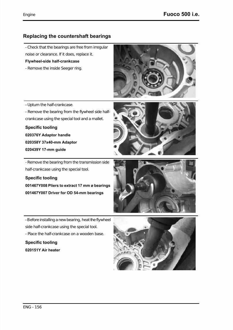
7/29/2019 Gilera Fuoco 500 i.e. (EN)
http://slidepdf.com/reader/full/gilera-fuoco-500-ie-en 156/329
Replacing the countershaft bearings
- Check that the bearings are free from irregular
noise or clearance. If it does, replace it.
Flywheel-side half-crankcase
- Remove the inside Seeger ring.
- Upturn the half-crankcase.
- Remove the bearing from the flywheel side half-
crankcase using the special tool and a mallet.
Specific tooling
020376Y Adaptor handle
020358Y 37x40-mm Adaptor
020439Y 17-mm guide
- Remove the bearing from the transmission side
half-crankcase using the special tool.
Specific tooling
001467Y008 Pliers to extract 17 mm ø bearings
001467Y007 Driver for OD 54-mm bearings
- Before installing a new bearing, heat the flywheel
side half-crankcase using the special tool.
- Place the half-crankcase on a wooden base.
Specific tooling
020151Y Air heater
Engine Fuoco 500 i.e.
ENG - 156

7/29/2019 Gilera Fuoco 500 i.e. (EN)
http://slidepdf.com/reader/full/gilera-fuoco-500-ie-en 157/329
- Insert a new bearing on the special tool after
greasing the guide seat.
- Install the new bearing on the half-crankcase us-
ing the special tool.N.B.
IF A BEARING WITH PLASTIC CAGE IS USED, KEEP THEBALLS VISIBLE FROM THE CRANKCASE INTERNALSIDE.
Specific tooling
020376Y Adaptor handle
020359Y 42x47-mm Adaptor
020439Y 17-mm guide
- Fit the Seeger ring.
- Before installing the new bearing on the trans-
mission side crankcase, heat the seat using the
special tool.
Specific tooling
020151Y Air heater
- Insert a new bearing on the special tool after
greasing the guide seat.
- Install the new bearing on the engine crankcase
using the special tool.
N.B.
IF A BEARING WITH PLASTIC CAGE IS USED, KEEP THEBALLS VISIBLE FROM THE CRANKCASE INTERNALSIDE.
Specific tooling
020376Y Adaptor handle
020359Y 42x47-mm Adaptor
Fuoco 500 i.e. Engine
ENG - 157

7/29/2019 Gilera Fuoco 500 i.e. (EN)
http://slidepdf.com/reader/full/gilera-fuoco-500-ie-en 158/329
020439Y 17-mm guide
Inspecting the crankshaft components
- Check the axial clearance on the connecting rod.
Characteristic
Standard clearance:
0.20 ÷0.40 mm
- Check the connecting rod diametrical clearance.
Characteristic
Standard clearance:
0.046 ÷0.076 mm
-Check the surfaces that limit the axial free-play
are not scored and measure the width of the crank-
shaft between these surfaces, as shown in the
diagram.
N.B.
BE CAREFUL NOT TO LET THE MEASUREMENT BE AF-FECTED BY THE UNIONS WITH THE CRANKSHAFT ENDS.
Characteristic
Standard dimensions:
63.6 - 63.45 mmCAUTION
THE CRANKSHAFT CAN BE REUSED WHEN THE WIDTH FALLS WITHIN THE STANDARD VAL-UES AND THE SURFACES ARE FREE FROM SCRATCHES.
Shimming
- Check the overall height of the crankshaft - shoulders - gear assembly.
Characteristic
Standard thickness:
71.804 - 72.000 mm
- Check that shim adjustment is free from scratches.
N.B.
Engine Fuoco 500 i.e.
ENG - 158

7/29/2019 Gilera Fuoco 500 i.e. (EN)
http://slidepdf.com/reader/full/gilera-fuoco-500-ie-en 159/329
IN CASE OF NEW UTILISATION, MAINTAIN THE FIRST FITTING POSITION.
Specific tooling
020074Y Support base for checking crankshaft alignment
- If the crankshaft - crankcase axial clearance is higher than the standard value and the crankshaft
exhibits no irregularity, the problem is caused by wear or by a wrong machining on the engine crankcase.
- Check the diameters of both bearings of the
crankshaft in accordance with the axes and surfa-
ces shown in the figure. Half shafts are classified
into two categories, Cat 1 and Cat. 2. Refer to the
chart below.
STANDARD DIAMETER
Specification Desc./Quantity
Cat. 1 40.010 ÷40.016Cat. 2 40.016 ÷40.022
Inspecting the crankshaft alignment
- Install the crankshaft on the support and measure the displacement at the 4 points shown in the figure.
Specific tooling
020074Y Support base for checking crankshaft alignment
MAX ADMISSIBLE DISPLACEMENT:Specification Desc./Quantity
A =0.15 mmB =0.01 mmC =0.01 mmD =0.10 mm
- Check that the driving shaft cone, the tab seat, the oil seal capacity, the toothed gear and the threaded
tangs are in good working order.
- In case of failures, replace the crankshaft.
Fuoco 500 i.e. Engine
ENG - 159

7/29/2019 Gilera Fuoco 500 i.e. (EN)
http://slidepdf.com/reader/full/gilera-fuoco-500-ie-en 160/329
N.B.
MAIN BEARINGS CANNOT BE MODIFIED.
The connecting rod cannot be replaced. To check the connecting rod small end diameter, see chapter
"Thermal group and timing system".
- When cleaning the crankshaft, be careful to prevent any impurity from entering into the shaft lubrication
hole.
N.B.
IN CASE OF REPLACEMENT OF A CRANKSHAFT CONSISTING OF TWO HALF-SHAFTS OF DIF-FERENT CATEGORY, REPLACE THE TWO HALF-CRANKCASES AS WELL, COUPLING THE TWOCOMPONENTS (SHAFT AND CRANKCASE) WITH THE SAME CATEGORY.
- To check the gearing of the crankshaft, see sec-
tion "Thermal group and timing system".
See also
Cylinder assy. and timing system
Inspecting the crankcase halves
- Before proceeding to check the crankcase
halves, thoroughly clean all surfaces and oil ducts.
- For the transmission-side half-crankcase, special
attention should be given to the bushings, to the
cooling jet on the transmission side (see figure)
and to the lubrication duct.
N.B.
THE JET IS FED THROUGH THE MAIN BUSHINGS. PROP-ER OPERATION OF THIS COMPONENT IMPROVES THEPISTON TOP COOLING. CLOGGING HAS EFFECTS THATARE DIFFICULT TO DETECT (PISTON TEMPERATURE IN-CREASE). FAILURE OR LEAK CAN CONSIDERABLY DE-CREASE THE MAIN BUSHING AND CONNECTING RODLUBRICATION PRESSURE.
Engine Fuoco 500 i.e.
ENG - 160

7/29/2019 Gilera Fuoco 500 i.e. (EN)
http://slidepdf.com/reader/full/gilera-fuoco-500-ie-en 161/329
- For the flywheel side half-crankcase, special at-
tention should be given to the lubrication channels
for the main bearings and to the compartment and
the channels for the oil pump, as well as to the duct
for the by-pass located on the flywheel cover.
N.B.
AS ALREADY DESCRIBED IN THE "LUBRICATION" CHAP-TER, IT IS ESPECIALLY IMPORTANT THAT THE BY-PASSHOUSING ON THE FLYWHEEL COVER IS FREE FROMWEAR THAT MAY IMPAIR THE PROPER SEALING OF THELUBRICATION PRESSURE ADJUSTMENT PISTON. THEHEAD LUBRICATION CHANNEL IS EQUIPPED WITH ASHUTTER JET; THIS GIVES A "LOW PRESSURE" HEADLUBRICATION. THIS CHOICE WAS MADE TO REDUCETHE OIL TEMPERATURE IN THE SUMP.
The jet clogging impairs the head lubrication and the timing mechanisms.
A jet failure causes a decrease in the main bearing and connecting rod lubrication pressure.
- Check that the surfaces exhibit no dents or deformations, with special attention to the crankcase
coupling and the crankcase-cylinder surfaces.
- Any defects in the crankcase gasket or matching surfaces (see Flywheel cover coupling) can cause
pressurised oil leaks, thereby affecting the connecting rod and main bearing lubrication pressure.
- Check the main bearing seats that limit axial clearance in the crankshaft exhibit no wear. For the
dimensional check, refer to the instructions about checking the axial clearance and the dimensions on
the crankshaft
Inspecting the crankshaft plain bearings
- To obtain a good bushing lubrication it is neces-
sary to have both an optimal lubricating pressure
(4 bar) and a good oil flow rate; the bushings must
be correctly positioned so as not to obstruct the oil
supply channels.
- The main bushings are comprised of two half-
bearings, one with holes and channels for lubrica-
tion whereas the other is solid.
- The solid half-bearing is intended to stand the thrusts caused by combustion, and for this reason it is
arranged opposite the cylinder.
- To prevent obstructions in the oil feeding channels, the matching surface of the two half-bearings must
be perfectly perpendicular to the cylinder axis, as shown in the figure.
- The oil feeding channel section is also affected by the bushings driving depth compared with the
crankshaft axial clearance of the limiting surface.
N.B.TO KEEP THE BUSHINGS ON THE CRANKCASE IN SUCH POSITION, DRIVING IS FORCED ONCAST-IRON RINGS INSERTED IN THE CASTING OF BOTH CRANKCASE HALVES.
Fuoco 500 i.e. Engine
ENG - 161

7/29/2019 Gilera Fuoco 500 i.e. (EN)
http://slidepdf.com/reader/full/gilera-fuoco-500-ie-en 162/329
- Check the inside diameter of the main bushings
in the three directions indicated in the diagram.
- Repeat the measurements for the other bushing
half. see diagram.N.B.
DO NOT TAKE THE MEASUREMENT ON THE TWO HALF-SHELL COUPLING SURFACE SINCE THE ENDS ARE RE-LIEVED TO ALLOW BENDING DURING THE DRIVINGOPERATION.
Before assembling, check that the clearance between the engine crankcase bushing and the crankshaft
is within the predetermined limits.
Characteristic
Crankshaft-bushing maximum clearance admitted:
0.08 mm
- The standard bushing diameter after driving is variable on the basis of a coupling selection.
- The crankcase bushing seats are classified into 3 categories while the crankshaft ones, into 2 cate-
gories.
- Bushings are subdivided into 4 categories according to their thickness (see the table).
CHECK THE BENCH BUSH
Name Description Dimensions Initials Quantity
Type A - Red 1.971 ÷1.974 Type B - Blue 1.974 ÷1.977 Type C - Yellow 1.977 ÷1.980 Type D - Green 1.980 ÷1.983
Coupling chart
The following kinds of bushings indicated in the table must be used according to the kind of coupling
between the crankshaft and the crankcase.
Engine Fuoco 500 i.e.
ENG - 162

7/29/2019 Gilera Fuoco 500 i.e. (EN)
http://slidepdf.com/reader/full/gilera-fuoco-500-ie-en 163/329
KEY
X =Crankshaft category
Y =Crankcase half-shell category
A =Red
B =Blue
C =Yellow
D =Green
In case of breakdown, crankcases are together with bushings and are classified according to the centre
to centre distance of the countershaft. Find below the possible couplings.
- Complete FC1 type crankcase equipped with bushings for housing a category 1 crankshaft and a
countershaft with centre to centre distance A.
- Complete FC2 type crankcase equipped with bushings for housing a category 2 crankshaft and a
countershaft with centre to centre distance A.- Complete FC3 type crankcase equipped with bushings for housing a category 1 crankshaft and a
countershaft with centre to centre distance B.
- Complete FC4 type crankcase equipped with bushings for housing a category 2 crankshaft and a
countershaft with centre to centre distance B.
N.B.
THE CRANKSHAFT CATEGORY IS STAMPED ON THE COUNTERWEIGHT SHOULDER.
A spare crankcase cannot be combined with a driving shaft with mixed categories. Spare shafts have
half-shafts of the same category.
N.B.TO REPLACE THE HALF-SHAFTS, REMOVE THE COUNTERSHAFT BEARINGS AS DESCRIBEDABOVE. REMOVE THE COMPLETE DRIVEN PULLEY AND THE ANTI-FLAPPING ROLLER FROM
Fuoco 500 i.e. Engine
ENG - 163

7/29/2019 Gilera Fuoco 500 i.e. (EN)
http://slidepdf.com/reader/full/gilera-fuoco-500-ie-en 164/329
THE TRANSMISSION SIDE HALF-CRANKCASE, AS DESCRIBED IN CHAPTER "AUTOMATICTRANSMISSION", AND THE HUB COVER WITH THE RELEVANT GEARS AND BEARINGS ASDESCRIBED IN CHAPTER "FINAL REDUCTION".
Countershaft
- Using a micrometer, measure the 2 bearings of
the countershaft as shown in the figure.
Characteristic
Standard diameter:
17 - 0.01 - 0.02 mm
- Check that the water pump drive is not worn.
Refitting the crankshaft
- Check that the oil pump and countershaft control gear are free from deformations or dents. Replace,
if required.
N.B.
IF YOU HAVE TO REPLACE THE OIL PUMP AND COUNTERSHAFT CONTROL GEAR IT IS NEC-ESSARY TO REPLACE THE COUNTERSHAFT GEAR AS WELL.
- Before installing the gear on the crankshaft, care-
fully clean the two matching surfaces removing
any residues of LOCTITE from the holes using a
brush.
Blow with compressed air and degrease the mounting holes on both surfaces to make the new LOCTITE
grip.
Apply the recommended product to the holes again.
Recommended products
Loctite 243 Medium strength threadlock
Medium Loctite 243 threadlock
- Repeat the same procedure for the 4 fastening screws.
- Insert the control gear on the crankshaft with the hole countersink visible.
- Tighten the 4 fastening screws to the prescribed torque.
N.B.
Engine Fuoco 500 i.e.
ENG - 164
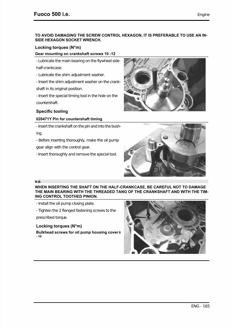
7/29/2019 Gilera Fuoco 500 i.e. (EN)
http://slidepdf.com/reader/full/gilera-fuoco-500-ie-en 165/329
TO AVOID DAMAGING THE SCREW CONTROL HEXAGON, IT IS PREFERABLE TO USE AN IN-SIDE HEXAGON SOCKET WRENCH.
Locking torques (N*m)
Gear mounting on crankshaft screws 10 -12
- Lubricate the main bearing on the flywheel side
half-crankcase.
- Lubricate the shim adjustment washer.
- Insert the shim adjustment washer on the crank-
shaft in its original position.
- Insert the special timing tool in the hole on the
countershaft.
Specific tooling
020471Y Pin for countershaft timing
- Insert the crankshaft on the pin and into the bush-
ing.
- Before inserting thoroughly, make the oil pump
gear align with the control gear.
- Insert thoroughly and remove the special tool.
N.B.
WHEN INSERTING THE SHAFT ON THE HALF-CRANKCASE, BE CAREFUL NOT TO DAMAGETHE MAIN BEARING WITH THE THREADED TANG OF THE CRANKSHAFT AND WITH THE TIM-ING CONTROL TOOTHED PINION.
- Install the oil pump closing plate.
- Tighten the 2 flanged fastening screws to the
prescribed torque.
Locking torques (N*m)
Bulkhead screws for oil pump housing cover 8- 10
Fuoco 500 i.e. Engine
ENG - 165

7/29/2019 Gilera Fuoco 500 i.e. (EN)
http://slidepdf.com/reader/full/gilera-fuoco-500-ie-en 166/329
Refitting the crankcase halves
- Remove the oil guard from the transmission side
half-crankcase using a screwdriver.
- Install a new oil guard after lubricating it, using
the special tool, arranging it at a 0.5 mm recess
from the crankcase plane.
CAUTION
A WRONG POSITIONING OF THE OIL GUARD AFFECTSTHE LUBRICATION OIL CIRCULATION.
Specific tooling
020360Y 52x55-mm Adaptor
020376Y Adaptor handle
- Insert the gasket on the flywheel side half-crank-
case.
- Lubricate the main bearing on the transmission
side half-crankcase.
- Couple the 2 half-crankcases being careful
not to damage the bushing on the transmis-
sion side half-crankcase with the threaded
tang of the crankshaft.
- Insert the engine support retain screw on the fly-
wheel side half-crankcase without tightening.
- Insert the 14 fastening screws by arranging the
single shorter screw «A» and the single longer
screw «B» as shown in the figure.
- Tighten the screws thoroughly and tighten to the prescribed torque.
Engine Fuoco 500 i.e.
ENG - 166

7/29/2019 Gilera Fuoco 500 i.e. (EN)
http://slidepdf.com/reader/full/gilera-fuoco-500-ie-en 167/329
- Check that the crankshaft rotates freely.
N.B.
REMOVE ANY EXCESS FROM THE CRANKCASE COUPLING GASKET ON THE CYLINDERPLANE, TO ENSURE BETTER SEALING PERFORMANCE.
Locking torques (N*m)
Engine-crankcase coupling screws 11 to 13
- Install the thermal group (cylinder, head, piston) as described in section «Thermal group and timing
system».
- Install the flywheel with start-up control as described in the "Flywheel and start-up" chapter.
- Install the flywheel cover with the cooling system sleeves, as described in the "Flywheel cover chapter".
- Install the complete driving pulley, the transmission cover and the relevant mesh filter and the outside
transmission cover as described in the «Automatic transmission» chapter.
See also
Cylinder assy. and timing systemFlywheel cover
Lubrication
TECHNICAL SPECIFICATIONS
SUMP CAPACITYSpecification Desc./Quantity
Overhaul 1.7 lOil and filter replacement 1.5 l
RECOMMENDED ENGINE OILProduct Description Specifications
AGIP CITY HI TEC 4T Engine oil SAE 5W-40, API SL, ACEA A3, J ASO MASynthetic oil
OIL PUMP
Specification Desc./Quantity
Type TrochoidalRotor washers 8 mm
Assembly clearances Lobe ends 0.05-0.008 mm
External rotor radial clearance 0.05- 0.12 mmRotor axial clearance 0.025 - 0.065 mm
BY-PASSSpecification Desc./Quantity
Type with pistonPlunger diameter 13.9 - 0.039 -0.057 mmSpring free length 62.5 mm
Calibration pressure 4 bar
PRE-FILTERSpecification Desc./Quantity
Type mesh, plastic
Fuoco 500 i.e. Engine
ENG - 167

7/29/2019 Gilera Fuoco 500 i.e. (EN)
http://slidepdf.com/reader/full/gilera-fuoco-500-ie-en 168/329
OIL FILTERSpecification Desc./Quantity
Type Paper with pressure relief and anti-drain back by-pass valves
OIL MINIMUM PRESSURE INDICATOR LIGHT SWITCHSpecification Desc./Quantity
Calibration 0.3 - 0.6 bar
HEAD LUBRICATION CONTROL JETSpecification Desc./Quantity
Diameter 1 ±0.05 mm *
* Tightening torque 5÷7 N·m
PISTON COOLING NOZZLESpecification Desc./Quantity
Diameter 0.8 ±0.05 mm
CRANKCASE VENTILATION CHECKSpecification Desc./Quantity
Device metal reed valve and decantation chamber
Conceptual diagrams
PRINCIPLE DIAGRAMSpecification Desc./Quantity
A CamshaftB Cylinder-head planeC Cylinder-crankcase planeD Water pump impellerE Minimum oil pressure sensor
Engine Fuoco 500 i.e.
ENG - 168

7/29/2019 Gilera Fuoco 500 i.e. (EN)
http://slidepdf.com/reader/full/gilera-fuoco-500-ie-en 169/329
Specification Desc./Quantity
F Oil filter cartridgeG To the oil sumpH By-pass valveL Oil pumpM Mesh pre-filter
N CrankshaftO Connecting rod
General characteristics
The lubrication system is divided into two sections:
- High pressure
- Low pressure
The high pressure section includes all components located on the engine crankcase whereas the low
pressure section only refers to the thermal group.
The trochoidal pump is installed in the sump and is controlled by a pair of gears.
To guarantee the integrity of the pump, a pre-filter is fitted.
This is a screw-in type pre-filter and the relevant plug serves at the same time as an engine oil drain
plug.
The pump is controlled by means of a piston by-pass calibrated to 4 bar. This is located before the
cartridge filter and both are installed on the flywheel cover, so that the seal of the filter is subject to the
pressure of the circuit.
The by-pass located before the cartridge filter improves the operating conditions for the filter, particularly
with cold oil.
The filter is equipped with an anti-drain back valve and a pressure-relief valve; the latter intervenes
when the filtering mass causes a pressure drop above 1 ±0.2 bar.
These conditions naturally occur only with cold oil and at high engine revs or if the filter is clogged.
The filtered oil is used to lubricate the water pump shaft and once at the engine crankcase, to lubricate
the main bearings, the connecting rod head and the piston cooling nozzle, on the transmission-side
bearing.
The main bearing on the transmission side is fitted with an oil seal and the respective drain line.
The supply line for the timing system comes from the flywheel-side bearing; the supply to the head is
controlled by the respective spray jets in the engine crankcase.
The components of the timing system function with low-pressure oil lubrication.
The camshaft bearings are installed directly on the aluminium of the head; the camshaft axial clearance
is partially compensated by the oil supplied to the smaller diameter bearing.
The camshaft supplies the lubricant to the rocking levers via the holes provided; these are installed in
a position to ensure that the lubrication is maintained even after the scooter has stopped. This is ach-
ieved when the camshaft reaches its most usual and likely position when the engine is shut off.
The oil used to lubricate the head returns to the sump via the chain casing channel and therefore it alsoprovides lubrication for the chain.
Fuoco 500 i.e. Engine
ENG - 169

7/29/2019 Gilera Fuoco 500 i.e. (EN)
http://slidepdf.com/reader/full/gilera-fuoco-500-ie-en 170/329
A one-way valve and a decantation chamber are used so that gases from the crankcase do not carry
any oil. The one-way valve is a metal reed valve; the decantation chamber has a drainage hole. A failure
in these components implies oil getting into the line supplying air to the engine.
Excessive oil vapours may result in clogged ducts on the throttle body.
In order to signal low oil pressure in the system, a pressure switch is used, located immediately after
the oil filter outlet.
The lubrication circuit does not include the countershaft. The countershaft is lubricated by the oil trans-
ported by the gears or by the centrifugal effect of the crankshaft
The same applies to the piston or the pin, but in this case the cooling nozzle is particularly important.
Diagnosis guide
1 - Minimum oil pressure warning light on with hot engine.
AHEAD - go to 2
2 - Remove the minimum pressure switch electric connector.
Check that the warning light turns off.
YES - go to 3 NO go to 11
3 Check the actual oil pressure.
AHEAD - go to 4
4 - Remove the switch and fit the special tool with the relevant gasket.
Specific tooling
020193Y Oil pressure check gauge
020434Y Oil pressure check fitting
- Remove the dipstick with the oil filling cap and insert a cap fitted with the temperature probe supplied
with the special tool. Insert the probe to feel contact with the crankcase bottom and pull back a few
millimetres.
Specific tooling
020331Y Digital multimeter
AHEAD - go to 5
5 - Measure the pressure with cold and idling engine.
Engine Fuoco 500 i.e.
ENG - 170
7/29/2019 Gilera Fuoco 500 i.e. (EN)
http://slidepdf.com/reader/full/gilera-fuoco-500-ie-en 171/329
STANDARD VALUESSpecification Desc./Quantity
20°C Temperature1400 rpm
approx. 4.5 bar
N.B.
RPM CAN BE MEASURED BOTH BY THE EXHAUST GAS ANALYSER AND BY THE DIAGNOSTICTESTER
Specific tooling
020680Y Diagnosis Tool
YES go to 6 NO go to 12
6 - Let the engine warm up and repeat the check with hot oil.
STANDARD VALUESSpecification Desc./Quantity
80°C Temperature1400 rpm
approx. 1.5 bar
YES go to 7 NO go to 8
7 - Replace the oil minimum pressure switch.
8 - If pressure lower than 1.3 ÷1.5 bar is measured.
AHEAD go to 9
9 - Replace the oil filter and repeat the pressure check with oil at 80°C.
YES go to 10 NO go to 13
10 - The failure was fixed.
It is recommended to respect the suggested number of kilometres covered.
11 - Check and restore the electrical system.
12 - If pressure lower than 4 bar is measured.
AHEAD go to 9
13 - Remove the flywheel cover and check the by-pass and the cover sealing gasket efficiency towards
the case internal side, as described in the "Flywheel cover" chapter.
YES go to 14 NO go to 15
14 - Check whether there is an irregular clearance on the crankshaft:
- axial clearance (see the "Crankcase and crankshaft" chapter)
- radial clearance, especially in the direction of the cylinder axis
- clearance according to the direction of rotation with the connecting rod in quadrature
YES go to 16 NO go to 17
15 - Replace the faulty components ("Flywheel cover" chapter).
16 - Overhaul the engine ("Crankcase and crankshaft" chapter).
17 - Open the engine crankcase and remove the oil pump as described in the "Crankcase and crank-
shaft" chapter.
Fuoco 500 i.e. Engine
ENG - 171

7/29/2019 Gilera Fuoco 500 i.e. (EN)
http://slidepdf.com/reader/full/gilera-fuoco-500-ie-en 172/329
- Check the oil pump as described in the following pages.
- Check that the cooling nozzle and the timing system feeding jet are properly installed.
- Visually inspect the crankshaft couplings and their size ("Crankcase and crankshaft" chapter).
N.B.POTENTIAL IRREGULARITIES IN COUPLINGS AND THE TIMING SYSTEM COMPONENTS CAN-NOT BE DETECTED WHEN INSPECTING THE LUBRICATION PRESSURE. THEY MAY BECOMEEVIDENT BY AN INCREASE IN NOISE.
N.B.
IN CASE OF IRREGULAR PRESSURE ON THE CRANKCASE, CARRY OUT A VISUAL AND DI-MENSIONAL INSPECTION OF THE TIMING SYSTEM COMPONENTS (SEE "THERMAL GROUPAND TIMING SYSTEM" CHAPTER).
Oil pressure check
1 - In case of oil leaks from the oil filter or from the flywheel cover coupling gasket, check the lubricationpressure.
AHEAD go to 2
2 - Install the special tool.
Specific tooling
020193Y Oil pressure check gauge
020434Y Oil pressure check fitting
AHEAD go to 3
3 - Check the system pressure with cold engine and medium - high speed.
Standard pressure <6 bar
YES go to 4 NO go to 5
4 - Replace the damaged components.
5 - Check the working order of the adjustment by-pass (see "flywheel cover" chapter) and restore proper
sliding.
N.B.
STANDARD PRESSURES ARE OBTAINED USING OIL WITH THE PRESCRIBED VISCOSITY. AHIGHER VISCOSITY CAUSES AN INCREASE OF THE SYSTEM PRESSURE.
1 - If oil consumption is above 250 g/1000 km on a run-in engine, proceed as follows.
AHEAD go to 2
2 - Check the presence of oil in the scavenge duct on the filter box.
YES go to 3 NO go to 4
3 - Check the one-way reed valve and the decantation chamber drainage hole.
YES go to 5 NO go to 4
4 - Check the thermal group seals (piston rings, valve guides and oil guards), see "Thermal group and
Timing system" chapter.
5 - Restore the valve or the drainage hole efficiency.
Engine Fuoco 500 i.e.
ENG - 172

7/29/2019 Gilera Fuoco 500 i.e. (EN)
http://slidepdf.com/reader/full/gilera-fuoco-500-ie-en 173/329
Oil pump
Removal
- Remove the closing plate of the oil pump housing
by loosening the 2 retaining screws with their
washers.
- Remove the oil pump complete with the gearing
by loosening the 2 retaining screws through the
eyes machined in the gearing proper.
- Remove the gasket.
- Remove the two screws and the oil pump cover.
Fuoco 500 i.e. Engine
ENG - 173

7/29/2019 Gilera Fuoco 500 i.e. (EN)
http://slidepdf.com/reader/full/gilera-fuoco-500-ie-en 174/329
- Remove the inside rotor retaining snap ring turn-
ing it to move the opening at the shaft face.
- Remove and wash the rotors thoroughly with pet-
rol and compressed air.
- Extract the shaft with its gear and check that it is
in good working order and free from wear.
- Reassemble the rotors in the pump body, keep-
ing the two reference marks visible
- Insert the shaft with the gear and install the lock
ring; then, turn it with the opening opposed to theshaft face.
- Check any irregular clearance between shaft and
pump body.
- Using a thickness gauge, check the distance be-
tween the rotors in the position shown in the figure.
Characteristic
Admissible limit clearance:
0.012 mm
Engine Fuoco 500 i.e.
ENG - 174

7/29/2019 Gilera Fuoco 500 i.e. (EN)
http://slidepdf.com/reader/full/gilera-fuoco-500-ie-en 175/329
- Check the distance between external rotor and
pump body; see figure.
Characteristic
Admissible limit clearance:
0.25 mm
- Check the rotor axial clearance using a rectified
bar as reference plane, as shown in the figure.
Characteristic
Limit values admitted:
0.1 mm
Refitting
- Make sure the gasket is in the correct position.
N.B.
THE TOOTH OF THE GASKET MUST BE IN ITS SEAT.
- Lubricate the internal rotors.
- Check there are no signs of scoring or wear on
the oil pump cover.
- If non-conforming values or signs of wear are
found, replace the pump.
- Fit the pump cover in the position that permits the
crankcase fixing screws to be aligned.
- Tighten the two fastening screws to the prescri-
bed torque.
Locking torques (N*m)
Oil pump cover screws 0.7 - 0.9
- Insert the oil pump with gear
Fuoco 500 i.e. Engine
ENG - 175
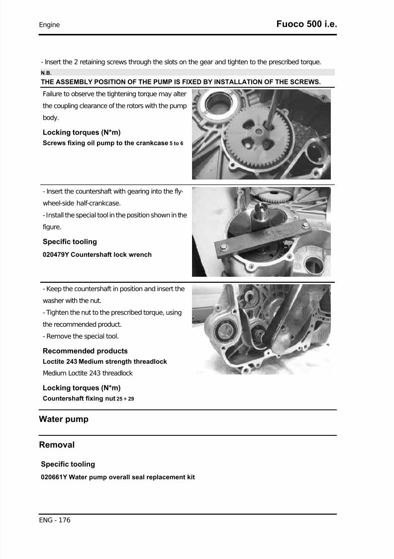
7/29/2019 Gilera Fuoco 500 i.e. (EN)
http://slidepdf.com/reader/full/gilera-fuoco-500-ie-en 176/329
- Insert the 2 retaining screws through the slots on the gear and tighten to the prescribed torque.
N.B.
THE ASSEMBLY POSITION OF THE PUMP IS FIXED BY INSTALLATION OF THE SCREWS.
Failure to observe the tightening torque may alter
the coupling clearance of the rotors with the pump
body.
Locking torques (N*m)
Screws fixing oil pump to the crankcase 5 to 6
- Insert the countershaft with gearing into the fly-
wheel-side half-crankcase.
- Install the special tool in the position shown in the
figure.
Specific tooling
020479Y Countershaft lock wrench
- Keep the countershaft in position and insert the
washer with the nut.
- Tighten the nut to the prescribed torque, using
the recommended product.
- Remove the special tool.
Recommended products
Loctite 243 Medium strength threadlock
Medium Loctite 243 threadlock
Locking torques (N*m)
Countershaft fixing nut 25 ÷ 29
Water pump
Removal
Specific tooling
020661Y Water pump overall seal replacement kit
Engine Fuoco 500 i.e.
ENG - 176

7/29/2019 Gilera Fuoco 500 i.e. (EN)
http://slidepdf.com/reader/full/gilera-fuoco-500-ie-en 177/329
- Remove the six screws and the pump cover with
a screwdriver.
- Unscrew the water pump rotor with an 8-mm
wrench.
- Place two flat blade screwdrivers as shown in the
figure so as to lever on the marked crankcase
edge and disassemble the overall seal, pressure-
fitted on the rotor shaft.CAUTION
USE TEFLON AS SHOWN IN THE FIGURE SO AS NOT TODAMAGE THE WATER PUMP COVER SEALING SUR-FACE. SMALL SCRATCHES ON THE SEAT EDGE DO NOTPOSE FUNCTIONAL PROBLEMS.
- Change the position of the screwdrivers if nec-
essary.
- During seal disassembly, the ceramic may split.
Fuoco 500 i.e. Engine
ENG - 177

7/29/2019 Gilera Fuoco 500 i.e. (EN)
http://slidepdf.com/reader/full/gilera-fuoco-500-ie-en 178/329
- Clean all the parts thoroughly before removing
them.
- Place the extractor together with the pin on the
fixed part of the ceramic seal.
- Without modifying the extractor position, make
three holes on the fixed part of the seal using thepin supplied and a hammer.
N.B.
MAKE THE HOLES WITH A STRONG HIT.MULTIPLE LIGHT BLOWS COULD DEFORM THE PARTWITHOUT PASSING THROUGH.
- Fix the extractor to the fixed part of the sealing
using the screws supplied with the tool.
CAUTION
FIX IT PROPERLY WITHOUT "TEARING" THE PLATE
- Complete the tool by fitting the bracket, the screw
and the nut.
Engine Fuoco 500 i.e.
ENG - 178

7/29/2019 Gilera Fuoco 500 i.e. (EN)
http://slidepdf.com/reader/full/gilera-fuoco-500-ie-en 179/329
- Hold the screw in position and operate the nut
until the fixed part of the sealing is completely re-
moved.
- Remove the extractor with the fixed part of the
overall seal.
Fitting
OVERALL SEAL FITTING
CAUTIONCLEAN ALL THE COMPONENTS THOROUGHLY.
CAUTION
LUBRICATE THE ROTOR SHAFT WITH ENGINE OIL.
- Fit the tie rod by screwing it to the rotor shaft.
CAUTIONTIGHTEN MANUALLY UNTIL IT STOPS.
- Place the overall seal on the shaft.
Fuoco 500 i.e. Engine
ENG - 179

7/29/2019 Gilera Fuoco 500 i.e. (EN)
http://slidepdf.com/reader/full/gilera-fuoco-500-ie-en 180/329
- Place the calibrated punch (at preloading value).
- Fit the nut to the tie rod.
- Keep the tie rod in position and screw the nut up
to the end of stroke.
- The tool will drive the fixed part seat on the crank-
case and the movable part seat on the shaft, thus
obtaining the correct ceramic seal preloading.
- Screw the rotor.
Locking torques (N*m)
Water pump impeller 4 ÷ 5
- Fit the pump cover with a new gasket, lubricate
the gasket previously with petroleum jelly grease.
- Tighten the six cover screws to the prescribed
torque.N.B.
TO AVOID DEFORMATION, DO NOT LUBRICATE THE O-RING WITH PETROLEUM GREASE.
Locking torques (N*m)
Water pump cover screws 3 ÷ 4
Engine Fuoco 500 i.e.
ENG - 180
7/29/2019 Gilera Fuoco 500 i.e. (EN)
http://slidepdf.com/reader/full/gilera-fuoco-500-ie-en 181/329
INDEX OF TOPICS
INJECTION INJEC

7/29/2019 Gilera Fuoco 500 i.e. (EN)
http://slidepdf.com/reader/full/gilera-fuoco-500-ie-en 182/329
KEY:
1. Throttle body and injection electronic control unit (MIU)
2. Battery
3. Instrument panel
4. Injection load remote control
5. Coolant temperature sensor
6. HV coil
7. Fuel pump
8. Lambda probe9. Revolution sensor
10. Fuel injector
11. Diagnosis connector
MIU injection system
This vehicle is fitted with an integrated injection and ignition system.
Injection is indirect in the manifold through an electro-injector.
The injection and ignition are timed on the four-stroke cycle by means of a tone wheel keyed on to the
crankshaft (24-2 teeth) and pick-up sensor.
Injection Fuoco 500 i.e.
INJ EC - 182

7/29/2019 Gilera Fuoco 500 i.e. (EN)
http://slidepdf.com/reader/full/gilera-fuoco-500-ie-en 183/329
Combustion and ignition are managed on the basis of engine revs and throttle valve opening. Further
corrections are made according to the following parameters:
- Coolant temperature.
- Intake air temperature
- Lambda probe
The system implements an idle feeding correction with cold engine through a Stepper motor on a by-
pass circuit of the throttle valve. The control unit manages the Stepper motor and the injector opening
time, thereby ensuring the idle steadiness and the proper combustion.
In all conditions of use, mixture preparation is managed by modifying the injector opening time.
The fuel system pressure is kept constant based on the ambient pressure.
The fuel system circuit consists of:
- Fuel pump- Fuel filter
- Injector
- Pressure regulator
The pump, the filter and the regulator are placed inside the fuel tank on a single support.
The injector is connected by a pipe with fast-release fittings. The pressure regulator is located at the
beginning of the circuit.
The fuel pump is controlled by the MIU; this ensures safety of the vehicle.
The ignition circuit consists of:- HV coil
- HV cable
- Shielded cap
- MIU control unit
- Spark plug
The MIU control unit manages ignition with the best advance ensuring four-stroke timing (ignition only
in the compression phase) at the same time.
The MIU injection-ignition system controls engine functions by means of a pre-set program.
Should any input signals fail, an acceptable working order of the engine is ensured to allow the user to
reach a service station.
Of course, this cannot happen when the rpm-timing signal is missing, or when the failure involves the
control circuits:
- Fuel pump
- HV coil
- Injector
Fuoco 500 i.e. Injection
INJ EC - 183

7/29/2019 Gilera Fuoco 500 i.e. (EN)
http://slidepdf.com/reader/full/gilera-fuoco-500-ie-en 184/329
The control unit is provided with a self-diagnosis
system connected to an indicator light in the in-
strument panel.
Failures are detected and restored by the diag-
nostic tester.
In any case, when the fault is no longer present,
the data storage is automatically cleared after 16cycles of use (cold start, running at regular engine
temperature, stop).
The diagnostic tester is also required to adjust the
idle mixture.
Specific tooling
020680Y Diagnosis Tool
The MIU injection-ignition system carries out
checks on the rpm indicator and the electric fan for
radiator cooling.
The MIU control unit has a decoder for the anti-
theft immobilizer system.
The MIU control unit is connected to a diagnostic
LED on the instrument panel, that also carries out
the deterrent flashing functions.
The MIU control unit power supply is furthermore controlled by the emergency switch; that is to provide
further safety for the vehicle.
Precautions
1. Before fixing any part of the injection system, check to see if there are any registered faults. Do not
disconnect the battery before checking for faults.
2. The fuel supply system is pressurised at 300 kPa (3 BAR). Before disconnecting the fast-release
fitting of the fuel supply pipe, check that there are no naked flames. Do not smoke. Act with caution to
avoid spraying fuel to your eyes.
3. When fixing electric components, operate with the battery connected only when actually required.
4. When functional checks are performed, check that the battery voltage is over 12V.
Injection Fuoco 500 i.e.
INJ EC - 184

7/29/2019 Gilera Fuoco 500 i.e. (EN)
http://slidepdf.com/reader/full/gilera-fuoco-500-ie-en 185/329
5. Before any attempt to start the vehicle, check to make sure there is at least two litres of fuel in the
tank. Failure to respect this norm will damage the fuel pump.
6. If the scooter is expected to remain unused for a long time, refill the tank up to a little over half the
level. This will ensure the pump will be covered by fuel.
7. When washing the vehicle, be careful with the electric components and cable harnesses.
8. When an ignition problem is detected, start the checks from the battery and the injection system
connections.
9. Before disconnecting the MIU ECU connector, perform the following steps in the order shown:
- Set the switch to «OFF»
- Disconnect the battery
Failure to respect this norm may damage the control unit.
10. Do not invert the poles when fitting the battery.11. To avoid causing any damage, disconnect and reconnect the MIU system connectors only if re-
quired. Before reconnecting, check that the connectors are dry.
12. When carrying out electric inspections, do not force the tester probes into the connectors. Do not
take measurements not specifically foreseen by the manual.
13. At the end of every check performed with the diagnostic tester, remember to protect the system
connector with its cap. Failure to observe this precaution may damage the MIU control unit.
14. Before reconnecting the quick couplers of the power supply system, check that the terminals are
perfectly clean.
Troubleshooting hints
1 A MIU failure is more likely to be due to the connections than to the components.
Before troubleshooting the MIU system, carry out the following checks:
A: Electrical power supply
a. Battery voltage
b. Blown fuse
c. Remote controls
d. Connectors
B: Chassis ground
C: Fuel system
a. Broken fuel pump
b. Dirty fuel filter
D: Ignition system
a. Faulty spark plug
b. Broken coil
c. Broken shielded cap
E: Intake circuit
a. Dirty air filter
Fuoco 500 i.e. Injection
INJ EC - 185
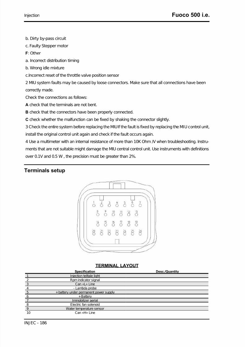
7/29/2019 Gilera Fuoco 500 i.e. (EN)
http://slidepdf.com/reader/full/gilera-fuoco-500-ie-en 186/329
b. Dirty by-pass circuit
c. Faulty Stepper motor
F: Other
a. Incorrect distribution timing
b. Wrong idle mixture
c.Incorrect reset of the throttle valve position sensor
2 MIU system faults may be caused by loose connectors. Make sure that all connections have been
correctly made.
Check the connections as follows:
A check that the terminals are not bent.
B check that the connectors have been properly connected.
C check whether the malfunction can be fixed by shaking the connector slightly.3 Check the entire system before replacing the MIUIf the fault is fixed by replacing the MIU control unit,
install the original control unit again and check if the fault occurs again.
4 Use a multimeter with an internal resistance of more than 10K Ohm /V when troubleshooting. Instru-
ments that are not suitable might damage the MIU central control unit. Use instruments with definitions
over 0.1V and 0.5 W , the precision must be greater than 2%.
Terminals setup
TERMINAL LAYOUTSpecification Desc./Quantity
1 Injection telltale light2 Rpm indicator signal3 Can «L» Line4 - Lambda probe5 +battery under permanent power supply6 +Battery7 Immobilizer aerial
8 Electric fan solenoid9 Water temperature sensor10 Can «H» Line
Injection Fuoco 500 i.e.
INJ EC - 186

7/29/2019 Gilera Fuoco 500 i.e. (EN)
http://slidepdf.com/reader/full/gilera-fuoco-500-ie-en 187/329
Specification Desc./Quantity
11 +Lambda probe12 engine stop switch13 Engine speed sensor (+)14 Fuel injector15 Engine speed sensor (-)
16 Diagnostics socket output17 Immobilizer LED18 Ground lead Connected to the engine stop switch and the water tem-
perature sensor.19 -20 Injection load solenoid21 -22 HV coil23 -24 Start up enabling25 -26 Ground lead
EMS circuit diagram
SYSTEM SCHEMATIC
Specification Desc./Quantity
1 Battery 12V - 12 Ah2 Speed sensor3 Water temperature sensor4 Immobilizer aerial5 Stop button6 Fuse 20 A7 Fuse 7.5 A8 Ignition key contacts9 engine stop switch10 Fuse 7.5 A
11 Fuse 15A12 Fuse 10 A13 Starter button
Fuoco 500 i.e. Injection
INJ EC - 187

7/29/2019 Gilera Fuoco 500 i.e. (EN)
http://slidepdf.com/reader/full/gilera-fuoco-500-ie-en 188/329
Specification Desc./Quantity
14 Injection load solenoid15 Start-up remote control relay16 Electric fan solenoid17 Starter motor18 Electric fan
19 Fuel pump20 HV coil21 Fuel injector22 Lambda probe23 Rpm indicator24 "WARNING" light25 Immobilizer LED26 Diagnostics socket connector27 Start-up solenoid28 Control unit power device
Troubleshooting procedure
Engine does not start
ENGINE DOES NOT START IF ONLY PULLEDPossible Cause Operation
Immobiliser enabling signal System not encodedSystem not efficient, repair according to the indications of the
self-diagnosisPresence of faults detected by the self diagnosis Pump relay
HV coilInjector
Revolution timing sensorFuel system Fuel in the tank
Fuel pump activationFuel pressure (low)
Injector capacity (low)Power to the spark plug Shielded spark plug cap HV coil (secondary insulation)
Parameter reliability Coolant temperatureDistribution timing - injection ignition
Intake air temperatureEnd of compression pressure End of compression pressure
Starting difficulties
ENGINE START-UP PROBLEMS
Possible Cause OperationPresence of faults detected by the self diagnosis Pump relay
HV coilInjector
Revolution timing sensorAir temperature
Coolant temperatureStart-up speed Starter motor and solenoid
BatteryGround connections
End of compression pressure End of compression pressurePower to the spark plug Spark plug
Shielded capHV coil
Speed-timing sensor
Ignition advanceFuel system Fuel pressure (low)
Injector capacity (low)
Injection Fuoco 500 i.e.
INJ EC - 188

7/29/2019 Gilera Fuoco 500 i.e. (EN)
http://slidepdf.com/reader/full/gilera-fuoco-500-ie-en 189/329
Possible Cause Operation
Injector sealing (poor)Correctness of the parameters Coolant temperature
Stepper throttle valve position intake air temperature (stepsand actual opening)
Cleaning of the auxiliary air pipe and throttle valve; air filter ef-
ficiency
Engine stops at idle
ENGINE DOES NOT IDLE/ IDLING IS UNSTABLE/ IDLING TOO LOWPossible Cause Operation
Presence of faults detected by the self diagnosis Pump relayHV coilInjector
Revolution timing sensorAir temperature
Coolant temperature
Ignition efficiency Spark plugIgnition timing
Correctness of the parameters Throttle valve position sensorStepper
Coolant temperature sensorIntake air temperature sensor
Intake system cleaning Air filterDiffuser and throttle valve
Additional air pipe and StepperIntake system sealing (infiltrations) Intake manifold - head
Throttle body - manifoldIntake sleeve
Filter boxFuel system (low pressure) Fuel pump
Pressure regulator
Fuel filterInjector capacity
Engine does not rev down
ENGINE DOES NOT RETURN TO IDLING SPEED/IDLING SPEED TOO HIGH
Possible Cause Operation
Presence of faults detected by the self diagnosis Pump relayHV coilInjector
Revolution timing sensorAir temperature
Coolant temperatureIgnition efficiency Ignition timingCorrectness of the parameters Throttle valve position sensor
StepperCoolant temperature sensor
Intake air temperature sensorIntake system sealing (infiltrations) Intake manifold - head
Throttle body - manifoldIntake sleeve
Filter boxFuel system (low pressure) Fuel pump
Pressure regulatorFuel filter
Injector capacity
Fuoco 500 i.e. Injection
INJ EC - 189

7/29/2019 Gilera Fuoco 500 i.e. (EN)
http://slidepdf.com/reader/full/gilera-fuoco-500-ie-en 190/329
Exhaust backfires in deceleration
EXHAUST BACKFIRES WHEN DECELERATINGPossible Cause Operation
Presence of faults detected by the self diagnosis Pump relayHV coilInjector
Revolution timing sensorAir temperature
Coolant temperatureLambda probe
Correctness of the parameters Throttle valve position sensorStepper
Coolant temperature sensorIntake air temperature sensor
Intake system sealing (infiltrations) Intake manifold - head Throttle body - manifold
Intake sleeveFilter box
Fuel system (low pressure) Fuel pumpPressure regulator
Fuel filterInjector capacity
Exhaust system sealing (infiltrations) Manifold - headManifold - silencersilencer welding
Engine revs irregularly
ENGINE IRREGULAR PERFORMANCE WITH VALVE SLIGHTLY OPEN
Possible Cause Operation
Intake system cleaning Air filterDiffuser and throttle valve
Additional air pipe and StepperIntake system sealing Intake sleeve
Filter boxIgnition system Spark plug wear check
Parameter reliability Throttle valve position signalCoolant temperature indicator
Intake air temperature indicatorIgnition advance
TPS reset successful TPS reset successfulPresence of faults detected by the self diagnosis Pump relay
HV coilInjector
Revolution timing sensor
Air temperatureCoolant temperatureLambda probe
Poor performance at full throttle
POOR ENGINE PERFORMANCE AT FULL POWER/ ENGINE IRREGULAR PERFORM-ANCE ON PICKUP
Possible Cause Operation
Presence of faults detected by the self diagnosis Pump relayHV coilInjector
Revolution timing sensorAir temperature
Coolant temperature
Injection Fuoco 500 i.e.
INJ EC - 190

7/29/2019 Gilera Fuoco 500 i.e. (EN)
http://slidepdf.com/reader/full/gilera-fuoco-500-ie-en 191/329
Possible Cause Operation
Lambda probeSpark plug power supply Spark plug
Shielded capHV cableHV coil
Intake system Air filterFilter box (sealing)
Intake sleeve (sealing)Parameter reliability Throttle valve position signal
Coolant temperature indicatorIntake air temperature indicator
Ignition advanceFuel system Fuel level in the tank
Fuel pressureFuel filter
Injector capacity
Engine knocking
PRESENCE OF KNOCKING (COMBUSTION SHOCKS)Possible Cause Operation
Presence of faults detected by the self diagnosis Pump relayHV coilInjector
Revolution timing sensorAir temperature
Coolant temperatureLambda probe
Ignition efficiency Spark plugParameter reliability Throttle valve position signal
Coolant temperature indicatorIntake air temperature indicator
Ignition advanceIntake system sealing Intake sleeveFilter box
TPS reset successful TPS reset successfulFuel system Fuel pressure
Fuel filterInjector capacity
Fuel qualitySelection of the cylinder base gasket thickness Selection of the cylinder base gasket thickness
Fuel supply system
The fuel supply circuit includes the electric pump, the filter, the pressure regulator, the electro-injector
and the fuel delivery pipes.
The electrical pump is located in the tank from which the fuel is pumped and sent to the injector through
the filter.
The pressure is controlled by the pressure regulator situated in the pump assembly in the tank.
Fuoco 500 i.e. Injection
INJ EC - 191

7/29/2019 Gilera Fuoco 500 i.e. (EN)
http://slidepdf.com/reader/full/gilera-fuoco-500-ie-en 192/329
Removing the butterfly valve
Remove the fuel piping clamping screw indicated
in the figure.
Remove the fast-release fitting from the injector
support
Injection Fuoco 500 i.e.
INJ EC - 192

7/29/2019 Gilera Fuoco 500 i.e. (EN)
http://slidepdf.com/reader/full/gilera-fuoco-500-ie-en 193/329
Remove the injector connector.
Remove the three screws fixing the manifold to the
cylinder head and the clip fixing the throttle body
to the manifold.
Remove the MIU ECU connector.
Fuoco 500 i.e. Injection
INJ EC - 193
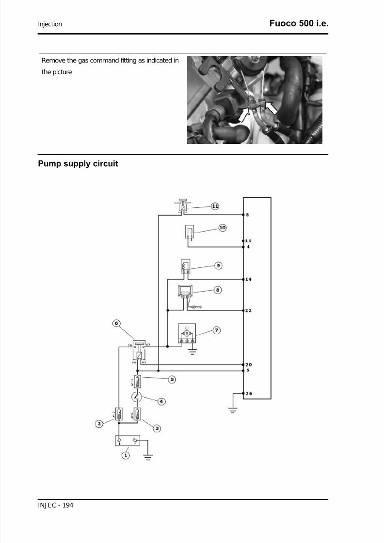
7/29/2019 Gilera Fuoco 500 i.e. (EN)
http://slidepdf.com/reader/full/gilera-fuoco-500-ie-en 194/329
Remove the gas command fitting as indicated in
the picture
Pump supply circuit
Injection Fuoco 500 i.e.
INJ EC - 194

7/29/2019 Gilera Fuoco 500 i.e. (EN)
http://slidepdf.com/reader/full/gilera-fuoco-500-ie-en 195/329
INJECTION LOADSSpecification Desc./Quantity
1 Battery 12V - 12 Ah2 Fuse 15A
3 Fuse 20A4 Ignition key contacts5 Fuse 7.5 A6 Injection load solenoid7 Fuel pump8 HV coil9 Fuel injector10 Lambda probe11 Electric fan solenoid
When switched to «ON», the fuel pump starts to rotate for 2 seconds and then stops. When the engine
starts up, in the presence of rpm timing signal the pump is continuously supplied.
ELECTRICAL DATA
• Pump winding resistance ~1.8 Ohm
• Input current during regular functioning 2.8 A
Check that the injection load 15A fuse No. 2 works
properly.
Check that the live control unit power supply 7.5A
fuse No. 10 works properly.
Check the efficiency of the injection load solenoid.
Check the resistance of the energising coil be-
tween pins 86 and 85: 40 to 80 Ohm
Apply a voltage of 12V to pins 86 and 85; make
sure that there is continuity between pins 30 and
87 of the solenoid.
Fuoco 500 i.e. Injection
INJ EC - 195

7/29/2019 Gilera Fuoco 500 i.e. (EN)
http://slidepdf.com/reader/full/gilera-fuoco-500-ie-en 196/329
Check the power supply line of the injection load
remote control energising coil: after switching to
«ON», make sure there is battery voltage, for 2
seconds, between the Red-White cable and theBlack-Purple cable of the remote control base. If
there is not, check the continuity of the Red-White
cable between the fuse box and the remote control
base and of the Black-Purple cable between the
pin 20 of the control unit and the remote control
base.
N.B.
CONTINUITY TESTS MUST BE CARRIED OUT WITH THECOMPONENTS DISCONNECTED. (SOLENOIDS, CON-
TROL UNIT, FUSES ETC.).
Injection Fuoco 500 i.e.
INJ EC - 196

7/29/2019 Gilera Fuoco 500 i.e. (EN)
http://slidepdf.com/reader/full/gilera-fuoco-500-ie-en 197/329
Check the presence of fixed voltage between the
grey/black cable of the remote control base and
earth. If there is none check the continuity of the
grey/black cable between the fuse box (No. 2 15A) and the remote control base.
N.B.
CONTINUITY TESTS MUST BE CARRIED OUT WITH THECOMPONENTS DISCONNECTED. (SOLENOIDS, CON-TROL UNIT, FUSES ETC.).
Fuoco 500 i.e. Injection
INJ EC - 197

7/29/2019 Gilera Fuoco 500 i.e. (EN)
http://slidepdf.com/reader/full/gilera-fuoco-500-ie-en 198/329
After switching to «ON», check that there is battery
voltage, for about 2 seconds, between the Black-
Green cable of the pump connector and the
ground lead with the pump connector disconnec-
ted. Otherwise, check the continuity of the Black-
Green cable between the pump connector and the
remote control base.
Check the efficiency of the earth line of the fuel
pump by measuring the continuity between the
pump connector black cable, system side, and the
earth.
If, when switching to «ON», the pump continues toturn after 2 seconds of activation, check, with the
control unit disconnected and the injection load re-
mote control disconnected, that the Black-Purple
cable (pin 20 on the interface wiring) is insulated
from the ground.
Specific tooling
020331Y Digital multimeter
Circuit leak test
Install the specific tool for checking the fuel pressure, with the pipe fitted with the gauge.
Check during regular operation by placing the ap-
propriate tool between the pump and the injector.
With battery voltage >12 V check that the fuel
pressure is 3 BAR and that the input current is ~2.8
A
With the battery voltage >12 V, check the pump flow rate by disconnecting from the injector the pipe
equipped with the pressure gauge of the appropriate tool. Get a graded burette with a flow rate of
approximately 1 L. Rotate the pump using the active diagnoses of the palm top computer. Using a pair
of long flat needle-nose pliers, choke the fuel pipe making the pressure stabilise at approx. 2.9 ÷3 BAR.
Pay attention not to choke the pipe too much, as the pressure remains equal to 3 BAR while the flow
diminishes. Check that within 15 seconds the pump has a flow rate of approx. 300 cm³.
Specific tooling
Injection Fuoco 500 i.e.
INJ EC - 198

7/29/2019 Gilera Fuoco 500 i.e. (EN)
http://slidepdf.com/reader/full/gilera-fuoco-500-ie-en 199/329
020480Y Petrol pressure check kit
Fuel filter check
Disconnect the terminals from the electric pump
Remove the screw shown in the picture
Remove the clip fixing the piping to the filter shown
in the picture
Separate the lower part of the pump mounting as
shown in the picture.
Fuoco 500 i.e. Injection
INJ EC - 199
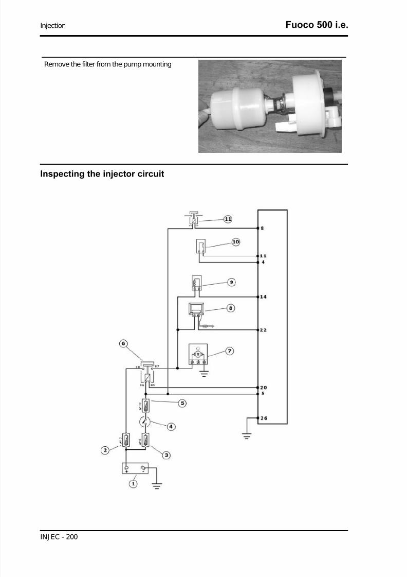
7/29/2019 Gilera Fuoco 500 i.e. (EN)
http://slidepdf.com/reader/full/gilera-fuoco-500-ie-en 200/329
Remove the filter from the pump mounting
Inspecting the injector circuit
Injection Fuoco 500 i.e.
INJ EC - 200
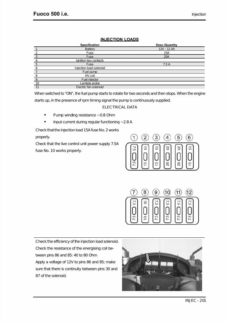
7/29/2019 Gilera Fuoco 500 i.e. (EN)
http://slidepdf.com/reader/full/gilera-fuoco-500-ie-en 201/329
INJECTION LOADSSpecification Desc./Quantity
1 Battery 12V - 12 Ah2 Fuse 15A
3 Fuse 20A4 Ignition key contacts5 Fuse 7.5 A6 Injection load solenoid7 Fuel pump8 HV coil9 Fuel injector10 Lambda probe11 Electric fan solenoid
When switched to "ON", the fuel pump starts to rotate for two seconds and then stops. When the engine
starts up, in the presence of rpm timing signal the pump is continuously supplied.
ELECTRICAL DATA
• Pump winding resistance ~0.8 Ohm
• Input current during regular functioning ~2.8 A
Check that the injection load 15A fuse No. 2 works
properly.
Check that the live control unit power supply 7.5A
fuse No. 10 works properly.
Check the efficiency of the injection load solenoid.
Check the resistance of the energising coil be-
tween pins 86 and 85: 40 to 80 Ohm
Apply a voltage of 12V to pins 86 and 85; make
sure that there is continuity between pins 30 and
87 of the solenoid.
Fuoco 500 i.e. Injection
INJ EC - 201

7/29/2019 Gilera Fuoco 500 i.e. (EN)
http://slidepdf.com/reader/full/gilera-fuoco-500-ie-en 202/329
Check the power supply line of the injection load
remote control energising coil: after switching to
"ON", make sure there is battery voltage, for two
seconds, between the Red-White cable and Black-Purple cable of the remote control base. If there is
not, check the continuity of the Red-White cable
between the fuse box and the remote control base
and of the Black-Purple cable between the pin 20
of the control unit and the remote control base.
N.B.
CONTINUITY TESTS MUST BE CARRIED OUT WITH THECOMPONENTS DISCONNECTED. (SOLENOIDS, CON-TROL UNIT, FUSES ETC.).
Injection Fuoco 500 i.e.
INJ EC - 202

7/29/2019 Gilera Fuoco 500 i.e. (EN)
http://slidepdf.com/reader/full/gilera-fuoco-500-ie-en 203/329
Check the presence of fixed voltage between the
grey/black cable of the remote control base and
earth. If there is none check the continuity of the
grey/black cable between the fuse box (No. 2 15A) and the remote control base.
N.B.
CONTINUITY TESTS MUST BE CARRIED OUT WITH THECOMPONENTS DISCONNECTED. (SOLENOIDS, CON-TROL UNIT, FUSES ETC.).
Fuoco 500 i.e. Injection
INJ EC - 203

7/29/2019 Gilera Fuoco 500 i.e. (EN)
http://slidepdf.com/reader/full/gilera-fuoco-500-ie-en 204/329
With the control unit and the injector disconnected,
check the continuity of the Red-Yellow cable be-
tween pin 14 of the interface wiring and the injector
connector
Switch to «ON» and check if there is voltage, with
injector disconnected and control unit connected,
between the Black-Green cable of the injector con-
nector and the ground lead
With injector disconnected and the injector load
solenoid disconnected, check the continuity of the
Black-Green cable between the injector connector
and solenoid base.
Inspecting the injector hydraulics
To check the injector, remove the inlet manifold by
removing the three fixing screws at the head and
the three screws connecting the control unit to the
manifold.
Injection Fuoco 500 i.e.
INJ EC - 204

7/29/2019 Gilera Fuoco 500 i.e. (EN)
http://slidepdf.com/reader/full/gilera-fuoco-500-ie-en 205/329
Install the appropriate tool for the fuel pressure
check and position the manifold over a container
graduated by at least 100 cc. Connect the injector
with the cable making up part of the supply for the
injection tester. Connect the clamps of the cable
to an auxiliary battery. Activate the fuel pump with
the active diagnosis. Check that within 15 approx.
70 cm³ of fuel is delivered with adjustment pres-
sure of approx. 3 BAR.
Specific tooling
020480Y Petrol pressure check kit
Proceed with the injector seal test.
Dry the injector outlet with a blast of compressed
air. Activate the fuel pump. Wait for one minute,
making sure there are no leaks coming from theinjector. Slight oozing is normal.
Value limit =1 drop per minute
Immobiliser circuit
After removing the leg shield back plate, remove
the electrical connection from the aerial as shown
in the picture.
Fuoco 500 i.e. Injection
INJ EC - 205
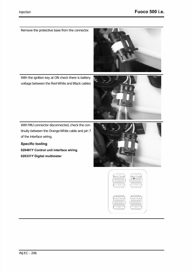
7/29/2019 Gilera Fuoco 500 i.e. (EN)
http://slidepdf.com/reader/full/gilera-fuoco-500-ie-en 206/329
Remove the protective base from the connector.
With the ignition key at ON check there is battery
voltage between the Red-White and Black cables
With MIU connector disconnected, check the con-
tinuity between the Orange-White cable and pin 7
of the interface wiring.
Specific tooling
020481Y Control unit interface wiring
020331Y Digital multimeter
Injection Fuoco 500 i.e.
INJ EC - 206

7/29/2019 Gilera Fuoco 500 i.e. (EN)
http://slidepdf.com/reader/full/gilera-fuoco-500-ie-en 207/329
The electronic ignition system is controlled by the
control unit with the integrated Immobilizer sys-
tem. The immobilizer is an anti-theft system that
allows the vehicle to be operated only when it is
started with coded keys recognised by the control
unit. The code is integrated in a transponder in the
key block. This allows the driver clear operation
without having to do anything other than just turn-
ing the key. The Immobilizer system consists of the
following components:
- an electronic control unit
- immobilizer aerial- Master key with incorporated transponder (red
key)
- service key with incorporated transponder (black
key)
- HV coil
- diagnosis LED
The diagnosis LED also works as a theft-deterrent
blinker. This function is activated every time the
ignition switch is turned to the "OFF" position, or
the emergency stop switch is turned to the "OFF"
position. It remains activated for 48 hours in order
not to affect the battery charge. When the ignition
switch is turned to the "ON" position, the theft-de-
terrent blinker function is deactivated. Subse-
quently, a flash confirms the switching to the "ON"
status. The duration of the flash depends on the
programming of the electronic control unit If the
LED is off regardless of the position of the ignition-
key switch and/or the instrument panel is not initi-
ated, check if:
• there is battery voltage
• fuses 1,7,10 are in working order
• there is power to the control unit as
specified below:
Fuoco 500 i.e. Injection
INJ EC - 207

7/29/2019 Gilera Fuoco 500 i.e. (EN)
http://slidepdf.com/reader/full/gilera-fuoco-500-ie-en 208/329
Remove the connector support bracket shown in
the photograph and disconnect the connector from
the control unit. Check the following conditions:
With the key switch set to OFF:
• if there is battery voltage between ter-
minals 6-26 and terminal 6-chassis
ground (fixed power supply). If there is
no voltage check that fuse 1 and its ca-
ble are in working order.
With the key switch in the OFF position:
• there is battery voltage between termi-
nals 5-26 and terminal 5-frame earth
(fixed power supply). If there is no volt-
age, check the key switch contacts,
that fuse no. 10 and its cable are in
working order.
•
There is continuity between terminals12-18 with the emergency cut-off
switch in the RUN position. If there is
no continuity check the contacts of the
switch.
If no faults are found, replace the electronic control
unit.
Virgin circuit
When the ignition system is not encrypted, any key will start the engine but limited to 2000 rpm. The
keys can only be recognised if the control unit has been programmed properly. The data storage pro-
cedure for a previously not programmed control unit provides for the recognition of the master as the
first key to be stored to memory: this becomes particularly important because it is the only key that
enables the control unit to be wiped clean and reprogrammed for the memorisation of the service keys.
The master and service keys must be used to code the system as follows:
- Insert the Master key, turn it to «ON» and keep this position for two seconds (limit values 1 to 3
seconds).
Injection Fuoco 500 i.e.
INJ EC - 208

7/29/2019 Gilera Fuoco 500 i.e. (EN)
http://slidepdf.com/reader/full/gilera-fuoco-500-ie-en 209/329
- Insert the service key and turn it to «ON» for 2 seconds.
- If you have copies of the key, repeat the operation with each key.
- Insert the MASTER key again and turn it to «ON» for 2 seconds.
The maximum time to change keys is 10 seconds.
A maximum of 7 service keys can be programmed at one time.
It is essential to adhere to the times and the procedure. If you do not, start again from the beginning.
Once the system has been programmed, the master key transponder is strictly matched with the control
unit. With this link established, it is now possible to encode new service keys, in the event of losses,
replacements, etc. Each new programming deletes the previous one; to add or delete a key it is therefore
necessary to repeat the procedure using all the keys that you intend to keep in use. If a service key
becomes uncoded, the efficiency of the high voltage circuit shielding must be thoroughly inspected: In
any case it is advisable to use resistive spark plugs.Characteristic
MASTER key:
RED KEY
SERVICE key.
BLACK KEY
Diagnostic codes
The Immobilizer system is tested each time the ig-
nition key is turned from «OFF» to «ON». During
this diagnosis phase a number of control unit sta-
tuses can be identified and various light codes
displayed. Regardless of the code transmitted, if
at the end of the diagnosis the LED remains off
permanently, the ignition is enabled. If, however,
the LED remains on permanently, it means the ig-
nition is inhibited:1. Previously unused control unit - key inser-
ted: a single 2 second flash is displayed, after
which the LED remains off permanently. The keys
can be stored to memory, the vehicle can be star-
ted but with a limitation imposed on the number of
revs.
2. Previously unused control unit - transpond-
er absent or cannot be used: the LED is on
Fuoco 500 i.e. Injection
INJ EC - 209

7/29/2019 Gilera Fuoco 500 i.e. (EN)
http://slidepdf.com/reader/full/gilera-fuoco-500-ie-en 210/329
permanently. In this condition no operations are
possible including the start up of the vehicle.
3. Programmed control unit - the service key in
(normal condition of use): a single 0.7-second
flash is displayed, after which the LED remains off
steadily. The engine can be started.
4. Programmed control unit - Master key in: a
0.7-sec flash is displayed followed by the LED re-
maining off for 2 sec and then by short 0.46-sec
flashes, the same number of times as there are
keys stored in the memory including the Master
key. When the diagnosis has been completed, theLED remains permanently OFF. The engine can
be started.
5. Programmed control unit - fault detected: a light code is displayed according to the fault detected,
after which the LED remains on steadily. The engine cannot be started. The codes that can be trans-
mitted are:
• 1-flash code
• 2-flash code
• 3-flash code
The LED indication is divided into 3 steps:
1st step: A flash: "ON" switching recognition
2nd step: Series of flashes: diagnosis code indication
3rd step: Solid light on or off:
- ON =start-up disabled
- OFF =start-up enabled
Code 1
A one-flash code indicates a system where the se-
rial line is not present or is not detected. Check the
Immobilizer aerial wiring and change it if necessa-
ry.
Injection Fuoco 500 i.e.
INJ EC - 210

7/29/2019 Gilera Fuoco 500 i.e. (EN)
http://slidepdf.com/reader/full/gilera-fuoco-500-ie-en 211/329
Code 2
A two-flash code shows a system where the con-
trol unit does not show the transponder signal. This
might depend on the inefficiency of the immobiliser
aerial or the transponder.
Turn the switch to ON using several keys: if the
code is repeated even with the Master key, check
the aerial wiring and change it if necessary. If this
is not the case, replace the defective key and/or
reprogram the control unit. Replace the control unit
if the problem continues.
Code 3
A three-flash code indicates a system where the
control unit does not recognise the key. Turn the
switch to ON using several keys: if the error code
is repeated even with the Master key, replace the
control unit. If this is not the case, reprogram the
decoder.
Fuoco 500 i.e. Injection
INJ EC - 211
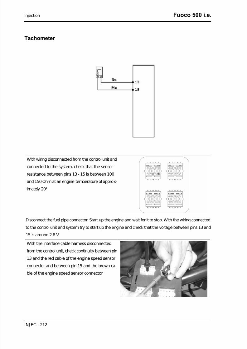
7/29/2019 Gilera Fuoco 500 i.e. (EN)
http://slidepdf.com/reader/full/gilera-fuoco-500-ie-en 212/329
Tachometer
With wiring disconnected from the control unit and
connected to the system, check that the sensor
resistance between pins 13 - 15 is between 100
and 150 Ohm at an engine temperature of approx-imately 20°
Disconnect the fuel pipe connector. Start up the engine and wait for it to stop. With the wiring connected
to the control unit and system try to start up the engine and check that the voltage between pins 13 and
15 is around 2.8 V
With the interface cable harness disconnectedfrom the control unit, check continuity between pin
13 and the red cable of the engine speed sensor
connector and between pin 15 and the brown ca-
ble of the engine speed sensor connector
Injection Fuoco 500 i.e.
INJ EC - 212

7/29/2019 Gilera Fuoco 500 i.e. (EN)
http://slidepdf.com/reader/full/gilera-fuoco-500-ie-en 213/329
With the interface cable harness disconnected
from the control unit and the rpm sensor connector
disconnected, check that the red and brown cables
(pin 13 - 15) are isolated from each other and in-
sulated from the ground lead.
Specific tooling
020481Y Control unit interface wiring
020331Y Digital multimeter
HT coil
Fuoco 500 i.e. Injection
INJ EC - 213
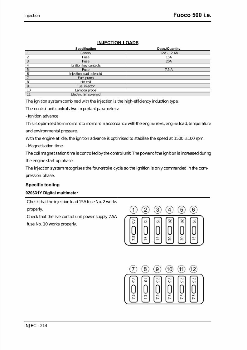
7/29/2019 Gilera Fuoco 500 i.e. (EN)
http://slidepdf.com/reader/full/gilera-fuoco-500-ie-en 214/329
INJECTION LOADSSpecification Desc./Quantity
1 Battery 12V - 12 Ah2 Fuse 15A
3 Fuse 20A4 Ignition key contacts5 Fuse 7.5 A6 Injection load solenoid7 Fuel pump8 HV coil9 Fuel injector10 Lambda probe11 Electric fan solenoid
The ignition system combined with the injection is the high-efficiency induction type.
The control unit controls two important parameters:
- Ignition advance
This is optimised from moment to moment in accordance with the engine revs, engine load, temperature
and environmental pressure.
With the engine at idle, the ignition advance is optimised to stabilise the speed at 1500 ±100 rpm.
- Magnetisation time
The coil magnetisation time is controlled by the control unit. The power of the ignition is increased during
the engine start-up phase.
The injection system recognises the four-stroke cycle so the ignition is only commanded in the com-
pression phase.
Specific tooling
020331Y Digital multimeter
Check that the injection load 15A fuse No. 2 works
properly.
Check that the live control unit power supply 7.5A
fuse No. 10 works properly.
Injection Fuoco 500 i.e.
INJ EC - 214

7/29/2019 Gilera Fuoco 500 i.e. (EN)
http://slidepdf.com/reader/full/gilera-fuoco-500-ie-en 215/329
Check the efficiency of the injection load solenoid.
Check the resistance of the energising coil be-
tween pins 86 and 85: 40 to 80 Ohm
Apply a voltage of 12V to pins 86 and 85; make
sure that there is continuity between pins 30 and
87 of the solenoid.
Check the power supply line of the injection load
remote control energising coil: after switching to
"ON", make sure there is battery voltage, for two
seconds, between the Red-White cable and Black-
Purple cable of the remote control base. If there is
not, check the continuity of the Red-White cable
between the fuse box and the remote control base
and of the Black-Purple cable between the pin 20
of the control unit and the remote control base.
N.B.
CONTINUITY TESTS MUST BE CARRIED OUT WITH THECOMPONENTS DISCONNECTED. (SOLENOIDS, CON-TROL UNIT, FUSES ETC.).
Fuoco 500 i.e. Injection
INJ EC - 215

7/29/2019 Gilera Fuoco 500 i.e. (EN)
http://slidepdf.com/reader/full/gilera-fuoco-500-ie-en 216/329
Check the presence of fixed voltage between the
grey/black cable of the remote control base and
earth. If there is none check the continuity of the
grey/black cable between the fuse box (No. 2 15A) and the remote control base.
N.B.
CONTINUITY TESTS MUST BE CARRIED OUT WITH THECOMPONENTS DISCONNECTED. (SOLENOIDS, CON-TROL UNIT, FUSES ETC.).
Injection Fuoco 500 i.e.
INJ EC - 216

7/29/2019 Gilera Fuoco 500 i.e. (EN)
http://slidepdf.com/reader/full/gilera-fuoco-500-ie-en 217/329
Check there is voltage between pins 22 and 26 of
the interface wiring for around two seconds when
switching to «ON».
Check the resistance of the primary coil between
pin 22 of the interface wiring and the green black
cable of the injection load remote control base with
the control unit disconnected and the remote con-
trol disconnected.
Primary resistance ~1 Ohm
Inspecting the spark plug shielded cap
Measure the shielded cap resistance.
Electric characteristic
Resistance:
5 K Ω
Fuoco 500 i.e. Injection
INJ EC - 217

7/29/2019 Gilera Fuoco 500 i.e. (EN)
http://slidepdf.com/reader/full/gilera-fuoco-500-ie-en 218/329
If different values are measured (<1; >20K Ω), replace the shielded cap.
N.B.
A SHIELDLESS CAP OR SPARK PLUG CAN ADVERSELY AFFECT THE INJECTION SYSTEM.FOR INFORMATION ON THE SPARK PLUG, SEE THE «SPECIFICATIONS» AND «MAINTE-
NANCE» CHAPTERS.
Spark advance
The ignition advance is determined electronically on the basis of parameters known by the control unit.
For this reason it is not possible to interpret the reference values based on the engine rpm.
The ignition advance value is detectable at any time using the diagnostic tester.
It is possible to check whether the ignition advance determined by the injection system matches the
value actually activated on the engine, by means of the stroboscopic light.
Specific tooling
020680Y Diagnosis Tool
020330Y Stroboscopic light to check timing
Proceed as follows:
- Remove the transmission compartment cover as
described in the "automatic transmission" chapter.
- Remove the TDC reference inspection cap be-
tween flywheel and crankcase cover. See the "fly-
wheel cover" chapter
Injection Fuoco 500 i.e.
INJ EC - 218

7/29/2019 Gilera Fuoco 500 i.e. (EN)
http://slidepdf.com/reader/full/gilera-fuoco-500-ie-en 219/329
- By the driving pulley, turn the engine to find the
alignment of the references to identify the TDC.
- Repeat for the reference between driving pulley
and engine crankcase.
- Refit the inspection cap on the flywheel side.
- Connect the diagnostic tester.
- Start the engine.
- Select the «parameters» function in this menu.- Select the stroboscopic light control in the tradi-
tional four-stroke engine position (1 spark, 2 revs).
- Check that the real values of rpm and ignition
advance match those measured using the diag-
nostic tester.
If the values do not match, check:
- distribution timing
- revolution timing sensor- injection control unit
Fuoco 500 i.e. Injection
INJ EC - 219

7/29/2019 Gilera Fuoco 500 i.e. (EN)
http://slidepdf.com/reader/full/gilera-fuoco-500-ie-en 220/329
Coolant temperature sensor
TEMPERATURE SENSORSpecification Desc./Quantity
1 Water temperature sensor2 engine stop switch3 Electronic control unit
With the control unit side connector disconnected
and the coolant temperature sensor connector
connected, check that the resistance values be-
tween pin 9 and ground correspond to the engine
temperature.
20° =2500 ±100Ω
80° =308 ±6Ω
With the control unit side connector disconnected
and the coolant temperature connector discon-
nected, check the insulation between the light
blue/green cable and ground.
Injection Fuoco 500 i.e.
INJ EC - 220

7/29/2019 Gilera Fuoco 500 i.e. (EN)
http://slidepdf.com/reader/full/gilera-fuoco-500-ie-en 221/329
With the control unit side connector disconnected
and the coolant temperature connector discon-
nected, check the continuity between pin 9 of the
interface wiring harness and the light blue/green
cable of the connector.
Specific tooling
020481Y Control unit interface wiring
020331Y Digital multimeter
Zeroing the throttle
Resetting the throttle valve position signal (TPS reset)
The MIU control unit is supplied with a throttle valve position sensor that is pre-calibrated.
Pre-calibration entails regulating the minimum opening of the throttle valve to obtain a certain flow of
air under pre-set reference conditions.
Pre-calibration ensures optimal air flow to control idling.
This regulation must not be tampered with in any way whatsoever.
The injection system will complete the management of the idling through the Stepper motor and the
variation of the ignition advance.
The throttle body after the pre-calibration has an opened valve with an angle that can vary depending
on the tolerances of the machining of the pipe and the valve itself. The valve position sensor can also assume various fitting positions. For these reasons the mV of the
sensor with the valve at idle can vary from one throttle body to another.
To obtain the optimum fuel mixture, especially at small openings of the throttle valve, it is essential to
match the throttle body with the control unit following the procedure known as TPS resetting.
With this operation we inform the control unit, as the starting point, of the mV value corresponding to
the pre-calibrated position.
To reset, proceed as follows.
Fuoco 500 i.e. Injection
INJ EC - 221
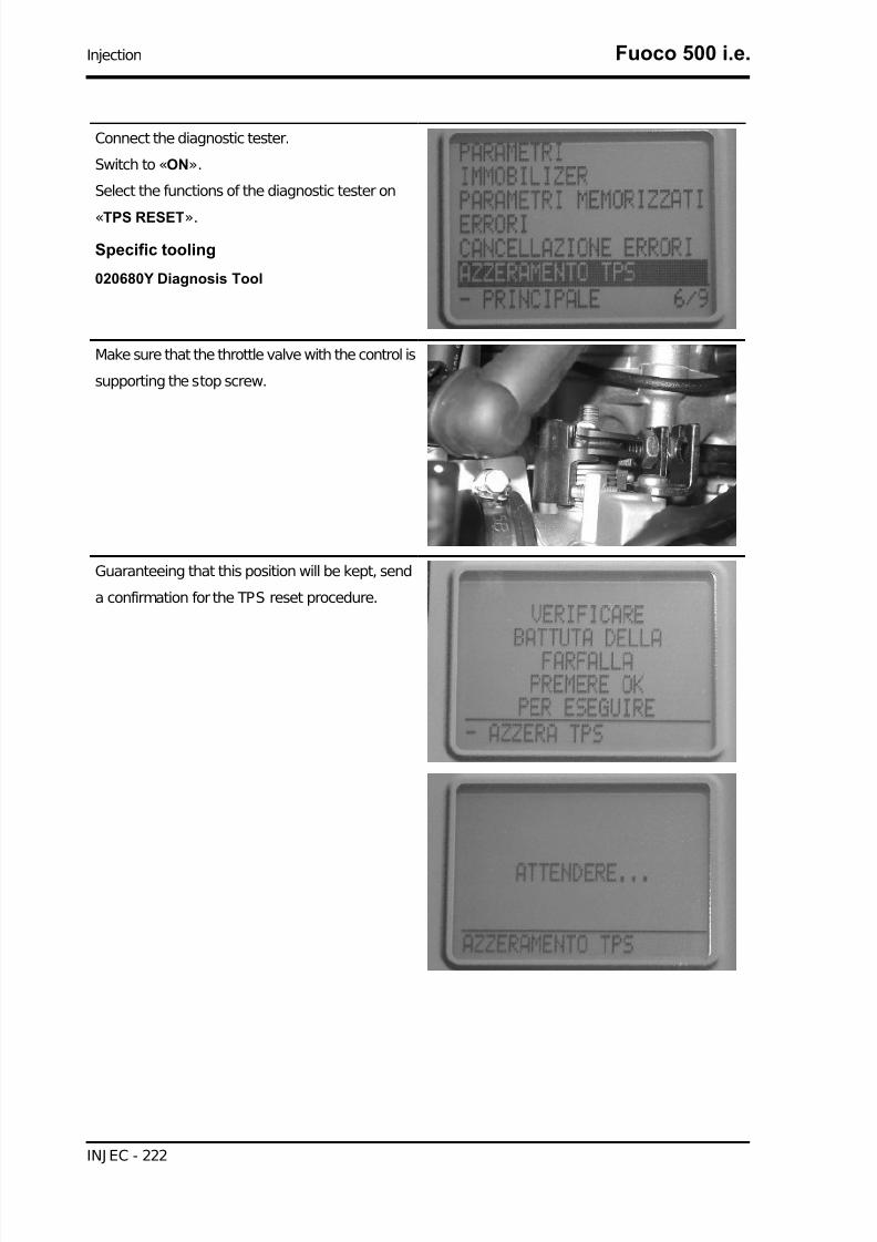
7/29/2019 Gilera Fuoco 500 i.e. (EN)
http://slidepdf.com/reader/full/gilera-fuoco-500-ie-en 222/329
Connect the diagnostic tester.
Switch to «ON».
Select the functions of the diagnostic tester on
«TPS RESET».
Specific tooling
020680Y Diagnosis Tool
Make sure that the throttle valve with the control is
supporting the stop screw.
Guaranteeing that this position will be kept, send
a confirmation for the TPS reset procedure.
Injection Fuoco 500 i.e.
INJ EC - 222
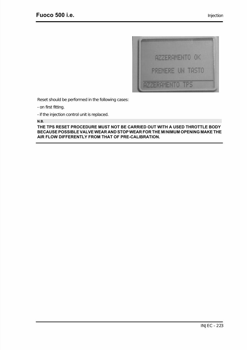
7/29/2019 Gilera Fuoco 500 i.e. (EN)
http://slidepdf.com/reader/full/gilera-fuoco-500-ie-en 223/329
Reset should be performed in the following cases:
- on first fitting.
- if the injection control unit is replaced.
N.B.THE TPS RESET PROCEDURE MUST NOT BE CARRIED OUT WITH A USED THROTTLE BODYBECAUSE POSSIBLE VALVE WEAR AND STOP WEAR FOR THE MINIMUM OPENING MAKE THEAIR FLOW DIFFERENTLY FROM THAT OF PRE-CALIBRATION.
Fuoco 500 i.e. Injection
INJ EC - 223

7/29/2019 Gilera Fuoco 500 i.e. (EN)
http://slidepdf.com/reader/full/gilera-fuoco-500-ie-en 224/329
Lambda probe
INJECTION LOADSSpecification Desc./Quantity
1 Battery 12V - 12 Ah2 Fuse 15A3 Fuse 20A4 Ignition key contacts5 Fuse 7.5 A6 Injection load solenoid7 Fuel pump8 HV coil9 Fuel injector10 Lambda probe
11 Electric fan solenoid
Injection Fuoco 500 i.e.
INJ EC - 224

7/29/2019 Gilera Fuoco 500 i.e. (EN)
http://slidepdf.com/reader/full/gilera-fuoco-500-ie-en 225/329
The Lambda sensor or oxygen sensor is a sensor which provides indications concerning the oxygen
content in the exhaust gas. The signal generated is not of the proportional type but of the ON/OFF type,
i.e. there is oxygen or there is not. The sensor is positioned on the exhaust manifold before the catalytic
converter in an area where the gas temperature is always high. The temperature at which the sensor
works is at least 350°C at 600°C and it has a reaction time of just 50 milliseconds. The signal generated
passes from a high value to a low value with a mixture with lambda =1.
Specific tooling
020481Y Control unit interface wiring
020331Y Digital multimeter
Check that the injection load 15A fuse No. 2 works
properly.
Check that the live control unit power supply 7.5A
fuse No. 10 works properly.
Check the efficiency of the injection load solenoid.
Check the resistance of the energising coil be-
tween pins 86 and 85: 40 to 80 Ohm
Apply a voltage of 12V to pins 86 and 85; make
sure that there is continuity between pins 30 and
87 of the solenoid.
Fuoco 500 i.e. Injection
INJ EC - 225

7/29/2019 Gilera Fuoco 500 i.e. (EN)
http://slidepdf.com/reader/full/gilera-fuoco-500-ie-en 226/329
Check the power supply line of the injection load
remote control energising coil: after switching to
"ON", make sure there is battery voltage, for two
seconds, between the Red-White cable and Black-Purple cable of the remote control base. If there is
not, check the continuity of the Red-White cable
between the fuse box and the remote control base
and of the Black-Purple cable between the pin 20
of the control unit and the remote control base.
N.B.
CONTINUITY TESTS MUST BE CARRIED OUT WITH THECOMPONENTS DISCONNECTED. (SOLENOIDS, CON-TROL UNIT, FUSES ETC.).
Injection Fuoco 500 i.e.
INJ EC - 226

7/29/2019 Gilera Fuoco 500 i.e. (EN)
http://slidepdf.com/reader/full/gilera-fuoco-500-ie-en 227/329
Install the electronic control unit interface wiring.
Start the engine and warm up until the electric fan
switches on.
Use an analogue multimeter with a direct voltagescale measuring down to 2 V.
Place the tips of the multimeter between pins 4 (-)
and 11 (+)
With the engine running at idle speed, check that
the voltage oscillates between 0V and 1V
With the throttle valve completely open, the volt-
age is approx. 1V.During the closing phase, the voltage is approx.
0V.
If the voltage remains constant, the sensor may be
damaged. Remove the sensor and check that
there are no oil or carbon deposits inside it..
Fuoco 500 i.e. Injection
INJ EC - 227

7/29/2019 Gilera Fuoco 500 i.e. (EN)
http://slidepdf.com/reader/full/gilera-fuoco-500-ie-en 228/329
INDEX OF TOPICS
SUSPENSIONS SUSP

7/29/2019 Gilera Fuoco 500 i.e. (EN)
http://slidepdf.com/reader/full/gilera-fuoco-500-ie-en 229/329
This section is dedicated to operations that can be carried out on the suspensions.
Front
Removing the front wheel
- Remove the 5 fixing screws indicated in the pic-
ture.
Locking torques (N*m)
Wheel fixing screw 20 to 25
Front wheel hub overhaul
- Remove the ball bearing check Seeger ring indi-
cated in the picture
Extract the ball bearing using the specific tool
Specific tooling
001467Y014 Calliper to extract ø 15-mm bear-
ings001467Y017 Bell for bearings, OD 39 mm
Fuoco 500 i.e. Suspensions
SUSP - 229

7/29/2019 Gilera Fuoco 500 i.e. (EN)
http://slidepdf.com/reader/full/gilera-fuoco-500-ie-en 230/329
- Remove the oil seal on the roller bearing side
using a screwdriver.
- Remove the roller bearing using the specific tool
Specific tooling
020376Y Adaptor handle
020456Y Ø 24 mm adaptor
020363Y 20-mm guide
- Heat the roller bearing seat with a heat gun
- Use the specific tool to introduce and push the
bearing until it stops, with the shielded side facing
out- Refit the ball bearing check Seeger ring
Specific tooling
020151Y Air heater
020376Y Adaptor handle
020359Y 42x47-mm Adaptor
020412Y 15-mm guide
- Use the specific tool to fit and push the roller cas-
ing until it stops
- Refit the oil seal on the roller bearing side
- Lubricate the area between the roller bearing and
the ball bearing
Specific tooling
020038Y Punch
Recommended products
AGIP GREASE MU3 Grease for odometer
transmission gear case
Suspensions Fuoco 500 i.e.
SUSP - 230

7/29/2019 Gilera Fuoco 500 i.e. (EN)
http://slidepdf.com/reader/full/gilera-fuoco-500-ie-en 231/329
Soap-based lithium grease with NLGI 3; ISO-L-
XBCHA3, DIN K3K-20
Handlebar
Removal
- Remove the three handlebar covers working as explained in the Bodywork Chapter.
- Remove the handlebar wiring retaining straps and disconnect the electric connectors from the brake
levers.
- Unscrew the fittings, then remove the front and rear brake pump piping.
- Remove the flexible transmission of the throttle grip and remove the throttle.
- Loosen the clamp fixing the handlebar to the steering tube and remove the handlebar by pulling it
upwards.
N.B.
IF THE HANDLEBAR IS BEING REMOVED TO REMOVE THE STEERING, IT IS ONLY NECESSARYTO TILT THE HANDLEBAR FORWARD ONTO THE FRONT PART OF THE VEHICLE WITHOUTREMOVING THE PARTS FITTED SO AS TO AVOID DAMAGING THE SHAFTS.
Refitting
Carry out the above operations by working in the reverse order from that used for removal.
Locking torques (N*m)
Handlebar fixing screw 50 ÷ 55
The tilt mechanism
Fuoco 500 i.e. Suspensions
SUSP - 231
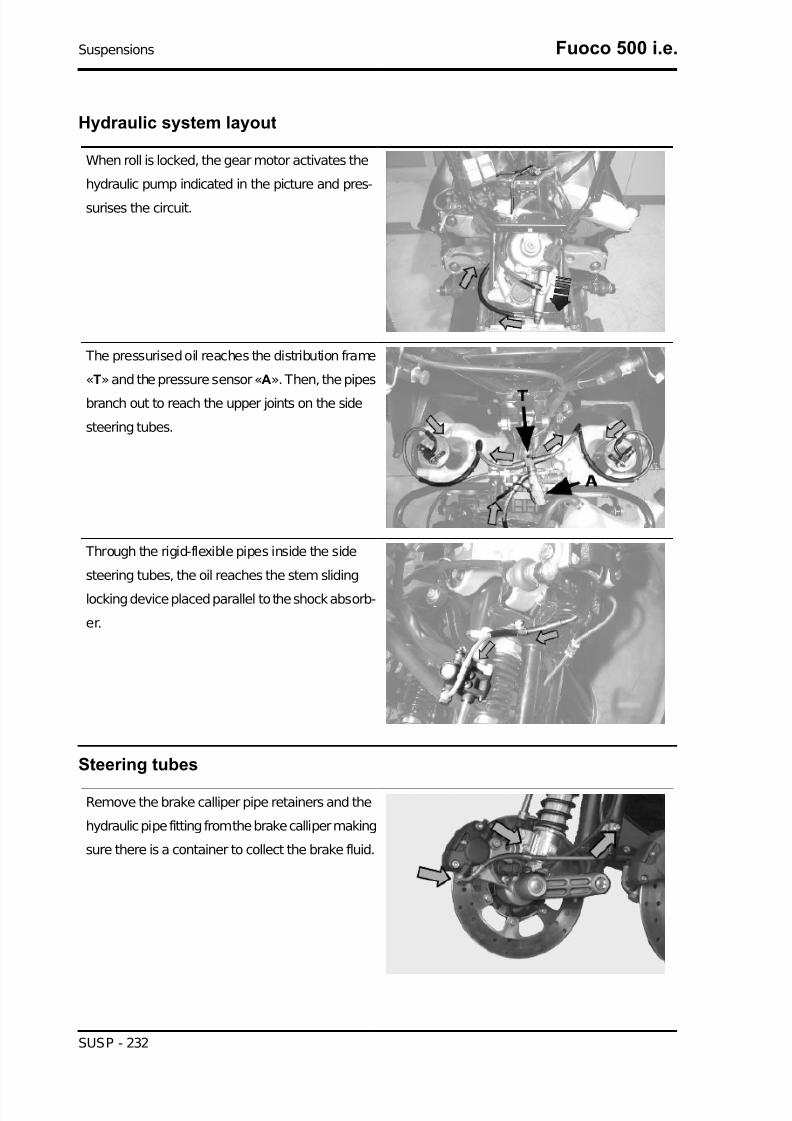
7/29/2019 Gilera Fuoco 500 i.e. (EN)
http://slidepdf.com/reader/full/gilera-fuoco-500-ie-en 232/329
Hydraulic system layout
When roll is locked, the gear motor activates the
hydraulic pump indicated in the picture and pres-
surises the circuit.
The pressurised oil reaches the distribution frame
«T» and the pressure sensor «A». Then, the pipes
branch out to reach the upper joints on the side
steering tubes.
Through the rigid-flexible pipes inside the side
steering tubes, the oil reaches the stem sliding
locking device placed parallel to the shock absorb-
er.
Steering tubes
Remove the brake calliper pipe retainers and the
hydraulic pipe fitting from the brake calliper making
sure there is a container to collect the brake fluid.
Suspensions Fuoco 500 i.e.
SUSP - 232

7/29/2019 Gilera Fuoco 500 i.e. (EN)
http://slidepdf.com/reader/full/gilera-fuoco-500-ie-en 233/329
Disconnect the tone wheel connector indicated in
the picture.
Remove the hydraulic pipe fitting from the sliding
locking device, making sure again that the liquid
drained is collected.
Remove the upper fittings, on the parallelogram,
of the brake hydraulic pipes and the suspension
lock indicated in the picture.
Remove the hydraulic pipe fitting fixing nuts indi-
cated in the figure from the support bracket.
Fuoco 500 i.e. Suspensions
SUSP - 233

7/29/2019 Gilera Fuoco 500 i.e. (EN)
http://slidepdf.com/reader/full/gilera-fuoco-500-ie-en 234/329
Remove the suspension roll lock device pipes from
the headstock.
Remove first the flexible part of the calliper from
the steering tube as shown in the picture, and then
remove the rigid part.
Remove the tone wheel wiring by disconnecting
the connector on the fuel tank after removing the
chassis central cover.
After that, remove the retainers indicated in the
figure.
Suspensions Fuoco 500 i.e.
SUSP - 234

7/29/2019 Gilera Fuoco 500 i.e. (EN)
http://slidepdf.com/reader/full/gilera-fuoco-500-ie-en 235/329
Remove the constant-velocity universal joint from
the steering bar by undoing the nut indicated in the
picture.
Use a specific tool to remove the upper tightening
ring nut of the steering tube.
Specific tooling
020055Y Wrench for steering tube ring nut
Remove the hydraulic pipe support bracket.
Fuoco 500 i.e. Suspensions
SUSP - 235

7/29/2019 Gilera Fuoco 500 i.e. (EN)
http://slidepdf.com/reader/full/gilera-fuoco-500-ie-en 236/329
Remove the steering tube lower ring nut and the
protection cap indicated in the picture.
Now the steering tube can be removed.
Check that the roller tapered bearing does not
show signs of abnormal wear. If it does, replace it.
Suspensions Fuoco 500 i.e.
SUSP - 236

7/29/2019 Gilera Fuoco 500 i.e. (EN)
http://slidepdf.com/reader/full/gilera-fuoco-500-ie-en 237/329
THE OPERATIONS DESCRIBED BELOW CAN
ALSO BE CARRIED OUT EVEN WHEN THE
SUSPENSION IS FITTED
Remove the lower retainer of the sliding stem
shown in the picture.
Remove the sliding stem locking device retainers
indicated in the picture.
Check that the sliding stem locking device does
not show signs of abnormal wear.
Fuoco 500 i.e. Suspensions
SUSP - 237

7/29/2019 Gilera Fuoco 500 i.e. (EN)
http://slidepdf.com/reader/full/gilera-fuoco-500-ie-en 238/329
For refitting, follow the operations for removal but
in reverse order, observing the prescribed torque
and greasing the bearings and their seats.
STEERING TUBES
Name Torque in Nm
Side headstock upper ring nut 20 - 24Side headstock lower ring nut 12 ÷15
Screw fixing sliding stem to shock absorber 45 to 50Clamp for sliding stem locking device 6.5 - 10.5Fixing nuts for constant-velocity universal joints 18 - 20
Parallelogram device
Remove the steering tubes.
To facilitate removal operations of the brake disc
sector, loosen the 3 fixing screws in the hydraulic
electro-actuator indicated in the picture.
Remove the hydraulic pipe retainers from the par-
allelogram.
Suspensions Fuoco 500 i.e.
SUSP - 238

7/29/2019 Gilera Fuoco 500 i.e. (EN)
http://slidepdf.com/reader/full/gilera-fuoco-500-ie-en 239/329
Remove the 4 screws fixing the tilt brake disc sec-
tor indicated in the picture.
Remove the retainers indicated in picture of the
half-arms joint flange.
To facilitate the operations indicated below, re-
move the suspension locking electronic control
unit indicated in the picture.
Fuoco 500 i.e. Suspensions
SUSP - 239

7/29/2019 Gilera Fuoco 500 i.e. (EN)
http://slidepdf.com/reader/full/gilera-fuoco-500-ie-en 240/329
Remove the arm coupling retainers from the par-
allelogram by loosening the retainers indicated.
For easy refitting operations, remember to take
note of the positions of the components.
Separate the half-arms by hitting slightly with a
wooden mallet where possible alternately to the
left and right side of the parallelogram.
Remove the headstocks.
Suspensions Fuoco 500 i.e.
SUSP - 240

7/29/2019 Gilera Fuoco 500 i.e. (EN)
http://slidepdf.com/reader/full/gilera-fuoco-500-ie-en 241/329
Carry out a visual check of the upper and lower
bearings on the headstocks and their seats. Re-
place them in case of signs of abnormal wear.
Fuoco 500 i.e. Suspensions
SUSP - 241

7/29/2019 Gilera Fuoco 500 i.e. (EN)
http://slidepdf.com/reader/full/gilera-fuoco-500-ie-en 242/329
Check the ball bearings on the parallelogram
arms. Replace them in case of signs of abnormal
wear.
Check the inside tracks of the parallelogram bear-
ings on the chassis.
For refitting, follow the operations for removal but
in reverse order, lubricating the reference dowels
on the parallelogram half-arms and observing the
prescribed torque.
PARALLELOGRAM DEVICE
Name Torque in Nm
Arm coupling screws 45 to 50Screws fixing arms to side headstocks 45 to 50
Screws fixing arms to central headstock 45 to 50
Screws fixing the half-arm coupling flange 20 to 25Screws fixing roll lock disc section 20 to 25
Suspensions Fuoco 500 i.e.
SUSP - 242

7/29/2019 Gilera Fuoco 500 i.e. (EN)
http://slidepdf.com/reader/full/gilera-fuoco-500-ie-en 243/329
Geared motor and Suspension locking system
Select the SYSTEM RESET option from the main
menu
Turn the ignition switch to ON
Select the LOWER STOP SEARCH option from
the SYSTEM RESET menu
WAIT
PROCEDURE IN PROGRESS
Fuoco 500 i.e. Suspensions
SUSP - 243

7/29/2019 Gilera Fuoco 500 i.e. (EN)
http://slidepdf.com/reader/full/gilera-fuoco-500-ie-en 244/329
The palmtop indicates the outcome of the stop
search operation:
POSSIBLE LIMIT STOP VALUES. TO EXIT,
PRESS A KEY AND TURN OFF AND ON. SE-
LECT PARAMETERS TO ADJ UST AT 12°.
Check the gear motor if the palmtop does not in-
dicate this.
Select the PARAMETERS option from the main
menu
The palmtop displays the option: RELATIVE PO-
TENTIOMETER ANGLE
This function is active coming from the LOWER
STOP SEARCH procedure.NOTE: a slight oscillation of the angle value be-
tween 0.00° and 0.50° is considered normal
Remove the protection cap of the gear motor set
screw
Use a plain slot screwdriver to turn the set screw
anticlockwise until replicating the 12° condition onthe palmtop
RELATIVE POTENTIOMETER ANGLE 12° (a
slight value oscillation is considered normal)
Refit the protection cap
Suspensions Fuoco 500 i.e.
SUSP - 244

7/29/2019 Gilera Fuoco 500 i.e. (EN)
http://slidepdf.com/reader/full/gilera-fuoco-500-ie-en 245/329
Remove the protection cap, align the pump control
and lock the screw to the prescribed torque
Locking torques (N*m)
Clamp fixing pump bolt to anti-tilting device 11to 13
Select the SYSTEM RESET option from the MAIN
menu
Fuoco 500 i.e. Suspensions
SUSP - 245

7/29/2019 Gilera Fuoco 500 i.e. (EN)
http://slidepdf.com/reader/full/gilera-fuoco-500-ie-en 246/329
Select the POTENTIOMETER RESET option from
the SYSTEM RESET menu and press OK.
WAIT....
PROCEDURE IN PROGRESS
The palmtop displays the words: CHECK THAT
THE CONTROL IS SET AT 12° FROM THE LOW-
ER STOP. PRESS OK TO CONTINUE
Press OK The palmtop displays the words: POSSIBLE LIMIT
STOP VALUES. PRESS A KEY AND SHIFT OFF
AND ON
If this is not successful, the roll lock mechanism
remains locked for safety.
Adjust the flexible transmission so that a small
clearance is left to guarantee switch activation on
the roll lock calliper
Remove the two bracket screws after releasing the
spring and freeing the flexible transmission adjust-
ment.
CAUTION: A FIRST PRODUCTION BATCH WILL
BE EQUIPPED WITH DOUBLE COAXIAL
SPRING.
It is very important to remove the flexible trans-
mission from its fitting only for replacement.
When refitting, tighten the two bracket screws and
the flexible transmission lever nut to the prescribed
torque.
Suspensions Fuoco 500 i.e.
SUSP - 246
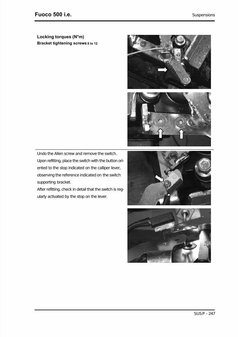
7/29/2019 Gilera Fuoco 500 i.e. (EN)
http://slidepdf.com/reader/full/gilera-fuoco-500-ie-en 247/329
Locking torques (N*m)
Bracket tightening screws 8 to 12
Undo the Allen screw and remove the switch.
Upon refitting, place the switch with the button ori-
ented to the stop indicated on the calliper lever,
observing the reference indicated on the switchsupporting bracket.
After refitting, check in detail that the switch is reg-
ularly activated by the stop on the lever.
Fuoco 500 i.e. Suspensions
SUSP - 247

7/29/2019 Gilera Fuoco 500 i.e. (EN)
http://slidepdf.com/reader/full/gilera-fuoco-500-ie-en 248/329
Undo the two pad pin screws; remove the pads
with the spring.
Upon refitting, tighten the two screws to the pre-
scribed torque and use threadlock.Upon refitting, adjust the cable properly so that the
switch is pushed when the system is unlocked.
Refit the spring/toothed sector unit, hold the crank-
case in a perfectly horizontal and stable position,
place the spring/toothed sector unit keeping it per-
fectly perpendicular to the bearing already fitted on
the crankcase; if necessary, slightly hit the unit
shaft end with a mallet and protect the thread by
screwing in a nut.
Suspensions Fuoco 500 i.e.
SUSP - 248

7/29/2019 Gilera Fuoco 500 i.e. (EN)
http://slidepdf.com/reader/full/gilera-fuoco-500-ie-en 249/329
Fit the pinion and align the reference on the pinion
teeth with the reference indicated on the second
slot of the toothed sector.
Grease the pinion and the toothed sector with spe-
cific grease.
Refit the toothed sector spacer.
Recommended products
MONTBLANC MOLYBDENUM GREASE MON-TBLANC MOLYBDENUM GREASE
Grease with molybdenum disulphide
Lubricate the interference areas, match the crank-
case halves with slight hits of a mallet to get them
into contact.
Place the flexible transmission supporting bracket,refit the four screws, screw them to the prescribed
torque.
Locking torques (N*m)
Gear motor crankcase halves couplingscrews 11 to 13
Refit the electric motor; check the position is cor-
rect by means of the reference indicated during
removal.
The motor should be so positioned that it does not
protrude from the reduction unit mould, see figure.
Tighten the screws to the prescribed torque.
Locking torques (N*m)
Electric motor coupling screws 11 to 13
Fuoco 500 i.e. Suspensions
SUSP - 249

7/29/2019 Gilera Fuoco 500 i.e. (EN)
http://slidepdf.com/reader/full/gilera-fuoco-500-ie-en 250/329
Place the moulded washer of the flexible trans-
mission control lever shaft and the tongue.
Refit the flexible transmission control lever as
shown in the figure.
Refit the potentiometer (not forcing in the D-type
connector ensures a sole position) with the con-
nector directed to the opposite side of the hydraulic
pump.
Refit the hydraulic pump on the gear motor body
and tighten the screws to the prescribed torque.
Fit but not tighten the pump stem coupling screw
and refit the plastic protection cap. The synchronisation procedure should be com-
plete when the installation is finished.
Locking torques (N*m)
Gear motor hydraulic pump tighteningscrews 11 to 13
Remove the retaining Seeger ring of the bearing
of the flexible transmission lever control shaft
bearing.
Remove the bearing with the specific tool.
Specific tooling
020376Y Adaptor handle
020441Y 26 x 28 mm adaptor
020362Y 12 mm guide
Suspensions Fuoco 500 i.e.
SUSP - 250

7/29/2019 Gilera Fuoco 500 i.e. (EN)
http://slidepdf.com/reader/full/gilera-fuoco-500-ie-en 251/329
Extract the electric motor bearing with the specific
tool.
Specific tooling
020376Y Adaptor handle
020375Y 28 x 30 mm adaptor
020363Y 20-mm guide
Hold the crankcase in a perfectly horizontal posi-
tion, heat it with a specific heat gun at about 120 °
C, use the specific tool to fit the bearing of the flex-
ible transmission lever control shaft. Hit slightlywith a mallet if necessary.
Refit the bearing check Seeger ring.
Specific tooling
020151Y Air heater
020376Y Adaptor handle
020362Y 12 mm guide
020357Y 32x35-mm Adaptor
Hold the crankcase in a perfectly horizontal posi-
tion, heat it with a specific heat gun at about 120 °
C, use the specific tool to fit the bearing of the
electric motor. Hit slightly with a mallet if necessa-
ry.
Specific tooling
020363Y 20-mm guide
020358Y 37x40-mm Adaptor
020151Y Air heater
Fuoco 500 i.e. Suspensions
SUSP - 251

7/29/2019 Gilera Fuoco 500 i.e. (EN)
http://slidepdf.com/reader/full/gilera-fuoco-500-ie-en 252/329
020376Y Adaptor handle
Remove the spring/toothed sector unit from its fit-
ting, slightly hit with a mallet if necessary to release
the unit.
Extract the bearing of the spring/toothed sector
unit with the specific tool.
Specific tooling
001467Y002 Driver for OD 73 mm bearing
Extract the bearing of the electric motor with the
specific tool.
Hold the crankcase in a perfectly horizontal posi-
tion, heat it with a specific heat gun at about 120 °
C, use the specific tool to fit the bearing of thespring/toothed sector unit. Hit slightly with a mallet
if necessary.
Specific tooling
020360Y 52x55-mm Adaptor
020151Y Air heater
020376Y Adaptor handle
Suspensions Fuoco 500 i.e.
SUSP - 252

7/29/2019 Gilera Fuoco 500 i.e. (EN)
http://slidepdf.com/reader/full/gilera-fuoco-500-ie-en 253/329
Hold the crankcase in a perfectly horizontal posi-
tion, heat it with a specific heat gun at about 120 °
C, use the specific tool to fit the bearing of the
electric motor. Hit slightly with a mallet if necessa-
ry.
Specific tooling
020363Y 20-mm guide
020151Y Air heater
020376Y Adaptor handle
020477Y 37 mm adaptor
Before removing the gear motor:
Disable the suspension lock.
Remove the legshield.
With the set nut indicated in the picture, remove
the tensioning cable of the suspension locking me-
chanical calliper.
Remove the electrical connection of the gear mo-
tor position potentiometer.
Remove the electrical connection of the gearedmotor electric motor.
Fuoco 500 i.e. Suspensions
SUSP - 253

7/29/2019 Gilera Fuoco 500 i.e. (EN)
http://slidepdf.com/reader/full/gilera-fuoco-500-ie-en 254/329
Disconnect the hydraulic pipes between the pump
and the sliding stem locking clamps. Empty the
system and use a container to collect the brake
fluid.CAUTION
ELIMINATE ANY REMAINING BRAKE FLUID SPILLS.
WARNING: BRAKE FLUID IS HIGHLY POISONOUS. DONOT INGEST OR SWALLOW. IF ACCIDENTALLY SWAL-LOWED, DRINK LARGE QUANTITIES OF MILK OR WATERAND SEEK MEDICAL ADVICE IMMEDIATELY. BRAKEFLUID DESTROYS SKIN AND OCULAR TISSUE. IF YOUACCIDENTALLY SPILL BRAKE FLUID ON YOURSELF,TAKE OFF YOUR CLOTHES, WASH WITH HOT WATERAND SOAP AND SEEK MEDICAL ADVICE IMMEDIATELY.IF BRAKE FLUID GETS ACCIDENTALLY IN CONTACTWITH YOUR EYES, RINSE WITH ABUNDANT FRESH WA-TER AND SEEK MEDICAL ADVICE IMMEDIATELY. KEEPBRAKE FLUID OUT OF THE REACH OF CHILDREN.
Remove the 3 fixing screws indicated and remove
the whole gear motor.
Use a screwdriver to remove the plastic access
cover to the pump joint/gear motor
Undo the pump joint screw.
Undo the two gear motor pump locking screws.
Suspensions Fuoco 500 i.e.
SUSP - 254

7/29/2019 Gilera Fuoco 500 i.e. (EN)
http://slidepdf.com/reader/full/gilera-fuoco-500-ie-en 255/329
Undo the two potentiometer screws.
Upon refitting, plug the potentiometer in D-type
connector, afterwards place it with its electric con-
nection directed to the opposite side of the pump.
Remove the nut indicated in the figure, if neces-
sary lock the lever with a vice making sure not to
spoil the surface.
In case of difficulties when removing the lever, use
the specific tool.
Remove the tongue and then, the moulded wash-
er.
Specific tooling
020234y extractor
Fuoco 500 i.e. Suspensions
SUSP - 255

7/29/2019 Gilera Fuoco 500 i.e. (EN)
http://slidepdf.com/reader/full/gilera-fuoco-500-ie-en 256/329
Remove the three fixing screws of the electric mo-
tor.
It is important to mark the direction of the electric
motor position in order to refit it correctly.
Remove the four screws indicated in the figure,
remove the flexible transmission supporting brack-
et, separate the two crankcase halves, if neces-
sary, use a rubber mallet to hit the flexibletransmission lever in order to separate the two
crankcases.
Electrical devices test
PRESSURE SWITCH
1: PRESSURE SWITCH
2: HORN SOLENOID
Suspensions Fuoco 500 i.e.
SUSP - 256
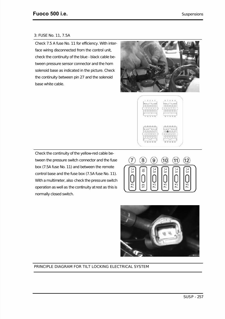
7/29/2019 Gilera Fuoco 500 i.e. (EN)
http://slidepdf.com/reader/full/gilera-fuoco-500-ie-en 257/329
3: FUSE No. 11, 7.5A
Check 7.5 A fuse No. 11 for efficiency. With inter-
face wiring disconnected from the control unit,
check the continuity of the blue - black cable be-
tween pressure sensor connector and the horn
solenoid base as indicated in the picture. Check
the continuity between pin 27 and the solenoid
base white cable.
Check the continuity of the yellow-red cable be-
tween the pressure switch connector and the fuse
box (7.5A fuse No. 11) and between the remotecontrol base and the fuse box (7.5A fuse No. 11).
With a multimeter, also check the pressure switch
operation as well as the continuity at rest as this is
normally closed switch.
PRINCIPLE DIAGRAM FOR TILT LOCKING ELECTRICAL SYSTEM
Fuoco 500 i.e. Suspensions
SUSP - 257

7/29/2019 Gilera Fuoco 500 i.e. (EN)
http://slidepdf.com/reader/full/gilera-fuoco-500-ie-en 258/329
KEY
1. Geared motor
2. Brake calliper sensor
3. Tilt unlocking-locking control switch4. Potentiometer
5. Rider presence sensor
6. Left speed sensor
7. Right speed sensor
8. Diagnostic tester series line
9. Engine control unit
10. +Direct battery
11. +Live battery
12. To light switch
13. Fuse No. 4; 20A
14. Light remote control
15. Pressure switch
16. Horn remote control
17. Instrument panel
18. Tilt locking system control unit
GEARED MOTOR
Suspensions Fuoco 500 i.e.
SUSP - 258

7/29/2019 Gilera Fuoco 500 i.e. (EN)
http://slidepdf.com/reader/full/gilera-fuoco-500-ie-en 259/329
1: GEAR MOTOR
With the interface wiring disconnected from the
control unit, check the continuity between pin 28
and the white-red cable, between pin 38 and the
blue cable on the geared motor connector
Fuoco 500 i.e. Suspensions
SUSP - 259

7/29/2019 Gilera Fuoco 500 i.e. (EN)
http://slidepdf.com/reader/full/gilera-fuoco-500-ie-en 260/329
With the interface wiring disconnected from the
control unit, check the continuity of the geared mo-
tor winding placing the multimeter probes on pins
28 and 38 as indicated in the figure.
TILT LOCKING-UNLOCKING SWITCH
0: REST POSITION
1: LOCKING POSITION2: UNLOCKING POSITION
Suspensions Fuoco 500 i.e.
SUSP - 260

7/29/2019 Gilera Fuoco 500 i.e. (EN)
http://slidepdf.com/reader/full/gilera-fuoco-500-ie-en 261/329
3: ROLL LOCK-UNLOCK SWITCH
With the interface wiring disconnected from the
control unit, check the continuity of the electrical
lines between the interface wiring and the roll lock-
unlock switch:
Pin 26 and green - grey cable
Pin 35 and violet - black cable
Pin 33 and yellow - blue cable
Also check that the above indicated electrical lines
are insulated from the ground.
Check the continuity between the black cable on
the connector and a ground point on the chassis.
With a multimeter, check the operation of the tilt
locking-unlocking switch referring to the diagram
indicated in the figure.KEY
1. GROUND
2. LOCK
3. REST
4. UNLOCK
TILT LOCKING CALLIPER SENSOR
Fuoco 500 i.e. Suspensions
SUSP - 261

7/29/2019 Gilera Fuoco 500 i.e. (EN)
http://slidepdf.com/reader/full/gilera-fuoco-500-ie-en 262/329
1: ROLL LOCK CALLIPER SENSOR
The roll lock calliper sensor is a normally opened
switch. Check its correct operation with a multi-
meter.
With the interface wiring disconnected from the
control unit, check the continuity between pin 34
and the brown cable of the roll lock gripper sensor
connector on the system side.
Check the continuity of the connector black cable
and a ground point on the chassis
Suspensions Fuoco 500 i.e.
SUSP - 262

7/29/2019 Gilera Fuoco 500 i.e. (EN)
http://slidepdf.com/reader/full/gilera-fuoco-500-ie-en 263/329
Also check that the flexible transmission control
lever activates the limit stop switch properly.
POTENTIOMETER
1: POTENTIOMETER
Fuoco 500 i.e. Suspensions
SUSP - 263

7/29/2019 Gilera Fuoco 500 i.e. (EN)
http://slidepdf.com/reader/full/gilera-fuoco-500-ie-en 264/329
With the interface wiring connected to the control
unit, secure the vehicle on its centre stand and
switch to "ON". Select the reading scale on 20 V.
Insert the multimeter probes on pins 17 and 25.
Check that the voltage in the activated locking
condition is 4V and 1V in the locking rest condition.
With the interface wiring disconnected from the
control unit, check the continuity between pin 17
and the yellow cable of the potentiometer connec-
tor, between pin 25 and the green-blue cable,between pin 11 and the orange-blue cable. Also
check that these lines are insulated from each oth-
er and ground.
RIDER PRESENCE SENSOR
Suspensions Fuoco 500 i.e.
SUSP - 264

7/29/2019 Gilera Fuoco 500 i.e. (EN)
http://slidepdf.com/reader/full/gilera-fuoco-500-ie-en 265/329
1: RIDER DETECTION SENSOR
With the interface wiring disconnected from the
control unit and connected to the system, check
the following conditions:
pin 17 - 36: resistance 15 - 18 kOhm when the rider
is not seated on the saddle.
pin 17 - 36: resistance of about 3 kOhm when the
rider is seated on the saddle
Check the continuity between the interface wiring
pin 17 and the yellow cable of the rider presence
connector.
Check the continuity between the interface wiring
pin 36 and violet cable of the rider presence con-
nector.
TONE WHEEL SENSOR
Fuoco 500 i.e. Suspensions
SUSP - 265
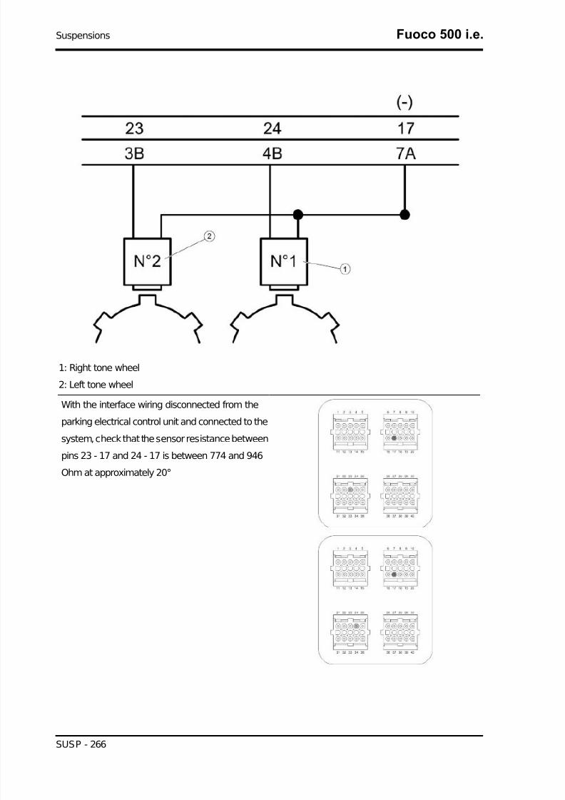
7/29/2019 Gilera Fuoco 500 i.e. (EN)
http://slidepdf.com/reader/full/gilera-fuoco-500-ie-en 266/329
1: Right tone wheel
2: Left tone wheel
With the interface wiring disconnected from the
parking electrical control unit and connected to the
system, check that the sensor resistance between
pins 23 - 17 and 24 - 17 is between 774 and 946
Ohm at approximately 20°
Suspensions Fuoco 500 i.e.
SUSP - 266

7/29/2019 Gilera Fuoco 500 i.e. (EN)
http://slidepdf.com/reader/full/gilera-fuoco-500-ie-en 267/329
With the interface wiring disconnected from the
control unit, check the continuity between pin 23
and the red cable of the LEFT wheel turning sen-
sor connector; the continuity between pin 17 and
the brown cables of the LEFT and RIGHT wheel
turning sensors; and between pin 24 and the red
cable of the RIGHT wheel turning sensor.
In case of failures, check the continuity between
pin 23 and the connector green cable on the fuel
tank after removing the chassis central cover; be-
tween pin 17 and the yellow cables on both con-nectors; between pin 24 and the red cable on the
connector.
With the interface wiring disconnected from the
control unit and the connectors disconnected from
wheel turning sensors, check that pin 23 - 17 and
24 - 17 are insulated from each other and from
ground.
Fuoco 500 i.e. Suspensions
SUSP - 267

7/29/2019 Gilera Fuoco 500 i.e. (EN)
http://slidepdf.com/reader/full/gilera-fuoco-500-ie-en 268/329
With a feeler gauge, check that the air gap be-
tween the screw head and the sensor is between
0.35 and 1 mm
Wheel alignment
Tool fitting
How to use the tools
• Check that tyre pressure is correct.
• Park the vehicle on level, smooth and
even ground.
• Rest the vehicle on its centre stand.
• Make sure that the parking system is
disengaged.
• Lift the front wheels as shown in the
photograph
Suspensions Fuoco 500 i.e.
SUSP - 268

7/29/2019 Gilera Fuoco 500 i.e. (EN)
http://slidepdf.com/reader/full/gilera-fuoco-500-ie-en 269/329
• Check that the wheel rims rotate even-
ly and whether there is abnormal clear-
ance in bearings and suspensions.
• Make sure that the steering control
shows no signs of abnormal clearance
in joints and bearings. Otherwise, cor-
rect this and then adjust them.
Characteristic
Front tyre pressure (with passenger)
1.6 bar (1.8 bar)
Rear tyre pressure (with passenger)
2.4 bar (2.6 bar)• Get the vehicle off the stand, back on
the ground.
• Remove the right lower coupling plate
of the half-arm by undoing the screws
indicated in the picture.
• Remove the right upper screw and the
left bottom screw of the parallelogram
unit.
Fuoco 500 i.e. Suspensions
SUSP - 269
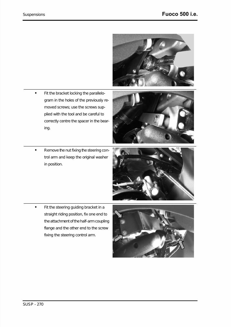
7/29/2019 Gilera Fuoco 500 i.e. (EN)
http://slidepdf.com/reader/full/gilera-fuoco-500-ie-en 270/329
• Fit the bracket locking the parallelo-
gram in the holes of the previously re-
moved screws; use the screws sup-
plied with the tool and be careful tocorrectly centre the spacer in the bear-
ing.
• Remove the nut fixing the steering con-
trol arm and keep the original washer
in position.
• Fit the steering guiding bracket in a
straight riding position, fix one end to
the attachment of the half-arm coupling
flange and the other end to the screwfixing the steering control arm.
Suspensions Fuoco 500 i.e.
SUSP - 270

7/29/2019 Gilera Fuoco 500 i.e. (EN)
http://slidepdf.com/reader/full/gilera-fuoco-500-ie-en 271/329
• Place the frame so that the sliders
come into contact with the rim maxi-
mum diameter but without interfering
with the tyre. If required, reposition the
frame by operating the 3 adjustable
support feet.
• Fit the frame locking bracket
• Make sure the frame is adequately
centred by checking with a gauge that
the lugs along the vertical axis show
the standard protrusion.
Fuoco 500 i.e. Suspensions
SUSP - 271

7/29/2019 Gilera Fuoco 500 i.e. (EN)
http://slidepdf.com/reader/full/gilera-fuoco-500-ie-en 272/329
• Check that the pointers of both tyres
are correctly aligned, as shown in the
picture. Maximum misalignment al-
lowed: 4 notches.• Use tool 020647Y028 for LT version
with extended track.
Specific tooling
020646Y Parallelogram and steering position-
ing tool
020647Y Toe-in checking tool
020647Y028 MP3 LT Toe-in tool (tricycle)
Rear
Removing the rear wheelBefore removing the rear wheel, support the vehi-
cle properly and operate the parking brake so as
to facilitate removing the wheel fixing screws.
- Remove the exhaust silencer.
- Undo the screw fixing the right shock absorber to
the clamp.
- Undo the two screws fixing the clamp to the en-
gine.
Suspensions Fuoco 500 i.e.
SUSP - 272

7/29/2019 Gilera Fuoco 500 i.e. (EN)
http://slidepdf.com/reader/full/gilera-fuoco-500-ie-en 273/329
- Undo the two screws fixing the clamp to the cen-
tre stand.
- Remove the cotter pin and collect the cap.
- Unscrew the wheel fixing nut and collect the
spacer.
- Unscrew the clamp.
- Collect the conical spacer.
- Undo the five wheel fixing screws and remove the
wheel.
Fuoco 500 i.e. Suspensions
SUSP - 273

7/29/2019 Gilera Fuoco 500 i.e. (EN)
http://slidepdf.com/reader/full/gilera-fuoco-500-ie-en 274/329
Refitting the rear wheel
To fit, follow the removal steps but in the reverse
sequence, being careful to fit the spacers on the
wheel axle as shown in the picture.
Locking torques (N*m)
Silencer arm clamping screws 27 - 30 Rear wheel axle nut 104 to 126 Shock absorber-crank-case attachment bracket 20 to 25 Lower shockabsorber clamping screw 33 - 41 Nm Rear brakecalliper fixing screws 25 - 30 Nm
Swing-arm
Removal
- Rest the scooter on its centre stand.
- Remove the retainer fixing the swinging arm to
the engine, unscrew the nut and remove the bolt.
Suspensions Fuoco 500 i.e.
SUSP - 274

7/29/2019 Gilera Fuoco 500 i.e. (EN)
http://slidepdf.com/reader/full/gilera-fuoco-500-ie-en 275/329
- Remove the silent-blocks.
- Remove the retainer fixing the swinging arm to
the frame: undo the screw.
- Remove the pin.
- Unscrew the nut of the set screw bushing.
Fuoco 500 i.e. Suspensions
SUSP - 275

7/29/2019 Gilera Fuoco 500 i.e. (EN)
http://slidepdf.com/reader/full/gilera-fuoco-500-ie-en 276/329
- From the inside loosen the set screw bushing
until the swinging arm is free.
- Remove the swinging arm.
- Check the entire swinging arm assembly.
- Check all the components- Teflon bushings, si-
lent-blocks, roller bushings, spacers.
- Replace the work components that cause exces-sive clearance on the rear suspension.
Overhaul
- Properly support the swinging arm in the vice.
- Check there is no jamming in the movement of the joint connecting the swinging arm on the engine
side to the swinging arm on the frame side.
- In order to check the clearance of the swinging arm on the frame side, prepare a retainer using the
fixing pin of the swinging arm on the frame and two rings from the special tool 020229Y. Alternatively,
use two washers with 12-mm inside diameter for pins, minimum 30-mm outside diameter and 4-mm
thick at least.
- Check there is no sticking in the rotation.
- Check the axial clearance of the swinging arm on
the chassis side
Characteristic
Standard clearance
0.40 - 0.60 mm
Allowable limit after use:
1.5 mm
Suspensions Fuoco 500 i.e.
SUSP - 276

7/29/2019 Gilera Fuoco 500 i.e. (EN)
http://slidepdf.com/reader/full/gilera-fuoco-500-ie-en 277/329
- Separate the swinging arm on the engine side
from the vehicle side arm.
- Remove the plastic bushings and the internal
spacer shown in the picture.
- Remove the pin connecting the engine swinging
arm - frame swinging arm.
The operations below are described once but ap-
ply to both sides of the swinging arm.
- Remove the internal spacer.
- Using a suitable pin remove the roller casings asshown in the photographs
- Using an appropriate tool plant new roller cas-
ings, being careful to position the bearings with the
O-rings facing outwards
Specific tooling
020244Y 15-mm diameter punch
Characteristic
Length of the swinging arm tube on the engineside:
L 140.5 ±0.7 mm
Chassis side swinging arm plastic bushingshim:
3.5 ±0.05 mm
Length of the internal swinging arm spacer onthe frame side:
Fuoco 500 i.e. Suspensions
SUSP - 277
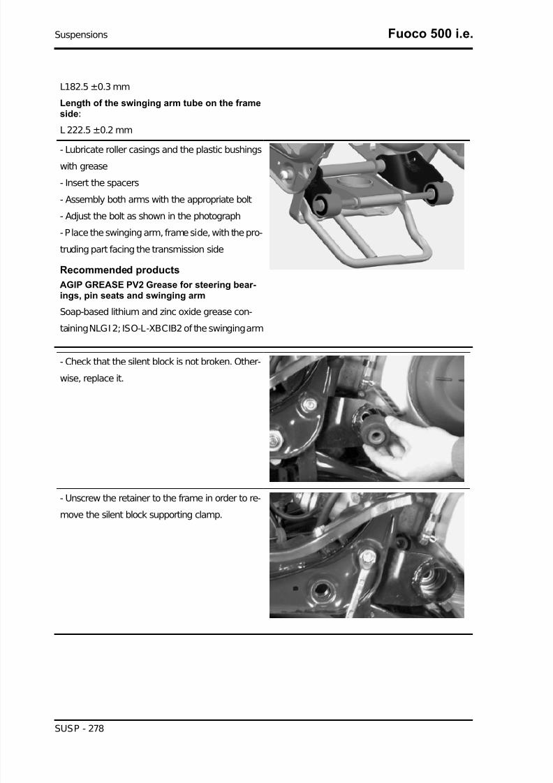
7/29/2019 Gilera Fuoco 500 i.e. (EN)
http://slidepdf.com/reader/full/gilera-fuoco-500-ie-en 278/329
L182.5 ±0.3 mm
Length of the swinging arm tube on the frameside:
L 222.5 ±0.2 mm
- Lubricate roller casings and the plastic bushings
with grease
- Insert the spacers
- Assembly both arms with the appropriate bolt
- Adjust the bolt as shown in the photograph
- Place the swinging arm, frame side, with the pro-
truding part facing the transmission side
Recommended productsAGIP GREASE PV2 Grease for steering bear-ings, pin seats and swinging arm
Soap-based lithium and zinc oxide grease con-
taining NLGI 2; ISO-L-XBCIB2 of the swinging arm
- Check that the silent block is not broken. Other-
wise, replace it.
- Unscrew the retainer to the frame in order to re-
move the silent block supporting clamp.
Suspensions Fuoco 500 i.e.
SUSP - 278

7/29/2019 Gilera Fuoco 500 i.e. (EN)
http://slidepdf.com/reader/full/gilera-fuoco-500-ie-en 279/329
Refitting
For correct installation of the swinging arm on the
vehicle, proceed as follows:
1. Position the silent block supporting clamp with
part 3 inserted, and slightly tighten part 1
2. Position the swinging arm, inserting part 2
3. Tighten part 3 to the prescribed torque
4. Screw on and tighten part 4 to the prescribed
torque
5. Screw on and tighten part 5 to the prescribed
torque
6. Tighten part 1 to the prescribed torque
Insert the swinging arm - engine bolt and tighten
to the prescribed torque
Fuoco 500 i.e. Suspensions
SUSP - 279

7/29/2019 Gilera Fuoco 500 i.e. (EN)
http://slidepdf.com/reader/full/gilera-fuoco-500-ie-en 280/329
SWINGING ARM FITTING
Name Torque in Nm
Part 1 98 ÷118Part 3 5 ÷7
Part 4 88.5 ÷108Part 5 54 ÷60Bolt for swinging arm, engine side / swinging arm, frame side 32.5 ÷40
Shock absorbers
Removal
Proceed as follows:
- place the scooter on its centre stand;
- lift the engine a little with a jack so as to free the
two shock absorbers;
- remove the exhaust silencer;
- undo the shock absorber spring assembly clamp-
ing screw from the support fixed to the engine on
the one side and from that fixed to the muffler on
the other;
- unscrew the two upper nuts (one on each side)
fixing the shock absorber spring assembly to theframe and remove the shock absorbers.
Refitting
Carry out the previous operations but in reverse order.
Locking torques (N*m)
Suspensions Fuoco 500 i.e.
SUSP - 280
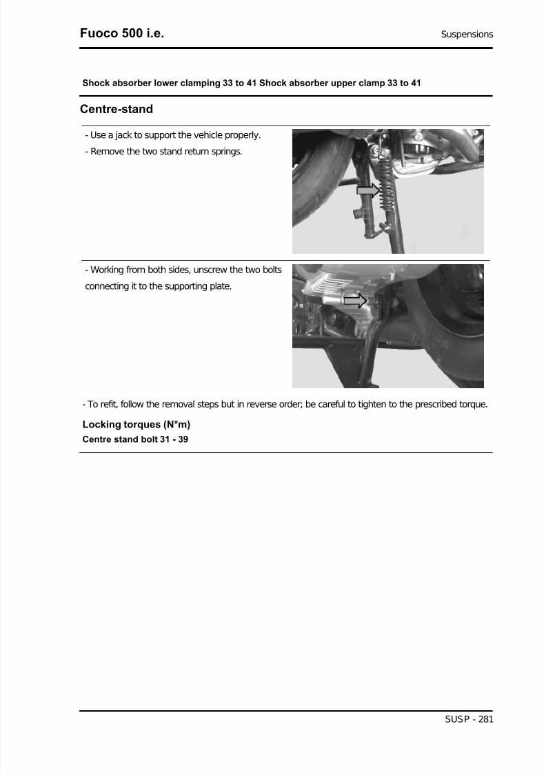
7/29/2019 Gilera Fuoco 500 i.e. (EN)
http://slidepdf.com/reader/full/gilera-fuoco-500-ie-en 281/329
Shock absorber lower clamping 33 to 41 Shock absorber upper clamp 33 to 41
Centre-stand
- Use a jack to support the vehicle properly.
- Remove the two stand return springs.
- Working from both sides, unscrew the two boltsconnecting it to the supporting plate.
- To refit, follow the removal steps but in reverse order; be careful to tighten to the prescribed torque.
Locking torques (N*m)
Centre stand bolt 31 - 39
Fuoco 500 i.e. Suspensions
SUSP - 281
7/29/2019 Gilera Fuoco 500 i.e. (EN)
http://slidepdf.com/reader/full/gilera-fuoco-500-ie-en 282/329
INDEX OF TOPICS
BRAKING SYSTEM BRAK SYS

7/29/2019 Gilera Fuoco 500 i.e. (EN)
http://slidepdf.com/reader/full/gilera-fuoco-500-ie-en 283/329
This section è is dedicated to the description of the braking system components.
Rear brake calliper
Removal
- Remove the rear wheel.
- Undo the screws connecting the air filter to the
crankcase so that the wrenches can be inserted.
- Undo the two fixing screws and remove the cal-
liper.
N.B.
IF IT IS NECESSARY TO REPLACE OR SERVICE THEBRAKE CALLIPER, BEFORE REMOVING THE FITTINGSFIXING THE CALLIPER TO THE SUPPORT BRACKET,FIRST LOOSEN THE OIL HOSE FITTING AFTER HAVINGEMPTIED THE SYSTEM OF THE CIRCUIT BEING EXAM-INED.
Overhaul
Proceed as follows:
1) remove the two male hexagonal screws (1) and
take out the two pads (10);2) remove the two male hexagonal screws (2) and
remove the reaction plate (3);
3) take out the fixed plate (4) from the guide;
4) remove the internal elements from the floating
body (5) with the help of short blows of com-
pressed air through the brake fluid pipe in order to
facilitate the expulsion of pistons (6).
5) Check:
- that the plates and the body are whole and in
good condition;
- that the cylinder and the floating body of the cal-
liper do not show signs of scratches or erosion,
otherwise replace the entire calliper;
- that the guides of the fixed plate are not scratched
or eroded, otherwise replace the entire plate;
- that the brake pad check spring works properly.
Refitting
Fuoco 500 i.e. Braking system
BRAK SYS - 283

7/29/2019 Gilera Fuoco 500 i.e. (EN)
http://slidepdf.com/reader/full/gilera-fuoco-500-ie-en 284/329
1) insert the pistons (6) and the sealing rings (7) in
the body;
2) place the guide rubbers (8) and refit the fixed
plate (4);
3) assemble the reaction plate (3) tightening the
screws (2), insert the brake pad check spring (9)
and then the pads, fixing them with the corre-
sponding screws (1);
5) place the calliper on the disc and lock it to the
strut by tightening the fixing screws;
6) fix the pipe joint on the calliper at the prescribed
torque.Functioning
This is a floating type calliper.
It takes advantage of the action and reaction prin-
ciple to obtain the thrust for both pads.
The body and the reaction plate body work inte-
grally and can move axially with respect of the
fixed plate that is integral to the strut.
The pistons, forced by pressure to push the pad to
the disc, cause the reaction plate to push in turn
the other pad towards the disc.
The brake pad lock spring
1. Pad fixing screws
2. Reaction plate fixing screws
3. Reaction plate
4. Fixed plate
5. Floating body
6. Piston
7. Piston sealing rings
8. Guide protection rubber rings
9. Brake pad check spring
10. Brake pads
CAUTION
ALL THE SEALS AND GASKETS MUST BE REPLACED EV-ERY TIME THE CALLIPER IS SERVICED.
Locking torques (N*m)
Brake fluid tube-calliper fitting 20 to 25 Pad fas-tening pin 20 to 25
Braking system Fuoco 500 i.e.
BRAK SYS - 284

7/29/2019 Gilera Fuoco 500 i.e. (EN)
http://slidepdf.com/reader/full/gilera-fuoco-500-ie-en 285/329
Refitting
- To fit the rear brake calliper, follow the removal steps but in reverse order; be careful to tighten the
screws to the prescribed torque.
Locking torques (N*m)
Screw tightening calliper to support 20 to 25
Front brake calliper
Removal
- The operations described refer to only one cal-
liper but apply to both.
- Remove the wheel.
- Undo the two fixing screws to the plate and re-
move the calliper.
Overhaul
- Remove the rear brake calliper.
- Suitably hold the brake calliper in a clamp
- Remove the two calliper coupling screws as
shown in the photo
- Remove the two pistons from the calliper body
with the aid of short blasts of compressed air
through the brake fluid holes
- Remove the dust ring and the O-ring of each half
calliper.
- Remove the O-rings in the half calliper.
N.B.
WHEN REMOVING THE O-RINGS, BE CAREFUL NOT TOSCRATCH THE HALF CALLIPER SEATS
Fuoco 500 i.e. Braking system
BRAK SYS - 285

7/29/2019 Gilera Fuoco 500 i.e. (EN)
http://slidepdf.com/reader/full/gilera-fuoco-500-ie-en 286/329
- Check that the pistons and their seats show no
scratches.
- Wash and blow all the components carefully
- Fit the O-rings and new dust guards
- Refit the pistons in their seats being careful to
lubricate with brake fluid
- Re-couple the half callipers and lock the two
screws at the specified torque
Locking torques (N*m)
Calliper coupling screw 22 ÷ 27
Refitting
Rear brake disc
Removal
- Remove the rear wheel.
- Loosen the nuts fixing the safety washers.
- Undo the two screws fixing the plate supporting
the calliper to the frame.
Braking system Fuoco 500 i.e.
BRAK SYS - 286

7/29/2019 Gilera Fuoco 500 i.e. (EN)
http://slidepdf.com/reader/full/gilera-fuoco-500-ie-en 287/329
- Remove the calliper supporting clamp.
- Remove the brake disc
Refitting
- To fit the rear brake disc, follow the removal steps but in reverse order; be careful to tighten the screws
to the prescribed torque using threadlock.
Recommended products
Loctite 243 Medium strength threadlock
Medium Loctite 243 threadlock
Locking torques (N*m)
Rear disc screws 5 - 6.5 Nm
Disc Inspection
Checking the disc is important; it must be perfectly
clean, with no sign of rust, oil or grease or any oth-
er dirt, and must show no signs of deep scoring.
Characteristic
New rear disc thickness
5 mm
Disc thickness at wear limit (rear)
3.5 mm
Fuoco 500 i.e. Braking system
BRAK SYS - 287

7/29/2019 Gilera Fuoco 500 i.e. (EN)
http://slidepdf.com/reader/full/gilera-fuoco-500-ie-en 288/329
- Remove the wheel and check using the appro-
priate tools that the axial run-out of the brake
surface is within the prescribed limits.
- If this is not the case, replace the disc and repeat
the test.
WHEN INSTALLING, THOROUGHLY CLEAN THE DISCAND ITS SEAT ON THE HUB.
Characteristic
Max. axial run-out
0.1 mm
Front brake disc
Removal
- The operations described refer to only one disc
but apply to both.
- Remove the wheel.
- Remove the brake calliper.
- Remove the cotter pin and remove the cap.
- Unscrew the fixing nut.
Braking system Fuoco 500 i.e.
BRAK SYS - 288

7/29/2019 Gilera Fuoco 500 i.e. (EN)
http://slidepdf.com/reader/full/gilera-fuoco-500-ie-en 289/329
- Remove the wheel hub.
- Unscrew the six bolts securing the disc to the
wheel hub.
- Remove the disc.
Refitting
- To fit the front brake disc, follow the removal steps but in reverse order; be careful to tighten the screws
to the prescribed torque using threadlock.
Recommended products
Loctite 243 Medium strength threadlock
Medium Loctite 243 threadlock
Locking torques (N*m)
Front disc screws 5 ÷ 6 Nm
Disc Inspection
Checking the disc is important; it must be perfectly clean, with no sign of rust, oil or grease or any other
dirt, and must show no signs of deep scoring.
Characteristic
Thickness of a new front disc
4.0 mm
Disc thickness at wear limit (front)
3.5 mm
Fuoco 500 i.e. Braking system
BRAK SYS - 289

7/29/2019 Gilera Fuoco 500 i.e. (EN)
http://slidepdf.com/reader/full/gilera-fuoco-500-ie-en 290/329
- Remove the wheel and check using the appro-
priate tools that the axial run-out of the brake
surface is within the prescribed limits.
- If this is not the case, replace the disc and repeat
the test.
WHEN INSTALLING, THOROUGHLY CLEAN THE DISCAND ITS SEAT ON THE HUB.
Characteristic
Max. axial run-out
0.1 mm
Front brake pads
Removal
- Remove the brake calliper.
- Remove the Benzing snap ring of the pad pin.
- Slide off the pin paying attention to collect the
retaining spring of the pads.
Braking system Fuoco 500 i.e.
BRAK SYS - 290

7/29/2019 Gilera Fuoco 500 i.e. (EN)
http://slidepdf.com/reader/full/gilera-fuoco-500-ie-en 291/329
- Remove the pads.
Characteristic
Minimum value
1.5 mm
Refitting
- Follow the removal steps but in reverse order; check that the Benzing snap ring of the pads is in good
conditions.
Rear brake pads
Removal
Proceed as follows:
- Remove the rear brake calliper
- Remove the two pins holding the brake pads.
- Remove the pads, paying attention to the pad re-
taining spring.
- Check the thickness of the pads.
If the thickness is less than the minimum value,
replace the pads with new pads.
Characteristic
Minimum value
1.5 mm
Refitting
- To fit the rear brake pads, follow the removal steps but in reverse order; be careful to tighten the screws
to the prescribed torque.
Locking torques (N*m)
Screws tightening the pad fixing pin 20 ÷ 25 Nm
Fill
Fuoco 500 i.e. Braking system
BRAK SYS - 291

7/29/2019 Gilera Fuoco 500 i.e. (EN)
http://slidepdf.com/reader/full/gilera-fuoco-500-ie-en 292/329
Rear - combined
For the procedure in question see «Highlighted operations» section.
Front
For the procedure in question see «Highlighted operations» section.
Brake pipes
Unscrew the braking splitter screw.
Disconnect the brake pipes removing the two met-
allic straps indicated in the figure.
Remove the brake oil tube fitting from the rigid pipe
inside the front suspension arm and loosen the
hydraulic joint fixing nut of the suspension locking
to release the brake pipes.
Remove legshield.
Remove front wheel and mudguard.
Disconnect the brake pipes from the calliper anddrain the brake fluid.
Then, remove the plastic and metallic straps.
Unscrew the brake pump pipes as indicated in the
figure.
Braking system Fuoco 500 i.e.
BRAK SYS - 292
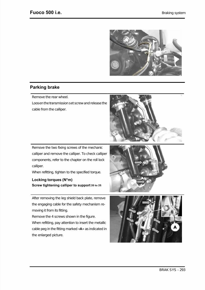
7/29/2019 Gilera Fuoco 500 i.e. (EN)
http://slidepdf.com/reader/full/gilera-fuoco-500-ie-en 293/329
Parking brake
Remove the rear wheel.
Loosen the transmission set screw and release the
cable from the calliper.
Remove the two fixing screws of the mechanic
calliper and remove the calliper. To check calliper
components, refer to the chapter on the roll lock
calliper.
When refitting, tighten to the specified torque.
Locking torques (N*m)
Screw tightening calliper to support 20 to 25
After removing the leg shield back plate, remove
the engaging cable for the safety mechanism re-
moving it from its fitting.
Remove the 4 screws shown in the figure.
When refitting, pay attention to insert the metallic
cable peg in the fitting marked «A» as indicated in
the enlarged picture.
Fuoco 500 i.e. Braking system
BRAK SYS - 293

7/29/2019 Gilera Fuoco 500 i.e. (EN)
http://slidepdf.com/reader/full/gilera-fuoco-500-ie-en 294/329
Remove the electric connection from the engaged
parking brake warning light switch.
Remove the parking brake cable from the lever by
operating the set screw indicated in the picture.
Braking system Fuoco 500 i.e.
BRAK SYS - 294

7/29/2019 Gilera Fuoco 500 i.e. (EN)
http://slidepdf.com/reader/full/gilera-fuoco-500-ie-en 295/329
INDEX OF TOPICS
COOLING SYSTEM COOL SYS

7/29/2019 Gilera Fuoco 500 i.e. (EN)
http://slidepdf.com/reader/full/gilera-fuoco-500-ie-en 296/329
Circuit diagram
This is a forced circulation cooling system, with continuous venting and air pressurisation.
Circulation takes places by a centrifugal pump driven by the countershaft.
The pump delivers the coolant to the thermal group.
The two-way thermostat support is connected in output to the head. One way is connected to the pump
and the other to the radiator (of the horizontal circulation type).
The radiator output is directly connected to the pump.
The expansion tank is connected in parallel to the radiator.
The radiator hot box is connected to the upper side of the expansion tank (in air).
The radiator cold box is connected to the lower side of the expansion tank (in the fluid).
When the engine is cold, the thermostat output to the radiator is closed, even though there is still a littleflow for de-aeration obtained by a hole into the closing plate.
In this case, the circulation into the thermal group is active to ensure an even heating.
Once the working temperature has been reached, the main circulation on radiator and expansion tank
starts.
With the small openings in the thermostat there is a flow overlapping (recirculation and main one).
When the temperature is higher, the thermostat allows excluding the recirculation to favour the main
circulation.
In this case, the flow is consistent in the expansion tank as well, and this ensures a continuous automatic
venting.
Cooling system Fuoco 500 i.e.
COOL SYS - 296

7/29/2019 Gilera Fuoco 500 i.e. (EN)
http://slidepdf.com/reader/full/gilera-fuoco-500-ie-en 297/329
For the system venting during the circuit filling step, there is a special union at the top of the head (see
filling rules).
To ensure cooling in case of poor dynamic ventilation, there is an electric fan controlled by the injection
system.
TECHNICAL SPECIFICATIONSSpecification Desc./Quantity
Cooling system capacity 1.8 lPrescribed fluid Mixture of 50% water and 50% fluid for sealed circuitsSealing pressure Cap calibrated at 0.9 bar
THERMOSTATSpecification Desc./Quantity
Type Wax-type, with deviatorStarts opening 90 ±2°C
ELECTRIC VENTILATIONSpecification Desc./Quantity
Type With pistonElectric ventilation starts at 105°CElectric ventilation stops at 100°C
WATER PUMPSpecification Desc./Quantity
Type CentrifugalControl Coaxial at the countershaft
RADIATOR
Specification Desc./Quantity Type Aluminium, with horizontal circulation
EXPANSION TANKSpecification Desc./Quantity
Calibration Automatic bleeding, in parallel with the radiator
Electric fan check
- Connect the injection diagnostic tester and select
the «ERRORS» function in this menu.
- Check any failures in the electric fan control cir-
cuit (see «Injection»chapter)
Specific tooling
020680Y Diagnosis Tool
Fuoco 500 i.e. Cooling system
COOL SYS - 297
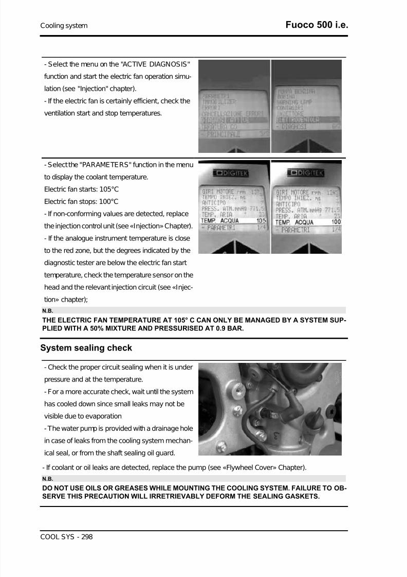
7/29/2019 Gilera Fuoco 500 i.e. (EN)
http://slidepdf.com/reader/full/gilera-fuoco-500-ie-en 298/329
- Select the menu on the "ACTIVE DIAGNOSIS"
function and start the electric fan operation simu-
lation (see "Injection" chapter).
- If the electric fan is certainly efficient, check the
ventilation start and stop temperatures.
- Select the "PARAMETERS" function in the menu
to display the coolant temperature.
Electric fan starts: 105°C
Electric fan stops: 100°C- If non-conforming values are detected, replace
the injection control unit (see «Injection» Chapter).
- If the analogue instrument temperature is close
to the red zone, but the degrees indicated by the
diagnostic tester are below the electric fan start
temperature, check the temperature sensor on the
head and the relevant injection circuit (see «Injec-
tion» chapter);
N.B.
THE ELECTRIC FAN TEMPERATURE AT 105° C CAN ONLY BE MANAGED BY A SYSTEM SUP-PLIED WITH A 50% MIXTURE AND PRESSURISED AT 0.9 BAR.
System sealing check
- Check the proper circuit sealing when it is under
pressure and at the temperature.
- For a more accurate check, wait until the system
has cooled down since small leaks may not bevisible due to evaporation
- The water pump is provided with a drainage hole
in case of leaks from the cooling system mechan-
ical seal, or from the shaft sealing oil guard.
- If coolant or oil leaks are detected, replace the pump (see «Flywheel Cover» Chapter).
N.B.
DO NOT USE OILS OR GREASES WHILE MOUNTING THE COOLING SYSTEM. FAILURE TO OB-SERVE THIS PRECAUTION WILL IRRETRIEVABLY DEFORM THE SEALING GASKETS.
Cooling system Fuoco 500 i.e.
COOL SYS - 298

7/29/2019 Gilera Fuoco 500 i.e. (EN)
http://slidepdf.com/reader/full/gilera-fuoco-500-ie-en 299/329
Coolant replacement
System filling instructions
- Prepare the mixture of 50% water and 50% cool-
ant.
- Fill the system to reach a level ranging between
the MIX and MAX levels indicated in the expansion
tank filler.
- Do not close the expansion tank with the cap.
- Use a transparent hose to connect the venting
union with the expansion tank filler.
- Loosen the vent and start the engine.
- Keep it open until the air has been fully vented.
- Close the bleed screw.
- Stop the engine.
- Restore the level into the expansion tank and tighten the cap.
- Start the engine and let it warm up to reach the electric ventilation temperature.
- Stop the engine.
- Restore the level with cold engine.
CAUTION
ELECTRIC VENTILATION IS CONTROLLED BY THE TEMPERATURE MEASURED AT THE HEAD.THE ELECTRIC VENTILATION START DOES NOT MEAN THAT THE VENTING HAS BEEN COM-PLETED.
VENTING IS COMPLETE WHEN THE EXPANSION TANK TEMPERATURE RISES.
Water pump
Water pump
If noise or loss of liquid at the drain hole of the water pump is discovered, replace the flywheel cover
and the water pump as described in the "Flywheel Cover" Chapter.
Proceed to carry out a few preliminary operations as described below:
• Place the vehicle on its centre stand and on flat ground.
• Remove the bodywork components as described in the "Bodywork" Chapter.
Fuoco 500 i.e. Cooling system
COOL SYS - 299

7/29/2019 Gilera Fuoco 500 i.e. (EN)
http://slidepdf.com/reader/full/gilera-fuoco-500-ie-en 300/329
• Remove the muffler to access the flywheel cover as described in the "Removing the Engine
from the Vehicle" Chapter.
• Empty the cooling system, removing the hoses located on the water pump cover and the
loading cap located on the expansion tank.CAUTION
THIS OPERATION MUST BE CARRIED OUT WHEN THE ENGINE IS COLD.
• Remove the water pump cover shown
in the figure by loosening the 6 fasten-
ing screws.
• Proceed to partially drain the circuit as
described in the "Engine" Chapter.
• Once the fault has been fixed and all
components have been replaced, fill
and purge the system again.
N.B.
FOR CHANGING THE COOLANT AND BLEEDING THESYSTEM, SEE THE "COOLANT CHANGE" SECTION.
Characteristic
Cooling system
approx. 1.8 l
Removing the water pump cover:
- Check that the water pump cover is not deformed
or dented.
- Check that the sealing O-ring is in good working
order.
- Otherwise, replace the component.
- Correctly fit a new O-ring, do not allow it to come into contact with grease or oil.
CAUTION
FAILURE TO OBSERVE THIS PRECAUTION WILL IRRETRIEVABLY DEFORM THE O-RING.
- Refit the water pump cover and tighten the 6 fixing screws to the prescribed torque.
Locking torques (N*m)
Water pump cover screws 3 ÷ 4
See also
Flywheel cover
Engine
Cooling system Fuoco 500 i.e.
COOL SYS - 300
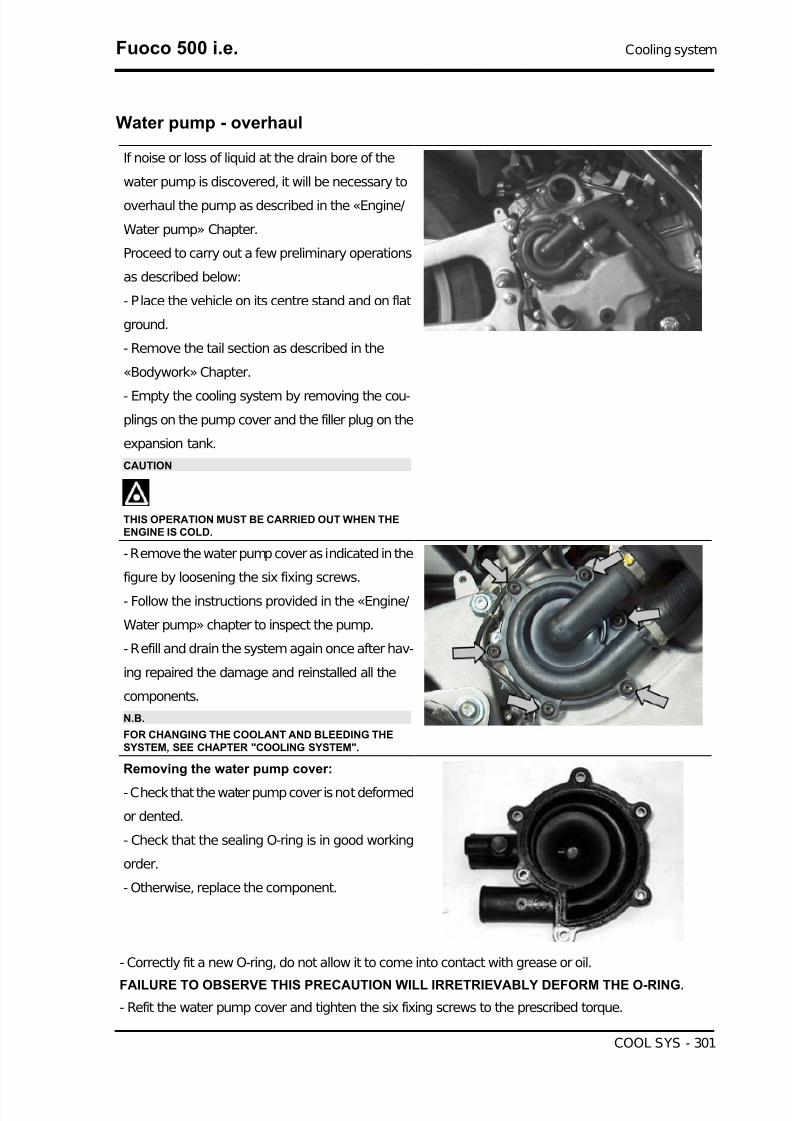
7/29/2019 Gilera Fuoco 500 i.e. (EN)
http://slidepdf.com/reader/full/gilera-fuoco-500-ie-en 301/329
Water pump - overhaul
If noise or loss of liquid at the drain bore of the
water pump is discovered, it will be necessary to
overhaul the pump as described in the «Engine/
Water pump» Chapter.
Proceed to carry out a few preliminary operations
as described below:
- Place the vehicle on its centre stand and on flat
ground.
- Remove the tail section as described in the
«Bodywork» Chapter.
- Empty the cooling system by removing the cou-
plings on the pump cover and the filler plug on the
expansion tank.
CAUTION
THIS OPERATION MUST BE CARRIED OUT WHEN THEENGINE IS COLD.
- Remove the water pump cover as indicated in the
figure by loosening the six fixing screws.
- Follow the instructions provided in the «Engine/
Water pump» chapter to inspect the pump.
- Refill and drain the system again once after hav-
ing repaired the damage and reinstalled all the
components.
N.B.
FOR CHANGING THE COOLANT AND BLEEDING THESYSTEM, SEE CHAPTER "COOLING SYSTEM".
Removing the water pump cover:
- Check that the water pump cover is not deformed
or dented.
- Check that the sealing O-ring is in good working
order.
- Otherwise, replace the component.
- Correctly fit a new O-ring, do not allow it to come into contact with grease or oil.
FAILURE TO OBSERVE THIS PRECAUTION WILL IRRETRIEVABLY DEFORM THE O-RING.
- Refit the water pump cover and tighten the six fixing screws to the prescribed torque.
Fuoco 500 i.e. Cooling system
COOL SYS - 301

7/29/2019 Gilera Fuoco 500 i.e. (EN)
http://slidepdf.com/reader/full/gilera-fuoco-500-ie-en 302/329
Locking torques (N*m)
Water pump cover screws 3 ÷ 4
diagnosis
Excessive system pressure
1 - Check the expansion tank cap efficiency.
N.B.
THE CAP IS EQUIPPED WITH A PRESSURE-RELIEF VALVE CALIBRATED AT 0.9 BAR.
There is also a valve that must allow air inlet during the cooling step.
YES go to 2 NO go to 3
2 - Check the head gasket seal (see «Thermal group and timing system» chapter)
3 - Replace the cap.
Cooling fluid consumption
1 - Check the system outer seals as described above.
YES go to 2 NO go to 3
2 - Check the head gasket seal (see «Thermal group and timing system» chapter)
- If water leaks are detected in the engine oil, inspect the pad on the head cooling circuit.
3 - Fix any damaged seals.
Oil in the fluid
1 - Presence of oil in the coolant.
YES go to 2
2 - Check the head gasket seal (see «Thermal group and timing system» chapter)
Cooling system Fuoco 500 i.e.
COOL SYS - 302
7/29/2019 Gilera Fuoco 500 i.e. (EN)
http://slidepdf.com/reader/full/gilera-fuoco-500-ie-en 303/329
INDEX OF TOPICS
CHASSIS CHAS

7/29/2019 Gilera Fuoco 500 i.e. (EN)
http://slidepdf.com/reader/full/gilera-fuoco-500-ie-en 304/329
This section è is dedicated to the operations that can be carried out on the vehicle's bodywork.
Seat
- Raise the saddle.
- Undo the screw shown in the figure, remove the
cover and disconnect the rider presence sensor
connector.
- Remove the three fixing screws shown in the fig-
ure.
Instrument panel
- Remove the front handlebar cover.
- Remove the legshield.
- Remove the shield back plate upper side.
- Unscrew the six fixing screws and remove the
instrument panel.
Chassis Fuoco 500 i.e.
CHAS - 304

7/29/2019 Gilera Fuoco 500 i.e. (EN)
http://slidepdf.com/reader/full/gilera-fuoco-500-ie-en 305/329
Front handlebar cover
- Unscrew the six screws and remove the upper
cap and the rear handlebar cover.
- Unscrew the two screws fixing the handlebar to
remove the front part of the handlebar cover.
Headlight assy.
- Remove the front shield.
- Unscrew the screw of the tail light support.
- Disconnect the electrical terminals and remove
the support.
Fuoco 500 i.e. Chassis
CHAS - 305

7/29/2019 Gilera Fuoco 500 i.e. (EN)
http://slidepdf.com/reader/full/gilera-fuoco-500-ie-en 306/329
- Undo the two screws fixing it to the frame.
- Undo the two screws fixing it to the upper part of
the shield back plate.
- Disconnect the assembly connectors at both
sides and remove the support.
- Undo the ten screws fixing it to the support and
remove the headlight assemblies.
Chassis Fuoco 500 i.e.
CHAS - 306

7/29/2019 Gilera Fuoco 500 i.e. (EN)
http://slidepdf.com/reader/full/gilera-fuoco-500-ie-en 307/329
Frame central cover
- Unscrew the fuel tank cap.
- Remove the saddle.
- Remove the side fairings
Working from both sides:
- Undo the screw indicated and remove the cap lid.
- Undo the two screws.
- Undo the screw connecting it to the helmet com-
partment.
- Lift it so that the refuelling compartment opening
cable can be released.
- Remove the central frame cover.
Fuoco 500 i.e. Chassis
CHAS - 307

7/29/2019 Gilera Fuoco 500 i.e. (EN)
http://slidepdf.com/reader/full/gilera-fuoco-500-ie-en 308/329
Legshield
- Remove the spoiler.
- Unscrew the four screws indicated and remove
the lower part from the headlight assembly sup-
port.
Working from both sides, remove the lateral sec-
tions of the front shield:
- Undo the two screws fixing it to the shield back
plate, in the wheel housing, and to the upper part
of the shield back plate.
- Unscrew the three screws indicated, release the
cover from it fittings and remove it.
Chassis Fuoco 500 i.e.
CHAS - 308
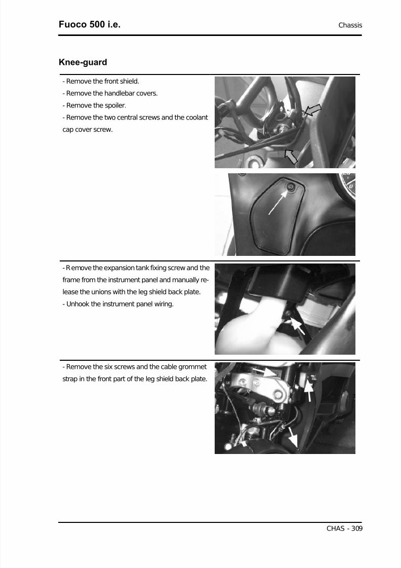
7/29/2019 Gilera Fuoco 500 i.e. (EN)
http://slidepdf.com/reader/full/gilera-fuoco-500-ie-en 309/329
Knee-guard
- Remove the front shield.
- Remove the handlebar covers.
- Remove the spoiler.
- Remove the two central screws and the coolant
cap cover screw.
- Remove the expansion tank fixing screw and the
frame from the instrument panel and manually re-
lease the unions with the leg shield back plate.
- Unhook the instrument panel wiring.
- Remove the six screws and the cable grommet
strap in the front part of the leg shield back plate.
Fuoco 500 i.e. Chassis
CHAS - 309

7/29/2019 Gilera Fuoco 500 i.e. (EN)
http://slidepdf.com/reader/full/gilera-fuoco-500-ie-en 310/329
- Remove the ignition switch plastic ring and the
two plastic covers near the footrest.
- Remove the five screws on the leg shield back
plate rear part.
- Remove the two leg shield back plate front
screws, see figure.
Chassis Fuoco 500 i.e.
CHAS - 310
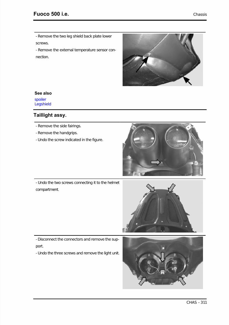
7/29/2019 Gilera Fuoco 500 i.e. (EN)
http://slidepdf.com/reader/full/gilera-fuoco-500-ie-en 311/329
- Remove the two leg shield back plate lower
screws.
- Remove the external temperature sensor con-
nection.
See also
spoilerLegshield
Taillight assy.
- Remove the side fairings.
- Remove the handgrips.
- Undo the screw indicated in the figure.
- Undo the two screws connecting it to the helmet
compartment.
- Disconnect the connectors and remove the sup-
port.
- Undo the three screws and remove the light unit.
Fuoco 500 i.e. Chassis
CHAS - 311

7/29/2019 Gilera Fuoco 500 i.e. (EN)
http://slidepdf.com/reader/full/gilera-fuoco-500-ie-en 312/329
Footrest
Remove the central cover.
Remove the four screws and extract the half-foot-
rest.
Follow the same procedure for both half-footrests.
Release the fuse-box
See also
Frame central cover
Side fairings
- These operations are described once but apply
to both side fairings.
- Undo the three screws on the handgrip cover.
- Undo the seven fixing screws.
- Remove the side fairing by pulling it in order to release the hooks.
Chassis Fuoco 500 i.e.
CHAS - 312

7/29/2019 Gilera Fuoco 500 i.e. (EN)
http://slidepdf.com/reader/full/gilera-fuoco-500-ie-en 313/329
License plate holder
- Undo the two upper screws fixing it to the rear
plastic element and the three screws fixing it to the
frame.
Helmet bay
- Remove the side fairings.
- Remove the side handgrips.
- Remove the central frame cover.
- Undo the two screws on the battery compart-
ment, detach the fuse terminal block, the battery
wires and the connector to the diagnostics socket.
- Disconnect the connectors of the power socket
and the helmet compartment light.
- Undo the screws fixing the helmet compartment
light switch to the compartment and disconnect the
electrical terminals.
Fuoco 500 i.e. Chassis
CHAS - 313

7/29/2019 Gilera Fuoco 500 i.e. (EN)
http://slidepdf.com/reader/full/gilera-fuoco-500-ie-en 314/329
- Undo the screws fixing the voltage regulator to
the helmet compartment internal side.
- Undo the two screws of the saddle lock, discon-
nect the lock cables and release the sheath from
the helmet compartment.
- Undo the four screws below the gaskets in the
upper part of the compartment.
- Undo the three screws fixing it to the frame on
both sides.
Chassis Fuoco 500 i.e.
CHAS - 314

7/29/2019 Gilera Fuoco 500 i.e. (EN)
http://slidepdf.com/reader/full/gilera-fuoco-500-ie-en 315/329
- Remove the helmet compartment.
spoiler
- Remove the GILERA clip-on badge paying at-
tention not to spoil the paint.
- Undo the screw underneath.
- Undo the four screws indicated.
Fuel tank
Remove the chassis central cover.
Remove the footrest.
Remove the three tank retainers.
Fuoco 500 i.e. Chassis
CHAS - 315

7/29/2019 Gilera Fuoco 500 i.e. (EN)
http://slidepdf.com/reader/full/gilera-fuoco-500-ie-en 316/329
Remove the two lower bracket retainers indicated
in the figure.
Disconnect the electric wiring and the fuel pipes.
See also
Footrest
Rear
Remove the four fixing screws of the cover and
release it from the two leverages.
Chassis Fuoco 500 i.e.
CHAS - 316

7/29/2019 Gilera Fuoco 500 i.e. (EN)
http://slidepdf.com/reader/full/gilera-fuoco-500-ie-en 317/329
Handles and top side fairings
- Remove the side fairings.
- Undo the seven screws fixing the turn indicator
arrows.
- Disconnect the license plate light connector.
- Undo the three screws indicated at both sides
and remove the handgrip clamp.
Radiator cover
- Remove the front shield.
- Remove the headlight assembly.
- Disconnect the turn indicators wirings.
- Undo the two screws indicated.
Fuoco 500 i.e. Chassis
CHAS - 317

7/29/2019 Gilera Fuoco 500 i.e. (EN)
http://slidepdf.com/reader/full/gilera-fuoco-500-ie-en 318/329
- Undo the two screws indicated.
- Undo the two screws of the supporting clamp.
- Remove the supporting clamp.
- Remove the two protective screws that fix the ra-
diator lower protection to the shield back plate.
After that, press up and pull the protection front
part so as to release it from the radiator frame.
Chassis Fuoco 500 i.e.
CHAS - 318

7/29/2019 Gilera Fuoco 500 i.e. (EN)
http://slidepdf.com/reader/full/gilera-fuoco-500-ie-en 319/329
Battery
- Raise the saddle.
- Undo the two screws of the battery cover.
Lower cover
Montaggio
- Dalle viti di corredo prendere: tre viti con rondelle,
tre piastrine elastiche e tre distanziali.
- Inserire i distanziali nei tre fori indicati.
Fuoco 500 i.e. Chassis
CHAS - 319

7/29/2019 Gilera Fuoco 500 i.e. (EN)
http://slidepdf.com/reader/full/gilera-fuoco-500-ie-en 320/329
- Inserire dove indicato le tre piastrine elastiche.
- Montare il paracolpi inferiore, avvitando le tre viti
complete di rondelle.
Smontaggio
- Svitare le tre viti complete di rondelle di fissaggio
al telaio, e recuperare il distanziale.
Chassis Fuoco 500 i.e.
CHAS - 320

7/29/2019 Gilera Fuoco 500 i.e. (EN)
http://slidepdf.com/reader/full/gilera-fuoco-500-ie-en 321/329
Fuoco 500 i.e. Chassis
CHAS - 321

7/29/2019 Gilera Fuoco 500 i.e. (EN)
http://slidepdf.com/reader/full/gilera-fuoco-500-ie-en 322/329
INDEX OF TOPICS
PRE-DELIVERY PRE DE

7/29/2019 Gilera Fuoco 500 i.e. (EN)
http://slidepdf.com/reader/full/gilera-fuoco-500-ie-en 323/329
Carry out the listed tests before delivering the vehicle.
Warning - Handle fuel with care.
Fit the plastic cover supplied on the joint on the
steering tube as shown in the figure.
Proceed as follows if the customer requests in-
stallation of splash guards on the vehicle:
• Fit the flap inside the mudguard shown
in the figure, matching up the 4 anchor
holes.
• Fit the 4 washers and the 4 screws on
the outer side of the mudguard, then
tighten to the specified torque.
Locking torques (N*m)
splash guard fastener screws 2 - 3
Aesthetic inspection
Appearance check:
- Paintwork
- Fitting of plastics
- Scratches
- Dirt
Tightening torques inspection
Lock check
- Safety fasteners
- Fixing screws
Safety fasteners:
• Rear shock absorber upper fixing
•
Rear shock absorber lower fixing• Front shock absorber upper fixing
Fuoco 500 i.e. Pre-delivery
PRE DE - 323
7/29/2019 Gilera Fuoco 500 i.e. (EN)
http://slidepdf.com/reader/full/gilera-fuoco-500-ie-en 324/329
• Front shock absorber lower fixing
• Sliding stems fixing
• Break callipers fixing
• Front wheels fixing screws• Front wheels axle nut
• Rear wheel axle nut
• Chassis - engine swinging arm fixing
• Handlebar lock nut
• Lower ring nut for side steering tubes
• Upper ring nut for side steering tubes
• Lower ring nut for central steering tube
•
Upper ring nut for central steering tubes• Constant-velocity universal joints
Electrical system
• Battery
• Main switch
• Lights: high beam lights, low beam lights, taillights (front and rear) and relevant warning lights
- Headlight adjustment according to the regulations currently in force
• Front and rear stop light buttons and bulb• Turn indicators and their warning lights
• Instrument lighting
• instruments: fuel and temperature indicator
•Instrument panel lights
• Horn
• Electric starter
• Engine stopping with emergency stop switch
• Electric opening of saddle with solenoid
• Tilting system locking - unlocking button
CAUTION
TO ENSURE MAXIMUM PERFORMANCE, THE BATTERY MUST BE CHARGED BEFORE USE.INADEQUATE CHARGING OF THE BATTERY WITH A LOW LEVEL OF ELECTROLYTE BEFOREIT IS FIRST USED SHORTENS THE LIFE OF THE BATTERY.
CAUTION
WHEN INSTALLING THE BATTERY, ATTACH THE POSITIVE LEAD FIRST AND THEN THE NEG-ATIVE ONE.
WARNING
BATTERY ELECTROLYTE IS TOXIC AND IT MAY CAUSE SERIOUS BURNS. IT CONTAINS SUL-
PHURIC ACID. AVOID CONTACT WITH YOUR EYES, SKIN AND CLOTHING.IN CASE OF CONTACT WITH YOUR EYES OR SKIN, RINSE WITH ABUNDANT WATER FORABOUT 15 MINUTES AND SEEK IMMEDIATE MEDICAL ATTENTION.
Pre-delivery Fuoco 500 i.e.
PRE DE - 324

7/29/2019 Gilera Fuoco 500 i.e. (EN)
http://slidepdf.com/reader/full/gilera-fuoco-500-ie-en 325/329
IF IT ACCIDENTALLY SWALLOWED, IMMEDIATELY DRINK LARGE QUANTITIES OF WATER ORVEGETABLE OIL. SEEK IMMEDIATE MEDICAL ATTENTION.BATTERIES PRODUCE EXPLOSIVE GASES; KEEP THEM AWAY FROM NAKED FLAMES,SPARKS AND CIGARETTES. IF THE BATTERY IS CHARGED IN A CLOSED PLACE, TAKE CARETO ENSURE ADEQUATE VENTILATION. ALWAYS PROTECT YOUR EYES WHEN WORKING
CLOSE TO BATTERIES.KEEP OUT OF THE REACH OF CHILDREN
CAUTION
NEVER USE FUSES WITH A CAPACITY HIGHER THAN THAT RECOMMENDED. USING A FUSEOF UNSUITABLE RATING MAY SERIOUSLY DAMAGE THE VEHICLE OR EVEN CAUSE A FIRE.
Levels check
Level check:
- Hydraulic brake system liquid level.
- Roll lock system fluid level- Rear hub oil level
- Engine coolant level
- Engine oil level
Road test
Test ride
- Cold start
- Instrument operations
- Response to the gas command
- Stability on acceleration and braking
- Rear and front brake efficiency
- Parking brake efficiency
- Rear and front suspension efficiency
- Abnormal noise
- Tilting system locking - unlocking efficiency
Static test
Static control after the test ride:
• Hot engine restart
• Minimum seal (turning the handlebar)
• Uniform steering rotation
• Possible losses
• electric radiator fan operation
CAUTIONCHECK AND ADJUST TYRE PRESSURE WITH TYRES AT AMBIENT TEMPERATURE.
CAUTION
Fuoco 500 i.e. Pre-delivery
PRE DE - 325

7/29/2019 Gilera Fuoco 500 i.e. (EN)
http://slidepdf.com/reader/full/gilera-fuoco-500-ie-en 326/329
NEVER EXCEED THE RECOMMENDED INFLATION PRESSURES OR TYRES MAY BURST.
Functional inspection
Verifica Funzionale:• Impianto frenante idraulico: corsa della leva
• Frizione: verifica corretto funzionamento
• Motore: verifica corretto funzionamento generale e assenza di rumorosità anomale
• Altro: verifica documenti, verifica n° di telaio e n° di motore, attrezzi a corredo, montaggio targa,
controllo serrature, controllo pressione pneumatici, montaggio specchietti, montaggio paracolpi inferi-
ore ed eventuali accessori
Pre-delivery Fuoco 500 i.e.
PRE DE - 326

7/29/2019 Gilera Fuoco 500 i.e. (EN)
http://slidepdf.com/reader/full/gilera-fuoco-500-ie-en 327/329
INDEX OF TOPICS
TIME TIME

7/29/2019 Gilera Fuoco 500 i.e. (EN)
http://slidepdf.com/reader/full/gilera-fuoco-500-ie-en 328/329
Flywheel cover
FLYWHEEL COVERCode Action Duration
1 001087 Flywheel cover - Replacement2 001113 Water pump - Replacement3 001123 Oil filter -Replacement4 001124 By-pass valve - Replacement5 001150 Flywheel cover gasket - change6 001160 Minimum oil pressure sensor - Re-
placement7 001102 Net oil filter - change / Cleaning8 003064 Engine oil - change
Time Fuoco 500 i.e.
TIME - 328

7/29/2019 Gilera Fuoco 500 i.e. (EN)
http://slidepdf.com/reader/full/gilera-fuoco-500-ie-en 329/329
A
Air filter: 26
BBattery: 48, 58, 63, 319
Brake: 283, 285, 286, 288, 290–293
CChecks: 52
Coolant: 220, 299
EElectric: 297
Engine oil: 27
FFuel: 191, 199, 315
Fuses: 60
HHeadlight: 32, 305
Hub oil: 25
IIdentification: 8
Instrument panel: 304
MMaintenance: 7, 21
OOil filter: 29
RRecommended products:
SShock absorbers: 280
Spark plug: 24, 217
Start-up:
Suspension:36, 37, 243
Switch:
T Tank:315