Generatore a Magneti Permanenti Permanent Magnet Generator · Generatore a Magneti Permanenti...
12
Generatore a Magneti Permanenti Permanent Magnet Generator MANUALE D'USO E MANUTENZIONE USE AND MAINTENANCE MANUAL NSM S.r.l. Via Lazio, 5/b 36015 Schio (Vicenza) - Italy tel: +39 0445 595888 fax: +39 0445 595800 www.nsmsrl.it [email protected] 201601 PMG-GS PMG-DC
Transcript of Generatore a Magneti Permanenti Permanent Magnet Generator · Generatore a Magneti Permanenti...
Generatore a Magneti Permanenti
Permanent Magnet Generator
MANUALE D'USO E MANUTENZIONE
USE AND MAINTENANCE MANUAL
NSM S.r.l.Via Lazio, 5/b36015 Schio (Vicenza) - Italy
tel: +39 0445 595888fax: +39 0445 595800
201601
PMG-GS
PMG-DC

ISTRUZIONI D’USO
ATTENZIONE!Le istruzioni fornite riportano informazioni atte ad essere utilizzate dapersonale tecnico qualificato; esse devono sempre essere integratedalle leggi e normative vigenti in materia.Le macchine elettriche rotanti presentano parti pericolose in quantoposte sotto tensione ed in rotazione. Pertanto un uso improprio, lacarenza di manutenzione, lo scollegamento dei dispositivi diprotezione possono essere causa di gravi danni a persone o cose.Il grado di protezione del generatore PMG dipende dalla tipologiacostruttiva: è compito del cliente adottare nel caso le misurenecessarie, nel rispetto delle normative vigenti in materia, per portareil gruppo assemblato al grado di protezione desiderato
VERIFICHE PRELIMINARIAl momento del ricevimento si raccomanda di esaminare l`alternatoreper controllare che non abbia subito danni durante il trasporto.
IMMAGAZZINAGGIONel caso l`alternatore non venisse posto immediatamente in serviziodovrà essere immagazzinato in luogo coperto, pulito e privod`umidità.Prima della messa in servizio dopo lunghi periodi di inattività éconsigliabile verificare la resistenza di isolamento di tutti gliavvolgimenti e verso massa: scollegare tutti i dispositivi elettronicieventualmente associati ed effettuare la misura: con macchina atemperatura ambiente si devono ottenere valori maggiori di 2MOhm.Se così non fosse si rende necessario procedere all`essicazione inforno (a circa 60º-80ºC)
ACCOPPIAMENTO MECCANICOFar riferimento alle istruzioni a seguire.
COLLEGAMENTO ELETTRICO
INSTALLAZIONE
Assemblare il gruppo nel rispetto delle indicazioni riportate nel seguitodel presente manuale
MANUTENZIONEL`alternatore e gli eventuali accessori devono essere sempre tenutipuliti.Verificare periodicamente che il gruppo funzioni senza vibrazioni orumori anomali e che le aperture di aspirazione/esplusione aria (sepresenti) non siano ostruite
Nel caso di realizzazione di cofanatura protettiva del gruppoassemblato studiare accuratamente il flusso del circuito diventilazione al fine di garantire un adeguato raffreddamentoNel caso di optional aggiuntivi (esempio: attuatore) far riferimento allerelative istruzioni specifiche fornite
Accertarsi che il carico destinato a essere alimentato dal generatoresia compatibile con i suoi dati di targa.Eseguire i collegamenti come da schema elettrico a seguire.Nel caso di optional aggiuntivi (esempio: Inverter, convertitoreAC/DC)far riferimento alle relative istruzioni specifiche fornitePrima di applicare il carico effettuare una prova di funzionamento avuoto e misurare le tensioni in uscita, verificando che questecorrispondano a quanto previsto
Installare il gruppo in un locale ben ventilato. Fare attenzione a che leaperture di aspirazione ed espulsione dell`aria di raffreddamentosiano libere. L'alternatore deve aspirare aria pulita: è importanteevitare l'aspirazione dell'aria calda espulsa dall'alternatore stesso e/odal motore primo, nonché i gas di scarico del motore, polveri esporcizia varia.
Attenzione!: Evitare di far funzionare il gruppo ad un nr° di giridiversi da quello nominale
Dati tecnici non impegnativi: NSM si riserva il diritto di apportaremodifiche senza l’obbligo di darne preventiva comunicazione
INSTRUCTIONS
WARNING!The operating instructions include only the directions to be followed bythe qualified personnel; they must always be supplemented by therelevant legal provisions and standards.Electric rotating machines have dangerous parts: they have live androtating components. Therefore: improper use, inadequate inspectionand maintenance and the removal of protective covers and thedisconnection of protection devices can cause severe personal injuryor property damage.PMG IP protection degree depends on its product type:
PRELIMINARY CHECKSOn receipt it is recommended to inspect the alternator to find outwhether it has got damages during transportation.
STORAGEIf the alternator is not installed immediately, it should be kept indoor, ina clean and dry place.Before starting up the alternator after long periods of inactivity orstorage, the winding insulation resistance must to be measured.Disconnect al electronic devices connected to the PMG and check thevalues: those should be higher than 2MOhm at room temperature. Ifthis value cannot be obtained it is necessary to reset the insulation,drying the windings (using an oven at 60º-80º C).
MECHANICALCOUPLINGRefer to the following assembling instructions.
ELECTRIC CONNECTION
INSTALLATION
Assembly the unit complying with precautions reported in this manualon following pages
MAINTENANCEThe alternator as well as the possible accessories should always bekept clean.It is recommended to periodically check that the unit operates withoutanomalous vibrations or noises, and that the air inlet/outlet apertures(if any) are not obstructed
the customerhimself has to take all the necessary expedients, respecting therelevant provisions and standards, to classify the generator set at thedesired protection class
In case you are going to use a protective cover, you must studycarefully the ventilation flow, in order to obtain an adequate coolingIn case of additional optionals (example: actuator) please refer to therelated instructions provided
Make sure that the load intended to be powered is suitable with thegenerator data label.Make the electric connections as indicated in the wiring diagram thatfollows.In case of additional optionals (example: Inverter, AC/DC converter)please refer to the related instructions providedBefore powering the load make a test in no load voltage condition, andmeasure output voltages, checking they match the expected values
Set up the unit in a well-cooled place.Make sure that cooling air intake and discharge openings are free andunblocked.The alternator must suck in clean air only: the suction of the hot airexpelled from the alternator itself and/or the prime motor must beavoided, as well as the suction of motor exhaust fumes, dust and dirt.
Warning!: do not operate the unit at a different rpm than thenominal one
Technical data not binding: NSM reserves the right to modify thecontents without prior notice
ISTRUZIONI PER IL MONTAGGIO
PMG-R forma B3/B9
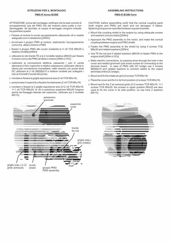
ATTENZIONE: prima del montaggio verificare che le sedi coniche diaccoppiamento (sia del PMG che del motore) siano pulite e nondanneggiate. Se riportate, le coppie di serraggio vengono indicatetra parentesi quadre
Fissare al motore lo scudo accoppiamento utilizzando viti e rosetteadeguate (non in dotazione) [25Nm]
montare e fissare la griglia aspirazione aria (4 viti TCR M5x16)
1+1 viti TCR M5x20
>
>
>
Avvicinare il gruppo PMG al motore, realizzando l’accoppiamentoconico tra albero motore e PMG
fissare il gruppo PMG allo scudo mediante le 4 viti TCE M8x30 erelative rondelle [25Nm]
utilizzare la vite tirante TE e le 2 rondelle relative (Ø8/24) per fissareil mozzo conico del PMG all’albero motore [30Nm ±10%]
realizzare la connessione elettrica, passando i cavi in uscitaattraverso il foro coperchio e relativo passacavo (utilizzare viteria inottone per connessione morsettiera; nelle versioni con ponte diodiDC utilizzare le 2 viti (M[5|6]x10 e relative rondelle per collegare icavi ai morsetti d’uscita del ponte)
posizionare il coperchio e fissarlo frontalmente (2 viti TCR M5x16)
montare e fissare le 2 griglie espulsione aria (2+2 viti TCR M5x16,: le viti in posizione superiore M5x20 fungono
anche da fissaggio laterale del coperchio, utilizzare qui 2 rondelleØ5/15)
>
>
>
>
>
ASSEMBLING INSTRUCTIONS
PMG-R B3/B9 form
CAUTION: before assembling verify that the conical coupling parts(both engine and PMG) are clean and not damaged. If stated,tightening torques are specified between square brackets
Mount the coupling shield to the engine by using adequate screwsand washers (not provided) [25Nm]
Approach the PMG assembly to the motor, and make the conicalcoupling between engine and PMG shafts
Fasten the PMG assembly to the shield by using 4 screws TCEM8x30 and related washers [25Nm]
Use TE tie-rod and 2 related washers (Ø8/24) to fasten PMG to theengine shaft [30Nm ±10%]
Make electric connections, by passing wires through the hole in thecover and related grommet (use brass screws for connecting to theterminal board; in case of PMG with DC bridge use 2 screwsM[5|6]x10 and related washers to connect cables to the outputterminals of the DC bridge) .
Mount and fix the intake air grid (4 screws TCR M5x16)
Place the cover and fix it in its front position (2 screws TCR M5x16)
Mount and fix the 2 air exhaust grids (2+2 screws TCR M5x16, 1+1screws TCR M5x20: the screws in upper position M5x20 are alsoused to fix the cover in its side position, so use here 2 washersØ5/15)
>
>
>
>
>
>
>
>
motoreengine
griglie (esp.) (x 2)grids (exhaust)
scudoshield gruppo PMG
PMG assembly
griglia (asp.)grid (intake)
coperchiocover
passacavogrommet
tirantetie-rod
M5x20
ISTRUZIONI PER IL MONTAGGIO
PMG-R forma SAE
ATTENZIONE: Se riportate, le coppie di serraggio vengono indicatetra parentesi quadre
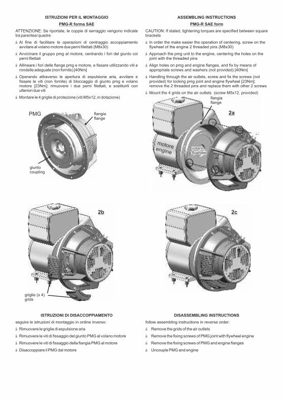
avvitare al volano motore due perni filettati (M8x30)>
>
>
>
>
Al fine di facilitare le operazioni di centraggio accoppiamento
Avvicinare il gruppo pmg al motore, centrando i fori del giunto coiperni filettati
Allineare i fori delle flange pmg e motore, e fissare utilizzando viti erondelle adeguate (non fornite) [40Nm]
Operando attraverso le apertura di espulsione aria, avvitare efissare le viti (non fornite) di bloccaggio di giunto pmg e volanomotore [23Nm]; rimuovere i due perni filettati, e sostituirli conulteriori due viti
Montare le 4 griglie di protezione (viti M5x12, in dotazione)
flangiaflange
giuntocoupling
motoreenginevolanoflywheel
flangiaflange
griglie (x 4)grids
ASSEMBLING INSTRUCTIONS
PMG-R SAE form
CAUTION: If stated, tightening torques are specified between squarebrackets
>
>
>
>
>
In order the make easier the operation of centering, screw on theflywheel of the engine 2 threaded pins (M8x30)
Approach the pmg unit to the engine, centering the holes on thejoint with the threaded pins
Align holes on pmg and engine flanges, and fix by means ofappropriate screws and washers (not provided) [40Nm]
Handling through the air outlets, screw and fix the screws (notprovided) for locking pmg joint and engine flywheel [23Nm];remove the 2 threaded pins and replace them with other 2 screws
Mount the 4 grids on the air outlets (screw M5x12, provided)
PMG
ISTRUZIONI DI DISACCOPPIAMENTO
seguire le istruzioni di montaggio in ordine inverso:
Rimuovere le griglie di espulsione aria
Rimuovere le viti di fissaggio del giunto PMG al volano motore
Rimuovere le viti di fissaggio della flangia PMG al motore
Disaccoppiare il PMG dal motore
>
>
>
>
DISASSEMBLING INSTRUCTIONS
follow assembling instructions in reverse order:
Remove the grids of the air outlets
Remove the fixing screws of PMG joint with flywheel engine
Remove the fixing screws of PMG and engine flanges
Uncouple PMG and engine
>
>
>
>
2a
2b 2c
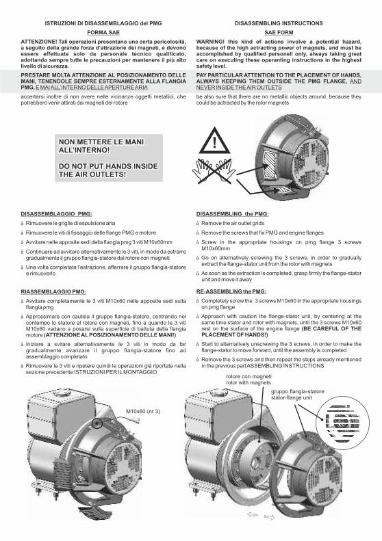
ISTRUZIONI DI DISASSEMBLAGGIO del PMG
ATTENZIONE! Tali operazioni presentano una certa pericolosità,a seguito della grande forza d’attrazione dei magneti, e devonoessere effettuate solo da personale tecnico qualificato,adottando sempre tutte le precauzioni per mantenere il più altolivello di sicurezza.
PRESTARE MOLTA ATTENZIONE AL POSIZIONAMENTO DELLEMANI, TENENDOLE SEMPRE ESTERNAMENTE ALLA FLANGIAPMG,
FORMA SAE
E MAIALL’INTERNO DELLEAPERTUREARIA
accertarsi inoltre di non avere nelle vicinanze oggetti metallici, chepotrebbero venir attirati dai magneti del rotore
DISASSEMBLING INSTRUCTIONS
WARNING! this kind of actions involve a potential hazard,because of the high actracting power of magnets, and must beaccomplished by qualified personell only, always taking greatcare on executing these operanting instructions in the highestsafety level.
PAY PARTICULAR ATTENTION TO THE PLACEMENT OF HANDS,ALWAYS KEEPING THEM OUTSIDE THE PMG FLANGE,
SAE FORM
ANDNEVER INSIDE THEAIR OUTLETS
be also sure that there are no metallic objects around, because theycould be actracted by the rotor magnets
NON METTERE LE MANIALL’INTERNO!
DO NOT PUT HANDS INSIDETHE AIR OUTLETS!
gruppo flangia-statorestator-flange unit
rotore con magnetirotor with magnets
M10x60 (nr 3)
DISASSEMBLAGGIO PMG:
RIASSEMBLAGGIO PMG:
>
>
>
>
>
>
>
>
>
Rimuovere le griglie di espulsione aria
Rimuovere le viti di fissaggio delle flange PMG e motore
Avvitare nelle apposite sedi della flangia pmg 3 viti M10x60mm
Continuare ad avvitare alternativamente le 3 viti, in modo da estrarregradualmente il gruppo flangia-statore dal rotore con magneti
Una volta completata l’estrazione, afferrare il gruppo flangia-statoree rimuoverlo
Avvitare completamente le 3 viti M10x60 nelle apposite sedi sullaflangia pmg
Approssimare con cautela il gruppo flangia-statore, centrando nelcontempo lo statore al rotore con magneti, fino a quando le 3 vitiM10x60 vadano a posarsi sulla superficie di battuta della flangiamotore
Iniziare a svitare alternativamente le 3 viti in modo da fargradualmente avanzare il gruppo flangia-statore fino adassemblaggio completato
Rimuovere le 3 viti e ripetere quindi le operazioni già riportate nellasezione precedente ISTRUZIONI PER ILMONTAGGIO
(ATTENZIONEAL POSIZIONAMENTO DELLE MANI!)
DISASSEMBLING the PMG:
RE-ASSEMBLING the PMG:
>
>
>
>
>
>
>
>
>
Remove the air outlet grids
Remove the screws that fix PMG and engine flanges
Screw in the appropriate housings on pmg flange 3 screwsM10x60mm
Go on alternatively screwing the 3 screws, in order to graduallyextract the flange-stator unit from the rotor with magnets
As soon as the extraction is completed, grasp firmly the flange-statorunit and move it away
Completely screw the 3 screws M10x60 in the appropriate housingson pmg flange
Approach with caution the flange-stator unit, by centering at thesame time stator and rotor with magnets, until the 3 screws M10x60rest on the surface of the engine flange
Start to alternatively unscrewing the 3 screws, in order to make theflange-stator to move forward, until the assembly is completed
Remove the 3 screws and then repeat the steps already mentionedin the previous partASSEMBLING INSTRUCTIONS
(BE CAREFUL OF THEPLACEMENT OF HANDS!)
V 3ph
Resistenze avvolgimentiWinding resistances
carica batterie (opt)battery charger
statorestator
12V - 10A dc
gre
y
gre
y
bla
ck
red
B.C.controller
INVERTER
output
V 1ph
attuatore - actuator
(optional)
PMGE
actuator
inverter V 1~
PMG-GS
FILTER
bro
wn
white
bla
ck
ferrite(2 spire/turns)
ferrite(3 spire/turns)
ferrite(2 spire/turns)
blue
brown
yellow/green
morsettieraterminal board(SAE)
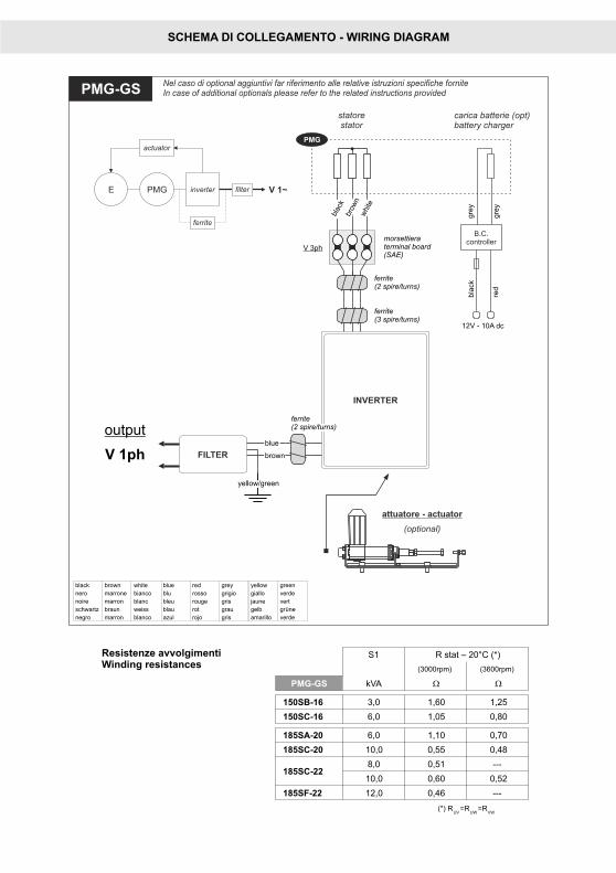
Nel caso di optional aggiuntivi far riferimento alle relative istruzioni specifiche forniteIn case of additional optionals please refer to the related instructions provided
filter
PMG
ferrite
black brown white blue red grey yellow green
nero marrone bianco blu rosso grigio giallo verde
noire marron blanc bleu rouge gris jaune vert
schwartz braun weiss blau rot grau gelb
negro marron blanco azul rojo gris amarillo verde
grüne
SCHEMA DI COLLEGAMENTO - WIRING DIAGRAM
S1 R stat – 20°C (*)
(3000rpm) (3600rpm)
PMG-GS kVA W W
150SB-16 3,0 1,60 1,25
150SC-16 6,0 1,05 0,80
185SA-20 6,0 1,10 0,70
185SC-20 10,0 0,55 0,48
185SC-228,0 0,51 ---
10,0 0,60 0,52
185SF-22 12,0 0,46 ---
(*) RUV
=RUW
=RVW
attuatore - actuator
(optional)
yello
w
yello
w
white
red
bla
ck
red
white
bla
ck
AC1
AC2
AC3
V 3ph
PMGE
actuator
AC/DCconv.
Vdc
AC/DCCONVERTER
AC1AC3
AC2
ACTU
ATOR -
J13
AUX -
J8
statorestator
ausiliarioauxiliary
AUX
PMG-DC
J13
output
Vdc
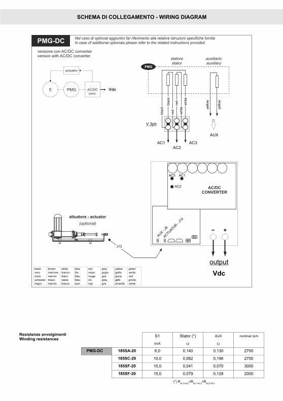
Nel caso di optional aggiuntivi far riferimento alle relative istruzioni specifiche forniteIn case of additional optionals please refer to the related instructions provided
PMG
black brown white blue red grey yellow green
nero marrone bianco blu rosso grigio giallo verde
noire marron blanc bleu rouge gris jaune vert
schwartz braun weiss blau rot grau gelb
negro marron blanco azul rojo gris amarillo verde
grüne
S1 Stator (*) AUX nominal rpm
kVA W W
PMG-DC 185SA-20 6,0 0,140 0,130 2700
185SC-20 10,0 0,082 0,196 2700
185SF-20 15,0 0,041 0,070 3000
185SF-20 15,0 0,079 0,128 2000
(*) RAC1-AC2
=RAC1-AC3
=RAC2-AC3
versione con AC/DC converterversion with AC/DC converter
SCHEMA DI COLLEGAMENTO - WIRING DIAGRAM
Resistenze avvolgimentiWinding resistances
V 3ph(stator)
V 3ph(stator)V out
(Idc)
SCHEMA DI COLLEGAMENTO - WIRING DIAGRAM
Resistenze avvolgimentiWinding resistances
PMGE Vdc
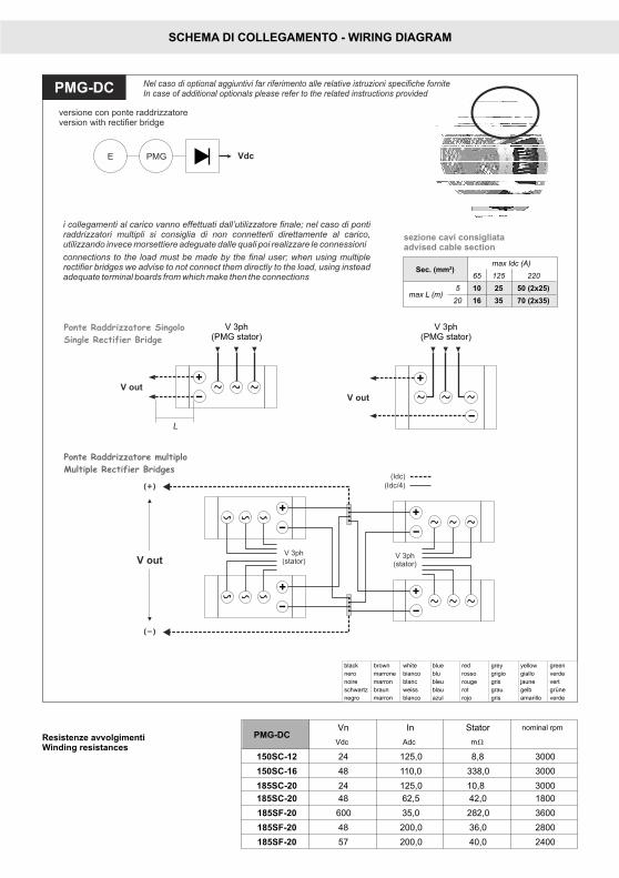
PMG-DC Nel caso di optional aggiuntivi far riferimento alle relative istruzioni specifiche forniteIn case of additional optionals please refer to the related instructions provided
black brown white blue red grey yellow green
nero marrone bianco blu rosso grigio giallo verde
noire marron blanc bleu rouge gris jaune vert
schwartz braun weiss blau rot grau gelb
negro marron blanco azul rojo gris amarillo verde
grüne
V out
V 3ph(PMG stator)
V 3ph(PMG stator)
Ponte Raddrizzatore Singolo
Single Rectifier Bridge
Ponte Raddrizzatore multiplo
Multiple Rectifier Bridges
i collegamenti al carico vanno effettuati dall’utilizzatore finale; nel caso di pontiraddrizzatori multipli si consiglia di non connetterli direttamente al carico,utilizzando invece morsettiere adeguate dalle quali poi realizzare le connessioni
connections to the load must be made by the final user; when using multiplerectifier bridges we advise to not connect them directly to the load, using insteadadequate terminal boards from which make then the connections
V out
L
Sec. (mm²)max Idc (A)
65 125 220
max L (m)5 10 25 50 (2x25)
20 16 35 70 (2x35)
versione con ponte raddrizzatoreversion with rectifier bridge
sezione cavi consigliataadvised cable section
(Idc/4)
PMG-DCVn In Stator nominal rpm
Vdc Adc
150SC-12 24 125,0 8,8 3000
150SC-16 48 110,0 338,0 3000
185SC-20 48 62,5 42,0 1800
185SF-20 600 35,0 282,0 3600
185SF-20 48 200,0 36,0 2800
185SF-20 57 200,0 40,0 2400
mW
185SC-20 24 125,0 10,8 3000
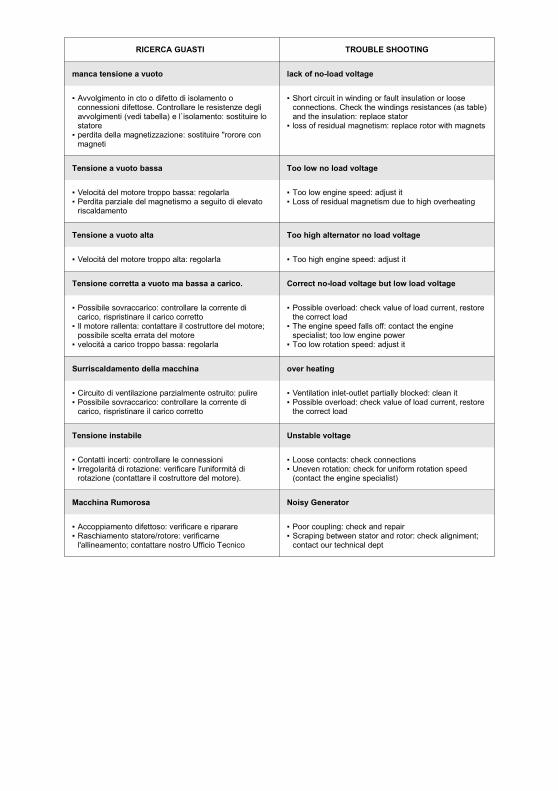
RICERCA GUASTI TROUBLE SHOOTING
manca tensione a vuoto lack of no-load voltage
▪ Avvolgimento in cto o difetto di isolamento oconnessioni difettose. Controllare le resistenze degliavvolgimenti (vedi tabella) e l`isolamento: sostituire lostatore
▪ perdita della magnetizzazione: sostituire "rorore conmagneti
▪ Short circuit in winding or fault insulation or looseconnections. Check the windings resistances (as table)and the insulation: replace stator
▪ loss of residual magnetism: replace rotor with magnets
Tensione a vuoto bassa Too low no load voltage
▪ Velocitá del motore troppo bassa: regolarla▪ Perdita parziale del magnetismo a seguito di elevato
riscaldamento
▪ Too low engine speed: adjust it▪ Loss of residual magnetism due to high overheating
Tensione a vuoto alta Too high alternator no load voltage
▪ Velocitá del motore troppo alta: regolarla ▪ Too high engine speed: adjust it
Tensione corretta a vuoto ma bassa a carico. Correct no-load voltage but low load voltage
▪ Possibile sovraccarico: controllare la corrente dicarico, rispristinare il carico corretto
▪ Il motore rallenta: contattare il costruttore del motore;possibile scelta errata del motore
▪ velocità a carico troppo bassa: regolarla
▪ Possible overload: check value of load current, restorethe correct load
▪ The engine speed falls off: contact the enginespecialist; too low engine power
▪ Too low rotation speed: adjust it
Surriscaldamento della macchina over heating
▪ Circuito di ventilazione parzialmente ostruito: pulire▪ Possibile sovraccarico: controllare la corrente di
carico, rispristinare il carico corretto
▪ Ventilation inlet-outlet partially blocked: clean it▪ Possible overload: check value of load current, restore
the correct load
Tensione instabile Unstable voltage
▪ Contatti incerti: controllare le connessioni▪ Irregolaritá di rotazione: verificare l'uniformitá di
rotazione (contattare il costruttore del motore).
▪ Loose contacts: check connections▪ Uneven rotation: check for uniform rotation speed
(contact the engine specialist)
Macchina Rumorosa Noisy Generator
▪ Accoppiamento difettoso: verificare e riparare▪ Raschiamento statore/rotore: verificarne
l'allineamento; contattare nostro Ufficio Tecnico
▪ Poor coupling: check and repair▪ Scraping between stator and rotor: check aligniment;
contact our technical dept
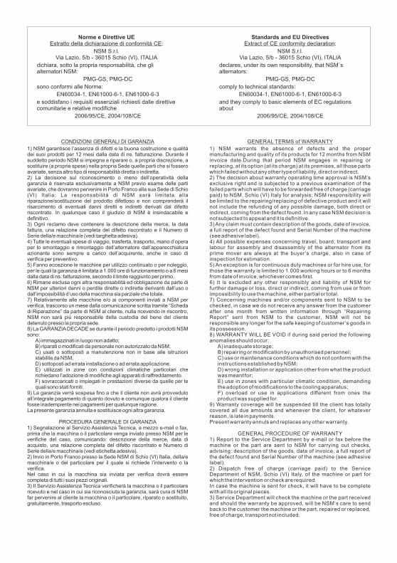
CONDIZIONI GENERALI DI GARANZIA
1) NSM garantisce l’assenza di difetti e la buona costruzione e qualitàdei suoi prodotti per 12 mesi dalla data di ns. fatturazione. Durante ilsuddetto periodo NSM si impegna a riparare o, a propria discrezione, asostituire (a proprie spese) nella propria Sede quelle parti che si fosseroavariate, senza altro tipo di responsabilità diretta o indiretta.2) La decisione sul riconoscimento o meno dell’operatività dellagaranzia è riservata esclusivamente a NSM previo esame delle partiavariate, che dovranno pervenire in Porto Franco alla sua Sede di Schio(VI) Italia; La responsabilità di NSM sarà limitata allariparazione/sostituzione del prodotto difettoso e non comprenderà ilrisarcimento di eventuali danni diretti e indiretti derivati dal difettoriscontrato. In qualunque caso il giudizio di NSM è insindacabile edefinitivo.3) Ogni reclamo deve contenere la descrizione della merce, la datafattura, una relazione completa del difetto riscontrato e il Numero diSerie della/e macchina/e (vedi targhetta adesiva).4) Tutte le eventuali spese di viaggio, trasferta, trasporto, mano d’operaper lo smontaggio e rimontaggio dell’alternatore dall’apparecchiaturaazionante sono sempre a carico dell’acquirente, anche in caso diverifica per preventivo.5) Fanno eccezione le macchine per utilizzo continuato o per noleggio,per le quali la garanzia è limitata a 1.000 ore di funzionamento o a 6 mesidalla data di ns. fatturazione, secondo il limite raggiunto per primo.6) Rimane esclusa ogni altra responsabilità ed obbligazione da parte diNSM per ulteriori danni o perdite dirette o indirette derivanti dall’uso odall’impossibilità d’uso della macchina sia parziale che totale.7) Relativamente alle macchine e/o ai componenti inviati a NSM perverifica, trascorso un mese dalla comunicazione scritta tramite “Schedadi Riparazione” da parte di NSM al cliente, nulla ricevendo in riscontro,NSM non sarà più responsabile della custodia del bene del clientedetenuto presso la propria sede.8) La GARANZIADECADE se durante il periodo predetto i prodotti NSMsono:
A) immagazzinati in luogo non adatto;B) riparati o modificati da personale non autorizzato da NSM;C) usati o sottoposti a manutenzione non in base alle istruzionistabilite da NSM;D) sottoposti ad errata installazione o ad errata applicazione.E) utilizzati in zone con condizioni climatiche particolari cherichiedano l’adozione di modifiche agli apparati di raffreddamento.F) sovraccaricati o impiegati in prestazioni diverse da quelle per lequali sono stati forniti.
9) La garanzia verrà sospesa fino a che il cliente non avrà provvedutoall’integrale pagamento di quanto dovuto e comunque qualora il clientefosse inadempiente nei pagamenti per qualunque ragione.La presente garanzia annulla e sostituisce ogni altra garanzia.
PROCEDURA GENERALE DI GARANZIA1) Segnalazione al Servizio Assistenza Tecnica, a mezzo e-mail o fax,prima che la macchina o il particolare venga inviato presso NSM per leverifiche del caso, comunicando: descrizione della merce, data diacquisto, una relazione completa del difetto riscontrato e Numero diSerie della/e macchina/e (vedi etichetta adesiva).2) Invio in Porto Franco presso la Sede NSM di Schio (VI) Italia, della/emacchina/e o del particolare per il quale si richiede l’intervento o laverifica.Nel caso in cui la macchina sia inviata per verifica dovrà esserecompleta di tutti i suoi pezzi originali.3) Il Servizio Assistenza Tecnica verificherà la macchina o il particolarericevuto e nel caso in cui sia riconosciuta la garanzia, sarà cura di NSMfar pervenire al cliente la macchina o il particolare, riparato o sostituito,gratuitamente, trasporto escluso.
GENERAL TERMS of WARRANTY
1) NSM warrants the absence of defects and the propermanufacturing and quality of its products for 12 months from NSMinvoice date.During that period NSM engages in repairing orreplacing, at its option (at its charge) at its premises, all those partswhich failed without any other type of liability, direct or indirect.2) The decision about warranty operating time approval is NSM’sexclusive right and is subjected to a previous examination of thefailed parts which will have to be forwarded free of charge (carriagepaid) to NSM, Schio (VI) Italy for analysis; NSM responsibility willbe limited to the repairing/replacing of defective product and it willnot include the refunding of any possible damage, both direct orindirect, coming from the defect found. In any case NSM decision isnot subjected to appeal and it is definitive.3) Any claim must contain description of the goods, date of invoice,a full report of the defect found and Serial Number of the machine(see adhesive label).4) All possible expenses concerning travel, board, transport andlabour for assembly and disassembly of the alternator from itsprime mover are always at the buyer ’s charge, also in case ofinspection for estimation.5) An exception is for continuous duty machines or for hire use, forthose the warranty is limited to 1.000 working hours or to 6 monthsfrom date of invoice, whichever comes first.6) It is excluded any other responsibly and liability of NSM forfurther damage or loss, direct or indirect, coming from use or fromimpossibility to use the machine, either partial or total.7) Concerning machines and/or components sent to NSM to bechecked, in case we do not receive any answer from the customerafter one month from written information through “RepairingReport” sent from NSM to the customer, NSM will not beresponsible any longer for the safe keeping of customer ’s goods inits possession.8) WARRANTY WILL BE VOID if during said period the followinganomalies should occur:
A) inadequate storage;B) repairing or modification by unauthorised personnel;C) use or maintenance conditions which do not conform with theinstructions established by NSM;D) wrong installation or application other from what the productwas meant for;E) use in zones with particular climatic condition, demandingthe adoption of modifications to the cooling apparatus;F) overload or use in applications different from ones theproduct was supplied for.
9) Warranty coverage will be suspended till the client has totallycovered all due amounts and whenever the client, for whateverreason, is late in payments.Present warranty annuls and replaces any other warranty.
GENERAL PROCEDURE OF WARRANTY1) Report to the Service Department by e-mail or fax before themachine or the part are sent to NSM for carrying out checks,advising: description of the goods, date of invoice, a full report ofthe defect found and Serial Number of the machine (see adhesivelabel).2) Dispatch free of charge (carriage paid) to the ServiceDepartment of NSM, Schio (VI) Italy, of the machine or part forwhich the intervention or check are required.In case the machine is sent for check, it will have to be completewith all its original pieces.3) Service Department will check the machine or the part receivedand should the warranty be approved, will be NSM‘s care to sendback to the customer the machine or the part, repaired or replaced,free of charge, transport not included.
Norme e Direttive UE:
NSM S.r.l.Via Lazio, 5/b - 36015 Schio (VI), ITALIA
dichiara, sotto la propria responsabilità, che glialternatori NSM:
PMG-GS, PMG-DC
sono conformi alle Norme:
EN60034-1, EN61000-6-1, EN61000-6-3
e soddisfano i requisiti essenziali richiesti dalle direttivecomunitarie e relative modifiche
2006/95/CE, 2004/108/CE
Estratto della dichiarazione di conformità CEStandards and EU Directives
:
NSM S.r.l.Via Lazio, 5/b - 36015 Schio (VI), ITALIA
declares, under its own responsibility, that NSM`salternators:
PMG-GS, PMG-DC
comply to technical standards:
EN60034-1, EN61000-6-1, EN61000-6-3
and they comply to basic elements of EC regulationsabout
2006/95/CE, 2004/108/CE
Extract of CE conformity declaration