Flyer centralina monoutenza front Rev2 - TECNOCRYO Flyer centralina monoutenza rev2.pdf · 1/2”...
2
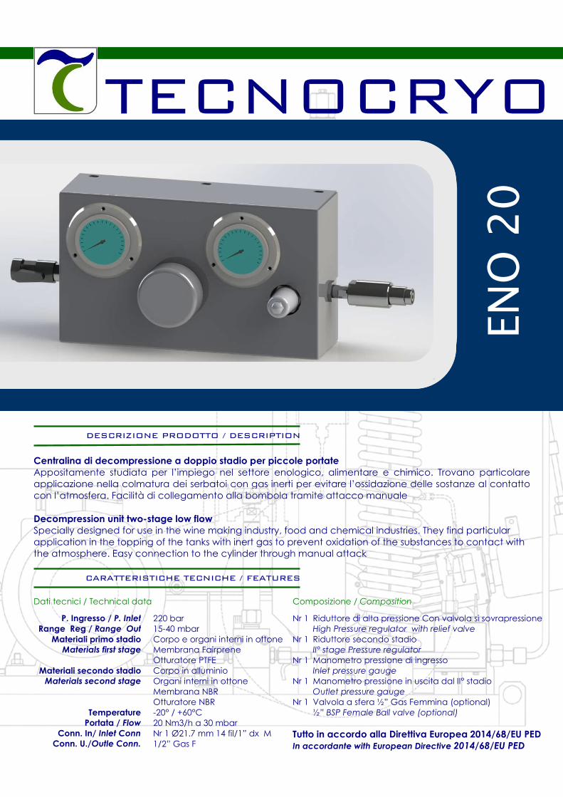
TECNOCRYO ENO 20 DESCRIZIONE PRODOTTO / DESCRIPTION Centralina di decompressione a doppio stadio per piccole portate Appositamente studiata per l’impiego nel settore enologico, alimentare e chimico. Trovano particolare applicazione nella colmatura dei serbatoi con gas inerti per evitare l’ossidazione delle sostanze al contatto con l’atmosfera. Facilità di collegamento alla bombola tramite attacco manuale Decompression unit two-stage low flow Specially designed for use in the wine making industry, food and chemical industries. They find particular application in the topping of the tanks with inert gas to prevent oxidation of the substances to contact with the atmosphere. Easy connection to the cylinder through manual attack CARATTERISTICHE TECNICHE / FEATURES P. Ingresso / P. Inlet Range Reg / Range Out Materiali primo stadio Materials first stage Materiali secondo stadio Materials second stage Temperature Portata / Flow Conn. In/ Inlet Conn Conn. U./Outle Conn. Dati tecnici / Technical data 220 bar 15-40 mbar Corpo e organi interni in ottone Membrana Fairprene Otturatore PTFE Corpo in alluminio Organi interni in ottone Membrana NBR Otturatore NBR -20° / +60°C 20 Nm3/h a 30 mbar Nr 1 Ø21.7 mm 14 fil/1” dx M 1/2” Gas F Composizione / Composition Nr 1 Riduttore di alta pressione Con valvola si sovrapressione High Pressure regulator with relief valve Nr 1 Riduttore secondo stadio II° stage Pressure regulator Nr 1 Manometro pressione di ingresso Inlet pressure gauge Nr 1 Manometro pressione in uscita dal II° stadio Outlet pressure gauge Nr 1 Valvola a sfera ½” Gas Femmina (optional) ½” BSP Female Ball valve (optional) Tutto in accordo alla Direttiva Europea 2014/68/EU PED In accordante with European Directive 2014/68/EU PED
Transcript of Flyer centralina monoutenza front Rev2 - TECNOCRYO Flyer centralina monoutenza rev2.pdf · 1/2”...
TECNOCRYO
EN
O 2
0
DESCRIZIONE PRODOTTO / DESCRIPTION
Centralina di decompressione a doppio stadio per piccole portate
Appositamente studiata per l’impiego nel settore enologico, alimentare e chimico. Trovano particolare applicazione nella colmatura dei serbatoi con gas inerti per evitare l’ossidazione delle sostanze al contatto con l’atmosfera. Facilità di collegamento alla bombola tramite attacco manuale
Decompression unit two-stage low flow Specially designed for use in the wine making industry, food and chemical industries. They find particular application in the topping of the tanks with inert gas to prevent oxidation of the substances to contact with the atmosphere. Easy connection to the cylinder through manual attack
CARATTERISTICHE TECNICHE / FEATURES
P. Ingresso / P. Inlet
Range Reg / Range Out
Materiali primo stadio
Materials first stage
Materiali secondo stadio
Materials second stage
Temperature
Portata / Flow
Conn. In/ Inlet Conn
Conn. U./Outle Conn.
Dati tecnici / Technical data
220 bar 15-40 mbar Corpo e organi interni in ottone Membrana Fairprene Otturatore PTFE Corpo in alluminio Organi interni in ottone Membrana NBR Otturatore NBR -20° / +60°C 20 Nm3/h a 30 mbar Nr 1 Ø21.7 mm 14 fil/1” dx M 1/2” Gas F
Composizione / Composition
Nr 1 Riduttore di alta pressione Con valvola si sovrapressione High Pressure regulator with relief valve
Nr 1 Riduttore secondo stadio II° stage Pressure regulator
Nr 1 Manometro pressione di ingresso Inlet pressure gauge
Nr 1 Manometro pressione in uscita dal II° stadio Outlet pressure gauge
Nr 1 Valvola a sfera ½” Gas Femmina (optional) ½” BSP Female Ball valve (optional)
Tutto in accordo alla Direttiva Europea 2014/68/EU PED In accordante with European Directive 2014/68/EU PED
Connessione alla bombola / Connection cylinder (Fig. A)
La connessione alla bombola è stata studiata per semplificare le operazioni di collegamento. Tramite questo speciale sistema è possibile sostituire la bombola senza l’uso di chiavi ma semplicemente avvitando e svitando a mano. The connection to the gas cylinder has been designed to simplify the connection operations. Through this
special system is possible to replace the cylinder without the use of keys, but simply by screwing and
unscrewing by hand Regolatore I° stadio / The regulator first stage (Fig. B)
Particolare attenzione è stata data alla realizzazione dell’otturatore del regolatori di I° stadio che realizzato in PTFE è all’interno di una capsula protetta da un filtro sinterizzato da 10 micron in bronzo
nichelato per evitare anche in presenza di impurità nel gas, il malfunzionamento della centralina mantenendo stabile la pressione di uscita impostata. La realizzazione della parte soffice in PTFE lo rende particolarmente adatto per il settore alimentare. Particular attention was given to the realization of the shutter of first stage regulators. Made of PTFE is
inside a capsule protected by a sintered filter 10 micron bronze plated to avoid even in the presence of
impurities in the gas, the malfunction of the controller maintaining a stable output pressure set. The initial
implementation of the soft PTFE makes it particularly suitable for the food industry Regolatore II° stadio / Regulator stage II (Fig. C) Il regolatore di II° è completo di una valvola di sfioro che permette, in caso di sovrapessioni accidentali, l’evacuazione controllata della pressione in eccesso
The regulator II ° is full of a relief valve which allows, in case of accidental sovrapessioni, the controlled
evacuation of the excess pressure
Tecnocryo S.p.A.Via Ugo Foscolo 8
20060 Basiano (MI)
Italy
phone: +39.02957641.20 fax: +39.02957641.02 web site: http://www.tecnocryo.com/
e-mail: [email protected]
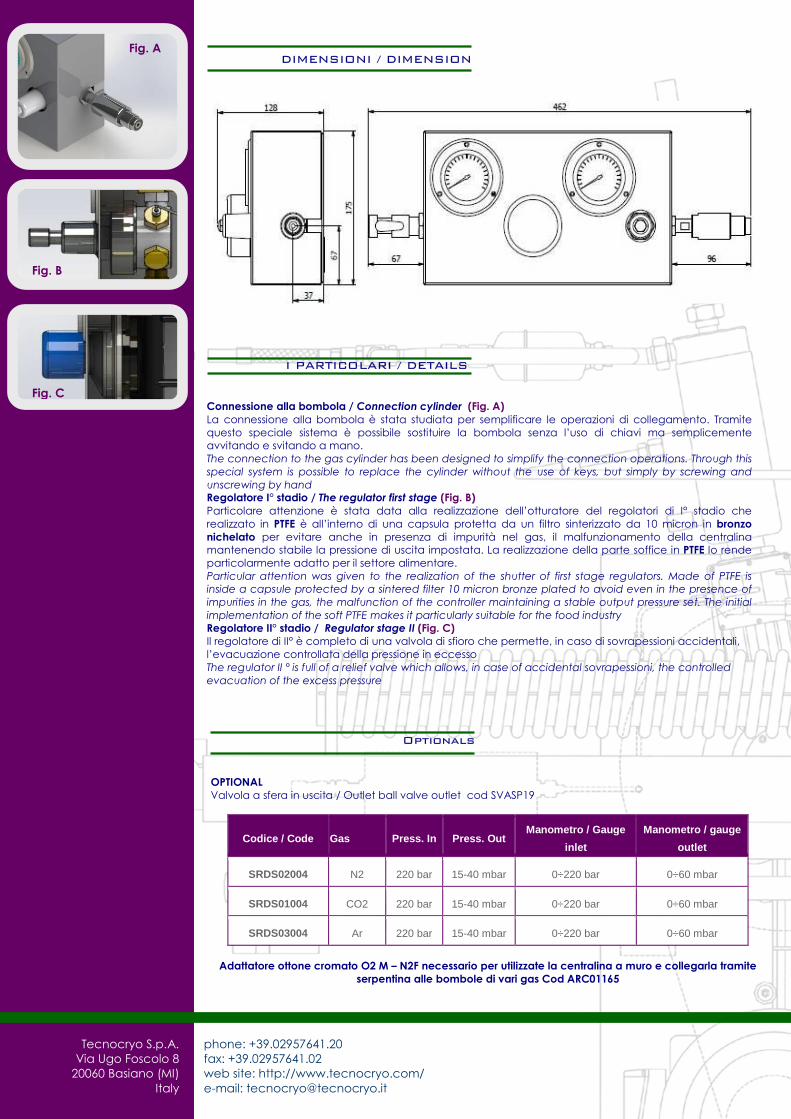
DIMENSIONI / DIMENSION
Optionals
OPTIONAL
Valvola a sfera in uscita / Outlet ball valve outlet cod SVASP19
Codice / Code Gas Press. In Press. Out Manometro / Gauge
inlet
Manometro / gauge
outlet
SRDS02004 N2 220 bar 15-40 mbar 0÷220 bar 0÷60 mbar
SRDS01004 CO2 220 bar 15-40 mbar 0÷220 bar 0÷60 mbar
SRDS03004 Ar 220 bar 15-40 mbar 0÷220 bar 0÷60 mbar
Adattatore ottone cromato O2 M – N2F necessario per utilizzate la centralina a muro e collegarla tramite
serpentina alle bombole di vari gas Cod ARC01165
I PARTICOLARI / DETAILS
Fig. B
Fig. C
Fig. C
Fig. A