FE/CE - REUS ventili s actuatorom/FIP - PVC... · FE/CE Valvola a farfalla a ... poignée et...
20
1 FE/CE Valvola a farfalla a comando elettrico Electrically actuated butterfly valve Vanne à papillon à commande électrique Absperrklappe mit mit Elektro-Antrieb • Valvola di intercettazione e rego- lazione • Gamma dimensionale da DN 40 a DN 200 mm, serie DIN 3202 K2 e ISO 5752 Medium serie 25 • Resistenza a pressioni di eserci- zio fino a 16 bar a 20° C • Materiale corpo e disco: PVC • Sistema di foratura con fori ovali che permette l’accoppiamento secondo numerosi standard internazionali • Versione manuale a leverismo con maniglia in PVC e crema- gliera in PVC • Tenuta primaria intercambiabile con manicotto in elastomero EPDM, FPM, NBR • Possibilità di installazione anche come valvola di fine linea o di scarico di fondo o rapido da ser- batoio • Attuatore elettrico realizzato su specifiche FIP • Comando manuale di serie con indicatore visivo di posizione • Due finecorsa elettrici di segna- lazione forniti di serie • Used for fast control and ON/ OFF operations • Size range: from DN 40 up to DN 200 mm, series DIN 3202 K2 and ISO 5752 Medium series 25 • Working pressure 16 bar at 20° C • One piece body, and disc mate- rial:PVC • Oval holes body to fit with flan- ges in different standards • Hand operated version with PVC hand lever and PVC ratchet • Interchangeable primary liner in elastomer EPDM, FPM, or NBR. • Possible mounting of valve as end valve, or quick discharge from tanks • Electric actuator produced on FIP specifications • Manual override and optical position indicator standard sup- plied standard • 2 Limit switches standard sup- plied. • Vanne d’arrêt et de régulation • Gamme dimensionnelle de DN 40 à DN 200 mm, série DIN 3202 K2 et ISO 5752 Médium série 25 • Pression de service jusqu’à 16 bar à 20°C • Matériau corps et papillon: PVC • Système de perçage par trous ovales permettant l’accouple- ment selon plusieurs standard s internationaux • Version manuelle à levier avec poignée et crémaillère en PVC • Manchette interchangeable en élastomère EPDM, FPM, NBR • Possibilité de montage en fin de ligne, ou sur réservoir • Actionneur électrique réalisé sur spécification technique de FIP. • Commande manuelle de série avec indicateur d’ouverture et fermeture. • 2 Micro interrupteurs fin de course standard. • Geeignet für Drossel- und Absperrfunktionen • Abmessungen von DN 40 bis DN 200 mm, entsprechend DIN 3202 K2 und ISO 5752 Baulänge mittel, Serie 25 • Höchstzulässiger Betriebsdruck 16 bar bei 20° C • Einteiliger Klappenkörper und Klappenscheibe aus PVC-U. • Vier ovale Schraubenlöcher für den Einsatz mit Flanschen nach verschiedenen Normen • Manuelle Ausführung mit ergo- nomischem Handhebel aus PVC- U mit Rastung für eine schnelle Durchflußregulierung • Der Klappenkörper ist nicht mediumberührt. Die Auskleidung ist mit der Dichtung kombiniert und auswechselbar, Ausführung in EPDM, FPM oder NBR. • Die Absperrklappe kann auch als Schnellentnahmearmatur, z.B. an Tanks eingesetzt werden. • Elektro-Antrieb nach FIP- Spezificakation. • Handbetätigung und optische Stellungsanzeige serienmassig Verfügbar. • 2 zusätzlicher Endschalter l dati del presente prospetto sono for- niti in buona fede. La FIP non si assu- me alcuna responsabilità su quei dati non direttamente derivati da norme internazionali. La FIP si riserva di apportarvi qualsiasi modifica. The data given in this leaflet are offe- red in good faith. No liability can be accepted concerning technical data that are not directly covered by reco- gnized international Standards. FIP reserves the right to carry out any modification to the products shown in this leaflet. Les données contenues dans cette bro- chure sont fournies en bonne foi. FIP n’assume aucune responsabilité pour les données qui ne dérivent pas direc- tement des normes internationales. FIP garde le droit d’apporter toute modifi- cation aux produits présentés dans cette brochure. Alle Daten dieser Druckschrift wurden nach bestem Wissen angegeben, jedoch besteht keine Verbindlichkeit, sofern sie nicht direkt internationalen Normen entnommen wurden. Die Änderung von Maßen oder Ausführungen bleibt FIP vorbehalten.
Transcript of FE/CE - REUS ventili s actuatorom/FIP - PVC... · FE/CE Valvola a farfalla a ... poignée et...
1
FE/CE
Valvola a farfalla acomando elettrico
Electrically actuatedbutterfly valve
Vanne à papillon àcommande électrique
Absperrklappe mitmit Elektro-Antrieb
• Valvola di intercettazione e rego-lazione
• Gamma dimensionale da DN 40a DN 200 mm, serie DIN 3202K2 e ISO 5752 Medium serie 25
• Resistenza a pressioni di eserci-zio fino a 16 bar a 20° C
• Materiale corpo e disco: PVC• Sistema di foratura con fori ovali
che permette l’accoppiamentosecondo numerosi standardinternazionali
• Versione manuale a leverismocon maniglia in PVC e crema-gliera in PVC
• Tenuta primaria intercambiabilecon manicotto in elastomeroEPDM, FPM, NBR
• Possibilità di installazione anchecome valvola di fine linea o discarico di fondo o rapido da ser-batoio
• Attuatore elettrico realizzato suspecifiche FIP
• Comando manuale di serie conindicatore visivo di posizione
• Due finecorsa elettrici di segna-lazione forniti di serie
• Used for fast control and ON/OFF operations
• Size range: from DN 40 up toDN 200 mm, series DIN 3202K2 and ISO 5752 Medium series25
• Working pressure 16 bar at 20°C
• One piece body, and disc mate-rial:PVC
• Oval holes body to fit with flan-ges in different standards
• Hand operated version with PVChand lever and PVC ratchet
• Interchangeable primary liner inelastomer EPDM, FPM, or NBR.
• Possible mounting of valve asend valve, or quick dischargefrom tanks
• Electric actuator produced onFIP specifications
• Manual override and opticalposition indicator standard sup-plied standard
• 2 Limit switches standard sup-plied.
• Vanne d’arrêt et de régulation• Gamme dimensionnelle de DN
40 à DN 200 mm, série DIN3202 K2 et ISO 5752 Médiumsérie 25
• Pression de service jusqu’à 16bar à 20°C
• Matériau corps et papillon: PVC• Système de perçage par trous
ovales permettant l’accouple-ment selon plusieurs standard sinternationaux
• Version manuelle à levier avecpoignée et crémaillère en PVC
• Manchette interchangeable enélastomère EPDM, FPM, NBR
• Possibilité de montage en fin deligne, ou sur réservoir
• Actionneur électrique réalisé surspécification technique de FIP.
• Commande manuelle de sérieavec indicateur d’ouverture etfermeture.
• 2 Micro interrupteurs fin decourse standard.
• Geeignet für Drossel- undAbsperrfunktionen
• Abmessungen von DN 40 bisDN 200 mm, entsprechend DIN3202 K2 und ISO 5752Baulänge mittel, Serie 25
• Höchstzulässiger Betriebsdruck16 bar bei 20° C
• Einteiliger Klappenkörper undKlappenscheibe aus PVC-U.
• Vier ovale Schraubenlöcher fürden Einsatz mit Flanschen nachverschiedenen Normen
• Manuelle Ausführung mit ergo-nomischem Handhebel aus PVC-U mit Rastung für eine schnelleDurchflußregulierung
• Der Klappenkörper ist nichtmediumberührt. Die Auskleidungist mit der Dichtung kombiniertund auswechselbar, Ausführungin EPDM, FPM oder NBR.
• Die Absperrklappe kann auch alsSchnellentnahmearmatur, z.B. anTanks eingesetzt werden.
• Elektro-Antrieb nach FIP-Spezificakation.
• Handbetätigung und optischeStellungsanzeige serienmassigVerfügbar.
• 2 zusätzlicher Endschalter
l dati del presente prospetto sono for-niti in buona fede. La FIP non si assu-me alcuna responsabilità su quei datinon direttamente derivati da normeinternazionali. La FIP si riserva diapportarvi qualsiasi modifica.
The data given in this leaflet are offe-red in good faith. No liability can beaccepted concerning technical datathat are not directly covered by reco-gnized international Standards. FIPreserves the right to carry out anymodification to the products shown inthis leaflet.
Les données contenues dans cette bro-chure sont fournies en bonne foi. FIPn’assume aucune responsabilité pourles données qui ne dérivent pas direc-tement des normes internationales. FIPgarde le droit d’apporter toute modifi-cation aux produits présentés danscette brochure.
Alle Daten dieser Druckschrift wurdennach bestem Wissen angegeben,jedoch besteht keine Verbindlichkeit,sofern sie nicht direkt internationalenNormen entnommen wurden. DieÄnderung von Maßen oderAusführungen bleibt FIP vorbehalten.
2
FE/CE
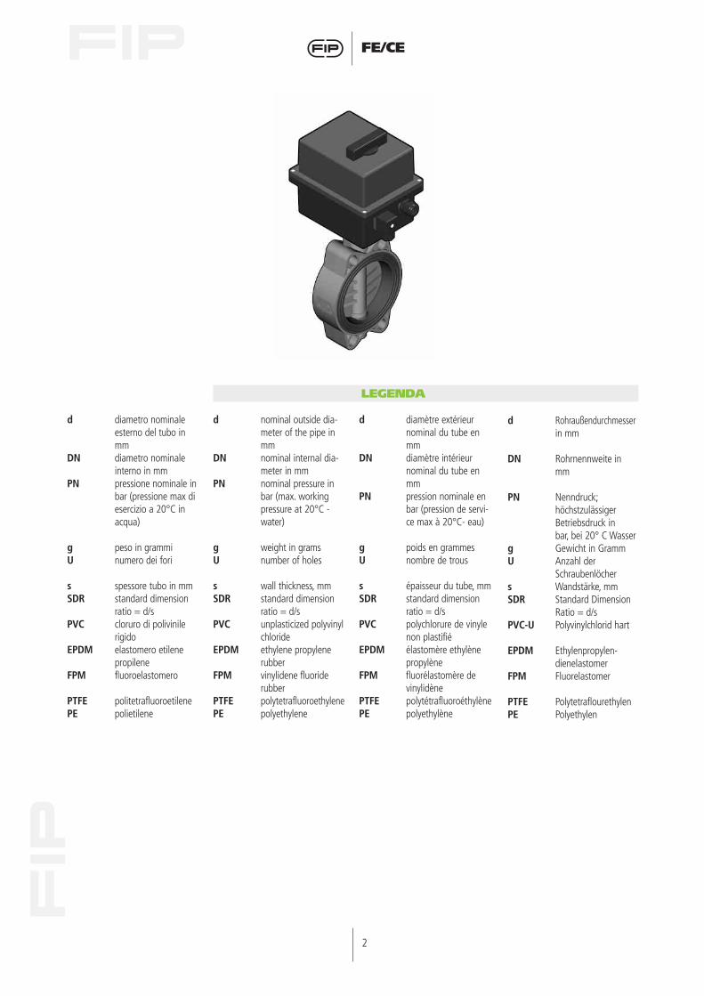
LEGENDA
d Rohraußendurchmesserin mm
DN Rohrnennweite inmm
PN Nenndruck;höchstzulässigerBetriebsdruck inbar, bei 20° C Wasser
g Gewicht in GrammU Anzahl der
Schraubenlöchers Wandstärke, mmSDR Standard Dimension
Ratio = d/sPVC-U Polyvinylchlorid hart
EPDM Ethylenpropylen-dienelastomer
FPM Fluorelastomer
PTFE PolytetraflourethylenPE Polyethylen
d nominal outside dia-meter of the pipe inmm
DN nominal internal dia-meter in mm
PN nominal pressure inbar (max. workingpressure at 20°C -water)
g weight in gramsU number of holes
s wall thickness, mmSDR standard dimension
ratio = d/sPVC unplasticized polyvinyl
chlorideEPDM ethylene propylene
rubberFPM vinylidene fluoride
rubberPTFE polytetrafluoroethylenePE polyethylene
d diametro nominaleesterno del tubo inmm
DN diametro nominaleinterno in mm
PN pressione nominale inbar (pressione max diesercizio a 20°C inacqua)
g peso in grammiU numero dei fori
s spessore tubo in mmSDR standard dimension
ratio = d/sPVC cloruro di polivinile
rigidoEPDM elastomero etilene
propileneFPM fluoroelastomero
PTFE politetrafluoroetilenePE polietilene
d diamètre extérieurnominal du tube enmm
DN diamètre intérieurnominal du tube enmm
PN pression nominale enbar (pression de servi-ce max à 20°C- eau)
g poids en grammesU nombre de trous
s épaisseur du tube, mmSDR standard dimension
ratio = d/sPVC polychlorure de vinyle
non plastifiéEPDM élastomère ethylène
propylèneFPM fluorélastomère de
vinylidènePTFE polytétrafluoroéthylènePE polyethylène
3
FE/CE
bar1614121086420
-20 0 20 40 °C60 10080
DN 40 ÷ 50
DN 65 ÷ 200
1
3
1
pres
sione
di e
serc
izio
- wor
king
pre
ssur
epr
essio
n de
ser
vice
- Bet
riebs
druc
k
temperatura di esercizio - working temperaturetempérature de service - Betriebstemperatur
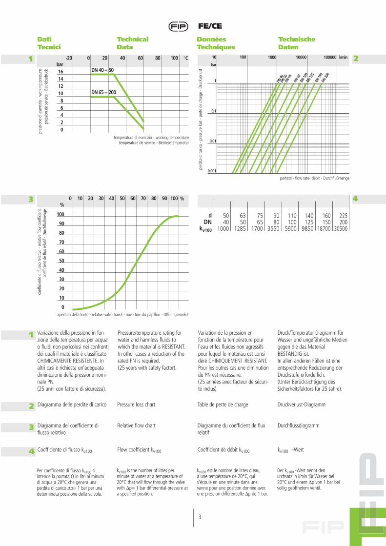
Variazione della pressione in fun-zione della temperatura per acquao fluidi non pericolosi nei confrontidei quali il materiale è classificatoCHIMICAMENTE RESISTENTE. Inaltri casi è richiesta un’adeguatadiminuzione della pressione nomi-nale PN.(25 anni con fattore di sicurezza).
Pressure/temperature rating forwater and harmless fluids towhich the material is RESISTANT.In other cases a reduction of therated PN is required.(25 years with safety factor).
Variation de la pression enfonction de la température pourl’eau et les fluides non agressifspour lequel le matériau est consi-déré CHIMIQUEMENT RESISTANT.Pour les outres cas une diminutiondu PN est nécessaire.(25 années avec facteur de sécuri-té inclus).
Druck/Temperatur-Diagramm fürWasser und ungefährliche Mediengegen die das MaterialBESTÄNDIG ist.In allen anderen Fällen ist eineentsprechende Reduzierung derDruckstufe erforderlich.(Unter Berücksichtigung desSicherheitsfaktors für 25 Jahre).
Dati Tecnici
Technical Data
Données Techniques
TechnischeDaten
DN 40
DN 50
DN 65
DN 80
DN 10
0DN
125
1000 l/min10000 10000010010
DN 15
0DN
200
bar
1
0,1
0,01
0,001
perd
ita d
i car
ico -
pres
sure
lost
- pe
rte d
e ch
arge
- Dr
uckv
erlu
st
portata - flow rate- débit - Durchflußmenge
2
%
100
90
80
70
60
50
40
30
20
10
0
0 10 20 30 %40 10050 60 70 80 90
apertura della lente - relative valve travel - ouverture du papillon - Offnungswinkel
coef
ficie
nte
di fl
usso
rela
tivo
- rel
ative
flow
coe
fficie
ntco
effic
ient
de
flux
rela
tif -
Durc
hflu
ßmen
ge
4
7565
1700
5040
1000
6350
1285
dDN
kv100
9080
3550
110100
5900
140125
9850
225200
30500
160150
18700
Per coefficiente di flusso kv100 siintende la portata Q in litri al minutodi acqua a 20°C che genera unaperdita di carico ∆p= 1 bar per unadeterminata posizione della valvola.
kv100 is the number of litres perminute of water at a temperature of20°C that will flow through the valvewith ∆p= 1 bar differential-pressure ata specified position.
kv100 est le nombre de litres d’eau,à une température de 20°C, quis’écoule en une minute dans unevanne pour une position donnée avecune pression différentielle ∆p de 1 bar.
Der kv100 -Wert nennt denurchsatz in l/min für Wasser bei20°C und einem ∆p von 1 bar beivöllig geöffnetem Ventil.
2 Diagramma delle perdite di carico Pressure loss chart Table de perte de charge Druckverlust-Diagramm
3 Diagramma del coefficiente di flusso relativo
Relative flow chart Diagramme du coefficient de fluxrelatif
Durchflussdiagramm
4 Coefficiente di flusso kv100 Flow coefficient kv100 Coefficient de débit kv100 kv100 –Wert

4
FE/CE
Dimensioni Dimensions Dimensions Dimensionen
Le dimensioni di ingombro dellavalvola a farfalla FE sono in accor-do con la norma ISO 5752Medium Serie 25 e DIN 3202 K2.La foratura del corpo permettel’accoppiamento con dimensioni diforatura secondo le seguentinorme internazionali:- DIN 2501, ISO DIS 9624,UNI 2223- BS 10 table D/E (DN 250 E)- ASA ANSI B16,5 class 150- JIS 2212 (K10 ad esclusioneDN 200), JIS 2212(K5 ad esclusione DN 50)
The overall dimensions of the FEbutterfly valve comply with thefollowing standards: ISO 5752Medium Serie 25 and DIN 3202K2.Oval holes in the valve body allowconnections to flanges with diffe-rent drillings:- DIN 2501, ISO DIS 9624,UNI 2223- BS 10 table D/E- ASA B16,5 class 150- JIS 2212 (K10 except for DN 200), JIS 2212(K5 except for DN 50)
Les dimensions d’encombrementde la vanne à papillon FE sontconformes aux normes ISO 5752Medium Serie 25 et DIN 3202 K2.Le perçage du corps permet l’ac-couplement suivant les nor mesinternationales:- DIN 2501, ISO DIS 9624,UNI 2223- BS 10 table D/E- ASA B16,5 class 150- JIS 2212 (K10 sauf DN 200),JIS 2212 (K5 sauf DN 50)
Die Baulängen der FEAbsperrklappen entsprechen denfolgenden Normen: ISO 5752Medium Serie 25 und DIN 3202K2.Ovale Schraubenlöcher imKlappengehäuse ermöglichen denEinbau zwischen Flansche mitAnschlußmaßen nach folgendenNormen:- DIN 2501, ISO DIS 9624,UNI 2223- BS 10 table D/E- ASA B 16,5 Class 150- JIS 2212 (K 10 mit AusnahmeDN 200), JIS 2212(K5 mit Ausnahme DN 50)
FEOV/CE
VALVOLA A FARFALLA in PVC acomando elettrico
PVC BUTTERFLY VALVE electricallyactuated
VANNE PAPILLON en PVC à commande electrique
PVC-U ABSPERRKLAPPE mitElektro- Antrieb
* FEOV d 140 con collari adattatorispeciali d 125** FEOV d 225 con collari adattatorispeciali d 200
* FEOV d 140 with special adaptorstubs d 125** FEOV d 225 with special adaptorstubs d 200
* FEOV d 140 avec spéciales colletsd’adaptation d 125** FEOV d 225 avec spéciales colletsd’adaptation d 200
* FEOV d 140 mit besonderenBundbuchsen d 125** FEOV d 225 mit besonderenBundbuchsen d 200
d
50637590
110125*-140
160200**-225
DN
40506580
100125150200
PN
1616101010101010
B2
60708093
105121132161
B7
253259266309323379392493
T1
189189189188188188188200
T2
929292
128128128128185
T3
919191
95,595,5
4747
58,5
H
132147165130150185210325
Z
3343464956647071
Amin
93108128145165204230280
Amax
109124144159190215242298
f
1919191919232323
g
2074225424803700405065007200
14460
U
44444448
5
FE/CE
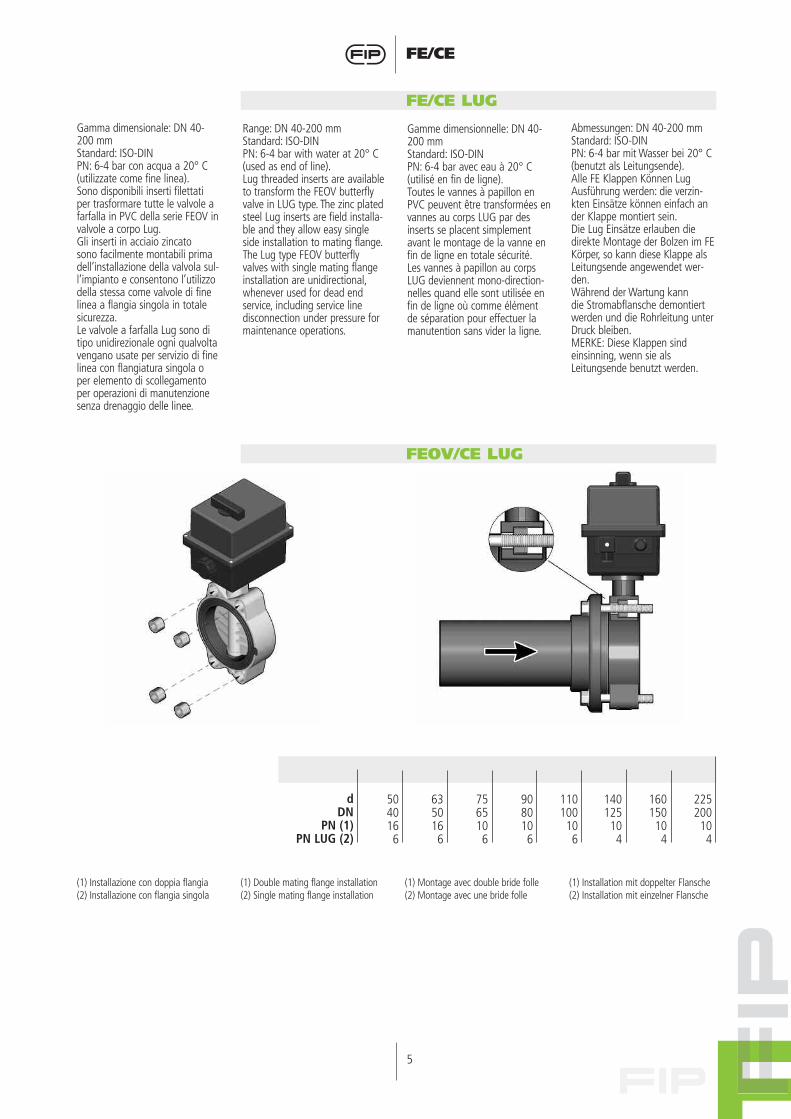
(1) Installazione con doppia flangia(2) Installazione con flangia singola
(1) Double mating flange installation(2) Single mating flange installation
(1) Montage avec double bride folle(2) Montage avec une bride folle
(1) Installation mit doppelter Flansche(2) Installation mit einzelner Flansche
FE/CE LUG
FEOV/CE LUG
Gamma dimensionale: DN 40-200 mmStandard: ISO-DINPN: 6-4 bar con acqua a 20° C(utilizzate come fine linea).Sono disponibili inserti filettatiper trasformare tutte le valvole afarfalla in PVC della serie FEOV invalvole a corpo Lug.Gli inserti in acciaio zincatosono facilmente montabili primadell’installazione della valvola sul-l’impianto e consentono l’utilizzodella stessa come valvole di finelinea a flangia singola in totalesicurezza.Le valvole a farfalla Lug sono ditipo unidirezionale ogni qualvoltavengano usate per servizio di finelinea con flangiatura singola oper elemento di scollegamentoper operazioni di manutenzionesenza drenaggio delle linee.
Range: DN 40-200 mmStandard: ISO-DINPN: 6-4 bar with water at 20° C(used as end of line).Lug threaded inserts are availableto transform the FEOV butterflyvalve in LUG type. The zinc platedsteel Lug inserts are field installa-ble and they allow easy singleside installation to mating flange.The Lug type FEOV butterflyvalves with single mating flangeinstallation are unidirectional,whenever used for dead endservice, including service linedisconnection under pressure formaintenance operations.
Gamme dimensionnelle: DN 40-200 mmStandard: ISO-DINPN: 6-4 bar avec eau à 20° C(utilisé en fin de ligne).Toutes le vannes à papillon enPVC peuvent être transformées envannes au corps LUG par desinserts se placent simplementavant le montage de la vanne enfin de ligne en totale sécurité.Les vannes à papillon au corpsLUG deviennent mono-direction-nelles quand elle sont utilisée enfin de ligne où comme élémentde séparation pour effectuer lamanutention sans vider la ligne.
Abmessungen: DN 40-200 mmStandard: ISO-DINPN: 6-4 bar mit Wasser bei 20° C(benutzt als Leitungsende).Alle FE Klappen Können LugAusführung werden: die verzin-kten Einsätze können einfach ander Klappe montiert sein.Die Lug Einsätze erlauben diedirekte Montage der Bolzen im FEKörper, so kann diese Klappe alsLeitungsende angewendet wer-den.Während der Wartung kanndie Stromabflansche demontiertwerden und die Rohrleitung unterDruck bleiben.MERKE: Diese Klappen sindeinsinning, wenn sie alsLeitungsende benutzt werden.
7565106
5040166
6350166
dDN
PN (1)PN LUG (2)
9080106
110100106
140125104
225200104
160150104
6
FE/CE
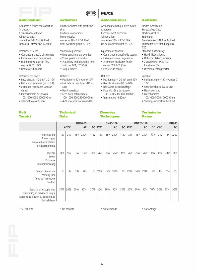
Automatismi Actuators Automatismes Antriebe
Attuatore elettrico con coperturain plastica.Connessioni elettricheAlimentazione:connettore DIN 43650 3P+TFinecorsa: pressacavo ISO 020
Dotazioni di serie:• Comando manuale di sicurezza• Indicatore visivo di posizione• Due finecorsa ausiliari (5A)
regolabili FC1, FC2.• Limitatore di coppia
Dotazioni opzionali:• Posizionatore 4-20 mA o 0-10V• Batteria di sicurezza (NC o NA)• elemento riscaldante (anticon-
densa)• Potenziometro di risposta
100,1000,5000,10000 Ohm • Trasmettitore 4-20 mA
Electric actuator with plastic hou-sing.Electrical connectionsPower supply:connector DIN 43650 3P+TLimit switches: gland ISO 020
Standard equipment:• Emergency manual override• Visual position indicator• 2 auxiliary and adjustable limit
switches FC1, FC2 (5A)• Torque limiter
Options:• Positioner 4-20 mA or 0-10V• Fail safe security block (NC o
NO)• Heating resistor• Feed back potentiometer
100,1000,5000,10000 Ohms• 4-20 mA position transmitter.
Actionneur électrique avec plastic capotage.Raccordement éléctriqueAlimentation:connecteur DIN 43650 3P+TFin de course: raccord ISO 020
Equipement standard:• Commande manuelle de secours• Indicateur visual de position• 2 contacts auxiliaires fin de
course FC1, FC2 (5A)• Limiteur de couple
Options:• Positionneur 4-20 mA ou 0-10V• Bloc de sécurité (NF ou NO)• Résistance de réchauffage• Potentiomètre de recopie
100,1000,5000,10000 Ohms• Transmetteur 4-20mA
Elektro-Antrieb mitKunststoffgehäuseElektroanschlussSpannung:Geratestecker DIN 43650 3P+TEndshalter: Verschraubung ISO020Standard Ausführung:• Handhilfsbetätigung• Optische Stellungsanzeige• 2 zusätzlicher FC1, FC2
Endshalter (5A)• Drehmomentbegrenzter
Zubehör:• Stellungsregler 4-20 mA oder 0-
10V• Sicherheitsblock (NC o NO)• Heizwiderstand• Potentiometer
100,1000,5000,10000 Ohms• Stellungsruckmelder 4-20 mA
AC/DC
24V
45w
33s
50%
AlimentazionePower supply
Tension d’alimentationBetriebsspannung
PotenzaPower
Puissance Aufnahmeleistung
Tempo di manovraWorking time
Temp de manoeuvre Stellzeit
Esercizio alla coppia maxDuty rating at maximum torque
Durée sous tension au couple maxiEinshaltdauer
DN200AC
220V
38w
65s
50%
115V
38w
65s
50%
DC
12V
45w
33s
50%
AC/DC
24V
26w
25/40s
30%
DN125-150AC
220V
26w
25/40s
30%
115V
26w
25/40s
30%
DC
*12V
45w
20s
30%
AC/DC
24V
26w
12/20s
30%
DN80-100AC
220V
26w
12/20s
30%
115V
26w
12/20s
30%
DC
*12V
26w
8s
30%
AC/DC
24V
26w
4s
30%
DN40-65AC
220V
15w
20s
50%
115V
15w
20s
50%
12V
26w
8s
30%
* Su richiesta * On request * Sur demande * Auf Anfrage
Dati Tecnici
Technical Data
Données Techniques
TechnischeDaten

7
FE/CE
FEOV/CE DN 40-65
Schema elettrico115V - 230 V AC (50Hz)
Electric wiring115V - 230 V AC (50Hz)
Schema electrique115V - 230 V AC (50Hz)
Shaltbild115V - 230 V AC (50Hz)
Schema elettrico12V - 24V AC (50Hz) / DC
Electric wiring12V - 24V AC (50Hz) / DC
Schema electrique12V - 24V AC (50Hz) / DC
Shaltbild12V - 24V AC (50Hz) / DC
8
FE/CE
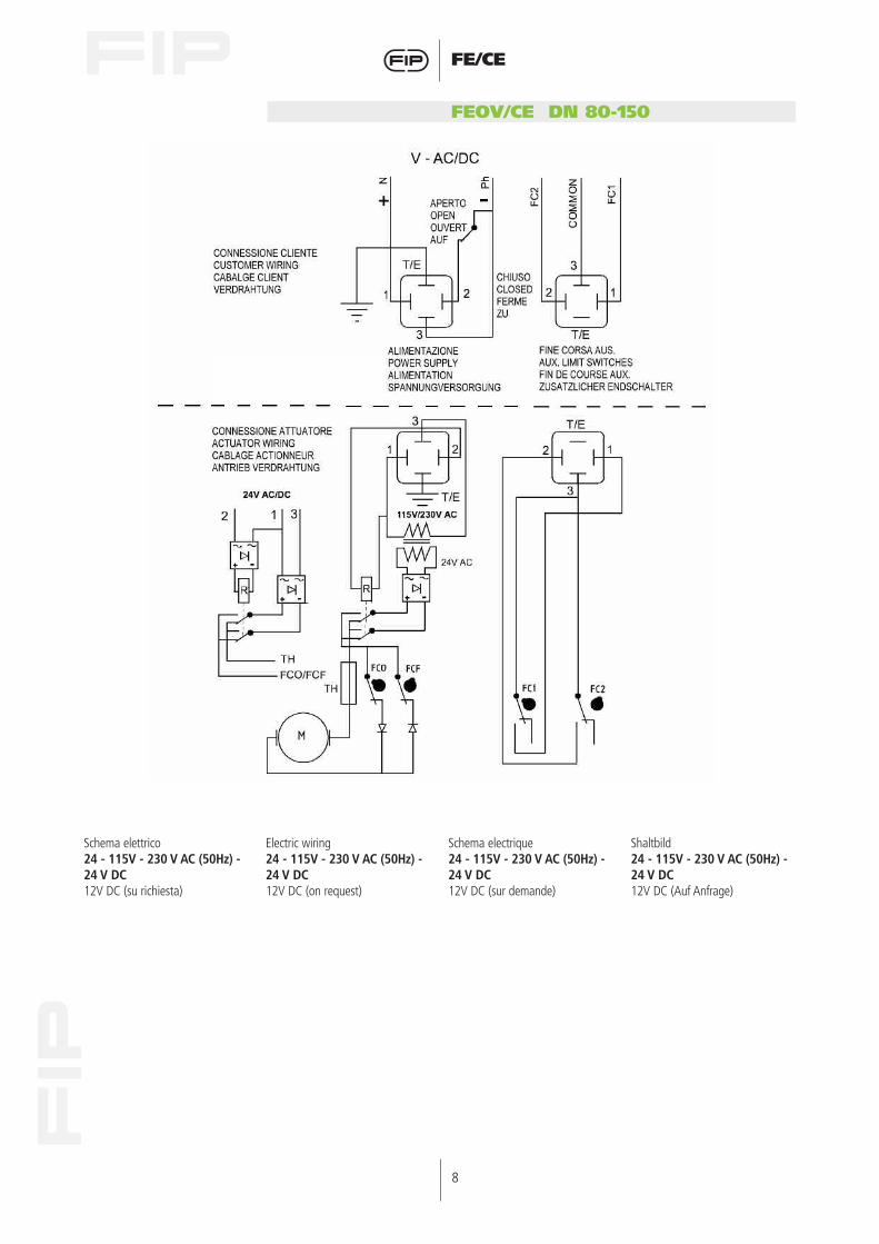
FEOV/CE DN 80-150
Schema elettrico24 - 115V - 230 V AC (50Hz) -24 V DC12V DC (su richiesta)
Electric wiring24 - 115V - 230 V AC (50Hz) -24 V DC12V DC (on request)
Schema electrique24 - 115V - 230 V AC (50Hz) -24 V DC12V DC (sur demande)
Shaltbild24 - 115V - 230 V AC (50Hz) -24 V DC12V DC (Auf Anfrage)
9
FE/CE
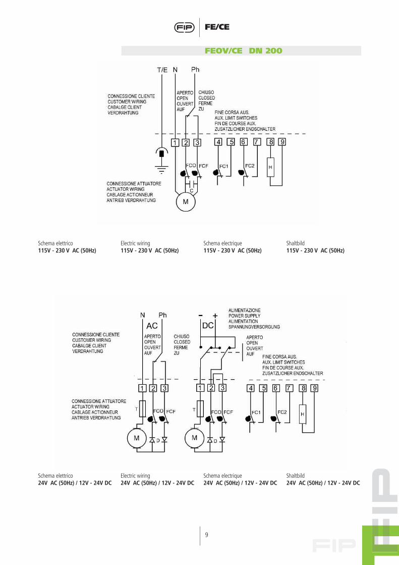
FEOV/CE DN 200
Schema elettrico115V - 230 V AC (50Hz)
Electric wiring115V - 230 V AC (50Hz)
Schema electrique115V - 230 V AC (50Hz)
Shaltbild115V - 230 V AC (50Hz)
Schema elettrico24V AC (50Hz) / 12V - 24V DC
Electric wiring24V AC (50Hz) / 12V - 24V DC
Schema electrique24V AC (50Hz) / 12V - 24V DC
Shaltbild24V AC (50Hz) / 12V - 24V DC
10
FE/CE
Accessori attuatore
Actuator accessories
Accessoires pour l’actionneur
Antriebe Zubehör
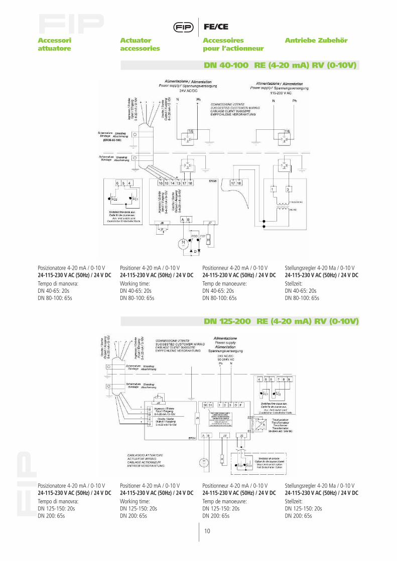
DN 40-100 RE (4-20 mA) RV (0-10V)
Posizionatore 4-20 mA / 0-10 V24-115-230 V AC (50Hz) / 24 V DCTempo di manovra:DN 40-65: 20sDN 80-100: 65s
Positioner 4-20 mA / 0-10 V24-115-230 V AC (50Hz) / 24 V DCWorking time:DN 40-65: 20sDN 80-100: 65s
Positionneur 4-20 mA / 0-10 V24-115-230 V AC (50Hz) / 24 V DCTemp de manoeuvre:DN 40-65: 20sDN 80-100: 65s
Stellungsregler 4-20 Ma / 0-10 V24-115-230 V AC (50Hz) / 24 V DCStellzeit:DN 40-65: 20sDN 80-100: 65s
DN 125-200 RE (4-20 mA) RV (0-10V)
Posizionatore 4-20 mA / 0-10 V24-115-230 V AC (50Hz) / 24 V DCTempo di manovra:DN 125-150: 20sDN 200: 65s
Positioner 4-20 mA / 0-10 V24-115-230 V AC (50Hz) / 24 V DCWorking time:DN 125-150: 20sDN 200: 65s
Positionneur 4-20 mA / 0-10 V24-115-230 V AC (50Hz) / 24 V DCTemp de manoeuvre:DN 125-150: 20sDN 200: 65s
Stellungsregler 4-20 Ma / 0-10 V24-115-230 V AC (50Hz) / 24 V DCStellzeit:DN 125-150: 20sDN 200: 65s

11
FE/CE
FS BLOCK (NC-NO) 230VAC INPUT/OUTPUT
Batteria di sicurezza (NC o NA)per attuatori 230V AC
Fail safe security block (NC o NO)for 230 VAC actuators
Bloc de sécurité (NF ou NO) pouractionneur 230 VAC
Sicherheitsblock (NC o NO) fürAntrieb 230VAC
Accessori attuatore
Actuator accessories
Accessoires pour l’actionneur
Antriebe Zubehör
12
FE/CE
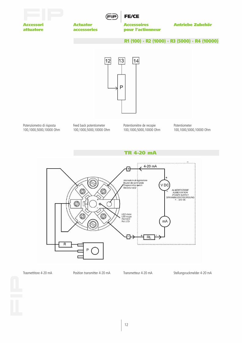
R1 (100) - R2 (1000) - R3 (5000) - R4 (10000)
Potenziometro di risposta100,1000,5000,10000 Ohm
Feed back potentiometer100,1000,5000,10000 Ohm
Potentiomètre de recopie100,1000,5000,10000 Ohm
Potentiometer100,1000,5000,10000 Ohm
Trasmettitore 4-20 mA Position transmitter 4-20 mA Transmetteur 4-20 mA Stellungsruckmelder 4-20 mA
TR 4-20 mA
Accessori attuatore
Actuator accessories
Accessoires pour l’actionneur
Antriebe Zubehör
13
FE/CE
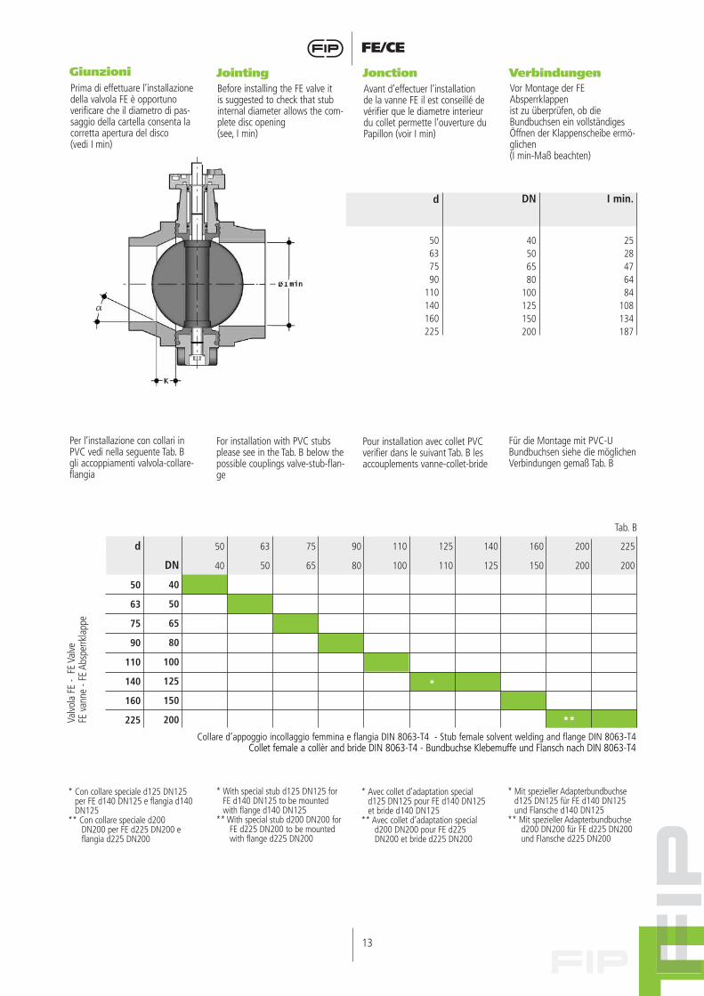
Giunzioni Jointing Jonction VerbindungenPrima di effettuare l’installazionedella valvola FE è opportunoverificare che il diametro di pas-saggio della cartella consenta lacorretta apertura del disco(vedi I min)
Before installing the FE valve itis suggested to check that stubinternal diameter allows the com-plete disc opening(see, I min)
Avant d’effectuer l’installationde la vanne FE il est conseillé devérifier que le diametre interieurdu collet permette l’ouverture duPapillon (voir I min)
Vor Montage der FEAbsperrklappenist zu überprüfen, ob dieBundbuchsen ein vollständigesÖffnen der Klappenscheibe ermö-glichen(I min-Maß beachten)
Per l’installazione con collari inPVC vedi nella seguente Tab. Bgli accoppiamenti valvola-collare-flangia
For installation with PVC stubsplease see in the Tab. B below thepossible couplings valve-stub-flan-ge
Pour installation avec collet PVCverifier dans le suivant Tab. B lesaccouplements vanne-collet-bride
Für die Montage mit PVC-UBundbuchsen siehe die möglichenVerbindungen gemaß Tab. B
d
50637590
110140160225
DN
40506580
100125150200
I min.
2528476484
108134187
Collare d’appoggio incollaggio femmina e flangia DIN 8063-T4 - Stub female solvent welding and flange DIN 8063-T4Collet female a collèr and bride DIN 8063-T4 - Bundbuchse Klebemuffe und Flansch nach DIN 8063-T4
d
50
63
75
90
110
140
160
225
50
40
63
50
75
65
90
80
110
100
125
110
*
140
125
160
150
200
200
**
225
200DN
40
50
65
80
100
125
150
200Valvo
la F
E -
FE V
alve
FE v
anne
- FE
Abs
perrk
lapp
e
Tab. B
* Con collare speciale d125 DN125per FE d140 DN125 e flangia d140DN125
** Con collare speciale d200DN200 per FE d225 DN200 eflangia d225 DN200
* With special stub d125 DN125 forFE d140 DN125 to be mountedwith flange d140 DN125
** With special stub d200 DN200 forFE d225 DN200 to be mountedwith flange d225 DN200
* Avec collet d’adaptation speciald125 DN125 pour FE d140 DN125et bride d140 DN125
** Avec collet d’adaptation speciald200 DN200 pour FE d225DN200 et bride d225 DN200
* Mit spezieller Adapterbundbuchsed125 DN125 für FE d140 DN125und Flansche d140 DN125
** Mit spezieller Adapterbundbuchsed200 DN200 für FE d225 DN200und Flansche d225 DN200
14
FE/CE
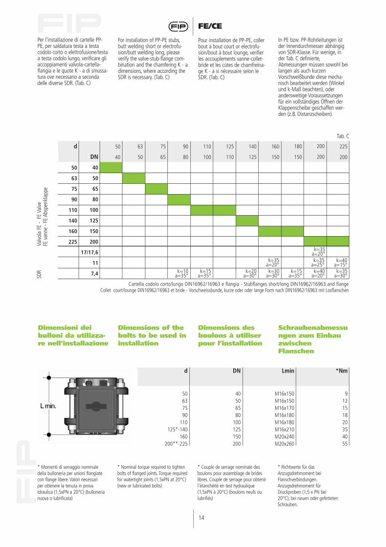
Per l’installazione di cartelle PP-PE, per saldatura testa a testacodolo corto o elettrofusione/testaa testa codolo lungo, verificare gliaccoppiamenti valvola-cartella-flangia e le quote K - a di smussa-tura ove necessario a secondadelle diverse SDR. (Tab. C)
For installation of PP-PE stubs,butt welding short or electrofu-sion/butt welding long, pleaseverify the valve-stub-flange com-bination and the chamfering K - adimensions, where according theSDR is necessary. (Tab. C)
Pour installation de PP-PE, collerbout a bout court or electrofu-sion/bout à bout lounge, verifierles accouplements vanne-collet-bride et les cùtes de chamfreina-ge K - a si nécessaire selon leSDR. (Tab. C)
In PE bzw. PP-Rohrleitungen istder Innendurchmesser abhängigvon SDR-Klasse. Für wenige, inder Tab. C definierte,Abmessungen müssen sowohl beilangen als auch kurzenVorschweißbunde diese mecha-nisch bearbeitet werden (Winkelund k-Maß beachten), oderandersweitige Voraussetzungenfür ein vollständiges Öffnen derKlappenscheibe geschaffen wer-den (z.B. Distanzscheiben).
Dimensioni deibulloni da utilizza-re nell’installazione
Dimensions of thebolts to be used ininstallation
Dimensions desboulons à utiliserpour l’installation
Schraubenabmessungen zum EinbauzwischenFlanschen
d
50637590
110125*-140
160200**-225
DN
40506580
100125150200
Lmin
M16x150M16x150M16x170M16x180M16x180M16x210M20x240M20x260
*Nm
912151820354055
* Momenti di serraggio nominaledella bulloneria per unioni flangiatecon flange libere. Valori necessariper ottenere la tenuta in provaidraulica (1,5xPN a 20°C) (bullonerianuova o lubrificata)
* Nominal torque required to tightenbolts of flanged joints. Torque requiredfor watertight joints (1,5xPN at 20°C)(new or lubricated bolts)
* Couple de serrage nominale desboulons pour assemblage de brideslibres. Couple de serrage pour obtenirl’étanchéité en test hydraulique(1,5xPN à 20°C) (boulons neufs oulubrifiés)
* Richtwerte für dasAnzugsdrehmoment beiFlanschverbindungen.Anzugsdrehmoment fürDruckproben (1,5 x PN bei20°C), bei neuen oder gefettetenSchrauben.
k=35a=20°
k=10a=35°
k=15a=35°
k=20a=30°
k=30a=30°
k=40a=15°k=35
a=30°
k=35a=25°
k=35a=20°
k=40a=20°
k=15a=35°
Cartella codolo corto/lungo DIN16962/16963 e flangia - Stubflanges short/long DIN16962/16963 and flangeCollet court/lounge DIN16962/16963 et bride - Vorschweissbunde, kurze oder oder lange Form nach DIN16962/16963 mit Losflanschen
d
50
63
75
90
110
140
160
225
50
40
63
50
75
65
90
80
110
100
125
110
140
125
160
150
180
150
200
200
225
200DN
40
50
65
80
100
125
150
200
17/17,6
11
7,4
Valvo
la F
E -
FE V
alve
FE v
anne
- FE
Abs
perrk
lapp
eSD
R
Tab. C
15
FE/CE
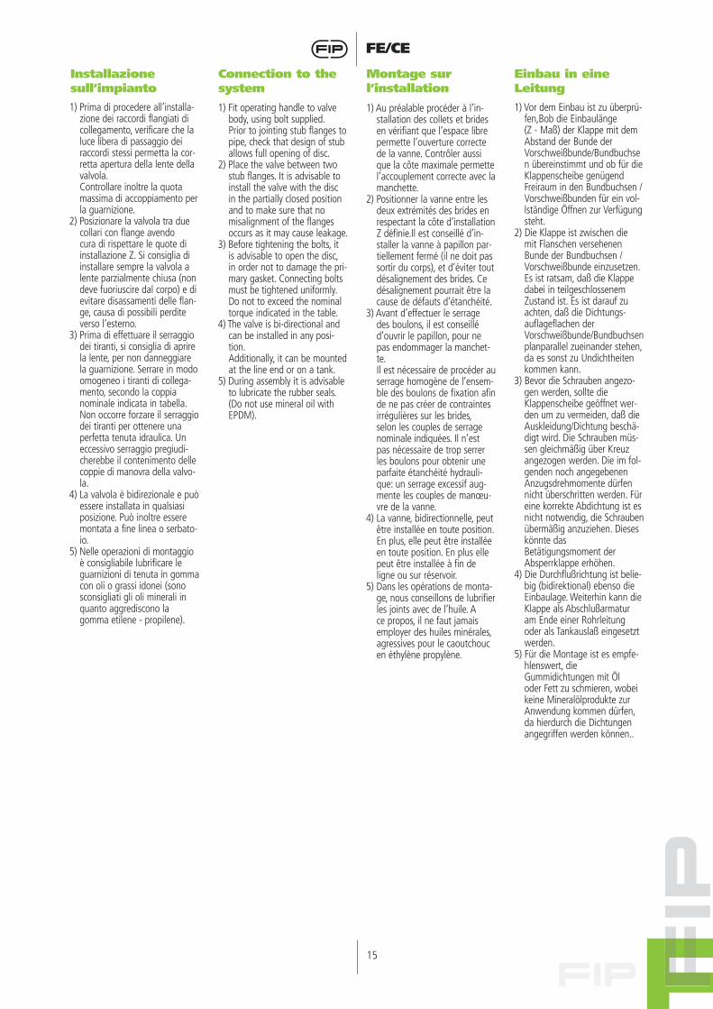
Installazione sull’impianto
Connection to thesystem
Montage sur l’installation
Einbau in eine Leitung
1) Prima di procedere all’installa-zione dei raccordi flangiati dicollegamento, verificare che laluce libera di passaggio deiraccordi stessi permetta la cor-retta apertura della lente dellavalvola.Controllare inoltre la quotamassima di accoppiamento perla guarnizione.
2) Posizionare la valvola tra duecollari con flange avendocura di rispettare le quote diinstallazione Z. Si consiglia diinstallare sempre la valvola alente parzialmente chiusa (nondeve fuoriuscire dal corpo) e dievitare disassamenti delle flan-ge, causa di possibili perditeverso l’esterno.
3) Prima di effettuare il serraggiodei tiranti, si consiglia di aprirela lente, per non danneggiarela guarnizione. Serrare in modoomogeneo i tiranti di collega-mento, secondo la coppianominale indicata in tabella.Non occorre forzare il serraggiodei tiranti per ottenere unaperfetta tenuta idraulica. Uneccessivo serraggio pregiudi-cherebbe il contenimento dellecoppie di manovra della valvo-la.
4) La valvola è bidirezionale e puòessere installata in qualsiasiposizione. Può inoltre esseremontata a fine linea o serbato-io.
5) Nelle operazioni di montaggioè consigliabile lubrificare leguarnizioni di tenuta in gommacon oli o grassi idonei (sonosconsigliati gli oli minerali inquanto aggrediscono lagomma etilene - propilene).
1) Fit operating handle to valvebody, using bolt supplied.Prior to jointing stub flanges topipe, check that design of stuballows full opening of disc.
2) Place the valve between twostub flanges. It is advisable toinstall the valve with the discin the partially closed positionand to make sure that nomisalignment of the flangesoccurs as it may cause leakage.
3) Before tightening the bolts, itis advisable to open the disc,in order not to damage the pri-mary gasket. Connecting boltsmust be tightened uniformly.Do not to exceed the nominaltorque indicated in the table.
4) The valve is bi-directional andcan be installed in any posi-tion.Additionally, it can be mountedat the line end or on a tank.
5) During assembly it is advisableto lubricate the rubber seals.(Do not use mineral oil withEPDM).
1) Au préalable procéder à l’in-stallation des collets et bridesen vérifiant que l’espace librepermette l’ouverture correctede la vanne. Contrôler aussique la côte maximale permettel’accouplement correcte avec lamanchette.
2) Positionner la vanne entre lesdeux extrémités des brides enrespectant la côte d’installationZ définie.Il est conseillé d’in-staller la vanne à papillon par-tiellement fermé (il ne doit passortir du corps), et d’éviter toutdésalignement des brides. Cedésalignement pourrait être lacause de défauts d’étanchéité.
3) Avant d’effectuer le serragedes boulons, il est conseilléd’ouvrir le papillon, pour nepas endommager la manchet-te.Il est nécessaire de procéder auserrage homogène de l’ensem-ble des boulons de fixation afinde ne pas créer de contraintesirrégulières sur les brides,selon les couples de serragenominale indiquées. Il n’estpas nécessaire de trop serrerles boulons pour obtenir uneparfaite étanchéité hydrauli-que: un serrage excessif aug-mente les couples de manœu-vre de la vanne.
4) La vanne, bidirectionnelle, peutêtre installée en toute position.En plus, elle peut être installéeen toute position. En plus ellepeut être installée à fin deligne ou sur réservoir.
5) Dans les opérations de monta-ge, nous conseillons de lubrifierles joints avec de l’huile. Ace propos, il ne faut jamaisemployer des huiles minérales,agressives pour le caoutchoucen éthylène propylène.
1) Vor dem Einbau ist zu überprü-fen,Bob die Einbaulänge(Z - Maß) der Klappe mit demAbstand der Bunde derVorschweißbunde/Bundbuchsen übereinstimmt und ob für dieKlappenscheibe genügendFreiraum in den Bundbuchsen /Vorschweißbunden für ein vol-lständige Öffnen zur Verfügungsteht.
2) Die Klappe ist zwischen diemit Flanschen versehenenBunde der Bundbuchsen /Vorschweißbunde einzusetzen.Es ist ratsam, daß die Klappedabei in teilgeschlossenemZustand ist. Es ist darauf zuachten, daß die Dichtungs-auflageflachen derVorschweißbunde/Bundbuchsenplanparallel zueinander stehen,da es sonst zu Undichtheitenkommen kann.
3) Bevor die Schrauben angezo-gen werden, sollte dieKlappenscheibe geöffnet wer-den um zu vermeiden, daß dieAuskleidung/Dichtung beschä-digt wird. Die Schrauben müs-sen gleichmäßig über Kreuzangezogen werden. Die im fol-genden noch angegebenenAnzugsdrehmomente dürfennicht überschritten werden. Füreine korrekte Abdichtung ist esnicht notwendig, die Schraubenübermäßig anzuziehen. Dieseskönnte dasBetätigungsmoment derAbsperrklappe erhöhen.
4) Die Durchflußrichtung ist belie-big (bidirektional) ebenso dieEinbaulage. Weiterhin kann dieKlappe als Abschlußarmaturam Ende einer Rohrleitungoder als Tankauslaß eingesetztwerden.
5) Für die Montage ist es empfe-hlenswert, dieGummidichtungen mit Öloder Fett zu schmieren, wobeikeine Mineralölprodukte zurAnwendung kommen dürfen,da hierdurch die Dichtungenangegriffen werden können..
16
FE/CE
7) Einbaulage (Winkel derKlappenwelle zurWaagerechten) inAbhängigkeit des Zustandesdes zu fördernden Mediums:
- Medium stark verschmutztmin. 45°
- Medium mit Schwebepartikelnwaagerecht
- Medium nicht verunreinigtsenkrecht
- Angetriebene Klappen sollten,richtig eingebaut werden (fig.1).
- Ein schnelles Schließen vonArmaturen ist zu vermeiden,um Druckstöße die durchWasserschläge entstehen, zuverhindern. Rohrsysteme kön-nen hierdurch zerstört werden.Aus diesem Grunde solltenSchneckenradgetriebe instal-liert werden, die auf Anfragelieferbar sind.
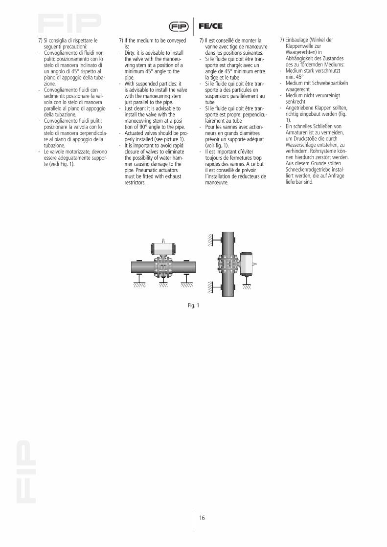
7) Si consiglia di rispettare leseguenti precauzioni:
- Convogliamento di fluidi nonpuliti: posizionamento con lostelo di manovra inclinato diun angolo di 45° rispetto alpiano di appoggio della tuba-zione.
- Convogliamento fluidi consedimenti: posizionare la val-vola con lo stelo di manovraparallelo al piano di appoggiodella tubazione.
- Convogliamento fluidi puliti:posizionare la valvola con lostelo di manovra perpendicola-re al piano di appoggio dellatubazione.
- Le valvole motorizzate, devonoessere adeguatamente suppor-te (vedi Fig. 1).
Fig. 1
7) If the medium to be conveyedis:
- Dirty: it is advisable to installthe valve with the manoeu-vring stem at a position of aminimum 45° angle to thepipe.
- With suspended particles: itis advisable to install the valvewith the manoeuvring stemjust parallel to the pipe.
- Just clean: it is advisable toinstall the valve with themanoeuvring stem at a posi-tion of 90° angle to the pipe.
- Actuated valves should be pro-perly installed (see picture 1).
- It is important to avoid rapidclosure of valves to eliminatethe possibility of water ham-mer causing damage to thepipe. Pneumatic actuatorsmust be fitted with exhaustrestrictors.
7) Il est conseillé de monter lavanne avec tige de manœuvredans les positions suivantes:
- Si le fluide qui doit être tran-sporté est chargé: avec unangle de 45° minimum entrela tige et le tube
- Si le fluide qui doit être tran-sporté a des particules ensuspension: parallèlement autube
- Si le fluide qui doit être tran-sporté est propre: perpendicu-lairement au tube
- Pour les vannes avec action-neurs en grands diamètresprévoir un supporte adéquat(voir fig. 1).
- Il est important d’évitertoujours de fermetures troprapides des vannes. A ce butil est conseillé de prévoirl’installation de réducteurs demanœuvre.
17
FE/CE
Smontaggio(DN 40-200)
Disassembly(DN 40-200)
Démontage(DN 40-200)
Demontage(DN 40-200)
1) Togliere il tappo di protezione(4) e svitare la vite (2) con larondelle (3)
2) Rimuovere l’attuatore (1)3) Rimuovere il tappo di protezio-
ne (18) e la vite (17) con larondella (16)
4) Estrarre lo stelo (5) e il disco(14)
5) Sfilare la guarnizione (15) dalcorpo (11)
6) Rimuovere l’anello Seeger (8) ela bussola guida (10)
7) Rimuovere le guarnizioni (6) e(7)
1) Remove the protection caps (4)and unscrew the screws (2)with the washers (3)
2) Remove the actuator (1)3) Remove the protection cap (18)
and the screw (17) with thewasher (16)
4) Pull out the shaft (5) and thedisc (14)
5) Take out the primary liner (15)from the body (11)
6) Remove the Seeger ring (8) andthe bush (10)
7) Remove the O-rings (6) and (7)
1) Enlever le chapeaux de protec-tion (4) et dévisser les vis (2)avec les rondelles (3)
2) Enlever l’actionneur (1)3) Enlever le chapeau de protec-
tion (18) et la vis (17) avec larondelle (16)
4) Enlever la tige (5) et le disque(14)
5) Sortir le joint manchette (15) ducorps (11)
6) Enlever la bague Seeger (8) etla douille (10)
7) Enlever les joints O-ring (6) et(7)
1) Schutzkappe (4) entfernen,Schraube (2) und Scheibe (3)lösen
2) Antrieb (1) entfernen3) Schutzkappe (18), Schraube
(17) und Scheibe (16) entfernen4) Welle (5) herausziehen und
Scheibe (14) entfernen5) Dichtung/Auskleidung (15) aus
dem Gehäuse (11) nehmen6) Seeger-Ring (8) und Buchse
(10) entfernen7) O-Ringe (6 + 7) entfernen
Montaggio(DN 40-200)
Assembly(DN 40-200)
Montage(DN 40-200)
Montage(DN 40-200)
1) Calzare la guarnizione primaria(15) sul corpo (11)
2) Inserire le guarnizioni (6 e 7)sullo stelo (5)
3) Inserire le guarnizioni (9) sullabussola guida (10) e la bussolasullo stelo; bloccare la bussolamediante l’anello Seeger (8)
4) Posizionare le guarnizioni (12) esuccessivamente gli anelli anti-frizione (13) sul disco (14) e ildisco all’interno del corpo,dopo aver lubrificato la guarni-zione (15)
5) Inserire lo stelo passante attra-verso corpo e disco
6) Avvitare la vite (17) con la ron-della (16) e inserire il tappo diprotezione (18)
7) Posizionare l‘attuatore (1) sullostelo
8) Avvitare le viti (2) con le rondel-le (3) e posizionare i tappi diprotezione (4)
1) Place the primary liner (15) onthe body (11)
2) Position the gaskets (6 and 7)on the shaft (5)
3) Insert the gaskets (9) on thebush (10) and then the bush onthe shaft; block the bush withthe Seeger ring (8)
4) Position the O-rings (12) andthen the anti-friction rings (13)on the disc (14) and then thedisc in the body, after havinglubricated the primary liner(15).
5) Pass the shaft through bodyand disc.
6) Tighten the screw (17) with thewasher (16) and place the pro-tection cap (18)
7) Place the actuator (1) on theshaft.
8) Tighten the screws (2) with thewashers (3) and place the pro-tection caps (4)
1) Chausser la manchette (15) surle corps (11)
2) Insérer les joints O-ring (6 e 7)sur la tige (5)
3) Insérer les joints O-ring (9) surla douille (10) et la douille surla tige; bloquer la douille avecla bague Seeger (8)
4) Positionner les joints O-ring (12)et après les bagues antifriction(13) sur le disque (14) et ledisque à l’intérieur du corps,après avoir lubrifié le joint (15).
5) Insérer la tige passante à tra-vers corps et disque
6) Visser la vis (17) avec la rondel-le (16) et insérer la chapeau deprotection (18)
7) Positionner l‘actionneur (1) surla tige.
8) Visser les vis (2) avec les rondel-les (3) et positionner les chape-aux de protection (4)
1) Die kombinierte AuskleidungDichtung (15) in das Gehäuse(11) einsetzen
2) Die beiden O-Ringe (6 + 7) aufder Welle (5) positionieren
3) Den O-Ring (9) auf die Buchse(10), und dann die Buchse aufdie Welle schieben; die Buchsemit dem Seeger-Ring (8) arre-tieren
4) Erst den O-Ring (12), dann denGleitring (13) in die Scheibe(14) einsetzen. DieAuskleidung/Dichtung (15)etwas schmieren und dieScheibe in das Gehäuse setzen
5) Die Welle durch das Gehäuseund die Scheibe führen
6) Die Schraube (17) und Scheibe(16) anziehen und dieSchutzkappe (18) anbringen.
7) Legen Sie den Antrieb (1) undbefestigen Sie dies mit den vierSchrauben (2) und Scheibe (3).
8) Schutzkappe (4) anbringen
18
FE/CE
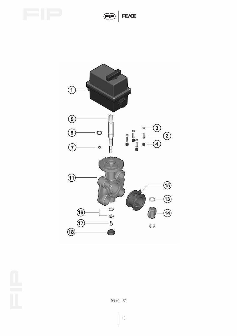
DN 40 ÷ 50
19
FE/CE
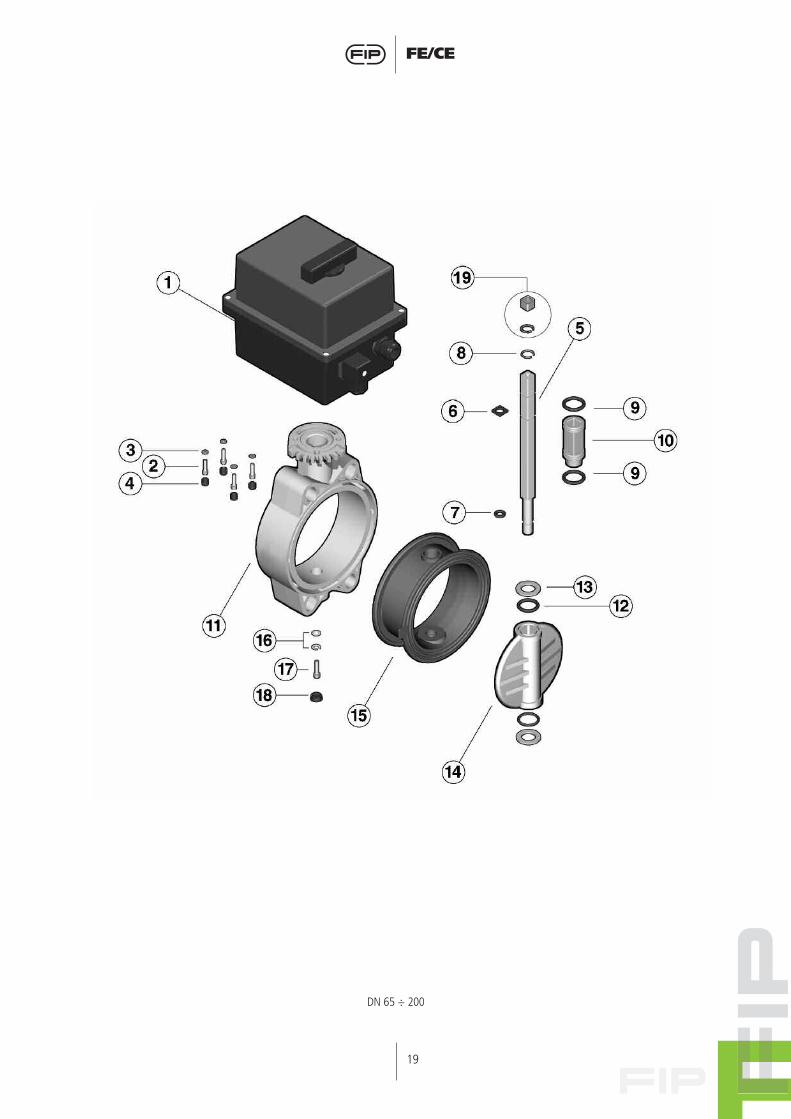
DN 65 ÷ 200
20
FE/CE
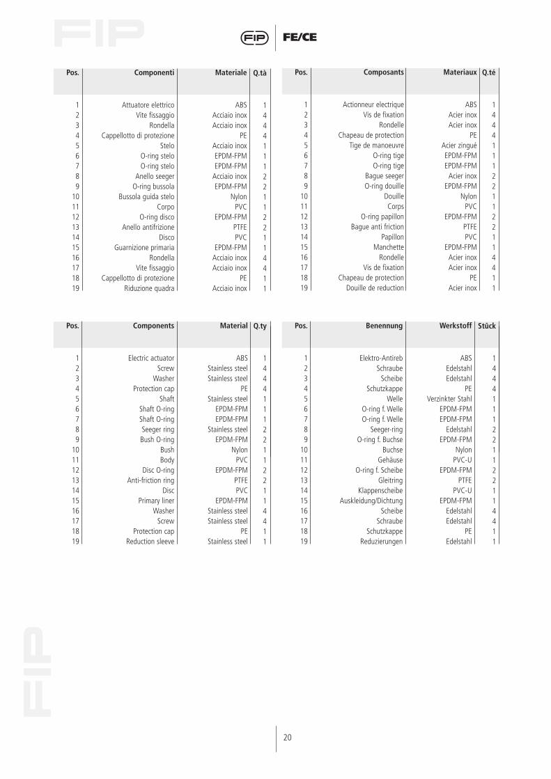
Pos.
123456789
10111213141516171819
Q.tà
1444111221122114411
Componenti
Attuatore elettricoVite fissaggio
RondellaCappellotto di protezione
SteloO-ring steloO-ring stelo
Anello seegerO-ring bussola
Bussola guida steloCorpo
O-ring discoAnello antifrizione
DiscoGuarnizione primaria
RondellaVite fissaggio
Cappellotto di protezioneRiduzione quadra
Materiale
ABSAcciaio inoxAcciaio inox
PEAcciaio inoxEPDM-FPMEPDM-FPM
Acciaio inoxEPDM-FPM
NylonPVC
EPDM-FPMPTFEPVC
EPDM-FPMAcciaio inoxAcciaio inox
PEAcciaio inox
Pos.
123456789
10111213141516171819
Materiaux
ABSAcier inoxAcier inox
PEAcier zinguéEPDM-FPMEPDM-FPM
Acier inoxEPDM-FPM
NylonPVC
EPDM-FPMPTFEPVC
EPDM-FPMAcier inoxAcier inox
PEAcier inox
Q.té
1444111221122114411
Composants
Actionneur electriqueVis de fixation
RondelleChapeau de protection
Tige de manoeuvreO-ring tigeO-ring tige
Bague seegerO-ring douille
DouilleCorps
O-ring papillonBague anti friction
PapillonManchette
RondelleVis de fixation
Chapeau de protectionDouille de reduction
Pos.
123456789
10111213141516171819
Components
Electric actuatorScrew
WasherProtection cap
Shaft Shaft O-ringShaft O-ringSeeger ringBush O-ring
BushBody
Disc O-ringAnti-friction ring
DiscPrimary liner
WasherScrew
Protection capReduction sleeve
Material
ABSStainless steelStainless steel
PEStainless steel
EPDM-FPMEPDM-FPM
Stainless steelEPDM-FPM
NylonPVC
EPDM-FPMPTFEPVC
EPDM-FPMStainless steelStainless steel
PEStainless steel
Pos.
123456789
10111213141516171819
Benennung
Elektro-AntirebSchraube
ScheibeSchutzkappe
WelleO-ring f. WelleO-ring f. Welle
Seeger-ringO-ring f. Buchse
BuchseGehäuse
O-ring f. ScheibeGleitring
KlappenscheibeAuskleidung/Dichtung
ScheibeSchraube
SchutzkappeReduzierungen
Werkstoff
ABSEdelstahlEdelstahl
PEVerzinkter Stahl
EPDM-FPMEPDM-FPM
EdelstahlEPDM-FPM
NylonPVC-U
EPDM-FPMPTFE
PVC-UEPDM-FPM
EdelstahlEdelstahl
PEEdelstahl
Q.ty
1444111221122114411
Stûck
1444111221122114411