FE da INDESIGN copia - Braeco · potabile ed altre sostanze ali-mentari secondo varie norme ed i...
14
1 FE-PVC Valvola a farfalla Butterfly valve Vanne à papillon Absperrklappe • Valvola di intercettazione e regolazione • Gamma dimensionale da DN 40 a DN 200 mm, serie DIN 3202 K2 e ISO 5752 Medium serie 25 • Resistenza a pressioni di eserci- zio fino a 16 bar a 20° C • Materiale corpo e disco: PVC • Sistema di foratura con fori ovali che permette l’accoppiamento secondo numerosi standards internazionali • Versione manuale a leverismo con maniglia in PVC e crema- gliera in PVC • Possibilità di installazione di- retta di riduttore manuale e di servocomandi pneumatici e/o elettrici a foratura standard ISO 5211 F05, F07, F10 • Tenuta primaria intercambiabile con manicotto in elastomero EPDM, FPM, NBR • Possibilità di installazione anche come valvola di fine linea o di scarico di fondo o rapido da serbatoio • Idoneità del PVC impiegato a venire a contatto con acqua potabile ed altre sostanze ali- mentari secondo varie norme ed i regolamenti vigenti • Used for fast control and ON/ OFF operations • Size range: from DN 40 up to DN 200 mm, series DIN 3202 K2 and ISO 5752 Medium se- ries 25 • Working pressure 16 bar at 20° C • One piece body, and disc mate- rial: PVC • Oval holes body to fit with flanges in different standards • Hand operated version with PVC hand lever and PVC ratchet • Possibility to install gear box and actuators directly using standard drilling provided on top of body (ISO 5211 F05, F07, F10) • Interchangeable primary liner in elastomer EPDM, FPM, or NBR. • Possible mounting of valve as end valve, or quick discharge from tanks • FIP PVC is suitable for con- veying foodstuff and drinking water and meets the various standards and regulations • Vanne d’arrêt et de régulation • Gamme dimensionnelle de DN 40 à DN 200 mm, série DIN 3202 K2 et ISO 5752 Medium série 25 • Pression de service jusqu’à 16 bar à 20°C • Matériau corps et papillon: PVC • Système de perçage par trous ovales permettant l’accouple- ment selon plusieurs standard s internationaux • Version manuelle à lévier avec poignée et cremaillère en PVC • Possibilité de montage directe d’un réducteur manuel ou d’actionneurs grace au perçage ISO 5211 F05, F07, F10 du sommet du corps • Manchette interchangeable en élastomère EPDM, FPM, NBR • Possibilité de montage en fin de ligne, ou sur réservoir • PVC de qualité alimentaire apte à l’utilisation avec l’eau potable et les aliments suivant plusieurs normes et réglements en vi- gueur • Geeignet für Drossel- und Absperrfunktionen • Abmessungen von DN 40 bis DN 200 mm, entsprechend DIN 3202 K2 und ISO 5752 Baulänge mittel, Serie 25 • Höchstzulässiger Betriebsdruck 16 bar bei 20° C • Einteiliger Klappenkörper und Klappenscheibe aus PVC-U. • Vier ovale Schraubenlöcher für den Einsatz mit Flanschen nach verschiedenen Normen • Manuelle Ausführung mit er- gonomischem Handhebel aus PVC-U mit Rastung für eine schnelle Durchflußregulierung • Integrierter Adapterflansch, für eine einfache Montage von Handgetriebe oder Antrieb, mit den Anschlußmaßen F 05, F 07, F10 nach ISO 5211 • Der Klappenkörper ist nicht me- diumberührt. Die Auskleidung ist mit der Dichtung kombiniert und auswechselbar, Ausführung in EPDM, FPM oder NBR. • Die Absperrklappe kann auch als Schnellentnahmearmatur, z.B. an Tanks eingesetzt werden. • FIP PVC-U entspricht den gel- tenden Vorschriften und ist für Trinkwasser oder andere für den Verzehr bestimmte Medien zugelassen. PNEUMATIC ACTUATOR GEAR BOX ELECTRIC ACTUATOR HAND LEVER
Transcript of FE da INDESIGN copia - Braeco · potabile ed altre sostanze ali-mentari secondo varie norme ed i...

1
FE-PVC
Valvola a farfalla Butterfly valve Vanne à papillon Absperrklappe
• Valvola di intercettazione e regolazione
• Gamma dimensionale da DN 40 a DN 200 mm, serie DIN 3202 K2 e ISO 5752 Medium serie 25
• Resistenza a pressioni di eserci-zio fino a 16 bar a 20° C
• Materiale corpo e disco: PVC • Sistema di foratura con fori ovali
che permette l’accoppiamento secondo numerosi standards
internazionali• Versione manuale a leverismo
con maniglia in PVC e crema-gliera in PVC
• Possibilità di installazione di-retta di riduttore manuale e di servocomandi pneumatici e/o elettrici a foratura standard ISO 5211 F05, F07, F10
• Tenuta primaria intercambiabile con manicotto in elastomero EPDM, FPM, NBR
• Possibilità di installazione anche come valvola di fine linea o di scarico di fondo o rapido da serbatoio
• Idoneità del PVC impiegato a venire a contatto con acqua potabile ed altre sostanze ali-mentari secondo varie norme ed i regolamenti vigenti
• Used for fast control and ON/OFF operations
• Size range: from DN 40 up to DN 200 mm, series DIN 3202 K2 and ISO 5752 Medium se-ries 25
• Working pressure 16 bar at 20° C• One piece body, and disc mate-
rial: PVC• Oval holes body to fit with
flanges in different standards• Hand operated version with
PVC hand lever and PVC ratchet• Possibility to install gear box
and actuators directly using standard drilling provided on top of body (ISO 5211 F05, F07, F10)
• Interchangeable primary liner in elastomer EPDM, FPM, or NBR.
• Possible mounting of valve as end valve, or quick discharge from tanks
• FIP PVC is suitable for con-veying foodstuff and drinking water and meets the various standards and regulations
• Vanne d’arrêt et de régulation• Gamme dimensionnelle de DN
40 à DN 200 mm, série DIN 3202 K2 et ISO 5752 Medium série 25
• Pression de service jusqu’à 16 bar à 20°C
• Matériau corps et papillon: PVC• Système de perçage par trous
ovales permettant l’accouple-ment selon plusieurs standard s internationaux
• Version manuelle à lévier avec poignée et cremaillère en PVC
• Possibilité de montage directe d’un réducteur manuel ou d’actionneurs grace au perçage ISO 5211 F05, F07, F10 du sommet du corps
• Manchette interchangeable en élastomère EPDM, FPM, NBR
• Possibilité de montage en fin de ligne, ou sur réservoir
• PVC de qualité alimentaire apte à l’utilisation avec l’eau potable et les aliments suivant plusieurs normes et réglements en vi-gueur
• Geeignet für Drossel- und Absperrfunktionen
• Abmessungen von DN 40 bis DN 200 mm, entsprechend DIN 3202 K2 und ISO 5752 Baulänge mittel, Serie 25
• Höchstzulässiger Betriebsdruck 16 bar bei 20° C • Einteiliger Klappenkörper und
Klappenscheibe aus PVC-U. • Vier ovale Schraubenlöcher für
den Einsatz mit Flanschen nach verschiedenen Normen
• Manuelle Ausführung mit er-gonomischem Handhebel aus PVC-U mit Rastung für eine schnelle Durchflußregulierung
• Integrierter Adapterflansch, für eine einfache Montage von Handgetriebe oder Antrieb, mit den Anschlußmaßen F 05, F 07, F10 nach ISO 5211
• Der Klappenkörper ist nicht me-diumberührt. Die Auskleidung ist mit der Dichtung kombiniert und auswechselbar, Ausführung in EPDM, FPM oder NBR.
• Die Absperrklappe kann auch als Schnellentnahmearmatur, z.B. an Tanks eingesetzt werden.
• FIP PVC-U entspricht den gel-tenden Vorschriften und ist für Trinkwasser oder andere für den Verzehr bestimmte Medien zugelassen.
PNEUMATIC ACTUATOR GEAR BOX ELECTRIC ACTUATOR HAND LEVER

2
FE-PVC
LEGENDA
d diametro nominale esterno del tubo in mm
DN diametro nominale interno in mm
PN pressione nominale in bar (pressione max di esercizio a 20° C-acqua)
g peso in grammi
U numero dei fori
s spessore tubo in mm
SDR standard dimension ratio = d/s
PVC cloruro di polivinile rigido
EPDM elastomero etilene propi-lene
FPM fluoroelastomero
NBR elastomero butadiene acrilonitrile
PTFE politetrafluoroetilene
d nominal outside diameter of the pipe in mm
DN nominal internal diameter in mm
PN nominal pressure in bar (max. working pressure
at 20° C - water)
g weight in grams
U number of holes
s wall thickness, mm
SDR standard dimension ratio = d/s
PVC unplasticized polyvinyl chloride
EPDM ethylene propylene rub-ber
FPM vinylidene fluoride rubber
NBR butadiene-acrylonitrile rubber
PTFE polytetrafluoroethylene
d diamètre éxtérieur nominal du tube en mm
DN diamètre nominal interieur en mm
PN pression nominale en bar (pression de service max à 20° C - eau)
g poids en grammes
U nombre de trous
s épaisseur du tube, mm
SDR standard dimension ratio = d/s
PVC polychlorure de vinyle non plastifié
EPDM élastomère ethylène propylène
FPM fluorélastomère de vinylidène
NBR caoutchouc butadiène acrylonitrile
PTFE polytétrafluoroéthylène
d Rohraußendurchmesser in mm
DN Rohrnennweite in mm
PN Nenndruck; höchstzulässiger Betriebsdruck in bar, bei 20° C Wasser
g Gewicht in Gramm
U Anzahl der Schraubenlöcher
s Wandstärke, mm
SDR Standard Dimension Ratio = d/s
PVC-U Polyvinylchlorid hart
EPDM Ethylenpropylen- dienelastomer
FPM Fluorelastomer
NBR Nitrilelastomer
PTFE Polytetraflourethylen
I dati del presente prospetto sono for-niti in buona fede. La FIP non si assu-me alcuna responsabilità su quei dati non direttamente derivati da norme internazionali. La FIP si riserva di ap-portarvi qualsiasi modifica.
The data given in this leaflet are offered in good faith. No liability can be accepted concerning technical data that are not directly covered by reco-gnized international standards. FIP reserves the right to carry out any modification to the products shown in this Ieaflet.
Les données contenues dans cette brochure sont fournies en bonne foi. FIP n’assume aucune responsabilitépour les données qui ne dérivent pas directement des normes internationa-les. FIP garde le droit d’apporter toute modification aux produits présentés dans cette brochure.
Alle Daten dieser Druckschrift wurden nach bestem Wissen angegeben, jedoch besteht keine Verbindlichkeit, sofern sie nicht direkt internationalen Normen entnommen wurden. Die Än-derung von Maßen oder Ausführungen bleibt FIP vorbehalten.
DN 40
DN 50
DN 65
DN 80
DN 10
0DN
125
1000 l/min10000 10000010010
DN 15
0DN
200
bar
1
0,1
0,01
0,001
3
FE-PVC
Dati Tecnici
3
2
4
5
Technical Data
Données Techniques
Technische Daten
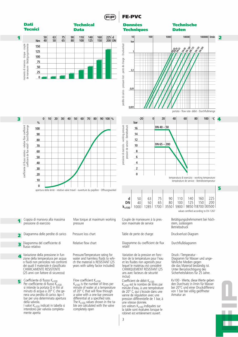
Coppia di manovra alla massima pressione di esercizio
Max torque at maximum working pressure
Couple de manoeuvre à la pres-sion maximale de service
portata - flow rate- débit - Durchflußmenge
apertura della lente - relative valve travel - ouverture du papillon - Offnungswinkel
temperatura di esercizio - working temperaturetempérature de service - Betriebstemperatur
perd
ita d
i car
ico -
pres
sure
lost
- pe
rte d
e ch
arge
- Dr
uckv
erlu
stpr
essio
ne d
i ese
rcizi
o - w
orki
ng p
ress
ure
pres
sion
de s
ervic
e - B
etrie
bsdr
uck
mom
ento
di m
anov
ra -
torq
ue -
coup
le de
man
oeuv
re -
Betä
tigun
gsm
omen
teco
effic
ient
e di
flus
so re
lativ
o - r
elat
ive fl
ow c
oeffi
cient
coef
ficie
nt d
e flu
x re
latif
- Du
rchf
lußm
enge
Betätigungsdrehmoment bei höch-stem, zulässigem Betriebsdruck
values certified according to EN 1267
Diagramma delle perdite di carico Pressure loss chart Table de perte de charge Druckverlust-Diagram
Coefficiente di flusso Kv100Per coefficiente di flusso Kv100si intende la portata Q in litri al minuto di acqua a 20° C che ge-nera una perdita di carico Δp=1 bar per una determinata apertura della valvola.I valori Kv100 indicati in tabella si intendono per valvola completa-mente aperta
Flow coefficient Kv100 Kv100 is the number of litres per minute of water at a temperature of 20° C that will flow through a valve with a one-bar pressure differential at a specified rate. The Kv100 values shown in the ta-ble are calculated with the valve completely open
Coefficient de débit Kv100Kv100 est le nombre de litres par minute d’eau, à une température de 20° C, qui s’écoule dans une vanne de régulation avec une pression différentielle de 1 bar, à une vitesse donnée.Les valeurs Kv100 indiquées sur la table sont évaluées lorsque le robinet est entièrement ouvert
Kv100 - Werte, diese Werte geben den Durchsatz in l/min für Wasser bei 20°C und einer Druckdifferenz von 1 bar bei völlig geöffneter Armatur an
7565
1700
6350
1285
5040
1000
dDN
kv100
9080
3550
110100
5900
140125
9850
225200
30500
160150
18700
1
1
2Diagramma del coefficiente di flusso relativo
Relative flow chart Diagramme du coefficient de flux relatif
Durchflußdiagramm3
Variazione della pressione in fun-zione della temperatura per acqua o fluidi non pericolosi nei confronti dei quali il materiale è classificato CHIMICAMENTE RESISTENTE (25 anni con fattore di sicurezza)
Pressure/Temperature rating for water and harmless fluids to whi-ch the material is RESISTANT (25 years with safety factor included)
Variation de la pression en fonc-tion de la température pour l’eau et les fluides non agressifs pour lequel le matériau est considéré CHIMIQUEMENT RESISTANT (25 ans avec facteurs de sécurité inclus)
Druck / Temperatur - Diagramm für Wasser und unge-fährliche Medien gegen die das Material beständig ist. Unter Berücksichtigung des Sicherheitsfaktors für 25 Jahre.
4
5
Nm
150
125
100
75
50
25
0
dDN
6350
5040
7565
160150
140125
110100
9080
225200
%
100
90
80
70
60
50
40
30
20
10
0
0 10 20 30 %40 10050 60 70 80 90bar
16
14
12
10
8
6
4
2
0
-20 0 20 40 °C60 10080
DN 40 ÷ 50
DN 65 ÷ 200
4
FE-PVC
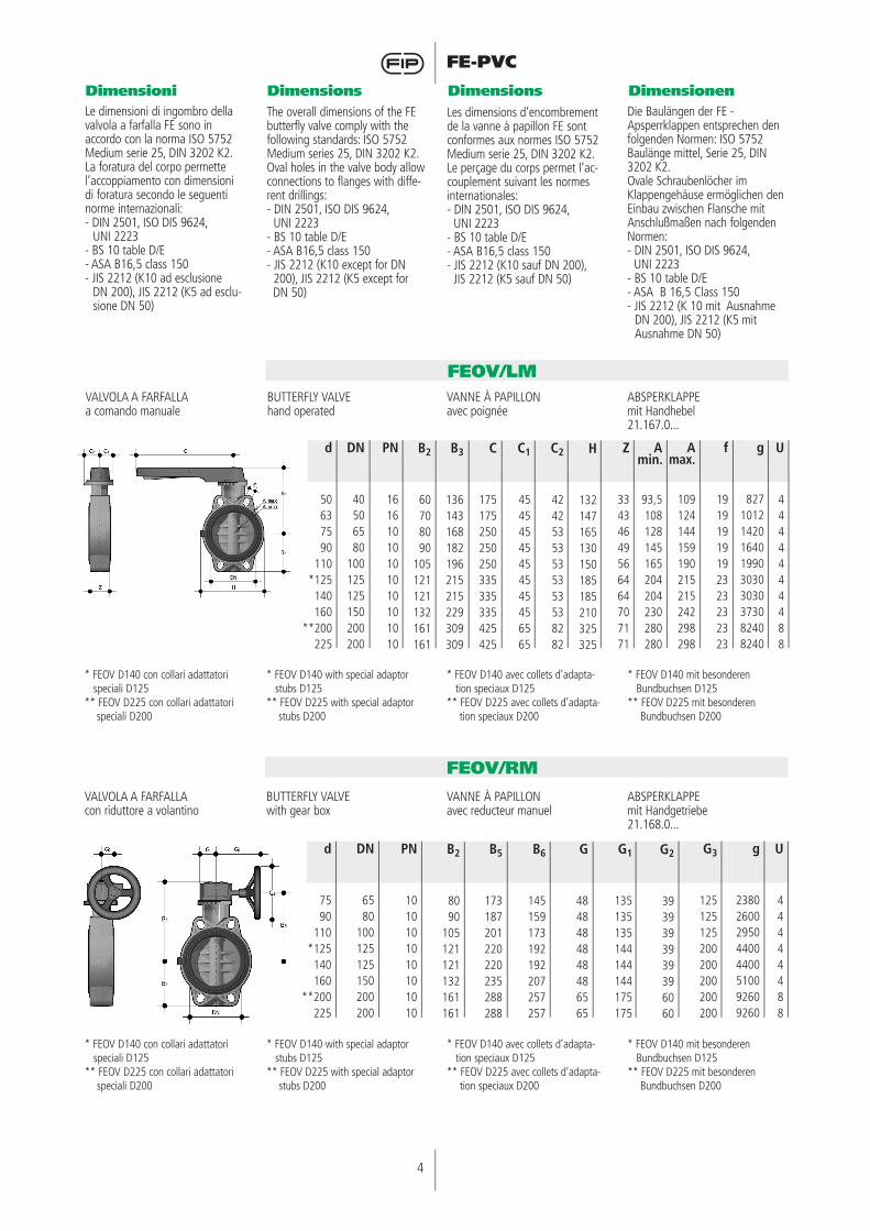
VALVOLA A FARFALLAa comando manuale
BUTTERFLY VALVEhand operated
VANNE À PAPILLONavec poignée
ABSPERKLAPPEmit Handhebel21.167.0...
* FEOV D140 con collari adattatori speciali D125** FEOV D225 con collari adattatori speciali D200
* FEOV D140 with special adaptor stubs D125** FEOV D225 with special adaptor stubs D200
* FEOV D140 avec collets d’adapta-tion speciaux D125
** FEOV D225 avec collets d’adapta-tion speciaux D200
* FEOV D140 mit besonderen Bundbuchsen D125
** FEOV D225 mit besonderen Bundbuchsen D200
Dimensioni Dimensions Dimensions Dimensionen
FEOV/LM
Le dimensioni di ingombro della valvola a farfalla FE sono in accordo con la norma ISO 5752 Medium serie 25, DIN 3202 K2.La foratura del corpo permette l’accoppiamento con dimensioni di foratura secondo le seguenti norme internazionali: - DIN 2501, ISO DIS 9624, UNI 2223- BS 10 table D/E- ASA B16,5 class 150- JIS 2212 (K10 ad esclusione DN 200), JIS 2212 (K5 ad esclu-
sione DN 50)
The overall dimensions of the FE butterfly valve comply with the following standards: ISO 5752 Medium series 25, DIN 3202 K2.Oval holes in the valve body allow connections to flanges with diffe-rent drillings:- DIN 2501, ISO DIS 9624, UNI 2223- BS 10 table D/E- ASA B16,5 class 150- JIS 2212 (K10 except for DN 200), JIS 2212 (K5 except for DN 50)
Les dimensions d’encombrement de la vanne à papillon FE sont conformes aux normes ISO 5752 Medium serie 25, DIN 3202 K2.Le perçage du corps permet l’ac-couplement suivant les normes internationales:- DIN 2501, ISO DIS 9624, UNI 2223- BS 10 table D/E- ASA B16,5 class 150- JIS 2212 (K10 sauf DN 200), JIS 2212 (K5 sauf DN 50)
Die Baulängen der FE - Apsperrklappen entsprechen den folgenden Normen: ISO 5752 Baulänge mittel, Serie 25, DIN 3202 K2.Ovale Schraubenlöcher im Klappengehäuse ermöglichen den Einbau zwischen Flansche mit Anschlußmaßen nach folgenden Normen:- DIN 2501, ISO DIS 9624, UNI 2223- BS 10 table D/E- ASA B 16,5 Class 150- JIS 2212 (K 10 mit Ausnahme
DN 200), JIS 2212 (K5 mit Ausnahme DN 50)
d
50637590
110*125140160
**200225
B2
60708090
105121121132161161
B3
136143168182196215215229309309
C
175175250250250335335335425425
C1
45454545454545456565
C2
42425353535353538282
PN
16161010101010101010
DN
40506580
100125125150200200
H
132147165130150185185210325325
Z
33434649566464707171
Amin.
93,5108128145165204204230280280
Amax.
109124144159190215215242298298
f
19191919192323232323
g
827101214201640199030303030373082408240
U
4444444488
VALVOLA A FARFALLAcon riduttore a volantino
BUTTERFLY VALVEwith gear box
VANNE À PAPILLONavec reducteur manuel
ABSPERKLAPPEmit Handgetriebe21.168.0...
FEOV/RM
d
7590
110*125140160
**200225
B2
8090
105121121132161161
B5
173187201220220235288288
B6
145159173192192207257257
G
4848484848486565
G1
135135135144144144175175
PN
1010101010101010
DN
6580
100125125150200200
G2
3939393939396060
G3
125125125200200200200200
g
23802600295044004400510092609260
U
44444488

5
FE-PVC
Accessori Accessories Accessoires Zubehor
Gamma dimensionale: DN 40-200 mmStandard: ISO-DINPN: 6-4 bar con acqua a 20° C (utilizzate come fine linea).Sono disponibili inserti filettati per trasformare tutte le valvole a farfalla in PVC della serie FEOV in valvole a corpo Lug.Gli inserti in acciaio zincato sono facilmente montabili prima dell’installazione della valvola sul-l’impianto e consentono l’utilizzo della stessa come valvole di fine linea a flangia singola in totale sicurezza.Le valvole a farfalla Lug sono di tipo unidirezionale ogni qualvolta vengano usate per servizio di fine linea con flangiatura singola o per elemento di scollegamento per operazioni di manutenzione senza drenaggio delle linee.
Range: DN 40-200 mmStandard: ISO-DINPN: 6-4 bar with water at 20° C (used as end of line).Lug threaded inserts are available to transform the FEOV butterfly valve in LUG type. The zinc plated steel Lug inserts are field instal-lable and they allow easy single side installation to mating flange.The Lug type FEOV butterfly valves with single mating flange installation are unidirectional, whenever used for dead end service, including service line disconnection under pressure for maintenance operations.
Gamme dimensionelle: DN 40-200 mmStandard: ISO-DINPN: 6-4 bar avec eau à 20° C (utilisé en fin de ligne).Toutes le vannes à papillon en PVC peuvent etre transformées en vannes au corps LUG par des in-serts se placent simplement avant le montage de la vanne en fin de ligne en totale securité.Les vannes à papillon au corps LUG déviennent monodirectionel-les quand elle sont utilisée en fin de ligne où comme elément de séparation pour effectuer la ma-nutention sans vider la ligne.
Abmessungen: DN 40-200 mmStandard: ISO-DIN oder ANSIPN: 10 bar mit Wasser bei 20° C (benutzt als Leitungsende).Alle FE Klappen Können Lug Ausführung werden: die verzink-ten Einsätze können einfach an der Klappe montiert sein.Die Lug Einsätze erlauben die direkte Montage der Bolzen im FE Körper, so kann diese Klappe als Leitungsende angewendet wer-den. Während der Wartung kann die Stromabflansche demontiert werden und die Rohrleitung unter Druck bleiben.MERKE: Diese Klappen sind einsinning, wenn sie als Leitungsende benutzt werden.
125106
DNPN (1)
PN LUG (2)
65106
50166
40166
80106
100106
150104
200104
FE LUG INSERT
(1) Installazione con doppia flangia(2) Installazione con flangia singola
(1) Double mating flange installation(2) Single mating flange installation
(1) Montage avec double bride folle(2) Montage avec une bride folle
(1) Installation mit doppelter Flansche(2) Installation mit einzelner Flansche

6
FE-PVC
Il kit RF maniglia di regolazione fine permette, quando montato sulla FE, di effettuare una rego-lazione accurata della portata di fluido attraverso la valvola con-sentendo il bloccaggio del disco in una posizione qualunque tra 0° (chiuso) e 90° (aperto).
The infinite adjusting RF handle kit allows, when mounted on the FE, to do an accurate adjusting of flow rate through the valve.The RF kit allows to fix the disc position wherever in between the 0° (close position) and the 90° (open position).
Le kit RF pour la régulation de la poignée, permets de effectuer une regulation des litres par minute des liquides qui s’écoulent dans une vanne en permettant le blo-cage du disc entre une position quelconque de 0° (fermé) a 90° (ouvert)
Die stufenlose Feineinstellung RF, wenn auf der FE montiert, erlaubt eine präzise Fluss Regelung durch die Absperrklappe.Das RF Kit erlaubt das Positionieren der Scheibe in jeder Stellung zwischen 0° und 90°.
Pos.
123456789
10
Componenti
PiattelloViteVite
DistanzialeManigliaRondella
ViteTappino
RondellaManopola
Q.tà
1211111111
Materiale
Acciaio inoxAcciaio inoxAcciaio inox
PVCPVC
Acciaio inoxAcciaio inox
PEAcciaio inox
PP
Pos.
123456789
10
Composants
PlateauVisVis
EntretoisePoignée
RondelleVis
Bouchon de protectionRondelle
Bouton
Q.té
1211111111
Materiaux
Acier inoxAcier inoxAcier inox
PVCPVC
Acier inoxAcier inox
PEAcier inox
PP
Pos.
123456789
10
Components
PadScrewScrew
SpacerMandleWasher
ScrewCap
WasherThumb Knob
Q.ty
1211111111
Material
Stainless SteelStainless SteelStainless Steel
PVCPVC
Stainless SteelStainless Steel
PEStainless Steel
PP
Pos.
123456789
10
Benennung
RastplatteSchraubeSchraube
DistanzstückHandhebel
ScheibeSchraube
SchutztopfenScheibe
Drehknopf
Menge
1211111111
Werkstoff
EdelstahlEdelstahlEdelstahl
PVC-UPVC-U
EdelstahlEdelstahl
PEEdelstahl
PP
FE RF

7
FE-PVC
* Momento di serraggio per ottenere la tenuta in prova idraulica
(1,5 x PN a 20° C) (bulloneria nuova o lubrificata)
* Torque required for watertight joints (1,5 x PN at 20° C)
(new or lubricated bolts)
* Couple de serrage pour obtenir l’étanchéité en test hydraulique
(1,5 x PN à 20° C) (boulons neufs ou lubrifiés)
* Anzugsdrehmoment für Druckproben (1,5 x PN bei 20° C),
bei neuen oder gefetteten Schrauben
Automatismi Actuators Automatismes Antriebe
Dimensioni dei bulloni da utilizzare nell’installazione
Dimensions of the bolts to be used in installation
Dimensions des boulons à utiliser pour l’installation
Schraubenabmessungen zum Einbau zwischen Flanschen
La valvola può essere fornita, a richiesta, completa di servoco-mandi. Esiste comunque la pos-sibilità di applicare direttamente attuatori pneumatici e/o elettrici standard e riduttori a volantino per operazioni gravose, grazie alla torretta in PVC riproducente la dima di foratura prevista dalla norma ISO 5211, F05, F07 e F10.
The valve can be supplied with actuators on request. Capability of using standard pneumatic or electric actuators, or reduction gears, installed directly on inte-grally moulded PVC mounting pad, drilled according to ISO 5211, F05 , F07 and F10.
Sur demande, la vanne peut être fournie avec des servomoteurs. Il est possible de monter directe-ment des actionneurs pneuma-tiques et/ou électriques et des réducteurs à volant pour alléger la manoeuvre, grace au perçage de la platine suivant la norme ISO 5211, F05, F07 et F10.
Auf Anfrage können die Armaturen komplett mit Antrieben geliefert werden. Der Aufbau von standardisierten Schneckenradgetrieben, Elektro - oder Pneumatik -Antrieben erfolgt direkt auf den integrierten Adapterflansch, der nach ISO 5211, F05, F07 und F10 gebohrt ist.
d
50637590
110140160225
DN
40506580
100125150200
J
77
7 / 99999
11
P
5050
50 / 7070707070
102
F 05F 05
F 05 / F 07F 07F 07F 07F 07F 10
T
1212121616191924
Q
1111111414171722
d
50637590
110140160225
DN
50636580
100125150200
L min
M16x150M16x150M16x170M16x180M16x180M16x210M20x240M20x260
*Nm
912151820354055
8
FE-PVC
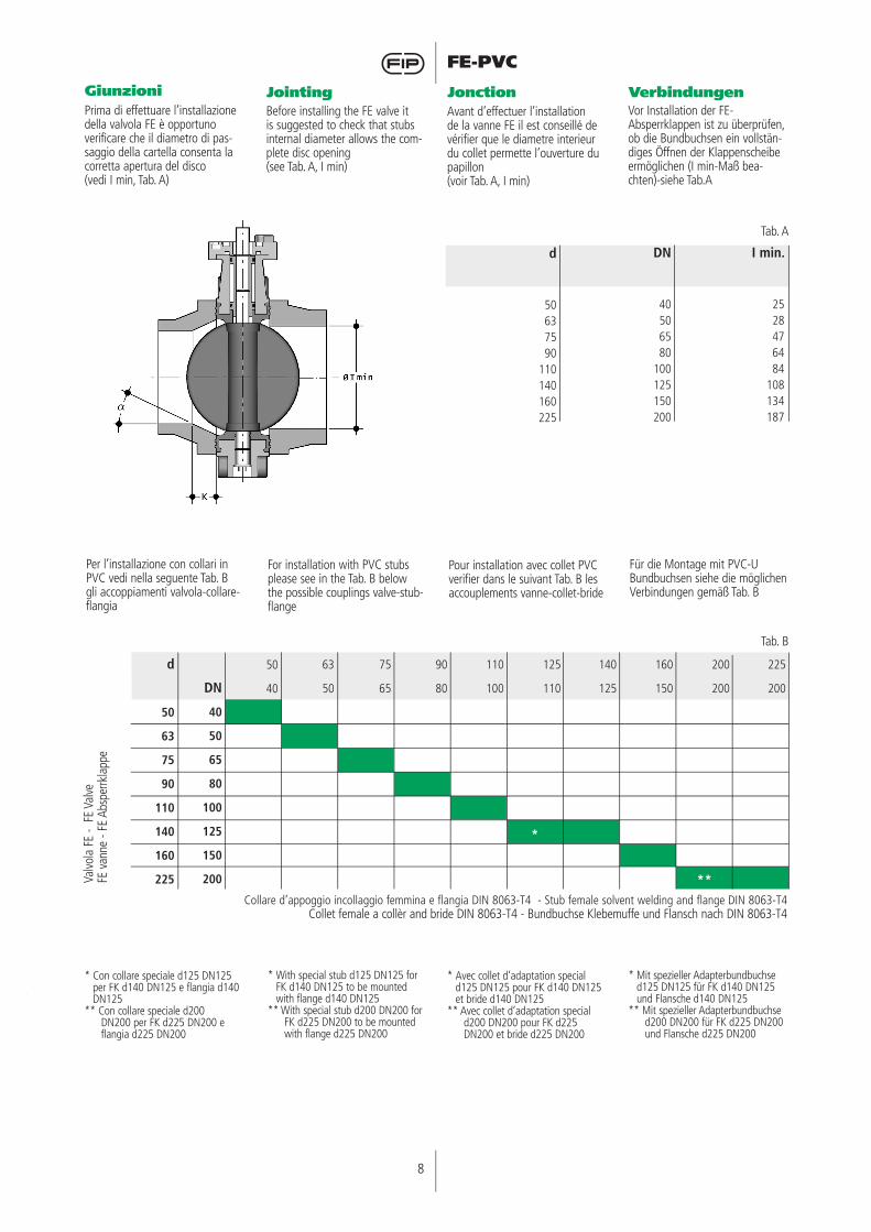
Giunzioni Jointing Jonction VerbindungenPrima di effettuare l’installazione della valvola FE è opportuno verificare che il diametro di pas-saggio della cartella consenta la corretta apertura del disco (vedi I min, Tab. A)
Before installing the FE valve it is suggested to check that stubs internal diameter allows the com-plete disc opening (see Tab. A, I min)
Avant d’effectuer l’installation de la vanne FE il est conseillé de vérifier que le diametre interieur du collet permette l’ouverture du papillon(voir Tab. A, I min)
Vor Installation der FE-Absperrklappen ist zu überprüfen, ob die Bundbuchsen ein vollstän-diges Öffnen der Klappenscheibe ermöglichen (I min-Maß bea-chten)-siehe Tab.A
Per l’installazione con collari in PVC vedi nella seguente Tab. B gli accoppiamenti valvola-collare-flangia
For installation with PVC stubs please see in the Tab. B below the possible couplings valve-stub-flange
Pour installation avec collet PVC verifier dans le suivant Tab. B les accouplements vanne-collet-bride
Für die Montage mit PVC-U Bundbuchsen siehe die möglichen Verbindungen gemäß Tab. B
Collare d’appoggio incollaggio femmina e flangia DIN 8063-T4 - Stub female solvent welding and flange DIN 8063-T4Collet female a collèr and bride DIN 8063-T4 - Bundbuchse Klebemuffe und Flansch nach DIN 8063-T4
d
50637590
110140160225
DN
40506580
100125150200
I min.
2528476484
108134187
* Con collare speciale d125 DN125 per FK d140 DN125 e flangia d140 DN125
** Con collare speciale d200 DN200 per FK d225 DN200 e flangia d225 DN200
* With special stub d125 DN125 for FK d140 DN125 to be mounted with flange d140 DN125
** With special stub d200 DN200 for FK d225 DN200 to be mounted with flange d225 DN200
* Avec collet d’adaptation special d125 DN125 pour FK d140 DN125 et bride d140 DN125
** Avec collet d’adaptation special d200 DN200 pour FK d225 DN200 et bride d225 DN200
* Mit spezieller Adapterbundbuchse d125 DN125 für FK d140 DN125 und Flansche d140 DN125
** Mit spezieller Adapterbundbuchse d200 DN200 für FK d225 DN200 und Flansche d225 DN200
d
50
63
75
90
110
140
160
225
50
40
63
50
75
65
90
80
110
100
125
110
*
140
125
160
150
200
200
**
225
200DN
40
50
65
80
100
125
150
200Valvo
la F
E -
FE V
alve
FE v
anne
- FE
Abs
perrk
lapp
e
Tab. B
Tab. A

9
FE-PVC
Per l’installazione di cartelle PP-PE, per saldatura testa a testa co-dolo corto o elettrofusione/testa a testa codolo lungo, verificare gli accoppiamenti valvola-cartella-flangia e le quote K - a di smus-satura ove necessario a seconda delle diverse SDR. (Tab. C)
For installation of PP-PE stubs, butt welding short or electrofusion/butt welding long, please verify the valve-stub-flange combination and the chamfering K - a dimensions, where according the SDR is necessary. (Tab. C)
Pour installation de PP-PE, coller bout a bout court or electrofusion/bout à bout longue, verifier les accouplements vanne-collet-bride et les cùtes de cham-freinage K - a si nécessaire selon le SDR. (Tab. C)
In PE bzw. PP-Rohrleitungen ist der Innendurchmesser abhängig von SDR-Klasse. Für wenige, in der Tab. C definierte, Abmessungen müssen sowohl bei langen als auch kurzen Vorschweißbunde diese mecha-nisch bearbeitet werden (Winkel und k-Maß beachten), oder andersweitige Voraussetzungen für ein vollständiges Öffnen der Klappenscheibe geschaffen wer-den (z.B. Distanzscheiben).
k=35a=20°
k=10a=35°
k=15a=35°
k=20a=30°
k=30a=30°
k=40a=15°k=35
a=30°
k=35a=25°
k=35a=20°
k=40a=20°
k=15a=35°
Cartella codolo corto/lungo DIN16962/16963 e flangia - Stubflanges short/long DIN16962/16963 and flangeCollet court/lounge DIN16962/16963 et bride - Vorschweissbunde, kurze oder oder lange Form nach DIN16962/16963 mit Losflanschen
d
50
63
75
90
110
140
160
225
50
40
63
50
75
65
90
80
110
100
125
110
140
125
160
150
180
150
200
200
225
200DN
40
50
65
80
100
125
150
200
17/17,6
11
7,4
Valvo
la F
E -
FE V
alve
FE v
anne
- FE
Abs
perrk
lapp
eSD
R
Tab. C
10
FE-PVC
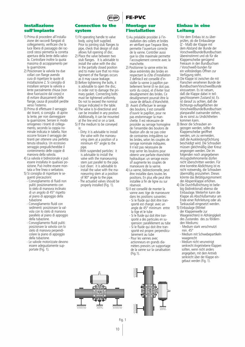
Installazione sull’impianto
Connection to the system
Montage sur l’installation
Einbau in eine Leitung
1) Prima di procedere all’installa-zione dei raccordi flangiati di collegamento, verificare che la luce libera di passaggio dei rac-cordi stessi permetta la corretta apertura della lente della valvo-la. Controllare inoltre la quota massima di accoppiamento per la guarnizione.
2) Posizionare la valvola tra due collari con flange avendo cura di rispettare le quote di installazione Z. Si consiglia di installare sempre la valvola a lente parzialmente chiusa (non deve fuoriuscire dal corpo) e di evitare disassamenti delle flange, causa di possibili perdite verso l’esterno.
3) Prima di effettuare il serraggio dei tiranti, si consiglia di aprire la lente, per non danneggiare la guarnizione. Serrare in modo omogeneo i tiranti di collega-mento, secondo la coppia no-minale indicata in tabella. Non occorre forzare il serraggio dei tiranti per ottenere una perfetta tenuta idraulica. Un eccessivo serraggio pregiudicherebbe il contenimento delle coppie di manovra della valvola.
4) La valvola è bidirezionale e può essere installata in qualsiasi po-sizione. Può inoltre essere mon-tata a fine linea o serbatoio.
5) Si consiglia di rispettare le se-guenti precauzioni: - Convogliamento di fluidi non
puliti: posizionamento con lo stelo di manovra inclinato di un angolo di 45° rispetto al piano di appoggio della tubazione
- Convogliamento fluidi con sedimenti: posizionare la val-vola con lo stelo di manovra parallelo al piano di appoggio della tubazione.
- Convogliamento fluidi puliti: posizionare la valvola con lo stelo di manovra perpendi-colare la piano di appoggio della tubazione.
- Le valvole motorizzate devono essere adeguatamente sup-portate (Fig. 1).
1) Fit operating handle to valve body, using bolt supplied.
Prior to jointing stub flanges to pipe, check that design of stub allows full opening of disc.
2) Place the valve between two stub flanges. It is advisable to install the valve with the disc in the partially closed position and to make sure that no misa-lignment of the flanges occurs as it may cause leakage.
3) Before tightening the bolts, it is advisable to open the disc, in order not to damage the pri-mary gasket. Connecting bolts must be tightened uniformly. Do not to exceed the nominal torque indicated in the table.
4) The valve is bi-directional and can be installed in any position. Additionally, it can be mounted at the line end or on a tank.
5) If the medium to be conveyed is:- Dirty: it is advisable to install
the valve with the manoeu-vring stem at a position of a minimum 45° angle to the pipe.
- With suspended particles: it is advisable to install the valve with the manoeuvring stem just parallel to the pipe.
- Just clean: it is advisable to install the valve with the ma-noeuvring stem at a position of 90° angle to the pipe.
- The actuated valves should be properly installed (Fig. 1).
1) Au préalable procéder à l’in-stallation des collets et brides en vérifiant que l’espace libre, permette l’ouverture correcte de la vanne. Contrôler aussi que la côte maximale permette l’accouplement correcte avec la manchette.
2) Positionner la vanne entre les deux extrémités des brides en respectant la cÙte d’installation Z definie.Il est conseillé d’in-staller la vanne à papillon par-tiellement fermé (il ne doit pas sortir du corps), et d’éviter tout desalignement des brides. Ce desalignement pourrait être la cause de défauts d’étanchéité.
3) Avant d’effectuer le serrage des boulons, il est conseillé d’ouvrir le papillon, pour ne pas endommager la man-chette. Il est nécessaire de procéder au serrage homogène de l’ensemble des boulons de fixation afin de ne pas créer de contraintes irrégulières sur les brides, selon les couples de serrage nominale indiquées. Il n’est pas nécessaire de trop serrer les boulons pour obtenir une parfaite étanchéité hydraulique: un serrage exces-sif augmente les couples de manoeuvre de la vanne.
4) La vanne, bidirectionnelle, peut être installée dans toutes les positions. En plus elle peut être installée à fin de ligne ou sur réservoir.
5) Il est conseillé de monter la vanne avec tige de manoeuvre dans les positions suivantes:- Si le fluide qui doit être tran-sporté est chargé: avec un angle de 45° minimum entre la tige et le tube
- Si le fluide qui doit être tran-sporté a des particules en su-spension: parallélement au tube
- Si le fluide qui doit être tran-sporté est propre: perpendicu-lairement au tube
- Pour les vannes avec actionneurs en grands dia-
mèters prevoirs un supportage de la vanne sur la canalisation (Fig.1).
1) Vor dem Einbau ist zu über-prüfen, ob die Einbaulänge (Z - Maß) der Klappe mit dem Abstand der Bunde der Vorschweißbunde/Bundbuchsen übereinstimmt und ob für die Klappenscheibe genügend Freiraum in den Bundbuchsen / Vorschweiß-bunden für ein vollständiges Öffnen zur Verfügung steht.
2) Die Klappe ist zwischen die mit Flanschen versehenen Bunde der Bundbuchsen/Vorschweißbunde einzusetzen. Es ist ratsam, daß die Klappe dabei in teil-geschlossenem Zustand ist. Es ist darauf zu achten, daß die Dichtungs-auflageflächen der Vorschweißbunde/Bundbuchsen planparallel zueinander stehen, da es sonst zu Undichtheiten kommen kann.
3) Bevor die Schrauben an-gezogen werden, sollte die Klappenscheibe geöffnet werden, um zu vermeiden, daß die Auskleidung/Dichtung beschädigt wird. Die Schrauben müssen gleichmäßig über Kreuz angezogen werden. Die im folgenden noch angegebenen Anzugsdrehmomente dürfen nicht überschritten werden. Für eine korrekte Abdichtung ist es nicht notwendig, die Schrauben übermäßig anzuziehen. Dieses könnte das Betätigungsmoment der Absperrklappe erhöhen.
4) Die Durchflußrichtung ist belie-big (bidirektional) ebenso die Einbaulage. Weiterhin kann die Klappe als Abschlußarmatur am Ende einer Rohrleitung oder als Tankauslaß eingesetzt werden.
5) Einbaulage (Winkel der Klappenwelle zur Waagerechten) in Abhängigkeit des Zustandes des zu fördern-den Mediums:- Medium stark verschmutzt min. 45°
- Medium mit Schwebepartikeln waagerecht
- Medium nicht verunreinigt senkrecht Angetriebene Klappen sollten, wenn nicht anders angegeben, mit dem Antrieb senkrecht über der Klappe ein-gebaut werden (Fig. 1).
Fig. 1
11
FE-PVC
- Ein schnelles Schließen von Armaturen ist zu vermeiden, um Druckstöße die durch Wasserschläge entstehen, zu verhindern. Rohrsysteme können hierdurch zerstört werden. Aus diesem Grunde sollten Schneckenradgetriebe installiert werden, die auf Anfrage lieferbar sind.
6) Für die Montage ist es empfeh-lenswert die Gummidichtungen mit Öl oder Fett zu schmieren, wobei keine Mineralölprodukte zur Anwendung kommen dürfen, da hierdurch die Dichtungen angegriffen wer-den können.
- Evitare sempre brusche mano-vre di chiusura e proteggere la valvola da manovre acciden-tali. A tale scopo si consiglia di prevedere l’installazione di riduttori di manovra, fornibili su richiesta.
6) Nelle operazioni di montaggio è consigliabile lubrificare le guar-nizioni di tenuta in gomma con oli o grassi idonei (sono sconsi-gliati gli oli minerali in quanto aggrediscono la gomma etilene - propilene)
- It is important to avoid rapid closure of valves to eliminate the possibility of water ham-mer causing damage to the pipe.
- Pneumatic actuators must be fitted with exhaust restrictors.
6) During assembly it is advisable to lubricate the rubber seals. (Do not use mineral oils on EPDM).
- Il est important d’éviter toujours de fermetures trop rapides des vannes. A ce but il est conseillé de prévoir l’installation de réducteurs de manoeuvre.
6) Dans les opérations de monta-ge, nous conseillons de lubrifier les joints avec de l’huile. A ce propos, il ne faut jamais employer des huiles minérales, agressives pour le caoutchouc en éthylène propylène.
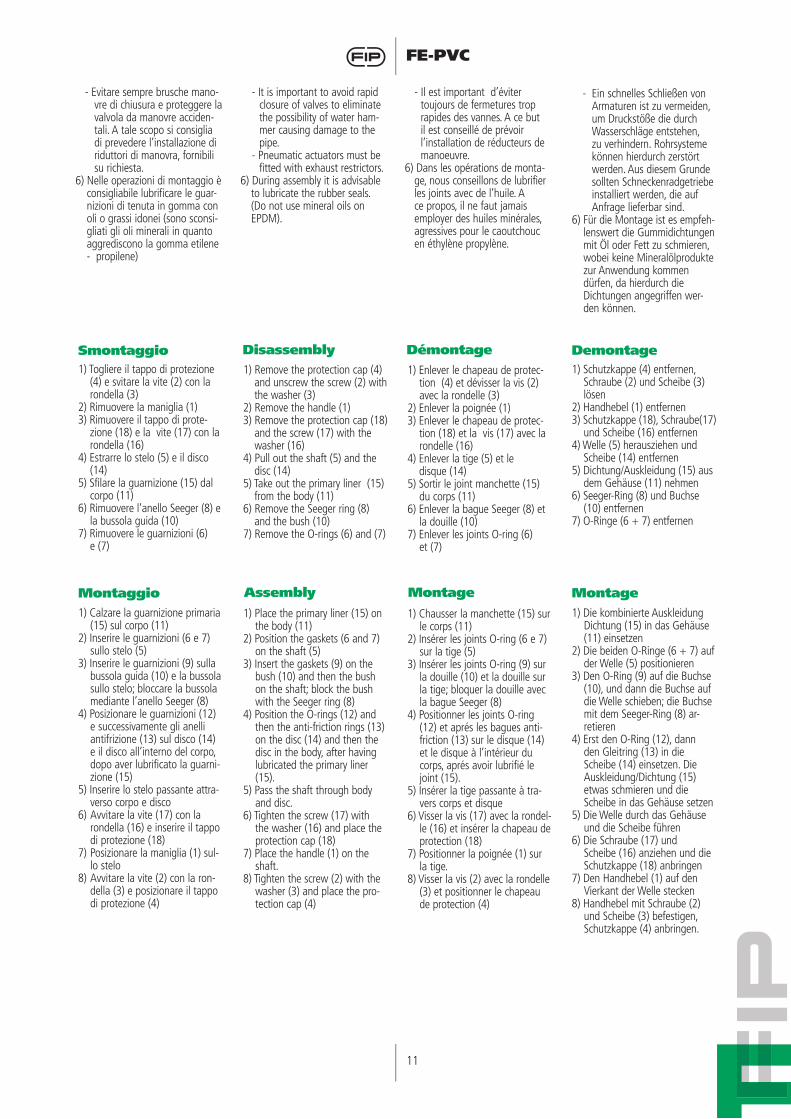
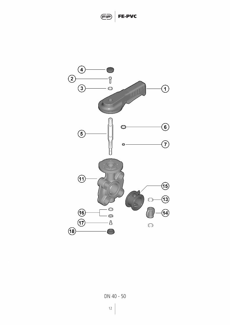
1) Togliere il tappo di protezione (4) e svitare la vite (2) con la rondella (3)
2) Rimuovere la maniglia (1)3) Rimuovere il tappo di prote-
zione (18) e la vite (17) con la rondella (16)
4) Estrarre lo stelo (5) e il disco (14)
5) Sfilare la guarnizione (15) dal corpo (11)
6) Rimuovere l’anello Seeger (8) e la bussola guida (10)
7) Rimuovere le guarnizioni (6) e (7)
1) Remove the protection cap (4) and unscrew the screw (2) with the washer (3)
2) Remove the handle (1)3) Remove the protection cap (18)
and the screw (17) with the washer (16)
4) Pull out the shaft (5) and the disc (14)
5) Take out the primary liner (15) from the body (11)
6) Remove the Seeger ring (8) and the bush (10)
7) Remove the O-rings (6) and (7)
1) Enlever le chapeau de protec-tion (4) et dévisser la vis (2) avec la rondelle (3)
2) Enlever la poignée (1)3) Enlever le chapeau de protec-
tion (18) et la vis (17) avec la rondelle (16)
4) Enlever la tige (5) et le disque (14)5) Sortir le joint manchette (15)
du corps (11)6) Enlever la bague Seeger (8) et
la douille (10)7) Enlever les joints O-ring (6)
et (7)
1) Schutzkappe (4) entfernen, Schraube (2) und Scheibe (3) lösen
2) Handhebel (1) entfernen3) Schutzkappe (18), Schraube(17)
und Scheibe (16) entfernen4) Welle (5) herausziehen und
Scheibe (14) entfernen5) Dichtung/Auskleidung (15) aus
dem Gehäuse (11) nehmen6) Seeger-Ring (8) und Buchse
(10) entfernen7) O-Ringe (6 + 7) entfernen
Smontaggio Disassembly Démontage Demontage
Montaggio Assembly Montage Montage1) Calzare la guarnizione primaria
(15) sul corpo (11)2) Inserire le guarnizioni (6 e 7)
sullo stelo (5) 3) Inserire le guarnizioni (9) sulla
bussola guida (10) e la bussola sullo stelo; bloccare la bussola mediante l’anello Seeger (8)
4) Posizionare le guarnizioni (12) e successivamente gli anelli antifrizione (13) sul disco (14) e il disco all’interno del corpo, dopo aver lubrificato la guarni-zione (15)
5) Inserire lo stelo passante attra-verso corpo e disco
6) Avvitare la vite (17) con la rondella (16) e inserire il tappo di protezione (18)
7) Posizionare la maniglia (1) sul-lo stelo
8) Avvitare la vite (2) con la ron-della (3) e posizionare il tappo di protezione (4)
1) Place the primary liner (15) on the body (11)
2) Position the gaskets (6 and 7) on the shaft (5)
3) Insert the gaskets (9) on the bush (10) and then the bush on the shaft; block the bush with the Seeger ring (8)
4) Position the O-rings (12) and then the anti-friction rings (13) on the disc (14) and then the disc in the body, after having lubricated the primary liner (15).
5) Pass the shaft through body and disc.
6) Tighten the screw (17) with the washer (16) and place the protection cap (18)
7) Place the handle (1) on the shaft.
8) Tighten the screw (2) with the washer (3) and place the pro-tection cap (4)
1) Chausser la manchette (15) sur le corps (11)
2) Insérer les joints O-ring (6 e 7) sur la tige (5)
3) Insérer les joints O-ring (9) sur la douille (10) et la douille sur la tige; bloquer la douille avec la bague Seeger (8)
4) Positionner les joints O-ring (12) et aprés les bagues anti-friction (13) sur le disque (14) et le disque à l’intérieur du corps, aprés avoir lubrifié le joint (15).
5) Insérer la tige passante à tra-vers corps et disque
6) Visser la vis (17) avec la rondel-le (16) et insérer la chapeau de protection (18)
7) Positionner la poignée (1) sur la tige.
8) Visser la vis (2) avec la rondelle (3) et positionner le chapeau de protection (4)
1) Die kombinierte Auskleidung Dichtung (15) in das Gehäuse (11) einsetzen
2) Die beiden O-Ringe (6 + 7) auf der Welle (5) positionieren
3) Den O-Ring (9) auf die Buchse (10), und dann die Buchse auf die Welle schieben; die Buchse mit dem Seeger-Ring (8) ar-retieren
4) Erst den O-Ring (12), dann den Gleitring (13) in die Scheibe (14) einsetzen. Die Auskleidung/Dichtung (15) etwas schmieren und die Scheibe in das Gehäuse setzen
5) Die Welle durch das Gehäuse und die Scheibe führen
6) Die Schraube (17) und Scheibe (16) anziehen und die Schutzkappe (18) anbringen
7) Den Handhebel (1) auf den Vierkant der Welle stecken
8) Handhebel mit Schraube (2) und Scheibe (3) befestigen, Schutzkappe (4) anbringen.
12
FE-PVC
DN 40 - 50
13
FE-PVC
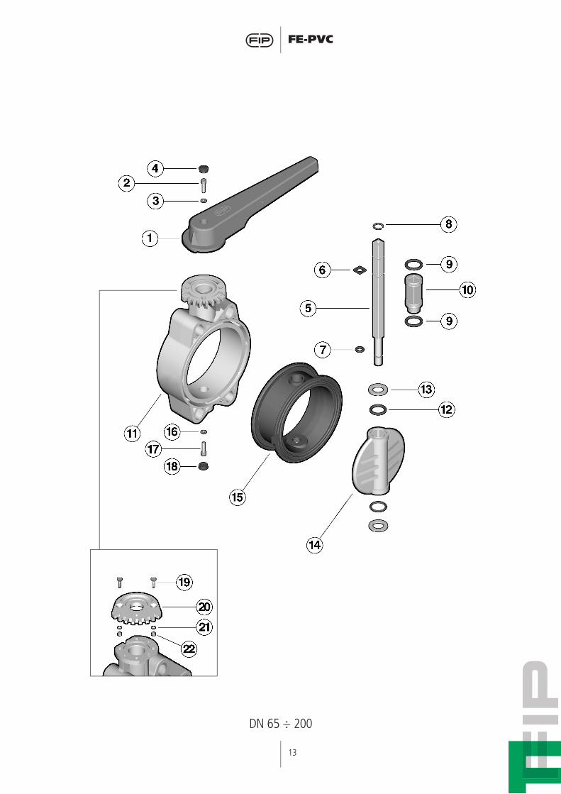
DN 65 ÷ 200

14
FE-PVC
Pos.
123456789
10111213141516171819202122
Componenti
ManigliaVite
RondellaCappellotto di protezione
SteloO-ring steloO-ring stelo
Anello Seeger O-ring bussola
BussolaCorpo
O-ring discoAnello antifrizione
DiscoGuarnizione primaria
RondellaVite
Cappellotto di protezioneVite
PiattelloRondella
Dado
Q.tà
1111111121122111112122
Materiale
PVCAcciaio inoxAcciaio inox
PEAcciaio zincato
EPDM o FPMEPDM o FPMAcciaio inox
EPDM o FPMNylon
PVCEPDM o FPM
PTFEPVC
EPDM o FPMAcciaio
Acciaio inoxPE
Acciaio inoxPVC
Acciaio inoxAcciaio inox
Pos.
123456789
10111213141516171819202122
Composants
PoignéeVis
RondelleChapeau de protection
TigeO-ring tigeO-ring-tige
Bague SeegerO-ring douille
DouilleCorps
O-ring papillonBague anti-friction
PapillonManchette
RondelleVis
Chapeau de protectionVis
PlateauRondelle
Ecrou
Q.té
1111111121122111112122
Materiaux
PVCAcier inoxAcier inox
PEAcier zingué
EPDM ou FPMEPDM ou FPM
Acier inoxEPDM ou FPM
NylonPVC
EPDM ou FPMPTFEPVC
EPDM ou FPMAcier
Acier inoxPE
Acier inoxPVC
Acier inoxAcier inox
Pos.
123456789
10111213141516171819202122
Components
HandleScrew
WasherProtection cap
ShaftShaft O-ringShaft O-ringSeeger ringBush O-ring
BushBody
Disc O-ringAnti-friction ring
DiscPrimary liner
WasherScrew
Protection capScrew
PadWasher
Nut
Q.ty
1111111121122111112122
Material
PVCStainless steelStainless steel
PEZincplated steel
EPDM or FPMEPDM or FPMStainless steelEPDM or FPM
NylonPVC
EPDM or FPMPTFEPVC
EPDM or FPMStainless steelStainless steel
PEStainless steel
PVCStainless steelStainless steel
Pos.
123456789
10111213141516171819202122
Benennung
HandhebelSchraube
ScheibeSchutzkappe
WelleO-Ring f. WelleO-Ring f. Welle
Seeger RingO-Ring f. Buchse
BuchseGehäuse
O-Ring f. ScheibeGleitringScheibe
Dichtung/AuskleidungScheibe
SchraubeSchutzkappe
SchraubeRastplatte
ScheibeMutter
Menge
1111111121122111112122
Werkstoff
PVC-UEdelstahlEdelstahl
PEverzinkter StahlEPDM od. FPMEPDM od. FPM
EdelstahlEPDM od. FPM
NylonPVC-U
EPDM od. FPMPTFE
PVC-UEPDM od. FPM
EdelstahlEdelstahl
PEEdelstahl
PVC-UEdelstahlEdelstahl