¢«°¯²â€°°°±â‚¬°°±â€±â€±â€¹²â€ ±â€°°°»°´°°±’ °¾±â‚¬±â€°°°»±â€¹²â€œ±â€¹¢»
Upload
celeste-martyCategory
view
25download
0description
“emittance”Frank Zimmermann
LTC – Chamonix@CERN
Many thanks to: Ilya Agapov, Gianluigi Arduini, Ralph Assmann, Elena
Benedetto, Enrico Bravin, Oliver Bruning, Helmut Burkhardt, Fritz Caspers, Bernd Dehning, Massimo Giovannozzi, Steve Hutchins, Rhodri Jones, Verena Kain, Thibaut Lefevre, Alick MacPherson, Laurette
Ponce, Rogelio Tomas, Jan Uythoven
Extended
topics
• transverse target emittance• measuring LHC beam emittances • transfer line to LHC matching• minimizing emittance blow up during injection, ramp, and squeeze• longitudinal emittance

transverse target emittance
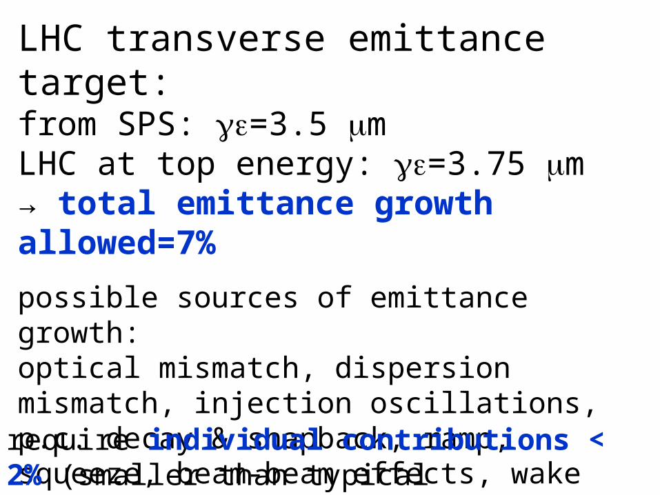
LHC transverse emittance target: from SPS: =3.5 mLHC at top energy: =3.75 m→ total emittance growth allowed=7%
possible sources of emittance growth:optical mismatch, dispersion mismatch, injection oscillations, p.c. decay & snapback, ramp, squeeze, beam-beam effects, wake fields, instabilities, damper noise, rf noise, damper noise, intrabeam scattering, residual-gas scattering, electron cloud,…
require individual contributions < 2% (smaller than typical measurement resolution)
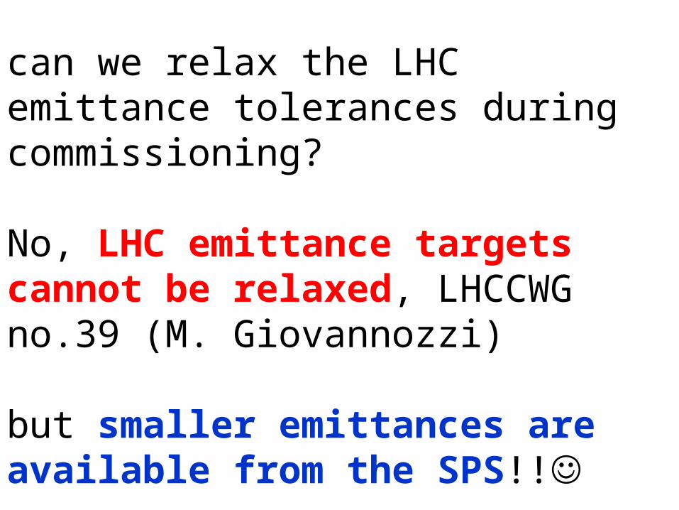
can we relax the LHC emittance tolerances during commissioning?
No, LHC emittance targets cannot be relaxed, LHCCWG no.39 (M. Giovannozzi)
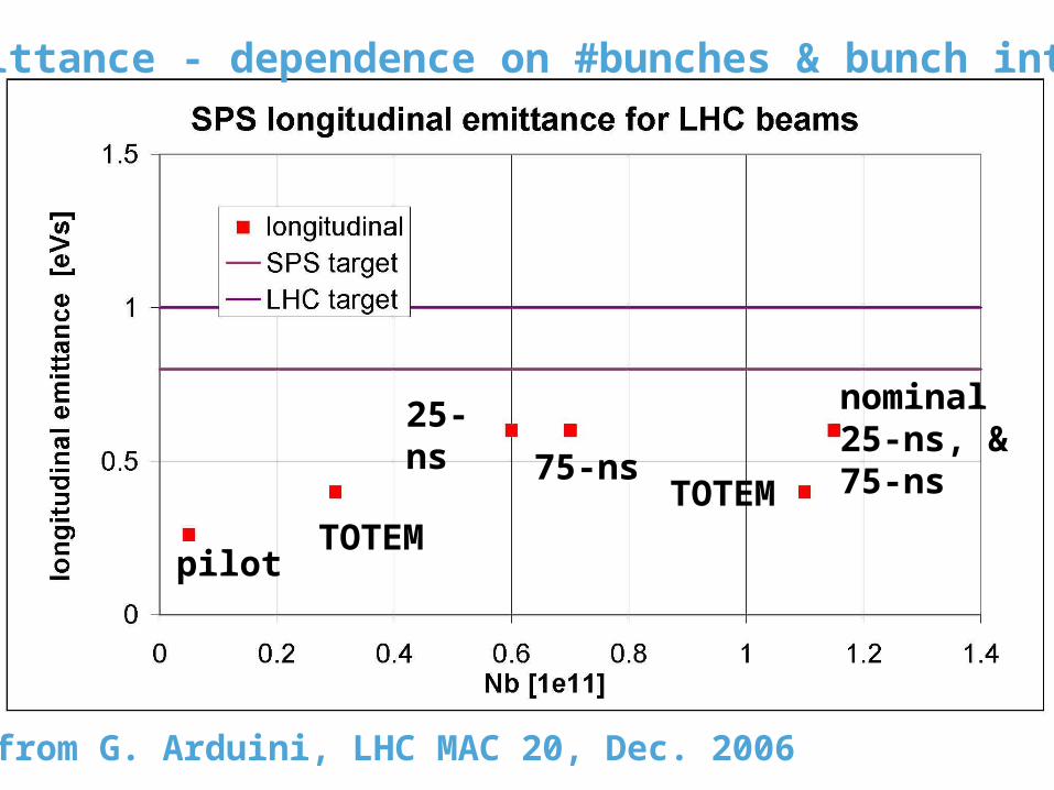
but smaller emittances are available from the SPS!!
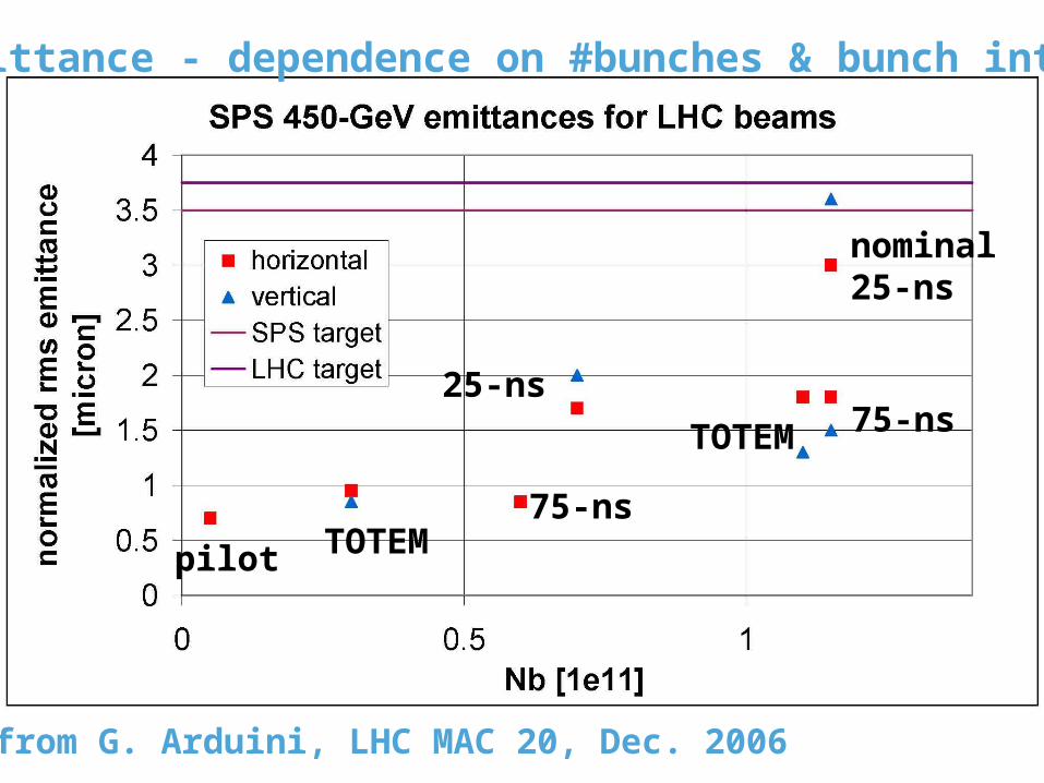
TOTEM 75-ns
nominal25-ns
25-ns
75-nsTOTEMpilot
data from G. Arduini, LHC MAC 20, Dec. 2006
SPS emittance - dependence on #bunches & bunch intensity

proposed strategy:
blow up every beam to the design emittance of 3.5 micron in the SPS with “pink noise” injection into the transverse damper before extracting to the LHC
if the additional LHC emittance increase is found to be too large, we can then reduce the TFB-noise blow up in the SPS until LHC target emittances are obtained
measuring LHC beam emittances

transverse beam-size diagnostics
• 1-pass OTR screens for transfer lines & injection• OTR screen matching monitors• wire scanners • synchrotron light monitors • ionization profile monitor• collimator scans• Schottky monitors
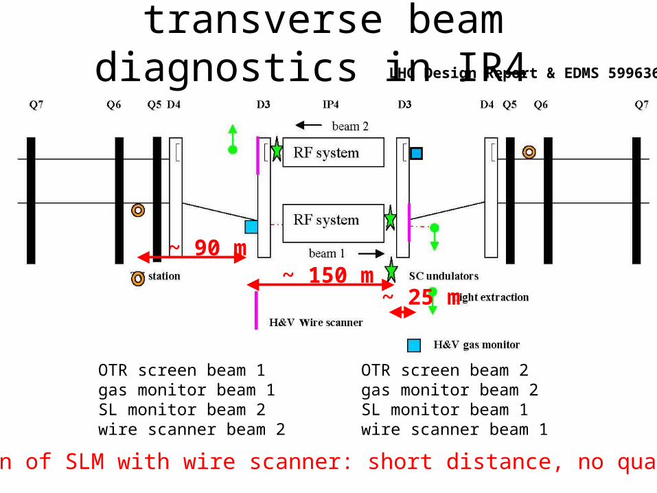
transverse beam diagnostics in IR4
OTR screen beam 1gas monitor beam 1SL monitor beam 2wire scanner beam 2
OTR screen beam 2gas monitor beam 2SL monitor beam 1wire scanner beam 1
~ 90 m~ 150 m
~ 25 m
calibration of SLM with wire scanner: short distance, no quadrupoles
LHC Design Report & EDMS 599636
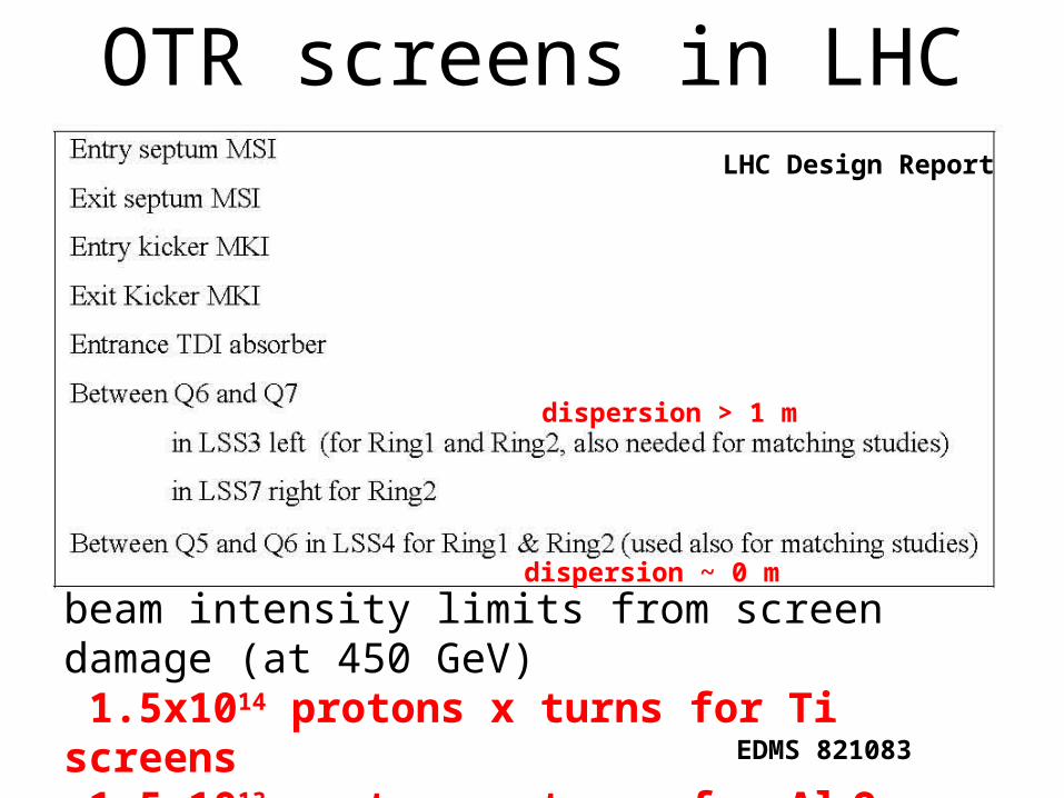
OTR screens in LHCLHC Design Report
dispersion > 1 m
dispersion ~ 0 m
beam intensity limits from screen damage (at 450 GeV) 1.5x10¹⁴ protons x turns for Ti screens 1.5x10¹³ protons x turns for Al2O3 screens
EDMS 821083

wire scannersbeam intensity limits 450 GeV : 25 % of nominal limit for wire damage, quench level limit much higher 7 TeV: limited by both quench and damage of wire 5 % of nominal for quench 7 % of nominal for wire damage
(B. Dehning)
emittance increase due to single wire scan:SPS at 26 GeV: ~0.05 m (14%) SPS at 450 GeV: negligible (a few 1e-5)(F. Roncarolo and B. Dehning, CERN-AB-2005-042 )
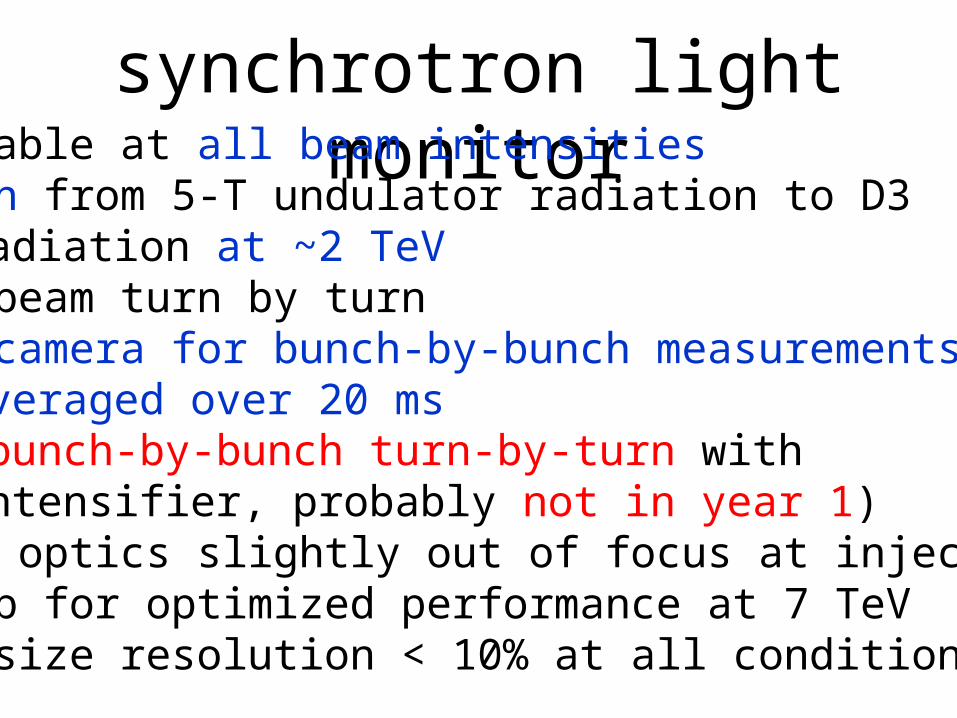
synchrotron light monitoravailable at all beam intensitiesswitch from 5-T undulator radiation to D3
radiation at ~2 TeVfull beam turn by turnfast camera for bunch-by-bunch measurements
averaged over 20 ms(bunch-by-bunch turn-by-turn with intensifier, probably not in year 1)
light optics slightly out of focus at injection set up for optimized performance at 7 TeVbeam-size resolution < 10% at all conditions
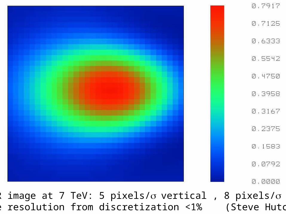
expected SR image at 7 TeV: 5 pixels/vertical , 8 pixels/ horizontal→ emittance resolution from discretization <1% (Steve Hutchins)
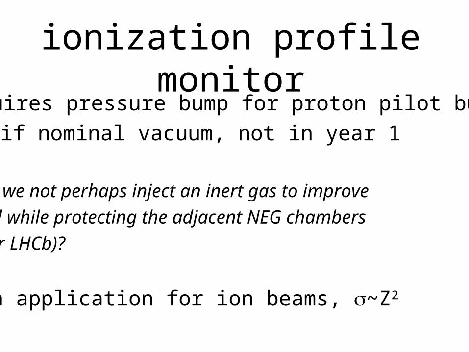
ionization profile monitor
requires pressure bump for proton pilot bunch
if nominal vacuum, not in year 1
could we not perhaps inject an inert gas to improve
signal while protecting the adjacent NEG chambers
(as for LHCb)?
main application for ion beams, ~Z2
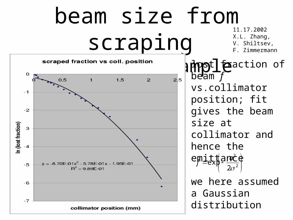
beam size from scraping Tevatron example
2
2
2exp
a
f
lost fraction of beam f vs.collimator position; fit gives the beam size at collimator and hence the emittance
we here assumed a Gaussian distribution
alternatively we can reconstruct the shape
11.17.2002X.L. Zhang,V. Shiltsev,F. Zimmermann

LHC “collimator calibration”
- +
x1x2
Measurehalf gap
Scraper
Collimator Get beam offset from measured jaw positions
R. Assmann, LHCCWG no 5, May 2006
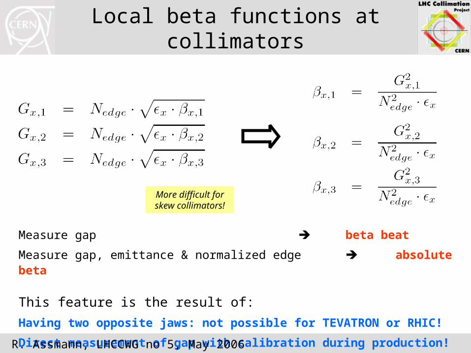
Local beta functions at collimators
Measure gap beta beat
Measure gap, emittance & normalized edge absolute beta
This feature is the result of:
Having two opposite jaws: not possible for TEVATRON or RHIC!
Direct measurement of gap with calibration during production!
More difficult for skew collimators!
R. Assmann, LHCCWG no 5, May 2006
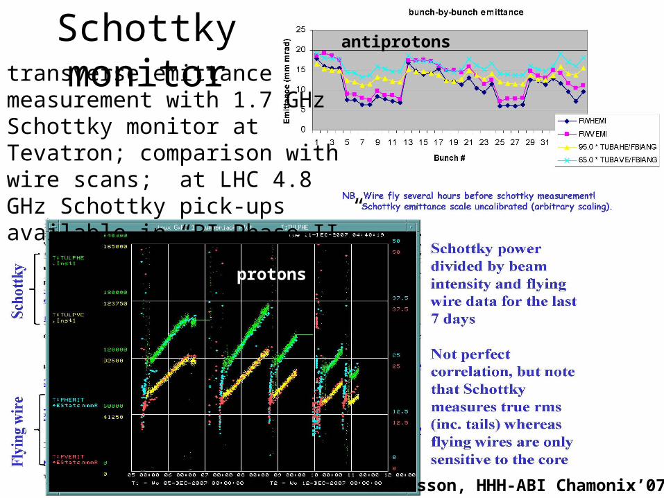
transverse emittancemeasurement with 1.7 GHzSchottky monitor at Tevatron; comparison with wire scans; at LHC 4.8 GHz Schottky pick-upsavailable in “BI Phase-II”
A.Jansson, HHH-ABI Chamonix’07
protons
antiprotonsSchottky monitor
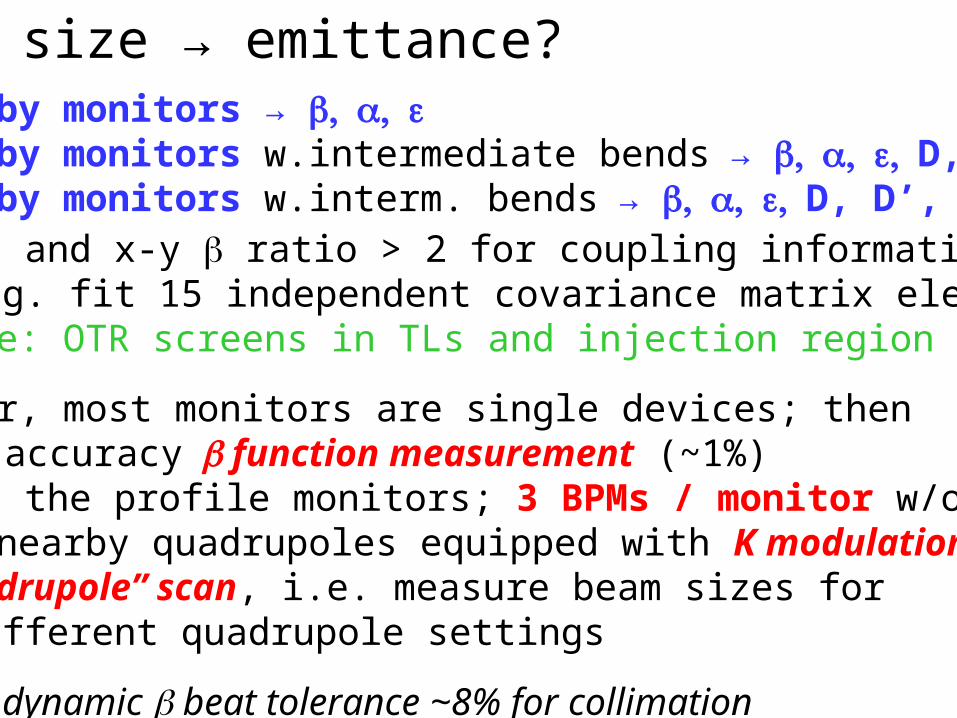
beam size → emittance?3 nearby monitors → 5 nearby monitors w.intermediate bends→ D, D’6 nearby monitors w.interm. bends→ D, D’, rms
[+ and x-y ratio > 2 for coupling information;e.g. fit 15 independent covariance matrix elements]
example: OTR screens in TLs and injection region
however, most monitors are single devices; then high-accuracy function measurement (~1%)
at the profile monitors; 3 BPMs / monitor w/o quad - two nearby quadrupoles equipped with K modulation- “quadrupole” scan, i.e. measure beam sizes for
different quadrupole settings
beware: dynamic beat tolerance ~8% for collimation
transfer line to LHC matching
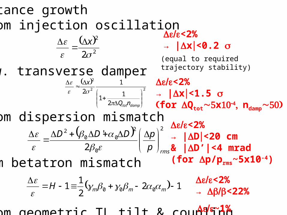
emittance growth- from injection oscillation
w. transverse damper
- from dispersion mismatch
-from betatron mismatch
- from geometric TL tilt & coupling
2
2
2 x
2
0
2
002
2
'
rmsp
pDDD
122
11 000
mmmH
<2%
→ <22%
<2% → |D<20 cm& |D’|<4 mrad(for p/prms~5x10-4)
<2% → |x<0.2
(equal to required trajectory stability)
22
2
21
1
1
2
damptotnQ
x
<2%
→ |x<1.5 forQtotxndamp
~1%
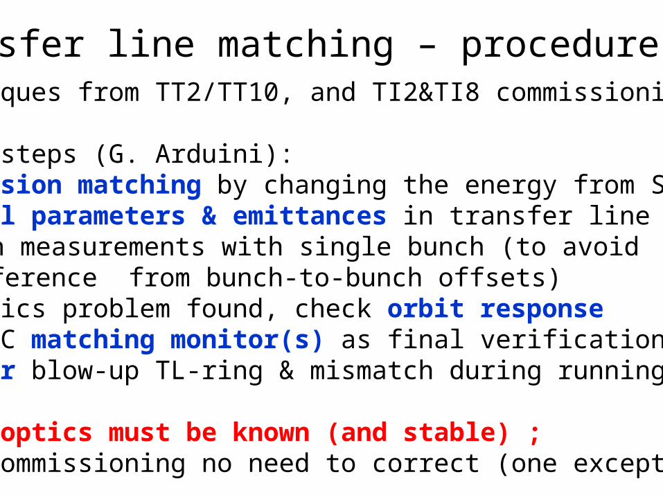
use techniques from TT2/TT10, and TI2&TI8 commissioning
suggested steps (G. Arduini): (1) dispersion matching by changing the energy from SPS(2) optical parameters & emittances in transfer line (screens);
screen measurements with single bunch (to avoid interference from bunch-to-bunch offsets)
(3) if optics problem found, check orbit response(4) use LHC matching monitor(s) as final verification(5) monitor blow-up TL-ring & mismatch during running
note: LHC optics must be known (and stable) ;in TI2/8 commissioning no need to correct (one exception)
transfer line matching – procedure
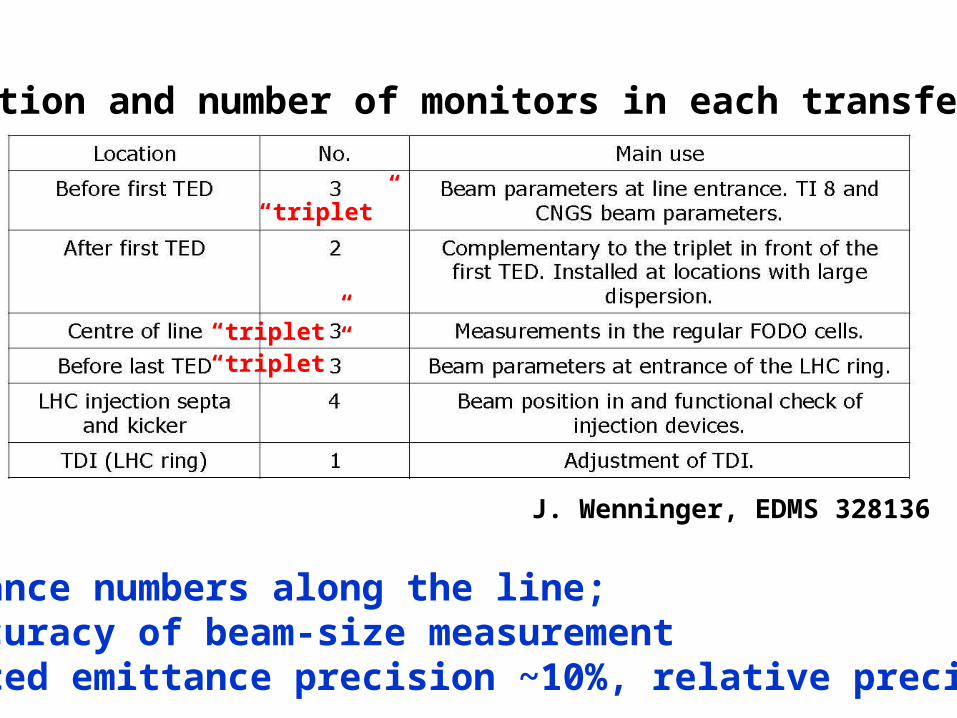
distribution and number of monitors in each transfer line
“triplet”
“triplet”“triplet”
3 emittance numbers along the line;4-5% accuracy of beam-size measurement→ expected emittance precision ~10%, relative precision ~5%
J. Wenninger, EDMS 328136

TI2 dispersion match
J. Uythoven LTC, 5.12.07

J. Uythoven LTC, 5.12.07
TI2 off-line match
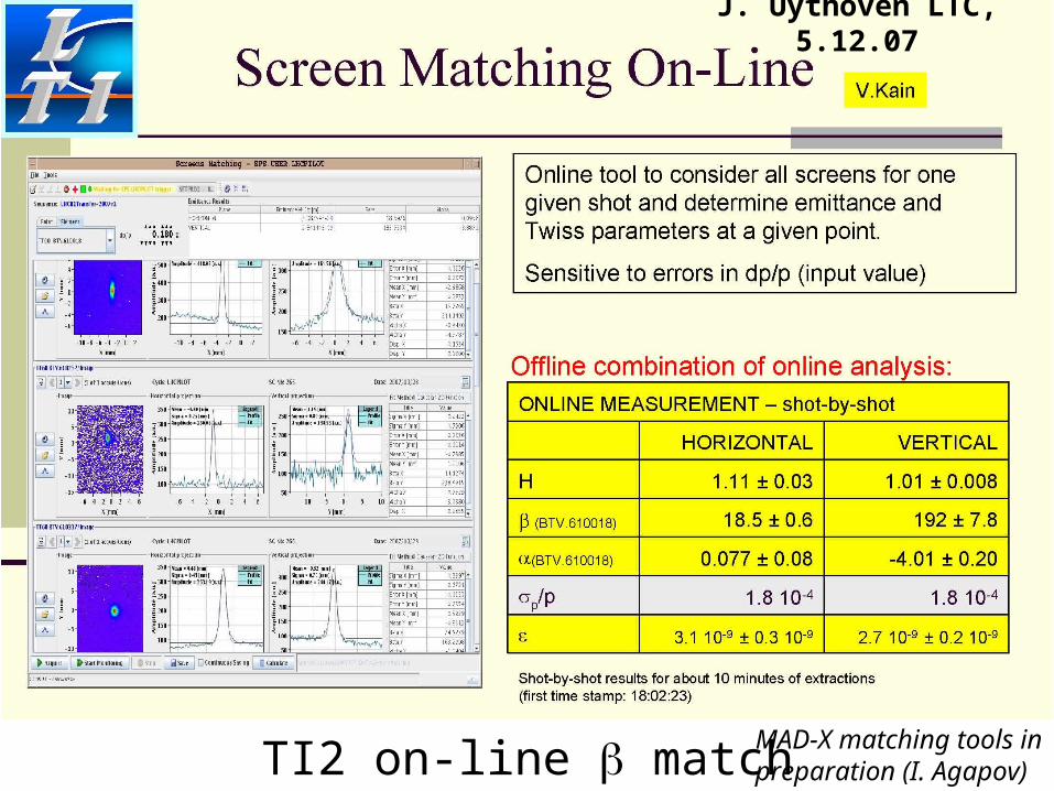
TI2 on-line match
J. Uythoven LTC, 5.12.07
MAD-X matching tools inpreparation (I. Agapov)

TI2 Twiss measurementsFrom: 19:12:28 to 19:28:43 (during dispersion measurements)
PRELIMINARY RESULTSElena Benedetto
Hx Hy
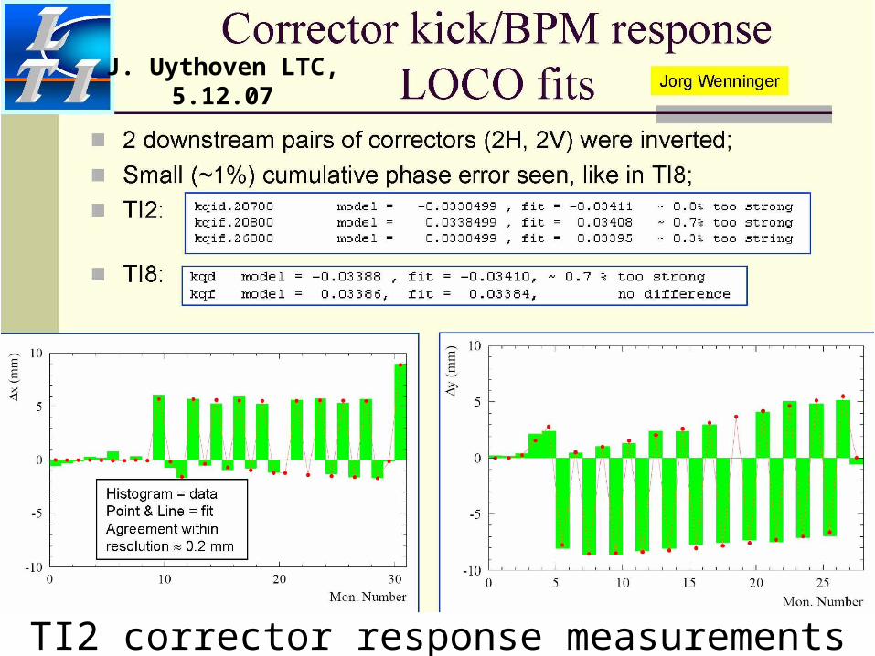
TI2 corrector response measurements
J. Uythoven LTC, 5.12.07
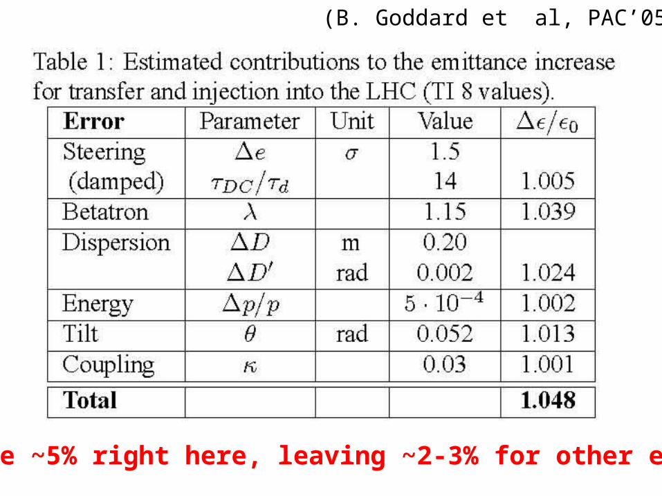
we have ~5% right here, leaving ~2-3% for other effects
(B. Goddard et al, PAC’05)

possible sources of injection errorserrors & changes can arise in SPS, LHC, or transfer line;examples: magnetic stray field at extraction kicker ripple transfer line optics errors (energy error,
misalignments, magnet calibration, ) optics errors in the LHC tune changes in the SPS or LHC * changes in IP2 or 8 at injection changes of crossing angle / separation bump
configuration & spectrometer polarity changes
(H. Burkhardt, Chamonix XIV)

A. Koschik et al, EPAC’06
• LHC aperture at injection is tight • transfer line optics strongly constrained by phase advance relations
between transfer line collimator • 20% change in can change phase advance between TCDIs by 15o &
reduce protected aperture by 10% (H. Burkhardt, Chamonix XIV)• dispersion matching on “cm” level using orbit bumps in the LHC not
practical (A. Koschik et al, EPAC’06)

Matching monitor
Expected resolution ~1%!! EDMS 328146
One fast camera is available, which has to be positioned at the chosen matching screen. The camera is radiation sensitive and needs to be taken out of the tunnel after the measurements.
From year 2, also SLM (& IPM) with fast camera & intensifier might detect mismatch
(B. Dehning)
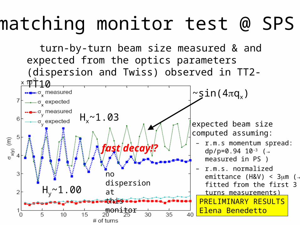
turn-by-turn beam size measured & and expected from the optics parameters (dispersion and Twiss) observed in TT2-TT10
expected beam size computed assuming:
– r.m.s momentum spread: dp/p=0.94 10-3 (→ measured in PS )
– r.m.s. normalized emittance (H&V) < 3m (→ fitted from the first 3 turns measurements)
matching monitor test @ SPS
~sin(4qx)
Hx~1.03
nodispersion atthis monitor
fast decay!?
PRELIMINARY RESULTSElena Benedetto
Hy~1.00
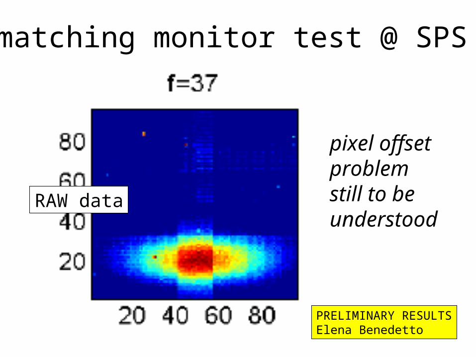
RAW data
matching monitor test @ SPS
pixel offset problemstill to beunderstood
PRELIMINARY RESULTSElena Benedetto
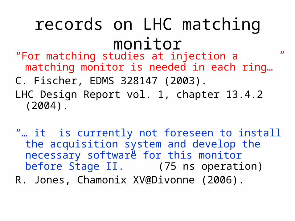
records on LHC matching monitor“For matching studies at injection a matching monitor
is needed in each ring…”C. Fischer, EDMS 328147 (2003).LHC Design Report vol. 1, chapter 13.4.2 (2004).
“… it is currently not foreseen to install the acquisition system and develop the necessary software for this monitor before Stage II.”
(75 ns operation)R. Jones, Chamonix XV@Divonne (2006).
minimizing emittance blow up during injection, ramp, and
squeeze
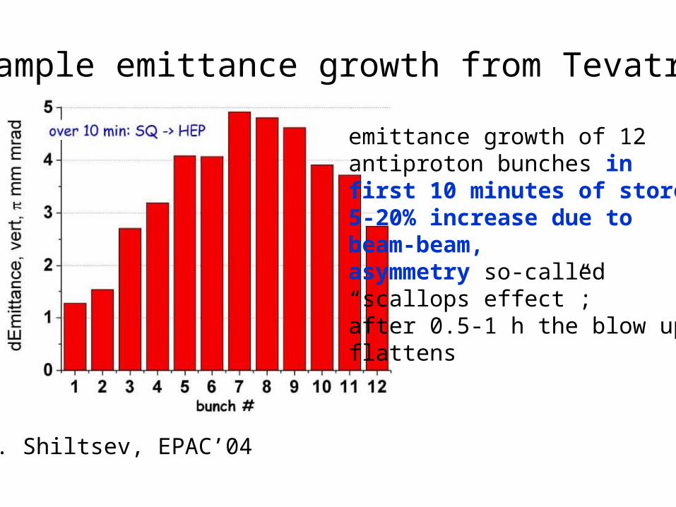
example emittance growth from Tevatron
emittance growth of 12 antiproton bunches infirst 10 minutes of store:5-20% increase due tobeam-beam, asymmetry so-called “scallops effect”;after 0.5-1 h the blow up flattens
V. Shiltsev, EPAC’04
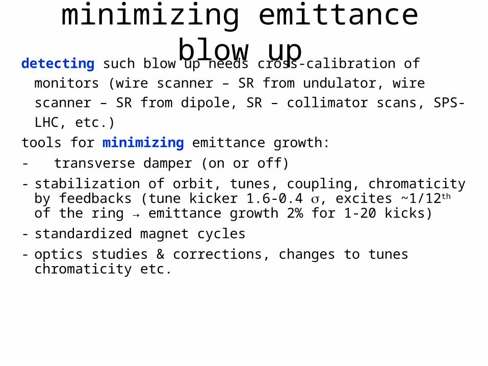
minimizing emittance blow updetecting such blow up needs cross-calibration of monitors (wire
scanner – SR from undulator, wire scanner – SR from dipole, SR – collimator scans, SPS-LHC, etc.)
tools for minimizing emittance growth: - transverse damper (on or off)- stabilization of orbit, tunes, coupling, chromaticity by
feedbacks (tune kicker 1.6-0.4 , excites ~1/12th of the ring → emittance growth 2% for 1-20 kicks)
- standardized magnet cycles- optics studies & corrections, changes to tunes chromaticity etc.
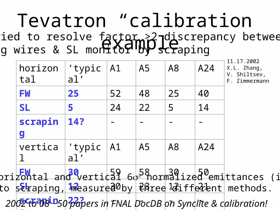
Tevatron “calibration” example
horizontal ‘typical’ A1 A5 A8 A24
FW 25 52 48 25 40
SL 5 24 22 5 14
scraping 14? - - - -
vertical ‘typical’ A1 A5 A8 A24
FW 30 59 58 30 50
SL 12 30 23 12 21
scraping 22? - - - -pbar horizontal and vertical 6 normalized emittances (in m) prior to scraping, measured by three different methods.
we tried to resolve factor >2 discrepancy between flying wires & SL monitor by scraping
11.17.2002X.L. Zhang,V. Shiltsev,F. Zimmermann
2002 to 08 ~50 papers in FNAL DocDB on Synclite & calibration!
longitudinal emittance
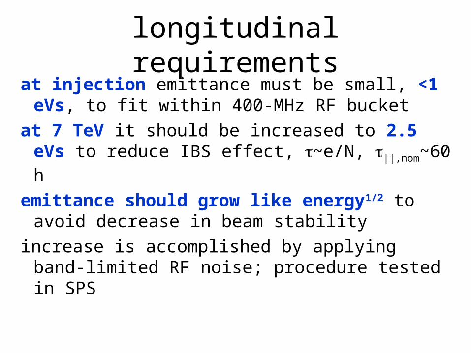
longitudinal requirementsat injection emittance must be small, <1 eVs, to
fit within 400-MHz RF bucketat 7 TeV it should be increased to 2.5 eVs to
reduce IBS effect, ~e/N, ||,nom~60 h
emittance should grow like energy1/2 to avoid decrease in beam stability
increase is accomplished by applying band-limited RF noise; procedure tested in SPS
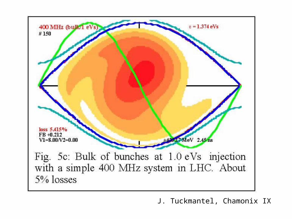
J. Tuckmantel, Chamonix IX
TOTEM
nominal25-ns, &75-ns
25-ns75-ns
TOTEMpilot
data from G. Arduini, LHC MAC 20, Dec. 2006
SPS emittance - dependence on #bunches & bunch intensity
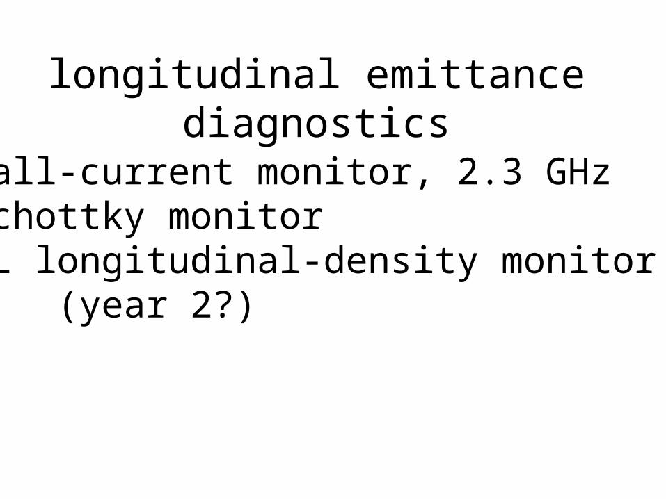
longitudinal emittance diagnostics
• wall-current monitor, 2.3 GHz• Schottky monitor • SL longitudinal-density monitor
(year 2?)
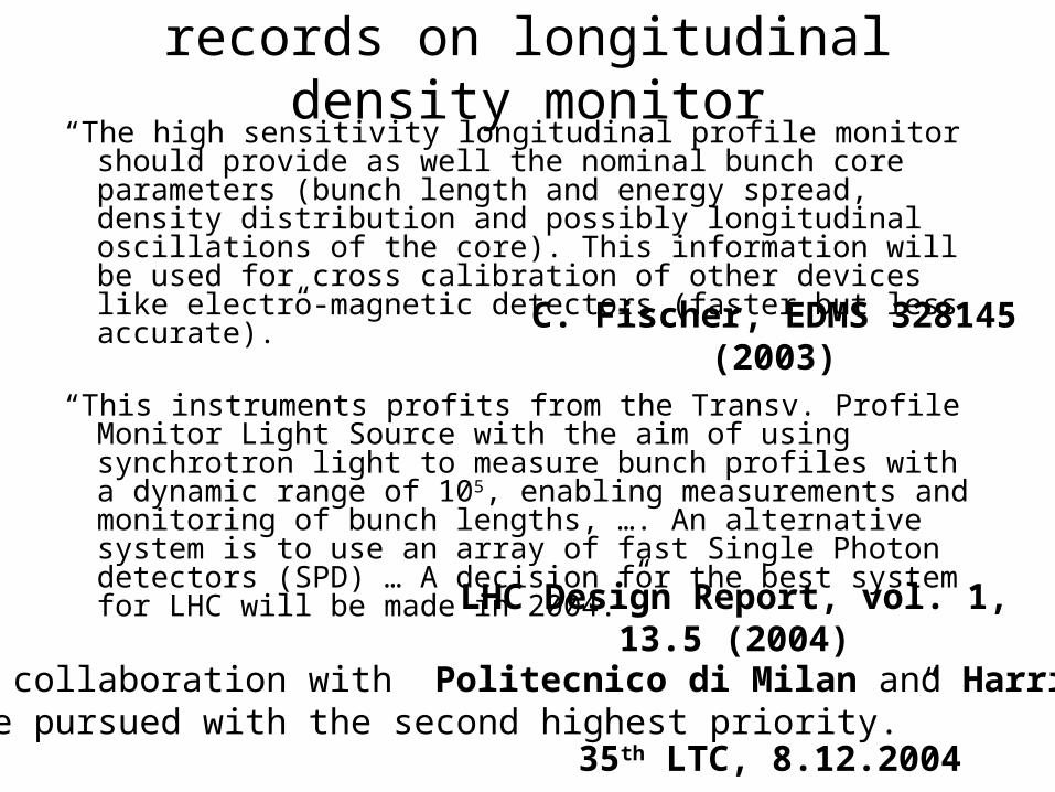
records on longitudinal density monitor“The high sensitivity longitudinal profile monitor should provide
as well the nominal bunch core parameters (bunch length and energy spread, density distribution and possibly longitudinal oscillations of the core). This information will be used for cross calibration of other devices like electro-magnetic detectors (faster but less accurate).”
“This instruments profits from the Transv. Profile Monitor Light Source with the aim of using synchrotron light to measure bunch profiles with a dynamic range of 105, enabling measurements and monitoring of bunch lengths, …. An alternative system is to use an array of fast Single Photon detectors (SPD) … A decision for the best system for LHC will be made in 2004.”
C. Fischer, EDMS 328145 (2003)
LHC Design Report, vol. 1, 13.5 (2004)
“The LDM collaboration with Politecnico di Milan and Harriot-Watt should be pursued with the second highest priority.”
35th LTC, 8.12.2004

A.Jansson, HHH-ABI Chamonix’07
momentum spread measurement with 1.7 GHz Schottky monitor at Tevatron; comparison with RW wide band pick up; at LHC 4.8 GHz Schottky pick-ups
Schottky monitor
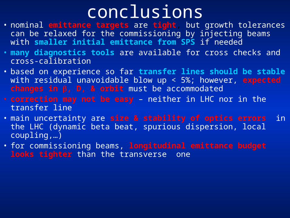
conclusions• nominal emittance targets are tight, but growth tolerances can be
relaxed for the commissioning by injecting beams with smaller initial emittance from SPS if needed
• many diagnostics tools are available for cross checks and cross-calibration
• based on experience so far transfer lines should be stable with residual unavoidable blow up < 5%; however, expected changes in , D, & orbit must be accommodated
• correction may not be easy – neither in LHC nor in the transfer line • main uncertainty are size & stability of optics errors in the LHC
(dynamic beta beat, spurious dispersion, local coupling,…)• for commissioning beams, longitudinal emittance budget looks tighter
than the transverse one
references
1) Y. Alexahin, “On the Emittance Growth due to Noise in Hadron Colliders and Methods of its Suppression,” NIM A, V. 391, 1, 73-76 (1997).
2) G. Arduini, “Mismatch Measurements,” Chamonix IX, 1999. 3) G. Arduini, “Status and Performance of the LHC (Proton) Injector Complex,” LHC MAC no. 20, December 20064) G. Arduini et al., “Analysis and Measurement of Coupling Effects in the Transfer Line from PS to SPS for the LHC Proton
Beam,” PAC 2001 Chicago. 5) E. Benedetto, “Optics Studies for the LHC Beam in the TT2-TT10 Line…”, APC 30.03.076) E. Benedetto, “Optics Changes for Protons and Ions in TT2/TT10,” APC 18.01.20087) A. Burns, “Beam Instrumentation,” Chamonix X, 2000.8) H. Burkhardt, “Overview of the LHC Injection and Transfer Line Optics Configurations and Tolerances,” Chamonix XIV 9) H. Burkhardt et al, “Collimation in the Transfer Lines to the LHC,” PAC 2005 Knoxville. 10) A. Guerrero Ollacarizqueta,S. Hutchins, “SPS Matching Tests,” APC 09.02.200711) A. Jansson, “Schottky Observations in the Tevatron,” CARE-HHH-ABI workshop Chamonix’0712) J. Uythoven, “TI2 Beam Test,” LTC 5 December 2007.13) C. Fischer, “Functional Specification – High Sensitivity Measurement of the Longitudinal Distribution of the LHC Beams,” LHC-
B-ES-0005.00 rev. 2.0 (2003).14) C. Fischer et al., “Functional Specification – Measurement of the Transverse Distribution in the LHC Rings,” LHC-B-ES-0006
rev. 1.0 (2003).15) B. Goddard et al., “Expected Emittance Growth and Beam Tail Repopulation from Errors at Injection into the LHC,” PAC2005
Knoxville (2005).16) B. Goddard et al., “Functional Specification – Interlocking of LHC BTV Screens,” LHC-BTV-ES-0001 rev. 1.0 (2007).17) K. Hanke, “Betatron Matching and Dispersion Matching,” Chamonix IX, 1999.18) A. Koschik et al, “Optics Flexibility and Dispersion Matching at Injection into the LHC,” EPAC 2006.19) O.R. Jones, “LHC Beam Instrumentation,” PAC07 Albuquerque 2007.20) F. Roncarolo, B. Dehning, “Transverse Emittance Blow-Up due to the Operation of Wire Scanners…,” CERN-AB-2005-042
(2005).21) E. Shaposhnikova, “Longitudinal Phenomena during the LHC Cycle,” Chamonix XI, 200122) E. Shaposhnikova, “Longitudinal Stability of the LHC Beam in the SPS,” CERN SL-Note-2001-035 HRF, 2001.23) V. Shiltsev, X.L.Zhang, F. Zimmermann, “Tevatron Study Report: Pbar Tunes & Pbar Removal 11/17/02, “CERN-AB-Note-
2003-007 (MD)24) V. Shiltsev, “Status of Tevatron Collider Run II and Novel Technologies for Luminosity Upgrades,” EPAC’04 Lucerne.25) J. Tuckmantel, “The SPS/LHC Longitudinal Interface,” Chamonix IX, 1999.26) J. Wenninger, “Functional Specification – Instrumentation for the Ti2 and Ti8 Transfer Lines,” LHC-B-ES-0004 rev.. 2.0 (2002).27) “Engineering Change Order – Class 1: Layout of the Beam Instrumentation in LSS4 Left and Right,” LHC-L3-EC-0009 ver. 1.0
(2005).28) LHC Design Report, Chapter 13