Electrical Tests and Root Cause Analysis of Insulation ...
54
Electrical Tests and Root Cause Analysis of Insulation System Faults Jan Petrik on behalf of WP11, contributions from: A. Foussat, L. Grand Clement, F. Evrard, J.B. Neyret, F.O. Pincot,J.C. Perez, S. Izquierdo Bermudez, F. Mangiarotti, G. Willering, G. Ninet, C. Scheuerlein, B.J Katzer, H. Prin, F. Savary, A. Milanese, F. Wolf Review of quench protection and electrical tests of 11 T dipole – 11/01/2019
Transcript of Electrical Tests and Root Cause Analysis of Insulation ...
Electrical Tests and Root Cause Analysis
of Insulation System Faults
Jan Petrik on behalf of WP11, contributions from:
A. Foussat, L. Grand Clement, F. Evrard, J.B. Neyret,
F.O. Pincot,J.C. Perez, S. Izquierdo Bermudez, F.
Mangiarotti, G. Willering, G. Ninet, C. Scheuerlein, B.J
Katzer, H. Prin, F. Savary, A. Milanese, F. Wolf
Review of quench protection and electrical tests of 11 T dipole – 11/01/2019
Presentation Outline
2Jan Petrik, 11/01/2019
Electrical tests overview
Hi-Pot measurements and test results
Fault investigation and extended Hi-Pot tests
Insulation system analysis
Ongoing tests
Summary
Presentation Outline
3Jan Petrik, 11/01/2019
Electrical tests overview
Hi-Pot measurements and test results
Fault investigation and extended Hi-Pot tests
Insulation system analysis
Ongoing tests
Summary
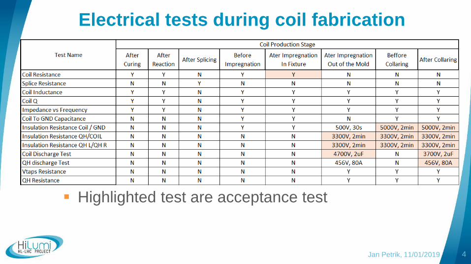
Electrical tests during coil fabrication
4Jan Petrik, 11/01/2019
Highlighted test are acceptance test
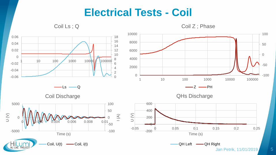
Electrical Tests - Coil
5
-100
-50
0
50
100
-5000
0
5000
0 0.002 0.004 0.006 0.008 0.01I (A
)
U (
V)
Time (s)
Coil Discharge
Coil, U(t) Coil, i(t)
-100
-50
0
50
100
0
2000
4000
6000
8000
10000
1 10 100 1000 10000 100000
Coil Z ; Phase
Z PH
0
2
4
6
8
10
12
14
16
18
-0.06
-0.04
-0.02
0
0.02
0.04
0.06
1 10 100 1000 10000 100000
Coil Ls ; Q
Ls Q
Jan Petrik, 11/01/2019
-200
0
200
400
600
-0.05 0 0.05 0.1 0.15 0.2 0.25U
(V
)Time (s)
QHs Discharge
QH Left QH Right
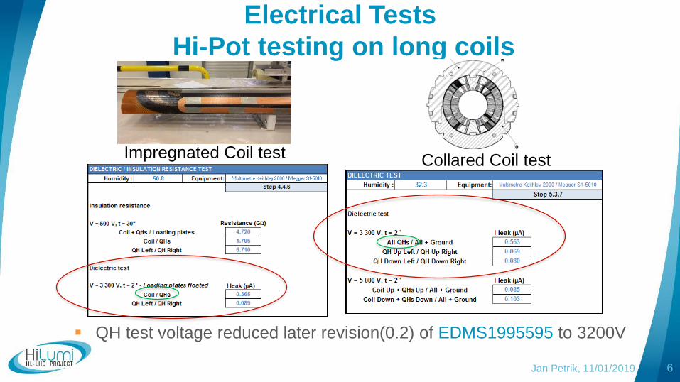
Electrical Tests
Hi-Pot testing on long coils
6
Impregnated Coil test Collared Coil test
QH test voltage reduced later revision(0.2) of EDMS1995595 to 3200V
Jan Petrik, 11/01/2019
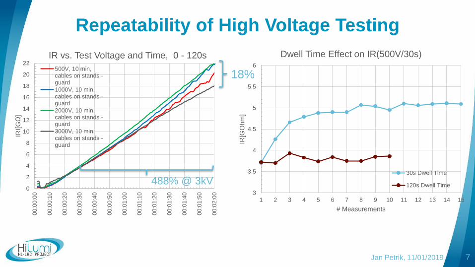
Repeatability of High Voltage Testing
7
0
2
4
6
8
10
12
14
16
18
20
22
00:0
0:0
0
00:0
0:1
0
00:0
0:2
0
00:0
0:3
0
00:0
0:4
0
00:0
0:5
0
00:0
1:0
0
00:0
1:1
0
00:0
1:2
0
00:0
1:3
0
00:0
1:4
0
00:0
1:5
0
00:0
2:0
0
IRI[G
Ω]
IR vs. Test Voltage and Time, 0 - 120s
500V, 10 min,cables on stands -guard
1000V, 10 min,cables on stands -guard
2000V, 10 min,cables on stands -guard
3000V, 10 min,cables on stands -guard
3
3.5
4
4.5
5
5.5
6
1 2 3 4 5 6 7 8 9 10 11 12 13 14 15
IR[G
Ohm
]
# Measurements
Dwell Time Effect on IR(500V/30s)
30s Dwell Time
120s Dwell Time
18%
488% @ 3kV
Jan Petrik, 11/01/2019

Observations on IR Testing
Jan Petrik, 11/01/2019
Test parameters (voltage, duration, ramps) are important!
They need to be stated with IR value
Different test conditions = IR values are not comparable
In case of successive tests, dwell time is important (min 4x*)
High value IR measurements are sensitive to
Surface leakage
Airflow, temperature, humidity…
More information in engineering report: EDMS2053320
* “A Stitch in time” A complete guide to electrical
insulation testing, Megger
Presentation Outline
9Jan Petrik, 11/01/2019
Electrical tests overview
Hi-Pot measurements and test results
Fault investigation and extended Hi-Pot tests
Insulation system analysis
Ongoing tests
Summary
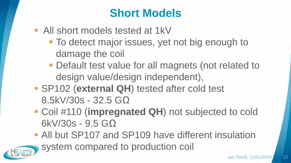
Short Models
10
All short models tested at 1kV
To detect major issues, yet not big enough to
damage the coil
Default test value for all magnets (not related to
design value/design independent),
SP102 (external QH) tested after cold test
8.5kV/30s - 32.5 GΩ
Coil #110 (impregnated QH) not subjected to cold
6kV/30s - 9.5 GΩ
All but SP107 and SP109 have different insulation
system compared to production coilJan Petrik, 11/01/2019
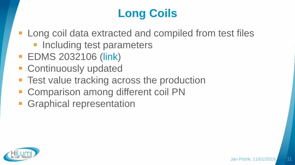
Long Coils
11
Long coil data extracted and compiled from test files
Including test parameters
EDMS 2032106 (link)
Continuously updated
Test value tracking across the production
Comparison among different coil PN
Graphical representation
Jan Petrik, 11/01/2019
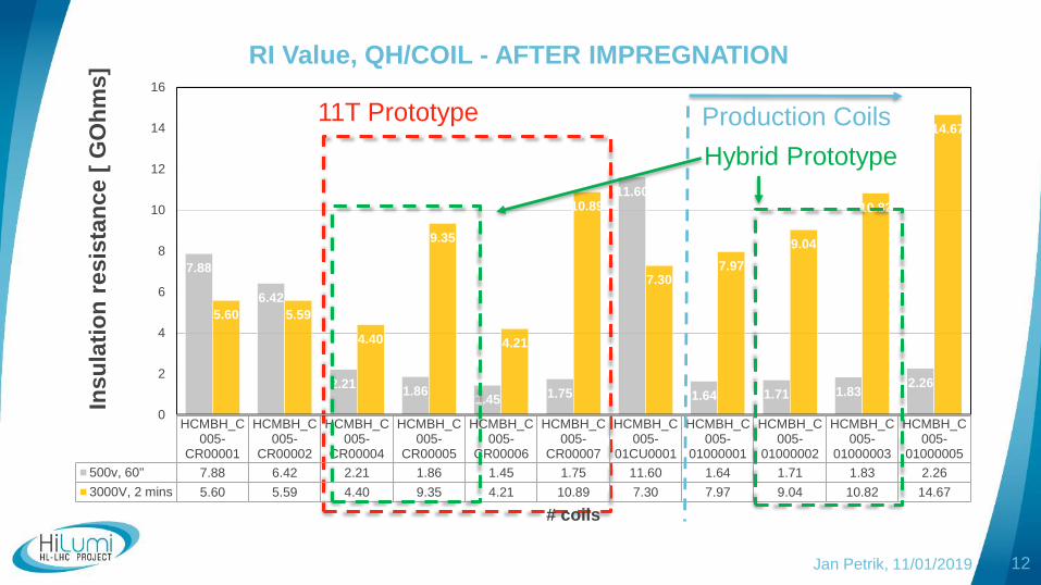
12
11T Prototype
HCMBH_C005-
CR00001
HCMBH_C005-
CR00002
HCMBH_C005-
CR00004
HCMBH_C005-
CR00005
HCMBH_C005-
CR00006
HCMBH_C005-
CR00007
HCMBH_C005-
01CU0001
HCMBH_C005-
01000001
HCMBH_C005-
01000002
HCMBH_C005-
01000003
HCMBH_C005-
01000005
500v, 60" 7.88 6.42 2.21 1.86 1.45 1.75 11.60 1.64 1.71 1.83 2.26
3000V, 2 mins 5.60 5.59 4.40 9.35 4.21 10.89 7.30 7.97 9.04 10.82 14.67
7.88
6.42
2.211.86
1.451.75
11.60
1.64 1.71 1.832.26
5.60 5.59
4.40
9.35
4.21
10.89
7.307.97
9.04
10.82
14.67
0
2
4
6
8
10
12
14
16In
su
lati
on
res
ista
nc
e [
GO
hm
s]
# coils
RI Value, QH/COIL - AFTER IMPREGNATION
Production Coils
Hybrid Prototype
Jan Petrik, 11/01/2019
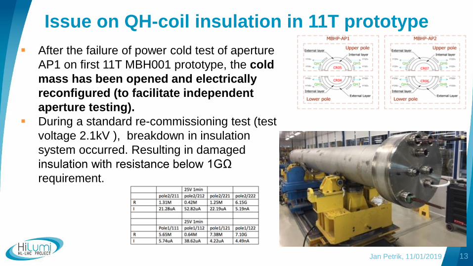
Issue on QH-coil insulation in 11T prototype
After the failure of power cold test of aperture
AP1 on first 11T MBH001 prototype, the cold
mass has been opened and electrically
reconfigured (to facilitate independent
aperture testing).
During a standard re-commissioning test (test
voltage 2.1kV ), breakdown in insulation
system occurred. Resulting in damaged
insulation with resistance below 1GΩ
requirement.
13Jan Petrik, 11/01/2019
Presentation Outline
14Jan Petrik, 11/01/2019
Electrical tests overview
Hi-Pot measurements and test results
Fault investigation and extended Hi-Pot tests
Insulation system analysis
Ongoing tests
Summary
Extended Test Program
in QH-Coil Insulation Goal of extended Hi-pot dielectric and discharge tests was to
burn-through insulation defect to facilitate fault
localization on prototype, and reproduce it on other 11T
coils and models
Successive use of MEGGER Burn mode (I leak < 3mA), C-
bank discharges using QPS (6 mF, 50-450V), CDG 7000(2
µF, 500-1000V).
All QH pushed to shorts, individually – either in collared or in
uncollared state.
15Jan Petrik, 11/01/2019
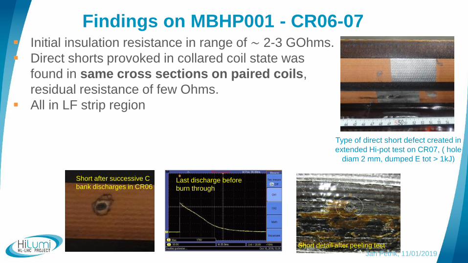
Findings on MBHP001 - CR06-07 Initial insulation resistance in range of ∼ 2-3 GOhms.
Direct shorts provoked in collared coil state was
found in same cross sections on paired coils,
residual resistance of few Ohms.
All in LF strip region
Type of direct short defect created in
extended Hi-pot test on CR07, ( hole
diam 2 mm, dumped E tot > 1kJ)
Short after successive C
bank discharges in CR06
16Short detail after peeling test
Last discharge before
burn through
Jan Petrik, 11/01/2019
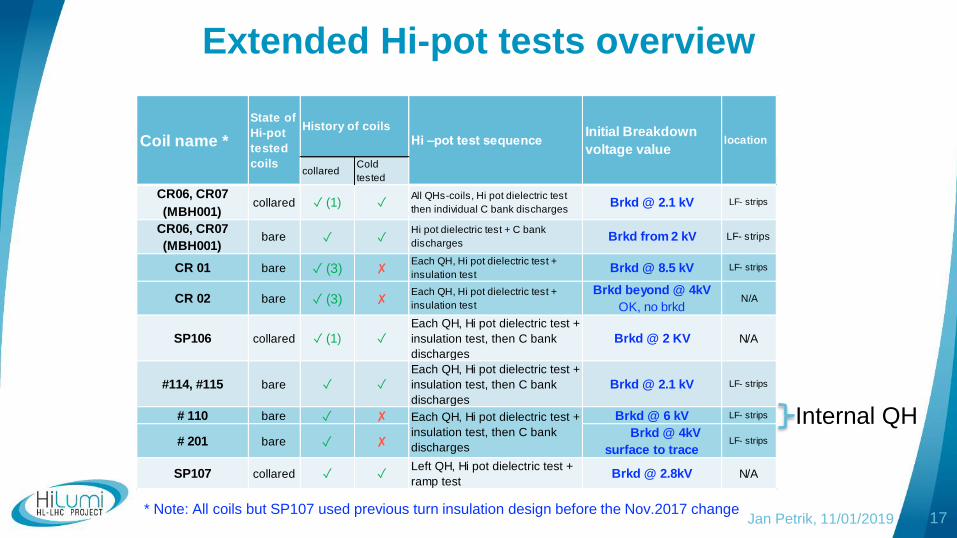
Extended Hi-pot tests overview
17* Note: All coils but SP107 used previous turn insulation design before the Nov.2017 change
collaredCold
tested
CR06, CR07
(MBH001)
CR06, CR07
(MBH001)
CR 01 bare (3) Each QH, Hi pot dielectric test +
insulation testBrkd @ 8.5 kV LF- strips
CR 02 bare (3) Each QH, Hi pot dielectric test +
insulation test
Brkd beyond @ 4kV
OK, no brkdN/A
SP106 collared (1)
Each QH, Hi pot dielectric test +
insulation test, then C bank
discharges
Brkd @ 2 KV N/A
#114, #115 bare
Each QH, Hi pot dielectric test +
insulation test, then C bank
discharges
Brkd @ 2.1 kV LF- strips
# 110 bare Brkd @ 6 kV LF- strips
# 201 bare Brkd @ 4kV
surface to traceLF- strips
SP107 collared Left QH, Hi pot dielectric test +
ramp testBrkd @ 2.8kV N/A
collared
bare
Each QH, Hi pot dielectric test +
insulation test, then C bank
discharges
(1) All QHs-coils, Hi pot dielectric test
then individual C bank dischargesBrkd @ 2.1 kV LF- strips
Hi pot dielectric test + C bank
dischargesBrkd from 2 kV LF- strips
locationCoil name *
State of
Hi-pot
tested
coils
History of coils
Hi –pot test sequenceInitial Breakdown
voltage value
Internal QH
Jan Petrik, 11/01/2019
Summary of Extended Hi-Pot tests
Both long and short cold tested bare coils show breakdown
voltage on QH-coil insulation of 2kV or larger.
Non cold-tested coils ( independently of collaring
history) show larger breakdown voltage value larger than
4kV (up to factor 4 @ 8.5kV)
Surface autopsy on prototype QHs did not reveal specific
defects, delamination, nor de-bonding
Defects in LF area
We were not able to reproduce damage pattern (to reduce
IR to MΩ in one Hi-Pot test) of 11Tprototype.
18Jan Petrik, 11/01/2019
Presentation Outline
19Jan Petrik, 11/01/2019
Electrical tests overview
Hi-Pot measurements and test results
Fault investigation and extended Hi-Pot tests
Insulation system analysis
Ongoing tests
Summary
Jan Petrik, 11/01/2019
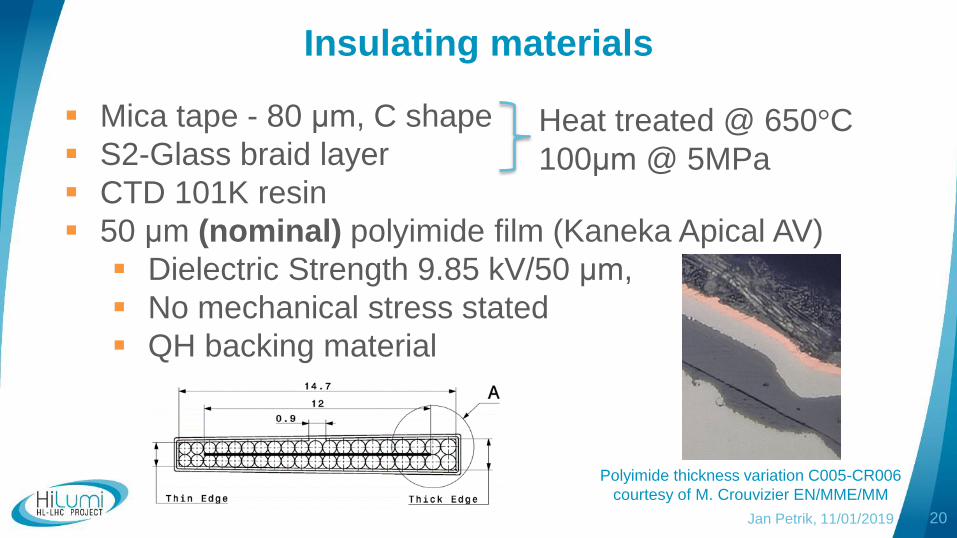
Insulating materials
Mica tape - 80 μm, C shape
S2-Glass braid layer
CTD 101K resin
50 μm (nominal) polyimide film (Kaneka Apical AV)
Dielectric Strength 9.85 kV/50 μm,
No mechanical stress stated
QH backing material
20
Heat treated @ 650°C
100μm @ 5MPa
Polyimide thickness variation C005-CR006
courtesy of M. Crouvizier EN/MME/MM
Jan Petrik, 11/01/2019
S2 Glass and Mica
Very brittle
Provides mechanical
spacing
Place for resin to go
21
Coil surface after 650°C heat treatment
SC cable with Mica and glass braid,
picture courtesy of S.I. Bermudez
Jan Petrik, 11/01/2019 22
Impregnated Coil
CTD 101K Insulation system
Datasheet value (link)
500um S2 Glass
No mechanical stress
11T average value of pressure is 50MPa
Thickness of resin not controlled
Integrity is not guaranteed (delamination, cracking)
Jan Petrik, 25/10/2018 23Jan Petrik, 11/01/2019
Jan Petrik, 11/01/2019 24
Recent Progress and Tests of Radiation Resistant
Impregnation Materials for Nb3Sn Coils
R. Bossert, S. Krave, G. Ambrosio, N. Andreev, G. Chlachidze, A.
Nobrega, I. Novitski, M. Yu and A.V. Zlobin
• 125 μm S2 Glass sleeve
• DOI: 10.1063/1.4860615, 2018
CTD 101K Insulation Under Pressure
Investigation of Alternative Materials for Impregnation
of Nb3Sn Magnets
Deepak R. Chichili, Jay Hoffman, and Alexander V. Zlobin
• 50% overlap of ceramic tape
• insulation thickness 0.250mm per cable
• DOI: 10.1109/TASC.2003.812892, 2003
Extrapolated/estimated breakdown voltage of 10 kV/1mm
Only resin and glass/ ceramic tape (no Polyimide)
Insulation System Imperfections
Jan Petrik, 11/01/2018 25
Coil #106 – cracks in resin
C005-010005 - Delamination along
edge of a new long coil.
Coil was not collared, neither cold
tested
Cross-section pictures of C005-CR006
courtesy of M. Crouvizier EN/MME/MM
C005-010003 – QH trace wrinkles,
probably linked to assembly
procedure (multiple mold opening –
not regular procedure)
Jan Petrik, 11/01/2018
Summary of Insulation Materials
Integrity of S2 Glass, Mica and CTD 101K resin
can’t be guaranteed during manufacturing and
commissioning
Although insulation system consist of multiple
layers, there is no redundancy
We rely on 50 μm (nominal value) of polyimide
Dielectric strength/integrity/thickness of the
other layers is not controlled/guaranteed
Our Hi-Pot test results are not in agreement with
polyimide datasheet values26
Presentation Outline
27Jan Petrik, 11/01/2019
Electrical tests overview
Hi-Pot measurements and test results
Fault investigation and extended Hi-Pot tests
Insulation system analysis
Ongoing tests
Summary
Pressure effects on polyimide dielectric
strength Extracted from QH
Sample size cca 3x4cm
Brkd. voltage test next
Jan Petrik, Felix Wolf, 11/01/2019 28
0
20
40
60
80
100
120
0
0.5
1
1.5
2
2.5
3
5 15 25 35 45 55 65 75 85 95 105 115 125 135
% r
ef.
to m
axim
um
IR[T
Ω]
Pressure [MPa]
IR vs Pressure3kV/30s
%
IR
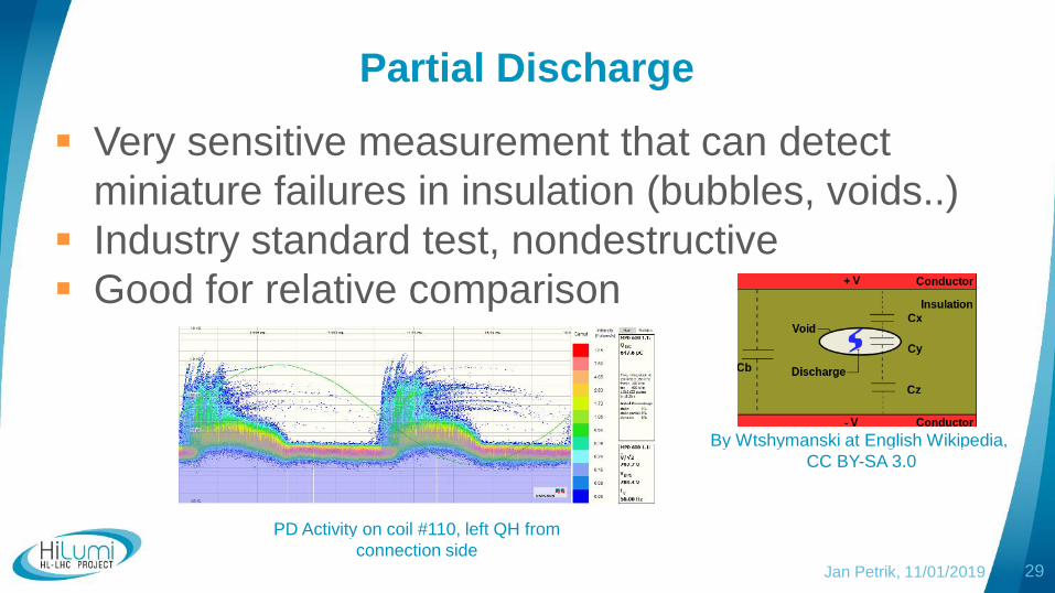
Partial Discharge
Very sensitive measurement that can detect
miniature failures in insulation (bubbles, voids..)
Industry standard test, nondestructive
Good for relative comparison
29
By Wtshymanski at English Wikipedia,
CC BY-SA 3.0
PD Activity on coil #110, left QH from
connection side
Jan Petrik, 11/01/2019
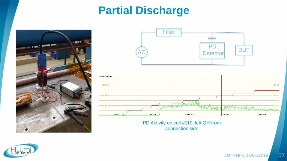
Jan Petrik, 11/01/2019 30
PD Activity on coil #110, left QH from
connection side
Partial Discharge
AC
Filter
PD
DetectorDUT
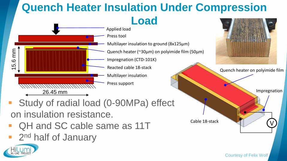
Quench Heater Insulation Under Compression
Load
Courtesy of Felix Wolf
Cable 18-stack
Quench heater on polyimide film
Impregnation
V
Applied load
Press tool
Quench heater (~30µm) on polyimide film (50µm)
Reacted cable 18-stack
Press support
Impregnation (CTD-101K)
Multilayer insulation to ground (8x125µm)
Multilayer insulation
15
.6 m
m
26.45 mm
Study of radial load (0-90MPa) effect
on insulation resistance.
QH and SC cable same as 11T
2nd half of January
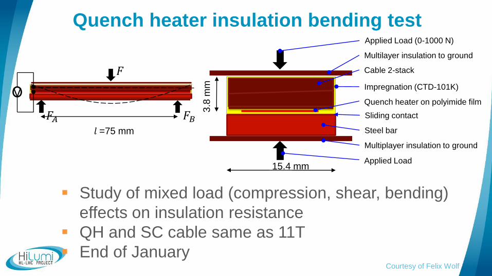
Quench heater insulation bending test
Courtesy of Felix Wolf
Study of mixed load (compression, shear, bending)
effects on insulation resistance
QH and SC cable same as 11T
End of January
𝑙 =75 mm
𝐹𝐴 𝐹𝐵
𝐹
VQuench heater on polyimide film
Cable 2-stack
Steel bar
3.8
mm
15.4 mm
Multilayer insulation to ground
Multiplayer insulation to ground
Applied Load
Sliding contact
Impregnation (CTD-101K)
Applied Load (0-1000 N)
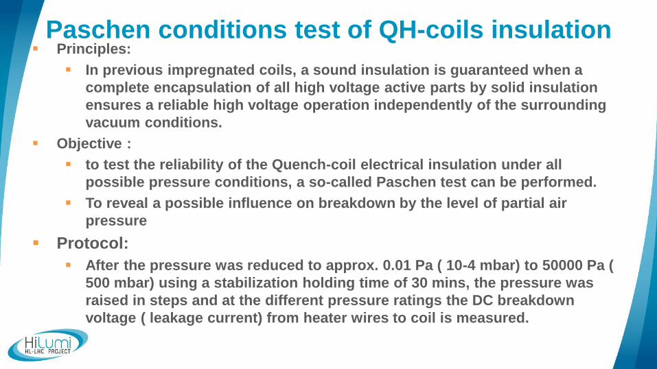
Paschen conditions test of QH-coils insulation Principles:
In previous impregnated coils, a sound insulation is guaranteed when a
complete encapsulation of all high voltage active parts by solid insulation
ensures a reliable high voltage operation independently of the surrounding
vacuum conditions.
Objective :
to test the reliability of the Quench-coil electrical insulation under all
possible pressure conditions, a so-called Paschen test can be performed.
To reveal a possible influence on breakdown by the level of partial air
pressure
Protocol:
After the pressure was reduced to approx. 0.01 Pa ( 10-4 mbar) to 50000 Pa (
500 mbar) using a stabilization holding time of 30 mins, the pressure was
raised in steps and at the different pressure ratings the DC breakdown
voltage ( leakage current) from heater wires to coil is measured.
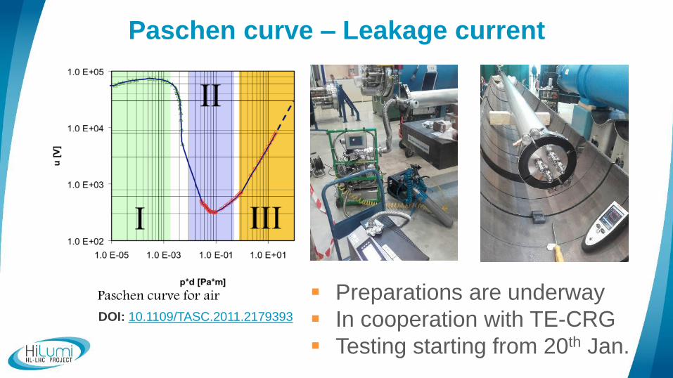
Paschen curve – Leakage current
DOI: 10.1109/TASC.2011.2179393
Paschen curve for air Preparations are underway
In cooperation with TE-CRG
Testing starting from 20th Jan.
Further planned tests
35
Effect of mechanical pressure on breakdown voltage of
polyimide (TE-MCS-LMF), 2nd half of January
Thermal cycling of collared pack at 77K + insulation
check (TE-MCS-LMF + TE-CRG-CI), early February
Extended QH testing SP109 – firing at increased
current (TE-MSC-TF), see Gerard’s talk
Paschen test in cryostat (TE-MSC-TF) – at 80K,100K,
200K
Jan Petrik, 11/01/2019
Presentation Outline
36Jan Petrik, 11/01/2019
Electrical tests overview
Hi-Pot measurements and test results
Fault investigation and extended Hi-Pot tests
Insulation system analysis
Ongoing tests
Summary
Summary
37
Insulation integrity is tested through the production at
various stages of coil production according to
specifications. QH to coil dielectric tested 3x times, plus
further testing is done during cold-mass assembly
11T prototype QH insulation damage has been
reproduced on both short and long coils
Weakness in LF area, under QH strip
Breakdown voltage is lower for cold tested coils
Jan Petrik, 11/01/2019
Summary
38
Integrity of resin and Mica tape can not be
guaranteed over the magnet lifetime
Multiple layers of insulation, yet no redundancy
There is no backup in case of Polyimide failure
More tests are underway to characterize the effect of
contact mechanical pressure, shear strain, partial gas
pressure and temperature on the insulation system
Jan Petrik, 11/01/2019
Back up Slides
39Jan Petrik, 11/01/2019
Improvement Suggestions
Possible improvements to our Hi-Pot tests:
Unify test parameters/introduce baseline measurement
for short models, long coils, cold testing
Collect more refined data - individual QH
Advanced measurements – Partial Discharge, PI
Improved Data management needs to be implemented in
order to facilitate online monitoring
More intensive testing of short models
Testing against design values, not acceptance criteria
40Jan Petrik, 11/01/2019
Links to overview tables
41
Short model table - link, sharepoint
Short model description tables – link, DFS
Long coil tables – link, EDMS
Jan Petrik, 11/01/2019
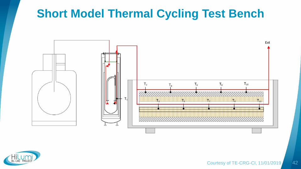
Short Model Thermal Cycling Test Bench
42Courtesy of TE-CRG-CI, 11/01/2019
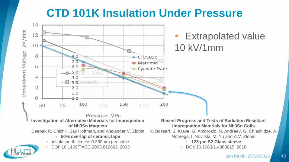
Jan Petrik, 25/10/2018 43
Recent Progress and Tests of Radiation Resistant
Impregnation Materials for Nb3Sn Coils
R. Bossert, S. Krave, G. Ambrosio, N. Andreev, G. Chlachidze, A.
Nobrega, I. Novitski, M. Yu and A.V. Zlobin
• 125 μm S2 Glass sleeve
• DOI: 10.1063/1.4860615, 2018
CTD 101K Insulation Under Pressure
Investigation of Alternative Materials for Impregnation
of Nb3Sn Magnets
Deepak R. Chichili, Jay Hoffman, and Alexander V. Zlobin
• 50% overlap of ceramic tape
• insulation thickness 0.250mm per cable
• DOI: 10.1109/TASC.2003.812892, 2003
Extrapolated value
10 kV/1mm
10 min. RI Test
Jan Petrik, 11/01/2019 44
0
10
20
30
40
50
60
70
80
90
100
110
120
130
140
150
160
00:0
0:0
0
00:0
0:3
0
00:0
1:0
0
00:0
1:3
0
00:0
2:0
0
00:0
2:3
0
00:0
3:0
0
00:0
3:3
0
00:0
4:0
0
00:0
4:3
0
00:0
5:0
0
00:0
5:3
0
00:0
6:0
0
00:0
6:3
0
00:0
7:0
0
00:0
7:3
0
00:0
8:0
0
00:0
8:3
0
00:0
9:0
0
00:0
9:3
0
00:1
0:0
0
RI[G
Ω]
RI vs. Test Voltage and Time500V, 10 min, cables on stands - guard
1000V, 10 min, cables on stands - guard
2000V, 10 min, cables on stands - guard
3000V, 10 min, cables on stands - guardGate Opened
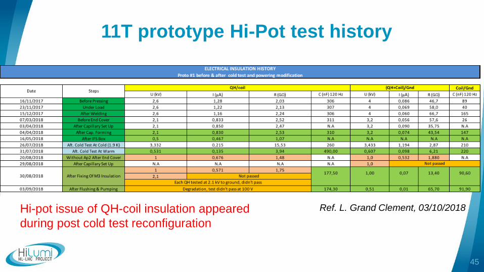
11T prototype Hi-Pot test history
45
Ref. L. Grand Clement, 03/10/2018Hi-pot issue of QH-coil insulation appeared
during post cold test reconfiguration
Short Model extended Test ProgramCourtesy of F-O Pincot TE-MSC-MDT
46
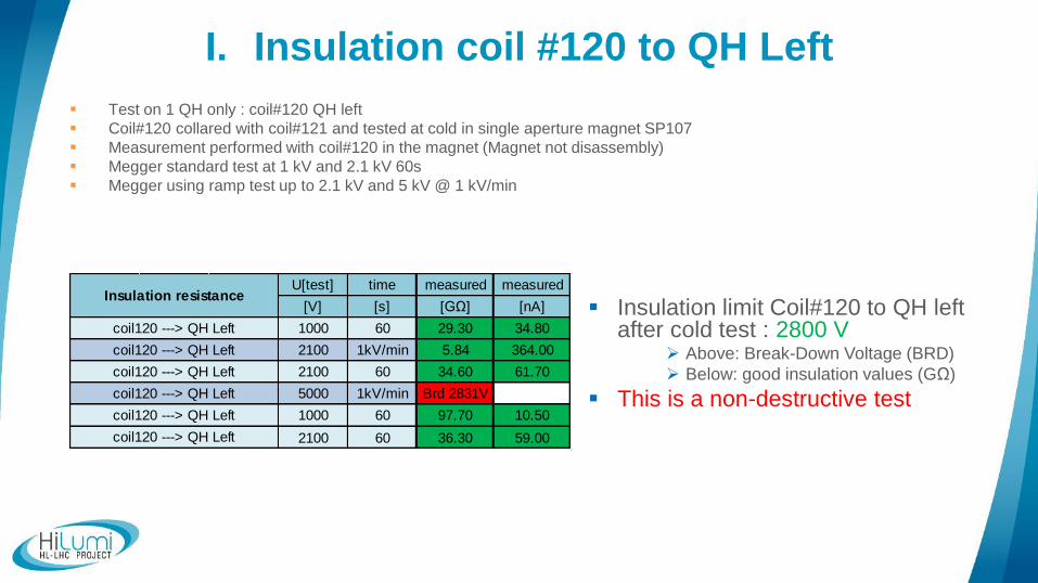
I. Insulation coil #120 to QH Left
Test on 1 QH only : coil#120 QH left
Coil#120 collared with coil#121 and tested at cold in single aperture magnet SP107
Measurement performed with coil#120 in the magnet (Magnet not disassembly)
Megger standard test at 1 kV and 2.1 kV 60s
Megger using ramp test up to 2.1 kV and 5 kV @ 1 kV/min
Insulation limit Coil#120 to QH left after cold test : 2800 V
Above: Break-Down Voltage (BRD)
Below: good insulation values (GΩ)
This is a non-destructive test
U[test] time measured measured
[V] [s] [GΩ] [nA]
1000 60 29.30 34.80
2100 1kV/min 5.84 364.00
2100 60 34.60 61.70
5000 1kV/min Brd 2831V
1000 60 97.70 10.50
2100 60 36.30 59.00
coil120 ---> QH Left
coil120 ---> QH Left
Insulation resistance
coil120 ---> QH Left
coil120 ---> QH Left
coil120 ---> QH Left
coil120 ---> QH Left
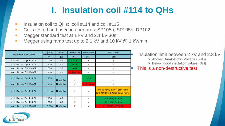
I. Insulation coil #114 to QHs
Insulation coil to QHs: coil #114 and coil #115
Coils tested and used in apertures: SP105a, SP105b, DP102
Megger standard test at 1 kV and 2.1 kV 30s
Megger using ramp test up to 2.1 kV and 10 kV @ 1 kV/min
Insulation limit between 2 kV and 2.3 kV: Above: Break-Down Voltage (BRD)
Below: good insulation values (GΩ)
This is a non-destructive test
U[test] time measured measured measured
[V] [s] [GΩ] [GΩ] [GΩ]
1000 30 10.5 X X
2100 30 9.77 X X
1000 30 9.63 X X
2100 30 Brd 2122V X X
21001kv/min X
3.38X
2100 1kv/min X Brd 1799V X
10 000 1kv/min X XBrd 2305V / 3.4GΩ (1st ramp)
Brd 2191V / 3.22GΩ (2nd ramp)
2100 60 X X 6.51GΩ / 329nA
1000 60 X X 12.15GΩ / 84nA
10 000 1kv/min X X Brd 1979V / 3.04GΩ
Insulation resistance
coil114 ---> QH 114 OL
coil114 ---> QH 114 OL
coil114 ---> QH 114 OR
coil114 ---> QH 114 OR
coil114 ---> QH 114 OL
coil114 ---> QH 114 OR
coil114 ---> QH 114 OR
coil114 ---> QH 114 OL
coil114 ---> QH 114 OL
coil114 ---> QH 114 OL
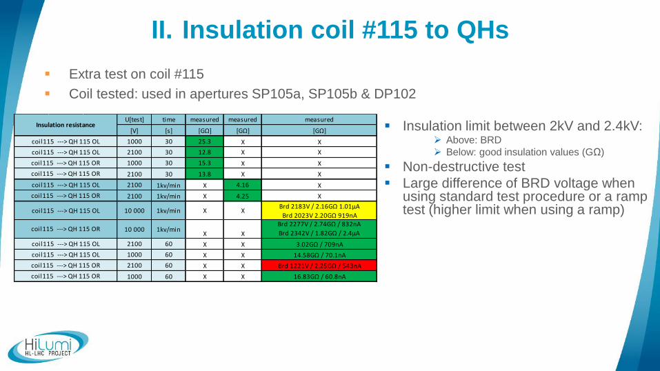
II. Insulation coil #115 to QHs
Extra test on coil #115
Coil tested: used in apertures SP105a, SP105b & DP102
Insulation limit between 2kV and 2.4kV: Above: BRD
Below: good insulation values (GΩ)
Non-destructive test
Large difference of BRD voltage when using standard test procedure or a ramp test (higher limit when using a ramp)
U[test] time measured measured measured
[V] [s] [GΩ] [GΩ] [GΩ]
1000 30 25.3 X X
2100 30 12.8 X X
1000 30 15.3 X X
2100 30 13.8 X X
2100 1kv/min X 4.16 X
2100 1kv/min X 4.25 X
10 000 1kv/min X XBrd 2183V / 2.16GΩ 1.01µA
Brd 2023V 2.20GΩ 919nA
10 000 1kv/minX X
Brd 2277V / 2.74GΩ / 832nA
Brd 2342V / 1.82GΩ / 2.4µA
2100 60 X X 3.02GΩ / 709nA
1000 60 X X 14.58GΩ / 70.1nA
2100 60 X X Brd 1221V / 2.25GΩ / 543nA
1000 60 X X 16.83GΩ / 60.8nA
coil115 ---> QH 115 OR
coil115 ---> QH 115 OL
coil115 ---> QH 115 OL
coil115 ---> QH 115 OR
coil115 ---> QH 115 OR
coil115 ---> QH 115 OL
coil115 ---> QH 115 OR
coil115 ---> QH 115 OL
coil115 ---> QH 115 OR
Insulation resistance
coil115 ---> QH 115 OL
coil115 ---> QH 115 OL
coil115 ---> QH 115 OR
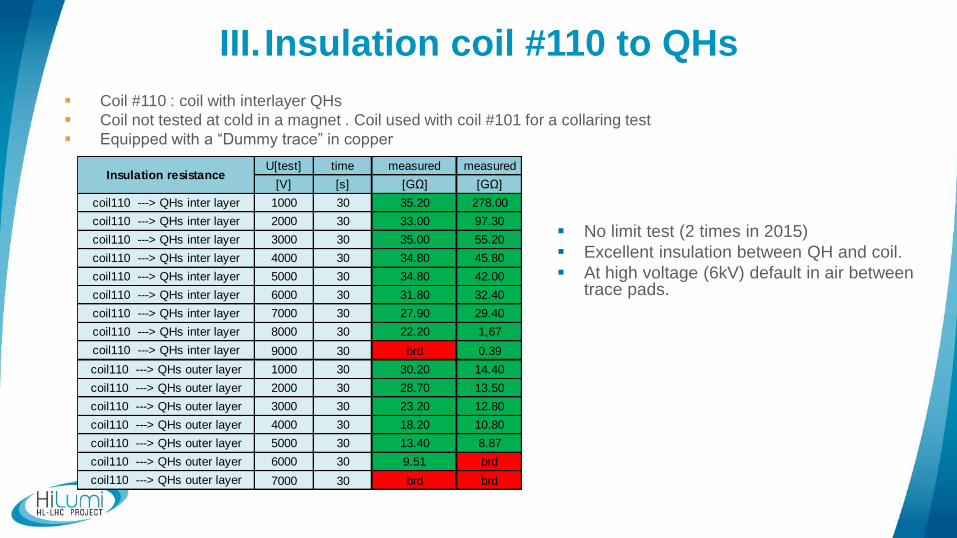
III. Insulation coil #110 to QHs
Coil #110 : coil with interlayer QHs
Coil not tested at cold in a magnet . Coil used with coil #101 for a collaring test
Equipped with a “Dummy trace” in copper
No limit test (2 times in 2015)
Excellent insulation between QH and coil.
At high voltage (6kV) default in air between trace pads.
U[test] time measured measured
[V] [s] [GΩ] [GΩ]
1000 30 35.20 278.00
2000 30 33.00 97.30
3000 30 35.00 55.20
4000 30 34.80 45.80
5000 30 34.80 42.00
6000 30 31.80 32.40
7000 30 27.90 29.40
8000 30 22.20 1,67
9000 30 brd 0.39
1000 30 30.20 14.40
2000 30 28.70 13.50
3000 30 23.20 12.80
4000 30 18.20 10.80
5000 30 13.40 8.87
6000 30 9.51 brd
7000 30 brd brd
coil110 ---> QHs outer layer
coil110 ---> QHs outer layer
coil110 ---> QHs outer layer
coil110 ---> QHs outer layer
coil110 ---> QHs outer layer
coil110 ---> QHs outer layer
coil110 ---> QHs outer layer
coil110 ---> QHs inter layer
coil110 ---> QHs inter layer
coil110 ---> QHs inter layer
coil110 ---> QHs inter layer
coil110 ---> QHs inter layer
Insulation resistance
coil110 ---> QHs inter layer
coil110 ---> QHs inter layer
coil110 ---> QHs inter layer
coil110 ---> QHs inter layer
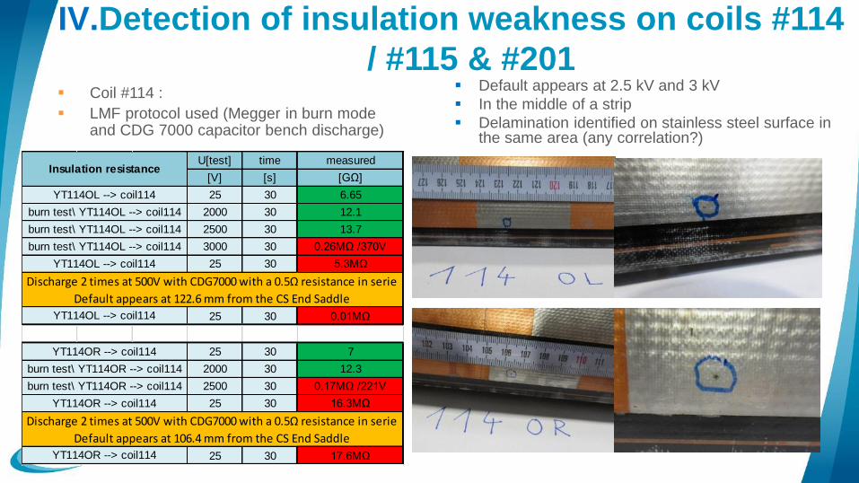
IV.Detection of insulation weakness on coils #114
/ #115 & #201 Coil #114 :
LMF protocol used (Megger in burn mode and CDG 7000 capacitor bench discharge)
Default appears at 2.5 kV and 3 kV
In the middle of a strip
Delamination identified on stainless steel surface in the same area (any correlation?)
U[test] time measured
[V] [s] [GΩ]
25 30 6.65
2000 30 12.1
2500 30 13.7
3000 30 0.26MΩ /370V
25 30 5.3MΩ
25 30 0.01MΩ
25 30 7
2000 30 12.3
2500 30 0.17MΩ /221V
25 30 16.3MΩ
25 30 17.6MΩYT114OR --> coil114
Insulation resistance
YT114OL --> coil114
burn test\ YT114OL --> coil114
burn test\ YT114OL --> coil114
burn test\ YT114OL --> coil114
YT114OR --> coil114
burn test\ YT114OR --> coil114
YT114OL --> coil114
YT114OR --> coil114
burn test\ YT114OR --> coil114
YT114OL --> coil114
Discharge 2 times at 500V with CDG7000 with a 0.5Ω resistance in serie
Default appears at 122.6 mm from the CS End Saddle
Discharge 2 times at 500V with CDG7000 with a 0.5Ω resistance in serie
Default appears at 106.4 mm from the CS End Saddle
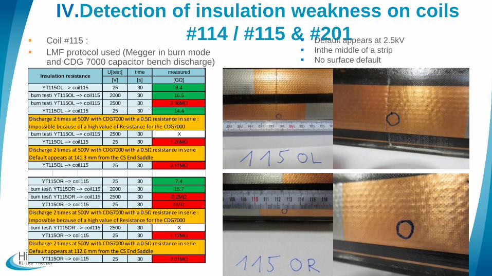
IV.Detection of insulation weakness on coils
#114 / #115 & #201 Coil #115 :
LMF protocol used (Megger in burn mode and CDG 7000 capacitor bench discharge)
Default appears at 2.5kV
Inthe middle of a strip
No surface default
U[test] time measured
[V] [s] [GΩ]
25 30 8.4
2000 30 16.6
2500 30 0.36MΩ
25 30 14.4
2500 30 X
25 30 1.26MΩ
25 30 0.11MΩ
25 30 7.4
2000 30 15.7
2500 30 0.2MΩ
25 30 5MΩ
2500 30 X
25 30 1.12MΩ
25 30 0.01MΩ
Discharge 2 times at 500V with CDG7000 with a 0.5Ω resistance in serie
Default appears at 141.3 mm from the CS End Saddle
Discharge 2 times at 500V with CDG7000 with a 0.5Ω resistance in serie :
Impossible because of a high value of Resistance for the CDG7000
Discharge 2 times at 500V with CDG7000 with a 0.5Ω resistance in serie
Default appears at 112.6 mm from the CS End Saddle
YT115OL --> coil115
burn test\ YT115OL --> coil115
YT115OL --> coil115
Insulation resistance
YT115OL --> coil115
burn test\ YT115OL --> coil115
burn test\ YT115OL --> coil115
Discharge 2 times at 500V with CDG7000 with a 0.5Ω resistance in serie :
Impossible because of a high value of Resistance for the CDG7000
YT115OR --> coil115
YT115OL --> coil115
YT115OR --> coil115
burn test\ YT115OR --> coil115
YT115OR --> coil115
YT115OR --> coil115
burn test\ YT115OR --> coil115
burn test\ YT115OR --> coil115
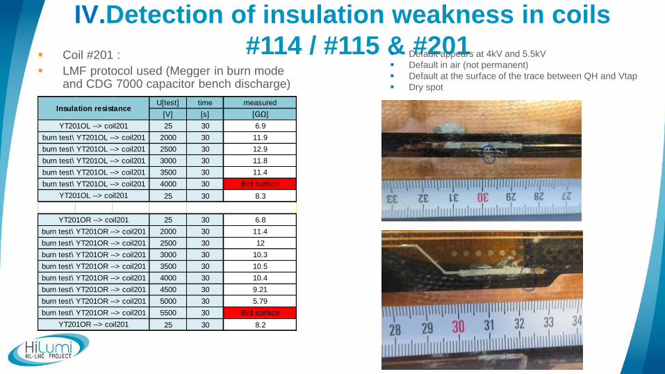
IV.Detection of insulation weakness in coils
#114 / #115 & #201 Coil #201 :
LMF protocol used (Megger in burn mode and CDG 7000 capacitor bench discharge)
Default appears at 4kV and 5.5kV
Default in air (not permanent)
Default at the surface of the trace between QH and Vtap
Dry spot
U[test] time measured
[V] [s] [GΩ]
25 30 6.9
2000 30 11.9
2500 30 12.9
3000 30 11.8
3500 30 11.4
4000 30 Brd surface
25 30 8.3
25 30 6.8
2000 30 11.4
2500 30 12
3000 30 10.3
3500 30 10.5
4000 30 10.4
4500 30 9.21
5000 30 5.79
5500 30 Brd surface
25 30 8.2
burn test\ YT201OL --> coil201
burn test\ YT201OR --> coil201
burn test\ YT201OR --> coil201
burn test\ YT201OR --> coil201
Insulation resistance
YT201OL --> coil201
burn test\ YT201OL --> coil201
burn test\ YT201OR --> coil201
burn test\ YT201OL --> coil201
YT201OL --> coil201
burn test\ YT201OL --> coil201
burn test\ YT201OL --> coil201
YT201OR --> coil201
YT201OR --> coil201
burn test\ YT201OR --> coil201
burn test\ YT201OR --> coil201
burn test\ YT201OR --> coil201
burn test\ YT201OR --> coil201
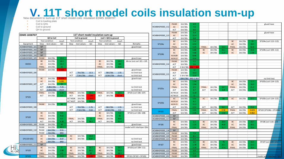
V. 11T short model coils insulation sum-up New document to sum-up 11T short model coils insulation EDMS 1838707:
Coil to loading plate
Coil to QHs
Coil to ground
QH to ground
EDMS 1838707
result result result
Equipment Step test values GΩ Step test values GΩ Step test values GΩ Remarks
HCMBHSP0003_101 NP glued trace
HCMBHSP0003_102 NP
HCMBHSP0003_103 NP
HCMBHSP0003_104 NP
HCMBHSP0003_105 PAIWI 1kV/30s 13.4 glued trace
BC 1kV/30s 16.5 BC 1kV/30s 14.2 Mirror test coil 101 + 105
AC 1kV/30s 12.2 AC 1kV/30s 180
FINAL 1kV/30s 15 FINAL 1kV/30s 35.8
PAIWI 1kV/30s 0.024 glued trace
ACT 7kV/30s 13.3 ACT 8kV/30s 1.55 no limit test
ACT 7.5kV/30s short ACT 8.5kV/30s short no limit test
BC 1kV/30s 0.074 glued trace
AC 1kV/30s 0.095
ACT 1kV/30s 29
ACT 5.8kV/30s 7.25 no limit test
ACT 6.5kV/30s short no limit test
FINAL 1kV/30s 3.24 FINAL 1kV/30s 29.5 FINAL 1kV/30s 22.5 SP101 (coil 106+ 107)
ACT 1kV/30s 3.5 ACT 1kV/30s 0.044 ACT 1kV/30s 0.028
ACT #106 1kV/30s 0.071
ACT #107 1kV/30s 34.4
PAIWI 1kV/30s 40 glued trace
ACT 7kV/30s 1.76 ACT 8kV/30s 1.55 no limit test
ACT 7.5kV/30s 0.64 ACT 8.5kV/30s 0.6 no limit test
BC 1kV/30s 9.4 BC 1kV/30s 5.2 SP102 (coil 106+ 108)
AC 1kV/30s 4.62 AC 1kV/30s 35
FINAL 1kV/30s 4.3 FINAL 1kV/30s 32 FINAL 1kV/30s 36.6
ACT 1kV/30s 4.38 ACT 1kV/30s 58.5 ACT 1kV/30s 31.4
HCMBHSP0003_109 PAIWI 1kV/30s 40 glued trace
PAIWI 1kV/30s 30.2 model with interlayer QHs
PAIWI 6kV/30s 9.51
PAIWI 7kV/30s BRD
AC 1kV/30s 14.4 AC 1kV/30s 14.4
AC 5kV/30s 8.87 AC 2kV/30s 8.87 no limit test
AC 6kV/30s BRD no limit test
HCMBHSP0003_111 NP glued trace
BC 1kV/30s 9 BC 1kV/30s 36.7 BC 1kV/30s 29.7 SP103 (coil 109+ 111)
AC 1kV/30s 3.88 AC 1kV/30s 30.1 AC 1kV/30s 33.3
FINAL 1kV/30s 4.5 FINAL 1kV/30s 82 FINAL 1kV/30s 68.3
DP101 FINAL 1kV/30s 2.03 FINAL 1kV/30s 0.069 FINAL 1kV/30s 0.06 DP101 (SP102 + SP103)
SP103
HCMBHSP0003_108
SP102
HCMBHSP0003_110
SP(110+101)
11T short model insulation sum-up
SM101
HCMBHSP0003_106
HCMBHSP0003_107
SP101
Test condition
QH to Coil Coil to ground
Test condition
(coil + QH) to ground
Test condition
PAIWI 1kV/30s 4.9 glued trace
AC 1kV/30s 7.6
ACT 1kV/30s 6.6
PAIWI 1kV/30s 5.4 glued trace
AC 1kV/30s 11.4
ACT 1kV/30s 8.8
BC 1kV/30s 7.4 BC 1kV/30s 19 SP104a (coil 112+ 113)
AC 1kV/30s 4.52 AC 1kV/30s 28.5
FINAL 1kV/30s 5.25 FINAL 1kV/30s 24.3 FINAL 1kV/30s 62.8
BC 1kV/30s 6.86 BC 1kV/30s 55.1 BC 1kV/30s 44.8 SP104b (coil 109+ 112)
AC 1kV/30s 4.66 AC 1kV/30s 3.27 AC 1kV/30s 2.59
AC#109 1kV/30s 8.46
AC#112 1kV/30s 15.6
PAIWI 1kV/30s 5.5
ACT 1kV/30s 9.6
ACT 2.1kV/30s BRD 1.9kV
PAIWI 1kV/30s 13
ACT 1kV/30s 15.3
ACT 2.1kV/30s 12.8
ACT 10kV/30s BRD 2.2kV no limit test
BC 1kV/30s 1.54 BC 1kV/30s 11.3 SP105a (coil 114+ 115)
AC 1kV/30s 2.94 AC 1kV/30s 16.9
FINAL 1kV/30s 2.5 FINAL 1kV/30s 19.7 FINAL 1kV/30s 21.2
ACT 1kV/30s 3.7 ACT 1kV/30s 6.8 ACT 1kV/30s 6.75
ACT#114 1kV/30s 11.8
ACT#115 1kV/30s 11
AC 1kV/30s 3.91 AC 1kV/30s 84 AC 1kV/30s 37.7 SP105b (coil 114+ 115)
AC#114 1kV/30s 8.2
AC#115 1kV/30s 11.2
ACT 1kV/30s 4.51 ACT 1kV/30s 34.1 ACT 1kV/30s 25.6
FINAL 1kV/30s 2.01 FINAL 1kV/30s 0.58 FINAL 1kV/30s 0.623 DP102 (SP104b + SP105b)
ACT 1kV/30s 2.35 ACT 1kV/30s 1.42 ACT 1kV/30s 0.862
HCMBHSP0003_116 NP
HCMBHSP0003_117 NP
BC 1kV/30s 2.2 BC 1kV/30s 28.9 BC 1kV/30s 20.7 SP106 (coil 116+ 117)
AC 1kV/30s 2.25 AC 1kV/30s 46.8 AC 1kV/30s 30.1
FINAL 1kV/30s 2.51 FINAL 1kV/30s 31.7 FINAL 1kV/30s 33.4
HCMBHSP0003_118 NP
HCMBHSP0003_119 PAIWI 1kV/30s 7.9
HCMBHSP0003_120 PAIWI 1kV/30s 8.1
HCMBHSP0003_121 PAIWI 1kV/30s 7.7
BC 1kV/30s 2.6 BC 1kV/30s 75 BC 1kV/30s 34.5 SP107 (coil 120+ 121)
AC 1kV/30s 2.78 AC 1kV/30s 26.1 AC 1kV/30s 23.3
FINAL 1kV/30s 3.19 FINAL 1kV/30s 37.4 FINAL 1kV/30s 28.4
HCMBHSP0003_122 PAIWI 1kV/30s 6.8
HCMBHSP0003_123 PAIWI 1kV/30s 5.5
HCMBHSP0003_201 PAIWI 1kV/30s 5.29 model with interlayer QHs
SP105b
SP106
SP107
DP102
HCMBHSP0003_113
SP104a
SP104b
HCMBHSP0003_114
HCMBHSP0003_115
SP105a
HCMBHSP0003_112