EIM2, EIM2.120, EIM2 - download.vimar.com · HIDDY 350A può azionare agevolmente cancelli e...
16
Manuale per il collegamento e l’uso Installation and operation manual EIM2, EIM2.120, EIM2.180 Attuatore interrato 120/230 V 3,5 m Underground actuator 120/230 V 3,5 m
Transcript of EIM2, EIM2.120, EIM2 - download.vimar.com · HIDDY 350A può azionare agevolmente cancelli e...
Manuale per il collegamento e l’uso Installation and operation manual
EIM2, EIM2.120, EIM2.180Attuatore interrato 120/230 V 3,5 m
Underground actuator 120/230 V 3,5 m

2
HIDDY 350A
IT
2 - Layout impianto EIM2 (110°)
1 - Caratteristiche tecnicheHIDDY 350A è un operatore irreversibile con finecorsa meccanici e coperchio carrabile.HIDDY 350A è dotato di variazione di velocità dell’anta sia in apertura che in chiusura (apertura iniziale lenta, poi veloce e chiusura inizialmente veloce, poi lenta all’arrivo in battuta).HIDDY 350A è portante dell’anta del cancello e in caso di manutenzione il motore può essere rimosso senza togliere l’anta.HIDDY 350A può azionare agevolmente cancelli e portoni pesanti fino a 800 kg con ante lunghe fino a 2 m.
CARATTERISTICHE TECNICHE
HIDDY 350A110°
HIDDY 350A180°
Lunghezza max. anta (m.) 3,5*Peso max cancello (Kg) 800 (2 m) - 400 (3,5 m)Tempo medio di apertura (s.) 20 30Coppia max (Nm) 330Alimentazione e frequenza 230 V~ 50/60 HzPotenza motore (W) 302Assorbimento (A) 1,5Condensatore (µF) 10Alimentazione e frequenza 120 V~ 60 HzPotenza motore (W) 319Assorbimento (A) 3,7Condensatore (µF) 35Lubrificazione a grassoPeso operatore + cassa (kg) 21Rumorosità (db) <70Temperatura di lavoro (°C) -10 ÷ +55 °CGrado di protezione (IP) 67
* E’ consigliabile prevedere una serratura elettrica per ante superiori a 2 m.
A B
C
LG
I
F
E
A B
G
L
H
D2x0,5mm2
4x1,5 mm2
2x0,5mm2 4x0,5mm2
3x0,5mm2
2x1mm2
3x1,5mm2
230/120 Vac
C
A - Attuatore interrato (EIM2) F - Radiocomando 2 canaliB - Cassa di fondazione (EIC5) G - Coppia di fotocelluleC - Sblocco (EIS5.L) H - SelettoreD - Centralina di comando (ECA8) I - ElettroserraturaE - Lampeggiante (ELA6) L - Scatola di derivazione 1A

1
HIDDY 350A
IT
114
Ø 35Ø 35
Ø 80 Ø 80
385327
240163
163
629527 6767 27
66
80
114
Layout impianto EIM2.180 (180°)
Misure in mm
A B
C
MH
L
G
F
A B
H
M
I
E2x0,5mm2
4x1,5 mm2
2x0,5mm2 4x0,5mm2
3x0,5mm2
2x1mm2
3x1,5mm2
230/120 Vac
C
A - Attuatore interrato (EIM2.180) F - Lampeggiante (ELA6)B - Cassa di fondazione (EIC5) G - Radiocomando 2 canaliC - Sblocco (EIS5.L) H - Coppia di fotocelluleD - Accessori conversione cassa 180° (EIX1.180)
I - SelettoreL - Elettroserratura
E - Centralina di comando (ECA8) M - Scatola di derivazione
D D
1B
2
2
HIDDY 350A
IT
250
460 380
3 - Installazione
3.1 - Controllo pre-installazioneLe ante devono essere solidamente fissate ai cardini delle colonne, nondevono flettere durante il movimento e devono muoversi senza attriti.Prima d’installare HIDDY 350A è meglio verificare tutti gli ingombri necessari per poterlo installare.Se il cancello si presenta come da Fig. 1 non occorrono modifiche.È obbligatorio uniformare le caratteristiche del cancello alle normee leggi vigenti. Il cancello può essere automatizzato solo se in buono stato e se rispondente alla norma EN 12604.- L’anta non deve presentare porte pedonali. In caso contrario
occorrerà prendere opportune precauzioni in accordo al punto 5.4.1 della EN12453 (ad esempio impedire il movimento del motore quando il portoncino è aperto, grazie ad un microinterruttore opportunamente collegato al quadro elettronico).
- Non bisogna generare punti di intrappolamento (ad esempio tra anta aperta del cancello e cancellata).
- Non devono essere presenti fermi meccanici al di sopra del cancello perché non sono sufficientemente sicuri.
3.2 - Preparazione cementazione cassa- Eseguire una buca nel terreno vicino al pilastro (Fig. 3).- Predisporre sul fondo della cassa di fondazione un tubo Ø 50 mm in
PVC per lo scarico dell’acqua e su un lato un tubo Ø 32 mm di tipo isolante flessibile pesante per l’uscita dei cavi elettrici (utilizzare i fori del lato interno dell’apertura cancello).
LA GIUNZIONE DEI CAVI DEVE AVVENIRE all’interno di una scatola di derivazione stagna posta ALL’ESTERNO DELLA CASSA DI FONDAZIONE, murata o fissata ad un’altezza minima di sicurezza e dovrà garantire il rispetto delle norme.- Con una livella posizionate la cassa di fondazione in modo che il filo
superiore del coperchio corrisponda al piano finito del pavimento.- L’asse del perno della cassa deve corrispondere perfettamente
all’asse del cardine.- Per HIDDY 350A 110° (EIM2): cementate la cassa di fondazione
verificando che i suoi lati più corti siano perfettamente paralleli al cancello quando è CHIUSO.
- Per HIDDY 350A 180° (EIM2.180): cementate la cassa di fondazione verificando che i suoi lati più corti siano perfettamente perpendicolari al cancello quando è CHIUSO.
- Inserire i dadi a gabbietta per il fissaggio del coperchio nelle apposite sedi ricavate nella cassa di fondazione.
Tubo per cavi elettrici
Tubo per scarico acqua
Tubo per scarico acqua
Tubo per cavi elettrici
3
4
5
3
HIDDY 350A
IT
SX DX
FE E
DXSX
2 2A A
B 1 B 1
C
B
A
F
D
DXSX
2 2A A
B 1 B 1
C
B
A
F
D
CANCELLO CHIUSO CANCELLO CHIUSO
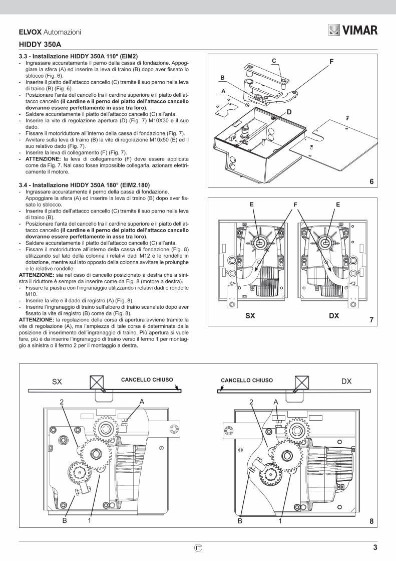
3.3 - Installazione HIDDY 350A 110° (EIM2)- Ingrassare accuratamente il perno della cassa di fondazione. Appog-
giare la sfera (A) ed inserire la leva di traino (B) dopo aver fissato lo sblocco (Fig. 6).
- Inserire il piatto dell’attacco cancello (C) tramite il suo perno nella leva di traino (B) (Fig. 6).
- Posizionare l’anta del cancello tra il cardine superiore e il piatto dell’at-tacco cancello (il cardine e il perno del piatto dell’attacco cancello dovranno essere perfettamente in asse tra loro).
- Saldare accuratamente il piatto dell’attacco cancello (C) all’anta.- Inserire la vite di regolazione apertura (D) (Fig. 7) M10X30 e il suo
dado.- Fissare il motoriduttore all’interno della cassa di fondazione (Fig. 7).- Avvitare sulla leva di traino (B) la vite di regolazione M10x50 (E) ed il
suo relativo dado (Fig. 7).- Inserire la leva di collegamento (F) (Fig. 7).- ATTENZIONE: la leva di collegamento (F) deve essere applicata
come da Fig. 7. Nal caso fosse impossible collegarla, azionare elettri-camente il motore.
3.4 - Installazione HIDDY 350A 180° (EIM2.180)- Ingrassare accuratamente il perno della cassa di fondazione. Appoggiare la sfera (A) ed inserire la leva di traino (B) dopo aver fis-
sato lo sblocco.- Inserire il piatto dell’attacco cancello (C) tramite il suo perno nella leva
di traino (B).- Posizionare l’anta del cancello tra il cardine superiore e il piatto dell’at-
tacco cancello (il cardine e il perno del piatto dell’attacco cancello dovranno essere perfettamente in asse tra loro).
- Saldare accuratamente il piatto dell’attacco cancello (C) all’anta. - Fissare il motoriduttore all’interno della cassa di fondazione (Fig. 8)
utilizzando sul lato della colonna i relativi dadi M12 e le rondelle in dotazione, mentre sul lato opposto della colonna avvitare le prolunghe e le relative rondelle.
ATTENZIONE: sia nel caso di cancello posizionato a destra che a sini-stra il riduttore è sempre da inserire come da Fig. 8 (motore a destra).- Fissare la piastra con l’ingranaggio utilizzando i relativi dadi e rondelle
M10.- Inserire la vite e il dado di registro (A) (Fig. 8).- Inserire l’ingranaggio di traino sull’albero di traino scanalato dopo aver
fissato la vite di registro (B) come da (Fig. 8).ATTENZIONE: la regolazione della corsa di apertura avviene tramite la vite di regolazione (A), ma l’ampiezza di tale corsa è determinata dalla posizione di inserimento dell’ingranaggio di traino. Più apertura si vuole fare, più è da inserire l’ingranaggio di traino verso il fermo 1 per montag-gio a sinistra o il fermo 2 per il montaggio a destra.
6
7
8

4
HIDDY 350A
IT
C C
B
EIS5.L
3.5 - Regolazione arresti meccanici HIDDY 350A 110° (EIM2)Usando il HIDDY 350A non è necessario fissare fermi a terra o altro perché è dotato all’interno di viti di fermo registrabili per delimitare la corsa dell’anta.Per accedere alle viti è necessario togliere il coperchio del HIDDY 350A.- Per ottenere l’apertura desiderata del cancello è sufficiente avvitare o
svitare l’apposita vite (D) di fermo e di seguito bloccare il controdado per impedire che possa modificare la sua posizione nel tempo (Fig. 6).
La stessa regolazione va eseguita anche sulla vite (E) per la chiusura facendo in modo di permettere nell’operazione di sblocco il riaggancio del meccanismo (Fig. 7).
ATTENZIONE: in chiusura impedite che le ante sbattano sul fermo a terra. L’anta deve fermarsi per l’intervento del finecorsa meccanico interno. In caso contrario risulta impossibile lo sbloccaggio.
3.6 - Collegamento elettricoDa effettuare dopo aver tolto l’alimentazione elettrica al motore alla centrale di comando. Fare riferimento alla indicazioni di Fig. 11.
3.7 - Sblocco di emergenzaDa effettuare dopo aver tolto l’alimentazione elettrica al motore.Per poter eseguire in modo sicuro la movimentazione manuale dell’anta occorre verificare che:- lo sforzo manuale per muovere l’anta non superi rientri nei limiti
previsti dalla norma EN12453 In caso di mancanza di energia elettrica, per poter aprire manualmente
il cancello è sufficente agire sullo sblocco posto sulla leva di traino.
ATTENZIONE: in chiusura impedire che le ante sbattano sul fermo. L’anta deve fermarsi per l’intervento del finecorsa meccanico interno. In caso contrario risulta impossibile lo sbloccaggio.
3.8 - Regolazione frizioneIn HIDDY 350A il limitatore di coppia meccanico non è presente. É quindi necessario comandare questo operatore con un quadro elettronico dotato di regolatore di forza elettronico. Si consiglia l’utilizzo del quadro elettronico di comando ECA8 (per 1 o 2 motori monofase).
3.9 - Regolazione arresti meccanici HIDDY 350A 180° (EIM2.180)Per fermare il movimento del cancello nelle posizioni desiderate è sufficiente agire sulle apposite viti dei fermi A ed B, bloccandole successivamente coi controdadi per impedire che possano modificare la loro posizione nel tempo (Fig. 8).Per delimitare la corsa dell’anta del cancello é necessario spostare laposizione del fermo a secondo dell’angolo d’apertura massima richiesto:A = ARRESTO IN CHIUSURARegolarlo facendo in modo di permettere nell’operazione di sblocco ilriaggancio del meccanismo.B = ARRESTO IN APERTURA
ATTENZIONE: oltre a regolare la vite per delimitare la corsa di apertura, è necessario inserire l’ingranaggio di traino più o meno verso il fermo su cui andrà a fermarsi la vite di regolazione (2 per sinistra e 1 per destra).
ATTENZIONE: in chiusura impedite che le ante sbattano sul fermo a terra. L’anta deve fermarsi per l’intervento del finecorsa meccanico interno. In caso contrario risulta impossibile lo sbloccaggio.
3.10 - Sicurezze elettricheRealizzare l’impianto in ottemperanza alle norme ed alle leggi vigenti.Si consiglia l’utilizzo del quadro elettronico di comando ECA8 (per 1 o 2 motori monofase). Per i collegamenti ed i dati tecnici degli accessori attenersi ai relativi libretti.
3.11 - ManutenzioneDa effettuare da parte di personale specializzato dopo aver tolto l’alimentazione elettrica al motore.Ogni anno ingrassare le parti in movimento all’interno della cassa di fondazione e controllare la forza di spinta esercitata dall’operatore sul cancello. In caso di manutenzione dell’operatore è possibile rimuoverlo dalla cassa di fondazione senza togliere l’anta.- Dopo aver rimosso il coperchio della cassa di fondazione e aver
scollegato il cavo di alimentazione del motore, estraete manualmente la leva curva di movimento così da poter aprire l’anta.
- Di seguito svitate i quattro dadi che fissano il riduttore.
Giallo - Verde
Blu
Marrone
Nero
Comune Comune
9
10
11
5
HIDDY 350A
IT
DICHIARAZIONE CE DI CONFORMITA’(Dichiarazione di incorporazione di quasi-macchine allegato IIB Direttiva 2006/42/CE)
No. : ZDT00445.00
Il sottoscritto, rappresentante il seguente costruttoreVimar SpA
Viale Vicenza 14 36063 Marostica VI
Italy
dichiara qui di seguito che i prodotti
ATTUATORI PER CANCELLI AD ANTE BATTENTI - SERIE HIDDY
Articoli HIDDY 350A
risultano in conformità a quanto previsto dalla(e) seguente(i) direttiva(e) comunitaria(e) (comprese tutte le modifiche applicabili) e che sono state applicate tutte le seguenti norme e/o specifiche tecniche:
Direttiva BT 2006/95/CE: EN 60335-2-103 (2003) + A11 (2009)Direttiva EMC 2004/108/CE: EN 61000-6-1 (2007), EN 61000-6-3 (2007) + A1 (2011) EN 61000-6-2 (2005), EN 61000-6-4 (2007) + A1 (2011)Direttiva Macchine 2006/42/CE EN 13241 (2003) + A1 (2011), EN 12453 (2000)
Dichiara inoltre che la messa in servizio del prodotto non deve avvenire prima che la macchina finale, in cui deve essere incorporato, non è stata dichiarata conforme, se del caso, alle disposizioni della Direttiva 2006/42/CE.
Dichiara che la documentazione tecnica pertinente è stata costituita da Vimar SpA, è stata compilata in conformità all’al-legato VIIB della Direttiva 2006/42/CE e che sono stati rispettati i seguenti requisiti essenziali: 1.1.1, 1.1.2, 1.1.3, 1.1.5, 1.1.6, 1.2.1, 1.2.2, 1.2.6, 1.3.1, 1.3.2, 1.3.3, 1.3.4, 1.3.7, 1.3.8, 1.3.9, 1.4.1, 1.4.2, 1.5.1, 1.5.2, 1.5.4, 1.5.5, 1.5.6, 1.5.7, 1.5.8, 1.5.9, 1.6.1., 1.6.2, 1.7.1, 1.7.2, 1.7.3, 1.7.4.
Si impegna a presentare, in risposta ad una richiesta adeguatamente motivata delle autorità nazionali, tutta la necessa-ria documentazione giustificativa pertinente al prodotto.
Marostica, 04/12/2017
L’Amministratore Delegato
Nota: Il contenuto di questa dichiarazione corrisponde a quanto dichiarato nell’ultima revisione della dichiarazione ufficiale disponibile prima della stampa di questo manuale. Il presente testo è stato adattato per motivi editoriali. Copia della dichiarazione originale può essere richiesta a Vimar SpA
6
HIDDY 350A
EN
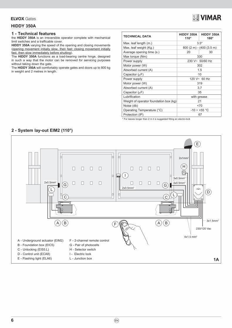
2 - System lay-out EIM2 (110°)
1 - Technical featuresthe HIDDY 350A is an irreversible operator complete with mechanical limit switches and a trafficable cover.HIDDY 350A varying the speed of the opening and closing movements (opening movement initially slow, then fast; closing movement initially fast, then slow immediately before shutting).The HIDDY 350A functions as a load-bearing centre hinge, designed in such a way that the motor can be removed for servicing purposes without taking down the gate.The HIDDY 350A will comfortably operate gates and doors up to 800 kg in weight and 2 metres in length.
TECHNICAL DATA HIDDY 350A110°
HIDDY 350A180°
Max. leaf length (m.) 3.5*Max. leaf weight (Kg.) 800 (2 m) - (400 (3.5 m)Average opening time (s.) 20 30Max torque (Nm) 330Power supply 230 V~ 50/60 HzMotor power (W) 302Absorbed current (A) 1.5Capacitor (µF) 10Power supply 120 V~ 60 HzMotor power (W) 319Absorbed current (A) 3,7Capacitor (µF) 35Lubrification with greaseWeight of operator foundation box (kg) 21Noise (db) <70Operating Temperature (°C) -10 ÷ +55 °CProtection (IP) 67
* For leaves longer than 2 m it is suggested fitting an electro-lock
A B
C
LG
I
F
E
A B
G
L
H
D2x0.5mm2
4x1.5 mm2
2x0.5mm2 4x0.5mm2
3x0.5mm2
2x1mm2
3x1.5mm2
230/120 Vac
C
A - Underground actuator (EIM2) F - 2-channel remote controlB - Foundation box (EIC5) G - Pair of photocellsC - Unlocking (EIS5.L) H - Selector switchD - Control unit (ECA8) I - Electric lockE - Flashing light (ELA6) L - Junction box 1A
7
HIDDY 350A
EN
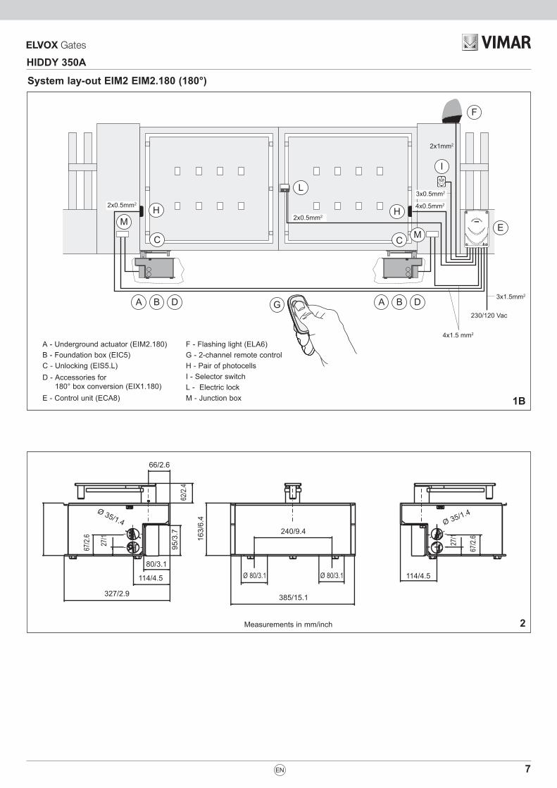
System lay-out EIM2 EIM2.180 (180°)
Measurements in mm/inch
A B
C
MH
L
G
F
A B
H
M
I
E2x0.5mm2
4x1.5 mm2
2x0.5mm2 4x0.5mm2
3x0.5mm2
2x1mm2
3x1.5mm2
230/120 Vac
C
A - Underground actuator (EIM2.180) F - Flashing light (ELA6)B - Foundation box (EIC5) G - 2-channel remote controlC - Unlocking (EIS5.L) H - Pair of photocellsD - Accessories for
180° box conversion (EIX1.180)I - Selector switchL - Electric lock
E - Control unit (ECA8) M - Junction box
D D
1B
2
114/4.5
Ø 35/1.4Ø 35/1.4
Ø 80/3.1 Ø 80/3.1
385/15.1327/2.9
240/9.4
163/
6.4
62/2.
495
/3.7
27/1
67/2.
6
67/2.
6
27/1
66/2.6
80/3.1
114/4.5

8
HIDDY 350A
EN
250
460 380
3 - Installation
3.1 - Pre-installation checksThe leaf must be fixed firmily on the hinges to the pillars, must not be flexible during the movement and must move without frictions.Before the installation of HIDDY 350A, verify all dimensions etc.There’s no need for any modification, if the gate is like that shown in Fig. 1.Gate features must be uniformed with the standards and laws in force. The gate can be automated only if it is in a good condition and its conditions comply with the EN 12604 norm.- The gate leaf does not have to have a pedestrian opening. In the
opposite case it is necessary to take the appropriate steps, in accordance with EN 12453 norm (for instance; by preventing the operation of the motor when the pedestrian opening is opened, by installing a safety microswitch connected with the control panel).
- No mechanical stop shall be on top of the gate, since mechanical stops are not safe enough.
3.2 - Prepare the cementation of the box- Excavate a trench next to the pillar (Fig. 3).- On the bottom of foundation box a 50 mm Ø pipe should be fitted to
drain water. On one side of the box another pipe 32 mm Ø should be fitted. Pipe should be flexible, sturdy and insulated type, to let out electrical wiring (use holes on internal side of gate opening).ENSURE THAT THE CABLE JOINTS ARE MADE inside a sealed junction box OUTSIDE.
- Use a level to position the box so that the upper edge of the cover corresponds with the finished floor level.
- The centreline of the pintles must be perfectly in line with the centreline of the operating arm mounting shaft.
- For HIDDY 350 110° (EIM2): Cement in, taking care to ensure that cement does not fall into the box and checking that the short sides of the box are perfectly parallel to the gate when in the “CLOSED” position.
- For HIDDY 350 180° (EIM2.180): Cement in, taking care to ensure that cement does not fall into the box and checking that the short sides of the box are perfectly perpendicular to the gate when in the “CLOSED” position.
- Insert the bolts for cover fixing in places cut into the foundation box.
Tube for electric cables
Tube for water drain
Tube for water drain
Tube for electric cables
3
4
5

9
HIDDY 350A
EN
SX DX
FE E
DXSX
2 2A A
B 1 B 1
C
B
A
F
D
DXSX
2 2A A
B 1 B 1
C
B
A
F
D
GATE SHUT GATE SHUT
3.3 - Installing HIDDY 350A 110° (EIM2)- Make sure that the pivot of foundation box is well greased. Lay down the
ball (A) end insert drive rod (B) after fitting release system (picture 6).- Fit gate bracket plate (C) through its pivot in the drive rod (B) (picture 6).- Place gate leaf between upper hinge and plate of gate bracket (hinge
and pivot of gate bracket plate should be perfectly aligned).- Weld carefully bracket plate (C) on the leaf.- Fit adjusting open position bolt (D) (picture 7) M10X30 and relevant nut.- Fit EIM2 operator inside the foundation box (picture 7).- Screw on pulling lever (B) adjusting bolt M10x60 (E) and relevant nut
(picture 7).- Fit joint lever (F) (picture 7).- ATTENTION: joint lever (F) must be fitted as shown in picture 7.
Should it be difficoult to fit, operate electrically the reducer.
3.4 - Installing HIDDY 350A 180° (EIM2.180)- Make sure that the pivot of foundation box is well greased. Lay down
the ball (A) end insert drive rod (B) after fitting release system.- Fit gate bracket plate (C) through its pivot in the drive rod (B).- Place gate leaf between upper hinge and plate of gate bracket (hinge
and pivot of gate bracket plate should be perfectly aligned).- Weld carefully bracket plate (C) on the leaf.- Fit EIM2 operator inside foundation box (picture 8) by means of en-
closed nuts M12 and washers on column side, while on opposite col-umn side screw in “prolunghe” and relevant washers (refer to exploded view at last page).
ATTENTION: EIM2 motor must be always placed as in picture 8 (motor on right side), no matter right or left side.- Fit gearing plate by means of relevant nuts and washers M10.- Insert bolt and nut for adjusting (A) (Picture 8).- Insert gear train into splined drive shaft, after fitting adjusting bolt (B)
as in (picture 8).ATTENTION: adjusting of opening travel must be done by adjusting bolt (A), but amplitude is regulated by position of insertion of drive shaft. The wider the opening is needed the closer to stop 1 it must be inserted (for left side fitting), or stop 2 (for right side fitting).
6
7
8
10
HIDDY 350A
C C
EN
Yellow- Green
Blue
Brown
Black
Common Common
B
EIS5.L
3.5 - Adjustment of HIDDY 350A 110° (EIM2) mechanical stopperThe HIDDY 350A system requires no floor stops or other accessories as the gate travel limit is determined by means of set screws located internally of the box. Access to the screws is gained by lifting the cover.- To adjust the travel limit for the opening movement of the gate, simply
turn the screw (D) left or right as appropriate, then secure the lock nut to prevent the screw from slipping out of position subsequently (Fig. 6).
Same adjusting must be done also on bolt (E) for closing, in order to let the mechanism block again when unblocked (Fig. 7).
IMPORTANT: Please make sure that the leaves stop against the mechanical stoppers inside the operator before they reached the ground mechanical stopper. In not adjusted, unblocking will be impossible.
3.6 - Electrical connectionTo be undertaken after disconnecting the power supply to the engine control unit.Refer to the directions of Fig. 11.
3.7 - Emergency releaseTo be carried out after having disconnected the power supply to the motor.In order to carry out the manual operation of the gate leaf the followings must be checked:- That the physical effort necessary to move the gate leaf should not be
higher than (values indicated of the EN 12453 norm) .In the case of a power cut, the gate can be opened manually by releasing the lock on the operating lever to allow the gate to move freely.
IMPORTANT: Please make sure that the leaves stop against the mechanical stoppers inside the operator before they reached the ground mechanical stopper. In not adjusted, unblocking will be impossible.
3.8 - Safety clutch adjustmentThere is no mechanical safety clutch with the HIDDY 350A.Therefore it is necessary to operate this operator with an electronic control panel fitted with an electronic force regulator. Use the ECA8 (for one or two single-phase motors) electronic control unit.
3.9 - Adjustment of HIDDY 350A 180° (EIM2.180) mechanical stopperTo adjust the travel limits to the required positions, simply turn the relative screws A and B left or right as appropriate, then secure the locks nuts to prevent the screws from slipping out of position subsequently (Fig. 8).Before this adjustment is made, the angular position of the stop must be selected according to the maximum opening arc required:A = CLOSING STOPAdjusting must be done in order to let the mechanism block again when unblocked.B = OPENING STOP
ATTENTION: further to adjusting opening bolt, it is necessary to insert drive shaft approximately towards the stop where adjusting bolt will end (2 for left side and 1 for right side).
IMPORTANT: Please make sure that the leaves stop against the mechanical stoppers inside the operator before they reached the ground mechanical stopper. In not adjusted, unblocking will be impossible.
3.10 - Electrical safety devices The installation must be installed according to the current regulations and laws. Use the ECA8 (for one or two single-phase motors) electronic control unit. For connections and technical data of accessories refer to the appropriate booklets.
3.11 - MaintenanceTo be undertaken by specialized staff after disconnecting power supply.
9
10
11
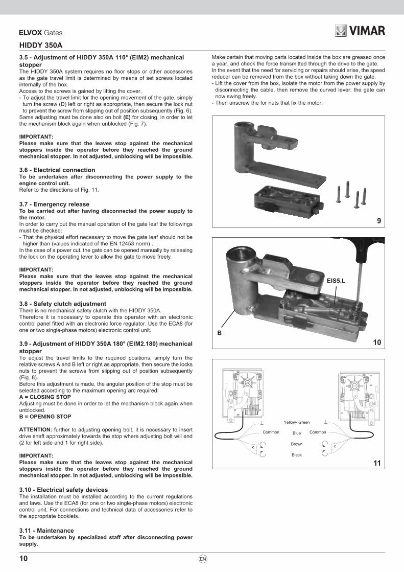
Make certain that moving parts located inside the box are greased once a year, and check the force transmitted through the drive to the gate.In the event that the need for servicing or repairs should arise, the speed reducer can be removed from the box without taking down the gate.- Lift the cover from the box, isolate the motor from the power supply by
disconnecting the cable, then remove the curved lever: the gate can now swing freely.
- Then unscrew the for nuts that fix the motor.
11
HIDDY 350A
EC DECLARATION OF CONFORMITY(Declaration of incorporation of partly completed machinery annex IIB Directive 2006/42/EC)
No. : ZDT00445.0
The undersigned, representing the following manufacturer Vimar SpA
Viale Vicenza 14 36063 Marostica VI
Italy
herewith declares that the products
ACTUATORS FOR GATES WITH SWING DOORS - SERIES HIDDY
ArticlesHIDDY 350A
are in conformity with the provisions of the following EC directive(s) (including all applicable amendments) and that the following standards and/or technical specifications have been applied:
LV Directive 2006/95/EC: EN 60335-2-103 (2003) + A11 (2009)EMC Directive 2004/108/EC: EN 61000-6-1 (2007), EN 61000-6-3 (2007) + A1 (2011), EN 61000-6-2 (2005), EN 61000-6-4 (2007) + A1 (2011)Machinery Directive 2006/42/EC EN 13241 (2003) + A1 (2011), EN 12453 (2000)
Further hereby declares that the product must not be put into service until the final machinery into which it is to be incor-porated has been declared in conformity with the provisions of Directive 2006/42/EC, where appropriate.
Declares that the relevant technical documentation has been compiled by Vimar SpA in accordance with part B of Annex VII of Directive 2006/42/EC and that the following essential requirements of this Directive have been applied and fulfilled: 1.1.1, 1.1.2, 1.1.3, 1.1.5, 1.1.6, 1.2.1, 1.2.2, 1.2.6, 1.3.1, 1.3.2, 1.3.3, 1.3.4, 1.3.7, 1.3.8, 1.3.9, 1.4.1, 1.4.2, 1.5.1, 1.5.2, 1.5.4, 1.5.5, 1.5.6, 1.5.7, 1.5.8, 1.5.9, 1.6.1., 1.6.2, 1.7.1, 1.7.2, 1.7.3, 1.7.4.
I undertake to make available, in response to a reasoned request by the national authorities, any further supporting pro-duct documents they require.
Marostica, 04/12/2017
The Managing Director
Note: The contents of this declaration correspond to what declared in the last revision of the official declaration available before printing this manual. The text herein has been re-edited for editorial purposes. A copy of the original declaration can be requested to Vimar SpA.
EN

12
HIDDY 350A

13
HIDDY 350A

Viale Vicenza, 1436063 Marostica VI - Italy
www.vimar.com49401101A0 03 1810