46535 - download.vimar.com · 3.2 Funzioni base ... 3.4 Funzionamento schermo testuale ......
28
Manuale per il collegamento e l’uso Installation and operation manual 46535.010B Telecamera Mini Speed Dome 10X AHD 2Mpx IR 50m 10X AHD 2Mpx IR 50m Mini Speed Dome Camera
Transcript of 46535 - download.vimar.com · 3.2 Funzioni base ... 3.4 Funzionamento schermo testuale ......

Manuale per il collegamento e l’usoInstallation and operation manual
46535.010B Telecamera Mini Speed Dome 10X AHD 2Mpx IR 50m
10X AHD 2Mpx IR 50m Mini Speed Dome Camera
2
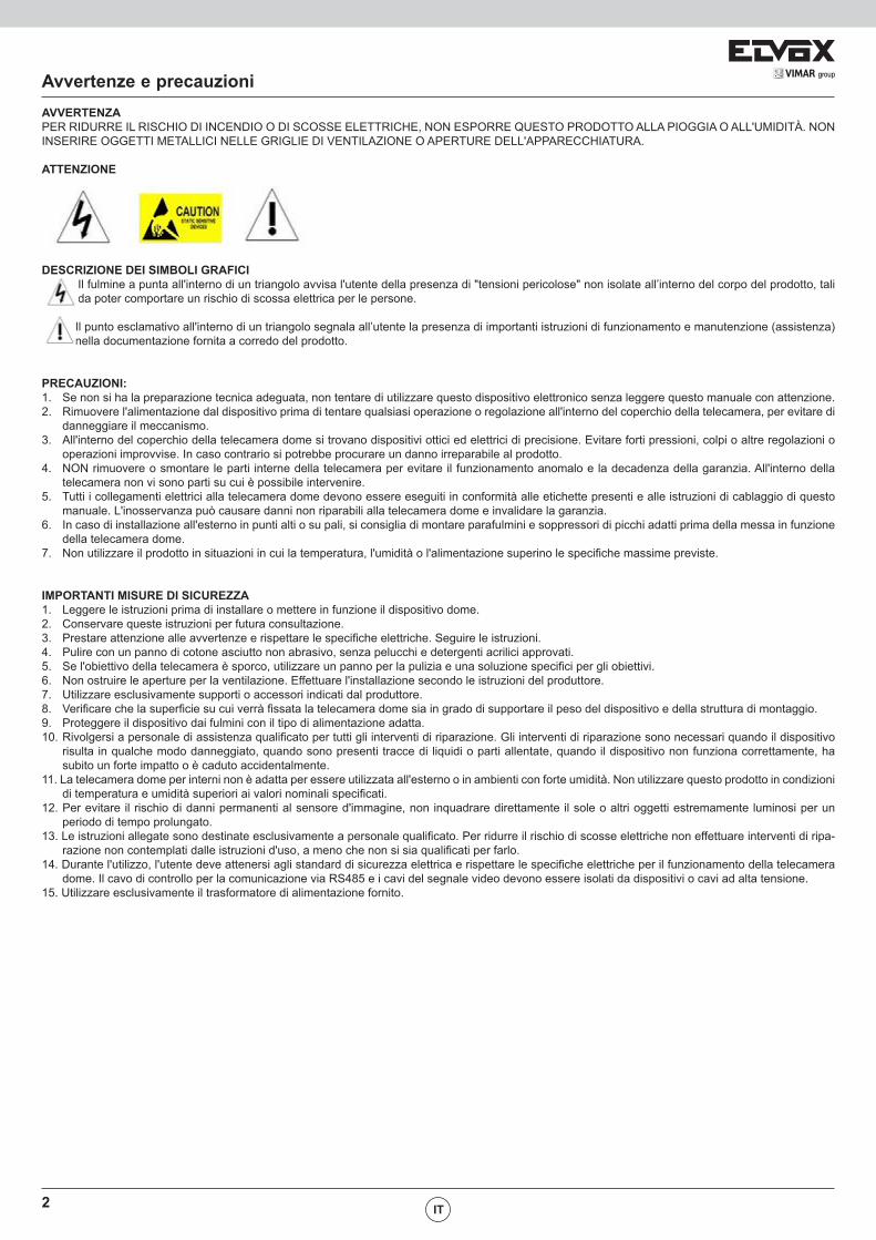
AVVERTENZAPER RIDURRE IL RISCHIO DI INCENDIO O DI SCOSSE ELETTRICHE, NON ESPORRE QUESTO PRODOTTO ALLA PIOGGIA O ALL'UMIDITÀ. NON INSERIRE OGGETTI METALLICI NELLE GRIGLIE DI VENTILAZIONE O APERTURE DELL'APPARECCHIATURA.
ATTENZIONE
Avvertenze e precauzioni
DESCRIZIONE DEI SIMBOLI GRAFICIIl fulmine a punta all'interno di un triangolo avvisa l'utente della presenza di "tensioni pericolose" non isolate all’interno del corpo del prodotto, tali da poter comportare un rischio di scossa elettrica per le persone.
Il punto esclamativo all'interno di un triangolo segnala all’utente la presenza di importanti istruzioni di funzionamento e manutenzione (assistenza) nella documentazione fornita a corredo del prodotto.
PRECAUZIONI:1. Se non si ha la preparazione tecnica adeguata, non tentare di utilizzare questo dispositivo elettronico senza leggere questo manuale con attenzione. 2. Rimuovere l'alimentazione dal dispositivo prima di tentare qualsiasi operazione o regolazione all'interno del coperchio della telecamera, per evitare di
danneggiare il meccanismo.3. All'interno del coperchio della telecamera dome si trovano dispositivi ottici ed elettrici di precisione. Evitare forti pressioni, colpi o altre regolazioni o
operazioni improvvise. In caso contrario si potrebbe procurare un danno irreparabile al prodotto.4. NON rimuovere o smontare le parti interne della telecamera per evitare il funzionamento anomalo e la decadenza della garanzia. All'interno della
telecamera non vi sono parti su cui è possibile intervenire.5. Tutti i collegamenti elettrici alla telecamera dome devono essere eseguiti in conformità alle etichette presenti e alle istruzioni di cablaggio di questo
manuale. L'inosservanza può causare danni non riparabili alla telecamera dome e invalidare la garanzia.6. In caso di installazione all'esterno in punti alti o su pali, si consiglia di montare parafulmini e soppressori di picchi adatti prima della messa in funzione
della telecamera dome.7. Non utilizzare il prodotto in situazioni in cui la temperatura, l'umidità o l'alimentazione superino le specifiche massime previste.
IMPORTANTI MISURE DI SICUREZZA1. Leggere le istruzioni prima di installare o mettere in funzione il dispositivo dome.2. Conservare queste istruzioni per futura consultazione.3. Prestare attenzione alle avvertenze e rispettare le specifiche elettriche. Seguire le istruzioni.4. Pulire con un panno di cotone asciutto non abrasivo, senza pelucchi e detergenti acrilici approvati.5. Se l'obiettivo della telecamera è sporco, utilizzare un panno per la pulizia e una soluzione specifici per gli obiettivi.6. Non ostruire le aperture per la ventilazione. Effettuare l'installazione secondo le istruzioni del produttore.7. Utilizzare esclusivamente supporti o accessori indicati dal produttore.8. Verificare che la superficie su cui verrà fissata la telecamera dome sia in grado di supportare il peso del dispositivo e della struttura di montaggio.9. Proteggere il dispositivo dai fulmini con il tipo di alimentazione adatta.10. Rivolgersi a personale di assistenza qualificato per tutti gli interventi di riparazione. Gli interventi di riparazione sono necessari quando il dispositivo
risulta in qualche modo danneggiato, quando sono presenti tracce di liquidi o parti allentate, quando il dispositivo non funziona correttamente, ha subito un forte impatto o è caduto accidentalmente.
11. La telecamera dome per interni non è adatta per essere utilizzata all'esterno o in ambienti con forte umidità. Non utilizzare questo prodotto in condizioni di temperatura e umidità superiori ai valori nominali specificati.
12. Per evitare il rischio di danni permanenti al sensore d'immagine, non inquadrare direttamente il sole o altri oggetti estremamente luminosi per un periodo di tempo prolungato.
13. Le istruzioni allegate sono destinate esclusivamente a personale qualificato. Per ridurre il rischio di scosse elettriche non effettuare interventi di ripa-razione non contemplati dalle istruzioni d'uso, a meno che non si sia qualificati per farlo.
14. Durante l'utilizzo, l'utente deve attenersi agli standard di sicurezza elettrica e rispettare le specifiche elettriche per il funzionamento della telecamera dome. Il cavo di controllo per la comunicazione via RS485 e i cavi del segnale video devono essere isolati da dispositivi o cavi ad alta tensione.
15. Utilizzare esclusivamente il trasformatore di alimentazione fornito.
IT
1VIMAR group
SommarioINDICE1 Presentazione del prodotto ....................................................................................................................................................................................2 1.1 Specifiche ............................................................................................................................................................................................................2 1.2 Descrizione delle funzioni ....................................................................................................................................................................................22 Installazione..................................................................................................................... .......................................................................................4 2.1 Dimensioni del prodotto .......................................................................................................................................................................................43. Istruzioni di funzionamento ....................................................................................................................................................................................5 3.1 Operazioni all'accensione ....................................................................................................................................................................................5 3.2 Funzioni base ......................................................................................................................................................................................................5 3.3 Comandi a scelta rapida ......................................................................................................................................................................................5 3.4 Funzionamento schermo testuale .......................................................................................................................................................................54 Menu OSD .................................................................................................................................................................................................................6 4.1 Indice dei menu ...................................................................................................................................................................................................6 4.2 Informazioni di sistema ........................................................................................................................................................................................7 4.3 Dome ...................................................................................................................................................................................................................7 4.3.1 Comunicazioni .........................................................................................................................................................................................7 4.3.2 IR .............................................................................................................................................................................................................8 4.3.3 Giri di sorveglianza ..................................................................................................................................................................................8 4.3.4 Scansione A-B .........................................................................................................................................................................................8 4.3.5 Scansione Pan .........................................................................................................................................................................................8 4.3.6 Pattern ....................................................................................................... .............................................................................................9 4.3.7 Azione parcheggio ...................................................................................................................................................................................9 4.3.8 Impostazioni avanzate .............................................................................................................................................................................9 4.4 Telecamera ...........................................................................................................................................................................................................9 4.5 Display ................................................................................................................................................................................................................10 4.6 Lingua .................................................................................................................................................................................................................10 4.7 Attività programmata...........................................................................................................................................................................................10 4.8 Allarme................................................................................................................................................................................................................10 4.9 Reset .................................................................................................................................................................................................................. 115. Controllo automatico della temperatura ............................................................................................................................................................. 11Appendice 1 - Protezione contro i fulmini e sovratensione ..................................................................................................................................12Appendice 2 - Pulizia del coperchio trasparente....................................................................................................................................................12Appendice 3 - Informazioni sul bus RS-485 ............................................................................................................................................................12 1. Funzioni di base del bus RS-485 ........................................................................................................................................................................12 2. Modalità di collegamento e resistenza di terminazione ......................................................................................................................................12
IT
2
1 Presentazione del prodotto
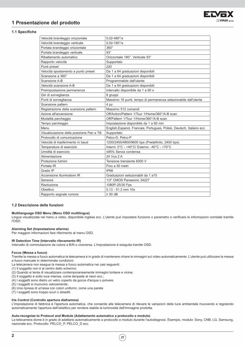
1.1 SpecificheVelocità brandeggio orizzontale 0,02-480°/sVelocità brandeggio verticale 0,02-160°/sPortata brandeggio orizzontale 360°Portata brandeggio verticale 93°Ribaltamento automatico Orizzontale 180°, Verticale 93°Rapporto velocità SupportatoPunti preset 220Velocità spostamento a punto preset Da 1 a 64 graduazioni disponibiliScansione a 360° Da 1 a 64 graduazioni disponibiliScansione A-B Programmabile dall'utenteVelocità scansione A-B Da 1 a 64 graduazioni disponibiliPreimpostazione permanenza Intervallo disponibile da 1 a 60 sGiri di sorveglianza 8 gruppiPunti di sorveglianza Massimo 16 punti, tempo di permanenza selezionabile dall'utenteScansione pattern 4 pz.Registrazione della scansione pattern Massimo 512 comandiAzione all'accensione Off/Action/Pattern 1/Tour 1/Home/360°/A-B scanModalità parcheggio Off/Pattern 1/Tour 1/Home/360°/A-B scanTempo parcheggio Impostazione disponibile da 1 a 60 minMenu English,Espanol, Francais, Portugues, Polski, Deutsch, Italiano ecc.Visualizzazione della posizione Pan e Tilt SupportatoProtocollo di comunicazione Pelco-D, Pelco-PVelocità di trasferimento in baud 1200/2400/4800/9600 bps (Predefinito, 2400 bps)Temperatura di esercizio Interni: 0°C - +40°C/ Esterno: -40°C - +70°CUmidità di esercizio ≤95% Senza condensaAlimentazione 24 Vca 2 AProtezione fulmini Tensione transiente 6000 VPortata IR Fino a 50 metriGrado IP IP66Accensione illuminatore IR Graduazioni selezionabili da 1 a15Sensore 1/3" CMOS Panasonic 34227Risoluzione 1080P-25/30 FpsObiettivo 5,13 - 51,3 mm 10xRapporto segnale rumore ≥ 50 dB
1.2 Descrizione delle funzioni
Multilanguage OSD Menu (Menu OSD multilingua)Lingua visualizzata nel menu a video, disponibile inglese ecc. L'utente può impostare funzione o parametro o verificare le informazioni correlate tramite l'OSD.
Alarming Set (Impostazione allarme)Per maggiori informazioni fare riferimento al menu OSD.
IR Detection Time (Intervallo rilevamento IR)Intervallo di commutazione da colore a B/N o viceversa. L'impostazione è eseguita tramite OSD.
Focus (Messa a fuoco)Tramite la messa a fuoco automatica la telecamera è in grado di mantenere chiare le immagini sul video automaticamente. L'utente può utilizzare la messa a fuoco manuale in determinate condizioni.La telecamera non esegue la messa a fuoco automatica nei casi seguenti:(1) Il soggetto non è al centro dello schermo;(2) Quando si tenta di visualizzare contemporaneamente immagini lontane e vicine;(3) Il soggetto è sotto luce intensa, come lampade al neon ecc.;(4) I soggetti sono dietro un vetro coperto da gocce d'acqua o polvere;(5) I soggetti si muovono velocemente;(6) Una ripresa di un'area con colori uniformi, come una parete (7) I soggetti sono troppo scuri o sbiaditi.
Iris Control (Controllo apertura diaframma)L'impostazione di fabbrica è l'apertura automatica, che consente alla telecamera di rilevare le variazioni della luce ambientale muovendo e regolando automaticamente l'apertura dell'obiettivo per rendere stabile la luminosità dell'immagine prodotta.
Auto-recognize to Protocol and Module (Adattamento automatico a protocollo e modulo)La telecamera dome è in grado di adattarsi automaticamente a protocollo e modulo durante l'autodiagnosi. Esempio, modulo: Sony, CNB, LG, Samsung, nazionale ecc. Protocollo: PELCO_P, PELCO_D ecc.
IT
3VIMAR group
1 Presentazione del prodottoDay/Night Switch (Commutazione Giorno/Notte)La funzione di commutazione automatica giorno/notte consente la commutazione automatica dell'immagine dalla modalità giorno alla modalità notte quando l'illuminazione è debole e viceversa quando l'illuminazione è forte.
Ratio Speed (Rapporto velocità)La velocità di brandeggio orizzontale e verticale intelligente varia in funzione del fattore di zoom. Con zoom avanti "X10", la velocità si riduce, con zoom indietro "X1", la velocità aumenta.
A-B Scan (Scansione A-B)La telecamera dome effettua la scansione circolare dettagliata in tempo reale della scena, sia in senso orizzontale che verticale, in base ai punti A e B e alla velocità impostata.
Pan Scan (Scansione pan)La telecamera dome effettua scansioni continue della scena visualizzata con una rotazione orizzontale di 360° in senso orario a una velocità impostata e con angolo di inclinazione costante.
PresetDopo avere preregolato una certa posizione PTZ, la telecamera dome si sposta automaticamente alla posizione impostata quando viene richiamato il preset.
Guard Tour Scan (Scansione giro di sorveglianza)La funzione di ronda della telecamera dome effettua la scansione in base a un ordine preimpostato.
Power Off Memory (Memoria spegnimento)Questa funzione consente alla telecamera dome di recuperare il preset o lo stato precedente al ripristino dell'alimentazione. Per impostazione predefinita, la telecamera dome supporta una memoria alimentata, che migliora l'affidabilità ed evita di dover reimpostare ripetutamente i parametri.
Park Action (Azione di parcheggio)Se la telecamera dome non viene utilizzata per un intervallo di tempo definito, eseguirà automaticamente una modalità specifica preimpostata (scansione pan, scansione A-B, azione parcheggio, cruise, preserve action ecc.).
Zero Alignment (Allineamento a zero)Esiste un punto definito punto zero. Quando la telecamera dome è in funzione e il punto preset non è preciso a causa di un errore dell'operatore, l'utente può effettuare automaticamente l'allineamento a zero della telecamera dome mediante un ordine operativo.
Auto Flip (Ribaltamento automatico)Nella modalità di inseguimento manuale, quando il soggetto passa direttamente sotto la telecamera, questa ruota automaticamente di 180 gradi in dire-zione orizzontale per continuare a seguirlo. Quando la telecamera dome si ribalta, inizia a muoversi verso l'alto fintanto che si continua a tenere il joystick in posizione abbassata.
IT
4
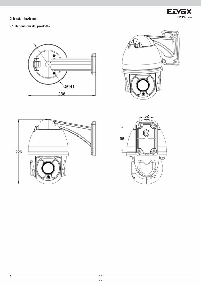
2.1 Dimensioni del prodotto
2 Installazione
IT
5VIMAR group
3 Istruzioni di funzionamento
3.1 Operazioni all'accensione
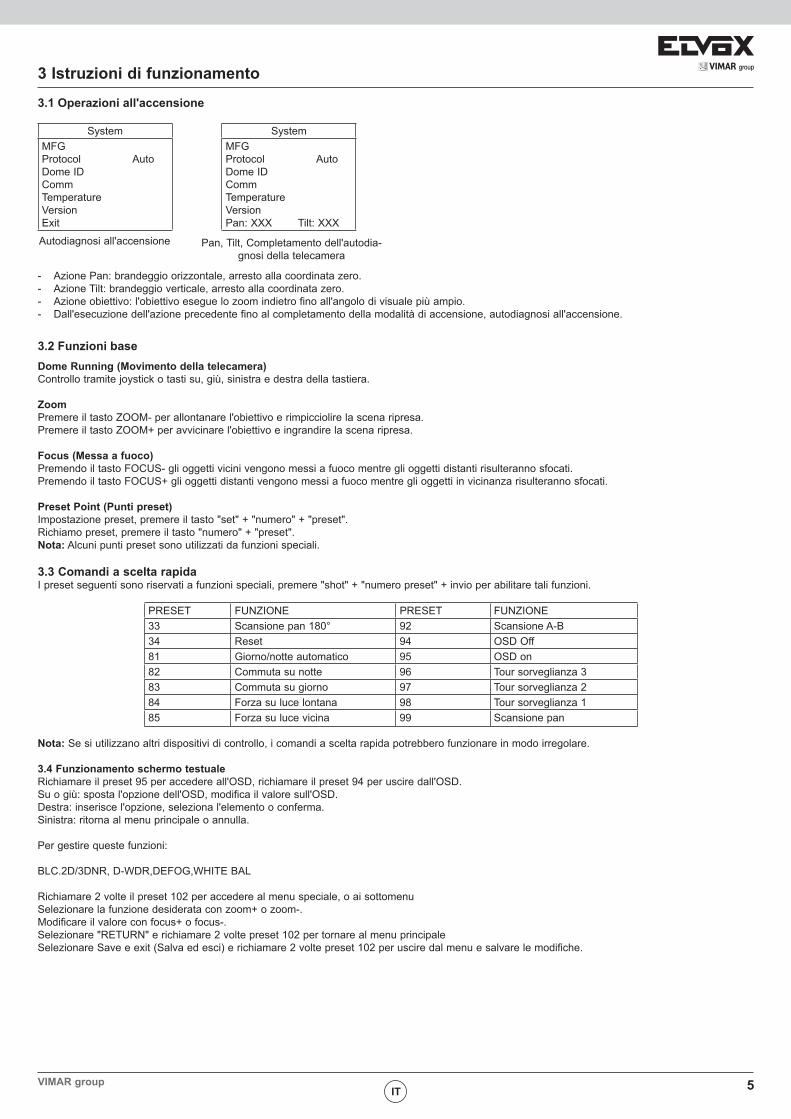
SystemMFGProtocol AutoDome IDCommTemperatureVersionExit
SystemMFGProtocol AutoDome IDCommTemperatureVersionPan: XXX Tilt: XXX
Autodiagnosi all'accensione Pan, Tilt, Completamento dell'autodia-gnosi della telecamera
- Azione Pan: brandeggio orizzontale, arresto alla coordinata zero.- Azione Tilt: brandeggio verticale, arresto alla coordinata zero.- Azione obiettivo: l'obiettivo esegue lo zoom indietro fino all'angolo di visuale più ampio.- Dall'esecuzione dell'azione precedente fino al completamento della modalità di accensione, autodiagnosi all'accensione.
3.2 Funzioni baseDome Running (Movimento della telecamera)Controllo tramite joystick o tasti su, giù, sinistra e destra della tastiera.
ZoomPremere il tasto ZOOM- per allontanare l'obiettivo e rimpicciolire la scena ripresa.Premere il tasto ZOOM+ per avvicinare l'obiettivo e ingrandire la scena ripresa.
Focus (Messa a fuoco)Premendo il tasto FOCUS- gli oggetti vicini vengono messi a fuoco mentre gli oggetti distanti risulteranno sfocati. Premendo il tasto FOCUS+ gli oggetti distanti vengono messi a fuoco mentre gli oggetti in vicinanza risulteranno sfocati.
Preset Point (Punti preset)Impostazione preset, premere il tasto "set" + "numero" + "preset".Richiamo preset, premere il tasto "numero" + "preset".Nota: Alcuni punti preset sono utilizzati da funzioni speciali.
3.3 Comandi a scelta rapidaI preset seguenti sono riservati a funzioni speciali, premere "shot" + "numero preset" + invio per abilitare tali funzioni.
PRESET FUNZIONE PRESET FUNZIONE33 Scansione pan 180° 92 Scansione A-B34 Reset 94 OSD Off81 Giorno/notte automatico 95 OSD on82 Commuta su notte 96 Tour sorveglianza 383 Commuta su giorno 97 Tour sorveglianza 284 Forza su luce lontana 98 Tour sorveglianza 185 Forza su luce vicina 99 Scansione pan
Nota: Se si utilizzano altri dispositivi di controllo, i comandi a scelta rapida potrebbero funzionare in modo irregolare.
3.4 Funzionamento schermo testualeRichiamare il preset 95 per accedere all'OSD, richiamare il preset 94 per uscire dall'OSD. Su o giù: sposta l'opzione dell'OSD, modifica il valore sull'OSD.Destra: inserisce l'opzione, seleziona l'elemento o conferma.Sinistra: ritorna al menu principale o annulla.
Per gestire queste funzioni:
BLC.2D/3DNR, D-WDR,DEFOG,WHITE BAL
Richiamare 2 volte il preset 102 per accedere al menu speciale, o ai sottomenuSelezionare la funzione desiderata con zoom+ o zoom-.Modificare il valore con focus+ o focus-.Selezionare "RETURN" e richiamare 2 volte preset 102 per tornare al menu principaleSelezionare Save e exit (Salva ed esci) e richiamare 2 volte preset 102 per uscire dal menu e salvare le modifiche.
IT

6 IT
4 Menu OSD
IT
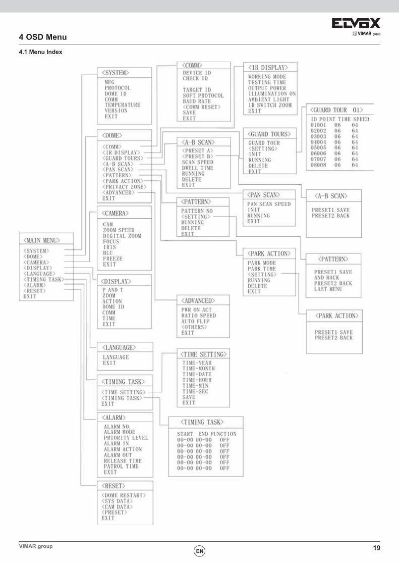
4.1 Indice dei menu
7VIMAR groupIT
4 Menu OSD
IT
4.2 Informazioni di sistema
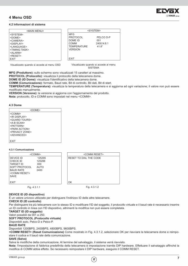
<MAIN MENU><SYSTEM><DOME><CAMERA><DISPLAY><LANGUAGE><TIMING TASK><ALARM><RESET> EXIT
<SYSTEM>MFGPROTOCOL PELCO D-PDOME ID 001COMM 2400.N.8.1TEMPERATURE 41.8°VERSION
EXIT
Visualizzato quando si accede al menu OSD Visualizzato quando si accede al menu SISTEMA
MFG (Produttore): sullo schermo sono visualizzati 15 caratteri al massimo.PROTOCOL (Protocollo): visualizza il protocollo della telecamera dome.DOME ID (ID Dome): visualizza l'identificativo della telecamera dome.COMM (Comunicazione): formato, Baud rate, Bit di controllo, Bit dati, Bit di start.TEMPERATURE (Temperatura): visualizza la temperatura della telecamera e si aggiorna ad ogni variazione; il valore non può essere modificato manualmente.VERSION (Versione): la versione si aggiorna con l'aggiornamento del prodotto.Nota: protocollo, ID e COMM sono impostati nel menu <COMM>.
4.3 Dome<DOME>
<COMM><IR DISPLAY><GUARD TOURS><A-B SCAN><PATTERN><PARK ACTION><PRIVACY ZONE><ADVANCED>
EXIT
4.3.1 Comunicazione
<COMM>DEVICE ID 125295CHECK ID 125288TARGET ID 000SOFT PROTOCOL AUTOBAUD RATE 2400<COMM RESET>SAVE
EXIT
<COMM RESET>RESET TO DIAL THE CODE
OK
Fig. 4.3.1.1 Fig. 4.3.1.2
DEVICE ID (ID dispositivo)È un valore univoco utilizzato per distinguere l'indirizzo ID delle altre telecamere.CHECK ID (ID controllo)Per distinguere tra più telecamere con lo stesso ID e modificare l'ID del soggetto, il protocollo virtuale e il baud rate è necessario inserire un ID controllo in linea con l'ID dispositivo, altrimenti la modifica non può essere completata.TARGET ID (ID soggetto)Valori possibili da 001 a 250.SOFT PROTOCOL (Protocollo virtuale)Disponibili auto, Pelco-D e Pelco-P.BAUD RATEDisponibili 1200BPS, 2400BPS, 4800BPS, 9600BPS.<COMM RESET> (Reset Comunicazione) Come mostrato in Fig. 4.3.1.2, selezionare OK per riavviare la telecamera dome e reimpo-stare il codice e il baud rate della comunicazione.SAVE (Salva)Salva le modifiche della comunicazione. Al termine del salvataggio, il sistema verrà riavviato.Nota: l'impostazione di fabbrica predefinita della telecamera è impostazione tramite DIP hardware. Effettuare il salvataggio affinché la modifica di COMM abbia effetto. Se necessario reimpostare il DIP hardware, eseguire il COMM RESET.
8
4 Menu OSD4.3.2 IR
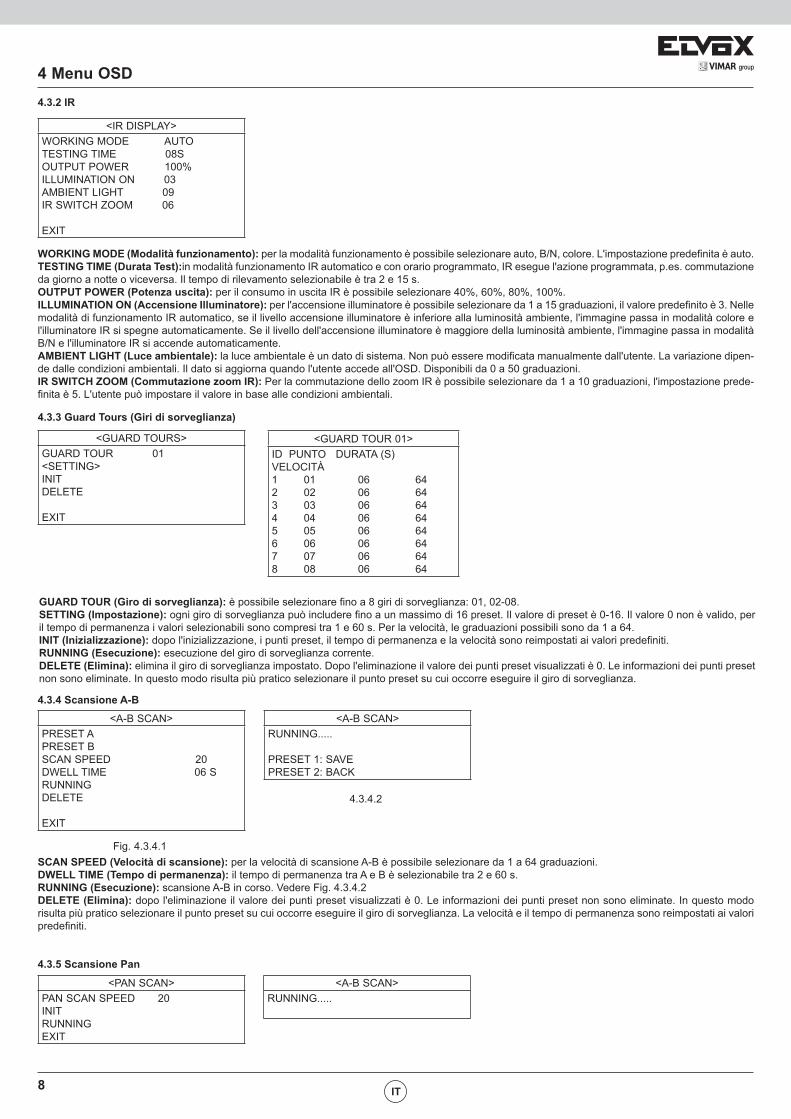
<IR DISPLAY>WORKING MODE AUTOTESTING TIME 08SOUTPUT POWER 100%ILLUMINATION ON 03AMBIENT LIGHT 09IR SWITCH ZOOM 06
EXIT
WORKING MODE (Modalità funzionamento): per la modalità funzionamento è possibile selezionare auto, B/N, colore. L'impostazione predefinita è auto.TESTING TIME (Durata Test):in modalità funzionamento IR automatico e con orario programmato, IR esegue l'azione programmata, p.es. commutazione da giorno a notte o viceversa. Il tempo di rilevamento selezionabile è tra 2 e 15 s. OUTPUT POWER (Potenza uscita): per il consumo in uscita IR è possibile selezionare 40%, 60%, 80%, 100%.ILLUMINATION ON (Accensione Illuminatore): per l'accensione illuminatore è possibile selezionare da 1 a 15 graduazioni, il valore predefinito è 3. Nelle modalità di funzionamento IR automatico, se il livello accensione illuminatore è inferiore alla luminosità ambiente, l'immagine passa in modalità colore e l'illuminatore IR si spegne automaticamente. Se il livello dell'accensione illuminatore è maggiore della luminosità ambiente, l'immagine passa in modalità B/N e l'illuminatore IR si accende automaticamente. AMBIENT LIGHT (Luce ambientale): la luce ambientale è un dato di sistema. Non può essere modificata manualmente dall'utente. La variazione dipen-de dalle condizioni ambientali. Il dato si aggiorna quando l'utente accede all'OSD. Disponibili da 0 a 50 graduazioni. IR SWITCH ZOOM (Commutazione zoom IR): Per la commutazione dello zoom IR è possibile selezionare da 1 a 10 graduazioni, l'impostazione prede-finita è 5. L'utente può impostare il valore in base alle condizioni ambientali.
4.3.3 Guard Tours (Giri di sorveglianza)
<GUARD TOURS>GUARD TOUR 01<SETTING>INITDELETE
EXIT
GUARD TOUR (Giro di sorveglianza): è possibile selezionare fino a 8 giri di sorveglianza: 01, 02-08.SETTING (Impostazione): ogni giro di sorveglianza può includere fino a un massimo di 16 preset. Il valore di preset è 0-16. Il valore 0 non è valido, per il tempo di permanenza i valori selezionabili sono compresi tra 1 e 60 s. Per la velocità, le graduazioni possibili sono da 1 a 64. INIT (Inizializzazione): dopo l'inizializzazione, i punti preset, il tempo di permanenza e la velocità sono reimpostati ai valori predefiniti.RUNNING (Esecuzione): esecuzione del giro di sorveglianza corrente.DELETE (Elimina): elimina il giro di sorveglianza impostato. Dopo l'eliminazione il valore dei punti preset visualizzati è 0. Le informazioni dei punti preset non sono eliminate. In questo modo risulta più pratico selezionare il punto preset su cui occorre eseguire il giro di sorveglianza.
4.3.4 Scansione A-B
<A-B SCAN>PRESET APRESET BSCAN SPEED 20DWELL TIME 06 SRUNNINGDELETE
EXIT
<A-B SCAN>RUNNING..... PRESET 1: SAVEPRESET 2: BACK
Fig. 4.3.4.1
4.3.4.2
SCAN SPEED (Velocità di scansione): per la velocità di scansione A-B è possibile selezionare da 1 a 64 graduazioni.DWELL TIME (Tempo di permanenza): il tempo di permanenza tra A e B è selezionabile tra 2 e 60 s. RUNNING (Esecuzione): scansione A-B in corso. Vedere Fig. 4.3.4.2DELETE (Elimina): dopo l'eliminazione il valore dei punti preset visualizzati è 0. Le informazioni dei punti preset non sono eliminate. In questo modo risulta più pratico selezionare il punto preset su cui occorre eseguire il giro di sorveglianza. La velocità e il tempo di permanenza sono reimpostati ai valori predefiniti.
4.3.5 Scansione Pan
<PAN SCAN>PAN SCAN SPEED 20INITRUNNINGEXIT
<A-B SCAN>RUNNING.....
IT
<GUARD TOUR 01>ID PUNTO DURATA (S) VELOCITÀ1 01 06 642 02 06 643 03 06 644 04 06 645 05 06 646 06 06 647 07 06 648 08 06 64
9VIMAR group
4 Menu OSDPAN SCAN SPEED (Velocità scansione orizzontale): per la velocità di scansione orizzontale è possibile selezionare da 1 a 64 graduazioni.INIT (Inizializzazione): reimposta la velocità di scansione e il grado di inclinazione ai valori predefiniti.RUNNING (Esecuzione): l'impostazione della velocità di scansione e del grado di inclinazione è in corso.
4.3.6 Pattern
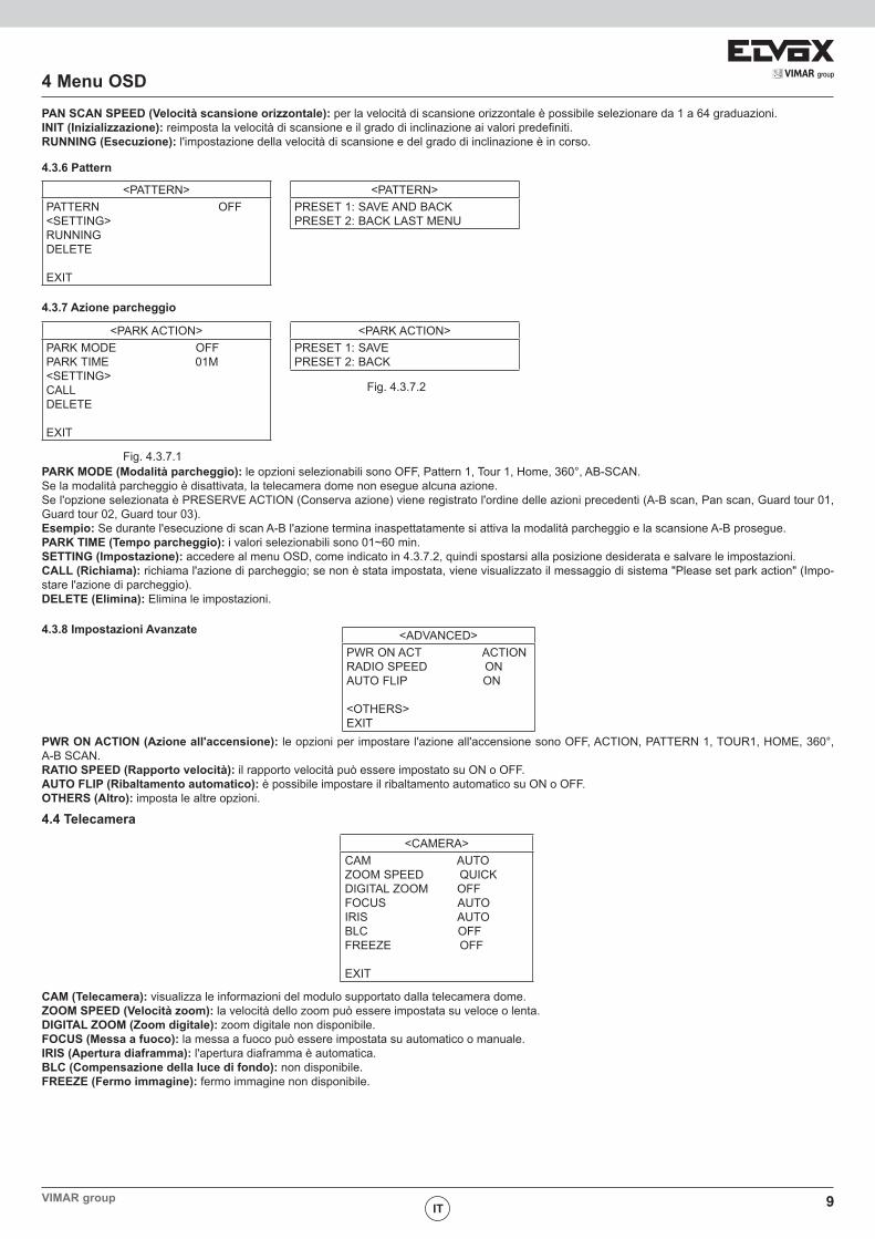
<PATTERN>PATTERN OFF<SETTING>RUNNINGDELETE
EXIT
<PATTERN>PRESET 1: SAVE AND BACKPRESET 2: BACK LAST MENU
<PARK ACTION>PARK MODE OFFPARK TIME 01M<SETTING>CALLDELETE
EXIT
<PARK ACTION>PRESET 1: SAVEPRESET 2: BACK
4.3.7 Azione parcheggio
Fig. 4.3.7.1
Fig. 4.3.7.2
PARK MODE (Modalità parcheggio): le opzioni selezionabili sono OFF, Pattern 1, Tour 1, Home, 360°, AB-SCAN.Se la modalità parcheggio è disattivata, la telecamera dome non esegue alcuna azione.Se l'opzione selezionata è PRESERVE ACTION (Conserva azione) viene registrato l'ordine delle azioni precedenti (A-B scan, Pan scan, Guard tour 01, Guard tour 02, Guard tour 03).Esempio: Se durante l'esecuzione di scan A-B l'azione termina inaspettatamente si attiva la modalità parcheggio e la scansione A-B prosegue.PARK TIME (Tempo parcheggio): i valori selezionabili sono 01~60 min.SETTING (Impostazione): accedere al menu OSD, come indicato in 4.3.7.2, quindi spostarsi alla posizione desiderata e salvare le impostazioni. CALL (Richiama): richiama l'azione di parcheggio; se non è stata impostata, viene visualizzato il messaggio di sistema "Please set park action" (Impo-stare l'azione di parcheggio).DELETE (Elimina): Elimina le impostazioni.
4.3.8 Impostazioni Avanzate <ADVANCED>PWR ON ACT ACTIONRADIO SPEED ONAUTO FLIP ON
<OTHERS>EXIT
PWR ON ACTION (Azione all'accensione): le opzioni per impostare l'azione all'accensione sono OFF, ACTION, PATTERN 1, TOUR1, HOME, 360°, A-B SCAN.RATIO SPEED (Rapporto velocità): il rapporto velocità può essere impostato su ON o OFF.AUTO FLIP (Ribaltamento automatico): è possibile impostare il ribaltamento automatico su ON o OFF.OTHERS (Altro): imposta le altre opzioni.
4.4 Telecamera
<CAMERA>CAM AUTOZOOM SPEED QUICKDIGITAL ZOOM OFFFOCUS AUTOIRIS AUTOBLC OFFFREEZE OFF
EXIT
CAM (Telecamera): visualizza le informazioni del modulo supportato dalla telecamera dome.ZOOM SPEED (Velocità zoom): la velocità dello zoom può essere impostata su veloce o lenta.DIGITAL ZOOM (Zoom digitale): zoom digitale non disponibile.FOCUS (Messa a fuoco): la messa a fuoco può essere impostata su automatico o manuale.IRIS (Apertura diaframma): l'apertura diaframma è automatica.BLC (Compensazione della luce di fondo): non disponibile. FREEZE (Fermo immagine): fermo immagine non disponibile.
IT
10
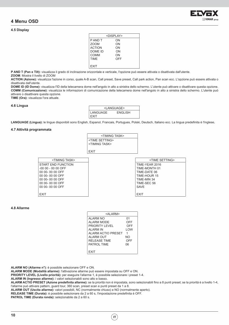
4.5 Display
4 Menu OSD
IT
<DISPLAY>P AND T ONZOOM ONACTION ONDOME ID ONCOMM ONTIME OFF
EXIT
P AND T (Pan e Tilt): visualizza il grado di inclinazione orizzontale e verticale, l'opzione può essere attivata o disattivata dall'utente. ZOOM: Mostra il livello di ZOOMACTION (Azione): visualizza l'azione in corso, quale A-B scan, Call preset, Save preset, Call park action, Pan scan ecc. L'opzione può essere attivata o disattivata dall'utente.DOME ID (ID Dome): visualizza l'ID della telecamera dome nell'angolo in alto a sinistra dello schermo. L'utente può attivare o disattivare questa opzione. COMM (Comunicazione): visualizza le informazioni di comunicazione della telecamera dome nell'angolo in alto a sinistra dello schermo. L'utente può attivare o disattivare questa opzione. TIME (Ora): visualizza l'ora attuale.
4.6 Lingua<LANGUAGE>
LANGUAGE ENGLISHEXIT
LANGUAGE (Lingua): le lingue disponibili sono English, Espanol, Francais, Portugues, Polski, Deutsch, Italiano ecc. La lingua predefinita è l'inglese.
4.7 Attività programmata
<TIMING TASK><TIME SETTING><TIMING TASK>
EXIT
<TIMING TASK>START END FUNCTION-00 00 - 00 00 OFF00 00- 00 00 OFF00 00- 00 00 OFF00 00- 00 00 OFF00 00- 00 00 OFF00 00- 00 00 OFF
EXIT
<TIME SETTING>TIME-YEAR 2016TIME-MONTH 01TIME-DATE 06TIME-HOUR 15TIME-MIN 34TIME-SEC 56SAVE
EXIT
4.8 Allarme<ALARM>
ALARM NO 01ALARM MODE OFFPRIORITY LEVEL OFFALARM IN LOWALARM ACTIO PRESET 1ALARM OUT NORELEASE TIME OFFPATROL TIME 06
EXIT
ALARM NO (Allarme n°): è possibile selezionare OFF e ON.ALARM MODE (Modalità allarme): l'attivazione allarme può essere impostata su OFF e ON.PRIORITY LEVEL (Livello priorità): per eseguire l'allarme 1, è possibile selezionare i preset 1-4.ALARM IN (Ingresso allarme): i valori selezionabili sono alto e basso.ALARM ACTIO PRESET (Azione predefinita allarme): se la priorità non è impostata, sono selezionabili fino a 8 punti preset; se la priorità è a livello 1-4, l'allarme può attivare pattern, guard tour, 360 scan, preset scan e punti preset da 1 a 8.ALARM OUT (Uscita allarme): valori possibili, NC (normalmente chiuso) e NO (normalmente aperto).RELEASE TIME (Durata): è possibile selezionare da 2 a 60 s, l'impostazione predefinita è OFF.PATROL TIME (Durata ronda): selezionabile da 2 a 60 s.
11VIMAR group
4 Menu OSD
IT
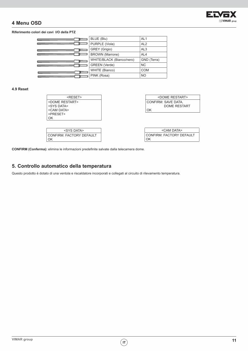
BLUE (Blu) AL1PURPLE (Viola) AL2GREY (Grigio) AL3BROWN (Marrone) AL4WHITE/BLACK (Bianco/nero) GND (Terra)GREEN (Verde) NCWHITE (Bianco) COMPINK (Rosa) NO
4.9 Reset
<RESET><DOME RESTART><SYS DATA><CAM DATA><PRESET>OK
<DOME RESTART>CONFIRM: SAVE DATA, DOME RESTARTOK
<SYS DATA>CONFIRM: FACTORY DEFAULT OK
<CAM DATA>CONFIRM: FACTORY DEFAULT OK
CONFIRM (Conferma): elimina le informazioni predefinite salvate dalla telecamera dome.
5. Controllo automatico della temperaturaQuesto prodotto è dotato di una ventola e riscaldatore incorporati e collegati al circuito di rilevamento temperatura.
Riferimento colori dei cavi I/O della PTZ
12
Appendice
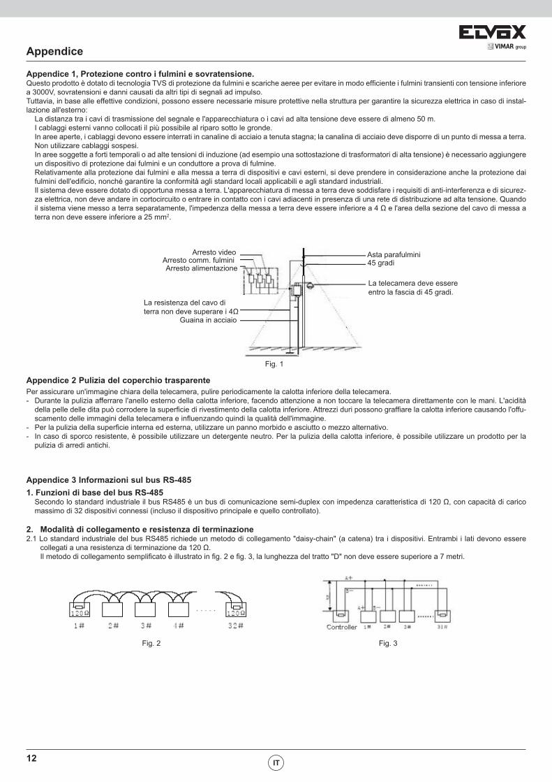
Appendice 1, Protezione contro i fulmini e sovratensione. Questo prodotto è dotato di tecnologia TVS di protezione da fulmini e scariche aeree per evitare in modo efficiente i fulmini transienti con tensione inferiore a 3000V, sovratensioni e danni causati da altri tipi di segnali ad impulso.Tuttavia, in base alle effettive condizioni, possono essere necessarie misure protettive nella struttura per garantire la sicurezza elettrica in caso di instal-lazione all'esterno: La distanza tra i cavi di trasmissione del segnale e l'apparecchiatura o i cavi ad alta tensione deve essere di almeno 50 m. I cablaggi esterni vanno collocati il più possibile al riparo sotto le gronde. In aree aperte, i cablaggi devono essere interrati in canaline di acciaio a tenuta stagna; la canalina di acciaio deve disporre di un punto di messa a terra.
Non utilizzare cablaggi sospesi. In aree soggette a forti temporali o ad alte tensioni di induzione (ad esempio una sottostazione di trasformatori di alta tensione) è necessario aggiungere
un dispositivo di protezione dai fulmini e un conduttore a prova di fulmine. Relativamente alla protezione dai fulmini e alla messa a terra di dispositivi e cavi esterni, si deve prendere in considerazione anche la protezione dai
fulmini dell'edificio, nonché garantire la conformità agli standard locali applicabili e agli standard industriali. Il sistema deve essere dotato di opportuna messa a terra. L'apparecchiatura di messa a terra deve soddisfare i requisiti di anti-interferenza e di sicurez-
za elettrica, non deve andare in cortocircuito o entrare in contatto con i cavi adiacenti in presenza di una rete di distribuzione ad alta tensione. Quando il sistema viene messo a terra separatamente, l'impedenza della messa a terra deve essere inferiore a 4 Ω e l'area della sezione del cavo di messa a terra non deve essere inferiore a 25 mm2.
Appendice 2 Pulizia del coperchio trasparentePer assicurare un'immagine chiara della telecamera, pulire periodicamente la calotta inferiore della telecamera.- Durante la pulizia afferrare l'anello esterno della calotta inferiore, facendo attenzione a non toccare la telecamera direttamente con le mani. L'acidità
della pelle delle dita può corrodere la superficie di rivestimento della calotta inferiore. Attrezzi duri possono graffiare la calotta inferiore causando l'offu-scamento delle immagini della telecamera e influenzando quindi la qualità dell'immagine.
- Per la pulizia della superficie interna ed esterna, utilizzare un panno morbido e asciutto o mezzo alternativo.- In caso di sporco resistente, è possibile utilizzare un detergente neutro. Per la pulizia della calotta inferiore, è possibile utilizzare un prodotto per la
pulizia di arredi antichi.
Appendice 3 Informazioni sul bus RS-485 1. Funzioni di base del bus RS-485 Secondo lo standard industriale il bus RS485 è un bus di comunicazione semi-duplex con impedenza caratteristica di 120 Ω, con capacità di carico
massimo di 32 dispositivi connessi (incluso il dispositivo principale e quello controllato).
2. Modalità di collegamento e resistenza di terminazione2.1 Lo standard industriale del bus RS485 richiede un metodo di collegamento "daisy-chain" (a catena) tra i dispositivi. Entrambi i lati devono essere
collegati a una resistenza di terminazione da 120 Ω. Il metodo di collegamento semplificato è illustrato in fig. 2 e fig. 3, la lunghezza del tratto "D" non deve essere superiore a 7 metri.
Arresto videoArresto comm. fulminiArresto alimentazione
La resistenza del cavo di terra non deve superare i 4Ω
Guaina in acciaio
Asta parafulmini45 gradi
La telecamera deve essere entro la fascia di 45 gradi.
Fig. 1
Fig. 2 Fig. 3
IT
13VIMAR groupEN
WARNINGTO REDUCE THE RISK OF FIRE OR ELECTRIC SHOCK, DO NOT EXPOSE THIS PRODUCT TO RAIN OR MOISTURE. DO NOT INSERT ANY METAL-LIC OBJECTS THROUGH VENTILATION GRILLS OR OPENINGS ON THE EQUIPMENT.
CAUTION
Warnings and cautions
EXPLANATION OF GRAPHICAL SYMBOLSThe lighting flash with arrowhead symbol, within an equilateral triangle, is intended to alert the user the presence of non-insulated “dangerous volt-age” within the product’s enclosure that maybe of sufficient magnitude to constitute a risk of electric shock to different persons.
The exclamation point within an equilateral triangle, is intended to alert the user the presence of important operating and maintenance (servicing) instructions in the literature accompanying this product
PRECAUTIONS:1. Persons without technical qualifications should not attempt to operate this dome device before reading this manual thoroughly. 2. Remove any power to the dome before attempting any operations or adjustments inside the dome cover to avoid potential damage to the mechanism.3. Inside the dome cover there are precision optical and electrical devices. Heavy pressure, shock and other sudden adjustments or operations should
be avoided. Otherwise, you may cause irreparable damage to the product.4. Please DO NOT remove or disassemble any internal parts of the video camera to avoid normal operation and possibly void the warranty. There are
no serviceable parts inside the camera.5. All electrical connections to the dome should be made in strict accordance with the attached labels and wiring instructions in this manual. Failure to do
so may damage the dome beyond repair and void the warranty.6. For outdoor installation especially in high places or poles, it is highly recommended that the proper lightning arrestors and surge suppressors are
installed before the dome is entered into service.7. Please do not use the product under circumstances where the limits exceed the maximum specified temperature, humidity or power supply specifica-
tions.
IMPORTANT SAFEGUARDS1. Read these instructions before attempting installation or operation of dome device2. Keep these instructions for future reference3. Heed all warnings and adhere to electrical specifications Follow all instructions4. Clean only with non abrasive dry cotton cloth, lint free and approved acrylic cleaners5. Should the lens of the camera become dirty, use special lens cleaning cloth and solution to properly clean it.6. Do not block any ventilation openings. Install in accordance with manufacturer’s instructions7. Use only attachments or accessories specified by the manufacturer8. Verify that the surface you are planning to use for attaching the dome can adequately support the weight of the device and mounting hardware9. Protect this devices against lighting storms with proper power supplies10. Refer all servicing to qualified service personnel. Servicing is required when the device has been damaged in any way, when liquid traces are present,
or the presence of loose objects is evident or if the device does not function properly, or has received sever impact or has been dropped accidentally.11. Indoor dome is for indoor use only and not suitable for outdoor or high humidity locations. Do not use this product under circumstances exceeding
specified temperature and humidity ratings.12. Avoid pointing the camera directly to the sun or other extremely bright objects for prolonged period of time avoiding the risk of permanent damages
to the imaging sensor.13. The attached instructions are for use by qualified personnel only. To reduce the risks of electric shock do not perform any servicing other than contained
in the operating instructions unless you are qualified to do so.14. During usage, user should abide by all electrical safety standards and adhere to electrical specifications for the operation of the dome. The control
cable for RS485 communications as well as the video signal cables should be isolated from high voltage equipment and or high voltage cables.15. Use supplied power supply transformer only.
14 EN
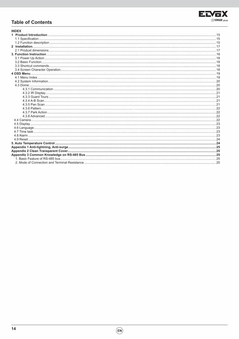
Table of ContentsINDEX1 Product Introduction ............................................................................................................................................................................................15 1.1 Specification ......................................................................................................................................................................................................15 1.2 Function description ..........................................................................................................................................................................................152 Installation..................................................................................................................... ........................................................................................17 2.1 Produxt dimensions ...........................................................................................................................................................................................173. Function Instruction ..............................................................................................................................................................................................18 3.1 Power Up Action ................................................................................................................................................................................................18 3.2 Basic Function ...................................................................................................................................................................................................18 3.3 Shortcut commends...........................................................................................................................................................................................18 3.4 Screen Character Operation..............................................................................................................................................................................184 OSD Menu ...............................................................................................................................................................................................................19 4.1 Menu Index ........................................................................................................................................................................................................19 4.2 System Information............................................................................................................................................................................................20 4.3 Dome .................................................................................................................................................................................................................20 4.3.1 Communication ......................................................................................................................................................................................20 4.3.2 IR Display...............................................................................................................................................................................................21 4.3.3 Guard Tours ...........................................................................................................................................................................................21 4.3.4 A-B Scan ................................................................................................................................................................................................21 4.3.5 Pan Scan ...............................................................................................................................................................................................21 4.3.6 Pattern....................................................................................................... ............................................................................................22 4.3.7 Park Action .............................................................................................................................................................................................22 4.3.8 Advanced ...............................................................................................................................................................................................22 4.4 Camera ...............................................................................................................................................................................................................22 4.5 Display ................................................................................................................................................................................................................23 4.6 Language............................................................................................................................................................................................................23 4.7 Time task ............................................................................................................................................................................................................23 4.8 Alarm ..................................................................................................................................................................................................................23 4.9 Reset ..................................................................................................................................................................................................................245. Auto Temperature Control ....................................................................................................................................................................................24Appendix 1 Anti-lightning, Anti-surge .....................................................................................................................................................................25Appendix 2 Clean Transparent Cover......................................................................................................................................................................25Appendix 3 Common Knowledge on RS-485 Bus ..................................................................................................................................................25 1. Basic Feature of RS-485 bus ..............................................................................................................................................................................25 2. Mode of Connection and Terminal Resistance ...................................................................................................................................................25
15VIMAR group
1 Product introduction
1.1 Specification
EN
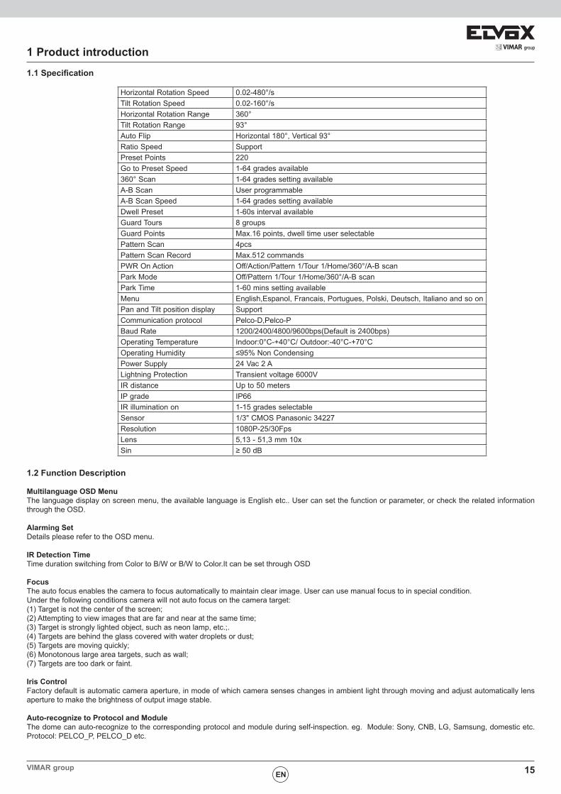
Horizontal Rotation Speed 0.02-480°/sTilt Rotation Speed 0.02-160°/sHorizontal Rotation Range 360°Tilt Rotation Range 93°Auto Flip Horizontal 180°, Vertical 93°Ratio Speed SupportPreset Points 220Go to Preset Speed 1-64 grades available360° Scan 1-64 grades setting availableA-B Scan User programmableA-B Scan Speed 1-64 grades setting availableDwell Preset 1-60s interval availableGuard Tours 8 groupsGuard Points Max.16 points, dwell time user selectablePattern Scan 4pcsPattern Scan Record Max.512 commandsPWR On Action Off/Action/Pattern 1/Tour 1/Home/360°/A-B scanPark Mode Off/Pattern 1/Tour 1/Home/360°/A-B scanPark Time 1-60 mins setting availableMenu English,Espanol, Francais, Portugues, Polski, Deutsch, Italiano and so onPan and Tilt position display SupportCommunication protocol Pelco-D,Pelco-PBaud Rate 1200/2400/4800/9600bps(Default is 2400bps)Operating Temperature Indoor:0°C-+40°C/ Outdoor:-40°C-+70°COperating Humidity ≤95% Non CondensingPower Supply 24 Vac 2 ALightning Protection Transient voltage 6000VIR distance Up to 50 metersIP grade IP66IR illumination on 1-15 grades selectableSensor 1/3" CMOS Panasonic 34227Resolution 1080P-25/30FpsLens 5,13 - 51,3 mm 10xSin ≥ 50 dB
1.2 Function Description
Multilanguage OSD MenuThe language display on screen menu, the available language is English etc.. User can set the function or parameter, or check the related information through the OSD.
Alarming SetDetails please refer to the OSD menu.
IR Detection TimeTime duration switching from Color to B/W or B/W to Color.It can be set through OSD
FocusThe auto focus enables the camera to focus automatically to maintain clear image. User can use manual focus to in special condition.Under the following conditions camera will not auto focus on the camera target:(1) Target is not the center of the screen;(2) Attempting to view images that are far and near at the same time;(3) Target is strongly lighted object, such as neon lamp, etc.;.(4) Targets are behind the glass covered with water droplets or dust;(5) Targets are moving quickly;(6) Monotonous large area targets, such as wall;(7) Targets are too dark or faint.
Iris ControlFactory default is automatic camera aperture, in mode of which camera senses changes in ambient light through moving and adjust automatically lens aperture to make the brightness of output image stable.
Auto-recognize to Protocol and ModuleThe dome can auto-recognize to the corresponding protocol and module during self-inspection. eg. Module: Sony, CNB, LG, Samsung, domestic etc. Protocol: PELCO_P, PELCO_D etc.
16
1 Product introductionDay/Night SwitchWith auto day/night switch function, when the illumination is low the picture will auto switch from day to night mode and when the illumination is high enough the picture will auto switch from night to day mode
Ratio SpeedIntelligent pan and tilt speed is variable depend on the zoom factor. When zooming in, the speed will become slower and when zooming out, the speed will become quicker.
A-B ScanDome circularly scan close-up real-time scene according to A-B points at setting speed in both horizontal and vertical directions.
Pan ScanDome 360°clockwise continuous scan the display scene at setting speed in horizontal direction under the condition that pitch angle remains the same.
PresetAfter the dome camera keeps arbitrary PTZ location, it will automatically move to the defined position when preset is called.
Guard Tour ScanDome patrol scans according to certain edited preset order.
Power Off MemoryThis feature allows the dome to resume its previous preset or status after power is restored. By default setting, the dome support power up memory, which improves the reliability and avoids repeated settings of the parameter.
Park ActionIf users don’t operate the dome in set time, it will automatically run preset specific mode (pan scan, A-B scan, park action, cruise, preserve action etc.).
Zero AlignmentThere is a point specified as zero point. When the dome is working, the preset point is not accurate because of something caused by the operator. User can make the dome automatically enable the zero alignment by operational order.
Auto FlipIn the manual tracking mode, when a target goes directly beneath the dome, the dome will automatically rotate 180 degree in horizontal direction to main-tain continuity tracking. When the dome flips, the camera starts moving upward as long as you hold the joystick in the down position.
EN

17VIMAR group
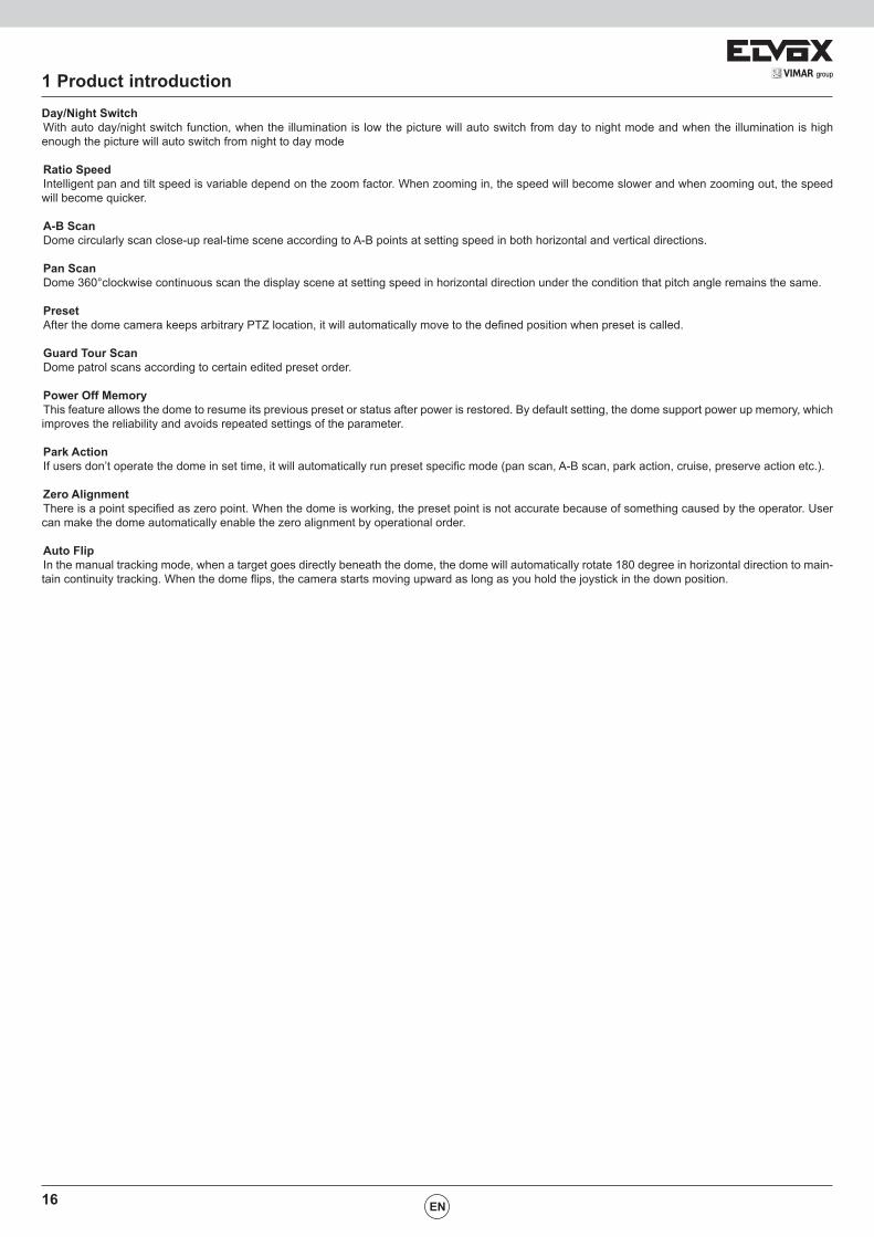
2.1 Product Dimension
2 Installation
EN
18
3 Function Instruction
EN
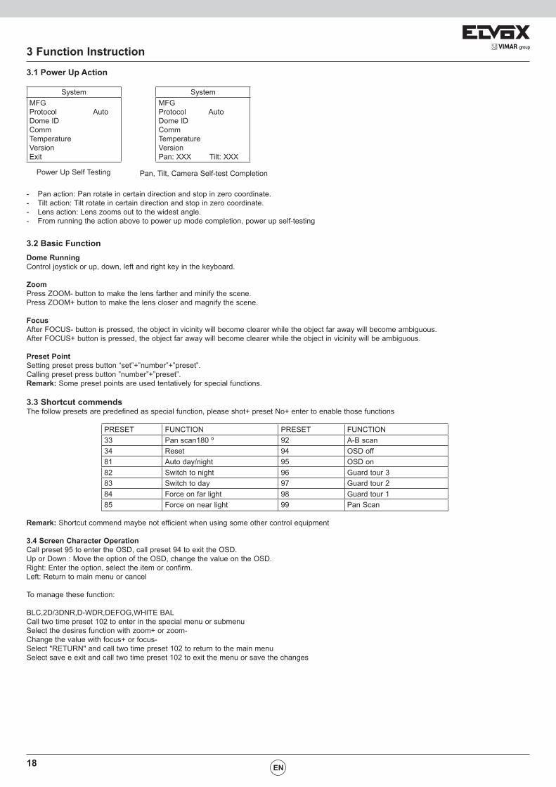
3.1 Power Up Action
SystemMFGProtocol AutoDome IDCommTemperatureVersionExit
SystemMFGProtocol AutoDome IDCommTemperatureVersionPan: XXX Tilt: XXX
Power Up Self Testing Pan, Tilt, Camera Self-test Completion
- Pan action: Pan rotate in certain direction and stop in zero coordinate.- Tilt action: Tilt rotate in certain direction and stop in zero coordinate.- Lens action: Lens zooms out to the widest angle.- From running the action above to power up mode completion, power up self-testing
3.2 Basic FunctionDome RunningControl joystick or up, down, left and right key in the keyboard.
ZoomPress ZOOM- button to make the lens farther and minify the scene.Press ZOOM+ button to make the lens closer and magnify the scene.
FocusAfter FOCUS- button is pressed, the object in vicinity will become clearer while the object far away will become ambiguous. After FOCUS+ button is pressed, the object far away will become clearer while the object in vicinity will be ambiguous.
Preset PointSetting preset press button “set”+”number”+”preset”.Calling preset press button ”number”+”preset”.Remark: Some preset points are used tentatively for special functions.
3.3 Shortcut commendsThe follow presets are predefined as special function, please shot+ preset No+ enter to enable those functions
PRESET FUNCTION PRESET FUNCTION33 Pan scan180 º 92 A-B scan34 Reset 94 OSD off81 Auto day/night 95 OSD on82 Switch to night 96 Guard tour 383 Switch to day 97 Guard tour 284 Force on far light 98 Guard tour 185 Force on near light 99 Pan Scan
Remark: Shortcut commend maybe not efficient when using some other control equipment
3.4 Screen Character OperationCall preset 95 to enter the OSD, call preset 94 to exit the OSD. Up or Down : Move the option of the OSD, change the value on the OSD.Right: Enter the option, select the item or confirm.Left: Return to main menu or cancel
To manage these function:
BLC,2D/3DNR,D-WDR,DEFOG,WHITE BALCall two time preset 102 to enter in the special menu or submenuSelect the desires function with zoom+ or zoom-Change the value with focus+ or focus-Select "RETURN" and call two time preset 102 to return to the main menuSelect save e exit and call two time preset 102 to exit the menu or save the changes
19VIMAR group
4 OSD Menu
EN
4.1 Menu Index
20
4 OSD Menu
EN
4.2 System Information
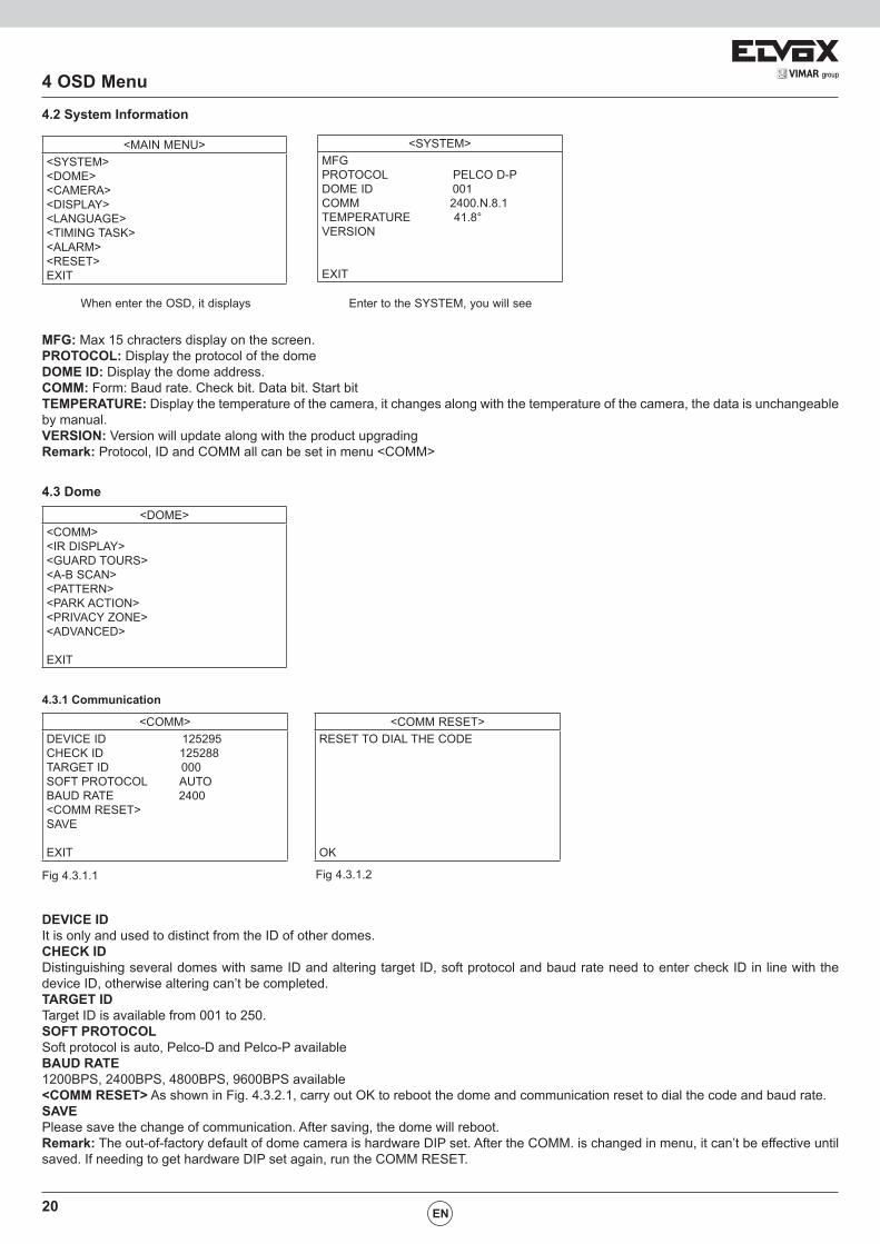
<MAIN MENU><SYSTEM><DOME><CAMERA><DISPLAY><LANGUAGE><TIMING TASK><ALARM><RESET> EXIT
<SYSTEM>MFGPROTOCOL PELCO D-PDOME ID 001COMM 2400.N.8.1TEMPERATURE 41.8°VERSION
EXIT
When enter the OSD, it displays Enter to the SYSTEM, you will see
MFG: Max 15 chracters display on the screen.PROTOCOL: Display the protocol of the domeDOME ID: Display the dome address.COMM: Form: Baud rate. Check bit. Data bit. Start bitTEMPERATURE: Display the temperature of the camera, it changes along with the temperature of the camera, the data is unchangeable by manual.VERSION: Version will update along with the product upgradingRemark: Protocol, ID and COMM all can be set in menu <COMM>
4.3 Dome<DOME>
<COMM><IR DISPLAY><GUARD TOURS><A-B SCAN><PATTERN><PARK ACTION><PRIVACY ZONE><ADVANCED>
EXIT
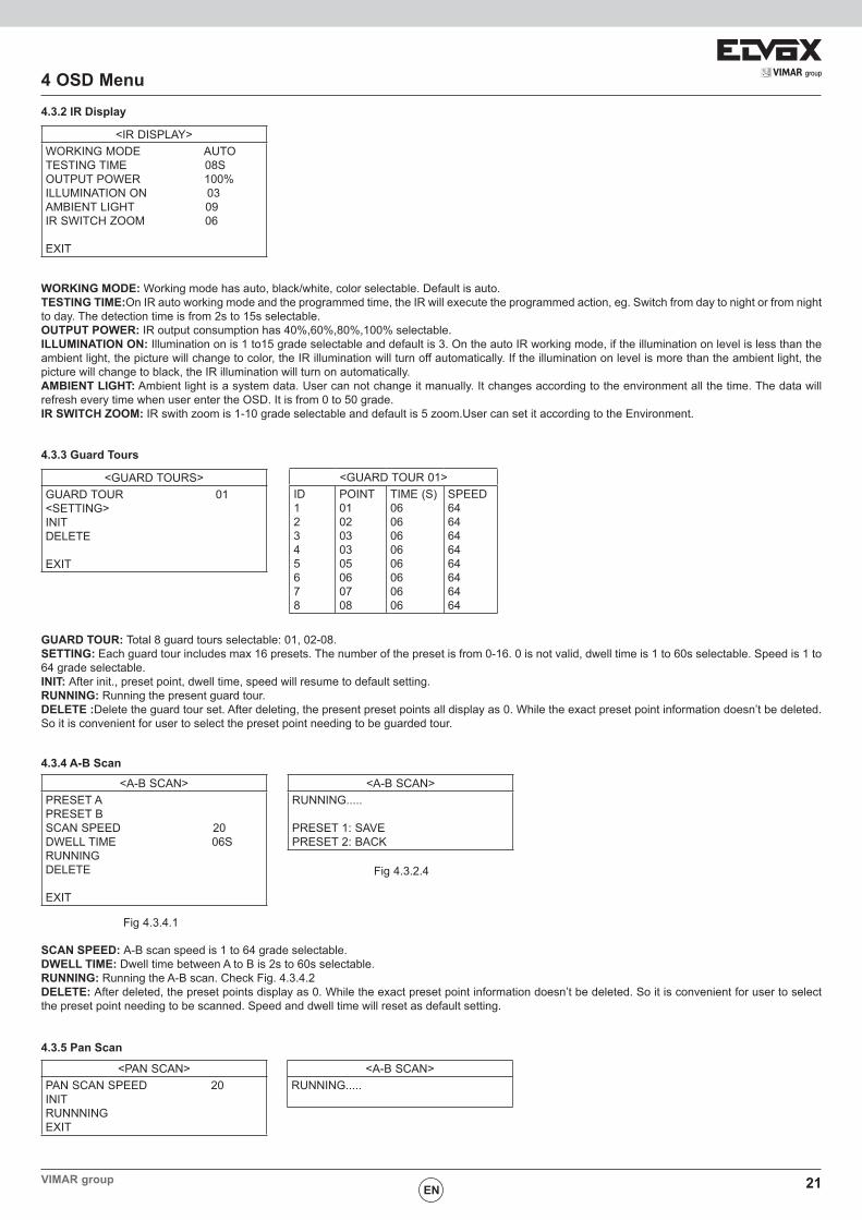
4.3.1 Communication
<COMM>DEVICE ID 125295CHECK ID 125288TARGET ID 000SOFT PROTOCOL AUTOBAUD RATE 2400<COMM RESET>SAVE
EXIT
<COMM RESET>RESET TO DIAL THE CODE
OK
Fig 4.3.1.1 Fig 4.3.1.2
DEVICE IDIt is only and used to distinct from the ID of other domes.CHECK IDDistinguishing several domes with same ID and altering target ID, soft protocol and baud rate need to enter check ID in line with the device ID, otherwise altering can’t be completed.TARGET IDTarget ID is available from 001 to 250.SOFT PROTOCOLSoft protocol is auto, Pelco-D and Pelco-P availableBAUD RATE1200BPS, 2400BPS, 4800BPS, 9600BPS available<COMM RESET> As shown in Fig. 4.3.2.1, carry out OK to reboot the dome and communication reset to dial the code and baud rate.SAVEPlease save the change of communication. After saving, the dome will reboot.Remark: The out-of-factory default of dome camera is hardware DIP set. After the COMM. is changed in menu, it can’t be effective until saved. If needing to get hardware DIP set again, run the COMM RESET.
21VIMAR group
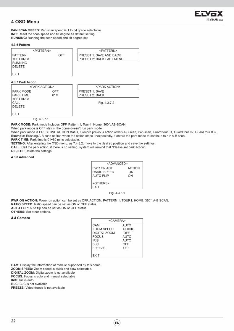
4 OSD Menu4.3.2 IR Display
EN
<IR DISPLAY>WORKING MODE AUTOTESTING TIME 08SOUTPUT POWER 100%ILLUMINATION ON 03AMBIENT LIGHT 09IR SWITCH ZOOM 06
EXIT
WORKING MODE: Working mode has auto, black/white, color selectable. Default is auto.TESTING TIME:On IR auto working mode and the programmed time, the IR will execute the programmed action, eg. Switch from day to night or from night to day. The detection time is from 2s to 15s selectable. OUTPUT POWER: IR output consumption has 40%,60%,80%,100% selectable.ILLUMINATION ON: Illumination on is 1 to15 grade selectable and default is 3. On the auto IR working mode, if the illumination on level is less than the ambient light, the picture will change to color, the IR illumination will turn off automatically. If the illumination on level is more than the ambient light, the picture will change to black, the IR illumination will turn on automatically. AMBIENT LIGHT: Ambient light is a system data. User can not change it manually. It changes according to the environment all the time. The data will refresh every time when user enter the OSD. It is from 0 to 50 grade. IR SWITCH ZOOM: IR swith zoom is 1-10 grade selectable and default is 5 zoom.User can set it according to the Environment.
4.3.3 Guard Tours
<GUARD TOURS>GUARD TOUR 01<SETTING>INITDELETE
EXIT
<GUARD TOUR 01>ID12345678
POINT 01 02 03 03 05 060708
TIME (S) 06 06 06 06 06 06 06 06
SPEED 6464646464646464
GUARD TOUR: Total 8 guard tours selectable: 01, 02-08.SETTING: Each guard tour includes max 16 presets. The number of the preset is from 0-16. 0 is not valid, dwell time is 1 to 60s selectable. Speed is 1 to 64 grade selectable. INIT: After init., preset point, dwell time, speed will resume to default setting.RUNNING: Running the present guard tour.DELETE :Delete the guard tour set. After deleting, the present preset points all display as 0. While the exact preset point information doesn’t be deleted. So it is convenient for user to select the preset point needing to be guarded tour.
4.3.4 A-B Scan
<A-B SCAN>PRESET APRESET B SCAN SPEED 20DWELL TIME 06SRUNNINGDELETE
EXIT
<A-B SCAN>RUNNING..... PRESET 1: SAVEPRESET 2: BACK
Fig 4.3.4.1
Fig 4.3.2.4
SCAN SPEED: A-B scan speed is 1 to 64 grade selectable.DWELL TIME: Dwell time between A to B is 2s to 60s selectable. RUNNING: Running the A-B scan. Check Fig. 4.3.4.2DELETE: After deleted, the preset points display as 0. While the exact preset point information doesn’t be deleted. So it is convenient for user to select the preset point needing to be scanned. Speed and dwell time will reset as default setting.
4.3.5 Pan Scan
<PAN SCAN>PAN SCAN SPEED 20INITRUNNNINGEXIT
<A-B SCAN>RUNNING.....
22
4 OSD Menu
EN
PAN SCAN SPEED: Pan scan speed is 1 to 64 grade selectable.INIT: Reset the scan speed and tilt degree as default setting.RUNNING: Running the scan speed and tilt degree set
4.3.6 Pattern
<PATTERN>PATTERN OFF<SETTING>RUNNINGDELETE
EXIT
<PATTERN>PRESET 1: SAVE AND BACKPRESET 2: BACK LAST MENU
4.3.7 Park Action
Fig. 4.3.7.1
Fig. 4.3.7.2
PARK MODE: Park mode includes OFF, Pattern 1, Tour 1, Home, 360°, AB-SCAN.When park mode is OFF status, the dome doesn’t run park mode.When park mode is PRESERVE ACTION status, it record previous action order (A-B scan, Pan scan, Guard tour 01, Guard tour 02, Guard tour 03).Example: Running A-B scan at first, when the action stops unexpectedly, it enters the park mode to continue to run A-B scan.PARK TIME: Park time is 01~60 mins selectable.SETTING: After entering the OSD menu, as 7.4.8.2, move to the desired position and save the settings. CALL: Call the park action, if there is no setting, system will remind that “Please set park action”.DELETE: Delete the settings.
4.3.8 Advanced
<ADVANCED>PWR ON ACT ACTIONRADIO SPEED ONAUTO FLIP ON
<OTHERS>EXIT
Fig. 4.3.8.1
PWR ON ACTION: Power on action can be set as OFF, ACTION, PATTERN 1, TOUR1, HOME, 360°, A-B SCAN.RATIO SPEED: Ratio speed can be set as ON or OFF statusAUTO FLIP: Auto flip can be set as ON or OFF status.OTHERS: Set other options.
4.4 Camera<CAMERA>
CAM AUTOZOOM SPEED QUICKDIGITAL ZOOM OFFFOCUS AUTOIRIS AUTOBLC OFFFREEZE OFF
EXIT
CAM: Display the information of module supported by this dome.ZOOM SPEED: Zoom speed is quick and slow selectable.DIGITAL ZOOM: Digital zoom is not availableFOCUS: Focus is auto and manual selectableIRIS: Iris is autoBLC: BLC is not available FREEZE: Video freeze is not available
<PARK ACTION>PARK MODE OFFPARK TIME 01M<SETTING>CALLDELETE
EXIT
<PARK ACTION>PRESET 1: SAVEPRESET 2: BACK
23VIMAR group
4.5 Display
4 OSD Menu
EN
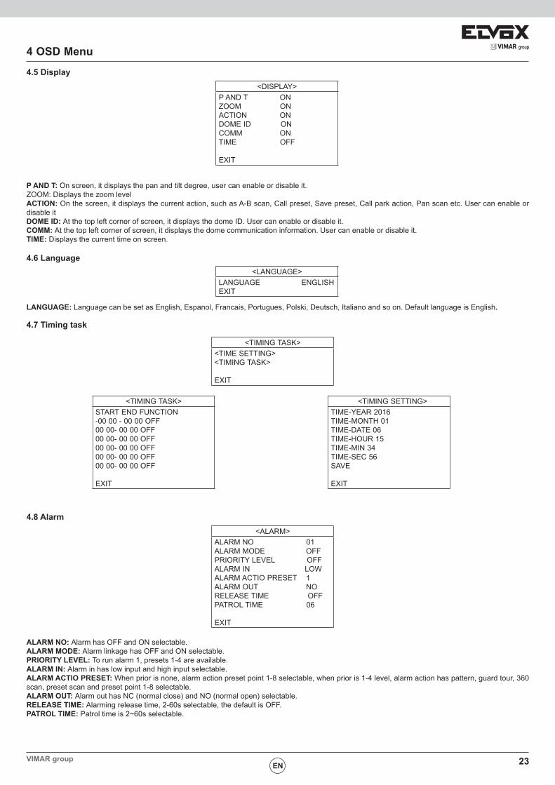
P AND T: On screen, it displays the pan and tilt degree, user can enable or disable it. ZOOM: Displays the zoom levelACTION: On the screen, it displays the current action, such as A-B scan, Call preset, Save preset, Call park action, Pan scan etc. User can enable or disable itDOME ID: At the top left corner of screen, it displays the dome ID. User can enable or disable it. COMM: At the top left corner of screen, it displays the dome communication information. User can enable or disable it. TIME: Displays the current time on screen.
4.6 Language<LANGUAGE>
LANGUAGE ENGLISHEXIT
LANGUAGE: Language can be set as English, Espanol, Francais, Portugues, Polski, Deutsch, Italiano and so on. Default language is English.
4.7 Timing task
<TIMING TASK><TIME SETTING><TIMING TASK>
EXIT
<TIMING TASK>START END FUNCTION-00 00 - 00 00 OFF00 00- 00 00 OFF00 00- 00 00 OFF00 00- 00 00 OFF00 00- 00 00 OFF00 00- 00 00 OFF
EXIT
<TIMING SETTING>TIME-YEAR 2016TIME-MONTH 01TIME-DATE 06TIME-HOUR 15TIME-MIN 34TIME-SEC 56SAVE
EXIT
4.8 Alarm<ALARM>
ALARM NO 01ALARM MODE OFFPRIORITY LEVEL OFFALARM IN LOWALARM ACTIO PRESET 1ALARM OUT NORELEASE TIME OFFPATROL TIME 06
EXIT
ALARM NO: Alarm has OFF and ON selectable.ALARM MODE: Alarm linkage has OFF and ON selectable.PRIORITY LEVEL: To run alarm 1, presets 1-4 are available.ALARM IN: Alarm in has low input and high input selectable.ALARM ACTIO PRESET: When prior is none, alarm action preset point 1-8 selectable, when prior is 1-4 level, alarm action has pattern, guard tour, 360 scan, preset scan and preset point 1-8 selectable.ALARM OUT: Alarm out has NC (normal close) and NO (normal open) selectable.RELEASE TIME: Alarming release time, 2-60s selectable, the default is OFF.PATROL TIME: Patrol time is 2~60s selectable.
<DISPLAY>P AND T ONZOOM ONACTION ONDOME ID ONCOMM ONTIME OFF
EXIT
24
4 OSD Menu
EN
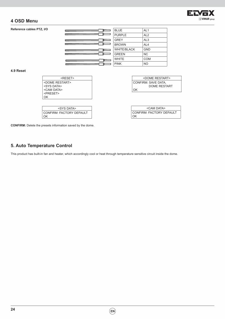
BLUE AL1PURPLE AL2GREY AL3BROWN AL4WHITE/BLACK GNDGREEN NCWHITE COMPINK NO
4.9 Reset
<RESET><DOME RESTART><SYS DATA><CAM DATA><PRESET>OK
<DOME RESTART>CONFIRM: SAVE DATA, DOME RESTARTOK
<SYS DATA>CONFIRM: FACTORY DEFAULT OK
<CAM DATA>CONFIRM: FACTORY DEFAULT OK
CONFIRM: Delete the presets information saved by the dome.
5. Auto Temperature ControlThis product has built-in fan and heater, which accordingly cool or heat through temperature sensitive circuit inside the dome.
Reference cables PTZ, I/O
25VIMAR group
Appendix
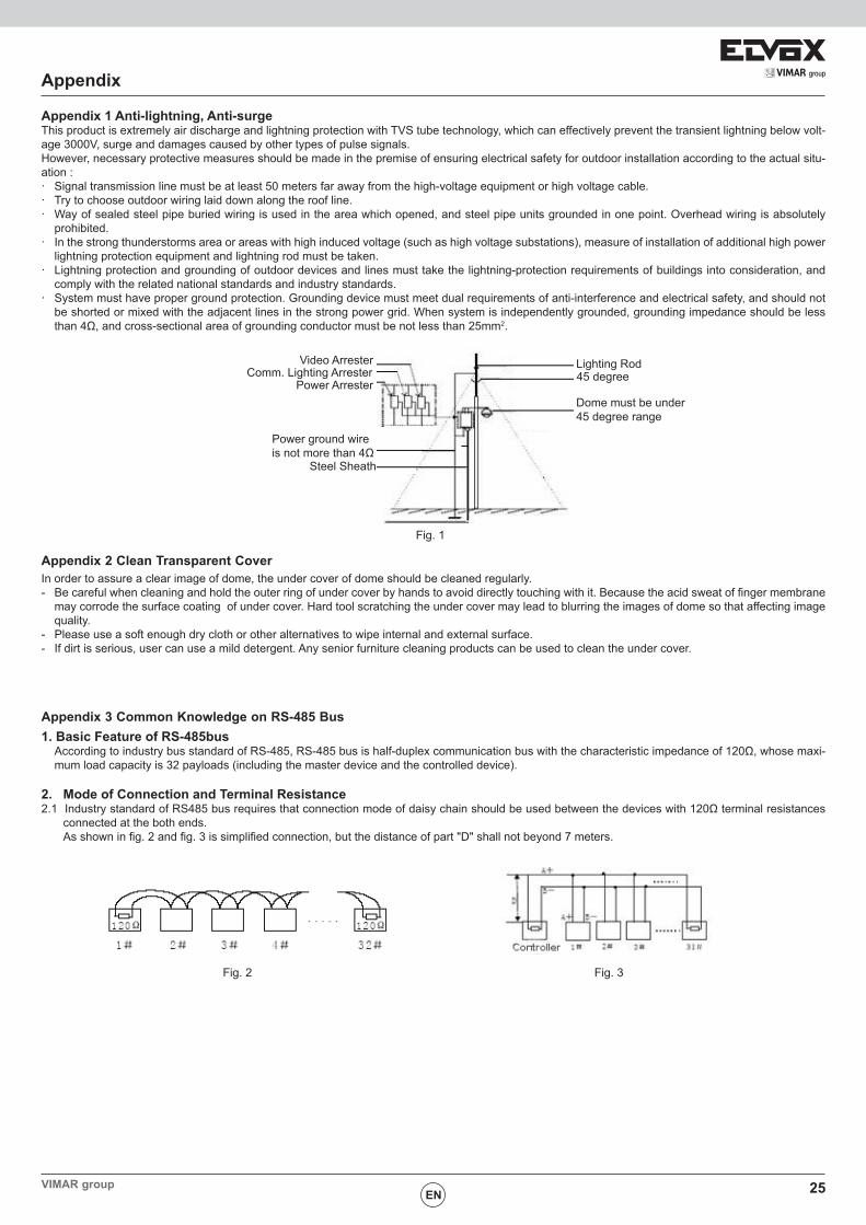
Appendix 1 Anti-lightning, Anti-surge This product is extremely air discharge and lightning protection with TVS tube technology, which can effectively prevent the transient lightning below volt-age 3000V, surge and damages caused by other types of pulse signals.However, necessary protective measures should be made in the premise of ensuring electrical safety for outdoor installation according to the actual situ-ation :· Signal transmission line must be at least 50 meters far away from the high-voltage equipment or high voltage cable.· Try to choose outdoor wiring laid down along the roof line.· Way of sealed steel pipe buried wiring is used in the area which opened, and steel pipe units grounded in one point. Overhead wiring is absolutely
prohibited.· In the strong thunderstorms area or areas with high induced voltage (such as high voltage substations), measure of installation of additional high power
lightning protection equipment and lightning rod must be taken.· Lightning protection and grounding of outdoor devices and lines must take the lightning-protection requirements of buildings into consideration, and
comply with the related national standards and industry standards.· System must have proper ground protection. Grounding device must meet dual requirements of anti-interference and electrical safety, and should not
be shorted or mixed with the adjacent lines in the strong power grid. When system is independently grounded, grounding impedance should be less than 4Ω, and cross-sectional area of grounding conductor must be not less than 25mm2.
EN
Appendix 2 Clean Transparent CoverIn order to assure a clear image of dome, the under cover of dome should be cleaned regularly.- Be careful when cleaning and hold the outer ring of under cover by hands to avoid directly touching with it. Because the acid sweat of finger membrane
may corrode the surface coating of under cover. Hard tool scratching the under cover may lead to blurring the images of dome so that affecting image quality.
- Please use a soft enough dry cloth or other alternatives to wipe internal and external surface.- If dirt is serious, user can use a mild detergent. Any senior furniture cleaning products can be used to clean the under cover.
Appendix 3 Common Knowledge on RS-485 Bus 1. Basic Feature of RS-485bus According to industry bus standard of RS-485, RS-485 bus is half-duplex communication bus with the characteristic impedance of 120Ω, whose maxi-
mum load capacity is 32 payloads (including the master device and the controlled device).
2. Mode of Connection and Terminal Resistance2.1 Industry standard of RS485 bus requires that connection mode of daisy chain should be used between the devices with 120Ω terminal resistances
connected at the both ends. As shown in fig. 2 and fig. 3 is simplified connection, but the distance of part "D" shall not beyond 7 meters.
Video ArresterComm. Lighting Arrester
Power Arrester
Power ground wire is not more than 4Ω
Steel Sheath
Lighting Rod45 degree
Dome must be under 45 degree range
Fig. 1
Fig. 2 Fig. 3

Viale Vicenza, 1436063 Marostica VI - Italy
www.vimar.com49401017A0 01 1701