DP - amet · DP. CILINDRI IDRAULICI ISO 6022. ISO 6022 HYDRAULIC CYLINDERS . CARATTERISTICHE...
8
2015 - Copyright © Conforti Oleodinamica Aggiornamenti su / updates on www.confortinet.com 30 2 DP CILINDRI IDRAULICI ISO 6022 ISO 6022 HYDRAULIC CYLINDERS CARATTERISTICHE TECNICHE TECHNICAL CHARACTERISTICS Cilindri idraulici per impieghi gravosi, conformi alla normativa ISO 6022. I cilindri sono disponibili in vari ancoraggi e in molteplici configurazioni di guarnizioni, in base alle condizioni di utilizzo e alle prestazioni desiderate. L’utilizzo di guide in bronzo per lo stelo e il pistone garantisce elevate prestazioni e durata nel tempo. Tutti i cilindri sono testati prima della consegna in conformità alla normativa ISO 10100. Hydraulic cylinders for heavy duty applications, in compliance with the ISO 6022 standard. The cylinders are available in many mountings and with several sealing configurations. The use of bronze guides for the rod and the piston guarantees high performances and a long life. All the cylinders are tested in compliance with the ISO 10100 standard. Cilindri a norma Standard cylinders Alesaggi mm Bore Pressione bar Pressure Corsa massima mm Max stroke Tolleranza sulla corsa Stroke tolerance Fluido Fluid Viscosità Viscosity ISO 6022 - DIN 24333 Alesaggi da 50 a 320 Bore from 50 to 320 nominale 250 operating 6000 0 + 2 mm Norma ISO 8131 ISO 8131 Standard Olio idraulico minerale Hydraulic mineral oil Esteri fosforici Phosphoric esters Acqua glicole HFC-fluid 12... 90 mm 2 /S massima 320 max CARATTERISTICHE TECNICHE SPECIFICATIONS 0,5 m/s 1 m/s 1 m/s 0,5 m/s - 20 - 20 - 20 - 20 + 80 + 80 + 150 + 80 Codice guarnizione Seal code Alta tenuta High sealing Olio idraulico Hydraulic oil Esteri fosforici Phosphoric esters Acqua glicole HFC-fluid Basso attrito Low friction Velocità max Max speed Temp °C Min Max Prestazioni Performance Fluido Fluid S L H G √ √ √ √ √ √ √ √ √ www.amet.com.pl
Transcript of DP - amet · DP. CILINDRI IDRAULICI ISO 6022. ISO 6022 HYDRAULIC CYLINDERS . CARATTERISTICHE...
2015 - Copyright © Conforti OleodinamicaAggiornamenti su / updates on www.confortinet.com 30
2
DP
CILINDRI IDRAULICI ISO 6022ISO 6022 HYDRAULIC CYLINDERS
CARATTERISTICHE TECNICHETECHNICAL CHARACTERISTICS
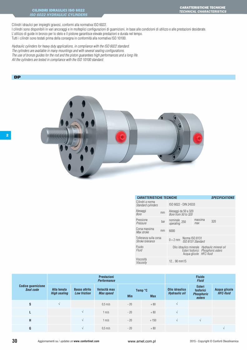
Cilindri idraulici per impieghi gravosi, conformi alla normativa ISO 6022. I cilindri sono disponibili in vari ancoraggi e in molteplici configurazioni di guarnizioni, in base alle condizioni di utilizzo e alle prestazioni desiderate.L’utilizzo di guide in bronzo per lo stelo e il pistone garantisce elevate prestazioni e durata nel tempo.Tutti i cilindri sono testati prima della consegna in conformità alla normativa ISO 10100.
Hydraulic cylinders for heavy duty applications, in compliance with the ISO 6022 standard. The cylinders are available in many mountings and with several sealing configurations.The use of bronze guides for the rod and the piston guarantees high performances and a long life.All the cylinders are tested in compliance with the ISO 10100 standard.
Cilindri a norma Standard cylinders
Alesaggi mmBore
Pressione bar Pressure
Corsa massima mm Max stroke
Tolleranza sulla corsa Stroke tolerance
Fluido Fluid
Viscosità Viscosity
ISO 6022 - DIN 24333
Alesaggi da 50 a 320 Bore from 50 to 320
nominale 250operating
6000
0 + 2 mm Norma ISO 8131 ISO 8131 Standard
Olio idraulico minerale Hydraulic mineral oil Esteri fosforici Phosphoric esters Acqua glicole HFC-fluid
12... 90 mm2/S
massima 320max
CARATTERISTICHE TECNICHE SPECIFICATIONS
0,5 m/s
1 m/s
1 m/s
0,5 m/s
- 20
- 20
- 20
- 20
+ 80
+ 80
+ 150
+ 80
Codice guarnizioneSeal code Alta tenuta
High sealingOlio idraulicoHydraulic oil
Esterifosforici
Phosphoric esters
Acqua glicoleHFC-fluid
Basso attritoLow friction
Velocità maxMax speed
Temp °C
Min Max
PrestazioniPerformance
FluidoFluid
S L H G
√
√
√
√
√
√
√ √
√
www.amet.com.pl
2015 - Copyright © Conforti Oleodinamica Aggiornamenti su / updates on www.confortinet.com 31
2
DP
CILINDRI IDRAULICI ISO 6022ISO 6022 HYDRAULIC CYLINDERS
CARATTERISTICHE TECNICHETECHNICAL CHARACTERISTICS
S L H GCava / Groove
Materiale / Material
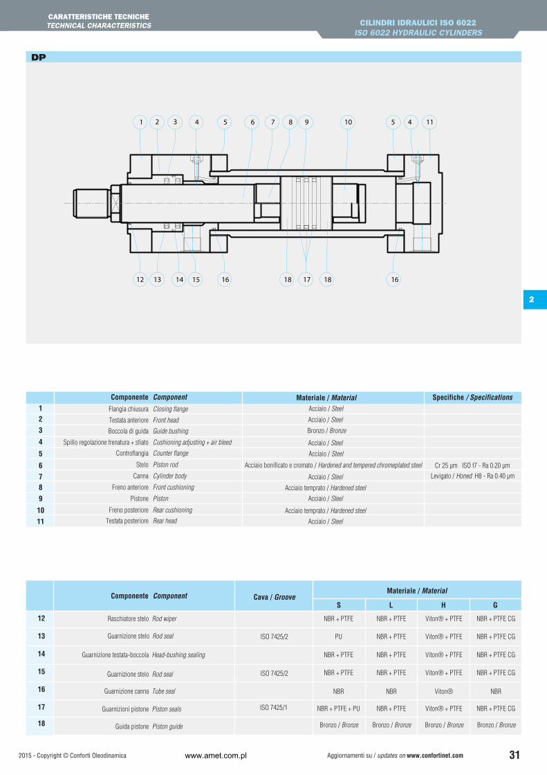
12
13
14
15
16
17
18
ISO 7425/2
ISO 7425/2
NBR + PTFE
NBR + PTFE
NBR + PTFE
NBR + PTFE
NBR + PTFE
NBR + PTFE
NBR + PTFE CG
NBR + PTFE CG
NBR + PTFE CG
Viton® + PTFE
Viton® + PTFE
Viton® + PTFE
PU NBR + PTFE NBR + PTFE CGViton® + PTFE
NBR NBR NBRViton®
NBR + PTFE + PU NBR + PTFE NBR + PTFE CGViton® + PTFEISO 7425/1
Raschiatore stelo
Guarnizione testata-boccola
Guarnizioni pistone
Guarnizione stelo
Guarnizione canna
Guarnizione stelo
Guida pistone
Rod wiper
Head-bushing sealing
Piston seals
Rod seal
Tube seal
Rod seal
Piston guide Bronzo / Bronze Bronzo / Bronze Bronzo / BronzeBronzo / Bronze
Materiale / Material Spec.Componente / Component
Bronzo / Bronze
Acciaio / Steel
Acciaio / Steel
Acciaio / Steel
Acciaio / Steel
Levigato / Honed H8 - Ra 0.40 µm
Cr 25 µm ISO f7 - Ra 0.20 µmAcciaio bonificato e cromato / Hardened and tempered chromeplated steel
Acciaio / Steel
Acciaio / Steel
Acciaio temprato / Hardened steel
Acciaio temprato / Hardened steel
Acciaio / Steel
12
3
4
5
6
78
9
10
11
Materiale / Material Specifiche / Specifications
Flangia chiusura
Boccola di guida
Testata anteriore
Spillo regolazione frenatura + sfiato
Testata posteriore
Stelo
Canna
Pistone
Freno anteriore
Freno posteriore
Componente
Componente
Controflangia
Closing flange
Guide bushing
Front head
Cushioning adjusting + air bleed
Rear head
Piston rod
Cylinder body
Piston
Front cushioning
Rear cushioning
Component
Component
Counter flange
441 9 11107652 53 8
12 13 14 16 17 1615 1818
www.amet.com.pl
2015 - Copyright © Conforti Oleodinamica 32
CILINDRI IDRAULICI ISO 6022ISO 6022 HYDRAULIC CYLINDERS
ANCORAGGIMOUNTINGS
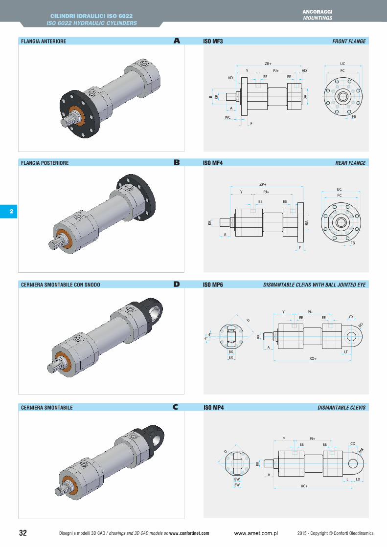
FLANGIA ANTERIORE A ISO MF3 FRONT FLANGE
FLANGIA POSTERIORE B ISO MF4 REAR FLANGE
CERNIERA SMONTABILE CON SNODO D ISO MP6 DISMANTABLE CLEVIS WITH BALL JOINTED EYE
CERNIERA SMONTABILE C ISO MP4 DISMANTABLE CLEVIS
BA
ZP+
PJ+YFC
FB
UC
F
KK
A
EEEE
VD
UC
F
FB
FC
VD
B
WC
Y PJ+
ZB+
BAKK
A
EEEE
4°4°
CX
BXEX
LT
Y PJ+
XO+
KK
A
EEEED
MS
XC+
L LX
CDPJ+Y
KK
A
EEEE
MRD
BWEW
Disegni e modelli 3D CAD / drawings and 3D CAD models on www.confortinet.com
2
www.amet.com.pl

2015 - Copyright © Conforti Oleodinamica 33
CILINDRI IDRAULICI ISO 6022ISO 6022 HYDRAULIC CYLINDERS
ANCORAGGIMOUNTINGS
CERNIERA PROLUNGATA SALDATA CON SNODO S ISO MP5 EXTENDED WELDED CLEVIS WITH BALL JOINTED EYE
CERNIERA PROLUNGATA SALDATA R ISO MP3 EXTENDED WELDED CLEVIS
PERNI INTERMEDI H ISO MT4 INTERMEDIATE TRUNNIONS
PIEDINI E ISO MS2 FEET
4°4°
BXEX
D EE EE
A
KK
Y PJ+CX
LTS
XC+
MS
XC+
LS
CD
EWBW
PJ+Y
KK
A
EEEED
MR
TD UV
TLTL TMBD
XV
Y PJ+
ZB+
VD
KK
A
EEEE
LH
SB
US
TSSC
SESE
SC
SS+XS
VDZB+
PJ+Y
ST
KK
A
EEEE
Disegni e modelli 3D CAD / drawings and 3D CAD models on www.confortinet.com
2
www.amet.com.pl
2015 - Copyright © Conforti Oleodinamica 34
PERNI INTERMEDI H
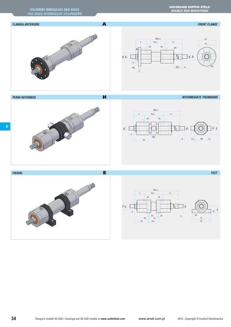
FLANGIA ANTERIORE A FRONT FLANGE
INTERMEDIATE TRUNNIONS
PIEDINI E
CILINDRI IDRAULICI ISO 6022ISO 6022 HYDRAULIC CYLINDERS
ANCORAGGI DOPPIO STELO DOUBLE ROD MOUNTINGS
UC
F
FB
FC
VD
BA
WC
Y PJ1+
BA
VD
WC+
Y+
ZB3++
KK
A
A
KK
EEEE
Y+
ZB3++
Y PJ1+
TD UV
TLTL TMBD
XV
KK
A
A
KK
EEEE
BA
ZB3++
Y+
SCSE
SESC
SS+XS
SB
US
TS
PJ1+Y
LH
KK
A
A
KK
ST
EEEE
Disegni e modelli 3D CAD / drawings and 3D CAD models on www.confortinet.com
2
FEET
www.amet.com.pl
2015 - Copyright © Conforti Oleodinamica Aggiornamenti su / updates on www.confortinet.com 35
INTERMEDIATE TRUNNIONS
CILINDRI IDRAULICI ISO 6022ISO 6022 HYDRAULIC CYLINDERS
DIMENSIONIDIMENSIONS
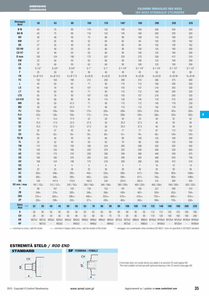
+ = sommare la corsa / add the stroke ++ = sommare il doppio della corsa / add the double of the stroke * = alesaggio non contemplato nella normativa ISO 6022 / bore not specified in ISO 6022 standard
Il terminale stelo con snodo sferico più adatto è la versione CS (vedi pagina 40).The most suitable rod end eye with spherical bearing is the CS version (see page 40).
B f8BA f8BDBWBX
CD H9CX H7D max
EWEXEEF
FBFCL
LSLTLTS
LH h10MRMSPJPJ1SBSCSESTSS
TD f8TLTMTSUCUSUVVDWCXCXOXS
XV min / maxYZBZB3ZP
63
63
38
27
27
32
32
105
32
32
G 1/2”
25
8 x Ø 13.5
132
40
65
40
65
60
38
38
120+
120+
11
15.5
15.5
32
55+
32
25
112
135
155
160
108
4
22
305+
305+
130
187 / 132+
98
244+
315++
265+
75
75
48
35
35
40
40
124
40
40
G 3/4”
28
8 x Ø 13.5
150
50
78
50
78
68
50
50
136+
136+
13.5
17.5
17.5
37
55+
40
32
125
155
175
185
124
4
25
348+
348+
147.5
212 / 137+
107
274+
350++298+
90
90
58
40
40
50
50
148
50
50
G 3/4”
32
8 x Ø 17.5
180
63
95
63
95
80
61.5
61.5
156+
156+
17.5
22.5
22.5
42
55+
50
40
150
185
210
225
148
5
28
395+
395+
170.5
245 / 155+
120
305+
396++
332+
110
110
73
52
52
63
63
175
63
63
G 1”
36
8 x Ø 22
212
71
107
71
107
95
71
71
172+
172+
22
27.5
27.5
52
55+
63
50
180
220
250
265
175
5
32
442+
442+
192.5
280 / 160+
134
340+
440++
371+
132
132
88
60
60
80
80
207
80
80
G 1”
40
8 x Ø 22
250
90
130
90
130
115
90
90
205+
214+
26
30
30
62
60+
80
63
224
270
290
325
218
6
36
520+
520+
230
340 / 180+
153
396+520++
430+
145
145
98
65
65
90
90
255
90
90
G 1 1/4”
40
8 x Ø 26
300
115
155
115
155
135
113
113
208+
208+
30
35.5
35.5
77
61+
90
70
265
325
340
390
260
5
36
580+
580+
254.5
380 / 200+
181
430+
570++
465+
160
160
108
84
84
100
100
270
100
100
G 1 1/4”
45
8 x Ø 26
315
112
157
112
157
145
112
112
235+
240+
33
37.5
37.5
77
79+
100
80
280
340
360
405
280
7
40
617+
617+
265.5
400 / 220+
185
467+
610++
505+
200
200
133
102
102
125
125
330
125
125
G 1 1/4”
56
8 x Ø 33
385
160
216
160
216
170
145
145
278+
280+
40
45
45
87
90+
125
100
335
405
440
480
330
10
45
756+
756+
315
450 / 260+
221550+
720++
596+
250
250
180
130
130
160
160
412
160
160
G 1 1/2”
63
8 x Ø 39
475
200
263
200
263
215
178
178
325+
320+
52
50
50
112
120+
160
125
425
520
540
620
412
12
50
903+
903+
360
540 / 300+
260
652+
840++
703+
320
320
220
162
162
200
200
510
200
200
G 1 1/2”
80
8 x Ø 45
600
250
330
250
330
260
230
230
350+
350+
62
60
60
152
120+
200
160
530
620
675
740
510
14
56
1080+
1080+
425
625 / 325+
310
764+
970++
830+
50 63 80 100 125 140* 160 200 250 320AlesaggioBore
KK
A
CH
KF
A
CH
ESTREMITÀ STELO / ROD END SF FEMMINA / FEMALE STANDARD
2
FEET
ACHKKKF
36 36
28 30
M27x2 M27x2
– M27x2
45 45
34 36
M33x2 M33x2
– M33x2
56 56
43 46
M42x2 M42x2
– M42x2
63 63
52 60
M48x2 M48x2
– M48x2
85 85
65 75
M64x3 M64x3
– M64x3
90 90
75 85
M72x3 M72x3
– M72x3
95 95
85 95
M80x3 M80x3
– M80x3
112 112
110 120
M100x3 M100x3
– M100x3
125 125
140 160
M125x4 M125x4
– M125x4
160 160
180 200
M160x4 M160x4
– M160x4
32 36 40 45 50 56 63 70 80 90 90 100 100 110 125 140 160 180 200 220SteloRod
(mm)
www.amet.com.pl
2015 - Copyright © Conforti OleodinamicaAggiornamenti su / updates on www.confortinet.com 36
8080706065555000
506380100125160200250320
BL
BK
BW1
4
3
1
2
3
4
AlesaggioBore(mm)
DB max (mm)
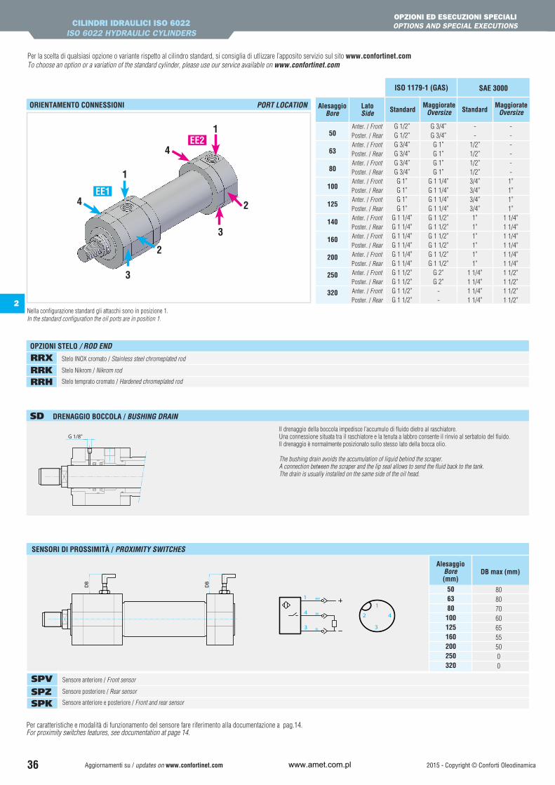
SENSORI DI PROSSIMITÀ / PROXIMITY SWITCHES
DB
DB
2
Il drenaggio della boccola impedisce l’accumulo di fluido dietro al raschiatore. Una connessione situata tra il raschiatore e la tenuta a labbro consente il rinvio al serbatoio del fluido. Il drenaggio è normalmente posizionato sullo stesso lato della bocca olio.
The bushing drain avoids the accumulation of liquid behind the scraper. A connection between the scraper and the lip seal allows to send the fluid back to the tank. The drain is usually installed on the same side of the oil head.
Per la scelta di qualsiasi opzione o variante rispetto al cilindro standard, si consiglia di utlizzare l’apposito servizio sul sito www.confortinet.comTo choose an option or a variation of the standard cylinder, please use our service available on www.confortinet.com
3
1
3
1
2
2
4
4
CILINDRI IDRAULICI ISO 6022ISO 6022 HYDRAULIC CYLINDERS
OPZIONI ED ESECUZIONI SPECIALIOPTIONS AND SPECIAL EXECUTIONS
Per caratteristiche e modalità di funzionamento del sensore fare riferimento alla documentazione a pag.14.For proximity switches features, see documentation at page 14.
ORIENTAMENTO CONNESSIONI PORT LOCATION
SD DRENAGGIO BOCCOLA / BUSHING DRAIN
Sensore anteriore / Front sensor
Sensore posteriore / Rear sensor
Sensore anteriore e posteriore / Front and rear sensor
SPV SPZ SPK
Stelo INOX cromato / Stainless steel chromeplated rod
Stelo Nikrom / Nikrom rod
Stelo temprato cromato / Hardened chromeplated rod
RRX RRK RRH
OPZIONI STELO / ROD END
50
63
80
100
125
140
160
200
250
320
AlesaggioBore
LatoSide Standard Standard
MaggiorateOversize
MaggiorateOversize
Anter. / FrontPoster. / RearAnter. / FrontPoster. / RearAnter. / FrontPoster. / RearAnter. / FrontPoster. / RearAnter. / FrontPoster. / RearAnter. / FrontPoster. / RearAnter. / FrontPoster. / RearAnter. / FrontPoster. / RearAnter. / FrontPoster. / RearAnter. / FrontPoster. / Rear
ISO 1179-1 (GAS) SAE 3000
G 1/2”G 1/2”G 3/4”G 3/4”G 3/4”G 3/4”G 1”G 1”G 1”G 1”
G 1 1/4”G 1 1/4”G 1 1/4”G 1 1/4”G 1 1/4”G 1 1/4”G 1 1/2”G 1 1/2”G 1 1/2”G 1 1/2”
G 3/4”G 3/4”G 1”G 1”G 1”G 1”
G 1 1/4”G 1 1/4”G 1 1/4”G 1 1/4”G 1 1/2”G 1 1/2”G 1 1/2”G 1 1/2”G 1 1/2”G 1 1/2”
G 2”G 2”
--
--
1/2”1/2”1/2”1/2”3/4”3/4”3/4”3/4”1”1”1”1”1”1”
1 1/4”1 1/4”1 1/4”1 1/4”
------1”1”1”1”
1 1/4”1 1/4”1 1/4”1 1/4”1 1/4”1 1/4”1 1/2”1 1/2”1 1/2”1 1/2”
EE1
EE2
Nella configurazione standard gli attacchi sono in posizione 1.In the standard configuration the oil ports are in position 1.
www.amet.com.pl

2015 - Copyright © Conforti Oleodinamica Aggiornamenti su / updates on www.confortinet.com 37
2
CODICE ORDINAZIONE / ORDERING CODE
90DP 125 A 500/ /I campi in cui sono stati inseriti i valori di esempio sono obbligatori.The fields containing sample values are compulsory.
Serie Type DP
Esecuzione speciale / Special version (1) SX
Stelo / Rod
50
63
80
100
125
140 (2)
160
200
250
320
3236404550566370809090
100100110125140160180200220
Alesaggio / Bore
Eventuale 2° stelo / Possible 2nd rod
AncoraggioMounting
MF3
MF4
MP6
MP4
MP5
MP3
MT4
MS2
Flangia anteriore Front flange
Flangia posteriore Rear flange
Cerniera smontabile con snodo Dismantable clevis with ball jointed eye
Cerniera smontabile Dismantable clevis
Cerniera prolungata saldata con snodo Extended welded clevis with ball jointed eye
Cerniera prolungata saldata Extended welded clevis
Perni intermedi Intermediate trunnions
Piedini Feet
A
B
D
C
S
R
H
E
ISO 6022
(3)
Estremità stelo / Rod end (vedi pag. 35 / see page 35)
SF
Filetto maschio Male thread
Filetto femmina Female thread
(standard)
Corsa / Stroke
Indicare in mm / Specify in mm
Frenatura regolabile / Adjustable cushioning (4)
V
Z
K
Senza frenatura / Not cushioned
Anteriore / Front only
Posteriore / Rear only
Anteriore + posteriore / Front and rear
DistanzialeSpacer
Consultare il nostro ufficio tecnicoContact our technical department
Codifica guidata interattiva disponibile su www.confortinet.com Interactive coding wizard on www.confortinet.com
(1) Indicare SX ogni qual volta il cilindro ha opzioni o esecuzioni speciali.Indicare poi nell’apposita casella, a fine codice, il corrispondente codice (vedi pag. 36) seguito da eventuale n. di disegno.
Indicate SX when the cylinder has special options or versions. Then, indicate in the appropriate box, after the ordering code, the corresponding code (see page 36) followed by the drawing’s number, if any.
(2) Non previsto nella norma ISO 6022. Not included in ISO 6022 standard.
(3) Per ancoraggio H (MT4), indicare in coda al codice la dicitura “XV” seguita dal valore della quota XV (vedi pag. 33-34). For H mounting (MT4), indicate at the end of the code the letters “XV” followed by the XV quote value (see page 33-34).
(4) La frenatura non è disponibile per gli alesaggi 250 e 320. The cushioning is not available for bore 250 and 320.
Opzioni/Esecuzioni speciali Special options/versions
(vedi pag. 36) (see page 36)
CILINDRI IDRAULICI ISO 6022ISO 6022 HYDRAULIC CYLINDERS
CODICE DI ORDINAZIONEORDERING CODE
Guarnizioni / Seals (vedi pag. 30 / see page 30)
Standard (olio minerale) Standard (mineral oil)Basso attrito / Low frictionViton® (alte temperature, esteri fosforici)Viton® (high temperature, phosphoric esters)Acqua glicole / HFC-fluid
S
L
H
G
S
www.amet.com.pl