Control unit MC824HR - Nice
88
EN - Instructions and warnings for installation and use IT - Istruzioni ed avvertenze per l’installazione e l’uso FR - Instructions et avertissements pour l’installation et l’utilisation ES - Instrucciones y advertencias para la instalación y el uso DE - Installierungs-und Gebrauchsanleitungen und Hinweise PL - Instrukcje i ostrzeżenia do instalacji i użytkowania NL - Aanwijzingen en aanbevelingen voor installatie en gebruik Moon Control unit MC824HR
Transcript of Control unit MC824HR - Nice

EN - Instructions and warnings for installation and use
IT - Istruzioni ed avvertenze per l’installazione e l’uso
FR - Instructions et avertissements pour l’installation et l’utilisation
ES - Instrucciones y advertencias para la instalación y el uso
DE - Installierungs-und Gebrauchsanleitungen und Hinweise
PL - Instrukcje i ostrzeżenia do instalacji i użytkowania
NL - Aanwijzingen en aanbevelingen voor installatie en gebruik
MoonControl unitMC824HR

EN
English – 1
ENGLISH
ContentsGENERAL SAFETY WARNINGS AND PRECAUTIONS. . . . . . . . . . . . . . . 1Safety warnings . . . . . . . . . . . . . . . . . . . . . . . . . . . . . . . . . . . . . . . . . . . . . . . 1Installation warnings . . . . . . . . . . . . . . . . . . . . . . . . . . . . . . . . . . . . . . . . . . . 1Safety warnings . . . . . . . . . . . . . . . . . . . . . . . . . . . . . . . . . . . . . . . . . . . . . . . 1
1 - PRODUCT DESCRIPTION AND INTENDED USE . . . . . . . . . . . . . . . . 1
2 - INSTALLATION . . . . . . . . . . . . . . . . . . . . . . . . . . . . . . . . . . . . . . . . . . . 12.1 - Preliminary checks for installation . . . . . . . . . . . . . . . . . . . . . . . . . . . . . 12.2 - Product application limits . . . . . . . . . . . . . . . . . . . . . . . . . . . . . . . . . . . 22.3 - Typical system . . . . . . . . . . . . . . . . . . . . . . . . . . . . . . . . . . . . . . . . . . . 22.4 - Installation of control unit. . . . . . . . . . . . . . . . . . . . . . . . . . . . . . . . . . . . 2
3 - ELECTRICAL CONNECTIONS . . . . . . . . . . . . . . . . . . . . . . . . . . . . . . . 23.1 - Description of electrical connections . . . . . . . . . . . . . . . . . . . . . . . . . . . 2 3.2 - Electrical connections of MC824HR control unit . . . . . . . . . . . . . . . . . . 23.3 - Connection of other devices to MC824HR . . . . . . . . . . . . . . . . . . . . . . 33.4 - Connected device address assignment to MC824HR . . . . . . . . . . . . . . 33.5 - Initial start-up and electrical connections . . . . . . . . . . . . . . . . . . . . . . . . 33.6 - Learning of the devices connected to MC824HR . . . . . . . . . . . . . . . . . 33.7 - Mechanical limiter position learning . . . . . . . . . . . . . . . . . . . . . . . . . . . . 3 3.7.1 - Learning in automatic mode . . . . . . . . . . . . . . . . . . . . . . . . . . . 3 3.7.2 - Learning in manual mode . . . . . . . . . . . . . . . . . . . . . . . . . . . . . 4 3.7.3 - Learning in combined mode . . . . . . . . . . . . . . . . . . . . . . . . . . . 43.8 - Checking movement of gate leafs . . . . . . . . . . . . . . . . . . . . . . . . . . . . . 4
4 - TESTING AND COMMISSIONING . . . . . . . . . . . . . . . . . . . . . . . . . . . . 44.1 - Testing . . . . . . . . . . . . . . . . . . . . . . . . . . . . . . . . . . . . . . . . . . . . . . . . . 44.2 - Commissioning . . . . . . . . . . . . . . . . . . . . . . . . . . . . . . . . . . . . . . . . . . . 4
5 - PROGRAMMING . . . . . . . . . . . . . . . . . . . . . . . . . . . . . . . . . . . . . . . . . . 55.1 - Level one programming (ON-OFF functions) . . . . . . . . . . . . . . . . . . . . . 55.2 - Level two programming (adjustable parameters) . . . . . . . . . . . . . . . . . . 65.3 - Special functions. . . . . . . . . . . . . . . . . . . . . . . . . . . . . . . . . . . . . . . . . . 75.4 - Deletion of memory . . . . . . . . . . . . . . . . . . . . . . . . . . . . . . . . . . . . . . . . 7
6 - WHAT TO DO IF… (troubleshooting guide) . . . . . . . . . . . . . . . . . . . . 8
7 - FURTHER DETAILS. . . . . . . . . . . . . . . . . . . . . . . . . . . . . . . . . . . . . . . . 97.1 - Connecting a radio receiver. . . . . . . . . . . . . . . . . . . . . . . . . . . . . . . . . . 97.2 - Connecting Oview programming unit. . . . . . . . . . . . . . . . . . . . . . . . . . . 97.3 - Connecting the Solemyo solar energy system . . . . . . . . . . . . . . . . . . . . 97.4 - Connecting model PS324 buffer battery . . . . . . . . . . . . . . . . . . . . . . . . 9
8 - PRODUCT MAINTENANCE . . . . . . . . . . . . . . . . . . . . . . . . . . . . . . . . 10
PRODUCT DISPOSAL . . . . . . . . . . . . . . . . . . . . . . . . . . . . . . . . . . . . . . . 10
TECHNICAL CHARACTERISTICS OF THE PRODUCT . . . . . . . . . . . . . 10
CE DECLARATION OF CONFORMITY . . . . . . . . . . . . . . . . . . . . . . . . . . . . I
Instructions and warnings for the user . . . . . . . . . . . . . . . . . . . . . . . . . . VImages . . . . . . . . . . . . . . . . . . . . . . . . . . . . . . . . . . . . . . . . . . . . . . . . . . . XII
MC824HR is an electronic control unit for the automation of gates with swing-ing leaves fitted with Toona series motors model 5624I (see paragraph “2.2 Product application limits). IMPORTANT! – Any other use than as speci-fied herein or in environmental conditions other than as stated in this manual is to be considered improper and is strictly prohibited!
The control unit is ready for connection to devices belonging to the Opera sys-tem, the Bluebus system and the Solemyo solar energy supply system.If powered from the mains, it can house a buffer battery (model PS324, option-al accessory), which ensures that the automation can perform a number of manoeuvres for several hours in the event of a power failure.Other available accessories include the dedicated receivers with “SM” fitting (SMXI, OXI, etc.).
PRODUCT DESCRIPTION AND INTENDED USE1
Safety warnings
• IMPORTANT! – This manual contains important instructions and warn-ings for personal safety. Incorrect installation could cause serious physical injury. Read all parts of the manual carefully before starting work. If in doubt, interrupt installation and contact the Nice Service Centre for clarifications.
• IMPORTANT! – Important instructions: keep this manual in a safe place to enable future product maintenance and disposal procedures.
• IMPORTANT! – Under the latest European legislation, automatic door and gate installations must be compliant with the standards specified in Directive 2006/42/EC (formerly 98/37/EC) (the Machinery Directive) and the standards EN 12445, EN 12453, EN 12635 and EN 13241-1 in particular, which enable conformity of the automated functionality to be de clared. In the light of the above, all work involving installation, connection, testing and maintenance of the product must be carried out exclusively by qualified and competent technicians!
Installation warnings
• Before commencing installation, check that the product is suitable for the intended kind of use (see paragraph 2.2 “Limits of use” and “Product technical specifications”). If not suitable, do NOT proceed with installation.
• The contents of this manual refer to a standard system as described in fig. 2a.• All installation and maintenance work must be carried out with the au to-
mation system disconnected from the electricity supply. If the power discon nection device cannot be seen from where the automation system is po sitioned, then before starting work a notice must be attached to the discon-nection device bearing the words “CAUTION! MAINTENANCE IN PRO GRESS”.
• On the power line to the system, install a device for disconnection from the power mains with a gap between contacts that assures complete disconnec-tion in the conditions of overvoltage category III.
• Connect the control unit to an electric power line equipped with an earthing system.• During installation, handle the product with care, avoiding the risk of crushing,
impact, dropping or contact with any type of liquid. Never place the product near sources of heat or expose to naked flames. This may damage prod-uct components and cause malfunctions, fire or hazardous situations. If this oc curs, suspend installation immediately and contact the Nice Service Centre.
• Never make modifications to any part of the product. Operations other than as specified can only cause malfunctions. The manufacturer declines all liability for damage caused by makeshift modifications to the product.
• The product’s packaging materials must be disposed of in full compliance with local regulations.
Safety warnings
• The product should not be used by children or people with impaired physical, sensorial or mental capacities or who have not received adequate training in the safe use of the product.
• In the vicinity of the automation children must be supervised to ensure that they do not play with it.
• Do not allow children to play with the fixed control devices. Keep remote control devices out of the reach of children.
GENERAL SAFETY WARNINGS AND PRECAUTIONS
2.1 - Preliminary checks for installation
Before proceeding with installation, check the condition of the product compo-nents, suitability of the selected model and conditions of the intended installa-tion environment:• Ensure that all material used is in perfect condition and suitable for use.• Ensure that all conditions of use remain within the limits of product applica-
tion (paragraph 2.2) and within the limit values stated in the “Product techni-cal specifications”.
• Ensure that the selected installation environment is compatible with the over-all dimensions of the product (fig. 1).
• Ensure that the selected surfaces for product installation are solid and guar-antee a stable fixture.
• Make sure that the fixing zone is not subject to flooding. If necessary, mount the product raised from the ground.
INSTALLATION2

EN
2 – English
ELECTRICAL CONNECTIONS3The electrical connection of the various devices (photocells, digital keyboard, transponder card readers, etc.) contained in the automation with the control unit must be made by means of the Nice “Bluebus” system.
3.1 - Description of electrical connections (fig. 6)
AERIAL input for the radio receiver aerial
FLASH output for 1 flashing light with 12V (maximum 21W) bulb. [*]
ELS output for 12Vac (maximum 15VA) electric lock. [*]
S.C.A. “Open Gate Light”: output for 1 indication lamp (24V maximum 4W). [*]
BLUEBUS input for compatible devices (MOFB, MOFOB, MOB and MOTB); they are connected in parallel using two conductors through which both the electricity supply and the communication signals travel; no polarity needs to be observed. The electrical connection to be used is of the parallel type and no polarity needs to be observed. During the learning stage, the control unit will recognise individually all devices connected to it thanks to a unique code. Each time a device is added or eliminated, it will be necessary to make the control unit perform the learning operation (see paragraph 3.6).
STOP input for devices that cause the immediate interruption of the manoeuvre in progress (with a short reverse run); NO and NC con-tacts, as well as devices with 8.2 kΩ constant resistance output (sensitive edges) can be connected to this input. Each device con-nected to this input is recognised individually by the control unit during the learning stage (paragraph 3.6); in this stage, if the con-trol unit detects any variations with respect to the learned state, it causes a STOP. One or more devices of the same or different kinds can be connected to this input:
– connect a number of NO devices in parallel without quantity lim-its;
– several NC devices can be connected in series, with no limits as to quantity;
– connect 2 devices with 8.2 kΩ constant resistance output in par-allel. If there are more than 2 devices, they must be connected in a cascade with just one 8.2 kΩ termination resistance;
– connect 2 NO and NC devices in parallel, placing a 8.2 kΩ resistance in series on the NC contact (this also allows for a com-bination of three devices NO - NC and 8.2 kΩ)
P.P. input for devices which control Step-by-Step manoeuvres. NO contacts can be connected to this input
OPEN input for devices which control only opening manoeuvre. NO contacts can be connected to this input
CLOSE input for devices which control only closure manoeuvre. NO contacts can be connected to this input
ENC1 input encoder – gearmotor 1 (terminal 1, 2); it is not necessary to observe any polarity
ENC2 input encoder – gearmotor 2 (terminal 4, 5); it is not necessary to observe any polarity
M1 output for gearmotor 1 (terminal 7, 8, 9)
M2 output for gearmotor 2 (terminal 10, 11, 12)
[*] The FLASH, ELS and S.C.A. outputs can be programmed with other functions (see “TABLE 4 - 1st level functions”; or via Oview programmer, see chapter 7.2).
3.2 - Electrical connections of MC824HR control unit
After mounting the control unit box and preparing the electrical cable holes (chapter 2.4 and fig. 3), make the electrical connections:
IMPORTANT!
– All electrical connections must be made with the unit disconnected from the mains power supply and with the buffer battery disconnected, if present in the automation.– Connections must be made exclusively by qualified personnel.– The electrical power line must be fitted with a device that enables complete disconnection of the automation from the mains. The disconnection device must have a gap between contacts that ensures complete disconnection in the conditions of overvoltage category III, in compliance with installation regula-tions. If necessary, this device guarantees rapid and safe disconnection from the mains, and therefore should be located in view of the automation. However, if located in a concealed position, it must have a system that blocks against inadvertent or unauthorised reconnection to prevent all risks. The disconnec-tion device is not supplied with the product.
01. First connect the electric power cable (fig. 4) and secure by means of the cable clamp;
02. Then connect the electric cables of motors M1 and M2, observing the symbols on the label (fig. 5):
• Ensure that the space around the product enables easy and safe access.• Make sure that all the electrical cables used are of the type listed in Table 1.• Make sure that the automation is provided with mechanical stops on both
closing and opening.
2.2 - Product application limits
The MC824HR control unit may only be used with the Toona gearmotors model 5624I; these motors are reversible: i.e. it is possible to manually move the leaves of the gate without having to manually release the gearmotor. Thanks to a sen-sor inserted in the motor, the control unit is able to detect the manual move-ment of the leaves while correctly managing the subsequent manoeuvres; this is necessary to avoid the leaves hitting the opening and closing mechanical stops. Caution! - If the control unit is not correctly powered or if the “stand By all” function is active, the manual movement of the leaves is not detected.
2.3 - Typical system
Fig. 2a shows an example of an automation system set up with Nice components:
a - Control unitb - Gearmotorc - Flashing lightd - Photocelle - Digital keyboard - Transponder reader - Key selectorf - Photocell postg - Opening mechanical stops
h - Closure mechanical stopsi - Electric lock
These parts are positioned according to a typical standard layout. With refer-ence to fig. 2a, locate the approximate position for installation of each com-ponent making up the system. Important – Before installation, prepare the electrical cables needed for your system, referring to fig. 2b and “Table 1 - Technical characteristics of electrical cables”.
Important – During installation of ducting for electrical cables and the introduc-tion of cables into the control unit enclosure, be aware that due to possible water deposits in the junction boxes, the connecting ducts may form conden-sation inside the control unit which is liable to damage the electronic circuits.
2.4 - Installation of control unit
To mount the control unit, proceed as shown in fig. 3:01. Open the control unit box by undoing the relevant screws (fig. 3-A);02. Prepare the electrical cable routing holes (fig. 3-B);03. Mount the box (fig. 3-C);04. The electrical connections can now be made: see chapter 3.Important! – To prepare the inlets for the electrical cable ducting, holes must be drilled in the lower side of the control unit box. Note – If necessary, the lateral cable inlet may be used, but only with the aid of suitable duct fittings.To install the other devices present in the automation, refer to the relevant instruction manuals.
Connection Cable type Maximum admissible length
A: CONTROL UNIT POWER cable 1 cable 3 x 1,5 mm2 30 m (note 1)
B: FLASHING LIGHT with aerial cable 1 cable 2 x 0,5 mm2 20 m 1 shielded cable type RG58 20 m (less than 5 m recommended)
C: BLUEBUS DEVICES cable 1 cable 2 x 0,5 mm2 20 m (note 2)
D: KEY-OPERATED SELECTOR SWITCH cable 2 cables 2 x 0,5 mm2 (note 3) 50 m
E: GEARMOTOR POWER cable 1 cable 3 x 1,5 mm2 (note 4) 10 m
F: ENCODER CONNECTION cable 1 cable 2 x 1 mm2 (note 4) 10 m
G: ELECTRIC LOCK CONNECTION 1 cable 2 x 1 mm2 10 m
Note 1 – If the power cable is longer than 30 m, a cable with a larger cross-section is required (3 x 2.5 mm2) and safety earthing is necessary in the vicinity of the automation.Note 2 – If the Bluebus cable is longer than 20 m (up to max. 40 m), a cable with a larger cross-section is required (2 x 1 mm2).Note 3 – These 2 cables can be replaced by a single 4 x 0.5 mm2 cable.Note 4 – These 2 cables can be replaced by a single 5 x 1.5 mm2 cable.
IMPORTANT! – The cables used must be suited to the installation environment.
TABLE 1 - Technical specifications of electrical cables (fig. 2b)
EN
English – 3
through the self-learning procedure and detect possible faults. For this reason it is necessary to perform self-learning every time a new device is added or an existing device is removed.To indicate when the self-learning procedure is required, LEDs L1 and L2 on the control unit (fig. 7) emit a number of slow flashes:01. Press and hold down and “Set” keys at the same time (fig. 7).02. Release the keys when LEDs L1 and L2 start flashing quickly (after approx.
3 seconds).03. Wait a few seconds for the control unit to complete the device learning
phase.04. At the end of this phase, the “Stop” LED must be lit and LEDs “L1” and
“L2” must be turned off (LEDs L3 and L4 may start flashing).
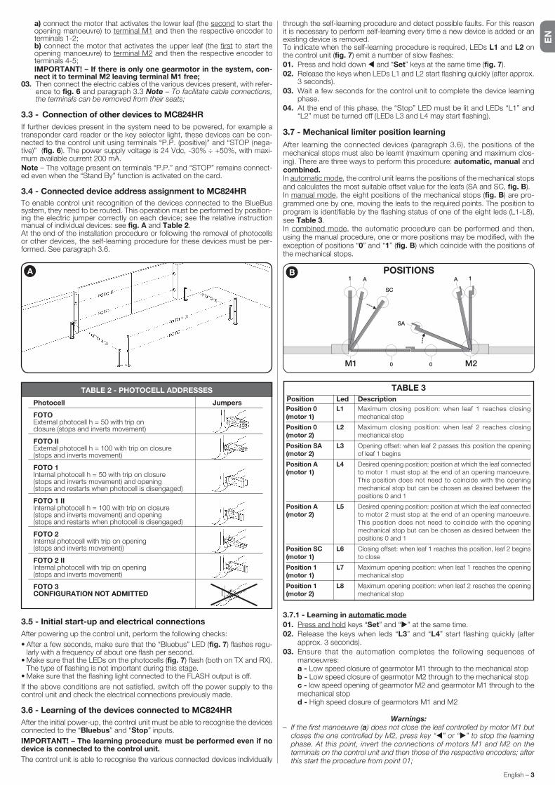
3.7 - Mechanical limiter position learning
After learning the connected devices (paragraph 3.6), the positions of the mechanical stops must also be learnt (maximum opening and maximum clos-ing). There are three ways to perform this procedure: automatic, manual and combined.In automatic mode, the control unit learns the positions of the mechanical stops and calculates the most suitable offset value for the leafs (SA and SC, fig. B).In manual mode, the eight positions of the mechanical stops (fig. B) are pro-grammed one by one, moving the leafs to the required points. The position to program is identifiable by the flashing status of one of the eight leds (L1-L8), see Table 3.In combined mode, the automatic procedure can be performed and then, using the manual procedure, one or more positions may be modified, with the exception of positions “0” and “1” (fig. B) which coincide with the positions of the mechanical stops.
3.7.1 - Learning in automatic mode
01. Press and hold keys “Set” and “ ” at the same time.02. Release the keys when leds “L3” and “L4” start flashing quickly (after
approx. 3 seconds).03. Ensure that the automation completes the following sequences of
ma noeuvres: a - Low speed closure of gearmotor M1 through to the mechanical stop b - Low speed closure of gearmotor M2 through to the mechanical stop c - low speed opening of gearmotor M2 and gearmotor M1 through to the
mechanical stop d - High speed closure of gearmotors M1 and M2
Warnings:– If the first manoeuvre (a) does not close the leaf controlled by motor M1 but
closes the one controlled by M2, press key “ ” or “ ” to stop the learning phase. At this point, invert the connections of motors M1 and M2 on the terminals on the control unit and then those of the respective encoders; after this start the procedure from point 01;
a) connect the motor that activates the lower leaf (the second to start the opening manoeuvre) to terminal M1 and then the respective encoder to terminals 1-2;
b) connect the motor that activates the upper leaf (the first to start the opening manoeuvre) to terminal M2 and then the respective encoder to terminals 4-5;
IMPORTANT! – If there is only one gearmotor in the system, con-nect it to terminal M2 leaving terminal M1 free;
03. Then connect the electric cables of the various devices present, with refer-ence to fig. 6 and paragraph 3.3 Note – To facilitate cable connections, the terminals can be removed from their seats;
3.3 - Connection of other devices to MC824HR
If further devices present in the system need to be powered, for example a transponder card reader or the key selector light, these devices can be con-nected to the control unit using terminals “P.P. (positive)” and “STOP (nega-tive)” (fig. 6). The power supply voltage is 24 Vdc, -30% ÷ +50%, with maxi-mum available current 200 mA.Note – The voltage present on terminals “P.P.” and “STOP” remains connect-ed even when the “Stand By” function is activated on the card.
3.4 - Connected device address assignment to MC824HR
To enable control unit recognition of the devices connected to the BlueBus system, they need to be routed. This operation must be performed by position-ing the electric jumper correctly on each device; see the relative instruction manual of individual devices: see fig. A and Table 2.At the end of the installation procedure or following the removal of photocells or other devices, the self-learning procedure for these devices must be per-formed. See paragraph 3.6.
3.5 - Initial start-up and electrical connections
After powering up the control unit, perform the following checks:
• After a few seconds, make sure that the “Bluebus” LED (fig. 7) flashes regu-larly with a frequency of about one flash per second.
• Make sure that the LEDs on the photocells (fig. 7) flash (both on TX and RX). The type of flashing is not important during this stage.
• Make sure that the flashing light connected to the FLASH output is off.
If the above conditions are not satisfied, switch off the power supply to the control unit and check the electrical connections previously made.
3.6 - Learning of the devices connected to MC824HR
After the initial power-up, the control unit must be able to recognise the devices connected to the “Bluebus” and “Stop” inputs.
IMPORTANT! – The learning procedure must be performed even if no device is connected to the control unit.
The control unit is able to recognise the various connected devices individually
A
TABLE 2 - PHOTOCELL ADDRESSES
Photocell Jumpers
FOTO External photocell h = 50 with trip on closure (stops and inverts movement)
FOTO II External photocell h = 100 with trip on closure (stops and inverts movement)
FOTO 1 Internal photocell h = 50 with trip on closure (stops and inverts movement) and opening (stops and restarts when photocell is disengaged)
FOTO 1 II Internal photocell h = 100 with trip on closure (stops and inverts movement) and opening (stops and restarts when photocell is disengaged)
FOTO 2 Internal photocell with trip on opening (stops and inverts movement))
FOTO 2 II Internal photocell with trip on opening (stops and inverts movement)
FOTO 3 CONFIGURATION NOT ADMITTED
TABLE 3
Position Led Description
Position 0(motor 1)
Position 0(motor 2)
Position SA(motor 2)
Position A(motor 1)
Position A(motor 2)
Position SC(motor 1)
Position 1(motor 1)
Position 1(motor 2)
Maximum closing position: when leaf 1 reaches closing mechanical stop
Maximum closing position: when leaf 2 reaches closing mechanical stop
Opening offset: when leaf 2 passes this position the opening of leaf 1 begins
Desired opening position: position at which the leaf connected to motor 1 must stop at the end of an opening manoeuvre. This position does not need to coincide with the opening mechanical stop but can be chosen as desired between the positions 0 and 1
Desired opening position: position at which the leaf connected to motor 2 must stop at the end of an opening manoeuvre. This position does not need to coincide with the opening mechanical stop but can be chosen as desired between the positions 0 and 1
Closing offset: when leaf 1 reaches this position, leaf 2 begins to close
Maximum opening position: when leaf 1 reaches the opening mechanical stop
Maximum opening position: when leaf 2 reaches the opening mechanical stop
L1
L2
L3
L4
L5
L6
L7
L8
0
1 1A
SC
SA
A
0M1 M2
B POSITIONS

EN
4 – English
These are the most important phases of automation set-up for ensuring maxi-mum system safety. The test can also be performed as a periodic check of automation devices. Testing and commissioning of the automation must be performed by skilled and qualified personnel, who are responsible for the tests required to verify the solutions adopted according to the risks present, and for ensuring observance of all legal provisions, standards and regulations, and in particular all requirements of the standard EN 12445, which establishes the test methods for checking automations for doors and gates. The additional devi-ces must undergo a specific test for functionality and correct interaction with MC824HR. Refer to the instruction manuals of the individual devices.
4.1 - Testing
The sequence of operations to be performed for testing and described below refers to a typical system (fig. 2):1 Ensure that everything stated in the “Installation warnings” chapter has
been observed.2 Release the gearmotors for manual operation as described in the relevant
instruction manual. Pushing at the prescribed point for manual operation, check that it is possible to open and close the leafs with a force lower than 390 N.
3 Lock the gearmotors (see relevant instruction manual).4 Using the control devices (transmitter, key-operated selector switch or con-
trol pushbuttons, etc.), perform tests of opening, closing and stopping the gate, and ensure that leaf movement corresponds to specifications. Test several times to check for leaf movement and any defects in assembly or adjustment and any possible points of friction.
5 Check operation of all system safety devices one at a time (photocells, sen-sitive edges, etc.). Each time a device is activated the “BLUEBUS” LED on the control unit must flash rapidly twice to confirm acknowledgement of the event.
6 If hazardous situations generated by the moving leafs are protected by means of impact force limitation, measure the force as specified in the stan-dard EN 12445. If gearmotor force control is used as auxiliary function with the system for reduction of impact force, test and identify the setting that obtains the best results.
4.2 - Commissioning
Commissioning can only be performed after positive results of all test phases.
1 Prepare the automation technical documentation, which must contain the following documents: overall drawing of the automation, electrical wiring diagram, risk assessment and solutions adopted, manufacturer’s declara-tion of conformity for all devices used and installer’s declaration of confor-mity.
2 Apporre sul cancello una targhetta contenente almeno i seguenti dati: tipo di automazione, nome e indirizzo del costruttore (responsabile della “messa in servizio”), numero di matricola, anno di costruzione e marchio “CE”.
3 Affix a dataplate on the door, specifying at least the following data: type of automation, name and address of manufacturer (responsible for commissio-ning), serial number, year of construction and CE mark.
4 Compile the “Operation manual” for the automation and forward it to the owner.
5 Compile the form “Maintenance schedule” containing all maintenance instructions for all devices in the automation and forward it to the owner.
TESTING AND COMMISSIONING4
– If the first two manoeuvres (a and b) are not “closing” but are “opening”, press key “ ” or “ ” to stop the learning phase. At this point, on the gear-motor that completed the opening manoeuvre, invert the polarity of the two wires of gearmotor M1 (terminals 7 and 9) and of M2 (terminals 10 and 12) and then start the procedure from point 01;
04. At the end of the Closing manoeuvre of the 2 motors (d), leds “L3” and “L4” turn off to indicate the that the procedure has been completed cor-rectly.
Warnings:– During the automatic learning procedure, if a photocell trips or a device con-
nected to the “stop” input is activated, the procedure is interrupted and led L1 starts flashing. To resume the learning process, the procedure must be started again from point 01;
– The automatic learning procedure can be repeated at any time, also after installation; for example following modifications to the position of the mechanical stops.
3.7.2 - Learning in manual mode
Caution! – From step 03 onwards:– to move from led L1 to L8, briefly press key or (the led flashes to indi-
cate the current position);– to move the motor in one or the other direction, press and hold key or .
01. Press and hold keys “Set” and “ ” at the same time.
02. Release the keys when led “L1” starts flashing (after approx. 1 second); Note – After 3 seconds have elapsed, if the keys “Set” and “ ” are not released, the “automatic learning” procedure is started up, and not the manual procedure.
03. • LED L1 flashes: position 0 of M1
To bring motor 1 to position 0 (fig. B): press and hold down the or keys. On reaching the position, release the key to stop the manoeuvre. To memorise the position, press and hold down the “Set” key for at least 3 seconds and then release it (after 2 seconds LED L1 remains on and on releasing the “Set” key LED L2 begins flashing).
• LED L2 flashes: position 0 of M2 To bring motor 2 to position 0 (fig. B): press and hold down the or
keys. On reaching the position, release the key to stop the manoeuvre. To memorise the position, press and hold down the “Set” key for at least 3 seconds and then release it (after 2 seconds LED L2 remains on and on releasing the “Set” key LED L3 begins flashing).
• LED L3 flashes: position SA of M2 To bring motor 2 to position SA (fig. B): press and hold down the or
keys. On reaching the position, release the key to stop the manoeuvre. To memorise the position, press and hold down the “Set” key for at least 3 seconds and then release it (after 2 seconds LED L3 remains on and on releasing the “Set” key LED L4 begins flashing).
• LED L4 flashes: position A of M1 To bring motor 1 to position A (fig. B): press and hold down the or
keys. On reaching the position, release the key to stop the manoeuvre. To memorise the position, press and hold down the “Set” key for at least 3 seconds and then release it (after 2 seconds LED L4 remains on and on releasing the “Set” key LED L5 begins flashing).
• LED L5 flashes: position A of M2 To bring motor 2 to position A (fig. C): press and hold down the or
keys. On reaching the position, release the key to stop the manoeuvre. To memorise the position, press and hold down the “Set” key for at least 3 seconds and then release it (after 2 seconds LED L5 remains on and on releasing the “Set” key LED L6 begins flashing).
• LED L6 flashes: position SC of M1 To bring motor 1 to position SA (fig. C): press and hold down the or
keys. On reaching the position, release the key to stop the manoeuvre. To memorise the position, press and hold down the “Set” key for at least 3 seconds and then release it (after 2 seconds LED L6 remains on and on releasing the “Set” key LED L7 begins flashing).
• LED L7 flashes: position 1 of M1 To bring motor 1 to position 1 (fig. C): press and hold down the or
keys. On reaching the position, release the key to stop the manoeuvre. To memorise the position, press and hold down the “Set” key for at least 3 seconds and then release it (after 2 seconds LED L7 remains on and on releasing the “Set” key LED L8 begins flashing).
• LED L8 flashes: position 1 of M2
To bring motor 2 to position 1 (fig. C): press and hold down the or keys. On reaching the position, release the key to stop the manoeuvre. To memorise the position, press and hold down the “Set” key for at least 3 seconds and then release it to exit programming (after 2 seconds LED L8 remains on until the “Set” key is released).
Note – Manually programming a system with one gearmotor: proceed as described at the beginning of this paragraph from step 01 to step 03, proceed as follows:- program the positions relating to LEDs L1 (0 of M1) and L7 (1 of M1)
as follows: keep the “Set” key pressed for at least 3 sec. and then release it (after 2 sec. the LED stays on and, upon releasing the “Set” key, the next LED starts flashing).
- do not program the positions relating to LEDs L3 (SA of M2) - L4 (A of M1) - L6 (SC of M1)
- to move between positions, briefly press the or key.
3.7.3 - Learning in combined mode
Perform this procedure after completing the automatic learning cycle:01. Press and hold keys “Set” and “ ” at the same time.02. Release the keys when led “L1” starts flashing (after approx. 1 second);
Note – After 3 seconds have elapsed, if the keys “Set” and “ ” are not released, the “automatic learning” procedure is started up, and not the manual procedure.
03. Briefly press key “ ” or “ ” to move the flashing led (L1-L8) to the position to be programmed and proceed for each position, as described in step 03 of the manual learning procedure (paragraph 3.7.2).
Repeat this operation for all other positions to be modified.To complete the manual learning process, press key “ ” repeatedly to move the led that flashing beyond position L8.
3.8 - Checking movement of gate leafs
At the end of the learning procedure, it is advisable to make the control unit perform a few opening and closing manoeuvres to ensure that the gate moves correctly and to check for installation or setting defects.
01. Press “Open”. Verify correct offset of the leafs on opening and ensure that the opening manoeuvre comprises the acceleration phase, the constant speed phase and the deceleration phase. At the end of the manoeuvre, the leafs must stop a few centimetres from the opening mechanical stop.
02. Press the “Close” key and check that the closure manoeuvre includes the acceleration, constant speed and deceleration phases. Check that the leaf closure offset is correct. At the end of the manoeuvre, the leafs must be perfectly closed on the mechanical closure stop.
03. Make sure that the flashing light flashes at intervals of 0.5 sec on, 0.5 sec off during manoeuvres.

EN
English – 5
5.1 - Level one programming (ON-OFF functions)
All the first level functions can be programmed by default on “OFF” except for the always close function which is “ON”. The functions may be changed at any time. To check the various functions see Table 4. For the programming procedure see Table 5.
IMPORTANT – In the programming procedure, the maximum time interval that can elapse between activation of one key and the next is 10 seconds. When this time elapses, the procedure terminates automatically, memorising the modifications made up until then.
The control unit has 3 keys OPEN ( ), STOP (SET), CLOSE ( ) that can be used both for controlling the unit during testing and for programming the avail-able functions.The programmable functions available are divided into 2 levels and their relative operating status is displayed by means of the 8 LEDs (L1…L8) on the control unit (LED lit = function active; LED off = function not active).
Use the programming keys:
OPEN ( ): – key for controlling gate opening; – selection key during programming.
STOP/SET: key for stopping a manoeuvre; if pressed for more than 5 sec-onds, it enables entry to programming mode.
CLOSE ( ): – key for controlling gate closure; – selection key during programming.
PROGRAMMING5
6 Before commissioning the automation, ensure that the owner is adequately informed of all associated risks and hazards.
For all the above-mentioned documentation, Nice provides instruction manuals, guides and pre-filled forms through its technical support service. Also see: www.nice-service.com
TABLE 4 - First level functions
LED Function Description
L1 Automatic closure
L2 Reclose after photo
L3 Always close (*)
L4 Stand by (Bluebus)
L5 Electric lock/Courtesy light
L6 Pre-flash
L7 “Close” becomes “Partial open 1”
L8 Automatic 1
Function ACTIVE: after an opening movement, there is a pause (equal to the programmed time) after which the control unit automatic initiates a closure movement. The factory setting for the Pause time is 30 sec.
Function NOT ACTIVE: function is “semiautomatic” type.
Function ACTIVE: if the photocells are activated during the opening or closing manoeuvre, the pause time is reduced to 5 seconds regardless of the programmed pause time.
With “automatic closure” disabled, if the photocells are activated during closure the “automatic closure” is activated with the programmed “pause time”.
Function ACTIVE: in the event of a power failure, even of short duration, when power is restored the control unit detects gate open and automatically starts a closure manoeuvre, preceded by 5 seconds of pre-flashing.
Function NOT ACTIVE: when power is restored the gate remains where it is.
Function ACTIVE: 1 minute after the end of the manoeuvre, the control unit turns off the “Bluebus” output (connected devices) and all the LEDs apart from the Bluebus LED which will flash more slowly. When the control unit receives a command normal operation is restored (with a short delay). This function has the purpose of reducing consumption, an important aspect with battery or photovoltaic panel power supply.
Function ACTIVE: the “electric lock” output switches its operation to “courtesy light”.
Function NOT ACTIVE: the output operates as an electric lock.
Function ACTIVE: a 3 second pause can be added between the flashing light signal and the start of the manoeuvre to provide advance warning of a hazard situation.
Function NOT ACTIVE: flashing light signal coincides with the start of the manoeuvre.
Function ACTIVE: the “Close” input of the control unit switches operation mode to “Partial Open 1”
ACTIVE Function: with the gate open and with “automatic closing active”, the commands coming from the inputs and the Radio receiver are disabled during the pause time. The operation of these commands is restored when the pause time elapses, immediately after the closing manoeuvre has begun.
NOT ACTIVE Function: the commands also work during the pause time.
TABLE 5 – Programming procedure (first level functions)
01. Press and hold down the “Set” key for approx. 3 seconds;
02. Release the key when LED “L1” starts flashing;
03. Press the “ ” or “ ” key to move the flashing LED to the LED representing the function to be modified;
04. Press “Set” to change the status of the function: (short flash = OFF; long flash = ON);
05. Wait 10 seconds (maximum time) to exit the programming mode.
Note – During this procedure, points 03 and 04 need to be repeated when programming other functions to “ON” or “OFF” during the phase itself.
SET
SET
SETL1
or
3 s
10 s
(*) Function active by default
EN
6 – English
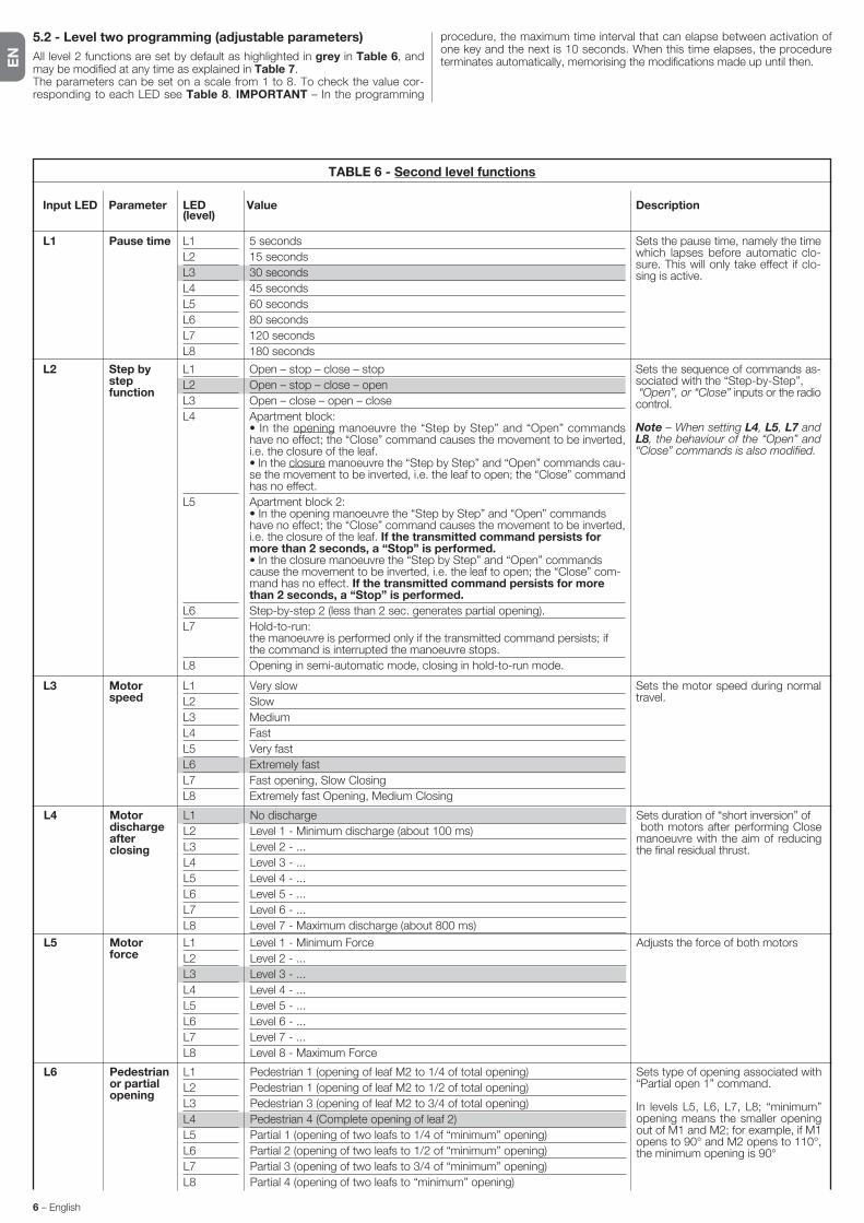
5.2 - Level two programming (adjustable parameters)
All level 2 functions are set by default as highlighted in grey in Table 6, and may be modified at any time as explained in Table 7.The parameters can be set on a scale from 1 to 8. To check the value cor-responding to each LED see Table 8. IMPORTANT – In the programming
procedure, the maximum time interval that can elapse between activation of one key and the next is 10 seconds. When this time elapses, the procedure terminates automatically, memorising the modifications made up until then.
TABLE 6 - Second level functions
Input LED Parameter LED Value Description (level)
L1 L1
L2
L3
L4
L5
L6
L7
L8
5 seconds
15 seconds
30 seconds
45 seconds
60 seconds
80 seconds
120 seconds
180 seconds
Sets the pause time, namely the time which lapses before automatic clo-sure. This will only take effect if clo-sing is active.
Pause time
L2 L1
L2
L3
L4
L5
L6
L7
L8
Open – stop – close – stop
Open – stop – close – open
Open – close – open – close
Apartment block: • In the opening manoeuvre the “Step by Step” and “Open” commands have no effect; the “Close” command causes the movement to be inverted, i.e. the closure of the leaf. • In the closure manoeuvre the “Step by Step” and “Open” commands cau-se the movement to be inverted, i.e. the leaf to open; the “Close” command has no effect.
Apartment block 2: • In the opening manoeuvre the “Step by Step” and “Open” commands have no effect; the “Close” command causes the movement to be inverted, i.e. the closure of the leaf. If the transmitted command persists for more than 2 seconds, a “Stop” is performed. • In the closure manoeuvre the “Step by Step” and “Open” commands cause the movement to be inverted, i.e. the leaf to open; the “Close” com-mand has no effect. If the transmitted command persists for more than 2 seconds, a “Stop” is performed.
Step-by-step 2 (less than 2 sec. generates partial opening).
Hold-to-run: the manoeuvre is performed only if the transmitted command persists; if the command is interrupted the manoeuvre stops.
Opening in semi-automatic mode, closing in hold-to-run mode.
Sets the sequence of commands as-sociated with the “Step-by-Step”, “Open”, or “Close” inputs or the radio control.
Note – When setting L4, L5, L7 and L8, the behaviour of the “Open” and “Close” commands is also modified.
Step by step function
L3 L1
L2
L3
L4
L5
L6
L7
L8
Very slow
Slow
Medium
Fast
Very fast
Extremely fast
Fast opening, Slow Closing
Extremely fast Opening, Medium Closing
Sets the motor speed during normal travel.
Motor speed
L6 L1
L2
L3
L4
L5
L6
L7
L8
Pedestrian 1 (opening of leaf M2 to 1/4 of total opening)
Pedestrian 1 (opening of leaf M2 to 1/2 of total opening)
Pedestrian 3 (opening of leaf M2 to 3/4 of total opening)
Pedestrian 4 (Complete opening of leaf 2)
Partial 1 (opening of two leafs to 1/4 of “minimum” opening)
Partial 2 (opening of two leafs to 1/2 of “minimum” opening)
Partial 3 (opening of two leafs to 3/4 of “minimum” opening)
Partial 4 (opening of two leafs to “minimum” opening)
Sets type of opening associated with “Partial open 1” command.
In levels L5, L6, L7, L8; “minimum” opening means the smaller opening out of M1 and M2; for example, if M1 opens to 90° and M2 opens to 110°, the minimum opening is 90°
Pedestrian or partial opening
L4 L1
L2
L3
L4
L5
L6
L7
L8
No discharge
Level 1 - Minimum discharge (about 100 ms)
Level 2 - ...
Level 3 - ...
Level 4 - ...
Level 5 - ...
Level 6 - ...
Level 7 - Maximum discharge (about 800 ms)
Sets duration of “short inversion” of bo th motors after performing Close ma noeuvre with the aim of reducing the final residual thrust.
Motor discharge after closing
L5 L1
L2
L3
L4
L5
L6
L7
L8
Level 1 - Minimum Force
Level 2 - ...
Level 3 - ...
Level 4 - ...
Level 5 - ...
Level 6 - ...
Level 7 - ...
Level 8 - Maximum Force
Adjusts the force of both motorsMotor force

EN
English – 7
TABLE 7 – Programming procedure (second level functions)
01. Press and hold down the “Set” key for approx. 3 seconds.;
02. Release the key when LED “L1” starts flashing;
03. Press the “ ” or “ ” key to move the flashing LED to the LED representing the “input LED” of the parameter to be modified;
04. Press and hold the “Set” key through to completion of point 06;
05. Wait approx. 3 seconds, until the LED representing the current level of the parameter to be modified illuminates;
06. Press keys “ ” or “ ” to move the LED representing the value of the parameter;
07. Release the “Set” key;
08. Wait 10 seconds (maximum time) to exit the programming mode.
Note – During this procedure, points 03 to 07 need to be repeated when programming other parameters during the phase itself.
SET
SET
SET
SETL1
or
or
3 s
10 s
5.3 - Special functions
5.3.1 - Function: “Move anyway”
This function allows the automation to be operated even when any of the safety devices does not work correctly or is out of use.The automation can be controlled in the “hold-to-run” mode. Proceed as follows:01. Send a command to operate the gate using a transmitter or a key selector,
etc. If everything operates correctly, the gate will move normally, otherwise proceed as follows;
02. within 3 seconds, activate the control again and keep it activated;03. after approximately 2 seconds, the gate will perform the required movement
in “hold-to-run” mode; i.e. the gate will continue to move only as long as the control is activated.
If the safety devices do not operate, the flashing light flashes a few times to indi-cate the kind of problem (see chapter 6 - Table 9).
5.3.2 - Function: “Maintenance warning”
This function serves to indicate when the automation requires maintenance. The maintenance warning signal is given by way of a lamp connected to the S.C.A. (open gate light) output when this output is programmed as “Maintenan-ce light”. The various warning lamp signals are shown in Table 8.
To program the limit value of the maintenance operations, see Table 7.
5.4 - Deleting the memory
To delete the control unit memory and restore all factory settings, proceed as follows: press and hold keys “ ” and “ ” until leds L1 and L2 start flashing.
Table 8 - “Maintenance light”
Number of manoeuvres Signal
Light on for 2 seconds at the start of the opening manoeuvre.
Light flashing for the entire duration of the manoeuvre.
Light flashing continuously.
Below 80% of the limit
Between 81% and 100% of the limit
Beyond 100% of the limit
Note – The factory settings are highlighted in grey.
L8 L1
L2
L3
L4
L5
L6
L7
L8
Manoeuvre 1 result (most recent)
Manoeuvre 2 result
Manoeuvre 3 result
Manoeuvre 4 result
Manoeuvre 5 result
Manoeuvre 6 result
Manoeuvre 7 result
Manoeuvre 8 result
The type of fault that has occurred in the last 8 manoeuvres can be esta-blished
See TABLE 11 – Fault log.
List of faults
L7 L1
L2
L3
L4
L5
L6
L7
L8
500
1000
1500
2500
5000
10000
15000
20000
Controls the number of manoeuvres: when this number is exceeded, the control unit signals an automation maintenance request; see paragraph 5.3.2. – Maintenance warning.
Mainte-nance warning
EN
8 – English
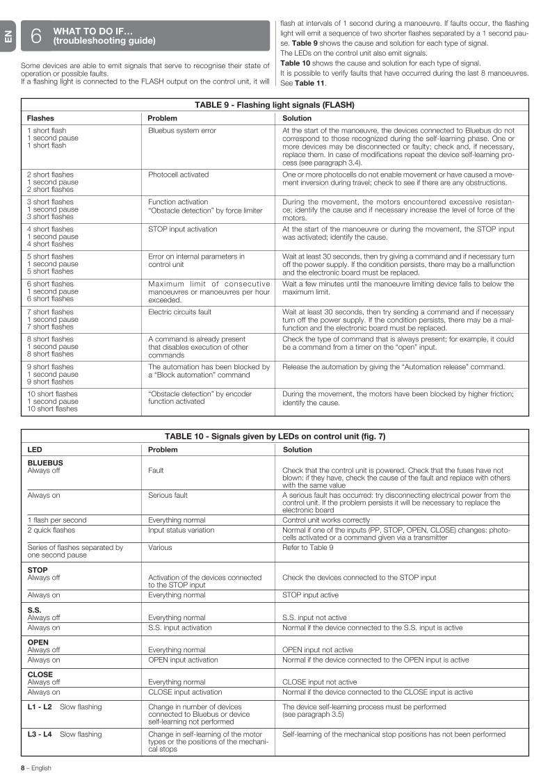
Some devices are able to emit signals that serve to recognise their state of operation or possible faults.If a flashing light is connected to the FLASH output on the control unit, it will
flash at intervals of 1 second during a manoeuvre. If faults occur, the flashing
light will emit a sequence of two shorter flashes separated by a 1 second pau-
se. Table 9 shows the cause and solution for each type of signal.
The LEDs on the control unit also emit signals.
Table 10 shows the cause and solution for each type of signal.
It is possible to verify faults that have occurred during the last 8 manoeuvres.
See Table 11.
WHAT TO DO IF… (troubleshooting guide)6
7 short flashes1 second pause7 short flashes
Electric circuits fault Wait at least 30 seconds, then try sending a command and if necessary turn off the power supply. If the condition persists, there may be a mal-function and the electronic board must be replaced.
8 short flashes1 second pause8 short flashes
A command is already present that disables execution of other commands
Check the type of command that is always present; for example, it could be a command from a timer on the “open” input.
9 short flashes1 second pause9 short flashes
The automation has been blocked by a “Block automation” command
Release the automation by giving the “Automation release” command.
10 short flashes1 second pause10 short flashes
“Obstacle detection” by encoder function activated
During the movement, the motors have been blocked by higher friction; identify the cause.
TABLE 9 - Flashing light signals (FLASH)
Flashes Problem Solution
1 short flash1 second pause1 short flash
Bluebus system error At the start of the manoeuvre, the devices connected to Bluebus do not correspond to those recognized during the self-learning phase. One or more devices may be disconnected or faulty; check and, if necessary, replace them. In case of modifications repeat the device self-learning pro-cess (see paragraph 3.4).
2 short flashes1 second pause2 short flashes
Photocell activated One or more photocells do not enable movement or have caused a move-ment inversion during travel; check to see if there are any obstructions.
3 short flashes1 second pause3 short flashes
Function activation“Obstacle detection” by force limiter
During the movement, the motors encountered excessive resistan-ce; identify the cause and if necessary increase the level of force of the motors.
4 short flashes1 second pause4 short flashes
STOP input activation At the start of the manoeuvre or during the movement, the STOP input was activated; identify the cause.
5 short flashes1 second pause5 short flashes
Error on internal parameters in control unit
Wait at least 30 seconds, then try giving a command and if necessary turn off the power supply. If the condition persists, there may be a malfunction and the electronic board must be replaced.
6 short flashes1 second pause6 short flashes
Maximum l imit of consecut ive manoeuvres or manoeuvres per hour exceeded.
Wait a few minutes until the manoeuvre limiting device falls to below the maximum limit.
TABLE 10 - Signals given by LEDs on control unit (fig. 7)
LED Problem Solution
BLUEBUSAlways off
Always on
1 flash per second
2 quick flashes
Series of flashes separated by one second pause
STOPAlways off
Always on
S.S.Always off
Always on
OPENAlways off
Always on
CLOSEAlways off
Always on
L1 - L2 Slow flashing
L3 - L4 Slow flashing
Fault
Serious fault
Everything normal
Input status variation
Various
Activation of the devices connected to the STOP input
Everything normal
Everything normal
S.S. input activation
Everything normal
OPEN input activation
Everything normal
CLOSE input activation
Change in number of devices connected to Bluebus or device self-learning not performed
Change in self-learning of the motor types or the positions of the mechani-cal stops
Check that the control unit is powered. Check that the fuses have not blown: if they have, check the cause of the fault and replace with others with the same value
A serious fault has occurred: try disconnecting electrical power from the control unit. If the problem persists it will be necessary to replace the electronic board
Control unit works correctly
Normal if one of the inputs (PP, STOP, OPEN, CLOSE) changes: photo-cells activated or a command given via a transmitter
Refer to Table 9
Check the devices connected to the STOP input
STOP input active
S.S. input not active
Normal if the device connected to the S.S. input is active
OPEN input not active
Normal if the device connected to the OPEN input is active
CLOSE input not active
Normal if the device connected to the CLOSE input is active
The device self-learning process must be performed (see paragraph 3.5)
Self-learning of the mechanical stop positions has not been performed

EN
English – 9
3 sSET
SET
SET
SETL1
or
and
3 s
L8
The following optional accessories are available for the control unit MC824HR: SMXI, OXI family receivers, Oview programmer, the Solemyo solar energy panel and the PS324 buffer battery.
7.1 - Connecting a radio receiver
The control unit has a connector for connecting radio receivers (optional accesso-ries) belonging to the SMXI and OXI families. To connect a receiver, disconnect power from the control unit and proceed as shown in fig. 8. Table 12 and Table 13 show the commands corresponding to the outputs on the control unit.
FURTHER DETAILS7
Table 12
SMXI / SMXIS or OXI / OXIFM / OXIT / OXITFM in mode I or Mode II
“S.S.” (Step by Step) command
“Partial opening 1” command
“Open” command
“Close” command
Output no. 1
Output no. 2
Output no. 3
Output no. 4
1 Step by step
2 Partial opening 1
3 Open
4 Close
5 Stop
6 Apartment block Step by Step
7 Step by Step high priority
8 Partial open 2
9 Partial open 3
10 Open and block automation
11 Close and block automation
12 Block automation
13 Release automation
14 Courtesy light timer on
15 Courtesy light on-off
Table 13
OXI / OXIFM /OXIT / OXITFM in extended mode II
No. Command Description
“S.S.” (Step by Step) command
“Partial opening 1” command
“Open” command
“Close” command
Stops manoeuvre
Apartment block control
Gives command even when automation is blocked or commands are in progress
Partial open (Opening of leaf M2 to 1/2 of normal opening)
Partial open (Opening of two leafs to 1/2 of normal opening)
It causes an opening manoeuvre, after which the automa-tion is blocked; the control unit accepts no further com-mands with the exception of “Step by step high priority”, “Release” automation and (from Oview only) the comman-ds “Release and close” and “Release and open”
It causes a closure manoeuvre, after which the automation is blocked; the control unit accepts no further commands with the exception of “Step by step high priority”, “Release” automation and (from Oview only) the commands “Release and close” and “Release and open”
It causes the manoeuvre to stop and the automation to block; the control unit accepts no further commands with the exception of “Step by step high priority”, “Release” au to mation and (from Oview only ) the commands “Relea-se and close” and “Release and open”.
It causes the automation to be released and normal ope-ration to resume
The Courtesy light comes on with timed turning off
The Courtesy light turns on and off in step-by-step mode
7.2 - Connecting Oview programming unit
Connector BusT4 on the control unit enables connection of the programming unit Oview which enables complete and rapid management of installation, maintenance and troubleshooting of any malfunctions of the whole automation system. To gain access to the connector, proceed as shown in fig. 9 and con-nect the connector to its seat. The Oview can be connected simultaneously to a number of control units (up to 5 without any particular precautions, up to 60 following the relevant warnings) and can remain connected to the control unit during normal operation of the automation. In this case a specific “user” menu enables commands to be sent directly to the control unit. It is also possible to update the firmware. If an OXI family radio receiver is present in the control unit, Oview enables access to the parameters of the transmitters memorised in this receiver.Further information is available in the instruction manual and the “Opera system book” manual.
7.3 - Connecting the Solemyo solar energy system
To connect the solar energy system see fig. 10.
IMPORTANT! – When the automation is powered by the “Solemyo” system, it MUST NOT BE POWERED at the same time from the elec-trical mains.
For other information, refer to the relevant instruction manual.
7.4 - Connecting model PS324 buffer battery
To connect the buffer battery, see fig. 10. For other information, refer to the relevant instruction manual.
TABLE 11 - Fault log
01. Press and hold down the “Set” key for approx. 3 seconds;
02. Release the key when LED “L1” starts flashing;
03. Press keys “ ” or “ ” to move from the flashing LED to L8 LED (“input LED”) for the “Fault log” parameter;
04. Press and hold the “Set” key through to completion of point 06;
05. Wait approx. 3 seconds until the LEDs representing the levels corresponding to the manoeuvres with faults illuminate. The LED L1 indicates the result of the most recent manoeuvre while L8 indicates the eighth-to-last manoeuvre.
If the LED is on this means that a fault has occurred; if the LED is off, everything is normal;
06. Press keys “ ” and “ ” to select the required manoeuvre: the corresponding LED performs a number of flashes equal to those normally performed by the flashing light;
07. Release the “Set” key.

EN
10 – English
WARNINGS: • All technical characteristics stated refer to an ambient temperature of 20°C (±5°C). • Nice S.p.a reserves the right to modify the product at any time while maintaining the same functionalities and intended use.
MC824HR power supply 230 Vac (+10% -15%) 50/60 Hz MC824HR/V1 power supply 120 Vac (+10% -15%) 50/60 Hz
Nominal power absorbed from mains 200 W
Power absorbed by control unit battery connector with “standby-All” operation below 100 mW (including a receiver with SM type connector)
Flashing light output [*] 1 “LUCYB” type flashing light (12 V, 21 W lamp)
Electric lock output [*] 1 max. 12 Vac max. 15 VA electric lock
Gate open light output [*] one 24 V max. 4 W lamp (output voltage may vary between -30% and +50%, output may also control small relays)
BLUEBUS output 1 output with maximum load 15 Bluebus units (maximum 6 pairs of MOFB or MOFOB photocells + 2 pairs of MOFB or MOFOB
photocells assigned as Opening devices + max. 4 MOMB or MOTB control devices
STOP Input For normally closed, normally open or 8.2 kΩ constant resistance contacts in self-learning mode (a change from the memorised
state prompts the “STOP” command)
PP Input for normally open contacts (closure of the contact prompts the Step by Step command)
OPEN Input for normally open contacts (closure of the contact prompts the OPEN command)
CLOSE Input for normally open contacts (closure of the contact prompts the CLOSE command)
Radio connector SM connector for SMXI, OXI and OXIFM family receivers
Radio AERIAL input 50 Ω for RG58 or similar type cable
Programmable functions 8 ON-OFF type functions and 8 adjustable functions
• Self-learning of devices connected to the BlueBus outputFunctions in self-learning mode • Self-learning of type of device connected to “STOP” terminal (NO, NC or 8.2 kΩ resistance contact) • Self-learning of leaf travel and automatic calculation of deceleration and partial opening points (vary according to installation)
Operating temperature from - 20 °C a + 50 °C
Use in particularly acid, saline or NO
potentially explosive atmospheres
Protection rating IP 54 with enclosure intact
Dimensions (mm) 310 x 232 x H 122
Weight (kg) 4,1
[*] The Flashing Light, Electric Lock and Gate Open Warning light outputs can be programmed with other functions (see “TABLE 5 - 1st level functions”; or via Oview programmer, see chapter 7.2). The electrical characteristics of the output vary according to programming:
flashing light: 12Vdc, 21 Wmax lamp
electric lock: 12Vac 15 VAmax
other outputs (all types): 1 lamp or relay 24Vdc (-30 and +50%), 4 Wmax
TECHNICAL CHARACTERISTICS OF THE PRODUCT
PRODUCT MAINTENANCE8Regular maintenance is needed to keep the level of safety constant and to ensure the maximum durability of the entire automation.
Maintenance must be performed in strict accordance with the safety provisions set out in this manual and with the requirements of applicable laws and stan-dards.
Important – During maintenance and cleaning the control unit must be discon-nected from the electrical power supply.
For devices other than the MC824HR follow the instructions given in the rele-vant maintenance programmes.
For the MC824HR scheduled maintenance must be performed no more than 6 months or 20,000 manoeuvres after previous maintenance.
To perform maintenance, proceed as follows:01. Disconnect all electric power sources, including any buffer batteries;02. Check all materials making up the control unit for wear, with particular
attention to erosion or oxidation of parts; replace parts that are not in opti-mal condition;
03. Reconnect the power supply and perform the checks described in chapter 4.1 - Testing.
PRODUCT DISPOSAL
This product is an integral part of the automation system it controls and must be disposed of along with it.As in the case of installation, likewise at the end of product lifetime the disas-sembly and scrapping operations must be performed by qualified personnel.This product is made of various types of material, some of which can be recycled while others must be scrapped. Seek information on the recycling and disposal methods envisaged by the local regulations in your area for this product category.Important! – Some parts of the product may contain polluting or hazardous substances which, if released to the environment, may cause serious damage to the environment or to human health.As indicated by the symbol alongside, disposal of this product with domestic waste is strictly prohibited. Separate the waste into categories for disposal, according to the methods established by current legislation in your area, or return the product to the retailer when purchasing a new version.Important! – Local legislation may impose heavy fines in the event of illegal disposal of this product.
Disposal of buffer battery (if present)
Important! – Even if discharged, the batteries may contain pollutant sub-stances and therefore must NEVER be disposed of in normal waste collection points.
Dispose of according to separate waste collection methods as envisaged by current local standards.

IT
Italiano – 1
ITALIANO
SommarioAVVERTENZE E PRECAUZIONI GENERALI . . . . . . . . . . . . . . . . . . . . . . 1Avvertenze per la sicurezza . . . . . . . . . . . . . . . . . . . . . . . . . . . . . . . . . . . . . . 1Avvertenze per l’installazione . . . . . . . . . . . . . . . . . . . . . . . . . . . . . . . . . . . . 1Avvertenze per l’uso . . . . . . . . . . . . . . . . . . . . . . . . . . . . . . . . . . . . . . . . . . . 1
1 - DESCRIZIONE DEL PRODOTTO E DESTINAZIONE D’USO . . . . . . . 1
2 - INSTALLAZIONE . . . . . . . . . . . . . . . . . . . . . . . . . . . . . . . . . . . . . . . . . 12.1 - Verifiche preliminari all’installazione . . . . . . . . . . . . . . . . . . . . . . . . . . . . 12.2 - Limiti d’impiego del prodotto . . . . . . . . . . . . . . . . . . . . . . . . . . . . . . . . 22.3 - Impianto tipico . . . . . . . . . . . . . . . . . . . . . . . . . . . . . . . . . . . . . . . . . . . 22.4 - Installazione della centrale di comando . . . . . . . . . . . . . . . . . . . . . . . . . 2
3 - COLLEGAMENTI ELETTRICI . . . . . . . . . . . . . . . . . . . . . . . . . . . . . . . . 23.1 - Descrizione dei collegamenti elettrici . . . . . . . . . . . . . . . . . . . . . . . . . . 23.2 - Collegamenti elettrici della centrale MC824HR . . . . . . . . . . . . . . . . . . . 23.3 - Collegamento di altri dispositivi a MC824HR . . . . . . . . . . . . . . . . . . . . 33.4 - Indirizzamento dei dispositivi collegati a MC824HR . . . . . . . . . . . . . . . 33.5 - Prima accensione e verifica dei collegamenti . . . . . . . . . . . . . . . . . . . . 33.6 - Apprendimento dei dispositivi collegati a MC824HR . . . . . . . . . . . . . . . 33.7 - Apprendimento delle posizioni dei finecorsa meccanici . . . . . . . . . . . . . 3 3.7.1 - Apprendimento in modo automatico . . . . . . . . . . . . . . . . . . . . . 3 3.7.2 - Apprendimento in modo manuale . . . . . . . . . . . . . . . . . . . . . . . 4 3.7.3 - Apprendimento in modo misto . . . . . . . . . . . . . . . . . . . . . . . . . 43.8 - Verifica del movimento delle ante del cancello . . . . . . . . . . . . . . . . . . . 4
4 - COLLAUDO E MESSA IN SERVIZIO . . . . . . . . . . . . . . . . . . . . . . . . . . 44.1 - Collaudo. . . . . . . . . . . . . . . . . . . . . . . . . . . . . . . . . . . . . . . . . . . . . . . . 44.2 - Messa in servizio . . . . . . . . . . . . . . . . . . . . . . . . . . . . . . . . . . . . . . . . . 5
5 - PROGRAMMAZIONE . . . . . . . . . . . . . . . . . . . . . . . . . . . . . . . . . . . . . . 55.1 - Programmazione primo livello (ON-OFF) . . . . . . . . . . . . . . . . . . . . . . . . 55.2 - Programmazione secondo livello (parametri regolabili) . . . . . . . . . . . . . 65.3 - Funzioni speciali . . . . . . . . . . . . . . . . . . . . . . . . . . . . . . . . . . . . . . . . . . 75.4 - Cancellazione della memoria . . . . . . . . . . . . . . . . . . . . . . . . . . . . . . . . 7
6 - COSA FARE SE... (guida alla risoluzione dei problemi) . . . . . . . . . . 8
7 - APPROFONDIMENTI . . . . . . . . . . . . . . . . . . . . . . . . . . . . . . . . . . . . . . 97.1 - Collegamento di un ricevitore radio . . . . . . . . . . . . . . . . . . . . . . . . . . . . 97.2 - Collegamento del programmatore Oview . . . . . . . . . . . . . . . . . . . . . . . 97.3 - Collegamento del sistema ad energia solare Solemyo . . . . . . . . . . . . . 97.4 - Collegamento della batteria tampone mod. PS324 . . . . . . . . . . . . . . . . 9
8 - MANUTENZIONE DEL PRODOTTO . . . . . . . . . . . . . . . . . . . . . . . . . 10
SMALTIMENTO DEL PRODOTTO . . . . . . . . . . . . . . . . . . . . . . . . . . . . . 10
CARATTERISTICHE TECNICHE DEL PRODOTTO . . . . . . . . . . . . . . . . 10
DICHIARAZIONE CE DI CONFORMITÀ . . . . . . . . . . . . . . . . . . . . . . . . . . . I
Istruzioni ed avvertenze destinate all’utilizzatore . . . . . . . . . . . . . . . . . VIImmagini . . . . . . . . . . . . . . . . . . . . . . . . . . . . . . . . . . . . . . . . . . . . . . . . . . XII
MC824HR è una centrale elettronica per l’automatizzazione di cancelli ad ante battenti con motori serie Toona modello 5624I (vedere paragrafo “2.2 Limiti di impiego del prodotto). AT TENZIONE! – Qualsiasi altro uso diverso da quello descritto e in condizioni am bientali diverse da quelle riportate in questo manuale è da considerarsi improprio e vietato!La centrale di comando è particolarmente predisposta per essere collegata a dispositivi appartenenti al Sistema Opera, al sistema Bluebus e al sistema di alimentazione ad energia solare Solemyo. Se alimentata da rete, può ospi-tare una batteria tampone (mod. PS324, accessorio opzionale) che nel caso di mancanza dell’energia elettrica (black-out elettrico) garantisce all’automatismo di eseguire, nelle ore successive, alcune manovre. Altri accessori disponibili sono i ricevitori predisposti con innesto “SM” (SMXI, OXI, ecc.).
DESCRIZIONE DEL PRODOTTO E DESTINAZIONE D’USO1
AVVERTENZE E PRECAUZIONI GENERALI
Avvertenze per la sicurezza• ATTENZIONE! – Il presente manuale contiene importanti istruzioni e
avvertenze per la sicurezza delle persone. Un’installazione errata può causare gravi ferite. Prima di iniziare il lavoro è necessario leggere attenta-mente tutte le parti del manuale. In caso di dubbi, sospendere l’installazione e richiedere chiarimenti al Servizio Assistenza Nice.
• ATTENZIONE! – Istruzioni importanti: conservare questo manuale per eventuali interventi futuri di manutenzione e di smaltimento del prodotto.
• ATTENZIONE! – Secondo la più recente legislazione europea, la rea-lizzazione di una porta o di un cancello automatico deve rispettare le norme previste dalla Direttiva 2006/42/CE (ex 98/37/CE) (Direttiva Mac-chine) e in particolare, le norme EN 12445; EN 12453; EN 12635 e EN 13241-1, che consentono di dichiarare la conformità dell’automazione. In considerazione di ciò, tutte le operazioni di installazione, di colle-gamento, di col laudo e di manutenzione del prodotto devono es sere effettuate es clusivamente da un tecnico qualificato e competente!
Avvertenze per l’installazione• Prima di iniziare l’installazione verificare se il presente prodotto è adatto al tipo
di utilizzo desiderato (vedere i “Limiti d’impiego” paragrafo 2.2 e le “Caratteristi-che tecniche del prodotto”). Se non è adatto, NON procedere all’istallazione.
• Il contenuto del presente manuale è riferito ad un impianto tipico come quello descritto in fig. 2a.
• Tutte le operazioni di installazione e di manutenzione devono avve-nire con l’automazione scollegata dall’alimentazione elettrica. Se il dispositivo di sconnessione dell’alimentazione non è visibile dal luogo dove è posizionato l’automatismo, prima di iniziare il lavoro è necessario attacca-re sul di spositivo di sconnessione un cartello con la scritta “ATTENZIONE! MANUTENZIONE IN CORSO”.
• Prevedere nella rete di alimentazione dell’impianto un dispositivo di discon-nessione con una distanza di apertura dei contatti che consenta la disconnes-sione completa nelle condizioni dettate dalla categoria di sovratensione III.
• La centrale deve essere collegata ad una linea di alimentazione elettrica dot-ata di messa a terra di sicurezza.
• Durante l’installazione maneggiare con cura il prodotto evitando schiaccia-menti, urti, cadute o contatto con liquidi di qualsiasi natura. Non mettere il pro dotto vicino a fonti di calore, né esporlo a fiamme libere. Tutte queste azi-oni possono danneggiarlo ed essere causa di malfunzionamenti o situazioni di pericolo. Se questo accade, sospendere immediatamente l’installazione e rivolgersi al Servizio Assistenza Nice.
• Non eseguire modifiche su nessuna parte del prodotto. Operazioni non per-messe possono causare solo malfunzionamenti. Il costruttore declina ogni responsabilità per danni derivanti da modifiche arbitrarie al prodotto.
• Il materiale dell’imballo del prodotto deve essere smaltito nel pieno rispetto della normativa locale.
Avvertenze per l’uso• Il prodotto non è destinato ad essere usato da persone (bambini compresi) le
cui capacità fisiche, sensoriali o mentali siano ridotte, oppure con mancanza di esperienza o di conoscenza, a meno che esse abbiano potuto beneficiare, attraverso l’intermediazione di una persona responsabile della loro sicurezza, di una sorveglianza o di istruzioni riguardanti l’uso del prodotto.
• I bambini che si trovano in prossimità dell’automazione, devono essere sor-vegliati per verificare che non giochino con quest’ultima.
• Non permettere ai bambini di giocare con i dispositivi di comando fissi. Tene-re i dispositivi di comando portatili (remoti) fuori dalla portata dei bambini.
2.1 - Verifiche preliminari all’installazione
Prima di procedere all’installazione, è necessario verificare l’integrità dei com-ponenti del prodotto, l’adeguatezza del modello scelto e l’idoneità dell’ambien-te destinato all’installazione:• Verificare che tutto il materiale da utilizzare sia in ottimo stato e adatto all’uso
previsto.• Verificare che tutte le condizioni di utilizzo rientrino nei limiti d’impiego del
prodotto (paragrafo 2.2) e nei limiti dei valori riportati nelle “Caratteristiche tecniche del prodotto”.
INSTALLAZIONE2

IT
2 – Italiano
COLLEGAMENTI ELETTRICI3Il collegamento elettrico dei vari dispositivi (fotocellule, tastiere digitali, lettori di tessere a transponder, ecc.) presenti nell’automazione con la centrale di co mando, deve essere effettuato tramite il sistema “Bluebus” di Nice.
3.1 - Descrizione dei collegamenti elettrici (fig. 6)
ANTENNA ingresso per l’antenna di un ricevitore radio
FLASH uscita per 1 lampeggiante con lampada da 12 V (massimo 21 W). [*]
ELS uscita per elettroserratura da 12 Vac (massimo 15 VA). [*]
S.C.A. “Spia Cancello Aperto”: uscita per 1 lampada di segnalazione da 24 V e massimo 4 W. [*]
BLUEBUS ingresso per dispositivi compatibili (MOFB, MOFOB, MOB e MOTB; collegamento dei dispositivi in parallelo tramite 2 conduttori nel quale transita sia l’alimentazione elettrica sia i segnali di comu-nicazione; nessuna polarità da rispettare. Il collegamento elettrico da utilizzare è di tipo parallelo e non necessita di rispettare alcuna polarità. Durante la fase di apprendimento, ogni dispositivo col-legato alla centrale verrà riconosciuto singolarmente da questa, grazie ad un codice univoco. Ogni volta che verrà aggiunto o eli-minato un dispositivo, sarà necessario eseguire l’apprendimento di questo da parte della centrale (vedere paragrafo 3.6).
STOP ingresso per dispositivi che con il loro intervento provocano l’arre-sto immediato della manovra in atto, seguito da una breve inver-sione; possibilità di collegare contatti di tipo NA, NC oppure dispo-sitivi con uscita a resistenza costante 8,2 kΩ (bordi sensibili). Ogni dispositivo collegato a questo ingresso, viene riconosciuto singo-larmente dalla centrale durante la fase di apprendimento (paragra-fo 3.6); in questa fase, se la centrale rileva una qualsiasi variazione rispetto allo stato appreso, provoca uno STOP. È possibile colle-gare a questo ingresso uno o più dispositivi anche diversi tra loro:
– collegare in parallelo più dispositivi NA, senza limiti di quantità; – collegare in serie più dispositivi NC, senza limiti di quantità;
Collegamento Tipo di cavo Lunghezza massima consentita
A: Cavo ALIMENTAZIONE CENTRALE DI COMANDO 1 cavo 3 x 1,5 mm2 30 m (nota 1)
B: Cavo LAMPEGGIANTE con antenna 1 cavo 2 x 0,5 mm2 20 m 1 cavo schermato tipo RG58 20 m (consigliato minore di 5 m)
C: Cavo DISPOSITIVI BLUEBUS 1 cavo 2 x 0,5 mm2 20 m (nota 2)
D: Cavo SELETTORE A CHIAVE 2 cavi 2 x 0,5 mm2 (nota 3) 50 m
E: Cavo ALIMENTAZIONE MOTORIDUTTORE 1 cavo 3 x 1,5 mm2 (nota 4) 10 m
F: Cavo COLLEGAMENTO ENCODER 1 cavo 2 x 1 mm2 (nota 4) 10 m
G: Cavo COLLEGAMENTO ELETTROSERRATURA 1 cavo 2 x 1 mm2 10 m
Nota 1 – Se il cavo di alimentazione supera i 30 m di lunghezza, occorre utilizzare un cavo con sezione maggiore (3 x 2,5 mm2) ed è necessario installare una messa a terra di sicurezza in prossimità dell’automazione.Nota 2 – Se il cavo Bluebus supera i 20 m di lunghezza, fino ad un massimo di 40 m, occorre utilizzare un cavo con sezione maggiore (2 x 1 mm2).Nota 3 – Questi 2 cavi possono essere sostituiti da 1 unico cavo da 4 x 0,5 mm2.Nota 4 – Questi cavi possono essere sostituiti con 1 unico cavo da 5 x 1,5 mm2.
ATTENZIONE! – I cavi utilizzati devono essere adatti al tipo di ambiente in cui avviene l’installazione.
TABELLA 1 - Caratteristiche tecniche dei cavi elettrici (fig. 2b)
– collegare in parallelo 2 dispositivi con uscita a resistenza costan-te 8,2 kΩ. Se sono più di 2 i dispositivi è necessario collegarli a cascata con 1 sola resistenza di terminazione da 8,2 kΩ;
– collegare in parallelo 2 dispositivi NA e NC, mettendo in serie al contatto NC una resistenza da 8,2 kΩ (questo rende possibile anche la combinazione tra 3 dispositivi NA - NC e 8,2 kΩ)
P.P. ingresso per dispositivi di comando che intervenendo, provocano la manovra con modalità Passo Passo; possibilità di collegare contatti di tipo NA
OPEN ingresso per dispositivi di comando che intervenendo, provocano solo la manovra di apertura; possibilità di collegare contatti di tipo NA
CLOSE ingresso per dispositivi di comando che intervenendo, provocano solo la manovra di Chiusura possibilità di collegare contatti di tipo NA
ENC1 ingresso encoder - motoriduttore 1 (morsetto 1, 2); nessuna polarità da rispettare
ENC2 ingresso encoder - motoriduttore 2 (morsetto 4, 5); nessuna polarità da rispettare
M1 uscita per motoriduttore 1 (morsetto 7, 8, 9)
M2 uscita per motoriduttore 2 (morsetto 10, 11, 12).
[*] Le uscite FLASH, ELS e S.C.A. possono essere programmate con altre fun-zioni (vedere “TABELLA 4 - Funzioni 1° livello”; oppure tramite programmatore Oview, vedere capitolo 7.2).
3.2 - Collegamenti elettrici della centrale MC824HR
Dopo aver fissato il box della centrale e predisposto i fori per il passaggio dei cavi eletrtrici (cap. 2.4 e fig. 3), effettuare i collegamenti elettrici:
ATTENZIONE!– Tutti i collegamenti elettrici devono essere eseguiti in assenza di ali-mentazione elettrica di rete e con la batteria tampone scollegata, se presente nell’automazione.– Le operazioni di collegamento devono es sere eseguite esclusivamen-te da personale qualificato.– Sulla linea elettrica di alimentazione, è necessario prevedere un dispositivo che assicuri la disconnessione completa dell’automazione dalla rete. Il dispo-sitivo di disconnessione deve avere i contatti con distanza di apertura tale da
• Verificare che l’ambiente scelto per l’installazione sia compatibile con l’in-gombro totale del prodotto (vedere fig. 1).
• Verificare che la superficie scelta per l’installazione del prodotto sia solida e possa garantire un fissaggio stabile.
• Verificare che la zona di fissaggio non sia soggetta ad allagamenti; eventual-mente prevedere il montaggio del prodotto adeguatamente sollevato da terra.
• Verificare che lo spazio intorno al prodotto consenta un accesso facile e sicuro.• Verificare che tutti i cavi elettrici da utilizzare siano del tipo elencato nella
Tabella 1.• Verificare che nell’automazione siano presenti gli arresti meccanici sia in chiu-
sura sia in apertura.
2.2 - Limiti d’impiego del prodotto
La centrale MC824HR può essere utilizzata esclusivamente con i motoridut-tori Toona mod. 5624I; questi motori, sono reversibili: cioè, è possibile muo-vere manualmente le ante del cancello senza dover sbloccare manualmente il motoriduttore. Grazie ad un sensore inserito nel motore, la centrale è in grado di rilevare il movimento manuale delle ante ed inoltre, gestire correttamente le manovre successive; questo, serve per evitare che le ante vadano a sbattere contro i fermi meccanici di apertura e chiusura. Attenzione! - Se la centrale non è alimentata correttamente oppure se è attiva la funzione “stand By tutto”, il movimento manuale delle ante non viene rilevato.
2.3 - Impianto tipico
La fig. 2a mostra un esempio di impianto di automatizzazione, realizzato con componenti Nice:a - Centrale di comandob - Motoriduttorec - Segnalatore lampeggianted - Fotocellula
e - Tastiera digitale - Lettore a transponder - Selettore a chiavef - Colonna per fotocellulag - Arresti meccanici in aperturah - Arresto meccanico in chiusurai - Elettroserratura
Questi componenti sono posizionati se condo uno schema tipico e usuale. Facendo riferimento alla fig. 2a, stabilire la posizione approssimativa in cui ver-rà installato ciascun componente previsto nell’impianto. Importante – Prima di eseguire l’installazione, preparare i cavi elettrici necessari al vostro impianto, facendo riferimento alla fig. 2b e alla “Tabella 1 - Caratteristiche tecniche dei cavi elettrici”. Attenzione – Durante la posa in opera dei tubi per il pas-saggio dei cavi elettrici e l’entrata dei cavi nel contenitore della centrale, consi-derare che a causa di possibili depositi d’acqua presenti nei pozzetti di deriva-zione, i tubi di collegamento possono creare fenomeni di condensa all’interno della centrale che possono danneggiare i circuiti elettronici.
2.4 - Installazione della centrale di comando
Per eseguire il fissaggio della centrale di comando, procedere come mostrato nella fig. 3:01. Aprire il box della centrale svitando le apposite viti (fig. 3-A);02. Predisporre i fori per il passaggio dei cavi elettrici (fig. 3-B);03. Fissare il box (fig. 3-C);04. A questo punto è possibile effettuare i collegamenti elettrici: vedere cap. 3.Attenzione! – Per predisporre l’ingresso dei tubi per i cavi elettrici, occorre forare il lato inferiore del box della centrale. Nota – Se necessario, è possibile utilizzare l’entrata cavi laterale, ma solo con l’uso di idonei raccordi per tubi.Per eseguire l’installazione degli altri dispositivi presenti nell’automazione, fare riferimento ai rispettivi manuali d’istruzioni.

IT
Italiano – 3
consentire la disconnessione completa, nelle condizioni sancite dalla cate-goria di sovratensione III, conformemente alle regole di installazione. In caso di necessità, questo dispositivo garantisce una veloce e sicura sconnessione dell’alimentazione; pertanto deve essere posizionato in vista dell’automazione. Se invece è collocato in posizione non visibile, deve avere un sistema che bloc-ca un’eventuale riconnessione accidentale o non autorizzata dell’alimentazio-ne, al fine di scongiurare qualsiasi pericolo. Il dispositivo di sconnessione non è fornito con il prodotto.
01. Collegare prima il cavo di alimentazione elettrica (fig. 4) e bloccarlo con il pressa-cavo;
02. Ora collegare i cavi elettrici dei motori M1 e M2, rispettando i simboli sull’e-tichetta (fig. 5):
a) collegare al morsetto M1 il motore che aziona l’anta inferiore (la seconda che inizia la manovra di apertura) e poi, il rispettivo encoder ai morsetti 1-2;
b) collegare al morsetto M2 il motore che aziona l’anta superiore (la prima che inizia la manovra di apertura) e poi, il rispettivo encoder ai morsetti 4-5
IMPORTANTE! – Se nell’impianto è presente un solo motoriduttore, collegarlo al morsetto M2 lasciando libero il morsetto M1;
03. Ora, collegare i cavi elettrici dei vari dispositivi presenti facendo riferimento alla fig. 6 e vedere paragrafo 3.3. Nota – Per facilitare i collegamenti dei cavi, è possibile estrarre i morsetti dalle proprie sedi.
3.3 - Collegamento di altri dispositivi a MC824HR
Se si necessita di alimentare ulteriori dispositivi previsti nell’impianto, ad esem-pio un lettore di tessere a transponder oppure la luce d’illuminazione per il selet-tore a chiave, è possibile collegare questi dispositivi alla centrale di comando sui morsetti “P.P. (positivo)” e “STOP (negativo)” (fig. 6). La tensione di alimen-tazione è 24 Vcc (-30% ÷ +50%) con corrente massima disponibile di 200 mA.Nota – La tensione disponibile nei morsetti “P.P.” e “STOP”, rimane presente anche quando viene attivata la funzione “Stand By” sulla scheda.
3.4 - Indirizzamento dei dispositivi collegati a MC824HR
Per permettere alla centrale di riconoscere i dispositivi collegati al sistema Blue-bus, è necessario eseguire l’indirizzamento di quest’ultimi. Questa operazione deve essere eseguita posizionando correttamente il ponticello elettrico presen-te in ogni dispositivo, vedere il manuale istruzioni di ogni singolo dispositivo: vedere fig. A e Tabella 2.Alla fine della procedura d’installazione oppure in seguito alla rimozione di foto-cellule o di altri dispositivi, è necessario eseguire la procedura di apprendimen-to di quest’ultimi; vedere il paragrafo 3.6.
3.5 - Prima accensione e verifica dei collegamenti
Dopo aver dato alimentazione elettrica alla centrale di comando, eseguire le seguenti verifiche:• trascorsi alcuni secondi, verificare che il Led “Bluebus” (fig. 7) lampeggi rego-
larmente con frequenza di 1 lampeggio al secondo;
• verificare che i Led delle fotocellule (fig. 7), sia TX sia RX, emettano lampeggi. Il tipo di lampeggio emesso, in questa fase, non è significativo;
• verificare che il lampeggiante collegato all’uscita FLASH sia spento.Se tutto questo non avviene, è necessario togliere l’alimentazione elettrica alla centrale e controllare i vari collegamenti elettrici precedentemente effettuati.
3.6 - Apprendimento dei dispositivi collegati a MC824HR
Dopo aver effettuato la prima accensione, è necessario far riconoscere alla centrale i dispositivi collegati agli ingressi “Bluebus” e “Stop”.ATTENZIONE! – La fase di apprendimento deve essere eseguita anche se alla centrale non è collegato alcun dispositivo.La centrale, è in grado di riconoscere singolarmente i vari dispositivi collegati grazie alla procedura di apprendimento e di rilevare le possibili anomalie pre-senti. Per questo, è necessario eseguire l’apprendimento dei dispositivi ogni volta che uno di questi viene aggiunto oppure viene rimosso.I Led “L1” e “L2” presenti sulla centrale (fig. 7), emettono dei lampeggi lenti per indicare che è necessario eseguire l’apprendimento:01. Premere e tenere premuti contemporaneamente i tasti “ ” e “Set” (fig. 7).02. Rilasciare i tasti quando i led “L1” e “L2” iniziano a lampeggiare veloce-
mente (dopo circa 3 secondi).03. Attendere alcuni secondi che la centrale completi la fase di apprendimento
dei dispositivi.04. Al termine di questa fase il Led “Stop” deve essere acceso e i Led “L1” e “L2”
si devono spegnere (potrebbero iniziare a lampeggiare i Led “L3” e “L4”).
3.7 - Apprendimento delle posizioni dei finecorsa meccanici
Dopo l’apprendimento dei dispositivi collegati (paragrafo 3.6), è necessario ese-guire l’apprendimento delle posizioni degli arresti meccanici (massima apertura e massima chiusura). Questa procedura può essere eseguita in tre mo dalità: automatico, manuale e misto.Nel modo automatico, la centrale esegue l’apprendimento degli arresti mecca-nici e calcola gli sfasamenti più opportuni delle ante (SA e SC, fig. B).Nel modo manuale, le otto posizioni degli arresti meccanici (fig. B) sono pro-grammate una ad una, spostando le ante nei punti desiderati. La posizione da programmare è individuabile grazie al lampeggio di uno degli 8 led (L1...L8), vedere Tabella 3.Nel modo misto, è possibile eseguire la procedura automatica e poi, con la procedura manuale, modificare una o più posizioni ad eccezione delle posizioni “0” e “1” (fig. B) che coincidono con le posizioni dei fermi meccanici.
3.7.1 - Apprendimento in modo automatico
01. Premere e tenere premuti contemporaneamente i tasti “Set” e “ ”;
02. Quando i led “L3” e “L4” iniziano a lampeggiare velocemente, (dopo circa 3 sec.) rilasciare i tasti;
03. Verificare che l’automatismo esegua le seguenti sequenze di manovre: a - Chiusura lenta del motoriduttore M1 fino all’arresto meccanico b - Chiusura lenta del motoriduttore M2 fino all’arresto meccanico
A
TABELLA 2 - INDIRIZZI DELLE FOTOCELLULE
Fotocellula Ponticelli
FOTO Fotocellula esterna h = 50 con intervento in chiusura (ferma ed inverte il movimento)
FOTO II Fotocellula esterna h = 100 con intervento in chiusura (ferma ed inverte il movimento)
FOTO 1 Fotocellula interna h = 50 con intervento sia in chiusura (ferma ed inverte il movimento) che in apertura (ferma e riparte al disimpegno della fotocellula)
FOTO 1 II Fotocellula interna h = 100 con intervento sia in chiusura (ferma ed inverte il movimento) che in apertura (ferma e riparte al disimpegno della fotocellula)
FOTO 2 Fotocellula interna con intervento in apertura (ferma ed inverte il movimento)
FOTO 2 II Fotocellula interna con intervento in apertura (ferma ed inverte il movimento)
FOTO 3 CONFIGURAZIONE NON PERMESSA
TABELLA 3
Posizione Led Descrizione
Posizione 0(motore 1)
Posizione 0(motore 2)
Posizione SA(motore 2)
Posizione A(motore 1)
Posizione A(motore 2)
Posizione SC(motore 1)
Posizione 1(motore 1)
Posizione 1(motore 2)
Posizione di massima chiusura: quando l’anta 1 batte sull’ar-resto meccanico di chiusura
Posizione di massima chiusura: quando l’anta 2 batte sull’ar-resto meccanico di chiusura
Sfasamento in apertura: quando l’anta 2 supera questa posi-zione, inizia l’apertura dell’anta 1
Posizione di apertura desiderata: posizione in cui l’anta col-legata al motore 1 deve fermarsi al termine di una ma novra di apertura. Non è necessario che questa posizione coincida con il fermo meccanico di apertura, può essere scelta a piace-re tra la posizione “0” e “1”
Posizione di apertura desiderata: posizione in cui l’anta col-legata al motore 2 deve fermarsi al termine di una ma novra di apertura. Non è necessario che questa posizione coincida con il fermo meccanico di apertura, può essere scelta a piace-re tra la posizione “0” e “1”
Sfasamento in chiusura: quando l’anta 1 si trova al di sotto di questa posizione, inizia la chiusura dell’anta 2
Posizione di massima apertura: quando l’anta 1 batte sull’ar-resto meccanico di apertura
Posizione di massima apertura: quando l’anta 2 batte sull’ar-resto meccanico di apertura
L1
L2
L3
L4
L5
L6
L7
L8
0
1 1A
SC
SA
A
0M1 M2
B POSIZIONI

IT
4 – Italiano
Per comandare e portare il motore 2 nella posizione 1 (fig. B): premere e tenere premuto il tasto “ ” o “ ”. Raggiunta la posizione, rilasciare il tasto per fermare la manovra. Per memorizzare la posizione, premere e tenere premuto il tasto “Set” per almeno 3 sec. e poi rilasciarlo per uscire dalla programmazione (dopo 2 sec. il led L8 rimane acceso fino al rilascio del tasto “Set”).
Nota – Programmazione manuale di un impianto con un solo motori-duttore: procedere come descritto all’inizio di questo paragrafo dal passo 01 al passo 03 procedere come segue:- programmare le posizioni relative ai led L1 (0 di M1) e L7 (1 di M1) nel
modo seguente: mantenere premuto il tasto “Set” per almeno 3 sec. e poi rilasciarlo (dopo 2 sec. il led rimane acceso e al rilascio del tasto “Set” inizia a lampeggiare il led successivo).
- non programmare le posizioni relative ai led L3 (SA di M2) - L4 (A di M1) - L6 (SC di M1)
- per spostarsi tra le posizioni premere brevemente il tasto o .
3.7.3 - Apprendimento in modo misto
Eseguire questa procedura dopo l’esecuzione dell’apprendimento in modo automatico:
01. Premere e tenere premuti contemporaneamente i tasti “Set” e “ ”;02. Rilasciare i tasti quando il led “L1” inizia a lampeggiare (dopo circa 1 secon-
do); Nota – Superati i 3 secondi, se i tasti “Set” e “ ” non vengono rilasciati, si attiva la procedura di “apprendimento automatico” e non quello manuale.
03. Con una breve pressione del tasto “ ” o “ ” spostare il led lampeggiante (L1…L8) sulla posizione che si desidera programmare e procedere per ogni singola posizione, come descritto al passo 03 dell’apprendimento in modo manuale (paragrafo 3.7.2).
Ripetere quest’ultima operazione per tutte le altre posizioni che si desidera modificare.
Per terminare l’apprendimento manuale, premere ripetutamente il tasto “ ”, per spostare il led che lampeggia, oltre la posizione L8.
3.8 - Verifica del movimento delle ante del cancello
Al termine della fase di apprendimento, si consiglia di far eseguire alla centrale alcune manovre di apertura e Chiusura, in modo da verificare il corretto movi-mento del cancello, gli eventuali difetti di montaggio e di regolazione.
01. Premere il tasto “Open”. Verificare il corretto sfasamento delle ante in apertura e verificare che durante la manovra di apertura sia presente la fase di accelerazione, la fase a velocità costante, la fase di rallentamen-to. Terminata la manovra, le ante devono fermarsi a qualche centimetro dall’arresto meccanico di apertura;
02. Premere il tasto “Close” e verificare che durante la manovra di Chiusura sia presente la fase di accelerazione, la fase a velocità costante, la fase di rallentamento. Verificare il corretto sfasamento delle ante in chiusura. Al termine le ante devono essere perfettamente chiuse sull’arresto meccani-co di chiusura;
03. Verificare, durante le manovre, che il lampeggiante esegua lampeggi con intervalli di 0,5 secondi a lampeggiante acceso e di 0,5 secondi a lampeg-giante spento.
c - apertura lenta del motoriduttore M2 e del motoriduttore M1 fino all’ar-resto meccanico
d - Chiusura veloce dei motoriduttori M1 e M2
Avvertenze:– Se la prima manovra (a) non chiude l’anta comandata dal motore M1 ma quella
comandata da M2, premere il tasto “ ” oppure “ ” per fermare la fase di apprendimento. A questo punto, invertire i collegamenti dei motori M1 e M2 sui morsetti presenti sulla centrale e poi, quelli dei rispettivi encoder; infine, iniziare la procedura dal punto 01;
– Se le prime due manovre (a e b) non risultano come “chiusure” ma come “aperture”, premere il tasto “ ” oppure “ ” per fermare la fase di appren-dimento. A questo punto, sul motoriduttore che ha eseguito la manovra di apertura, invertire le polarità dei due fili del motoriduttore M1 (morsetti 7 e 9) e di M2 (morsetti 10 e 12) e poi, iniziare la procedura dal punto 01;
04. Al termine della manovra di Chiusura dei 2 motori (d), i led “L3” e “L4” si spengono ad indicare che la procedura è stata eseguita correttamente.
Avvertenze:– Se durante la procedura di apprendimento automatico, si verifica l’intervento
delle fotocellule oppure di un dispositivo collegato all’ingresso “stop”, la proce-dura si interrompe e il led L1 inizia a lampeggiare. Per riattivare l’apprendimen-to, è necessario riprendere la procedura dal punto 01;
– La procedura di apprendimento automatico, può essere eseguita nuova-mente in qualsiasi momento, anche dopo aver effettuato l’installazione; ad esempio, a seguito della variazione della posizione degli arresti meccanici.
3.7.2 - Apprendimento in modo manuale
Attenzione! – Dal passo 03 in poi:– per spostarsi dal led L1 a L8, occorre una breve pressione del tasto oppu-
re (il led lampeggia, indicando l’attuale posizione);– per far muovere il motore in un senso o nell’altro, occorre la pressione conti-
nua del tasto oppure .
01. Premere e tenere premuti contemporaneamente i tasti “Set” e “ ”;
02. Rilasciare i tasti quando il led “L1” inizia a lampeggiare (dopo circa 1 secon-do); Nota – Superati i 3 secondi, se i tasti “Set” e “ ” non vengono rilasciati, si attiva la procedura di “apprendimento automatico” e non quello manuale.
03. • il led L1 lampeggia: posizione 0 di M1
Per comandare e portare il motore 1 nella posizione 0 (fig. B): premere e tenere premuto il tasto “ ” o “ ”. Raggiunta la posizione, rilasciare il tasto per fermare la manovra. Per memorizzare la posizione, premere e tenere premuto il tasto “Set” per almeno 3 sec. e poi rilasciarlo (dopo 2 sec. il led L1 rimane acceso e al rilascio del tasto “Set” inizia a lampeggia-re il led L2).
• il led L2 lampeggia: posizione 0 di M2 Per comandare e portare il motore 2 nella posizione 0 (fig. B): premere
e tenere premuto il tasto “ ” o “ ”. Raggiunta la posizione, rilasciare il tasto per fermare la manovra. Per memorizzare la posizione, premere e tenere premuto il tasto “Set” per almeno 3 sec. e poi rilasciarlo (dopo 2 sec. il led L2 rimane acceso e al rilascio del tasto “Set” inizia a lampeggia-re il led L3).
• il led L3 lampeggia: posizione SA di M2 Per comandare e portare il motore 2 nella posizione SA (fig. B): preme-
re e tenere premuto il tasto “ ” o “ ”. Raggiunta la posizione, rilasciare il tasto per fermare la manovra. Per memorizzare la posizione, premere e tenere premuto il tasto “Set” per almeno 3 sec. e poi rilasciarlo (dopo 2 sec. il led L3 rimane acceso e al rilascio del tasto “Set” inizia a lampeg-giare il led L4).
• il led L4 lampeggia: posizione A di M1 Per comandare e portare il motore 1 nella posizione A (fig. B): premere
e tenere premuto il tasto “ ” o “ ”. Raggiunta la posizione, rilasciare il tasto per fermare la manovra. Per memorizzare la posizione, premere e tenere premuto il tasto “Set” per almeno 3 sec. e poi rilasciarlo (dopo 2 sec. il led L4 rimane acceso e al rilascio del tasto “Set” inizia a lampeggia-re il led L5).
• il led L5 lampeggia: posizione A di M2 Per comandare e portare il motore 2 nella posizione A (fig. B): premere
e tenere premuto il tasto “ ” o “ ”. Raggiunta la posizione, rilasciare il tasto per fermare la manovra. Per memorizzare la posizione, premere e tenere premuto il tasto “Set” per almeno 3 sec. e poi rilasciarlo (dopo 2 sec. il led L5 rimane acceso e al rilascio del tasto “Set” inizia a lampeggia-re il led L6).
• il led L6 lampeggia: posizione SC di M1 Per comandare e portare il motore 1 nella posizione SC (fig. B): preme-
re e tenere premuto il tasto “ ” o “ ”. Raggiunta la posizione, rilasciare il tasto per fermare la manovra. Per memorizzare la posizione, premere e tenere premuto il tasto “Set” per almeno 3 sec. e poi rilasciarlo (dopo 2 sec. il led L6 rimane acceso e al rilascio del tasto “Set” inizia a lampeg-giare il led L7);
• il led L7 lampeggia: posizione 1 di M1 Per comandare e portare il motore 1 nella posizione 1 (fig. B): premere
e tenere premuto il tasto “ ” o “ ”. Raggiunta la posizione, rilasciare il tasto per fermare la manovra. Per memorizzare la posizione, premere e tenere premuto il tasto “Set” per almeno 3 sec. e poi rilasciarlo (dopo 2 sec. il led L7 rimane acceso e al rilascio del tasto “Set” inizia a lampeggia-re il led L8).
• il led L8 lampeggia: posizione 1 di M2
Queste sono le fasi più importanti nella realizzazione dell’automazione, al fine di garantire la massima sicurezza dell’impianto. Il collaudo può essere usato anche per verificare periodicamente i dispositivi che compongono l’automa-zione. Le fasi del collaudo e della messa in servizio dell’automazione devono essere eseguite da personale qualificato ed esperto che dovrà farsi carico di stabilire le prove necessarie a verificare le soluzioni adottate nei confronti dei rischi presenti, e di verificare il rispetto di quanto previsto da leggi, normative e regolamenti: in particolare, di tutti i requisiti della norma EN 12445 che stabili-sce i metodi di prova per la verifica degli automatismi per cancelli. I dispositivi aggiuntivi, devono essere sottoposti ad uno specifico collaudo, sia per quanto riguarda la funzionalità sia per quanto riguarda la loro corretta interazione con MC824HR; quindi, fare riferimento ai manuali istruzioni dei singoli dispositivi.
4.1 - Collaudo
La sequenza di operazioni da eseguire per il collaudo, descritta di seguito, si ri ferisce ad un impianto tipico (fig. 2a):
1 Verificare che sia stato rispettato rigorosamente tutto quello previsto nel capitolo “Avvertenze per l’installazione”.
2 Sbloccare i motoriduttori per la manovra manuale come descritto nel rispet-tivo manuale di istruzioni. Agendo sull’anta, nel punto previsto per la mano-vra manuale, verificare che sia possibile muovere le ante in apertura e in chiusura con una forza inferiore a 390 N.
3 Bloccare i motoriduttori (vedere rispettivo manuale istruzioni).4 Utilizzando i dispositivi di comando (trasmettitore, pulsante di comando,
selettore a chiave, ecc.), effettuare delle prove di apertura, chiusura ed arresto del cancello, accertando che il movimento delle ante corrisponda a quanto previsto. Conviene eseguire diverse prove al fine di valutare il movi-mento delle ante ed accertare eventuali difetti di montaggio, di regolazione, nonché la presenza di particolari punti d’attrito.
5 Verificare uno ad uno il corretto funzionamento di tutti i dispositivi di sicu-rezza presenti nell’impianto (fotocellule, bordi sensibili ecc.). Quando un dispositivo interviene il led “BLUEBUS”, presente sulla centrale, emette 2 lampeggi più veloci come conferma dell’avvenuto riconoscimento.
COLLAUDO E MESSA IN SERVIZIO4

IT
Italiano – 5
Sulla centrale sono presenti 3 tasti OPEN ( ), STOP (SET), CLOSE ( ) che possono essere utilizzati sia per comandare la centrale durante le fasi di prova sia per la programmazione delle funzioni disponibili.Le funzioni programmabili disponibili sono disposte su 2 livelli e il loro stato di funzionamento viene segnalato dagli 8 led (L1 ... L8) presenti sulla centrale ( led acceso = funzione attiva; led spento = funzione non attiva).
Utilizzare i tasti di programmazione:
OPEN ( ): – tasto per comandare l’apertura del cancello; – tasto di selezione in fase di programmazione.STOP/SET: tasto per fermare una manovra; se premuto per più di 5 secondi permette di entrare in fase di programmazione.CLOSE ( ): – tasto per comandare la Chiusura del cancello; – tasto di selezio-ne in fase di programmazione.
5.1 - Programmazione primo livello (ON-OFF)
Tutte le funzioni del primo livello sono programmate di fabbrica su “OFF” ad eccezione della funzione chiudi sempre che è “ON”. Le funzioni possono essere modificate in qualsiasi momento. Per verificare le varie funzioni vedere Tabella 4. Per la procedura di programmazione vedere Tabella 5.
IMPORTANTE – La procedura di programmazione presenta un tempo massi-mo di 10 secondi tra la pressione di un tasto e l’altro. Trascorso questo tempo, la procedura termina automaticamente memorizzando le modifiche fatte fino a quel momento.
PROGRAMMAZIONE56 Se le situazioni pericolose provocate dal movimento delle ante sono state
salvaguardate mediante la limitazione della forza d’impatto si deve eseguire la misura della forza secondo quanto previsto dalla norma EN 12445 ed eventualmente, se il controllo della “forza motoriduttore” viene usato come ausilio al sistema per la riduzione della forza d’impatto, provare e trovare la regolazione che dia i risultati migliori.
4.2 - Messa in servizio
La messa in servizio può avvenire solo dopo aver eseguito con esito positivo tutte le fasi di collaudo.
1 Realizzare il fascicolo tecnico dell’automazione che dovrà comprendere i se guenti documenti: un disegno complessivo dell’automazione, lo schema dei collegamenti elettrici effettuati, l’analisi dei rischi presenti e le relative solu-zioni adottate, la dichiarazione di conformità del fabbricante di tutti i dispositivi utilizzati e la dichiarazione di conformità compilata dall’installatore.
2 Apporre sul cancello una targhetta contenente almeno i seguenti dati: tipo di automazione, nome e indirizzo del costruttore (responsabile della “messa in servizio”), numero di matricola, anno di costruzione e marchio “CE”.
3 Compilare e consegnare al proprietario dell’automazione la dichiarazione di conformità dell’automazione.
4 Compilare e consegnare al proprietario dell’automazione il “Ma nuale per l’uso” dell’automazione.
5 Compilare e consegnare al proprietario dell’automazione il “Piano di manutenzione” che raccoglie le prescrizioni sulla manutenzione di tutti i dispositivi dell’automazione.
6 Prima di mettere in servizio l’automazione informare adeguatamente il pro-prietario sui pericoli ed i rischi residui ancora presenti.
Per tutta la documentazione citata, Nice attraverso il proprio servizio di assisten-za tecnica, mette a disposizione: manuali d’istruzioni, guide e moduli precompi-lati. Vedere anche su: www.nice-service.com
TABELLA 4 - Funzioni di primo livello
Led Funzione Descrizione
L1 Chiusura automatica
L2 Richiudi dopo foto
L3 Chiude sempre (*)
L4 Stand by (Bluebus)
L5 Elettroserratura / Luce di cortesia
L6 Prelampeggio
L7 “Chiude” diventa “Apre parziale 1”
L8 Automatico 1
Funzione ATTIVA: dopo una manovra di apertura, viene eseguita una pausa (pari al Tempo pausa program-mato) trascorsa la quale, la centrale avvia automaticamente una manovra di chiusura. Il valore di fabbrica del Tempo pausa è pari a 30 sec.
Funzione NON ATTIVA: il funzionamento è di tipo “semiautomatico”.
Funzione ATTIVA: se durante la manovra di apertura o chiusura intervengono le fotocellule, il tempo di pausa si riduce a 5 sec. indipendentemente dal “tempo pausa” programmato.
Con la “chiusura automatica” disattivata, se durante la Chiusura intervengono le fo tocellule, si attiva la “chiusura automatica” con il “tempo pausa” programmato.
Funzione ATTIVA: nel caso di un black-out elettrico, anche breve, al ripristino della corrente elettrica la centrale rileva il cancello aperto e automaticamente avvia una manovra di Chiusura, preceduta da 5 sec. di prelampeggio.
Funzione NON ATTIVA: al ritorno della corrente elettrica il cancello rimane dov’è.
Funzione ATTIVA: dopo 1 minuto dal termine della ma novra, la centrale spegne l’uscita “Bluebus” (dispo-sitivi collegati) e tutti i led, escluso il led Bluebus che lampeggerà più lentamente. Quando la centrale riceve un comando ripristina il normale funzionamento (con un breve ritardo). Questa funzione ha lo scopo di ridurre i consumi; aspetto importante con alimentazione a batterie o pannelli fotovoltaici.
Funzione ATTIVA: l’uscita “elettroserratura” commuta il proprio funzionamento in “luce di cortesia”.
Funzione NON ATTIVA: l’uscita funziona come elettroserratura.
Funzione ATTIVA: è possibile aggiungere una pausa di 3 secondi tra l’accensione del lampeggiante e l’inizio della manovra, per segnalare in anticipo una situazione di pericolo.
Funzione NON ATTIVA: la segnalazione del lampeggiante coincide con l’inizio della manovra.
Funzione ATTIVA: l’ingresso “Close” della centrale commuta il proprio funzionamneto in “Apre Parziale 1”.
Funzione ATTIVA: a cancello aperto e con “chiusura automatica attiva”, durante il tempo pausa vengono disabilitati i comandi provenienti dagli ingressi e dal ricevitore Radio. Il funzionamento di questi comandi viene ripristinato allo scadere del tempo pausa, subito dopo che è iniziata la manovra di chiusura.
Funzione NON ATTIVA: i comandi funzionano anche durante il tempo pausa.
(*) Funzione attiva di fabbrica
SET
SET
SETL1
o
3 s
10 s
TABELLA 5 - Procedura di programmazione primo livello
01. Premere e tenere premuto il tasto “Set” per circa 3 secondi;
02. Rilasciare il tasto quando il led “L1” inizia a lampeggiare;
03. Premere il tasto “ ” o “ ” per spostare il led lampeggiante sul led che rappresenta la funzione da modificare;
04. Premere il tasto “Set” per cambiare lo stato della funzione: (lampeggio breve = OFF - lampeggio lungo = ON);
05. Attendere 10 secondi (tempo massimo) per uscire dalla programmazione.
Nota – Per programmare altre funzioni su “ON” oppure “OFF”, durante l’esecuzione della procedura, occorre ripetere i punti 03 e 04 durante la fase stessa.

IT
6 – Italiano
TABELLA 6 - Funzioni di secondo livello
Led di Parametro Led Valore Descrizione entrata (livello)
L1 L1
L2
L3
L4
L5
L6
L7
L8
5 secondi
15 secondi
30 secondi
45 secondi
60 secondi
80 secondi
120 secondi
180 secondi
Regola il tempo di pausa, cioè il tem-po prima della richiusura automatica. Ha effetto solo se la Chiusura è attiva.
TempoPausa
L2 L1
L2
L3
L4
L5
L6
L7
L8
Apre – stop – chiude – stop
Apre – stop – chiude – apre
Apre – chiude – apre – chiude
Condominiale: • nella manovra di apertura il comando “Passo Passo” e “Apre” non provo-cano nessun effetto; invece, il comando “Chiude” provoca l’inversione del movimento, cioè la chiusura delle ante. • nella manovra di chiusura il comando “Passo Passo” e “Apre” provocano l’inversione del movimento, cioè l’apertura delle ante; invece, il comando “Chiude” non provoca nessun effetto.
Condominiale 2: • nella manovra di apertura il comando “Passo Passo” e “Apre” non provo-cano nessun effetto; invece, il comando “Chiude” provoca l’inversione del movimento, cioè la chiusura delle ante. Se il comando inviato permane per più di 2 secondi, viene eseguito uno “Stop”. • nella manovra di chiusura il comando “Passo Passo” e “Apre” provocano l’inversione del movimento, cioè l’apertura delle ante; invece, il comando “Chiude” non provoca nessun effetto. Se il comando inviato permane per più di 2 secondi, viene eseguito uno “Stop”.
Passo-Passo 2 (meno di 2” fa apre parziale)
Uomo presente: la manovra viene eseguita solo se permane il comando inviato; se il comando viene interrotto la manovra si ferma.
Apertura in “semiautomatico”, chiusura a “uomo presente”
Regola la sequenza di comandi as-sociati all’ingresso “Passo Passo”, “Apre”, “Chiude” oppure al comando radio.
Nota – Impostando L4, L5, L7 e L8, viene modificato anche il com-portamento dei comandi “Apre” e “Chiude”.
FunzionePasso Passo
L3 L1
L2
L3
L4
L5
L6
L7
L8
Molto lenta
Lenta
Media
Veloce
Molto veloce
Velocissima
Apre veloce, Chiude lento
Apre velocissima, Chiude media
Regola la velocità dei motori durante la corsa normale.
Velocitàmotori
L4 L1
L2
L3
L4
L5
L6
L7
L8
Nessun scaricamento
Livello 1 - Scaricamento minimo (circa 100 ms)
Livello 2 - ...
Livello 3 - ...
Livello 4 - ...
Livello 5 - ...
Livello 6 - ...
Livello 7 - Scaricamento massimo (circa 800 ms)
Regola la durata della “breve inver-sione” di entrambi i motori, dopo l’ese cuzione della manovra di Chiu-sura, con lo scopo di ridurre la spinta finale residua.
Scarica-mento motori dopo la Chiusura
5.2 - Programmazione secondo livello (parametri regolabili)
Tutti i parametri del secondo livello sono programmati di fabbrica come eviden-ziato in colore grigio nella Tabella 6 e possono essere modificate in qualsiasi momento, procedendo come descritto nella Tabella 7.I parametri, sono regolabili su una scala di valori da 1 a 8; per verificare il valore corrispondente ad ogni Led vedere Tabella 7.
IMPORTANTE – La procedura di programmazione presenta un tempo massi-mo di 10 secondi tra la pressione di un tasto e l’altro. Trascorso questo tempo, la procedura termina automaticamente memorizzando le modifiche fatte fino a quel momento.
L6 L1
L2
L3
L4
L5
L6
L7
L8
Pedonale 1 (apertura dell’anta M2 a 1/4 dell’apertura totale)
Pedonale 2 (apertura dell’anta M2 a 1/2 dell’apertura totale)
Pedonale 3 (apertura dell’anta M2 a 3/4 dell’apertura totale)
Pedonale 4 (apertura totale dell’anta 2)
Parziale 1 (apertura delle due ante a 1/4 dell’apertura “minima”)
Parziale 2 (apertura delle due ante a 1/2 dell’apertura “minima”)
Parziale 3 (apertura delle due ante a 3/4 dell’apertura “minima”)
Parziale 4 (apertura delle due ante pari all’apertura “minima”)
Regola il tipo di apertura associato al comando “apertura parziale 1”.
Nei livelli L5, L6, L7, L8; per apertura “minima” si intende apertura minore tra M1 e M2; ad esempio se M1 apre a 90° e M2 apre a 110°; l’apertura minima è 90°
Apertura pedonale o parziale
L5 L1
L2
L3
L4
L5
L6
L7
L8
Livello 1 - Forza minima
Livello 2 - ...
Livello 3 - ...
Livello 4 - ...
Livello 5 - ...
Livello 6 - ...
Livello 7 - ...
Livello 8 - Forza massima
Regola la forza di entrambi i motori.Forzamotori
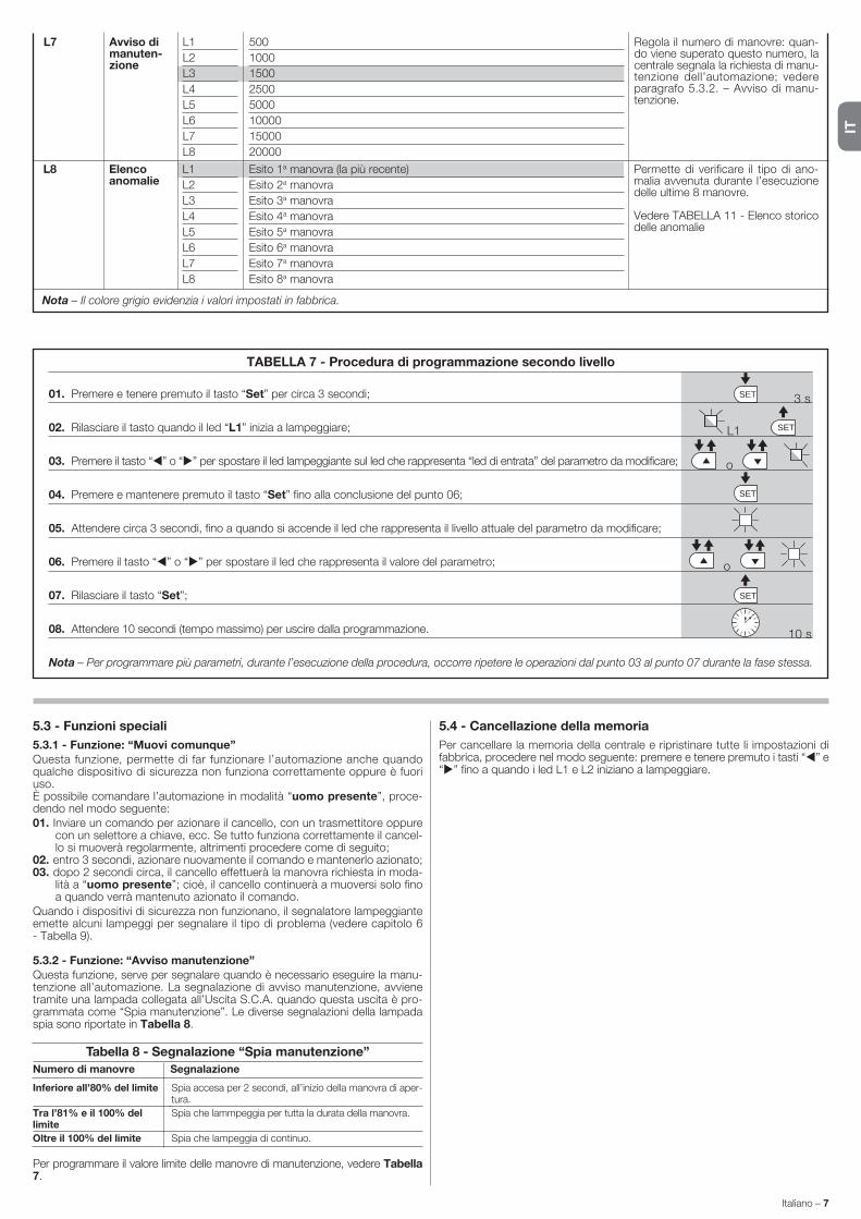
IT
Italiano – 7
5.3 - Funzioni speciali
5.3.1 - Funzione: “Muovi comunque”Questa funzione, permette di far funzionare l’automazione anche quando qualche dispositivo di sicurezza non funziona correttamente oppure è fuori uso.È possibile comandare l’automazione in modalità “uomo presente”, proce-dendo nel modo seguente:01. Inviare un comando per azionare il cancello, con un trasmettitore oppure
con un selettore a chiave, ecc. Se tutto funziona correttamente il cancel-lo si muoverà regolarmente, altrimenti procedere come di seguito;
02. entro 3 secondi, azionare nuovamente il comando e mantenerlo azionato;03. dopo 2 secondi circa, il cancello effettuerà la manovra richiesta in moda-
lità a “uomo presente”; cioè, il cancello continuerà a muoversi solo fino a quando verrà mantenuto azionato il comando.
Quando i dispositivi di sicurezza non funzionano, il se gnalatore lampeggiante emette alcuni lampeggi per segnalare il tipo di problema (vedere capitolo 6 - Tabella 9).
5.3.2 - Funzione: “Avviso manutenzione”Questa funzione, serve per segnalare quando è necessario eseguire la manu-tenzione all’automazione. La segnalazione di avviso manutenzione, avviene tramite una lampada collegata all’Uscita S.C.A. quando questa uscita è pro-grammata come “Spia manutenzione”. Le diverse segnalazioni della lampada spia sono riportate in Tabella 8.
Per programmare il valore limite delle manovre di manutenzione, vedere Tabella 7.
5.4 - Cancellazione della memoria
Per cancellare la memoria della centrale e ripristinare tutte li impostazioni di fabbrica, procedere nel modo seguente: premere e tenere premuto i tasti “ ” e “ ” fino a quando i led L1 e L2 iniziano a lampeggiare.
Tabella 8 - Segnalazione “Spia manutenzione”
Numero di manovre Segnalazione
Spia accesa per 2 secondi, all’inizio della manovra di aper-tura.
Spia che lammpeggia per tutta la durata della manovra.
Spia che lampeggia di continuo.
Inferiore all’80% del limite
Tra l’81% e il 100% del limite
Oltre il 100% del limite
SET
SET
SET
SETL1
o
o
3 s
10 s
Nota – Il colore grigio evidenzia i valori impostati in fabbrica.
L8 L1
L2
L3
L4
L5
L6
L7
L8
Esito 1a manovra (la più recente)
Esito 2a manovra
Esito 3a manovra
Esito 4a manovra
Esito 5a manovra
Esito 6a manovra
Esito 7a manovra
Esito 8a manovra
Permette di verificare il tipo di ano-malia avvenuta durante l’esecuzione delle ultime 8 manovre.
Vedere TABELLA 11 - Elenco storico delle anomalie
Elenco anomalie
L7 L1
L2
L3
L4
L5
L6
L7
L8
500
1000
1500
2500
5000
10000
15000
20000
Regola il numero di manovre: quan-do viene superato questo numero, la centrale segnala la richiesta di manu-tenzione dell’automazione; vedere paragrafo 5.3.2. – Avviso di manu-tenzione.
Avviso di manuten-zione
TABELLA 7 - Procedura di programmazione secondo livello
01. Premere e tenere premuto il tasto “Set” per circa 3 secondi;
02. Rilasciare il tasto quando il led “L1” inizia a lampeggiare;
03. Premere il tasto “ ” o “ ” per spostare il led lampeggiante sul led che rappresenta “led di entrata” del parametro da modificare;
04. Premere e mantenere premuto il tasto “Set” fino alla conclusione del punto 06;
05. Attendere circa 3 secondi, fino a quando si accende il led che rappresenta il livello attuale del parametro da modificare;
06. Premere il tasto “ ” o “ ” per spostare il led che rappresenta il valore del parametro;
07. Rilasciare il tasto “Set”;
08. Attendere 10 secondi (tempo massimo) per uscire dalla programmazione.
Nota – Per programmare più parametri, durante l’esecuzione della procedura, occorre ripetere le operazioni dal punto 03 al punto 07 durante la fase stessa.

IT
8 – Italiano
7 lampeggi brevipausa di 1 secondo7 lampeggi brevi
Anomalia sui circuiti elettrici Attendere almeno 30 secondi e riprovare a inviare un comando ed even-tualmente spegnere anche l’alimentazione; se lo stato rimane potrebbe esserci un guasto grave ed occorre sostituire la scheda elettronica.
8 lampeggi brevipausa di 1 secondo8 lampeggi brevi
È già presente un comando che non consente di eseguire altri comandi
Verificare la natura del comando sempre presente; ad esempio potrebbe essere il comando da un orologio sull’ingresso di “apre”.
9 lampeggi brevipausa di 1 secondo9 lampeggi brevi
L’automazione è stata bloccata da un comando “Blocca l’automazione”.
Sbloccare l’automazione inviando il comando “Sblocca automazione”.
10 lampeggi brevipausa di 1 secondo10 lampeggi brevi
Intervento della funzione“Rilevamento Ostacoli” da encoder
Durante il movimento i motori sono stati bloccati da un maggiore attrito; verificare la causa.
TABELLA 9 - Segnalazioni del segnalatore lampeggiante (FLASH)
Lampeggi Problema Risoluzione
1 lampeggio brevepausa di 1 secondo1 lampeggio breve
Errore sul sistema Bluebus La verifica dei dispositivi collegati al sistema Bluebus, che viene eseguita all’inizio della ma novra, non corrisponde ai dispositivi memorizzati durante la fase di apprendimento. È possibile che ci siano dispositivi scollegati o guasti, quindi occorre verificare e sostituire. Se sono state fatte delle modi-fiche occorre rifare l’apprendimento dei dispositivi (vedere paragrafo 3.4).
2 lampeggi brevipausa di 1 secondo2 lampeggi brevi
Intervento di una fotocellula Una o più fotocellule non danno il consenso al movimento oppure duran-te la corsa hanno provocato una inversione del movimento; verificare se sono presenti ostacoli.
3 lampeggi brevipausa di 1 secondo3 lampeggi brevi
Intervento della funzione“Rilevamento Ostacoli” da limitatore di forza
Durante il movimento i motori hanno incontrato un maggiore sforzo; veri-ficare la causa ed eventualmente aumentare il livello di forza dei motori
4 lampeggi brevipausa di 1 secondo4 lampeggi brevi
Intervento dell’ingresso di STOP All’inizio della manovra o durante il movimento c’è stato un intervento dei dispositivi collegati all’ingresso STOP; verificare la causa.
5 lampeggi brevipausa di 1 secondo5 lampeggi brevi
Errore nei parametri interni dellacentrale di comando
Attendere almeno 30 secondi e poi riprovare a dare un comando ed even-tualmente spegnere anche l’alimentazione; se lo stato rimane, potrebbe esserci un guasto grave ed occorre sostituire la scheda elettronica.
6 lampeggi brevipausa di 1 secondo6 lampeggi brevi
Superato il limite massimo di manovre consecutive o di manovre per ora.
Attendere alcuni minuti in modo da far ritornare il limitatore di ma novre sotto il limite massimo.
Alcuni dispositivi sono predisposti per emettere delle segnalazioni con il quale è possibile riconoscere lo stato di funzionamento oppure di eventuali ano-malie.Se all’uscita FLASH presente sulla centrale viene collegato un lampeggian-te, questo durante l’esecuzione di una manovra, emette un lampeggio con
COSA FARE SE...(guida alla risoluzione dei problemi)6
TABELLA 10 - Segnalazioni dei Led presenti sulla centrale di comando (fig. 7)
Led Problema Risoluzione
BLUEBUSSempre spento
Sempre acceso
1 lampeggio al secondo
2 lampeggi veloci
Serie di lampeggi divisi da una pausadi 1 secondo
Anomalia
Anomalia grave
Tutto regolare
Variazione dello stato degli ingressi
Varie
Verificare se la centrale è alimentata; verificare che i fusibili non siano intervenuti. In questo caso verificare la causa del guasto e sostituirli con altri dello stesso valore
È presente un problema grave: provare a togliere l’alimentazione elettrica alla centrale e se lo stato permane, occorre sostituire la scheda elettronica
Funzionamento regolare della centrale
È regolare se avviene una variazione in uno degli ingressi (PP, STOP, OPEN, CLOSE): intervento delle fotocellule oppure viene trasmesso un comando con un trasmettitore
Fare riferimento alla Tabella 9
STOPSempre spento
Sempre acceso
Intervento dei dispositivi collegati all’ingresso STOP
Tutto regolare
Verificare i dispositivi dell’ingesso STOP
Ingresso STOP attivo
P.P.Sempre spento
Sempre acceso
Tutto regolare
Intervento dell’ingresso P.P.
Ingresso P.P. non attivo
È regolare se è attivo il dispositivo collegato all’ingresso P.P.
OPENSempre spento
Sempre acceso
Tutto regolare
Intervento dell’ingresso OPEN
Ingresso OPEN non attivo.
È regolare se è attivo il dispositivo collegato all’ingresso OPEN
CLOSESempre spento
Sempre acceso
Tutto regolare
Intervento dell’ingresso CLOSE
Ingresso CLOSE non attivo.
È regolare se è attivo il dispositivo collegato all’ingresso CLOSE
cadenza di 1 secondo. Se si verificano delle anomalie, il lampeggiane emette dei lampeggi più brevi; questi vengono ripetuti due volte divisi da una pausa di 1 secondo. Nella Tabella 9 sono descritte la causa e la soluzione per ogni tipo di segnalazione.Anche i Led presenti sulla centrale emettono delle segnalazioni; nella Tabella 10 sono descritte la causa e la soluzione per ogni tipo di segnalazione.È possibile controllare le eventuali anomalie verificatesi durante l’esecuzione delle utlime 8 manovre; fare riferimento alla Tabella 11.
L1 - L2 Lampeggio lento Variazione del numero di dispositivicollegati al Bluebus oppure apprendi-mento dispositivo non eseguito
È necessario eseguire l’apprendimento dei dispositivi (vedere paragrafo 3.6)
L3 - L4 Lampeggio lento Non è mai stato eseguito l’apprendi-mento delle posizioni degli arresti meccanici
È necessario eseguire l’apprendimento (vedere paragrafo 3.6).
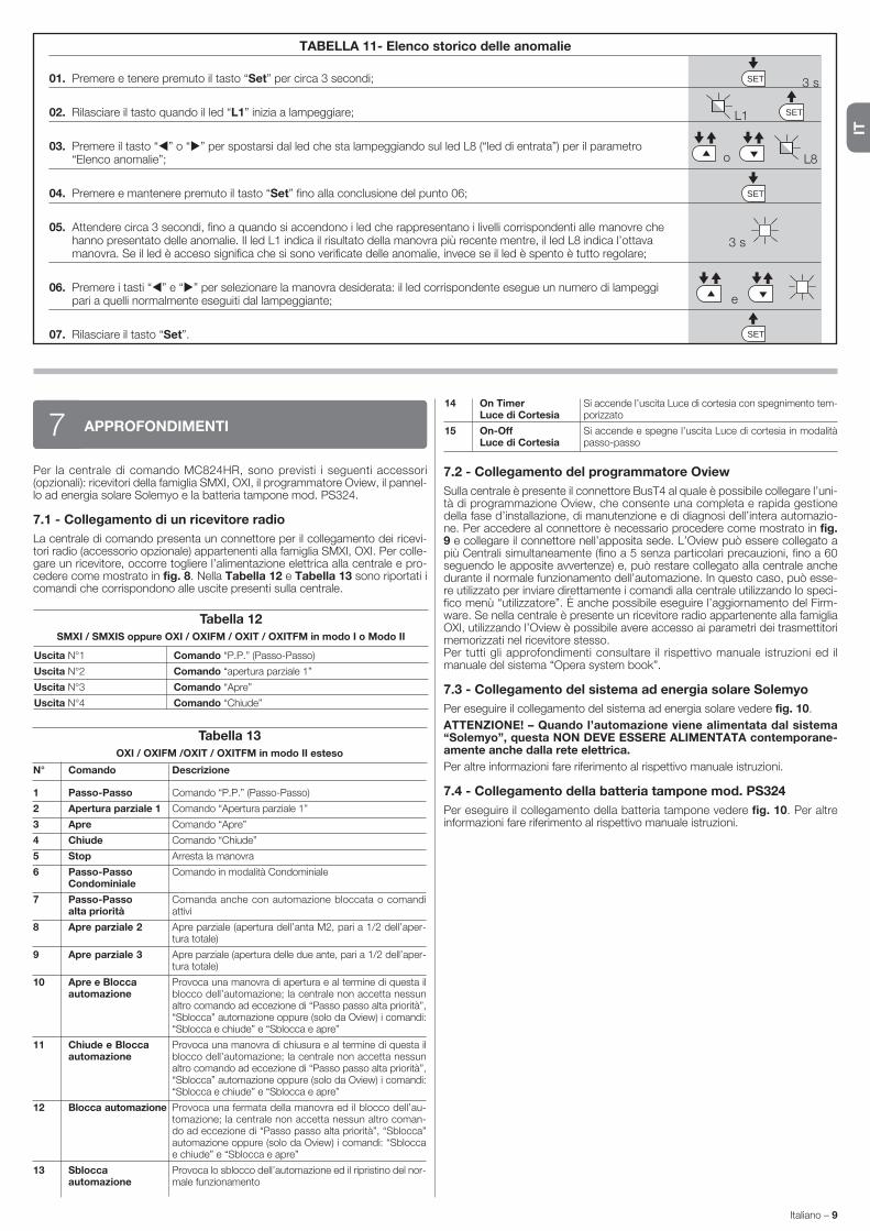
IT
Italiano – 9
Tabella 13
OXI / OXIFM /OXIT / OXITFM in modo II esteso
N° Comando Descrizione
Per la centrale di comando MC824HR, sono previsti i seguenti accessori (opzionali): ricevitori della famiglia SMXI, OXI, il programmatore Oview, il pannel-lo ad energia solare Solemyo e la batteria tampone mod. PS324.
7.1 - Collegamento di un ricevitore radio
La centrale di comando presenta un connettore per il collegamento dei ricevi-tori radio (accessorio opzionale) appartenenti alla famiglia SMXI, OXI. Per colle-gare un ricevitore, occorre togliere l’alimentazione elettrica alla centrale e pro-cedere come mostrato in fig. 8. Nella Tabella 12 e Tabella 13 sono riportati i comandi che corrispondono alle uscite presenti sulla centrale.
APPROFONDIMENTI7
Tabella 12
SMXI / SMXIS oppure OXI / OXIFM / OXIT / OXITFM in modo I o Modo II
Comando “P.P.” (Passo-Passo)
Comando “apertura parziale 1”
Comando “Apre”
Comando “Chiude”
Uscita N°1
Uscita N°2
Uscita N°3
Uscita N°4
1 Passo-Passo
2 Apertura parziale 1
3 Apre
4 Chiude
5 Stop
6 Passo-Passo Condominiale
7 Passo-Passo alta priorità
8 Apre parziale 2
9 Apre parziale 3
10 Apre e Blocca automazione
11 Chiude e Blocca automazione
12 Blocca automazione
13 Sblocca automazione
7.2 - Collegamento del programmatore Oview
Sulla centrale è presente il connettore BusT4 al quale è possibile collegare l’uni-tà di programmazione Oview, che consente una completa e rapida gestione della fase d’installazione, di manutenzione e di diagnosi dell’intera automazio-ne. Per accedere al connettore è necessario procedere come mo strato in fig. 9 e collegare il connettore nell’apposita sede. L’Oview può essere collegato a più Centrali simultaneamente (fino a 5 senza particolari precauzioni, fino a 60 seguendo le apposite avvertenze) e, può restare collegato alla centrale anche durante il normale funzionamento dell’automazione. In questo caso, può esse-re utilizzato per inviare direttamente i comandi alla centrale utilizzando lo speci-fico menù “utilizzatore”. È anche possibile eseguire l’aggiornamento del Firm-ware. Se nella centrale è presente un ricevitore radio appartenente alla famiglia OXI, utilizzando l’Oview è possibile avere accesso ai parametri dei trasmettitori memorizzati nel ricevitore stesso.Per tutti gli approfondimenti consultare il rispettivo manuale istruzioni ed il manuale del sistema “Opera system book”.
7.3 - Collegamento del sistema ad energia solare Solemyo
Per eseguire il collegamento del sistema ad energia solare vedere fig. 10.
ATTENZIONE! – Quando l’automazione viene alimentata dal sistema “So lemyo”, questa NON DEVE ESSERE ALIMENTATA contemporane-amente anche dalla rete elettrica.
Per altre informazioni fare riferimento al rispettivo manuale istruzioni.
7.4 - Collegamento della batteria tampone mod. PS324
Per eseguire il collegamento della batteria tampone vedere fig. 10. Per altre informazioni fare riferimento al rispettivo manuale istruzioni.
Comando “P.P.” (Passo-Passo)
Comando “Apertura parziale 1”
Comando “Apre”
Comando “Chiude”
Arresta la manovra
Comando in modalità Condominiale
Comanda anche con automazione bloccata o comandi attivi
Apre parziale (apertura dell’anta M2, pari a 1/2 dell’aper-tura totale)
Apre parziale (apertura delle due ante, pari a 1/2 dell’aper-tura totale)
Provoca una manovra di apertura e al termine di questa il blocco dell’automazione; la centrale non accetta nessun altro comando ad eccezione di “Passo passo alta priorità”, “Sblocca” automazione oppure (solo da Oview) i comandi: “Sblocca e chiude” e “Sblocca e apre”
Provoca una manovra di chiusura e al termine di questa il blocco dell’automazione; la centrale non accetta nessun altro comando ad eccezione di “Passo passo alta priorità”, “Sblocca” automazione oppure (solo da Oview) i comandi: “Sblocca e chiude” e “Sblocca e apre”
Provoca una fermata della manovra ed il blocco dell’au-tomazione; la centrale non accetta nessun altro coman-do ad eccezione di “Passo passo alta priorità”, “Sblocca” automazione oppure (solo da Oview) i comandi: “Sblocca e chiude” e “Sblocca e apre”
Provoca lo sblocco dell’automazione ed il ripristino del nor-male funzionamento
14 On Timer Luce di Cortesia
15 On-Off Luce di Cortesia
Si accende l’uscita Luce di cortesia con spegnimento tem-porizzato
Si accende e spegne l’uscita Luce di cortesia in modalità passo-passo
SET
SET
SET
SETL1
o
e
3 s
L8
TABELLA 11- Elenco storico delle anomalie
01. Premere e tenere premuto il tasto “Set” per circa 3 secondi;
02. Rilasciare il tasto quando il led “L1” inizia a lampeggiare;
03. Premere il tasto “ ” o “ ” per spostarsi dal led che sta lampeggiando sul led L8 (“led di entrata”) per il parametro “Elenco anomalie”;
04. Premere e mantenere premuto il tasto “Set” fino alla conclusione del punto 06;
05. Attendere circa 3 secondi, fino a quando si accendono i led che rappresentano i livelli corrispondenti alle manovre che hanno presentato delle anomalie. Il led L1 indica il risultato della manovra più recente mentre, il led L8 indica l’ottava
manovra. Se il led è acceso significa che si sono verificate delle anomalie, invece se il led è spento è tutto regolare;
06. Premere i tasti “ ” e “ ” per selezionare la manovra desiderata: il led corrispondente esegue un numero di lampeggi pari a quelli normalmente eseguiti dal lampeggiante;
07. Rilasciare il tasto “Set”.
3 s

IT
10 – Italiano
AVVERTENZE: • Tutte le caratteristiche tecniche riportate, sono riferite ad una temperatura ambientale di 20°C (± 5°C). • Nice S.p.a. si riserva il diritto di apportare modifiche al prodotto in qualsiasi momento lo riterrà necessario, mantenendone comunque la stessa funzionalità e destinazione d’uso.
Alimentazione MC824HR 230 Vac (+10% -15%) 50/60 Hz Alimentazione MC824HR/V1 120 Vac (+10% -15%) 50/60 Hz
Potenza nominale assorbita dalla rete elettrica 200 W
Potenza assorbita del connettore batteria della centrale con funzionamento “standby-Tutto” inferiore a 100 mW (compreso un ricevitore con connettore di tipo SM)
Uscita lampeggiante [*] 1 lampeggiante LUCYB (lampada 12 V, 21 W)
Uscita elettroserratura [*] 1 elettroserratura da 12 Vac max 15 VA
Uscita spia cancello aperto [*] 1 lampada 24 V massimo 4 W (la tensione d’uscita può variare tra -30 e +50%, l’uscita può comandare anche piccoli relè)
Uscita BLUEBUS 1 uscita con carico massimo di 15 unità Bluebus (massimo 6 coppie di fotocellule MOFB o MOFOB + 2 coppie di fotocellule
MOFB o MOFOB indirizzate come dispositivi di apertura + massimo 4 dispositivi di comando MOMB o MOTB
Ingresso STOP per contatti normalmente chiusi, normalmente aperti oppure a resistenza costante 8,2 kΩ; in auto-apprendimento (una variazione
rispetto allo stato memorizzato provoca il comando “STOP”)
Ingresso PP per contatti normalmente aperti (la chiusura del contatto provoca il comando Passo Passo)
Ingresso OPEN per contatti normalmente aperti (la chiusura del contatto provoca il comando APRE)
Ingresso CLOSE per contatti normalmente aperti (la chiusura del contatto provoca il comando CHIUDE)
Innesto radio connettore SM per ricevitori della famiglia SMXI, OXI e OXIFM
Ingresso ANTENNA Radio 50 Ω per cavo tipo RG58 o simili
Funzioni programmabili 8 funzioni di tipo ON-OFF e 8 funzioni regolabili
• Auto apprendimento dei dispositivi collegati all’uscita BlueBus
Funzioni in auto apprendimento • Auto apprendimento del tipo di dispositivo collegato al morsetto “STOP” (contatto NA, NC o resistenza 8,2 kΩ)
• Auto apprendimento della corsa delle ante e calcolo in automatico dei punti di rallentamento ed apertura parziale (diversificati per tipo di installazione)
Temperatura di funzionamento da - 20 °C a + 50 °C
Utilizzo in atmosfera particolarmente acida NO
o salina o potenzialmente esplosiva
Grado di protezione IP 54 con contenitore integro
Dimensioni (mm) 310 x 232 x H 122
Peso (kg) 4,1
[*] Le uscite Lampaggiante, Elettroserratura Spia Cancello Aperto possono essere programmate con altre funzioni (vedere “TABELLA 4 - Funzioni 1° livello”; oppure tramite program-matore Oview, vedere capitolo 7.2). Le caratteristiche elettriche dell’uscita si adeguano in base alla programmazione:
lampeggiante: lampada 12Vdc, 21 Wmax
elettroserratura: 12Vac 15 VAmax
altre uscite (tutti i tipi): 1 lampada o relè 24Vdc (-30 e +50%), 4 Wmax
CARATTERISTICHE TECNICHE DEL PRODOTTO
MANUTENZIONE DEL PRODOTTO8Per mantenere costante il livello di sicurezza e per garantire la massima durata dell’intera automazione è necessaria una manutenzione regolare.La manutenzione deve essere effettuata nel pieno rispetto delle prescrizioni sulla sicurezza del presente manuale e secondo quanto previsto dalle leggi e normative vigenti.
Importante – Durante le fasi di manutenzione oppure di pulizia del prodotto, Scollegare la centrale dall’alimentazione elettrica.
Per gli altri dispositivi diversi da MC824HR seguire quanto previsto nei rispettivi piani manutenzione.
Per MC824HR è necessaria una manutenzione programmata al massimo entro 6 mesi o 20.000 manovre dalla precedente manutenzione.
Per eseguire la manutenzione procedere nel modo seguente: 01. Scollegare qualsiasi sorgente di alimentazione elettrica, comprese le even-
tuali batterie tampone; 02. Verificare lo stato di deterioramento di tutti i materiali che compongono la
centrale con particolare attenzione a fenomeni di erosione o di ossidazione delle parti; sostituire le parti che non forniscono sufficienti garanzie;
03. Ricollegare le sorgenti di alimentazione elettrica ed eseguire tutte le prove e le verifiche previste nel capitolo 4.1 - Collaudo.
SMALTIMENTO DEL PRODOTTO
Questo prodotto è parte integrante dell’automazione, e dunque, deve es sere smaltito insieme con essa.Come per le operazioni d’installazione, anche al termine della vita di questo prodotto, le operazioni di smantellamento devono essere eseguite da perso-nale qualificato.Questo prodotto è costituito da vari tipi di materiali: alcuni possono essere riciclati, altri devono essere smaltiti. Informatevi sui sistemi di riciclaggio o smaltimento pre-visti dai regolamenti vigenti sul vostro territorio, per questa categoria di prodotto.Attenzione! – alcune parti del prodotto possono contenere sostanze inqui-nanti o pericolose che, se disperse nell’ambiente, potrebbero provocare effetti dannosi sull’ambiente stesso e sulla salute umana.Come indicato dal simbolo a lato, è vietato gettare questo prodot-to nei rifiuti domestici. Eseguire quindi la “raccolta separata” per lo smaltimento, secondo i metodi previsti dai regolamenti vigenti sul vostro territorio, oppure riconsegnare il prodotto al venditore nel momento dell’acquisto di un nuovo prodotto equivalente.Attenzione! – i regolamenti vigenti a livello locale possono prevedere pesanti sanzioni in caso di smaltimento abusivo di questo prodotto.
Smaltimento della batteria tampone (se presente)
Attenzione! – La batteria scarica contiene sostanze inquinanti e quindi, non deve essere buttata nei rifiuti comuni.
Occorre smaltirla utilizzando i metodi di raccolta ‘separata’, previsti dalle nor-mative vigenti nel vostro territorio.

FR
Français – 1
FRANÇAIS
SommaireRECOMMANDATIONS ET PRÉCAUTIONS GÉNÉRALES . . . . . . . . . . . . 1Recommandations pour la sécurité. . . . . . . . . . . . . . . . . . . . . . . . . . . . . . . . 1Recommandations pour l’installation . . . . . . . . . . . . . . . . . . . . . . . . . . . . . . 1Recommandations pour l’utilisation . . . . . . . . . . . . . . . . . . . . . . . . . . . . . . . 1
1 - DESCRIPTION DU PRODUIT ET TYPE D’UTILISATION . . . . . . . . . . 1
2 - INSTALLATION . . . . . . . . . . . . . . . . . . . . . . . . . . . . . . . . . . . . . . . . . . . 12.1 - Contrôles avant l’installation . . . . . . . . . . . . . . . . . . . . . . . . . . . . . . . . . 12.2 - Limites d’utilisation du produit . . . . . . . . . . . . . . . . . . . . . . . . . . . . . . . 22.3 - Installation typique . . . . . . . . . . . . . . . . . . . . . . . . . . . . . . . . . . . . . . . . 22.4 - Installation de la logique de commande . . . . . . . . . . . . . . . . . . . . . . . . 2
3 - BRANCHEMENTS ÉLECTRIQUES . . . . . . . . . . . . . . . . . . . . . . . . . . . 23.1 - Description des connexions électriques . . . . . . . . . . . . . . . . . . . . . . . . 23.2 - Connexions électriques de la logique de commande MC824HR . . . . . . 33.3 - Connexion d’autres dispositifs à MC824HR . . . . . . . . . . . . . . . . . . . . . 33.4 - Adressage des dispositifs connectés à MC824HR . . . . . . . . . . . . . . . . 33.5 - Première mise en service et vérification des connexions . . . . . . . . . . . . 33.6 - Reconnaissance des dispositifs connectés à MC824HR . . . . . . . . . . . 33.7 - Reconnaissance des positions des fins de course mécaniques . . . . . . 3 3.7.1 - Reconnaissance en mode automatique . . . . . . . . . . . . . . . . . . 4 3.7.2 - Reconnaissance en mode manuel . . . . . . . . . . . . . . . . . . . . . . 4 3.7.3 - Reconnaissance en mode mixte . . . . . . . . . . . . . . . . . . . . . . . . 43.8 - Vérification du mouvement des vantaux du portail . . . . . . . . . . . . . . . . 4
4 - ESSAI ET MISE EN SERVICE . . . . . . . . . . . . . . . . . . . . . . . . . . . . . . . 44.1 - Essai . . . . . . . . . . . . . . . . . . . . . . . . . . . . . . . . . . . . . . . . . . . . . . . . . . 54.2 - Mise en service . . . . . . . . . . . . . . . . . . . . . . . . . . . . . . . . . . . . . . . . . . 5
5 - PROGRAMMATION . . . . . . . . . . . . . . . . . . . . . . . . . . . . . . . . . . . . . . . 55.1 - Programmation du premier niveau (ON-OFF) . . . . . . . . . . . . . . . . . . . . 55.2 - Programmation deuxième niveau (paramètres réglables) . . . . . . . . . . . 65.3 - Fonctions spéciales . . . . . . . . . . . . . . . . . . . . . . . . . . . . . . . . . . . . . . . 75.4 - Effacement de la mémoire . . . . . . . . . . . . . . . . . . . . . . . . . . . . . . . . . . 8
6 - QUE FAIRE SI… (guide pour la résolution des problèmes) . . . . . . . 8
7 - APPROFONDISSEMENTS . . . . . . . . . . . . . . . . . . . . . . . . . . . . . . . . . . 97.1 - Connexion d’un récepteur radio . . . . . . . . . . . . . . . . . . . . . . . . . . . . . . 97.2 - Connexion du programmateur Oview . . . . . . . . . . . . . . . . . . . . . . . . . . 97.3 - Connexion du système à énergie solaire Solemyo . . . . . . . . . . . . . . . . 97.4 - Connexion de la batterie tampon mod. PS324 . . . . . . . . . . . . . . . . . . . 9
8 - MAINTENANCE DU PRODUIT . . . . . . . . . . . . . . . . . . . . . . . . . . . . . . 10
MISE AU REBUT DU PRODUIT . . . . . . . . . . . . . . . . . . . . . . . . . . . . . . . 10
CARACTÉRISTIQUES TECHNIQUES DU PRODUIT . . . . . . . . . . . . . . . 10
DÉCLARATION CE DE CONFORMITÉ . . . . . . . . . . . . . . . . . . . . . . . . . . . II
Instructions et recommandations destinées à l’utilisateur . . . . . . . . . VIIImages . . . . . . . . . . . . . . . . . . . . . . . . . . . . . . . . . . . . . . . . . . . . . . . . . . . XII
MC824HR est une centrale électronique pour l’automatisation des barrières et des battants motorisés de série Toona modèle 5624l (voir le paragraphe « 2.2 Limites d’utilisation du produit »). ATTENTION ! – Toute autre utilisation que celle décrite et dans des conditions ambiantes différentes de celles indi-quées dans ce guide doit être considérée comme impropre et interdite !La logique de commande est prévue pour être connectée à des disposi-tifs appartenant au Système Opera, au système Bluebus et au système d’alimentation par l’énergie solaire Solemyo.Si elle est alimentée par le secteur, la logique de commande peut loger une batterie tampon (mod. PS324, accessoire en option) qui en cas de panne de l’énergie électrique (black-out électrique) garantit à l’automatisme l’exécution de quelques manœuvres dans les heures qui suivent.Parmi les autres accessoires disponibles, il y a les récepteurs de type embro-chable « SM » (SMXI, OXI etc.).
DESCRIPTION DU PRODUIT ET TYPE D’UTILISATION1
Recommandations pour la sécurité
• ATTENTION ! – Ce guide contient des instructions et des recomman-dations importantes pour la sécurité des personnes. Une installation erronée peut causer de graves blessures. Avant de procéder à l’installation, il faut lire attentivement toutes les parties du guide. En cas de doutes, suspendre l’installation et demander des éclaircissements au Service Assistance Nice.
• ATTENTION ! – Instructions importantes : conserver avec soin ce guide pour faciliter les éventuelles interventions futures de mainte-nance ou de mise au rebut du produit.
• ATTENTION ! – Conformément à la plus récente législation europé-en ne, la réalisation d’un vantail ou d’un portail automatique doit res-pecter les normes prévues par la Directive 2006/42/CE (ex 98/37/CE) (Directive Machines) et en particulier, les normes EN 12445; EN 12453; EN 12635 et EN 13241-1 qui permettent de déclarer la conformité de l’automatisation. Pour cette raison, toutes les opérations d’installa-tion, de branchement, d’essai et de maintenance du produit doivent être confiées exclusivement à un technicien qualifié et compétent !
Recommandations pour l’installation• Avant de commencer l’installation vérifier si le présent produit est adapté au
type d’utilisation désirée (voir « Limites d’utilisation » paragraphe 2.2 et les « Caractéristiques techniques du produit »). S’il n’est pas adapté, NE PAS procéder à l’installation.
• Le contenu du présent manuel se réfère à une installation type, comme celle décrite fig. 2a.
• Toutes les opérations d’installation et de maintenance doivent être effectuées avec l’automatisation débranchée. Si le dispositif de décon-nexion de l’alimentation n’est pas visible du lieu où est positionné l’automa-tisme, avant de commencer le travail accrocher sur le dispositif de décon-nexion un panneau avec écrit “ATTENTION ! MAINTENANCE EN COURS”.
• Prévoir, sur la ligne d’alimentation de l’installation, un dispositif de déconne-xion avec une distance d’ouverture des contacts permettant la déconnexion complète dans les conditions prescrites par la catégorie de surtension III.
• La logique de commande doit être connectée à une ligne d’alimentation élec-trique avec mise à la terre.
• Au cours de l’installation, manipuler le produit avec précaution en évitant les écrasements, les chocs, les chutes ou le contact avec des liquides de n’im-porte quelle nature. Ne pas mettre le produit à proximité de fortes sources de chaleur ni l’exposer à des flammes vives. Toutes ces actions peuvent l’endommager et causer des problèmes de fonctionnement ou des situa-tions de danger. Si cela se produit, suspendre immédiatement l’installation et s’adresser au service après-vente Nice.
• Ne pas effectuer de modifications sur une partie quelconque du produit. Les opérations non autorisées ne peuvent que provoquer des problèmes de fonctionnement. Le constructeur décline toute responsabilité pour les dom-mages dérivant de modifications arbitraires au produit.
• Les matériaux de l’emballage du produit doivent être mis au rebut dans le plein respect des normes locales en vigueur.
Recommandations pour l’utilisation• Le produit n’est pas destiné à être utilisé par des personnes (enfants com-
pris) aux capacités physiques, sensorielles ou mentales réduites, ou man-quant d’expérience ou de connaissances, à moins que celles-ci aient pu bénéficier, par l’intermédiaire d’une personne responsable de leur sécurité, d’une surveillance ou d’instructions sur l’utilisation du produit.
• Les enfants se trouvant à proximité de l’automatisme doivent être surveillés pour éviter qu’ils jouent avec celui-ci.
• Ne pas laisser les enfants jouer avec les dispositifs de commande fixes. Garder les dispositifs de commande portables (à distance) hors de la portée des enfants.
RECOMMANDATIONS ET PRÉCAUTIONS GÉNÉRALES
2.1 - Contrôles avant l’installation
Avant d’effectuer l’installation, il est nécessaire de vérifier l’intégrité des compo-sants du produit, l’adéquation du modèle choisi et son adaptation au lieu prévu
INSTALLATION2
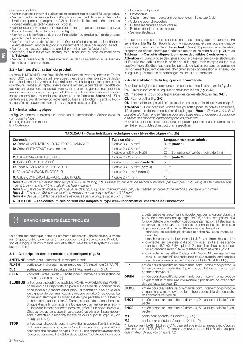
FR
2 – Français
BRANCHEMENTS ÉLECTRIQUES3
La connexion électrique entre les différents dispositifs (photocellules, claviers numériques, lecteurs de cartes à transpondeur, etc.) présents dans l’installa-tion et la logique de commande, doit être effectuée à travers le système « Blue-bus » de Nice.
3.1 - Description des connexions électriques (fig. 6)
ANTENNE entrée pour l’antenne d’un récepteur radio
FLASH sortie pour 1 clignotant avec lampe de 12 V (maximum 21 W). [*]
ELS sortie pour serrure électrique de 12 Vca (maximum 15 VA) [*]
S.C.A. « Voyant Portail Ouvert » : sortie pour 1 lampe de signalisation de 24 V et maximum 4 W. [*]
BLUEBUS entrée pour dispositifs compatibles (MOFB, MOFOB, MOB et MOTB) ; connexion des dispositifs en parallèle à l’aide de 2 conducteurs dans lesquels passent aussi bien l’alimentation électrique que les signaux de communication ; aucune polarité à respecter. La connexion électrique à utiliser est de type parallèle et n’a besoin de respecter aucune polarité. Durant la phase de reconnaissance, chaque dispositif connecté à la logique de commande sera recon-nu individuellement par cette dernière, grâce à un code univoque. Chaque fois qu’un dispositif sera ajouté ou éliminé, il sera néces-saire d’effectuer la reconnaissance de celui-ci par la logique (voir paragraphe 3.6).
STOP entrée pour dispositifs dont l’intervention provoque l’arrêt immédiat de la manœuvre en cours, suivi d’une brève inversion ; possibilité de connecter des contacts de type NO, NF ou des dispositifs avec sortie à résistance constante 8,2 kΩ (bords sensibles). Tout dispositif connecté
à cette entrée est reconnu individuellement par la logique durant la phase de reconnaissance (paragraphe 3.6) ; dans cette phase, si la logique détecte une variation quelconque par rapport à l’état appris, elle provoque un STOP. Il est possible de connecter à cette entrée un ou plusieurs dispositifs même différents les uns des autres :
– connecter en parallèle plusieurs dispositifs NO, sans limites de quantité ;
– brancher en série plusieurs dispositifs NF, sans limites de quantité ; – connecter en parallèle 2 dispositifs avec sortie à résistance
constante 8,2 kΩ. S’il y a plus de 2 dispositifs, il faut les connec-ter en cascade avec 1 seule résistance terminale de 8,2 kΩ ;
– connecter en parallèle 2 dispositifs NO et NF, en mettant en série au contact NF une résistance de 8,2 kΩ (cela rend possible aussi la combinaison entre 3 dispositifs NO - NF et 8,2 kΩ) ;
P.P. entrée pour dispositifs de commande dont l’intervention provoque la manœuvre en mode Pas à pas ; possibilité de connecter des contacts de type NO
OPEN entrée pour dispositifs de commande dont l’intervention provoque uniquement la manœuvre d’ouverture ; possibilité de connecter des contacts de type NO
CLOSE entrée pour dispositifs de commande dont l’intervention provoque uniquement la manœuvre de fermeture ; possibilité de connecter des contacts de type NO
ENC1 entrée encodeur - opérateur 1 (borne 1, 2) ; aucune polarité à res-pecter ;
ENC2 entrée encodeur - opérateur 2 (borne 4, 5) ; aucune polarité à res-pecter ;
M1 sortie pour opérateur 1 (borne 7, 8, 9) ;
M2 sortie pour opérateur 2 (borne 10, 11, 12) ;
[*] Les sorties FLASH, ELS et S.C.A. peuvent être programmées avec d’autres fonctions (voir « TABLEAU 4 - Fonctions 1er niveau » ; ou bien à l’aide du pro-grammateur Oview, voir chapitre 7.2).
pour son installation :• Vérifier que tout le matériel à utiliser est en excellent état et adapté à l’usage prévu.• Vérifier que toutes les conditions d’application rentrent dans les limites d’uti-
lisation du produit (paragraphe 2.2) et dans les limites indiquées dans les « caractéristiques techniques » du produit.
• Vérifier que l’environnement choisi pour l’installation est compatible avec l’encombrement total du produit (voir fig. 1).
• Vérifier que la surface choisie pour l’installation du produit est solide et peut garantir une fixation stable.
• Vérifier que la zone de fixation de l’opérateur n’est pas sujette à inondation ; éventuellement, monter le produit suffisamment soulevé par rapport au sol.
• Vérifier que l’espace autour du produit permet un accès facile et sûr.• Vérifier que tous les câbles électriques à utiliser sont du type énuméré dans
le Tableau 1.• Vérifier la présence de butées mécaniques dans l’installation aussi bien en
fermeture qu’en ouverture.
2.2 - Limites d’utilisation du produit
La centrale MC824HR peut être utilisée exclusivement avec les opérateurs Toona mod. 5624I ; ces moteurs sont reversibles : c’est-à-dire, il est possible de dépla-cer manuellement les vantaux du portail sans avoir à bloquer manuellement les opérateurs. Grâce à un capteur inséré dans le moteur, la centrale est capable de détecter le mouvement manuel des vantaux et en outre de gérer correctement les manoeuvres successives ; ceci permet d’éviter que les vantaux viennent cogner contre les fermetures mécaniques d’ouverture et de fermeture. Attention ! - Si la centrale n’est pas alimentée correctement ou bien si la fonction « stand by tout » est activée, le mouvement manuel des vantaux ne sera pas détecté.
2.3 - Installation typique
La fig. 2a montre un exemple d’installation d’automatisation réalisée avec les composants Nice :a - Logique de commandeb - Opérateur
c - Indicateur clignotantd - Photocellulee - Clavier numérique - Lecteur à transpondeur - Sélecteur à cléf - Colonne pour photocelluleg - Butées mécaniques en ouvertureh - Butée mécanique en fermeturei - Serrure électrique
Ces composants sont positionnés selon un schéma typique et commun. En se référant à la fig. 2a, établir la position approximative dans laquelle chaque composant prévu sera installé. Important – Avant de procéder à l’installation, préparer les câbles électriques nécessaires en se référant à la fig. 2a et au Ta bleau 1, « Caractéristiques techniques des câbles électriques ».Attention – Durant la pose des gaines pour le passage des câbles électriques et l’entrée des câbles dans le boîtier de la logique, tenir compte du fait que des éventuels dépôts d’eau dans les puits de dérivation ou dans les gaines de raccordement peuvent créer des phénomènes de condensation à l’intérieur de la logique qui risquent d’endommager les circuits électroniques.
2.4 - Installation de la logique de commande
Pour fixer la logique de commande, procéder comme illustré dans la fig. 3 :
01. Ouvrir le boîtier de la logique en dévissant les vis (fig. 3-A) ;
02. Préparer les trous pour le passage des câbles électriques (fig. 3-B) ;
03. Fixer le boîtier (fig. 3-C) ;
04. Il est maintenant possible d’effectuer les connexions électriques : voir chap. 3.
Attention ! – Pour préparer l’entrée des goulottes pour les câbles électriques, il faut percer le dessous du boîtier de la logique. Note – Si nécessaire, il est possible d’utiliser l’entrée latérale pour les câbles mais uniquement à condition d’utiliser des raccords appropriés pour les goulottes.Pour effectuer l’installation des autres dispositifs présents dans l’automatisme, se référer aux guides d’instructions respectives.
Connexion Type de câble Longueur maximum admise
A: Câble ALIMENTATION LOGIQUE DE COMMANDE 1 câble 3 x 1,5 mm2 30 m (note 1)
B: Câble CLIGNOTANT avec antenne 1 câble 2 x 0,5 mm2 20 m 1 câble blindé type RG58 20 m (longueur conseillée : moins de 5 m)
C: Câble DISPOSITIFS BLUEBUS 1 câble 2 x 0,5 mm2 20 m (note 2)
D: Câble SÉLECTEUR À CLÉ 2 câbles 2 x 0,5 mm2 (note 3) 50 m
E: Câble ALIMENTATION OPÉRATEUR 1 câble 3 x 1,5 mm2 (note 4) 10 m
F: Câble CONNEXION ENCODEUR 1 câble 2 x 1 mm2 (note 4) 10 m
G: Câble CONNEXION SERRURE ÉLECTRIQUE 1 câble 2 x 1 mm2 10 m
Note 1 – Si le câble d’alimentation fait plus de 30 m de long, il faut utiliser un câble d’une section supérieure (par exemple 3 x 2,5 mm²) et il faut réaliser une mise à la terre de sécurité à proximité de l’automatisme.Note 2 – Si le câble Bluebus fait plus de 20 m de long, jusqu’à un maximum de 40 m, il faut utiliser un câble d’une section supérieure (2 x 1 mm²).Note 3 – Ces deux câbles peuvent être remplacés par un unique câble 4 x 0,25 mm².Note 4 – Ces deux câbles peuvent être remplacés par un unique câble 5 x 1,5 mm².
ATTENTION ! – Les câbles utilisés doivent être adaptés au type d’environnement où est effectuée l’installation.
TABLEAU 1 - Caractéristiques techniques des câbles électriques (fig. 2b)

FR
Français – 3
3.2 - Connexions électriques de la logique de commande MC824HR
Après avoir fixé le boîtier de la logique et préparé les trous pour le passage des câbles électriques (chap. 2.4 et fig. 3), effectuer les connexions électriques :
ATTENTION !– Toutes les connexions électriques doivent être effectuées en l’ab-sence d’alimentation de secteur et avec la batterie tampon déconnec-tée si elle est présente dans l’installation.– Les opérations de branchement doivent être effectuées exclusive-ment par du personnel qualifié.– Sur la ligne électrique d’alimentation, il faut prévoir un dispositif assurant la déconnexion complète de l’automatisation par rapport au secteur. Le dispositif doit avoir une distance d’ouverture entre les contacts permettant une décon-nexion complète dans les conditions prévues par la catégorie de surtension III, conformément aux règles d’installation. Ce dispositif, en cas de besoin, garantit une déconnexion sûre et rapide de l’alimentation ; il doit donc être placé si pos-sible dans une position visible depuis l’automatisme. S’il se trouve à distance, dans une position non visible, il faut prévoir un système empêchant l’é ventuelle reconnexion accidentelle ou non autorisée de l’alimentation, pour conjurer tout danger. Le dispositif de connexion n’est pas fourni avec le produit.
01. Connecter d’abord le câble d’alimentation électrique (fig. 4) et le bloquer avec le presse-étoupe ;
02. Connecter ensuite les câbles électriques des moteurs M1 et M2, en res-pectant les symboles sur l’étiquette (fig. 5) :
a) connecter à la borne M1 le moteur qui actionne le vantail inférieur (le deuxième qui commence la manœuvre d’ouverture) puis l’encodeur res-pectif aux bornes 1-2 ;
b) connecter à la borne M2 le moteur qui actionne le vantail supérieur (le premier qui commence la manœuvre d’ouverture) puis l’encodeur respectif aux bornes 4-5.
IMPORTANT ! – Si l’installation ne comporte qu’un seul opérateur, le connecter à la borne M2 en laissant libre la borne M1 ;
03. Ensuite, connecter les câbles électriques des différents dispositifs présents en faisant référence à la fig. 6 et voir paragraphe 3.3. Note – Pour faciliter les connexions des câbles, on peut extraire les bornes de leur logement.
3.3 - Connexion d’autres dispositifs à MC824HR
S’il faut alimenter d’autres dispositifs prévus dans l’installation, par exemple un lecteur de cartes à transpondeur ou l’éclairage du sélecteur à clé, il est possible de connecter ces dispositifs à la logique de commande sur les bornes « P.P. (positif) » et « STOP (négatif) » (fig. 6). La tension d’alimentation est de 24 Vcc (-30 % ÷ +50 %) avec courant maximum disponible de 200 mA.Note – La tension disponible aux bornes « P.P. » et « STOP » reste présente même quand la fonction « Stand By » est activée sur la carte.
3.4 - Adressage des dispositifs connectés à MC824HR
Pour permettre à la logique de reconnaître les dispositifs connectés au système Bluebus, il faut effectuer l’adressage de ces derniers. Cette opération doit être effectuée en positionnant correctement le cavalier présent dans chaque dispo-sitif , voir le guide d’instructions de chaque dispositif : voir fig. A et Tableau 2.À la fin de la procédure d’installation ou après l’enlèvement de photocellules ou d’autres dispositifs, il faut effectuer la procédure de reconnaissance de ces derniers ; voir le paragraphe 3.6.
A
TABLEAU 2 - ADRESSES DES PHOTOCELLULES
Photocellule Cavaliers
FOTO Photocellule extérieure h = 50 avec intervention en fermeture (ferme et inverse le mouvement)
FOTO II Photocellule extérieure h = 100 avec intervention en fermeture (ferme et inverse le mouvement)
FOTO 1 Photocellule intérieure h = 50 avec intervention aussi bien en fermeture (ferme et inverse le mouvement) qu’en ouverture (ferme et repart quand la photocellule est libérée)
FOTO 1 II Photocellule intérieure h = 100 avec intervention aussi bien en fermeture (ferme et inverse le mouvement) qu’en ouverture (ferme et repart quand la photocellule est libérée)
FOTO 2 Photocellule intérieure avec intervention en ouverture (ferme et inverse le mouvement)
FOTO 2 II Photocellule intérieure avec intervention en ouverture (ferme et inverse le mouvement)
FOTO 3 CONFIGURATION NON AUTORISÉE
3.5 - Première mise en service et vérification des connexions
Après avoir alimenté électriquement la logique de commande, effectuer les contrôles suivants :• au bout de quelques secondes, vérifier que la led « Bluebus » (fig. 7) clignote
régulièrement à la fréquence d’1 clignotement à la seconde ;• vérifier que les leds des photocellules (fig. 7), tant TX que RX, émettent des
clignotements. Le type de clignotement émis, dans cette phase, n’est pas significatif ;
• vérifier que le clignotant connecté à la sortie FLASH est éteint.Si les contrôles ne donnent pas le résultat indiqué, il faut couper l’alimentation électrique de la logique et contrôler les différentes connexions électriques pré-cédemment effectuées.
3.6 - Reconnaissance des dispositifs connectés à MC824HR
Après avoir effectué la première mise sous tension, il faut faire reconnaître par la lo gi que de commande les dispositifs connectés aux entrées « Bluebus » et « Stop ».
ATTENTION ! – La phase de reconnaissance doit être effectuée même si aucun dispositif n’est connecté à la logique de commande.
La logique de commande est en mesure de reconnaître individuellement les différents dispositifs connectés grâce à la procédure de reconnaissance et de détecter les éventuelles anomalies présentes. C’est aussi la raison pour laquelle il faut procéder à la reconnaissance des dispositifs à chaque ajout ou retrait de l’un d’eux.Les leds « L1 » et « L2 » présentes sur la logique (fig. 7) émettent des clignote-ments lents pour indiquer qu’il faut effectuer la reconnaissance :01. Presser et maintenir enfoncées les touches « » et “Set” (fig. 7).02. Relâcher les touches quand les leds « L1 » et « L2 » commencent à cligno-
ter très rapidement (au bout d’environ 3 s).03. Attendre quelques secondes que la logique termine la reconnaissance des
dispositifs.04. À la fin de cette phase la led « Stop » doit être allumée et les leds « L1 » et
« L2 » doivent s’éteindre (les leds « L3 » et « L4 » pourraient commencer à clignoter).
3.7 - Reconnaissance des positions des fins de course mécaniques
Après la reconnaissance des dispositifs connectés (paragraphe 3.6), il faut pro-céder à la reconnaissance des positions des butées mécaniques (ouverture maximum et fermeture maximum). Cette procédure peut être exécutée en trois modalités : automatique, manuelle et mixte.En mode automatique, la logique effectue la reconnaissance des butées mécani ques et calcule les décalages les plus appropriés pour les vantaux (SA et SC, fig. B).En mode manuel, les huit positions des butées mécaniques (fig. B) sont pro-grammées une par une en déplaçant les vantaux aux endroits désirés. La posi-tion à programmer est identifiable grâce au clignotement de l’une des 8 leds (L1...L8), voir Tableau 3.Dans le mode mixte, il est possible d’effectuer la procédure automatique puis, avec la procédure manuelle, de modifier une ou plusieurs positions à l’excep-tion des positions « 0 » et « 1 » (fig. B) qui coïncident avec les positions des butées mécaniques.
0
1 1A
SC
SA
A
0M1 M2
B POSITIONS
TABLEAU 3
Position Led Description
Position 0(moteur 1)
Position 0(moteur 2)
Position SA(moteur 2)
Position de fermeture maximum : quand le vantail 1 bat sur la butée mécanique de fermeture
Position de fermeture maximum : quand le vantail 2 bat sur la butée mécanique de fermeture
Décalage en ouverture : quand le vantail 2 dépasse cette position l’ouverture du vantail 1 commence
L1
L2
L3

FR
4 – Français
3.7.1 - Reconnaissance en mode automatique
01. Presser et maintenir enfoncées simultanément les touches « Set » et « » ;02. Relâcher les touches quand les leds « L3 » et « L4 » commencent à cligno-
ter très rapidement (au bout d’environ 3 s) ;03. Vérifier que l’automatisme effectue les séquences de manœuvres suivantes : a - Fermeture lente de l’opérateur M1 jusqu’à la butée mécanique b - Fermeture lente de l’opérateur M2 jusqu’à la butée mécanique c - Ouverture lente de l’opérateur M2 et de l’opérateur M1 jusqu’à la butée
mécanique d - Fermeture rapide des opérateurs M1 et M2
Avertissements :– Si la première manœuvre (a) ne ferme pas le vantail commandé par le
moteur M1 mais celui commandé par M2, presser la touche « » ou « » pour arrêter la phase de reconnaissance. Inverser alors les connexions des moteurs M1 et M2 sur les bornes présentes sur la logique puis celles des encodeurs respectifs ; commencer la procédure à partir du point 01 ;
– Si les deux premières manœuvres (a et b) ne sont pas des « fermetures » mais des « ouvertures », presser la touche « » ou « » pour arrêter la phase de reconnaissance. Ensuite, sur l’opérateur qui a effectué la manœuvre d’ouver-ture, inverser les polarités des deux fils de l’opérateur M1 (bornes 7 et 9) et de M2 (bornes 10 et 12) puis commencer la procédure à partir du point 01 ;
04. À la fin de la manœuvre de fermeture des 2 moteurs (d), les leds « L3 » et « L4 » s’éteignent en indiquant que la procédure a été exécutée correctement.
Avertissements :– Si durant la procédure de reconnaissance automatique, il y a intervention
des photocellules ou d’un dispositif connecté à l’entrée « stop », la procé-dure s’interrompt et la led L1 commence à clignoter. Pour réactiver la recon-naissance, il faut reprendre la procédure à partir du point 01 ;
– La procédure de reconnaissance automatique peut être effectuée de nou-veau à tout moment, même après avoir effectué l’installation ; par exemple, après la variation de la position des butées mécaniques.
3.7.2 - Reconnaissance en mode manuel
Attention ! – À partir du point 03 :– pour se déplacer de la led L1 à L8, il faut exercer une brève pression sur la
touche ou (la led clignote, en indiquant la position actuelle) ;– pour faire bouger le moteur dans un sens ou dans l’autre, il faut exercer une
pression continue de la touche ou .
01. Presser et maintenir enfoncées simultanément les touches « Set » et « » ;
02. Relâcher les touches quand la led « L1 » commence à clignoter (au bout d’environ 1 s). Note – Passées 3 secondes, si les touches « Set » et « » ne sont pas relâchées, la procédure d’« apprentissage automatique » s’ac-tive à la place de la procédure manuelle.
03. • la led L1 clignote : position 0 de M1
Pour commander et porter le moteur 1 dans la position 0 (fig. B) : pres-ser et maintenir enfoncée la touche « » ou « ». Quand la position est atteinte, relâcher la touche pour arrêter la manœuvre. Pour mémoriser la position, presser et maintenir enfoncée la touche « Set » pendant au moins 3 s puis la relâcher (au bout de 2 s la led L1 reste allumée et quand on relâche la touche « Set » la led L2 commence à clignoter).
• la led L2 clignote : position 0 de M2 Pour commander et porter le moteur 2 dans la position 0 (fig. B) : pres-
ser et maintenir enfoncée la touche « » ou « ». Quand la position est atteinte, relâcher la touche pour arrêter la manœuvre. Pour mémoriser la position, presser et maintenir enfoncée la touche « Set » pendant au moins 3 s puis la relâcher (au bout de 2 s la led L2 reste allumée et quand on relâche la touche « Set » la led L3 commence à clignoter).
• la led L3 clignote : position SA de M2 Pour commander et porter le moteur 2 dans la position SA (fig. B) :
presser et maintenir enfoncée la touche « » ou « ». Quand la position est atteinte, relâcher la touche pour arrêter la manœuvre. Pour mémori-ser la position, presser et maintenir enfoncée la touche « Set » pendant au moins 3 s puis la relâcher (au bout de 2 s la led L3 reste allumée et quand on relâche la touche « Set » la led L4 commence à clignoter).
• la led L4 clignote : position A de M1 Pour commander et porter le moteur 1 dans la position A (fig. B) : pres-
ser et maintenir enfoncée la touche « » ou « ». Quand la position est atteinte, relâcher la touche pour arrêter la manœuvre. Pour mémoriser la position, presser et maintenir enfoncée la touche « Set » pendant au
moins 3 s puis la relâcher (au bout de 2 s la led L4 reste allumée et quand on relâche la touche « Set » la led L5 commence à clignoter).
• la led L5 clignote : position A de M2 Pour commander et porter le moteur 2 dans la position A (fig. B) : pres-
ser et maintenir enfoncée la touche « » ou « ». Quand la position est atteinte, relâcher la touche pour arrêter la manœuvre. Pour mémoriser la position, presser et maintenir enfoncée la touche « Set » pendant au moins 3 s puis la relâcher (au bout de 2 s la led L5 reste allumée et quand on relâche la touche « Set » la led L6 commence à clignoter).
• la led L6 clignote : position SC de M1 Pour commander et porter le moteur 1 dans la position SC (fig. B) :
presser et maintenir enfoncée la touche « » ou « ». Quand la position est atteinte, relâcher la touche pour arrêter la manœuvre. Pour mémori-ser la position, presser et maintenir enfoncée la touche « Set » pendant au moins 3 s puis la relâcher (au bout de 2 s la led L6 reste allumée et quand on relâche la touche « Set » la led L7 commence à clignoter).
• la led L7 clignote : position 1 de M1 Pour commander et porter le moteur 1 dans la position 1 (fig. B) : pres-
ser et maintenir enfoncée la touche « » ou « ». Quand la position est atteinte, relâcher la touche pour arrêter la manœuvre. Pour mémoriser la position, presser et maintenir enfoncée la touche « Set » pendant au moins 3 s puis la relâcher (au bout de 2 s la led L7 reste allumée et quand on relâche la touche « Set » la led L8 commence à clignoter).
• la led L8 clignote : position 1 de M2
Pour commander et porter le moteur 2 dans la position 1 (fig. B) : pres-ser et maintenir enfoncée la touche « » ou « ». Quand la position est atteinte, relâcher la touche pour arrêter la manœuvre. Pour mémoriser la position, presser et maintenir enfoncée la touche « Set » pendant au moins 3 s puis la relâcher pour sortir de la programmation (au bout de 2 s la led L8 reste allumée jusqu’à ce qu’on relâche la touche « Set »).
Note – Programmation manuelle de l’installation avec un seul opéra-teur : procéder comme décrit au début de ce paragraphe de la phase 01 à la phase 03 procéder de la façon suivante :- programmer les positions relatives aux leds L1 (0 de M1) et L7 (1 de
M1) de la façon suivante : maintenir enfoncé la touche « Set » pendant au moins 3 sec. et la relâcher (après 2 sec. la led reste allumée et au relâche-ment de la touche « Set » la led suivante commence à clignoter)
- ne pas programmer les positions relatives aux leds L3 (SA de M2) - L4 (A de M1) - L6 (SC de M1)
- pour se déplacer entre les positions, appuyer brièvement sur la touche ou .
3.7.3 - Reconnaissance en mode mixte
Effectuer cette procédure après l’exécution de l’apprentissage en mode auto-matique :01. Presser et maintenir enfoncées simultanément les touches « Set » et « » ;02. Relâcher les touches quand la led « L1 » commence à clignoter (au bout
d’environ 1 s). Note – Passées 3 secondes, si les touches « Set » et « » ne sont pas relâchées, la procédure d’« apprentissage automatique » s’ac-tive à la place de la procédure manuelle.
03. Avec une brève pression de la touche « » ou « », déplacer la led cli-gnotante (L1…L8) sur la position que l’on souhaite programmer et procé-der pour chaque position, comme décrit au point 03 de la reconnaissance en mode manuel (paragraphe 3.7.2).
Répéter cette dernière opération pour toutes les autres positions que l’on souhaite modifier.
Pour terminer la reconnaissance manuelle, presser plusieurs fois la touche « », de manière à porter la led qui clignote au-delà de L8.
3.8 - Vérification du mouvement des vantaux du portail
À la fin de la phase de reconnaissance, il est conseillé de faire effectuer à la logique quelques manœuvres d’ouverture et de fermeture, de manière à véri-fier le mouvement correct du portail, les éventuels défauts de montage et de réglage.
01. Presser la touche « Open ». Vérifier le décalage correct des vantaux en ouverture et vérifier que durant la manœuvre d’ouverture on a bien la phase d’accélération, la phase à vitesse constante et la phase de ralentis-sement. Quand la manœuvre est terminée, les vantaux doivent s’arrêter à quelques centimètres de la butée mécanique d’ouverture ;
02. Presser la touche « Close » et vérifier que durant la manœuvre de ferme-ture on a bien la phase d’accélération, la phase à vitesse constante et la phase de ralentissement. Vérifier le décalage correct des vantaux en fer-meture. À la fin, les vantaux doivent être parfaitement fermés sur la butée mécanique de fermeture ;
03. Vérifier, durant les manœuvres, que le clignotant effectue des clignote-ments réguliers de 0,5 seconde.
Position A(moteur 1)
Position A(moteur 2)
Position SC(moteur 1)
Position 1(moteur 1)
Position 1(moteur 2)
Position d’ouverture désirée : position dans laquelle le van tail connecté au moteur 1 doit s’arrêter à la fin d’une man œuvre d’ouverture. Il n’est pas nécessaire que cette position coïncide avec la butée mécanique d’ouverture mais elle peut être choi-sie à volonté entre la position « 0 » et « 1 »
Position d’ouverture désirée : position dans laquelle le van tail connecté au moteur 2 doit s’arrêter à la fin d’une man œ uvre d’ouverture. Il n’est pas nécessaire que cette po sition coïncide avec la butée mécanique d’ouverture mais elle peut être choi-sie à volonté entre la position « 0 » et « 1 »
Décalage en fermeture : quand le vantail 1 se trouve en des sous de cette position la fermeture du vantail 2 commence
Position d’ouverture maximum : quand le vantail 1 bat sur la butée mécanique d’ouverture
Position d’ouverture maximum : quand le vantail 2 bat sur la butée mécanique d’ouverture
L4
L5
L6
L7
L8
Il s’agit des phases les plus importantes dans la réalisation de l’automati-sation afin de garantir la sécurité maximum de l’installation. La procédure d’essai peut être utilisée aussi pour vérifier périodiquement les dispositifs qui composent l’automatisation. Les phases de l’essai et de la mise en service de l’automatisme doivent être effectuées par du personnel qualifié et expé-rimenté qui devra se charger d’établir les essais nécessaires pour vérifier les solutions adoptées en fonction du risque présent et s’assurer du respect de tout que ce qui est prévu par les lois, les normes et les réglementations, en particulier, de toutes les prescriptions de la norme EN 12445 qui établit les méthodes d’essai pour le contrôle des automatismes de portails.
ESSAI ET MISE EN SERVICE4

FR
Français – 5
Sur la logique se trouvent 3 touches OPEN ( ), STOP (SET), CLOSE ( ) qui peuvent être utilisées aussi bien pour commander la logique durant les phases d’essai que pour la programmation des fonctions disponibles.Les fonctions programmables disponibles sont disposées sur 2 niveaux et leur état de fonctionnement est signalé par les 8 leds (L1 ... L8) présentes sur la logique ( led allumée = fonction active ; led éteinte = fonction inactive).
Utiliser les touches de programmation :
OPEN ( ) : – touche pour commander l’ouverture du portail ; – touche de sélection en phase de programmation.STOP/SET : touche pour arrêter une manœuvre ; si elle est pressée pendant plus de 5 secondes, elle permet d’entrer dans la phase de programmation.CLOSE ( ) : – touche pour commander la fermeture du portail ; – touche de sélection en phase de programmation.
5.1 - Programmation du premier niveau (ON-OFF)
Toutes les fonctions du premier niveau sont programmées à l’usine sur « OFF » à l’exception de la fonction « ON » qui reste toujours fermée. Les fonctions peuvent être modifiées à n’importe quel moment. Pour vérifier les différentes fonctions, consulter le Tableau 4. Pour la procédure de programamtion, consul-ter le Tableau 5.
IMPORTANT – La procédure de programmation présente un temps maximum de 10 secondes entre la pression d’une touche et l’autre. Une fois ce temps écoulé, la procédure prend fin automatiquement en mémorisant les modifica-tions faites jusqu’à ce moment-là.
PROGRAMMATION5
TABLEAU 4 - Fonctions de premier niveau
Led Fonction Description
L1 Fermeture automatique
L2 Referm. après photo
L3 Fermer toujours (*)
L4 Stand by (Bluebus)
L5 Serrure électrique / Éclairage automatique
L6 Préclignotement
L7 « Fermeture » devient « Ouverture partielle »
L8 Automatique 1
Fonction ACTIVE : après une manœuvre d’ouverture, il y a une pause (de la durée du temps de pause programmé) après laquelle la logique de commande commence automatiquement une manœuvre de fermeture. La valeur d’usine du temps de pause est de 30 s.
Fonction INACTIVE : le fonctionnement est de type « semi-automatique ».
Fonction ACTIVE : si les photocellules interviennent durant la manœuvre d’ouverture ou de fermeture, le temps de pause se réduit à 5 s, indépendamment du « temps de pause » programmé.
Avec la « fermeture automatique » désactivée, si les photocellules interviennent durant la fermeture, la « fermeture automatique » s’active avec le « temps de pause » programmé.
Fonction ACTIVE : en cas de coupure du courant, même de courte durée, au retour du courant, la logique de commande dé tecte le portail ouvert et commence automatiquement une manœuvre de fermeture, pré-cédée de 5 s de préclignotement.
Fonction INACTIVE : aucune manœuvre au retour du courant électrique.
Fonction ACTIVE : 1 minute après la fin de la manœuvre, la logique éteint la sortie « Bluebus » (et donc les dis-positifs connectés) et toutes les leds sauf la led Bluebus qui clignotera plus lentement. Quand une commande arrive, la logique rétablit le fonctionnement normal (avec un court retard). Cette fonction a pour but de réduire les consommations ; aspect important avec alimentation par batteries ou panneaux photovoltaïques.
Fonction ACTIVE : la sortie « serrure électrique » commute son fonctionnement en « éclairage automatique ».
Fonction INACTIVE : la sortie fonctionne comme serrure électrique.
Fonction ACTIVE : il est possible d’ajouter une pause de 3 secondes entre l’allumage du clignotant et le début de la manœuvre, pour signaler à l’avance une situation de danger.
Fonction INACTIVE : la signalisation du clignotant coïncide avec le début de la manœuvre.
Fonction ACTIVE : l’entrée « Close » de la logique commute son fonctionnement en « Ouverture partielle 1 ».
Fonction ACTIVEE : un portail ouvert et avec « fermeture automatique activée », les commandes prove-nants des entrées ou du receveur Radio seront désactivées pendant le temps de pause. Le fonction-nement de ces commandes sera rétabli à l’échéance de cette durée et tout de suite après lancera la manoeuvre de fermeture.
Fonction NON ACTIVEE : les commandes fonctionnenet pendant le temps de pause.
(*) Fonction activée à l’usine
4 Remplir et remettre au propriétaire de l’automatisme le « Guide de l’utili-sateur » se référant à l’automatisation ;
5 Réaliser et remettre au propriétaire de l’automatisation le « Plan de main-tenance » qui réunit les prescriptions pour la maintenance de tous les dis-positifs de l’automatisation ;
6 Avant de mettre l’automatisation en service, informer de manière adéquate le propriétaire sur les risques résiduels.
Pour toute la documentation citée, Nice, à travers son service après-vente, met à disposition des notices d’instructions, des guides et des formulaires préremplis. Voir également sur : www.nice-service.com
Les dispositifs supplémentaires ou en option, doivent être soumis à un essai spécifique, aussi bien en ce qui concerne leur bon fonctionnement que leur interaction correcte avec MC824HR ; se référer par conséquent aux guides d’instructions de chaque dispositif.
4.1 - Essai
La séquence d’opérations à effectuer pour l’essai, décrite ci-après, se réfère à une installation typique (fig. 2a) :1 Vérifier que tout ce qui est prévu dans le chapitre « Recommandations
pour l’installation » est rigoureusement respecté.2 Débrayer les opérateurs pour la manœuvre manuelle comme décrit dans
le guide d’instructions respectif. En agissant sur le vantail, au point prévu pour la manœuvre manuelle, vérifier qu’il est possible de bouger les van-taux en ouverture et en fermeture avec une force inférieure à 390 N.
3 Bloquer les opérateurs (voir le guide d’instructions).4 En utilisant les dispositifs de commande (émetteur, bouton de commande,
sélecteur à clé, etc.), effectuer des essais d’ouverture, de fermeture et d’arrêt du portail et vérifier que le mouvement des vantaux correspond à ce qui est prévu. Il convient d’effectuer différentes manœuvres pour contrôler le mouvement des vantaux et détecter les éventuels défauts de montage et de réglage ainsi que la présence de points de frottement.
5 Vérifier un par un le fonctionnement correct de tous les dispositifs de sécurité présents dans l’installation (photocellules, bords sensibles, etc.). Quand un dispositif intervient la led « BLUEBUS », présente sur la logique de commande, émet 2 clignotements plus rapides confirmant la recon-naissance.
6 Si la protection contre les situations dangereuses provoquées par le mouve ment des vantaux a été assurée à travers la limitation de la force d’impact, il faut effectuer la mesure de la force conformément à ce qui est prévu par la norme EN 12445 et éventuellement, si le contrôle de la « force de l’o pérateur » est utilisé comme auxiliaire du système pour la réduction de la for ce d’impact, essayer et trouver le réglage qui donne les meilleurs résultats.
4.2 - Mise en service
La mise en service ne peut avoir lieu que si toutes les phases d’essai ont été effectuées avec résultat positif.
1 Réaliser le dossier technique de l’automatisation qui devra comprendre les documents suivants : le dessin d’ensemble de l’automatisation, le schéma des connexions électriques effectuées, l’analyse des risques présents et les solutions adoptées, la déclaration de conformité du fabricant de tous les dispositifs utilisés et la déclaration de conformité remplie par l’installateur.
2 Appliquer sur le portail une plaquette contenant au moins les données sui-vantes : type d’automatisme, nom et adresse du constructeur (responsable de la « mise en service »), numéro de série, année de construction et marque CE ;
3 Remplir et remettre au propriétaire de l’automatisation la déclaration de conformité de l’automatisation ;

FR
6 – Français
TABLEAU 6 - Fonctions de deuxième niveau
Led Paramètre Led Valeur Description d’entrée (niveau)
L1 L1
L2
L3
L4
L5
L6
L7
L8
5 secondes
15 secondes
30 secondes
45 secondes
60 secondes
80 secondes
120 secondes
180 secondes
Règle le temps de pause, à sa-voir le temps qui s’écoule avant la refermetu re automatique. La fonction n’a d’effet que si la fermeture est ac-tive.
Tempsde pause
L2 L1
L2
L3
L4
L5
L6
L7
L8
Ouverture – stop – fermeture – stop
Ouverture – stop – fermeture – ouverture
Ouverture – fermeture – ouverture – fermeture
Fonctionnement collectif : • dans la manœuvre d’ouverture les commandes « Pas à pas » et « Ouver-ture » sont sans effet ; par contre, la commande « Fermeture » provoque l’inversion du mouvement, c’est-à-dire la fermeture des vantaux. • dans la manœuvre de fermeture les commandes « Pas à pas » et « Ouver-ture » provoquent l’inversion du mouvement, c’est-à-dire l’ouverture des vantaux ; par contre, la commande « Fermeture » ne provoque aucun effet.
Fonctionnement collectif 2 : • dans la manœuvre d’ouverture les commandes « Pas à pas » et « Ouver-ture » sont sans effet ; par contre, la commande « Fermeture » provoque l’inversion du mouvement, c’est-à-dire la fermeture des vantaux. Si la com-mande envoyée persiste pendant plus de 2 secondes, un « Stop » est exécuté. • dans la manœuvre de fermeture les commandes « Pas à pas » et « Ouverture » provoquent l’inversion du mouvement, c’est-à-dire l’ouverture des vantaux ; par contre, la commande « Fermeture » ne provoque aucun effet. Si la commande envoyée persiste pendant plus de 2 secondes, un « Stop » est exécuté.
Pas à pas 2 (moins de 2 s provoque l’ouverture partielle)
Comm. action maintenue : la manœuvre n’est exécutée que si la commande envoyée persiste ; si le commande est interrompue la manœuvre s’arrête.
Ouverture en « semi-automatique », fermeture avec commande « par action maintenue »
Règle la séquence de commandes associées à l’entrée « Pas à pas », « Ouverture », « Fermeture » ou bien à la commande radio.
Note – En configurant L4, L5, L7 et L8, le comportement des comman-des « Ouverture » et « Fermeture » est modifié.
FonctionPas à pas
L3 L1
L2
L3
L4
L5
L6
L7
L8
Très lente
Lente
Moyenne
Rapide
Très rapide
Super rapide
Ouverture rapide, fermeture lente
Ouverture super rapide, fermeture moyenne
Règle la vitesse des moteurs durant la course normale.
Vitesse moteurs
L4 L1
L2
L3
L4
L5
L6
L7
L8
Aucune décharge
Niveau 1 - Décharge minimum (environ 100 ms)
Niveau 2 - ...
Niveau 3 - ...
Niveau 4 - ...
Niveau 5 - ...
Niveau 6 - ...
Niveau 7 - Décharge maximum (environ 800 ms)
Règle la durée de la « brève inversi-on » des deux moteurs, après l’exécution de la manœuvre de fer-meture, dans le but de réduire la poussée fi nale résiduelle.
Décharge moteurs après la fermeture
TABLEAU 5 - Procédure de programmation premier niveau
01. Presser et maintenir enfoncée la touche « Set » pendant environ 3 s ;
02. Relâcher la touche quand la led « L1 » commence à clignoter ;
03. Presser la touche « » ou « » pour déplacer la led clignotante sur la led qui correspond à la fonction à modifier ;
04. Presser la touche « Set » pour changer l’état de la fonction : (clignotement bref = OFF - clignotement long = ON) ;
05. Attendre 10 secondes (temps maximum) pour sortir de la programmation.
Note – Pour programmer d’autres fonctions sur « ON » ou « OFF », durant l’exécution de la procédure, il faut répéter les points 03 et 04 durant la phase proprement dite.
SET
SET
SETL1
ou
3 s
10 s
5.2 - Programmation deuxième niveau (paramètres réglables)
Tous les paramètres du deuxième niveau sont programmés en usine comme indiqué en gris dans le Tableau 6 et peuvent être modifiés à tout moment, en procédant comme décrit dans le Tableau 7.Les paramètres sont réglables sur une échelle de valeurs de 1 à 8 ; pour vérifier
la valeur correspondant à chaque led voir Tableau 7. IMPORTANT – La pro-
cédure de programmation présente un temps maximum de 10 secondes entre
la pression d’une touche et l’autre. Une fois ce temps écoulé, la procédure
prend fin automatiquement en mémorisant les modifications faites jusqu’à ce
moment-là.

FR
Français – 7
TABLEAU 7 - Procédure de programmation deuxième niveau
01. Presser et maintenir enfoncée la touche « Set » pendant environ 3 s ;
02. Relâcher la touche quand la led « L1 » commence à clignoter ;
03. Presser la touche « » ou « » pour déplacer la led clignotante sur la led d’entrée qui correspond au paramètre à modifier ;
04. Presser et maintenir enfoncée la touche « Set » jusqu’à la fin du point 06 ;
05. Attendre environ 3 secondes jusqu’à ce que la led qui correspond au niveau actuel du paramètre à modifier s’allume ;
06. Presser la touche « » ou « » pour déplacer la led qui correspond à la valeur du paramètre ;
07. Relâcher la touche « Set » ;
08. Attendre 10 secondes (temps maximum) pour sortir de la programmation.
Note – Pour programmer plusieurs paramètres, durant l’exécution de la procédure, il faut répéter les opérations du point 03 au point 07 durant la phase proprement dite.
SET
SET
SET
SETL1
ou
ou
3 s
10 s
5.3 - Fonctions spéciales
5.3.1 - Fonction : « Manœuvre dans tous les cas »
Cette fonction permet de faire fonctionner l’automatisme même quand l’un des dispositifs de sécurité ne fonctionne pas correctement ou est hors d’usage.Il est possible de commander l’automatisme avec « commande à action maintenue », en procédant de la façon suivante :01. Envoyer une commande pour actionner le portail, avec un émetteur ou
avec un sélecteur à clé, etc. Si tout fonctionne correctement, le portail bougera régulièrement, en cas contraire procéder comme suit :
02. dans les 3 secondes qui suivent, actionner de nouveau la commande et la maintenir ;
03. au bout de 2 secondes environ, le portail effectuera la manœuvre désirée en mode « action maintenue » c’est-à-dire que l’actionnement du portail ne se vérifiera que tant que la commande est maintenue.
Quand les dispositifs de sécurité ne fonctionnement pas, l’indicateur clignotant émet quelques clignotements pour signaler le type de problème (voir chapitre 6 - Tableau 9).
5.3.2 - Fonction : « Avis de maintenance »
Cette fonction, sert à signaler quand il est nécessaire de procéder à la main-tenance de l’automatisme. La signalisation d’avis de maintenance est donnée par un voyant connecté à la sortie S.C.A. quand cette sortie est programmée comme « Voyant maintenance ». Les différentes signalisations du voyant sont indiquées dans le Tableau 8.
Pour programmer la valeur limite des manœuvres de maintenance, voir Ta bleau 7.
Tableau 8 - Signalisation sur « Voyant maintenance »
Nombre de manœuvres Signalisation
Voyant allumé pendant 2 secondes, au début de la manœuvre d’ouverture.
Voyant qui clignote pendant toute la durée de la manœuvre.
Voyant qui clignote de manière continue.
Inférieur à 80 % de la limite
Entre 81 % et 100 %de la limite
Au-delà de 100 % de la limite
Note – La couleur grise correspond aux valeurs réglées à l’usine.
L8 L1
L2
L3
L4
L5
L6
L7
L8
Résultat 1re manœuvre (la plus récente)
Résultat 2e manœuvre
Résultat 3e manœuvre
Résultat 4e manœuvre
Résultat 5e manœuvre
Résultat 6e manœuvre
Résultat 7e manœuvre
Résultat 8e manœuvre
Permet de vérifier le type d’anomalie qui s’est produite durant l’exécution des 8 dernières manœuvres.
Voir TABLEAU 11 - Liste historique des anomalies.
Liste des anomalies
L7 L1
L2
L3
L4
L5
L6
L7
L8
500
1000
1500
2500
5000
10000
15000
20000
Règle le nombre de manœuvres : qua nd ce nombre est dépassé, la lo gique de commande signale la de mande de maintenance de l’auto-matisme ; voir paragraphe 5.3.2. - Avis de maintenance.
Avis de mainte-nance
L6 L1
L2
L3
L4
L5
L6
L7
L8
Piétonne 1 (ouverture du vantail M2 à un quart de l’ouverture totale)
Piétonne 2 (ouverture du vantail M2 à la moitié de l’ouverture totale)
Piétonne 3 (ouverture du vantail M2 aux trois quarts de l’ouverture totale)
Piétonne 4 (ouverture totale du vantail 2)
Partielle 1 (ouverture des deux vantaux à un quart de l’ouverture « minimum »)
Partielle 2 (ouverture des deux vantaux à la moitié de l’ouverture « minimum »)
Partielle 3 (ouverture des deux vantaux aux trois quarts de l’ouverture « minimum »)
Partielle 4 (ouverture des deux vantaux égale à l’ouverture « minimum »)
Règle le type d’ouverture associé à la commande « Ouverture partielle 1 ».
Dans les niveaux L5, L6, L7, L8, ouverture « minimum » correspond à l’ouverture la plus petite entre M1 et M2 ; par exemple si M1 ouvre à 90° et M2 ouvre à 110°, l’ouverture mini-mum est 90°.
Ouverture piétonne ou partielle
L5 L1
L2
L3
L4
L5
L6
L7
L8
Niveau 1 - Force minimum
Niveau 2 - ...
Niveau 3 - ...
Niveau 4 - ...
Niveau 5 - ...
Niveau 6 - ...
Niveau 7 - ...
Niveau 8 - Force maximum
Règle la force des deux moteurs.Force moteurs

FR
8 – Français
7 clignotements brefspause de 1 seconde7 clignotements brefs
Anomalie sur les circuits électriques
8 clignotements brefspause de 1 seconde8 clignotements brefs
Il y a déjà une commande qui ne permet pas d’en exécuter d’autres.
9 clignotements brefspause de 1 seconde9 clignotements brefs
L’automatisme a été bloqué par une commande « Blocage de l’au-tomatisme ».
10 clignotements brefspause de 1 seconde10 clignotements brefs
Intervention de la fonction « Détection obstacles » par encodeur
TABLEAU 9 - Signalisations émises par le clignotant (FLASH)
Clignotements Problème Solution
1 clignotement brefpause de 1 seconde1 clignotement bref
Erreur sur le système Bluebus
2 clignotements brefspause de 1 seconde2 clignotements brefs
Intervention d’une photocellule
3 clignotements brefspause de 1 seconde3 clignotements brefs
Intervention de la fonction« Détection d’obstacles » par le limiteur de force
4 clignotements brefspause de 1 seconde4 clignotements brefs
Intervention de l’entrée STOP
5 clignotements brefspause de 1 seconde5 clignotements brefs
Erreur dans les paramètres internes de la logique de commande
6 clignotements brefspause de 1 seconde6 clignotements brefs
La limite maximum du nombre de manœuvres consécutives ou de manœuvres à l’heure a été dépassée.
Attendre au moins 30 secondes puis réessayer d’envoyer une commande et éventuellement éteindre aussi l’alimentation ; si l’état persiste, il pourrait y avoir une panne grave et il faut remplacer la carte électronique.
Vérifier la nature de la commande toujours présente ; par exemple, il peut s’agir de la commande provenant d’une horloge sur l’entrée « ouverture ».
Débloquer l’automatisme en envoyant la commande « Déblocage de l’automatisme ».
Durant le mouvement, les moteurs ont été bloqués par une friction plus forte ; en vérifier la cause.
La vérification des dispositifs connectés au système Bluebus, qui est effec-tuée au début de la manœuvre, ne correspond pas aux dispositifs mémo-risés durant la phase de reconnaissance. Certains dispositifs peuvent être déconnectés ou en panne, il faut donc les vérifier et éventuellement les remplacer. Si des modifications ont été faites, il faut refaire la procédure de reconnaissance des dispositifs (voir paragraphe 3.4).
Une ou plusieurs photocellules n’autorisent pas le mouvement ou ont pro-voqué une inversion du mouvement durant la course ; vérifier la présence éventuelle d’obstacles.
Durant le mouvement les moteurs ont rencontré un moment d’effort exces-sif ; vérifier la cause et éventuellement augmenter le niveau de force des moteurs
Au début de la manœuvre ou durant le mouvement, il y a eu une intervention des dispositifs connectés à l’entrée STOP ; en vérifier la cause.
Attendre au moins 30 secondes puis réessayer d’envoyer une commande et éventuellement éteindre aussi l’alimentation ; si l’état persiste, il pourrait y avoir une panne grave et il faut remplacer la carte électronique.
Attendre quelques minutes de manière que le limiteur de manœuvres rede-scende sous la limite maximum.
5.4 - Effacement de la mémoire
Pour effacer la mémoire de la logique de commande et rétablir les configura-tions d’usine, procéder de la façon suivante :presser et maintenir enfoncées les touches « » et « » jusqu’à ce que les L1 et L2 commencent à clignoter.
Certains dispositifs sont prévus pour émettre des signalisations avec lesquelles il est possible de reconnaître l’état de fonctionnement ou les éventuelles anomalies.Si un clignotant est connecté à la sortie FLASH présente sur la logique, durant l’exécution d’une manœuvre, il émet un clignotement toutes les secondes. Si des anomalies se vérifient, le clignotant émet des clignotements plus rapides ; ces clignotements sont répétés deux fois avec une pause d’1 seconde. Le Tableau 9 décrit la cause et la solution pour chaque type de signalisation.Les leds présentes sur la logique donnent elles aussi des signalisations ; le Tableau 10 décrit la cause et la solution pour chaque type de signalisation.Il est possible de contrôler les éventuelles anomalies qui se sont vérifiées durant l’exécution des 8 dernières manœuvres ; se référer au Tableau 11.
QUE FAIRE SI…(guide pour la résolution des problèmes)6
TABLEAU 10 - Signalisations des leds présentes sur la logique de commande (fig. 7)
Led Problème Solution
BLUEBUSToujours éteinte
Toujours allumée
1 clignotement par seconde
2 clignotements rapides
Série de clignotements séparés par une pause d’1 seconde
STOPToujours éteinte
Toujours allumée
P.P.Toujours éteinte
Toujours allumée
OPENToujours éteinte
Toujours allumée
CLOSEToujours éteinte
Toujours allumée
Anomalie
Anomalie grave
Tout est normal
Variation de l’état des entrées
Divers
Intervention des dispositifs connectés à l’entrée STOP
Tout est normal
Tout est normal
Intervention de l’entrée P.P.
Tout est normal
Intervention de l’entrée OPEN
Tout est normal
Intervention de l’entrée CLOSE
Vérifier si la logique est alimentée ; vérifier si les fusibles sont intervenus. Si c’est le cas, vérifier la causa de la panne et les remplacer par d’autres de même valeur.
Il y a un problème grave : essayer de couper l’alimentation électrique de lalogique et si le problème persiste il faut remplacer la carte électronique
Fonctionnement normal de la logique
C’est normal s’il y a une variation dans l’une des entrées (PP, STOP, OPEN, CLOSE) : intervention des photocellules ou transmission d’une commande par un émetteur
Se référer au Tableau 9.
Vérifier les dispositifs de l’entrée STOP
Entrée STOP active
Entrée PP non active
C’est normal si le dispositif connecté à l’entrée PP est actif.
Entrée OPEN non active.
C’est normal si le dispositif connecté à l’entrée OPEN est actif.
Entrée CLOSE non active.
C’est normal si le dispositif connecté à l’entrée CLOSE est actif.

FR
Français – 9
TABLEAU 11 - Liste historique des anomalies
01. Presser et maintenir enfoncée la touche « Set » pendant environ 3 s ;
02. Relâcher la touche quand la led « L1 » commence à clignoter ;
03. Presser la touche « » ou « » pour se déplacer de la led clignotante à la led L8 (« led d’entrée ») pour le paramètre « Liste anomalies » ;
04. Presser et maintenir enfoncée la touche « Set » jusqu’à la fin du point 06 ;
05. Attendre environ 3 secondes, jusqu’à ce que les leds qui représentent les niveaux correspondant aux manœuvres qui ont présenté des anomalies s’allument. La led L1 indique le résultat de la manœuvre plus récente tandis que la led L8 indique
la huitième manœuvre. Si la led est allumée, cela signifie que des anomalies se sont vérifiées, tandis que si la led est éteinte tout est normal ;
06. Presser les touches « » et « » pour sélectionner la manœuvre désirée : la led correspondante effectue un nombre de clignotements égal à ceux normalement effectués par le clignotant ;
07. Relâcher la touche « Set ».
SET
SET
SET
SETL1
ou
et
3 s
3 s
L8
L1 - L2 Clignotement lent
L3 - L4 Clignotement lent
Variation du nombre de dispositifsconnectés au Bluebus ou recon-naissance du dispositif non effectuée
La reconnaissance des positions des butées mécaniques n’a jamais été effectuée.
Il faut effectuer la reconnaissance des dispositifs (voir paragraphe 3.5)
Il faut effectuer la reconnaissance (voir paragraphe 3.6).
La logique de commande MC824HR peut être équipée des accessoires sui-vants (en option) : récepteurs de la famille SMXI, OXI, le programmateur Oview, le panneau à énergie solaire Solemyo et la batterie tampon mod. PS324.
7.1 - Connexion d’un récepteur radio
La logique de commande présente un connecteur pour la connexion des récepteurs radio (accessoire en option) appartenant à la famille SMXI ou OXI. Pour connecter un récepteur, il faut couper l’alimentation électrique à la logique et procéder comme illustré fig. 8. Les Tableaux 12 et Tableaux 13 indiquent les commandes qui correspondent aux sorties présentes sur la logique.
APPROFONDISSEMENTS7
7.2 - Connexion du programmateur Oview
La logique de commande possède un connecteur BusT4 auquel il est possible de connecter l’unité de programmation Oview qui permet une gestion rapide et complète de la phase d’installation, de maintenance et de diagnostic de tout l’automatisme. Pour accéder au connecteur procéder comme illustré fig. 9 et connecter le connecteur à l’endroit prévu à cet usage. L’Oview peut être con necté à plusieurs logiques simultanément (jusqu’à 5 sans précautions par-ticulières, jusqu’à 60 en suivant les recommandations) et peut rester connecté à la logique même durant le fonctionnement normal de l’automatisme. Dans ce cas, il peut être utilisé pour envoyer les commandes directement à la logique à l’aide du menu « utilisateur » spécifique. Il est possible également d’effectuer la mise à jour du Micrologiciel. Si un récepteur radio appartenant à la famille OXI est présent dans la logique de commande, en utilisant l’Oview il est pos-sible d’ac céder aux paramètres des émetteurs mémorisés dans le récepteur en question.Pour tous les approfondissements consulter le guide d’instructions respectif et le guide du système « Opera system book ».
7.3 - Connexion du système à énergie solaire Solemyo
Pour connecter le système à énergie solaire voir fig. 10.
ATTENTION ! – Quand l’automatisme est alimenté par le système « Solemyo », il NE DOIT PAS ÊTRE ALIMENTÉ simultanément aussi par le secteur électrique.
Pour les autres informations se référer au guide d’instructions respectif.
7.4 - Connexion de la batterie tampon mod. PS324
Pour connecter la batterie tampon, voir fig. 10. Pour les autres informations se ré férer au guide d’instructions respectif.
Tableau 12
SMXI / SMXIS ou OXI / OXIFM / OXIT / OXITFM en mode I ou Mode II
Commande « PP » (pas à pas)
Commande « Ouverture partielle 1 »
Commande « Ouverture »
Commande « Fermeture »
Sortie N°1
Sortie N°2
Sortie N°3
Sortie N°4
1 Pas à pas Commande « PP » (pas à pas)
2 Ouverture partielle 1 Commande « Ouverture partielle 1 »
3 Ouverture Commande « Ouverture »
4 Fermeture Commande « Fermeture »
5 Stop Arrête la manœuvre
6 Pas à pas collectif Commande en modalité Fonctionnement collectif
7 Pas à pas Commande aussi avec automatisme bloqué ou haute priorité commandes actives
8 Ouverture Ouverture partielle (ouverture du vantail M2, égale à la partielle 2 moitié de l’ouverture totale)
9 Ouverture Ouverture partielle (ouverture des deux vantaux, égale à partielle 3 la moitié de l’ouverture totale)
10 Ouverture Provoque une manœuvre d’ouverture et à la fin de et blocage celle-ci le blocage de l’automatisme ; la logique n’accepte de l’automatisme aucune autre commande à l’exception de « Pas à pas haute priorité », « Déblocage de l’automatisme » ou (uniquement avec Oview) les commandes : « Déblocage et fermeture » et « Déblocage et ouverture »
11 Fermeture et Provoque une manœuvre de fermeture et à la fin de blocage de l’automatisme ; la logique n’accepte aucune autre l’automatisme commande à l’exception de « Pas à pas haute priorité », « Dé blocage de l’automatisme » ou (uniquement avec Oview) les commandes : « Déblocage et fermeture » et « Déblocage et ouverture »
Tableau 13
OXI / OXIFM /OXIT / OXITFM en Mode II étendu
N° Commande Description
12 Blocage de Provoque un arrêt de la manœuvre et le blocage de l’automatisme l’automa tisme ; la logique n’accepte aucune autre commande à l’ex ception de « Pas à pas haute priorité », « Déblocage de l’au tomatisme » ou (uniquement avec Oview) les commandes : « Déblocage et fermeture » et « Déblocage et ouverture »
13 Déblocage de Provoque le déblocage de l’automatisme et le l’automatisme rétablissement du fonctionnement normal
14 Activation Allumage de la sortie Éclairage automatique avec temporisateur extinction temporisée clairage automatique
15 Marche - Arrêt Allumage et extinction de la sortie Éclairage automatique éclairage en modalité pas à pas automatique
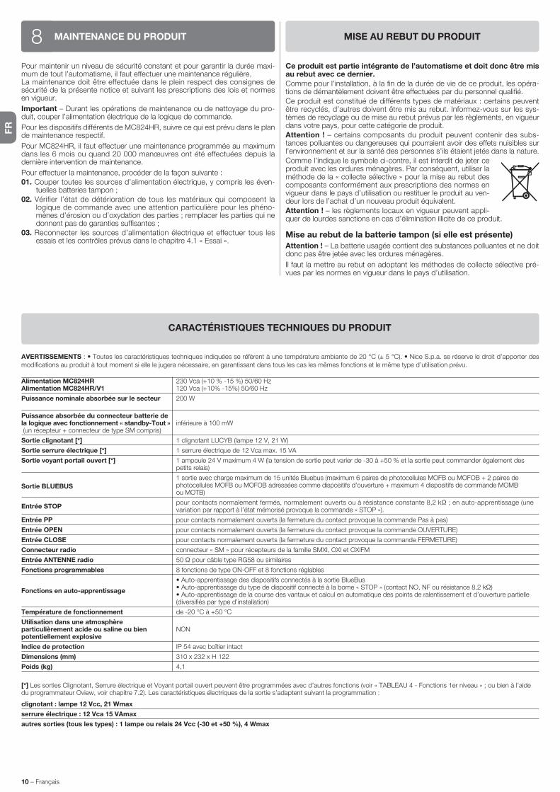
FR
10 – Français
AVERTISSEMENTS : • Toutes les caractéristiques techniques indiquées se réfèrent à une température ambiante de 20 °C (± 5 °C). • Nice S.p.a. se réserve le droit d’apporter des modifications au produit à tout moment si elle le jugera nécessaire, en garantissant dans tous les cas les mêmes fonctions et le même type d’utilisation prévu.
Alimentation MC824HR 230 Vca (+10 % -15 %) 50/60 Hz Alimentation MC824HR/V1 120 Vca (+10% -15%) 50/60 Hz
Puissance nominale absorbée sur le secteur 200 W
Puissance absorbée du connecteur batterie de la logique avec fonctionnement « standby-Tout » inférieure à 100 mW (un récepteur + connecteur de type SM compris)
Sortie clignotant [*] 1 clignotant LUCYB (lampe 12 V, 21 W)
Sortie serrure électrique [*] 1 serrure électrique de 12 Vca max. 15 VA
Sortie voyant portail ouvert [*] 1 ampoule 24 V maximum 4 W (la tension de sortie peut varier de -30 à +50 % et la sortie peut commander également des petits relais)
Sortie BLUEBUS
1 sortie avec charge maximum de 15 unités Bluebus (maximum 6 paires de photocellules MOFB ou MOFOB + 2 paires de photocellules MOFB ou MOFOB adressées comme dispositifs d’ouverture + maximum 4 dispositifs de commande MOMB ou MOTB)
Entrée STOP pour contacts normalement fermés, normalement ouverts ou à résistance constante 8,2 kΩ ; en auto-apprentissage (une
variation par rapport à l’état mémorisé provoque la commande « STOP »).
Entrée PP pour contacts normalement ouverts (la fermeture du contact provoque la commande Pas à pas)
Entrée OPEN pour contacts normalement ouverts (la fermeture du contact provoque la commande OUVERTURE)
Entrée CLOSE pour contacts normalement ouverts (la fermeture du contact provoque la commande FERMETURE)
Connecteur radio connecteur « SM » pour récepteurs de la famille SMXI, OXI et OXIFM
Entrée ANTENNE radio 50 Ω pour câble type RG58 ou similaires
Fonctions programmables 8 fonctions de type ON-OFF et 8 fonctions réglables
• Auto-apprentissage des dispositifs connectés à la sortie BlueBus
Fonctions en auto-apprentissage • Auto-apprentissage du type de dispositif connecté à la borne « STOP » (contact NO, NF ou résistance 8,2 kΩ)
• Auto-apprentissage de la course des vantaux et calcul en automatique des points de ralentissement et d’ouverture partielle (diversifiés par type d’installation)
Température de fonctionnement de -20 °C à +50 °C
Utilisation dans une atmosphère particulièrement acide ou saline ou bien NON potentiellement explosive
Indice de protection IP 54 avec boîtier intact
Dimensions (mm) 310 x 232 x H 122
Poids (kg) 4,1
[*] Les sorties Clignotant, Serrure électrique et Voyant portail ouvert peuvent être programmées avec d’autres fonctions (voir « TABLEAU 4 - Fonctions 1er niveau » ; ou bien à l’aide du programmateur Oview, voir chapitre 7.2). Les caractéristiques électriques de la sortie s’adaptent suivant la programmation :
clignotant : lampe 12 Vcc, 21 Wmax
serrure électrique : 12 Vca 15 VAmax
autres sorties (tous les types) : 1 lampe ou relais 24 Vcc (-30 et +50 %), 4 Wmax
CARACTÉRISTIQUES TECHNIQUES DU PRODUIT
MAINTENANCE DU PRODUIT8Pour maintenir un niveau de sécurité constant et pour garantir la durée maxi-mum de tout l’automatisme, il faut effectuer une maintenance régulière.La maintenance doit être effectuée dans le plein respect des consignes de sécurité de la présente notice et suivant les prescriptions des lois et normes en vigueur.
Important – Durant les opérations de maintenance ou de nettoyage du pro-duit, couper l’alimentation électrique de la logique de commande.
Pour les dispositifs différents de MC824HR, suivre ce qui est prévu dans le plan de maintenance respectif.
Pour MC824HR, il faut effectuer une maintenance programmée au maximum dans les 6 mois ou quand 20 000 manœuvres ont été effectuées depuis la dernière intervention de maintenance.
Pour effectuer la maintenance, procéder de la façon suivante :01. Couper toutes les sources d’alimentation électrique, y compris les éven-
tuelles batteries tampon ;02. Vérifier l’état de détérioration de tous les matériaux qui composent la
logique de commande avec une attention particulière pour les phéno-mènes d’érosion ou d’oxydation des parties ; remplacer les parties qui ne donnent pas de garanties suffisantes ;
03. Reconnecter les sources d’alimentation électrique et effectuer tous les essais et les contrôles prévus dans le chapitre 4.1 « Essai ».
MISE AU REBUT DU PRODUIT
Ce produit est partie intégrante de l’automatisme et doit donc être mis au rebut avec ce dernier.
Comme pour l’installation, à la fin de la durée de vie de ce produit, les opéra-tions de démantèlement doivent être effectuées par du personnel qualifié.
Ce produit est constitué de différents types de matériaux : certains peuvent être recyclés, d’autres doivent être mis au rebut. Informez-vous sur les sys-tèmes de recyclage ou de mise au rebut prévus par les règlements, en vigueur dans votre pays, pour cette catégorie de produit.
Attention ! – certains composants du produit peuvent contenir des subs-tances polluantes ou dangereuses qui pourraient avoir des effets nuisibles sur l’environnement et sur la santé des personnes s’ils étaient jetés dans la nature.
Comme l’indique le symbole ci-contre, il est interdit de jeter ce produit avec les ordures ménagères. Par conséquent, utiliser la méthode de la « collecte sélective » pour la mise au rebut des composants conformément aux prescriptions des normes en vigueur dans le pays d’utilisation ou restituer le produit au ven-deur lors de l’achat d’un nouveau produit équivalent.
Attention ! – les règlements locaux en vigueur peuvent appli-quer de lourdes sanctions en cas d’élimination illicite de ce produit.
Mise au rebut de la batterie tampon (si elle est présente)
Attention ! – La batterie usagée contient des substances polluantes et ne doit donc pas être jetée avec les ordures ménagères.
Il faut la mettre au rebut en adoptant les méthodes de collecte sélective pré-vues par les normes en vigueur dans le pays d’utilisation.

ES
Español – 1
ESPAÑOL
ÍndiceADVERTENCIAS Y PRECAUCIONES GENERALES . . . . . . . . . . . . . . . . 1Advertencias de seguridad . . . . . . . . . . . . . . . . . . . . . . . . . . . . . . . . . . . . . . 1Advertencias para la instalación . . . . . . . . . . . . . . . . . . . . . . . . . . . . . . . . . . 1Advertencias para el uso . . . . . . . . . . . . . . . . . . . . . . . . . . . . . . . . . . . . . . . 1
1 - DESCRIPCIÓN DEL PRODUCTO Y USO PREVISTO . . . . . . . . . . . . . 1
2 - INSTALACIÓN . . . . . . . . . . . . . . . . . . . . . . . . . . . . . . . . . . . . . . . . . . . . 12.1 - Controles preliminares a la instalación . . . . . . . . . . . . . . . . . . . . . . . . . 12.2 - Límites de empleo del producto . . . . . . . . . . . . . . . . . . . . . . . . . . . . . . 22.3 - Instalación típica . . . . . . . . . . . . . . . . . . . . . . . . . . . . . . . . . . . . . . . . . . 22.4 - Instalación de la central de mando . . . . . . . . . . . . . . . . . . . . . . . . . . . . 2
3 - CONEXIONES ELÉCTRICAS . . . . . . . . . . . . . . . . . . . . . . . . . . . . . . . . 23.1 - Descripción de las conexiones eléctricas . . . . . . . . . . . . . . . . . . . . . . . 23.2 - Conexiones eléctricas de la central MC824HR . . . . . . . . . . . . . . . . . . . 23.3 - Conexión de otros dispositivos a MC824HR . . . . . . . . . . . . . . . . . . . . 33.4 - Direccionamiento de los dispositivos conectados a MC824HR . . . . . . 33.5 - Primer encendido y control de las conexiones . . . . . . . . . . . . . . . . . . . 33.6 - Aprendizaje de los dispositivos conectados a MC824HR . . . . . . . . . . . 33.7 - Aprendizaje de las posiciones de los fines de carrera mecánicos . . . . . 3 3.7.1 - Aprendizaje en modo automático . . . . . . . . . . . . . . . . . . . . . . . 4 3.7.2 - Aprendizaje en modo manual . . . . . . . . . . . . . . . . . . . . . . . . . . 4 3.7.3 - Aprendizaje en modo mixto . . . . . . . . . . . . . . . . . . . . . . . . . . . . 43.8 - Control del movimiento de las hojas de la cancela . . . . . . . . . . . . . . . . 4
4 - ENSAYO Y PUESTA EN SERVICIO . . . . . . . . . . . . . . . . . . . . . . . . . . . 44.1 - Ensayo . . . . . . . . . . . . . . . . . . . . . . . . . . . . . . . . . . . . . . . . . . . . . . . . . 44.2 - Puesta en servicio . . . . . . . . . . . . . . . . . . . . . . . . . . . . . . . . . . . . . . . . 5
5 - PROGRAMACIÓN . . . . . . . . . . . . . . . . . . . . . . . . . . . . . . . . . . . . . . . . . 55.1 - Programación del primer nivel (ON-OFF) . . . . . . . . . . . . . . . . . . . . . . . 55.2 - Programación del segundo nivel (parámetros regulables) . . . . . . . . . . . 65.3 – Funciones especiales . . . . . . . . . . . . . . . . . . . . . . . . . . . . . . . . . . . . . . 75.4 - Borrado de la memoria . . . . . . . . . . . . . . . . . . . . . . . . . . . . . . . . . . . . . 7
6 - QUÉ HACER SI… (guía para solucionar los problemas) . . . . . . . . . 8
7 - OTRAS INFORMACIONES . . . . . . . . . . . . . . . . . . . . . . . . . . . . . . . . . . 97.1 - Conexión de un receptor . . . . . . . . . . . . . . . . . . . . . . . . . . . . . . . . . . . 97.2 - Conexión del programador Oview . . . . . . . . . . . . . . . . . . . . . . . . . . . . 97.3 - Conexión del sistema de energía solar Solemyo . . . . . . . . . . . . . . . . . . 97.4 - Conexión de la batería compensadora mod. PS324 . . . . . . . . . . . . . . . 9
8 - MANTENIMIENTO DEL PRODUCTO . . . . . . . . . . . . . . . . . . . . . . . . 10
ELIMINACIÓN DEL PRODUCTO . . . . . . . . . . . . . . . . . . . . . . . . . . . . . . 10
CARACTERÍSTICAS TÉCNICAS DEL PRODUCTO . . . . . . . . . . . . . . . . 10
DECLARACIÓN DE CONFORMIDAD CE . . . . . . . . . . . . . . . . . . . . . . . . . II
Instrucciones y advertencias destinadas al usuario . . . . . . . . . . . . . . VIIIImágenes . . . . . . . . . . . . . . . . . . . . . . . . . . . . . . . . . . . . . . . . . . . . . . . . . XII
MC824HR es una central electrónica indicada para automatizar cancelas y hojas batientes con motores de la serie Toona del modelo 5624I (consulte el apartado “2.2 Límites de empleo del producto”). ¡ATENCIÓN! – ¡Cualquier otro empleo que no sea aquel descrito y en condiciones ambientales diferentes de aquellas indicadas en este manual debe ser considerado inadecuado y está prohibido!La central de mando está predispuesta para ser conectada a dispositivos per-tenecientes al Sistema Opera, al sistema Bluebus y al sistema de alimentación por energía solar Solemyo.Si estuviera alimentada desde la red, puede montar una batería de compen-sación (mod. PS324, accesorio opcional) que, en caso de corte de la energía eléctrica garantiza que el automatismo pueda realizar, en las horas sucesivas, algunos movimientos.Otros accesorios disponibles son los receptores predispuestos con conexión “SM” (SMXI, OXI, etc.).
DESCRIPCIÓN DEL PRODUCTO Y USO PREVISTO1
Advertencias de seguridad• ¡ATENCIÓN! – El presente manual contiene instrucciones y adverten-
cias importantes para la seguridad de las personas. Una instalación incorrecta podría provocar heridas graves. Antes de comenzar a trabajar es ne cesario leer detenidamente todas las partes del manual. Si tuviera dudas, su spenda la instalación y solicite aclaraciones al Servicio de Asistencia de Nice.
• ¡ATENCIÓN! – Instrucciones importantes: guarde este manual para cuando deba llevar a cabo los trabajos de mantenimiento o cuando deba eliminar el producto.
• ¡ATENCIÓN! – Según la más reciente legislación europea, la ejecución de un portón o puerta automática debe cumplir las normas previstas por la Directiva 2006/42/CE (ex 98/37/CE) (Directiva de Máquinas) y, en con creto, las normas EN 12445; EN 12453; EN 12635 y EN 13241-1, que per miten declarar la conformidad del automatismo. Consideran-do lo anterior, todas las operaciones de instalación, conexión, ensa-yo y mant enimiento del producto deberán ser realizadas únicamente por un técnico cualificado y competente.
Advertencias para la instalación• Antes de comenzar la instalación, controle que el producto sea adecuado
para el tipo de uso deseado (véase el párrafo 2.2 “Límites de empleo” y las “Características técnicas del producto”). Si no fuera adecuado, NO lo instale.
• El contenido de este manual se refiere a un sistema típico como aquel que se muestra en la fig. 2a.
• Todas las operaciones de instalación y mantenimiento deben efec-tuarse con el automatismo desconectado de la alimentación eléc-trica. Si el dispositivo de desconexión de la alimentación no resulta visible desde el lugar en el que está situado el automatismo, antes de comenzar los trabajos es necesario fijar al dispositivo de desconexión un cartel con el mensaje “¡ATENCIÓN! MANTENIMIENTO EN CURSO”.
• Monte en la red de alimentación de la instalación un dispositivo de desconexión con una distancia de apertura de los contactos que permita la desconexión completa de las condiciones establecidas para la categoría III de sobretensión.
• Conecte la central a una línea de alimentación eléctrica equipada con puesta a tierra de seguridad.
• Durante la instalación manipule con cuidado el producto, evitando aplasta-mientos, golpes, caídas o contacto con líquidos de cualquier tipo. No colo-que el producto cerca de fuentes de calor ni lo exponga al fuego. Esto podría averiarlo y provocar desperfectos de funcionamiento o situaciones peligro-sas. Si así fuera, suspenda inmediatamente la instalación y contacte con el Servicio de Asistencia Nice.
• No modifique ninguna pieza del producto. Las operaciones no permitidas pueden provocar desperfectos de funcionamiento. El fabricante no se asu-mirá ninguna responsabilidad por daños originados por modificaciones arbi-trarias hechas al producto.
• El material de embalaje del producto debe eliminarse respetando la normati-va local.
Advertencias para el uso• El producto no está destinado para ser utilizado por personas (niños inclui-
dos) cuyas capacidades físicas, sensoriales o mentales sean reducidas, o sin experiencia ni conocimientos, salvo que dichas personas estén acompaña-das por una persona responsable de su seguridad o hayan sido instruidas sobre el uso del producto.
• Controle que los niños que estén cerca no jueguen con el automatismo.• No permita que los niños jueguen con los dispositivos de mando fijos. Manten-
ga los dispositivos de mando portátiles (remotos) fuera del alcance de los niños.
ADVERTENCIAS Y PRECAUCIONES GENERALES
2.1 - Controles preliminares a la instalación
Antes de proceder con la instalación, controle la integridad de los componen-tes del producto, que el modelo corresponda con el pedido y que sea idóneo para el entorno en el cual deberá ser instalado:
INSTALACIÓN2

ES
2 – Español
CONEXIONES ELÉCTRICAS3La conexión eléctrica de los distintos dispositivos (fotocélulas, botoneras digi-tales, lectores de tarjetas por transponder, etc.), presentes en el automatismo con la central de mando, debe hacerse mediante el sistema “Bluebus” de Nice.
3.1 - Descripción de las conexiones eléctricas (fig. 6)
ANTENA entrada para la antena de un receptor
FLASH salida para una luz intermitente con bombilla de 12 V (máximo 21 W). [*]
ELS salida para electrocerradura de 12 Vac (máximo 15 VA). [*]
S.C.A. “Indicador Cancela Abierta”: salida para una bombilla de señaliza-ción de 24V y 4W como máximo. [*]
BLUEBUS entrada para dispositivos compatibles (MOFB, MOFOB, MOB y MOTB); conexión en paralelo de los dispositivos mediante 2 conduc-tores por los cuales pasa la alimentación eléctrica y las señales de comunicación; no hay que respetar ninguna polaridad. La conexión eléctrica a utilizar es paralela y no necesita respetar la polaridad. Durante la etapa de aprendizaje, cada dispositivo conectado a la central será reconocido individualmente por ésta gracias a un código unívoco. Cada vez que se añada o elimine un dispositivo, habrá que hacer que la central memorice dicho dispositivo (véase el párrafo 3.6).
STOP entrada para los dispositivos que al accionarse provocan la parada inmediata del movimiento que se está ejecutando en ese momento, seguido de una breve inversión; posibilidad de conectar contactos NA, NC o bien dispositivos con salida con resistencia constan-te 8,2 kΩ (bandas sensibles). Cada dispositivo conectado a esta entrada será reconocido individualmente por la central durante el aprendizaje (párrafo 3.6); en esta etapa, si la central detectara una variación respecto del estado memorizado, provocará una PARADA. A esta entrada se le pueden conectar uno o varios dispositivos incluso diferentes entre sí:
– conecte en paralelo varios dispositivos NA, sin límites de cantidad; – conexión en serie de varios dispositivos NC, sin límite de cantidad; – conecte en paralelo dos dispositivos con salida de resistencia
constante 8,2 kΩ. Si hubiera más de dos dispositivos, habrá que conectarlos en cascada a una sola resistencia de termina-ción de 8,2 kΩ;
– conecte en paralelo dos dispositivos NA y NC, colocando una resistencia de 8,2 kΩ en serie al contacto NC (esto permite la combinación entre tres dispositivos NA - NC y 8,2 kΩ).
P.P. entrada para los dispositivos de mando que al activarse provocan el movimiento con modalidad Paso a Paso; posibilidad de conectar contactos tipo NA.
OPEN entrada para los dispositivos de mando que al activarse provocan sólo el movimiento de apertura; posibilidad de conectar contactos tipo NA
CLOSE entrada para los dispositivos de mando que al activarse provocan sólo el movimiento de cierre; posibilidad de conectar contactos tipo NA
ENC1 entrada encoder - motorreductor 1 (bornes 1, 2); no hay que res-petar ninguna polaridad
ENC2 entrada encoder - motorreductor 2 (bornes 4, 5); no hay que res-petar ninguna polaridad
M1 salida para motorreductor 1 (bornes 7, 8, 9)
M2 salida para motorreductor 2 (bornes 10, 11, 12).
[*] Las salidas FLASH, ELS y S.C.A. pueden programarse con otras funciones (véase la “TABLA 4 – Funciones de 1° nivel”; o bien mediante el programador Oview, véase el capítulo 7.2).
3.2 - Conexiones eléctricas de la central MC824HR
Fije la caja de la central, prepare los agujeros para el paso de los cables eléc-tricos (cap. 2.4 y fig. 3) y, posteriormente, realice las conexiones eléctricas:
¡ATENCIÓN!– Todas las conexiones eléctricas deben hacerse con la corriente eléc-trica de red desactivada y con la batería compensadora desconectada, si estuviera presente en el automatismo.
• Controle que todo el material a utilizar esté en perfectas condiciones y sea adecuado para el uso previsto.
• Controle que todas las condiciones de uso estén dentro de los límites de empleo del producto (párrafo 2.2) y dentro de los límites de los valores indi-cados en las “Características técnicas del producto”.
• Controle que el entorno escogido para la instalación sea compatible con las medidas totales del producto (véase la fig. 1).
• Controle que la superficie escogida para la instalación del producto sea sóli-da y que pueda garantizar una fijación estable.
• Controle que la zona de fijación no pueda inundarse; prevea el montaje del producto levantado del suelo.
• Controle que el espacio de alrededor del producto permita una acceso fácil y seguro.
• Controle que todos los cables eléctricos que deba utilizar correspondan con el tipo de cable mencionado en la Tabla 1.
• Controle que en el automatismo se encuentren los topes mecánicos de cie-rre y de apertura.
2.2 - Límites de empleo del producto
La central MC824HR se puede utilizar exclusivamente con los motorreductores Toona del modelo 5624I; estos motores son reversibles, es decir, es posible mover manualmente las hojas de la cancela sin tener que desbloquear el moto-rreductor manualmente. Gracias al sensor que incorpora el motor, la central puede detectar el movimiento manual de las hojas y, además, gestionar correc-tamente las maniobras posteriores. De esta forma, se impide que las hojas cho-quen contra los topes mecánicos de apertura y cierre. ¡Atención! - No se detec-tará el movimiento de las hojas en caso de que la central no reciba alimentación correctamente o bien si está activada la función “Todo en stand by”.
2.3 - Instalación típica
En la fig. 2a se muestra un ejemplo de una instalación de automatización rea-lizada con componentes Nice:a - Central de mando
b - Motorreductorc - Luz intermitented - Fotocélulae - Botonera digital - Lector por transponder - Selector de llavef - Columna para fotocélulag - Topes mecánicos de aperturah - Tope mecánico de cierrei - Electrocerradura
Estos componentes están colocados según un esquema típico y habitual. Tomando como referencia la fig. 2a, establezca la posición aproximada don-de será instalado cada uno de los componentes previstos en la instalación. Importante – Antes de realizar la instalación, prepare los cables eléctricos necesarios, tomando como referencia la fig. 2b y la “Tabla 1 – Característi-cas técnicas de los cables eléctricos”.
Atención – Durante la colocación de los tubos para el paso de los cables eléc-tricos y la entrada de los cables en la caja de la central, tenga en cuenta que por motivos de los depósitos de agua que se podrían formar en las arquetas de derivación, los tubos de conexión podrían crear fenómenos de condensa-ción en el interior de la central, lo cual podría averiar los circuitos electrónicos.
2.4 - Instalación de la central de mando
Para fijar la central de mando, proceda como se muestra en la fig. 3:01. Desenrosque los tornillos y abra la caja de la central (fig. 3-A);02. Prepare los agujeros para pasar los cables eléctricos (fig. 3-B);03. Fije la caja (fig. 3-C);04. Entonces será posible realizar las conexiones eléctricas: véase el cap. 3.¡Atención! – Para preparar la entrada de los tubos para los cables eléctricos es necesario taladrar el lado inferior de la caja de la central. Nota – Si fuera necesario, es posible utilizar la entrada lateral para los cables, pero únicamente utilizando los racores adecuados para tubos.Para instalar los demás dispositivos presentes en la automatización, consulte los manuales de instrucción respectivos.
Conexión Tipo de cable Longitud máxima admitida
A: Cable ALIMENTACIÓN CENTRAL DE MANDO 1 cable 3 x 1,5 mm2 30 m (nota 1)
B: Cable LUZ INTERMITENTE con antena 1 cable 2 x 0,5 mm2 20 m 1 cable blindado tipo RG58 20 m (aconsejado menos de 5 m)
C: Cable DISPOSITIVOS BLUEBUS 1 cable 2 x 0,5 mm2 20 m (nota 2)
D: Cable SELECTOR DE LLAVE 2 cables 2 x 0,5 mm2 (nota 3) 50 m
E: Cable ALIMENTACIÓN MOTORREDUCTOR 1 cable 3 x 1,5 mm2 (nota 4) 10 m
F: Cable CONEXIÓN ENCODER 1 cable 2 x 1 mm2 (nota 4) 10 m
G: Cable CONEXIÓN ELECTROCERRADURA 1 cable 2 x 1 mm2 10 m
Nota 1 – Si el cable de alimentación midiera más de 30 m, tendrá que utilizar un cable de sección más grande (3 x 2,5 mm2) y habrá que instalar una puesta a tierra de seguridad cerca de la automatización.Nota 2 – Si el cable Bluebus midiera más de 20 m hasta un máximo de 40 m, tendrá que utilizar un cable de sección más grande (2 x 1 mm2).Nota 3 – Estos 2 cables pueden sustituirse por un único cable de 4 x 0,5 mm2.Nota 4 – Estos cables pueden sustituirse por un único cable de 5 x 1,5 mm2.
¡ATENCIÓN – Los cables utilizados deben ser adecuados para el tipo de entorno donde serán instalados.
TABLA 1 - Características técnicas de los cables eléctricos (fig. 2b)

ES
Español – 3
3.5 - Primer encendido y control de las conexiones
Después de haber conectado la energía eléctrica de la Central de mando, lleve a cabo los siguientes controles:• transcurridos algunos segundos, compruebe que el Led “Bluebus” (fig. 7)
destelle regularmente con una frecuencia de 1 destello por segundo;• controle que destellen los Leds de las fotocélulas (fig. 7), tanto TX (transmi-
sor) como RX (receptor). En esta etapa, el tipo de destello no es importante;• controle que la luz intermitente conectada a la salida FLASH esté apagada.
Si así no fuera, habrá que cortar la energía eléctrica de la central y controlar las conexiones eléctricas hechas.
3.6 - Aprendizaje de los dispositivos conectados a MC824HR
Después de haber realizado el primer encendido, es necesario que la central reconozca los dispositivos conectados en las entradas “Bluebus” y “Stop”.
¡ATENCIÓN! – El aprendizaje debe hacerse incluso si no hubiera ningún dispositivo conectado a la central.
La central reconoce individualmente los dispositivos conectados gracias al procedimiento de aprendizaje y detecta con mucha precisión los posibles des-perfectos presentes. Por dicho motivo, es necesario realizar el aprendizaje de los dispositivos cada vez que uno de estos es añadido o eliminado.Los Leds “L1” y “L2” presentes en la central (fig. 7) emiten algunos destellos lentos que indican que es necesario llevar a cabo el aprendizaje:01. Pulse y mantenga pulsados simultáneamente los pulsadores “ ” y “Set”
(fig. 7).02. Suelte los pulsadores cuando los leds “L1” y “L2” comiencen a destellar
rápidamente (después de unos 3 segundos).03. Espere algunos segundos para que la central complete el aprendizaje de
los dispositivos.04. Al concluir esta etapa, el Led “Stop” deberá estar encendido y los Leds “L1”
y “L2” se deberán apagar (podrían comenzar a destellar los Leds “L3” y “L4”).
3.7 - Aprendizaje de las posiciones de los fines de carrera mecánicos
Después del aprendizaje de los dispositivos conectados (párrafo 3.6) habrá que realizar el aprendizaje de las posiciones de los topes mecánicos (apertura máxima y cierre máximo). Este procedimiento se puede realizar en tres modos: automático, manual y mixto.En el modo automático, la central ejecuta el aprendizaje de los topes mecá-nicos y calcula la sincronización más oportuna de las hojas (SA y SC, fig. B).En el modo manual, las ocho posiciones de los topes mecánicos (fig. B) se programan una por una, desplazando las hojas hacia los puntos deseados. La posición que se debe programar está identificada por el destello de uno de los 8 leds (L1...L8), véase la Tabla 3.En el modo mixto, es posible llevar a cabo el procedimiento automático y, pos-teriormente, con el procedimiento manual, modificar una o varias posiciones salvo las posiciones “0” y “1” (fig. B) que coinciden con las posiciones de los topes mecánicos.
– Las operaciones de conexión deben ser realizadas exclusivamente por personal cualificado.– En la línea eléctrica de alimentación es necesario montar un dispositivo que asegure la desconexión completa del automatismo de la red. El dispositivo de desconexión deberá tener una distancia de apertura entre los contactos que permita una desconexión completa en las condiciones previstas por la catego-ría de sobretensión III, de conformidad con las reglas de instalación. Si fuera necesario, este dispositivo deberá garantizar una desconexión rápida y segura de la alimentación; por dicho motivo, debe estar a la vista del automatismo. Por el contrario, si se montara en una posición no visible, deberá tener un siste-ma que bloquee una reconexión accidental o no autorizada de la alimentación, a fin de evitar cualquier tipo de peligro. El dispositivo de desconexión no se entrega junto con el producto.
01. Conecte primero el cable de alimentación eléctrica (fig. 4) y bloquéelo con el prensaestopas;
02. Ahora conecte los cables eléctricos de los motores M1 y M2, respetando los símbolos de la etiqueta (fig. 5):
a) conecte al borne M1 el motor que acciona la hoja inferior (la segunda que comienza el movimiento de apertura) y, posteriormente, conecte el encoder respectivo a los bornes 1-2;
b) conecte al borne M2 el motor que acciona la hoja superior (la primera que comienza el movimiento de apertura) y, posteriormente, conecte el encoder respectivo a los bornes 4-5
¡IMPORTANTE! – Si en el sistema hubiera un solo motorreductor, conéctelo al borne M2 dejando libre el borne M1;
03. Entonces, conecte los cables eléctricos de los demás dispositivos presen-tes, tomando como referencia la fig. 6 y véase el párrafo 3.3. Nota – Para facilitar las conexiones de los cables es posible quitar los bornes de sus alojamientos.
3.3 - Conexión de otros dispositivos a MC824HR
Si fuera necesario alimentar otros dispositivos montados en la instalación, por ej emplo un lector de tarjetas de transponder o la luz de iluminación para el se lector de llave, es posible conectar estos dispositivos a la central de mando en los bornes “P.P. (positivo)” y “STOP (negativo)” (fig. 6). La tensión de alimenta-ción es de 24 Vcc (-30% ÷ +50%) con corriente máxima disponible de 200 mA.Nota – La tensión disponible en los bornes “P.P.” y “STOP” siempre está pre-sente cuando en la tarjeta se activa la función “Stand By”.
3.4 - Direccionamiento de los dispositivos conectados a MC824HR
Para que la central pueda reconocer los dispositivos conectados al sistema Bluebus, es necesario asignarles una dirección. Esta operación debe hacerse colocando correctamente el puente eléctrico presente en todos los dispositivos, véase el manual de instrucciones de cada dispositivo: véanse fig. A y Tabla 2.Al concluir la instalación o después de haber desmontado las fotocélulas o cualquier otro dispositivo, habrá que realizar el aprendizaje de estos últimos; véase el párrafo 3.6.
A
TABLA 2 - DIRECCIONES DE LAS FOTOCÉLULAS
Fotocélula Puentes de conexión
FOTO Fotocélula exterior h = 50 con activación durante el cierre (detiene e invierte el movimiento)
FOTO II Fotocélula exterior h = 100 con activación durante el cierre (detiene e invierte el movimiento)
FOTO 1 Fotocélula interior h = 50 con activación durante el cierre (detiene e invierte el movimiento) y durante la apertura (detiene y reanuda el movimiento al descubrirse la fotocélula)
FOTO 1 II Fotocélula interior h = 100 con activación durante el cierre (detiene e invierte el movimiento) y durante la apertura (detiene y reanuda el movimiento aldescubrirse la fotocélula)
FOTO 2 Fotocélula interior con activación durante la apertura (detiene e invierte el movimiento)
FOTO 2 II Fotocélula interior con activación durante la apertura (detiene e invierte el movimiento)
FOTO 3 CONFIGURACIÓN NO ADMITIDA
0
1 1A
SC
SA
A
0M1 M2
B POSICIONES
TABLA 3
Posición Led Descripción
Posición 0(motor 1)
Posición 0(motor 2)
Posición SA(motor 2)
Posición A(motor 1)
Posición A(motor 2)
Posición SC(motor 1)
Posición 1(motor 1)
Posición 1(motor 2)
Posición de cierre máximo: cuando la hoja 1 choca contra el tope mecánico de cierre
Posición de cierre máximo: cuando la hoja 2 choca contra el tope mecánico de cierre
Sincronización en la apertura: cuando la hoja 2 supera esta posición, la hoja 1 comienza a abrirse
Posición de apertura deseada: posición en que la hoja conec-tada al motor 1 debe detenerse al concluir un movimiento de apertura. No es necesario que esta posición coincida con el tope mecánico de apertura sino que puede seleccionarse a placer entre la posición “0” y “1”
Posición de apertura deseada: posición en que la hoja conec-tada al motor 2 debe detenerse al concluir un movimiento de apertura. No es necesario que esta posición coincida con el tope mecánico de apertura sino que puede seleccionarse a placer entre la posición “0” y “1”
Sincronización en el cierre: cuando la hoja 1 se encuentra por debajo de esta posición, la hoja 2 comienza a cerrarse
Posición de apertura máxima: cuando la hoja 1 choca contra el tope mecánico de apertura
Posición de apertura máxima: cuando la hoja 2 choca contra el tope mecánico de apertura
L1
L2
L3
L4
L5
L6
L7
L8
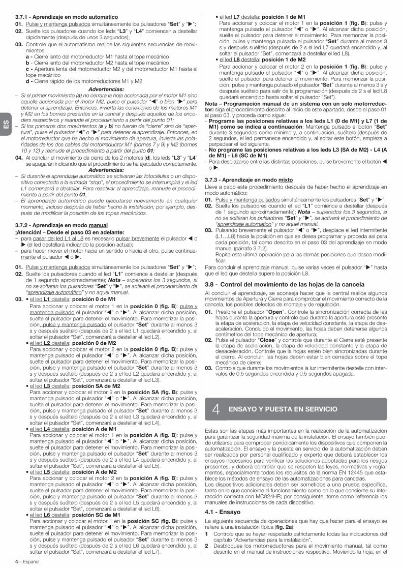
ES
4 – Español
3.7.1 - Aprendizaje en modo automático
01. Pulse y mantenga pulsados simultáneamente los pulsadores “Set” y “ ”;
02. Suelte los pulsadores cuando los leds “L3” y “L4” comiencen a destellar rápidamente (después de unos 3 segundos);
03. Controle que el automatismo realice las siguientes secuencias de movi-mientos:
a - Cierre lento del motorreductor M1 hasta el tope mecánico b - Cierre lento del motorreductor M2 hasta el tope mecánico c - Apertura lenta del motorreductor M2 y del motorreductor M1 hasta el
tope mecánico d - Cierre rápido de los motorreductores M1 y M2
Advertencias:– Si el primer movimiento (a) no cerrara la hoja accionada por el motor M1 sino
aquella accionada por el motor M2, pulse el pulsador “ ” o bien “ ” para detener el aprendizaje. Entonces, invierta las conexiones de los motores M1 y M2 en los bornes presentes en la central y después aquellos de los enco-ders respectivos y reanude el procedimiento a partir del punto 01;
– Si los primeros dos movimientos (a y b) no fueran de “cierre” sino de “aper-tura”, pulse el pulsador “ ” o “ ” para detener el aprendizaje. Entonces, en el motorreductor que ha hecho el movimiento de apertura, invierta las pola-ridades de los dos cables del motorreductor M1 (bornes 7 y 9) y M2 (bornes 10 y 12) y reanude el procedimiento a partir del punto 01;
04. Al concluir el movimiento de cierre de los 2 motores (d), los leds “L3” y “L4” se apagarán indicando que el procedimiento se ha ejecutado correctamente.
Advertencias:– Si durante el aprendizaje automático se activaran las fotocélulas o un dispo-
sitivo conectado a la entrada “stop”, el procedimiento se interrumpirá y el led L1 comenzará a destellar. Para reactivar el aprendizaje, reanude el procedi-miento a partir del punto 01;
– El aprendizaje automático puede ejecutarse nuevamente en cualquier momento, incluso después de haber hecho la instalación; por ejemplo, des-pués de modificar la posición de los topes mecánicos.
3.7.2 - Aprendizaje en modo manual
¡Atención! – Desde el paso 03 en adelante:– para pasar del led L1 al L8 es necesario pulsar brevemente el pulsador o
(el led destellará indicando la posición actual);– para hacer mover el motor hacia un sentido o hacia el otro, pulse continua-
mente el pulsador o .
01. Pulse y mantenga pulsados simultáneamente los pulsadores “Set” y “ ”;
02. Suelte los pulsadores cuando el led “L1” comience a destellar (después de 1 segundo aproximadamente); Nota – superados los 3 segundos, si no se soltaran los pulsadores “Set” y “ ”, se activará el procedimiento de “aprendizaje automático” y no aquel manual.
03. • el led L1 destella: posición 0 de M1
Para accionar y colocar el motor 1 en la posición 0 (fig. B): pulse y mantenga pulsado el pulsador “ ” o “ ”. Al alcanzar dicha posición, suelte el pulsador para detener el movimiento. Para memorizar la posi-ción, pulse y mantenga pulsado el pulsador “Set” durante al menos 3 s y después suéltelo (después de 2 s el led L1 quedará encendido y, al soltar el pulsador “Set”, comenzará a destellar el led L2).
• el led L2 destella: posición 0 de M2 Para accionar y colocar el motor 2 en la posición 0 (fig. B): pulse y
mantenga pulsado el pulsador “ ” o “ ”. Al alcanzar dicha posición, suelte el pulsador para detener el movimiento. Para memorizar la posi-ción, pulse y mantenga pulsado el pulsador “Set” durante al menos 3 s y después suéltelo (después de 2 s el led L2 quedará encendido y, al soltar el pulsador “Set”, comenzará a destellar el led L3).
• el led L3 destella: posición SA de M2 Para accionar y colocar el motor 2 en la posición SA (fig. B): pulse y
mantenga pulsado el pulsador “ ” o “ ”. Al alcanzar dicha posición, suelte el pulsador para detener el movimiento. Para memorizar la posi-ción, pulse y mantenga pulsado el pulsador “Set” durante al menos 3 s y después suéltelo (después de 2 s el led L3 quedará encendido y, al soltar el pulsador “Set”, comenzará a destellar el led L4).
• el led L4 destella: posición A de M1 Para accionar y colocar el motor 1 en la posición A (fig. B): pulse y
mantenga pulsado el pulsador “ ” o “ ”. Al alcanzar dicha posición, suelte el pulsador para detener el movimiento. Para memorizar la posi-ción, pulse y mantenga pulsado el pulsador “Set” durante al menos 3 s y después suéltelo (después de 2 s el led L4 quedará encendido y, al soltar el pulsador “Set”, comenzará a destellar el led L5).
• el led L5 destella: posición A de M2 Para accionar y colocar el motor 2 en la posición A (fig. B): pulse y
mantenga pulsado el pulsador “ ” o “ ”. Al alcanzar dicha posición, suelte el pulsador para detener el movimiento. Para memorizar la posi-ción, pulse y mantenga pulsado el pulsador “Set” durante al menos 3 s y después suéltelo (después de 2 s el led L5 quedará encendido y, al soltar el pulsador “Set”, comenzará a destellar el led L6).
• el led L6 destella: posición SC de M1 Para accionar y colocar el motor 1 en la posición SC (fig. B): pulse y
mantenga pulsado el pulsador “ ” o “ ”. Al alcanzar dicha posición, suelte el pulsador para detener el movimiento. Para memorizar la posi-ción, pulse y mantenga pulsado el pulsador “Set” durante al menos 3 s y después suéltelo (después de 2 s el led L6 quedará encendido y, al soltar el pulsador “Set”, comenzará a destellar el led L7).
Estas son las etapas más importantes en la realización de la automatización para garantizar la seguridad máxima de la instalación. El ensayo también pue-de utilizarse para comprobar periódicamente los dispositivos que componen la automatización. El ensayo y la puesta en servicio de la automatización deben ser realizados por personal cualificado y experto que deberá establecer los ensayos necesarios para verificar las soluciones adoptadas para los riesgos presentes, y deberá controlar que se respeten las leyes, normativas y regla-mentos, especialmente todos los requisitos de la norma EN 12445 que esta-blece los métodos de ensayo de las automatizaciones para cancelas.Los dispositivos adicionales deben ser sometidos a una prueba específica, tanto en lo que concierne el funcionamiento como en lo que concierne su inte-racción correcta con MC824HR; por consiguiente, tome como referencia los manuales de instrucciones de cada dispositivo.
4.1 - Ensayo
La siguiente secuencia de operaciones que hay que hacer para el ensayo se refiere a una instalación típica (fig. 2a):
1 Controle que se hayan respetado estrictamente todas las indicaciones del capítulo “Advertencias para la instalación”.
2 Desbloquee los motorreductores para el movimiento manual, tal como descrito en el manual de instrucciones respectivo. Moviendo la hoja, en el
ENSAYO Y PUESTA EN SERVICIO4
• el led L7 destella: posición 1 de M1 Para accionar y colocar el motor 1 en la posición 1 (fig. B): pulse y
mantenga pulsado el pulsador “ ” o “ ”. Al alcanzar dicha posición, suelte el pulsador para detener el movimiento. Para memorizar la posi-ción, pulse y mantenga pulsado el pulsador “Set” durante al menos 3 s y después suéltelo (después de 2 s el led L7 quedará encendido y, al soltar el pulsador “Set”, comenzará a destellar el led L8).
• el led L8 destella: posición 1 de M2
Para accionar y colocar el motor 2 en la posición 1 (fig. B): pulse y mantenga pulsado el pulsador “ ” o “ ”. Al alcanzar dicha posición, suelte el pulsador para detener el movimiento. Para memorizar la posi-ción, pulse y mantenga pulsado el pulsador “Set” durante al menos 3 s y después suéltelo para salir de la programación (después de 2 s el led L8 quedará encendido hasta soltar el pulsador “Set”).
Nota – Programación manual de un sistema con un solo motorreduc-tor: siga el procedimiento descrito al inicio de este apartado, desde el paso 01 al paso 03, y proceda como sigue:- Programe las posiciones relativas a los leds L1 (0 de M1) y L7 (1 de
M1) como se indica a continuación: Mantenga pulsado el botón “Set” durante 3 segundos como mínimo y, a continuación, suéltelo (después de 2 segundos, el led permanece encendido y, al soltar este botón, empieza a parpadear el led siguiente.
- No programe las posiciones relativas a los leds L3 (SA de M2) - L4 (A de M1) - L6 (SC de M1)
- Para desplazarse entre las distintas posiciones, pulse brevemente el botón o .
3.7.3 - Aprendizaje en modo mixto
Lleve a cabo este procedimiento después de haber hecho el aprendizaje en modo automático:01. Pulse y mantenga pulsados simultáneamente los pulsadores “Set” y “ ”;02. Suelte los pulsadores cuando el led “L1” comience a destellar (después
de 1 segundo aproximadamente); Nota – superados los 3 segundos, si no se soltaran los pulsadores “Set” y “ ”, se activará el procedimiento de “aprendizaje automático” y no aquel manual.
03. Pulsando brevemente el pulsador “ ” o “ ”, desplace el led intermitente (L1…L8) hacia la posición en que se desea programar y proceda así para cada posición, tal como descrito en el paso 03 del aprendizaje en modo manual (párrafo 3.7.2).
Repita esta última operación para las demás posiciones que desea modi-ficar.
Para concluir el aprendizaje manual, pulse varias veces el pulsador “ ” hasta que el led que destella supere la posición L8.
3.8 - Control del movimiento de las hojas de la cancela
Al concluir el aprendizaje, se aconseja hacer que la central realice algunos movimientos de Apertura y Cierre para comprobar el movimiento correcto de la cancela, los posibles defectos de montaje y de regulación.
01. Presione el pulsador “Open”. Controle la sincronización correcta de las hojas durante la apertura y controle que durante la apertura esté presente la etapa de aceleración, la etapa de velocidad constante, la etapa de des-aceleración. Concluido el movimiento, las hojas deben detenerse algunos centímetros del tope mecánico de apertura;
02. Pulse el pulsador “Close” y controle que durante el Cierre esté presente la etapa de aceleración, la etapa de velocidad constante y la etapa de desaceleración. Controle que la hojas estén bien sincronizadas durante el cierre. Al concluir, las hojas deben estar bien cerradas sobre el tope mecánico de cierre;
03. Controle que durante los movimientos la luz intermitente destelle con inter-valos de 0,5 segundos encendida y 0,5 segundos apagada.

ES
Español – 5
En la central hay 3 pulsadores OPEN ( ), STOP (SET), CLOSE ( ) que se pueden utilizar para accionar la central durante las etapas de prueba y para la programación de las funciones disponibles.Las funciones programables disponibles están dispuestas en 2 niveles y su estado de funcionamiento es señalado por los 8 leds (L1 ... L8) presentes en la central (led encendido = función activa; led apagado = función desactivada).
Utilice los pulsadores de programación:
OPEN ( ): – pulsador para accionar la apertura de la cancela; – pulsador de selección durante la programación.STOP/SET: pulsador que permite detener un movimiento; al pulsarlo durante más de 5 segundos, permite entrar en programación.CLOSE ( ): – pulsador para accionar el Cierre de la cancela; – pulsador de selección durante la programación.
5.1 - Programación del primer nivel (ON-OFF)
Todas las funciones del primer nivel vienen programadas de fábrica con el valor “OFF”, salvo la función “Cerrar siempre”, cuya configuración de fábrica es “ON”. Las funciones pueden modificarse en cualquier momento. Para verificar las distintas funciones, consulte la Tabla 4. Consulte la Tabla 5 para conocer el procedimiento de programación.
IMPORTANTE – El procedimiento de programación dura 10 segundos como máximo que transcurre entre la presión de un pulsador y el otro. Concluido dicho tiempo, el procedimiento finaliza automáticamente memorizando las modificaciones hechas hasta ese momento.
PROGRAMACIÓN5punto previsto para el movimiento manual, controle que sea posible abrir y cerrar las hojas con una fuerza inferior a 390 N.
3 Bloquee los motorreductores (véase el manual de instrucciones respectivo).4 Utilizando los dispositivos de mando (transmisor, pulsador de mando,
selector de llave, etc.), realice algunas pruebas de apertura, cierre y parada de la cancela, comprobando que el movimiento de las hojas corresponda a aquello previsto. Conviene hacer varios ensayos para evaluar el movimiento de las hojas y comprobar los posibles defectos de montaje o de regulación, así como la presencia de puntos de fricción.
5 Controle uno por uno el funcionamiento correcto de todos los dispositivos de seguridad incorporados en la instalación (fotocélulas, bandas sensibles, etc.). Cuando un dispositivo se acciona, el led “BLUEBUS”, presente en la Central, emi-te 2 destellos más rápidos, confirmando que el reconocimiento se ha realizado.
6 Si las situaciones peligrosas causadas por el movimiento de las hojas se han prevenido limitando la fuerza de impacto, habrá que medir la fuerza de acuerdo con lo previsto por la norma EN 12445. Si el control de la “fuerza del motorreductor” se utilizara como una ayuda del sistema para reducir la fuer-za de impacto, pruebe y busque la regulación que dé los mejores resultados.
4.2 - Puesta en servicio
La puesta en servicio puede llevarse a cabo sólo después de haber realizado correctamente todas las etapas de ensayo.
1 Realice el expediente técnico de la automatización que deberá incluir los si gui entes documentos: un dibujo de conjunto de la automatización, el es que ma de las conexiones eléctricas hechas, el análisis de los riesgos presentes y so lu ciones adoptadas, la declaración de conformidad del fabri-cante de todos los di spositivos utilizados y la declaración de conformidad cumplimentada por el instalador.
2 Aplique en la cancela una placa con los siguientes datos: tipo de automa-tización, nombre y dirección del fabricante (responsable de la “puesta en servicio”), número de matrícula, año de fabricación y marcado “CE”.
3 Cumplimente y entregue al dueño del automatismo la declaración de con-formidad de la automatización.
4 Cumplimente y entregue al dueño del automatismo el “Manual para el uso” de la automatización.
5 Cumplimente y entregue al dueño del automatismo el “Plan de manteni-miento” con las prescripciones sobre el mantenimiento de todos los dis-positivos de la automatización.
6 Antes de poner en servicio el automatismo, informe adecuadamente al dueño sobre los peligros y riesgos residuales presentes.
Para toda la documentación mencionada, Nice pone a disposición, a través de su servicio de asistencia técnica: manuales de instrucciones, guías y for-mularios preimpresos. Véase también en: www.nice-service.com
TABLA 4 - Funciones de primer nivel
Led Función Descripción
L1 Cierre automático
L2 Volver a cerrar después fotocélula
L3 Cerrar siempre (*)
L4 Stand by (Bluebus)
L5 Electrocerradura / Luz de cortesía
L6 Destello previo
L7 “Cerrar” se convierte en “Abrir parcial 1”
L8 Automático 1
Función ACTIVA: después de un movimiento de apertura se ejecuta una pausa (equivalente al Tiempo de pausa programado), transcurrida la cual, la central inicia automáticamente un movimiento de cierre. El valor de fábrica del Tiempo de pausa equivale a 30 segundos.
Función DESACTIVADA: el funcionamiento es “semiautomático”.
Función ACTIVA: si durante el movimiento de Apertura o cierre intervienen las fotocélulas, el tiempo de pausa disminuye a 5 seg. independientemente del “tiempo pausa” programado.
Con el “cierre automático” desactivado, si durante el Cierre se activarán las fotocélulas, se activará el “cierre automático” con el “tiempo pausa” programado.
Función ACTIVA: si se produjera un corte de energía, incluso breve, al volver la corriente eléctrica la cen-tral detectará la cancela abierta y, automáticamente, activará un movimiento de Cierre, antecedido de 5 seg. de destello previo.
Función DESACTIVADA: al volver la corriente eléctrica la cancela no se moverá.
Función ACTIVA: después de 1 minuto a partir del final del movimiento, la central apagará la salida “Bluebus” (dispositivos conectados) y todos los leds, salvo el led Bluebus que destellará más lentamente. Cuando la central recibe un mando, restablece el funcionamiento normal (con un breve retardo). Esta función tiene la finalidad de reducir los consumos que es muy importante con la alimentación con baterías o paneles fotovoltaicos.
Función ACTIVA: la salida “electrocerradura” conmuta su funcionamiento en “luz de cortesía”.
Función DESACTIVADA: la salida funciona como electrocerradura.
Función ACTIVA: es posible añadir una pausa de 3 segundos entre el encendido de la luz intermitente y el inicio del movimiento para advertir anticipadamente una situación peligrosa.
Función DESACTIVADA: la señal de la luz intermitente coincide con el inicio del movimiento.
Función ACTIVA: la entrada “Close” de la central conmuta su funcionamiento en “Abrir Parcial 1”.
Función ACTIVADA: con la cancela abierta y la función “Cierre automático” activada, durante el período de pausa se desactivan los comandos procedentes de las entradas y del receptor de radio. El funciona-miento de estos comandos se restablece al finalizar el período de pausa, justo después de que se inicie la maniobra de cierre.
Función DESACTIVADA: los comandos funcionan también durante el período de pausa.
(*) Función activada de fábrica
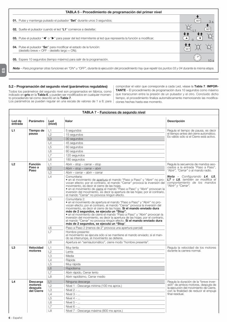
ES
6 – Español
TABLA 7 - Funciones de segundo nivel
Led de Parámetro Led Valor Descripción entrada (nivel)
L1 L1
L2
L3
L4
L5
L6
L7
L8
5 segundos
15 segundos
30 segundos
45 segundos
60 segundos
80 segundos
120 segundos
180 segundos
Regula el tiempo de pausa, es decir el tiempo antes del cierre automático. Es válido sólo si el Cierre está activo.
Tiempo de pausa
L2 L1
L2
L3
L4
L5
L6
L7
L8
Abrir – stop – cerrar – stop
Abrir – stop – cerrar – abrir
Abrir – cerrar – abrir – cerrar
Comunitaria: • en el movimiento de apertura el mando “Paso a Paso” y “Abrir” no pro-vocan efecto; por el contrario, el mando “Cerrar” provoca la inversión del movimiento, es decir el cierre de las hojas. • en el movimiento de cierre el mando “Paso a Paso” y “Abrir” provocan la inversión del movimiento, es decir la apertura de las hojas; por el contrario, el mando “Cerrar” no provoca ningún efecto.
Comunitaria 2: • en el movimiento de apertura el mando “Paso a Paso” y “Abrir” no pro-vocan efecto; por el contrario, el mando “Cerrar” provoca la inversión del movimiento, es decir el cierre de las hojas. Si el mando enviado dura más de 2 segundos, se ejecuta un “Stop”. • en el movimiento de cierre el mando “Paso a Paso” y “Abrir” provocan la inversión del movimiento, es decir la apertura de las hojas; por el contrario, el mando “Cerrar” no provoca ningún efecto. Si el mando enviado dura más de 2 segundos, se ejecuta un “Stop”.
Paso a Paso 2 (menos de 2” provoca una apertura parcial)
Hombre presente: el movimiento se ejecuta sólo si se mantiene el mando enviado; si el man-do se interrumpe, el movimiento se detiene.
Apertura en “semiautomático”, cierre modo “hombre presente”.
Regula la secuencia de mandos aso-ciados a la entrada “Paso a Paso”, “Abrir”, “Cerrar” o al mando radio.
Nota – Configurando L4, L5, L7 e L8, también se modifica el comportamien to de los mandos “Abrir” y “Cerrar”.
Función Paso a Paso
L3 L1
L2
L3
L4
L5
L6
L7
L8
Muy lenta
Lenta
Media
Rápida
Muy rápida
Rapidísima
Abrir rápido, Cerrar lento
Abrir rapidísimo, Cerrar medio
Regula la velocidad de los motores durante la carrera normal.
Velocidad motores
L4 L1
L2
L3
L4
L5
L6
L7
L8
Ninguna descarga
Nivel 1 - Descarga mínima (100 ms aprox.)
Nivel 2 - ...
Nivel 3 - ...
Nivel 4 - ...
Nivel 5 - ...
Nivel 6 - ...
Nivel 7 - Descarga máxima (800 ms aprox.)
Regula la duración de la “breve inver-sión” de ambos motores, después de la ejecución del movimiento de Cierre, con la finalidad de reducir el empuje final residual.
Descarga motores después del Cierre
5.2 - Programación del segundo nivel (parámetros regulables)
Todos los parámetros del segundo nivel son programados en fábrica, como indicado en gris en la Tabla 6, y pueden ser modificados en cualquier momen-to procediendo tal como descrito en la Tabla 7.Los parámetros se pueden regular en una escala de valores de 1 a 8; para
comprobar el valor que corresponde a cada Led, véase la Tabla 7. IMPOR-
TANTE – El procedimiento de programación dura 10 segundos como máximo
que transcurren entre la presión de un pulsador y el otro. Concluido dicho
tiempo, el procedimiento finaliza automáticamente memorizando las modifica-
ciones hechas hasta ese momento.
TABLA 5 - Procedimiento de programación del primer nivel
01. Pulse y mantenga pulsado el pulsador “Set” durante unos 3 segundos;
02. Suelte el pulsador cuando el led “L1” comience a destellar;
03. Pulse el pulsador “ ” o “ ” para pasar del led intermitente al led que representa la función a modificar;
04. Pulse el pulsador “Set” para modificar el estado de la función: (destello breve = OFF - destello largo = ON);
05. Espere 10 segundos (tiempo máximo) para salir de la programación.
Nota – Para programar otras funciones en “ON” u “OFF”, durante la ejecución del procedimiento hay que repetir los puntos 03 y 04 durante la misma etapa.
SET
SET
SETL1
o
3 s
10 s

ES
Español – 7
5.3 - Funciones especiales
5.3.1 - Función: “Mover igualmente”
Esta función permite hacer funcionar el automatismo incluso cuando algún dispositivo de seguridad no funciona correctamente o está fuera de uso.Es posible accionar el automatismo en modalidad “hombre presente”, proce-diendo de la siguiente manera:01. Envíe un mando para accionar la cancela con un transmisor o con un
se lector de llave, etc. Si todo funciona correctamente, la cancela se moverá regularmente, en caso contrario, siga estos pasos;
02. antes de 3 segundos, accione nuevamente el mando y manténgalo accionado;03. después de 2 segundos aprox. la cancela realizará el movimiento reque-
rido en modalidad “hombre presente”; es decir que la cancela seguirá moviéndose sólo hasta que se mantenga accionado el mando.
Cuando los dispositivos de mando no funcionan, la luz intermitente emite algu-nos destellos para señalar el tipo de problema (véase capítulo 6 - Tabla 9).
5.3.2 - Función: “Aviso de mantenimiento”
Esta función sirve para señalar cuando es necesario realizar el mantenimiento al automatismo. La señal de aviso de mantenimiento funiona mediante una luz
conectada a la Salida S.C.A. cuando dicha salida está programada como “Indi-cador mantenimiento”. Las señales de la luz indicadora están mencionadas en la Tabla 8.
Para programar el valor límite de los operaciones de mantenimiento, véase la Tabla 7.
5.4 - Borrado de la memoria
Para borrar la memoria de la central y restablecer todas las configuraciones de fábrica, proceda de la siguiente manera: pulse y mantenga pulsado los pulsa-dores “ ” y “ ” hasta que los leds L1 y L2 comiencen a destellar.
Tabla 8 - Señalización “Indicador mantenimiento”
Número de movimientos Señalización
Indicador encendido durante 2 segundos al inicio del movi-miento de apertura.
Indicador que destella durante toda la duración del movi-miento.
Indicador que destella continuamente.
Inferior al 80% del límite
Entre el 81% y el 100% del límite
Superior al 100% del límite
TABLA 8 - Procedimiento de programación del segundo nivel
01. Pulse y mantenga pulsado el pulsador “Set” durante unos 3 segundos;
02. Suelte el pulsador cuando el led “L1” comience a destellar;
03. Pulse el pulsador “ ” o “ ” para pasar del led intermitente al led que representa “led de entrada” del parámetro a modificar;
04. Pulse y mantenga pulsado el pulsador “Set” hasta concluir el punto 06;
05. Espere unos 3 segundos hasta que se encienda el led que representa el nivel actual del parámetro a modificar;
06. Pulse el pulsador “ ” o “ ” para desplazar el led que representa el valor del parámetro;
07. Suelte el pulsador “Set”;
08. Espere 10 segundos (tiempo máximo) para salir de la programación.
Nota – Para programar varios parámetros, durante la ejecución del procedimiento hay que repetir las operaciones desde el punto 03 al punto 07 durante la misma etapa.
SET
SET
SET
SETL1
o
o
3 s
10 s
Nota – El color gris indica los valores configurados en fábrica.
L8 L1
L2
L3
L4
L5
L6
L7
L8
Resultado 1° movimiento (el más reciente)
Resultado 2° movimiento
Resultado 3° movimiento
Resultado 4° movimiento
Resultado 5° movimiento
Resultado 6° movimiento
Resultado 7° movimiento
Resultado 8° movimiento
Permite comprobar el tipo de desper-fecto producido durante la ejecución de los últimos 8 movimientos.
Véase la TABLA 11 - Lista historial de los desperfectos.
Listado de desperfec-tos
L7 L1
L2
L3
L4
L5
L6
L7
L8
500
1000
1500
2500
5000
10000
15000
20000
Regula el número de movimientos: cuando se supera este número, la central señala la necesidad de man-tenimiento del automatismo; véase el párrafo 5.3.2. – Aviso de manteni-miento.
Aviso de manteni-miento
L6 L1
L2
L3
L4
L5
L6
L7
L8
Peatones 1 (apertura de la hoja M2 a 1/4 de la apertura total)
Peatones 2 (apertura de la hoja M2 a 1/2 de la apertura total)
Peatones 3 (apertura de la hoja M2 a 3/4 de la apertura total)
Peatones 4 (apertura total de la hoja 2)
Parcial 1 (apertura de las dos hojas a 1/4 de la apertura “mínima”)
Parcial 2 (apertura de las dos hojas a 1/2 de la apertura “mínima”)
Parcial 3 (apertura de las dos hojas a 3/4 de la apertura “mínima”)
Parcial 4 (apertura de las dos hojas equivalente a la apertura “mínima”)
Regula el tipo de apertura asociado al mando “apertura parcial 1”.
En los niveles L5, L6, L7, L8, la aper-tura “mínima” es la apertura menor entre M1 y M2; por ejemplo, si M1 abre a 90° y M2 abre a 110°, la aper-tura mínima es 90°
Apertura paso de peatones o parcial
L5 L1
L2
L3
L4
L5
L6
L7
L8
Nivel 1 - Fuerza mínima
Nivel 2 - ...
Nivel 3 - ...
Nivel 4 - ...
Nivel 5 - ...
Nivel 6 - ...
Nivel 7 - ...
Nivel 8 - Fuerza máxima
Regula la fuerza de ambos motores.Fuerza motores

ES
8 – Español
TABLA 10 - Señales de los Leds presentes en la central de mando (fig. 7)
Led Problema Resolución
BLUEBUSSiempre apagado
Siempre encendido
1 destello por segundo
2 destellos rápidos
Serie de destellos separados por una pausa de 1 segundo
STOPSiempre apagado
Siempre encendido
P.P.Siempre apagado
Siempre encendido
OPENSiempre apagado
Siempre encendido
CLOSESiempre apagado
Siempre encendido
L1 - L2 Parpadeo lento
L3 - L4 Parpadeo lento
Desperfecto
Desperfecto grave
Todo regular
Variación de la condición de las entradas
Varios
Activación de los dispositivos conectados a la entrada STOP
Todo regular
Todo regular
Activación de la entrada P.P.
Todo regular
Activación de la entrada OPEN
Todo regular
Activación de la entrada CLOSE
Variación del número de dispositivos co-nectados al Bluebus, o bien el aprendi-zaje del dispositivo no se ha ejecutado
Variación del aprendizaje del tipo de los motores, o bien de las posiciones de los topes mecánicos
Controle que la Central esté conectada; controle que los fusibles no estén quemados. En este caso, controle la causa de la avería y sustitúyalos con otros con el mismo valor
Hay un problema grave: pruebe a cortar la alimentación eléctrica de la central y, si el estado persiste, sustituya la tarjeta electrónica
Funcionamiento regular de la central
Es regular si se produce una variación en una de las entradas (PP, STOP, OPEN, CLOSE): activación de las fotocélulas, o si se utiliza un transmisor
Consulte la Tabla 9
Controle los dispositivos de la entrada STOP
Entrada STOP activa
Entrada P.P. desactivada
Es regular si está activo el dispositivo conectado a la entrada P.P.
Entrada OPEN desactivada
Es regular si está activo el dispositivo conectado a la entrada OPEN
Entrada CLOSE desactivada
Es regular si está activo el dispositivo conectado a la entrada CLOSE
Es necesario ejecutar el aprendizaje de los dispositivos (véase el párrafo 3.6)
No se ha ejecutado jamás el aprendizaje de las posiciones de los topes mecánicos
7 destellos cortospausa de 1 segundo7 destellos cortos
Desperfecto en los circuitos eléctricos
8 destellos cortospausa de 1 segundo8 destellos cortos
Hay un mando accionado que no per-mite ejecutar otros mandos
9 destellos cortospausa de 1 segundo9 destellos cortos
El automatismo se ha bloqueado por un mando “Bloquear automatización”
10 destellos cortospausa de 1 segundo10 destellos cortos
Activación de la función “Detección Obstáculos” desde encoder
TABLA 9 - Señales de la luz intermitente (FLASH)
Destellos Problema Resolución
1 destello cortopausa de 1 segundo1 destello corto
Error en el sistema Bluebus
2 destellos cortospausa de 1 segundo2 destellos cortos
Activación de una fotocélula
3 destellos cortospausa de 1 segundo3 destellos cortos
Activación de la función“Detección Obstáculos” de limitador de fuerza
4 destellos cortospausa de 1 segundo4 destellos cortos
Activación de la entrada de STOP
5 destellos cortospausa de 1 segundo5 destellos cortos
Error en los parámetros internos de la Central de mando
6 destellos cortospausa de 1 segundo6 destellos cortos
Se ha superado el límite máximo de movimientos consecutivos o de mov-imientos por hora.
Espere al menos 30 segundos y pruebe a accionar de nuevo un mando y, de ser necesario, apague también la alimentación; si el estado persiste, podría haber una avería grave y habrá que sustituir la tarjeta electrónica.
Controle el tipo de mando siempre activo; por ejemplo, podría ser el man-do de un reloj en la entrada “abrir”.
Desbloquee la automatización enviando el mando “Desbloquear automa-tización”.
Durante el movimiento, los motores se han bloqueado por una fricción; controle el motivo.
Al comienzo del movimiento, el control de los dispositivos conectados al sistema Bluebus no corresponde a los dispositivos memorizados durante el aprendizaje. Es posible que haya dispositivos desconectados o averia-dos; controle y sustituya. Si se realizaran modificaciones, habrá que reha-cer el aprendizaje de los dispositivos (véase el párrafo 3.4).
Una o varias fotocélulas no dan la autorización del movimiento o durante la carrera han provocado una inversión del movimiento; controle que no haya obstáculos.
Durante el movimiento, los motores han encontrado un esfuerzo superior; controle el motivo y, de ser necesario, aumente el nivel de fuerza de los motores.
Al comienzo de la maniobra, o durante el movimiento, se han activado los dispositivos conectados a la entrada STOP; controle el motivo.
Espere al menos 30 segundos y pruebe a accionar de nuevo un mando y, de ser necesario, apague también la alimentación; si el estado persiste, podría haber una avería grave y habrá que sustituir la tarjeta electrónica.
Espere algunos minutos para que el limitador de maniobras retorne por debajo del límite máximo.
Algunos dispositivos están preparados para emitir señales con las cuales se puede reconocer el estado de funcionamiento o posibles desperfectos.Si en la salida FLASH, presente en la Central, se conectara una luz intermitente,
durante la ejecución de un movimiento, ésta destellará una vez por segundo. Si se produjera algún desperfecto, la luz intermitente emitirá destellos más cor-tos que se repetirán dos veces, divididos por una pausa de 1 segundo. En la Tabla 9 se describe la causa y la solución para cada tipo de señal.También los Leds presentes en la Central emiten señales; en la Tabla 10 se describe la causa y la solución para cada tipo de señal.Se pueden controlar los desperfectos que se hubieran producido durante la ejecución de los últimos 8 movimientos; consulte la Tabla 11.
QUÉ HACER SI… (guía para solucionar los problemas)6

ES
Español – 9
TABLA 11 - Lista historial de los desperfectos
01. Pulse y mantenga pulsado el pulsador “Set” durante unos 3 segundos;
02. Suelte el pulsador cuando el led “L1” comience a destellar;
03. Pulse el pulsador “ ” o “ ” para desplazarse desde el led que está destellando al led L8 (“led de entrada”) para el parámetro “Lista desperfectos”;
04. Pulse y mantenga pulsado el pulsador “Set” hasta concluir el punto 06;
05. Espere alrededor de 3 segundos hasta que se enciendan los leds que representan los niveles que corresponden a los movimientos que tienen problemas. El led L1 indica el resultado del movimiento más reciente, mientras que el led L8 indica
el octavo movimiento. Si el led estuviera encendido significa que se han producido desperfectos, mientras que si el led estuviera apagado significa que todo está bien;
06. Pulse los pulsadores “ ” y “ ” para seleccionar el movimiento deseado: el led correspondiente destellará la misma cantidad de veces que la luz intermitente;
07. Suelte el pulsador “Set”.
SET
SET
SET
SETL1
o
y
3 s
3 s
L8
Tabla 13
OXI / OXIFM /OXIT / OXITFM en modo II amplio
N° Mando Descripción
Para la central de mando MC824HR están disponibles los siguientes acceso-rios (opcionales): receptores de la familia SMXI, OXI y el programador Oview, el panel de energía solar Solemyo y la batería compensadora mod. PS324.
7.1 - Conexión de un receptor
La central de mando incorpora un conector para la conexión de los receptores (accesorios opcionales) que pertenecen a la familia SMXI y OXI Para conectar un receptor, corte la corriente eléctrica de la central y proceda como se mue-stra en la fig. 8. En la Tabla 12 y Tabla 13 se mencionan los mandos que corresponden a las salidas incorporadas en la central.
OTRAS INFORMACIONES7
Tabla 12
SMXI / SMXIS o bien OXI / OXIFM / OXIT / OXITFM en modo I o Modo II
Mando “P.P.” (Paso a Paso)
Mando “apertura parcial 1”
Mando “Abrir”
Mando “Cerrar”
Salida N°1
Salida N°2
Salida N°3
Salida N°4
1 Paso a Paso
2 Apertura parcial 1
3 Abrir
4 Cerrar
5 Stop
6 Paso a Paso Comunitario
7 Paso a Paso prioridad alta
8 Abrir parcial 2
9 Abrir parcial 3
10 Abrir y Bloquear automatización
11 Cerrar y Bloquear automatización
12 Bloquear automatización
7.2 - Conexión del programador Oview
La central incorpora el conector BusT4 en el cual se puede conectar la unidad de programación Oview que permite una gestión completa y rápida de la insta-lación, mantenimiento y diagnóstico de toda la automatización. Para acceder al conector observe las instrucciones de la fig. 9 y conecte el conector en su alojamiento. El Oview puede conectarse a varias 5 Centrales simultáneamente (hasta 5 sin tomar ninguna precaución, hasta 60 respetando las advertencias respectivas) y puede quedar conectado a la central incluso durante el funciona-miento normal de la automatización. En este caso puede utilizarse para enviar directamente los mandos a la Central utilizando el menú “usuario”. También es posible actualizar el Firmware. Si en la central estuviera presente un receptor de la familia OXI, utilizando el Oview es posible acceder a los parámetros de los transmisores memorizados en el mismo receptor.Para más informaciones consulte el manual de instrucciones respectivo y el manual del sistema “Opera system book”.
7.3 - Conexión del sistema de energía solar Solemyo
Para conectar el sistema de energía solar, véase la fig. 10.
¡ATENCIÓN! – Cuando el automatismo está alimentado por el sistema “Solemyo”, NO DEBE ESTAR ALIMENTADO simultáneamente por la red eléctrica.
Para más informaciones, consulte el manual de instrucciones respectivo.
7.4 - Conexión de la batería compensadora mod. PS324
Para conectar la batería compensadora, véase la fig. 10. Para más informacio-nes, tome como referencia el manual de instrucciones respectivo.
Mando “P.P.” (Paso a Paso)
Mando “Apertura parcial 1”
Mando “Abrir”
Mando “Cerrar”
Detiene el movimiento
Mando en modalidad Comunitaria
Acciona incluso con la automatización bloqueada o con los mandos activos
Apertura parcial (Apertura de la hoja M2, equivalente a la 1/2 de la apertura total)
Abrir parcial (apertura de las dos hojas, equivalente a la 1/2 de la apertura total)
Provoca un movimiento de apertura y al final de éste pro-voca el bloqueo del automatismo; la central no acepta ningún otro mando salvo “Paso a paso prioridad alta”, “Desbloquear” automación o bien (sólo desde Oview) los mandos: “Desbloquear y cerrar” y “Desbloquear y abrir”
Provoca un movimiento de cierre y al final de éste provoca el bloqueo del automatismo; la central no acepta ningún otro mando salvo “Paso a paso prioridad alta”, “Desblo-quear” automación o bien (sólo desde Oview) los mandos: “Desbloquear y cerrar” y “Desbloquear y abrir”
Provoca una parada del movimiento y el bloqueo del auto-matismo; la central no acepta ningún otro mando salvo “Paso a paso prioridad alta”, “Desbloquear” automación o bien (sólo desde Oview) los mandos: “Desbloquear y cer-rar” y “Desbloquear y abrir”.
13 Desbloquear automatización
14 On Timer Luz de cortesía
15 On-Off Luz de cortesía
Provoca el desbloqueo del automatismo y el restableci-miento del funcionamiento normal
Se enciende la salida Luz de cortesía con apagado tem-porizado
Se enciende y apaga la salida Luz de cortesía en modali-dad paso a paso
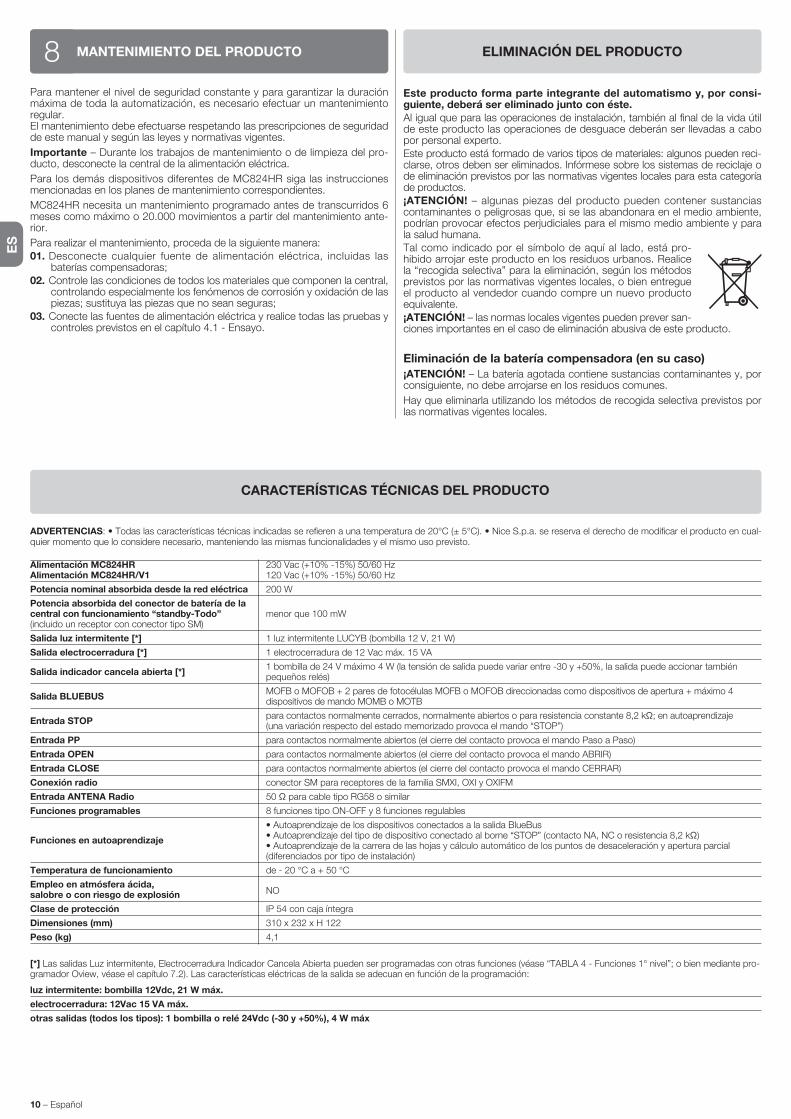
ES
10 – Español
ADVERTENCIAS: • Todas las características técnicas indicadas se refieren a una temperatura de 20°C (± 5°C). • Nice S.p.a. se reserva el derecho de modificar el producto en cual-quier momento que lo considere necesario, manteniendo las mismas funcionalidades y el mismo uso previsto.
Alimentación MC824HR 230 Vac (+10% -15%) 50/60 Hz Alimentación MC824HR/V1 120 Vac (+10% -15%) 50/60 Hz
Potencia nominal absorbida desde la red eléctrica 200 W
Potencia absorbida del conector de batería de la central con funcionamiento “standby-Todo” menor que 100 mW (incluido un receptor con conector tipo SM)
Salida luz intermitente [*] 1 luz intermitente LUCYB (bombilla 12 V, 21 W)
Salida electrocerradura [*] 1 electrocerradura de 12 Vac máx. 15 VA
Salida indicador cancela abierta [*] 1 bombilla de 24 V máximo 4 W (la tensión de salida puede variar entre -30 y +50%, la salida puede accionar también
pequeños relés)
Salida BLUEBUS MOFB o MOFOB + 2 pares de fotocélulas MOFB o MOFOB direccionadas como dispositivos de apertura + máximo 4
dispositivos de mando MOMB o MOTB
Entrada STOP para contactos normalmente cerrados, normalmente abiertos o para resistencia constante 8,2 kΩ; en autoaprendizaje
(una variación respecto del estado memorizado provoca el mando “STOP”)
Entrada PP para contactos normalmente abiertos (el cierre del contacto provoca el mando Paso a Paso)
Entrada OPEN para contactos normalmente abiertos (el cierre del contacto provoca el mando ABRIR)
Entrada CLOSE para contactos normalmente abiertos (el cierre del contacto provoca el mando CERRAR)
Conexión radio conector SM para receptores de la familia SMXI, OXI y OXIFM
Entrada ANTENA Radio 50 Ω para cable tipo RG58 o similar
Funciones programables 8 funciones tipo ON-OFF y 8 funciones regulables
• Autoaprendizaje de los dispositivos conectados a la salida BlueBus
Funciones en autoaprendizaje • Autoaprendizaje del tipo de dispositivo conectado al borne “STOP” (contacto NA, NC o resistencia 8,2 kΩ)
• Autoaprendizaje de la carrera de las hojas y cálculo automático de los puntos de desaceleración y apertura parcial (diferenciados por tipo de instalación)
Temperatura de funcionamiento de - 20 °C a + 50 °C
Empleo en atmósfera ácida, NO
salobre o con riesgo de explosión
Clase de protección IP 54 con caja íntegra
Dimensiones (mm) 310 x 232 x H 122
Peso (kg) 4,1
[*] Las salidas Luz intermitente, Electrocerradura Indicador Cancela Abierta pueden ser programadas con otras funciones (véase “TABLA 4 - Funciones 1° nivel”; o bien mediante pro-gramador Oview, véase el capítulo 7.2). Las características eléctricas de la salida se adecuan en función de la programación:
luz intermitente: bombilla 12Vdc, 21 W máx.
electrocerradura: 12Vac 15 VA máx.
otras salidas (todos los tipos): 1 bombilla o relé 24Vdc (-30 y +50%), 4 W máx
CARACTERÍSTICAS TÉCNICAS DEL PRODUCTO
MANTENIMIENTO DEL PRODUCTO8Para mantener el nivel de seguridad constante y para garantizar la duración máxima de toda la automatización, es necesario efectuar un mantenimiento regular.El mantenimiento debe efectuarse respetando las prescripciones de seguridad de este manual y según las leyes y normativas vigentes.
Importante – Durante los trabajos de mantenimiento o de limpieza del pro-ducto, desconecte la central de la alimentación eléctrica.
Para los demás dispositivos diferentes de MC824HR siga las instrucciones mencionadas en los planes de mantenimiento correspondientes.
MC824HR necesita un mantenimiento programado antes de transcurridos 6 me ses como máximo o 20.000 movimientos a partir del mantenimiento ante-rior.
Para realizar el mantenimiento, proceda de la siguiente manera:01. Desconecte cualquier fuente de alimentación eléctrica, incluidas las
baterías compensadoras;02. Controle las condiciones de todos los materiales que componen la central,
controlando especialmente los fenómenos de corrosión y oxidación de las piezas; sustituya las piezas que no sean seguras;
03. Conecte las fuentes de alimentación eléctrica y realice todas las pruebas y controles previstos en el capítulo 4.1 - Ensayo.
ELIMINACIÓN DEL PRODUCTO
Este producto forma parte integrante del automatismo y, por consi-guiente, deberá ser eliminado junto con éste.Al igual que para las operaciones de instalación, también al final de la vida útil de este producto las operaciones de desguace deberán ser llevadas a cabo por personal experto.Este producto está formado de varios tipos de materiales: algunos pueden reci-clarse, otros deben ser eliminados. Infórmese sobre los sistemas de reciclaje o de eliminación previstos por las normativas vigentes locales para esta categoría de productos.¡ATENCIÓN! – algunas piezas del producto pueden contener sustancias contaminantes o peligrosas que, si se las abandonara en el medio ambiente, podrían provocar efectos perjudiciales para el mismo medio ambiente y para la salud humana.Tal como indicado por el símbolo de aquí al lado, está pro-hibido arrojar este producto en los residuos urbanos. Realice la “recogida selectiva” para la eliminación, según los métodos previstos por las normativas vigentes locales, o bien entregue el producto al vendedor cuando compre un nuevo producto equivalente.¡ATENCIÓN! – las normas locales vigentes pueden prever san-ciones importantes en el caso de eliminación abusiva de este producto.
Eliminación de la batería compensadora (en su caso)
¡ATENCIÓN! – La batería agotada contiene sustancias contaminantes y, por consiguiente, no debe arrojarse en los residuos comunes.
Hay que eliminarla utilizando los métodos de recogida selectiva previstos por las normativas vigentes locales.

DE
Deutsch – 1
DEUTSCH
InhaltsverzeichnisALLGEMEINE SICHERHEITSHINWEISE UND MASSNAHMEN . . . . . . . 1Sicherheitshinweise . . . . . . . . . . . . . . . . . . . . . . . . . . . . . . . . . . . . . . . . . . . 1Hinweise zur Installation . . . . . . . . . . . . . . . . . . . . . . . . . . . . . . . . . . . . . . . . 1Hinweise zur Bedienungo . . . . . . . . . . . . . . . . . . . . . . . . . . . . . . . . . . . . . . . 1
1 - PRODUKTBESCHREIBUNG UND EINSATZ . . . . . . . . . . . . . . . . . . . . 1
2 - INSTALLATION . . . . . . . . . . . . . . . . . . . . . . . . . . . . . . . . . . . . . . . . . . . 12.1 - Überprüfungen vor der Installation . . . . . . . . . . . . . . . . . . . . . . . . . . . . 12.2 - Einsatzgrenzen des Produktes . . . . . . . . . . . . . . . . . . . . . . . . . . . . . . . 22.3 - Typische Anlage . . . . . . . . . . . . . . . . . . . . . . . . . . . . . . . . . . . . . . . . . . 22.4 - Installierung der Steuerung . . . . . . . . . . . . . . . . . . . . . . . . . . . . . . . . . 2
3 - ELEKTRISCHE ANSCHLÜSSE . . . . . . . . . . . . . . . . . . . . . . . . . . . . . . 23.1 - Beschreibung der elektrischen Anschlüsse . . . . . . . . . . . . . . . . . . . . . . 23.2 - Stromanschlüsse der Steuerung MC824HR . . . . . . . . . . . . . . . . . . . . . 33.3 - Verbindung sonstiger Vorrichtungen an MC824HR . . . . . . . . . . . . . . . . 33.4 - Adressierung der mit MC824HR angeschlossenen Vorrichtungen . . . . 33.5 - Ersteinschaltung und Prüfung der Anschlüsse . . . . . . . . . . . . . . . . . . . 33.6 - Erlernung der mit MC824HR verbundenen Vorrichtungen . . . . . . . . . . 33.7 - Erlernung der Positionen der mechanischen Endanschläge . . . . . . . . . 3 3.7.1 - Automatische Erlernung . . . . . . . . . . . . . . . . . . . . . . . . . . . . . . 4 3.7.2 - Manuelles Erlernungsverfahren . . . . . . . . . . . . . . . . . . . . . . . . . 4 3.7.3 - Gemischtes Erlernungsverfahren . . . . . . . . . . . . . . . . . . . . . . . . 43.8 - Überprüfung der Bewegung der Torflügel . . . . . . . . . . . . . . . . . . . . . . . 4
4 - ABNAHME UND INBETRIEBSETZUNG . . . . . . . . . . . . . . . . . . . . . . . 44.1 - Abnahme . . . . . . . . . . . . . . . . . . . . . . . . . . . . . . . . . . . . . . . . . . . . . . . 54.2 - Inbetriebsetzung . . . . . . . . . . . . . . . . . . . . . . . . . . . . . . . . . . . . . . . . . . 5
5 - PROGRAMMIERUNG . . . . . . . . . . . . . . . . . . . . . . . . . . . . . . . . . . . . . . 55.1 - Programmierung erstes Niveau (ON-OFF) . . . . . . . . . . . . . . . . . . . . . . . 55.2 - Zweites Niveau: Programmierung (einstellbare Parameter) . . . . . . . . . . 65.3 - Spezielle Funktionen . . . . . . . . . . . . . . . . . . . . . . . . . . . . . . . . . . . . . . . 75.4 - Löschen des Speichers . . . . . . . . . . . . . . . . . . . . . . . . . . . . . . . . . . . . 8
6 - WAS TUN, WENN ... (Leitfaden zum Lösen von Problemen) . . . . . . 8
7 - WEITERE AUSKÜNFTE . . . . . . . . . . . . . . . . . . . . . . . . . . . . . . . . . . . . 97.1 - Anschluss eines Funkempfängers . . . . . . . . . . . . . . . . . . . . . . . . . . . . 97.2 - Anschluss des Oview-Programmiergeräts . . . . . . . . . . . . . . . . . . . . . . 97.3 - Anschluss des Systems an die Solarenergie Solemyo . . . . . . . . . . . . . 97.4 - Anschluss der Pufferbatterie Mod. PS324 . . . . . . . . . . . . . . . . . . . . . . 9
8 - WARTUNG DES PRODUKTES . . . . . . . . . . . . . . . . . . . . . . . . . . . . . 10
ENTSORGUNG DES PRODUKTES . . . . . . . . . . . . . . . . . . . . . . . . . . . . . 10
TECHNISCHE MERKMALE DES PRODUKTS . . . . . . . . . . . . . . . . . . . . 10
CE-KONFORMITÄTSERKLÄRUNG . . . . . . . . . . . . . . . . . . . . . . . . . . . . . III
Anweisungen und Hinweise für den Benutzer . . . . . . . . . . . . . . . . . . . . IXDARSTELLUNGEN . . . . . . . . . . . . . . . . . . . . . . . . . . . . . . . . . . . . . . . . . . XII
MC824HR ist eine elektronische Zentrale für die Automatisierung von Schwing-toren mit Motoren der Serie Toona Modell 5624I (siehe Kapitel „2.2 Nutzungs-grenzen des Produktes“). ACHTUNG! – Jeder andere Einsatz, auch unter anderen Be dingungen, als in dieser Gebrauchsanleitung aufgeführt, ist als falsch zu betrachten und somit verboten!
Die Steuerung ist speziell dafür vorgerüstet, um an die Vorrichtungen des Systems Opera, Bluebus und des Solarspeisungssystem Solemyo angeschlossen zu werden.Wenn sie durch Netzstrom gespeist wird, kann eine Pufferbatterie eingebaut werden (Mod. PS324, Optional), die der Automatisierung im Falle eines Strom-ausfalls in den nächsten Stunden einige Bewegungen ermöglicht.Weitere verfügbare Zubehörteile sind die vorgerüsteten Empfänger mit “SM”-Kupplung (SMXI, OXI, usw.).
PRODUKTBESCHREIBUNG UND EINSATZ1
Sicherheitshinweise
• ACHTUNG! – Diese Gebrauchsanleitung enthält wichtige Anleitungen und Hinweise für die Sicherheit der Personen. Die Personen können durch eine falsche Installation schwer verletzt werden. Daher ist es wichtig, alle Ab schnitte des Handbuchs vor Installationsbeginn zu lesen. Im Zweifelsfall die Installation unterbrechen und den Nice Kundendienst um Erklärungen bitten.
• ACHTUNG! – Wichtige Anweisungen: Bewahren Sie das vorliegende Handbuch auf, um zukünftige Entsorgungs- oder Wartungsarbeiten am Produkt zu erleichtern.
• ACHTUNG! – Nach der neusten Europäischen Gesetzgebung muss die Ausführung einer Automatiktür oder eines ebensolchen Tors den Normen der Richtlinie 2006/42/CE (vorher 98/37/EG) (Maschinen-richtlinie) und im Besonderen den Normen EN 12445; EN 12453; EN 12635 und EN 13241-1entsprechen, durch sie wird die vorausgesetz-te Konformität der Automation erklärt. In Anbetracht dessen, müssen alle Installations- und Anschlussarbeiten, die Endabnahme und War-tung des Produkts ausschließlich von zuständigen und qualifizierten Technikern durchgeführt werden!
Hinweise zur Installation
• Vor der Installation prüfen, ob dieses Produkt für die gewünschte Anwen-dung geeignet ist (siehe Abschnitt 2.2 “Anwendungslimits” und Kapitel “Technische Produkteigenschaften2). Wenn es nicht geeignet ist, NICHT zur Installation fortschreiten.
• Der Inhalt dieses Handbuchs bezieht sich auf eine typische Anlage, wie in Abb. 2a beschrieben wird.
• Bei allen Installations- und Wartungsarbeiten muss die Automati-on vom Stromnetz abgetrennt sein. Wenn die Abtrennvorrichtung vom Unterbringungsort der Automatisierung nicht zu sehen ist, muss vor Beginn der Arbeiten auf der Abtrennvorrichtung ein Schild mit der Schrift “ACH-TUNG! LAUFENDE WARTUNG” angebracht werden.
• Im Speisungsnetz der Anlage eine Trennvorrichtung mit einem Kontaktöff-nungsabstand vorsehen, der die vollständige Trennung laut den Vorschriften der Überspannungskategorie III ermöglicht.
• Die Steuerung muss an einer elektrischen Versorgungsleitung mit Sicher-heitserdung angeschlossen sein.
• Das Produkt bei der Installation vorsichtig behandeln; keinen Quetschungen, Stößen, Stürzen oder Kontakt mit beliebigen Flüssigkeiten aussetzen. Das Produkt keinen Wärmequellen oder offenen Flammen aussetzen. Solche Handlungen können ihn schädigen und Betriebsstörungen oder Gefahren verursachen. Sollte dies der Fall sein, die Installation unverzüglich unterbre-chen und den Nice Kundendienst kontaktieren.
• Keine Änderungen am Produkt vornehmen. Unerlaubte Vorgänge können mangelhafte Funktionen hervorrufen. Der Hersteller übernimmt keinerlei Haf-tung für Schäden, die durch willkürlich veränderte Produkte entstanden sind.
• Das Verpackungsmaterial des Produktes muss unter voller Einhaltung der örtlichen Vorschriften entsorgt werden.
Hinweise zur Bedienung
• Das Produkt darf nicht von Personen (einschließlich Kindern) verwendet wer-den, deren physische, empfindungsbezogenen oder geistigen Fähigkeiten eingeschränkt sind, oder die keine Erfahrung oder Kenntnisse besitzen, außer wenn diese mittels einer für ihre Sicherheit verantwortlichen Person überwacht werden oder Anleitungen über die Anwendung des Produkts erhalten haben.
• Kinder, die sich in der Nähe des Produkts aufhalten, müssen überwacht wer-den, damit sie nicht mit diesem spielen.
• Kinder dürfen nicht mit den befestigten Bedienvorrichtungen spielen. Die trag-baren Bedienvorrichtungen (Fernbedienungen) gehören nicht in Kinderhände.
ALLGEMEINE SICHERHEITSHINWEISE UND MASSNAHMEN
2.1 - Überprüfungen vor der Installation
Vor Arbeitsbeginn die Eignung des gewählten Modells und der für die Installati-on bestimmten Umgebung prüfen:• Prüfen, ob das gesamte benutzte Material in bestem Zustand und für den
Einsatz geeignet ist.
INSTALLATION2

ELEKTRISCHE ANSCHLÜSSE3Der Stromanschluss der verschiedenen Vorrichtungen (Lichtschranken, Digi-taltastaturen, Transponder-Kartenlesegeräte usw.) in der Automatisierung mit Ste uerung muss über das Nice-Bluebus-System ausgeführt werden.
3.1 - Beschreibung der elektrischen Anschlüsse (Abb. 6)
ANTENNE Eingang für die Antenne eines Funkempfängers
FLASH Ausgang für 1 Blinkleuchte mit 12V-Lampe (höchstens 21 W). [*]
ELS Ausgang für Elektroschloss 12 Vac (höchstens 15 VA). [*]
S.C.A. “Kontrolllampe Tor Auf”: Ausgang für 1 Blinkleuchte mit 24V-Lam-pe (höchstens 4 W). [*]
BLUEBUS Eingang für kompatible Vorrichtungen (MOFB, MOFOB, MOB und MOTB; Anschluss der Vorrichtungen parallel auf 2 Leitern, auf denen die Stromversorgung wie die Kommunikationssigna-le verlaufen; keine einzuhaltende Polarität. Der zu verwendende Stromanschluss erfolgt parallel, wobei keine Polaritäten eingehalten werden müssen. Während der Erlernungsphase wird jede an der Steuerung angeschlossene Vorrichtung dank eines unverwechsel-baren Codes einzeln von dieser erkannt. Wenn eine Vorrichtung zugefügt oder beseitigt wird, muss die Erlernung dieser durch die Steuerung ausgeführt werden (siehe Ab schnitt 3.6).
STOP Eingang für Vorrichtungen, die mit ihrem Eingriff den sofortigen Stopp der vorliegenden Bewegung hervorrufen, der eine kurze Umkehrung folgt; die Möglichkeit, NA-, NC- Kontakte anzuschlie-ßen oder Vorrichtungen mit einem Ausgang mit einem konstanten Widerstand 8,2 kΩ (Schaltleisten). Jede an diesem Eingang ange-schlossene Vorrichtung wird während der Erlernung durch die Steuerung einzeln erkannt (Abschnitt 3.6); in dieser Phase wird ein STOPP hervorgerufen, wenn die Steuerung eine Änderung gegen-
über dem erlernten Zustand erfasst. Es ist möglich, an diesen Eingang eine oder mehrere, auch unterschiedliche Vorrichtungen anzuschließen:
– Mehrere NA-Vorrichtungen können miteinander in unbegrenzter Menge parallel angeschlossen werden;
– mehrere NC-Vorrichtungen ohne Mengenbegrenzung serienmä-ßig anschließen);
– 2 Vorrichtungen mit Ausgang mit konstantem Widerstand 8,2 kΩ parallel anschließen. Wenn mehr als 2 Vorrichtungen vor-liegen, müssen sie mit nur einem 1 Endwiderstand mit 8,2 kΩ kaskadengeschaltet werden;
– 2 NA- und NC-Vorrichtungen parallel anschließen, an den NC-Kontakt einen Widerstand mit 8,2kΩ serienmäßig anschließen (das ermöglicht auch die Kombination zwischen den 3 NA - NC-Vorrichtungen und 8,2 kΩ)
P.P. Eingang für Steuervorrichtungen, die nach ihrem Eingriff die Bewe-gung im Schrittbetrieb hervorrufen; es besteht die Möglichkeit, NA-Kontakte anzuschließen
OPEN Eingang für Steuervorrichtungen, die nach ihrem Eingriff nur die Öff-nungsbewegung hervorrufen; es besteht die Möglichkeit, NA-Kon-takte anzuschließen
CLOSE Eingang für Steuervorrichtungen, die nach ihrem Eingriff nur die Schließbewegung hervorrufen; es besteht die Möglichkeit, NA-Kon-takte anzuschließen
ENC1 Eingang Encoder - Torantrieb 1 (Klemme 1, 2), keine einzuhaltende Polarität
ENC2 Eingang Encoder - Torantrieb 2 (Klemme 4, 5), keine einzuhalten-de Polarität
M1 Ausgang für Torantrieb 1 (Klemme 7, 8, 9)
M2 Ausgang für Torantrieb 2 (Klemme 10, 11, 12)[*] Die Ausgänge FLASH, ELS und S.C.A. können mit anderen Funktionen pro-grammiert werden (siehe “TABELLE 4 - Funktionen 1. Niveau; oder durch den Oview-Programmierer, siehe Kapitel 7.2).
• Prüfen, ob alle Anwendungsbedingungen innerhalb der “Anwendungslimits” liegen (Abschnitt 2.2) und den “Technischen Eigenschaften” des Produkts entsprechen.
• Prüfen, ob die zur Installation gewählte Umgebung mit dem Gesamtplatzbe-darf des Produkts kompatibel ist (Abb. 1).
• Prüfen, ob die für die Installation gewählte Oberfläche solide ist und daher eine stabile Befestigung garantieren kann.
• Prüfen, ob sich der Bereich, in dem das Produkt befestigt wird, nicht über-schwemmt werden kann; das Produkt ggf. über dem Boden installieren.
• Prüfen, ob der Platz um das Produkt einen leichten und sicheren Zugang ermöglicht.
• Prüfen, ob alle zu verwendenden Stromkabel den Angaben der Tabelle 1 entsprechen.
• Prüfen, ob in der Automatisierung mechanische Stopps während des Schlie-ßens und Öffnens vorliegen.
2.2 - Einsatzgrenzen des Produktes
Die Zentrale MC824HR darf nur mit den Getriebemotoren Toona Mod. 5624I benutzt werden; diese Motoren sind umkehrbar: d.h. man kann die Torflügel manuell bewegen, ohne den Getriebemotor manuell entriegeln zu müssen. Dank einem Sensor, der im Motor integriert ist, ist die Zentrale in der Lage, die manuelle Bewegung zu erfassen und daraufhin die darauf folgenden Manöver korrekt auszuführen; dies dient dazu zu vermeiden, dass die Torflügel gegen die mechanischen Öffnung- und Schließ-Endanschläge stoßen. Achtung! - Wenn die Zentrale nicht korrekt mit Strom versorgt wird oder die Funktion „Stand By Alles“ aktiv ist, wird die manuelle Bewegung der Torflügel nicht erfasst.
2.3 - Typische Anlage
Die Abb. 2a zeigt als Beispiel eine mit Teilen von Nice ausgeführte Automati-onsanlage:a - Steuerungb - Torantrieb
c - Blinkleuchted - Lichtschrankee - Digitaltastatur - Transponder-Lesegerät - Schlüsselwahlschalterf - Standsäule für Lichtschrankeg - Mechanische Anschläge in Öffnungh - Mit mechanischem Endanschlag in der Schließungi - Elektroschloss
Diese Bestandteile sind gemäß einem typischen und gewöhnlichen Schema plat-ziert. In Bezug auf die Abb. 2a wird die ungefähre Position festgesetzt, in der jedes in der Anlage vorgesehene Teil installiert wird. Wichtig – Vor der Installation die für Ihre Anlage notwendigen Stormkabel vorbereiten, wobei Sie sich auf die Abb. 2b und die “Tabelle 1 - Technische Eigenschaften der Stromkabel” beziehen.Achtung – Während der Verlegung der Rohre für die Stromkabel und den Ein-tritt der Kabel in den Behälter der Steuerung, muss beachtet werden, dass die Verbindungsrohre aufgrund möglicher Wasserablagerungen in den Abzweig-schächten Kondenswasser innerhalb der Steuerung bilden können, die die elektronischen Kreise beschädigen könnten.
2.4 - Installation der Steuerung
Zur Befestigung der Steuerung wie in fig. 3 gezeigt vorgehen:01. Das Gehäuse der Steuerung durch Abschrauben der jeweiligen Schrau-
ben öffnen (Abb. 3-A);02. Die Bohrungen zum Durchführen der Elektrokabel vorbereiten (Abb. 3-B);03. Das Gehäuse befestigen (Abb. 3-C);04. Nun können die Stromanschlüsse vorgenommen werden: Siehe Kap. 3.Achtung! – Um den Eingang der Rohre für die Stromkabel vorzubereiten, muss die untere Seite des Gehäuses der Steuerung gebohrt werden. Anmer-kung – Wenn notwendig, kann der seitliche Kabeleingang verwendet werden, aber nur bei Anwendung geeigneter Rohranschlüsse.Um die Installierung der anderen in der Automatisierung vorliegenden Vorrich-tungen auszuführen, bezieht man sich auf die jeweiligen Gebrauchsanleitungen.
Anschluss Kabelart Zulässige Höchstlänge
A: STROMKABEL STEUERUNG 1 Kabel 3 x 1,5 mm2 30 m (Anmerkung 1)
B: KABEL für BLINKLEUCHTE mit Antenne 1 Kabel 2 x 0,5 mm2 20 m 1 Abschirmkabel Typ RG58 20 m (weniger als 5 m wird empfohlen)
C: Kabel BLUEBUS-VORRICHTUNGEN 1 Kabel 2 x 0,5 mm2 20 m (Anmerkung 2)
D: Kabel SCHLÜSSELWAHLSCHALTER 2 Kabel 2 x 0,5 mm2 (Anmerkung 3) 50 m
E: Kabel ZUR SPEISUNG DES TORANTRIEBS 1 Kabel 3 x 1,5 mm2 (Anmerkung 4) 10 m
F: Kabel FÜR DEN ENCODER-ANSCHLUSS 1 Kabel 2 x 1 mm2 (Anmerkung 4) 10 m
G: Kabel ANSCHLUSS ELEKTROSCHLOSS 1 Kabel 2 x 1 mm2 10 m
Anmerkung 1 – Wenn das Versorgungskabel länger als 30 ist, muss ein Kabel mit größerem Querschnitt benutzt (3 x 2,5 mm2) und eine Sicherheitserdung in der Nähe der Automatisierung installiert werden.Anmerkung 2 – Wenn das Bluebus-Kabel 20 m Länge überschreitet, bis höchstens 40 m, muss ein Kabel mit einem höheren Schnitt verwendet werden (2x1 mm2)Anmerkung 3 – Diese beiden Kabel 2 können mit nur einem Kabel 4 x 0,5 mm2 ersetzt werden.Anmerkung 4 – Diese beiden Kabel können mit nur einem Kabel 5 x 1,5 mm2 ersetzt werden.
ACHTUNG! – Die verwendeten Kabel müssen der Installationsumgebung angepasst werden.
TABELLE 1 – Technische Eigenschaften der Stromkabel (Abb. 2b)

3.5 - Ersteinschaltung und Prüfung der Anschlüsse
Nachdem die Steuerung mit Strom gespeist wurde, die folgenden Prüfungen vornehmen:• Nach einigen Sekunden prüfen, ob die Led “Bluebus” (Abb. 7) regelmäßig mit
1 Blinken pro Sekunde blinkt;• prüfen, ob die Leds der Lichtschranken (Abb. 7) – TX und RX – blinken. Die in
dieser Phase abgegebene Blinkart ist unbedeutend;• Prüfen, ob die am Ausgang FLASH angeschlossene Blinkleuchte ausgeschal-
tet ist.
Wenn all dies nicht erfolgt, muss der Steuerung die Stromspeisung genommen und die verschiedenen zuvor ausgeführten Stromanschlüsse kontrolliert werden.
3.6 - Erlernung der mit MC824HR verbundenen Vorrichtungen
Nachdem die Ersteinschaltung ausgeführt wurde, müssen der Steuerung die an den Eingängen “Bluebus” und “Stop” angeschlossenen Vorrichtungen zur Erkennung gegeben werden.
ACHTUNG! – Die Erlernungsphase muss auch ausgeführt werden, wenn mit der Steuerung keine Vorrichtung verbunden ist.Die Steuerung ist in der Lage, die einzelnen angeschlossenen Vorrichtungen dank der Erlernung zu erkennen und die möglichen vorliegenden Störungen zu erfassen. Hierzu ist es notwendig, die Erlernung der Vorrichtungen jedes Mal dann auszuführen, wenn eine dieser zugefügt oder entfernt wird.Die Led “L1” und “L2” in der Steuerung (Abb. 7), blinken langsam, um anzuzei-gen, dass es notwendig ist, die Erfassung auszuführen:01. Die Tasten “ ” und “Set” (Abb. 7).02. Die Tasten loslassen, wenn die Leds “L1” und “L2” sehr schnell zu blinken
beginnen (nach ca. 3 Sekunden).03. Einige Sekunden abwarten, bis die Steuerung die Erlernungsphase der
Vorrichtungen abgeschlossen hat.04. Am Ende dieser Phase muss die Led “Stop” eingeschaltet und die Leds “L1”
und “L2” müssen ausgeschaltet sein (die Leds “L3” und “L4” könnten zu blinken beginnen).
3.7 - Erlernung der Positionen der mechanischen Endanschläge
Nach der Erlernung der angeschlossenen Vorrichtungen (Abschnitt 3.6) ist es notwendig, die Erlernung der Positionen der mechanischen Anschläge vorzu-nehmen (Höchstöffnung und -schließung). Dieses Verfahren kann auf 3 Arten vorgenommen werden: Automatisch, manuell und gemischt.Im Automatikmodus führt die Steuerung die Erfassung der mechanischen Anschläge aus und kalkuliert die besten Versetzungen der Flügel (SA und SC, Abb. B).Im manuellen Modus werden die acht Positionen der mechanischen Stopps (Abb. B) jeweils programmiert, indem die Flügel auf die gewünschten Stellen versetzt werden. Die zu programmierende Position kann durch das Blinken einer der 8 Leds herausgestellt werden (L1...L8), siehe Tabelle 3.Im gemischten Modus ist es möglich, das automatische Verfahren auszufüh-ren und dann mit dem manuellen Verfahren eine oder mehrere Positionen zu ändern, außer der Positionen “0” und “1” (Abb. B) die mit den Positionen der mechanischen Stopps übereinstimmen.
A
TABELLE 2 - ADRESSEN DER LICHTSCHRANKEN
Lichtschranke Überbrückungen
FOTO Lichtschranke außen h = 50 mit Auslösung während Schließung (stoppt und kehrt die Bewegung um)
FOTO II Lichtschranke außen h = 100 mit Auslösung während Schließung (stoppt und kehrt die Bewegung um)
FOTO 1 Lichtschranke innen h = 50 mit Eingriff während Schließung (stoppt und kehrt die Bewegung um), wie auch während der Öffnung (stoppt und geht weiter, wenn die Lichtschranke frei ist)
FOTO 1 II Lichtschranke innen h = 100 mit Eingriff während Schließung (stoppt und kehrt die Bewegung um), wie auch während der Öffnung (stoppt und geht weiter, wenn die Lichtschranke frei ist)
FOTO 2 Lichtschranke innen mit Auslösung während Öffnung (stoppt und kehrt die Bewegung um)
FOTO 2 II Lichtschranke innen mit Auslösung während Öffnung (stoppt und kehrt die Bewegung um)
FOTO 3 UNERLAUBTE KONFIGURATION
3.2 - Stromanschlüsse der Steuerung MC824HR
Nachdem das Gehäuse der Steuerung befestigt wurde und die Bohrungen für den Durchgang der Stromkabel vorgesehen wurden (Kap. 2.4 und Abb. 3), die elektrischen Anschlüsse ausführen:
ACHTUNG!– Alle Stromanschlüsse müssen ohne Netzstromspeisung und bei abgetrennter Pufferbatterie ausgeführt werden, wenn diese in der Automatisierung installiert ist.– Die Anschlussarbeiten dürfen nur von qualifiziertem Personal ausge-führt werden.– An der Netzstromleitung muss eine Vorrichtung vorgesehen werden, die die vollständige Trennung der Automatisierung vom Netz sichert. Die Trennungs-vorrichtung muss Kontakte mit einer Öffnungsdistanz aufweisen, die eine vollständige Trennung unter den von der Überspannungskategorie III vorge-sehenen Bedingungen ermöglicht sowie den Installationsregeln entsprechen. Bei Bedarf garantiert diese Vorrichtung ein schnelles und sicheres Abtrennen der Spannungsversorgung. Sie muss daher in Sichtweite der Automatisierung angebracht sein. Falls sie in nicht sichtbarer Stellung angebracht ist, muss sie – um Gefahren zu vermeiden - über ein System verfügen, das eine unbeabsich-tigte oder nicht autorisierte Einschaltung der Spannungsversorgung blockiert. Die Abtrennvorrichtung wird nicht mit dem Produkt geliefert.
01. Zuerst das Stromkabel (Abb. 4) anschließen und mit dem Kabelniederhal-ter sperren;
02. Nun die Stromkabel der Motoren M1 und M2 anschließen, wobei die Sym-bole auf der Etikette eingehalten werden (Abb. 5):
a) An die Klemme M1 den Motor anschließen, der den unteren Flügel antreibt (der zweite, der die Öffnungsbewegung beginnt) und dann den jeweiligen Encoder an die Klemmen 1-2 anschließen;
b) An die Klemme M2 den Motor anschließen, der den oberen Flügel an treibt (der erste, der die Öffnungsbewegung beginnt) und dann den jeweiligen Encoder an die Klemmen 4-5 anschließen;
WICHTIG! - Wenn in der Anlage nur ein Torantrieb vorliegt, muss er an die Klemme M2 angeschlossen und die Klemme M1 freigelassen werden;
03. Nun die Stromkabel der verschiedenen vorhandenen Stromkabel anschlie-ßen, wobei man sich auf Abb. 6 bezieht (siehe Abschn. 3.3). Anmerkung – Zur Erleichterung der Kabelanschlüsse können die Klemmen aus ihren Einsätzen gezogen werden.
3.3 - Verbindung sonstiger Vorrichtungen an MC824HR
Wenn weitere in der Anlage vorliegende Vorrichtungen, wie zum Beispiel ein Transponder-Kartenlesegerät oder die Beleuchtung für den Schlüsselwahl-schalter gespeist werden müssen, können diese Vorrichtungen an die Steue-rung über die Klemmen P.P. (Plus) und STOP (Minus) angeschlossen werden (Abb. 6). Die Stromspannung beträgt 24 Vcc (-30% ÷ +50%) mit einem maxi-mal erhältlichen Strom von 200 mA.Anmerkung – Die verfügbare Spannung in den Klemmen “P.P.” und “STOP” verbleibt auch, wenn die Funktion “Stand By” in der Karte aktiviert wird.
3.4 - Adressierung der mit MC824HR angeschlossenen Vorrich-tungen
Um der Steuerung zu ermöglichen, die am System Bluebus angeschlossenen Vorrichtungen zu erkennen, muss die Adressierung dieser ausgeführt werden. Dieser Vorgang muss durch die korrekte Positionierung der in jeder Vorrichtung vorliegenden Brücke vorgenommen werden, siehe Gebrauchsanleitung jeder einzelnen Vorrichtung. Siehe Abb. A und Tabelle 2.Am Ende der Installation oder nach der Entfernung der Lichtschranken oder anderer Vorrichtungen ist es notwendig, das Erlernungsverfahren dieser vorzu-nehmen, siehe Abschnitt 3.6.
0
1 1A
SC
SA
A
0M1 M2
B POSITIONEN
TABELLE 3
Position Led Beschreibung
Position 0(Motor 1)
Position 0(Motor 2)
Position SA(Motor 2)
Position A(Motor 1)
Position der maximalen Schließung: Wenn der Flügel 1 auf den mechanischen Schließanschlag stößt
Position der maximalen Schließung: Wenn der Flügel 2 auf den mechanischen Schließanschlag stößt
Verschiebung bei Öffnung: wenn der Flügel 2 diese Position überschreitet, beginnt die Öffnung des Flügels 1
Gewünschte Öffnungsposition Position, in der der mit dem Mo tor 1 verbundene Flügel am Ende einer Öffnungsbewegung anhal-ten muss. Es ist nicht notwendig, dass diese Position mit der mechanischen Öffnungsbefestigung übereinstimmt, sie kann nach Wahl zwischen “0” und “1” gewählt werden.
L1
L2
L3
L4

DE
4 – Deutsch
3.7.1 - Erlernung im Automatikmodus01. Die Tasten “ ” und “Set” drücken und gleichzeitig gedrückt halten;02. Die Tasten loslassen, wenn die Leds “L3” und “L4” sehr schnell zu blinken
beginnen (nach ca. 3 Sekunden).03. Prüfen, ob die Automatisierung die folgenden Bewegungsfolgen ausführt: a - Langsames Schließen des Torantriebs M1 bis zum mechanischen End-
anschlag b - Langsames Schließen des Torantriebs M2 bis zum mechanischen
Endanschlag c - Langsames Öffnen des Torantriebs M2 und des Torantriebs M1 bis
zum mechanischen Endanschlag d - Schnelles vollständiges Schließen des Torantriebs M1 und M2
HINWEISE:– Wenn die erste Bewegung (a) den durch Motor M1 gesteuerten Flügel
nicht schließt, sondern den durch M2 gesteuert, muss die Taste “ ” oder “ ” gedrückt werden, um die Erlernungsphase zu stoppen. Nun werden die Anschlüsse der Motoren M1 und M2 an den Klemmen der Steuerung umgekehrt und dann die der jeweiligen Encoder; schließlich das Verfahren ab Punkt 01 beginnen;
– Wenn die ersten 2 Bewegungen (a und b) nicht als “Schließungen”, son-dern als “Öffnungen” erfolgen, die Taste “ “ oder “ “ drücken, um die Erler-nungsphase zu stoppen. Dann am Torantrieb, der die Öffnungsbewegung ausgeführt hat, die Polaritäten der beiden Kabel des Torantriebs M1 umkeh-ren (Klemmen 7 und 9), ebenso bei M2 (Klemmen 10 und 12), dann das Verfahren ab Punkt 01 beginnen.
04. Am Ende der Schließbewegung der 2 Motoren (d), schalten die Leds “L3“ und “L4“ ab und zeigen somit an, dass das Verfahren korrekt ausgeführt wurde.
Hinweise:– Wenn während der automatischen Erlernungsphase der Eingriff der Licht-
schranken oder einer am Eingang „Stopp“ angeschlossenen Vorrichtung erfolgt, wird das Verfahren unterbrochen und die Led L1 beginnt zu blinken. Um die Erlernung wieder zu aktivieren, muss das Verfahren ab Punkt 01 wie-der aufgenommen werden.
– Das automatische Erlernungsverfahren kann erneut in jedem Moment vorge-nommen werden, auch der Ausführung der Installation; zum Beispiel infolge der Änderung der Position der mechanischen Stopps.
3.7.2 - Manuelles ErlernungsverfahrenACHTUNG! - Ab Schritt 03 gilt:– Um von Led L1 auf L8 zu gehen, muss ein kurzes Drücken der Taste oder
erfolgen (die Led blinkt und zeigt die aktuelle Position an);
– Um den Motor in eine oder die andere Richtung zu bewegen, muss ein stän-diger Druck der Taste oder erfolgen.
01. Die Tasten “ ” und “Set” drücken und gleichzeitig gedrückt halten;02. Die Tasten freigeben, wenn die “L1” zu blinken beginnt (nach zirka 1
Sekunde); Anmerkung – Nach 3 Sekunden und wenn die Tasten “Set” und “ ” nicht freigegeben werden, wird das Verfahren der “automatischen Erlernung” und nicht das manuelle aktiviert.
03. • die Led L1 blinkt: Position 0 des M1 Um den Motor 1 zu steuern und in die Position 0 (Abb. B) zu bringen:
Die Taste “ ” oder “ ” drücken und gedrückt halten. Nach Erreichen der Position, die Taste freigeben, um die Bewegung zu stoppen. Um die Position zu speichern, die Taste “Set” mindestens 3 Sek. drücken und gedrückt halten, dann freigeben (nach 2 Sek. bleibt die L1 eingeschaltet und nach Freigabe der Taste “Set” beginnt die Led L2 zu blinken).
• die Led L2 blinkt: Position 0 des M2 Um den Motor 2 zu steuern und in die Position 0 (Abb. B) zu bringen:
Die Taste “ ” oder “ ” drücken und gedrückt halten. Nach Erreichen der Position, die Taste freigeben, um die Bewegung zu stoppen. Um die Position zu speichern, die Taste “Set” mindestens 3 Sek. drücken und gedrückt halten, dann freigeben (nach 2 Sek. bleibt die L2 eingeschaltet und nach Freigabe der Taste “Set” beginnt die Led L3 zu blinken).
• die Led L3 blinkt: Position SA des M2 Um den Motor 2 zu steuern und in die Position SA (Abb. B) zu bringen:
Die Taste “ ” oder “ ” drücken und gedrückt halten. Nach Erreichen der Position, die Taste freigeben, um die Bewegung zu stoppen. Um die Position zu speichern, die Taste “Set” mindestens 3 Sek. drücken und gedrückt halten, dann freigeben (nach 2 Sek. bleibt die L3 eingeschaltet und nach Freigabe der Taste “Set” beginnt die Led L4 zu blinken).
• die Led L4 blinkt: Position A des M1 Um den Motor 1 zu steuern und in die Position A (Abb. B) zu bringen:
Die Taste “ ” oder “ ” drücken und gedrückt halten. Nach Erreichen der Position, die Taste freigeben, um die Bewegung zu stoppen. Um die Position zu speichern, die Taste “Set” mindestens 3 Sek. drücken und gedrückt halten, dann freigeben (nach 2 Sek. bleibt die L4 eingeschaltet und nach Freigabe der Taste “Set” beginnt die Led L5 zu blinken).
• die Led L5 blinkt: Position A des M2
Um höchste Sicherheit bei der Ausführung der Automatisierung zu gewähr-leisten führen wir die wichtigsten Schritte auf. Die Abnahme kann genützt wer-den, um auch die Bestandteile der Automatisierung regelmäßig zu prüfen. Die Abnahme und Inbetriebnahme der Automatisierung müssen durch qualifiziertes und erfahrenes Personal ausgeführt werden, das die notwendigen Prüfungen festsetzt, um die geeigneten Lösungen hinsichtlich der vorliegenden Risiken zu finden und die Einhaltung der gesetzlichen Vorschriften, Normen und Regelun-gen zu überwachen. Insbesondere aller Anforderungen der Norm EN 12445, die die Prüfmethoden zur Kontrolle der Automatisierungen für Tore festsetzt.Die zusätzlichen Vorrichtungen müssen einer spezifischen Abnahme unterzo-gen werden, was die Funktionstüchtigkeit angeht, aber auch bezüglich ihrer korrekten Wirkung mit MC824HR, somit muss man sich auf die Gebrauchsan-leitung der einzelnen Vorrichtungen beziehen.
ABNAHME UND INBETRIEBSETZUNG4
Um den Motor 2 zu steuern und in die Position A (Abb. B) zu bringen: Die Taste “ ” oder “ ” drücken und gedrückt halten. Nach Erreichen der Position, die Taste freigeben, um die Bewegung zu stoppen. Um die Position zu speichern, die Taste “Set” mindestens 3 Sek. drücken und gedrückt halten, dann freigeben (nach 2 Sek. bleibt die L5 eingeschaltet und nach Freigabe der Taste “Set” beginnt die Led L6 zu blinken).
• die Led L6 blinkt: Position SC des M1 Um den Motor 1 zu steuern und in die Position SC (Abb. B) zu bringen:
Die Taste “ ” oder “ ” drücken und gedrückt halten. Nach Erreichen der Position, die Taste freigeben, um die Bewegung zu stoppen. Um die Position zu speichern, die Taste “Set” mindestens 3 Sek. drücken und gedrückt halten, dann freigeben (nach 2 Sek. bleibt die L6 eingeschaltet und nach Freigabe der Taste “Set” beginnt die Led L7 zu blinken).
• die Led L7 blinkt: Position 1 des M1 Um den Motor 1 zu steuern und in die Position 1 (Abb. B) zu bringen:
Die Taste “ ” oder “ ” drücken und gedrückt halten. Nach Erreichen der Position, die Taste freigeben, um die Bewegung zu stoppen. Um die Position zu speichern, die Taste “Set” mindestens 3 Sek. drücken und gedrückt halten, dann freigeben (nach 2 Sek. bleibt die L7 eingeschaltet und nach Freigabe der Taste “Set” beginnt die Led L8 zu blinken).
• die Led L8 blinkt: Position 1 des M2 Um den Motor 2 zu steuern und in die Position 1 (Abb. B) zu bringen:
Die Taste “ ” order “ ” drücken und gedrückt halten. Nach Erreichen der Position, die Taste freigeben, um die Bewegung zu stoppen. Um die Positi-on zu speichern, die Taste “Set” mindestens 3 Sek. drücken und gedrückt halten, dann freigeben, um aus der Programmierung zu gehen (nach 2 Sek. bleibt die Led L8 bis zur Freigabe der Taste “Set” eingeschaltet).
Hinweis – Manuelle Programmierung einer Anlage mit nur einem Getrie-bemotor: wie zu Beginn dieses Kapitel ab Schritt 01 bis Schritt 03 arbeiten und dann wie folgt fortfahren:- Die Positionen in Bezug auf die LED L1 (0 von M1) und L7 (1 von M1)
wie folgt programmieren: Die Taste „Set“ für mindestens 3 Sek. drücken und dann loslassen (nach 2 Sek. bleibt die LED eingeschaltet und beim Los-lassen der Taste „Set“ beginnt die nächste LED zu blinken).
- Die Positionen der LED L3 (SA von M2) - L4 (A von M1) - L6 (SC von M1) nicht programmieren
- Um sich zwischen den Positionen zu bewegen, drückt man kurz die Taste oder .
3.7.3 - Gemischtes ErlernungsverfahrenDieses Verfahren nach der Ausführung der automatischen Erlernung ausführen:01. Die Tasten “ ” und “Set” drücken und gleichzeitig gedrückt halten;02. Die Tasten freigeben, wenn die “L1” zu blinken beginnt (nach zirka 1
Sekunde); Anmerkung – Nach 3 Sekunden und wenn die Tasten “Set” und “ ” nicht freigegeben werden, wird das Verfahren der “automatischen Erlernung” und nicht das manuelle aktiviert.
03. Durch ein kurzes Drücken der Taste “ ” oder “ ” die blinkende Led (L1…L8) auf die Position verschieben, die programmiert werden soll und für jede einzelne Position vorgehen, wie im Schritt 03 der manuellen Erlernung beschrieben wird (Abschnitt 3.7.2).
Diesen letzten Vorgang bei allen anderen Positionen wiederholen, die geändert werden sollen.
Um die manuelle Erlernung zu beenden, wiederholt die Taste “ ” drücken, bis die blinkende Led nach L8 gebracht wird.
3.8 - Überprüfung der Bewegung der TorflügelAm Ende der Erfassungsphase empfehlen wir, die Steuerung einige Öffnungs- und Schließbewegungen ausführen zu lassen, um die korrekte Bewegung des Tors, die eventuellen Montage- und Einstellmängel zu prüfen.01. Die Taste “Open” drücken. Die korrekte Verschiebung der Flügel während
der Öffnung prüfen und kontrollieren, ob während der Öffnungsbewegung die Beschleunigungsphase, die Phase mit konstanter Geschwindigkeit und die Verzögerungsphase vorliegen. Nach der Bewegung müssen die Flügel einige Zentimeter von dem mechanischen Öffnungsendanschlag anhalten.
02. Die Taste “Close” drücken und prüfen, ob während der Schließbewegung die Beschleunigungsphase, die Phase mit konstanter Geschwindigkeit und die Verlangsamungsphase vorliegen. Die korrekte Verschiebung der Flügel während der Schließung prüfen. Am Ende müssen die Flügel perfekt am mechanischen Schließendanschlag geschlossen sein.
03. Während den Bewegungen prüfen, ob die Blinkleuchte alle 0.5 Sekunden bei eingeschalteter Blinkleuchte blinkt und alle 0.5 Sekunden bei abge-schalteter Blinkleuchte ausführt.
Position A(Motor 2)
Position SC(Motor 1)
Position 1(Motor 1)
Position 1(Motor 2)
Gewünschte Öffnungsposition Position, in der der mit dem Mo tor 2 verbundene Flügel am Ende einer Öffnungsbewegung anhalten muss. Es ist nicht notwendig, dass diese Position mit der mecha-nischen Öffnungsbefestigung übereinstimmt, sie kann nach Wahl zwischen “0” und “1” gewählt werden.
Verschiebung bei Schließung: Wenn der Flügel 1 unter dieser Position ist, beginnt das Schließen des Flügels 2
Position der maximalen Schließung: Wenn der Flügel 1 auf den mechanischen Öffnungsanschlag stößt
Position der maximalen Schließung: Wenn der Flügel 2 auf den mechanischen Öffnungsanschlag stößt
L5
L6
L7
L8

DE
Deutsch – 5
In der Steuerung befinden sich 3 Tasten OPEN ( ), STOP (SET), CLOSE ( ), die verwendet werden können, um die Steuerung während den Prüfungen zu steuern und um die Programmierung der verfügbaren Funktionen auszuführen.Die verfügbaren programmierbaren Funktionen befinden sich auf 2 Niveaus und ihr Betriebszustand wird durch 8 Leds (L1 ... L8) in der Steuerung angezeigt ( eingeschaltete Led = aktive Funktion; abgeschaltete Led = Funktion nicht aktiv).
Die Programmierungstasten verwenden:
OPEN ( ): – Taste zur Steuerung der Toröffnung; – Taste zur Auswahl in der Programmierungsphase.STOP/SET: Taste, um eine Bewegung anzuhalten; falls länger als 5 Sekunden gedrückt, ermöglicht sie den Zugriff auf die Programmierung.CLOSE ( ): – Taste zur Steuerung der Torschließung; – Taste zur Auswahl in der Programmierungsphase.
5.1 - Programmierung erstes Niveau (ON-OFF)
Alle Funktionen der ersten Ebene sind werkseitig auf „OFF“ programmiert. Davon ausgeschlossen ist die Funktion Schließen, die immer auf „ON“ steht. Die Funktionen können jederzeit geändert werden. Um die verschiedenen Funktionen zu prüfen, siehe Tabelle 4. Für das Programmierungsverfahren siehe Tabelle 5.
WICHTIG – Das Programmierungsverfahren weist eine Höchstzeit von 10 Sekunden zwischen dem Druck einer Taste und dem nächsten auf. Nach die-ser Zeitspanne endet das Verfahren automatisch und speichert die bisher aus-geführten Änderungen.
PROGRAMMIERUNG5
TABELLE 4 - Funktionen erstes Niveau
LED Funktion Beschreibung
L1 Automatische Schließung
L2 Schließen nach Durchfahrt der Lichtschranke
L3 Schließt immer (*)
L4 Stand by (Bluebus)
L5 Elektroschloss / zusätzliches Licht
L6 Vorwarnen
L7 “Schließt” wird “teilweise öffnen 1”
L8 Automatisch 1
AKTIVE Funktion: Nach einer Öffnungsbewegung erfolgt eine Pause (gleich der programmierten Pausenzeit), danach startet die Steuerung automatisch eine Schließbewegung. Der werkseitig eingestellte Pausenwert beträgt 30 Sek.
NICHT AKTIVE Funktion: Die Funktion ist “halbautomatisch”.
AKTIVE Funktion: Wenn die Lichtschranken während der Öffnungs- oder Schließbewegung eingreifen, wird die Pausenzeit auf 5 Sek. reduziert, unabhängig von der programmierten “Pausenzeit”.
Bei deaktivierte “automatischer Schließung” und wenn während der Schließung die Lichtschranken eingrei-fen, wird die “automatische Schließung” bei programmierter “Pausenzeit” aktiviert.
AKTIVE Funktion: Im Falle eines auch kurzen Stromausfalls erfasst die Steuerung nach der erneuten Ein-schaltung des Stroms das geöffnete Tor und startet automatisch eine Schließbewegung, die einer 5 Sek. andauernden Vorwarnung folgt.
NICHT AKTIVE Funktion: Nach Rückkehr des Stroms bleibt das Tor, wo es ist.
AKTIVE Funktion: 1 Minute nach Beendigung der Bewegung schaltet die Steuerung den Ausgang BlueBUS (und daher alle Vorrichtungen) sowie alle LEDs mit Ausnahme der BlueBUS-LED aus, die langsamer blinken wird. Wenn die Steuerung einen Befehl erhält, geht sie wieder auf den Normalbetrieb über (mit einer kurzen Verzögerung). Diese Funktion hat das Ziel, den Verbrauch zu reduzieren; ein wichtiger Aspekt mit Batterie- oder Kollektorspeisung.
AKTIVE Funktion: Der Ausgang “Elektroschloss” schaltet seine Funktion auf “zusätzliche Beleuchtung” um.
NICHT AKTIVE Funktion: Der Ausgang funktioniert als Elektroschloss
AKTIVE Funktion: Es kann eine 3 Sekunden lange Pause zwischen dem Einschalten der Blinkleuchte und dem Bewegungsbeginn erfolgen, um die Gefahr vorab bekannt zu geben.
NICHT AKTIVE Funktion: Die Anzeige der Blinkleuchte stimmt mit dem Beginn der Bewegung überein.
AKTIVE Funktion: Der Eingang “Close” der Steuerung schaltet seine Funktion unter “Teilöffnung 1” um.
Funktion AKTIV: bei offenem Tor und „aktivierter automatischer Schließung“, während der Pausezeit, werden die Befehle von den Eingängen und vom Funkempfänger deaktiviert. Die Funktion dieser Bedienungen wird wieder aufgenommen, wenn die Pausezeit abgelaufen ist, sofort nachdem das Schließmanöver begonnen hat.
Funktion NICHT AKTIV: die Bedienungen funktionieren auch während der Pausezeit.
Bezüglich der oben genannten Dokumentation stellt Nice über seinen tech-nischen Kundendienst folgendes zur Verfügung: Gebrauchsanleitungen, Anleitungen und teilweise ausgefüllte Formulare. Siehe auch: www.nice-service.com
(*) Funktion werkseitig aktiv
4.1 - Abnahme
Die für die Abnahme wie folgt beschriebenen Vorgänge beziehen sich auf eine typische Anlage (Abb. 2):1 Prüfen, ob alles im Kapitel “Hinweise für die Installation” angegebene
ge nauestens eingehalten ist.2 Die Torantriebe für die manuelle Bewegung wie in der diesbezüglichen
Ge brauchsanleitung beschrieben lösen. Durch Einwirkung auf den Flügel im vorgesehenen Punkt der manuellen Bewegung prüfen, ob es möglich ist, die Flügel während der Öffnung und Schließung mit einer Kraftaus-übung unter 390 N zu bewegen.
3 Die Torantriebe sperren (siehe diesbezügliche Gebrauchsanleitung).4 Die vorgesehenen Steuervorrichtungen (Schlüsseltaster, Steuertasten oder
Funksender usw.) verwenden, Öffnungs- und Schließversuche sowie den Stopp des Tors ausführen und prüfen, ob die Bewegung der Flügel wie vorgesehen ist. Es ist empfehlenswert, verschiedene Prüfungen auszufüh-ren, um die Bewegung der Flügel zu bewerten und eventuelle Montage-, Einstellmängel sowie das Vorhandensein besonderer Reibungspunkte fest-zustellen.
5 Die korrekte Funktion aller Sicherheitsvorrichtungen in der Anlage einzeln prüfen (Lichtschranken, Schaltleisten usw.). Wenn eine Vorrichtung ein-greift, blinkt die Led “BLUEBUS” in der Steuerung zweimal schnell und bestätigt somit die erfolgte Anerkennung.
6 Falls die durch die Torflügelbewegung verursachten Gefahren mittels Be grenzung der Aufprallkraft abgesichert worden sind, muss die Kraft nach den Verordnungen der Vorschrift EN 12445 gemessen werden und wenn die Kontrolle der “Motorkraft” als Hilfsmittel für das System zur Aufprall-kraftreduzierung benutzt werden, muss auch getestet werden, mit welcher Einstellung die besten Ergebnisse erzielt werden.
4.2 - Inbetriebsetzung
Die Inbetriebsetzung darf erst erfolgen, nachdem alle Abnahmephasen erfolgreich beendet sind.
1 Die technischen Unterlagen der Automatisierung zusammenstellen, die folgen des umfassen müssen: Gesamtzeichnung der Automatisierung, Schaltplan mit den elektrischen Anschlüssen, Risikoanalyse und jeweilige angewen dete Lösungen, Konformitätserklärung des Herstellers für alle benutzten Vor richtungen und die durch den Installateur ausgefüllte Konfor-mitätserklärung.
2 Auf dem Tor ein Schild mit zumindest den folgenden Daten anbringen: Au tomatisierungsart, Name und Adresse des Herstellers (Verantwortlicher der “Inbetriebnahme”), Seriennummer, Herstellungsjahr, CE-Kennzeich-nung.
3 Die Konformitätserklärung der Automatisierung anfertigen und dem Inhaber aushändigen.
4 Die Gebrauchsanweisung der Automatisierung anfertigen und dem Inha-ber dieser aushändigen.
5 Fertigen Sie den Wartungsplan an und übergeben Sie ihm dem Inhaber der Automatisierung. Er muss die Wartungsvorschriften der einzelnen Vor-richtungen der Automation enthalten.
6 Vor der Inbetriebnahme der Automatisierung den Eigentümer über die noch vorliegenden Gefahren und Risiken korrekt informieren.
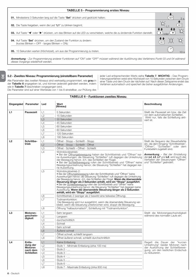
DE
6 – Deutsch
TABELLE 6 - Funktionen zweites Niveau
Eingangsled Parameter Led Wert Beschreibung (Niveau)
L1 L1
L2
L3
L4
L5
L6
L7
L8
5 Sekunden
15 Sekunden
30 Sekunden
45 Sekunden
60 Sekunden
80 Sekunden
120 Sekunden
180 Sekunden
Stellt die Pausezeit ein bzw. die Zeit vor dem automatischen Schließen. Wirkt nur, falls die Schließung akti-viert ist.
Pausezeit
L2 L1
L2
L3
L4
L5
L6
L7
L8
Öffnet - Stopp – Schließt - Stopp
Öffnet - Stopp – Schließt - Öffnet
Öffnet - Schließt – Öffnet - Schließt
Wohnblockbetrieb: • Bei der Öffnungsbewegung haben der Schrittbetrieb und “Öffnen” kei-ne Auswirkungen; die Steuerung “Schließen” ruft dagegen die Umkehrung der Bewegung hervor, d.h. das Schließen der Flügel. • Bei der Schließbewegung rufen der Schrittbetrieb und “Öffnen” keine Be wegungsumkehrung hervor; die Steuerung “Schließen” hat dagegen kei-ne Auswirkung.
Wohnblockbetrieb 2: • Bei der Öffnungsbewegung rufen der Schrittbetrieb und “Öffnen” keine Au swirkungen hervor; die Steuerung “Schließen” ruft dagegen die Umkehrung der Bewegung hervor, d.h. das Schließen der Flügel. Wenn die über sendete Steuerung länger als 2 Sekunden anhält, wird ein “Stopp” ausgeführt.• Bei der Schließbewegung rufen der Schrittbetrieb und “öffnen” keine Bewegungsumkehrung hervor; die Steuerung “Schließen” hat dagegen keine Auswirkung. Wenn die übersendete Steuerung länger als 2 Sekunden anhält, wird ein “Stopp” ausgeführt.
Schrittbetrieb 2 (weniger als 2 bewirkt eine teilweise Öffnung).
Todmannfunktion: Die Bewegung wird nur ausgeführt, wenn die übersendete Steuerung ver-bleibt; wenn die Steuerung unterbrochen wird, stoppt die Bewegung.
Öffnung “halbautomatisch”, Schließung mit “Todmannfunktion”.
Stellt die Sequenz der Steuerbefehle ein, die dem Eingang “Schrittbetrieb”, “Öffnen”, “Schließen” oder dem Funkbefehl zugeteilt sind.
Anmerkung – Bei der Einstellung der L4, L5, L7 und L8, wird auch das Verhalten der Steuerungen “Öffnen” und “Schließen” geändert.
Schrittbe-trieb
L3 L1
L2
L3
L4
L5
L6
L7
L8
Sehr langsam
Langsam
durchschnittlich
Schnell
Sehr schnell
Äußerst schnell
Öffnet schnell, schließt langsam
Öffnet äußerst schnell, schließt durchschnittlich
Stellt die Motorengeschwindigkeit während des normalen Laufs ein.
Motoren-geschwin-digkeit
L4 L1
L2
L3
L4
L5
L6
L7
L8
Keine Entladung
Stufe 1 - Minimale Entladung (zirka 100 ms)
Stufe 2 - …
Stufe 3 - …
Stufe 4 - …
Stufe 5 - …
Stufe 6 - …
Stufe 7 - Maximale Entladung (zirka 800 ms)
Regelt die Dauer der “kurzen Umkehrung” beider Motoren nach der Ausführung der Schließbewe-gung, um den restlichen Endschub zu reduzieren.
Entla-dung der Motoren nach dem Schließen
TABELLE 5 - Programmierung erstes Niveau
01. Mindestens 3 Sekunden lang auf die Taste “Set” drücken und gedrückt halten;
02. Die Taste freigeben, wenn die Led “L1” zu blinken beginnt;
03. Auf Taste “ ” oder “ ” drücken, um das Blinken auf die LED zu verschieben, welche die zu ändernde Funktion darstellt;
04. Auf Taste “Set” drücken, um den Zustand der Funktion zu ändern: (kurzes Blinken = OFF - langes Blinken = ON);
05. 10 Sekunden warten (Höchstzeit), um aus der Programmierung zu treten.
Anmerkung – Zur Programmierung anderer Funktionen auf “ON” oder “OFF” müssen während der Ausführung des Verfahrens Punkt 03 und 04 während dieses Vorgangs wiederholt werden.
SET
SET
SETL1
oder
3 s
10 s
5.2 - Zweites Niveau: Programmierung (einstellbare Parameter)
Alle Parameter des zweiten Niveaus sind werkseitig programmiert, wie grau in der Tabelle 6 angegeben ist, und können jederzeit geändert werden, indem wie in Tabelle 7 beschrieben vorgegangen wird.Die Parameter sind auf einer Wertskala von 1 bis 8 einstellbar, zur Prüfung des
jeder Led entsprechenden Werts siehe Tabelle 7. WICHTIG – Das Program-mierungsverfahren weist eine Höchstzeit von 10 Sekunden zwischen dem Druck einer Taste und dem Druck der nächsten auf. Nach dieser Zeitspanne endet das Verfahren automatisch und speichert die bisher ausgeführten Änderungen.
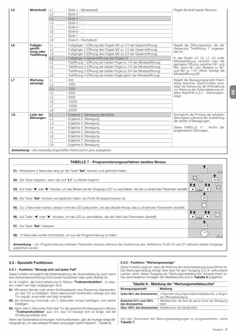
DE
Deutsch – 7
TABELLE 7 - Programmierungsverfahren zweites Niveau
01. Mindestens 3 Sekunden lang auf die Taste “Set” drücken und gedrückt halten;
02. Die Taste freigeben, wenn die Led “L1” zu blinken beginnt;
03. Auf Taste “ ” oder “ ” drücken, um das Blinken auf die “Eingangs-LED” zu verschieben, die den zu ändernden Parameter darstellt;
04. Die Taste “Set” drücken und gedrückt halten, bis Punkt 06 abgeschlossen ist;
05. Ca. 3 Sekunden warten, danach wird die LED aufleuchten, die das aktuelle Niveau des zu ändernden Parameters darstellt;
06. Auf Taste “ ” oder “ ” drücken, um die LED zu verschieben, die den Wert des Parameters darstellt;
07. Die Taste “Set” loslassen;
08. 10 Sekunden warten (Höchstzeit), um aus der Programmierung zu treten.
Anmerkung – Zur Programmierung mehrerer Parameter müssen während der Ausführung des Verfahrens Punkt 03 und 07 während dieses Vorgangs wiederholt werden.
SET
SET
SET
SETL1
oder
oder
3 s
10 s
5.3 - Spezielle Funktionen
5.3.1 - Funktion: “Bewegt sich auf jeden Fall”
Diese Funktion ermöglicht die Inbetriebsetzung der Automatisierung, auch we nn eine Sicherheitsvorrichtung nicht korrekt funktioniert oder außer Betrieb ist.
Es ist möglich, die Automatisierung im Modus “Todmannfunktion”, zu steu-ern, indem wie folgt vorgegangen wird:
01. Mit einem Sender oder einem Schlüsseltaster eine Steuerung übersenden, um das Tor zu betätigen. Wenn alles korrekt funktioniert, bewegt sich das Tor regulär, ansonsten wie folgt vorgehen;
02. die Schaltung innerhalb von 3 Sekunden erneut betätigen und weiter betätigen;
03. Nach zirka 2 Sekunden führt das Tor die gewünschte Bewegung im Modus “Todmannfunktion” aus; d.h. das Tor bewegt sich so lange, wie die Schaltung betätigt wird.
Wenn die Sicherheitsvorrichtungen nicht funktionieren, gibt die Anzeige einige Bli-n ksignale ab, um das erfasste Problem anzuzeigen (siehe Kapitel 6 - Tabelle 9).
5.3.2 - Funktion: “Wartungsanzeige”
Diese Funktion zeigt an, dass die Wartung der Automatisierung auszuführen ist. Die Wartungsmeldung erfolgt über eine mit dem Ausgang S.C.A. verbundene Lampe, wenn dieser Ausgang als “Wartungsmeldeleuchte” programmiert ist. Die verschiedenen Anzeigen der Meldeleuchte sind in Tabelle 8 aufgeführt.
Um den Grenzwert der Wartungsbewegungen zu programmieren, siehe Ta belle 7.
Tabelle 8 - Meldung der “Wartungsmeldeleuchte”
Bewegungsanzahl Meldung
2 Sekunden lang eingeschaltete Meldeleuchte, zu Beginn der Öffnungsbewegung
Meldeleuchte, die über die ganze Dauer der Bewegung blinkt
Meldeleuchte, die ständig blinkt.
Unter 80% des Grenzwertes
Zwischen 81% und 100% des Grenzwertes
Über 100% des Grenzwertes
Anmerkung – Die werkseitig eingestellten Werte sind in grau angegeben.
L8 L1
L2
L3
L4
L5
L6
L7
L8
Ergebnis 1. Bewegung (die letzte)
Ergebnis 2. Bewegung
Ergebnis 3. Bewegung
Ergebnis 4. Bewegung
Ergebnis 5. Bewegung
Ergebnis 6. Bewegung
Ergebnis 7. Bewegung
Ergebnis 8. Bewegung
Ermöglicht die Prüfung der erfolgten Störungsart während der Ausführung der letzten 8 Bewegungen.
Siehe TABELLE 11 - Archiv der aufgetretenen Störungen.
Liste der Störungen
L7 L1
L2
L3
L4
L5
L6
L7
L8
500
1000
1500
2500
5000
10000
15000
20000
Regelt die Bewegungsanzahl Wenn diese Nummer überschritten wird, ze i gt die Steuerung die Anforderung zur Wartung der Automatisierung an, siehe Abschnitt 5.3.2. - Wartungsan-zeige.
Wartung-sanzeige
L6 L1
L2
L3
L4
L5
L6
L7
L8
Fußgänger 1 (Öffnung des Flügels M2 zu 1/4 der Gesamtöffnung)
Fußgänger 2 (Öffnung des Flügels M2 zu 1/2 der Gesamtöffnung)
Fußgänger 3 (Öffnung des Flügels M2 zu 3/4 der Gesamtöffnung)
Fußgänger 4 (Gesamtöffnung des Flügels 2)
Teilöffnung 1 (Öffnung der beiden Flügel zu 1/4 der Mindestöffnung)
Teilöffnung 2 (Öffnung der beiden Flügel zu 1/2 der Mindestöffnung)
Teilöffnung 3 (Öffnung der beiden Flügel zu 3/4 der Mindestöffnung)
Teilöffnung 4 (Öffnung der beiden Flügel gleich der Mindestöffnung)
Regelt die Öffnungsweise, die der Steuerung “Teilöffnung 1” zugewie-sen ist.
In den Stufen L5, L6, L7, L8; unter Min destöffnung versteht man die geringere Öffnung zwischen M1 und M2; wenn M1 zum Beispiel zu 90° und M2 zu 110° öffnet, beträgt die Mindestöf f nung 90°
Fußgän-geröff-nung oder Teilöffnung
L5 L1
L2
L3
L4
L5
L6
L7
L8
Stufe 1 - Mindestkraft
Stufe 2 - …
Stufe 3 - …
Stufe 4 - …
Stufe 5 - …
Stufe 6 - …
Stufe 7 - …
Stufe 8 - Höchstkraft
Regelt die Kraft beider Motoren.Motorkraft

DE
8 – Deutsch
5.4 - Löschen des Speichers
Um das Archiv der Steuerung zu löschen und alle Werkseinstellungen erneut zu erhalten, wie folgt vorgehen: Die Tasten “ ” und “ ” drücken und gedrückt halten, bis die Leds L1 und L2 zu blinken beginnen.
Einige Vorrichtungen sind vorgerüstet, um Meldungen abzugeben, mit denen die Erkennung des Betriebszustands oder eventueller Störungen möglich ist.Wenn am Ausgang FLASH in der Steuerung eine Blinkleuchte angeschlossen wird, blinkt diese während einer Bewegung mit Abständen von 1 Sekunde. Wenn Störungen auftreten, blinkt die Blinkleuchte mit kürzeren Abständen, die-se werden zweimal wiederholt und sind von einer 1 Sekunden langen Pause ge trennt. In der Tabelle 9 sind die Ursache und die Lösung für jede Anzeigeart beschrieben.Auch die Leds in der Steuerung geben Meldungen ab; in de Tabelle 10 sind die Ursache und die Lösung für jede Anzeigeart beschrieben.Es ist möglich, die eventuell aufgetretenen Störungen während der Ausführung der letzten 8 Bewegungen zu kontrollieren, Bezugnahme: Tabelle 11.
WAS TUN, WENN ...(Leitfaden zum Lösen von Problemen)6
7-Mal kurzes Blinken1 Sekunde Pause7-Mal kurzes Blinken
Störung in den Stromkreisen Mindestens 30 Sekunden warten und den Befehl erneut erteilen und eventuell die Speisung ausschalten; sollte dieser Status bleiben, könnte ein schwerer Defekt vorhanden sein, und die elektronische Steuerkarte muss ausgewechselt werden.
8-Mal kurzes Blinken1 Sekunde Pause8-Mal kurzes Blinken
Es wurde bereits ein Befehl erteilt, so dass andere Befehle nicht ausgeführt werden können.
Die Art des vorhandenen Befehls überprüfen. Es könnte sich zum Beispiel um einen Befehl durch eine Uhr am Eingang “Öffnet” handeln.
9-Mal kurzes Blinken1 Sekunde Pause9-Mal kurzes Blinken
Die Automatisierung wurde durch eine Steuerung “Sperre Automatisierung” blockiert.
Die Automatisierung lösen, indem eine Steuerung “Lösen Automatisier-ung” übersendet wird.
10-Mal kurzes Blinken1 Sekunde Pause10-Mal kurzes Blinken
Eingriff der Funktion “Hinderniserfas-sung” durch Encoder
Während der Bewegung wurde die Motoren durch eine höhere Reibung blockiert, die Ursache prüfen.
TABELLE 10 - Meldungen der Blinkleuchte (FLASH)
Blinken Problem Lösung
1-Mal kurzes Blinken1 Sekunde Pause1-Mal kurzes Blinken
Fehler im System Bluebus Die Überprüfung der an BlueBUS angeschlossenen Vorrichtungen, die zu Beginn der Bewegung ausgeführt wird, entspricht nicht den während der Erlernung gespeicherten Vorrichtungen. Es ist möglich, dass getrennte oder gestörte Vorrichtungen vorliegen, somit prüfen und ersetzen. Wenn Änderungen vorgenommen wurden, muss die Erlernung der Vorrichtun-gen erneut ausgeführt werden (siehe Abschnitt 3.4).
2-Mal kurzes Blinken1 Sekunde Pause2-Mal Schnellblinken
Auslösung einer Lichtschranke Eine oder mehrere Lichtschranken geben keine Zustimmung zur Bewe-gung oder haben während des Laufs eine Bewegungsumkehrung hervor-gerufen; prüfen, ob Hindernisse vorliegen.
3-Mal kurzes Blinken1 Sekunde Pause3-Mal kurzes Blinken
Eingriff der Funktion “Hinderniserfassung” durch KraftbegrenzerWährend der Bewegung haben die Motoren eine höhere Kraft angetroffen; die Ursache prüfen und eventuell das Kraftniveau der Motoren erhöhen
4-Mal kurzes Blinken1 Sekunde Pause4-Mal kurzes Blinken
Auslösung des Eingangs STOPP Am Anfang oder während der Bewegung erfolgte eine Auslösung der mit dem Eingang STOP verbundenen Vorrichtungen; Ursache überprüfen.
5-Mal kurzes Blinken1 Sekunde Pause5-Mal kurzes Blinken
Fehler in den internen Parametern der Steuerung
Mindestens 30 Sekunden warten und den Befehl erneut erteilen und eventuell die Speisung ausschalten; sollte dieser Status bleiben, könnte ein schwerer Defekt vorhanden sein, und die elektronische Steuerkarte muss ausgewechselt werden.
6-Mal kurzes Blinken1 Sekunde Pause6-Mal kurzes Blinken
Die Höchstgrenze an aufeinander folgenden Bewegungen pro Stunde wurde überschritten.
Ein paar Minuten warten, bis der Bewegungsbegrenzer wieder unter die Höchstgrenze zurückkehrt.
TABELLE 11 - Meldungen der Leds in der Steuerung (Abb. 7)
Led Problem Lösung
BLUEBUSImmer aus
Immer ein
1 Mal Blinken pro Sekunde
2 Mal kurzes Blinken
Mehrmaliges Blinken mit Pausevon 1 Sekunde
Störung
Schwere Störung
Alle regulär
Statusvariation der Eingänge
Verschiedenes
Prüfen, ob die Steuerung gespeist ist; prüfen, ob die Sicherungen einge-griffen haben. In diesem Fall die Ursache des Defekts überprüfen, dann die Sicherungen mit anderen mit demselben Stromwert auswechseln
Es liegt ein schwerwiegendes Problem vor: Versuchen, die Steuerung von der Stromspeisung zu trennen und wenn der Zustand verbleibt, muss die elektronische Karte ersetzt werden
Regulärer Funktion der Steuerung
Regulär, wenn eine Änderung in einem der Eingänge erfolgt (PP, STOP, OPEN, CLOSE): Eingriff der Lichtschranken oder Übertragung einer Steue-rung mit einem Sender
Bezugnahme: Tabelle 9
STOPImmer aus
Immer ein
Die am Eingang STOPP angeschlosse-nen Vorrichtungen greifen ein
Alle regulär
Die Vorrichtungen des Eingangs STOPP prüfen
Eingang STOPP aktiv
P.P.Immer ausImmer ein
Alle regulär
Eingriff des Eingangs PP
Eingang P.P. nicht aktiv
Regulär, wenn die am Eingang PP angeschlossene Vorrichtung aktiv ist
OPENImmer ausImmer ein
Alle regulär
Eingriff des Eingangs OPEN
Eingang OPEN nicht aktiv
Regulär, wenn die am Eingang OPEN angeschlossene Vorrichtung aktiv ist
CLOSEImmer aus
Immer ein
Alle regulär
Eingriff des Eingangs CLOSE
Eingang CLOSE nicht aktiv
Regulär, wenn die am Eingang CLOSE angeschlossene Vorrichtung aktiv ist
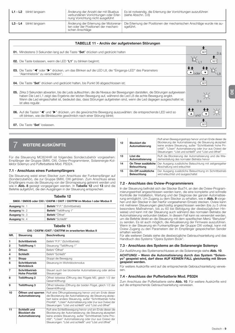
DE
Deutsch – 9
TABELLE 11 - Archiv der aufgetretenen Störungen
01. Mindestens 3 Sekunden lang auf die Taste “Set” drücken und gedrückt halten
02. Die Taste loslassen, wenn die LED “L1” zu blinken beginnt;
03. Die Taste “ ” oder “ ” drücken, um das Blinken auf die LED L8, die “Eingangs-LED” des Parameters “Alarmhistorik“ zu verschieben”;
04. Die Taste “Set” drücken und gedrückt halten, bis Punkt 06 abgeschlossen ist;
05. Zirka 3 Sekunden abwarten, bis die Leds aufleuchten, die die Niveaus der Bewegungen darstellen, die Störungen aufgewiesen haben Die Led L1 zeigt das Ergebnis der letzten Bewegung auf, während die Led L8 die achte Bewegung angibt.
Wenn die Led eingeschaltet ist, bedeutet das, dass Störungen aufgetreten sind, wenn die Led dagegen ausgeschaltet ist, ist alles regulär.
06. Auf die Tasten “ ” und “ ” drücken, um die gewünschte Bewegung auszuwählen: die entsprechende LED wird so oft blinken, wie die Blinkleuchte gewöhnlich nach einer Störung blinkt;
07. Die Taste “Set” loslassen.
SET
SET
SET
SETL1
oder
und
3 s
3 s
L8
L1 - L2 blinkt langsam Änderung der Anzahl der mit Bluebus verbundenen Vorrichtungen oder Erler-nung Vorrichtung nicht ausgeführt
Es ist notwendig, die Erlernung der Vorrichtungen auszuführen (siehe Abschn. 3.6)
L3 - L4 blinkt langsam Änderung der Erlernung der Motorenar-ten oder der Positionen der mechani-schen Anschläge
Die Erlernung der Positionen der mechanischen Anschläge wurde nie au-sgeführt.
Tabelle 13
OXI / OXIFM /OXIT / OXITFM im erweiterten Modus II
NR. Steuerung Beschreibung
Für die Steuerung MC824HR ist folgendes Sonderzubehör vorgesehen: Empfänger der Gruppe SMXI, OXI, Oview-Programmierer, Solarenergie-Kol-lektor Solemyo und Pufferbatterie Mod. PS324.
7.1 - Anschluss eines Funkempfängers
Die Steuerung weist einen Stecker zum Anschluss der Funkempfänger auf (Sonderzubehör), die zur Gruppe SMXI, OXI gehören. Zum Anschluss eines Empfängers muss die Steuerung von der Stromspeisung getrennt werden und wie in Abb. 8 gezeigt vorgegangen werden. In Tabelle 12 und 13 sind die Befehle aufgeführt, die den Ausgängen in der Steuerung entsprechen.
WEITERE AUSKÜNFTE7
Tabelle 12
SMXI / SMXIS oder OXI / OXIFM / OXIT / OXITFM im Modus I oder Modus II
Befehl “P.P.” (Schrittbetrieb)
Befehl “Teilöffnung 1”
Befehl “Öffnet”
Befehl “Schließt”
Ausgang Nr. 1
Ausgang Nr. 2
Ausgang Nr. 3
Ausgang Nr. 4
1 Schrittbetrieb
2 Teilöffnung 1
3 Öffnen
4 Schließt
5 Stopp
6 Schrittbetrieb Wohnblock
7 Schrittbetrieb Hohe Priorität
8 Teilöffnung 2
9 Teilöffnung 3
10 Öffnen und sperren Automatisierung
11 Schließt und Blockiert die Automatisierung
7.2 - Anschluss des Oview-Programmierers
In der Steuerung befindet sich der Stecker BusT4, an den die Oview-Program-mierungseinheit angeschlossen werden kann, die eine komplette und schnelle Kontrolle der Installation, Wartung und der Diagnose der ganzen Automatisie-rung ermöglicht. Um Zugang zu dem Stecker zu erhalten, wie in Abb. 9 vorge-hen und den Stecker in den hierfür vorgesehenen Einsatz stecken. Oview kann mit mehreren Steuerungen gleichzeitig angeschlossen werden (bis zu 5 ohne besondere Maßnahmen, bis zu 60 bei Befolgung der diesbezüglichen Hin-weise) und kann mit der Steuerung auch während des normalen Betriebs der Automatisierung verbunden bleiben. In diesem Fall kann es verwendet werden, um die Befehle direkt an die Steuerung mit dem spezifischen Menü “Benutzer” zu senden. Es ist auch möglich, die Aktualisierung der Firmware auszuführen. Wenn in der Steuerung ein Funkempfänger der Gruppe OXI vorliegt, kann mit Oview Zugang zu den Parametern der im Empfänger gespeicherten Sender erhalten werden.Für alle weiteren Details siehe die diesbezügliche Gebrauchsanleitung und das Handbuch des Systems “Opera System Book”.
7.3 - Anschluss des Systems an die Solarenergie Solemyo
Zur Ausführung des Systemanschlusses an die Solarenergie siehe Abb. 10.
ACHTUNG! – Wenn die Automatisierung durch das System “Solem-yo” gespeist wird, darf diese AUF KEINEN FALL gleichzeitig mit Strom ge speist werden.
Für weitere Auskünfte wird auf die entsprechende Gebrauchsanleitung verwie-sen.
7.4 - Anschluss der Pufferbatterie Mod. PS324
Zum Anschluss der Pufferbatterie siehe Abb. 10. Für weitere Auskünfte wird auf die entsprechende Gebrauchsanleitung verwiesen.
Befehl “P.P.” (Schrittbetrieb)
Steuerung “Teilöffnung 1”
Befehl “Öffnet”
Befehl “Schließt”
Stoppt die Bewegung
Steuerung im Wohnblockmodus
Steuert auch bei blockierter Automatisierung oder aktive Steuerungen
Öffnet teilweise (Öffnung des Flügels M2, gleich 1/2 der Gesamtöffnung)
Öffnet teilweise (Öffnung der beiden Flügel, gleich 1/2 der Gesamtöffnung)
Ruft eine Öffnungsbewegung hervor und am Ende dieser die Blockierung der Automatisierung; die Steuerung akzep-tiert keine andere Steuerung, außer “Schrittbetrieb hohe Priorität”, “Lösen” Automatisierung oder (nur aus Oview) der Steuerungen: “Löst und schließt” und “Löst und öffnet”
Ruft eine Schließbewegung hervor und am Ende dieser die Blockierung der Automatisierung; die Steuerung akzeptiert keine andere Steuerung, außer “Schrittbetrieb hohe Prio-rität”, “Lösen” Automatisierung oder (nur aus Oview) der Steuerungen: “Löst und schließt” und “Löst und öffnet”
12 Blockiert die Automatisierung
13 Löst die Automatisierung
14 On Timer zusätzliche Beleuchtung
15 On-Off zusätzliche Beleuchtung
Ruft einen Bewegungsstopp hervor und am Ende dieser die Blockierung der Automatisierung; die Steuerung ak zeptiert keine andere Steuerung, außer “Schrittbetrieb ho he Pri-orität”, “Lösen” Automatisierung oder (nur aus Ovi ew) der Steuerungen: “Löst und schließt” und “Löst und öffnet”
Ruft die Blockierung der Automatisierung und die Wie-derherstellung des normalen Betriebs hervor
Der Ausgang zusätzliche Beleuchtung mit zeitgeregelter Abschaltung wird erleuchtet
Der Ausgang zusätzliche Beleuchtung im Schrittbetrieb wird erleuchtet und ausgeschaltet
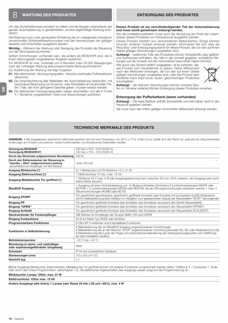
DE
10 – Deutsch
HINWEISE: • Alle angegebenen technischen Merkmale beziehen sich auf eine Temperatur von 20°C (± 5°C). • Nice S.p.a. behält sich das Recht vor, jederzeit als nötig betrachtete Änderungen am Produkt vorzunehmen, wobei Funktionalitäten und Einsatzzweck beibehalten werden.
Versorgung MC824HR 230 Vac (+10% -15%) 50/60 Hz Versorgung MC824HR/V1 120 Vac (+10% -15%) 50/60 Hz
Durch das Stromnetz aufgenommene Nennleistung 200 W
Durch den Batteriestecker der Steuerung in - “standby – Alles” aufgenommene Leistung Unter 100 mW (einschließlich ein Empfänger mit SM-Stecker)
Ausgang Blinkleuchte [*] für 1 Blinkleuchte LUCYB (Glühbirne 12 V, 21 W)
Ausgang Elektroschloss [*]: 1 Elektroschloss 12 Vac, max. 15 VA
Ausgang Meldeleuchte Tor geöffnet [*] 1 Glühbirne 24 V max. 4 W (die Ausgangsspannung kann zwischen 30 und +50% variieren, der Ausgang kann auch
kleine Relais steuern)
1 Ausgang mit einer Höchstbelastung von 15 Bluebus-Einheiten (höchstens 6 Lichtschrankenpaare MOFB oder BlueBUS Ausgang MOFOB + 2 Lichtschrankenpaare MOFB oder MOFOB, die als Öffnungsvorrichtungen adressiert werden + max. 4 Steuervorrichtungen MOMB oder MOTB
Eingang STOPP Für gewöhnlich geschlossene, gewöhnlich geöffnete Kontakte oder Kontakte mit konstantem 8,2KΩ Widerstand;
wird in Selbsterlernung (eine Variation im Vergleich zum gespeicherten Status) der Steuerbefehl “STOP” hervorgerufen
Eingang PP Für gewöhnlich geöffnete Kontakte (das Schließen des Kontaktes verursacht den Schritt-Steuerbefehl)
Eingang “OPEN” Für gewöhnlich geöffnete Kontakte (das Schließen des Kontaktes verursacht den Steuerbefehl ÖFFNET)
Eingang Schließt Für gewöhnlich geöffnete Kontakte (das Schließen des Kontaktes verursacht den Steuerbefehl SCHLIESST)
Steckverbinder für Funkempfänger SM-Stecker für Empfänger der Gruppe SMXI, OXI und OXIFM
Eingang Funkantenne 50 Ω für Kabel Typ RG58 oder ähnliche
Programmierbare Funktionen 8 ON-OFF-Funktionen und 8 einstellbare Funktionen
• Selbsterlernung der am BlueBUS Ausgang angeschlossenen Vorrichtungen
Funktionen in Selbsterlernung • Selbsterlernung der an der Klemme “STOP” angeschlossenen Vorrichtung (Kontakt NO, NC oder Widerstand 8,2 kΩ) • Selbsterlernung des Laufs der Flügel und automatische Kalkulierung der Verlangsamungspunkte und Teilöffnung (je nach Installation anders)
Betriebstemperatur - 20 °C bis + 50 °C
Benutzung in säure- und salzhaltiger NEIN
oder explosionsgefährdeter Umgebung
Schutzart IP 54 bei unversehrtem Gehäuse
Abmessungen (mm) 310 x 232 x H 122
Gewicht (kg) 4,1
[*] Die Ausgänge Blinkleuchte, Elektroschloss, Meldeleuchte Tor geöffnet können mit anderen Funktionen programmiert werden (siehe “TABELLE 4 – Funktionen 1. Stufe oder durch den Oview-Programmierer, siehe Kapitel 7.2). Die elektrischen Eigenschaften des Ausgangs passen aufgrund der Programmierung an:
Blinkleuchte: Lampe 12Vdc, max. 21 W
Elektroschloss: 12Vac max. 15 VA
Andere Ausgänge (alle Arten): 1 Lampe oder Relais 24 Vdc (-30 und +50%), max. 4 W
TECHNISCHE MERKMALE DES PRODUKTS
WARTUNG DES PRODUKTES8Um das Sicherheitsniveau konstant zu halten und die längste Lebensdauer der ganzen Automatisierung zu gewährleisten, ist eine regelmäßige Wartung erfor-derlich.
Die Wartung muss unter genauester Einhaltung der im vorliegenden Handbuch verzeichneten Sicherheitsbestimmungen und der Verordnungen der gültigen Gesetze und Vorschriften ausgeführt werden.
Wichtig – Während der Wartung oder Reinigung des Produkts die Steuerung von der Stromspeisung trennen.
Sollten Vorrichtungen vorhanden sein, die anders als MC824HR sind, die in Ihrem Wartungsplan vorgesehenen Angaben ausführen.Für MC824HR ist max. innerhalb von 6 Monaten oder 20.000 Bewegungen nach der vorherigen Wartung eine programmierte Wartung erforderlich:Zur Ausführung der Wartung wie folgt vorgehen: 01. Alle elektrischen Versorgungsquellen, inklusive eventuelle Pufferbatterien
abtrennen. 02. Die Verschlechterung aller Materialen der Automatisierung überprüfen, mit
besonderer Beachtung von Erosions- oder Roststellen an strukturellen Tei-len; Teile, die nicht genügend Garantie geben, müssen ersetzt werden.
03. Die elektrischen Versorgungsquellen wieder anschließen und alle in Punkt 4.1 Abnahme vorgesehenen Tests und Überprüfungen ausführen.
ENTSORGUNG DES PRODUKTES
Dieses Produkt ist ein vervollständigender Teil der Automatisierung und muss somit gemeinsam entsorgt werden.Wie die Installationsarbeiten muss auch die Abrüstung am Ende der Leben-sdauer dieses Produktes von Fachpersonal ausgeführt werden.Dieses Produkt besteht aus verschiedenen Materialarten: Einige können recycelt, anderen müssen entsorgt werden. Informieren Sie sich über die Recycling- oder Entsorgungssysteme für dieses Produkt, die von den auf Ihrem Gebiet gültigen Verordnungen vorgesehen sind.Achtung! – bestimmte Teile des Produktes können Schadstoffe oder gefährli-che Substanzen enthalten, die, falls in die Umwelt gegeben, schädliche Wir-kungen auf die Umwelt und die menschliche Gesundheit haben könnten.Wie durch das Symbol seitlich angegeben, ist es verboten, die-ses Produkt zum Haushaltmüll zu geben. Daher differenziert nach den Methoden entsorgen, die von den auf Ihrem Gebiet gültigen Verordnungen vorgesehen sind, oder das Produkt dem Verkäufer beim Kauf eines neuen, gleichwertigen Produktes zurückgeben.Achtung! – die örtlichen Verordnungen können schwere Stra-fen im Fall einer widerrechtlichen Entsorgung dieses Produktes vorsehen.
Entsorgung der Pufferbatterie (wenn vorhanden)
Achtung! – Die leere Batterie enthält Schadstoffe und darf daher nicht in den Hausmüll gegeben werden.
Sie muss nach den örtlich gültigen Vorschriften differenziert entsorgt werden.
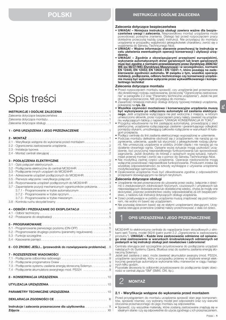
PL
Polski – 1
POLSKI
Spis treściINSTRUKCJE I OGÓLNE ZALECENIA . . . . . . . . . . . . . . . . . . . . . . . . . . . 1Zalecenia dotyczące bezpieczeństwa . . . . . . . . . . . . . . . . . . . . . . . . . . . . . . 1Zalecenia dotyczące montażu . . . . . . . . . . . . . . . . . . . . . . . . . . . . . . . . . . . . 1Zalecenia dotyczące obsługi . . . . . . . . . . . . . . . . . . . . . . . . . . . . . . . . . . . . . 1
1 - OPIS URZĄDZENIA I JEGO PRZEZNACZENIE . . . . . . . . . . . . . . . . . 1
2 - MONTAŻ . . . . . . . . . . . . . . . . . . . . . . . . . . . . . . . . . . . . . . . . . . . . . . . . 12.1 - Weryfikacje wstępne do wykonania przed montażem . . . . . . . . . . . . . . 12.2 - Ograniczenia zastosowania urządzenia . . . . . . . . . . . . . . . . . . . . . . . . . 22.3 - Instalacja typowa. . . . . . . . . . . . . . . . . . . . . . . . . . . . . . . . . . . . . . . . . . 22.4 - Montaż centrali sterującej . . . . . . . . . . . . . . . . . . . . . . . . . . . . . . . . . . . 2
3 - PODŁĄCZENIA ELEKTRYCZNE. . . . . . . . . . . . . . . . . . . . . . . . . . . . . . 23.1 - Opis połączeń elektrycznych . . . . . . . . . . . . . . . . . . . . . . . . . . . . . . . . . 23.2 - Podłączenia elektryczne do centrali MC824HR . . . . . . . . . . . . . . . . . . . 33.3 - Podłączenie innych urządzeń do MC824HR . . . . . . . . . . . . . . . . . . . . . 33.4 - Adresowanie urządzeń podłączonych do MC824HR. . . . . . . . . . . . . . . 33.5 - Pierwsze włączenie i weryfikacja połączeń. . . . . . . . . . . . . . . . . . . . . . . 33.6 - Rozpoznawanie urządzeń podłączonych do MC824HR . . . . . . . . . . . . 33.7 - Zapamiętanie pozycji mechanicznych ograniczników położenia. . . . . . . 3 3.7.1 - Programowanie w trybie automatycznym . . . . . . . . . . . . . . . . . 4 3.7.2 - Programowanie w trybie ręcznym . . . . . . . . . . . . . . . . . . . . . . . 4 3.7.3 - Programowanie w trybie mieszanym . . . . . . . . . . . . . . . . . . . . . 43.8 - Kontrola ruchu skrzydeł bramy . . . . . . . . . . . . . . . . . . . . . . . . . . . . . . . 4
4 - ODBIÓR I PRZEKAZANIE DO EKSPLOATACJI . . . . . . . . . . . . . . . . . 44.1 - Odbiór techniczny . . . . . . . . . . . . . . . . . . . . . . . . . . . . . . . . . . . . . . . . . 54.2 - Przekazanie do eksploatacji . . . . . . . . . . . . . . . . . . . . . . . . . . . . . . . . . 5
5 - PROGRAMOWANIE. . . . . . . . . . . . . . . . . . . . . . . . . . . . . . . . . . . . . . . . 55.1 - Programowanie pierwszego poziomu (ON-OFF) . . . . . . . . . . . . . . . . . . 55.2 - Programowanie drugiego poziomu (parametry regulowane). . . . . . . . . . 65.3 - Funkcje szczególne . . . . . . . . . . . . . . . . . . . . . . . . . . . . . . . . . . . . . . . . 75.4 - Kasowanie pamięci . . . . . . . . . . . . . . . . . . . . . . . . . . . . . . . . . . . . . . . . 8
6 - CO ZROBIC JEŚLI... (przewodnik do rozwiązywania problemów). . 8
7 - ROZSZERZENIE WIADOMOŚCI . . . . . . . . . . . . . . . . . . . . . . . . . . . . . 97.1 - Podłączenie odbiornika radiowego . . . . . . . . . . . . . . . . . . . . . . . . . . . . 97.2 - Podłączenie programatora Oview . . . . . . . . . . . . . . . . . . . . . . . . . . . . . 97.3 - Podłączenie systemu zasilania energią słoneczną Solemyo . . . . . . . . . . 97.4 - Podłączenie akumulatora awaryjnego mod. PS324 . . . . . . . . . . . . . . . 9
8 - KONSERWACJA URZĄDZENIA . . . . . . . . . . . . . . . . . . . . . . . . . . . . . 10
UTYLIZACJA URZĄDZENIA. . . . . . . . . . . . . . . . . . . . . . . . . . . . . . . . . . . 10
PARAMETRY TECHNICZNE URZĄDZENIA . . . . . . . . . . . . . . . . . . . . . . 10
DEKLARACJA ZGODNOŚCI CE . . . . . . . . . . . . . . . . . . . . . . . . . . . . . . . III
Instrukcje i zalecenia przeznaczone dla użytkownika . . . . . . . . . . . . . . XZdjęcia . . . . . . . . . . . . . . . . . . . . . . . . . . . . . . . . . . . . . . . . . . . . . . . . . . . XII
MC824HR to elektroniczna centrala do napędzania bram skrzydłowych z silni-kami serii Toona, model 5624I (patrz punkt 2.2 „Ograniczenia w zastosowaniu produktu”). UWAGA! – Każde inne zastosowanie odmienne od opisane-go oraz zastosowanie w warunkach środowiskowych odmiennych od podanych w tej instrukcji obsługi jest niewłaściwe i zabronione!
Centrala sterująca jest szczególnie przystosowana do podłączania urządzeń należących do Systemu Opera, Bluebus oraz do systemu zasilania energią sło-neczną Solemyo.Jeżeli jest zasilana z sieci, może zawierać akumulator awaryjny (mod. PS324, urządzenie opcjonalne), który w przypadku przerwy w dopływie energii elek-trycznej gwarantuje automatyce wykonanie kilku manewrów w ciągu następ-nych kilku godzin.Pozostałe akcesoria to odbiorniki przystosowane do podłączenia dzięki obec-ności w centrali złącza “SM” (SMXI, OXI, itp.).
OPIS URZĄDZENIA I JEGO PRZEZNACZENIE1
Zalecenia dotyczące bezpieczeństwa• UWAGA! – Niniejsza instrukcja obsługi zawiera ważne dla bezpie-
czeństwa uwagi i zalecenia. Nieprawidłowy montaż urządzenia może powodować poważne zranienia. Dlatego też przed rozpoczęciem pracy dokładnie przeczytaj każdą część instrukcji. Nie przystępuj do montażu urządzenia w przypadku wątpliwości jakiegokolwiek charakteru; zwróć się o wyjaśnienia do Serwisu Technicznego Nice.
• UWAGA! – Ważne informacje: starannie przechowuj tę instrukcję w celu ułatwienia ewentualnych operacji konserwacji i utylizacji urzą-dzenia.
• UWAGA! – Zgodnie z obowiązującymi przepisami europejskimi, wykona nie automatycznych drzwi garażowych lub bram garażowych musi być zgodne z normami przewidzianymi przez Dyrektywę 2006/42/WE (ex 98/37/WE) (Dyrektywa Maszynowa) i w szczególności, normami EN 12445; EN 12453; EN 12635 i EN 13241-1, które pozalają na zade-klarowanie zgodności automatu. W związku z tym, wszelkie operacje instalacji, podłączania, odbioru technicznego czy konserwacji urządze-nia muszą być wykonane wyłącznie przez wykwalifikowanego i kompe-tentnego technika!
Zalecenia dotyczące montażu• Przed rozpoczęciem montażu sprawdź, czy urządzenie jest przeznaczone
dla określonego rodzaju zastosowania, (przeczytaj “Ograniczenia zastosowa-nia” w paragrafie 2.2 oraz “Parametry techniczne urządzenia”). Jeżeli nie jest do niego przeznaczone, NIE przystępuj do montażu.
• Zawartość niniejszej instrukcji obsługi dotyczy typowej instalacji urządzenia, pokazanej na rys. 2a.
• Wszelkie czynności montażowe i konserwacyjne urządzenia muszą być wykonywane po odłączeniu automatyki od zasilania elektrycz-nego. Jeśli urządzenie wyłączające nie jest widoczne z miejsca, w którym umieszczono siłownik, przez rozpoczęciem pracy należy zawiesić na urządze-niu wyłączającym tablicę z napisem “UWAGA! KONSERWACJA W TOKU”.
• Przygotuj wbudowanie na linii zasilającej automatykę, prowadzącej z sieci elektrycznej, urządzenia rozłączającego zasilanie i gwarantującego odległość pomiędzy stykami, umożliwiającą całkowite rozłączenie w warunkach III kate-gorii przepięcia.
• Podłącz centralę do linii zasilania elektrycznego wyposażonej w uziemienie.• Podczas montażu delikatnie obchodź się z urządzeniem, nie narażaj go na
zgniecenia, uderzenia, upadki lub styczność z jakiegokolwiek rodzaju płyna-mi. Nie umieszczaj urządzenia w pobliżu źródeł ciepła i nie narażaj go na działanie otwartego ognia. Opisane wyżej sytuacje mogą uszkodzić urzą-dzenie, być przyczyną nieprawidłowego funkcjonowania lub spowodować zagrożenia. Jeżeli doszłoby do którejś z opisanych wyżej sytuacji, natych-miast przerwij montaż i zwróć się o pomoc do Serwisu Technicznego Nice.
• Nie modyfikuj żadnej części urządzenia. Operacje niedozwolone mogą wy łącznie powodować nieprawidłowe funkcjonowanie. Producent zrzeka się wszelkiej odpowiedzialności za szkody wynikające z używania urządzenia modyfikowanego samowolnie.
• Opakowanie urządzenia musi być zlikwidowane zgodnie z odpowiednimi przepisami obowiązującymi na danym terytorium.
Zalecenia dotyczące obsługi• Urządzenie nie jest przeznaczone do używania przez osoby, (włącznie z dzieć-
mi) o zredukowanych zdolnościach fizycznych, czuciowych i umysłowych lub nieposiadających doświadczenia lub dostatecznej wiedzy, chyba że mogły one skorzystać, poprzez pośrednictwo osoby odpowiedzialnej za ich bezpieczeń-stwo, z nadzoru lub instrukcji dotyczących obsługi urządzenia.
• Dzieci przebywające w pobliżu urządzenia muszą znajdować się pod nadzo-rem, nie wolno im bawić się urządzeniem.
• Nie pozwalaj dzieciom bawić się ze stałymi urządzeniami sterującymi. Urzą-dzenia sterujące przenośne (zdalne) należy przechowywać z dala od dzieci.
INSTRUKCJE I OGÓLNE ZALECENIA
2.1 - Weryfikacje wstępne do wykonania przed montażem
Przed przystąpieniem do montażu urządzenia sprawdź stan jego komponen-tów, sprawdź również, czy wybrany model jest odpowiedni oraz czy warunki otoczenia przeznaczonego do jego montażu są odpowiednie.• Sprawdź, czy wszystkie materiały, które zostaną zastosowane znajdują się w
ide alnym stanie i czy są odpowiednie do użycia zgodnego z ich przeznaczeniem.
MONTAŻ2

PL
2 – Polski
PODŁĄCZENIA ELEKTRYCZNE3Podłączenie elektryczne różnych urządzeń (fotokomórki, klawiatury cyfrowe, czytniki kart zbliżeniowych (transpondery), itp., występujących w automatyce z centralą sterującą, musi być wykonane z zastosowaniem systemu “Bluebus” firmy Nice.
3.1 - Opis połączeń elektrycznych (rys. 6)
ANTENA wejście dla anteny odbiornika radiowego
FLASH wyjście dla 1 lampy ostrzegawczej z żarówką 12 V (maksymalnie 21 W). [*]
ELS wyjście dla zamka elektrycznego 12 Vpp (maksymalnie 15 VA). [*]
S.C.A. “Kontrolka Stanu Bramy”: wyjście dla 1 lampy sygnalizującej 24 V, maksymalnie 4 W. [*]
BLUEBUS wejście dla urządzeń kompatybilnych (MOFB, MOFOB, MOB i MOTB; równoległe podłączenie urządzeń z zastosowaniem 2 prze-wodów, przez które przepływa zarówno zasilanie elektryczne jak i sygnały komunikacji; nie jest konieczne przestrzeganie biegunowo-ści. Połączenie elektryczne, które należy zastosować jest połącze-niem równoległym, które nie wymaga przestrzegania żadnej bie-gunowości. Podczas fazy rozpoznawania każde urządzenie podłą-czone do centrali zostanie przez nią rozpoznane pojedynczo, dzięki jednoznacznemu kodowi. Za każdym razem, kiedy zostanie dodane lub usunięte jakieś urządzenie, musisz ponownie przeprowadzić procedurę rozpoznawania (przeczytaj paragraf 3.6).
STOP wejście dla urządzeń, które swoim działaniem powodują natych-miastowe zatrzymanie wykonywanego manewru, po nim następuje krótka zmiana ruchu; możliwość połączenia styków typu NO, NC lub urządzeń z wyjściem o stałej oporności 8,2 kΩ (listwy rezystancyjne). Każde urządzenie podłączone do tego wejścia jest rozpoznawane
przez centralę podczas fazy rozpoznawania (paragraf 3.6). Jeżeli w czasie pracy centrala odczyta na tym wejściu jakąkolwiek zmianę w stosunku do stanu zapamiętanego przy programowaniu, natych-miast zatrzyma siłowniki (STOP).Możesz podłączyć do tego wejścia jedno lub kilka urządzeń, mogą to być również różne urządzenia:
– podłącz równolegle kilka urządzeń typu NO, bez ograniczenia ilo-ści;
– podłączenie seryjne dowolnej ilości urządzeń NC; – podłącz równolegle 2 urządzenia z wyjściem o stałej oporności
8,2 kΩ. W przypadku podłączenia więcej jak dwóch urządzeń musisz podłączyć je kaskadowo, stosując tylko jedną oporność końcową 8,2 kΩ;
– podłącz równolegle 2 urządzenia typu NO i NC, łącząc szerego-wo styk NC z opornością 8,2 kΩ (umożliwia to również kombi-nację pomiędzy 3 urządzeniami NO - NC i 8,2 kΩ)
P.P. wejście dla urządzeń sterujących, które poprzez swoje zadziałanie powodują wykonanie manewru w trybie Krok po Kroku; możliwość podłączenia styków typu NO
OPEN wejście dla urządzeń sterujących, które poprzez swoje zadziałanie powodują wykonanie manewru otwierania; możliwość podłączenia styków typu NO
CLOSE wejście dla urządzeń sterujących, które poprzez swoje zadziałanie powodują wykonanie tylko manewru zamykania; możliwość podłą-czenia styków typu NO
ENC1 wejście dla enkodera - motoreduktora 1 (zacisk 1, 2); nie należy przestrzegać żadnej biegunowości
ENC2 wejście dla enkodera - motoreduktora 2 (zacisk 4, 5); nie należy przestrzegać żadnej biegunowości
M1 wyjście dla motoreduktora 1 (zacisk 7, 8, 9)
M2 wyjście dla motoreduktora 2 (zacisk 10, 11, 12).
[*] Wyjścia FLASH, ELS i S.C.A. mogą być programowane z innymi funkcjami (patrz “TABELA 4 - Funkcje 1-go poziomu”; lub z zastosowaniem programato-ra Oview, przeczytaj rozdział 7.2).
• Sprawdź, czy wszystkie warunki eksploatacji wchodzą w zakres ograniczeń zastosowania urządzenia (paragraf 2.2) oraz w zakres wartości podanych w rozdziale “Parametry techniczne urządzenia”.
• Sprawdź, czy otoczenie wybrane do montażu urządzenia jest kompatybilne z jego całkowitymi wymiarami gabarytowymi (patrz rys. 1).
• Sprawdź, czy wybrana wstępnie powierzchnia, przeznaczona do montażu urządzenia jest trwała i może zagwarantować stabilne przymocowanie.
• Sprawdź, czy strefa mocowania urządzenia nie jest narażona na zalanie, ewentualnie zamontuj urządzenie na odpowiedniej wysokości nad ziemią.
• Sprawdź, czy przestrzeń znajdująca się wokół urządzenia umożliwia łatwy i pewny dostęp do niego.
• Sprawdź, czy wszystkie zastosowane przewody elektryczne są typu poda-nego w Tabeli 1.
• Sprawdź, czy w automatyce znajdują się ograniczniki mechaniczne, funkcjo-nujące zarówno podczas zamykania jak i otwierania.
2.2 - Ograniczenia zastosowania urządzenia
Centrala MC824HR może być stosowana wyłącznie z siłownikami Toona, model 5624I. Silniki te są nawrotne: oznacza to, iż można przesuwać ręcznie bramy skrzydła, bez konieczności ręcznego wysprzęglania siłownika. Dzięki umieszczonemu w silniku czujnikowi centrala może wykrywać ręczne przesu-wanie skrzydeł, a ponadto prawidłowo sterować kolejnymi manewrami. Ma to na celu niedopuszczenie do uderzenia skrzydeł bramy o ograniczniki mecha-niczne otwierania i zamykania. Uwaga! – Jeżeli centrala nie jest prawidłowo zasilana prądem lub jeżeli aktywna jest funkcja „Standby wszystko”, ręczne przesuwanie skrzydeł bramy nie jest wykrywane.
2.3 - Instalacja typowa
Na rys. 2a przedstawiona jest przykładowa instalacja automatu, wykonana z zastosowaniem komponentów firmy Nice:a - centrala sterującab - Motoreduktorc - Lampa ostrzegawcza
d - Fotokomórkae - Klawiatura cyfrowa - Czytnik kart zbliżeniowych - Przełącznik kluczowyf - Słupek do montażu fotokomórkig - Ograniczniki mechaniczne otwieraniah - Ograniczniki mechaniczne zamykaniai - Zamek elektryczny
Te komponenty są rozmieszczone zgodnie z typowym i powszechnie stoso-wanym schematem. Nawiązując do rys. 2a, ustal przybliżone położenie, w którym zostanie zainstalowane każde urządzenie przewidziane w tej instalacji. Ważne – Przed wykonaniem montażu przygotuj odpowiednie przewody elek-tryczne niezbędne dla Twojej instalacji, nawiązując do rys. 2b oraz do “Tabeli 1 - Parametry techniczne kabli elektrycznych”.Uwaga – Podczas układania osłon umożliwiających przeprowadzenie przewo-dów elektrycznych i doprowadzenie ich do centrali, uwzględnij, że w wyniku możliwego gromadzenia się wody w puszkach rozgałęźnych, osłony łączące mogą powodować powstawanie zjawisk kondensatu wewnątrz centrali, w wyniku których może nastąpić uszkodzenie obwodów elektronicznych.
2.4 - Montaż centrali sterującej
Aby przymocować centralę sterującą postępuj jak pokazano na rys. 3:01. Otwórz obudowę centrali wykręcając specjalne śruby (rys. 3-A);02. Wykonaj otwory umożliwiające przeprowadzenie przewodów elektrycz-
nych (rys. 3-B);03. Przykręć obudowę (rys. 3-C);04. Teraz jest możliwe wykonanie podłączeń elektrycznych: patrz rozdz. 3. Uwaga! – Aby móc włożyć osłony przewodów elektrycznych, musisz wywier-cić otwory w dolnej ściance obudowy centrali. Uwaga – Jeżeli to konieczne możesz wykorzystać boczne wejście dla przewodów ale tylko w przypadku zastosowania odpowiednich złączek przeznaczonych dla osłon kablowych - w celu uszczelnienia połączenia.Aby dokonać montażu innych urządzeń występujących w automatyce odwołaj się do odpowiednich instrukcji obsługi.
Podłączenie Rodzaj przewodu Maksymalna dozwolona długość
A: Przewód ZASILANIA CENTRALI STERUJĄCEJ 1 przewód 3 x 1,5 mm2 30 m (uwaga 1)
B: Przewód LAMPY OSTRZEGAWCZEJ z anteną 1 przewód 2 x 0,5 mm2 20 m 1 przewód koncentryczny, ekranowany typu RG58 20 m (zalecany jest przewód krótszy od 5 m)
C: Przewód URZĄDZEŃ BLUEBUS 1 przewód 2 x 0,5 mm2 20 m (uwaga 2)
D: Przewód PRZEŁĄCZNIKA KLUCZOWEGO 2 przewody 2 x 0,5 mm2 (uwaga 3) 50 m
E: Przewód ZASILANIA MOTOREDUKTORA 1 przewód 3 x 1,5 mm2 (uwaga 4) 10 m
F: Przewód PODŁĄCZENIA ENKODERA 1 przewód 2 x 1 mm2 (uwaga 4) 10 m
G: Przewód do PODŁĄCZENIA ZAMKA ELEKTRYCZNEGO 1 przewód 2 x 1 mm2 10 m
Uwaga 1 – Jeśli przewód zasilania przekracza 30 m długości należy zastosować przewód o większym przekroju (3 x 2,5 mm2) i zainstalować uziemienie ochronne w pobliżu siłowników.Uwaga 2 – Jeśli przewód Bluebus przekracza 20 m długości (maksymalna długość przewodu 40 m), należy wykorzystać przewód o większym przekroju (2 x 1 mm2).Uwaga 3 – Te dwa przewody mogą zostać zastąpione jednym przewodem 4 x 0,5 mm2.Uwaga 4 – Te dwa przewody mogą zostać zastąpione jednym przewodem 5 x 0,5 mm2.
UWAGA! – Zastosowane przewody muszą być przeznaczone dla typu otoczenia, w którym następuje ich montaż.
TABELA 1 - Parametry techniczne przewodów elektrycznych (rys. 2b)
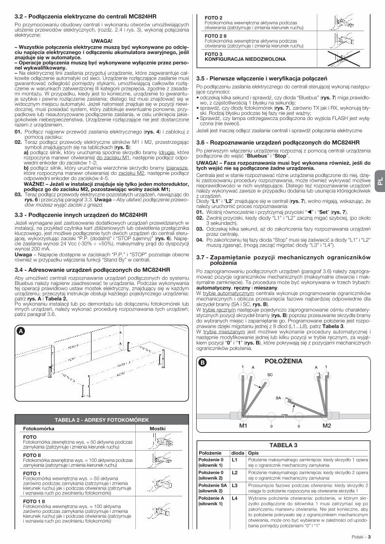
PL
Polski – 3
3.5 - Pierwsze włączenie i weryfikacja połączeń
Po podłączeniu zasilania elektrycznego do centrali sterującej wykonaj następu-jące czynności:• odczekaj kilka sekund i sprawdź, czy dioda “Bluebus” (rys. 7) miga prawidło-
wo, z częstotliwością 1 błysku na sekundę;• sprawdź, czy diody fotokomórek (rys. 7), zarówno TX jak i RX, wykonują bły-
ski. Rodzaj błysku podczas tej fazy nie jest ważny;• Sprawdź, czy lampa ostrzegawcza podłączona do wyjścia FLASH jest wyłą-
czona (nie świeci).
Jeżeli jest inaczej odłącz zasilanie centrali i sprawdź połączenia elektryczne
3.6 - Rozpoznawanie urządzeń podłączonych do MC824HR
Po pierwszym włączeniu urządzenia rozpoznaj z pomocą centrali urządzenia podłączone do wejść “Bluebus” i “Stop”.
UWAGA! – Faza rozpoznawania musi być wykonana również, jeśli do tych wejść nie są podłączone żadne urządzenia.
Centrala jest w stanie rozpoznawać różne urządzenia podłączone do niej, dzię-ki zastosowaniu procedury rozpoznawania, może również wykrywać możliwe nieprawidłowości w nich występujące. Dlatego też rozpoznawanie urządzeń należy wykonywać zawsze w przypadku dodania lub usunięcia któregokolwiek z urządzeń.Diody “L1” i “L2” znajdujące się w centrali (rys. 7), wolno migają, wskazując, że należy uruchomić proces rozpoznawania:01. Wciśnij równocześnie i przytrzymaj przyciski “ ” i “Set” (rys. 7).02. Zwolnij przyciski, kiedy diody “L1” i “L2” zaczną migać szybciej, (po około
3 sekundach).03. Odczekaj kilka sekund, aż do zakończenia fazy rozpoznawania urządzeń
przez centralę.04. Po zakończeniu tej fazy dioda “Stop” musi się zaświecić a diody “L1” i “L2”
muszą zgasnąć, (mogą zacząć migotać diody “L3” i “L4”).
3.7 - Zapamiętanie pozycji mechanicznych ograniczników położenia
Po zaprogramowaniu podłączonych urządzeń (paragraf 3.6) należy zaprogra-mować pozycje ograniczników mechanicznych (maksymalne otwarcie i mak-symalne zamknięcie). Ta procedura może być wykonywana w trzech trybach: automatyczny, ręczny i mieszany.W trybie automatycznym centrala wykonuje programowanie ograniczników mechanicznych i oblicza przesunięcia fazowe najbardziej odpowiednie dla skrzydeł bramy (SA i SC, rys. B).W trybie ręcznym następuje pojedynczo zaprogramowanie ośmiu charaktery-stycznych pozycji skrzydeł bramy (rys. B) poprzez przesuwanie skrzydła bramy do wybranych miejsc i zapamiętanie go. Programowane położenie jest rozpo-znawane dzięki migotaniu jednej z 8 diod (L1...L8), patrz Tabela 3.W trybie mieszanym jest możliwe wykonanie procedury automatycznej i następnie modyfikowanie jednej lub kilku pozycji w trybie ręcznym, za wyjąt-kiem pozycji “0” i “1” (rys. B), które pokrywają się z pozycjami mechanicznych ograniczników położenia.
3.2 - Podłączenia elektryczne do centrali MC824HR
Po przymocowaniu obudowy centrali i wykonaniu otworów umożliwiających ułożenie przewodów elektrycznych, (rozdz. 2.4 i rys. 3), wykonaj połączenia elektryczne:
UWAGA!– Wszystkie połączenia elektryczne muszą być wykonywane po odcię-ciu napięcia elektrycznego i odłączeniu akumulatora awaryjnego, jeśli znajduje się w automatyce. – Operacje połączenia muszą być wykonywane wyłącznie przez perso-nel wykwalifikowany.– Na elektrycznej linii zasilania przygotuj urządzenie, które zagwarantuje cał-kowite odłączenie automatyki od sieci. Urządzenie rozłączające zasilanie musi gwarantować odległość pomiędzy stykami, umożliwiającą całkowite rozłą-czenie w warunkach zatwierdzonej III kategorii przepięcia, zgodnie z zasada-mi montażu. W przypadku, kiedy jest to konieczne, urządzenie to gwarantu-je szybkie i pewne rozłączenie zasilania; dlatego też musi znajdować się w widocznym miejscu automatyki. Jeżeli natomiast znajduje się w pozycji niewi-docznej, musi posiadać system, który zablokuje ewentualne ponowne, przy-padkowe lub nieautoryzowane podłączenie zasilania, w celu uniknięcia jakie-gokolwiek niebezpieczeństwa. Urządzenie rozłączające nie jest dostarczone razem z urządzeniem.
01. Podłącz najpierw przewód zasilania elektrycznego (rys. 4) i zablokuj z pomocą zacisku;
02. Teraz podłącz przewody elektryczne silników M1 i M2, przestrzegając symboli znajdujących się na tabliczkach (rys. 5):
a) podłącz silnik, który uruchamia spodnie skrzydło bramy (drugie, które rozpoczyna manewr otwierania) do zacisku M1, następnie podłącz odpo-wiedni enkoder do zacisków 1-2;
b) podłącz silnik, który uruchamia wierzchnie skrzydło bramy (pierwsze, które rozpoczyna manewr otwierania) do zacisku M2, następnie podłącz odpowiedni enkoder do zacisków 4-5.
WAŻNE! – Jeżeli w instalacji znajduje się tylko jeden motoreduktor, podłącz go do zacisku M2, pozostawiając wolny zacisk M1;
03. Teraz podłącz przewody elektryczne pozostałych urządzeń, nawiązując do rys. 6 i przeczytaj paragraf 3.3. Uwaga – Aby ułatwić podłączenie przewo-dów możesz wyjąć zaciski z gniazd.
3.3 - Podłączenie innych urządzeń do MC824HR
Jeżeli wymagane jest zastosowanie dodatkowych urządzeń przewidzianych w instalacji, na przykład czytnika kart zbliżeniowych lub oświetlenia przełącznika kluczowego, jest możliwe podłączenie tych dwóch urządzeń do centrali steru-jącej, wykorzystując zaciski “P.P. (dodatni)” i “STOP (ujemny)” (rys. 6). Napię-cie zasilania wynosi 24 Vcc (-30% ÷ +50%), maksymalny prąd do dyspozycji wynosi 200 mA.Uwaga – Napięcie dostępne w zaciskach “P.P.” i “STOP” pozostaje obecne ró w nież w przypadku włączenia funkcji “Stand By” w centrali.
3.4 - Adresowanie urządzeń podłączonych do MC824HR
Aby umożliwić centrali rozpoznawanie urządzeń podłączonych do systemu Bluebus należy najpierw zaadresować te urządzenia. Podczas wykonywania tej operacji prawidłowo ustaw mostek elektryczny, znajdujący się w każdym urządzeniu; przeczytaj instrukcje obsługi każdego pojedynczego urządzenia: patrz rys. A i Tabela 2. Po wykonaniu instalacji lub po demontażu lub dołączeniu fotokomórek lub innych urządzeń, należy wykonać procedurę rozpoznawania tych urządzeń; patrz paragraf 3.6.
A
TABELA 2 - ADRESY FOTOKOMÓREK
Fotokomórka Mostki
FOTO Fotokomórka zewnętrzna wys. = 50 aktywna podczas zamykania (zatrzymuje i zmienia kierunek ruchu)
FOTO II Fotokomórka zewnętrzna wys. = 100 aktywna podczas zamykania (zatrzymuje i zmienia kierunek ruchu)
FOTO 1 Fotokomórka wewnętrzna wys. = 50 aktywna zarówno podczas zamykania (zatrzymuje i zmienia kierunek ruchu) jak i podczas otwierania (zatrzymuje i wznawia ruch po zwolnieniu fotokomórki)
FOTO 1 II Fotokomórka wewnętrzna wys. = 100 aktywna zarówno podczas zamykania (zatrzymuje i zmienia kierunek ruchu) jak i podczas otwierania (zatrzymuje i wznawia ruch po zwolnieniu fotokomórki)
FOTO 2 Fotokomórka wewnętrzna aktywna podczas otwierania (zatrzymuje i zmienia kierunek ruchu)
FOTO 2 II Fotokomórka wewnętrzna aktywna podczas otwierania (zatrzymuje i zmienia kierunek ruchu)
FOTO 3 KONFIGURACJA NIEDOZWOLONA
0
1 1A
SC
SA
A
0M1 M2
B POŁOŻENIA
TABELA 3
Położenie dioda Opis
Położenie 0(siłownik 1)
Położenie 0(siłownik 2)
Położenie SA(siłownik 2)
Położenie A(siłownik 1)
Położenie maksymalnego zamknięcia: kiedy skrzydło 1 opiera się o ogranicznik mechaniczny zamykania
Położenie maksymalnego zamknięcia: kiedy skrzydło 2 opiera się o ogranicznik mechaniczny zamykania
Przesunięcie fazowe podczas otwierania: kiedy skrzydło 2 osiąga to położenie rozpoczyna się otwieranie skrzydła 1
Wybrane położenie otwierania: położenie, w którym skr-zy dło podłączone do siłownika 1 musi zatrzymać się po zakończeniu manewru otwierania. Nie jest konieczne, aby to położenie pokrywało się z ogranicznikiem mechanicznym otwierania, może ono być wybierane w zależności od upodo-bania pomiędzy położeniami “0” i “1”
L1
L2
L3
L4
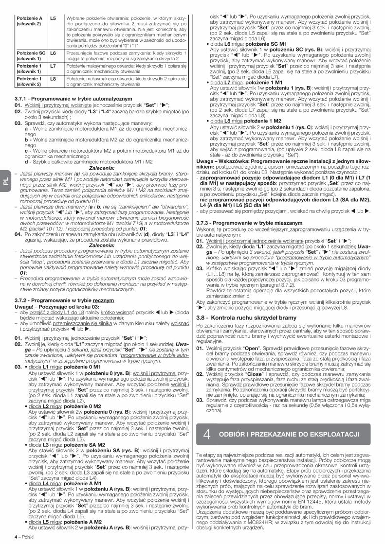
PL
4 – Polski
3.7.1 - Programowanie w trybie automatycznym01. Wciśnij i przytrzymaj wciśnięte jednocześnie przyciski “Set” i “ ”;02. Zwolnij przyciski kiedy diody “L3“ i “L4“ zaczną bardzo szybko migotać (po
około 3 sekundach) ;03. Sprawdź, czy automatyka wykona następujące manewry: a - Wolne zamknięcie motoreduktora M1 aż do ogranicznika mechanicz-
nego b - Wolne zamknięcie motoreduktora M2 aż do ogranicznika mechanicz-
nego c - Wolne otwarcie motoreduktora M2 a potem motoreduktora M1 aż do
ogranicznika mechanicznego d - Szybkie całkowite zamknięcie motoreduktora M1 i M2
Zalecenia:– Jeżeli pierwszy manewr (a) nie powoduje zamknięcia skrzydła bramy, stero-
wanego przez silnik M1 i powoduje natomiast zamknięcie skrzydła sterowa-nego przez silnik M2, wciśnij przycisk “ ” lub “ ”, aby przerwać fazę pro-gramowania. Teraz zamień połączenia silników M1 i M2 na zaciskach znaj-dujących się w centrali oraz połączenia odpowiednich enkoderów, następnie rozpocznij procedurę od punktu 01;
– Jeżeli pierwsze dwa manewry (a i b) nie są “zamknięciem” ale “otwarciem”, wciśnij przycisk “ ” lub “ ”, aby zatrzymać fazę programowania. Następnie w motoreduktorze, który wykonał manewr otwierania zamień biegunowość dwóch przewodów: w motoreduktorze M1 (zaciski 7 i 9) a w motoreduktorze M2 (zaciski 10 i 12), i rozpocznij procedurę od punktu 01;
04. Po zakończeniu manewru zamykania obu siłowników (d), diody “L3” i “L4” zgasną, wskazując, że procedura została wykonana prawidłowo.
Zalecenia:– Jeżeli podczas procedury programowania w trybie automatycznym zostanie
stwierdzone zadziałanie fotokomórek lub urządzenia podłączonego do wej-ścia “stop”, procedura zostanie przerwana a dioda L1 zacznie migotać. Aby ponownie uaktywnić programowanie należy wznowić procedurę od punktu 01;
– Procedura programowania w trybie automatycznym może zostać wznowio-na w dowolnej chwili, również po dokonaniu montażu; na przykład w następ-stwie zmiany pozycji ograniczników mechanicznych.
3.7.2 - Programowanie w trybie ręcznymUwaga! – Poczynając od kroku 03:– aby przejść z diody L1 do L8 należy krótko wcisnąć przycisk lub (dioda
będzie migotać wskazując aktualne położenie);– aby umożliwić przemieszczanie się silnika w danym kierunku należy wcisnąć
i przytrzymać przycisk lub .
01. Wciśnij i przytrzymaj jednocześnie przyciski “Set” i “ ”;02. Zwolnij je, kiedy dioda “L1” zaczyna migotać (po około 1 sekundzie); Uwa-
ga – Po upłynięciu 3 sekund, jeżeli przyciski “Set” i “ ” nie zostaną w tym czasie zwolnione, uaktywni się procedura “programowanie w trybie auto-matycznym” w zastępstwie programowania w trybie ręcznym.
03. • dioda L1 miga: położenie 0 M1 Aby ustawić siłownik 1 w położeniu 0 (rys. B): wciśnij i przytrzymaj przy-
cisk “ ” lub “ ”. Po uzyskaniu wymaganego położenia zwolnij przycisk, aby za trzymać wykonywany manewr. Aby wczytać położenie wciśnij i przytrzymaj przycisk “Set” przez co najmniej 3 sek. i następnie zwolnij, (po 2 sek. dioda L1 zapali się na stałe a po zwolnieniu przycisku “Set” zaczyna migać dioda L2).
• dioda L2 miga: położenie 0 M2 Aby ustawić siłownik 2w położeniu 0 (rys. B): wciśnij i przytrzymaj przy-
cisk “ ” lub “ ”. Po uzyskaniu wymaganego położenia zwolnij przycisk, aby za trzymać wykonywany manewr. Aby wczytać położenie wciśnij i przytrzymaj przycisk “Set” przez co najmniej 3 sek. i następnie zwolnij, (po 2 sek. dioda L2 zapali się na stałe a po zwolnieniu przycisku “Set” zaczyna migać dioda L3).
• dioda L3 miga: położenie SA M2 Aby stawić siłownik 2 w położeniu SA (rys. B): wciśnij i przytrzymaj
przycisk “ ” lub “ ”. Po uzyskaniu wymaganego położenia zwolnij przycisk, aby za trzymać wykonywany manewr. Aby wczytać położenie wciśnij i przytrzymaj przycisk “Set” przez co najmniej 3 sek. i następnie zwolnij, (po 2 sek. dioda L3 zapali się na stałe a po zwolnieniu przycisku “Set” zaczyna migać dioda L4).
• dioda L4 miga: położenie A M1 Aby ustawić siłownik 1 w położeniu A (rys. B): wciśnij i przytrzymaj przy-
cisk “ ” lub “ ”. Po uzyskaniu wymaganego położenia zwolnij przycisk, aby za trzymać wykonywany manewr. Aby wczytać położenie wciśnij i przytrzymaj przycisk “Set” przez co najmniej 3 sek. i następnie zwolnij, (po 2 sek. dioda L4 zapali się na stałe a po zwolnieniu przycisku “Set” zaczyna migać dioda L5).
• dioda L5 miga: położenie A M2 Aby ustawić siłownik 2 w położeniu A (rys. B): wciśnij i przytrzymaj przy-
Te etapy są najważniejsze podczas realizacji automatyki, ich celem jest zagwa-rantowanie maksymalnego bezpieczeństwa instalacji. Próby odbiorcze mogą być wykonywane również w celu przeprowadzenia okresowej kontroli urzą-dzeń, które składają się na automatykę. Etapy prób odbiorczych i przekazania automatyki do eksploatacji muszą być wykonywane przez personel wykwa-lifikowany i doświadczony, którego obowiązkiem jest ustalenie zakresu nie-zbędnych prób, mających na celu sprawdzenie rozwiązań zastosowanych w stosunku do występujących niebezpieczeństw oraz sprawdzenie przestrzega-nia zaleceń przewidzianych przez obowiązujące przepisy, normy i ustawy: w szczególności wszystkich wymogów normy EN 12445, która ustala metody wykonywania prób kontrolnych automatyki do bram.Urządzenia dodatkowe muszą być poddawane specyficznym próbom odbior-czym, zarówno pod względem funkcjonalności jak i ich prawidłowego wzajem-nego oddziaływania z MC824HR; w związku z tym odwołaj się do instrukcji obsługi konkretnych urządzeń.
ODBIÓR I PRZEKAZANIE DO EKSPLOATACJI4
cisk “ ” lub “ ”. Po uzyskaniu wymaganego położenia zwolnij przycisk, aby za trzymać wykonywany manewr. Aby wczytać położenie wciśnij i przytrzymaj przycisk “Set” przez co najmniej 3 sek. i następnie zwolnij, (po 2 sek. dioda L5 zapali się na stałe a po zwolnieniu przycisku “Set” zaczyna migać dioda L6).
• dioda L6 miga: położenie SC M1 Aby ustawić siłownik 1 w położeniu SC (rys. B): wciśnij i przytrzymaj
przycisk “ ” lub “ ”. Po uzyskaniu wymaganego położenia zwolnij przycisk, aby za trzymać wykonywany manewr. Aby wczytać położenie wciśnij i przytrzymaj przycisk “Set” przez co najmniej 3 sek. i następnie zwolnij, (po 2 sek. dioda L6 zapali się na stałe a po zwolnieniu przycisku “Set” zaczyna migać dioda L7).
• dioda L7 miga: położenie 1 M1 Aby ustawić siłownik 1w położeniu 1 (rys. B): wciśnij i przytrzymaj przy-
cisk “ ” lub “ ”. Po uzyskaniu wymaganego położenia zwolnij przycisk, aby za trzymać wykonywany manewr. Aby wczytać położenie wciśnij i przytrzymaj przycisk “Set” przez co najmniej 3 sek. i następnie zwolnij, (po 2 sek. dioda L7 zapali się na stałe a po zwolnieniu przycisku “Set” zaczyna migać dioda L8).
• dioda L8 miga położenie 1 M2 Aby ustawić siłownik 2 w położeniu 1 (rys. C): wciśnij i przytrzymaj przy-
cisk “ ” lub “ ”. Po uzyskaniu wymaganego położenia zwolnij przycisk, aby za trzymać wykonywany manewr. Aby wczytać położenie wciśnij i przytrzymaj przycisk “Set” przez co najmniej 3 sek. i następnie zwolnij, aby wyjść z programowania, (po upływie 2 sek. dioda L8 zapali się na stałe - aż do zwolnienia przycisku “Set”).
Uwaga – Wskazówka: Programowanie ręczne instalacji z jednym siłow-nikiem: postępować zgodnie z opisem umieszczonym na początku tego roz-działu, od kroku 01 do kroku 03. Następnie wykonać poniższe czynności:- zaprogramować pozycje odpowiadające diodom L1 (0 dla M1) i L7 (1
dla M1) w następujący sposób: przytrzymać przycisk „Set” przez co naj-mniej 3 s, następnie zwolnić go (po 2 sekundach dioda pozostanie zapalona, a po zwolnieniu przycisku „Set” kolejna dioda zacznie migać).
- nie programować pozycji odpowiadających diodom L3 (SA dla M2), L4 (A dla M1) i L6 (SC dla M1
- aby przesuwać się pomiędzy pozycjami, wciskać na chwilę przycisk lub .
3.7.3 - Programowanie w trybie mieszanymWykonaj tę procedurę po wcześniejszym zaprogramowaniu urządzenia w try-bie automatycznym:01. Wciśnij i przytrzymaj jednocześnie wciśnięte przyciski “Set” i “ ”;02. Zwolnij je, kiedy dioda “L1” zaczyna migotać (po około 1 sekundzie); Uwa-
ga – Po upłynięciu 3 sekund, jeżeli przyciski “Set” i “ ” nie zostaną zwol-nione, uaktywni się procedura “programowanie w trybie automatycznym” w zastępstwie programowania w trybie ręcznym.
03. Krótko wciskając przycisk “ ” lub “ ” zmień pozycję migającej diody (L1…L8) na tę, którą zamierzasz zaprogramować i kontynuuj w ten sam sposób dla każdej pojedynczej pozycji, jak opisano w kroku 03 programo-wania w trybie ręcznym (paragraf 3.7.2).
Powtórz tę ostatnią operację dla wszystkich pozostałych pozycji, które zamierzasz zmienić.
Aby zakończyć programowanie w trybie ręcznym wciśnij kilkakrotnie przycisk “ ”, aby zmienić pozycje migającej diody i przesunąć ją powyżej L8.
3.8 - Kontrola ruchu skrzydeł bramy
Po zakończeniu fazy rozpoznawania zaleca się wykonanie kilku manewrów otwiera nia i zamykania, sterowanych przez centralę, aby w ten sposób spraw-dzić po prawność ruchu bramy i wychwycić ewentualne usterki montażowe i regulacyjne.
01. Wciśnij przycisk “Open”. Sprawdź prawidłowe przesunięcie fazowe skrzy-deł bramy podczas otwierania, sprawdź również, czy podczas manewru otwierania występuje faza przyspieszania, faza ze stałą prędkością i faza zwalniania. Po zakończeniu manewru skrzydła bramy muszą zatrzymać się kilka centymetrów od mechanicznego ogranicznika otwierania;
02. Wciśnij przycisk “Close” i sprawdź, czy podczas manewru zamykania występuje faza przyspieszania, faza ruchu ze stałą prędkością i faza zwal-niania. Sprawdź prawidłowe przesunięcie fazowe skrzydeł bramy podczas zamykania. Po zakończeniu operacji skrzydła bramy muszą być perfekcyj-nie zamknięte, opierając się na ograniczniku mechanicznym zamykania;
03. Sprawdź, czy podczas wykonywania manewru lampa ostrzegawcza miga regularnie z częstotliwością - raz na sekundę (0,5s włączona i 0,5s wyłą-czona).
Położenie A(siłownik 2)
Położenie SC(siłownik 1)
Położenie 1(siłownik 1)
Położenie 1(siłownik 2)
Wybrane położenie otwierania: położenie, w którym skrzy-dło podłączone do siłownika 2 musi zatrzymać się po zakończeniu manewru otwierania. Nie jest konieczne, aby to położenie pokrywało się z ogranicznikiem mechanicznym otwierania, może ono być wybierane w zależności od upodo-bania pomiędzy położeniami “0” i “1”
Przesunięcie fazowe podczas zamykania: kiedy skrzydło 1 osiąga to położenie, rozpoczyna się zamykanie skrzydła 2
Położenie maksymalnego otwarcia: kiedy skrzydło 1 opiera się o ogranicznik mechaniczny otwierania
Położenie maksymalnego otwarcia: kiedy skrzydło 2 opiera się o ogranicznik mechaniczny otwierania
L5
L6
L7
L8
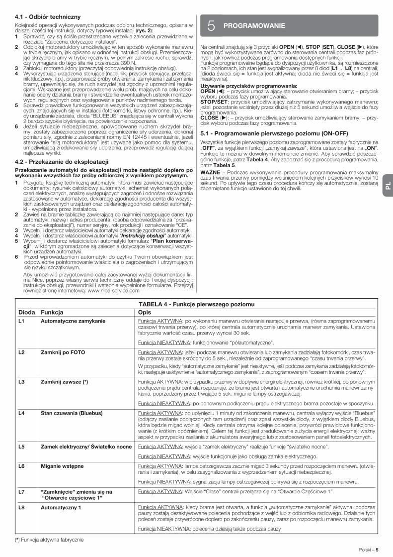
PL
Polski – 5
Na centrali znajdują się 3 przyciski OPEN ( ), STOP (SET), CLOSE ( ), które mogą być wykorzystywane zarówno do sterowania centrali podczas faz prób-nych, jak również podczas programowania dostępnych funkcji.Funkcje programowalne będące do dyspozycji użytkownika, są rozmieszczone na 2 poziomach, ich stan jest sygnalizowany przez 8 diod (L1 ... L8) na centrali, (dioda świeci się = funkcja jest aktywna; dioda nie świeci się = funkcja jest nieaktywna).
Używanie przycisków programowania:OPEN ( ): – przycisk umożliwiający sterowanie otwieraniem bramy; – przycisk wyboru podczas fazy programowania.STOP/SET: przycisk umożliwiający zatrzymanie wykonywanego manewru; jeżeli pozostanie wciśnięty przez dłużej niż 5 sekund umożliwia wejście do fazy programowania.CLOSE ( ): – przycisk umożliwiający sterowanie zamykaniem bramy; – przy-cisk wyboru podczas fazy programowania.
5.1 - Programowanie pierwszego poziomu (ON-OFF)
Wszystkie funkcje pierwszego poziomu zaprogramowane zostały fabrycznie na „OFF”, za wyjątkiem funkcji „zamykaj zawsze”, która ustawiona jest na „ON”. Funkcje te można w dowolnym momencie zmienić. Aby sprawdzić poszcze-gólne funkcje, patrz Tabela 4. Aby zapoznać się z procedurą programowania, patrz Tabela 5.
WAŻNE – Podczas wykonywania procedury programowania maksymalny czas trwania przerwy pomiędzy wciśnięciem kolejnych przycisków wynosi 10 sekund. Po upływie tego czasu procedura kończy się automatycznie, zostaną zapamiętane funkcje ustawione do tej chwili.
PROGRAMOWANIE5
TABELA 4 - Funkcje pierwszego poziomu
Dioda Funkcja Opis
L1 Automatyczne zamykanie
L2 Zamknij po FOTO
L3 Zamknij zawsze (*)
L4 Stan czuwania (Bluebus)
L5 Zamek elektryczny/ Światełko nocne
L6 Miganie wstępne
L7 “Zamknięcie” zmienia się na “Otwarcie częściowe 1”
L8 Automatyczny 1
Funkcja AKTYWNA: po wykonaniu manewru otwierania następuje przerwa, (równa zaprogramowanemu czasowi trwania przerwy), po której centrala automatycznie uruchamia manewr zamykania. Ustawiona fabrycznie wartość czasu przerwy wynosi 30 sek.
Funkcja NIEAKTYWNA: funkcjonowanie “półautomatyczne”.
Funkcja AKTYWNA: jeżeli podczas manewru otwierania lub zamykania zadziałają fotokomórki, czas trwa-nia przerwy zostaje skrócony do 5 sek., niezależnie od zaprogramowanego “czasu trwania przerwy”.
W przypadku, kiedy “automatyczne zamykanie” jest nieaktywne, jeśli podczas zamykania zadziałają fotokomór-ki, następuje uaktywnienie “automatycznego zamykania”, z zaprogramowanym “czasem trwania przerwy”.
Funkcja AKTYWNA: w przypadku przerwy w dopływie energii elektrycznej, również krótkiej, po ponownym podłączeniu prądu centrala rozpoznaje, że brama jest otwarta i automatycznie uruchamia manewr zamy-kania, poprzedzony przez trwające 5 sek. miganie lampy ostrzegawczej.
Funkcja NIEAKTYWNA: po ponownym podłączeniu prądu elektrycznego brama pozostaje w spoczynku.
Funkcja AKTYWNA: po upłynięciu 1 minuty od zakończenia manewru, centrala wyłączy wyjście “Bluebus” (odłączy zasilanie podłączonych tam urządzeń) oraz zgasi wszystkie diody, z wyjątkiem diody Bluebus, która będzie migać wolniej. Kiedy centrala otrzyma kolejne polecenie, przywróci prawidłowe funkcjono-wanie (z krótkim opóźnieniem). Celem tej funkcji jest zredukowanie zużycia energii elektrycznej; ważny aspekt w przypadku zasilania z akumulatora awaryjnego lub z zastosowaniem paneli fotoelektrycznych.
Funkcja AKTYWNA: wyjście “zamek elektryczny” realizuje funkcję “światełko nocne”.
Funkcja NIEAKTYWNA: wyjście funkcjonuje jako obsługa zamka elektrycznego.
Funkcja AKTYWNA: lampa ostrzegawcza zacznie migać 3 sekundy przed rozpoczęciem manewru (otwie-rania i zamykania), w celu zasygnalizowania z wyprzedzeniem sytuacji niebezpiecznej.
Funkcja NIEAKTYWNA: sygnalizacja lampy ostrzegawczej pokrywa się z rozpoczęciem manewru.
Funkcja AKTYWNA: Wejście “Close” centrali przełącza się na “Otwarcie Częściowe 1”.
Funkcja AKTYWNA: kiedy brama jest otwarta, a funkcja „automatyczne zamykanie” aktywna, podczas pauzy zostają dezaktywowane polecenia pochodzące z wejść lub z odbiornika radiowego. Działanie tych poleceń zostaje przywrócone dopiero po zakończeniu pauzy, zaraz po rozpoczęciu manewru zamykania.
Funkcja NIEAKTYWNA: polecenia działają także podczas pauzy
(*) Funkcja aktywna fabrycznie
4.1 - Odbiór techniczny
Kolejność operacji wykonywanych podczas odbioru technicznego, opisana w dalszej części tej instrukcji, dotyczy typowej instalacji (rys. 2):1 Sprawdź, czy są ściśle przestrzegane wszelkie zalecenia przewidziane w
rozdziale “Zalecenia dotyczące instalacji”.2 Odblokuj motoreduktory umożliwiając w ten sposób wykonanie manewru
w trybie ręcznym, jak opisano w odnośnej instrukcji obsługi. Przemieszcza-jąc skrzydło bramy w trybie ręcznym, w pełnym zakresie ruchu, sprawdź, czy wymagana do tego siła nie przekracza 390 N.
3 Zablokuj motoreduktory (przeczytaj odpowiednią instrukcję obsługi).4 Wykorzystując urządzenia sterujące (nadajnik, przycisk sterujący, przełącz-
nik kluczowy, itp.), przeprowadź próby otwierania, zamykania i zatrzymania bramy, upewniając się, że ruch skrzydeł jest zgodny z uprzednimi regula-cjami. Wskazane jest przeprowadzenie wielu prób, mających na celu doko-nanie oceny działania bramy i stwierdzenie ewentualnych usterek montażo-wych, regulacyjnych oraz występowanie punktów nadmiernego tarcia.
5 Sprawdź prawidłowe funkcjonowanie wszystkich urządzeń zabezpieczają-cych, znajdujących się w instalacji (fotokomórki, listwy ochronne, itp.). Kie-dy urządzenie zadziała, dioda “BLUEBUS” znajdująca się w centrali wykona 2 bardzo szybkie błyśnięcia, na potwierdzenie rozpoznania.
6 Jeżeli sytuacje niebezpieczne, spowodowane ruchem skrzydeł bra-my, zostały zabezpieczone poprzez ograniczenie siły uderzenia, dokonaj pomiaru siły, zgodnie z zaleceniami normy EN 12445 i ewentualnie, jeżeli sterowanie “siłą motoreduktora” jest używane jako pomoc dla systemu, umożliwiającą zredukowanie siły uderzenia, przeprowadź regulację dającą najlepsze wyniki.
4.2 - Przekazanie do eksploatacji
Przekazanie automatyki do eksploatacji może nastąpić dopiero po wykonaniu wszystkich faz próby odbiorczej z wynikiem pozytywnym.
1 Przygotuj książkę techniczną automatyki, która musi zawierać następujące dokumenty: rysunek całościowy automatyki, schemat wykonanych połą-czeń elektrycznych, analizę występujących zagrożeń i odnośne rozwiązania zastosowane w automatyce, deklarację zgodności producenta dla wszyst-kich zastosowanych urządzeń oraz deklarację zgodności całości automaty-ki - wypełnioną przez instalatora.
2 Zawieś na bramie tabliczkę zawierającą co najmniej następujące dane: typ automatyki, nazwę i adres producenta, (osoba odpowiedzialna za “przeka-zanie do eksploatacji”), numer seryjny, rok produkcji i oznakowanie “CE”.
3 Wypełnij i dostarcz właścicielowi automatyki deklarację zgodności automatyki.4 Wypełnij i dostarcz właścicielowi automatyki “Instrukcję obsługi” automatyki.5 Wypełnij i dostarcz właścicielowi automatyki formularz “Plan konserwa-
cji“, w którym zgromadzone są zalecenia dotyczące konserwacji wszyst-kich urządzeń automatyki.
6 Przed wprowadzeniem automatyki do użytku Twoim obowiązkiem jest odpowiednie poinformowanie właściciela o zagrożeniach i utrzymującym się ryzyku szczątkowym.
Aby umożliwić przygotowanie całej zacytowanej wyżej dokumentacji fir-ma Nice, poprzez własny serwis techniczny oddaje do Twojej dyspozycji: instrukcje obsługi, przewodniki i wstępnie wypełnione formularze. Przejrzyj również stronę internetową: www.nice-service.com

PL
6 – Polski
TABELA 6 - Funkcje drugiego poziomu
Dioda Parametr Dioda Wartość Opis wejścia (poziom)
L1 L1
L2
L3
L4
L5
L6
L7
L8
5 sekund
15 sekund
30 sekund
45 sekund
60 sekund
80 sekund
120 sekund
180 sekund
Reguluje czas trwania przerwy, czyli zwłokę przed zamknięciem automat-ycznym. Działa wyłącznie, jeśli “auto-matyczne zamknięcie” jest aktywne.
Czas trwania przerwy
L2 L1
L2
L3
L4
L5
L6
L7
L8
Otwarcie – stop – zamknięcie – stop
Otwarcie – stop – zamknięcie – otwarcie
Otwarcie – zamknięcie – otwarcie – zamknięcie
Zespół mieszkalny: • podczas manewru otwierania polecenie “Krok po kroku” i “Otwieranie” nie działają; natomiast polecenie “Zamykanie” powoduje zmianę ruchu, czyli zamknięcie bramy. • podczas manewru zamykania polecenie “Krok po kroku” i “Otwieranie” powodują zmianę ruchu, czyli otwarcie bramy; natomiast polecenie “Zamy-kanie” nie wywiera żadnego skutku.
Zespół mieszkalny 2: • podczas manewru otwierania polecenie “Krok po kroku” i “Otwieranie” nie działają; natomiast polecenie “Zamykanie” powoduje zmianę ruchu, czyli zamknięcie bramy. Jeżeli wysyłane polecenie trwa więcej niż 2 sekundy, brama przejdzie do stanu “Stop”. • podczas manewru zamykania polecenie “Krok po kroku” i “Otwieranie” powodują zmianę ruchu, czyli otwarcie bramy; natomiast polecenie “Zamy-kanie” nie działa. Jeżeli wysyłane polecenie trwa więcej niż 2 sekun-dy, brama przejdzie do stanu “Stop”.
Krok po kroku 2 (sygnał krótszy niż 2s daje otwarcie częściowe)
W obecności użytkownika: manewr odbywa się, dopóki wysłane polecenie jest podtrzymywane; jeżeli natomiast zostanie ono przerwane manewr zostanie zatrzymany.
otwieranie w trybie “półautomatycznym”, zamykanie “w obecności użytkownika”
Reguluje sekwencję poleceń połączonych z wejściem “Krok po Kroku”, “Otwieranie”, “Zamykanie” lub z po leceniem radiowym.
Uwaga – Ustawiając L4, L5, L7 i L8, ulega zmianie również zachowanie poleceń “Otwieranie” i “Zamykanie”.
Funkcja Krok po Kroku
L3 L1
L2
L3
L4
L5
L6
L7
L8
Bardzo niska
Niska
Średnia
Duża
Bardzo duża
Maksymalna
Otwieranie szybkie (L4), Zamykanie wolne (L2)
Otwieranie maksymalnie szybkie (L6), Zamykanie ze średnią prędkością (L3)
Reguluje prędkość silników podczas ruchu głównego.
Prędkość siłowników
L4 L1
L2
L3
L4
L5
L6
L7
L8
Brak odprężenia
Poziom 1 - Odprężenie minimalne (około 100 ms)
Poziom 2 - ...
Poziom 3 - ...
Poziom 4 - ...
Poziom 5 - ...
Poziom 6 - ...
Poziom 7 - Odprężenie maksymalne (około 800 ms)
Reguluje czas trwania “krótkiego re-wersu” w obu silnikach, po wykonaniu Zamknięcia, w celu zredukowania na-prę żenia w zamkniętej bramie.
Odprężenie siłowników po zamknięciu
TABELA 5 - Procedura programowania pierwszego poziomu
01. Wciśnij i przytrzymaj przycisk “Set” przez około 3 sekundy;
02. Zwolnij przycisk, kiedy dioda “L1” zacznie migać;
03. Wciskając przycisk “ ” lub “ ” przesuń migającą diodę na pozycję odpowiadającą funkcji, którą należy zmienić;
04. Wciśnij na krótki przycisk “Set” aby zmienić stan funkcji: (krótki błysk = OFF - długi błysk = ON);
05. Odczekaj 10 sekund (aż dioda przestanie migać), aby wyjść z programowania.
Uwaga – Aby zaprogramować inne funkcje na “ON” lub “OFF”, podczas wykonywania tej procedury można powtórzyć punkty 03 i 04 nie wychodząc z programowania.
SET
SET
SETL1
lub
3 s
10 s
5.2 - Programowanie drugiego poziomu (parametry regulowane)
Wszystkie parametry drugiego poziomu są wstępnie ustawione fabrycznie; są one zaznaczone szarym kolorem w Tabeli 6 i mogą być modyfikowane w każdej chwili, zgodnie z opisem zamieszczonym w Tabeli 7.Parametry są regulowane w skali od 1do 8; aby sprawdzić wartość
odpowiadającą każdej diodzie przejrzyj Tabelę 7. WAŻNE – Podczas wykony-
wania procedury programowania maksymalny czas trwania przerwy pomiędzy
wciśnięciem kolejnych przycisków wynosi 10 sekund. Po upływie tego czasu
procedura kończy się automatycznie i zostaną zapamiętane funkcje, ustawione
do tej chwili.
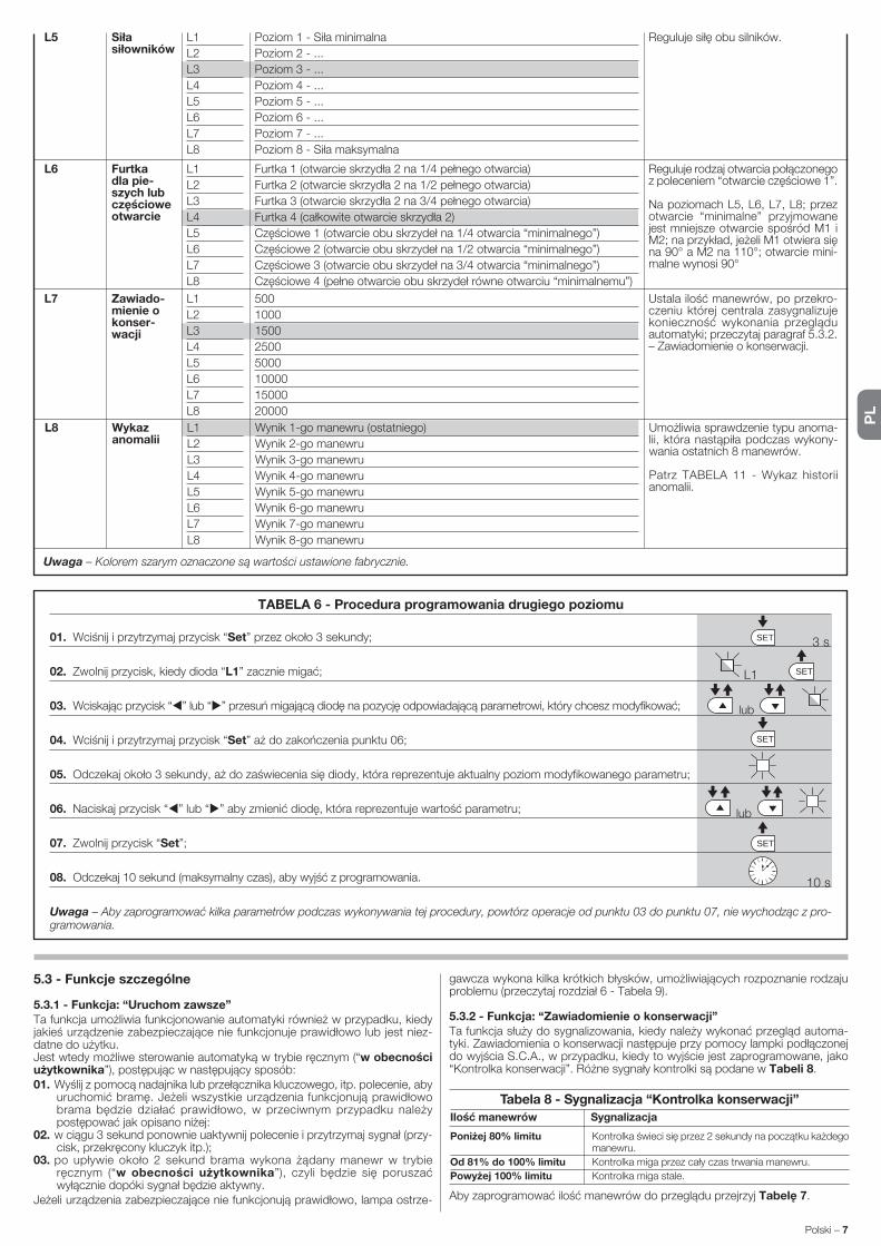
PL
Polski – 7
TABELA 6 - Procedura programowania drugiego poziomu
01. Wciśnij i przytrzymaj przycisk “Set” przez około 3 sekundy;
02. Zwolnij przycisk, kiedy dioda “L1” zacznie migać;
03. Wciskając przycisk “ ” lub “ ” przesuń migającą diodę na pozycję odpowiadającą parametrowi, który chcesz modyfikować;
04. Wciśnij i przytrzymaj przycisk “Set” aż do zakończenia punktu 06;
05. Odczekaj około 3 sekundy, aż do zaświecenia się diody, która reprezentuje aktualny poziom modyfikowanego parametru;
06. Naciskaj przycisk “ ” lub “ ” aby zmienić diodę, która reprezentuje wartość parametru;
07. Zwolnij przycisk “Set”;
08. Odczekaj 10 sekund (maksymalny czas), aby wyjść z programowania.
Uwaga – Aby zaprogramować kilka parametrów podczas wykonywania tej procedury, powtórz operacje od punktu 03 do punktu 07, nie wychodząc z pro-gramowania.
SET
SET
SET
SETL1
lub
lub
3 s
10 s
5.3 - Funkcje szczególne
5.3.1 - Funkcja: “Uruchom zawsze”Ta funkcja umożliwia funkcjonowanie automatyki również w przypadku, kiedy jakieś urządzenie zabezpieczające nie funkcjonuje prawidłowo lub jest niez-datne do użytku.Jest wtedy możliwe sterowanie automatyką w trybie ręcznym (“w obecności użytkownika”), postępując w następujący sposób:01. Wyślij z pomocą nadajnika lub przełącznika kluczowego, itp. polecenie, aby
uruchomić bramę. Jeżeli wszystkie urządzenia funkcjonują prawidłowo brama będzie działać prawidłowo, w przeciwnym przypadku należy postępować jak opisano niżej:
02. w ciągu 3 sekund ponownie uaktywnij polecenie i przytrzymaj sygnał (przy-cisk, przekręcony kluczyk itp.);
03. po upływie około 2 sekund brama wykona żądany manewr w trybie ręcznym (“w obecności użytkownika”), czyli będzie się poruszać wyłącznie dopóki sygnał będzie aktywny.
Jeżeli urządzenia zabezpieczające nie funkcjonują prawidłowo, lampa ostrze-
gawcza wykona kilka krótkich błysków, umożliwiających rozpoznanie rodzaju problemu (przeczytaj rozdział 6 - Tabela 9).
5.3.2 - Funkcja: “Zawiadomienie o konserwacji”Ta funkcja służy do sygnalizowania, kiedy należy wykonać przegląd automa-tyki. Zawiadomienia o konserwacji następuje przy pomocy lampki podłączonej do wyjścia S.C.A., w przypadku, kiedy to wyjście jest zaprogramowane, jako “Kontrolka konserwacji”. Różne sygnały kontrolki są podane w Tabeli 8.
Aby zaprogramować ilość manewrów do przeglądu przejrzyj Tabelę 7.
Tabela 8 - Sygnalizacja “Kontrolka konserwacji”
Ilość manewrów Sygnalizacja
Kontrolka świeci się przez 2 sekundy na początku każdego manewru.
Kontrolka miga przez cały czas trwania manewru.
Kontrolka miga stale.
Poniżej 80% limitu
Od 81% do 100% limitu
Powyżej 100% limitu
Uwaga – Kolorem szarym oznaczone są wartości ustawione fabrycznie.
L8 L1
L2
L3
L4
L5
L6
L7
L8
Wynik 1-go manewru (ostatniego)
Wynik 2-go manewru
Wynik 3-go manewru
Wynik 4-go manewru
Wynik 5-go manewru
Wynik 6-go manewru
Wynik 7-go manewru
Wynik 8-go manewru
Umożliwia sprawdzenie typu anoma-lii, która nastąpiła podczas wykony-wania ostatnich 8 manewrów.
Patrz TABELA 11 - Wykaz historii anomalii.
Wykaz anomalii
L7 L1
L2
L3
L4
L5
L6
L7
L8
500
1000
1500
2500
5000
10000
15000
20000
Ustala ilość manewrów, po przekro-czeniu której centrala zasygnalizuje ko nieczność wykonania przeglądu au tomatyki; przeczytaj paragraf 5.3.2. – Zawiadomienie o konserwacji.
Zawiado-mienie o konser-wacji
L6 L1
L2
L3
L4
L5
L6
L7
L8
Furtka 1 (otwarcie skrzydła 2 na 1/4 pełnego otwarcia)
Furtka 2 (otwarcie skrzydła 2 na 1/2 pełnego otwarcia)
Furtka 3 (otwarcie skrzydła 2 na 3/4 pełnego otwarcia)
Furtka 4 (całkowite otwarcie skrzydła 2)
Częściowe 1 (otwarcie obu skrzydeł na 1/4 otwarcia “minimalnego”)
Częściowe 2 (otwarcie obu skrzydeł na 1/2 otwarcia “minimalnego”)
Częściowe 3 (otwarcie obu skrzydeł na 3/4 otwarcia “minimalnego”)
Częściowe 4 (pełne otwarcie obu skrzydeł równe otwarciu “minimalnemu”)
Reguluje rodzaj otwarcia połączonego z poleceniem “otwarcie częściowe 1”.
Na poziomach L5, L6, L7, L8; przez ot warcie “minimalne” przyjmowane jest mniejsze otwarcie spośród M1 i M2; na przykład, jeżeli M1 otwiera się na 90° a M2 na 110°; otwarcie mini-malne wynosi 90°
Furtka dla pie-szych lub częściowe otwarcie
L5 L1
L2
L3
L4
L5
L6
L7
L8
Poziom 1 - Siła minimalna
Poziom 2 - ...
Poziom 3 - ...
Poziom 4 - ...
Poziom 5 - ...
Poziom 6 - ...
Poziom 7 - ...
Poziom 8 - Siła maksymalna
Reguluje siłę obu silników.Siła siłowników

PL
8 – Polski
TABELA 9 - Sygnalizacja lampy ostrzegawczej (FLASH)
Błyski Problem Rozwiązanie
krótki błysk1- sekundowa przerwa1 krótki błysk
2 krótkie błyski1 - sekundowa przerwa2 krótkie błyski
3 krótkie błyski1 - sekundowa przerwa3 krótkie błyski
4 krótkie błyski1 - sekundowa przerwa4 krótkie błyski
5 krótkich błysków1 - sekundowa przerwa5 krótkich błysków
6 krótkich błysków1 - sekundowa przerwa6 krótkich błysków
7 krótkich błysków1 - sekundowa przerwa7 krótkich błysków
8 krótkich błysków1 - sekundowa przerwa8 krótkich błysków
9 krótkich błysków1 - sekundowa przerwa9 krótkich błysków
10 krótkich błysków1 - sekundowa przerwa10 krótkich błysków
Kompletacja urządzeń podłączonych do Bluebus, sprawdzana na poc zątku manewru, nie odpowiada tej - zapamiętanej podczas fazy rozpoznawa-nia. podejrzenie urządzeń odłączonych lub uszkodzonych, sprawdź je lub wymień, jeśli jest to konieczne. Jeżeli zostały wprowadzone zmiany ponow-nie rozpoznaj urządzenia, (przeczytaj paragraf 3.4).
Brak przyzwolenia na ruch z jednej lub kilku linii FOTO lub zmiana ruchu spowodowana przez fotokomórki; sprawdź i usuń przeszkodę.
Siłowniki napotkały podczas ruchu większe obciążenie; sprawdź przyczynę i ewentualnie zwiększ poziom siły siłowników
Na początku manewru lub podczas ruchu zadziałało jedno z urządzeń podłączonych do wejścia STOP; sprawdź przyczynę.
Odczekaj co najmniej 30 sekund i następnie ponownie spróbuj wysłać pole-cenie, ewentualnie wyłącz i po chwili włącz zasilanie; jeżeli ten stan utrzymu-je się nadal, możliwe, że nastąpiło poważne uszkodzenie i należy wymienić centralę.
Odczekaj kilka minut, aby w ten sposób ponownie ustawić ogranicznik manewrów poniżej maksymalnej granicy.
Odczekaj co najmniej 30 sekund i następnie ponownie spróbuj wysłać pol-ecenie, ewentualnie wyłącz i po chwili włącz zasilanie; jeżeli ten stan utrzyma się nadal, jest możliwe, że nastąpiło poważne uszkodzenie i należy wymienić centralę.
Sprawdź charakter sygnału; np. sygnał z timera na wejściu “otwarcie”.
Odblokuj automatykę wysyłając polecenie “Odblokuj automatykę”.
Siłowniki zostały podczas ruchu przeciążone przez większe tarcie; sprawdź przyczynę.
Błąd w systemie Bluebus
Zadziałanie fotokomórki
Zadziałanie funkcji “Wykrywanie przeszkód” poprzez ogranicznik siły
Zadziałanie wejścia STOP
Błąd w parametrach wewnętrznych centrali sterującej
Zosta ła przekroczona maksymalna do puszczalna ilość kolejnych manewrów lub ilość manewrów wykonanych w ciągu godziny
Anomalia w obwodach elektrycznych
Sygnał sterujący nie został wyłączony i blokuje to wykonanie innych poleceń
Automatyka została zablokowana pr zez po lecenie “Zablokuj automatykę”
Zadziałanie funkcji “Wykrywanie przeszkód” poprzez sygnał z enkodera
Jeżeli do wyjścia FLASH, znajdującego się w centrali, zostanie podłączona lampa ostrzegawcza, będzie ona migać podczas wykonywania manewru w odstępach 1- sekundowych. W przypadku wystąpienia anomalii, lampa ostrzegawcza wykona serię krótkich błysków, która zostanie powtórzona dwa razy, z 1-sekundową pauzą. W Tabeli 9 opisana jest przyczyna i rozwiązanie, odpowiadające różnym komunikatom.Również diody znajdujące się na centrali wysyłają różne sygnały; w Tabeli 10 jest opisana przyczyna i rozwiązanie odpowiadające różnym komunikatom.Jest możliwe odczytanie ewentualnych anomalii, które wystąpiły w czasie ostatnich 8 manewrów; odwołaj się do Tabeli 11.
5.4 - Kasowanie pamięci
Aby skasować pamięć centrali i zresetować wszystkie ustawienia fabryczne postępuj w następujący sposób: wciśnij i przytrzymaj przyciski “ ” i “ ” , dopóki diody led L1 i L2 nie zaczną migotać.
Niektóre urządzenia mogą wysyłać sygnały, z pomocą których jest możliwe rozpoznanie stanu funkcjonowania lub ewentualnych anomalii.
CO ZROBIC JEŚLI...(przewodnik do rozwiązywania problemów)6
TABELA 10 - Sygnalizacje diod w centrali sterującej (rys. 7)
Dioda Problem Rozwiązanie
BLUEBUSZgaszona
Świeci
1 błysk na sekundę
2 szybkie błyski
Seria błysków z przerwą 1 - sekundową
STOPZgaszona
Świeci
P.P.Zgaszona
Świeci
OPENZgaszona
Świeci
CLOSEZgaszona
Świeci
Anomalia
Poważna anomalia
Wszystko prawidłowe
Zmiana stanu wejść
Różne
Zadziałanie urządzeń podłączonych do wejścia STOP
Wszystko prawidłowo
Wszystko prawidłowo
Zadziałanie wejścia P.P.
Wszystko prawidłowo
Zadziałanie wejścia OPEN
Wszystko prawidłowo
Zadziałanie wejścia CLOSE
Sprawdź, czy centrala jest zasilana; sprawdź bezpieczniki. Jeśli są przepa-lone, sprawdź przyczynę uszkodzenia i wymień bezpieczniki na inne, o tej samej wartości
Nastąpił poważny problem: spróbuj odłączyć i po chwili włączyć zasilanie centrali. Jeżeli nie pomoże - wymień centralę
Prawidłowe funkcjonowanie centrali
Stan prawidłowy, jeżeli na jednym z wejść (P.P., STOP, OPEN, CLOSE) nastąpi zmiana lub zadziałanie fotokomórek lub wysłanie polecenia z nadajnika
Odwołaj się do Tabeli 9
Sprawdź urządzenia podłączone do wejścia STOP
Wejście STOP w stanie czuwania
Wejście P.P. nieaktywne
Stan prawidłowy, jeśli urządzenie podłączone do wejścia P.P. wysyła właśnie sygnał
Wejście OPEN nieaktywne
Stan prawidłowy, jeśli urządzenie podłączone do wejścia OPEN wysyła właśnie sygnał
Wejście CLOSE nieaktywne
Stan prawidłowy, jeśli urządzenie podłączone do wejścia CLOSE wysyła właśnie sygnał

PL
Polski – 9
1 Krok po Kroku Polecenie “K.K.” (Krok po kroku)
2 Otwarcie częściowe 1 Polecenie “Otwarcie częściowe 1
3 Otwarcie Polecenie “Otwarcie”
4 Zamknięcie Polecenie “Zamknięcie”
5 Stop Zatrzymanie manewru
6 Krok po kroku w Działanie w trybie “Bloku mieszkalnego” bloku mieszkalnym
7 Krok po kroku z Działa również w przypadku zablokowania automatyki lub dużym priorytetem przy innym, podtrzymanym sygnale sterującym
8 Otwarcie Otwieranie częściowe (otwarcie skrzydła 2, równe 1/2 częściowe 2 całkowitego otwarcia)
9 Otwarcie Otwieranie częściowe (otwarcie dwóch skrzydeł, równe częściowe 3 1/2 całkowitego otwarcia)
10 Otwarcie i Powoduje wykonanie manewru otwarcia a po jego Zablokowanie za koń c zeniu zablokowanie automatyki; centrala nie automatyki akceptuje żadne go innego polecenia za wyjątkiem “Krok po kroku z du żym pri orytetem”, “Odblokuj” lub (tylko z Oview) nastę pujące po le cenia: “Odblokowanie i zamknięcie” i “Odblokowanie i otwarcie”
11 Zamknięcie i Powoduje wykonanie manewru zamknięcia a po jego Zablokowanie zakończeniu zablokowanie automatyki; centrala nie automatyki akceptuje żadnego innego polecenia za wyjątkiem “Krok po kroku z dużym priorytetem”, “Odblokuj” lub (tylko z Oview) na stępujące polecenia: “Odblokowanie i zamknięcie” i “Od blo kowanie i otwarcie”
L1 - L2 Wolne miganie
L3 - L4 Wolne miganie
Zmiana ilości urządzeń odłączonych do Bluebus lub rozpoznawanie urządzenia nie wykonane
Zmiana podczas rozpoznawania typu siłowników lub pozycji ograniczników me-chanicznych
Wykonaj rozpoznawanie urządzeń (przeczytaj paragraf 3.6)
Rozpoznawanie pozycji ograniczników mechanicznych nie zostało wykonane
Tabela 13
OXI / OXIFM /OXIT / OXITFM w trybie II poszerzonym
Nr Polecenie Opis
Dla centrali sterującej MC824HR są przewidziane następujące akcesoria (opc-jonalne): odbiorniki z rodziny SMXI, OXI, programator Oview, panel zasilany energią słoneczną Solemyo i akumulator awaryjny mod. PS324.
7.1 - Podłączenie odbiornika radiowego
Centrala sterująca zawiera złącze umożliwiające podłączenie odbiorników radiowych (urządzenie opcjonalne), należących do rodziny SMXI, OXI. Aby podłączyć odbiornik odłącz zasilanie elektryczne od centrali i postępuj jak pokazano na rys. 8. W Tabeli 12 i Tabeli 13 są zamieszczone polecenia odpowiadającym kolejnym wyjściom odbiornika radiowego.
ROZSZERZENIE WIADOMOŚCI7
Tabela 12
SMXI / SMXIS lub OXI / OXIFM / OXIT / OXITFM w trybie I lub II
Polecenie “K.K.” (Krok po kroku)
Polecenie “otwarcie częściowe 1”
Polecenie “Otwarcie”
Polecenie “Zamknięcie”
Wyjście Nr.1
Wyjście Nr.2
Wyjście Nr.3
Wyjście Nr.4
7.2 - Podłączenie programatora Oview
W centrali znajduje się złącze BusT4, do którego można podłączyć programa-tor Oview, umożliwiający całkowite i szybkie zarządzanie procesem pro-gramowania, zmiany parametrów i diagnostyki całej automatyki. Aby uzyskać dostęp do złącza należy postępować jak pokazano na rys. 9 i podłączyć prze-wód do odpowiedniego gniazda. Programator Oview może być podłączany do kilku centrali jednocześnie, (do 5 centrali - bez przestrzegania szczególnych środków ostrożności, do 60 centrali - śledząc specjalne zalecenia), może być również podłączany do centrali podczas zwykłego funkcjonowania automatyki. W tym przypadku Oview może być używany do bezpośredniego wysyłania poleceń do centrali, wykorzystując menu “użytkownika”. Za jego pomocą jest również możliwe aktualizowanie oprogramowania centrali. Jeżeli w centrali znajduje się odbiornik radiowy należący do rodziny OXI, wykorzystując Oview jest możliwe uzyskanie dostępu do parametrów nadajników wczytanych do tego odbiornika.Aby uzyskać więcej informacji przeczytaj odpowiednią instrukcję obsługi Oview oraz instrukcję systemu “Opera system book”.
7.3 - Podłączenie systemu zasilania energią słoneczną Solemyo
Aby podłączyć system zasilania energią słoneczną obejrzyj rys. 10.
UWAGA! – Kiedy automatyka jest zasilana przez system “Solemyo” NIE MOŻE ONA BYĆ ZASILANA jednocześnie również z sieci elektrycznej.
Aby uzyskać więcej informacji odwołaj się do odpowiedniej instrukcji obsługi.
7.4 - Podłączenie akumulatora awaryjnego mod. PS324
Aby podłączyć akumulator awaryjny obejrzyj rys.10. Aby uzyskać więcej infor-macji odwołaj się do odpowiedniej instrukcji obsługi.
12 Zablokowanie Powoduje zatrzymanie manewru i zablokowanie automatyki automatyki; centrala nie akceptuje żadnego innego polecenia za wyjątkiem “Krok po kroku z dużym priorytetem”, “Odblokuj” lub (tylko z Oview) następujące polecenia: “Odblokowanie i zamknięcie” i “Odblokowanie i otwarcie”
13 Odblokowanie Powoduje odblokowanie automatu i przywrócenie automatyki zwy kłego funkcjonowania
14 Włączenie timera Włącza się wyjście “światełko nocne”, którego wyłączanie światełka nocnego jest regulowane timerem
15 Włączenie-Wyłączenie Wyjście “światełko nocne” włącza się i wyłącza w trybie światełka nocnego “Krok po kroku”
TABELA 11 - Historia anomalii
01. Wciśnij i przytrzymaj przycisk “Set” przez około 3 sekundy;
02. Zwolnij przycisk, kiedy dioda “L1” zacznie migać;
03. Wciśnij przycisk “ ” lub “ ” aby przesunąć się z migającej diody L1 na diodę L8 (Wykaz anomalii);
04. Wciśnij i przytrzymaj przycisk “Set” aż do zakończenia punktu 06;
05. Odczekaj około 3 sekundy, dopóki nie zaświecą się diody, które reprezentują manewry, w czasie których nastąpiły anomalie. Dioda L1 wskazuje wynik ostatniego wykonanego manewru a dioda L8 wskazuje ósmy (najdawniejszy) manewr. Jeżeli dioda świeci
się oznacza to, że wystąpiły anomalie, jeśli natomiast dioda nie świeci się wszystkie operacje zostały wykonane prawidłowo;
06. Wciśnij przyciski “ ” i “ ” aby wybrać dany manewr: dioda odpowiadająca temu manewrowi wykona ilość błysków równą ilości błysków wykonywanych zwykle przez lampę ostrzegawczą - przy danej usterce;
07. Zwolnij przycisk “Set”.
3 sSET
SET
SET
SETL1
lub
i
3 s
L8
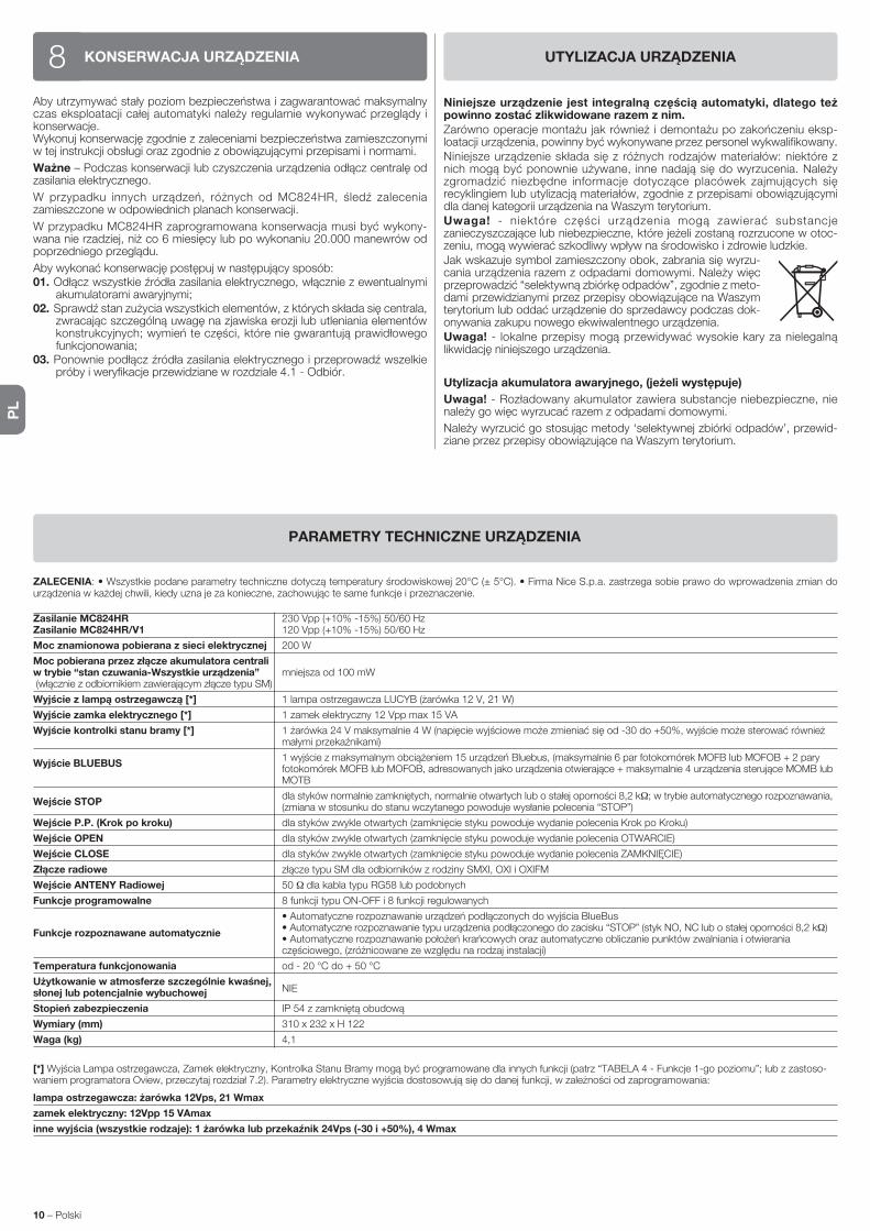
PL
10 – Polski
ZALECENIA: • Wszystkie podane parametry techniczne dotyczą temperatury środowiskowej 20°C (± 5°C). • Firma Nice S.p.a. zastrzega sobie prawo do wprowadzenia zmian do urządzenia w każdej chwili, kiedy uzna je za konieczne, zachowując te same funkcje i przeznaczenie.
Zasilanie MC824HR 230 Vpp (+10% -15%) 50/60 Hz Zasilanie MC824HR/V1 120 Vpp (+10% -15%) 50/60 Hz
Moc znamionowa pobierana z sieci elektrycznej 200 W
Moc pobierana przez złącze akumulatora centrali w trybie “stan czuwania-Wszystkie urządzenia” mniejsza od 100 mW (włącznie z odbiornikiem zawierającym złącze typu SM)
Wyjście z lampą ostrzegawczą [*] 1 lampa ostrzegawcza LUCYB (żarówka 12 V, 21 W)
Wyjście zamka elektrycznego [*] 1 zamek elektryczny 12 Vpp max 15 VA
Wyjście kontrolki stanu bramy [*] 1 żarówka 24 V maksymalnie 4 W (napięcie wyjściowe może zmieniać się od -30 do +50%, wyjście może sterować również małymi przekaźnikami)
Wyjście BLUEBUS 1 wyjście z maksymalnym obciążeniem 15 urządzeń Bluebus, (maksymalnie 6 par fotokomórek MOFB lub MOFOB + 2 pary
fotokomórek MOFB lub MOFOB, adresowanych jako urządzenia otwierające + maksymalnie 4 urządzenia sterujące MOMB lub MOTB
Wejście STOP dla styków normalnie zamkniętych, normalnie otwartych lub o stałej oporności 8,2 kΩ; w trybie automatycznego rozpoznawania,
(zmiana w stosunku do stanu wczytanego powoduje wysłanie polecenia “STOP”)
Wejście P.P. (Krok po kroku) dla styków zwykle otwartych (zamknięcie styku powoduje wydanie polecenia Krok po Kroku)
Wejście OPEN dla styków zwykle otwartych (zamknięcie styku powoduje wydanie polecenia OTWARCIE)
Wejście CLOSE dla styków zwykle otwartych (zamknięcie styku powoduje wydanie polecenia ZAMKNIĘCIE)
Złącze radiowe złącze typu SM dla odbiorników z rodziny SMXI, OXI i OXIFM
Wejście ANTENY Radiowej 50 Ω dla kabla typu RG58 lub podobnych
Funkcje programowalne 8 funkcji typu ON-OFF i 8 funkcji regulowanych
• Automatyczne rozpoznawanie urządzeń podłączonych do wyjścia BlueBus
Funkcje rozpoznawane automatycznie • Automatyczne rozpoznawanie typu urządzenia podłączonego do zacisku “STOP” (styk NO, NC lub o stałej oporności 8,2 kΩ)
• Automatyczne rozpoznawanie położeń krańcowych oraz automatyczne obliczanie punktów zwalniania i otwierania częściowego, (zróżnicowane ze względu na rodzaj instalacji)
Temperatura funkcjonowania od - 20 °C do + 50 °C
Użytkowanie w atmosferze szczególnie kwaśnej, NIE
słonej lub potencjalnie wybuchowej
Stopień zabezpieczenia IP 54 z zamkniętą obudową
Wymiary (mm) 310 x 232 x H 122
Waga (kg) 4,1
[*] Wyjścia Lampa ostrzegawcza, Zamek elektryczny, Kontrolka Stanu Bramy mogą być programowane dla innych funkcji (patrz “TABELA 4 - Funkcje 1-go poziomu”; lub z zastoso-waniem programatora Oview, przeczytaj rozdział 7.2). Parametry elektryczne wyjścia dostosowują się do danej funkcji, w zależności od zaprogramowania:
lampa ostrzegawcza: żarówka 12Vps, 21 Wmax
zamek elektryczny: 12Vpp 15 VAmax
inne wyjścia (wszystkie rodzaje): 1 żarówka lub przekaźnik 24Vps (-30 i +50%), 4 Wmax
PARAMETRY TECHNICZNE URZĄDZENIA
KONSERWACJA URZĄDZENIA8Aby utrzymywać stały poziom bezpieczeństwa i zagwarantować maksymalny czas eksploatacji całej automatyki należy regularnie wykonywać przeglądy i konserwacje.Wykonuj konserwację zgodnie z zaleceniami bezpieczeństwa zamieszczonymi w tej instrukcji obsługi oraz zgodnie z obowiązującymi przepisami i normami.
Ważne – Podczas konserwacji lub czyszczenia urządzenia odłącz centralę od zasilania elektrycznego.
W przypadku innych urządzeń, różnych od MC824HR, śledź zalecenia zamieszczone w odpowiednich planach konserwacji.
W przypadku MC824HR zaprogramowana konserwacja musi być wykony-wana nie rzadziej, niż co 6 miesięcy lub po wykonaniu 20.000 manewrów od po przedniego przeglądu.
Aby wykonać konserwację postępuj w następujący sposób: 01. Odłącz wszystkie źródła zasilania elektrycznego, włącznie z ewentualnymi
akumulatorami awaryjnymi; 02. Sprawdź stan zużycia wszystkich elementów, z których składa się centrala,
zwracając szczególną uwagę na zjawiska erozji lub utleniania elementów konstrukcyjnych; wymień te części, które nie gwarantują prawidłowego funkcjonowania;
03. Ponownie podłącz źródła zasilania elektrycznego i przeprowadź wszelkie próby i weryfikacje przewidziane w rozdziale 4.1 - Odbiór.
UTYLIZACJA URZĄDZENIA
Niniejsze urządzenie jest integralną częścią automatyki, dlatego też powinno zostać zlikwidowane razem z nim.Zarówno operacje montażu jak również i demontażu po zakończeniu eksp-loatacji urządzenia, powinny być wykonywane przez personel wykwalifikowany.Niniejsze urządzenie składa się z różnych rodzajów materiałów: niektóre z nich mogą być ponownie używane, inne nadają się do wyrzucenia. Należy zgromadzić niezbędne informacje dotyczące placówek zajmujących się recyklingiem lub utylizacją materiałów, zgodnie z przepisami obowiązującymi dla danej kategorii urządzenia na Waszym terytorium.Uwaga! - niektóre części urządzenia mogą zawierać substancje zanieczyszczające lub niebezpieczne, które jeżeli zostaną rozrzucone w otoc-zeniu, mogą wywierać szkodliwy wpływ na środowisko i zdrowie ludzkie.Jak wskazuje symbol zamieszczony obok, zabrania się wyrzu-cania urządzenia razem z odpadami domowymi. Należy więc przeprowadzić “selektywną zbiórkę odpadów”, zgodnie z me to-dami przewidzianymi przez przepisy obowiązujące na Wa szym terytorium lub oddać urządzenie do sprzedawcy podczas dok-onywania zakupu nowego ekwiwalentnego urządzenia.Uwaga! - lokalne przepisy mogą przewidywać wysokie kary za nielegalną likwidację niniejszego urządzenia.
Utylizacja akumulatora awaryjnego, (jeżeli występuje)
Uwaga! - Rozładowany akumulator zawiera substancje niebezpieczne, nie należy go więc wyrzucać razem z odpadami domowymi.
Należy wyrzucić go stosując metody ‘selektywnej zbiórki odpadów’, przewid-ziane przez przepisy obowiązujące na Waszym terytorium.

NL
Nederlands – 1
NEDERLANDS
InhoudsopgaveALGEMENE AANBEVELINGEN EN VOORZORGSMAATREGELEN . . . . 1Aanbevelingen voor de veiligheid . . . . . . . . . . . . . . . . . . . . . . . . . . . . . . . . . 1Aanbevelingen voor de installatie . . . . . . . . . . . . . . . . . . . . . . . . . . . . . . . . . 1Aanbevelingen voor het gebruik . . . . . . . . . . . . . . . . . . . . . . . . . . . . . . . . . . 1
1 - BESCHRIJVING VAN HET PRODUCT EN GEBRUIKSBESTEMMING. . 1
2 - INSTALLATIE . . . . . . . . . . . . . . . . . . . . . . . . . . . . . . . . . . . . . . . . . . . . 12.1 - Controles voorafgaand aan de installatie . . . . . . . . . . . . . . . . . . . . . . . 12.2 - Gebruikslimieten van het product . . . . . . . . . . . . . . . . . . . . . . . . . . . . . 22.3 - Typische installatie . . . . . . . . . . . . . . . . . . . . . . . . . . . . . . . . . . . . . . . . 22.4 - Installatie van de besturingseenheid . . . . . . . . . . . . . . . . . . . . . . . . . . . 2
3 - ELEKTRISCHE AANSLUITINGEN . . . . . . . . . . . . . . . . . . . . . . . . . . . . 23.1 - Beschrijving van de elektrische aansluitingen . . . . . . . . . . . . . . . . . . . . 23.2 - Elektrische aansluitingen van de besturingseenheid MC824HR . . . . . . 33.3 - Aansluiting op de MC824HR van andere inrichtingen . . . . . . . . . . . . . . 33.4 - Adressering van de met de MC824HR verbonden inrichtingen . . . . . . . 33.5 - Eerste inschakeling en controle van de aansluitingen . . . . . . . . . . . . . . 33.6 - Zelflering van de met de MC824HR verbonden inrichtingen . . . . . . . . . 33.7 - Zelflering van de posities van de mechanische eindaanslagen . . . . . . . 3 3.7.1 - Zelflering in automatische modus . . . . . . . . . . . . . . . . . . . . . . . 4 3.7.2 - Zelflering in handmatige modus . . . . . . . . . . . . . . . . . . . . . . . . . 4 3.7.3 - Zelflering in gemengde modus . . . . . . . . . . . . . . . . . . . . . . . . . 43.8 - Controle van de beweging van de vleugels van de poort . . . . . . . . . . . 4
4 - EINDTEST EN INBEDRIJFSTELLING . . . . . . . . . . . . . . . . . . . . . . . . . 44.1 - Eindtest . . . . . . . . . . . . . . . . . . . . . . . . . . . . . . . . . . . . . . . . . . . . . . . . 54.2 - Inbedrijfstelling . . . . . . . . . . . . . . . . . . . . . . . . . . . . . . . . . . . . . . . . . . . 5
5 - PROGRAMMERING . . . . . . . . . . . . . . . . . . . . . . . . . . . . . . . . . . . . . . . 55.1 - Programmering eerste niveau (ON-OFF) . . . . . . . . . . . . . . . . . . . . . . . . 55.2 - Programmering tweede niveau (instelbare parameters) . . . . . . . . . . . . . 65.3 - Speciale functies . . . . . . . . . . . . . . . . . . . . . . . . . . . . . . . . . . . . . . . . . 75.4 - Wissen van het geheugen . . . . . . . . . . . . . . . . . . . . . . . . . . . . . . . . . . 8
6 - WAT TE DOEN ALS...(handleiding voor het oplossen van proble-men) . . . . . . . . . . . . . . . . . . . . . . . . . . . . . . . . . . . . . . . . . . . . . . . . . . . . . . 8
7 - VERDERE DETAILS . . . . . . . . . . . . . . . . . . . . . . . . . . . . . . . . . . . . . . . 97.1 - Aansluiting van een radio-ontvanger . . . . . . . . . . . . . . . . . . . . . . . . . . . 97.2 - Aansluiting van de Oview programmeereenheid . . . . . . . . . . . . . . . . . . 97.3 - Aansluiting van het zonne-energiesysteem Solemyo . . . . . . . . . . . . . . . 97.4 - Aansluiting van de bufferbatterij mod. PS324 . . . . . . . . . . . . . . . . . . . . 9
8 - ONDERHOUD VAN HET PRODUCT . . . . . . . . . . . . . . . . . . . . . . . . . 10
AFDANKEN VAN HET PRODUCT . . . . . . . . . . . . . . . . . . . . . . . . . . . . . . 10
TECHNISCHE GEGEVENS VAN HET PRODUCT . . . . . . . . . . . . . . . . . . 10
EG-VERKLARING VAN OVEREENSTEMMING . . . . . . . . . . . . . . . . . . . . IV
Instructies en aanbevelingen voor de gebruiker . . . . . . . . . . . . . . . . . . XIAfbeeldingen . . . . . . . . . . . . . . . . . . . . . . . . . . . . . . . . . . . . . . . . . . . . . . XII
MC824HR is een elektronische besturingseenheid voor de automatisering van hekken met dichtzwaaiende vleugels en een motor uit de Toona-serie van het model 5624I (zie paragraaf 2.2, “Gebruikslimieten van het product”). LET OP! – Ieder gebruik dat afwijkt van hetgeen hier beschreven is en in ande-re omgevingscondities dan in deze handleiding zijn vermeld dient als oneigenlijk en dus als verboden te worden beschouwd!De besturingseenheid is met name geschikt voor aansluiting op inrichtingen die tot het systeem Opera, het systeem Bluebus en het systeem voor voeding op zonne-energie Solemyo behoren.Als de besturingseenheid op netvoeding werkt, kan hij worden uitgerust met een bufferbatterij (mod. PS324, optioneel accessoire) die er bij een stroomuitval (black-out) garant voor staat dat de automatisering in de op de stroomuitval volgende uren nog enkele manoeuvres kan uitvoeren.Andere leverbare accessoires zijn de ontvangers die zijn voorzien van de aan-sluiting “SM” (SMXI, OXI, etc.).
BESCHRIJVING VAN HET PRODUCT EN GEBRUIKSBESTEMMING1
Aanbevelingen voor de veiligheid• LET OP! – Deze handleiding bevat belangrijke aanwijzingen voor de
veiligheid van de betrokken personen. Een onjuiste installatie kan ernstig letsel veroorzaken. Alvorens met de werkzaamheden te beginnen dient u de handleiding volledig door te lezen. In geval van twijfel, het product niet instal-leren en opheldering vragen aan de klantenservice van Nice.
• LET OP! – Belangrijke aanwijzingen: bewaar deze handleiding voor eventuele toekomstige onderhoudswerkzaamheden of de verwerking als afval van het afgedankte product.
• LET OP! – Volgens de meest recente Europese wetgeving moet een automatische deur of hek de voorschriften van de richtlijn 2006/42/EG (ex 98/37/EG) (Machinerichtlijn) in acht nemen en in het bijzonder de voorschriften EN 12445; EN 12453; EN 12635 en EN 13241-1, waarmee de conformiteit van de automatisering kan worden verklaard. Met het oog hierop mogen alle werkzaamheden betreffende de installatie, de aansluiting, het testen en het onderhoud van het product uitsluitend door een erkende vakman worden verricht!
Aanbevelingen voor de installatie• Voordat u met de installatie begint, dient u te controleren of dit product
ge schikt is voor het beoogde gebruik (zie de “Gebruikslimieten” paragraaf 2.2 en de “Technische gegevens van het product”). Als het product niet geschikt is, dient u het NIET te installeren.
• De inhoud van deze handleiding heeft betrekking op een typische installatie zoals beschreven in afb. 2a.
• Alle installatie- en onderhoudswerkzaamheden moeten worden ver-richt bij van het elektriciteitsnet gekoppelde automatisering. Als de ontkoppelinrichting van de voeding niet zichtbaar is vanaf de plaats waar het automatische systeem is geplaatst, moet er voordat met het werk begon-nen wordt een bord op de ontkoppelinrichting worden bevestigd met het opschrift “LET OP! ONDERHOUD IN UITVOERING”.
• In het voedingsnet van de installatie dient een afkoppelingsinrichting te wor-den geïnstalleerd met een openingsafstand tussen de contacten die een vol-ledige afkoppeling toelaat in de condities die worden voorgeschreven door de overspanningcategorie III.
• De besturingseenheid moet worden aangesloten op een elektrische voe-dingsleiding die correct geaard is.
• Behandel het product gedurende de installatie voorzichtig en voorkom sa mendrukking, stoten, valpartijen of contact met vloeistoffen van welke soort dan ook. Plaats het product niet in de buurt van warmtebronnen en stel hem niet bloot aan open vuur. Een dergelijke handelswijze kan het pro-duct beschadigen en storingen of gevaarlijke situaties veroorzaken. Als dit ge beurt, de installatie onmiddellijk onderbreken en contact opnemen met de klantenservice van Nice.
• Voer geen wijzigingen uit op onderdelen van het product. Niet-toegestane handelingen zullen slechts storingen in de werking veroorzaken. De fabrikant aanvaardt geen aansprakelijkheid voor schade die het gevolg is van op wil-lekeurige wijze gewijzigde inrichtingen.
• De afvalverwerking van het verpakkingsmateriaal van het product moet vol-gens de plaatselijk geldende regels plaatsvinden.
Aanbevelingen voor het gebruik• Het product is niet bestemd om gebruikt te worden door personen (inclusief
kinderen) wier fysieke, zintuiglijke of mentale vermogens beperkt zijn of die niet over genoeg ervaring of kennis beschikken, tenzij deze personen onder toezicht staan van een persoon die voor hun veiligheid verantwoordelijk is of instructies hebben ontvangen over het gebruik van het product.
• Kinderen die zich in de nabijheid van de automatisering bevinden, dienen in het oog te worden gehouden om er zeker van te zijn dat ze er niet mee spelen.
• Laat kinderen niet met vaste bedieningsinrichtingen spelen. Houd draagbare bedieningen (afstandsbedieningen) buiten het bereik van kinderen.
ALGEMENE AANBEVELINGEN EN VOORZORGSMAATREGELEN
2.1 - Controles voorafgaand aan de installatie
Voordat u gaat installeren dient u te controleren of de onderdelen van het product intact zijn, het gekozen model adequaat is en de omgeving van installatie geschikt:
INSTALLATIE2

NL
2 – Nederlands
ELEKTRISCHE AANSLUITINGEN3
De elektrische aansluiting van de verschillende inrichtingen (fotocellen, digitale toet-senborden, lezers voor transpondercards etc.) van de automatisering op de bestu-ringseenheid moet tot stand worden gebracht via het “Bluebus” systeem van Nice.
3.1 - Beschrijving van de elektrische aansluitingen (afb. 6)
ANTENNE ingang voor de antenne van een radio-ontvanger
FLASH uitgang voor 1 knipperlicht met lampje van 12 V (maximaal 21 W). [*]
ELS uitgang voor elektrisch slot van 12 Vac (maximaal 15 VA). [*]
S.C.A. “Lampje Poort Open”: uitgang voor 1 signaleringslampje van 24 V en maximaal 4 W. [*]
BLUEBUS ingang voor compatibele inrichtingen (MOFB, MOFOB, MOB en MOTB; parallelle aansluiting van de inrichtingen door middel van 2 draden die zowel voor de stroomtoevoer als voor de communi-catiesignalen dienen, er hoeft geen bepaalde polariteit te worden aangehouden. De elektrische aansluiting moet van het parallelle type zijn en het is niet nodig om een bepaalde polariteit aan te hou-den. Gedurende de zelfleringfase zal elke op de besturingseenheid verbonden inrichting dankzij zijn eenduidige code apart door de besturingseenheid worden herkend. Iedere keer dat er een inrichting wordt verwijderd of toegevoegd, moet de deze inrichting eerst door de besturingseenheid worden ‘herkend’ (zelflering, paragraaf 3.6).
STOP ingang voor inrichtingen die met hun interventie een onmiddellijke onderbreking van de aan de gang zijnde manoeuvre gevolgd door een korte omkering, veroorzaken; mogelijkheid tot het aansluiten van con-tacten van het type NO (normaal open), NC (normaal gesloten) of van inrichtingen met uitgang met constante weerstand 8,2 kΩ (contactlijs-ten). Iedere met deze ingang verbonden inrichting wordt gedurende de zelfleringfase apart door de besturingseenheid ‘herkend’ (paragraaf
3.4); in deze fase veroorzaakt hij, als de besturingseenheid een wil-lekeurige afwijking ten opzichte van de geleerde status detecteert, een STOP. Het is mogelijk op deze ingang één of meer, ook onderling van elkaar verschillende inrichtingen aan te sluiten:
– parallelle aansluiting van meerdere NO inrichtingen, zonder beperkingen van het aantal;
– sluit meerdere in serie geschakelde NC inrichtingen aan, zonder beperking van aantal;
– parallelle aansluiting van 2 inrichtingen met uitgang met con-stante weerstand 8,2 kΩ. Als er meer dan 2 inrichtingen zijn, dienen deze in cascade te worden aangesloten, met slechts 1 afsluitweerstand van 8,2 kΩ;
– sluit 2 inrichtingen NO en NC parallel aan, en sluit een weerstand van 8,2 kΩ in serie aan met het contact NC (dit maakt ook de combinatie tussen 3 inrichtingen NO - NC en 8,2 kΩ mogelijk)
P.P. ingang voor bedieningsinrichtingen die bij activering de manoeuvre in modus Stap-voor-stap aansturen; mogelijkheid tot aansluiting van contacten van het type NO
OPEN ingang voor bedieningsinrichtingen die bij activering alleen de ope-ningsmanoeuvre aansturen; mogelijkheid tot aansluiting van con-tacten van het type NO
CLOSE ingang voor bedieningsinrichtingen die bij activering alleen de sluit-manoeuvre aansturen; mogelijkheid tot aansluiting van contacten van het type NO
ENC1 ingang encoder - reductiemotor 1 (klem 1, 2); er hoeft geen bepaalde polariteit te worden aangehouden
ENC2 ingang encoder - reductiemotor 2 (klem 4, 5); er hoeft geen bepaalde polariteit te worden aangehouden
M1 uitgang voor reductiemotor 1 (klem 7, 8, 9)
M2 uitgang voor reductiemotor 2 (klem 10, 11, 12)
[*] De uitgangen FLASH, ELS en S.C.A. kunnen met andere functies gepro-grammeerd worden (zie “TABEL 4 - Functies 1° niveau; of via Oview program-meereenheid, zie hoofdstuk 7.2).
• Vergewis u ervan dat al het te gebruiken materiaal in optimale staat is en geschikt is voor het voorziene gebruik.
• Controleer of alle gebruikscondities stroken met de gebruikslimieten van het product (paragraaf 2.2) en met de waardelimieten die vermeld zijn in de “Technische gegevens van het product”.
• Controleer of de voor de installatie gekozen ruimte compatibel is met de totaalafmetingen van het product (zie afb. 1).
• Controleer of het voor de installatie van het product gekozen vlak van stevig materiaal is en een stabiele bevestiging kan verzekeren.
• Controleer of er op de plaats van bevestiging geen kans op wateroverlast bestaat; monteer het product eventueel hoog genoeg boven de grond.
• Controleer of er genoeg ruimte rond het product is om er makkelijk en veilig bij te kunnen.
• Controleer of alle gebruikte elektriciteitskabels van het in Tabel 1 vermelde type zijn.
• Controleer of de mechanische stops voor zowel de sluitbeweging als de ope-ningsbeweging van de automatisering aanwezig zijn.
2.2 - Gebruikslimieten van het product
De besturingseenheid MC824HR kan alleen worden gebruikt met de Toona-reductiemotor van mod. 5624I; deze motoren zijn omkeerbaar: dat wil zeggen dat de vleugels van het hek handmatig bewogen kunnen worden zonder dat de reductiemotor handmatig gedeblokkeerd hoeft te worden. Dankzij een sensor in de motor is de besturingseenheid in staat de handmatige beweging van de vleu-gels te detecteren en bovendien de daarop volgende manoeuvres op de juiste wijze te reguleren; zo wordt voorkomen dat de vleugels tegen de mechanische eindstops bij opening of sluiting botsen. Let op! - Als de besturingseenheid niet correct op voeding is aangesloten of als de functie “Alles stand-by” actief is, wordt de handmatige beweging van de vleugels niet gedetecteerd.
2.3 - Typische installatie
Op afb. 2a wordt een voorbeeld getoond van een automatiseringsinstallatie die gerealiseerd is met onderdelen van Nice:a - Besturingseenheid
b - Reductiemotorc - Knipperlichtd - Fotocele - Digitaal toetsenbord - Transponder-lezer - Sleutelschakelaarf - Zuil voor fotocelg - Mechanische stops openingsbewegingh - Mechanische stop sluitbewegingi - Elektrisch slot
Deze onderdelen zijn geplaatst volgens een gebruikelijk standaardschema. Gebruik de afb. 2a om bij benadering de plaats van installatie van elk onder-deel van het systeem te bepalen. Belangrijk – Prepareer, voordat u het pro-duct gaat installeren, de elektriciteitskabels die nodig zijn voor de installatie, zie afb. 2b en “Tabel 1 - Technische gegevens van de elektriciteitskabels”.Let op – Gedurende het plaatsen van de buizen voor het doorvoeren van de elektriciteitskabels en de invoer van de kabels in de kast van de besturingseen-heid, dient u er rekening mee te houden dat als gevolg van water dat zich ver-zamelt in de putjes, in de verbindingsleidingen condens kan ontstaan die in het binnenste van de besturingseenheid terecht kan komen en daar schade aan de elektronische circuits kan veroorzaken
2.4 - Installatie van de besturingseenheid
Ga voor de bevestiging van de besturingseenheid te werk zoals te zien is op afb. 3:01. Open de kast van de besturingseenheid door de schroeven (afb. 3-A) los
te draaien;02. Maak de gaten voor het doorvoeren van de elektriciteitskabels (afb. 3-B);03. Bevestig de kast (afb. 3-C);04. Op dit punt kunt u de elektrische aansluitingen tot stand brengen, zie
hoofdstuk 3.Let op! – Voor de installatie van de buizen voor de elektriciteitskabels, dient u een gat te boren in de onderkant van de kast van de besturingseenheid. Opmerking – Indien nodig kan de kabelingang aan de zijkant gebruikt worden, maar alleen als er geschikte verbindingsstukken voor buizen worden gebruikt.Zie voor de installatie van de overige inrichtingen van de automatisering de betreffende instructiehandleidingen.
C Aansluiting Type kabel Maximaal toegestane lengte
A: Kabel voor STROOMTOEVOER BESTURINGSEENHEID 1 kabel 3 x 1,5 mm2 30 m (opmerking 1)
B: Kabel KNIPPERLICHT met antenne 1 kabel 2 x 0,5 mm2 20 m 1 afgeschermde kabel type RG58 20 m (aanbevolen: minder dan 5 m)
C: Kabel BLUEBUS INRICHTINGEN 1 kabel 2 x 0,5 mm2 20 m (opmerking 2)
D: Kabel SLEUTELSCHAKELAAR 2 kabels 2 x 0,5 mm2 (opmerking 3) 50 m
E: Kabel voor STROOMTOEVOER REDUCTIEMOTOR 1 kabel 3 x 1,5 mm2 (opmerking 4) 10 m
F: Kabel voor AANSLUITING ENCODER 1 kabel 2 x 1 mm2 (opmerking 4) 10 m
G: Kabel voor AANSLUITING ELEKTRISCH SLOT 1 cavo 2 x 1 mm2 10 m
Opmerking 1 – Als de voedingskabel langer dan 30 m is, dient een kabel met grotere doorsnede te worden gebruikt (3 x 2,5 mm2) en is het noodzakelijk in de nabijheid van de automatisering een veiligheidsaarding aan te brengen.Opmerking 2 – Als de Bluebus kabel langer dan 20 m is, tot een lengte van maximaal 40 m, dient een kabel met een grotere doorsnede te worden gebruikt (2 x 1 mm2).Opmerking 3 – Deze 2 kabels kunnen vervangen worden door 1 enkele kabel van 4 x 0,5 mm2.Opmerking 4 – Deze kabels kunnen vervangen worden door 1 enkele kabel van 5 x 1,5 mm2.
LET OP! – De gebruikte kabels moeten geschikt zijn voor het type omgeving waar de automatisering geïnstalleerd wordt.
TABEL 1 - Technische gegevens van de elektriciteitskabels (afb. 2b)

NL
Nederlands – 3
3.5 - Eerste inschakeling en controle van de aansluitingen
Na de besturingseenheid onder spanning te hebben gezet, dient u de volgende controles uit te voeren:• na enkele seconden, controleren of de led “Bluebus” (afb. 7) regelmatig knip-
pert, met een frequentie van 1 maal per seconde;• controleer of de led’s van de fotocellen (afb. 7), zowel TX als RX, knipperen.
De manier waarop de led’s knipperen is in deze fase niet van belang;• controleer of het knipperlicht dat is aangesloten op de uitgang FLASH uit is.
Als dit allemaal niet gebeurt, dient de stroomtoevoer naar de besturingseenheid te worden uitgeschakeld en dient u de verschillende, eerder tot stand gebrach-te, elektrische aansluitingen te controleren.
3.6 - Zelflering van de met de MC824HR verbonden inrichtingen
Na de eerste inschakeling dient u de besturingseenheid de procedure voor her-kenning van de met de ingangen “Bluebus” en “Stop” verbonden inrichtingen uit te voeren.
LET OP! – De zelfleringfase moet ook worden uitgevoerd als er geen enkele inrichting met de besturingseenheid is verbonden.
Dankzij de zelfleringprocedure is de besturingseenheid in staat de verschillende aangesloten inrichtingen apart te herkennen en de mogelijke aanwezige storin-gen te detecteren. Om deze reden dient de zelfleringprocedure iedere keer dat er een inrichting wordt toegevoegd of verwijderd te worden uitgevoerd.De led’s “L1” en “L2” op de besturingseenheid (afb. 7) zullen langzaam knip-peren, om aan te geven dat de zelfleringprocedure moet worden uitgevoerd:
01. Druk de toetsen “ ” en “Set” (afb. 7) tegelijkertijd in en houd ze ingedrukt.02. Laat de toetsen los wanneer de led’s “L1” en “L2” snel beginnen te knip-
peren (na circa 3 seconden).03. Wacht enkele seconden tot de besturingseenheid de fase voor zelflering
van de inrichtingen voltooid heeft.04. Na afloop van deze fase moet de led “Stop” branden en moeten de led’s
“L1” en “L2” uitgaan (het is mogelijk dat de led’s “L3” en “L4” beginnen te knipperen).
3.7 - Zelflering van de posities van de mechanische eindaansla-gen
Na de zelflering van de aangesloten inrichtingen (paragraaf 3.6), dienen de posities van de mechanische stops (maximale openingsstand en maximale sluitingsstand) te worden aangeleerd. Deze procedure kan in drie modi worden uitgevoerd: automatisch, handmatig en gemengd.In de automatische modus, voert de besturingseenheid de procedure voor zelf-lering van de mechanische stops uit en berekent wat de beste faseverschillen van de vleugels zijn (SA en SC, afb. B).In de handmatige modus worden de acht posities van de mechanische stops (afb. B) één voor één geprogrammeerd door de vleugels op de gewenste pun-ten te zetten. De te programmeren positie kan gevonden worden aan de hand van het knipperen van één de 8 led’s (L1...L8), zie Tabel 3.In de gemengde modus is het mogelijke de automatische procedure uit te voe-ren en vervolgens met de handmatige procedure één of meer posities te wijzi-gen, met uitzondering van de posities “0” en “1” (afb. B) die gelijk zijn aan de posities van de mechanische stops.
3.2 - Elektrische aansluitingen van de besturingseenheid MC824HR
Na de kast van de besturingseenheid te hebben bevestigd en de gaten voor het doorvoeren van de elektriciteitskabels te hebben geboord (hoofdstuk 2.4 en afb. 3), de elektrische aansluitingen tot stand brengen:
LET OP!– Bij het uitvoeren van elektrische aansluitingen mag de installatie absoluut niet op de netspanning zijn aangesloten en moet de bufferbat-terij van de automatisering, indien aanwezig, zijn afgekoppeld.– De aansluitwerkzaamheden mogen uitsluitend door gekwalificeerd personeel worden uitgevoerd.– Op de elektrische voedingsleiding dient een inrichting te worden aangebracht dat volledige afkoppeling van de automatisering van het elektriciteitsnet verze-kert. Deze afkoppelinrichting moet een dusdanige openingsafstand tussen de contacten hebben dat complete afkoppeling wordt verzekerd in de condities die worden voorgeschreven door de overspanningcategorie III, in overeen-stemming met de installatievoorschriften. Indien nodig garandeert deze inrich-ting een snelle en veilige afkoppeling van de voeding; de inrichting moet dan ook in het zicht van de automatisering worden geïnstalleerd. Als de inrichting op een niet-zichtbare plaats zit, moet hij een systeem hebben dat een even-tuele ongewilde of niet-geautoriseerde heraansluiting van de voeding tegen-houdt, om iedere kans op gevaarlijke situaties uit te sluiten. De afkoppelinrich-ting wordt niet bij het product geleverd.
01. Sluit eerst de elektrische voedingskabel aan (afb. 4) en blokkeer hem met de kabelklem;
02. Sluit nu de elektriciteitskabels van de motoren M1 en M2 aan, en volg hierbij de symbolen op het etiket (afb. 5):
a) sluit op de klem M1 de motor aan die de onderste vleugel aandrijft (de tweede die de openingsmanoeuvre begint ) en vervolgens de bijbehorende encoder op de klemmen 1-2;
b) sluit op de klem M2 de motor aan die de bovenste vleugel aandrijft (de eerste die de openingsmanoeuvre begint) en vervolgens de bijbehorende encoder op de klemmen 4-5
BELANGRIJK! – Indien er slechts één reductiemotor in de installatie aanwezig is, sluit u deze aan op de klem M2 en laat u de klem M1 vrij;
03. Sluit nu de elektriciteitskabels van de verschillende inrichtingen aan, zie hier-voor afb. 6 en paragraaf 3.3. Opmerking – Om het aansluiten van de kabels te vergemakkelijken, is het mogelijk de klemmen uit hun behuizingen te halen.
3.3 - Aansluiting op de MC824HR van andere inrichtingen
Als er nog andere inrichtingen in de installatie van stroom moet voorzien, bij-voorbeeld een lezer voor transpondercards of het lampje voor de verlichting van de sleutelschakelaar, is het mogelijk deze inrichtingen aan te sluiten op de besturingseenheid, op de klemmen “P.P. (positief)” en “STOP (negatief)” (afb. 6). De voedingsspanning is 24 Vcc (-30% ÷ +50%) met een maximaal beschik-bare stroom van 200 mA.Opmerking – De spanning die beschikbaar is op de klemmen “P.P.” en “STOP”, blijft ook aanwezig wanneer de functie “Stand By” op de kaart geac-tiveerd wordt.
3.4 - Adressering van de met de MC824HR verbonden inrichtin-gen
Om de besturingseenheid in staat te stellen om de op het Bluebus systeem aangesloten inrichtingen te herkennen, dient u een adres aan deze inrichtingen te geven.. Hiervoor dient de elektrische geleidebrug die in elke inrichting aan-wezig is in de correcte positie te worden gebracht, zie de instructiehandleiding van de verschillende inrichtingen: zie afb. A en Tabel 2.Na afloop van de installatieprocedure of na het verwijderen van fotocellen of andere inrichtingen, dient de zelfleringprocedure voor deze inrichtingen te wor-den uitgevoerd, zie de paragraaf 3.6.
A
TABEL 2 - ADRESSEN VAN DE FOTOCELLEN
Fotocel Bruggen
FOTO Externe fotocel h = 50 met activering in sluitbeweging (onderbreking en omkering van de beweging)
FOTO II Externe fotocel h = 100 met activering in sluitbeweging (onderbreking en omkering van de beweging)
FOTO 1 Interne fotocel h = 50 met activering zowel in sluitbeweging (onderbreking en omkering van de beweging) als in openingsbeweging (onderbreking en hervatting van de beweging op het moment dat de fotocel weer vrij wordt gegeven)
FOTO 1 II Interne fotocel h = 100 met activering zowel in sluitbeweging (onderbreking en omkering van de beweging) als in openingsbeweging (onderbreking en hervatting van de beweging op het moment dat de fotocel weer vrij wordt gegeven)
FOTO 2 Interne fotocel met activering in openingsbeweging (onderbreking en omkering van de beweging)
FOTO 2 II Interne fotocel met activering in openingsbeweging (onderbreking en omkering van de beweging)
FOTO 3 CONFIGURATIE NIET TOEGESTAAN
0
1 1A
SC
SA
A
0M1 M2
B POSITIES
TABEL 3
Positie Led Beschrijving
Positie 0(motor 1)
Positie 0(motor 2)
Positie SA(motor 2)
Positie voor maximale sluiting: wanneer de vleugel 1 de me chanische stop voor de sluitbeweging raakt
Positie voor maximale sluiting: wanneer de vleugel 2 de me chanische stop voor de sluitbeweging raakt
Faseverschil in openingsbeweging: wanneer de vleugel 2 deze positie overschrijdt, begint de opening van de vleugel 1
L1
L2
L3
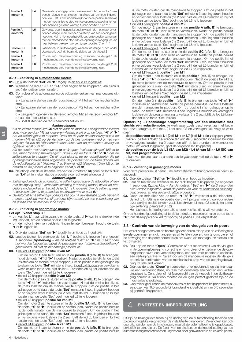
NL
4 – Nederlands
3.7.1 - Zelflering in automatische modus01. Druk de toetsen “Set” en “ ” tegelijk in en houd ze ingedrukt;02. Wanneer de led’s “L3” en “L4” snel beginnen te knipperen, (na circa 3
sec.) de toetsen weer loslaten;03. Controleer of de automatisering de volgende reeksen van manoeuvres uit-
voert: a - Langzaam sluiten van de reductiemotor M1 tot aan de mechanische
stop b - Langzaam sluiten van de reductiemotor M2 tot aan de mechanische
stop c - Langzaam openen van de reductiemotor M2 en de reductiemotor M1
tot aan de mechanische stop d - Snel sluiten van de reductiemotors M1 en M2
Aanbevelingen:– Als de eerste manoeuvre (a) niet de door de motor M1 aangedreven vleugel
sluit, maar de door M2 aangedreven vleugel, drukt u op de toets “ ” of “ ” om de zelfleringfase te stoppen. Draai op dit punt de aansluitingen van de motoren M1 en M2 op de klemmen op de besturingseenheid om en ver-volgens die van de bijbehorende decoders; start de procedure vervolgens opnieuw vanaf punt 01;
– Als de eerste twee manoeuvres (a en b) geen “sluitbewegingen” blijken te zijn, maar “openingsbewegingen”, drukt u op de toets “ ” of “ ” om de zelfleringfase te stoppen. Op dit punt dient u, op de reductiemotor die de openingsmanoeuvre heeft uitgevoerd, de polariteit van de twee draden van de reductiemotor M1 (klemmen 7 en 9) en van M2 (klemmen 10 en 12) om te draaien en de procedure te beginnen vanaf punt 01;
04. Na afloop van de sluitmanoeuvre van de 2 motoren (d) gaan de led’s “L3” en “L4” uit ten teken dat de procedure correct werd uitgevoerd.
Aanbevelingen:– Indien gedurende de automatische zelfleringprocedure de fotocellen of een
met de ingang “stop” verbonden inrichting in werking treden, wordt de pro-cedure onderbroken en begint de led L1 te knipperen. Om de zelflering weer te activeren, dient u te procedure te hervatten vanaf punt 01;
– De automatische zelfleringprocedure kan ook na de installatie op elk gewenst moment opnieuw worden uitgevoerd; bijvoorbeeld na een verandering van de positie van de mechanische stops.
3.7.2 - Zelflering in handmatige modus:Let op! – Vanaf stap 03:– om van led L1 naar L8 te gaan, dient u de toetst of kort in te drukken (de
led knippert, om de actuele positie aan te geven);– om de motor in één van beide richtingen te laten bewegen houd u de toets
of ingedrukt.
01. Druk de toetsen “Set” en “ ” tegelijk in en houd ze ingedrukt;02. Laat de toetsen los wanneer del led “L1” begint te knipperen (na ongeveer
1 seconde); Opmerking – Als de toetsen “Set” en “ ” na 3 seconden niet worden losgelaten, wordt de procedure voor “automatische zelflering” geactiveerd, en niet de handmatige procedure.
03. • de led L1 knippert: positie 0 van M1 Om de motor 1 aan te sturen en in de positie 0 (afb. B) te brengen:
houd de toets “ ” of “ ” ingedrukt. Nadat de positie bereikt is, de toets loslaten om de manoeuvre te stoppen. Om de positie in het geheugen op te slaan, de toets “Set” minstens 3 sec. ingedrukt houden en vervolgens weer loslaten (na 2 sec. blijft de led L1 branden en bij het loslaten van de toets “Set” begint de led L2 te knipperen).
• de led L2 knippert: positie 0 van M2 Om de motor 2 aan te sturen en in de positie 0 (afb. B) te brengen: de
toets “ ” of “ ” indrukken en vasthouden. Nadat de positie bereikt is, de toets loslaten om de manoeuvre te stoppen. Om de positie in het geheugen op te slaan, de toets “Set” minstens 3 sec. ingedrukt houden en vervolgens weer loslaten (na 2 sec. blijft de led L2 branden en bij het loslaten van de toets “Set” begint de led L3 te knipperen).
• de led L3 knippert: positie SA van M2 Om de motor 2 aan te sturen en in de positie SA (afb. B) te brengen:
de toets “ ” of “ ” indrukken en vasthouden. Nadat de positie bereikt is, de toets loslaten om de manoeuvre te stoppen. Om de positie in het geheugen op te slaan, de toets “Set” minstens 3 sec. ingedrukt houden en vervolgens weer loslaten (na 2 sec. blijft de led L3 branden en bij het loslaten van de toets “Set” begint de led L4 te knipperen).
• de led L4 knippert: positie A van M1 Om de motor 1 aan te sturen en in de positie A (afb. B) te brengen:
de toets “ ” of “ ” indrukken en vasthouden. Nadat de positie bereikt
Dit zijn de belangrijkste fasen bij de aanleg van de automatisering teneinde een zo groot mogelijke veiligheid van de installatie te garanderen. De eindtest kan ook gebruikt worden om de inrichtingen, waaruit de automatisering is opgebo u wd, periodiek te controleren. De fasen van de eindtest en de inbedrijfstelling van de automatisering moeten worden uitgevoerd door gekwalificeerd en ervaren perso-
EINDTEST EN INBEDRIJFSTELLING4
is, de toets loslaten om de manoeuvre te stoppen. Om de positie in het geheugen op te slaan, de toets “Set” minstens 3 sec. ingedrukt houden en vervolgens weer loslaten (na 2 sec. blijft de led L4 branden en bij het loslaten van de toets “Set” begint de led L5 te knipperen).
• de led L5 knippert: positie A van M2 Om de motor 2 aan te sturen en in de positie A (afb. B) te brengen:
de toets “ ” of “ ” indrukken en vasthouden. Nadat de positie bereikt is, de toets loslaten om de manoeuvre te stoppen. Om de positie in het geheugen op te slaan, de toets “Set” minstens 3 sec. ingedrukt houden en vervolgens weer loslaten (na 2 sec. blijft de led L5 branden en bij het loslaten van de toets “Set” begint de led L6 te knipperen).
• de led L6 knippert: positie SC van M1 Om de motor 1 aan te sturen en in de positie SC (afb. B) te brengen:
de toets “ ” of “ ” indrukken en vasthouden. Nadat de positie bereikt is, de toets loslaten om de manoeuvre te stoppen. Om de positie in het geheugen op te slaan, de toets “Set” minstens 3 sec. ingedrukt houden en vervolgens weer loslaten (na 2 sec. blijft de led L6 branden en bij het loslaten van de toets “Set” begint de led L7 te knipperen).
• de led L7 knippert: positie 1 van M1 Om de motor 1 aan te sturen en in de positie 1 (afb. B) te brengen: de
toets “ ” of “ ” indrukken en vasthouden. Nadat de positie bereikt is, de toets loslaten om de manoeuvre te stoppen. Om de positie in het geheugen op te slaan, de toets “Set” minstens 3 sec. ingedrukt houden en vervolgens weer loslaten (na 2 sec. blijft de led L7 branden en bij het loslaten van de toets “Set” begint de led L8 te knipperen).
• de led L8 knippert: positie 1 van M2 Om de motor 2 in de positie 1 (afb. B) te brengen: de toets “ ” of “ ”
indrukken en vasthouden. Nadat de positie bereikt is, de toets loslaten om de manoeuvre te stoppen. Om de positie in het geheugen op te slaan, de toets “Set” minstens 3 sec. ingedrukt houden en vervolgens loslaten om de programmering te verlaten (na 2 sec. blijft de led L8 bran-den tot u de toets “Set” loslaat).
Opmerking – Handmatige programmering van een installatie met slechts één reductiemotor: te werk gaan zoals beschreven aan het begin van deze paragraaf, van stap 01 tot stap 03 en vervolgens als volgt te werk gaan:- de posities voor de leds L1 (0 di M1) en L7 (1 di M1) als volgt program-
meren: de toets “Set” gedurende ten minste 3 seconden ingedrukt houden en vervolgens loslaten (na 2 seconden blijft de led branden en wanneer de toets ‘Set’ wordt losgelaten, gaat de volgende led knipperen).
- de posities voor de leds L3 (SA van M2) - L4 (A van M1) - L6 (SC van M1) niet programmeren
- u kunt van de ene naar de andere positie gaan door kort op de toets of te drukken.
3.7.3 - Zelflering in gemengde modusVoer deze procedure uit nadat u de automatische zelfleringprocedure heeft uit-gevoerd:01. Druk de toetsen “Set” en “ ” tegelijk in en houd ze ingedrukt;02. Laat de toetsen los wanneer del led “L1” begint te knipperen (na ongeveer
1 seconde); Opmerking – Als de toetsen “Set” en “ ” na 3 seconden niet worden losgelaten, wordt de procedure voor “automatische zelflering” geactiveerd, en niet de handmatige procedure.
03. Door kort indrukken van de toets “ ” of “ ” verplaatst u de knipperen-de led (L1…L8) naar de positie die u wilt programmeren; ga voor iedere afzonderlijke positie te werk zoals beschreven bij stap 03 van de handma-tige zelflering (paragraaf 3.7.2).
Herhaal deze handeling voor alle andere posities die u wilt veranderen.Om de handmatige zelflering af te sluiten, drukt u meerdere malen op de toets “ ”, om de knipperende led tot voorbij de positie L8 te verplaatsen.
3.8 - Controle van de beweging van de vleugels van de poort
Het wordt aangeraden om de besturingseenheid na afloop van de zelfleringfase enkele openings- en sluitmanoeuvres uit te laten voeren, om te controleren of de beweging van de poort correct is en om eventuele montage- en afstelfouten te corrigeren.
01. Druk op de toets “Open”. Controleer of het faseverschil van de vleugels in de openingsbeweging correct is en controleer of er gedurende de ope-ningsmanoeuvre een versnellingsfase, een fase met constante snelheid, een vertragingsfase is. Na afloop van de manoeuvre moeten de vleugels op enkele centimeters van de mechanische stop van de openingsbewe-ging tot stilstand komen;
02. Druk op de toets “Close” en controleer of er gedurende de sluitmanoeu-vre een versnellingsfase, en fase met constante snelheid en een vertra-gingsfase is. Controleer of het faseverschil van de vleugels in de sluitbewe-ging cor rect is. Na afloop moeten de vleugels perfect gesloten zijn op de mechanische sluitstop;
03. Controleer gedurende de manoeuvres of het knipperlicht knippert met tus-senpozen van 0,5 seconde bij brandend knipperlicht en van 0,5 seconden bij gedoofd knipperlicht.
Positie A(motor 1)
Positie A(motor 2)
Positie SC(motor 1)
Positie 1(motor 1)
Positie 1(motor 2)
Gewenste openingspositie: positie waarin de met motor 1 ver-bonden vleugel moet stoppen na afloop van een openingsma-noeuvre. Het is niet noodzakelijk dat deze positie samenvalt met de mechanische stop van de openingsbeweging, er kan naar believen gekozen worden tussen positie “0” en “1”
Gewenste openingspositie: positie waarin de met motor 2 ver-bonden vleugel moet stoppen na afloop van een openingsma-noeuvre. Het is niet noodzakelijk dat deze positie samenvalt met de mechanische stop van de openingsbeweging, er kan naar believen gekozen worden tussen positie “0” en “1”
Faseverschil in sluitbeweging: wanneer de vleugel 1 zich on der deze positie bevindt, begint de sluiting van de vleugel 2
Positie voor maximale opening: wanneer de vleugel 1 de me chanische stop voor de openingsbeweging raakt
Positie voor maximale opening: wanneer de vleugel 2 de me chanische stop voor de openingsbeweging raakt
L4
L5
L6
L7
L8
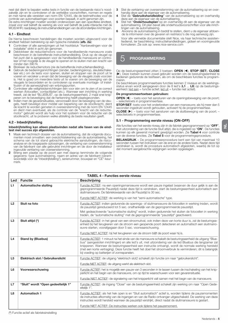
NL
Nederlands – 5
Op de besturingseenheid zitten 3 toetsen: OPEN ( ), STOP (SET), CLOSE ( ). Deze toetsen kunnen zowel gebruikt worden om de besturingseenheid te bedienen gedurende de testfasen, als om de beschikbare functies te program-meren.De beschikbare programmeerbare functies kennen 2 niveaus en de werkings-status ervan wordt aangegeven door de 8 led’s (L1 ... L8) op de besturings-eenheid ( led aan = functie actief; led uit = functie niet actief).
De programmeertoetsen gebruiken:
OPEN ( ): – toets voor het aansturen van de openingsbeweging van de poort; – selectietoets in programmeerfase.STOP/SET: toets voor het onderbreken van een manoeuvre; als hij meer dan 5 seconden ingedrukt wordt gehouden, activeert hij de programmeerfase.CLOSE ( ): – toets voor het aansturen van de sluitbeweging van de poort; – selectietoets in programmeerfase.
5.1 - Programmering eerste niveau (ON-OFF)
Alle functies van het eerste niveau zijn in de fabriek geprogrammeerd op “OFF”, met uitzondering van de functie Sluit altijd, die is ingesteld op “ON”. De functies kunnen op elk gewenst moment gewijzigd worden. Zie Tabel 4 voor controle van de diverse functies. Zie Tabel 5 voor de programmeringsprocedure.
BELANGRIJK – De programmeerprocedure kent een tijd van maximaal 10 seconden tussen het indrukken van de ene en de andere toets. Nadat deze tijd verstreken is, wordt de procedure automatisch afgesloten, waarbij de tot op dat moment aangebrachte wijzigingen worden opgeslagen.
PROGRAMMERING5
3 Stel de verklaring van overeenstemming van de automatisering op en over-handig deze aan de eigenaar van de automatisering.
4 Stel de “Gebruikshandleiding” van de automatisering op en overhandig deze aan de eigenaar van de automatisering.
5 Stel het “Onderhoudsplan”op en overhandig dit aan de eigenaar van de automatisering. Dit plan bevat alle onderhoudsvoorschriften voor alle inrich-tingen van de automatisering.
6 Alvorens de automatisering in bedrijf te stellen, dient u de eigenaar afdoen-de te informeren over de gevaren en restrisico’s die nog aanwezig zijn.
Voor alle vermelde documentatie stelt Nice, via haar technische assisten-tiedienst, ter beschikking: instructiehandleidingen, gidsen en vooringevulde formulieren. Zie ook op: www.nice-service.com
TABEL 4 - Functies eerste niveau
Led Functie Beschrijving
L1 Automatische sluiting
L2 Sluit na foto
L3 Sluit altijd (*)
L4 Stand by (Bluebus)
L5 Elektrisch slot / Gebruikerslicht
L6 Voorwaarschuwing
L7 “Sluit” wordt “Open gedeeltelijk 1”
L8 Automatisch 1
Functie ACTIEF: na een openingsmanoeuvre wordt een pauze ingelast (waarvan de duur gelijk is aan de geprogrammeerde Pauzetijd) nadat deze tijd is verstreken, start de besturingseenheid automatisch een sluitmanoeuvre. De fabriekswaarde van de Pauzetijd is 30 sec.
Functie NIET ACTIEF: de werking is van het “semi-automatische” type.
Functie ACTIEF: indien gedurende de openings- of sluitmanoeuvre de fotocellen in werking treden, wordt de pauzetijd gereduceerd tot 5 sec. onafhankelijk van de geprogrammeerde pauzetijd.
Met gedeactiveerde “automatische sluiting” wordt, indien gedurende het sluiten de fotocellen in werking treden, de “automatische sluiting” met de geprogrammeerde “pauzetijd” geactiveerd.
Functie ACTIEF: in het geval van een stroomuitval, ook indien deze van korte duur is, zal de besturingse-enheid bij het terugkeren van de stroom een geopende poort detecteren en automatisch een sluitmano-euvre starten, voorafgegaan door 5 sec. voorwaarschuwing.
Functie NIET ACTIEF: bij het terugkeren van de stroom blijft de poort waar hij is.
Functie ACTIEF: 1 minuut na het einde van de manoeuvre schakelt de besturingseenheid de uitgang “Blue-bus” (aangesloten inrichtingen) en alle led’s uit, met uitzondering van de led Bluebus die langzamer zal knipperen. Wanneer de besturingseenheid een instructie ontvangt, wordt de normale werking hersteld (met een korte vertraging). Deze functie heeft het doel het stroomverbruik te verminderen; dit is belangrijk bij voeding op batterijen of zonnepanelen.
Functie ACTIEF: de uitgang “elektrisch slot2 schakelt zijn functie om naar “gebruikerslicht”.
Functie NIET ACTIEF: de uitgang werkt als elektrisch slot.
Functie ACTIEF: het is mogelijk een pauze van 3 seconden in te lassen tussen de inschakeling van het knip-perlicht en het begin van de manoeuvre, om op tijd te waarschuwen voor een gevarensituatie.
Functie NIET ACTIEF: de signalering van het knipperlicht valt samen met het begin van de manoeuvre.
Functie ACTIEF: de ingang “Close” van de besturingseenheid schakelt zijn werking om naar “Open Gede-eltelijk 1”.
Functie ACTIEF: als het hek open is en “Sluit automatisch” actief is, worden tijdens de pauzemomenten de instructies afkomstig van de ingangen en van de Radio-ontvanger uitgeschakeld. De werking van deze instructies wordt hersteld wanneer de pauzetijd verstrijkt, direct nadat de sluitmanoeuvre is gestart.
Functie NIET ACTIEF: De instructies werken ook tijdens het pauzemoment.
(*) Functie actief als fabrieksinstelling
neel dat dient te bepalen welke tests in functie van de bestaande risico’s nood-zakelijk zijn en te controleren of de wettelijke voorschriften, normen en re gels en met name alle vereisten van norm EN 12445, die de testmethodes vo or de controle van automatiseringen voor poorten bepaalt, in acht genomen zijn.De extra inrichtingen moeten worden onderworpen aan een specifieke eindtest, zowel voor wat betreft de werking als voor wat betreft de juiste interactie met de MC824HR; raadpleeg de instructiehandleidingen van de afzonderlijke inrichtingen.
4.1 - Eindtest
De hierna beschreven handelingen die moeten worden uitgevoerd voor de eindtest hebben betrekking op een typische installatie (afb. 2a):1 Controleer of alle aanwijzingen uit het hoofdstuk ”Aanbevelingen voor de
installatie” strikt in acht zijn genomen.2 Deblokkeer de reductiemotors voor de handbediende manoeuvre zoals
beschreven in de betreffende instructiehandleiding. Druk op de vleugel op het punt dat is aangewezen voor de handbediende manoeuvre en contro-leer of het mogelijk is de vleugel te openen en te sluiten met een kracht van minder dan 390 N.
3 Blokkeer de reductiemotors (zie de betreffende instructiehandleiding).4 Gebruik de bedieningsinrichtingen (zender, bedieningsknop, sleutelschake-
laar etc.) om de tests voor openen, sluiten en stoppen van de poort uit te voeren en verzeker u ervan dat de beweging van de vleugels zoals voorzien is. Het is goed om meerdere tests uit te voeren om de beweging van de vleugels te beoordelen en te controleren op eventuele montage- of instel-fouten of de aanwezigheid van wrijvingspunten.
5 Controleer alle veiligheidsinrichtingen één voor één om te zien of ze correct werken (fotocellen, contactlijsten etc.). Wanneer een inrichting in werking treedt, zal de led “BLUEBUS”, op de besturingseenheid, 2 maal snel knip-peren om te bevestiging dat de herkenning heeft plaatsgevonden.
6 Indien men de gevarensituaties, veroorzaakt door de beweging van de vleu-gels, heeft beveiligd door middel van beperking van de stootkracht, dient de kracht te worden gemeten in overeenstemming met de norm EN 12445 en dient men eventueel, als de controle van de “kracht van de reductie-motor” gebruikt wordt als hulp voor het systeem voor de reductie van de stootkracht, uit te proberen welke afstelling de beste resultaten geeft.
4.2 - Inbedrijfstelling
Inbedrijfstelling kan alleen plaatsvinden nadat alle fasen van de eind-test met succes zijn afgesloten.
1 Maak een technisch dossier van de automatisering, dat de volgende docu-menten moet omvatten: een overzichtstekening van de automatisering, het schema van de tot stand gebrachte elektrische aansluitingen, de risico-analyse en de toegepaste oplossingen, de verklaring van overeenstemming van de fabrikant van alle gebruikte inrichtingen en de door de installateur ingevulde verklaring van overeenstemming.
2 Breng een plaatje op de poort aan met daarop tenminste de volgende ge gevens: type automatisering, naam en adres van de fabrikant (verant-woordelijk voor de “inbedrijfstelling”), serienummer, bouwjaar en “CE”-keur-merk.

NL
6 – Nederlands
TABEL 6 - Functies tweede niveau
Ingangsled Parameter Led Waarde Beschrijving (niveau)
L1 L1
L2
L3
L4
L5
L6
L7
L8
5 seconden
15 seconden
30 seconden
45 seconden
60 seconden
80 seconden
120 seconden
180 seconden
Stelt de pauzetijd in, d.w.z. de tijd vo-ordat de poort automatisch weer ge-sloten wordt. Heeft alleen uitwerking als de functie Sluiting actief is.
Pauzetijd
L2 L1
L2
L3
L4
L5
L6
L7
L8
Open – stop – sluit – stop
Open – stop – sluit – open
Open – sluit – open – sluit
Woonblok: • in de openingsmanoeuvre hebben de instructies “Stap-voor-stap” en “Open” geen enkele uitwerking; de instructie “Sluit” daarentegen veroor-zaakt de omkering van de beweging, d.w.z. de poort wordt gesloten. • in de sluitmanoeuvre veroorzaken de instructies “Stap-voor-stap” en “Open” de omkering van de beweging, d.w.z. de vleugels worden geopend; de instructie “Sluit” heeft daarentegen geen enkele uitwerking.
Woonblok 2: • in de openingsmanoeuvre hebben de instructies “Stap-voor-stap” en “Open” geen enkele uitwerking; de instructie “Sluit” daarentegen veroorzaakt de omkering van de beweging, d.w.z. de poort wordt gesloten. Als de verstuurde in structie langer dan 2 seconden aanhoudt, wordt een “Stop” uitgevoerd.• in de sluitmanoeuvre veroorzaken de instructies “Stap-voor-stap” en “Open” de omkering van de beweging, d.w.z. de vleugels worden geopend; de instructie “Sluit” heeft daarentegen geen enkele uitwerking. Als de verstuurde instructie langer dan 2 seconden aanhoudt, wordt een “Stop” uitgevoerd.
Stap-voor-stap 2 (minder dan 2” leidt tot open gedeeltelijk)
Persoon aanwezig: de manoeuvre wordt alleen uitgevoerd als de verstuurder instructie aan-houdt, als de instructie wordt onderbroken, stopt de manoeuvre.
opening in “semi-automatisch”, sluiting bij “persoon aanwezig”
Regelt de reeks van instructies ho-rend bij de ingang “Stap-voor-stap”, “Open”, “Sluit” of de radio-instructie.
Opmerking – Door L4, L5, L7 en L8 in te stellen wordt ook het gedrag van de instructies “Open” en “Sluit” gewijzigd.
FunctieStap-voor-stap
L3 L1
L2
L3
L4
L5
L6
L7
L8
Heel langzaam
Langzaam
Gemiddeld
Snel
Zeer snel
Hoogste snelheid
Open snel, Sluit langzaam
Open op hoogste snelheid, Sluit op gemiddelde snelheid
Regelt de snelheid van de motoren gedurende het normale traject.
Snelheidmotoren
L4 L1
L2
L3
L4
L5
L6
L7
L8
Geen drukafvoer
Niveau 1 - Minimum drukafvoer (circa 100 ms)
Niveau 2 - ...
Niveau 3 - ...
Niveau 4 - ...
Niveau 5 - ...
Niveau 6 - ...
Niveau 7 - Maximum drukafvoer (circa 800 ms)
Regelt de duur van de “korte omke-ring” van beide motoren na het uitvo-eren van de sluitmanoeuvre, met het doel de resterende eindstootkracht te reduceren.
Drukafvoer motoren gedurende de Sluiting
TABEL 5 - Procedure voor programmering eerste niveau
01. Houd de toets “Set” circa 3 seconden ingedrukt;
02. Laat de toets los wanneer de led “L1” begint te knipperen;
03. Druk op de toets “ ” of “ ” om de knipperende led te verplaatsen naar de led die de te wijzigen functie vertegenwoordigt;
04. Druk op de toets “Set” om de status van de functie te veranderen: (kort knipperen = OFF - lang knipperen = ON);
05. Wacht 10 seconden (maximumtijd) om de programmering af te sluiten.
Opmerking – Om andere functie op “ON” of “OFF” te programmeren dient u, gedurende het uitvoeren van de procedure de punten 03 en 04 gedurende de fase zelf te herhalen.
SET
SET
SETL1
of
3 s
10 s
5.2 - Programmering tweede niveau (instelbare parameters)
Alle parameters van het tweede niveau zijn in de fabriek ingesteld zoals in de kleur grijs is aangegeven in Tabel 6 en kunnen op elk gewenst moment wor-den gewijzigd door te werk te gaan zoals beschreven in Tabel 7.De parameters kunnen worden ingesteld op een waarde tussen 1 en 8; om te
controleren welke waarde bij elk van de led’s hoort, raadpleegt u de Tabel 7.
BELANGRIJK – De programmeerprocedure kent een tijd van maximaal 10 seconden tussen het indrukken van de ene en de andere toets. Nadat deze tijd verstreken is, wordt de procedure automatisch afgesloten, waarbij de tot op dat moment aangebrachte wijzigingen worden opgeslagen.

NL
Nederlands – 7
Opmerking – De kleur grijs geeft de in de fabriek ingestelde waarden aan.
L8 L1
L2
L3
L4
L5
L6
L7
L8
Resultaat 1e manoeuvre (de meest recente)
Resultaat 2e manoeuvre
Resultaat 3e manoeuvre
Resultaat 4e manoeuvre
Resultaat 5e manoeuvre
Resultaat 6e manoeuvre
Resultaat 7e manoeuvre
Resultaat 8e manoeuvre
Stelt u in staat na te gaan wat voor soort fout zich heeft voorgedaan ge durende het uitvoeren van de laatste 8 manoeuvres.
Zie TABEL 11 - Historisch fouteno-verzicht
Lijst fouten
L7 L1
L2
L3
L4
L5
L6
L7
L8
500
1000
1500
2500
5000
10000
15000
20000
Regelt het aantal manoeuvres: wan-neer dit aantal wordt overschreden, signaleert de besturingseenheid dat de automatisering onderhouden mo et worden, zie paragraaf 5.3.2. – On derhoudswaarschuwing.
L6 L1
L2
L3
L4
L5
L6
L7
L8
Voetganger 1 (opening van de vleugel M2 op 1/4 van de totale opening)
Voetganger 2 (opening van de vleugel M2 op 1/2 van de totale opening)
Voetganger 3 (opening van de vleugel M2 op 3/4 van de totale opening)
Voetganger 4 (totale opening van de vleugel 2)
Gedeeltelijk 1 (opening van de twee vleugels op 1/4 van de “minimum” opening)
Gedeeltelijk 2 (opening van de twee vleugels op 1/2 van de “minimum” opening)
Gedeeltelijk 3 (opening van de twee vleugels op 3/4 van de “minimum” opening)
Gedeeltelijk 4 (opening van de twee vleugels gelijk aan de “minimum” opening)
Regelt het type opening dat wordt toe gekend aan de instructie “gedeel-telijke opening 1”.
Op de niveaus L5, L6, L7, L8; onder “mi nimum” opening verstaat men kle-inste opening van M1 en M2; als M1 bijvoorbeeld op 90° opent en M2 op 110°, is de minimumopening 90°.
Opening voetganger of gede-eltelijke opening
L5 L1
L2
L3
L4
L5
L6
L7
L8
Niveau 1 - Minimumkracht
Niveau 2 - ...
Niveau 3 - ...
Niveau 4 - ...
Niveau 5 - ...
Niveau 6 - ...
Niveau 7 - ...
Niveau 8 - Maximumkracht
Regelt de kracht van beide motoren.Kracht motoren
TABEL 7 - Procedure voor programmering tweede niveau
01. Houd de toets “Set” circa 3 seconden ingedrukt;
02. Laat de toets los wanneer de led “L1” begint te knipperen;
03. Druk op de toets “ ” of “ ” om de knipperende led te verplaatsen op de led die de “ingangsled” is van de te wijzigen parameter;
04. Houd de toets “Set” ingedrukt tot punt 06 is afgewerkt;
05. Wacht circa 3 seconden totdat de led gaat branden die het actuele niveau van de te wijzigen parameter vertegenwoordigt;
06. Druk op de toets “ ” of “ ” om de led, die de parameterwaarde vertegenwoordigt, te verplaatsen;
07. Laat de toets “Set” los;
08. Wacht 10 seconden (maximumtijd) om de programmering af te sluiten.
Opmerking – Om meerdere parameters te programmeren dient u gedurende de procedure de handelingen van punt 03 tot punt 07 gedurende de fase zelf te herhalen.
SET
SET
SET
SETL1
of
of
3 s
10 s
5.3 - Speciale functies
5.3.1 - Functie: “Functioneer in elk geval”Deze functie maakt het mogelijk de automatisering ook te laten werken wan-neer er een veiligheidsinrichting niet correct werkt of buiten gebruik is.De automatisering kan worden bediend in de modus “persoon aanwezig”, ga hiervoor als volgt te werk:01. Stuur een instructie om de poort in werking te stellen, met een zender of
een sleutelschakelaar etc. Als alles goed is zal de poort normaal bewegen, als dit niet zo is gaat u als volgt te werk:
02. binnen 3 seconden de instructie opnieuw activeren en actief houden;03. na ongeveer 2 seconden zal de poort de vereiste manoeuvre uitvoeren in
de modus met “persoon aanwezig”; d.w.z. de poort zal alleen blijven bewegen zo lang de instructie gegeven wordt.
Wanneer de veiligheidsinrichtingen niet werken, zal het knipperlicht knipperen om aan te geven wat voor probleem er is (zie hoofdstuk 6 - Tabel 9).
5.3.2 - Functie: “Onderhoudswaarschuwing”Deze functie signaleert wanneer er onderhoud aan de automatisering moet worden verricht. De signalering van de onderhoudswaarschuwing geschiedt via een lamp die verbonden is met de uitgang S.C.A. wanneer deze uitgang geprogrammeerd is als “Lampje onderhoud”. De verschillende signaleringen van het verklikkerlampje zijn vermeld in Tabel 8.
Om de limietwaarde voor het aantal manoeuvres tussen onderhoudsbeurten te programmeren, zie Tabel 7.
Tabel 8 - Signalering “Lampje onderhoud”
Aantal manoeuvres Signalering
Lampje brandt 2 seconden, aan het begin van de ope-ningsmanoeuvre.
Lampje brandt voor de hele duur van de manoeuvre.
Lampje brandt voortdurend.
Minder dan 80% van de limiet
Tussen ’81% en 100% van de limiet
Meer dan 100% van de limiet
Onderhoud-swaarschu-wing

NL
8 – Nederlands
7 korte knipperingenpauze van 1 seconde7 korte knipperingen
Storing elektrische circuits Wacht minstens 30 seconden en probeer vervolgens opnieuw een in structie te versturen en schakel eventueel ook de stroomtoevoer uit; als de status niet verandert, is er mogelijk een ernstige storing en moet de elektronische kaart worden vervangen.
8 korte knipperingenpauze van 1 seconde8 korte knipperingen
Er is reeds een instructie aanwezig die het uitvoeren van instructies niet toelaat.
Controleer de aard van de instructie die altijd aanwezig is; dit kan bijvoor-beeld de instructie vanaf een klok op de ingang “open” zijn.
9 korte knipperingenpauze van 1 seconde9 korte knipperingen
De automatisering werd geblokkeerd door een instructie “Blokkeer de automatisering”.
Deblokkeer de automatisering door de instructie “Deblokkeer automati-sering” te versturen.
10 korte knipperingenpauze van 1 seconde10 korte knipperingen
Activering van de functie “Obstakel-detectie” door encoder
Gedurende de beweging werden de motoren geblokkeerd door wrijving, controleer de oorzaak.
TABEL 9 - Signaleringen van het knipperlicht (FLASH)
Aantal knipperingen Probleem Oplossing
1 korte knipperingpauze van 1 seconde1 korte knippering
Fout Bluebus systeem De controle van de inrichtingen die zijn aangesloten op het Bluebus syste-em, die aan het begin van de manoeuvre wordt uitgevoerd, stemt niet overeen met de inrichtingen die gedurende de zelfleringfase werden opge-slagen. Mogelijk zijn er inrichtingen afgekoppeld of defect, controleer en voer eventueel vervangingen uit. Als er wijzigingen zijn aangebracht, dient de zelflering van de inrichtingen te worden herhaald (zie paragraaf 3.4).
2 korte knipperingenpauze van 1 seconde2 korte knipperingen
Er is een fotocel in werking getreden Eén of meer fotocellen geven geen toestemming voor de beweging of hebben gedurende het traject een omkering van de beweging veroorza-akt, controleer of er obstakels aanwezig zijn.
3 korte knipperingenpauze van 1 seconde3 korte knipperingen
Activering van de functie“Obstakeldetectie” door krachtbe-grenzer
Gedurende de beweging hebben de motoren meer kracht moeten leve-ren; controleer de oorzaak en verhoog eventueel het krachtniveau van de motoren.
4 korte knipperingenpauze van 1 seconde4 korte knipperingen
Activering van de ingang STOP Aan het begin van de manoeuvre of gedurende de beweging is er een activering geweest van de met de ingang STOP verbonden inrichtingen; ga na wat hiervan de oorzaak is.
5 korte knipperingenpauze van 1 seconde5 korte knipperingen
Fout in de interne parameters van de besturingseenheid
Wacht minstens 30 seconden en probeer vervolgens opnieuw een instructie te geven en schakel eventueel ook de stroomtoevoer uit; als de status niet verandert, is er mogelijk een ernstige storing en moet de elektronische kaart worden vervangen.
6 korte knipperingenpauze van 1 seconde6 korte knipperingen
Overschrijding van de maximumlimiet voor de achtereenvolgende manoeu-vres of het aantal manoeuvres per uur.
Wacht enkele minuten om de inrichting voor begrenzing van de manoeu-vres tot onder de maximumlimiet terug te laten keren.
Als op de uitgang FLASH op de besturingseenheid een knipperlicht wordt aangesloten, zal dit gedurende het uitvoeren van een manoeuvre knipperen met tussenpozen van 1 seconde. Als er zich een storing voordoet, zal het knipperlicht korter knipperen, en het licht knippert tweemaal, waarna er een pauze van 1 seconde is. In Tabel 9 vindt u een beschrijving van de oorzaak en oplossing voor de verschillende signaleringen.Ook de led’s op de besturingseenheid geven signaleringen; in Tabel 10 vindt u een beschrijving van de oorzaak en oplossing voor de verschillende signalerin-gen.Het is mogelijk te controleren welke storingen zich eventueel hebben voorgedaan gedurende de laatste 8 manoeuvres, zie hiervoor Tabel 11.
5.4 - Wissen van het geheugen
Om het geheugen van de besturingseenheid te wissen en alle fabrieksinstellin-gen te herstellen, gaat u als volgt te werk: de toetsen “ ” en “ ” indrukken en vasthouden totdat de led’s L1 en L2 be ginnen te knipperen.
Bepaalde inrichtingen geven signaleringen af aan de hand waarvan de werk-ingsstatus of eventuele storingen herkend kunnen worden.
WAT TE DOEN ALS...(handleiding voor het oplossen van problemen)6
TABEL 10 - Signaleringen van de led’s op de besturingseenheid (afb. 7)
Led Probleem Oplossing
BLUEBUSAltijd uit
Altijd aan
1 knippering per seconde
2 snelle knipperingen
Serie knipperingen, onderbroken door een pauze van 1 seconde
Storing
Ernstige storing
Alles normaal
Variatie van de status van de ingangen
Diversen
Controleer of de besturingseenheid voeding krijgt; controleer of de zeke-ringen niet zijn doorgebrand. Ga in dit geval na wat de oorzaak van de storing is en vervang de zekeringen door zekeringen van dezelfde stroom-waarde
Het betreft een ernstig probleem: probeer de elektrische voeding naar de besturingseenheid af te koppelen, als de status gelijk blijft, dient de elektronische kaart te worden vervangen.
Normale werking van de besturingseenheid
Is normaal als er een variatie optreedt in één van de ingangen (PP, STOP, OPEN, CLOSE): activering van de fotocellen of verzending van een instruc-tie met een zender
Zie Tabel 9
STOPAltijd uit
Altijd aan
Activering van de met de ingang STOP verbonden inrichtingenAlles normaal
Controleer de inrichtingen van de ingang STOP
Ingang STOP actief
P.P.Altijd uit
Altijd aan
Alles normaal
Activering van de ingang P.P.
Ingang P.P. niet actief
Is normaal als de met de ingang P.P. verbonden inrichting actief is
OPENAltijd uit
Altijd aan
Alles normaal
Activering van de ingang OPEN
Ingang OPEN niet actief.
Is normaal als de met de ingang OPEN verbonden inrichting actief is
CLOSEAltijd uit
Altijd aan
Alles normaal
Activering van de ingang CLOSE
Ingang CLOSE niet actief.
Is normaal als de met de ingang CLOSE verbonden inrichting actief is

NL
Nederlands – 9
TABEL 11 - Historisch foutenoverzicht
01. Houd de toets “Set” circa 3 seconden ingedrukt;
02. Laat de toets los wanneer de led “L1” begint te knipperen;
03. Druk op de toets “ ” of “ ” om van de knipperende led naar de led L8 (“ingangsled”) voor de parameter te gaan “Lijst fouten”;
04. Houd de toets “Set” ingedrukt tot punt 06 is afgewerkt;
05. Wacht circa 3 seconden totdat de led’s aangaan die de niveaus vertegenwoordigen die overeenstemmen met de manoeuvres die fouten hebben vertoond. De led L1 geeft het resultaat van de meest recente manoeuvre aan en L8 dat van de achtste
manoeuvre. Als de led brandt, betekent dit dat er zich problemen hebben voorgedaan, als de led uit is, is alles normaal.
06. Druk op de toetsen “ ” en “ ” om de gewenste manoeuvre te selecteren: de bijbehorende led laat een aantal knipperingen zien het aantal knipperingen is gelijk aan het aantal dat normaal door het knipperlicht wordt getoond;
07. Laat de toets “Set” los.
SET
SET
SET
SETL1
of
en
3 s
L8
L1 - L2 Langzaam knipperen Variatie van het aantalmet Bluebus verbonden inrichtingen of zelflering inrichting niet uitgevoerd
De zelfleringprocedure van de inrichtingen moet worden uitgevoerd (zie paragraaf 3.6)
L3 - L4 Langzaam knipperen Non è mai stato eseguito l’appren-dimento delle posizioni degli arresti meccanici
De zelflering van de posities van de mechanische stops werd nooit uitge-voerd.
Voor de besturingseenheid MC824HR zijn de volgende (optionele) accessoires voorzien: ontvangers van de familie SMXI, OXI, de programmeereenheid Oview, het zonnepaneel Solemyo en de bufferbatterij mod. PS324.
7.1 - Aansluiting van een radio-ontvanger
De besturingseenheid is voorzien van een connector voor de aansluiting van ra dio (optioneel accessoire) die behoren tot de familie SMXI, OXI. Om een ontvan ger aan te sluiten, de elektrische voeding naar de besturingseenheid afkoppe len en te werk gaan zoals te zien is op afb. 8. In de Tabel 12 en Tabel 13 zijn de in structies vermeld die overeenkomen met de uitgangen op de bes-turingseenheid.
VERDERE DETAILS7
Tabel 12
SMXI / SMXIS of OXI / OXIFM / OXIT / OXITFM in modus I of modus II
Instructie “P.P.” (Stap-voor-stap)
Instructie “gedeeltelijke opening 1”
Instructie “Open”
Instructie “Sluit”
Uitgang Nr. 1
Uitgang Nr. 2
Uitgang Nr. 3
Uitgang Nr. 4
7.2 - Aansluiting van de Oview programmeereenheid
Op de besturingseenheid zit de connector BusT4 waarop de programmeer-eenheid Oview kan worden aangesloten. met deze programmeereenheid is het mogelijk alle installatie- en onderhoudswerkzaamheden alsook de diagnose op complete en eenvoudige wijze uit te beheren. Om toegang te krijgen tot de con-nector, gaat u te werk zoals te zien is op afb. 9 en sluit u de connector aan op de hiervoor bestemde plaats. De Oview kan op meerdere besturingseenheden tegelijk worden aangesloten (tot 5 zonder speciale voorzorgsmaatregelen, tot 60 met inachtneming van specifieke aanbevelingen) en kan ook gedurende de normale werking van de automatisering met de besturingseenheid verbonden blijven. In dit geval kan hij gebruikt worden om de instructies rechtstreeks naar de besturingseenheid te sturen, met behulp van het specifieke menu “gebrui-ker”. Ook is het mogelijk de Firmware bij te werken. Als de besturingseenheid is uitgerust met een radio-ontvanger van de familie OXI, is het mogelijk om via de Oview toegang te krijgen tot de parameters van de zenders die zijn opgeslagen in de ontvanger zelf.Zie voor alle verdere details de betreffende instructiehandleiding en de handlei-ding van het systeem “Opera system book”.
7.3 - Aansluiting van het zonne-energiesysteem Solemyo
Zie voor de aansluiting van het zonne-energiesysteem de afb. 10.
LET OP! – Wanneer de automatisering van stroom wordt voorzien door het systeem “Solemyo”, mag deze NIET TEGELIJKERTIJD OOK GEVOED worden door het elektriciteitsnet.
Zie voor meer informatie de betreffende instructiehandleiding.
7.4 - Aansluiting van de bufferbatterij mod. PS324.
Zie voor de aansluiting van de bufferbatterij afb. 10. Zie voor meer informatie de betreffende instructiehandleiding.
Tabel 13
OXI / OXIFM /OXIT / OXITFM in modus II uitgebreid
Nr. Instructie Beschrijving
1 Stap-voor-stap
2 Gedeeltelijke opening 1
3 Open
4 Sluit
5 Stop
6 Stap-voor-stap woonblok
7 Stap-voor-stap hoge prioriteit
8 Open gedeeltelijk 2
9 Open gedeeltelijk 3
10 Open en blokkeer
Instructie “P.P.” (Stap-voor-stap)
Instructie “Gedeeltelijke opening 1”
Instructie “Open”
Instructie “Sluit”
Stop de manoeuvre
Instructie in modus Woonblok
Stuurt ook aan bij geblokkeerde automatisering of actieve instructies
Open gedeeltelijk (opening van de vleugel M2 op 1/2 van de totale opening)
Open gedeeltelijk (opening van de twee vleugels gelijk aan 1/2 van de totale opening)
Veroorzaakt een openingsmanoeuvre en na afloop daar-van de blokkering van de automatisering; de besturingse-enheid accepteert geen enkele andere instructie met uit-zondering van “Stap-voor-stap hoge prioriteit2, “Deblok-keer automatisering” of (alleen vanaf Oview) de instructies: “Deblokkeer en sluit” en “Deblokkeer en open”
11 Sluit en blokkeer automatisering
12 Blokeer automatisering
13 Deblokkeer automatisering
14 On Timer gebruikerslicht
15 On-Off gebruikerslicht
Veroorzaakt een sluitmanoeuvre en na afloop daarvan de blokkering van de automatisering; de besturingseenheid accepteert geen enkele andere instructie met uitzondering van “Stap-voor-stap hoge prioriteit”, “Deblokkeer automa-tisering” of (alleen vanaf Oview) de instructies: “Deblokkeer en sluit” en “Deblokkeer en open”
Veroorzaakt een stop van de manoeuvre en de blokkering van de automatisering; de besturingseenheid accepteert geen enkele andere instructie met uitzondering van “Stap-voor-stap hoge prioriteit”, “Deblokkeer automatisering” of (alleen vanaf Oview) de instructies: “Deblokkeer en sluit” en 2Deblokkeer en open2.
Veroorzaakt de deblokkering van de automatisering en de hervatting van de normale werking
De uitgang Gebruikerslicht gaat aan, met tijdgeprogram-meerde uitschakeling
De uitgang Gebruikerslicht gaat aan en uit, in de modus Stap-voor-stap
3 s

NL
10 – Nederlands
WAARSCHUWING: • Alle vermelde technische kenmerken hebben betrekking op een omgevingstemperatuur van 20°C (± 5°C). • Nice S.p.a. behoudt zich het recht voor om, op elk moment dat dit noodzakelijk geacht wordt, wijzigingen aan het product aan te brengen, waarbij hoe dan ook de functionaliteit en de gebruiksbestemming ervan gelijk blijven.
Voeding MC824HR 230 Vac (+10% -15%) 50/60 Hz Voeding MC824HR/V1 120 Vac (+10% -15%) 50/60 Hz
Nominaal vermogen dat wordt opgenomen 200 W
door het elektriciteitsnet
Opgenomen verogen van de batterijconnector van de besturingseenheid in de werkingsmodus “standby-Alles” minder dan 100 mW (met inbegrip van een ontvanger met connector van het type SM)
Uitgang knipperlicht [*] 1 knipperlicht LUCYB (lamp 12 V, 21 W)
Uitgang elektrisch slot [*] 1 elektrisch slot van 12 Vac max 15 VA
Uitgang lamp poort open [*] 1 lamp 24 V maximaal 4 W (de uitgangsspanning kan schommelen tussen-30 en +50%, de uitgang kan ook kleine relais aansturen)
Uitgang BLUEBUS
1 uitgang met maximale belasting van 15 Bluebus units (maximaal 6 stellen fotocellen MOFB of MOFOB + 2 stellen fotocellen MOFB of MOFOB geadresseerd als openingsinrichtingen + maximaal 4 bedieningsinrichtingen MOMB of MOTB
Ingang STOP voor normaal gesloten contacten, normaal open contacten en/of voor constante weerstand 8,2 kΩ; in zelflering
(een variatie ten opzichte van de opgeslagen status veroorzaakt de instructie “STOP”)
Ingang PP voor normaal open contacten (sluiting van het contact veroorzaakt de instructie Stap-voor-stap)
Ingang OPEN voor normaal open contacten (sluiting van het contact veroorzaakt de instructie OPEN)
Ingang CLOSE voor normaal open contacten (sluiting van het contact veroorzaakt de instructie SLUIT)
Aansluiting radio connector SM voor ontvangers van de familie SMXI, OXI en OXIFM
Ingang ANTENNE Radio 50 Ω voor kabel type RG58 of dergelijke
Programmeerbare functies 8 functies van het type ON-OFF en 8 instelbare functies
• Zelflering van de inrichtingen die verbonden zijn met de uitgang BlueBus
Functies zelflering • Zelflering van het type inrichting dat verbonden is met de klem “STOP” (contact NO, NC of weerstand 8,2 kΩ)
• Zelflering van de beweging van de vleugels en automatische berekening van de vertragingspunten en de gedeeltelijke opening (voor elk installatietype anders)
Bedrijfstemperatuur van - 20 °C tot + 50 °C
Gebruik in bijzonder zure, zoute NEE
of potentieel explosieve omgeving
Beschermingsklasse IP 54 met intacte kast
Afmetingen (mm) 310 x 232 x H 122
Gewicht (kg) 4,1
[*] De uitgangen Knipperlicht, Elektrisch slot, Lamp Poort open kunnen met andere functies geprogrammeerd worden (zie “TABEL 4 - Functies 1° niveau; of via Oview programmeere-enheid, zie hoofdstuk 7.2). De elektrische eigenschappen van de uitgang worden aangepast op grond van de programmering:
knipperlicht: lamp 12Vdc, 21 Wmax
elektrisch slot: 12Vac 15 VAmax
andere uitgangen (alle types): 1 lamp of relais 24Vdc (-30 en +50%), 4 Wmax
TECHNISCHE GEGEVENS VAN HET PRODUCT
ONDERHOUD VAN HET PRODUCT8Om de veiligheid op een constant niveau te houden en een zo lang mogelijke levensduur van de gehele automatisering te waarborgen is regelmatig onder-houd vereist.Het onderhoud moet uitgevoerd worden met volledige inachtneming van de veiligheidsvoorschriften van deze handleiding en volgens de van kracht zijnde wettelijke voorschriften en regelgeving.
Belangrijk – Gedurende het onderhoud of de reiniging van het product dient u de besturingseenheid van de elektrische voeding af te koppelen.
Volg voor de andere inrichtingen die niet tot de MC824HR behoren de aanwijz-ingen van het desbetreffende onderhoudsplan daarvoor op.
Voor MC824HR is een geprogrammeerde onderhoudsbeurt vereist die op zijn minst binnen 6 maanden of 20.000 manoeuvres na de vorige onderhoudsbeurt uitgevoerd moet worden.
Ga voor het onderhoud als volgt te werk: 01. Koppel alle bronnen van elektrische stroomvoorziening los, met inbegrip
van eventuele bufferbatterijen; 02. Controleer alle materialen waaruit de besturingseenheid bestaat op kwalit-
eitsvermindering en let daarbij met name op aantasting of roestvorming van de delen; vervang die delen welke onvoldoende garantie bieden;
03. Sluit de elektrische stroomvoorziening weer aan en voer alle test en con-troles uit zoals voorzien in hoofdstuk 4.1 - Eindtest.
AFDANKEN VAN HET PRODUCT
Dit product maakt integraal deel uit van de automatisering en moet dan ook samen met de automatisering worden afgedankt.De ontmantelingwerkzaamheden aan het eind van de levensduur van dit prod-uct moeten, net als de installatiewerkzaamheden, worden uitgevoerd door gekwalificeerd personeel.Dit product is opgebouwd uit verschillende soorten materiaal: sommigen hier-van kunnen gerecycled worden, anderen moeten als afval worden verwerkt. Win informatie in over de recycling- of afvalverwerkingsystemen die voor deze productcategorie zijn voorzien door de in uw land geldende voorschriften.Let op! – Sommige delen van het product kunnen vervuilende of gevaarlijke substanties bevatten die, indien ze in het milieu terechtkomen, schadelijke effecten kunnen hebben op de omgeving of op de gezondheid van personen.Zoals aangegeven door het symbool hiernaast, is het verboden dit product met het gewone huisvuil weg te gooien. Volg een “gescheiden afvalverwerking” volgens de methodes die voorz-ien zijn door de in uw land geldende voorschriften, of lever het product weer in bij de verkoper op het moment dat u een nieuw gelijksoortig product aanschaft.Let op! – De plaatselijk geldende voorschriften kunnen zware sancties voorzien in het geval u de voorschriften voor afvalverwerking van dit product niet opvolgt.
Afdanken van de bufferbatterij (indien aanwezig)
Let op! – De lege batterij bevat vervuilende substanties en mag niet met het gewone huisvuil worden weggegooid.
De batterij dient als afval te worden verwerkt volgens gescheiden afvalverza-melingsmethoden, zoals voorzien door de voorschriften die van kracht zijn in uw land.

Dichiarazione CE di conformità e dichiarazione di incorporazione di “quasi macchina”Dichiarazione in accordo alle Direttive: 2004/108/CE (EMC); 2006/42/CE (MD) allegato II, parte B
Nota - Il contenuto di questa dichiarazione corrisponde a quanto dichiarato nel documento ufficiale depositato presso la sede di Nice S.p.a., e in particolare, alla sua ultima revisione disponibile prima della stampa di questo manuale. Il testo qui presente è stato riadattato per motivi editoriali. Copia della dichiarazione originale può essere richiesta a Nice S.p.a. (TV) I.
Numero dichiarazione: 448/MC824HR Revisione: 0 Lingua: IT
Nome produttore: NICE S.p.A.Indirizzo: Via Pezza Alta n° 13, 31046 Rustignè di Oderzo (TV) ItaliaPersona autorizzata a costituire la documentazione tecnica: Sig. Oscar MarchettoTipo di prodotto: Centrale di comando a 2 motori 24Vd.c.Modello/Tipo: MC824HRAccessori: Ricevente radio SMXI, OXI, unità OVIEW, PS324, SYKCE
Il sottoscritto Luigi Paro in qualità di Amministratore Delegato, dichiara sotto la propria responsabilità che il prodotto sopra indicato risulta conforme alle disposizioni imposte dalle seguenti direttive:
• DIRETTIVA 2004/108/CE DEL PARLAMENTO EUROPEO E DEL CONSIGLIO del 15 dicembre 2004 concernente il ravvicinamento delle legislazioni degli Stati membri relative alla compatibilità elettromagnetica e che abroga la direttiva 89/336/CEE, secondo le seguenti norme armonizzate:
EN 61000-6-2:2005, EN 61000-6-3:2007
Inoltre il prodotto risulta essere conforme alla seguente direttiva secondo i requisiti previsti per le “quasi macchine”:
Direttiva 2006/42/CE DEL PARLAMENTO EUROPEO E DEL CONSIGLIO del 17 maggio 2006 relativa alle macchine e che modifica la direttiva 95/16/CE (rifusione)• Si dichiara che la documentazione tecnica pertinente è stata compilata in conformità all’allegato VII B della direttiva 2006/42/CE e che sono stati rispettati i seguenti requisiti
essenziali: 1.1- 1.1.2- 1.1.3- 1.2.1-1.2.6- 1.5.1-1.5.2- 1.5.5- 1.5.6- 1.5.7- 1.5.8- 1.5.10- 1.5.11• Il produttore si impegna a trasmettere alle autorità nazionali, in risposta ad una motivata richiesta, le informazioni pertinenti sulla “quasi macchina”, mantenendo impregiudicati i
propri diritti di proprietà intellettuale. • Qualora la “quasi macchina” sia messa in servizio in un paese europeo con lingua ufficiale diversa da quella usata nella presente dichiarazione, l’importatore ha l’obbligo di asso-
ciare alla presente dichiarazione la relativa traduzione.• Si avverte che la “quasi macchina” non dovrà essere messa in servizio finché la macchina finale in cui sarà incorporata non sarà a sua volta dichiarata conforme, se del caso, alle
disposizioni della direttiva 2006/42/CE.
Inoltre il prodotto risulta conforme alle seguenti norme:EN 60335-1:2002 + A1:2004 + A11:2004 + A12:2006 + A2:2006 + A13:2008+A14:2010EN 60335-2-103:2003
Il prodotto risulta conforme, limitatamente alle parti applicabili, alle seguenti norme:EN 13241-1:2003, EN 12445:2002, EN 12453:2002, EN 12978:2003
Oderzo, 14 Febbraio 2012 Luigi Paro (Amministratore Delegato)
ITE
N
I
CE Declaration of Conformity and declaration of Incorporation of “quasi-machine”Declaration in accordance with Directives: 2004/108/EC (EMC); 2006/42/EC (MD) annex II, part B
Note - The content of this declaration corresponds to the declaration made in the official document filed in the offices of Nice S.p.a., and particularly the latest version thereof available prior to the printing of this manual. The text herein has been re-edited for editorial purposes. A copy of the original declaration may be requested from Nice S.p.a. (TV) I.
Declaration number: 448/MC824HR Revision: 0 Language: EN
Name of manufacturer: NICE S.p.A.Address: Via Pezza Alta 13, Rustignè Industrial Zone, 31046 Oderzo (TV) ItalyPerson authorized to provide technical documentation: Mr. Oscar MarchettoProduct type: 24Vdc 2 motor control unitModel / Type : MC824HRAccessories: Radio receiver SMXI, OXI, units OVIEW, PS324, SYKCE
The undersigned Luigi Paro, as Managing Director, hereby declares under his own responsibility that the product identified above complies with the provisions of the following directives:
• DIRECTIVE 2004/108/EC OF THE EUROPEAN PARLIAMENT AND COUNCIL of 15 December 2004 concerning alignment of Member States’ legislation regarding electromagnetic compatibility and abrogating directive 89/336/EEC, according to the following harmonised standards:
EN 61000-6-2:2005, EN 61000-6-3:2007
The product also complies with the following directive in accordance with the requirements for "quasi-machines":
Directive 2006/42/EC OF THE EUROPEAN PARLIAMENT AND COUNCIL of 17 May 2006 regarding machinery, and amending directive 95/16/EC (consolidated text)• We hereby declare that the relevant technical documentation has been compiled in conformity with Annex VII B of directive 2006/42/EC and that the following essential require-
ments have been satisfied: 1.1- 1.1.2- 1.1.3- 1.2.1-1.2.6- 1.5.1-1.5.2- 1.5.5- 1.5.6- 1.5.7- 1.5.8- 1.5.10- 1.5.11• The manufacturer agrees to send the national authorities pertinent information on the “quasi-machine” in response to a motivated request without affecting its intellectual property
rights. • Should the “quasi-machine” be put into service in a European country with an official language different from the one of this declaration, the importer must attach the translation
of this document to the declaration.• The “quasi-machine” must not be put into service until the final machinery into which it is to be incorporated has been declared in conformity with the provisions of directive
2006/42/EC.
The product also complies with the following standards:EN 60335-1:2002 + A1:2004 + A11:2004 + A12:2006 + A2:2006 + A13:2008+A14:2010EN 60335-2-103:2003
The parts of the product which are subject to the following standards comply with them:EN 13241-1:2003, EN 12445:2002, EN 12453:2002, EN 12978:2003
Oderzo, 14 February 2012 Luigi Paro (Managing Director)

FR
ES
II
Déclaration CE de conformité et déclaration d'incorporation de « quasi-machine »Déclaration conforme aux Directives : 2004/108/CE (CEM) ; 2006/42/CE (MD) Annexe II, partie B
Note - Le contenu de cette déclaration correspond aux déclarations figurant dans le document officiel déposé au siège social de Nice S.p.A. et, en particulier, à la dernière mise à jour disponible avant l’impression de ce manuel. Le présent texte a été réadapté pour des raisons d’édition. Une copie de la déclaration originale peut être demandée à Nice S.p.A. (TV) - Italie.
Numéro de déclaration : 448/MC824HR Révision : 0 Langue : FR
Nom du fabricant : NICE S.p.A.Adresse : Via Pezza Alta n°13, 31046 Rustignè di Oderzo (TV) ItaliePersonne autorisée à établir la documentation technique : M. Oscar MarchettoType de produit : Logique de commande à 2 moteurs 24VdcModèle / Type : MC824HRAccessoires : Récepteur radio SMXI, OXI, unité OVIEW, PS324, SYKCE
Le soussigné Luigi Paro en qualité d'Administrateur délégué, déclare sous son entière responsabilité que le produit sus-indiqué est conforme aux dispositions prescrites par les directives suivantes :
• DIRECTIVE 2004/108/CE du PARLEMENT EUROPÉEN ET DU CONSEIL du 15 décembre 2004 relative au rapprochement des législations des États membres concernant la compatibilité électromagnétique et abrogeant la Directive 89/336/CEE, selon les normes harmonisées suivantes :
EN 61000-6-2:2005, EN 61000-6-3:2007
En outre, le produit s'avère conforme à la Directive ci-après selon les conditions essentielles requises pour les « quasi-machines » :
Directive 2006/42/CE DU PARLEMENT EUROPÉEN ET DU CONSEIL du 17 mai 2006 relative aux machines et modifiant la Directive 95/16/CE (refonte)• Nous déclarons que la documentation technique pertinente a été remplie conformément à l'Annexe VII B de la Directive 2006/42/CE et que les exigences essentielles suivantes
ont été respectées : 1.1- 1.1.2- 1.1.3- 1.2.1-1.2.6- 1.5.1-1.5.2- 1.5.5- 1.5.6- 1.5.7- 1.5.8- 1.5.10- 1.5.11• Le fabricant s'engage à transmettre aux autorités nationales, en réponse à une demande motivée, les renseignements pertinents sur la « quasi-machine », sans préjudice de ses
droits de propriété intellectuelle. • Si la « quasi machine » est mise en service dans un pays européen dont la langue officielle est différente de celle employée dans la présente déclaration, l'importateur est tenu
d'accompagner la présente déclaration de la traduction y afférente.• Nous avertissons que la « quasi machine » ne devra pas être mise en service tant que la machine finale à laquelle elle sera incorporée n'aura pas à son tour été déclarée conforme,
s'il y a lieu, aux dispositions de la Directive 2006/42/CE.
En outre, le produit s'avère conforme aux normes suivantes :EN 60335-1:2002 + A1:2004 + A11:2004 + A12:2006 + A2:2006 + A13:2008+A14:2010EN 60335-2-103:2003
Le produit s'avère conforme, limitativement aux parties applicables, aux normes suivantes :EN 13241-1:2003, EN 12445:2002, EN 12453:2002, EN 12978:2003
Oderzo, le 14 février 2012 Luigi Paro (Administrateur délégué)
Declararación CE de conformidad y declaración de incorporación de una “cuasi máquina”Declaración de conformidad con las Directivas: 2004/108/CE (CEM); 2006/42/CE (DM), anexo II, parte B
Nota: el contenido de la presente declaración se corresponde con cuanto se declara en el documento oficial presentado en la sede de Nice S.p.a. y, en particular, con la última revisión disponible antes de la impresión de este manual. El texto aquí contenido se ha adaptado por cuestiones editoriales. No obstante, se puede solicitar una copia de la declaración original a Nice S.p.a. (TV) I.
Número de declaración: 448/MC824HR Revisión: 0 Idioma: ES
Nombre del fabricante: NICE S.p.A.Dirección: Via Pezza Alta n.° 13, 31046 Rustignè di Oderzo (TV) ItaliaPersona autorizada para elaborar la documentación técnica: D. Oscar MarchettoTipo de producto: Central de mando con 2 motores 24V CCModelo/Tipo: MC824HRAccesorios: Receptor de radio SMXI, OXI, unidades OVIEW, PS324, SYKCE
El abajo firmante, Luigi Paro, en calidad de Director general, bajo su propia responsabilidad, declara que el producto arriba indicado cumple con las disposi-ciones contempladas en las siguientes Directivas:
• DIRECTIVA 2004/108/CE DEL PARLAMENTO EUROPEO Y DEL CONSEJO de 15 de diciembre de 2004 relativa a la aproximación de las legislaciones de los Estados miembros en materia de compatibilidad electromagnética y por la que se deroga la Directiva 89/336/CEE, según las siguientes normas armonizadas:
EN 61000-6-2:2005 y EN 61000-6-3:2007.
Asimismo, el producto también cumple con la siguiente Directiva de conformidad con los requisitos previstos para las “cuasi máquinas”:
Directiva 2006/42/CE DEL PARLAMENTO EUROPEO Y DEL CONSEJO, de 17 de mayo de 2006, relativa a las máquinas y por la que se modifica la Directiva 95/16/CE (refundición)• Se declara que la documentación técnica correspondiente se ha elaborado de conformidad con el anexo VII B de la Directiva 2006/42/CE y que se han respetado los siguientes
requisitos fundamentales: 1.1- 1.1.2- 1.1.3- 1.2.1-1.2.6- 1.5.1-1.5.2- 1.5.5- 1.5.6- 1.5.7- 1.5.8- 1.5.10- 1.5.11• El fabricante se compromete a remitir a las autoridades nacionales, previa solicitud justificada, la información pertinente acerca de la “cuasi máquina”, sin perjudicar en ningún
momento los propios derechos de propiedad intelectual. • En caso de que la “cuasi máquina” se ponga en funcionamiento en un país europeo cuya lengua oficial difiera de la que se utiliza en la presente declaración, el importador tiene
la obligación de asociar la traducción correspondiente a esta declaración.• Se advierte que la “cuasi máquina” no debe ponerse en funcionamiento hasta que, si procede, no se declare la conformidad con las disposiciones contempladas en la Directiva
2006/42/CE de la máquina final en que será incorporada.
El producto también cumple con las siguientes normas:EN 60335-1:2002 + A1:2004 + A11:2004 + A12:2006 + A2:2006 + A13:2008+A14:2010EN 60335-2-103:2003
El producto, con limitación a las partes aplicables, también cumple con las siguientes normas:EN 13241-1:2003, EN 12445:2002, EN 12453:2002 y EN 12978:2003
Oderzo, 14 de febrero 2012 Luigi Paro (Director general)
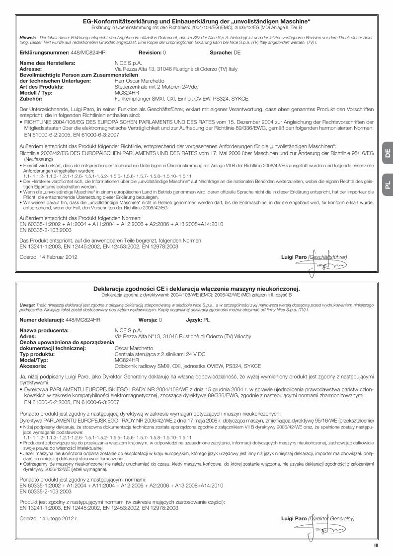
PL
DE
III
EG-Konformitätserklärung und Einbauerklärung der „unvollständigen Maschine“Erklärung in Übereinstimmung mit den Richtlinien: 2004/108/EG (EMC); 2006/42/EG (MD) Anlage II, Teil B
Hinweis - Der Inhalt dieser Erklärung entspricht den Angaben im offiziellen Dokument, das im Sitz der Nice S.p.A. hinterlegt ist und der letzten verfügbaren Revision vor dem Druck dieser Anlei-tung. Dieser Text wurde aus redaktionellen Gründen angepasst. Eine Kopie der ursprünglichen Erklärung kann bei Nice S.p.a. (TV) Italy angefordert werden. (TV) I.
Erklärungsnummer: 448/MC824HR Revision: 0 Sprache: DE
Name des Herstellers: NICE S.p.A.Adresse: Via Pezza Alta 13, 31046 Rustignè di Oderzo (TV) ItalyBevollmächtigte Person zum Zusammenstellen der technischen Unterlagen: Herr Oscar MarchettoArt des Produkts: Steuerzentrale mit 2 Motoren 24Vdc.Modell / Typ: MC824HRZubehör: Funkempfänger SMXI, OXI, Einheit OVIEW, PS324, SYKCE
Der Unterzeichnende, Luigi Paro, in seiner Funktion als Geschäftsführer, erklärt mit eigener Verantwortung, dass oben genanntes Produkt den Vorschriften entspricht, die in folgenden Richtlinien enthalten sind:
• RICHTLINIE 2004/108/EG DES EUROPÄISCHEN PARLAMENTS UND DES RATES vom 15. Dezember 2004 zur Angleichung der Rechtsvorschriften der Mitgliedsstaaten über die elektromagnetische Verträglichkeit und zur Aufhebung der Richtlinie 89/336/EWG, gemäß den folgenden harmonisierten Normen:
EN 61000-6-2:2005, EN 61000-6-3:2007
Außerdem entspricht das Produkt folgender Richtlinie, entsprechend der vorgesehenen Anforderungen für die „unvollständigen Maschinen“:
Richtlinie 2006/42/EG DES EUROPÄISCHEN PARLAMENTS UND DES RATES vom 17. Mai 2006 über Maschinen und zur Änderung der Richtlinie 95/16/EG (Neufassung)
• Hiermit wird erklärt, dass die entsprechenden technischen Unterlagen in Übereinstimmung mit Anlage VII B der Richtlinie 2006/42/EG ausgefüllt wurden und folgende essenzielle Anforderungen eingehalten wurden:
1.1- 1.1.2- 1.1.3- 1.2.1-1.2.6- 1.5.1-1.5.2- 1.5.5- 1.5.6- 1.5.7- 1.5.8- 1.5.10- 1.5.11• Der Hersteller verpflichtet sich, die Informationen über die „unvollständige Maschine“ auf Nachfrage an die nationalen Behörden weiterzuleiten, wobei die eignen Rechte des geis-
tigen Eigentums beibehalten werden. • Wenn die „unvollständige Maschine“ in einem europäischen Land in Betrieb genommen wird, deren offizielle Sprache nicht die in dieser Erklärung entspricht, hat der Importeur die
Pflicht, die entsprechende Übersetzung dieser Erklärung beizulegen.• Wir weisen darauf hin, dass die „unvollständige Maschine“ nicht in Betrieb genommen werden darf, bis die Endmaschine, in der sie eingebaut wird, für konform erklärt wurde,
entsprechend, wenn der Fall, den Vorschriften der Richtlinie 2006/42/EG.
Außerdem entspricht das Produkt folgenden Normen:EN 60335-1:2002 + A1:2004 + A11:2004 + A12:2006 + A2:2006 + A13:2008+A14:2010EN 60335-2-103:2003
Das Produkt entspricht, auf die anwendbaren Teile begrenzt, folgenden Normen:EN 13241-1:2003, EN 12445:2002, EN 12453:2002, EN 12978:2003
Oderzo, 14 Februar 2012 Luigi Paro (Geschäftsführer)
Deklaracja zgodności CE i deklaracja włączenia maszyny nieukończonej.Deklaracja zgodna z dyrektywami: 2004/108/WE (EMC); 2006/42/WE (MD) załącznik II, część B
Uwaga: Treść niniejszej deklaracji jest zgodna z oficjalną deklaracją zdeponowaną w siedzibie Nice S.p.a., a w szczególności z jej najnowszą wersją dostępną przed wydrukowaniem niniejszego podręcznika. Niniejszy tekst został dostosowany pod kątem wydawniczym. Kopię oryginalnej deklaracji zgodności można otrzymać od firmy Nice S.p.a. (TV) I.
Numer deklaracji: 448/MC824HR Wersja: 0 Język: PL
Nazwa producenta: NICE S.p.A.Adres: Via Pezza Alta N°13, 31046 Rustignè di Oderzo (TV) WłochyOsoba upoważniona do sporządzenia dokumentacji technicznej: Oscar MarchettoTyp produktu: Centrala sterująca z 2 silnikami 24 V DCModel/Typ: MC824HRAkcesoria: Odbiornik radiowy SMXI, OXI, jednostka OVIEW, PS324, SYKCE
Ja, niżej podpisany Luigi Paro, jako Dyrektor Generalny deklaruję na własną odpowiedzialność, że wyżej wymieniony produkt jest zgodny z następującymi dyrektywami:
• Dyrektywa PARLAMENTU EUROPEJSKIEGO I RADY NR 2004/108/WE z dnia 15 grudnia 2004 r. w sprawie ujednolicenia prawodawstwa państw człon-kowskich w zakresie kompatybilności elektromagnetycznej, znosząca dyrektywę 89/336/EWG, zgodnie z następującymi normami zharmonizowanymi:
EN 61000-6-2:2005, EN 61000-6-3:2007
Ponadto produkt jest zgodny z następującą dyrektywą w zakresie wymagań dotyczących maszyn nieukończonych:
Dyrektywa PARLAMENTU EUROPEJSKIEGO I RADY NR 2006/42/WE z dnia 17 maja 2006 r. dotycząca maszyn, zmieniająca dyrektywę 95/16/WE (przekształcenie)• Niżej podpisany deklaruje, że stosowna dokumentacja techniczna została sporządzona zgodnie z załącznikiem VII B dyrektywy 2006/42/WE oraz, że spełnione zostały następu-
jące wymagania podstawowe: 1.1- 1.1.2- 1.1.3- 1.2.1-1.2.6- 1.5.1-1.5.2- 1.5.5- 1.5.6- 1.5.7- 1.5.8- 1.5.10- 1.5.11• Producent zobowiązuje się do przekazania władzom krajowym, w odpowiedzi na uzasadnione zapytanie, informacji dotyczących maszyny nieukończonej, zachowując całkowicie
swoje prawa do własności intelektualnej. • Jeżeli maszyna nieukończona oddana zostanie do eksploatacji w kraju europejskim, którego język urzędowy jest inny niż język niniejszej deklaracji, importer ma obowiązek dołą-
czyć do niniejszej deklaracji stosowne tłumaczenie.• Ostrzegamy, że maszyny nieukończonej nie należy uruchamiać do czasu, kiedy maszyna końcowa, do której zostanie włączona, nie uzyska deklaracji zgodności z założeniami
dyrektywy 2006/42/WE (jeżeli wymagana).
Ponadto produkt jest zgodny z następującymi normami:EN 60335-1:2002 + A1:2004 + A11:2004 + A12:2006 + A2:2006 + A13:2008+A14:2010EN 60335-2-103:2003
Produkt jest zgodny z następującymi normami (w zakresie mających zastosowanie części):EN 13241-1:2003, EN 12445:2002, EN 12453:2002, EN 12978:2003
Oderzo, 14 lutego 2012 r. Luigi Paro (Dyrektor Generalny)

IV
NL
CE-conformiteitsverklaring en inbouwverklaring betreffende niet voltooide machinesVerklaring conform Richtlijnen: 2004/108/CE (EMC); 2006/42/EG (MD) bijlage II, deel B
Opmerking - De inhoud van deze verklaring komt overeen met hetgeen is vastgelegd in het officiële document dat is gedeponeerd ten kantore van Nice S.p.a., en in het bijzonder met de laatste herziene en beschikbare versie ervan, vóór het drukken van deze handleiding. De hier gepresenteerde tekst is herzien om redactionele redenen. Een exemplaar van de oorspronkelijke verklaring kan worden aangevraagd bij Nice S.p.a. (TV) Italië.
Nummer verklaring: 448/MC824HR Revisie: 0 Taal: NL
Firmanaam: NICE S.p.A.Adres: Via Pezza Alta 13, 31046 Rustignè di Oderzo (TV) ItaliëPersoon gemachtigd tot het samenstellen van het technisch dossier: Dhr. Oscar MarchettoType product: Besturingseenheid met 2 motoren 24Vd.c.Model / Type: MC824HRAccessoires: Radio-ontvanger SMXI, OXI, OVIEW-eenheid, PS324, SYKCE
Ondergetekende Luigi Paro verklaart onder eigen verantwoordelijkheid als Gedelegeerd Directeur dat het product voldoet aan de vereisten van de hierop volgende richtlijnen:
• RICHTLIJN 2004/108/CE VAN HET EUROPEES PARLEMENT EN DE RAAD VAN DE EUROPESE UNIE van 15 december 2004 betreffende de onderlinge aanpassing van de wetgevingen van de lidstaten inzake electromagnetische compatibiliteit en tot wijziging van richtlijn 89/336/EEG, volgens de hieropvol-gende geharmoniseerde normen:
EN 61000-6-2:2005, EN 61000-6-3:2007
Bovendien voldoet het product aan de hieropvolgende richtlijn volgens de voor "pseudo machines" geldende vereisten:
Richtlijn 2006/42/EG VAN HET EUROPEES PARLEMENT EN DE RAAD VAN DE EUROPESE UNIE van 17 mei 2006 betreffende machines en tot wijziging van Richtlijn 95/16/EG (herschikking)• Hierbij verklaart men dat het relevante techinische dossier is ingevuld volgens de aanwijzingen in bijlage VII B van de richtlijn 2006/42/EG en dat daarbij aan de hierop volgende
verplichte eisen is voldaan: 1.1- 1.1.2- 1.1.3- 1.2.1-1.2.6- 1.5.1-1.5.2- 1.5.5- 1.5.6- 1.5.7- 1.5.8- 1.5.10- 1.5.11• De fabrikant zal zorgdragen voor de overdracht van informatie bertreffende de niet voltooide machine, op speciaal verzoek van de wetgevende instanties zonder daarbij schade te
doen toekomen aan zijn eigen intellectueel eigendomsrecht. • Mocht de onvoltooide machine in gebruik worden genomen in een land waar een andere taal wordt gesproken dan in deze verklaring is gebruikt, is de importeur verplicht de
vertaling van het desbetreffende document aan de documentatie toe te voegen.• Het is niet toegestaan de niet voltooide machine in gebruik te nemen voordat de uiteindelijke machine waarop deze zal worden ingebouwd, en indien van toepassing geschikt is
verklaard volgens de richtlijn 2006/42/EG.
Bovendien voldoet het product aan de hierop volgende normen:EN 60335-1:2002 + A1:2004 + A11:2004 + A12:2006 + A2:2006 + A13:2008+A14:2010EN 60335-2-103:2003
Het product voldoet, waar van toepassing, aan de hierop volgende normen:EN 13241-1:2003, EN 12445:2002, EN 12453:2002, EN 12978:2003
Oderzo, 14 februari 2012 Luigi Paro (Gedelegeerd Directeur)

EN
English – V
Instructions and warnings for the user
Before using the automation for the first time, ask the installer to explain the origin of residual risks and devote a few minutes to reading this user instruction and warning manual given to you by the installer. Keep the manual for reference when in doubt and pass it on to new owners of the automation.
IMPORTANT! – Your automation is a machine that performs your commands faithfully; negligent or improper use may constitute a hazard.
– Never activate automation controls if persons, animals or objects are present in the operating range.
– NEVER touch parts of the automation while the gate or door is moving!
– Photocells are not safety devices but safety aids. They are constructed with very reliable technology but in extreme situ-ations they may malfunction or even break. In some cases this malfunction may not be immediately evident. For this reason, observe the following warnings when using the automation:
- Pass through the gate or door only when it is completely open and the leafs have stopped moving.
- NEVER pass through while the gate or door is closing!
- Periodically check correct operation of the photocells.
• Children: an automation system guarantees a high level of safety, using a special detection system to prevent movement in the pres-ence of persons or objects. Nonetheless, it is advisable to ensure that children do not play in the vicinity of the automation. To prevent the risk of accidental activation, do not leave the remote controls within the reach of children It is not a game!
• The product should not be used by children or people with impaired physical, sensorial or mental capacities or who have not received ade-quate training in the safe use of the product.
• Malfunctions: if the automation is seen to perform abnormally, disconnect the electrical power supply from the system and manu-ally release the gearmotor (see instruction manual) to operate the gate manually. Never attempt to perform repairs; contact your local installer for assistance.
• Never modify the system or the control unit programming and adjustment parameters: this is the responsibility of the installer.
• Power supply failure or absence: while waiting for the installer or the electrical power supply to return, the automation can still be used even if the system is not equipped with a buffer battery: manually release the gearmotor (see instruction manual) and move the gate leaf manually as required.
• Safety devices disabled: the automation can be operated even when a safety device does not work correctly or is out of use. The gate can be controlled in the “hold-to-run” mode. Proceed as follows:
01. Send a command to operate the gate using a transmitter or a key selector, etc. If everything operates correctly, the gate will move normally, otherwise proceed as follows;
02. Within 3 seconds, activate the control again and keep it activated;
03. After approximately 2 seconds, the gate will perform the required movement in “hold-to-run”; mode; i.e. the gate will continue to move only as long as the control is activated.
IMPORTANT! – If the safety devices are out of use, it is advis-able to have them repaired as quickly as possible by a qualified technician.
• Testing, periodic maintenance and any repairs must be documented by the person performing the operations and the relevant documents must be kept by the system owner. The only operations that can be performed by the user are to clean the photocell lenses (use a soft and slightly damp cloth) and remove any leaves or stones that may obstruct the automation. Important – To prevent the door from being
activated accidentally, before proceeding release the automation manually (as described in the relevant manual).
• Maintenance: Regular maintenance (at least every 6 months) is needed to keep the level of safety constant and to ensure the maxi-mum durability of the entire automation. Checks, maintenance and repairs must be performed exclusively by qualified personnel.
• Disposal: At the end of the automation’s lifetime, ensure that it is disposed by qualified personnel and that the materials are recycled or scrapped according to current local standards.
• If the automation has been blocked by a “Block automation” command: after sending a command, the gate does not move and the flashing light emits 9 short flashes.
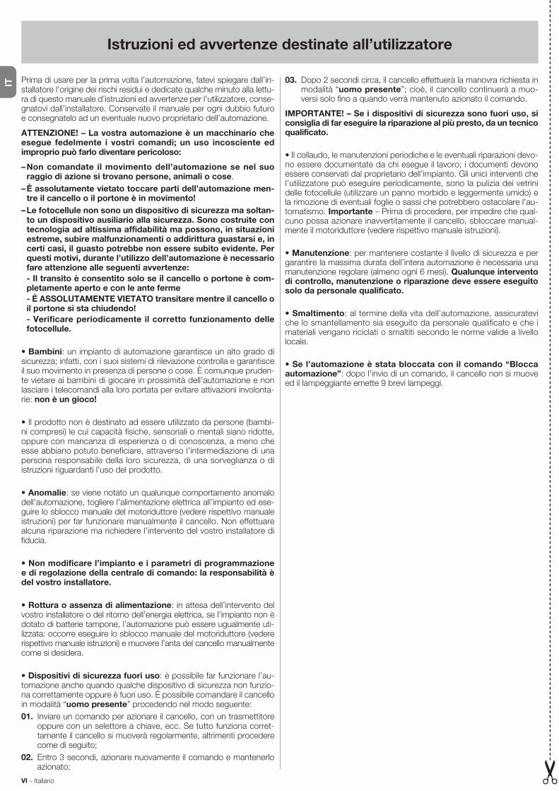
Istruzioni ed avvertenze destinate all’utilizzatore
Prima di usare per la prima volta l’automazione, fatevi spiegare dall’in-stallatore l’origine dei rischi residui e dedicate qualche minuto alla lettu-ra di questo manuale d’istruzioni ed avvertenze per l’utilizzatore, conse-gnatovi dall’installatore. Conservate il manuale per ogni dubbio futuro e consegnatelo ad un eventuale nuovo proprietario dell’automazione.
ATTENZIONE! – La vostra automazione è un macchinario che esegue fedelmente i vostri comandi; un uso incosciente ed improprio può farlo diventare pericoloso:
– Non comandate il movimento dell’automazione se nel suo raggio di azione si trovano persone, animali o cose.
– È assolutamente vietato toccare parti dell’automazione men-tre il cancello o il portone è in movimento!
– Le fotocellule non sono un dispositivo di sicurezza ma soltan-to un dispositivo ausiliario alla sicurezza. Sono costruite con tecnologia ad altissima affidabilità ma possono, in situazioni estreme, subire malfunzionamenti o addirittura guastarsi e, in certi casi, il guasto potrebbe non essere subito evidente. Per questi motivi, durante l’utilizzo dell’automazione è necessario fare attenzione alle seguenti avvertenze:
- Il transito è consentito solo se il cancello o portone è com-pletamente aperto e con le ante ferme
- È ASSOLUTAMENTE VIETATO transitare mentre il cancello o il portone si sta chiudendo!
- Verificare periodicamente il corretto funzionamento delle fotocellule.
• Bambini: un impianto di automazione garantisce un alto grado di si curezza; infatti, con i suoi sistemi di rilevazione controlla e garantisce il suo movimento in presenza di persone o cose. È comunque pruden-te vietare ai bambini di giocare in prossimità dell’automazione e non lasciare i telecomandi alla loro portata per evitare attivazioni involonta-rie: non è un gioco!
• Il prodotto non è destinato ad essere utilizzato da persone (bambi-ni compresi) le cui capacità fisiche, sensoriali o mentali siano ridotte, oppure con mancanza di esperienza o di conoscenza, a meno che esse abbiano potuto beneficiare, attraverso l’intermediazione di una persona responsabile della loro sicurezza, di una sorveglianza o di istruzioni riguardanti l’uso del prodotto.
• Anomalie: se viene notato un qualunque comportamento anomalo dell’automazione, togliere l’alimentazione elettrica all’impianto ed ese-guire lo sblocco manuale del motoriduttore (vedere rispettivo manuale istruzioni) per far funzionare manualmente il cancello. Non effettuare alcuna riparazione ma richiedere l’intervento del vostro installatore di fiducia.
• Non modificare l’impianto e i parametri di programmazione e di regolazione della centrale di comando: la responsabilità è del vostro installatore.
• Rottura o assenza di alimentazione: in attesa dell’intervento del vostro installatore o del ritorno dell’energia elettrica, se l’impianto non è dotato di batterie tampone, l’automazione può essere ugualmente uti-lizzata: occorre eseguire lo sblocco manuale del motoriduttore (vedere rispettivo manuale istruzioni) e muovere l’anta del cancello manualmente come si desidera.
• Dispositivi di sicurezza fuori uso: è possibile far funzionare l’au-tomazione anche quando qualche dispositivo di sicurezza non funzio-na correttamente oppure è fuori uso. È possibile comandare il cancello in modalità “uomo presente” procedendo nel modo seguente:
01. Inviare un comando per azionare il cancello, con un trasmettitore oppure con un selettore a chiave, ecc. Se tutto funziona corret-tamente il cancello si muoverà regolarmente, altrimenti procedere come di seguito;
02. Entro 3 secondi, azionare nuovamente il comando e mantenerlo azionato;
03. Dopo 2 secondi circa, il cancello effettuerà la manovra ri chiesta in modalità “uomo presente”; cioè, il cancello continuerà a muo-versi solo fino a quando verrà mantenuto azionato il comando.
IMPORTANTE! – Se i dispositivi di sicurezza sono fuori uso, si consiglia di far eseguire la riparazione al più presto, da un tecnico qualificato.
• Il collaudo, le manutenzioni periodiche e le eventuali riparazioni devo-no essere documentate da chi esegue il lavoro; i documenti devono essere conservati dal proprietario dell’impianto. Gli unici interventi che l’utilizzatore può eseguire periodicamente, sono la pulizia dei vetrini delle fotocellule (utilizzare un panno morbido e leggermente umido) e la rimozione di eventuali foglie o sassi che potrebbero ostacolare l’au-tomatismo. Importante – Prima di procedere, per impedire che qual-cuno possa azionare inavvertitamente il cancello, sbloccare manual-mente il motoriduttore (vedere rispettivo manuale istruzioni).
• Manutenzione: per mantenere costante il livello di sicurezza e per garantire la massima durata dell’intera automazione è necessaria una manutenzione regolare (almeno ogni 6 mesi). Qualunque intervento di controllo, manutenzione o riparazione deve essere eseguito solo da personale qualificato.
• Smaltimento: al termine della vita dell’automazione, assicuratevi che lo smantellamento sia eseguito da personale qualificato e che i materiali vengano riciclati o smaltiti secondo le norme valide a livello locale.
• Se l’automazione è stata bloccata con il comando “Blocca automazione”: dopo l’invio di un comando, il cancello non si muove ed il lampeggiante emette 9 brevi lampeggi.
VI – Italiano
IT

Instructions et recommandations destinées à l’utilisateur
Avant d’utiliser pour la première fois l’automatisme, faites-vous expli-quer par l’installateur l’origine des risques résiduels et consacrez quelques minutes à la lecture de ce guide d’instructions et d’avertis-sements pour l’utilisateur qui vous est remis par l’installateur. Conser-vez le guide pour pouvoir le consulter dans le futur, en cas de doute, et remettez-le, le cas échéant, au nouveau propriétaire de l’automa-tisme ;
ATTENTION ! – Votre automatisme est un équipement qui exé-cute fidèlement vos commandes ; une utilisation inconsciente et incorrecte peut le rendre dangereux.
– Ne commandez pas le mouvement de l’automatisme si des personnes, des animaux ou des objets se trouvent dans son rayon d’action.
– Il est absolument interdit de toucher des parties de l’automa-tisme quand le portail ou la porte sont en mouvement !
– Les photocellules ne sont pas un dispositif de sécurité mais uniquement un dispositif auxiliaire à la sécurité. Elles sont construites avec des technologies à très haute fiabilité mais peuvent présenter, dans des situations extrêmes, des pro-blèmes de fonctionnement ou tomber en panne, et dans certains cas, l’avarie pourrait ne pas être évidente immédia-tement. C’est la raison pour laquelle, durant l’utilisation de l’automatisme, il faut faire attention aux recommandations suivantes :
- Le transit n’est autorisé que si le portail (ou la porte) est complètement ouvert et les vantaux immobiles
- IL EST ABSOLUMENT INTERDIT de transiter quand le portail ou la porte est en train de se fermer !
- Vérifier périodiquement le fonctionnement correct des pho-tocellules.
• Enfants : cette installation d’automatisation garantit un haut niveau de sécurité ; en effet, grâce à ses systèmes de détection, elle contrôle et garantit la manœuvre en présence de personnes ou de choses. Il est prudent toutefois d’éviter de laisser jouer les enfants à proximité de l’automatisme et pour éviter les activations involontaires, il ne faut pas laisser les émetteurs à leur portée : ce n’est pas un jeu !
• Le produit n’est pas destiné à être utilisé par des personnes (enfants compris) aux capacités physiques, sensorielles ou mentales réduites, ou manquant d’expérience ou de connaissances, à moins que celles-ci aient pu bénéficier, par l’intermédiaire d’une personne responsable de leur sécurité, d’une surveillance ou d’instructions sur l’utilisation du produit.
• Anomalies : si le moindre comportement anormal de l’automa-tisme est détecté, couper l’alimentation électrique de l’installation et débrayer manuellement l’opérateur (voir guide d’instructions respectif) pour faire fonctionner manuellement le portail. Ne jamais tenter de le réparer mais contacter l’installateur de confiance.
• Ne pas modifier l’installation ni les paramètres de program-mation et de réglage de la logique de commande : la responsa-bilité en incombe à l’installateur.
• Rupture ou absence d’alimentation électrique : en attendant l’intervention de l’installateur, ou le retour du courant si l’installation est dépourvue de batterie tampon, l’automatisme peut être actionné comme n’importe quel autre système non automatisé. il suffit d’ac-tionner le débrayage de l’opérateur (voir le guide d’instructions) et de bouger manuellement le vantail dans le sens désiré.
• Dispositifs de sécurité hors d’usage : il est possible de faire fonc-tionner l’automatisme même quand l’un des dispositifs de sécurité ne fonctionne pas correctement ou est hors d’usage. Il est possible de commander le portail avec « commande à action maintenue », en procédant de la façon suivante :
01. Envoyer une commande pour actionner le portail, avec un émet-teur ou avec un sélecteur à clé, etc. Si tout fonctionne correcte-
ment, le portail bougera régulièrement, en cas contraire procéder comme suit :
02. Dans les 3 secondes qui suivent, actionner de nouveau la com-mande et la maintenir ;
03. Au bout de 2 secondes environ, le portail effectuera la manœuvre désirée en mode « action maintenue » c’est-à-dire que l’action-nement du portail ne se vérifiera que tant que la commande est maintenue.
IMPORTANT ! – Si les dispositifs de sécurité sont hors d’usage, il est conseillé de faire la réparation au plus tôt, par un techni-cien qualifié.
• L’essai de fonctionnement final, les maintenances périodiques et les éventuelles réparations doivent être documentés par la personne qui effectue le travail et les documents doivent être conservés par le propriétaire de l’installation. Les seules interventions que l’utilisa-teur peut effectuer périodiquement sont le nettoyage des verres des photocellules (utiliser un chiffon doux et légèrement humide) et l’éli-mination des feuilles et des cailloux qui pourraient bloquer l’automa-tisme. Important – Avant de procéder, pour empêcher que quelqu’un puisse actionner accidentellement le portail, débrayer manuellement l’opérateur (voir le guide d’instructions).
• Maintenance : pour maintenir un niveau de sécurité constant et pour garantir la durée maximum de tout l’automatisme, il faut effectuer une maintenance régulière (au moins tous les 6 mois). Toute inter-vention de contrôle, maintenance ou réparation doit être exé-cutée exclusivement par du personnel qualifié.
Mise au rebut : à la fin de la vie de l’automatisme, assurez-vous que le démantèlement est effectué par du personnel qualifié et que les matériaux sont recyclés ou mis au rebut en respectant les normes locales en vigueur.
• Si l’automatisme a été bloqué avec la commande « Blocage de l’automatisme » : après l’envoi d’une commande, le portail ne bouge pas et le clignotant émet 9 clignotements brefs.
Français – VII
FR

Instrucciones y advertencias destinadas al usuario
Antes de utilizar por primera vez el automatismo, pida a su instalador que le explique el origen de los riesgos residuales y lea este manual de instrucciones y advertencias para el usuario entregado por el insta-lador. Conserve el manual por cualquier problema que pueda surgir y recuerde entregarlo al nuevo dueño del automatismo.
¡ATENCIÓN! – El automatismo es una máquina que ejecuta fiel-mente los mandos dados: un uso inconsciente e inadecuado puede ser peligroso:
– Por consiguiente, no accione el automatismo cuando en su radio de acción haya personas, animales o cosas.
– Está terminantemente prohibido tocar las piezas del automa-tismo mientras la cancela o el portón se estén moviendo.
– Las fotocélulas no son un dispositivo de seguridad sino que son sólo un dispositivo auxiliar de seguridad. Están fabri-cadas con tecnología de alta fiabilidad pero, en situaciones extremas, pueden funcionar mal o averiarse y, en determina-dos casos, la avería podría estar oculta. Por dichos motivos, durante el uso del automatismo es necesario tener cuidado con las siguientes advertencias:
- El tránsito está permitido sólo si la cancela o el portón están completamente abiertos o con las hojas detenidas.
- ESTÁ TERMINANTEMENTE PROHIBIDO transitar mientras la cancela o el portón se están cerrando.
- Controle periódicamente que las fotocélulas funcionen correctamente.
• Niños: una instalación de automatización garantiza un elevado grado de seguridad; en efecto, gracias a sus sistemas de detección, controla y garantiza que no se mueva ante la presencia de personas o cosas. Procure que los niños no jueguen cerca del automatismo y mantenga los controles remotos lejos de su alcance para evitar que sean activados: ¡no son un juguete!
• El producto no está destinado para ser utilizado por personas (niños incluidos) cuyas capacidades físicas, sensoriales o mentales sean reducidas, o sin experiencia ni conocimientos, salvo que dichas per-sonas estén acompañadas por una persona responsable de su segu-ridad o hayan sido instruidas sobre el uso del producto.
• Desperfectos: ni bien note que el automatismo no funciona correc-tamente, corte la alimentación eléctrica de la instalación y realice el desbloqueo manual del motorreductor (véase el manual de instruccio-nes correspondiente) para hacer funcionar manualmente la cancela. No realice ninguna reparación sino que solicite el servicio de su insta-lador de confianza.
• No modifique la instalación ni los parámetros de programa-ción y de regulación de la central de mando: la responsabilidad es del instalador.
• Rotura o falta de alimentación: mientras espera que llegue el ins-talador o que vuelva la energía eléctrica, si la instalación no incorporara baterías compensadoras, el automatismo se puede utilizar igualmente: habrá que desbloquear a mano el motorreductor (véase el manual de instrucciones correspondiente) y mover manualmente la hoja de la can-cela.
• Dispositivos de seguridad fuera de uso: es posible hacer fun-cionar el automatismo incluso cuando algún dispositivo de seguridad no funciona correctamente o está fuera de uso. Es posible accionar la cancela en modalidad “hombre presente” procediendo de la siguiente manera:
01. Envíe un mando para accionar la cancela con un transmisor o con un selector de llave, etc.. Si todo funciona correctamente, la can-cela se moverá regularmente, en caso contrario, siga estos pasos;
02. Antes de 3 segundos, accione nuevamente el mando y mantén-galo accionado;
03. Después de 2 segundos aprox., la cancela realizará el movimiento
re querido en modalidad “hombre presente”, es decir que la can-cela se guirá moviéndose sólo hasta que se mantenga accionado el mando.
¡IMPORTANTE! – Si los dispositivos de seguridad estuvieran fue-ra de uso, se aconseja hacerlos reparar lo antes posible por un técnico cualificado.
• El ensayo, las operaciones de mantenimiento periódico y las repara-ciones deben ser documentados por la persona que realiza el trabajo; los documentos deben ser conservados por el dueño de la instala-ción. Las únicas operaciones que el usuario puede realizar periódica-mente son la limpieza de los cristales de las fotocélulas (con un paño suave y ligeramente húmedo) y la eliminación de las hojas y piedras que podrían obstaculizar el automatismo. Importante – Antes de pro-ceder, para impedir que alguien pueda accionar inadvertidamente la cancela, desbloquee manualmente el motorreductor (véase el manual de instrucciones respectivo).
• Mantenimiento: para mantener el nivel de seguridad constan-te y para garantizar la duración máxima de toda la automatización, es necesario efectuar un mantenimiento regular (al menos cada 6 meses). Cualquier operación de control, mantenimiento o repa-ración debe ser realizada únicamente por personal cualificado.
• Desguace: al final de la vida útil del automatismo, el desguace debe ser realizado por personal cualificado y los materiales deben ser reci-clados o eliminados según las normas locales vigentes.
• Si el automatismo ha sido bloqueado con el mando “Bloquear automatismo”: después de enviar un mando, la cancela no se move-rá y la luz intermitente emitirá 9 destellos cortos.
VIII – Español
ES

Anweisungen und Hinweise für den Benutzer
Bevor Sie die Automatisierung zum ersten Mal verwenden, lassen Sie sich von Ihrem Installateur erklären, wie Restrisiken entstehen können, und widmen Sie dem Lesen der Anweisungen und Hinweise für den Benutzer, die Ihnen Ihr Installateur aushändigen wird, ein paar Minu-ten. Bewahren Sie die Anleitung für zukünftige Zweifelsfälle auf und übergeben Sie diese ggf. einem neuen Besitzer der Automatisierung.
ACHTUNG! - Ihre Automatisierung ist eine Maschine, die Ihre Be fehle getreu durchführt; ein verantwortungsloser und unsachgemäßer Gebrauch kann gefährlich werden:
– Steuern Sie die Bewegung der Automatisierung nicht, wenn sich in ihrem Wirkungskreis Personen, Tiere oder Gegenstän-de befinden.
– Es ist absolut verboten, Teile der Automatisierung zu berüh-ren, we nn das Tor in Bewegung ist!
–Die Lichtschranken sind keine Sicherheitsvorrichtungen, son-dern stellen nur eine zusätzliche Sicherheit dar. Sie wurden mit einer höchst zuverlässigen Technologie gebaut, können aber unter extremen Bedingungen mangelhaft funktionieren oder sogar ausfallen; in einigen Fällen könnte der Mangel nicht sofort ersichtlich sein. Aus diesen Gründen ist es bei der Anwendung der Automatisierung notwendig, die folgenden Hinweise zu beachten:
- Der Durchgang ist nur erlaubt, wenn das Tor vollständig geöffnet ist und die Flügel still stehen.
- ES IST ABSOLUT VERBOTEN, durch das Tor zu schreiten, wenn es geschlossen wird!
- Regelmäßig die Funktionstüchtigkeit der Lichtschranken prüfen.
• Kinder: eine Automatisierungsanlage gewährleistet einen hohen Sicherheitsgrad und verhindert mit ihren Schutzsystemen, dass sie sich bei An wesenheit von Personen und Gegenständen bewegt. Als Vorsichtsmaßnahme sollte man aber Kindern verbieten, in der Nähe der Automatisierung zu spielen, und man sollte die Fernbedienungen nicht in der Reichweite von Kindern lassen, damit unerwünschte Betä-tigungen verhindert werden: es handelt sich nicht um ein Spiel!
• Das Produkt ist nicht dafür bestimmt, von Personen (einschließlich Kinder) angewendet zu werden, deren körperliche, empfindungsbe-zogene oder geistige Fähigkeiten eingeschränkt sind, oder wenn kei-ne Erfahrung oder Kenntnis vorliegt, außer wenn diese durch eine für ihre Sicherheit verantwortliche Person überwacht und bezüglich der Anwendung des Produkts angewiesen werden.
• Störungen: Wenn ein unnormales Verhalten der Automatisierung festgestellt wird, muss die Stromspeisung der Anlage unterbrochen und ein manuelles Lösen des Torantriebs vorgenommen werden (sie-he diesbezügliche Gebrauchsanleitung), um das Tor von Hand bedie-nen zu können. Versuchen Sie nie, selbst Reparaturen auszuführen, sondern fordern Sie den Eingriff Ihres Vertrauensinstallateurs an.
• Die Anlage und die Programmierungs- und Einstellungspara-meter der Steuerung nicht ändern: diese Verantwortung steht Ihrem Installateur zu.
• Bruch oder keine Speisung: In Erwartung Ihres Installateurs oder der Rückkehr des Stroms und wenn die Anlage keine Pufferbatterie aufweist, kann die Automatisierung trotzdem genutzt werden: Das manuelle Lösen des Torantriebs muss vorgenommen (siehe diesbe-zügliche Gebrauchsanleitung) und der Flügel des Tors von Hand wie gewünscht bewegt werden.
• Sicherheitsvorrichtungen außer Betrieb: Es ist möglich, die Automatisierung auch in Betrieb zu setzen, wenn eine Sicherheits-vorrichtung nicht korrekt funktioniert oder außer Betrieb ist. Es ist möglich, das Tor auch im Modus “Todmannfunktion” wie folgt zu steuern:
01. Einen Befehl zur Betätigung des Tors übersenden, mithilfe eines Senders oder mit einem Schlüsseltaster, usw. Wenn alles korrekt
funktioniert, bewegt sich das Tor regulär, ansonsten wie folgt vor-gehen;
02. Die Schaltvorrichtung innerhalb von 3 Sekunden erneut betätigen und weiter betätigen;
03. Nach zirka 2 Sekunden führt das Tor die geforderte Bewegung im Mo dus “Todmannfunktion” aus; d.h. das Tor bewegt sich weiter, so lange dieser Befehl beibehalten wird.
Entsorgung! – Wenn die Sicherheitsvorrichtungen außer Betrieb sind, empfehlen wir, die Reparatur so bald wie möglich durch einen qualifizierten Techniker ausführen zu lassen.
• Die Endabnahme, die regelmäßigen Wartungen und eventuelle Reparaturen müssen von dem, der diese Arbeiten ausführt, belegt sein, und diese Belege müssen vom Besitzer der Anlage aufbewahrt werden. Die einzigen Eingriffe, die Sie ausführen und regelmäßig auch ausführen sollten, sind die Reinigung der Gläser an den Lichtschran-ken (mit einem weichen und leicht feuchten Tuch) und die Entfernung eventueller Blätter oder Steine, die die Automatisierung behindern könnten. Wichtig – Bevor fortgeschritten wird, muss zur Verhinde-rung, dass jemand das Tor ungewollt betätigen kann, der Torantrieb von Hand gelöst werden (siehe diesbezügliche Gebrauchsanleitung).
• Wartung: Um das Sicherheitsniveau konstant zu halten und die längste Lebensdauer der ganzen Automatisierung zu gewährleisten, ist eine regelmäßige Wartung erforderlich (mindestens alle 6 Monate). Arbeiten wie Wartung, Kontrollen und Reparaturen dürfen nur von Fachpersonal ausgeführt werden.
• Entsorgung: Versichern Sie sich, dass die Entsorgung am Ende der Lebensdauer Ihrer Automatisierung von Fachpersonal gemacht wird und dass die Materialien nach den örtlich gültigen Vorschriften recyc-led oder entsorgt werden.
• Wenn die Automatisierung mit dem Befehl “Blockieren der Automatisierung” blockiert wurde: Nach der Übersendung eines Befehls bewegt sich das Tor nicht und die Blinkleuchte blinkt 9 Mal kurz.
Deutsch – IX
DE
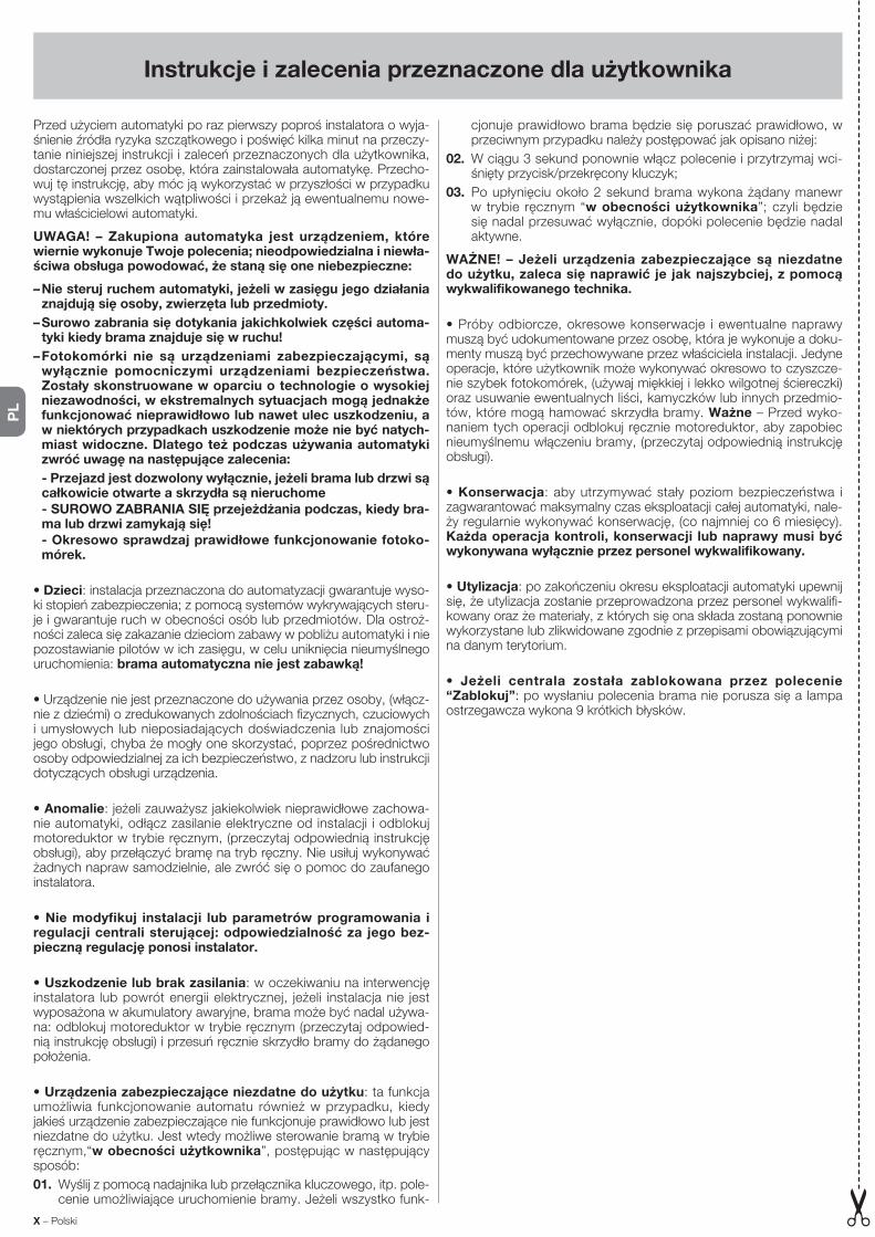
Instrukcje i zalecenia przeznaczone dla użytkownika
Przed użyciem automatyki po raz pierwszy poproś instalatora o wyja-śnienie źródła ryzyka szczątkowego i poświęć kilka minut na przeczy-tanie niniejszej instrukcji i zaleceń przeznaczonych dla użytkownika, dostarczonej przez osobę, która zainstalowała automatykę. Przecho-wuj tę instrukcję, aby móc ją wykorzystać w przyszłości w przypadku wystąpienia wszelkich wątpliwości i przekaż ją ewentualnemu nowe-mu właścicielowi automatyki.
UWAGA! – Zakupiona automatyka jest urządzeniem, które wiernie wykonuje Twoje polecenia; nieodpowiedzialna i niewła-ściwa obsługa powodować, że staną się one niebezpieczne:
– Nie steruj ruchem automatyki, jeżeli w zasięgu jego działania znajdują się osoby, zwierzęta lub przedmioty.
– Surowo zabrania się dotykania jakichkolwiek części automa-tyki kiedy brama znajduje się w ruchu!
– Fotokomórki nie są urządzeniami zabezpieczającymi, są wyłącznie pomocniczymi urządzeniami bezpieczeństwa. Zostały skonstruowane w oparciu o technologie o wysokiej niezawodności, w ekstremalnych sytuacjach mogą jednakże funkcjonować nieprawidłowo lub nawet ulec uszkodzeniu, a w niektórych przypadkach uszkodzenie może nie być natych-miast widoczne. Dlatego też podczas używania automatyki zwróć uwagę na następujące zalecenia:
- Przejazd jest dozwolony wyłącznie, jeżeli brama lub drzwi są całkowicie otwarte a skrzydła są nieruchome
- SUROWO ZABRANIA SIĘ przejeżdżania podczas, kiedy bra-ma lub drzwi zamykają się!
- Okresowo sprawdzaj prawidłowe funkcjonowanie fotoko-mórek.
• Dzieci: instalacja przeznaczona do automatyzacji gwarantuje wyso-ki stopień zabezpieczenia; z pomocą systemów wykrywających steru-je i gwarantuje ruch w obecności osób lub przedmiotów. Dla ostroż-ności zaleca się zakazanie dzieciom zabawy w pobliżu automatyki i nie pozostawianie pilotów w ich zasięgu, w celu uniknięcia nieumyślnego uruchomienia: brama automatyczna nie jest zabawką!
• Urządzenie nie jest przeznaczone do używania przez osoby, (włącz-nie z dziećmi) o zredukowanych zdolnościach fizycznych, czuciowych i umysłowych lub nieposiadających doświadczenia lub znajomości jego obsługi, chyba że mogły one skorzystać, poprzez pośrednictwo osoby odpowiedzialnej za ich bezpieczeństwo, z nadzoru lub instrukcji dotyczących obsługi urządzenia.
• Anomalie: jeżeli zauważysz jakiekolwiek nieprawidłowe zachowa-nie automatyki, odłącz zasilanie elektryczne od instalacji i odblokuj motoreduktor w trybie ręcznym, (przeczytaj odpowiednią instrukcję obsługi), aby przełączyć bramę na tryb ręczny. Nie usiłuj wykonywać żadnych napraw samodzielnie, ale zwróć się o pomoc do zaufanego instalatora.
• Nie modyfikuj instalacji lub parametrów programowania i regulacji centrali sterującej: odpowiedzialność za jego bez-pieczną regulację ponosi instalator.
• Uszkodzenie lub brak zasilania: w oczekiwaniu na interwencję instalatora lub powrót energii elektrycznej, jeżeli instalacja nie jest wyposażona w akumulatory awaryjne, brama może być nadal używa-na: odblokuj motoreduktor w trybie ręcznym (przeczytaj odpowied-nią instrukcję obsługi) i przesuń ręcznie skrzydło bramy do żądanego położenia.
• Urządzenia zabezpieczające niezdatne do użytku: ta funkcja umożliwia funkcjonowanie automatu również w przypadku, kiedy jakieś urządzenie zabezpieczające nie funkcjonuje prawidłowo lub jest niezdatne do użytku. Jest wtedy możliwe sterowanie bramą w trybie ręcznym,“w obecności użytkownika”, postępując w następujący sposób:
01. Wyślij z pomocą nadajnika lub przełącznika kluczowego, itp. pole-cenie umożliwiające uruchomienie bramy. Jeżeli wszystko funk-
cjonuje prawidłowo brama będzie się poruszać prawidłowo, w przeciwnym przypadku należy postępować jak opisano niżej:
02. W ciągu 3 sekund ponownie włącz polecenie i przytrzymaj wci-śnięty przycisk/przekręcony kluczyk;
03. Po upłynięciu około 2 sekund brama wykona żądany manewr w trybie ręcznym “w obecności użytkownika”; czyli będzie się nadal przesuwać wyłącznie, dopóki polecenie będzie nadal aktywne.
WAŻNE! – Jeżeli urządzenia zabezpieczające są niezdatne do użytku, zaleca się naprawić je jak najszybciej, z pomocą wykwalifikowanego technika.
• Próby odbiorcze, okresowe konserwacje i ewentualne naprawy muszą być udokumentowane przez osobę, która je wykonuje a doku-menty muszą być przechowywane przez właściciela instalacji. Jedyne operacje, które użytkownik może wykonywać okresowo to czyszcze-nie szybek fotokomórek, (używaj miękkiej i lekko wilgotnej ściereczki) oraz usuwanie ewentualnych liści, kamyczków lub innych przedmio-tów, które mogą hamować skrzydła bramy. Ważne – Przed wyko-naniem tych operacji odblokuj ręcznie motoreduktor, aby zapobiec nieumyślnemu włączeniu bramy, (przeczytaj odpowiednią instrukcję obsługi).
• Konserwacja: aby utrzymywać stały poziom bezpieczeństwa i zagwarantować maksymalny czas eksploatacji całej automatyki, nale-ży regularnie wykonywać konserwację, (co najmniej co 6 miesięcy). Każda operacja kontroli, konserwacji lub naprawy musi być wykonywana wyłącznie przez personel wykwalifikowany.
• Utylizacja: po zakończeniu okresu eksploatacji automatyki upewnij się, że utylizacja zostanie przeprowadzona przez personel wykwalifi-kowany oraz że materiały, z których się ona składa zostaną ponownie wykorzystane lub zlikwidowane zgodnie z przepisami obowiązującymi na danym terytorium.
• Jeżeli centrala została zablokowana przez polecenie “Za blokuj”: po wysłaniu polecenia brama nie porusza się a lampa ostrzegawcza wykona 9 krótkich błysków.
X – Polski
PL

Aanwijzingen en aanbevelingen voor de gebruiker
Laat u, voordat u de automatisering voor de eerste keer gaat gebrui-ken, door de installateur uitleggen welke restrisico’s er zijn en besteed een paar minuten aan het doorlezen van deze handleiding met aanwij-zingen en aanbevelingen voor de gebruiker die de installateur u heeft overhandigd. Bewaar deze handleiding voor eventuele toekomstige twijfels en geef haar aan een eventuele nieuwe eigenaar van de auto-matisering.
LET OP! – Uw automatisering is een machine die uw instructies trouw uitvoert; een onverantwoordelijk en oneigenlijk gebruik ervan kan hem echter tot een gevaar maken:
– Zet de automatisering nooit in beweging indien er zich perso-nen, dieren of voorwerpen in diens actieradius bevinden.
– Het is ten strengste verboden delen van de automatisering aan te raken terwijl de poort of deur in beweging is!
– De fotocellen zijn geen veiligheidsinrichting, maar uitsluitend een hulpmiddel voor de veiligheid. Ze zijn gebouwd volgens een uiterst betrouwbare technologie maar kunnen, in extre-me situaties, storingen ondergaan of zelfs kapot gaan en in bepaalde gevallen is het mogelijk dat een dergelijk defect niet direct merkbaar is. Om deze redenen dient u gedurende het gebruik van de automatisering de volgende aanbevelingen in acht te nemen:
- U mag alleen door de poort of deur gaan wanneer deze vol-ledig open is en de vleugels stilstaan.
- HET IS STRIKT VERBODEN door de poort of deur te gaan terwijl deze bezig is met de sluitbeweging!
- Controleer op gezette tijden de werking van de fotocellen.
• Kinderen: een automatiseringsinstallatie garandeert een hoge graad van veiligheid; dankzij zijn detectiesystemen wordt de beweging van de automatisering in aanwezigheid van personen of voorwerpen gecontroleerd en gegarandeerd. Het is in ieder geval verstandig kin-deren te verbieden in de buurt van de automatisering te spelen en de afstandsbedieningen buiten hun bereik te houden, om te voorkomen dat de installatie per ongeluk in werking wordt gezet: het is geen speelgoed!
• Het product is niet bestemd om gebruikt te worden door perso-nen (inclusief kinderen) wier fysieke, zintuiglijke of mentale vermogens beperkt zijn of die niet over genoeg ervaring of kennis beschikken, tenzij deze personen onder toezicht staan van een persoon die voor hun veiligheid verantwoordelijk is of instructies hebben ontvangen over het gebruik van het product.
• Storingen: indien afwijkend gedrag van de automatisering wordt opgemerkt, de elektrische voeding naar de installatie uitschakelen en de reductiemotor handmatig deblokkeren (zie de betreffende instruc-tiehandleiding) om de poort met de hand te laten functioneren. Voer geen reparaties uit, maar roep de hulp van uw installateur in.
• U mag de installatie en de programmeer- en instellingspara-meters van de besturingseenheid niet veranderen: de verant-woording hiervoor berust bij de installateur.
• Defect of uitval van de stroomtoevoer: in afwachting van de installateur of van het terugkeren van de stroom kan de installatie, als deze niet is uitgerust met bufferbatterijen, toch gebruikt worden: voer de handmatige deblokkering van de reductiemotor uit (zie de betref-fende instructiehandleiding) en zet de vleugel van de poort met de hand in de gewenste stand.
• Veiligheidsinrichtingen buiten werking: ook als een bepaalde veiligheidsinrichting niet correct werkt of buiten werking is, kunt u de automatisering toch laten functioneren. Het is mogelijk de poort te bedienen in de modus “persoon aanwezig”, hiervoor gaat u als volgt te werk:
01. Stuur een instructie om de poort in werking te stellen, met een zender of een sleutelschakelaar etc. Als alles goed is zal de poort
normaal bewegen, als dit niet zo is gaat u als volgt te werk:
02. binnen 3 seconden de instructie opnieuw activeren en actief hou-den;
03. na ongeveer 2 seconden zal de poort de vereiste manoeuvre uit-voeren in de modus met “persoon aanwezig”; d.w.z. de poort zal alleen blijven bewegen zo lang de instructie gegeven wordt.
BELANGRIJK! – Als de veiligheidsinrichtingen buiten werking zijn, wordt aangeraden deze zo snel mogelijk door een gekwa-lificeerde technicus te laten repareren.
• De eindtest, de periodieke onderhoudswerkzaamheden en de even-tuele reparatiewerkzaamheden dienen gedocumenteerd te worden door wie het werk uitvoert en de documenten dienen door de eigenaar van de installatie bewaard te worden. De enige werkzaamheden die de gebruiker periodiek mag uitvoeren zijn: reiniging van de glaasjes van de fotocellen (gebruik een zachte en iets vochtige doek) en de verwijdering van eventuele bladeren of steentjes die de beweging van de automatisering zouden kunnen belemmeren. Belangrijk – Alvo-rens deze werkzaamheden uit te voeren dient u, om te voorkomen dat iemand anders de poort per ongeluk in beweging kan zetten, de reductiemotor handmatig te deblokkeren (zie de betreffende instruc-tiehandleiding).
• Onderhoud: om de veiligheid op een constant niveau te houden en een zo lang mogelijke levensduur van de gehele automatisering te waarborgen is regelmatig onderhoud vereist (in elk geval om de 6 maanden). Alle controle-, onderhouds- of reparatiewerkzaam-heden mogen uitsluitend door gekwalificeerd personeel wor-den uitgevoerd.
• Afvalverwerking: als de automatisering niet meer gebruikt kan worden, dient u zich ervan te vergewissen dat de sloop daarvan door gekwalificeerd personeel wordt uitgevoerd en dat het materiaal vol-gens de plaatselijk geldende voorschriften wordt hergebruikt of naar de afvalverwerking wordt gezonden.
• Indien de automatisering werd geblokkeerd met de in structie “Blokkeer automatisering”: na het versturen van een instructie, zal de poort niet bewegen en zal het knipperlicht 9 maal kort knipperen.
Nederlands – XI
NL
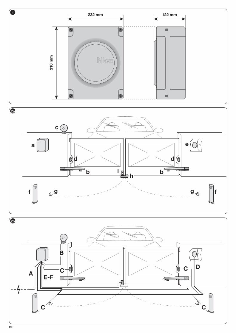
1232 mm
310 m
m
122 mm
XII
2a
d
i
g
b
f
d
h
g
b
ea
f
c
G
2b
B
A C
C C
C
E-F
D
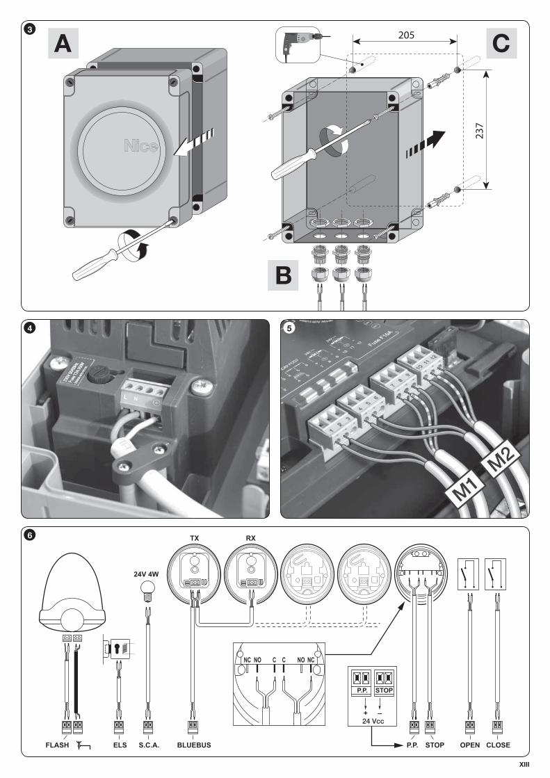
4 5
FLASH ELS S.C.A. OPEN CLOSEBLUEBUS
TX
24V 4W
RX
P.P.
NC NO C C NO NC
STOP
P.P. STOP
+ –24 Vcc
6
205
237
3
XIII
CA
B

10
9
XIV
87


![New - u.cdn.persiangig.comu.cdn.persiangig.com/preview/Dfwns6yxGi/Lets Go 1 Fourth Edition... · Of] Let's Remember Kate Andy Unit I Unit 2 3 Unit unit 5 Unit 6 Unit 7 Things for](https://static.fdocumenti.com/doc/165x107/5b77a5fb7f8b9a515a8d7a00/new-ucdn-go-1-fourth-edition-of-lets-remember-kate-andy-unit-i-unit.jpg)