
Control unit MC424
18
EN - Instructions and warnings for installation and use IT - Istruzioni ed avvertenze per l’installazione e l’uso FR - Instructions et avertissements pour l’installation et l’utilisation ES - Instrucciones y advertencias para la instalación y el uso DE - Installierungs-und Gebrauchsanleitungen und Hinweise PL - Instrukcje i ostrzeżenia do instalacji i użytkowania NL - Aanwijzingen en aanbevelingen voor installatie en gebruik Moon Control unit MC424
Transcript of Control unit MC424

EN - Instructions and warnings for installation and use
IT - Istruzioni ed avvertenze per l’installazione e l’uso
FR - Instructions et avertissements pour l’installation et l’utilisation
ES - Instrucciones y advertencias para la instalación y el uso
DE - Installierungs-und Gebrauchsanleitungen und Hinweise
PL - Instrukcje i ostrzeżenia do instalacji i użytkowania
NL - Aanwijzingen en aanbevelingen voor installatie en gebruik
MoonControl unit
MC424

EN
English – 1
ENGLISH
Safety warnings
• IMPORTANT! – This manual contains important instructions and warn-ings for personal safety. Incorrect installation could cause serious physicalinjury. Read all parts of the manual carefully before starting work. If in doubt,interrupt installation and contact the Nice Service Centre for clarifications.
• IMPORTANT! – Important instructions: keep this manual in a safe placeto enable future product maintenance and disposal procedures.
Installation warnings
• Before commencing installation, check that the product is suitable for theintended kind of use (see paragraph 2.2 “Limits of use” and chapter “Producttechnical specifications”). If not suitable, do NOT proceed with installation.
• During installation, handle the product with care, avoiding the risk of crushing,impact, dropping or contact with any type of liquid. Never place the productnear sources of heat or expose to naked flames. This may damage productcom ponents and cause malfunctions, fire or hazardous situations. If this oc -curs, suspend installation immediately and contact the Nice Service Centre.
• Never make modifications to any part of the product. Operations other thanas specified can only cause malfunctions. The manufacturer declines all liabil-ity for damage caused by makeshift modifications to the product.
• The product should not be used by children or people with impaired physical,sensorial or mental capacities or who have not received adequate training inthe safe use of the product.
• On the power line to the system, install a device for disconnection from thepower mains with a gap between contacts that assures complete disconnec-tion in the conditions of overvoltage category III.
• Connect the control unit to an electric power line equipped with an earthingsystem.
• The product’s packaging materials must be disposed of in full compliancewith local regulations.
GENERAL SAFETY WARNINGS AND PRECAUTIONS
The MC424 control unit has been designed to control Wingo 24 V electro-mechanical actuators, for automated swing gates or doors. IMPORTANT! –Any uses other than those specified herein or in environmental conditionsother than as stated in this manual are to be considered improper and arestrictly prohibited!
The MC424 control unit operates on the basis of a current sensitivity systemwhich checks the load of the motors connected to it. The system automaticallydetects travel stops, memorises the running time of each motor and recognis-es obstacles during normal movement. This feature makes installation easier asthere is no need to adjust the working times nor the leaf delay.
The control unit is pre-programmed for the normal functions, while more spe- cific functions can be chosen following a simple procedure (see chapter 5).
The control unit is designed to be powered by PS124 buffer batteries as emer-gency power supply in the event of a mains power failure (for further informationsee chapter 6.2). It is also designed to be connected to the “Solemyo” solarenergy system (for further information see chapter 6.3).
PRODUCT DESCRIPTION1
In order to explain certain terms and aspects of an automatic 2-leaf swing dooror gate system refer to the typical system shown in fig 1.
Key to fig. 1:
1.Wingo 24 V electromechanical actuator2.Electromechanical actuator3.Lucy24 flashing light4.Key-operated selector switch5. “PHOTO” pair of photocells6. “FOTO1” pair of photocells7. “PHOTO2” pair of photocells8. Control unit
In particular, please note that:
• Refer to the product instructions for the characteristics and connection of thephotocells.
• Activation of the “PHOTO” pair of photocells have no effect on the gate dur-ing opening, while they reverse movement during closing.
INSTALLATION2
SummaryGENERAL SAFETY WARNINGS AND PRECAUTIONS . . . . . . . . . 1
1 – PRODUCT DESCRIPTION . . . . . . . . . . . . . . . . . . . . . . . . . . . . . . . . 1
2 – INSTALLATION . . . . . . . . . . . . . . . . . . . . . . . . . . . . . . . . . . . . . . . . . . 1
2.1 - PRELIMINARY CHECKS FOR INSTALLATION . . . . . . . . . . . . . 2
2.2 - PRODUCT APPLICATION LIMITS . . . . . . . . . . . . . . . . . . . . . . . 2
2.3 - INSTALLATION . . . . . . . . . . . . . . . . . . . . . . . . . . . . . . . . . . . . . . 2
2.4 - ELECTRICAL CONNECTIONS . . . . . . . . . . . . . . . . . . . . . . . . . . 2
2.4.1 - Notes on connections . . . . . . . . . . . . . . . . . . . . . . . . . . . 3
2.4.2 - Type of ALT input . . . . . . . . . . . . . . . . . . . . . . . . . . . . . . . 3
2.4.3 - Examples of photocell connections: with the STANDBY
function active and the Phototest function disabled . . . 3
2.4.4 - Examples of photocell connections: with the Phototest .
function active and the STANDBY function disabled . . . 3
2.5 - INITIAL START-UP AND ELECTRICAL CONNECTIONS . . . . . . 3
2.6 - AUTOMATIC LIMIT SWITCH SEARCH . . . . . . . . . . . . . . . . . . . . 3
3 – TESTING AND COMMISSIONING . . . . . . . . . . . . . . . . . . . . . . . . . . 4
3.1 - TESTING . . . . . . . . . . . . . . . . . . . . . . . . . . . . . . . . . . . . . . . . . . . 4
3.2 - COMMISSIONING . . . . . . . . . . . . . . . . . . . . . . . . . . . . . . . . . . . . 4
4 – DIAGNOSTICS . . . . . . . . . . . . . . . . . . . . . . . . . . . . . . . . . . . . . . . . . . 4
5 – PROGRAMMING . . . . . . . . . . . . . . . . . . . . . . . . . . . . . . . . . . . . . . . . 4
5.1 - PRESET FUNCTIONS . . . . . . . . . . . . . . . . . . . . . . . . . . . . . . . . . 4
5.2 - PROGRAMMABLE FUNCTIONS . . . . . . . . . . . . . . . . . . . . . . . . 4
5.2.1 - Direct programming . . . . . . . . . . . . . . . . . . . . . . . . . . . . 4
5.2.2 - First level programming: first part . . . . . . . . . . . . . . . . . 4
5.2.3 - First level programming: second part . . . . . . . . . . . . . . 5
5.2.4 - Second level functions . . . . . . . . . . . . . . . . . . . . . . . . . . 5
5.3 - PROGRAMMING MODES . . . . . . . . . . . . . . . . . . . . . . . . . . . . . 5
5.3.1 - First level programming: functions . . . . . . . . . . . . . . . . . 6
5.3.2 - Second level programming: parameters . . . . . . . . . . . . 6
5.3.3 - Deletion of memory . . . . . . . . . . . . . . . . . . . . . . . . . . . . . 6
5.3.4 - Example of first level programming . . . . . . . . . . . . . . . . 7
5.3.5 - Example of second level programming . . . . . . . . . . . . . 7
5.3.6 - Programming diagrame . . . . . . . . . . . . . . . . . . . . . . . . . 8
6 – FURTHER DETAILS: accessories . . . . . . . . . . . . . . . . . . . . . . . . . . 9
6.1 - CONNECTING A RADIO RECEIVER . . . . . . . . . . . . . . . . . . . . . . 9
6.2 - CONNECTING MODEL PS124 BUFFER BATTERY . . . . . . . . . . 9
6.3 - CONNECTING THE SOLEMYO SYSTEM . . . . . . . . . . . . . . . . . . 9
7 – TROUBLESHOOTING (troubleshooting guide) . . . . . . . . . . . . . . . 9
8 – PRODUCT MAINTENANCE . . . . . . . . . . . . . . . . . . . . . . . . . . . . . . . 9
DISPOSAL OF THE PRODUCT . . . . . . . . . . . . . . . . . . . . . . . . . . . . 9
TECHNICAL CHARACTERISTICS OF THE PRODUCT . . . . . . . . 10
EC DECLARATION OF CONFORMITY . . . . . . . . . . . . . . . . . . . . . 10
RADIO RECEIVER: SMXI - SMIXS . . . . . . . . . . . . . . . . . . . . . . . . 11
1 - PRODUCT DESCRIPTION . . . . . . . . . . . . . . . . . . . . . . . . . . . . . . 11
2 - AERIAL INSTALLATION . . . . . . . . . . . . . . . . . . . . . . . . . . . . . . . . 11
3 - MEMORISING A REMOTE CONTROL . . . . . . . . . . . . . . . . . . . . 11
4 - DELETING ALL TRANSMITTERS . . . . . . . . . . . . . . . . . . . . . . . . 12
TECHNICAL CHARACTERISTICS OF THE PRODUCT . . . . . . . . . . 12
IMAGES . . . . . . . . . . . . . . . . . . . . . . . . . . . . . . . . . . . . . . . . . . . . . I - VII

EN
2 – English
Key to figs. 2 - 5a - 5b - 5c:
Terminals Function Description Type of cable
L - N - Power supply line Mains power supply 3 x 1,5 mm2
1÷3 Motor 1 M1 motor connection 3 x 1,5 mm2
1÷3 Motor 2 M2 motor connection (Note 1) 3 x 1,5 mm2
4÷5 Flashing light Connection of flashing light 24 V max 25 W 2 x 1 mm2
6÷7 Open Gate indicator / Connection for Open Gate Indicator 24 V max 5 W or Electric lock12 V SCA: 2 x 0,5 mm2
Elect.Lock max 25 VA (“See chapter 5 - Programming”) Electric lock: 2 x 1 mm2
8 Common 24 V Power Supply +24 V for TX photocells with phototest (max. 100 mA); “COMMON” 1 x 0,5 mm2
(with standby / phototest) for all inputs, safety, with STAND BY function activated (Note 2)
9 0 V Power supply 0V for services 1 x 0,5 mm2
10 24 V Power input for services, without “Standby” (24 V max 200 mA) 1 x 0,5 mm2
11 Common 24 V Common for all inputs (+24 V ) without “Standby” 1 x 0,5 mm2
12 STOP Input with STOP function (emergency, safety shutdown) (Note 3) 1 x 0,5 mm2
13 PHOTO NC Input for safety devices (photocells, sensitive edges) 1 x 0,5 mm2
14 PHOTO 1 NC Input for safety devices (photocells, sensitive edges) 1 x 0,5 mm2
15 STEP BY STEP Input for cyclical functioning (OPEN-STOP-CLOSE-STOP) 1 x 0,5 mm2
16 AUX Auxiliary input (Note 4) 1 x 0,5 mm2
17÷18 Aerial Connection for the radio receiver aerial screened cable type RG58
Note 1 – This is not used for single leaf gates (the control unit automatically recognises if only one motor has been installed).
Note 2 – The “Stand By” function serves to reduce consumptions. For further details on the electrical connections refer to paragraph 2.4.1 “Stand by/Phototestconnection” and for programming refer to chapter 5.2.3 “Stand by/Phototest function”.
Note 3 – The STOP input can be used for “NC” or constant resistance 8.2 kΩ contacts (please refer to the “Programming” chapter)
Note 4 – The AUX factory auxiliary input is programmed with the “Partial open type 1” function but can be programmed with any of the following functions:
Function Input type Description
PARTIAL OPEN TYPE 1 NO Fully opens the upper leaf
PARTIAL OPEN TYPE 2 NO Opens the two leaf half way
OPEN NO Only carries out the opening manoeuvre
CLOSE NO Only carries out the closing manoeuvre
• Activation of the “PHOTO 1” pair of photocells stops both the opening andclosing manoeuvres.
• Activation of the “PHOTO2” pair of photocells (connected to the suitably pro-grammed AUX input) has no effect during closing while they invert movementduring opening.
To check the parts of the control unit see fig. 2.
Key to fig. 2:
A. 24V power supply connectorB. M1 motor connectorC. PS124 buffer battery connector / Solemyo solar energy supply
system (for further details see chapter 6.3)D. 500mA F type services fuseE. Selector switch for delaying the opening of motor M1 or M2F. M2 motor terminalG. Flashing light output terminalH. Gate open indicator or electric lock output terminalI. 24Vdc terminals for services and phototestL. Input terminalsL1…L5. Input and programming LEDsM. Terminal for radio aerialN. “SM” radio receiver connectorO. Programming/diagnostics connectorP1, P2, P3. Programming buttons and LEDs
2.1 - Preliminary checks for installation
Before proceeding with installation, check the condition of the product compo-nents, suitability of the selected model and conditions of the intended installa-tion environment:• Ensure that all conditions of use remain within the limits of product applicationand within the “Product technical specifications”.• Ensure that the selected installation environment is compatible with the over-all dimensions of the product (fig. 3).• Ensure that the selected surfaces for product installation are solid and guar-antee a stable fixture.• Make sure that the fixing zone is not subject to flooding. If necessary, mountthe product raised from the ground.• Ensure that the space around the product enables easy and safe completionof manual manoeuvres.• Make sure that the automation is provided with mechanical stops on bothclosing and opening.
2.2 - Product application limits
The product may be used exclusively with Wingo 24 V gearmotors.
2.3 - Installation
To install the control unit, proceed as shown in fig. 4. Also observe the follow-ing warnings:
• The control unit is supplied in an enclosure that if correctly installed assures
an IP54 protection rating. The control unit is therefore suitable for installation
outdoors.
• Fix the control unit to a flat, vertical, non-removable surface that is adequate-
ly protected from potential impacts. Important! – The bottom of the control unit
must be at least 40 cm from the ground.
• Insert the dedicated cable clamps or pipe glands into the lower part of the
enclosure (fig. 4). Important! – If the cable protection tubes end in a pit, it is
likely that condensation will form inside the control unit, which will damage the
electronic board. In this case, protect the control unit adequately so as to pre-
vent the formation of condensation.
• The cable clamps can be inserted on the long side of the enclosure only if the
control unit is installed in a protected indoor environment.
To install the other devices present in the automation, refer to the relevant
instruction manuals.
2.4 - Electrical connections
IMPORTANT!
– All electrical connections must be made with the unit disconnected from
the mains power supply and with the buffer battery disconnected, if pres-
ent in the automation.
– Connections must be made exclusively by qualified personnel.
– Make sure that all the electric cables used are of a suitable type.
01. Loosen the screws of the cover.
02. Prepare the electrical cable routing holes.
03. Connect the cables as shown in the wiring diagram in fig. 5. To connect
the electric power cable, see fig. 6. Note – To facilitate cable connections,
the terminals can be removed from their seats.
• With the exception of the photocell inputs when the PHOTOTEST function is
activated, if the inputs of the NC (Normally Closed) contacts are not in use
they should be jumped with the “COMMON” terminal. Refer to paragraph
2.4.3 for further information.
• If there is more than one NC contact on the same input, they must be con-
nected in SERIES.
• If the inputs of the NO (Normally Open) contacts are not used they should be
left free.
• If there is more than one NO contact on the same input, they must be con-
nected in PARALLEL.
• The contacts must be electromechanical and potential-free. Stage connec-
tions, such as those defined as “PNP”, “NPN”, “Open Collector”, etc. are not
allowed.
• If the leafs overlap, use jumper E (Fig. 6) to select which motor starts up first
during opening.

EN
English – 3
PHOTO 2 NC PHOTO 2 function
DISABLED — No function
2.4.1 - Notes about connections
Most connections are extremely simple and many of them are direct connec-tions to a single user point or contact. The following figures show examples ofhow to connect external devices:
• Stand By / Phototest connection
The Stand-by function is active as standard. It is excluded automatically onlywhen the Phototest function is activated. Note - The Stand-by and Phototestfunctions are alternatives as one excludes the other.The Stand-by function allows consumptions to be reduced. Three types of con-
nections can be obtained:- with “stand by” active (energy saving); see electrical diagram in fig. 5a- standard connection: without “Stand by” and without “Phototest”; see electrical
diagram in fig. 5b- without “Stand by” and with “Phototest”; see electrical diagram in fig. 5c
When the “Stand-by” function is active, 1 minute after the end of a manoeuvrethe control unit goes into Stand-by, turning off the Inputs and Outputs toreduce consumptions. The status is indicated by the “OK” LED which begins toflash more slowly. WARNING – If the control unit is powered from a photovolta-ic panel (“Solemyo” system) or a buffer battery, the “Stand-by” function must beactivated as shown in the electrical diagram in fig. 5a.When the “Stand-by” function is not required, the “Phototest” function may beactivated. This verifies at the beginning of a manoeuvre that the connected pho-tocells operate correctly. To use this function, first connect the photocells appro-priately (see electrical diagram in fig. 5c) and then activate the function.
Note – When the phototest is activated, the inputs subjected to the test proce-dure are PHOTO, PHOTO1 and PHOTO2. If one of these inputs is not used itmust be connected to terminal no. 8.
• Key switch connection
Example 1 (fig. 7a): How to connect the switch in order to perform the STEP-BY-STEP and STOP functionsExample 2 (fig.7b): How to connect the switch in order to perform the STEP-BY-STEP and one of the auxiliary input functions (PARTIAL OPENING, OPENONLY, CLOSE ONLY …)
Note – For electrical connections with the “Stand By” function active, see“Stand By/Phototest function” in this paragraph 2.4.1.
• Connection for Gate Open Indicator / Electric lock (fig. 8)
If the gate open indicator has been programmed, the output can be used as anopen gate indicator light. The light, flashes slowly during opening and quicklyduring closing; If it is on but does not flash, this indicates that the gate is open.If the light is off, the gate is closed. Se the output has been programmed as anelectric lock, it is activated for 3 seconds each time opening begins.
2.4.2 - STOP type input
The MC424 control unit can be programmed for two types of STOP input:
- NC type STOP for connecting up to NC type contacts.- Constant resistance STOP. It enables the user to connect up to the control
unit of devices with 8.2kΩ constant resistance (e.g. sensitive edges). Theinput measures the value of the resistance and disables the manoeuvre whenthe resistance is outside the nominal value. Devices with normally open “NO”or normally closed “NC” contacts, or multiple devices, even of different types,can be connected to the constant resistance STOP input, provided thatappropriate adjustments are made; see Table 1.
WARNING! – If the constant resistance STOP input is used to connectdevices with safety functions, only the devices with 8.2 KΩ constant willresistance output guarantee the fail-safe category 3.
Notes to Table 1:
Note 1 – Any number of NO devices can be connected to each other in paral-lel, with an 8.2KΩ termination resistance (fig. 9a). For electrical connectionswith the “Stand By” function active, see “Stand By/Phototest function” in thisparagraph 2.4.1.
Note 2 – The NO and NC combination can be obtained by placing the two con-tacts in parallel, and placing an 8.2KΩ resistance in series with the NC contact.It is, therefore, possible to combine 3 devices: NO, NC and 8.2KΩ (fig. 9b).
Note 3 – Any number of NC devices can be connected in series to each otherand to an 8.2KΩ resistance (fig. 9c).
Note 4 – Only one device with an 8.2KΩ constant resistance output can beconnected; multiple devices must be connected “in cascade” with a single8.2KΩ termination resistance (fig. 9d).
2.5 - Initial start-up and electrical connections
IMPORTANT! – Connections must be made exclusively by qualified per-sonnel.
After powering up the control unit, check that all the LEDs flash rapidly for a fewseconds, then perform the following checks:
1. Check that there is a voltage of approximately 30Vdc on terminals 9-10. Ifnot, unplug the unit immediately and carefully check the connections andinput voltage.
2. After initially flashing rapidly, the P1 LED will indicate the control unit is work-ing correctly by flashing regularly at 1 second intervals. When there is a vari-ation in the inputs, the “P1” led will rapidly flash twice to show that the inputhas been recognised.
3. If the connections are correct, the LED for the “NC”-type inputs will be on,while those for the “NO” type inputs must be off. See fig. A and Table 2.
TABLE 2
INPUT INPUT TYPE STATUS LED
STOP STOP NC L1 On
CONSTANT RESISTANCE L1 OnSTOP 8.2 KΩ
PHOTO NC L2 On
FOTO1 NC L3 On
STEP-BY-STEP NO L4 Off
AUX OPEN PARTIALLY type 1 - NO L5 Off
OPEN PARTIALLY type 2 - NO L5 Off
OPEN ONLY - NO L5 Off
CLOSE ONLY - NO L5 Off
FOTO2 - NC L5 On
4.Check that the relative LEDs switch on and off when the devices connectedto the inputs are operated.
5.Check that by pressing P2 both motors perform a short opening manoeuvre,and the motor of the upper leaf starts first. Block the manoeuvre by press-ing P2 again. If the motors do not start up for opening, invert the polarities ofthe motor cables. If, however, the first one to move is not the upper leaf,operate jumper E (fig. 2).
2.6 - Automatic search system for the limit switches
On the successful completion of the various controls, start the automaticsearch system phase for the limit switches. This work is necessary as theMC424 control unit must “measure” how long the opening and closingmanoeuvres take This procedure is completely automatic and detects themechanical opening and closing stops by measuring the load on the motors.
Warning! – If this procedure has already been carried out, in order toreactivate it, the user must first delete the memory (see the “Memory de -letion” chapter). In order to check whether the memory contains any li mitswitch parameters, turn the power supply to the control unit on and thenoff again. If all the LEDs flash rapidly for approximately 6 seconds, theme mory is empty. If, however, they only flash for 3 seconds, the memoryalready contains some limit switch parameters.
Before starting limit switch searching, make sure that all the safety devices areenabled (STOP, PHOTO and PHOTO1). The procedure will be immediatelyinterrupted if a safety device triggers or a command arrives. Ideally the doorsshould be half open, although they can be in any position.
Procedure – Press the P2 button (fig. 2) to start begin searching whichincludes:
- Both motors open briefly.- Motor closes the lower leaf until it reaches the mechanical closing stop.- The upper leaf motor closes until it reaches the mechanical closing stop.- The motor of the upper leaf begins to open.- After the programmed delay, opening of the lower leaf begins. If the delay is
in sufficient, block the search by pressing P1 (fig. 2), then modify the time (seechapter 5).
- The control unit measures the movement required for the motors to reach theopening mechanical stops.
- Complete closing manoeuvre. The motors can start at different times, the aimis to prevent the leafs from shearing by maintaining a suitable delay.
- End of the procedure with memorisation of all measurements.
A
1st device type:
NO NC 8,2 KΩ
In parallel (note 1) (note 2) In parallel
NC (note 2) In series (note 3) In series
8,2KΩ In parallel In series (note 4)
TABLE 1
second
devi
ce t
ype:
EN
4 – English
All these phases must take place one after the other without any interferencefrom the operator. If the procedure does not continue correctly, it must be inter-rup ted with the P1 button. Repeat the procedure, modifying some parameters ifnecessary, for example the current sensitivity cut-in thresholds (see chapter 5).
These are the most important phases of automation set-up for ensuring maxi-
mum system safety. The test can also be performed as a periodic check of
automation devices. Testing and commissioning of the automation must be
performed by skilled and qualified personnel, who are responsible for the tests
required to verify the solutions adopted according to the risks present, and for
ensuring observance of all legal provisions, standards and regulations, and in
particular all requirements of the standard EN 12445, which establishes the test
methods for checking automations for doors and gates.
The additional or optional devices must undergo a specific test for functionality
and correct interaction with MC424. Refer to the instruction manuals of the
individual devices.
3.1 - Testing
The testing sequence refers to the control unit programmed with the preset
functions. See paragraph 5.1:
• Make sure that the activation of the STEP-BY-STEP input generates the fol-
lowing sequence of movements: “Open, Stop, Close, Stop”.
• Make sure that the activation of the AUX input (Type 1 partial opening function)
manages the “Open, Stop, Close, Stop” sequence of the motor of the upper
leaf only, while the motor of the lower leaf remains in the closed position.
• Perform an opening manoeuvre and check that:
- the gate continues the opening manoeuvre when PHOTO is engaged
- the opening manoeuvre stops when PHOTO1 is engaged and only continues
when PHOTO1 is disengaged
- The manoeuvre stops when PHOTO2 (if installed) is engaged and the closing
manoeuvre starts
• Make sure that the motor switches off when the door reaches the mechanical
stop.
• Perform an opening manoeuvre and check that:
- The manoeuvre stops when PHOTO is engaged and the opening manoeuvre
starts
- The manoeuvre stops when PHOTO1 is engaged and the opening manoeu-
vre starts again when PHOTO1 is disengaged
- the gate continues the closing manoeuvre when PHOTO 2 is engaged
• Check that the stopping devices connected to the STOP input immediately
stop all movement.
• Check that the level of the obstacle detection system is suitable for the appli-
cation:
- During both the opening and the closing manoeuvres, prevent the leaf from
moving by placing an obstacle and check that the manoeuvre inverts before
exceeding the force set down by law
• Other checks may be required depending on which devices are connected to
the inputs.
Warning – If an obstacle is detected as moving in the same direction for 2
consecutive manoeuvres in the same direction, the control unit partially
inverts both motors for just 1 second. At the following command, the leafs
begin the opening manoeuvre and the first current sensitivity cut-in for
each motor is considered as a mechanical stop during the opening cycle.
The same happens when the mains power supply is switched on: the first
command is always an opening manoeuvre and the first obstacle is
always considered as a mechanical stop during the opening cycle.
3.2 - Commissioning
Commissioning can only be performed after positive results of all test
phases.
1 Prepare the automation technical documentation, which must contain the
following documents: overall drawing of the automation, electrical wiring
diagram, risk assessment and relative solutions adopted (refer to the rele-
vant forms on our website www.niceforyou.com), manufacturer’s declara-
tion of conformity for all devices used and installer’s declaration of con-
formity.
2 Affix a dataplate on the gate, specifying at least the following data: type of
automation, name and address of manufacturer (responsible for commis-
sioning), serial number, year of construction and CE mark.
3 Before commissioning the automation, ensure that the owner is adequately
informed of all associated risks and hazards.
TESTING AND COMMISSIONING3
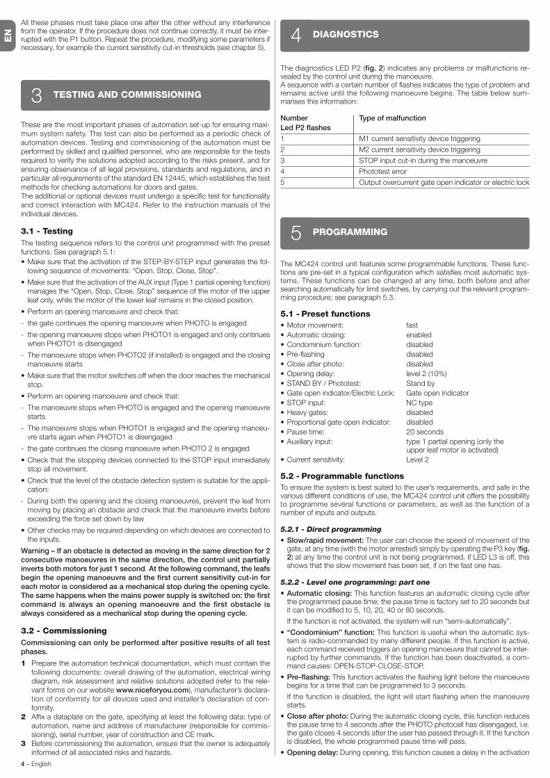
The diagnostics LED P2 (fig. 2) indicates any problems or malfunctions re -vealed by the control unit during the manoeuvre.A sequence with a certain number of flashes indicates the type of problem andremains active until the following manoeuvre begins. The table below sum-marises this information:
Number Type of malfunction
Led P2 flashes
1 M1 current sensitivity device triggering
2 M2 current sensitivity device triggering
3 STOP input cut-in during the manoeuvre
4 Phototest error
5 Output overcurrent gate open indicator or electric lock
DIAGNOSTICS4
The MC424 control unit features some programmable functions. These func-tions are pre-set in a typical configuration which satisfies most automatic sys-tems. These functions can be changed at any time, both before and aftersearching automatically for limit switches, by carrying out the relevant program-ming procedure; see paragraph 5.3.
5.1 - Preset functions
• Motor movement: fast
• Automatic closing: enabled
• Condominium function: disabled
• Pre-flashing disabled
• Close after photo: disabled
• Opening delay: level 2 (10%)
• STAND BY / Phototest: Stand by
• Gate open indicator/Electric Lock: Gate open indicator
• STOP input: NC type
• Heavy gates: disabled
• Proportional gate open indicator: disabled
• Pause time: 20 seconds
• Auxiliary input: type 1 partial opening (only theupper leaf motor is activated)
• Current sensitivity: Level 2
5.2 - Programmable functions
To ensure the system is best suited to the user’s requirements, and safe in thevarious different conditions of use, the MC424 control unit offers the possibilityto programme several functions or parameters, as well as the function of anumber of inputs and outputs.
5.2.1 - Direct programming
• Slow/rapid movement: The user can choose the speed of movement of thegate, at any time (with the motor arrested) simply by operating the P3 key (fig.2) at any time the control unit is not being programmed. If LED L3 is off, thisshows that the slow movement has been set, if on the fast one has.
5.2.2 - Level one programming: part one
• Automatic closing: This function features an automatic closing cycle afterthe programmed pause time; the pause time is factory set to 20 seconds butit can be modified to 5, 10, 20, 40 or 80 seconds.
If the function is not activated, the system will run “semi-automatically”.
• “Condominium” function: This function is useful when the automatic sys-tem is radio-commanded by many different people. If this function is active,each command received triggers an opening manoeuvre that cannot be inter-rupted by further commands. If the function has been deactivated, a com-mand causes: OPEN-STOP-CLOSE-STOP.
• Pre-flashing: This function activates the flashing light before the manoeuvrebegins for a time that can be programmed to 3 seconds.
If the function is disabled, the light will start flashing when the manoeuvrestarts.
• Close after photo: During the automatic closing cycle, this function reducesthe pause time to 4 seconds after the PHOTO photocell has disengaged, i.e.the gate closes 4 seconds after the user has passed through it. If the functionis disabled, the whole programmed pause time will pass.
• Opening delay: During opening, this function causes a delay in the activation
PROGRAMMING5

EN
English – 5
of the lower leaf motor compared with the upper one This is necessary inorder to prevent the leafs from getting stuck. There is always a standard delayduring closing, calculated automatically by the control unit in order to ensurethe same delay as the one programmed for opening.
5.2.3 - Level one programming: part two
• Stand By / Phototest function: The control unit has the “Stand-by” functionpreset. If this function is active, 1 minute after the end of a manoeuvre thecontrol unit turns off the “Stand-by” output (terminal no. 8) and all the Inputsand other Outputs to reduce consumptions (see electrical diagram in fig. 5a).This function is obligatory if the control unit is powered exclusively with Sole-myo photovoltaic panels. It is also recommended if the control panel is pow-ered from the electric mains and if you wish to extend emergency operationwith the buffer battery PS124. As an alternative to the “Stand-by” function,the “Phototest” function may be activated. This verifies at the beginning of amanoeuvre that the connected photocells operate correctly. To use this func-tion, connect the photocells correctly (see electrical diagram in fig. 5c) andthen activate the function.
• Open gate indicator light / electric lock: If the function is activated, termi-nals 6-7 can be used to connect up the electric lock. If the function is deacti-vated, terminals 6-7 can be used to connect up a 24V gate open indicator.
• NC Type or Constant Resistance STOP Input: If the function is activated,the STOP input is set to “8.2KΩ Constant Resistance”. In this case, theremust be a 8.2KΩ +/-25% resistance between the common and the input toenable the operation. If the function is not set, the configuration of the STOPinput will enable it to function with NC type contacts.
• Light/heavy gates : If the function is activated, the control unit enables theuser to manage heavy gates, setting the acceleration ramps and slowdownspeeds during closing differently. If the function is deactivated, the control unitwill be set to manage light gates.
• Proportional gate open indicator: If the function is activated, the gate openin dicator output will be set with the proportional flashing light. This means thatduring opening, the flashing becomes more intense as the leafs come nearerto the opening stops; vice-versa, for closing, the flashing becomes lessintense as the leafs come nearer to the closing stops. If the function is deacti-vated, the light will flash slowly during opening and rapidly during closing.
5.2.4 - Level two functions
• Pause time: The pause time, namely the time which lapses between openingand closing during automatic functioning, can be programmed to 5, 10, 20,40, and 80 seconds.
• Auxiliary input AUX: The control unit offers an auxiliary input which can beset to carry out one of the following 6 functions:
- Partial opening type 1: this carries out the same function as the STEP-BY-STEP input. It causes only the upper leaf to open. It only works if the gate isclosed completely, otherwise the command is interpreted as if it were aSTEP-BY-STEP comman.
- Partial opening type 2: this carries out the same function as the STEP-BY-STEP input. It causes the two leafs to open for half the time it would takethem to open completely. It only works if the gate is closed completely, other-wise the command is interpreted as if it were a STEP-BY-STEP command.
- Open only: this input only causes opening in the Open-Stop-Open-Stopsequence.
- Close only: this input only causes closing in the Open-Stop-Open-Stopsequence.
- Photo 2: this carries out the function of the “PHOTO 2” safety device.
- Disabled: the input will not carry out any function
• Discharge time: At the end of the Closing manoeuvre, after the leafs havereached the totally closed position, the motor continues to “push” the leaf fora brief interval, to ensure perfect closure. Immediately afterwards, this func-tion activates a very brief inversion of movement to reduce excessive pres-sure exerted by the motor on the leafs.
• Current sensitivity: The control unit is equipped with a system which meas-ures the current absorbed by the two motors used to detect the mechanicalstops and any obstacles when the gate is moving. Since the current ab -sorbed depends on a number of conditions, including the weight of the gate,friction, wind and variations in voltage, the cut-in threshold can be changed.There are 6 levels: 1 is the most sensitive (minimum force), 6 is the least sen-sitive (maximum force).
WARNING! – If the “current sensitivity” function (together with othervital features) is adjusted correctly, the system will comply with Euro-pean standards, EN 12453 and EN 12445, which require techniques ordevices to be used to limit force and danger during the functioning ofautomatic gates and doors are moved.
• Leaf delay: The delay in starting up the motor of the lower leaf can be pro-grammed to 5, 10, 20, 30 or 40% of the working time.
5.3 - Programming
All the functions described in paragraph 5.2 “Programmable functions” chaptercan be selected by means of a programming phase which terminates by mem-orising the choices made. The control unit therefore has a memory which storesthe functions and parameters relative to the automation process.
The P1, P2 and P3 buttons are used for all the programming phases, while the5 LEDs (L1, L2…L5) indicate the selected parameter.
There are two different programming levels:
• At level 1, the functions can be enabled or disabled. Each Led (L1, L2…L5)corresponds to a function: if the Led is on, the function is active; if it is off, it isdeactivated.
Level one consists in 2 parts which can be selected using the P3 button. Thecor responding LED P3 indicates which of the 2 parts has been selected.
Level one (P1 Led lit): part two (P3 Led lit)
L1 Led L2 Led L3 Led L4 Led L5 Led
Stand By / Electric lock Resistance Heavy gates Gate open
Phototest stop proportional
Level one (P1 Led lit): part one ( P3 Led off)
L1 Led L2 Led L3 Led L4 Led L5 Led
Closing Function Pre-flash Close after Delay in
Automatic Condominium photo opening
• It is possible to pass to the second level from level one of part one. At thissecond level the user can choose the parameter relating to the function. Adifferent value corresponds to each LED which must be associated to theparameter.
Level one (P1 Led lit): part two (P3 Led lit)
L1 Led L2 Led L3 Led L4 Led L5 Led
Stand By / Electric lock Resistance Heavy gates Gate open
Phototest stop proportional
Level one (P1 Led lit): part one (led P3 off)
L1 Led L2 Led L3 Led L4 Led L5 Led
Closing Function Pre-flashing Close after Delay in
automatic condominium photo opening
Level two:
Parameter: Parameter: Parameter: Parameter: Parameter:
Time AUX input Time Current Leaf delay
pause discharge sensitivity
L1: 5s L1: Open L1: no L1: Level 1 L1: 5%s
partial TYPE 1 discharge (more sensitive)
L2: 10s L2: Open L2: 0.3s L2: Level 2 L2: 10%
partial TYPE 2
L3: 20s L3: Open Only L3: 0.7s L3: Level 3 L3: 20%
L4: 40s L4: Close Only L4: 1.3s L4: Level 4 L4: 30%
L5: 80s L5: Photo 2 L5: 2s L5: Level 5 L5: 40%
(less sensitive)
All LEDs off: All LEDs off:
input Level 6
not used (max current
sensitività )

EN
6 – English
TABLE A1 - Entering level one programming
01. Press and hold down buttons P1 and P2 for at least 3 secondsThe programming mode has been entered if all the Leds start flashing quickly
TABLE A2 - Activating or deactivating a function
01. Press P1 repeatedly until the flashing Led reaches the function required
02. Press P1 repeatedly until the flashing Led reaches the function required
TABLE A3 - To pass from part one to part two of level one (and vice-versa)
01. Press P3. button
TABLE A4 - To exit level one and save the modifications
01. Press P1 and then immediately P2, holding them both down for at least 3 seconds
TABLE A5 - Exiting level one and delete the modifications
01. Either press P1 for at least 3 seconds, or wait for 1 minute, or disconnect the power supply
5.3.1 - Level one programming: functions
At level 1, the functions can be enabled or disabled. At level one, LED P1 isalways on; if LEDs L1, L2…L5 are on, the functions are activated; if the LEDsare off, the functions are deactivated. A flashing LED indicates which function
has been selected, short flashes indicate the function has been deactivated;long flashes indicate the function has been activated. Press P3 to pass frompart one programming to part two programming, and vice-versa.
P1 P2
P1
P2
P3
P1 P2
3s or 60s
or
P1
5.3.2 - Level two programming: parameters
The function parameter can be chosen at level two. Level two can only be
reached from level one. At level 2 the P1 Led flashes quickly while the 5 Leds
(L1, L2…L5) indicate the selected parameter.
TABLE B1 - Entering level two programming
01. Enter level one programming by pressing P1 and P2 for at least 3 seconds
02. Select the function by pressing P1 until the flashing Led reaches the point required
03. Enter level two by pressing the P2 button for at least 3 seconds
TABLE B2 - Selecting the parameter
01. Press P2 repeatedly until the Led reaches the desired parameter
TABLE B3 - Returning to level one
01. Press P1
TABLE B4 - Exiting level one and saving modifications
01. Press P1 and then immediately P2, holding them both down for at least 3 seconds
TABLE B5 - Exiting level one and cancelling modifications
01. Either press P1 for at least 3 seconds, or wait for 1 minute, or disconnect the power supply
3 sP1 P2
P1 P2
3s or 60s
or
P1
P1
P2
P1
P2 3 s
5.3.3 - Memory deletion
Each new programme replaces the previous settings. It is usually unnecessaryto “delete all” the parameters”. If required, the memory can be totally deleted by
performing this simple operation: WARNING – As all the functions return to
their pre-set values after the memory is deleted, a new search for the lim-
it switches must be carried out.
3 s
EN
English – 7
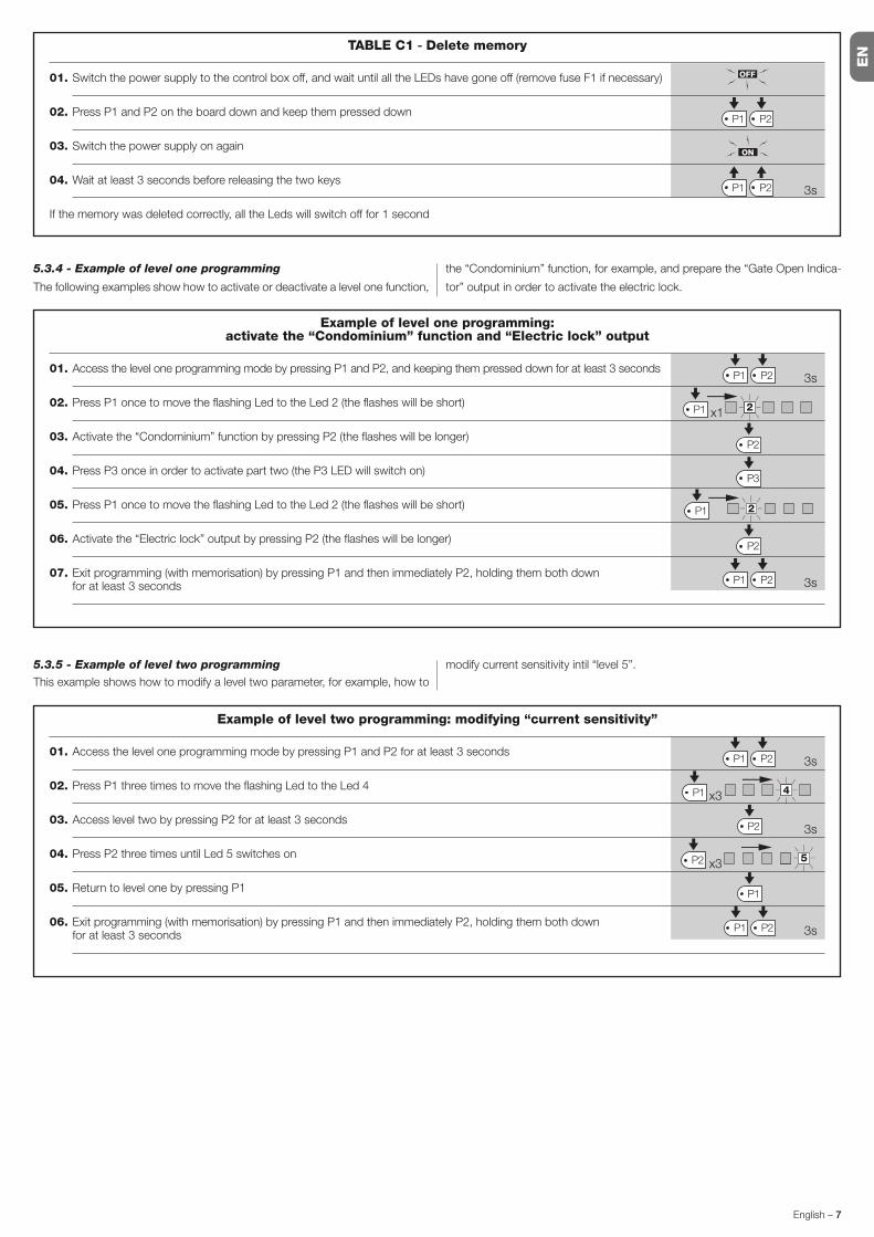
TABLE C1 - Delete memory
01. Switch the power supply to the control box off, and wait until all the LEDs have gone off (remove fuse F1 if necessary)
02. Press P1 and P2 on the board down and keep them pressed down
03. Switch the power supply on again
04. Wait at least 3 seconds before releasing the two keys
If the memory was deleted correctly, all the Leds will switch off for 1 second
3s
P1 P2
P1 P2
5.3.4 - Example of level one programming
The following examples show how to activate or deactivate a level one function,
the “Condominium” function, for example, and prepare the “Gate Open Indica-
tor” output in order to activate the electric lock.
Example of level one programming:activate the “Condominium” function and “Electric lock” output
01. Access the level one programming mode by pressing P1 and P2, and keeping them pressed down for at least 3 seconds
02. Press P1 once to move the flashing Led to the Led 2 (the flashes will be short)
03. Activate the “Condominium” function by pressing P2 (the flashes will be longer)
04. Press P3 once in order to activate part two (the P3 LED will switch on)
05. Press P1 once to move the flashing Led to the Led 2 (the flashes will be short)
06. Activate the “Electric lock” output by pressing P2 (the flashes will be longer)
07. Exit programming (with memorisation) by pressing P1 and then immediately P2, holding them both down for at least 3 seconds
P1 P2
2P1
P2
P3
P2
P1 P2
2P1
3s
3s
x1
Example of level two programming: modifying “current sensitivity”
01. Access the level one programming mode by pressing P1 and P2 for at least 3 seconds
02. Press P1 three times to move the flashing Led to the Led 4
03. Access level two by pressing P2 for at least 3 seconds
04. Press P2 three times until Led 5 switches on
05. Return to level one by pressing P1
06. Exit programming (with memorisation) by pressing P1 and then immediately P2, holding them both down for at least 3 seconds
P1 P2
3s
3s
3s
4P1
5P2
P2
P1
P1 P2
x3
x3
5.3.5 - Example of level two programming
This example shows how to modify a level two parameter, for example, how to
modify current sensitivity intil “level 5”.

EN
8 – English
5.3.6 - Programming diagram
The following figure shows the complete programming diagram of the functionsand relative parameters.
This figure also shows the functions and parameters either as they were initiallyor following total memory deletion.
ALT Photo Photo
1
Step
by
step
AUX
Normal operation
Led P1 Slow flashing
Level oneLed P1 On permanently
Level twoLed P1 Rapid flashing type 1
p.o
type 2
p.o
only
opening
only
closing
Photo 2
All Leds off · max. current sensitivity
P1+P2
for 3 secs
P1
for 3 secs
(NO SAVE)
P1+P2
for 3 secs
(SAVE)
Autom.
closing
Cond. Pre-
flashing
Close
after
Photo
Opening
delayOnOff
OnOff
AUXILIARY INPUT (*)
DISCHARGE
CURRENT SENSITIVITY
1 2 3
Level
4 5
OPENING DELAY
5 10 20
%
30 40
5 10 20
seconds
40 80
PAUSE TIME
P1P2
for 3 secs
P1
P1
P2
P3
P1
P2
P3
P1
P2
P3
P1
P2
P3
P1
P2
P3
P1
P2
P3
P2
P3
Stand
by /
Phototest
Electric
Lock
Resist.
STOP.
Heavy
gates
Proportional
Gate
Open
P3
P1
P2
P3
0 0,3 0,7
seconds
1,3 2
(*)
a.p. type 1 type 1 partial open, upper leaf
moves [N.O.]
a.p. type 2 type 2 partial opening, both
motors move for 1/2 the working
time set [N.O.]
Only open open � stop � open � stop…
[N.O.]
Only closed close � stop � close � stop…
[N.O.]
Photo 2 used as photo 2 [N.C.]

EN
English – 9
6.1 - Connecting a radio receiver
The control unit has a connector for fitting a 4 channel radio card complete withSM slot. This remote control device functions by means of transmitters whichact on the inputs as per the following table:
Output Receiver Control unit inputN° 1 Step by stepN° 2 AUX (reset value: Partially Open 1)N° 3 “Open only”N° 4 “Close only”
6.2 - Connecting model PS124 buffer battery
PS124 buffer batteries can be used to supply the control unit in case of net-work blackouts. To install and connect the battery, proceed as shown in fig. 10.
6.3 - Connecting the Solemyo system
The control unit is designed to be powered with the “Solemyo” photovoltaicsystem (photovoltaic panel and 24 V battery). To connect the Solemyo batteryto the control unit, use the socket on the control unit that is normally used forthe buffer battery (see paragraph 6.2).
IMPORTANT!- When the automation is powered by the “Solemyo” system, it MUSTNOT BE POWERED at the same time from the electrical mains.- The Solemyo system can be used only if the Standby function on the con- trol unit is ON and the connections are as shown in the diagram in fig. 5a.
FURTHER DETAILS: accessories6
No LEDs are on:
• Check whether the control unit is powered (measure a voltage of about30Vdc at terminals 9-10 (or 24 Vdc with battery power).
• Check the 2 fuses, if not even the P1 Led is on or flashing a serious fault hasprobably occurred and the control unit must therefore be replaced.
The P1 LED flashes regularly but the input LED’s L1, L2...L5 do not reflectthe state of the respective inputs
• Switch the unit off for the moment in order to exit a possible programmingphase.
• Carefully check the connections on terminals 11 to 16.
LED P1 flashes every 4 seconds
• The control unit is in Stand by status.
The “Automatic search” procedure does not start up
• The “Automatic search” procedure only starts if it has never been performedbefore or if the memory has been deleted. To check whether the memory isempty switch off the unit for a moment. When it is switched on again, all theLeds should flash rapidly for about 6 seconds. If they only flash for 3 sec-onds, the memory already contains valid values. If a new “Automatic search”is required, the memory must be completely deleted.
The “Automatic search” procedure has never been performed but it eitherdoes not start or it behaves incorrectly
• The system and all the safety devices must be operative in order to activatethe “Automatic search” procedure.
• Make sure that no device connected to the inputs cuts in during the “Auto-matic search” procedure.
• In order for the “Automatic search” procedure to start correctly, the inputLeds must be on as shown in fig. 11, the P1 Led must flash once a second.
The “Automatic search” procedure was performed correctly but themanoeuvre does not start
• Check that the safety device (STOP, PHOTO, PHOTO1 and, if installed,PHOTO2) Leds are on and that the relative command Led (STEP-BY-STEPor AUX) remains on for the entire duration of the command.
• If the “Phototest” function is activated but the photocells do not function cor-rectly, the DIAGNOSTICS LED indicates the fault by flashing four times.
The gate inverts the direction while moving
An inversion is caused by:• The photocells triggering (PHOTO2 during the opening manoeuvre, PHOTO
or PHOTO1 during the closing manoeuvre). In this case, check the photocellconnections and input LEDs.
• The current sensitivity device triggers while the motors are moving (not near
TROUBLESHOOTING(troubleshooting guide)7
the mechanical stops, therefore). This is considered as an obstacle andcauses an inversion. To find out if the current sensitivity device has triggered,count how many times the Diagnostics LED flashes: 1 flash indicates that thecurrent sensitivity device triggered on account of motor 1, 2 flashes indicatethat this was caused by motor 2.
PRODUCT MAINTENANCE8As the MC424 control unit is electronic it requires no particular maintenance.However, at least every six months the efficiency of the entire system must bechecked according to the information described in chapter 3.
DISPOSAL OF THE PRODUCT
This product is an integral part of the automation, and therefore, theymust be disposed of together.
As for the installation operations, at the end of the life of this product, the dis-mantling operations must be performed by qualified personnel.
This product is made from different types of materials: some can be recycled,others must be disposed of. Please inform yourselves on the recycling or dis-posal systems provided for by the laws in force in your area, for this category ofproduct.
CAUTION! – some parts of the product can contain polluting or dangeroussubstances which, if dispersed in the environment, may cause serious harm tothe environment and human health.
As indicated by the symbol at the side, it is forbidden tothrow this product into domestic refuse. Therefore, follow the“separated collection” instructions for disposal, according tothe methods provided for by local regulations in force, orredeliver the product to the retailer at the moment of pur-chase of a new, equivalent product.
CAUTION! – the regulations in force at local level may envisage heavy sanc-tions in case of abusive disposal of this product.

EN
10 – English
EC DECLARATION OF CONFORMITY
Note - The contents of this declaration correspond to declarations in the last revision of the official document deposited at the registered offices of Nice Spa available before thismanual was printed. The text herein has been re-edited for editorial purposes.
Number: 296/MC424 Revision: 0
The undersigned, Lauro Buoro, in the role of Managing Director, declares under his sole responsibility, that the product:
Manufacturer’s Name: NICE s.p.a.Address: Via Pezza Alta 13, Z.I. Rustignè, 31046 Oderzo (TV) ItalyType: Two 24 Vdc motor control unitModels: MC424Accessories: SMXI, SMXIS radio receiver
conform with the requirements of the following EC directives:
• 98/37/EC (89/392/EEC amended); DIRECTIVE 98/37/EC OF THE EUROPEAN PARLIAMENT AND COUNCIL of 22 June 1998 regarding the approxima-tion of member state legislation relating to machinery.As established in directive 98/37/EC, the above-mentioned product may not be started up unless the machine in which the product is incorporated hasbeen identified and declared as conforming to directive 98/37/EC.
The product also complies with the requirements of the following EC directives:
• 2006/95/EEC (ex directive 73/23/EEC); DIRECTIVE 2006/95/EEC OF THE EUROPEAN PARLIAMENT AND COUNCIL of 12 December 2006 regardingthe approximation of member state legislation relating to electrical material intended for use within specific voltage limitsAccording to the following harmonised standards: EN 60335-1:1994+A11:1995+A1:1996+A12:1996+A13:1998+A14:1998+A15:2000+A2:2000+A16:2001
• 2004/108/EEC (ex directive 89/336/EEC); DIRECTIVE 2004/108/EEC OF THE EUROPEAN PARLIAMENT AND COUNCIL of 15 December 2004 regard-ing the approximation of member state legislation relating to electromagnetic compatibility, repealing directive 89/336/EECAccording to the following harmonised standards: EN 61000-6-2:2001; EN 61000-6-3:2001+A11:2004
The product also complies, within the constraints of applicable parts, with the following standards:EN 60335-1:2002+A1:2004+A11:2004+A12:2006+ A2:2006, EN 60335-2-103:2003, EN 13241-1:2003; EN 12453:2002; EN 12445:2002;EN 12978:2003
Oderzo, 25 September 2008 Lauro Buoro (Managing Director)
WARNINGS: • All technical characteristics stated refer to an ambient temperature of 20°C (±5°C). • Nice S.p.a reserves the right to modify the product at anytimee, while maintaining the same functionalities and intended use.
Mains power supply MC424 Control units: 230 V~ ±10% 50 ÷ 60 HzMC424/V1 Control units: 120 V~ ±10% 50 ÷ 60 Hz
Max absorbed power 170 W
Emergency power supply for PS124 buffer batteries and for Solemyo solar kit
Maximum motor current: 3A (with a “level 6” current sensitivity cut in)
Service power output 24 V 200 mA maximum current (the voltage can vary from 16 to 33 V )
Phototest Output 24 V 100 mA maximum current (the voltage can vary from 16 to 33 V )
Flashing lamp output for flashing lamp 24 V , maximum power 25 W (the voltage can vary from 16 to 33 V )
Gate open indicator output for indicator lamps at 24 V maximum power 5 W (the voltage can vary from 16 to 33V )or electric locks 12 V~ 25 W
STOP Input for NC contacts or constant resistance 8,2 KΩ +/- 25%
Working time automatic detection
Pause time programmable at 5, 10, 20, 40, 80 seconds
Discharge time programmable to 0, 0.3, 0.7, 1.3, 2 seconds
Leaf delay in open cycle programmable at 5, 10, 20, 30 and 40 % of working time
Leaf delay in close cycle automatic detection
1st motor output for Wingo WG4024 - WG5024
2nd motor output for Wingo WG4024 - WG5024
Max. cable length 230 V power supply 30 m
Solemyo solar power kit 3 m
motors 10 m
other inputs/outputs 30 m
flashing light 10 m
SCA 30 m
electric lock 10 m
aerial 20 m (recommended less than 3 m)
Radio receiver “SM” type coupling for receivers SMXI, SMXIS, OXI (Mode I and Mode II)
Temperatura di esercizio from - 20 to 50 °C
Protection rating IP 54 with enclosure intact
Dimensions (mm) 310 x 232 x H 122
Weight (kg) 4,1
TECHNICAL CHARACTERISTICS OF THE PRODUCT

EN
English – 11
smxi - smixs radio receiver0682
SMXI and SMXIS are 4-channel radio receivers for control units equipped with
SM-type connector. The peculiarity of compatible transmitters is that the identi-
fication code is different for each transmitter. Therefore, in order to allow the
receiver to recognise a determined transmitter, the recognition code must be
memorised. This operation must repeated for each transmitter required to com-
municate with the control unit.
Notes:
– Up to a maximum of 256 transmitters can be memorised in the receiver. No
one transmitter can be cancelled; all the codes must be deleted
– For more advanced functions use the appropriate programming unit.
PRODUCT DESCRIPTION1The receiver features 4 outputs, all available on the underlying connector. Tofind out which function is performed by each output, see chapter 6.1.
During the transmitter code memorisation phase, one of these two options maybe chosen:
Mode I - Table B1: Each transmitter button activates the corresponding out-put in the receiver, that is, button 1 activates output 1, button 2 activates output2, and so on. In this case there is a single memorisation phase for each trans-mitter; during this phase, it doesn’t matter which button is pressed and just onememory sector is occupied.
Mode II - Table B2: Each transmitter button can be associated with a partic-ular output in the receiver, e.g., button 1 activates output 2, button 2 activatesoutput 1, and so on. In this case, the transmitter must be memorised, pressingthe required button, for each output to activate. Naturally, each button can acti-vate just one output while the same output can be activated by more than onebutton. One memory section is occupied for each button.
TABLE B1 - Mode I memorising (All buttons are memorised on the related receiver output)
01. Press and hold down the receiver button for at least 3 seconds
02. Release the button when the Led lights up
03. Push, for at least 2 seconds, any of the buttons of the transmitter to be memorised within 10 seconds
Note – If the procedure was memorised correctly, the Led on the receiver will flash 3 times. If there are other transmittersto memorise, repeat step 3 within another 10 seconds. The memorisation phase finishes if no new codes are receivedfor 10 seconds.
3sRX
TX
RX
2s
x3
INSTALLING THE AERIAL2
The receiver requires an ABF or ABFKIT type aerial to work properly; without anaerial the range is limited to just a few metres. The aerial must be installed ashigh as possible; if there are metal or reinforced concrete structures nearby youcan install the aerial on top. If the cable supplied with the aerial is too short, usea coaxial cable with 50-Ohm impedance (e.g. low dispersion RG58), the cablemust be no longer than 10 m.If the aerial is installed in a place that is not connected to earth (masonry struc-tures), the braid’s terminal can be earthed to provide a larger range of action.The earth point must, of course, be local and of good quality. If an ABF orABFKIT aerial cannot be installed, you can get quite good results using thelength of wire supplied with the receiver as the aerial, laying it flat.
WARNING – When the memorisation phase is activated, any tran s-mitter correctly recognised within the reception range of the radiois memorised. Consider this aspect with care and remove the aeri-al if necessary to reduce the capacity of the receiver.
MEMORISING A REMOTE CONTROL3
The procedures for memorising the remote controls must be performed withina certain time limit; please read and understand the whole procedure beforestarting.In order to carry out the following procedure, it is necessary to use the buttonlocated on the box of the radio receiver (reference A, Fig. 1a), and the corre-sponding LED (reference B, Fig. 1a) to the left of the button.
1a
TABLE B2 - Mode II memorising (A specific receiver output can be associated to each button)
01. Press and release the receiver button as many times as the number of the desired output (Once for output No. 1,twice for output No. 2)
02. Check that the LED emits the same number of flashes as the desired output, repeated over 10 seconds in regularintervals (1 flash if output No. 1, 2 flashes if output No. 2)
03. Within 10 seconds press the desired button on the transmitter to be memorised, holding it down for at least 2 seconds.
Note – If the procedure was memorised correctly, the Led on the receiver will flash 3 times. If there are other transmittersto memorise, repeat step 3 within another 10 seconds. The memorisation phase finishes if no new codes are receivedfor 10 seconds.
2s
x3
RX
TX

EN
12 – English
Remote memorising
It is possible to enter a new transmitter in the receiver memory without usingthe keypad. A previously memorised and operational remote control must beavailable. The new transmitter will “inherit” the characteristics of the previouslymemorised one. Therefore, if the first transmitter is memorised in mode I, thenew one will also be memorised in mode I and any of the buttons of the trans-mitter can be pressed. If the first transmitter is memorised in mode II the newone will also be memorised in mode II but the button activating the required
output must be pressed on the first transmitter as must the button required to
be memorised on the second. You need to read all the instructions in advance
so you can perform the operations in sequence without interruptions. Now, with
the two remote controls (the NEW one requiring code memorisation and the
OLD one that is already memorised), position yourself within the operating
range of the radio controls (within maximum range) and carry out the instruc-
tions listed in the table.
All the memorised codes can be deleted as follows:
DELETING ALL TRANSMITTERS4
TECHNICAL CHARACTERISTICS OF THE PRODUCT
Receivers: SMXI SMXIS
Decoding Rolling code 52 bit FLOR Rolling code 64 bit SMILO
Transmitter compatibility FLOR, VERY VR, NICE WAY, ERGO, PLANO, NICE ONE SMILO
Frequency 433.92 MHz 433.92 MHz
Input impedance 52 KΩ 52 KΩ
Outputs 4 (on SM connector) 4 (on SM connector)
Sensitivity better than 0.5 µV better than 0.5 µV
Working temp. from -10°C to + 55° C from -10°C to + 55° C
Transmitters: FLO2R SMILO
Buttons 1, 2 or 4 according to the versions 2 or 4
Power input 12 V Batt. 23 A 12 V Batt. 23 A
Absorption 10 mA 25 mA
Transmission frequency 433.92 MHz 433.92 MHz
Working temp. from -10°C to + 55° C from -10°C to + 55° C
Radiated power estimated approximately 1 mW E.R.P. estimated approximately 1 mW E.R.P.
Range estimated 200 m (outdoors); 35 m (indoors) estimated 200 m (outdoors); 35 m (indoors)
Dimensions / Weight 69 x 39 x 15,5 mm / 31 g. Ø 48 mm x H 14 mm - 14 g
Encoding digital (4.5 x10¹⁵ combinations) digital (18 x 1015 combinations)
WARNINGS: • All technical characteristics stated refer to an ambient temperature of 20°C (±5°C). • Nice S.p.a reserves the right to modify the product at anytimee, while maintaining the same functionalities and intended use. • The range of the transmitters and the reception capacity of the receivers may be subject tointerference that may alter their performance. In the event of interference, Nice cannot guarantee the effective capacity of their devices.
TABLE B3 - Remote Memorising
01. Press the button on the NEW transmitter for at least 5 seconds and then release
02. Press the button on the OLD transmitter 3 times slowly
03. Press the button on the NEW transmitter slowly and then release
Note – If there are other transmitters to memorise, repeat the above steps for each new transmitter.
1s
x1
TX
TX TX TX
TX
TX
1s1s
x5s
TABLE B4 - Deleting all transmitters
01. Press the receiver button and hold it down
02. Wait for the Led to light up, then wait for it to switch off and then wait for it to flash 3 times
03. Release the button exactly during the third flash
Note – if the procedure was performed correctly, the Led will flash 5 times after a few moments.
RX
RX
x3
3°
x5

II
M2
M1
L
N
D
C
A
FE G H I L M
4 5 6 8 9 10 11 12 13 14 15 1671 2 3
12
3B
P1
L1...L5
P2
P3
O
N
2
1 2
3
4
55
7
7
8
6 6
1
EN - E = Electric jumper
IT - E = Ponticello elettrico
FR - E = Cavalier électrique
ES - E = Conexión eléctrico
DE - E = Brücke
PL - E = Mostek elektryczny
NL - E = Elektrische
geleidingsbrug

III
3
205
237
4
232 mm
310 m
m
122 mm
TX RX
PHOTO2
5a
EN- Connection with “Stand by” active (energy saving)
IT - Collegamento con “Stand by” attivo (risparmio energetico)
FR- Connexion avec « stand-by » actif (économie d’énergie)
ES- Conexión con “Stand by” activo (ahorro energético)
DE- Anschluss mit aktivem “Standby” (Energieeinsparung)”
PL - Połączenie z aktywną funkcją “Stand by” (oszczędność energii)
NL- Aansluiting met “Stand by” actief (energiebesparing)

IV
6
TX RX 5c
EN- Connection without “Stand by” with “Phototest”
IT - Collegamento senza “Stand by” con “Fototest”
FR- Connexion sans « stand-by » et avec « phototest »
ES- Conexión sin “Stand by” con “Fototest”
DE- Ohne “Standby” und ohne “Phototest”
PL - Połączenie bez funkcji “Stand by” i z funkcją “Fototest”
NL- Aansluiting zonder “Stand by” met “Fototest”
TX RX 5b
EN- Standard connection: without using Standby or Phototest
IT - Collegamento standard: senza utilizzare “Stand by” e senza “Fototest”
FR- Connexion standard : sans utiliser « Stand by » et sans « Phototest »
ES- Conexión estándar: sin utilizar “Stand by” y sin “Fototest”
DE- Standardanschluss: ohne Nutzung des “Stand by” und ohne “Fototest”
PL - Połączenie standard: bez wykorzystywania funkcji “Stand by”
i bez “Fototestu”
NL- Standaard aansluiting: zonder gebruik van “Stand by”
en zonder "Fototest”

V
6
6
7
7
8
33 V
max 5 W
12 V~
max 25 VA
11
12
8,2K�NCNC
NA
NC11
12
8,2K�
NANA
11
12
8,2K�
9a
7a
ALT
NC NO C C NO NC
15
11
11
12
STEP BY STEP
7b
AUX
NC NO C C NO NC
15
11
11
16
STEP BY STEP
11
12
1 2 n 8,2K�9d
EN- With Stand by active connect terminal no. 8 and not no. 11
IT - Con Stand by attiva collegare il morsetto n° 8 e non il n° 11
FR- Avec Stand-by actif connecter la borne n° 8 et pas la n° 11
ES- Con “Stand by” activo, conecte el borne n° 8 y no el n° 11
DE- Bei aktivem Standby, die Klemme Nr. 8 und und nicht 11 anschließen
PL - Z aktywną funkcją Stand by należy połączyć zacisk nr 8 a nie nr 11
NL- Met actieve Stand by sluit u klem 8 aan en niet klem 11
EN- For the ALT connection with “Stand by” active, connect terminal
no. 8 and not no. 11
IT - Per il collegamento ALT, con “stand by” attiva, collegare il
morsetto n° 8 e non il n° 11
FR- Pour la connexion HALTE, avec « stand-by » actif, connecter la
borne n° 8 et pas la n° 11
ES- Para la conexión ALT, con “stand by” activo, conecte el borne n°
8 y no el n° 11
DE- Für den Anschluss STOPP, bei aktivem Standby, die Klemme Nr.
8 und nicht 11 anschließen
PL - Aby wykonać połączenie STOP z aktywną funkcją “stand by”
należy połączyć zacisk nr 8 a nie nr 11
NL- Voor de aansluiting ALT, met actieve “stand by”, sluit u de klem
8 aan en niet de klem 11
IT - Bordo sensibile
FR - Bord sensible
ES - Banda sensible
DE - Schaltleiste
PL - Listwa optyczna
NL - Contactlijst
Sensitive edge
IT - Bordo sensibile
FR - Bord sensible
ES - Banda sensible
DE - Schaltleiste
PL - Listwa optyczna
NL - Contactlijst
Sensitive edge
IT - Bordo sensibile
FR - Bord sensible
ES - Banda sensible
DE - Schaltleiste
PL - Listwa optyczna
NL - Contactlijst
Sensitive edge
9b 9c

VI
1110