COMUNE DI ANDRIA (BT)pdf.infobat.it/public/SettoreAmbientePrivato/Verifica Assog VIA/147... ·...
27
CENTRALE DI PRODUZIONE DI ENERGIA ELETTRICA DA FONTE EOLICA COMUNE DI ANDRIA (BT) GENERAL SPECIFICATION SIEMENS SWT-2.3-101 REV. 0 Pagina 1 CENTRALE DI PRODUZIONE DI ENERGIA ELETTRICA DA FONTE EOLICA COMUNE DI ANDRIA (BT) ALLEGATO 7A GENERAL SPECIFICATION SIEMENS SWT-2.3-101 Rev.n° Data Pag. n° Descrizione modifica Compilato Controllato Approvato 0 Nov. 10 M. Rubino F.Sergi V.Cavallo
Transcript of COMUNE DI ANDRIA (BT)pdf.infobat.it/public/SettoreAmbientePrivato/Verifica Assog VIA/147... ·...

CENTRALE DI PRODUZIONE DI ENERGIA ELETTRICA DA FONTE EOLICA COMUNE DI ANDRIA (BT)
GENERAL SPECIFICATION SIEMENS SWT-2.3-101
REV. 0 Pagina 1
CENTRALE DI PRODUZIONE DI ENERGIA ELETTRICA DA FONTE EOLICA
COMUNE DI ANDRIA (BT)
ALLEGATO 7A
GENERAL SPECIFICATION SIEMENS SWT-2.3-101
Rev.n° Data Pag. n° Descrizione modifica Compilato Controllato Approvato 0 Nov. 10 M. Rubino F.Sergi V.Cavallo

Published by and copyright © 2009:Siemens AGEnergy SectorFreyeslebenstrasse 191058 Erlangen, Germany
Siemens Wind Power A/SBorupvej 167330 Brande, Denmarkwww.siemens.com/wind
For more information, please contact our Customer Support Center.Phone: +49 180 524 70 00 Fax: +49 180 524 24 71 (Charges depending on provider)E-mail: [email protected]
Renewable Energy DivisionOrder No. E50001-W310-A121-X-4A00Printed in GermanyDispo 34804, c4bs No. 749161/19716 L WS 04096.
Printed on elementary chlorine-free bleached paper.
All rights reserved. Trademarks mentioned in this document are the property of Siemens AG, its affiliates, or their respective owners.
Subject to change without prior notice. The information in this document contains general descriptions of the technical options available, which may not apply in all cases. The required technical options should therefore be specified in the contract.
Siemens Wind Turbine SWT-2.3-101
The new standard for moderate wind conditions
Answers for energy.www.siemens.com/energy
Your trusted partner Harvest more energy from sites with moderate wind conditions
2 3
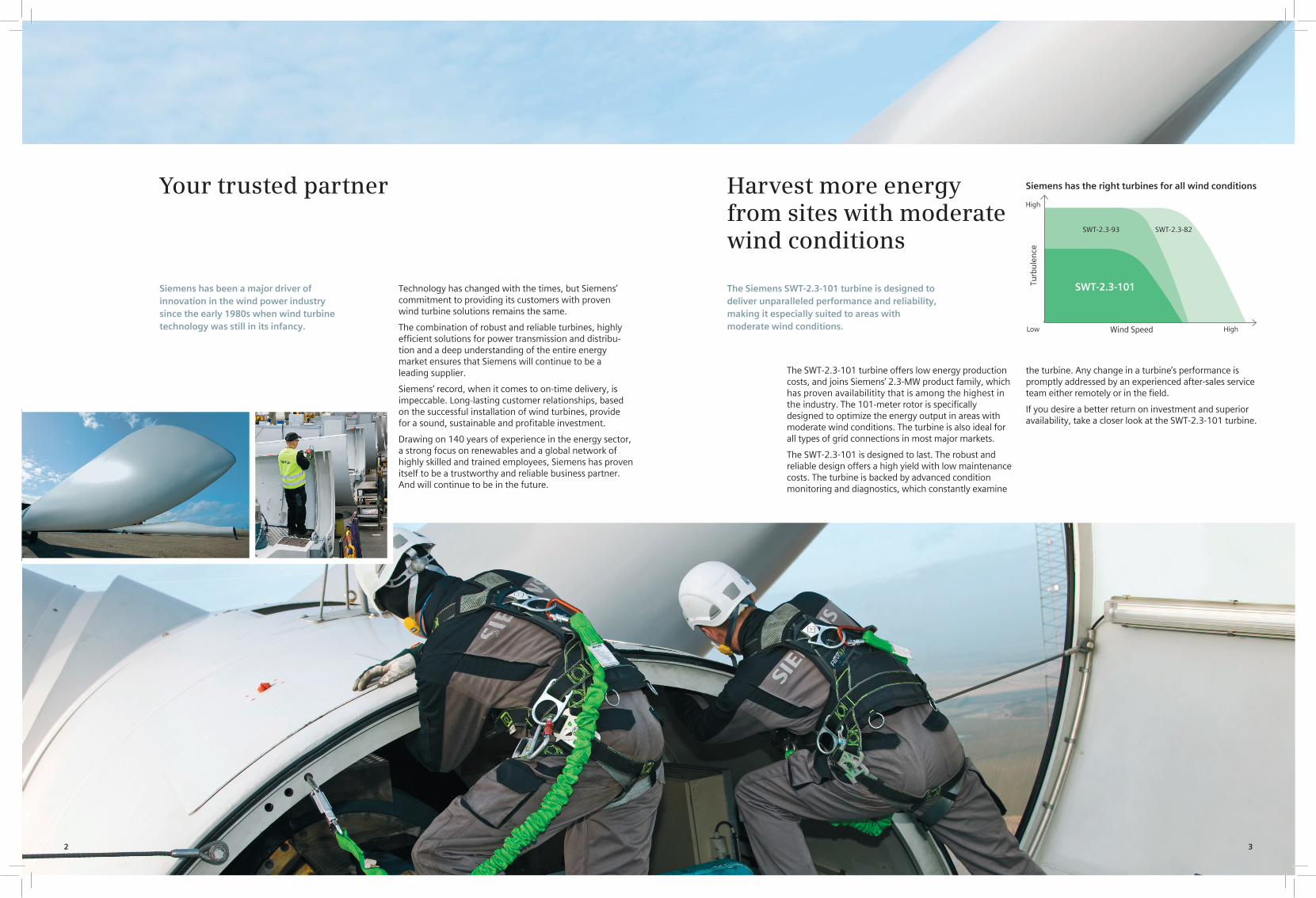
The Siemens SWT-2.3-101 turbine is designed to deliver unparalleled performance and reliability, making it especially suited to areas with moderate wind conditions.
The SWT-2.3-101 turbine offers low energy production costs, and joins Siemens’ 2.3-MW product family, which has proven availabilitity that is among the highest in the industry. The 101-meter rotor is specifically designed to optimize the energy output in areas with moderate wind conditions. The turbine is also ideal for all types of grid connections in most major markets.
The SWT-2.3-101 is designed to last. The robust and reliable design offers a high yield with low maintenance costs. The turbine is backed by advanced condition monitoring and diagnostics, which constantly examine
Siemens has been a major driver of innovation in the wind power industry since the early 1980s when wind turbine technology was still in its infancy.
Technology has changed with the times, but Siemens’ commitment to providing its customers with proven wind turbine solutions remains the same.
The combination of robust and reliable turbines, highly efficient solutions for power transmission and distribu-tion and a deep understanding of the entire energy market ensures that Siemens will continue to be a leading supplier.
Siemens’ record, when it comes to on-time delivery, is impeccable. Long-lasting customer relationships, based on the successful installation of wind turbines, provide for a sound, sustainable and profitable investment.
Drawing on 140 years of experience in the energy sector, a strong focus on renewables and a global network of highly skilled and trained employees, Siemens has proven itself to be a trustworthy and reliable business partner. And will continue to be in the future.
the turbine. Any change in a turbine’s performance is promptly addressed by an experienced after-sales service team either remotely or in the field.
If you desire a better return on investment and superior availability, take a closer look at the SWT-2.3-101 turbine.
Siemens has the right turbines for all wind conditions
High
Low High
Turb
ulen
ce
Wind Speed
SWT-2.3-93 SWT-2.3-82
SWT-2.3-101

Designed for life Siemens turbines are designed to last. The robust design of the SWT-2.3-101 allows for trouble-free output throughout the complete lifecycle of the turbine.
The blades are made of fiberglass-reinforced epoxy in Siemens’ proprietary IntegralBlade® manufacturing process. The blades are cast in one piece in a closed process, which eliminates the traditional weaknesses found at glue joints in other manufacturers’ blades. Like the turbine itself, the blades are designed to last.
Climate control within the turbine protects vital equipment from the outside environment. The turbine also offers controlled-wear strategies for critical components, which results in a further reduc-tion of maintenance costs.
Safety first Safety is at the heart of all Siemens operations. From production to installation, operation and service, Siemens strives to set the standard in safety.
The fail-to-safe capabilities within a turbine, combined with Siemens’ superior lightning protection system, are designed to enhance security for the turbine.
4 5
No compromise on reliability
Optimum energy at moderate wind conditions
SWT-2.3-101: Newest member of the extremely reliable product family
Advanced operations support Given the logistical challenges associated with servicing wind farms, Siemens has equipped its turbines with a Turbine Condition Monitoring (TCM) system that reduces the need for on-site servicing.
Continuous monitoring of turbines allows for the discovery of small faults before they become major problems.
The TCM system continuously checks the external and internal condition of the wind turbine. Twenty-four hours a day, seven days a week precise measurements are taken of vibrations in the gear-box, the generator and the main shaft bearings. The system instantly detects deviations from normal operating conditions.
Using the knowledge gained from monitoring thousands of turbines over the years, Siemens’ experts are exceptionally skilled at analyzing and predicting faults within a turbine. This allows Siemens to proactively plan the service and maintenance of the turbines as each fault can be categorized and prioritized based on the severity of the fault. Siemens can then determine the most appropriate course of action to keep the turbine running at its best.
Superior performance gives higher yields
without slip rings contributes to exceptional reliability. The innova-tive design of the SWT-2.3-101 allows for longer service intervals.
Superior grid compliance The Siemens NetConverter® system is designed for maximum flexibility in the turbine’s response to voltage and frequency variations, fault ride-through capability and output adjustment. The advanced wind farm control system provides state-of-the-art fleet management.
Proven track record Siemens has a proven track record of providing reliable turbines that last. The world’s first offshore wind farm in Vindeby, Denmark, was installed in 1991 and is still fully operational. In California, Siemens installed over 1,100 turbines between 1983 and 1990, with 97% still in operation today. Siemens takes its commitment to reliability seriously and prides itself on the long lifespan that its turbines have demonstrated.
Harvesting more energy The SWT-2.3-101 wind turbine is designed to increase the energy returns from sites with moderate wind conditions. Advanced blade technology also allows for quieter operation. The B49 blade with a rotor diameter of 101 meters and pitch regulation optimizes power output and increases control over the energy output.
High availability Currently, the Siemens fleet of 2.3-MW wind turbines sets the industry standard for availability. The SWT-2.3-101 will build on the reputation for reliability that the market has come to expect from a Siemens Wind turbine.
High yield with minimal maintenance Siemens optimizes the return on investment in its wind turbines through intelligent maintenance that ensures the turbine to deliver high yield with low operational costs.
The rugged structural design, combined with an automatic lubrica-tion system, internal climate control and a generator system

6 7
Nacelle arrangement
1. Spinner
2. Spinner bracket
3. Blade
4. Pitch bearing
5. Rotor hub
6. Main bearing
7. Main shaft
8. Gearbox
9. Brake disc
Sales power curve
The calculated power curve data are valid for standard conditions of 15 degrees Celsius air temperature, 1013 hPa air pressure and 1.225 kg/m3 air density, clean rotor blades and horizontal, undisturbed air flow. The calculated curve data are preliminary.
10. Coupling
11. Generator
12. Service crane
13. Meteorological sensors
14. Tower
15. Yaw ring
16. Yaw gear
17. Nacelle bedplate
18. Oil filter
19. Canopy
20. Generator fan
Generator
Type Asynchronous Nominal power 2,300 kW Voltage 690 V Cooling system Integrated heat exchanger
Yaw system
Type Active
Monitoring system
SCADA system WebWPS Remote control Full turbine control
Tower
Type Cylindrical and/or tapered tubular Hub height 80 m or site-specific
Operational data
Cut-in wind speed 3-4 m/s Rated power at 12-13 m/s Cut-out wind speed 25 m/s Maximum 3 s gust 55 m/s (standard version) 60 m/s (IEC version)
Weights
Rotor 62 tons Nacelle 82 tons Tower for 80-m hub height 162 tons
Rotor
Diameter 101 m Swept area 8,000 m2 Rotor speed 6-16 rpm Power regulation Pitch regulation with variable speed
Blades
Type B49 Length 49 m
Aerodynamic brake
Type Full-span pitching Activation Active, hydraulic
Transmission system
Gearbox type 3-stage planetary/helical Gearbox ratio 1:91 Gearbox oil filtering Inline and offline Gearbox cooling Separate oil cooler Oil volume Approximately 400 l
Mechanical brake
Type Hydraulic disc brake
1
2 3
13
1615 18 19
4 5 6 7 8 9 1210
11
1714 20
Technical specifications
2200
2000
1800
1600
1400
1200
1000
800
600
400
200
0
0 5 10 15 20
Power [kW]
Wind [m/s]

The new standard for moderate wind conditions Siemens Wind Turbine SWT-2.3-101
Answers for energy.

2

Harvest more energy from sites with moderate wind conditions
The Siemens SWT-2.3-101 turbine is designed to deliver unparalleled performance and reliability, making it especially suited to areas with moderate wind conditions.
The SWT-2.3-101 turbine offers low energy production costsand joins Siemens’ 2.3-MW product family, which has proven availabilitity that is among the highest in the industry. The 101-meter rotor is specifically designed to optimize the energy output in areas with moderate wind conditions. The turbine is also ideal for all types of grid connections in most major markets.
Your trusted partner
Siemens has been a major driver of innovation in the wind power industry since the early 1980s when wind turbine technology was still in its infancy.
Technology has changed with the times, but Siemens’ commitment to providing its customers with proven wind turbine solutions remains the same.
The combination of robust and reliable turbines, highly efficient solutions for power transmission and distribution and a deep understanding of the entire energy market ensures that Siemens will continue to be a leading supplier.
Siemens’ record, when it comes to on-time delivery, is impeccable. Long-lasting customer relationships, based on the successful installation of wind turbines, provide for a sound, sustainable and profitable investment.
Drawing on 140 years of experience in the energy sector, a strong focus on renewables and a global network of highly skilled and trained employees, Siemens has proven itself to be a trustworthy and reliable business partner. And will continue to be in the future.
Siemens has the right turbines for all wind conditions
High
Low High
Turb
ule
nce
Wind Speed
SWT-2.3-93 SWT-2.3-82
SWT-2.3-101
The SWT-2.3-101 is designed to last. The robust and reliable design offers a high yield with low maintenance costs. The turbine is backed by advanced condition monitoring and diagnostics, which constantly examine the turbine. Any change in a turbine’s performance is promptly addressed by an experienced after-sales service team either remotely or in the field.
If you desire a better return on investment and superior availability, take a closer look at the SWT-2.3-101 turbine.
3

Superior performance gives higher yields
Superior grid compliance
The Siemens NetConverter® system is designed for maximum flexibility in the turbine’s response to voltage and frequency variations, fault ride-through capability and output adjustment. The advanced wind farm control system provides state-of-the-art fleet management.
Proven track record
Siemens has a proven track record of providing reliable turbines that last. The world’s first offshore wind farm in Vindeby, Denmark, was installed in 1991 and is still fully operational. In California, Siemens installed over 1,100 turbines between 1983 and 1990, with 97% still in operation today. Siemens takes its commitment to reliability seriously and prides itself on the long lifespan that its turbines have demonstrated.
Optimum energy at moderate wind conditions
Harvesting more energy
The SWT-2.3-101 wind turbine is designed to increase the energy returns from sites with moderate wind conditions. Advanced blade technology also allows for quieter operation. The B49 blade with a rotor diameter of 101 meters and pitch regulation optimizes power output and increases control over the energy output.
High availability
Currently, the Siemens fleet of 2.3-MW wind turbines sets the industry standard for availability. The SWT-2.3-101 will build on the reputation for reliability that the market has come to expect from a Siemens Wind turbine.
High yield with minimal maintenance
Siemens optimizes the return on investment in its wind turbines through intelligent maintenance that ensures the turbine to deliver high yield with low operational costs.
The rugged structural design, combined with an automatic lubrication system, internal climate control and a generator system without slip rings contributes to exceptional reliability. The innovative design of the SWT-2.3-101 allows for longer service intervals.
4

SWT-2.3-101: Newest member of the extremely reliable product family
Designed for life
Siemens turbines are designed to last. The robust design of the SWT-2.3-101 allows for trouble-free output throughout the complete lifecycle of the turbine.
The blades are made of fiberglass-reinforced epoxy in Siemens’ proprietary IntegralBlade® manufacturing process. The blades are cast in one piece in a closed process, which eliminates the traditional weaknesses found at glue joints in other manufacturers’ blades. Like the turbine itself, the blades are designed to last.
Climate control within the turbine protects vital equipment from the outside environment. The turbine also offers controlled-wear strategies for critical components, which results in a further reduction of maintenance costs.
Safety first
Safety is at the heart of all Siemens operations. From production to installation, operation and service, Siemens strives to set the standard in safety.
The fail-to-safe capabilities within a turbine, combined with Siemens’ superior lightning protection system, are designed to enhance security for the turbine.
No compromise on reliability
Advanced operations support
Given the logistical challenges associated with servicing wind farms, Siemens has equipped its turbines with a Turbine Condition Monitoring (TCM) system that reduces the need for on-site servicing.
Continuous monitoring of turbines allows for the discovery of small faults before they become major problems.
The TCM system continuously checks the external and internal condition of the wind turbine. Twenty-four hours a day, seven days a week precise measurements are taken of vibrations in the gearbox, the generator and the main shaft bearings. The system instantly detects deviations from normal operating conditions.
Using the knowledge gained from monitoring thousands of turbines over the years, Siemens’ experts are exceptionally skilled at analyzing and predicting faults within a turbine. This allows Siemens to proactively plan the service and maintenance of the turbines as each fault can be categorized and prioritized based on the severity of the fault. Siemens can then determine the most appropriate course of action to keep the turbine running at its best.
5

Yaw system
Type Active
Monitoring system
SCADA system WebWPSRemote control Full turbine control
Tower
Type Cylindrical and/or tapered tubularHub height 80 m or site-specific
Operational data
Cut-in wind speed 3-4 m/sRated power at 12-13 m/sCut-out wind speed 25 m/sMaximum 3 s gust 55 m/s (standard version) 60 m/s (IEC version)
Weights
Rotor 62 tonsNacelle 82 tonsTower for 80-m hub height 162 tons
Rotor
Diameter 101 mSwept area 8,000 m2Rotor speed 6-16 rpmPower regulation Pitch regulation with variable speed
Blades
Type B49Length 49 m
Aerodynamic brake
Type Full-span pitchingActivation Active, hydraulic
Transmission system
Gearbox type 3-stage planetary/helical Gearbox ratio 1:91Gearbox oil filtering Inline and offlineGearbox cooling Separate oil coolerOil volume Approximately 400 l
Mechanical brake
Type Hydraulic disc brake
Generator
Type AsynchronousNominal power 2,300 kWVoltage 690 VCooling system Integrated heat exchanger
Technical specifications
6

Sales power curve
The calculated power curve data are valid for standard conditions of 15 degrees Celsius air temperature, 1013 hPa air pressure and 1.225 kg/m3 air density, clean rotor blades and horizontal, undisturbed air flow. The calculated curve data are preliminary.
Nacelle arrangement
1. Spinner
2. Spinner bracket
3. Blade
4. Pitch bearing
5. Rotor hub
6. Main bearing
7. Main shaft
8. Gearbox
9. Brake disc
10. Coupling
11. Generator
12. Service crane
13. Meteorological sensors
14. Tower
15. Yaw ring
16. Yaw gear
17. Nacelle bedplate
18. Oil filter
19. Canopy
20. Generator fan
0 5 10 15 20
Power [kW]
Wind [m/s]
1
2 3
13
1615 18 19
4 5 6 7 8 9 1210
11
1714 20
2200
2000
1800
1600
1400
1200
1000
800
600
400
200
0
7

www.siemens.com/energy
Published by and copyright © 2009:Siemens AGEnergy SectorFreyeslebenstrasse 191058 Erlangen, Germany
Siemens AGSiemens Wind Power A/SBorupvej 167330 Brande, Denmarkwww.siemens.com/wind
For more information, please contact our Customer Support Center.Phone: +49 180 524 70 00Fax: +49 180 524 24 71(Charges depending on provider)E-mail: [email protected]
Renewable Energy DivisionOrder No. E50001-W310-A121-X-4A00Printed in GermanyDispo 34804, c4bs No. 7491fb 2225 WS 10095.
Printed on elementary chlorine-free bleached paper.
All rights reserved. Trademarks mentioned in this document are the property of Siemens AG, its affiliates, or their respective owners.
Subject to change without prior notice. The information in this document contains general descriptions of the technical options available, which may not apply in all cases. The required technical options should therefore be specified in the contract.


Acoustic Emission, SWT-2.3-101
Document ID: E R WP-EN-AJJ rev.0 PE/AJJ / 2009.05.12
Conveyed confidentially as trade secret
Siemens Wind Power A/S © All Rights Reserved 2009
1 / 1SWT-2 3-101 80m Acoustic Emission rev.May12 2009.doc
SWT-2.3-101 Acoustic Emission Sound Power Levels The warranted sound power levels are presented with reference to the code IEC 61400-11:2002 with amendment 1 dated 2006-05 based on a hub height of 80 m and a roughness length of 0.05 m as described in the IEC code. The sound power levels (LWA) presented are valid for the corresponding wind speeds referenced to a height of 10 m above ground level.
Wind speed [m/s] 4 5 6 7 8 9 10 11 12 Up to 18
Sound power level 95,1 99,8 104,6 106,0 106,0 106,0 106,0 106,0 106,0 106,0Tabel 1: Noise emmision, LWA [dB(A) re 1 pW] Typical Octave Band Typical, not warranted octave band spectra are tabulated below for 6 and 8 m/s referenced to 10m height. Octave band, center frequency [Hz] 63 125 250 500 1000 2000 4000 8000 Sound power level 80,6 91,8 95.9 99,5 99,7 96,3 88.9 84.6
Table 2: Typical octave band for 6 m/s Octave band, center frequency [Hz] 63 125 250 500 1000 2000 4000 8000 Sound power level 82.5 93.4 97,1 101,1 101.1 97,4 90,2 86,2
Table 3: Typical octave band for 8 m/s

Acoustic Emission, SWT-2.3-101
Document ID: E R WP-EN-AJJ rev.0 PE/AJJ / 2009.05.12
Conveyed confidentially as trade secret
Siemens Wind Power A/S © All Rights Reserved 2009
1 / 1SWT-2 3-101 low noise 80m Acoustic Emission rev May12 2009.doc
SWT-2.3-101, Low Noise Acoustic Emission Sound Power Levels The warranted sound power levels are presented with reference to the code IEC 61400-11:2002 with amendment 1 dated 2006-05 based on a hub height of 80 m and a roughness length of 0.05 m as described in the IEC code. The sound power levels (LWA) presented are valid for the corresponding wind speeds referenced to a height of 10 m above ground level.
Wind speed [m/s] 4 5 6 7 8 9 10 11 12 Up to 18
Sound power level 95,1 99,8 103,7 105,0 105,0 105,0 105,0 105,0 105,0 105,0Tabel 1: Noise emmision, LWA [dB(A) re 1 pW] Typical Octave Band Typical, not warranted octave band spectra are tabulated below for 6 and 8 m/s referenced to 10m height. Octave band, center frequency [Hz] 63 125 250 500 1000 2000 4000 8000 Sound power level 81.3 92.5 95.7 98.2 98.3 95.8 88.0 83.6
Table 2: Typical octave band for 6 m/s Octave band, center frequency [Hz] 63 125 250 500 1000 2000 4000 8000 Sound power level 82.4 93.0 96.0 99.8 100.1 96.5 89.6 85.7
Table 3: Typical octave band for 8 m/s

Acoustic Emission, SWT-2.3-93
Document ID: E R WP-EN431 rev.1PE / 2009.05.12
Conveyed confidentially as trade secret
Siemens Wind Power A/S © All Rights Reserved 2009
1 / 1SWT-2 3-93 80m Acoustic Emission May12 2009.doc
SWT-2.3-93 Acoustic Emission Sound Power Levels The warranted sound power levels are presented with reference to the code IEC 61400-11:2002 with amendment 1 dated 2006-05 based on a hub height of 80 m and a roughness length of 0.05 m as described in the IEC code. The sound power levels (LWA) presented are valid for the corresponding wind speeds referenced to a height of 10 m above ground level.
Wind speed [m/s] 4 5 6 7 8 9 10 11 12 Up to 18
Sound power level 91.3 99.1 103.4 104.9 105.1 105.0 105.0 105.0 105.0 105.0Tabel 1: Noise emmision, LWA [dB(A) re 1 pW] Typical Octave Band Typical, not warranted octave band spectra are tabulated below for 6 and 8 m/s referenced to 10m height. Octave band, center frequency [Hz] 63 125 250 500 1000 2000 4000 8000 Sound power level 81.4 92.2 99.0 98.4 94.7 91.7 88.2 82.0
Table 2: Typical octave band for 6 m/s Octave band, center frequency [Hz] 63 125 250 500 1000 2000 4000 8000 Sound power level 84.2 93.2 99.9 100.3 97.4 93.9 88.6 84.9
Table 3: Typical octave band for 8 m/s

Acoustic Emission, SWT-2.3-93
Document ID: E R WP-EN431-LNPE / 2009.05.12
Conveyed confidentially as trade secret
Siemens Wind Power A/S © All Rights Reserved 2009
1 / 1SWT-2 3-93 80m Low Noise Acoustic Emission May12.2009.doc
SWT-2.3-93, Low Noise Acoustic Emission Sound Power Levels The warranted sound power levels are presented with reference to the code IEC 61400-11:2002 with amendment 1 dated 2006-05 based on a hub height of 80 m and a roughness length of 0.05 m as described in the IEC code. The sound power levels (LWA) presented are valid for the corresponding wind speeds referenced to a height of 10 m above ground level.
Wind speed [m/s] 4 5 6 7 8 9 10 11 12 Up to 18
Sound power level 91.3 98.9 103.0 104.0 104.0 104.0 104.0 104.0 104.0 104.0Tabel 1: Noise emmision, LWA [dB(A) re 1 pW] Typical Octave Band Typical, not warranted octave band spectra are tabulated below for 6 and 8 m/s referenced to 10m height. Octave band, center frequency [Hz] 63 125 250 500 1000 2000 4000 8000 Sound power level 83.3 93.6 99.2 97.1 93.2 91.4 86.8 79.6
Table 2: Typical octave band for 6 m/s Octave band, center frequency [Hz] 63 125 250 500 1000 2000 4000 8000 Sound power level 85.1 93.5 98.7 98.8 96.5 93.1 88.6 85.1
Table 3: Typical octave band for 8 m/s