catalogo TEN BLOC 2018 · applicata entro il quale il corpo elastico, rilasciato, ritorna alle sue...
56
TEN BLOC 27 BREVETTATO – PATENDED C 2013
Transcript of catalogo TEN BLOC 2018 · applicata entro il quale il corpo elastico, rilasciato, ritorna alle sue...
TEN BLOC
27
BREVETTATO – PATENDED
C 2013
PRESENTAZIONE AZIENDA E TECNOLOGIAPRESENTATION OF THE COMPANY AND TECHNOLOGY
8
TECNOLOGIANumerosi sono i prodotti illustrati in questo catalogo, vedi tabella a pag.06, ed una parte rilevante è riferita agli
elementi elastici assiali ed a rotazione, che principalmente vengono impiegati come tendicatena e tendicinghia automatici.
MOLLE
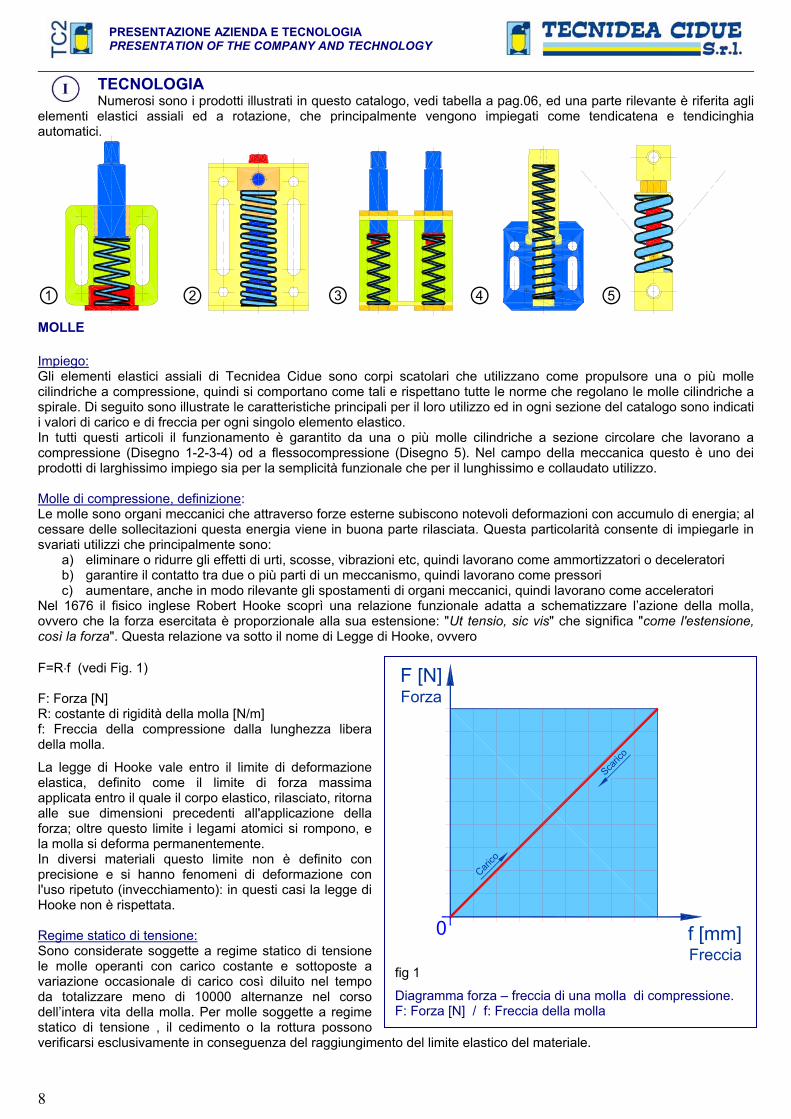
Impiego:Gli elementi elastici assiali di Tecnidea Cidue sono corpi scatolari che utilizzano come propulsore una o più molle cilindriche a compressione, quindi si comportano come tali e rispettano tutte le norme che regolano le molle cilindriche a spirale. Di seguito sono illustrate le caratteristiche principali per il loro utilizzo ed in ogni sezione del catalogo sono indicati i valori di carico e di freccia per ogni singolo elemento elastico. In tutti questi articoli il funzionamento è garantito da una o più molle cilindriche a sezione circolare che lavorano a compressione (Disegno 1-2-3-4) od a flessocompressione (Disegno 5). Nel campo della meccanica questo è uno dei prodotti di larghissimo impiego sia per la semplicità funzionale che per il lunghissimo e collaudato utilizzo.
Molle di compressione, definizione:Le molle sono organi meccanici che attraverso forze esterne subiscono notevoli deformazioni con accumulo di energia; al cessare delle sollecitazioni questa energia viene in buona parte rilasciata. Questa particolarità consente di impiegarle in svariati utilizzi che principalmente sono:
a) eliminare o ridurre gli effetti di urti, scosse, vibrazioni etc, quindi lavorano come ammortizzatori o deceleratori b) garantire il contatto tra due o più parti di un meccanismo, quindi lavorano come pressori c) aumentare, anche in modo rilevante gli spostamenti di organi meccanici, quindi lavorano come acceleratori
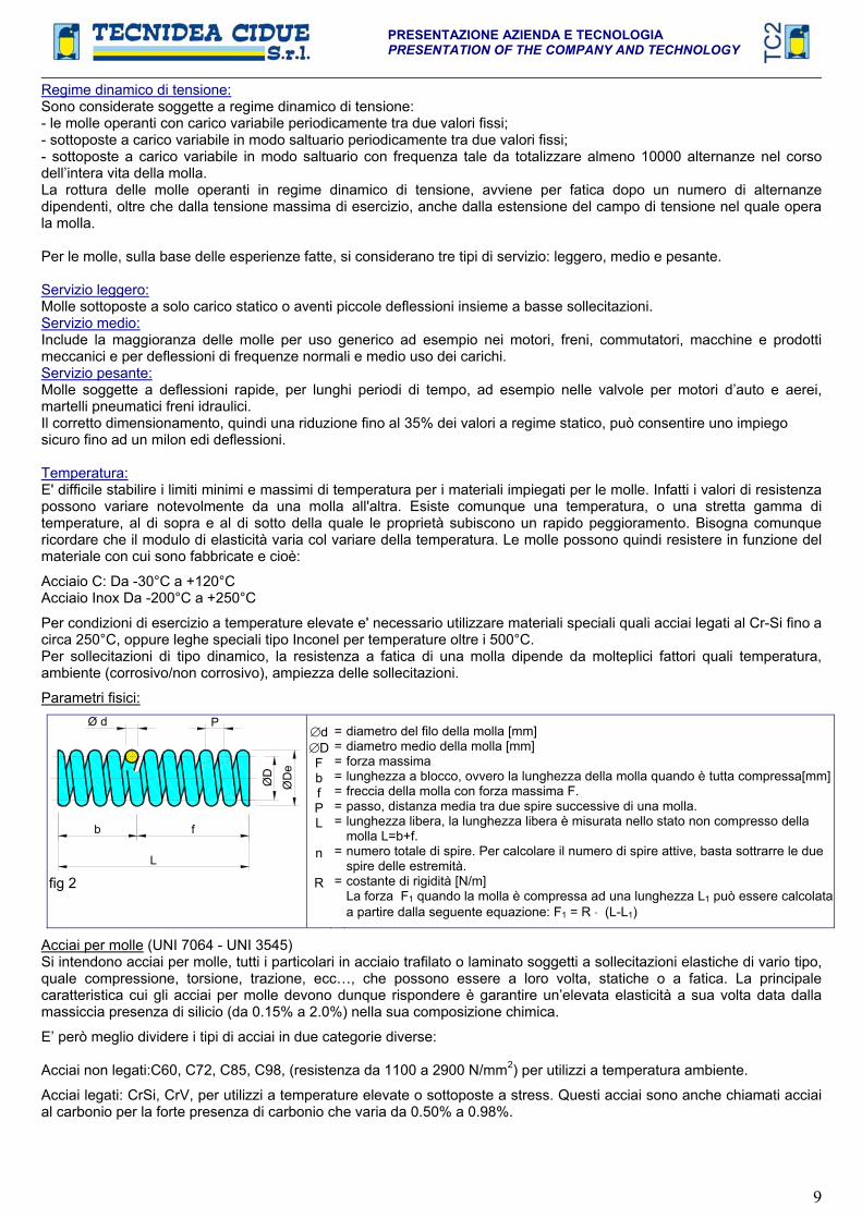
Nel 1676 il fisico inglese Robert Hooke scoprì una relazione funzionale adatta a schematizzare l’azione della molla, ovvero che la forza esercitata è proporzionale alla sua estensione: "Ut tensio, sic vis" che significa "come l'estensione, così la forza". Questa relazione va sotto il nome di Legge di Hooke, ovvero
F=R f (vedi Fig. 1)
F: Forza [N]R: costante di rigidità della molla [N/m] f: Freccia della compressione dalla lunghezza libera della molla.
La legge di Hooke vale entro il limite di deformazione elastica, definito come il limite di forza massima applicata entro il quale il corpo elastico, rilasciato, ritorna alle sue dimensioni precedenti all'applicazione della forza; oltre questo limite i legami atomici si rompono, e la molla si deforma permanentemente. In diversi materiali questo limite non è definito con precisione e si hanno fenomeni di deformazione con l'uso ripetuto (invecchiamento): in questi casi la legge di Hooke non è rispettata.
Regime statico di tensione:Sono considerate soggette a regime statico di tensione le molle operanti con carico costante e sottoposte a variazione occasionale di carico così diluito nel tempo da totalizzare meno di 10000 alternanze nel corso dell’intera vita della molla. Per molle soggette a regime statico di tensione , il cedimento o la rottura possono verificarsi esclusivamente in conseguenza del raggiungimento del limite elastico del materiale.
F [N]
f [mm]0
Carico
Scaric
o
Forza
Frecciafig 1
Diagramma forza – freccia di una molla di compressione. F: Forza [N] / f: Freccia della molla
PRESENTAZIONE AZIENDA E TECNOLOGIA PRESENTATION OF THE COMPANY AND TECHNOLOGY
9
Regime dinamico di tensione:Sono considerate soggette a regime dinamico di tensione: - le molle operanti con carico variabile periodicamente tra due valori fissi; - sottoposte a carico variabile in modo saltuario periodicamente tra due valori fissi; - sottoposte a carico variabile in modo saltuario con frequenza tale da totalizzare almeno 10000 alternanze nel corso dell’intera vita della molla.La rottura delle molle operanti in regime dinamico di tensione, avviene per fatica dopo un numero di alternanze dipendenti, oltre che dalla tensione massima di esercizio, anche dalla estensione del campo di tensione nel quale opera la molla.
Per le molle, sulla base delle esperienze fatte, si considerano tre tipi di servizio: leggero, medio e pesante.
Servizio leggero:Molle sottoposte a solo carico statico o aventi piccole deflessioni insieme a basse sollecitazioni. Servizio medio:Include la maggioranza delle molle per uso generico ad esempio nei motori, freni, commutatori, macchine e prodotti meccanici e per deflessioni di frequenze normali e medio uso dei carichi. Servizio pesante:Molle soggette a deflessioni rapide, per lunghi periodi di tempo, ad esempio nelle valvole per motori d’auto e aerei, martelli pneumatici freni idraulici. Il corretto dimensionamento, quindi una riduzione fino al 35% dei valori a regime statico, può consentire uno impiego sicuro fino ad un milon edi deflessioni.
Temperatura:E' difficile stabilire i limiti minimi e massimi di temperatura per i materiali impiegati per le molle. Infatti i valori di resistenza possono variare notevolmente da una molla all'altra. Esiste comunque una temperatura, o una stretta gamma di temperature, al di sopra e al di sotto della quale le proprietà subiscono un rapido peggioramento. Bisogna comunque ricordare che il modulo di elasticità varia col variare della temperatura. Le molle possono quindi resistere in funzione del materiale con cui sono fabbricate e cioè:
Acciaio C: Da -30°C a +120°C Acciaio Inox Da -200°C a +250°C
Per condizioni di esercizio a temperature elevate e' necessario utilizzare materiali speciali quali acciai legati al Cr-Si fino a circa 250°C, oppure leghe speciali tipo Inconel per temperature oltre i 500°C. Per sollecitazioni di tipo dinamico, la resistenza a fatica di una molla dipende da molteplici fattori quali temperatura, ambiente (corrosivo/non corrosivo), ampiezza delle sollecitazioni.
Parametri fisici:
ØD
L
fb
ØD
e
PØ d
fig 2
dD
FbfPL
n
R
=======
=
=
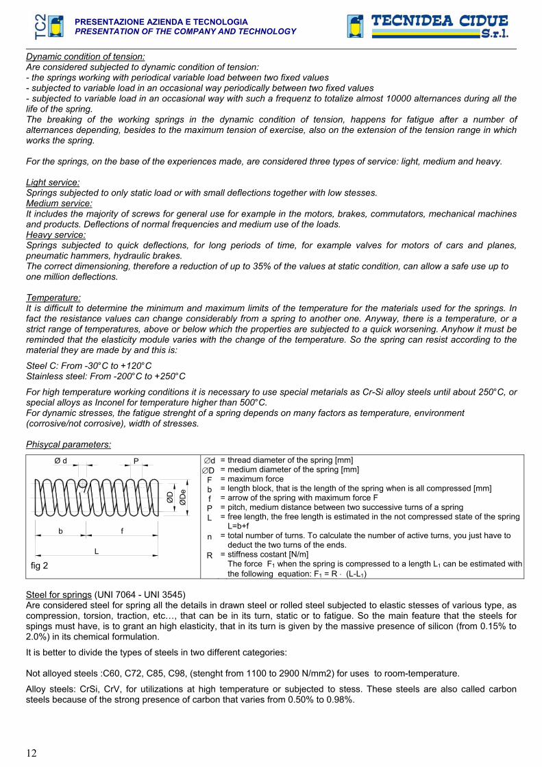
diametro del filo della molla [mm] diametro medio della molla [mm] forza massima lunghezza a blocco, ovvero la lunghezza della molla quando è tutta compressa[mm]freccia della molla con forza massima F.passo, distanza media tra due spire successive di una molla. lunghezza libera, la lunghezza libera è misurata nello stato non compresso della molla L=b+f. numero totale di spire. Per calcolare il numero di spire attive, basta sottrarre le due spire delle estremità. costante di rigidità [N/m] La forza F1 quando la molla è compressa ad una lunghezza L1 può essere calcolata a partire dalla seguente equazione: F1 = R (L-L1)
Acciai per molle (UNI 7064 - UNI 3545) Si intendono acciai per molle, tutti i particolari in acciaio trafilato o laminato soggetti a sollecitazioni elastiche di vario tipo, quale compressione, torsione, trazione, ecc…, che possono essere a loro volta, statiche o a fatica. La principale caratteristica cui gli acciai per molle devono dunque rispondere è garantire un’elevata elasticità a sua volta data dalla massiccia presenza di silicio (da 0.15% a 2.0%) nella sua composizione chimica.
E’ però meglio dividere i tipi di acciai in due categorie diverse:
Acciai non legati:C60, C72, C85, C98, (resistenza da 1100 a 2900 N/mm2) per utilizzi a temperatura ambiente.
Acciai legati: CrSi, CrV, per utilizzi a temperature elevate o sottoposte a stress. Questi acciai sono anche chiamati acciai al carbonio per la forte presenza di carbonio che varia da 0.50% a 0.98%.

PRESENTAZIONE AZIENDA E TECNOLOGIAPRESENTATION OF THE COMPANY AND TECHNOLOGY
10
Generalmente questi acciai vengono lavorati a freddo per poi subire un trattamento termico al fine di eliminare tutti gli stress e le tensione che si accumulano in fase di lavorazione; in seguito a questo passaggio, le caratteristiche meccaniche dell’acciaio rimangono invariate e costanti nel tempo garantendo reazioni durature nei limiti accettabili per i materiali e le condizioni di lavoro richieste. Le principali norme di riferimento sono UNI 3823 EN 10270-1/2 DIN 17223.
Esempio di analisi chimica di 3 tipi di molle con differenti acciai:
PERCENTUALE DEI COMPONENTI C% Mn% Si% S% P% Cu% N% Fe%
Tipo 1 C72: 0.60-0.80 0.50-0.90 0.10-0.30 <0.025 <0.025 <0.20 <0.08 RESTO Tipo 2 C85: >0.70 0.50-0.90 0.10-0.30 <0.025 <0.025 <0.20 <0.08 RESTO Tipo 2 C95: 0.8-1.0 0.50-0.90 0.10-0.30 <0.025 <0.025 <0.20 <0.08 RESTO
Gli acciai per molle hanno come proprietà caratteristica quella di possedere un elevato limite di elasticità che può ottenersi in due modi : - con incrudimento per deformazione plastica a freddo mediante trafilatura o laminazione, praticata su acciai al carbonio o debolmente legati - con trattamento termico di tempra e rinvenimento alla temperatura di 400-450° eseguito su acciai a medio tenore di carbonio, legati al Silicio o al Cromo e Vanadio. Entrambe le soluzione consentono di ottenere carichi di snervamento molto elevati. Le tabelle di unificazione per questi acciai sono la UNI 7064 e la UNI 3545.
Frequenza propria “fn“ La frequenza propria o naturale in un sistema semplice massa-molla è data da:
fn= MR
21 , dove M è la massa del peso attaccato alla molla.
MATERIALI E TRATTAMENTI SUPERFICIALI
Tecnidea Cidue all’interno dei suoi prodotti utilizza diversi materiali e trattamenti superficiali per la realizzazione dei suoiarticoli:
Acciaio: nei pezzi realizzati mediante tornitura sono generalmente utilizzati acciai addizionati al piombo come il 11SMnPb37 (AVP). I pezzi realizzati per taglio laser, fresatura o piegatura o saldatura sono realizzati in Fe 360. La bulloneria utilizzata è in classe 8.8.
Ottone: i pezzi di scorrimento vengono realizzati per tornitura in Ottone Ot 58
Lega di Alluminio: nei pezzi realizzati in pressofusione è utilizzata la lega 46100, nei pezzi realizzati in fusione in conchiglia è utilizzata la lega EN AB 44100, mentre nei profilati realizzati da estrusione è utilizzata la lega T6060.
Polietilene: nei pezzi realizzati per lo scorrimento delle catene (pattini e rotelle) è utilizzato il polietilene PE 1000 generalmente colore verde, con peso molecolare 1.000.000
Poliammide: nei rulli per cinghie è utilizzato il poliammide PA 6 + So.Mo.
I trattamenti superficiali sono:
Sabbiatura: i pezzi in alluminio o in acciaio inox (piastre di connessione e forcelle della serie di prodotti “BLU”) sono sabbiati per migliorare l’effetto estetico e le caratteristiche di anticorrosione.
Zincatura elettrolitica: i pezzi trattati sono realizzati con almeno zincatura elettrolitica Fe/Zn 5 c1A.
Verniciatura a forno: i pezzi verniciati sono realizzati con verniciatura ricotta a forno a 200°C o con verniciatura spray.
Su richiesta si possono realizzare articoli o componenti con trattamenti superficiali diversi da quelli standard come la nichelatura o la zincatura a caldo.

PRESENTAZIONE AZIENDA E TECNOLOGIA PRESENTATION OF THE COMPANY AND TECHNOLOGY
11
TECHNOLOGYMany are the products showed in this catalogue, see table at page 06, and a remarkable part concerns the axial
and rotational elastic elements, that are mainly used as automatic chain tensioners and belt tensioners.
SPRINGS
Use:
The axial elastic elements of Tecnidea Cidue are box-shaped bodies that use as propulsor one or more cylindric compression springs, so they act in this manner and they respect all the rules that regulate the cylindrical spiral springs. Herewith are illustarted the main features for their use and in each section of the catalogue are indicated the values of load and of arrow for each single elastic element. In all these articles the functioning is granted by one or more cylindrical springs with circular sections that work through compression (drawing 1-2-3-4) or through combined compressive and bending stress (drawing 5). In mechanics this is one of the products with an extensive use both for the functional semplicity and for the very long and the tested utilization. Compression spring, definition:Springs are mechanical units that, through external forces, suffer many deformations with accumulation of energy; when the stresses cease, this energy is in a large part released. This peculiarity allows to use them in various ways, which are mainly:
a) to eliminate or to reduce the effects of impacts, shakes and vibrations etc, so they work as shock absorbers and decelerator unit;
b) to grant the contact between two or more parts of a mechanism, so they work as down holders; c) to increase, also in a relevant way, the movements of mechanical units, so they work as accelerator.
In 1676 the english physicist Rober Hooke discovered a functional relation suitable to schematize the action of the spring, or rather that the force exerted is proportional to its extention: "Ut tensio, sic vis" that is “as the extention, so is the force”. This relation is called the Law of Hooke, or rather F=R f (see figure1)
F: Force [N]R: costant of stiffness of the spring [N/m] f: Compression arrow from the free length of the spring.
The law of Hooke is valid within the limit of elastic deformation, defined as the limit of maximum applied force within which the elastic released body returns to its dimensions previous to the application of the force; over this limit the linkages break themselves, and the spring deforms itself permanently. In many materials this limit is not defined with precision and there are phenomena of deformation with the repeated utilization (ageing): in these cases the law of Hooke is not respected.
Static condition of tension:Are considered subjected to static condition of tension, the springs working with a constant load and subjected to an occasional change of load that is so deferred over the time to totalize less than 10000 alternances during all the life of the spring. For springs subjected to static condition of tension, the settling or the braking can happen exclusively consequently to the reaching of the elastic limit of the spring.
F [N]
f [mm]0
Carico
Scaric
o
Forza
fig 1
Diagram force – travel of a compression spring F: Forza [N] / f: Freccia della molla
PRESENTAZIONE AZIENDA E TECNOLOGIAPRESENTATION OF THE COMPANY AND TECHNOLOGY
12
Dynamic condition of tension:Are considered subjected to dynamic condition of tension: - the springs working with periodical variable load between two fixed values - subjected to variable load in an occasional way periodically between two fixed values - subjected to variable load in an occasional way with such a frequenz to totalize almost 10000 alternances during all the life of the spring. The breaking of the working springs in the dynamic condition of tension, happens for fatigue after a number of alternances depending, besides to the maximum tension of exercise, also on the extension of the tension range in which works the spring.
For the springs, on the base of the experiences made, are considered three types of service: light, medium and heavy.
Light service:Springs subjected to only static load or with small deflections together with low stesses. Medium service: It includes the majority of screws for general use for example in the motors, brakes, commutators, mechanical machines and products. Deflections of normal frequencies and medium use of the loads. Heavy service:Springs subjected to quick deflections, for long periods of time, for example valves for motors of cars and planes, pneumatic hammers, hydraulic brakes. The correct dimensioning, therefore a reduction of up to 35% of the values at static condition, can allow a safe use up to one million deflections.
Temperature: It is difficult to determine the minimum and maximum limits of the temperature for the materials used for the springs. In fact the resistance values can change considerably from a spring to another one. Anyway, there is a temperature, or a strict range of temperatures, above or below which the properties are subjected to a quick worsening. Anyhow it must be reminded that the elasticity module varies with the change of the temperature. So the spring can resist according to the material they are made by and this is:
Steel C: From -30°C to +120°C Stainless steel: From -200°C to +250°C
For high temperature working conditions it is necessary to use special metarials as Cr-Si alloy steels until about 250°C, or special alloys as Inconel for temperature higher than 500°C. For dynamic stresses, the fatigue strenght of a spring depends on many factors as temperature, environment (corrosive/not corrosive), width of stresses.
Phisycal parameters:
ØD
L
fb
ØD
e
PØ d
fig 2
dDFbfPL
n
R
=======
=
=
thread diameter of the spring [mm] medium diameter of the spring [mm] maximum force length block, that is the length of the spring when is all compressed [mm] arrow of the spring with maximum force F pitch, medium distance between two successive turns of a spring free length, the free length is estimated in the not compressed state of the spring L=b+f total number of turns. To calculate the number of active turns, you just have to deduct the two turns of the ends. stiffness costant [N/m]The force F1 when the spring is compressed to a length L1 can be estimated with the following equation: F1 = R (L-L1)
Steel for springs (UNI 7064 - UNI 3545) Are considered steel for spring all the details in drawn steel or rolled steel subjected to elastic stesses of various type, ascompression, torsion, traction, etc…, that can be in its turn, static or to fatigue. So the main feature that the steels for spings must have, is to grant an high elasticity, that in its turn is given by the massive presence of silicon (from 0.15% to 2.0%) in its chemical formulation.
It is better to divide the types of steels in two different categories:
Not alloyed steels :C60, C72, C85, C98, (stenght from 1100 to 2900 N/mm2) for uses to room-temperature.
Alloy steels: CrSi, CrV, for utilizations at high temperature or subjected to stess. These steels are also called carbon steels because of the strong presence of carbon that varies from 0.50% to 0.98%.
PRESENTAZIONE AZIENDA E TECNOLOGIA PRESENTATION OF THE COMPANY AND TECHNOLOGY
13
Generally these steels are cold worked and then they are subjected to a heat treatment in order to eliminate all the stresses and the tensions that are accumulated during the working; following this passage, the mechanical features of the steel remain unchanged and constant during the time, granting lasting reactions in the acceptable limits for the materials and the working conditions required. The main reference rules are UNI 3823 EN 10270-1/2 DIN 17223.
Example of chemical analysis of 3 types of springs with different steels:
PERCENTAGE OF COMPONENTS C% Mn% Si% S% P% Cu% N% Fe%
Type 1 C72: 0.60-0.80 0.50-0.90 0.10-0.30 <0.025 <0.025 <0.20 <0.08 REMAINDERType 2 C85: >0.70 0.50-0.90 0.10-0.30 <0.025 <0.025 <0.20 <0.08 REMAINDERType 2 C95: 0.8-1.0 0.50-0.90 0.10-0.30 <0.025 <0.025 <0.20 <0.08 REMAINDER
The steels for springs have, as characteristic property, the possession of a high limit of elasticity that can be obteined in two manners: - with strain hardening for plastic deformation by drawing or rolling, made on carbon steels or weakly alloyed; - with heat treatment of temper gardening at 400-450° made on steels with medium proportion of carbon, alloyed to Silicon or to Chromium and Vanadium. Both the solutions allow to obtain very high yield points. The unification tables for these steels are UNI 7064 and UNI 3545.
Own frequency “fn“ The own or natural frequency in a simple system mass-spring is given by:
fn= MR
21 , in which M is the mass of the weight attached to the spring.
MATERIALS AND SURFACE TREATMENTSTecnidea Cidue in its products uses different materials and surface treatments for the realization of its articles.
Steel: in the pieces made by turning are generally used steels added to the lead as 11SMnPb37 (AVP). The pieces made by laser cut, milling or bending or welding are realized in Fe 360. The bolts and nuts used are in the classification 8.8. In production line “BLU” is used the AISI 304 stainless steel.
Brass: the sliding pieces are realized in Brass Ot 58 by turning
Alluminium alloy: in the pieces made by die-casting is used the alloy 46100, in the pieces realized by chill casting is used the alloy EN AB 44100, while in the section bars obtained by extrusion is used the alloy T6060.
Polyethylene: in the pieces made for the sliding of the chains (sliding blocks and wheelsets) is used the polyethylene PE 1000, generally green colored, with molecular weight 1.000.000.
Polyamide: in the rollers for belts is used the polyamide PA 6 + So.Mo.
The surface treatments are:
Sandblasting: the pieces in aluminium or stainless steel (link plates or forks in production “BLU” line) are sandblasted to increase the aesthetical effect and the features of anticorrosion.
Electrolytic galvanizing: the galvanized pieces are realized by electrolytic galvanizing al least Fe/Zn 5c1A.
Oven-baked painting: the painted pieces are made by painting annealed in the oven to 200°C or with spray painting.
On demand we can realize articles or components with surface treatments different from the standard ones, as the nickel-plating or hot dip galvanizing.
PRESENTAZIONE AZIENDA E TECNOLOGIAPRESENTATION OF THE COMPANY AND TECHNOLOGY
14
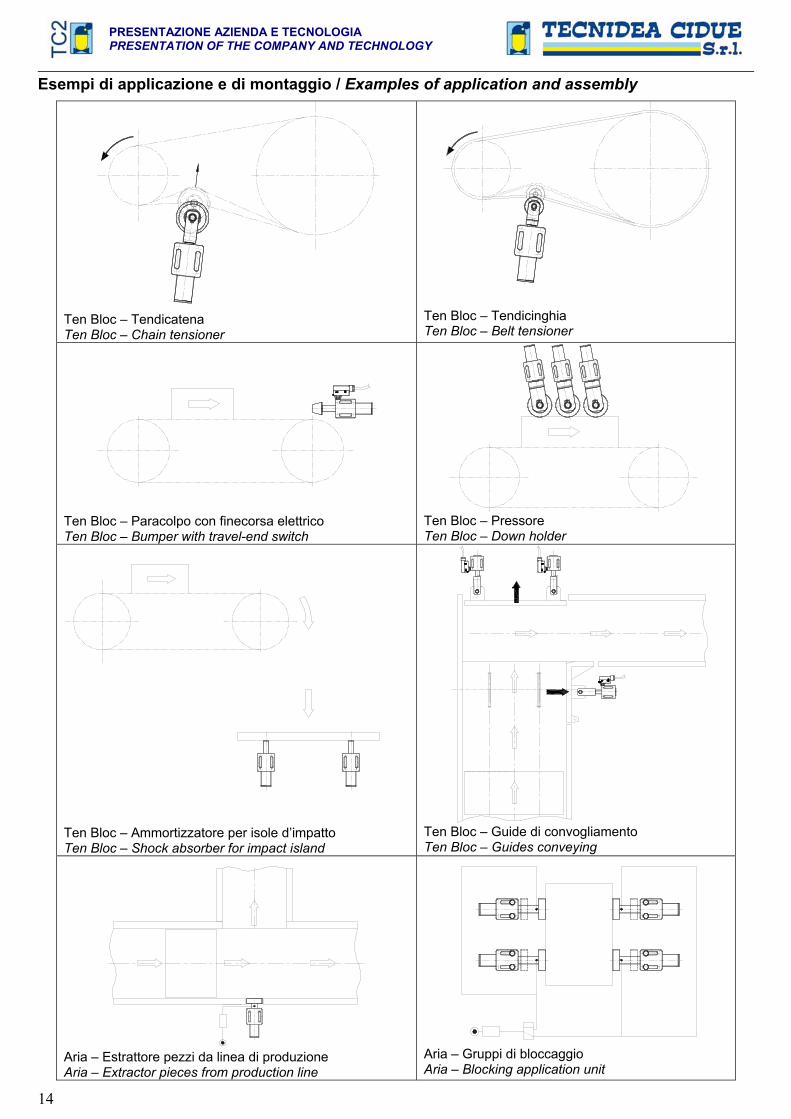
Esempi di applicazione e di montaggio / Examples of application and assembly
Ten Bloc – Tendicatena Ten Bloc – Chain tensioner
Ten Bloc – Tendicinghia Ten Bloc – Belt tensioner
Ten Bloc – Paracolpo con finecorsa elettrico Ten Bloc – Bumper with travel-end switch
Ten Bloc – Pressore Ten Bloc – Down holder
Ten Bloc – Ammortizzatore per isole d’impatto Ten Bloc – Shock absorber for impact island
Ten Bloc – Guide di convogliamento Ten Bloc – Guides conveying
Aria – Estrattore pezzi da linea di produzione Aria – Extractor pieces from production line
Aria – Gruppi di bloccaggio Aria – Blocking application unit

PRESENTAZIONE AZIENDA E TECNOLOGIA PRESENTATION OF THE COMPANY AND TECHNOLOGY
15
MANUALE DI CALCOLO TENDITORI AUTOMATICI ASSIALI
Catena a rulli Una trasmissione con catena a rulli è costituita da una ruota dentata motrice “A” ed una o più ruote condotte “B”. Il trasferimento di moto dalla ruota motrice alle ruote condotte avviene mediante un anello di catena. Lo sviluppo della lunghezza teorica “Lt” [mm] di una catena è dato dalla seguente formula:
pnLt
Schema di una trasmissione a catena
BA
I
Cm
T
fig 1
ADpA B p n ZAZBCmMt T
===========
ruota dentata motrice diametro primitivo ruota dentata A in mm ruota dentata condotta passo in mm numero di passi numero di denti della ruota A numero di denti della ruota B coppia motrice in Nm coppia da trasmettere in Nm tensione sulla catena sul ramo teso in N interasse in mm
Per le trasmissioni a catena risulta opportuno che ZA+ZB>50 e che il numero di denti su ogni ruota risulti ZA,B<125 poiché normalmente la catena ha un numero pari di maglie consigliamo ruote dentate con numeri di denti privi di divisori reciproci (se questo non fosse possibile conviene adottare almeno un pignone con un numero di denti dispari) in quanto con tale accorgimento l’usura si distribuisce uniformemente sia sui pignoni che sulla catena. A questo punto si può calcolare la lunghezza reale della catena:
YI4
)ZZ(p2
ZZp
I2L 2
2ABBA
r .
Dove Y è un numero in mm per il raggiungimento del numero pari di maglie.
Per la determinazione della tensione della catena a rulli è necessario ricavare la coppia motrice “Cm”, che è data dalla coppia da trasmettere “Mt” moltiplicata per un coefficiente “f=1,2 2,5”, dipendente dal numero di ripartenze, dalla potenza del motore e dalle condizioni di lavoro:
fMC tm .
Il tiro “T” della catena sul ramo teso sarà determinato secondo la formula:
1000DC2TpA
m .
Consigliamo quindi di scegliere una catena avente un carico di rottura da 5 a 8 volte superiore a T. Sul ramo condotto, invece, la tensione è circa nulla, infatti, l’unica forza agente è quella data dal peso proprio della catena. L’inconveniente più frequente con questo tipo di trasmissione è l’allungamento della catena e comporta:
- diminuzione dell’angolo di avvolgimento, quindi del numero di denti in presa sulla ruota motrice; - mancanza di costanza del rapporto di trasmissione; - anomalo contatto fra i rulli della catena ed i denti del pignone; - usura precoce delle catene e dei pignoni; - alta rumorosità;- vibrazioni, con propagazione delle stesse all’intera struttura della macchina; - salto del dente;- uscita della catena dalla trasmissione; - nei casi estremi rottura della catena.
Errato sarebbe, però, cercare di risolvere il problema dell’allentamento della catena tendendola eccessivamente durante la fase di messa in opera della trasmissione, in quanto dopo poco tempo si rischierebbe di accentuare le situazioni sopra descritte. Inevitabile risulta, quindi, la presenza di un Tendicatena Automatico che permetta di recuperare nel tempo gli allungamenti e di assorbire costantemente le vibrazioni. Il tendicatena automatico dovrà essere posizionato sul ramo
PRESENTAZIONE AZIENDA E TECNOLOGIAPRESENTATION OF THE COMPANY AND TECHNOLOGY
16
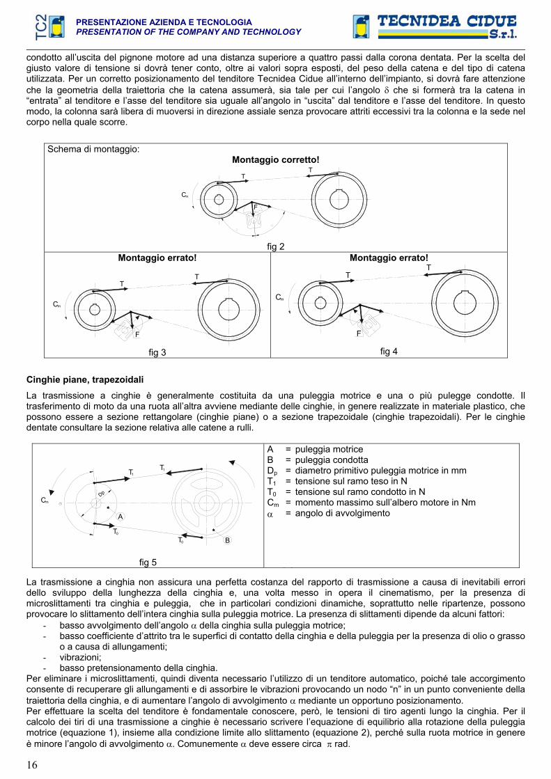
condotto all’uscita del pignone motore ad una distanza superiore a quattro passi dalla corona dentata. Per la scelta del giusto valore di tensione si dovrà tener conto, oltre ai valori sopra esposti, del peso della catena e del tipo di catena utilizzata. Per un corretto posizionamento del tenditore Tecnidea Cidue all’interno dell’impianto, si dovrà fare attenzione che la geometria della traiettoria che la catena assumerà, sia tale per cui l’angolo che si formerà tra la catena in “entrata” al tenditore e l’asse del tenditore sia uguale all’angolo in “uscita” dal tenditore e l’asse del tenditore. In questomodo, la colonna sarà libera di muoversi in direzione assiale senza provocare attriti eccessivi tra la colonna e la sede nel corpo nella quale scorre.
Schema di montaggio: Montaggio corretto!
Cm
F
TT
fig 2Montaggio errato!
Cm
F
TT
fig 3
Montaggio errato!
F
Cm
TT
fig 4
Cinghie piane, trapezoidali La trasmissione a cinghie è generalmente costituita da una puleggia motrice e una o più pulegge condotte. Il trasferimento di moto da una ruota all’altra avviene mediante delle cinghie, in genere realizzate in materiale plastico, che possono essere a sezione rettangolare (cinghie piane) o a sezione trapezoidale (cinghie trapezoidali). Per le cinghie dentate consultare la sezione relativa alle catene a rulli.
Dp
T0
A
T0 B
Cm
T1T1
fig 5
ABDpT1T0Cm
=======
puleggia motrice puleggia condotta diametro primitivo puleggia motrice in mm tensione sul ramo teso in N tensione sul ramo condotto in N momento massimo sull’albero motore in Nm angolo di avvolgimento
La trasmissione a cinghia non assicura una perfetta costanza del rapporto di trasmissione a causa di inevitabili errori dello sviluppo della lunghezza della cinghia e, una volta messo in opera il cinematismo, per la presenza di microslittamenti tra cinghia e puleggia, che in particolari condizioni dinamiche, soprattutto nelle ripartenze, possono provocare lo slittamento dell’intera cinghia sulla puleggia motrice. La presenza di slittamenti dipende da alcuni fattori:
- basso avvolgimento dell’angolo della cinghia sulla puleggia motrice; - basso coefficiente d’attrito tra le superfici di contatto della cinghia e della puleggia per la presenza di olio o grasso
o a causa di allungamenti; - vibrazioni; - basso pretensionamento della cinghia.
Per eliminare i microslittamenti, quindi diventa necessario l’utilizzo di un tenditore automatico, poiché tale accorgimento consente di recuperare gli allungamenti e di assorbire le vibrazioni provocando un nodo “n” in un punto conveniente della traiettoria della cinghia, e di aumentare l’angolo di avvolgimento mediante un opportuno posizionamento. Per effettuare la scelta del tenditore è fondamentale conoscere, però, le tensioni di tiro agenti lungo la cinghia. Per il calcolo dei tiri di una trasmissione a cinghie è necessario scrivere l’equazione di equilibrio alla rotazione della puleggia motrice (equazione 1), insieme alla condizione limite allo slittamento (equazione 2), perché sulla ruota motrice in genere è minore l’angolo di avvolgimento . Comunemente deve essere circa rad.
PRESENTAZIONE AZIENDA E TECNOLOGIA PRESENTATION OF THE COMPANY AND TECHNOLOGY
17
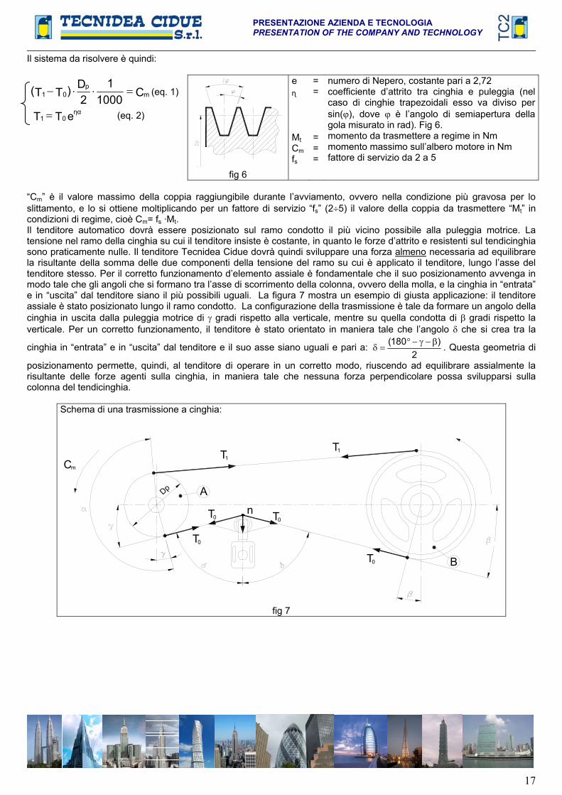
Il sistema da risolvere è quindi:
C10001
2D)TT( m
p01 (eq. 1)
eTT 01 (eq. 2)
fig 6
e
MtCmfs
==
===
numero di Nepero, costante pari a 2,72 coefficiente d’attrito tra cinghia e puleggia (nel caso di cinghie trapezoidali esso va diviso per sin( ), dove è l’angolo di semiapertura della gola misurato in rad). Fig 6. momento da trasmettere a regime in Nm momento massimo sull’albero motore in Nm fattore di servizio da 2 a 5
“Cm” è il valore massimo della coppia raggiungibile durante l’avviamento, ovvero nella condizione più gravosa per lo slittamento, e lo si ottiene moltiplicando per un fattore di servizio “fs” (2 5) il valore della coppia da trasmettere “Mt” in condizioni di regime, cioè Cm= fs ·Mt.Il tenditore automatico dovrà essere posizionato sul ramo condotto il più vicino possibile alla puleggia motrice. La tensione nel ramo della cinghia su cui il tenditore insiste è costante, in quanto le forze d’attrito e resistenti sul tendicinghia sono praticamente nulle. Il tenditore Tecnidea Cidue dovrà quindi sviluppare una forza almeno necessaria ad equilibrare la risultante della somma delle due componenti della tensione del ramo su cui è applicato il tenditore, lungo l’asse del tenditore stesso. Per il corretto funzionamento d’elemento assiale è fondamentale che il suo posizionamento avvenga in modo tale che gli angoli che si formano tra l’asse di scorrimento della colonna, ovvero della molla, e la cinghia in “entrata” e in “uscita” dal tenditore siano il più possibili uguali. La figura 7 mostra un esempio di giusta applicazione: il tenditore assiale è stato posizionato lungo il ramo condotto. La configurazione della trasmissione è tale da formare un angolo della cinghia in uscita dalla puleggia motrice di gradi rispetto alla verticale, mentre su quella condotta di gradi rispetto la verticale. Per un corretto funzionamento, il tenditore è stato orientato in maniera tale che l’angolo che si crea tra la
cinghia in “entrata” e in “uscita” dal tenditore e il suo asse siano uguali e pari a: 2
)180( . Questa geometria di
posizionamento permette, quindi, al tenditore di operare in un corretto modo, riuscendo ad equilibrare assialmente la risultante delle forze agenti sulla cinghia, in maniera tale che nessuna forza perpendicolare possa svilupparsi sulla colonna del tendicinghia.
Schema di una trasmissione a cinghia:
n
T0
Cm
Dp
T
A
0
T1
0T B
T
T0
1
fig 7
PRESENTAZIONE AZIENDA E TECNOLOGIAPRESENTATION OF THE COMPANY AND TECHNOLOGY
18
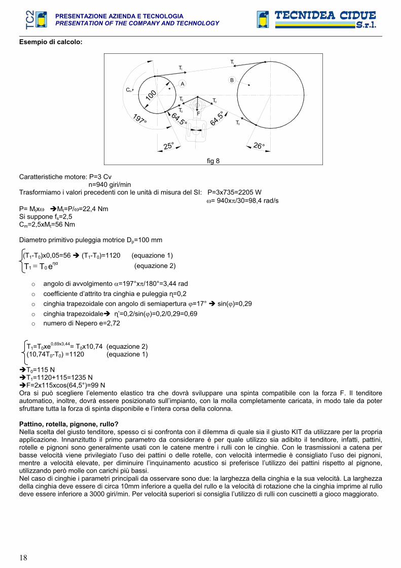
Esempio di calcolo:
25°
64.5°
100Cm
197°
26°
64.5°
T0 F
T0 T0
T0
A
T1
B
1T
fig 8
Caratteristiche motore: P=3 Cv n=940 giri/min Trasformiamo i valori precedenti con le unità di misura del SI: P=3x735=2205 W = 940x /30=98,4 rad/s P= Mtx Mt=P/ =22,4 Nm Si suppone fs=2,5 Cm=2,5xMt=56 Nm
Diametro primitivo puleggia motrice Dp=100 mm
(T1-T0)x0,05=56 (T1-T0)=1120 (equazione 1)
eTT 01 (equazione 2)
o angolo di avvolgimento =197°x /180°=3,44 rad o coefficiente d’attrito tra cinghia e puleggia =0,2 o cinghia trapezoidale con angolo di semiapertura =17° sin( )=0,29o cinghia trapezoidale ’=0,2/sin( )=0,2/0,29=0,69 o numero di Nepero e=2,72
T1=T0xe0,69x3,44= T0x10,74 (equazione 2) (10,74T0-T0) =1120 (equazione 1)
T0=115 N T1=1120+115=1235 N F=2x115xcos(64,5°)=99 N
Ora si può scegliere l’elemento elastico tra che dovrà sviluppare una spinta compatibile con la forza F. Il tenditore automatico, inoltre, dovrà essere posizionato sull’impianto, con la molla completamente caricata, in modo tale da poter sfruttare tutta la forza di spinta disponibile e l’intera corsa della colonna.
Pattino, rotella, pignone, rullo? Nella scelta del giusto tenditore, spesso ci si confronta con il dilemma di quale sia il giusto KIT da utilizzare per la propriaapplicazione. Innanzitutto il primo parametro da considerare è per quale utilizzo sia adibito il tenditore, infatti, pattini, rotelle e pignoni sono generalmente usati con le catene mentre i rulli con le cinghie. Con le trasmissioni a catena per basse velocità viene privilegiato l’uso dei pattini o delle rotelle, con velocità intermedie è consigliato l’uso dei pignoni, mentre a velocità elevate, per diminuire l’inquinamento acustico si preferisce l’utilizzo dei pattini rispetto al pignone, utilizzando però molle con carichi più bassi. Nel caso di cinghie i parametri principali da osservare sono due: la larghezza della cinghia e la sua velocità. La larghezza della cinghia deve essere di circa 10mm inferiore a quella del rullo e la velocità di rotazione che la cinghia imprime al rullodeve essere inferiore a 3000 giri/min. Per velocità superiori si consiglia l’utilizzo di rulli con cuscinetti a gioco maggiorato.

PRESENTAZIONE AZIENDA E TECNOLOGIA PRESENTATION OF THE COMPANY AND TECHNOLOGY
19
TENDITORI AUTOMATICI A ROTAZIONE Le catene a rulli (per trasmissione o per trasporto) e le cinghie fanno parte di quella serie di organi meccanici
chiamati elementi flessibili ad inviluppo che hanno come caratteristica in comune quella di reagire solamente a sollecitazioni di trazione. Questi organi meccanici vengono generalmente utilizzati per trasmettere potenza tra due mozzi rotanti, ma possono essere utilizzati anche per il trasporto o il sollevamento di oggetti. Per un corretto utilizzo degli elementi flessibili ad inviluppo è necessario prevedere, in fase di progettazione, un sistema per mantenere sempre in tensione queste unità durante il loro funzionamento. I tenditori automatici a rotazione presentano un punto di rotazione, detto fulcro, su cui il braccio del tenditore agisce andando a tendere la catena o la cinghia. L’usura delle superfici in contatto tra loro di una catena (perni, bussole, e rulli) durante il suo funzionamento, crea un maggior gioco e il relativo allungamento della catena, che quando è eccessivo può provocare: minor angolo di avvolgimento, mancanza di costanza del rapporto di trasmissione, anomalo contatto fra i rulli della catena ed i denti del pignone, usura precoce, alta rumorosità, vibrazioni, salto del dente, uscita della catena dalla trasmissione e nei casi estremi rottura della catena. Inevitabile risulta, quindi, equipaggiare la trasmissione di un tendicatena automatico, che permetta di recuperare gli allungamenti e assorbire costantemente le vibrazioni. I tendicatena automatici a rotazione devono essere posizionati sul tratto lento della trasmissione il più vicino possibile al pignone motore. Essi possono essere montati sia esternamente alla trasmissione (fig 9) sia internamente (fig 10) privilegiando se possibile il primo caso. I tenditori automatici a rotazione presentano un punto di rotazione, detto fulcro, su cui il braccio del tenditore agisce andando a tendere la catena o la cinghia. E’ estremamente importante che il tenditore venga posizionato in maniera tale che il suo fulcro non sia mai sulla direzione della retta d’applicazione della forza della catena (fig 12), così che non possa mai impuntarsi.
Schema di montaggio:
Cm
TT
fig 9 Montaggio corretto (Consigliato!)
Cm
TT
fig10Montaggio corretto
Cm
TT
fig 11 Montaggio corretto (Sconsigliato)
Cm
TT
FULCRO
fig 12 Montaggio errato
Nel caso di una trasmissione a doppio senso di marcia, dovrà essere posizionato un tenditore su entrambi i rami all’uscita dal pignone motore (fig 13). In questo caso si dovrà ad aver cura a posizionare i tendicatena in maniera tale che quando agiscono, alternativamente, sul ramo teso della trasmissione non dovranno oltrepassare l’angolo massimo di lavoro consentito dall’elemento elastico, dovuto all’allineamento della catena in fase di tiro. Nel caso in cui la trasmissione presenti un elevato interasse, spesso capita che un tenditore non abbia sufficiente corsa per recuperare tutto l’allungamento della catena, ma con un avvolgimento a “S” (fig 15 e 16), fattibile solamente con i tenditori a rotazione, è possibile riuscirci con un unico elemento elastico.
Cm
T
T
fig 13 Tensionamento per movimenti reversibili
mC
TT
fig 14 Tensionamento con tenditore interno

PRESENTAZIONE AZIENDA E TECNOLOGIAPRESENTATION OF THE COMPANY AND TECHNOLOGY
20
m
TT
fig 15 Tensionamento a “S” con ARCO
Cm
TT
fig 16 Tensionamento a “S” con ARCO speciale a doppia molla
In un tendicatena (o tendicinghia) il punto più “delicato” è il fulcro, ovvero il punto dove avviene la rotazione. In questa particolare zona, infatti, si manifestano gli attriti per sfregamento di particolari in contatto tra loro.
TmC
A
R1 R2
FN
N1
N2
Q90°
P3
fig 17
A = T = Cm=R1 =R2 =F = Q = N = N1 =N2 =P3 = = = 1/2 =
ruota dentata motrice tensione sul ramo teso coppia motrice ramo della catena in entrata nel tenditore ramo della catene in uscita dal tenditore fulcro o punto di rotazione forza sprigionata del tenditore forza di reazione della catena componente di N sul ramo R1componente di N sul ramo R2forza di compressione assiale della molla angolo di lavoro del tenditore angolo di posizionamento del tenditore angolo di entrata e uscita della catena dal tenditore
Un tenditore sprigiona una forza Q (fig 17) perpendicolare al braccio di rotazione che per reazione è equilibrata dalla catena con la forza N che si ripartisce con le forze di trazione N1 e N2 sui rami in entrata e uscita dal tendicatena rispettivamente R1 e R2. Quando si posiziona un tendicatena a rotazione bisogna far attenzione che le forze Q e N siano il più possibile sulla medesima direttrice in modo che non si sviluppino delle componenti tangenziali che vadano a scaricarsi sul fulcro. Ad ogni modo, nel caso del tenditore Arco, queste indesiderate forze tangenziali sono annullate dalla forza di compressione assiale P3 della molla. Il posizionamento del tenditore, quindi, dipende dall’angolo , ovvero l’angolo di lavoro dell’elemento elastico, e dall’angolo , ovvero l’angolo di posizionamento rispetto alla trasmissione. Il progettista dovrà quindi trovare il giusto rapporto tra questi parametri in funzione della geometria della propria trasmissione.
IIIII
Tm
A
R1R2
FP P2
P1
C
P3
fig 18
A = T = Cm=R1 = R2 = F = P = P1 = P2 = P3 =
ruota dentata motrice tensione sul ramo teso coppia motrice ramo della catena in entrata nel tenditore ramo della catene in uscita dal tenditore fulcro o punto di rotazione forza peso componente di P tangenziale componete di P normale forza di compressione assiale della molla
La figura 18 mostra l’influenza della forza peso P della catena sul tenditore in trasmissioni orizzontali. Il peso della catena, infatti, soprattutto nelle catene con un alto peso specifico per metro e con elevati interassi tra i pignoni della trasmissione, si scompone sul tendicatena con una forza P2 normale alla leva e una forza P1 tangenziale ad essa. Quest’ultima componente di compressione è bilanciata dalla forza assiale di compressione P3 della molla.

PRESENTAZIONE AZIENDA E TECNOLOGIA PRESENTATION OF THE COMPANY AND TECHNOLOGY
21
CALCULATION MANUAL
AUTOMATIC AXIAL TENSIONERSRoller ChainRoller chain gearings consist of a driving gear “A” and one or more driven gears “B”. The motion from the driving gear to the driven gears occurs by means of a chain link. The development of the theoretical length “Lt” [mm] is given by the following formula:
pnLt
Scheme of a transmission chain
BA
I
Cm
T
fig 1
ADpA B p n ZAZBCmMt T
===========
driving toothed wheeldiametral pitch of the toothed wheel A in mmdriven toothed wheelpitch in mmnumber of pitchesnumber of the teeth of the wheel Anumber of the teeth of the wheel Bmotor torque in Nmtorque to be transmitted in Nmpull on chain on the tensed branch in Ndistances between centres in mm
For chain gearings it would be better that ZA+ZB>50 and the number of spurs on each wheel is ZA,B<125 given the fact that a chain has a number of even links, we recommend that you use gears with spurs exempt from reciprocal dividers. When this not possible, at least one pinion with an odd number of spurs should be applied, as this contributes to obtain a uniform wear of both pinions and chain.
Now, the real length of the chain can be measured:
YI4
)ZZ(p2
ZZp
I2L 2
2ABBA
r
Where Y is a number in mm to obtain the even number of links.
The driving couple “Cm” must be obtained in order to determine the roller chain tension, and this is the result of the gearing couple “Mt” multiplied by a coefficient “f=1,2 2,5” which depends on the number of re-starts, the power of the motor and the working conditions:
fMC tm
The pull “T” of the chain on the tensed branch shall be determined using the following formula:
1000DC2TpA
m
We recommend that you use a chain with a breakage load 5 to 8 times higher than T. On the driven branch, the tension is almost zero because the only acting force is one given by the chain weight itself. With this type of gear, the most usual inconvenience is a loosening of the chain which causes:
- a decrease in the winding angle, i.e. the number of spurs acting on the driving gear; - lack of a steady gearing relation; - anomalous contact among the chain rollers and the pinion spurs; - early wear of both the chains and the pinions; - high level of noise;- vibrations that propagate to the overall structure of the machine; - spur jumping; - exit of the driving gear;- breakage of the chain in the worst of the cases.
It would be a mistake however, trying to solve the problem of a chain getting loose, by tensing it too much when you set it for operation because in a very short time the chain could get even looser.

PRESENTAZIONE AZIENDA E TECNOLOGIAPRESENTATION OF THE COMPANY AND TECHNOLOGY
22
As a consequence, the Automatic Chain Tensioner appears as the only solution to prevent any loosening and to absorb all vibrations. The automatic chain tensioner must be positioned on the driven branch to the exit of the motor pinion at a distance no shorter than 4 pitches from the gear. The ideal tension value must be selected on the basis of the above values, the weight of the chain and the type of chain used. The KIT table shows the reference values which you should consider to make the right choice. If you wish to position correctly the element inside your system, make sure that the the path geometry of the chain will be such that the angle obtained from the “incoming” chain to the tensioner and the tensioner axis is equal to the “outgoing” angle of the tensioner and the tensioner axis. This will allow the pin to move free in the axial direction without causing excessive friction between the pin and the inside of the body in which it slides.
Assembly scheme: Correct assembly!
Cm
F
TT
fig 2Wrong assembly!
Cm
F
TT
fig 3
Wrong assembly!
F
Cm
TT
fig 4
Flat or trapezoidal belts:
Belt drives mainly consist of a driving pulley and one or more driver pulleys. The belts are transmitting the motion from one gear to the other, and they are generally made in plastic materials, shaped in rectangular sections (flat belts) or trapezoidal sections (trapezoidal belts). For timing belts, see the section on roller chains.
Dp
T0
A
T0 B
Cm
T1T1
fig 5
ABDpT1T0Cm
=======
driving pulley driven pulleydiametral pitch of the driving pulley in mmtension on the tensed branch in Ntension on the driven branch in Nmaximum torque on the driving shaft in Nmangle of twist
Belt drives are not synonymous with perfect and steady gear relation because the micro-slidings between belt and pulley cannot be avoided along the length which moves kinematically. Above all in special dynamic conditions such as re-starts, the entire belt of the driving pulley may slide. Sliding depends on a number of factors:
- low winding of the angle of the belt on the driving pulley; - low friction coefficient between the contact surfaces of the belt and the pulley given the presence of oil or fat or
because of lengthening; - vibrations; - low pre-tensioning of the belt.
To avoid micro-sliding, the use of an automatic tensioner becomes a must and a way to recover any lengthening as well as vibrations with an “n” knot in a convenient position along the belt path. If appropriately placed, this also increases the winding angle .You can make the perfect selection of the tensioner if you know which are the pulling tensions acting along the belt. The calculation of the pulls of a belt drive depends necessarily on the equation of balance at the rotation of the driving pulley (equation 1) together with the max allowed sliding condition (equation 2), because on the driving gear the winding angle is usually lower. In general, must be approximately rad.
PRESENTAZIONE AZIENDA E TECNOLOGIA PRESENTATION OF THE COMPANY AND TECHNOLOGY
23
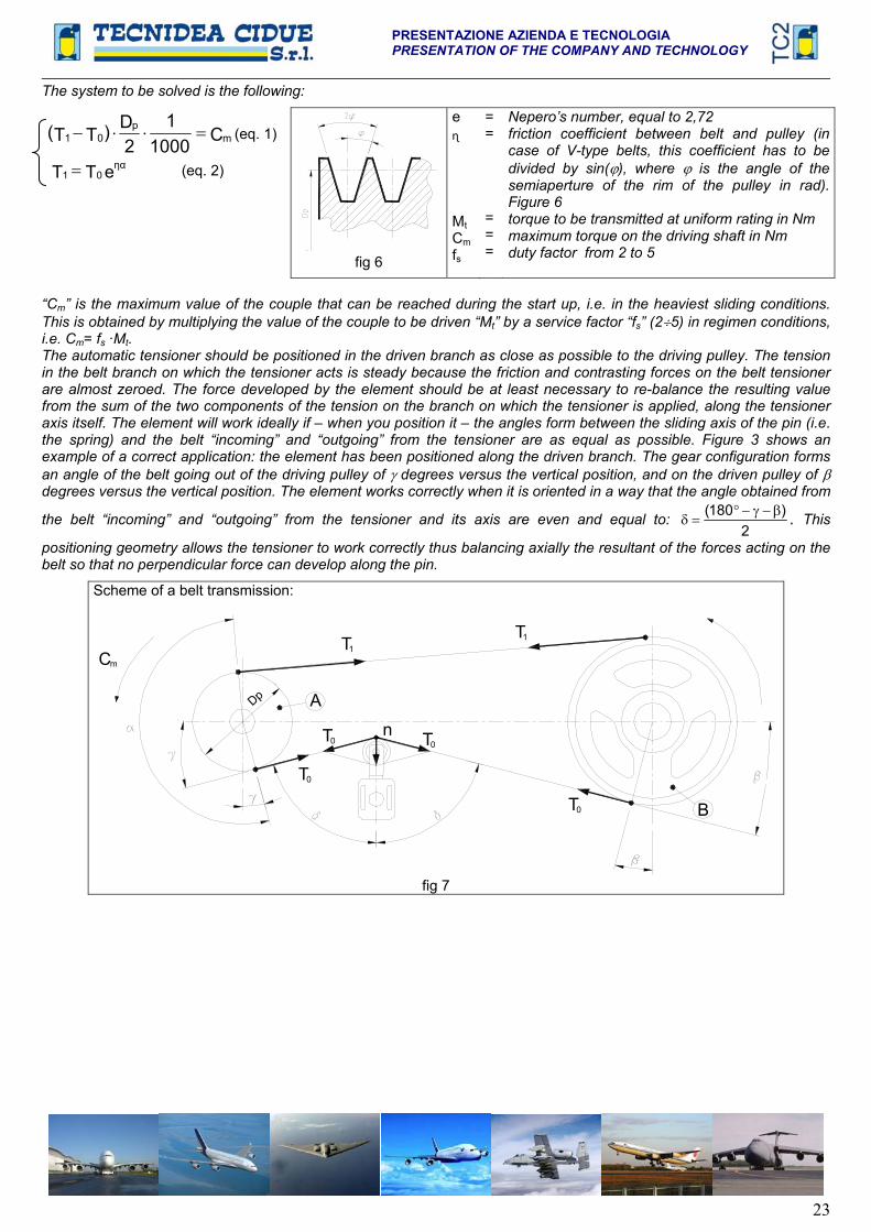
The system to be solved is the following:
C10001
2D)TT( m
p01 (eq. 1)
eTT 01 (eq. 2)
fig 6
e
MtCmfs
==
===
Nepero’s number, equal to 2,72 friction coefficient between belt and pulley (in case of V-type belts, this coefficient has to be divided by sin( ), where is the angle of the semiaperture of the rim of the pulley in rad). Figure 6 torque to be transmitted at uniform rating in Nmmaximum torque on the driving shaft in Nm duty factor from 2 to 5
“Cm” is the maximum value of the couple that can be reached during the start up, i.e. in the heaviest sliding conditions. This is obtained by multiplying the value of the couple to be driven “Mt” by a service factor “fs” (2 5) in regimen conditions, i.e. Cm= fs ·Mt.The automatic tensioner should be positioned in the driven branch as close as possible to the driving pulley. The tension in the belt branch on which the tensioner acts is steady because the friction and contrasting forces on the belt tensioner are almost zeroed. The force developed by the element should be at least necessary to re-balance the resulting value from the sum of the two components of the tension on the branch on which the tensioner is applied, along the tensioner axis itself. The element will work ideally if – when you position it – the angles form between the sliding axis of the pin (i.e.the spring) and the belt “incoming” and “outgoing” from the tensioner are as equal as possible. Figure 3 shows an example of a correct application: the element has been positioned along the driven branch. The gear configuration forms an angle of the belt going out of the driving pulley of degrees versus the vertical position, and on the driven pulley of degrees versus the vertical position. The element works correctly when it is oriented in a way that the angle obtained from
the belt “incoming” and “outgoing” from the tensioner and its axis are even and equal to:2
)180( . This
positioning geometry allows the tensioner to work correctly thus balancing axially the resultant of the forces acting on the belt so that no perpendicular force can develop along the pin.
Scheme of a belt transmission:
n
T0
Cm
Dp
T
A
0
T1
0T B
T
T0
1
fig 7
PRESENTAZIONE AZIENDA E TECNOLOGIAPRESENTATION OF THE COMPANY AND TECHNOLOGY
24
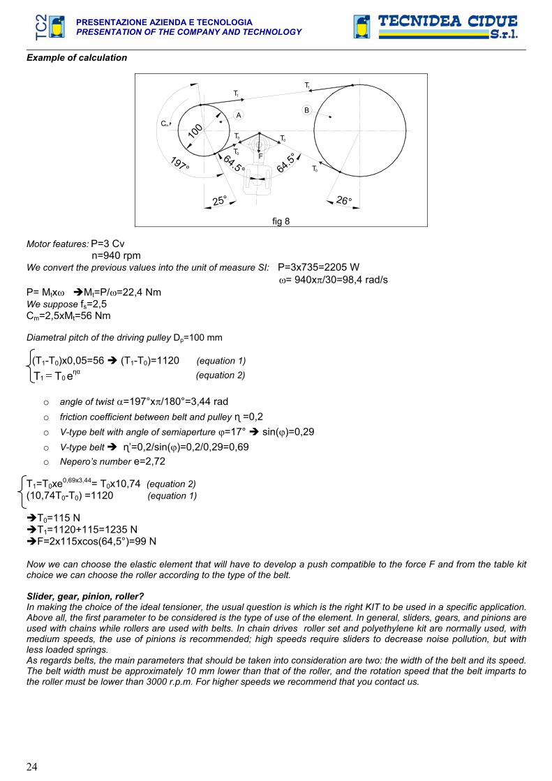
Example of calculation
25°
64.5°
100Cm
197°
26°
64.5°
T0 F
T0 T0
T0
A
T1
B
1T
fig 8
Motor features: P=3 Cv n=940 rpmWe convert the previous values into the unit of measure SI: P=3x735=2205 W = 940x /30=98,4 rad/s P= Mtx Mt=P/ =22,4 Nm We suppose fs=2,5Cm=2,5xMt=56 Nm
Diametral pitch of the driving pulley Dp=100 mm
(T1-T0)x0,05=56 (T1-T0)=1120 (equation 1)
eTT 01 (equation 2)
o angle of twist =197°x /180°=3,44 rad o friction coefficient between belt and pulley =0,2 o V-type belt with angle of semiaperture =17° sin( )=0,29o V-type belt ’=0,2/sin( )=0,2/0,29=0,69o Nepero’s number e=2,72
T1=T0xe0,69x3,44= T0x10,74 (equation 2)(10,74T0-T0) =1120 (equation 1)
T0=115 N T1=1120+115=1235 N F=2x115xcos(64,5°)=99 N
Now we can choose the elastic element that will have to develop a push compatible to the force F and from the table kit choice we can choose the roller according to the type of the belt.
Slider, gear, pinion, roller? In making the choice of the ideal tensioner, the usual question is which is the right KIT to be used in a specific application.Above all, the first parameter to be considered is the type of use of the element. In general, sliders, gears, and pinions are used with chains while rollers are used with belts. In chain drives roller set and polyethylene kit are normally used, with medium speeds, the use of pinions is recommended; high speeds require sliders to decrease noise pollution, but with less loaded springs. As regards belts, the main parameters that should be taken into consideration are two: the width of the belt and its speed. The belt width must be approximately 10 mm lower than that of the roller, and the rotation speed that the belt imparts to the roller must be lower than 3000 r.p.m. For higher speeds we recommend that you contact us.

PRESENTAZIONE AZIENDA E TECNOLOGIA PRESENTATION OF THE COMPANY AND TECHNOLOGY
25
AUTOMATIC ROTATION TENSIONERS Roller chains (for transmission or transport) and belts are part of the series of mechanical systems called
enveloping flexible elements which share the characteristic of reacting only to tensile stress. These mechanical parts are generally used to transmit power between two rotating hubs, but they may also be used to carry or lift objects. For a correct use of enveloping flexible elements it is necessary, in the design phase, to contemplate a system for keeping these units always taut during operation. Automatic rotation tensioners present a point of rotation, known as the fulcrum, on which the arm of the tensioner acts, thus tightening the chain or belt. The wear of the surfaces of a chain (pins, bushes and rollers) in contact with each other during operation creates a greater playand the relative stretching of the chain; when this is excessive it may cause a smaller winding angle, lack of constancy in thetransmission ratio, abnormal contact between the chain rollers and the teeth of the pinion, premature wear, high noise, vibrations, tooth skipping, escape of the chain from the transmission and, in extreme cases, breakage of the chain. It is therefore inevitable to equip the transmission with an automatic chain tensioner, which allows the recovery of stretching and constantly absorbs vibrations. Automatic rotation chain tensioners must be positioned on the loose part of the transmission, asclose as possible to the motor pinion. They may be fitted either on the outside of the transmission (fig 9) or on the inside (fig 10), preferably the former, if possible. Automatic rotation tensioners present a point of rotation, known as the fulcrum, on which the arm of the tensioner acts, thus tightening the chain or belt. It is extremely important to position the tensioner in such a way that its fulcrum is never in the direction of the line of application of the chain force (fig 12), so that it can never get stuck.
Assembly scheme:
Cm
TT
fig 9
Correct assembly (Recommended!)
Cm
TT
fig10
Correct assembly
Cm
TT
fig 11
Correct assembly (Not Recommended)
Cm
TT
FULCRO
fig 12
Wrong assembly!
With a transmission with double direction gears, you will have to put a tensioner on both the sections at the output of the driving pinion (figure 13). In this case you will have to take care to put the chain tensioners in a manner that when they work, alternatively, on the tight section of the transmission, they will not have to exceed the maximum working angle allowed by the elastic element, due by the alignment of the chain during the phase of tightening. When a transmission has an high distance between centers, often happens that a tensioner hasn’t enough stroke to recover all the stretch of the chain, but with an “S” winding (figure 15 and 16), that can be possible only with the rotationaltensioners, it is possible to do it with an only one elastic element.
Cm
T
T
fig 13 Tensioning for reversible movements
mC
TT
fig 14 Tensioning with internal tensioner
PRESENTAZIONE AZIENDA E TECNOLOGIAPRESENTATION OF THE COMPANY AND TECHNOLOGY
26
m
TT
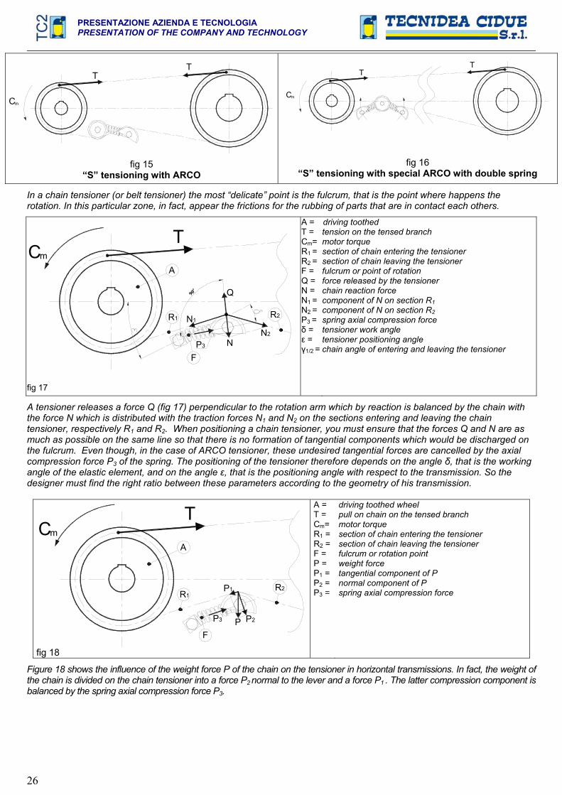
fig 15 “S” tensioning with ARCO
Cm
TT
fig 16 “S” tensioning with special ARCO with double spring
In a chain tensioner (or belt tensioner) the most “delicate” point is the fulcrum, that is the point where happens the rotation. In this particular zone, in fact, appear the frictions for the rubbing of parts that are in contact each others.
TmC
A
R1 R2
FN
N1
N2
Q90°
P3
fig 17
A = T = Cm=R1 =R2 =F = Q = N = N1 =N2 =P3 = = = 1/2 =
driving toothed tension on the tensed branch motor torque section of chain entering the tensioner section of chain leaving the tensioner fulcrum or point of rotation force released by the tensioner chain reaction force component of N on section R1component of N on section R2spring axial compression force tensioner work angle tensioner positioning angle chain angle of entering and leaving the tensioner
A tensioner releases a force Q (fig 17) perpendicular to the rotation arm which by reaction is balanced by the chain with the force N which is distributed with the traction forces N1 and N2 on the sections entering and leaving the chain tensioner, respectively R1 and R2. When positioning a chain tensioner, you must ensure that the forces Q and N are as much as possible on the same line so that there is no formation of tangential components which would be discharged on the fulcrum. Even though, in the case of ARCO tensioner, these undesired tangential forces are cancelled by the axial compression force P3 of the spring. The positioning of the tensioner therefore depends on the angle , that is the working angle of the elastic element, and on the angle , that is the positioning angle with respect to the transmission. So the designer must find the right ratio between these parameters according to the geometry of his transmission.
Tm
A
R1R2
FP P2
P1
C
P3
fig 18
A = T = Cm=R1 = R2 = F = P = P1 = P2 = P3 =
driving toothed wheel pull on chain on the tensed branch motor torque section of chain entering the tensioner section of chain leaving the tensioner fulcrum or rotation point weight force tangential component of P normal component of P spring axial compression force
Figure 18 shows the influence of the weight force P of the chain on the tensioner in horizontal transmissions. In fact, the weight of the chain is divided on the chain tensioner into a force P2 normal to the lever and a force P1 . The latter compression component is balanced by the spring axial compression force P3.

TEN BLOC
27
BREVETTATO – PATENDED
C 2013
TEN BLOC
28
TEN BLOC – Brevettato ELEMENTO ELASTICO ASSIALE A MOLLA – TENDICATENA AUTOMATICO – TENDICINGHIA AUTOMATICO BLOCCO DI TENSIONE – GRUPPO DI PRESSIONE – AMMORTIZZATORE
Principali caratteristiche: Modulare, una colonna – una molla, due viti per il fissaggio, Robusto, Struttura in metallo, alluminio ed acciaio. Possibili componenti in acciaio inox, Bassi ed Alti carichi sviluppati, Testa rotante o fissa, Precarica,Antirotazione, Unidirezionale, Finecorsa elettrico per il controllo, Basse ed Alte temperature di lavoro, Ammortizzatore, Gruppo di pressione, Supporti di rinvio per trasmissioni e per trasportatori, Tenditore Manuale.
TEN BLOC è un elemento elastico assiale a molla progettato per soddisfare le più ampie esigenze del mercato: tendicatena automatico, tendicinghia automatico, tenditore automatico di gruppi di rinvio di nastri o trasportatori, ammortizzatore, gruppo di pressione ecc. TEN BLOC è costituito da un corpo scatolare in alluminio pressofuso da cui esce una colonna in acciaio spinta da una molla meccanica. La colonna scorre all’interno di una bronzina alloggiata nel corpo. Sulla colonna è possibile applicare molteplici kit d’interfaccia: pattini in polietilene (tipo V ed L), rotelle in polietilene su forcella (tipo RF), pignoni su forcella(tipo RR), e rulli in acciaio zincato su forcella (tipo RAU) o rulli in poliammide su forcella (tipo RAP). TEN BLOC può essere dotato di sistema di precarica (TB), di sistema di unidirezionale (TBB), di sistema di antirotazione (TBA). Il corpo scatolare può, inoltre, essere munito di un finecorsa elettrico che permette di verificare in ogni istante il corretto funzionamento della macchina e in caso di eccessivi allungamenti o di rottura della catena attivare un segnale acustico, luminoso o bloccare l’impianto se necessario. Nella gamma di prodotti TEN BLOC sono presenti, inoltre, gli elementi di pressione DECA, che normalmente sono impiegati per creare dei gruppi di spinta per alberi condotti di nastri o trasportatori. I DECA possono essere utilizzati anche come ammortizzatori e deceleratori. Con i DECA è possibile ottenere forze di spinta e corse diverse in funzione delle proprie esigenze. Con la gamma di prodotti TEN BLOC è possibile eseguire esecuzioni speciali a richiesta quali elementi con doppia guida di scorrimento (TBCU) ed elementi con azione in tiro (TBt). TEN BLOC si distingue, inoltre, per la sua modularità, in quanto unendo opportunamente i vari elementi che costituisco l’elemento base (colonne, cilindri, tappi, molle, unioni e corpi) è possibile realizzare prodotti personalizzati adattabili alle proprie necessità.
TEN BLOC – Patented AXIAL ELASTIC ELEMENT – AUTOMATIC CHAIN TENSIONER – AUTOMATIC BELT TENSIONER - TENSION BLOCK DOWN HOLDERS – SHOCK ABSORBER
Main features: Modular, one column-one spring, two screws for the fixing, Strong - structure made of metal, aluminium, steel - possible components made of stainless steel - low and high generated loads - fixed or rotating head – preloading – anti-rotation – one-directional - travel-end switch for checking – low and high operating temperatures – shock absorber – pressure application – return supports for transmissions and conveyors – manual tensioner.
TEN BLOC is an automatic axial chain or belt tensioner designed to satisfy the widest market-needs: automatic chain tensioner device, automatic belt tensioner device, automatic tensioner of driven shaft of chain or belt conveyors, bumper, pressure units etc. TEN BLOC consists of a steel column thrusted by a mechanical spring connected to a box-shaped body made of die-cast aluminium. The column slides inside a bronze ring lodged inside the body. It is possible to mount different types of interface kits on the top of the column: polyethylene sliding blocks (type V and L), polyethylene wheels on fork (type RF), pinions on fork (type RR) and zinc plated steel rollers on fork (RAU) or polyamide rollers on fork (RAP). TEN BLOC can be provided with a preloading system (TB), with a one-directional system (TBB) or with an anti-rotation system (TBA). The box-shaped body can, furthermore, be equipped with an electric travel-end switch that allows to check whether the machine works properly at every moment. In case of excessive chain lengthening or chain breaking the same device activates an acoustic or light signal or, if necessary, stops the plant. Also part of the TEN BLOC product range are the DECA pressure units for driven shaft of belt or chain conveyor. DECA can also be used as shock absorbers and decelerators. With DECAs one can obtain different forces of thrust and different travels according to one’s actual needs. The entire TEN BLOC product range makes it possible, on request, to perform special executions such as elements with double slide guide (TBCU) or elements functioning in drag conditions (TBt). TEN BLOC furthermore distinguishes itself for its modularity as it aptly joins several base elements (columns, cylinders, plugs, springs, junctions and bodies) thus enabling one to produce user-defined products which will suit individual needs.

TEN BLOC
29
PANORAMICA PRODOTTI: / PRODUCT RANGE: “BREVETTATO-PATENTED”
TN pag.36 TNa pag.36
TB pag.37 TBa pag.37
TBB pag.38 TBA pag.39 TBAB pag.40 TF pag.43
TBP pag.31 TB FCE pag.34 TBCU pag.34 TBt pag.35
DECA pag.41 DECA Pr pag.41 DECA Un pag.42 2TB pag.43
TEN
BLO
C –
TE
N B
LOC

TEN BLOC
30
PANORAMICA PRODOTTI: / PRODUCT RANGE: “BREVETTATO-PATENTED”
TB 80 A pag.44 TB 80 F pag.44 TENC pag.46 TENB pag.47
V80 pag.45 V pag.49 L pag.50 RF pag.51
RR pag.52 RU pag.53 RP pag.53 2V pag.55
2RR pag.56 2RAU pag.57 2RAP pag.57 BT /UT pag.64-66
LT pag.65 BRR pag.67 F pag.58 Accessories pag.58-59-60-61
TEN BLOC
31
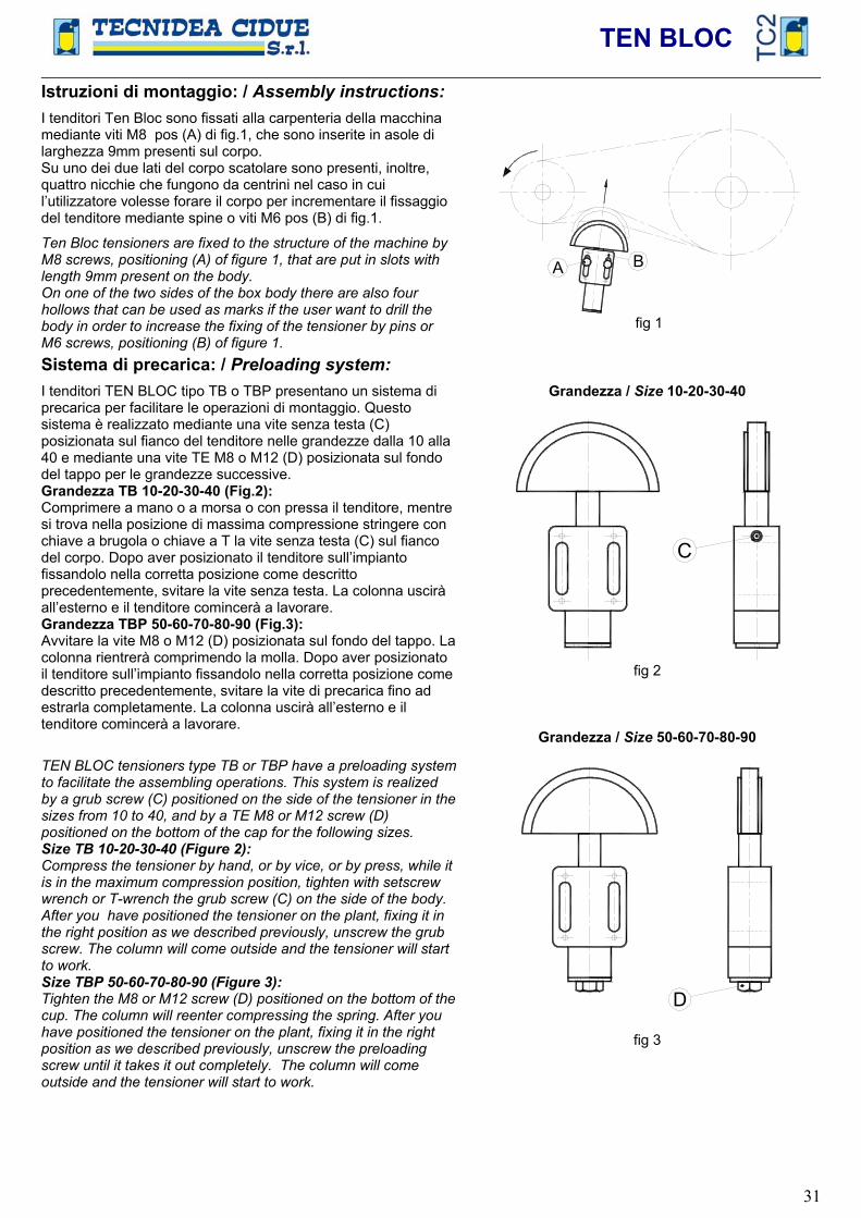
Istruzioni di montaggio: / Assembly instructions:I tenditori Ten Bloc sono fissati alla carpenteria della macchina mediante viti M8 pos (A) di fig.1, che sono inserite in asole di larghezza 9mm presenti sul corpo. Su uno dei due lati del corpo scatolare sono presenti, inoltre, quattro nicchie che fungono da centrini nel caso in cui l’utilizzatore volesse forare il corpo per incrementare il fissaggio del tenditore mediante spine o viti M6 pos (B) di fig.1.
Ten Bloc tensioners are fixed to the structure of the machine by M8 screws, positioning (A) of figure 1, that are put in slots with length 9mm present on the body. On one of the two sides of the box body there are also four hollows that can be used as marks if the user want to drill the body in order to increase the fixing of the tensioner by pins or M6 screws, positioning (B) of figure 1.
A B
fig 1
Sistema di precarica: / Preloading system:I tenditori TEN BLOC tipo TB o TBP presentano un sistema di precarica per facilitare le operazioni di montaggio. Questo sistema è realizzato mediante una vite senza testa (C) posizionata sul fianco del tenditore nelle grandezze dalla 10 alla 40 e mediante una vite TE M8 o M12 (D) posizionata sul fondo del tappo per le grandezze successive. Grandezza TB 10-20-30-40 (Fig.2): Comprimere a mano o a morsa o con pressa il tenditore, mentre si trova nella posizione di massima compressione stringere con chiave a brugola o chiave a T la vite senza testa (C) sul fianco del corpo. Dopo aver posizionato il tenditore sull’impianto fissandolo nella corretta posizione come descritto precedentemente, svitare la vite senza testa. La colonna uscirà all’esterno e il tenditore comincerà a lavorare. Grandezza TBP 50-60-70-80-90 (Fig.3): Avvitare la vite M8 o M12 (D) posizionata sul fondo del tappo. La colonna rientrerà comprimendo la molla. Dopo aver posizionato il tenditore sull’impianto fissandolo nella corretta posizione come descritto precedentemente, svitare la vite di precarica fino ad estrarla completamente. La colonna uscirà all’esterno e il tenditore comincerà a lavorare.
TEN BLOC tensioners type TB or TBP have a preloading system to facilitate the assembling operations. This system is realized by a grub screw (C) positioned on the side of the tensioner in the sizes from 10 to 40, and by a TE M8 or M12 screw (D) positioned on the bottom of the cap for the following sizes. Size TB 10-20-30-40 (Figure 2): Compress the tensioner by hand, or by vice, or by press, while it is in the maximum compression position, tighten with setscrew wrench or T-wrench the grub screw (C) on the side of the body. After you have positioned the tensioner on the plant, fixing it in the right position as we described previously, unscrew the grub screw. The column will come outside and the tensioner will start to work. Size TBP 50-60-70-80-90 (Figure 3): Tighten the M8 or M12 screw (D) positioned on the bottom of the cup. The column will reenter compressing the spring. After you have positioned the tensioner on the plant, fixing it in the right position as we described previously, unscrew the preloading screw until it takes it out completely. The column will come outside and the tensioner will start to work.
Grandezza / Size 10-20-30-40
C
fig 2
Grandezza / Size 50-60-70-80-90
D
fig 3
TEN BLOC
32
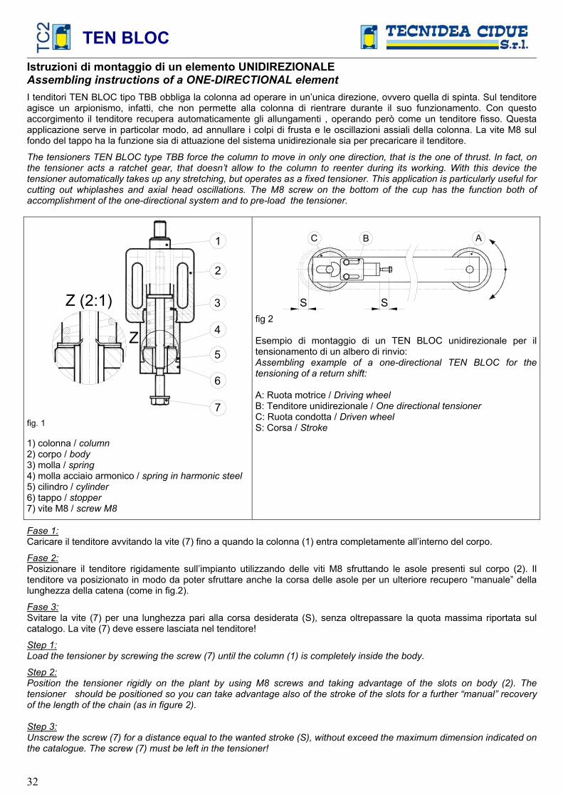
Istruzioni di montaggio di un elemento UNIDIREZIONALEAssembling instructions of a ONE-DIRECTIONAL element I tenditori TEN BLOC tipo TBB obbliga la colonna ad operare in un’unica direzione, ovvero quella di spinta. Sul tenditore agisce un arpionismo, infatti, che non permette alla colonna di rientrare durante il suo funzionamento. Con questo accorgimento il tenditore recupera automaticamente gli allungamenti , operando però come un tenditore fisso. Questa applicazione serve in particolar modo, ad annullare i colpi di frusta e le oscillazioni assiali della colonna. La vite M8 sul fondo del tappo ha la funzione sia di attuazione del sistema unidirezionale sia per precaricare il tenditore.
The tensioners TEN BLOC type TBB force the column to move in only one direction, that is the one of thrust. In fact, on the tensioner acts a ratchet gear, that doesn’t allow to the column to reenter during its working. With this device the tensioner automatically takes up any stretching, but operates as a fixed tensioner. This application is particularly useful forcutting out whiplashes and axial head oscillations. The M8 screw on the bottom of the cup has the function both of accomplishment of the one-directional system and to pre-load the tensioner.
5
7
6
Z (2:1)
Z 4
3
2
1
fig. 1
1) colonna / column2) corpo / body3) molla / spring4) molla acciaio armonico / spring in harmonic steel5) cilindro / cylinder6) tappo / stopper7) vite M8 / screw M8
S
C
S
AB
fig 2
Esempio di montaggio di un TEN BLOC unidirezionale per il tensionamento di un albero di rinvio: Assembling example of a one-directional TEN BLOC for the tensioning of a return shift:
A: Ruota motrice / Driving wheel B: Tenditore unidirezionale / One directional tensionerC: Ruota condotta / Driven wheelS: Corsa / Stroke
Fase 1:Caricare il tenditore avvitando la vite (7) fino a quando la colonna (1) entra completamente all’interno del corpo.
Fase 2:Posizionare il tenditore rigidamente sull’impianto utilizzando delle viti M8 sfruttando le asole presenti sul corpo (2). Il tenditore va posizionato in modo da poter sfruttare anche la corsa delle asole per un ulteriore recupero “manuale” della lunghezza della catena (come in fig.2).
Fase 3:Svitare la vite (7) per una lunghezza pari alla corsa desiderata (S), senza oltrepassare la quota massima riportata sul catalogo. La vite (7) deve essere lasciata nel tenditore!
Step 1:Load the tensioner by screwing the screw (7) until the column (1) is completely inside the body.
Step 2:Position the tensioner rigidly on the plant by using M8 screws and taking advantage of the slots on body (2). The tensioner should be positioned so you can take advantage also of the stroke of the slots for a further “manual” recovery of the length of the chain (as in figure 2).
Step 3:Unscrew the screw (7) for a distance equal to the wanted stroke (S), without exceed the maximum dimension indicated on the catalogue. The screw (7) must be left in the tensioner!

TEN BLOC
33
Sistema antirotazione: / Anti-Rotation system:I tenditori TEN BLOC hanno la possibilità di essere provvisti di un sistema antirotazionale della colonna intorno al proprio asse in maniera tale da impedire la rotazione del kit montato sul tenditore. Tale soluzione elimina le vibrazioni radiali della testa, la sua applicazione è particolarmente indicata per le trasmissioni ad elevate velocità (v>20 m/min) ed in tutti quei casi dove la catena sia soggetta a forti oscillazioni. Il sistema antirotazione è particolarmente indicato nell’utilizzo di elementi per il tensionamento di cinghie, in quanto questo sistema permette al rullo tendicinghia di lavorare sempre nella corretta posizione. Il sistema antirotazione inoltre è indicato quando l’elemento tenditore viene utilizzato per realizzare l’intero gruppo di rinvio, soprattutto con interassi di trasmissione lunghi. L’antirotazione viene eseguita in due versioni: - Versione “a” (Fig. 2):
Prevede l’utilizzo di una rondella a sezione quadra che va ad impedire completamente la rotazione della colonna, ha il vantaggio di essere una soluzione semplice ed economica. La figura 2 indica la differenza di costruzione tra un elemento antirotazione “TBa” e un elemento “TN” o “TB” (Fig.1) in cui la colonna ha la possibilità di ruotare sul proprio asse. Nell’elemento “TBa” la rotazione è impedita da una rondella a sezione quadrata posizionata ll’interno del corpo scatolare in alluminio anch’esso a sezione quadrata. Negli elementi “TN” o “TB”, invece, viene utilizzata una rondella a sezione tonda.
- Versione “A” (Fig. 3): Prevede l’utilizzo di un kit esterno al tenditore. In questo caso la colonna è orientabile, in modo da consentirne l’allineamento con la catena/cinghia, ed in un secondo momento è possibile bloccarne la possibilità di rotazione per mezzo della vite (F).
TEN BLOC tensioners can to be provided with an anti-rotation system of the column around its own axis in order to prevent the rotation of the kit assembled on the tensioner. This solution eliminates the radial head vibrations, it is particularly useful for the transmissions where are involved high speeds (v>20 m/min) and in all operations where the chain is subjected to strong oscillations. The anti-rotation system is particularly useful in the use of elements for the tensioning of belts, since this system allows to the roller belt tensioner to work always in the right position. Moreover it is useful when the tensioner element is used to realize all the return unit, above all with long distances between centers. The anti-rotation is made in two versions: - Version “a” (Figure 2):
It considers the use of a washer with square section that it prevent completely the rotation of the column, its advantage is to be an easy and cheap solution. The picture 2 shows the difference of construction between a “TBa” anti-rotation element and a “TN” or “TB” element (figure 1) where the column has the possibility to rotate on its own axis. In the “TBa” element the rotation is prevented by a washer with square section positioned in the alluminium box body, that has square section too. In the “TN” or “TB” elements, instead, is used a washer with round section.
- Version “A” (Figure 3): It considers the use of a kit external to the tensioner. In this case the column is revolving, in order to allow the alignment with the chain/belt, and in a second moment it is possible to stop by a screw (F) the possibility of rotation.
Versione base per tipi TN o TB: Basic version for types TN or TB:
A
360°
A-A
fig 1
Versione “a” / Version “a”:
A
A-A
fig 2
Versione “A” / Version “A”:
F
fig 3

TEN BLOC
34
FINECORSA ELETTRICO tipo: "E" / TRAVEL-END SWITCH type: "E"
(42)
(67)
Gli elementi elastici a molla TEN BLOC, possono essere forniti a richiesta con finecorsa elettrico “E”. Le applicazioni con FCE sono molte in quanto consentono di controllare e di verificare il corretto funzionamento delle macchine, ma anche di ricevere o di dare dei segnali di comando per l’espletamento di funzioni meccaniche. Questo sistema è particolarmente utile quando si voglia garantire l’integrità della macchina e/o salvaguardare l’incolumità degli operatori.
The elastic spring elements TEN BLOC can be supplied, on demand, with travel-end switch “E”. The applications with FCE are various, since they allow to check and to prove the correct functioning of the machine, but also to receive or to give control signals for the carrying out of the mechanical functions. This system is particularly useful when you want to grant the integrity of the machine and/or where the workers’ safety must be protected.
Schema elettrico: / Electrical diagram:
R
R
R
R
R
R
M
DOPPIA GUIDA tipo: "TBCU" / DOUBLE SLIDE type: "TBCU"
L’esecuzione a doppia guida TBCU, grazie al doppio supporto della colonna sia sul corpo che nel tappo terminale, riduce sensibilmente i giochi di accoppiamento dovuti all’usura di funzionamento garantendo una maggior stabilità dello stelo in uscita. Questa soluzione è particolarmente indicata laddove ci siano applicazioni con corsa elevata (maggiore di 60mm) e con carichi trasversali all’asse della colonna. Per i dati tecnici di questo prodotto vi invitiamo a consultare il nostro ufficio tecnico.
The execution with double slide TBCU, thanks to the double support of the column, both on the body and on the final cap, reduces significantly the coupling clearances due by the functioning wear, granting an higher stability of the rod in output. This solution is particularly useful for the applications with high travel (bigger than 60mm) and with loads trasverse to the axis of the column. For the technical specifications of this product, we suggest you to contact our technical department.
.

TEN BLOC
35
TENDICATENA IN "TIRO" tipo: "TBt" / CHAIN TIGHTENER IN “DRAG CONDITION” type: "TBt"
L’elemento elastico TBt consente di soddisfare tutte le richieste che prevedono applicazioni in tiro anziché in spinta, sia per scelte di funzionamento che per necessità di montaggio. Con questa applicazione la catena sarà quindi tirata anziché spinta come per le esecuzione standard. Per i dati tecnici di questo prodotto vi chiediamo di consultare il nostro ufficio tecnico.
The elastic element TBt allows to comply with the inquiries that consider applications in “drag condition” instead of in “thrust”, both for choices of functioning and for assembly necessity. With this application the chain will be therefore stretched instead of pushed, as for the standard executions. For the technical specifications of this product, we suggest you to contact our technical department.
Foto applicazione / Application photos
01 02 03
04 05 06
07 08 09 10
TEN BLOC
36
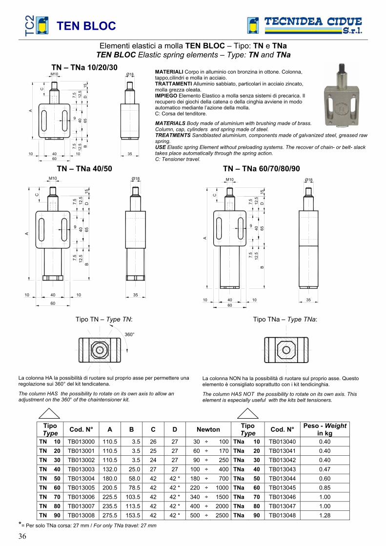
Elementi elastici a molla TEN BLOC – Tipo: TN e TNaTEN BLOC Elastic spring elements – Type: TN and TNa
TN – TNa 10/20/30
60 40 10 10
7.5
7.5
65D
A
35
12.5
12
.5
40
Ø18 M10
C
9
B15
MATERIALI Corpo in alluminio con bronzina in ottone. Colonna, tappo,cilindri e molla in acciaio. TRATTAMENTI Alluminio sabbiato, particolari in acciaio zincato, molla grezza oleata. IMPIEGO Elemento Elastico a molla senza sistemi di precarica. Il recupero dei giochi della catena o della cinghia avviene in modo automatico mediante l’azione della molla. C: Corsa del tenditore.
MATERIALS Body made of aluminium with brushing made of brass. Column, cap, cylinders and spring made of steel. TREATMENTS Sandblasted aluminium, components made of galvanized steel, greased raw spring.USE Elastic spring Element without preloading systems. The recover of chain- or belt- slack takes place automatically through the spring action. C: Tensioner travel.
TN – TNa 40/50
60
4010 10
7.5
7.5
65
D
A
35
B12
.5
12.5
40
C 15
9
TN – TNa 60/70/80/90
60 40 10 10
7.5
7.5
65D
A
35
B12
.5
12.5
40
Ø18 M10
C 15
9
Tipo TN – Type TN:
360°
La colonna HA la possibilità di ruotare sul proprio asse per permettere una regolazione sui 360° del kit tendicatena.
The column HAS the possibility to rotate on its own axis to allow an adjustment on the 360° of the chaintensioner kit.
Tipo TNa – Type TNa:
La colonna NON ha la possibilità di ruotare sul proprio asse. Questo elemento è consigliato soprattutto con i kit tendicinghia.
The column HAS NOT the possibility to rotate on its own axis. This element is especially useful with the kits belt tensioners.
TipoType Cod. N° A B C D Newton Tipo
Type Cod. N° Peso - Weightin kg
TN 10 TB013000 110.5 3.5 26 27 30 ÷ 100 TNa 10 TB013040 0.40 TN 20 TB013001 110.5 3.5 25 27 60 ÷ 170 TNa 20 TB013041 0.40 TN 30 TB013002 110.5 3.5 24 27 90 ÷ 250 TNa 30 TB013042 0.40 TN 40 TB013003 132.0 25.0 27 27 100 ÷ 400 TNa 40 TB013043 0.47 TN 50 TB013004 180.0 58.0 42 42 * 180 ÷ 700 TNa 50 TB013044 0.60 TN 60 TB013005 200.5 78.5 42 42 * 220 ÷ 1000 TNa 60 TB013045 0.85 TN 70 TB013006 225.5 103.5 42 42 * 340 ÷ 1500 TNa 70 TB013046 1.00 TN 80 TB013007 235.5 113.5 42 42 * 400 ÷ 2000 TNa 80 TB013047 1.00 TN 90 TB013008 275.5 153.5 42 42 * 500 ÷ 2500 TNa 90 TB013048 1.28
*= Per solo TNa corsa: 27 mm / For only TNa travel: 27 mm

TEN BLOC
37
Elementi elastici a molla TEN BLOC – Tipo: TB e TBa TEN BLOC Elastic spring elements – Tipo: TB and TBa
TB – TBa 10/20/30
60 40 10 10
7.5
7.5
65D
A
35
12.5
12.5
40
M8
C
9
B15
MATERIALI Corpo in alluminio con bronzina in ottone. Colonna, tappo,cilindri, viti e molla in acciaio. TRATTAMENTI Alluminio sabbiato, particolari in acciaio zincato, molla grezza oleata. IMPIEGO Elemento Elastico a molla con sistema di precarica. Il recupero dei giochi della catena o della cinghia avviene in modo automatico mediante l’azione della molla. C: Corsa del tenditore.
MATERIALS Body made of aluminium with brushing made of brass. Column, cap, cylinders, screws and spring made of steel.TREATMENTS Sandblasted aluminium, components made of galvanized steel, greased raw spring.USE Elastic spring Element with preloading system. The recover of chain- or belt- slack takes place automatically through the spring action. C: Tensioner travel.
TB – TBa 40 / TBP 50
60
4010 10
7.5
7.5
65
D
A
35
B12
.5
12.5
40
Ø18
M8
Type TB 40
Type TBP 50
Type TBa 40
C
9
15
TBP 60/70/80/90
60 4010 10
7.5
7.5
65
D
A
35
B12
.5
12.5
40
Ø18
C9
15
Tipo TB – Type TB:
360°
La colonna HA la possibilità di ruotare sul proprio asse per permettere una regolazione sui 360° del kit tendicatena.
The column HAS the possibility to rotate on its own axis to allow an adjustment on the 360° of the chaintensioner kit.
Tipo TBa – Type TBa:
La colonna NON ha la possibilità di ruotare sul proprio asse. Questo elemento è consigliato soprattutto con i kit tendicinghia.
The column HAS NOT the possibility to rotate on its own axis. This element is especially useful with the belt tensioners.
TipoType Cod. N° A B C D Newton Tipo
Type Cod. N° Peso - Weightin kg
TB 10 TB013020 110.5 3.5 26 27 30 ÷ 100 TBa 10 TB013060 0.40 TB 20 TB013021 110.5 3.5 25 27 60 ÷ 170 TBa 20 TB013061 0.40 TB 30 TB013022 110.5 3.5 24 27 90 ÷ 250 TBa 30 TB013062 0.40 TB 40 TB013023 132.0 25.0 27 27 100 ÷ 400 TBa 40 TB013063 0.47 TBP 50 TB013024 180.0 58.0 42 42 180 ÷ 700 0.60 TBP 60 TB013025 200.5 78.5 42 42 220 ÷ 1000 0.85 TBP 70 TB013026 225.5 103.5 42 42 340 ÷ 1500 1.00 TBP 80 TB013027 235.5 113.5 42 42 400 ÷ 2000 1.00 TBP 90 TB013028 275.5 153.5 42 42 500 ÷ 2500 1.28
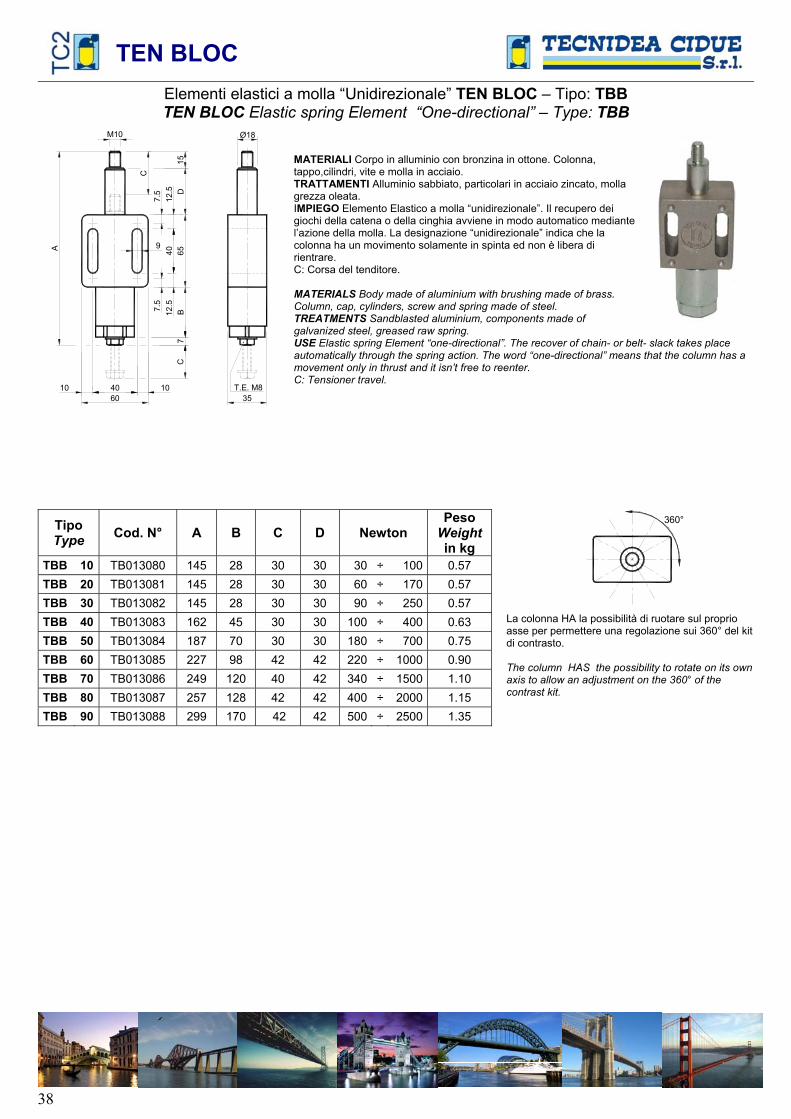
TEN BLOC
38
Elementi elastici a molla “Unidirezionale” TEN BLOC – Tipo: TBBTEN BLOC Elastic spring Element “One-directional” – Type: TBB
60 40 10 10 T.E. M8
35
7
A
7.5
7.5
65D
B12
.5
12.5
40
CM10 Ø18
C
9
15 MATERIALI Corpo in alluminio con bronzina in ottone. Colonna, tappo,cilindri, vite e molla in acciaio. TRATTAMENTI Alluminio sabbiato, particolari in acciaio zincato, molla grezza oleata. IMPIEGO Elemento Elastico a molla “unidirezionale”. Il recupero dei giochi della catena o della cinghia avviene in modo automatico mediante l’azione della molla. La designazione “unidirezionale” indica che la colonna ha un movimento solamente in spinta ed non è libera di rientrare. C: Corsa del tenditore.
MATERIALS Body made of aluminium with brushing made of brass. Column, cap, cylinders, screw and spring made of steel. TREATMENTS Sandblasted aluminium, components made of galvanized steel, greased raw spring. USE Elastic spring Element “one-directional”. The recover of chain- or belt- slack takes place automatically through the spring action. The word “one-directional” means that the column has a movement only in thrust and it isn’t free to reenter. C: Tensioner travel.
TipoType Cod. N° A B C D Newton
PesoWeight in kg
TBB 10 TB013080 145 28 30 30 30 ÷ 100 0.57 TBB 20 TB013081 145 28 30 30 60 ÷ 170 0.57 TBB 30 TB013082 145 28 30 30 90 ÷ 250 0.57 TBB 40 TB013083 162 45 30 30 100 ÷ 400 0.63 TBB 50 TB013084 187 70 30 30 180 ÷ 700 0.75 TBB 60 TB013085 227 98 42 42 220 ÷ 1000 0.90 TBB 70 TB013086 249 120 40 42 340 ÷ 1500 1.10 TBB 80 TB013087 257 128 42 42 400 ÷ 2000 1.15 TBB 90 TB013088 299 170 42 42 500 ÷ 2500 1.35
360°
La colonna HA la possibilità di ruotare sul proprio asse per permettere una regolazione sui 360° del kit di contrasto.
The column HAS the possibility to rotate on its own axis to allow an adjustment on the 360° of the contrast kit.

TEN BLOC
39
Elementi elastici a molla ”antirotazione” TEN BLOC – Tipo: TBATEN BLOC Elastic spring elements ”anti-rotation” – Type: TBA
TBA 10/20/30
Ø18
Ø50
12.5 25
A
7.5
7.5
65
B12
.5
12.5
40
T.C. M6
M10
7.5
C
M8
12
60 40 10 10 35
9
15
D5
MATERIALI Corpo in alluminio con bronzina in ottone. Collare in ottone. Colonna, tappo,cilindri, piastrina, piolo, vite e molla in acciaio. TRATTAMENTI Alluminio sabbiato, particolari in acciaio zincato, molla grezza oleata. IMPIEGO Elemento Elastico a molla “antirotazione”. Il recupero dei giochi della catena o della cinghia avviene in modo automatico mediante l’azione della molla. La designazione “antirotazione” indica che la colonna, una volta messa in posizione, non è più libera di ruotare sui 360°.C: Corsa del tenditore
MATERIALS Body made of aluminium with brushing made of brass. Collar made of brass. Column, cap, cylinders, plate, stake, screw and spring made of steel. TREATMENTS Sandblasted aluminium, components made of galvanized steel, greased raw spring. USE Elastic spring Element “anti-rotation”. The recover of chain- or belt- slack takes place automatically through the spring action. The word “anti-rotation” means that the column, when it is positioned, it isn’t no more free to rotate to 360°.C: Ttensioner travel
TBA 40 Ø18
Ø50
12.5 25
A
7.5
7.5
65B
12.5
12.5
40
T.C. M6
7.5
C
M8
12
60 4010 10 35
9
15D
5
TBAP 50/60/70/80/90 Ø18
Ø50
12.5 25
A
7.5
7.5
6512
.5
12.5
40
T.C. M6
M10
7.5
C 12
604010 10 35
B9
15D
5
TipoType Cod. N° A B C D Newton
PesoWeight in kg
TBA 10 TB013100 130.5 3.5 30 30 30 ÷ 100 0.58 TBA 20 TB013101 130.5 3.5 29 30 60 ÷ 170 0.58 TBA 30 TB013102 130.5 3.5 28 30 90 ÷ 250 0.58 TBA 40 TB013103 152.0 25.0 30 30 100 ÷ 400 0.65 TBAP 50 TB013104 165.5 38.5 27 30 180 ÷ 700 0.80 TBAP 60 TB013105 200.5 73.5 30 30 220 ÷ 1000 0.98 TBAP 70 TB013106 215.5 88.5 30 30 340 ÷ 1500 1.10 TBAP 80 TB013107 250.5 93.5 30 30 400 ÷ 2000 1.20 TBAP 90 TB013108 270.5 143.5 30 30 500 ÷ 2500 1.40
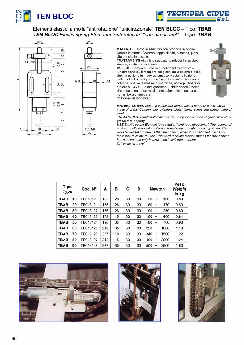
TEN BLOC
40
Elementi elastici a molla “antirotazione” “unidirezionale” TEN BLOC – Tipo: TBABTEN BLOC Elastic spring Elements “anti-rotation” “one-directional” – Type: TBAB
Ø50
12.5 25A
7.5
7.5
65
B12
.5
12.5
40
35
T.C. M6
M10
7.5
C
T.E. M8
7
60 40 10 10
C
Ø18
9
15
12D
5
MATERIALI Corpo in alluminio con bronzina in ottone. Collare in ottone. Colonna, tappo,cilindri, piastrina, piolo, vite e molla in acciaio. TRATTAMENTI Alluminio sabbiato, particolari in acciaio zincato, molla grezza oleata. IMPIEGO Elemento Elastico a molla “antirotazione” e “unidirezionale”. Il recupero dei giochi della catena o della cinghia avviene in modo automatico mediante l’azione della molla. La designazione “antirotazione” indica che la colonna, una volta messa in posizione, non è più libera di ruotare sui 360°. La designazione “unidirezionale” indica che la colonna ha un movimento solamente in spinta ed non è libera di rientrare. C: Corsa del tenditore.
MATERIALS Body made of aluminium with brushing made of brass. Collar made of brass. Column, cap, cylinders, plate, stake, screw and spring made of steel.TREATMENTS Sandblasted aluminium, components made of galvanized steel, greased raw spring. USE Elastic spring Element “anti-rotation” and “one-directional”. The recover of chain- or belt- slack takes place automatically through the spring action. The word “anti-rotation” means that the column, when it is positioned, it isn’t no more free to rotate to 360°. The word “one-directional” means that the column has a movement only in thrust and it isn’t free to renter. C: Tensioner travel.
TipoType Cod. N° A B C D Newton
PesoWeight in kg
TBAB 10 TB013120 155 28 30 30 30 ÷ 100 0.80 TBAB 20 TB013121 155 28 30 30 60 ÷ 170 0.80 TBAB 30 TB013122 155 28 30 30 90 ÷ 250 0.80 TBAB 40 TB013123 172 45 30 30 100 ÷ 400 0.84 TBAB 50 TB013124 190 63 30 30 180 ÷ 700 0.93 TBAB 60 TB013125 212 85 30 30 220 ÷ 1000 1.10 TBAB 70 TB013126 237 110 30 30 340 ÷ 1500 1.22 TBAB 80 TB013127 242 115 30 30 400 ÷ 2000 1.24 TBAB 90 TB013128 287 160 30 30 500 ÷ 2500 1.60

TEN
BLO
C
41
Acc
esso
ri a
richi
esta
A
cces
sorie
son
requ
est
40
10
10
7.57.5
65 A
C
35
B12.5 12.540
Ø18
M
10
159
3.5
60
Type
D
EC
A 1
0...4
0 P
r
M8Ty
pe
DE
CA
50.
..90
Pr
Ele
men
ti E
last
ici a
mol
la T
EN B
LOC
– T
ipo:
DEC
AE
lem
enti
Ela
stic
i a m
olla
TEN
BLO
C –
Tip
o: D
ECA
Pr c
on s
iste
ma
di p
reca
rica
TEN
BLO
C E
last
ic s
prin
g E
lem
ents
– T
ype:
DEC
ATE
N B
LOC
Ela
stic
spr
ing
Ele
men
ts –
Type
:DEC
A P
r with
pre
load
ing
syst
em
M
ATE
RIA
LI C
orpo
in a
llum
inio
con
bro
nzin
a in
otto
ne.C
olon
na, t
appo
, cili
ndri,
vite
e m
olle
in a
ccia
io.
TRA
TTA
MEN
TI A
llum
inio
sab
biat
o, p
artic
olar
i in
acci
aio
zinc
ato,
mol
la g
rezz
a ol
eata
. IM
PIEG
O E
lem
ento
Ela
stic
o a
mol
la. P
uò e
sser
e im
pieg
ato
com
e te
ndic
aten
a o
tend
icin
ghia
ma
anch
e pe
r am
mor
tizza
re d
ecel
erar
e o
para
colp
i.
Si p
osso
no a
vere
con
sis
tem
a di
pre
caric
a pe
r fac
ilita
re le
ope
razi
oni d
i mon
tagg
io (t
ipo
DE
CA
Pr)
. C
: Cor
sa d
ell’e
lem
ento
.
MA
TER
IALS
Bod
y m
ade
of a
lum
iniu
m w
ith b
rush
ing
mad
e of
bra
ss. C
olum
n, c
ap, c
ylin
ders
, scr
ew
and
sprin
gs m
ade
of s
teel
. TR
EATM
ENTS
San
dbla
sted
alu
min
ium
, com
pone
nts
mad
e of
gal
vani
zed
stee
l, gr
ease
d ra
w s
prin
g.
USE
Ela
stic
spr
ing
Ele
men
t. It
can
be u
sed
as c
hain
tens
ione
r or b
elt t
ensi
oner
but
als
o as
sho
ck a
bsor
ber,
dece
lera
tor a
nd b
uffe
r.Y
ou c
an h
ave
them
with
pre
load
ing
syst
em in
ord
er to
faci
litat
e th
e as
sem
blin
g op
erat
ions
(typ
e D
EC
A P
r).
C: E
lem
ent t
rave
l.
DEC
A
M27
M
35
M42
M
80
M13
0 M
200
Tipo
Type
Cod
. N°
A
B
C
Cod
. N°
A
B
C
Cod
. N°
A
B
C
Cod
. N°
A
B
C
Cod
. N°
A
B
C
Cod
. N°
A
B
C
New
ton
DEC
A
10
TB
0200
0127
0
27
TB02
0002
35
25
35
TB02
0003
42
35
42
TB02
0004
80
93
80
TB
0200
0513
017
013
0TB
0200
0620
027
0 20
0 30
÷ 1
00
DEC
A
20
TB
0200
1127
0
25
TB02
0012
35
25
35
TB02
0013
42
35
42
TB02
0014
80
93
80
TB
0200
1513
017
013
0TB
0200
1620
027
0 20
0 60
÷ 1
70
DEC
A
30
TB
0200
2127
0
24
TB02
0022
35
25
33
TB02
0023
42
35
42
TB02
0024
80
93
80
TB
0200
2513
017
013
0TB
0200
2620
027
5 20
0 90
÷ 2
50
DEC
A
40
TB
0200
3127
25
27
TB
0200
3235
35
35
TB
0200
3342
75
42
TB
0200
34
80
110
77
TB02
0035
130
235
130
TB02
0036
200
375
200
100÷
400
D
ECA
50
TB02
0041
27
50
27
TB02
0042
35
50
35
TB02
0043
42
60
42
TB02
0044
80
15
080
TB
0200
4513
025
013
0TB
0200
4620
042
5 20
0 18
0÷ 7
00
DEC
A
60
TB
0200
5130
68
30
TB
0200
5235
75
35
TB
0200
5342
85
42
TB
0200
54
80
195
80
TB02
0055
130
318
130
TB02
0056
200
585
200
220÷
1000
D
ECA
70
TB02
0061
30
88
30
TB02
0062
35
100
35
TB02
0063
42
100
42
TB02
0064
80
23
580
TB
0200
6513
038
513
0TB
0200
6620
070
0 19
7 34
0÷15
00
DEC
A
80
TB
0200
7130
10
0 30
TB
0200
7235
10
035
TB
0200
7342
11
042
TB
0200
74
80
250
80
TB02
0075
130
410
130
TB02
0076
200
700
197
400÷
2000
D
ECA
90
TB02
0081
30
135
30
TB02
0082
35
140
35
TB02
0083
42
150
42
TB02
0084
80
33
580
TB
0200
8513
053
513
0TB
0200
8620
075
0 19
8 50
0÷25
00
DEC
A P
rM
27
M35
M
42
M80
M
130
M20
0 Ti
poTy
peC
od. N
° A
B
C
C
od. N
° A
B
C
C
od. N
° A
B
C
C
od. N
° A
B
C
C
od. N
° A
B
C
C
od. N
° A
B
C
N
ewto
n
DEC
A
10
Pr
TB02
0091
270
27
TB02
0092
3525
35
TB02
0093
4235
42
TB02
0094
80
93
80
TB02
0095
130
170
130
TB02
0096
20
027
0 20
0 30
÷ 1
00
DEC
A
20
Pr
TB02
0101
270
25
TB02
0102
3525
35
TB02
0103
4235
42
TB02
0104
80
93
80
TB02
0105
130
170
130
TB02
0106
20
027
0 20
0 60
÷ 1
70
DEC
A
30
Pr
TB02
0111
270
24
TB02
0112
3525
33
TB02
0113
4235
42
TB02
0114
80
93
80
TB02
0115
130
170
130
TB02
0116
20
027
5 20
0 90
÷ 2
50
DEC
A
40
Pr
TB02
0121
2725
27
TB
0201
2235
35
35TB
0201
2342
75
42TB
0201
24
80
110
77TB
0201
2513
023
513
0TB
0201
26
200
375
200
100÷
400
D
ECA
50
Pr
TB
0201
3127
50
27
TB02
0132
3550
35
TB02
0133
4260
42
TB02
0134
80
15
080
TB02
0135
130
250
130
TB02
0136
20
042
5 20
0 18
0÷ 7
00
DEC
A
60
Pr
TB02
0141
3068
30
TB
0201
4235
75
35TB
0201
4342
85
42TB
0201
44
80
195
80TB
0201
4513
031
813
0TB
0201
46
200
585
200
220÷
1000
D
ECA
70
Pr
TB
0201
5130
88
30
TB02
0152
3510
035
TB02
0153
4210
042
TB02
0154
80
23
580
TB02
0155
130
385
130
TB02
0156
20
070
0 19
7 34
0÷15
00
DEC
A
80
Pr
TB02
0161
3010
0 30
TB
0201
6235
100
35TB
0201
6342
110
42TB
0201
64
80
250
80TB
0201
6513
041
013
0TB
0201
66
200
700
197
400÷
2000
D
ECA
90
Pr
TB
0201
7130
135
30
TB02
0172
3514
035
TB02
0173
4215
042
TB02
0174
80
33
580
TB02
0175
130
535
130
TB02
0176
20
075
0 19
8 50
0÷25
00

TEN
BLO
C
42
Acc
esso
ri a
richi
esta
A
cces
sorie
s on
requ
est
604010
10T.
E. M
835
7
7.5 7.5
65 A B12.5 12.5 40
C
Ø18
C9
15 10
Ele
men
ti E
last
ici a
mol
la T
EN B
LOC
– T
ipo:
DEC
AU
nTE
N B
LOC
Ela
stic
spr
ing
Ele
men
t – T
ype:
DEC
AU
nM
ATE
RIA
LI C
orpo
in a
llum
inio
con
bro
nzin
a in
otto
ne. C
olon
na, t
appo
, cili
ndri,
vite
e m
olle
in a
ccia
io.
TRA
TTA
MEN
TI A
llum
inio
sab
biat
o, p
artic
olar
i in
acci
aio
zinc
ato,
mol
la g
rezz
a ol
eata
.IM
PIEG
O G
rupp
o di
pre
ssio
ne a
mol
la “U
nidi
rezi
onal
e”. C
orsa
e fo
rza
varia
bili.
La
des
igna
zion
e “u
nidi
rezi
onal
e” in
dica
che
la c
olon
na h
a un
mov
imen
to s
olam
ente
in s
pint
a ed
non
è li
bera
di r
ient
rare
.
Cor
sa e
forz
a va
riabi
li.
C: C
orsa
del
l’ele
men
to.
MA
TER
IALS
Bod
y m
ade
of a
lum
iniu
m w
ith b
rush
ing
mad
e of
bra
ss. C
olum
n, c
ap,
cylin
ders
, scr
ew a
nd s
prin
gs m
ade
of s
teel
. TR
EATM
ENTS
San
dbla
sted
alu
min
ium
, com
pone
nts
mad
e of
gal
vani
zed
stee
l, gr
ease
d ra
w s
prin
g.
USE
Spr
ing
pres
sure
uni
t “on
e-di
rect
iona
l”. V
aria
ble
trave
l and
forc
e. T
he w
ord
“one
-di
rect
iona
l” m
eans
that
the
colu
mn
has
a m
ovem
ent o
nly
in th
rust
and
it is
n’t f
ree
to
re-e
nter
. C
: Ele
men
t tra
vel.
DEC
A U
n M
27
M35
M
42
M80
M
130
M20
0
Tipo
Type
Cod
. N°
A
B
C
Cod
. N°
A
B
C
Cod
. N°
A
B
C
Cod
. N°
A
B
C
Cod
. N°
A
B
C
Cod
. N°
A
B
C
New
ton
DEC
A
10
Un
TB02
0181
27
18
15
TB02
0182
35
50
35
TB02
0183
42
50
42
TB02
0184
80
10
080
TB
0201
8513
018
513
0TB
0201
8620
028
5 19
8 30
÷ 1
00
DEC
A
20
Un
TB02
0191
27
18
15
TB02
0192
35
50
35
TB02
0193
42
50
42
TB02
0194
80
10
080
TB
0201
9513
018
513
0TB
0201
9620
028
5 19
8 60
÷ 1
70
DEC
A
30
Un
TB02
0201
27
18
15
TB02
0202
35
50
35
TB02
0203
42
50
42
TB02
0204
80
10
080
TB
0202
0513
018
513
0TB
0202
0620
028
5 19
8 90
÷ 2
50
DEC
A
40
Un
TB02
0211
27
35
27
TB02
0212
35
50
35
TB02
0213
42
85
42
TB02
0214
80
16
080
TB
0202
1513
023
512
7TB
0202
1620
037
5 19
7 10
0÷ 4
00
DEC
A
50
Un
TB02
0221
27
60
27
TB02
0222
35
70
35
TB02
0223
42
68
42
TB02
0224
80
16
080
TB
0202
2513
026
013
0TB
0202
2620
038
5 20
0 18
0÷ 7
00
DEC
A
60
Un
TB02
0231
27
75
27
TB02
0232
35
88
35
TB02
0233
42
88
42
TB02
0234
80
20
080
TB
0202
3513
032
512
8TB
0202
3620
058
5 19
2 22
0÷10
00
DEC
A
70
Un
TB02
0241
27
100
27
TB02
0242
35
110
35
TB02
0243
42
110
40
TB02
0244
80
25
080
TB
0202
4513
039
312
7TB
0202
4620
071
0 19
2 34
0÷15
00
DEC
A
80
Un
TB02
0251
27
105
27
TB02
0252
35
120
35
TB02
0253
42
118
42
TB02
0254
80
26
080
TB
0202
5513
041
812
7TB
0202
5620
071
0 19
2 40
0÷20
00
DEC
A
90
Un
TB02
0261
27
150
27
TB02
0262
35
160
35
TB02
0263
42
160
42
TB02
0264
80
35
080
TB
0202
6513
054
513
0TB
0202
6620
080
0 20
0 50
0÷25
00

TEN BLOC
43
Elementi fissi TEN BLOC – Tipo: TF / Fixed Elements TEN BLOC – Type: TF
6040 10 10
7.5
7.5
12.5
12
.5
40
65
15
84
35
4
M10
9
Cod. TB012990 Peso/Weight: 0.24
MATERIALI Corpo in alluminio. Tappo in plastica. Vite in acciaio. TRATTAMENTI Alluminio sabbiato. Vite allo stato grezzo. IMPIEGO Elemento fisso Tipo TF. Tenditore manuale senza molla interna. Il recupero dei giochi della catena o della cinghia deve essere fatto manualmente mediante la corsa delle due asole di fissaggio.
MATERIALS Body made of aluminium. Cap made of plastic.Screw made of steel.TREATMENTS Sandblasted aluminium. Screw at raw state.USE Fixed Element Type TF. Manual tensioner device without internal spring. The recovery of the slack of the chain or of the belt must be done manually by running the two fixing holes.
Elementi elastici a molla TEN BLOC – Tipo: 2TBElastic spring Elements TEN BLOC – Type: 2TB
10 40 104012020
6015 15
35
Ø18
25
T.E. M8
M12
7
7.5
7.5
65
42
A12
.5
12.5
40
45
10
15
332
S
9
MATERIALI Corpi in alluminio con bronzina in ottone. Scala, unione, colonne, tappi, cilindri, viti e molle in acciaio. TRATTAMENTI Alluminio sabbiato, particolari in acciaio zincato, molla grezza oleata. IMPIEGO Elemento Elastico a molla “doppio”. Il recupero dei giochi della catena o della cinghia avviene in modo automatico mediante l’azione delle molle, la forza di questo elemento è doppia rispetto a quella di un elemento singolo. Le viti che fuoriescono dai tappi del tenditore sono usate per le operazioni di precarica. C: Corsa del tenditore 32 mm.
MATERIALS Body made of aluminium with brushing made of brass. Stair, union, columns, caps, cylinders, plate, screws and springs made of steel. TREATMENTS Sandblasted aluminium, components made of galvanized steel, greased raw spring. USE “Double” spring elastic element. The recover of chain- or belt- slack takes place automatically through the spring action. The force of this element is twice that of a single element. The screws that come out from the caps of the tensioner are used for the operations of preloading. C:Tensioner travel: 32 mm.
TipoType Cod. N° A S Newton
PesoWeight in kg
2TB 40 TB013143 31.5 3.5 200 ÷ 800 1.40 2TB 50 TB013144 73.0 10.0 360 ÷ 1400 1.86 2TB 60 TB013145 81.5 3.5 440 ÷ 2000 1.93 2TB 70 TB013146 163.0 10.0 680 ÷ 3000 2.75
Montati con il kit 2V di pag 55: / Assembled with the 2V kit of page 55:
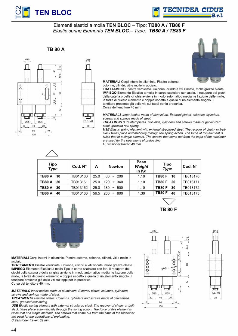
TEN BLOC
44
Elementi elastici a molla TEN BLOC – Tipo: TB80 A / TB80 FElastic spring Elements TEN BLOC – Type: TB80 A / TB80 F
TB 80 A
38
68
80
20 40 20
40.5
M10 Ø18A
7
10010 10
Ø35 Ø35
15.5
15.5
379
15
40
T.E. M8
MATERIALI Corpi interni in alluminio. Piastre esterne, colonne, cilindri, viti e molle in acciaio. TRATTAMENTI Piastre verniciate. Colonne, cilindri e viti zincate, molle grezze oleate. IMPIEGO Elemento Elastico a molla in corpo scatolare con asole. Il recupero dei giochi della catena o della cinghia avviene in modo automatico mediante l’azione delle molle, la forza di questo elemento è doppia rispetto a quella di un elemento singolo. Il tenditore presenta già delle viti sui tappi per la precarica. Corsa del tenditore 40 mm.
MATERIALS Inner bodies made of aluminium. External plates, columns, cylinders, screws and springs made of steel.TREATMENTS Painted plates. Columns, cylinders and screws made of galvanized steel, greased raw spring.USE Elastic spring element with external structured steel. The recover of chain- or belt- slack takes place automatically through the spring action. The force of this element is twice that of a single element. The screws that come out from the caps of the tensioner are used for the operations of preloading. C:Tensioner traver: 40 mm.
TipoType Cod. N° A Newton
PesoWeight in Kg
TipoType Cod. N°
TB80 A 10 TB013160 25.0 60 ÷ 200 1.10 TB80 F 10 TB013170TB80 A 20 TB013161 25.0 120 ÷ 340 1.10 TB80 F 20 TB013171TB80 A 30 TB013162 25.0 180 ÷ 500 1.10 TB80 F 30 TB013172TB80 A 40 TB013163 56.5 200 ÷ 800 1.30 TB80 F 40 TB013173
MATERIALI Corpi interni in alluminio. Piastre esterne, colonne, cilindri, viti e molle in acciaio.TRATTAMENTI Piastre verniciate. Colonne, cilindri e viti zincate, molle grezze oleate. IMPIEGO Elemento Elastico a molla Tipo in corpo scatolare con fori. Il recupero dei giochi della catena o della cinghia avviene in modo automatico mediante l’azione delle molle, la forza di questo elemento è doppia rispetto a quella di un elemento singolo. Il tenditore presenta già delle viti sui tappi per la precarica. Corsa del tenditore 40 mm.
MATERIALS Inner bodies made of aluminium. External plates, columns, cylinders, screws and springs made of steel.TREATMENTS Painted plates. Columns, cylinders and screws made of galvanized steel, greased raw spring.USE Elastic spring element with external structured steel. The recover of chain- or belt- slack takes place automatically through the spring action. The force of this element is twice that of a single element. The screws that come out from the caps of the tensioner are used for the operations of preloading. C:Tensioner traver: 32 mm.
TB 80 F
68
80
20 40 20
40.5
A
7
10 10
Ø35 Ø35
193x
10=3
0
Ø6.5
15
38
T.E. M8
100
40
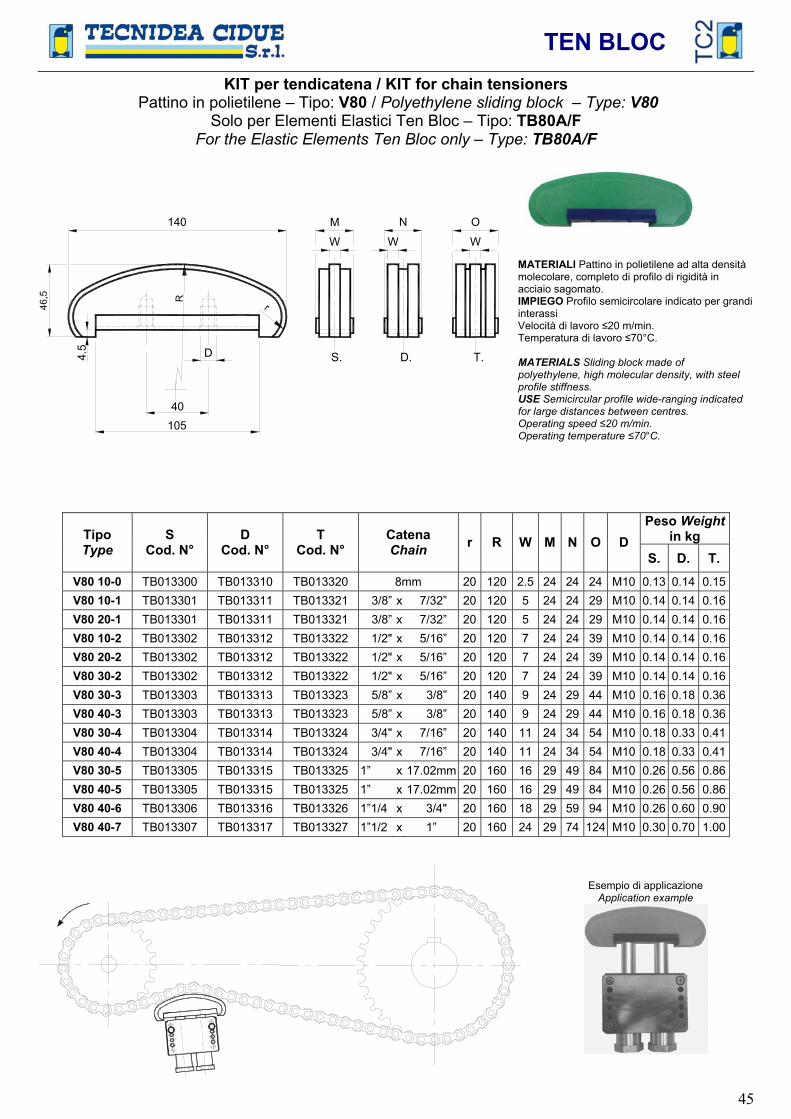
TEN BLOC
45
KIT per tendicatena / KIT for chain tensioners Pattino in polietilene – Tipo: V80 / Polyethylene sliding block – Type: V80
Solo per Elementi Elastici Ten Bloc – Tipo: TB80A/FFor the Elastic Elements Ten Bloc only – Type: TB80A/F
r
140
4.5
R
40
N
S. D. T.
W
M
WW
O
105
D
MATERIALI Pattino in polietilene ad alta densità molecolare, completo di profilo di rigidità in acciaio sagomato. IMPIEGO Profilo semicircolare indicato per grandi interassi Velocità di lavoro 20 m/min.Temperatura di lavoro 70°C.
MATERIALS Sliding block made of polyethylene, high molecular density, with steel profile stiffness. USE Semicircular profile wide-ranging indicated for large distances between centres. Operating speed 20 m/min. Operating temperature 70°C.
Peso Weightin kgTipo
TypeS
Cod. N° D
Cod. N° T
Cod. N° Catena Chain r R W M N O D
S. D. T. V80 10-0 TB013300 TB013310 TB013320 8mm 20 120 2.5 24 24 24 M10 0.13 0.14 0.15V80 10-1 TB013301 TB013311 TB013321 3/8” x 7/32” 20 120 5 24 24 29 M10 0.14 0.14 0.16V80 20-1 TB013301 TB013311 TB013321 3/8” x 7/32” 20 120 5 24 24 29 M10 0.14 0.14 0.16V80 10-2 TB013302 TB013312 TB013322 1/2" x 5/16” 20 120 7 24 24 39 M10 0.14 0.14 0.16V80 20-2 TB013302 TB013312 TB013322 1/2" x 5/16” 20 120 7 24 24 39 M10 0.14 0.14 0.16V80 30-2 TB013302 TB013312 TB013322 1/2" x 5/16” 20 120 7 24 24 39 M10 0.14 0.14 0.16V80 30-3 TB013303 TB013313 TB013323 5/8” x 3/8” 20 140 9 24 29 44 M10 0.16 0.18 0.36V80 40-3 TB013303 TB013313 TB013323 5/8” x 3/8” 20 140 9 24 29 44 M10 0.16 0.18 0.36V80 30-4 TB013304 TB013314 TB013324 3/4" x 7/16” 20 140 11 24 34 54 M10 0.18 0.33 0.41V80 40-4 TB013304 TB013314 TB013324 3/4" x 7/16” 20 140 11 24 34 54 M10 0.18 0.33 0.41V80 30-5 TB013305 TB013315 TB013325 1” x 17.02mm 20 160 16 29 49 84 M10 0.26 0.56 0.86V80 40-5 TB013305 TB013315 TB013325 1” x 17.02mm 20 160 16 29 49 84 M10 0.26 0.56 0.86V80 40-6 TB013306 TB013316 TB013326 1”1/4 x 3/4" 20 160 18 29 59 94 M10 0.26 0.60 0.90V80 40-7 TB013307 TB013317 TB013327 1”1/2 x 1” 20 160 24 29 74 124 M10 0.30 0.70 1.00
Esempio di applicazione Application example
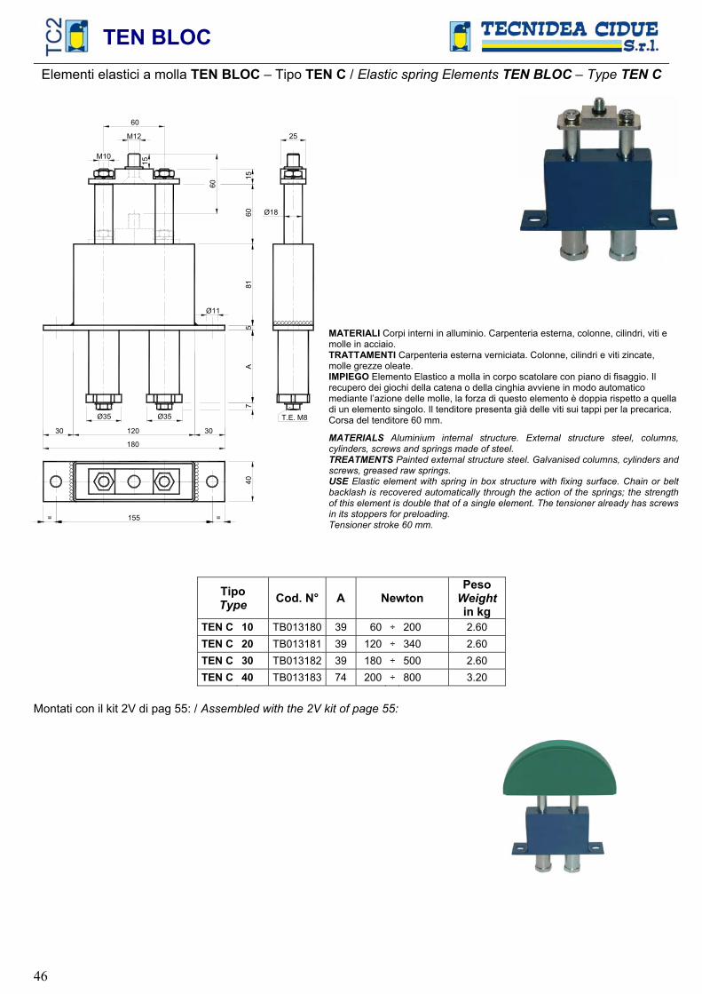
TEN BLOC
46
Elementi elastici a molla TEN BLOC – Tipo TEN C / Elastic spring Elements TEN BLOC – Type TEN CC
CC
CC
CC
CC
CC
405
8160
15
60
M12
A
180
M1015
120
Ø18
25
Ø11
30 30
7
Ø35 Ø35
155= =
T.E. M8
60
CCCCCCCCCCC
MATERIALI Corpi interni in alluminio. Carpenteria esterna, colonne, cilindri, viti e molle in acciaio. TRATTAMENTI Carpenteria esterna verniciata. Colonne, cilindri e viti zincate, molle grezze oleate. IMPIEGO Elemento Elastico a molla in corpo scatolare con piano di fisaggio. Il recupero dei giochi della catena o della cinghia avviene in modo automatico mediante l’azione delle molle, la forza di questo elemento è doppia rispetto a quella di un elemento singolo. Il tenditore presenta già delle viti sui tappi per la precarica. Corsa del tenditore 60 mm.
MATERIALS Aluminium internal structure. External structure steel, columns, cylinders, screws and springs made of steel. TREATMENTS Painted external structure steel. Galvanised columns, cylinders and screws, greased raw springs. USE Elastic element with spring in box structure with fixing surface. Chain or belt backlash is recovered automatically through the action of the springs; the strength of this element is double that of a single element. The tensioner already has screws in its stoppers for preloading. Tensioner stroke 60 mm.
TipoType Cod. N° A Newton
PesoWeight in kg
TEN C 10 TB013180 39 60 ÷ 200 2.60 TEN C 20 TB013181 39 120 ÷ 340 2.60 TEN C 30 TB013182 39 180 ÷ 500 2.60 TEN C 40 TB013183 74 200 ÷ 800 3.20
Montati con il kit 2V di pag 55: / Assembled with the 2V kit of page 55:

TEN BLOC
47
Elementi elastici a molla TEN BLOC - Tipo TEN B / Elastic spring Elements TEN BLOC - Type TEN B
CCCCCCCCCCCCCCCCCCCCCCCCCCCCCCCCC
CC
CC
CC
CC
CC
C
Ø18
25
681
8015
60
M12
A
180
M10
15
120
Ø13
30 30
7
Ø35 Ø35
50
155= =
T.E. M8
78
S
CCCCCCCCCCCCCCCCCCCCCCCCCCCCCCCCCCCCCCCCCCCCCMATERIALI Corpi interni in alluminio. Carpenteria esterna, colonne, cilindri, viti e molle in acciaio. TRATTAMENTI Carpenteria esterna verniciata. Colonne, cilindri e viti zincate, molle grezze oleate. IMPIEGO Elemento Elastico a molla in corpo scatolare con piano di fissaggio. Il recupero dei giochi della catena o della cinghia avviene in modo automatico mediante l’azione delle molle, la forza di questo elemento è doppia rispetto a quella di un elemento singolo. Il tenditore presenta già delle viti sui tappi per la precarica.Corsa del tenditore 78 mm.
MATERIALS Aluminium internal structures. External structure steel, columns, cylinders, screws and springs made of steel. TREATMENTS Painted external structure steel. Galvanised columns, cylinders and screws, greased raw springs. USE Elastic element with spring in box structure with fixing surface. Chain or belt backlash is recovered automatically through the action of the springs; the strength of this element is double that of a single element. The tensioner already has screws in its stoppers for preloading. Tensioner stroke 78 mm.
TipoType Cod. N° A S Newton
PesoWeight in kg
TEN B 10 TB013190 91 10 60 ÷ 200 2.10 TEN B 20 TB013191 91 10 120 ÷ 340 2.10 TEN B 30 TB013192 91 10 180 ÷ 500 2.10 TEN B 40 TB013193 94.5 3.5 200 ÷ 800 2.30 TEN B 50 TB013194 134.5 3.5 360 ÷ 1400 3.20 TEN B 60 TB013195 194.5 3.5 440 ÷ 2000 3.60 TEN B 70 TB013196 244.5 3.5 680 ÷ 3000 4.10 TEN B 80 TB013197 244.5 3.5 800 ÷ 4000 4.10 TEN B 90 TB013198 319.5 3.5 1000 ÷ 5000 4.60
Montati con il kit 2V di pag 55: / Assembled with the 2V kit of page 55:
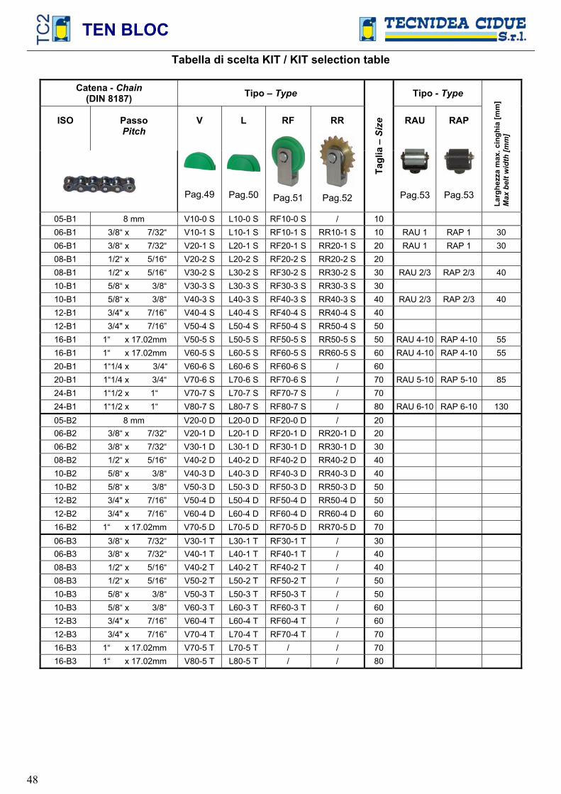
TEN BLOC
48
Tabella di scelta KIT / KIT selection table
Catena - Chain(DIN 8187) Tipo – Type Tipo - Type
ISO PassoPitch
V
Pag.49
L
Pag.50
RF
Pag.51
RR
Pag.52
Tagl
ia –
Siz
e RAU
Pag.53
RAP
Pag.53
Larg
hezz
a m
ax. c
ingh
ia [m
m]
Max
bel
t wid
th [m
m]
05-B1 8 mm V10-0 S L10-0 S RF10-0 S / 10 06-B1 3/8“ x 7/32“ V10-1 S L10-1 S RF10-1 S RR10-1 S 10 RAU 1 RAP 1 30 06-B1 3/8“ x 7/32“ V20-1 S L20-1 S RF20-1 S RR20-1 S 20 RAU 1 RAP 1 30 08-B1 1/2“ x 5/16“ V20-2 S L20-2 S RF20-2 S RR20-2 S 20 08-B1 1/2“ x 5/16“ V30-2 S L30-2 S RF30-2 S RR30-2 S 30 RAU 2/3 RAP 2/3 40 10-B1 5/8“ x 3/8“ V30-3 S L30-3 S RF30-3 S RR30-3 S 30 10-B1 5/8“ x 3/8“ V40-3 S L40-3 S RF40-3 S RR40-3 S 40 RAU 2/3 RAP 2/3 40 12-B1 3/4" x 7/16” V40-4 S L40-4 S RF40-4 S RR40-4 S 40 12-B1 3/4" x 7/16” V50-4 S L50-4 S RF50-4 S RR50-4 S 50 16-B1 1“ x 17.02mm V50-5 S L50-5 S RF50-5 S RR50-5 S 50 RAU 4-10 RAP 4-10 55 16-B1 1“ x 17.02mm V60-5 S L60-5 S RF60-5 S RR60-5 S 60 RAU 4-10 RAP 4-10 55 20-B1 1“1/4 x 3/4“ V60-6 S L60-6 S RF60-6 S / 60 20-B1 1“1/4 x 3/4“ V70-6 S L70-6 S RF70-6 S / 70 RAU 5-10 RAP 5-10 85 24-B1 1“1/2 x 1“ V70-7 S L70-7 S RF70-7 S / 70 24-B1 1“1/2 x 1“ V80-7 S L80-7 S RF80-7 S / 80 RAU 6-10 RAP 6-10 130 05-B2 8 mm V20-0 D L20-0 D RF20-0 D / 20 06-B2 3/8“ x 7/32“ V20-1 D L20-1 D RF20-1 D RR20-1 D 20 06-B2 3/8“ x 7/32“ V30-1 D L30-1 D RF30-1 D RR30-1 D 30 08-B2 1/2“ x 5/16“ V40-2 D L40-2 D RF40-2 D RR40-2 D 40 10-B2 5/8“ x 3/8“ V40-3 D L40-3 D RF40-3 D RR40-3 D 40 10-B2 5/8“ x 3/8“ V50-3 D L50-3 D RF50-3 D RR50-3 D 50 12-B2 3/4" x 7/16” V50-4 D L50-4 D RF50-4 D RR50-4 D 50 12-B2 3/4" x 7/16” V60-4 D L60-4 D RF60-4 D RR60-4 D 60 16-B2 1“ x 17.02mm V70-5 D L70-5 D RF70-5 D RR70-5 D 70 06-B3 3/8“ x 7/32“ V30-1 T L30-1 T RF30-1 T / 30 06-B3 3/8“ x 7/32“ V40-1 T L40-1 T RF40-1 T / 40 08-B3 1/2“ x 5/16“ V40-2 T L40-2 T RF40-2 T / 40 08-B3 1/2“ x 5/16“ V50-2 T L50-2 T RF50-2 T / 50 10-B3 5/8“ x 3/8“ V50-3 T L50-3 T RF50-3 T / 50 10-B3 5/8“ x 3/8“ V60-3 T L60-3 T RF60-3 T / 60 12-B3 3/4" x 7/16” V60-4 T L60-4 T RF60-4 T / 60 12-B3 3/4" x 7/16” V70-4 T L70-4 T RF70-4 T / 70 16-B3 1“ x 17.02mm V70-5 T L70-5 T / / 70 16-B3 1“ x 17.02mm V80-5 T L80-5 T / / 80
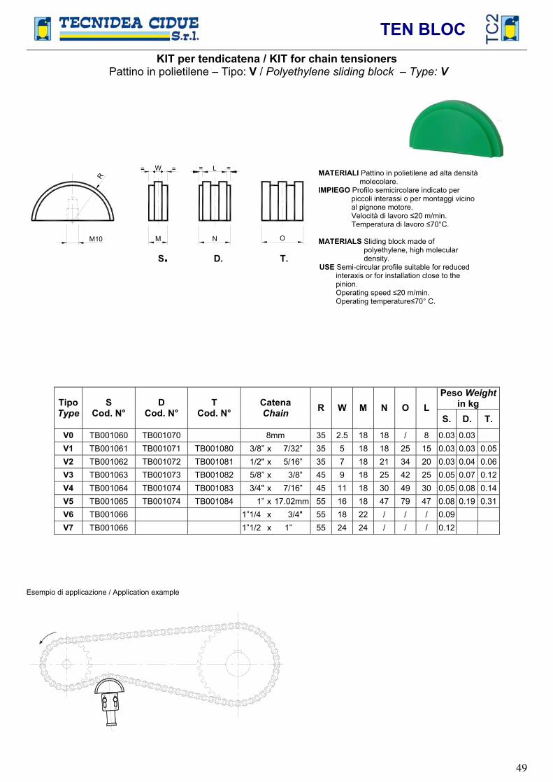
TEN BLOC
49
KIT per tendicatena / KIT for chain tensioners Pattino in polietilene – Tipo: V / Polyethylene sliding block – Type: V
R
M10
L=W
M N O
=
S. D. T.
MATERIALI Pattino in polietilene ad alta densità molecolare.
IMPIEGO Profilo semicircolare indicato per piccoli interassi o per montaggi vicino
al pignone motore. Velocità di lavoro 20 m/min. Temperatura di lavoro 70°C.
MATERIALS Sliding block made ofpolyethylene, high molecular
density. USE Semi-circular profile suitable for reduced interaxis or for installation close to the pinion. Operating speed 20 m/min. Operating temperature 70° C.
Peso Weightin kgTipo
TypeS
Cod. N° D
Cod. N° T
Cod. N° Catena Chain R W M N O L
S. D. T. V0 TB001060 TB001070 8mm 35 2.5 18 18 / 8 0.03 0.03 V1 TB001061 TB001071 TB001080 3/8” x 7/32” 35 5 18 18 25 15 0.03 0.03 0.05V2 TB001062 TB001072 TB001081 1/2" x 5/16” 35 7 18 21 34 20 0.03 0.04 0.06V3 TB001063 TB001073 TB001082 5/8” x 3/8” 45 9 18 25 42 25 0.05 0.07 0.12V4 TB001064 TB001074 TB001083 3/4" x 7/16” 45 11 18 30 49 30 0.05 0.08 0.14V5 TB001065 TB001074 TB001084 1” x 17.02mm 55 16 18 47 79 47 0.08 0.19 0.31V6 TB001066 1”1/4 x 3/4" 55 18 22 / / / 0.09 V7 TB001066 1”1/2 x 1” 55 24 24 / / / 0.12
Esempio di applicazione / Application example

TEN BLOC
50
KIT per tendicatena / KIT for chain tensioners Pattino in polietilene – Tipo: L / Polyethylene sliding block – Type: L
RL=W
M N O
=
M10
G
S. D. T.
La forma del profilo è stata realizzata in modo che ci siano sempre due/tre rulli di catena in contatto sul piano di lavoro (Fig.1). Questa soluzione sostituisce in modo soddisfacente ed economico le applicazioni dei grossi pattini con i grandi raggi dei profili di scorrimento.
The profile shape has been created so that there are always two/three chain rollers in contact with the work surface (fig.1). This solution is an effective and inexpensive alternative to using large sliders with extensive sliding profile ranges.
MATERIALI Pattino in polietilene ad alta densità molecolare.
IMPIEGO Profilo semicircolare ribassato indicato per grandi interassi.
Velocità di lavoro 20 m/min. Temperatura di lavoro 70°C.
MATERIALS Sliding block made of polyethylene, high
molecular density. USE Semi-circular lowered profile,
suitable for large interaxis. Operating speed 20 m/min. Operating temperature 70°C.
Peso Weightin kgTipo
Type S
Cod. N° D
Cod. N° T
Cod. N° Catena Chain G R W M N O L
S. D. T. L0 TB001097 TB001107 8mm 30 35 2.5 18 18 / 8 0.03 0.03 L1 TB001098 TB001108 TB001117 3/8” x 7/32” 30 35 5 18 18 25 15 0.03 0.03 0.05L2 TB001099 TB001109 TB001118 1/2" x 5/16” 30 35 7 18 21 34 20 0.03 0.04 0.06L3 TB001100 TB001110 TB001119 5/8” x 3/8” 37 45 9 18 25 42 25 0.04 0.06 0.11L4 TB001101 TB001111 TB001120 3/4" x 7/16” 37 45 11 18 30 49 30 0.04 0.07 0.13L5 TB001102 TB001112 TB001121 1” x 17.02mm 46 55 16 20 47 79 47 0.08 0.17 0.30L6 TB001103 1”1/4 x 3/4" 46 55 18 22 / / / 0.08 L7 TB001104 1”1/2 x 1” 46 55 24 24 / / / 0.11
Esempio di applicazione / Application example
Fig.1
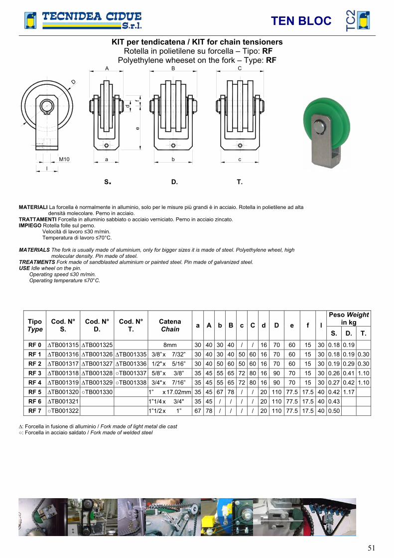
TEN BLOC
51
KIT per tendicatena / KIT for chain tensioners Rotella in polietilene su forcella – Tipo: RF
Polyethylene wheeset on the fork – Type: RF
a
d
ef
l
D
b c
A B C
M10
S. D. T.
MATERIALI La forcella è normalmente in alluminio, solo per le misure più grandi è in acciaio. Rotella in polietilene ad alta densità molecolare. Perno in acciaio.
TRATTAMENTI Forcella in alluminio sabbiato o acciaio verniciato. Perno in acciaio zincato. IMPIEGO Rotella folle sul perno. Velocità di lavoro 30 m/min. Temperatura di lavoro 70°C.
MATERIALS The fork is usually made of aluminium, only for bigger sizes it is made of steel. Polyethylene wheel, high molecular density. Pin made of steel.
TREATMENTS Fork made of sandblasted aluminium or painted steel. Pin made of galvanized steel. USE Idle wheel on the pin. Operating speed 30 m/min. Operating temperature 70°C.
Peso Weightin kgTipo
TypeCod. N°
S.Cod. N°
D.Cod. N°
T.Catena Chain a A b B c C d D e f l
S. D. T. RF 0 TB001315 TB001325 8mm 30 40 30 40 / / 16 70 60 15 30 0.18 0.19 RF 1 TB001316 TB001326 TB001335 3/8” x 7/32” 30 40 30 40 50 60 16 70 60 15 30 0.18 0.19 0.30RF 2 TB001317 TB001327 TB001336 1/2" x 5/16” 30 40 50 60 50 60 16 70 60 15 30 0.19 0.29 0.30RF 3 TB001318 TB001328 TB001337 5/8” x 3/8” 35 45 55 65 72 80 16 90 70 15 30 0.26 0.41 1.10RF 4 TB001319 TB001329 TB001338 3/4" x 7/16” 35 45 55 65 72 80 16 90 70 15 30 0.27 0.42 1.10RF 5 TB001320 TB001330 1” x17.02mm 35 45 67 78 / / 20 110 77.5 17.5 40 0.42 1.17 RF 6 TB001321 1”1/4 x 3/4" 35 45 / / / / 20 110 77.5 17.5 40 0.43 RF 7 TB001322 1”1/2 x 1” 67 78 / / / / 20 110 77.5 17.5 40 0.50
: Forcella in fusione di alluminio / Fork made of light metal die cast: Forcella in acciaio saldato / Fork made of welded steel
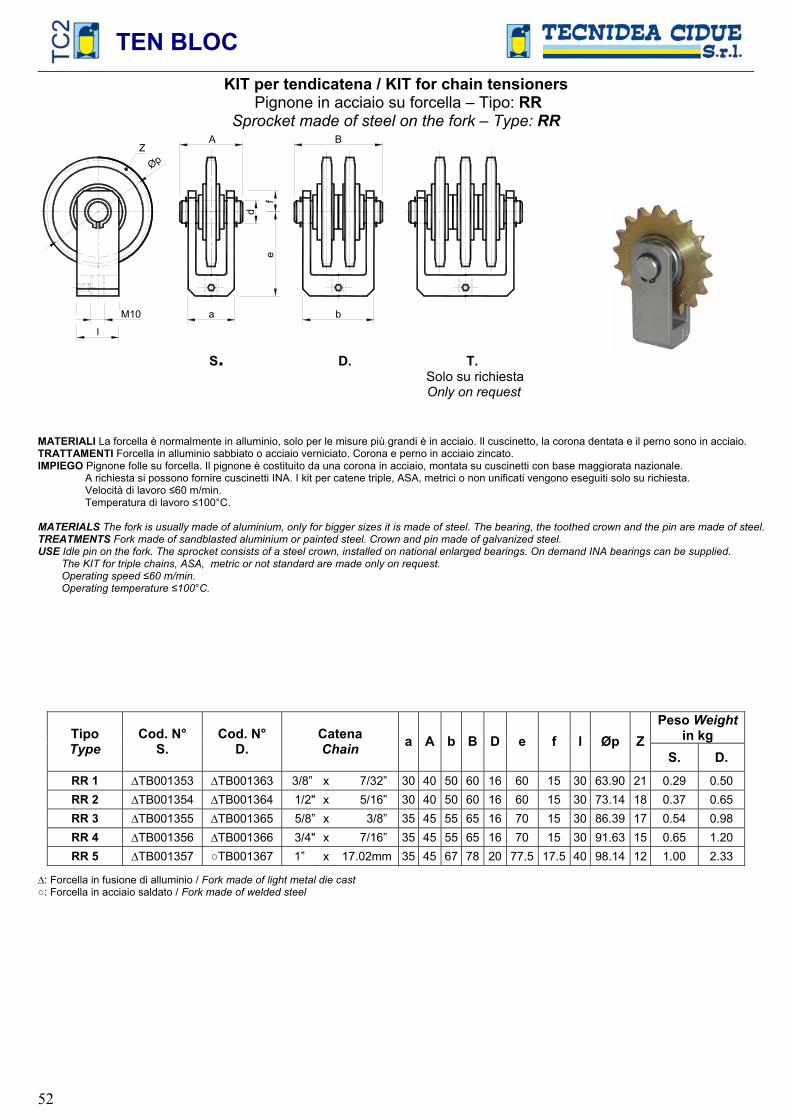
TEN BLOC
52
KIT per tendicatena / KIT for chain tensioners Pignone in acciaio su forcella – Tipo: RR
Sprocket made of steel on the fork – Type: RR
a
d
ef
l
b
A B
M10
Z
Øp
S. D. T. Solo su richiesta
Only on request
MATERIALI La forcella è normalmente in alluminio, solo per le misure più grandi è in acciaio. Il cuscinetto, la corona dentata e il perno sono in acciaio. TRATTAMENTI Forcella in alluminio sabbiato o acciaio verniciato. Corona e perno in acciaio zincato.IMPIEGO Pignone folle su forcella. Il pignone è costituito da una corona in acciaio, montata su cuscinetti con base maggiorata nazionale. A richiesta si possono fornire cuscinetti INA. I kit per catene triple, ASA, metrici o non unificati vengono eseguiti solo su richiesta. Velocità di lavoro 60 m/min. Temperatura di lavoro 100°C.
MATERIALS The fork is usually made of aluminium, only for bigger sizes it is made of steel. The bearing, the toothed crown and the pin are made of steel. TREATMENTS Fork made of sandblasted aluminium or painted steel. Crown and pin made of galvanized steel.USE Idle pin on the fork. The sprocket consists of a steel crown, installed on national enlarged bearings. On demand INA bearings can be supplied. The KIT for triple chains, ASA, metric or not standard are made only on request. Operating speed 60 m/min. Operating temperature 100°C.
Peso Weightin kgTipo
TypeCod. N°
S.Cod. N°
D.Catena Chain a A b B D e f l Øp Z
S. D. RR 1 TB001353 TB001363 3/8” x 7/32” 30 40 50 60 16 60 15 30 63.90 21 0.29 0.50 RR 2 TB001354 TB001364 1/2" x 5/16” 30 40 50 60 16 60 15 30 73.14 18 0.37 0.65 RR 3 TB001355 TB001365 5/8” x 3/8” 35 45 55 65 16 70 15 30 86.39 17 0.54 0.98 RR 4 TB001356 TB001366 3/4" x 7/16” 35 45 55 65 16 70 15 30 91.63 15 0.65 1.20 RR 5 TB001357 TB001367 1” x 17.02mm 35 45 67 78 20 77.5 17.5 40 98.14 12 1.00 2.33
: Forcella in fusione di alluminio / Fork made of light metal die cast: Forcella in acciaio saldato / Fork made of welded steel
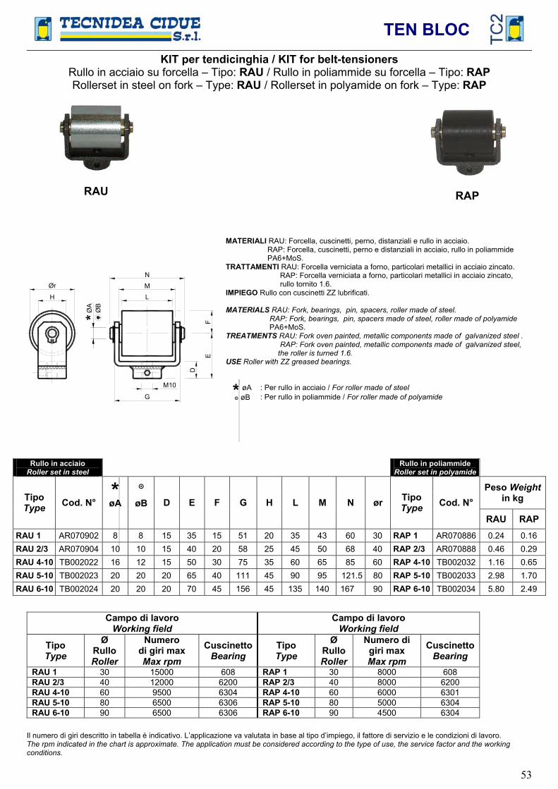
TEN BLOC
53
KIT per tendicinghia / KIT for belt-tensioners Rullo in acciaio su forcella – Tipo: RAU / Rullo in poliammide su forcella – Tipo: RAPRollerset in steel on fork – Type: RAU / Rollerset in polyamide on fork – Type: RAP
Ør
H L
M
N
G
D
EF
M10
ØA
ØB
*
MATERIALI RAU: Forcella, cuscinetti, perno, distanziali e rullo in acciaio. RAP: Forcella, cuscinetti, perno e distanziali in acciaio, rullo in poliammide PA6+MoS. TRATTAMENTI RAU: Forcella verniciata a forno, particolari metallici in acciaio zincato. RAP: Forcella verniciata a forno, particolari metallici in acciaio zincato, rullo tornito 1.6. IMPIEGO Rullo con cuscinetti ZZ lubrificati.
MATERIALS RAU: Fork, bearings, pin, spacers, roller made of steel. RAP: Fork, bearings, pin, spacers made of steel, roller made of polyamide
PA6+MoS.TREATMENTS RAU: Fork oven painted, metallic components made of galvanized steel . RAP: Fork oven painted, metallic components made of galvanized steel, the roller is turned 1.6. USE Roller with ZZ greased bearings.
* øA : Per rullo in acciaio / For roller made of steel øB : Per rullo in poliammide / For roller made of polyamide
Rullo in acciaio Roller set in steel
Rullo in poliammide Roller set in polyamide
* Peso Weightin kg Tipo
Type Cod. N° øA øB D E F G H L M N ør TipoType Cod. N°
RAU RAP RAU 1 AR070902 8 8 15 35 15 51 20 35 43 60 30 RAP 1 AR070886 0.24 0.16 RAU 2/3 AR070904 10 10 15 40 20 58 25 45 50 68 40 RAP 2/3 AR070888 0.46 0.29 RAU 4-10 TB002022 16 12 15 50 30 75 35 60 65 85 60 RAP 4-10 TB002032 1.16 0.65 RAU 5-10 TB002023 20 20 20 65 40 111 45 90 95 121.5 80 RAP 5-10 TB002033 2.98 1.70 RAU 6-10 TB002024 20 20 20 70 45 156 45 135 140 167 90 RAP 6-10 TB002034 5.80 2.49
Campo di lavoro Working field
Campo di lavoro Working field
TipoType
ØRulloRoller
Numero di giri max Max rpm
CuscinettoBearing
TipoType
ØRulloRoller
Numero di giri max Max rpm
CuscinettoBearing
RAU 1 30 15000 608 RAP 1 30 8000 608 RAU 2/3 40 12000 6200 RAP 2/3 40 8000 6200 RAU 4-10 60 9500 6304 RAP 4-10 60 6000 6301 RAU 5-10 80 6500 6306 RAP 5-10 80 5000 6304 RAU 6-10 90 6500 6306 RAP 6-10 90 4500 6304
Il numero di giri descritto in tabella è indicativo. L’applicazione va valutata in base al tipo d’impiego, il fattore di servizio e le condizioni di lavoro. The rpm indicated in the chart is approximate. The application must be considered according to the type of use, the service factor and the working conditions.
RAU RAP

TEN BLOC
54
Tabella di scelta KIT / KIT selection table
Catena - Chain(DIN 8187) Tipo – Type Tipo – Type
ISO PassoPitch
Tagl
ia –
Siz
e
2V
Pag.55
2RR
Pag.56
Pag.434647
2RAU
Pag.57
2RAP
Pag.57
Larg
hezz
a m
ax. c
ingh
ia [m
m]
Max
bel
t wid
th [m
m]
16-B1 1“ x 17.02mm 2V 40-5 S 2RR 40-5 S 40 2RAU 4 2RAP 4 55 16-B1 1“ x 17.02mm 2V 40-5 S 2RR 50-5 S 50 20-B1 1“1/4 x 3/4“ 2V 50-6 S 2RR 50-6 S 50 2RAU 5 2RAP 5 85 20-B1 1“1/4 x 3/4“ 2V 60-6 S 2RR 60-6 S 60 2RAU 5 2RAP 5 85 24-B1 1“1/2 x 1“ 2V 60-7 S 2RR 60-7 S 60 2RAU 6 2RAP 6 130 24-B1 1“1/2 x 1“ 2V 70-7 S 2RR 70-7 S 70 2RAU 6 2RAP 6 130 28-B1 1“3/4 x 1“1/4 2V 60-8 S 2RR 60-8 S 60 28-B1 1“3/4 x 1“1/4 2V 70-8 S 2RR 70-8 S 70 32-B1 2“ x 1“1/4 2V 70-9 S 2RR 70-9 S 70 32-B1 2“ x 1“1/4 2V 80-9 S 2RR 80-9 S 80 16-B2 1“ x 17.02mm 2V 50-5 D 2RR 50-5 D 50 16-B2 1“ x 17.02mm 2V 60-5 D 2RR 60-5 D 60 20-B2 1“1/4 x 3/4“ 2V 60-6 D 2RR 60-6 D 60 20-B2 1“1/4 x 3/4“ 2V 70-6 D 2RR 70-7 D 70 24-B2 1“1/2 x 1“ 2V 70-7 D 2RR 70-7 D 70 24-B2 1“1/2 x 1“ 2V 80-7 D 2RR 80-7 D 80 28-B2 1“3/4 x 1“1/4 2V 80-8 D 2RR 80-8 D 80 28-B2 1“3/4 x 1“1/4 2V 90-8 D 2RR 90-8 D 90 32-B2 2“ x 1“1/4 2V 90-9 D 2RR 70-9 D 90 16-B3 1“ x 17.02mm 2V 60-5 T 60 16-B3 1“ x 17.02mm 2V 70-5 T 70 20-B3 1“1/4 x 3/4“ 2V 70-6 T 70 20-B3 1“1/4 x 3/4“ 2V 80-6 T 80 24-B3 1“1/2 x 1“ 2V 90-7 T 90
2TB TENC TENB
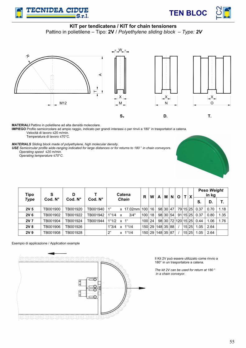
TEN BLOC
55
KIT per tendicatena / KIT for chain tensioners Pattino in polietilene – Tipo: 2V / Polyethylene sliding block – Type: 2V
R
W=
N OA
T
MM12
X X X
S. D. T.
MATERIALI Pattino in polietilene ad alta densità molecolare. IMPIEGO Profilo semicircolare ad ampio raggio, indicato per grandi interassi o per rinvii a 180° in trasportatori a catena. Velocità di lavoro 20 m/min. Temperatura di lavoro 70°C.
MATERIALS Sliding block made of polyethylene, high molecular density. USE Semicircular profile wide-ranging indicated for large distances or for returns to 180 ° in chain conveyors. Operating speed 20 m/min. Operating temperature 70°C.
Peso Weight in kg Tipo
TypeS
Cod. N° D
Cod. N° T
Cod. N° Catena Chain R W A M N O T X
S. D. T. 2V 5 TB001900 TB001920 TB001940 1” x 17.02mm 100 16 98 30 47 79 15 25 0.37 0.70 1.182V 6 TB001902 TB001922 TB001942 1”1/4 x 3/4" 100 18 98 30 54 91 15 25 0.37 0.80 1.352V 7 TB001904 TB001924 TB001944 1“1/2 x 1“ 100 24 98 30 72 120 15 25 0.44 1.06 1.762V 8 TB001906 TB001926 1”3/4 x 1“1/4 150 29 148 35 88 / 15 25 1.05 2.64 2V 9 TB001908 TB001928 2” x 1“1/4 150 29 148 35 87 / 15 25 1.05 2.64
Esempio di applicazione / Application example
Il Kit 2V può essere utilizzato come rinvio a 180° in un trasportatore a catena.
The kit 2V can be used for return at 180 ° in a chain conveyor.

TEN BLOC
56
KIT per tendicatena / KIT for chain tensioners Pignone tendicatena in acciaio su forcella – Tipo: 2RR
Sprocket made of steel on the fork – Type: 2RR
a
d
ef
l
b
A B
M12
Z
Øp
S. D. T. Solo su richiesta Only on request
MATERIALI La forcella in acciaio o in alluminio. Il cuscinetto, la corona dentata e il perno sono in acciaio. TRATTAMENTI Forcella in acciaio verniciato o in alluminio sabbiato. Corona e perno in acciaio zincato.IMPIEGO Pignone folle su forcella. Il pignone è costituito da una corona in acciaio, montata su cuscinetti con base maggiorata nazionale. A richiesta si possono fornire cuscinetti INA. I kit per catene triple, ASA, metrici o non unificati vengono eseguiti solo su richiesta. Velocità di lavoro 60 m/min. Temperatura di lavoro 100°C.
MATERIALS The fork is made of steel or aluminium. The bearing, the toothed crown and the pin are made of steel. TREATMENTS Fork made of sandblasted aluminium or painted steel. Crown and pin made of galvanized steel.USE Idle pin on the fork. The sprocket consists of a steel crown, installed on national enlarged bearings. On demand INA bearings can be supplied.
The KIT for triple chains, ASA, metric or not standard are made only on request. Operating speed 60 m/min. Operating temperature 100°C.
Peso Weightin kg Tipo
TypeCod. N°
S.Cod. N°
D.Catena Chain a A b B d e f l Øp Z
S. D. 2RR 5 TB001960 TB001980 1” x 17.02mm 35 45 67 78 20 77.5 17.5 40 98.14 12 1.00 2.33 2RR 6 TB001963 TB001983 1”1/4 x 3/4" 40 50 80 88 20 100 25 50 132.65 13 2.90 4.56 2RR 7 TB001966 TB001986 1”1/2 x 1” 50 60 98 110 20 100 25 50 135.21 11 3.30 5.40 2RR 8 TB001969 TB001989 1”3/4 x 1”1/4 55 65 114 125 30 115 25 50 157.77 11 5.00 10.00 2RR 9 TB001972 TB001992 2” x 1”1/4 55 65 114 125 30 125 25 50 180.34 11 7.00 14.00
: Forcella in fusione di alluminio / Fork made of light metal die cast: Forcella in acciaio saldato / Fork made of welded steel
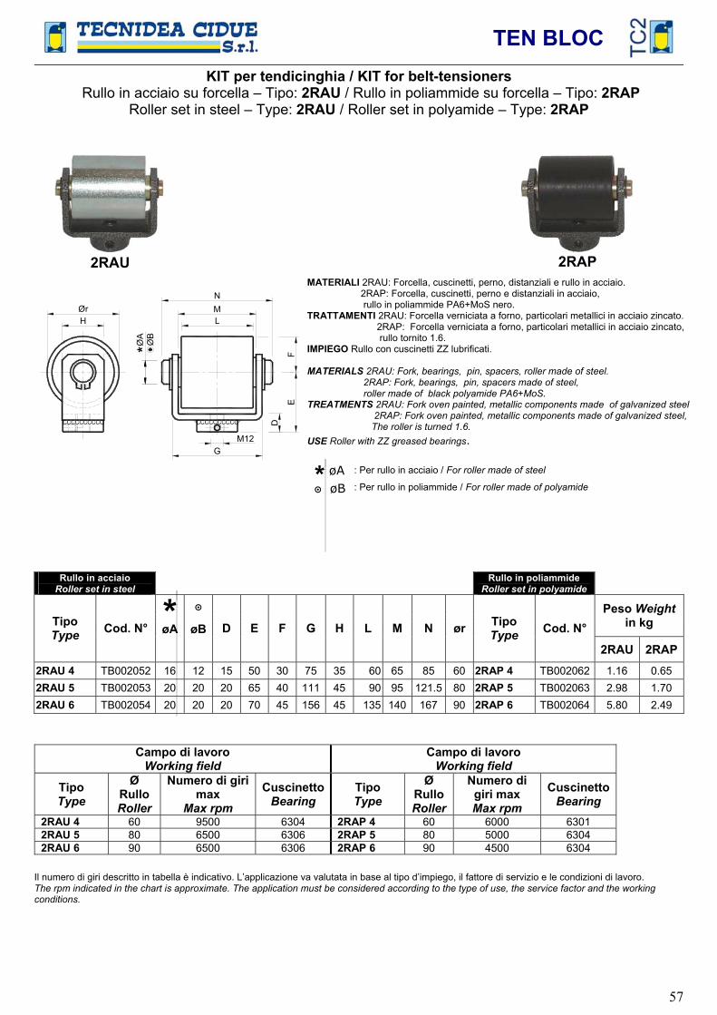
TEN BLOC
57
KIT per tendicinghia / KIT for belt-tensioners Rullo in acciaio su forcella – Tipo: 2RAU / Rullo in poliammide su forcella – Tipo: 2RAP
Roller set in steel – Type: 2RAU / Roller set in polyamide – Type: 2RAP
CCCCCCCCCCCCCCCCCCCC
GM12
D
EF
LMN
ØrH
ØA
ØB
*
MATERIALI 2RAU: Forcella, cuscinetti, perno, distanziali e rullo in acciaio. 2RAP: Forcella, cuscinetti, perno e distanziali in acciaio, rullo in poliammide PA6+MoS nero. TRATTAMENTI 2RAU: Forcella verniciata a forno, particolari metallici in acciaio zincato. 2RAP: Forcella verniciata a forno, particolari metallici in acciaio zincato, rullo tornito 1.6. IMPIEGO Rullo con cuscinetti ZZ lubrificati.
MATERIALS 2RAU: Fork, bearings, pin, spacers, roller made of steel. 2RAP: Fork, bearings, pin, spacers made of steel,
roller made of black polyamide PA6+MoS. TREATMENTS 2RAU: Fork oven painted, metallic components made of galvanized steel
2RAP: Fork oven painted, metallic components made of galvanized steel, The roller is turned 1.6. USE Roller with ZZ greased bearings.
* øA : Per rullo in acciaio / For roller made of steel
øB : Per rullo in poliammide / For roller made of polyamide
Rullo in acciaio Roller set in steel
Rullo in poliammide Roller set in polyamide
* Peso Weight in kg Tipo
Type Cod. N° øA øB D E F G H L M N ør TipoType Cod. N°
2RAU 2RAP2RAU 4 TB002052 16 12 15 50 30 75 35 60 65 85 60 2RAP 4 TB002062 1.16 0.65 2RAU 5 TB002053 20 20 20 65 40 111 45 90 95 121.5 80 2RAP 5 TB002063 2.98 1.70 2RAU 6 TB002054 20 20 20 70 45 156 45 135 140 167 90 2RAP 6 TB002064 5.80 2.49
Campo di lavoro Working field
Campo di lavoro Working field
TipoType
ØRulloRoller
Numero di giri max
Max rpm
CuscinettoBearing
TipoType
ØRulloRoller
Numero di giri max Max rpm
CuscinettoBearing
2RAU 4 60 9500 6304 2RAP 4 60 6000 6301 2RAU 5 80 6500 6306 2RAP 5 80 5000 6304 2RAU 6 90 6500 6306 2RAP 6 90 4500 6304
Il numero di giri descritto in tabella è indicativo. L’applicazione va valutata in base al tipo d’impiego, il fattore di servizio e le condizioni di lavoro. The rpm indicated in the chart is approximate. The application must be considered according to the type of use, the service factor and the working conditions.
2RAU 2RAP

TEN BLOC
58
Accessori TEN BLOC / Accessories TEN BLOCTipo: Forcella F – Type: Bracket F
a
d
g
eh
f
l M10
MATERIALI Forcella F10 / F11 / F12 / F13 / F15: alluminio ( ). Forcella F16: acciaio ( ). Perno in acciaio.
TRATTAMENTI Forcella in alluminio sabbiato o acciaio verniciato. Perno in acciaio zincato.
MATERIALS Fork F10 / F11 / F12 / F13 / F15: aluminium ( ). Fork F16 / F17: steel ( ). Pin made of steel.
TREATMENTS Fork made of sandblasted aluminium or painted steel. Pin made of galvanized steel.
TipoType Cod. N° a b c d e f g h l Peso Weight
in kg F10 TB001134 30 19 10.5 16 60 15 15 75 30 0.14 F11 TB001135 35 19 13 16 70 15 15 85 30 0.18 F12 TB001136 50 37 11.5 16 60 15 15 75 30 0.19 F13 TB001137 55 37 14 16 70 15 15 85 30 0.24 F14 TB001138 72 56 14 16 70 15 15 85 35 0.60 F15 TB001139 35 19 13 20 77.5 17.5 17.5 95 40 0.28 F16 TB001140 67 51 13 20 77.5 17.5 17.5 95 40 0.84
Tipo: Molla M / Type: Spring MMATERIALI Acciaio per molle. TRATTAMENTI Le molle sono fornite allo stato grezzo con trattamento di oleatura.
MATERIALS Steel for springs. TREATMENTS The springs are supplied at the raw state with oiling treatment.
L
Fb
Ø 2
3
Ø f
TipoType Cod. N° L b F øf Newton Peso Weight
in kgM10 TB001158 50 17 33 2.0 0 ÷ 100 0.013 M11 TB001159 50 18 32 2.3 0 ÷ 170 0.016 M12 TB001160 50 19 31 2.5 0 ÷ 250 0.019 M13 TB001161 75 35 40 3.0 0 ÷ 400 0.041 M14 TB001162 105 55 50 3.6 0 ÷ 700 0.075 M15 TB001163 130 85 45 4.0 0 ÷ 1000 0.113 M16 TB001164 155 110 45 4.5 0 ÷ 1500 0.162 M17 TB001165 160 110 50 4.7 0 ÷ 2000 0.179 M18 TB001166 205 155 50 5.2 0 ÷ 2500 0.268
Diagramma di carico-freccia molla: / Diagram of load-travel spring:
400
10 20 30 40
200
100
300
Freccia - Spring travel [mm]
M13
M12
M11
M10
Car
ico
- Loa
d [N
]
500
1000
1500
2000
2500
10 20 30 40 50Freccia - Spring travel [mm]
Car
ico
- Loa
d [N
]
M18
M17
M16
M15M14

TEN BLOC
59
Accessori TEN BLOC / Accessories TEN BLOCTipo: Colonna B / Type: Column BB8 – B8 L :
M10
A 16
BØ
18
2
Ø22
B 9 / B10/B11/B12/B13 :
B
A 15
M10 M10
Ø18
MATERIALI Acciaio TRATTAMENTI Zincatura elettrolitica MATERIALS Steel TREATMENTS Electrolytic zinc plated
TipoType Cod. N° A B Peso Weight
in kg B 8 TB001037 47 63 0.640 B 8L TB001036 62 78 0.850 B 9 TB001038 47 62 0.107 B10 TB001039 55 70 0.124 B11 TB001040 100 115 0.213 B12 TB001041 150 165 0.311 B13 TB001042 220 235 0.415
Le colonne B8 e B8 L sono realizzate con vite TCEI all’interno. The columns B8 e B8 L are made with a head cap screw inside.
Tipo: Colonna T / Type: Column T
B
A 15
M10
C Ø18
3
MATERIALI Acciaio TRATTAMENTI Zincatura elettrolitica MATERIALS Steel TREATMENTS Electrolytic zinc plated
TipoType Cod. N° A B C Peso Weight
in kg T 9 TB001047 47 62 M12 0.065 T10 TB001048 55 70 M12 0.078 T11 TB001049 100 115 M12 0.124 T12 TB001050 150 165 M12 0.170 T13 TB001051 220 235 M12 0.250 T14 TB001052 50 65 M 8 0.093 T15 TB001053 62 77 M 8 0.113
Tipo: Cilindro D / Type: Cilinder DD10 - D11 - D12 - D13 - D30:
Ø35
M
30 (P
F)
Ø24
M30
(PF)A 12
B
12.5
MATERIALI Acciaio TRATTAMENTI Zincatura elettrolitica MATERIALS Steel TREATMENTS Electrolytic zinc plated
TipoType Cod. N° A B Peso Weight
in kg D10 TB001015 25 37 0.095 D11 TB001016 50 62 0.192 D12 TB001017 75 87 0.289 D13 TB001018 100 112 0.388 D30 TB001030 35 47 0.133

TEN BLOC
60
Accessori TEN BLOC / Accessories TEN BLOCTipo: Cilindro D / Type: Cilinder DD20 – D21
A
B
3
ØC
8
M30
(PF)
Ø24
12
Ø35
32
MATERIALI Acciaio TRATTAMENTI Zincatura elettrolitica MATERIALS Steel TREATMENTS Electrolytic zinc plated
TipoType Cod. N° A B C Peso Weight
in kg D20 TB001023 34 37 / 0.092 D21 TB001024 67 70 12.5 0.146
Tipo: Tappo Z10 / Type: Stopper Z10Cod. N° TB001008MATERIALI Acciaio TRATTAMENTI Zincatura elettrolitica MATERIALS Steel TREATMENTS Electrolytic zinc plated
32 1612.5 3.5
Ø24
10
M30
(PF)
Tipo: Tappo Z11 / Type: Stopper Z11Cod. N° TB001009 MATERIALI Acciaio TRATTAMENTI Zincatura elettrolitica MATERIALS Steel TREATMENTS Electrolytic zinc plated
32 22.512.5 10
M30
(PF)
Ø13
Tipo: Vite UD / Type: Screw UD
M8
L
Ø7
20 6
MATERIALI Acciaio TRATTAMENTI Zincatura elettrolitica MATERIALS Steel TREATMENTS Electrolytic zinc plated
TipoType Cod. N° L Peso Weight
in kg UD 10 TB001246 60 0.025 UD 11 TB001247 95 0.035 UD 12 TB001248 120 0.043 UD 13 TB001249 130 0.047 UD 14 TB001250 140 0.051 UD 15 TB001251 150 0.055
Tipo: Corpo TN / Type: Body TNCod. N° TB001001 MATERIALI Alluminio / MATERIALS AluminiumTRATTAMENTI Sabbiatura / TREATMENTS Sandblasted
65
60
405012
.5
9
Ø18 7.5
7.5 35
4010 10
M30 (PF)
Pressofusione in alluminio con bronzina già incorporata Die casting in aluminium with bushing inside Peso / Weight: 0.20 kg
Tipo: Corpo TB / Type: Body TBCod. N° TB001002 MATERIALI Alluminio / MATERIALS AluminiumTRATTAMENTI Sabbiatura / TREATMENTS Sandblasted
65
60
405012
.5
12.5
9
Ø18 7.5
7.5 35
M8
4010 10
M30 (PF)
Pressofusione in alluminio con bronzina già incorporata Die casting in aluminium with bushing inside Peso / Weight: 0.20 kg
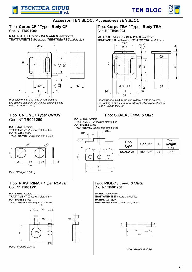
TEN BLOC
61
Accessori TEN BLOC / Accessories TEN BLOCTipo: Corpo CF / Type: Body CFCod. N° TB001000 MATERIALI Alluminio / MATERIALS AluminiumTRATTAMENTI Sabbiatura / TREATMENTS Sandblasted
65
60
405012
.5
9
Ø17 7.5
7.5 35
4010 10
Ø28
Pressofusione in alluminio senza bronzina Die casting in aluminium without bushing insidePeso / Weight: 0.20 kg
Tipo: Corpo TBA / Type: Body TBACod. N° TB001003
MATERIALI Alluminio / MATERIALS AluminiumTRATTAMENTI Sabbiatura / TREATMENTS Sandblasted
65
60
40
5012
.5
12.5
9
7.5
7.5 35
4010 10
5
Ø50Ø18
M30 (PF)
Pressofusione in alluminio con collare in ottone esterno Die casting in aluminium with external collar made of brass Peso / Weight: 0.20 kg
Tipo: UNIONE / Type: UNIONCod. N° TB001260
MATERIALI Acciaio TRATTAMENTI Zincatura elettrolitica MATERIALS Steel TREATMENTS Electrolytic zinc plated
100 60 20 20 3
35
Ø31 Ø31
Peso / Weight: 0.38 kg
Tipo: SCALA / Type: STAIRMATERIALI Acciaio TRATTAMENTI Zincatura elettrolitica MATERIALS Steel TREATMENTS Electrolytic zinc plated
9060= =
2515
510
38 = =
Ø11Ø12.5
TipoType Cod. N° A
PesoWeight in kg
SCALA 25 TB001271 25 0.14
Tipo: PIASTRINA / Type: PLATECod. N° TB001231
MATERIALI Acciaio TRATTAMENTI Zincatura elettrolitica MATERIALS Steel TREATMENTS Electrolytic zinc plated
Ø18
M10
30
7.5 25 7.5
M6 M6
Peso / Weight: 0.10 kg
Tipo: PIOLO / Type: STAKECod. N° TB001236
MATERIALI Acciaio TRATTAMENTI Zincatura elettrolitica MATERIALS Steel TREATMENTS Electrolytic zinc plated
50
1238
M10
Peso / Weight: 0.03 kg

TEN BLOC
62
Esempi di applicazione TEN BLOC / Examples of application TEN BLOC
=
Fig. 1 Tendicatena / Chain Tensioner
Fig. 2 Tendicatena interno / Internal Chain Tensioner
Fig. 3 Tendicatena per movimenti reversibili Double Chain Tensioner for reversibile movements
Fig. 4 Tendicatena in tiro / Pull Chain Tensioner
Fig. 5 Tendicatena a doppia guida per elevati recuperi e per interassi variabili Double chain tensioner guide for high recoveries and variable distance between centres
Fig. 6 Tenditore uni-direzionale per trasportatori One-direction tensioner for conveyors
=
Fig. 7 Tendicatena per alte velocità Chiantensioner for high speed
=
Fig. 8 Tendicinghia / Belt Tensioner