BRAINY - Quality Gate Automationbenincauk.co.uk/wp-content/uploads/tech_brainy.pdfl8542910 04/2012...
12
L8542910 04/2012 rev. 2 UNIONE NAZIONALE COSTRUTTORI AUTOMATISMI PER CANCELLI, PORTE SERRANDE ED AFFINI BRAINY
Transcript of BRAINY - Quality Gate Automationbenincauk.co.uk/wp-content/uploads/tech_brainy.pdfl8542910 04/2012...
L854291004/2012 rev. 2
UNIONE NAZIONALE COSTRUTTORIAUTOMATISMI PER CANCELLI, PORTE
SERRANDE ED AFFINI
BRAINY
2
111098765 13124
3332
3130
2928
2735
3436
2625
2423
2221
20
F2
115/230Vac50/60Hz
NGND
L
RADIO
TLS
Encoder M1
24Vac500mA max
AUX1
AUX2
CO
M
M1
C
CO
M
M2
C
M1
191817161514
3837
NL
F1
LAMP230Vac
Encoder M2
M2
8k2
DAS
SWO-M1 (Open)SWC-M1 (Close)SWO-M2 (Open)SWC-M2 (Close)
P.P.
COM
COM
PED.OPENCLOSE
PHOT
PHOT (Close)STOP
SHIELD
ANT
AN
T
SCA 24Vac3W max24Vac
1A max
191817161514
Lock12Vac10W
191817161514 31 32 3331292827 31 32 3331292827
24Vac 24VacCOMNCNO
RX1TX1
SCA PHOTO-TEST
191817161514
24Vac 24VacCOMNCNO
RX2TX2
J2 DAS Open
DAS N.C.
J2 DASClose
DAS 8K2
DAS
____Code
Encoder M1
M1
+ s -
Encoder M2
M2
+ s -
3+3 x 0.5mm2
max 10m
U11
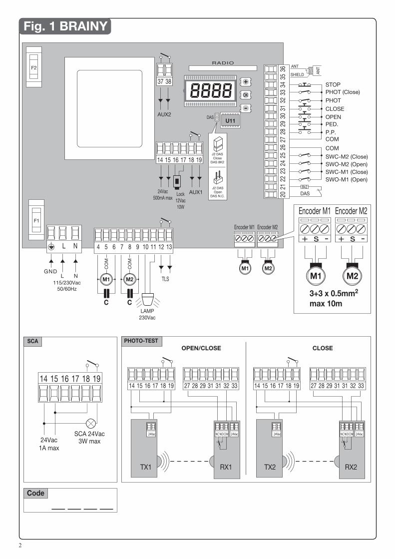
Fig. 1 BRAINY
OPEN/CLOSE CLOSE
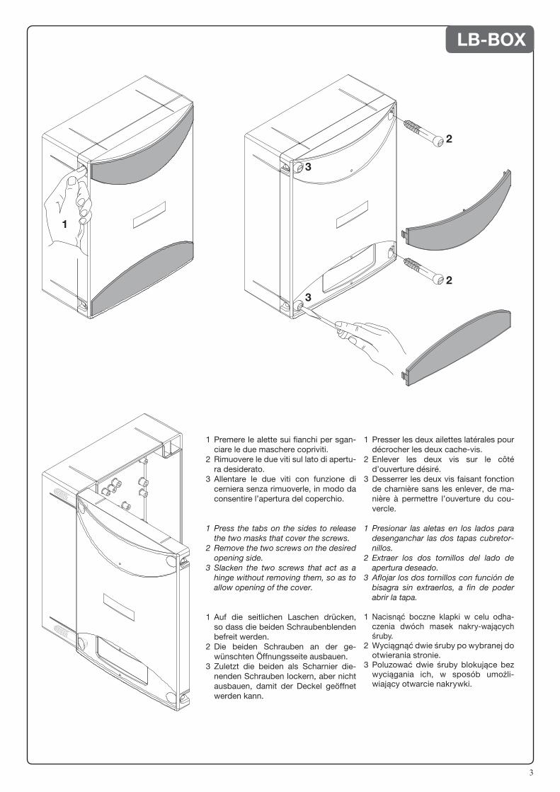
3
LB-BOX
12
WARNINGSThis manual has been especially written to be use by qualified fitters.
None of the information provide in this manual can be consi-dered as being of interest for the end users.
Preserve this manual for future needs.
The technician has to furnish all the information related to the step by step function, the manual and the emergency function of the operator, and to deliver the manual to the final user.
•Foresee on the supply net an onnipolar switch or selector with distance of the contacts equal or superior to 3 mms.
Verify that of the electrical system there is an awry differential interrupter and overcurrent protection.
Some typologies of installation require the connection of the shutter to be link at a conductive mass of the ground according to the regulations in force.
The electrical installation and the operating logic must comply with the regulations in force.
The leads fed with different voltages must be physically separate, or they must be suitably insulated with additional insulation of at least 1 mm.
The leads must be secured with an additional fixture near the terminals.
During installation, maintenance and repair, interrupt the power supply before opening the lid to access the electrical parts
Check all the connections again before switching on the power.
The unused N.C. inputs must be bridged.
The descriptions and the present illustrations in this manual are not binding. Leaving the essential characteristics of the product unchanged, the manufacturer reserves himself the right to bring any change of technical, constructive or com-mercial character without undertaking himself to update the present publication.
EC Declaration of conformityDeclaration pursuant to Directives 2004/108/EC(EMC); 2006/95/EC(LVD)
Manufacturer:Automatismi Benincà SpAAddress:Via Capitello, 45 - 36066 Sandrigo (VI) - ItalyDeclares that the product:Command central for 1/2 230 Vac motor, for single or sliding doors: BRAINYis compliant with the conditions of the following EC Directives: • DIRECTIVE 2004/108/EC OF THE EUROPEAN PARLIAMENT AND COUNCIL of December 15 2004 regarding the approximation of the legislations of the member States relative to electromagnetic compatibility and that repeals directive 89/336/CEE, according to the following concurred norms: EN 61000-6-2:2005, EN 61000-6-3:2007.• DIRECTIVE 2006/95/EC OF THE EUROPEAN PARLIAMENT AND THE COUNCIL of December 12 2006 concer-ning the approximation of the legislations of the member States relative to electrical material destined to be used within certain voltage limits, according to the following concurred regulations: EN 60335-1:2002 + A1:2004 + A11:2004 + A12:2006 + A2:2006 + A13:2008; EN 60335-2-103:2003.if applicable :• DIRECTIVE 1999/5/EC OF THE EUROPEAN PARLIAMENT AND THE COUNCIL of March 9 1999 regarding radio devices and terminal and telecommunications devices and the reciprocal recognisances of their conformity, according to the following concurred regulations: ETSI EN 301 489-3 V1.4.1 (2002) + ETSI EN 301 489-1 V1.4.1 (2002) + ETSI EN 300 220-3 V1.1.1 (2000) + EN 60950-1 (2001)
Benincà Luigi, Legal manager.Sandrigo, 02/11/2010.
13
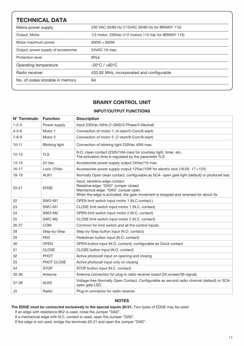
BRAINY CONTROL UNIT
INPUT/OUTPUT FUNCTIONS
N° Terminals Function description
1-2-3 Power supply Input 230Vac 50Hz (1-GND/2-Phase/3-Neutral)
4-5-6 Motor 1 Connection of motor 1: (4-start/5-Com/6-start)
7-8-9 Motor 2 Connection of motor 2: (7-start/8-Com/9-start)
10-11 Blinking light Connection of blinking light 230Vac 40W max.
12-13 TLSN.O. clean contact (230V/16A max) for courtesy light, timer, etc. The activation time is regulated by the parameter TLS
14-15 24 Vac Accessories power supply output 24Vac/1A max.
16-17 Lock 12Vdc Accessories power supply output 12Vac/10W for electric lock (16:0V, 17:+12V)
18-19 AUX1 Normally Open clean contact, configurable as SCA- open gate light (default) or photocell test.
20-21 EDGE
Input, sensitive edge contact Resistive edge: “DAS” Jumper closedMechanical edge: “DAS” Jumper open When the edge is activated, the gate movement is stopped and reversed for about 3s.
22 SWO-M1 OPEN limit switch input motor 1 (N.C contact.)
23 SWC-M1 CLOSE limit switch input motor 1 (N.C. contact)
24 SWO-M2 OPEN limit switch input motor 2 (N.C. contact)
25 SWC-M2 CLOSE limit switch input motor 2 (N.C. contact)
26-27 COM Common for limit switch and all the control inputs.
28 Step-by-Step Step-by-Step button input (N.O. contact)
29 PED Pedestrian button input (N.O. contact)
30 OPEN OPEN button input (N.O. contact), configurable as Clock contact
31 CLOSE CLOSE button input (N.O. contact)
32 PHOT Active photocell input on opening and closing
33 PHOT CLOSE Active photocell input only on closing
34 STOP STOP button input (N.C. contact)
35-36 Antenna Antenna connection for plug-in radio receiver board (35-screen/36-signal).
37-38 AUX2Voltage-free Normally Open Contact. Configurable as second radio channel (default) or SCA-open gate LED.
J3 Radio Plug-in connector for radio receiver.
NOTESThe EdGE must be connected exclusively to the special inputs 20/21. Two types of EDGE may be used: If an edge with resistance 8K2 is used, close the Jumper “DAS”. If a mechanical edge with N.C. contact is used, open the Jumper “DAS”. If the edge is not used, bridge the terminals 20-21 and open the Jumper “DAS”.
TEChNICAL dATAMains power supply 230 VAC 50/60 Hz (115VAC 50/60 Hz for BRAINY 115)
Output, Motor 1/2 motor, 230Vac (1/2 motors 115 Vac for BRAINY 115)
Motor maximum power 600W + 600W
Output, power supply of accessories 24VAC 1A max.
Protection level IP54
Operating temperature -20°C / +60°C
Radio receiver 433,92 MHz, incorporated and configurable
No. of codes storable in memory 64
14
TO ChECK CONNECTIONS:1) Cut-off power supply.2) Manually release the wings, move them to approx. half-stroke and lock them again.3) Reset power supply.4) Send a step-by-step control signal by pressing the button or the remote control key.5) The wings should start an opening movement. If this is not the case, invert the movement wires of the motor. (4<>6 for motor M1, and 7<>9 for motor M2) and the relevant limit
switch inputs (22<>23 for motor M1, and 24<>25 for motor M2).
PROGRAmmINGThe programming of the various functions of the control unit is carried out using the LCD display on the control unit and setting the desired values in the programming menus described below.The parameters menu allows you to assign a numerical value to a function, in the same way as a regulating trimmer.The logic menu allows you to activate or deactivate a function, in the same way as setting a dip-switch.Other special functions follow the parameters and logic menus and may vary depending on the type of control unit or the software release.
TO ACCESS PROGRAmmING1 – Press the button <PG>, the display goes to the first menu, Parameters “PAR”. 2 – With the <+> or <-> button, select the menu you want.3- Press the button <PG>, the display shows the first function available on the menu.4 - With the <+> or <-> button, select the function you want.5 - Press the button <PG>, the display shows the value currently set for the function selected.6 - With the <+> or <-> button, select the value you intend to assign to the function.7 - Press the button <PG>, the display shows the signal “PRG” which indicates that programming has been completed.
NOTESPressing <-> with the display turned off means an impulse of P.P. Simultaneously pressing <+> and <-> from inside a function menu allows you to return to the previous menu without making any changes. Hold down the <+> key or the <-> key to accelerate the increase/decrease of the values.After waiting 30s the control unit quits programming mode and switches off the display.
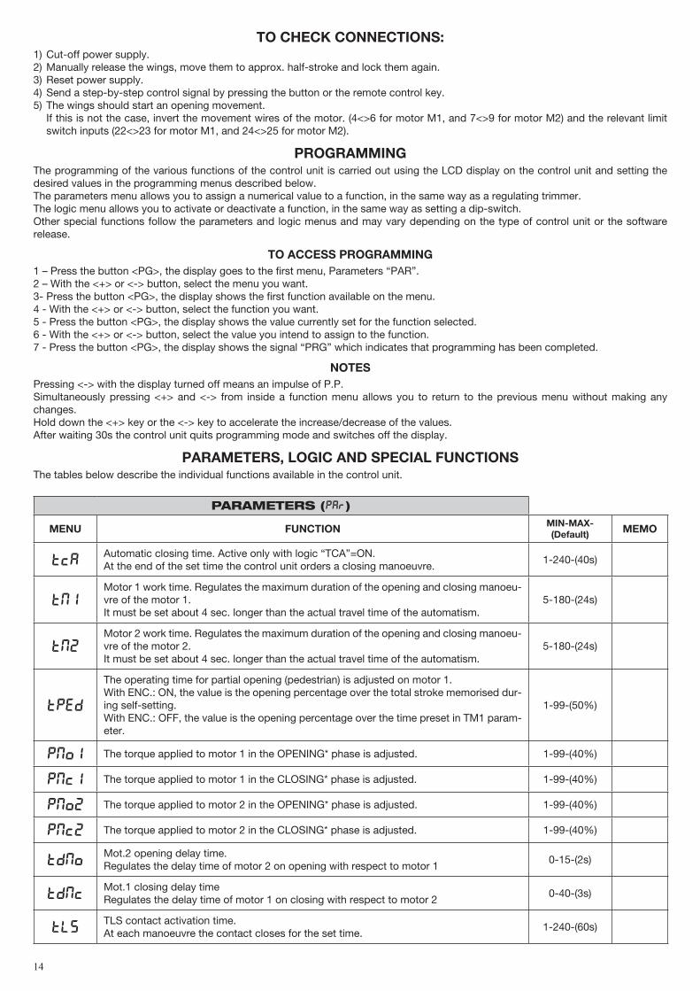
PARAmETERS, LOGIC ANd SPECIAL FUNCTIONS The tables below describe the individual functions available in the control unit.
PARAMETERS (PAR)
mENU FUNCTION mIN-mAX-(default) mEmO
TCAAutomatic closing time. Active only with logic “TCA”=ON.At the end of the set time the control unit orders a closing manoeuvre.
1-240-(40s)
TM1Motor 1 work time. Regulates the maximum duration of the opening and closing manoeu-vre of the motor 1. It must be set about 4 sec. longer than the actual travel time of the automatism.
5-180-(24s)
TM2Motor 2 work time. Regulates the maximum duration of the opening and closing manoeu-vre of the motor 2. It must be set about 4 sec. longer than the actual travel time of the automatism.
5-180-(24s)
TPed
The operating time for partial opening (pedestrian) is adjusted on motor 1. With ENC.: ON, the value is the opening percentage over the total stroke memorised dur-ing self-setting.With ENC.: OFF, the value is the opening percentage over the time preset in TM1 param-eter.
1-99-(50%)
PMo1 The torque applied to motor 1 in the OPENING* phase is adjusted. 1-99-(40%)
PMC1 The torque applied to motor 1 in the CLOSING* phase is adjusted. 1-99-(40%)
PMo2 The torque applied to motor 2 in the OPENING* phase is adjusted. 1-99-(40%)
PMC2 The torque applied to motor 2 in the CLOSING* phase is adjusted. 1-99-(40%)
TDMoMot.2 opening delay time.Regulates the delay time of motor 2 on opening with respect to motor 1
0-15-(2s)
TDMCMot.1 closing delay timeRegulates the delay time of motor 1 on closing with respect to motor 2
0-40-(3s)
TLSTLS contact activation time.At each manoeuvre the contact closes for the set time.
1-240-(60s)
15
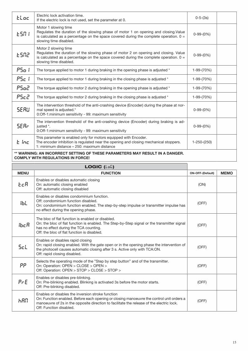
TLOcElectric lock activation time. If the electric lock is not used, set the parameter at 0.
0-5-(3s)
TsM1
Motor 1 slowing timeRegulates the duration of the slowing phase of motor 1 on opening and closing.Value is calculated as a percentage on the space covered during the complete operation. 0 = slowing time disabled.
0-99-(0%)
TsM2
Motor 2 slowing timeRegulates the duration of the slowing phase of motor 2 on opening and closing. Value is calculated as a percentage on the space covered during the complete operation. 0 = slowing time disabled.
0-99-(0%)
Pso1 The torque applied to motor 1 during braking in the opening phase is adjusted * 1-99-(70%)
PsC1 The torque applied to motor 1 during braking in the closing phase is adjusted * 1-99-(70%)
Pso2 The torque applied to motor 2 during braking in the opening phase is adjusted * 1-99-(70%)
PsC2 The torque applied to motor 2 during braking in the closing phase is adjusted * 1-99-(70%)
SeaUThe intervention threshold of the anti-crashing device (Encoder) during the phase at nor-mal speed is adjusted.*0:Off-1:minimum sensitivity - 99: maximum sensitivity
0-99-(0%)
SEARThe intervention threshold of the anti-crashing device (Encoder) during braking is ad-justed *.0:Off-1:minimum sensitivity - 99: maximum sensitivity
0-99-(0%)
tincThis parameter is enabled only for motors equipped with Encoder.The encoder inhibition is regulated near the opening and closing mechanical stoppers.1: minimum distance – 250: maximum distance
1-250-(250)
** WARNING: AN INCORRECT SETTING OF ThESE PARAmETERS mAY RESULT IN A dANGER. COmPLY WITh REGULATIONS IN FORCE!
LOGIC (LOG)mENU FUNCTION ON-OFF-(default) mEmO
TCAEnables or disables automatic closingOn: automatic closing enabledOff: automatic closing disabled
(ON)
IbL
Enables or disables condominium function. Off: condominium function disabled. On: condominium function enabled. The step-by-step impulse or transmitter impulse has no effect during the opening phase.
(OFF)
IbCA
The bloc of flat function is enabled or disabled. On: the bloc of flat function is enabled. The Step-by-Step signal or the transmitter signal has no effect during the TCA counting.Off: the bloc of flat function is disabled.
(OFF)
SCL
Enables or disables rapid closingOn: rapid closing enabled. With the gate open or in the opening phase the intervention of the photocell causes automatic closing after 3 s. Active only with TCA:ON.Off: rapid closing disabled.
(OFF)
PPSelects the operating mode of the ”Step by step button” and of the transmitter.On: Operation: OPEN > CLOSE > OPEN >Off: Operation: OPEN > STOP > CLOSE > STOP >
(OFF)
PREEnables or disables pre-blinking.On: Pre-blinking enabled. Blinking is activated 3s before the motor starts.Off: Pre-blinking disabled.
(OFF)
HAM
Enables or disables the inversion stroke function On: Function enabled. Before each opening or closing manoeuvre the control unit orders a manoeuvre of 2s in the opposite direction to facilitate the release of the electric lock.Off: Function disabled.
(OFF)

16
BLC
Enables or disables the block maintaining function.Recommended for hydraulic motors to keep the leaf resting against the mechanical stop block.On: Block maintaining function enabled. Every 2 hours the control unit makes a closing manoeuvre with a duration of about 3s to keep the leaf in contact.Off: Block maintaining function disabled.
(OFF)
SPN
Enables or disables starting torque function. On: Starting torque enabled. At the start of each manoeuvre for 2s the motor operates at maximum torque.Off: Starting torque disabled.
(ON)
LTCASelects the operating mode of the blinking light during the time TCAOn: Blinking light on during TCAOff: Blinking light off during TCA
(OFF)
CLOC
Selects the mode of the OPEN inputOn: OPEN input with CLOCK function. To be used for connection to a timer for timed opening/closing. (Contact CLOSED- gate open, Contact open, normal operation).
(OFF)
htr
Enables or disables Man present function. On: Man Present operation. The OPEN/CLOSE buttons must be held down during the whole manoeuvre. Off: Automatic operation.
(OFF)
1mot
Select the 1/2 motors operating mode:On: only one motor (motor 1) active. Function to be used in the following cases: - for single motor, to connect M1:4-5-6.- for two syncronized motors (for instance overhead door), to connect M1:4-5-6 and M2:7-
8-9. You need to regulate the parameters related to the motor 1, the limit switch entries M2 are disarmed (not activate).
Off: Both motors operating.
(OFF)
not
The calculation of residual operating time is activated or deactivated in the event of partial operations:On: Calculation of deactivated time. In case of partial operations, the operating time is reset. The following operation restarts for the entire time preset by parameter TM1/TM2.Off: Calculation of activated time. In case of partial operations, the operating time is sto-red in memory and then subtracted from the TM1/TM2 parameter value in the following operation.
(ON)
ENCThe Encoder is enabled or disabled. See section “ TYPES OF INSTALLATIONS”On: Encoder enabled – The anti-crash sensor is activated.Off: Encoder disabled – The anti-crash sensor is deactivated.
(OFF)
Cvar
The code programmable transmitters is enabled or disabled. On: Radio receiver enabled only for rolling-code transmitters. Off: Receiver enabled for rolling-code and programmable code transmitters (self-learning and Dip Switch).
(OFF)
mloc
Selects the type of electric lock used.On: Magnetic electric lock, normally fed at 12Vdc.Before each opening manoeuvre the power supply is interrupted for the time set by the parameter TLOC.Off: Electric lock with latch, normally not fed.Before each opening manoeuvre power is fed at 12Vdc for the time set by the parameter TLOC.
(OFF)
TRKThe check for integrity of TRIAC is enabled or disabled.On: Activated check: if TRAC is faulty, the motor does not start.Off: the TRIAC is not checked.
(OFF)
TST1
The test of photocells to PHOT O input is enabled or disabled.On: Test is enabled. If the test is negative, no operation is performed. See Fig.1 “PHOTO TEST”.Off: Test is disabled.
(OFF)
TST2
The test of photocells to PHOT C input is enabled or disabled.On: Test is enabled. If the test is negative, no operation is performed. See Fig.1 “PHOTO TEST”.Off: Test is disabled.
(OFF)
17
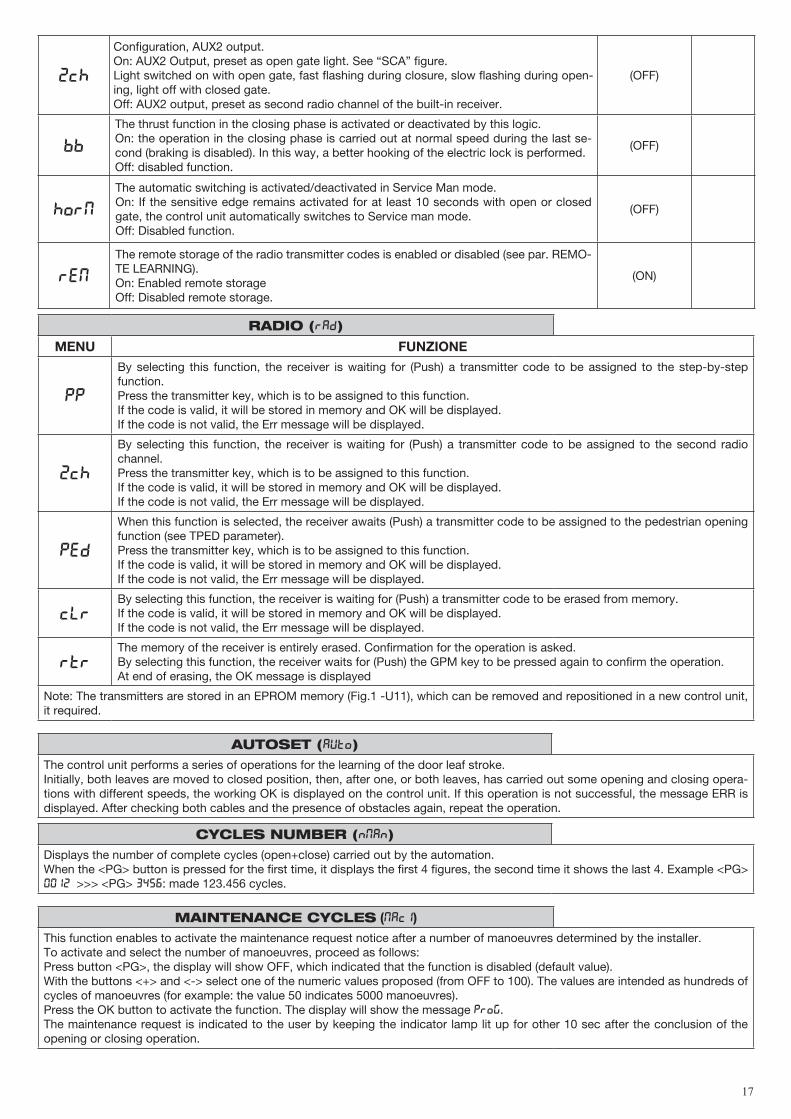
2CH
Configuration, AUX2 output.On: AUX2 Output, preset as open gate light. See “SCA” figure.Light switched on with open gate, fast flashing during closure, slow flashing during open-ing, light off with closed gate.Off: AUX2 output, preset as second radio channel of the built-in receiver.
(OFF)
BB
The thrust function in the closing phase is activated or deactivated by this logic. On: the operation in the closing phase is carried out at normal speed during the last se-cond (braking is disabled). In this way, a better hooking of the electric lock is performed.Off: disabled function.
(OFF)
Horm
The automatic switching is activated/deactivated in Service Man mode.On: If the sensitive edge remains activated for at least 10 seconds with open or closed gate, the control unit automatically switches to Service man mode.Off: Disabled function.
(OFF)
REM
The remote storage of the radio transmitter codes is enabled or disabled (see par. REMO-TE LEARNING).On: Enabled remote storage Off: Disabled remote storage.
(ON)
RADIO (RAD)
mENU FUNZIONE
PP
By selecting this function, the receiver is waiting for (Push) a transmitter code to be assigned to the step-by-step function.Press the transmitter key, which is to be assigned to this function.If the code is valid, it will be stored in memory and OK will be displayed.If the code is not valid, the Err message will be displayed.
2Ch
By selecting this function, the receiver is waiting for (Push) a transmitter code to be assigned to the second radio channel.Press the transmitter key, which is to be assigned to this function.If the code is valid, it will be stored in memory and OK will be displayed.If the code is not valid, the Err message will be displayed.
ped
When this function is selected, the receiver awaits (Push) a transmitter code to be assigned to the pedestrian opening function (see TPED parameter).Press the transmitter key, which is to be assigned to this function.If the code is valid, it will be stored in memory and OK will be displayed.If the code is not valid, the Err message will be displayed.
CLRBy selecting this function, the receiver is waiting for (Push) a transmitter code to be erased from memory.If the code is valid, it will be stored in memory and OK will be displayed.If the code is not valid, the Err message will be displayed.
RTRThe memory of the receiver is entirely erased. Confirmation for the operation is asked.By selecting this function, the receiver waits for (Push) the GPM key to be pressed again to confirm the operation.At end of erasing, the OK message is displayed
Note: The transmitters are stored in an EPROM memory (Fig.1 -U11), which can be removed and repositioned in a new control unit, it required.
AUTOSET (AUTO)The control unit performs a series of operations for the learning of the door leaf stroke.Initially, both leaves are moved to closed position, then, after one, or both leaves, has carried out some opening and closing opera-tions with different speeds, the working OK is displayed on the control unit. If this operation is not successful, the message ERR is displayed. After checking both cables and the presence of obstacles again, repeat the operation.
CYCLES NUMBER (Nman)Displays the number of complete cycles (open+close) carried out by the automation. When the <PG> button is pressed for the first time, it displays the first 4 figures, the second time it shows the last 4. Example <PG> 0012 >>> <PG> 3456: made 123.456 cycles.
MAINTENANCE CYCLES (maci)
This function enables to activate the maintenance request notice after a number of manoeuvres determined by the installer. To activate and select the number of manoeuvres, proceed as follows: Press button <PG>, the display will show OFF, which indicated that the function is disabled (default value). With the buttons <+> and <-> select one of the numeric values proposed (from OFF to 100). The values are intended as hundreds of cycles of manoeuvres (for example: the value 50 indicates 5000 manoeuvres). Press the OK button to activate the function. The display will show the message PROG. The maintenance request is indicated to the user by keeping the indicator lamp lit up for other 10 sec after the conclusion of the opening or closing operation.

18
RESET (RES)RESET of the control unit. ATTENTION!: Returns the control unit to the default values.Pressing the <PG> button for the first time causes blinking of the letters RES, pressing the <PG> button again resets the control unit. Note: The transmitters are not erased from the receiver nor is the access password. All the logics and all the parameters are brought back to default values, it is therefore necessary to repeat the autoset procedure.
PROTECTION CODE (CODE)It allows to type in an access protection code to the programming of the control unit.A four-character alphanumeric code can be typed in by using the numbers from 0 to 9 and the letters A-B-C-D-E-F.The default value is 0000 (four zeros) and shows the absence of a protection code.While typing in the code, this operation can be cancelled at any moment by pressing keys + and – simultaneously. Once the password is typed in, it is possible to act on the control unit by entering and exiting the programming mode for around 10 minutes in order to allow adjustments and tests on functions.By replacing the 0000 code with any other code, the protection of the control unit is enabled, thus preventing the access to any other menu. If a protection code is to be typed in, proceed as follows:- select the Code menu and press OK.- the code 0000 is shown, also in the case a protection code has been previously typed in.- the value of the flashing character can be changed with keys + and -.- press OK to confirm the flashing character, then confirm the following one. - after typing in the 4 characters, a confirmation message “CONF” appears.- after a few seconds, the code 0000 appears again- the previously stored protection code must be reconfirmed in order to avoid any accidental typing in.If the code corresponds to the previous one, a confirmation message “OK” appears.The control unit automatically exits the programming phase. To gain access to the Menus again, the stored protection code must be typed in.ImPORTANT: TAKE NOTE of the protection code and KEEP IT IN A SAFE PLACE for future maintenance operations. To remove a code from a protected control unit it is necessary to enter into programming with the password and bring the code back to the 0000 default value. IF YOU LOOSE ThE COdE, PLEASE CONTACT ThE AUThORISEd SERVICE CENTER FOR ThE TOTAL RESET OF ThE CON-TROL UNIT.
BRAKINGWith the ENC=OFF logics, braking is given by the TSM1/TSM2 parameter value referred to the TM1/TM2 operating time. For example, if the operation of motor 1 lasts 20 seconds and TM1=24s and TSM1=8 are preset, 4 s braking will result (20-(24-8).
With ENC=ON logics, braking is calculated as a percentage on the space covered during the complete operation. If, for example, TSM1=20, 20% of the operation will be slow down.
FUSES
F1: F6.3A (230VAC) / F10A (115VAC) – Motor protection F2: T315mA (230VAC) – T500mA (115VAC) – Protection for primary transformer
TRANSmITTER REmOTE LEARNINGIf the transmitter code is already stored in the receiver, the remote radio learning can be carried out (without accessing the control unit).IMPORTANT: The procedure should be carried out with gate in the opening phase, during the TCA dwell time.Proceed as follows:1 Press the hidden key of the transmitter, the code of which has already been stored in memory.2 Within 5 seconds, press the already memorised transmitter key corresponding to the channel to be matched to the new transmitter. The flashing light switches on.3 Within 10 seconds, press the hidden key of the new transmitter.4 Within 5 seconds, press the key of the new transmitter to be matched to the channel selected at item 2. The flashing light switches off.5 The receiver stores the new transmitter code and exits from the programming mode immediately.
TYPES OF INSTALLATION
AUTOmATIC SYSTEm WITh ENCOdERStart a self-test operation, as indicated in the AUTO Menu.At completion of the lelf-learning, the value of all torques and the TDMO/TDMC value are preset by the control unit.If an obstacle is present, the Encoder acts as anti-crash sensor. Its sensitivity is adjusted by SEAV and SEAR parameters.
AUTOmATIC SYSTEm WITh ELECTROmEChANIC LImIT SWITChESIn this operating mode, the NOT=ON logics and the ENC=OFF logics must be preset.All parameters must be preset manually. In particular, values of TM1/TM2 must be some seconds higher than the actual operating time.
AUTOmATIC SYSTEm WITh ELECTROmEChANIC LImIT SWITChES ANd WIThOUT ENCOdERIn this operating mode, the NOT=OFF logics and the ENC=OFF logics must be preset.All parameters must be preset manually. In particular, values of TM1/TM2 must be some seconds higher than the actual operating time.
19
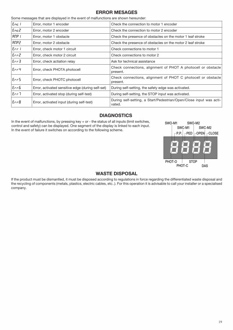
ERROR mESAGESSome messages that are displayed in the event of malfunctions are shown hereunder:
Enc1 Error, motor 1 encoder Check the connection to motor 1 encoder
Enc2 Error, motor 2 encoder Check the connection to motor 2 encoder
Amp1 Error, motor 1 obstacle Check the presence of obstacles on the motor 1 leaf stroke
Amp2 Error, motor 2 obstacle Check the presence of obstacles on the motor 2 leaf stroke
Err1 Error, check motor 1 circuit Check connections to motor 1
Err2 Error, check motor 2 circuit Check connections to motor 2
Err3 Error, check actiation relay Ask for technical assistance
Err4 Error, check PHOTA photocellCheck connections, alignment of PHOT A photocell or obstacle present.
Err5 Error, check PHOTC photocellCheck connections, alignment of PHOT C photocell or obstacle present.
Err6 Error, activated sensitive edge (during self-set) During self-setting, the safety edge was activated.
Err7 Error, activated stop (during self-test) During self-setting, the STOP input was activated.
Err8 Error, activated input (during self-test)During self-setting, a Start/Pedestrian/Open/Close input was acti-vated.
dIAGNOSTICSIn the event of malfunctions, by pressing key + or - the status of all inputs (limit switches, control and safety) can be displayed. One segment of the display is linked to each input. In the event of failure it switches on according to the following scheme.
PHOT-O
SWC-M1
STOP
SWO-M1 SWO-M2SWC-M2
PHOT-C DAS
P.P. PED OPEN CLOSE
WASTE dISPOSALIf the product must be dismantled, it must be disposed according to regulations in force regarding the differentiated waste disposal and the recycling of components (metals, plastics, electric cables, etc..). For this operation it is advisable to call your installer or a specialised company.

AUTOmATISmI BENINCà SpA - Via Capitello, 45 - 36066 Sandrigo (VI) - Tel. 0444 751030 r.a. - Fax 0444 759728