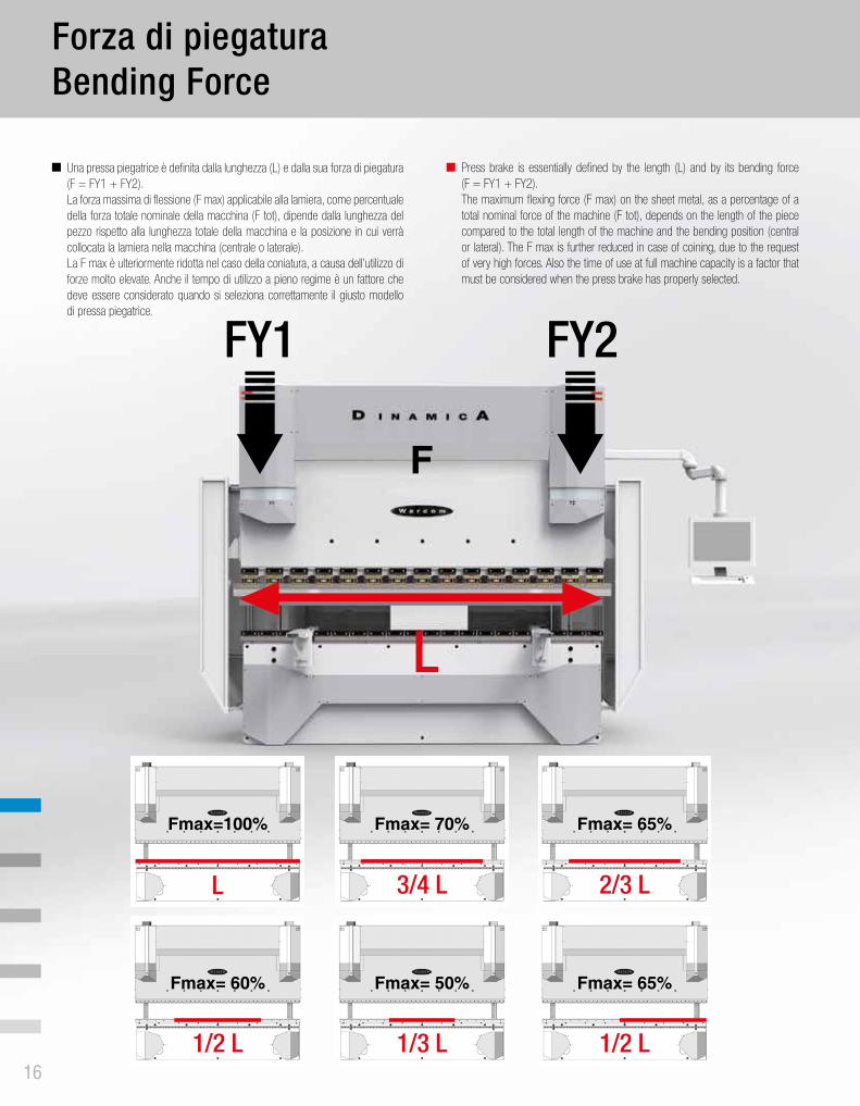
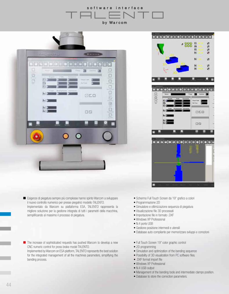
BENDING - rein-tech.in · fabbro in una realtà artigianale per produrre macchine per la...
68
COLLECTION BENDING COLLEZIONE PIEGATURA COLLECTION BENDING COLLEZIONE PIEGATURA
Transcript of BENDING - rein-tech.in · fabbro in una realtà artigianale per produrre macchine per la...
COLLECTION BENDINGCOLLEZIONE PIEGATURA
IIa edi
zion
e
CO
LLEC
TIO
N B
END
ING
COLL
EZIO
NE P
IEGA
TURA

pag. 54
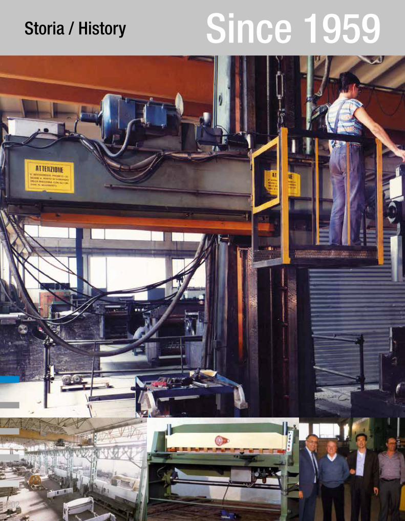
Storia / History Since 1959
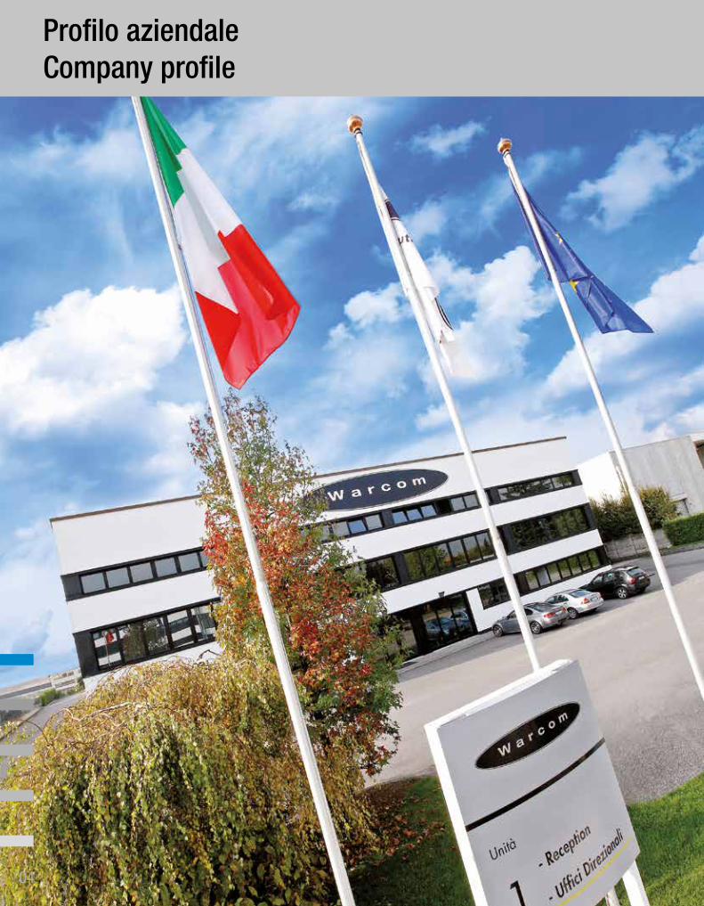
Profilo aziendaleCompany profile
Nel 1959 Giovanni Robazza, non ancora ventenne, realizzò la prima cesoia meccanica in ghisa con il marchio “ROMEA”. Trasformò la sua bottega di fabbro in una realtà artigianale per produrre macchine per la lavorazione della lamiera. Nel 1979 Walter Roberto Robazza, figlio di Giovanni, costituì la Warcom Spa industrializzando la produzione di presse piegatrici e cesoie oleodinamiche a controllo numerico. Attualmente Warcom è gestita sapientemente dalla terza generazione della famiglia Robazza, dai fratelli Alberto e Paolo. L’azienda si sviluppa su una superficie di circa 5.000 m2 coperti; conta un organico di 40 dipendenti, 2 filiali commerciali estere e una rete di vendita in tutto il mondo.
VISIONOggi Warcom è un’azienda familiare e tecnologicamente all’avanguardia con profonde radici storiche. L’azienda si colloca tra i leader italiani nella produzione di presse piegatrici, cesoie, macchine a taglio al plasma e taglio laser. Dopo una fase di ristrutturazione interna, con il nuovo assetto aziendale, la Warcom è proiettata a nuove sfide nel mercato internazionale sempre con dedizione e attenzione alle esigenze e soddisfazioni dei clienti.
MISSIONWarcom si impegna costantemente a fornire le migliori soluzioni possibili agli operatori nel settore della carpenteria industriale specializzata. Warcom considera la chiave del proprio successo la fidelizzazione del cliente e l’etica professionale, supportate dalla competenza tecnica e dalla passione dedicata al proprio lavoro. Attraverso l’alta qualità tecnica del prodotto e la cura del design Warcom rilancia il “MADE IN ITALY” sul mercato internazionale della lavorazione lamiera.
In 1959 Giovanni Robazza built the first mechanical shear in cast iron by “ROMEA” brand. He has changed his small workshop in an artisan job, starting the production of machines tools for sheet metal working. In 1979 Walter Roberto Robazza, Giovanni’s son, founded Warcom Spa, industrializing the production of hydraulic press brakes and shears with CNC numeric control. Now Warcom is managed by the third generation of Robazza family by Alberto and Paolo brothers. Warcom grows over an area of about 5000 m2 and has a staff of 40 employees, 2 foreign branches offices and a worldwide network sale.
VISIONToday Warcom is high technology company, at family style with old history. Warcom is one of the Italian leader manufacturers of press brakes, shears, plasma cutting machines and fiber laser machines. After a restructuring, the new company’s arrangement is focused on undertake new challenges on the international market, always with dedication and attention to the customer needs and satisfaction.
MISSIONWarcom focuses his efforts to provide the best solutions to the specialized metalworking customers. Warcom believes that the key of success is the customer loyalty and professional ethic, together with technical expertise and work passion. With the high quality products and the attention to the product details and design, Warcom reintroduces the “MADE IN ITALY” on the international market of sheet metal working.
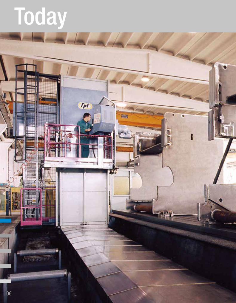
Today
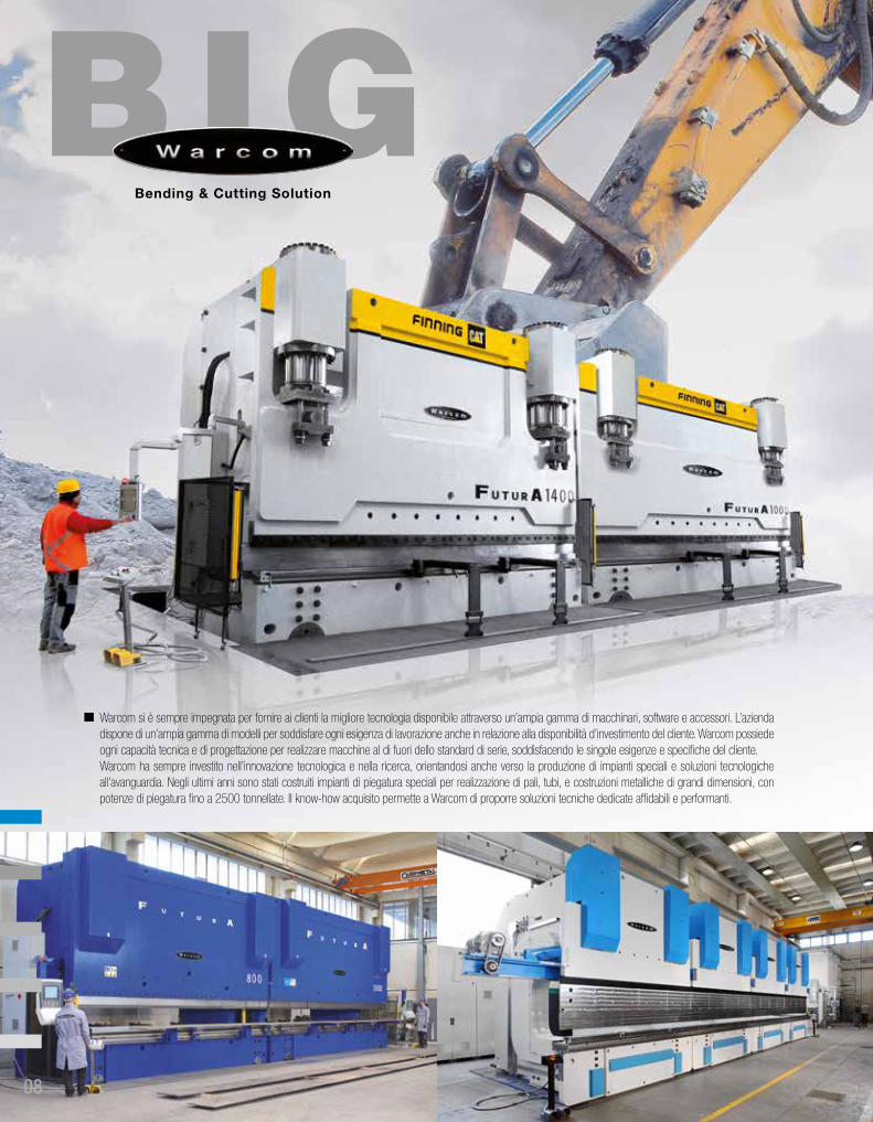
Warcom si è sempre impegnata per fornire ai clienti la migliore tecnologia disponibile attraverso un’ampia gamma di macchinari, software e accessori. L’azienda dispone di un’ampia gamma di modelli per soddisfare ogni esigenza di lavorazione anche in relazione alla disponibilità d’investimento del cliente. Warcom possiede ogni capacità tecnica e di progettazione per realizzare macchine al di fuori dello standard di serie, soddisfacendo le singole esigenze e specifiche del cliente.Warcom ha sempre investito nell’innovazione tecnologica e nella ricerca, orientandosi anche verso la produzione di impianti speciali e soluzioni tecnologiche all’avanguardia. Negli ultimi anni sono stati costruiti impianti di piegatura speciali per realizzazione di pali, tubi, e costruzioni metalliche di grandi dimensioni, con potenze di piegatura fino a 2500 tonnellate. Il know-how acquisito permette a Warcom di proporre soluzioni tecniche dedicate affidabili e performanti.
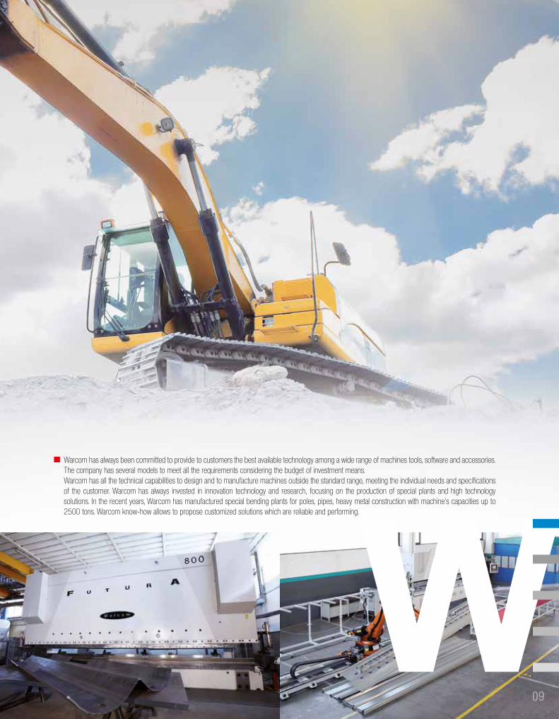
Warcom has always been committed to provide to customers the best available technology among a wide range of machines tools, software and accessories. The company has several models to meet all the requirements considering the budget of investment means. Warcom has all the technical capabilities to design and to manufacture machines outside the standard range, meeting the individual needs and specifications of the customer. Warcom has always invested in innovation technology and research, focusing on the production of special plants and high technology solutions. In the recent years, Warcom has manufactured special bending plants for poles, pipes, heavy metal construction with machine’s capacities up to 2500 tons. Warcom know-how allows to propose customized solutions which are reliable and performing.
Presse PiegatriciPress Brakes
Nella lavorazione della lamiera, una delle condizioni più critiche è ottenere le tolleranze geometriche richieste per il prodotto finito. Il risultato di piegatura ottimale è definito da due fattori principali:
• Valore dell’angolo di piega nelle tolleranze richieste.• Angolo di piegatura costante su tutta la lunghezza del pezzo piegato.
Per ottenere un risultato ottimale è indispensabile approfondire alcuni concetti.
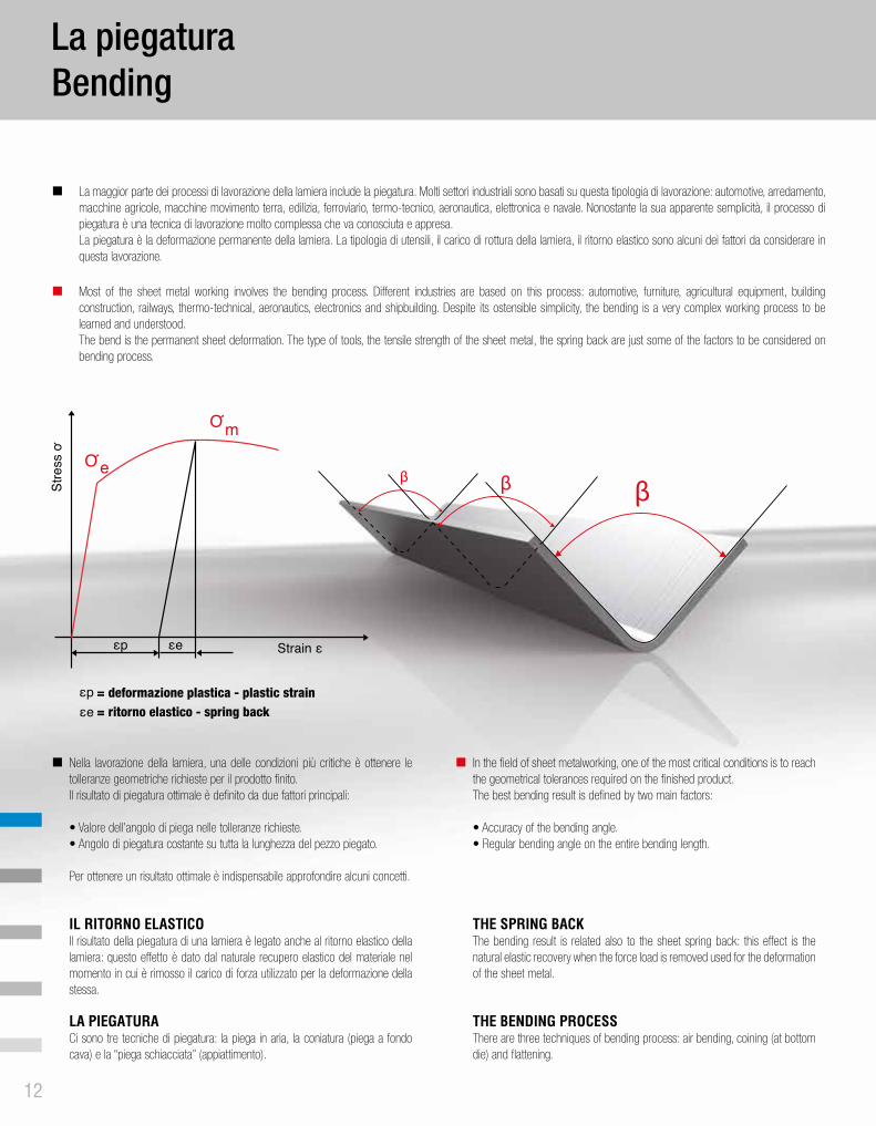
IL RITORNO ELASTICOIl risultato della piegatura di una lamiera è legato anche al ritorno elastico della lamiera: questo effetto è dato dal naturale recupero elastico del materiale nel momento in cui è rimosso il carico di forza utilizzato per la deformazione della stessa.
LA PIEGATURACi sono tre tecniche di piegatura: la piega in aria, la coniatura (piega a fondo cava) e la “piega schiacciata” (appiattimento).
In the field of sheet metalworking, one of the most critical conditions is to reach the geometrical tolerances required on the finished product. The best bending result is defined by two main factors:
• Accuracy of the bending angle.• Regular bending angle on the entire bending length.
THE SPRING BACKThe bending result is related also to the sheet spring back: this effect is the natural elastic recovery when the force load is removed used for the deformation of the sheet metal.
THE BENDING PROCESSThere are three techniques of bending process: air bending, coining (at bottom die) and flattening.
La piegaturaBending
e
m
= deformazione plastica - plastic strain= ritorno elastico - spring back
La maggior parte dei processi di lavorazione della lamiera include la piegatura. Molti settori industriali sono basati su questa tipologia di lavorazione: automotive, arredamento, macchine agricole, macchine movimento terra, edilizia, ferroviario, termo-tecnico, aeronautica, elettronica e navale. Nonostante la sua apparente semplicità, il processo di piegatura è una tecnica di lavorazione molto complessa che va conosciuta e appresa. La piegatura è la deformazione permanente della lamiera. La tipologia di utensili, il carico di rottura della lamiera, il ritorno elastico sono alcuni dei fattori da considerare in questa lavorazione.
Most of the sheet metal working involves the bending process. Different industries are based on this process: automotive, furniture, agricultural equipment, building construction, railways, thermo-technical, aeronautics, electronics and shipbuilding. Despite its ostensible simplicity, the bending is a very complex working process to be learned and understood. The bend is the permanent sheet deformation. The type of tools, the tensile strength of the sheet metal, the spring back are just some of the factors to be considered on bending process.
Tipologia di piegaturaBending tecnique
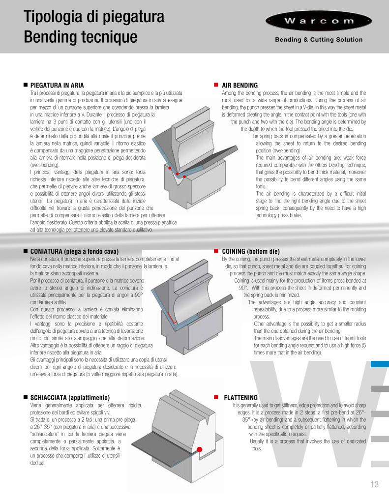
PIEGATURA IN ARIATra i processi di piegatura, la piegatura in aria e la più semplice e la più utilizzata in una vasta gamma di produzioni. Il processo di piegatura in aria si esegue per mezzo di un punzone superiore che scendendo pressa la lamiera in una matrice inferiore a V. Durante il processo di piegatura la lamiera ha 3 punti di contatto con gli utensili (uno con il vertice del punzone e due con la matrice). L’angolo di piega è determinato dalla profondità alla quale il punzone preme la lamiera nella matrice, quindi variabile. Il ritorno elastico è compensato da una maggiore penetrazione permettendo alla lamiera di ritornare nella posizione di piega desiderata (over-bending). I principali vantaggi della piegatura in aria sono: forza richiesta inferiore rispetto alle altre tecniche di piegatura, che permette di piegare anche lamiere di grosso spessore e possibilità di ottenere angoli diversi utilizzando gli stessi utensili. La piegatura in aria è caratterizzata dalla iniziale difficoltà nel trovare la giusta penetrazione del punzone che permette di compensare il ritorno elastico della lamiera per ottenere l’angolo desiderato. Questo criterio obbliga la scelta di una pressa piegatrice ad alta tecnologia per ottenere uno elevato standard qualitativo.
CONIATURA (piega a fondo cava)Nella coniatura, il punzone superiore pressa la lamiera completamente fino al fondo cava nella matrice inferiore, in modo che il punzone, la lamiera, e la matrice siano accoppiati insieme. Per il processo di coniatura, il punzone e la matrice devono avere lo stesso angolo di inclinazione. La coniatura è utilizzata principalmente per la piegatura di angoli a 90° con lamiera sottile.Con questo processo la lamiera è coniata eliminando l’effetto del ritorno elastico del materiale.I vantaggi sono la precisione e ripetibilità costante dell’angolo di piegatura dovuto a una tecnica di lavorazione molto più simile allo stampaggio che alla deformazione. Altro vantaggio è la possibilità di ottenere un raggio di piegatura inferiore rispetto alla piegatura in aria. Gli svantaggi principali sono la necessità di utilizzare una copia di utensili diversi per ogni angolo di piegatura desiderato e la necessità di utilizzare un’elevata forza di piegatura (5 volte maggiore rispetto alla piegatura in aria).
SCHIACCIATA (appiattimento)Viene generalmente applicata per ottenere rigidità, protezione dei bordi ed evitare spigoli vivi. Si tratta di un processo a 2 fasi: una prima pre-piega a 26°-35° (con piegatura in aria) e una successiva “schiacciatura” in cui la lamiera piegata viene completamente o parzialmente appiattita, a seconda della forza applicata. Solitamente è un processo che comporta l’ utilizzo di utensili dedicati.
AIR BENDINGAmong the bending process, the air bending is the most simple and the most used for a wide range of productions. During the process of air bending, the punch presses the sheet in a V-die. In this way the sheet metal is deformed creating the angle in the contact point with the tools (one with
the punch and two with the die). The bending angle is determined by the depth to which the tool pressed the sheet into the die.
The spring back is compensated by a greater penetration allowing the sheet to return to the desired bending position (over-bending). The main advantages of air bending are: weak force required comparable with the others bending technique, that gives the possibility to bend thick material, moreover the possibility to bend different angles using the same tools. The air bending is characterized by a difficult initial stage to find the right bending angle due to the sheet spring back, consequently by the need to have a high technology press brake.
COINING (bottom die)By the coining, the punch presses the sheet metal completely in the lower
die, so that punch, sheet metal and die are coupled together. For coining process the punch and die must match exactly the same angle shape.
Coining is used mainly for the production of items press bended at 90°. With this process the sheet is deformed permanently and
the spring back is minimized. The advantages are high angle accuracy and constant
repeatability, due to a process more similar to the molding process. Other advantage is the possibility to get a smaller radius than the one obtained during the air bending. The main disadvantages are the need to use different tools for each bending angle request and to use a high force (5 times more that in the air bending).
FLATTENINGIt is generally used to get stiffness, edge protection and to avoid sharp
edges. It is a process made in 2 steps: a first pre-bend at 26°-35° (by air bending) and a subsequent flattening in which the
bending sheet is completely or partially flattened, according with the specification request. Usually it is a process that involves the use of dedicated tools.
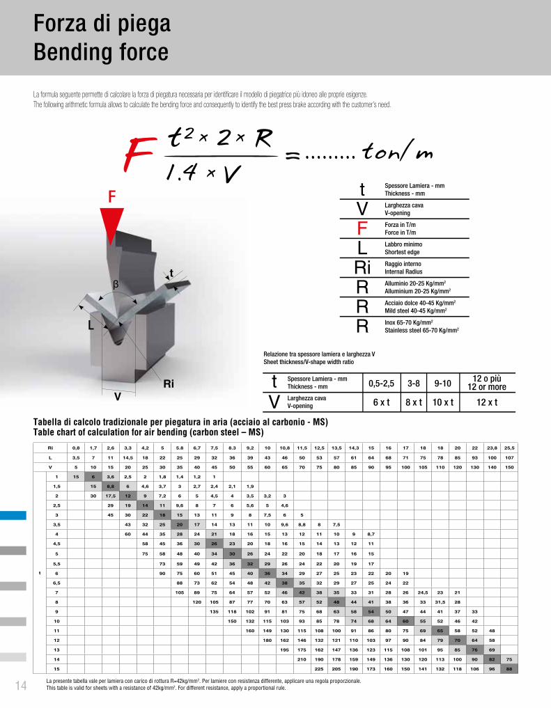
La formula seguente permette di calcolare la forza di piegatura necessaria per identificare il modello di piegatrice più idoneo alle proprie esigenze.The following arithmetic formula allows to calculate the bending force and consequently to identify the best press brake according with the customer’s need.
tVFLRiRRR
Spessore Lamiera - mmThickness - mm
Larghezza cavaV-opening
Forza in T/mForce in T/m
Labbro minimoShortest edge
Raggio internoInternal Radius
Alluminio 20-25 Kg/mm2
Alluminium 20-25 Kg/mm2
Acciaio dolce 40-45 Kg/mm2
Mild steel 40-45 Kg/mm2
Inox 65-70 Kg/mm2
Stainless steel 65-70 Kg/mm2
tV
Spessore Lamiera - mmThickness - mm 0,5-2,5 3-8 9-10 12 o più
12 or more
6 x t 8 x t 10 x t 12 x tLarghezza cavaV-opening
Relazione tra spessore lamiera e larghezza VSheet thickness/V-shape width ratio
Ri 0,8 1,7 2,6 3,3 4,2 5 5.8 6,7 7,5 8.3 9,2 10 10,8 11,5 12,5 13,5 14,3 15 16 17 18 18 20 22 23,8 25,5
L 3,5 7 11 14,5 18 22 25 29 32 36 39 43 46 50 53 57 61 64 68 71 75 78 85 93 100 107
V 5 10 15 20 25 30 35 40 45 50 55 60 65 70 75 80 85 90 95 100 105 110 120 130 140 150
t
1 15 6 3,6 2,5 2 1,8 1,4 1,2 1
1,5 15 8,8 6 4,6 3,7 3 2,7 2,4 2,1 1,9
2 30 17,5 12 9 7,2 6 5 4,5 4 3,5 3,2 3
2,5 29 19 14 11 9,6 8 7 6 5,6 5 4,6
3 45 30 22 18 15 13 11 9 8 7,5 6 5
3,5 43 32 25 20 17 14 13 11 10 9,6 8,8 8 7,5
4 60 44 35 28 24 21 18 16 15 13 12 11 10 9 8,7
4,5 58 45 36 30 26 23 20 18 16 15 14 13 12 11
5 75 58 48 40 34 30 26 24 22 20 18 17 16 15
5,5 73 59 49 42 36 32 29 26 24 22 20 19 17
6 90 75 60 51 45 40 36 34 29 27 25 23 22 20 19
6,5 88 73 62 54 48 42 38 35 32 29 27 25 24 22
7 105 89 75 64 57 52 46 42 38 35 33 31 28 26 24,5 23 21
8 120 105 87 77 70 63 57 52 48 44 41 38 36 33 31,5 28
9 135 118 102 91 81 75 68 63 58 54 50 47 44 41 37 33
10 150 132 115 103 93 85 78 74 68 64 60 55 52 46 42
11 160 149 130 115 108 100 91 86 80 75 69 65 58 52 48
12 180 162 146 132 121 110 103 97 90 84 79 70 64 58
13 195 175 162 147 136 123 115 108 101 95 85 76 69
14 210 190 178 159 149 136 130 120 113 100 90 82 75
15 225 205 190 173 160 150 141 132 118 106 96 88
La presente tabella vale per lamiera con carico di rottura R=42kg/mm2. Per lamiere con resistenza differente, applicare una regola proporzionale.This table is valid for sheets with a resistance of 42kg/mm2. For different resistance, apply a proportional rule.
Tabella di calcolo tradizionale per piegatura in aria (acciaio al carbonio - MS)Table chart of calculation for air bending (carbon steel – MS)
VRi
t
ACCIAIO AD ALTA RESISTENZA (HSS)
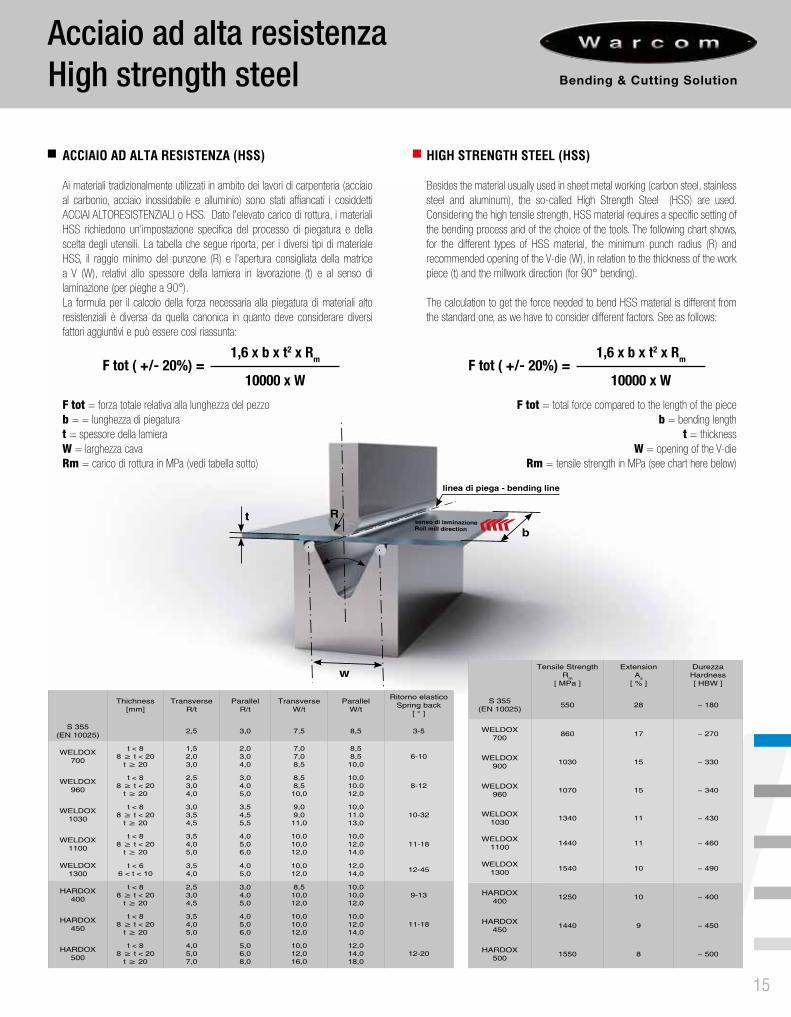
Ai materiali tradizionalmente utilizzati in ambito dei lavori di carpenteria (acciaio al carbonio, acciaio inossidabile e alluminio) sono stati affiancati i cosiddetti ACCIAI ALTORESISTENZIALI o HSS. Dato l’elevato carico di rottura, i materiali HSS richiedono un’impostazione specifica del processo di piegatura e della scelta degli utensili. La tabella che segue riporta, per i diversi tipi di materiale HSS, il raggio minimo del punzone (R) e l’apertura consigliata della matrice a V (W), relativi allo spessore della lamiera in lavorazione (t) e al senso di laminazione (per pieghe a 90°).La formula per il calcolo della forza necessaria alla piegatura di materiali alto resistenziali è diversa da quella canonica in quanto deve considerare diversi fattori aggiuntivi e può essere cosi riassunta:
F tot = forza totale relativa alla lunghezza del pezzob = = lunghezza di piegaturat = spessore della lamieraW = larghezza cavaRm = carico di rottura in MPa (vedi tabella sotto)
HIGH STRENGTH STEEL (HSS)
Besides the material usually used in sheet metal working (carbon steel, stainless steel and aluminum), the so-called High Strength Steel (HSS) are used. Considering the high tensile strength, HSS material requires a specific setting of the bending process and of the choice of the tools. The following chart shows, for the different types of HSS material, the minimum punch radius (R) and recommended opening of the V-die (W), in relation to the thickness of the work piece (t) and the millwork direction (for 90° bending).
The calculation to get the force needed to bend HSS material is different from the standard one, as we have to consider different factors. See as follows:
F tot = total force compared to the length of the pieceb = bending length
t = thickness W = opening of the V-die
Rm = tensile strength in MPa (see chart here below)
Acciaio ad alta resistenzaHigh strength steel
Thichness[mm]
TransverseR/t
ParallelR/t
TransverseW/t
ParallelW/t
Ritorno elasticoSpring back
[ ° ]
S 355 (EN 10025) 2,5 3,0 7,5 8,5 3-5
WELDOX 700
t < 88 ≥ t < 20
t ≥ 20
1,52,03,0
2,03,04,0
7,07,08,5
8,58,5
10,06-10
WELDOX 960
t < 88 ≥ t < 20
t ≥ 20
2,53,04,0
3,04,05,0
8,58,5
10,0
10,010.012,0
8-12
WELDOX 1030
t < 88 ≥ t < 20
t ≥ 20
3,03,54,5
3,54,55,5
9,09,0
11,0
10,011.013,0
10-32
WELDOX 1100
t < 88 ≥ t < 20
t ≥ 20
3,54,05,0
4,05,06,0
10.010,012,0
10,012,014,0
11-18
WELDOX 1300
t < 66 < t < 10
3,54,0
4,05,0
10,012,0
12,014,0 12-45
HARDOX 400
t < 88 ≥ t < 20
t ≥ 20
2,53,04,5
3,04,05,0
8,510,012,0
10,010,012,0
9-13
HARDOX 450
t < 88 ≥ t < 20
t ≥ 20
3,54,05,0
4,05,06,0
10,010,012,0
10,012,014,0
11-18
HARDOX 500
t < 88 ≥ t < 20
t ≥ 20
4,05,07,0
5,06,08,0
10,012,016,0
12,014,018,0
12-20
Tensile Strength Rm
[ MPa ]
Extension As
[ % ]
DurezzaHardness[ HBW ]
S 355 (EN 10025) 550 28 ~ 180
WELDOX 700 860 17 ~ 270
WELDOX 900 1030 15 ~ 330
WELDOX 960 1070 15 ~ 340
WELDOX 1030 1340 11 ~ 430
WELDOX 1100 1440 11 ~ 460
WELDOX 1300 1540 10 ~ 490
HARDOX 400 1250 10 ~ 400
HARDOX 450 1440 9 ~ 450
HARDOX 500 1550 8 ~ 500
CARATTERISTICHE REGISTRO M1 BACKGAUGE FEATURES
Corsa asse X 600 mm X axis stroke
Velocità asse X 500 mm/sec X axis speed
Risoluzione Meccanica +/- 0,05 mm Mechanical Resolution
Corsa asse R 150 mm R axis stroke
Velocità asse R 200 mm/sec R axis speed
Risoluzione Meccanica +/- 0,05 mm Mechanical Resolution
Velocità asse Z 1100 mm/sec Z axis speed
Risoluzione Meccanica +/- 0,1 mm Mechanical Resolution
Corsa asse X5-X6 +/- 130 mm X5-X6 axis stroke
Velocità asse X5-X6 150 mm/sec X5-X6 axis speed
Risoluzione Meccanica +/- 0,1 mm Mechanical Resolution
Angolo d’inclinazione massimo asse X6 60° X6 maximum tilt angle
Angolo d’inclinazione massimo assi X5-X6 75° X5-X6 maximum tilt angle
DCSDynamic Crowning System
90°
90°>90° 90°90° 90° <90°90°90°
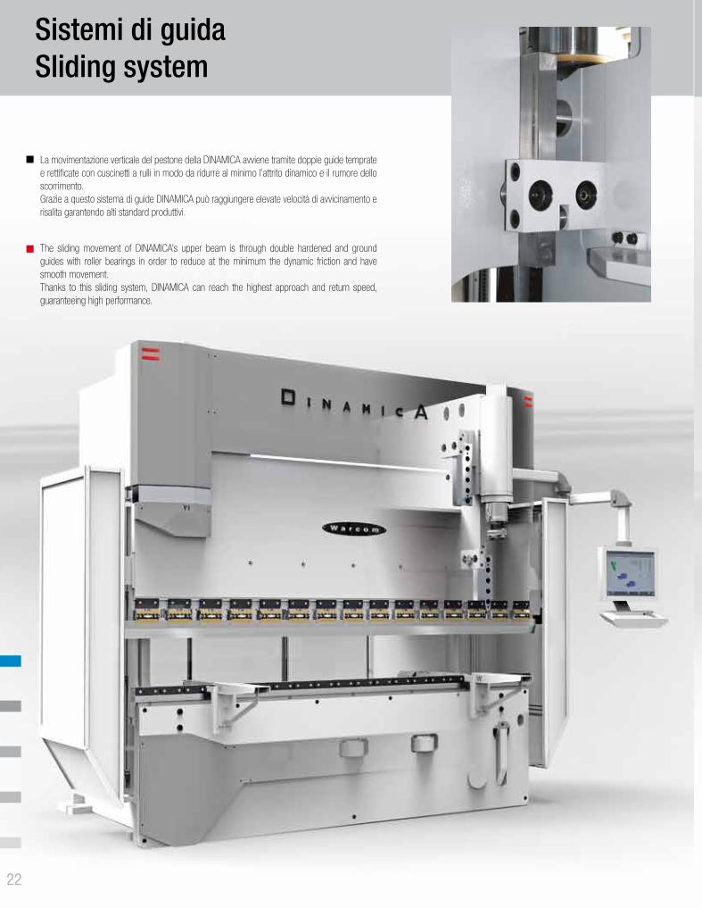
La movimentazione verticale del pestone della DINAMICA avviene tramite doppie guide temprate e rettificate con cuscinetti a rulli in modo da ridurre al minimo l’attrito dinamico e il rumore dello scorrimento. Grazie a questo sistema di guide DINAMICA può raggiungere elevate velocità di avvicinamento e risalita garantendo alti standard produttivi.
The sliding movement of DINAMICA’s upper beam is through double hardened and ground guides with roller bearings in order to reduce at the minimum the dynamic friction and have smooth movement.Thanks to this sliding system, DINAMICA can reach the highest approach and return speed, guaranteeing high performance.
21 22
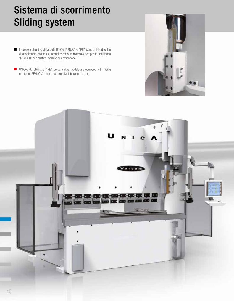
Sistemi di guidaSliding system
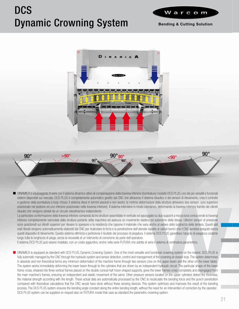
DINAMICA è equipaggiata di serie con il sistema dinamico attivo di compensazione della traversa inferiore (bombatura) modello DCS PLUS, uno dei più versatili e funzionali sistemi disponibili sul mercato. DCS PLUS è completamente automatico gestito dal CNC che attraverso il sistema idraulico e dei sensori di rilevamento, crea il controllo e gestione della bombatura a loop-chiuso. Il sistema rileva in termini assoluti e non teorici, le minime deformazioni della struttura attraverso due sensori (uno superiore posizionato nel pestone ed uno inferiore posizionato nella traversa inferiore). Il sistema interviene in modo istantaneo, deformando la traversa inferiore tramite dei cilindri idraulici che vengono pilotati da un circuito oleodinamico indipendente. La particolare conformazione della traversa inferiore composta da tre strutture assemblate in verticale ed appoggiate su due supporti a mezza luna conica rende la traversa inferiore completamente svincolata dalla struttura portante della macchina ed assicura un movimento elastico ed autonomo della stessa. Ulteriori sensori di pressione sono posizionati sui cilindri superiori per rilevare lo spessore e la resistenza che oppone il materiale che varia anche al variare della lunghezza della lamiera. Questi dati reali rilevati vengono automaticamente elaborati dal CNC per ricalcolare la forza e la penetrazione dell’utensile rispetto ai calcoli teorici che il CNC avrebbe eseguito senza questi dispositivi di rilevamento. Questo sistema ottimizza e perfeziona il risultato del processo di piegatura. Il sistema DCS PLUS garantisce l’angolo di piegatura costante lungo tutta la lunghezza di piega, senza la necessità di un intervento di correzione da parte dell’operatore. Il sistema DCS PLUS può essere installato, con un costo aggiuntivo, anche nella serie FUTURA che adotta di serie il sistema di centinatura parametrico.
DINAMICA is equipped as standard with DCS PLUS, Dynamic Crowning System. One of the most versatile and functional crowning system on the market. DCS PLUS is fully automatic managed by the CNC through the hydraulic system and sensor detection, control and management of the crowning at closed-loop. The system determines in absolute and non theoretical terms any minimum deformation of the machine frame through two sensors (one on the upper beam and the other on the lower table).The system works immediately deforming the lower beam through to the cylinders that are driven by an independent hydraulic circuit. The particular shape of the lower frame-cross, sheared into three vertical frames placed on the double conical half moon-shaped supports, gives the lower frames-cross completely and disengaged from the main machine’s frames, ensuring an independent and elastic movement of the same. Other pressure sensors located on the upper cylinders detect the thickness, the material strength according with the length. These actual data are automatically processed by the CNC to recalculate the bending force and the punch penetration compared with theoretical calculations that the CNC would have done without these sensing devices. This system optimizes and improves the result of the bending process. The DCS PLUS system ensures the bending angle constant along the entire bending length, without the need for an intervention of correction by the operator. DCS PLUS system can be supplied on request also on FUTURA model that uses as standard the parametric crowning system.
Flessione della strutturaDeflection of the structure
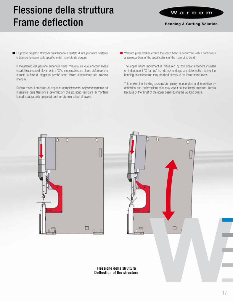
Le presse piegatrici Warcom garantiscono il risultato di una piegatura costante indipendentemente dalle specifiche del materiale da piegare.
Il movimento del pestone superiore viene misurata da due encoder lineari installati su ancore di rilevamento a “C” che non subiscono alcuna deformazione durante la fase di piegatura perché sono fissate direttamente alla traversa inferiore.
Questo rende il processo di piegatura completamente indipendentemente ed insensibile dalle flessioni e deformazioni che possono verificarsi ai montanti laterali a causa della spinta del pestone durante la fase di lavoro.
Warcom press brakes ensure that each bend is performed with a continuous angle regardless of the specifications of the material to bend.
The upper beam movement is measured by two linear encoders installed on independent “C frames” that do not undergo any deformation during the bending phase because they are fixed directly to the lower frame-cross.
This makes the bending process completely independent and insensitive by deflection and deformations that may occur to the lateral machine frames because of the thrust of the upper beam during the working phase.
Flessione della strutturaFrame deflection
17
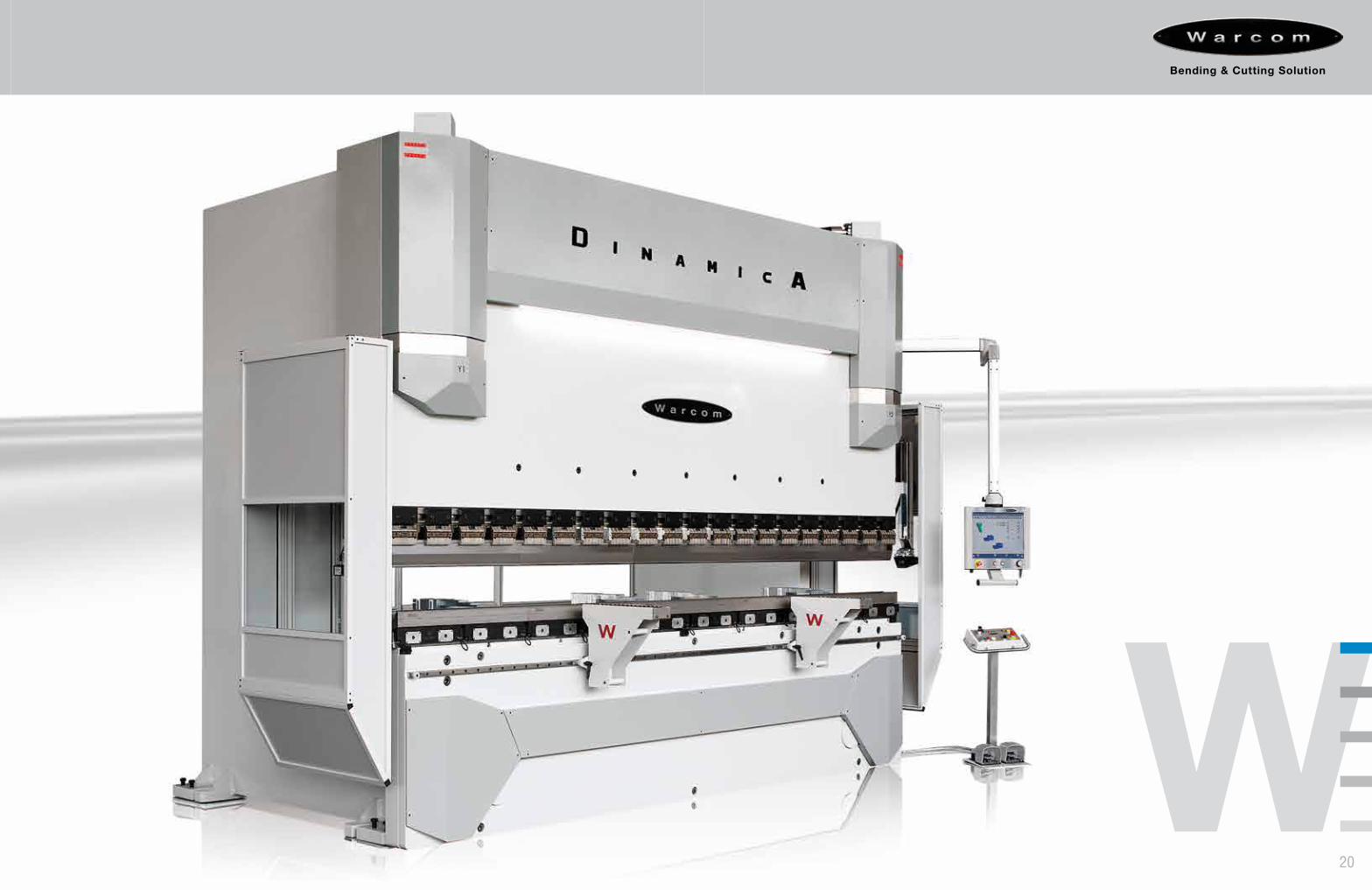
La pressa piegatrice sincronizzata DINAMICA rappresenta il più alto livello di tecnologia della gamma Warcom, con elevate performance di precisione e produttività.DINAMICA è dotata di un CNC con comando touch screen e ampio schermo da 19”. È dotata di: aperture e corse maggiorate, sistema di comunicazione digitale CAN/BUS, scambiatore di calore, pompa silenziata di serie.DINAMICA è caratterizzata da un design elegante e curato in ogni minimo dettaglio. DINAMICA è un prodotto realizzato per la clientela più esigente che necessità di una piegatrice ergonomica, funzionale, precisa e veloce. È la macchina ideale per contoterzisti, centri servizi, carpenterie industriali e per tutti coloro che necessitano alta produttività e qualità.
The synchronized press brake model DINAMICA meets the highest technology level of Warcom’s product range, with high performance of precision and productivity. DINAMICA is equipped with a full touch screen 19” CNC.It has an increased distance between table and upper beam and Y axis stroke, a CAN/BUS digital system, heat exchanger, soundproof hydraulic pump on standard equipment.DINAMICA is characterized by an elegant design with attention to every details.DINAMICA is the machine designed for the most demanding customers who need an ergonomic, functional, accurate and fast press brake. It is the best machine for job-shop, service centers and sheet metal working factories and for all who are looking for high quality and productivity.
2018
DCSDynamic Crowning System
90°
90°>90° 90°90° 90° <90°90°90°
La movimentazione verticale del pestone della DINAMICA avviene tramite doppie guide temprate e rettificate con cuscinetti a rulli in modo da ridurre al minimo l’attrito dinamico e il rumore dello scorrimento. Grazie a questo sistema di guide DINAMICA può raggiungere elevate velocità di avvicinamento e risalita garantendo alti standard produttivi.
The sliding movement of DINAMICA’s upper beam is through double hardened and ground guides with roller bearings in order to reduce at the minimum the dynamic friction and have smooth movement.Thanks to this sliding system, DINAMICA can reach the highest approach and return speed, guaranteeing high performance.
21 22
Sistemi di guidaSliding system
DINAMICA è equipaggiata di serie con il sistema dinamico attivo di compensazione della traversa inferiore (bombatura) modello DCS PLUS, uno dei più versatili e funzionali sistemi disponibili sul mercato. DCS PLUS è completamente automatico gestito dal CNC che attraverso il sistema idraulico e dei sensori di rilevamento, crea il controllo e gestione della bombatura a loop-chiuso. Il sistema rileva in termini assoluti e non teorici, le minime deformazioni della struttura attraverso due sensori (uno superiore posizionato nel pestone ed uno inferiore posizionato nella traversa inferiore). Il sistema interviene in modo istantaneo, deformando la traversa inferiore tramite dei cilindri idraulici che vengono pilotati da un circuito oleodinamico indipendente. La particolare conformazione della traversa inferiore composta da tre strutture assemblate in verticale ed appoggiate su due supporti a mezza luna conica rende la traversa inferiore completamente svincolata dalla struttura portante della macchina ed assicura un movimento elastico ed autonomo della stessa. Ulteriori sensori di pressione sono posizionati sui cilindri superiori per rilevare lo spessore e la resistenza che oppone il materiale che varia anche al variare della lunghezza della lamiera. Questi dati reali rilevati vengono automaticamente elaborati dal CNC per ricalcolare la forza e la penetrazione dell’utensile rispetto ai calcoli teorici che il CNC avrebbe eseguito senza questi dispositivi di rilevamento. Questo sistema ottimizza e perfeziona il risultato del processo di piegatura. Il sistema DCS PLUS garantisce l’angolo di piegatura costante lungo tutta la lunghezza di piega, senza la necessità di un intervento di correzione da parte dell’operatore. Il sistema DCS PLUS può essere installato, con un costo aggiuntivo, anche nella serie FUTURA che adotta di serie il sistema di centinatura parametrico.
DINAMICA is equipped as standard with DCS PLUS, Dynamic Crowning System. One of the most versatile and functional crowning system on the market. DCS PLUS is fully automatic managed by the CNC through the hydraulic system and sensor detection, control and management of the crowning at closed-loop. The system determines in absolute and non theoretical terms any minimum deformation of the machine frame through two sensors (one on the upper beam and the other on the lower table).The system works immediately deforming the lower beam through to the cylinders that are driven by an independent hydraulic circuit. The particular shape of the lower frame-cross, sheared into three vertical frames placed on the double conical half moon-shaped supports, gives the lower frames-cross completely and disengaged from the main machine’s frames, ensuring an independent and elastic movement of the same. Other pressure sensors located on the upper cylinders detect the thickness, the material strength according with the length. These actual data are automatically processed by the CNC to recalculate the bending force and the punch penetration compared with theoretical calculations that the CNC would have done without these sensing devices. This system optimizes and improves the result of the bending process. The DCS PLUS system ensures the bending angle constant along the entire bending length, without the need for an intervention of correction by the operator. DCS PLUS system can be supplied on request also on FUTURA model that uses as standard the parametric crowning system.
Flessione della strutturaDeflection of the structure
Le presse piegatrici Warcom garantiscono il risultato di una piegatura costante indipendentemente dalle specifiche del materiale da piegare.
Il movimento del pestone superiore viene misurata da due encoder lineari installati su ancore di rilevamento a “C” che non subiscono alcuna deformazione durante la fase di piegatura perché sono fissate direttamente alla traversa inferiore.
Questo rende il processo di piegatura completamente indipendentemente ed insensibile dalle flessioni e deformazioni che possono verificarsi ai montanti laterali a causa della spinta del pestone durante la fase di lavoro.
Warcom press brakes ensure that each bend is performed with a continuous angle regardless of the specifications of the material to bend.
The upper beam movement is measured by two linear encoders installed on independent “C frames” that do not undergo any deformation during the bending phase because they are fixed directly to the lower frame-cross.
This makes the bending process completely independent and insensitive by deflection and deformations that may occur to the lateral machine frames because of the thrust of the upper beam during the working phase.
Flessione della strutturaFrame deflection
17
R
Z1Z2
X6X5
27 28
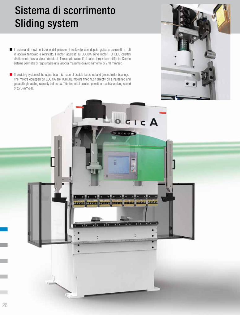
Il sistema di movimentazione del pestone è realizzato con doppia guida a cuscinetti a rulli in acciaio temprato e rettificato. I motori applicati su LOGICA sono motori TORQUE calettati direttamente su una vite a ricircolo di sfere ad alta capacità di carico temprata e rettificata. Questo sistema permette di raggiungere una velocità massima di avvicinamento di 270 mm/sec.
The sliding system of the upper beam is made of double hardened and ground roller bearings.The motors equipped on LOGICA are TORQUE motors fitted flush directly on a hardened and ground high loading capacity ball screw. This technical solution permit to reach a working speed of 270 mm/sec.
23
Registro posteriore Backgauge
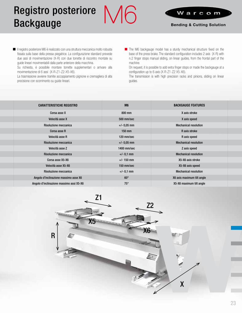
Il registro posteriore M6 è realizzato con una struttura meccanica molto robusta fissata sulla base della pressa piegatrice. La configurazione standard prevede due assi di movimentazione (X-R) con due torrette di riscontro montate su guide lineari movimentabili dalla parte anteriore della macchina.Su richiesta, è possibile montare torrette supplementari o arrivare alla movimentazione di 6 assi (X-R-Z1-Z2-X5-X6).La trasmissione avviene tramite accoppiamento pignone e cremagliera di alta precisione con scorrimento su guide lineari.
The M6 backgauge model has a sturdy mechanical structure fixed on the base of the press brake. The standard configuration includes 2 axis (X-R) with n.2 finger stops manual sliding, on linear guides, from the frontal part of the machine. On request, it is possible to add extra finger stops or made the backgauge at a configuration up to 6 axis (X-R-Z1-Z2 X5-X6). The transmission is with high precision racks and pinions, sliding on linear guides.
CARATTERISTICHE REGISTRO M6 BACKGAUGE FEATURES
Corsa asse X 800 mm X axis stroke
Velocità asse X 500 mm/sec X axis speed
Risoluzione meccanica +/- 0,05 mm Mechanical resolution
Corsa asse R 150 mm R axis stroke
Velocità asse R 120 mm/sec R axis speed
Risoluzione meccanica +/- 0,05 mm Mechanical resolution
Velocità asse Z 1400 mm/sec Z axis speed
Risoluzione meccanica +/- 0,1 mm Mechanical resolution
Corsa asse X5-X6 +/- 150 mm X5-X6 axis stroke
Velocità asse X5-X6 150 mm/sec X5-X6 axis speed
Risoluzione meccanica +/- 0,1 mm Mechanical resolution
Angolo d’inclinazione massimo asse X6 60° X6 axis maximum tilt angle
Angolo d’inclinazione massimo assi X5-X6 75° X5-X6 maximum tilt angle
X
Sistema di scorrimentoSliding system M6
2624
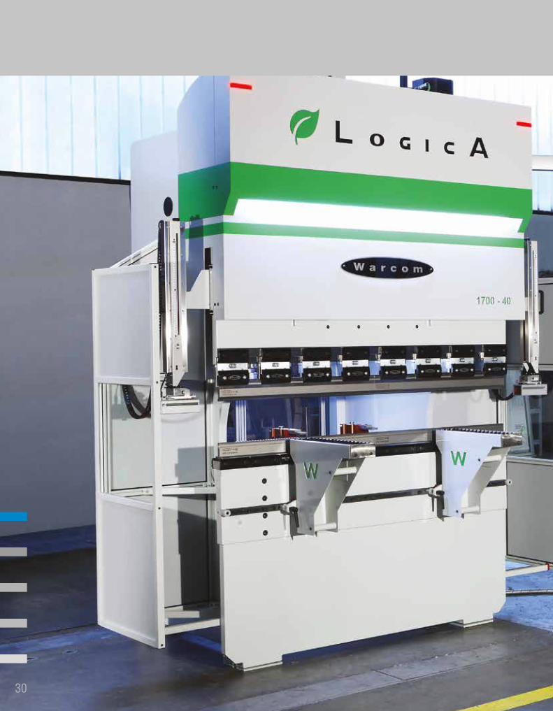
La serie LOGICA rappresenta un’ottima combinazione di design moderno e raffinato, innovazione ed elevata tecnologia. Il rivoluzionario sistema di trasmissione diretta tra motore e pestone, senza ulteriori organi di rinvio meccanico, rende il sistema estremamente affidabile, preciso, efficiente e silenzioso, con una velocità superiore a qualsiasi altro cinematismo. LOGICA viene fornita con registri altamente performanti, movimentati da pignoni e cremagliere su guide lineari di precisione. È il prodotto ideale per l’esecuzione di piccoli presso piegati in serie con altissima produttività e ripetibilità.
LOGICA represents a great combination between modern and elegant design, innovation and high level technology. The revolutionary direct drive system, between servo motor and upper beam, without any mechanical drive organs, makes the system extremely reliable, accurate, efficient and quiet, with a speed higher than any other kinematic system available. LOGICA is supplied with high performance backgauge, moved by racks and pinions on high accuracy linear guides. This is the perfect machine for small bends in series with high productivity and repeatability.
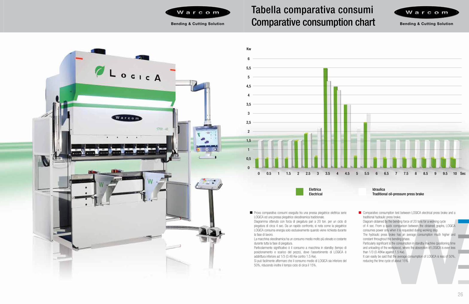
Prova comparativa consumi eseguita tra una pressa piegatrice elettrica serie LOGICA ed una pressa piegatrice oleodinamica tradizionale.Diagramma ottenuto con forza di piegatura pari a 20 ton. per un ciclo di piegatura di circa 4 sec. Da un rapido confronto, si nota come la piegatrice LOGICA consuma energia solo esclusivamente quando viene richiesta durante la fase di lavoro.La macchina oleodinamica ha un consumo medio molto più elevato e costante durante tutta la fase di piegatura.Particolarmente significativo è il consumo a macchina in standby (tempo di posizionamento e scarico del pezzo), dove l’assorbimento di LOGICA è addirittura inferiore ad 1/3 (0.48 Kw contro 1.5 Kw).Si può facilmente affermare che il consumo medio di LOGICA sia inferiore del 50%, riducendo inoltre il tempo ciclo di circa il 15%.
Comparative consumption test between LOGICA electrical press brake and a traditional hydraulic press brake.Diagram obtained by the bending force of 20 tons for a working cycle of 4 sec. From a quick comparison between the obtained graphs, LOGICA consumes power only when it is requested during working step. The hydraulic press brake has an average consumption much higher and constant throughout the bending phase. Particularly significant is the consumption in standby machine (positioning time and unloading of the workpiece), where the absorption of LOGICA is even less than 1/3 (0.48Kw against 1.5 Kw). It can easily be said that the average consumption of LOGICA is less of 50%, reducing the time cycle of about 15%.
Tabella comparativa consumiComparative consumption chart
0 3 6.51.5 4.5 80.5 3.5 72 5 8.5 9.51 4 7.52.5 65.5 9 10
0
0,5
1,5
1
2
2,5
3
3,5
4
4,5
5
5,5
6
Kw
Sec
ElettricaElectrical
IdraulicaTraditional oil-pressure press brake
2624
La serie LOGICA rappresenta un’ottima combinazione di design moderno e raffinato, innovazione ed elevata tecnologia. Il rivoluzionario sistema di trasmissione diretta tra motore e pestone, senza ulteriori organi di rinvio meccanico, rende il sistema estremamente affidabile, preciso, efficiente e silenzioso, con una velocità superiore a qualsiasi altro cinematismo. LOGICA viene fornita con registri altamente performanti, movimentati da pignoni e cremagliere su guide lineari di precisione. È il prodotto ideale per l’esecuzione di piccoli presso piegati in serie con altissima produttività e ripetibilità.
LOGICA represents a great combination between modern and elegant design, innovation and high level technology. The revolutionary direct drive system, between servo motor and upper beam, without any mechanical drive organs, makes the system extremely reliable, accurate, efficient and quiet, with a speed higher than any other kinematic system available. LOGICA is supplied with high performance backgauge, moved by racks and pinions on high accuracy linear guides. This is the perfect machine for small bends in series with high productivity and repeatability.
Prova comparativa consumi eseguita tra una pressa piegatrice elettrica serie LOGICA ed una pressa piegatrice oleodinamica tradizionale.Diagramma ottenuto con forza di piegatura pari a 20 ton. per un ciclo di piegatura di circa 4 sec. Da un rapido confronto, si nota come la piegatrice LOGICA consuma energia solo esclusivamente quando viene richiesta durante la fase di lavoro.La macchina oleodinamica ha un consumo medio molto più elevato e costante durante tutta la fase di piegatura.Particolarmente significativo è il consumo a macchina in standby (tempo di posizionamento e scarico del pezzo), dove l’assorbimento di LOGICA è addirittura inferiore ad 1/3 (0.48 Kw contro 1.5 Kw).Si può facilmente affermare che il consumo medio di LOGICA sia inferiore del 50%, riducendo inoltre il tempo ciclo di circa il 15%.
Comparative consumption test between LOGICA electrical press brake and a traditional hydraulic press brake.Diagram obtained by the bending force of 20 tons for a working cycle of 4 sec. From a quick comparison between the obtained graphs, LOGICA consumes power only when it is requested during working step. The hydraulic press brake has an average consumption much higher and constant throughout the bending phase. Particularly significant is the consumption in standby machine (positioning time and unloading of the workpiece), where the absorption of LOGICA is even less than 1/3 (0.48Kw against 1.5 Kw). It can easily be said that the average consumption of LOGICA is less of 50%, reducing the time cycle of about 15%.
Tabella comparativa consumiComparative consumption chart
0 3 6.51.5 4.5 80.5 3.5 72 5 8.5 9.51 4 7.52.5 65.5 9 10
0
0,5
1,5
1
2
2,5
3
3,5
4
4,5
5
5,5
6
Kw
Sec
ElettricaElectrical
IdraulicaTraditional oil-pressure press brake
R
Z1Z2
X6X5
27 28
Il sistema di movimentazione del pestone è realizzato con doppia guida a cuscinetti a rulli in acciaio temprato e rettificato. I motori applicati su LOGICA sono motori TORQUE calettati direttamente su una vite a ricircolo di sfere ad alta capacità di carico temprata e rettificata. Questo sistema permette di raggiungere una velocità massima di avvicinamento di 270 mm/sec.
The sliding system of the upper beam is made of double hardened and ground roller bearings.The motors equipped on LOGICA are TORQUE motors fitted flush directly on a hardened and ground high loading capacity ball screw. This technical solution permit to reach a working speed of 270 mm/sec.
23
Registro posteriore Backgauge
Il registro posteriore M6 è realizzato con una struttura meccanica molto robusta fissata sulla base della pressa piegatrice. La configurazione standard prevede due assi di movimentazione (X-R) con due torrette di riscontro montate su guide lineari movimentabili dalla parte anteriore della macchina.Su richiesta, è possibile montare torrette supplementari o arrivare alla movimentazione di 6 assi (X-R-Z1-Z2-X5-X6).La trasmissione avviene tramite accoppiamento pignone e cremagliera di alta precisione con scorrimento su guide lineari.
The M6 backgauge model has a sturdy mechanical structure fixed on the base of the press brake. The standard configuration includes 2 axis (X-R) with n.2 finger stops manual sliding, on linear guides, from the frontal part of the machine. On request, it is possible to add extra finger stops or made the backgauge at a configuration up to 6 axis (X-R-Z1-Z2 X5-X6). The transmission is with high precision racks and pinions, sliding on linear guides.
CARATTERISTICHE REGISTRO M6 BACKGAUGE FEATURES
Corsa asse X 800 mm X axis stroke
Velocità asse X 500 mm/sec X axis speed
Risoluzione meccanica +/- 0,05 mm Mechanical resolution
Corsa asse R 150 mm R axis stroke
Velocità asse R 120 mm/sec R axis speed
Risoluzione meccanica +/- 0,05 mm Mechanical resolution
Velocità asse Z 1400 mm/sec Z axis speed
Risoluzione meccanica +/- 0,1 mm Mechanical resolution
Corsa asse X5-X6 +/- 150 mm X5-X6 axis stroke
Velocità asse X5-X6 150 mm/sec X5-X6 axis speed
Risoluzione meccanica +/- 0,1 mm Mechanical resolution
Angolo d’inclinazione massimo asse X6 60° X6 axis maximum tilt angle
Angolo d’inclinazione massimo assi X5-X6 75° X5-X6 maximum tilt angle
X
Sistema di scorrimentoSliding system M6

CARATTERISTICHE REGISTRO M1 BACKGAUGE FEATURES
Corsa asse X 600 mm X axis stroke
Velocità asse X 500 mm/sec X axis speed
Risoluzione Meccanica +/- 0,05 mm Mechanical Resolution
Corsa asse R 150 mm R axis stroke
Velocità asse R 200 mm/sec R axis speed
Risoluzione Meccanica +/- 0,05 mm Mechanical Resolution
Velocità asse Z 1100 mm/sec Z axis speed
Risoluzione Meccanica +/- 0,1 mm Mechanical Resolution
Corsa asse X5-X6 +/- 130 mm X5-X6 axis stroke
Velocità asse X5-X6 150 mm/sec X5-X6 axis speed
Risoluzione Meccanica +/- 0,1 mm Mechanical Resolution
Angolo d’inclinazione massimo asse X6 60° X6 maximum tilt angle
Angolo d’inclinazione massimo assi X5-X6 75° X5-X6 maximum tilt angle
30
31
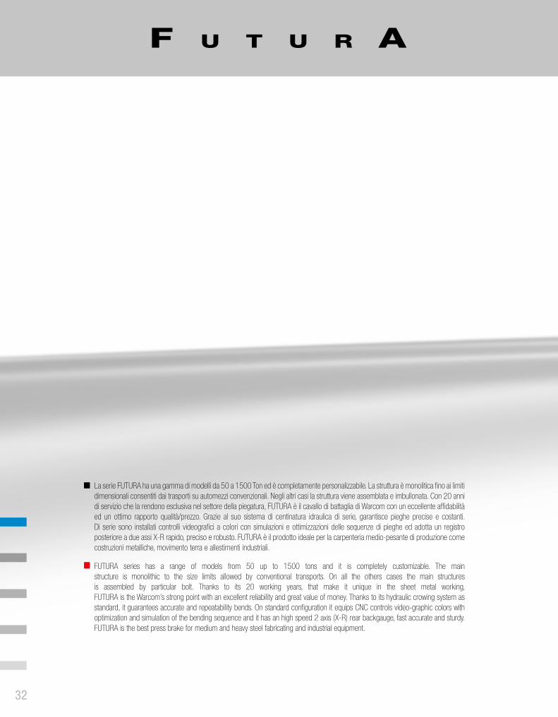
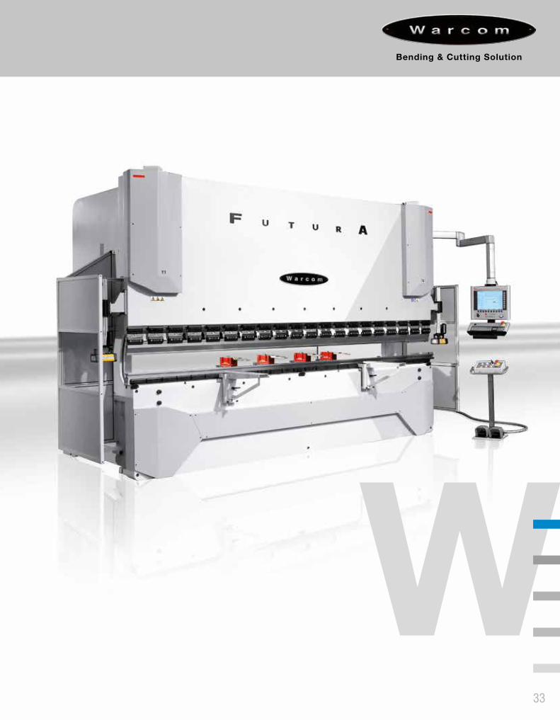
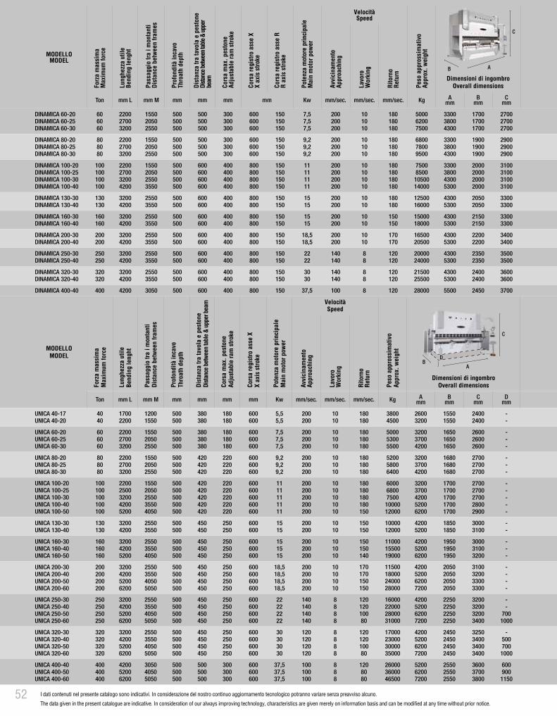
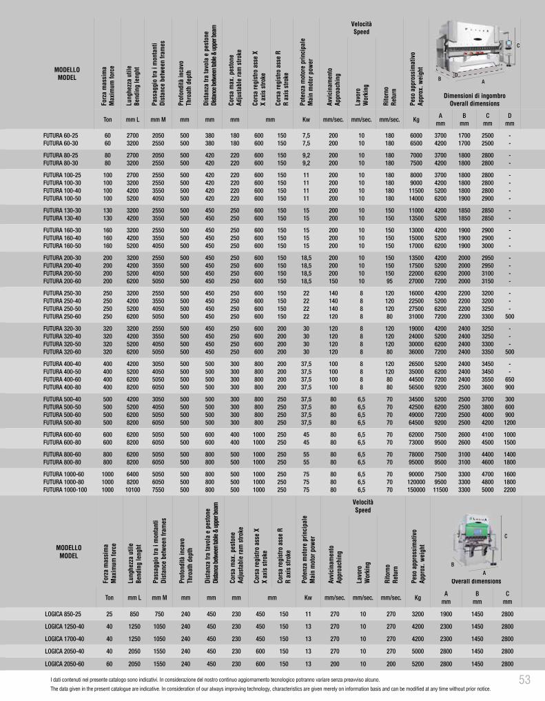
La serie FUTURA ha una gamma di modelli da 50 a 1500 Ton ed è completamente personalizzabile. La struttura è monolitica fino ai limiti dimensionali consentiti dai trasporti su automezzi convenzionali. Negli altri casi la struttura viene assemblata e imbullonata. Con 20 anni di servizio che la rendono esclusiva nel settore della piegatura, FUTURA è il cavallo di battaglia di Warcom con un eccellente affidabilità ed un ottimo rapporto qualità/prezzo. Grazie al suo sistema di centinatura idraulica di serie, garantisce pieghe precise e costanti. Di serie sono installati controlli videografici a colori con simulazioni e ottimizzazioni delle sequenze di pieghe ed adotta un registro posteriore a due assi X-R rapido, preciso e robusto. FUTURA è il prodotto ideale per la carpenteria medio-pesante di produzione come costruzioni metalliche, movimento terra e allestimenti industriali.
FUTURA series has a range of models from 50 up to 1500 tons and it is completely customizable. The main structure is monolithic to the size limits allowed by conventional transports. On all the others cases the main structures is assembled by particular bolt. Thanks to its 20 working years, that make it unique in the sheet metal working, FUTURA is the Warcom’s strong point with an excellent reliability and great value of money. Thanks to its hydraulic crowing system as standard, it guarantees accurate and repeatability bends. On standard configuration it equips CNC controls video-graphic colors with optimization and simulation of the bending sequence and it has an high speed 2 axis (X-R) rear backgauge, fast accurate and sturdy. FUTURA is the best press brake for medium and heavy steel fabricating and industrial equipment.
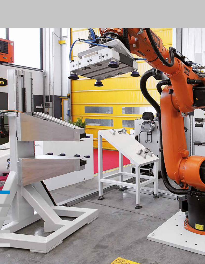
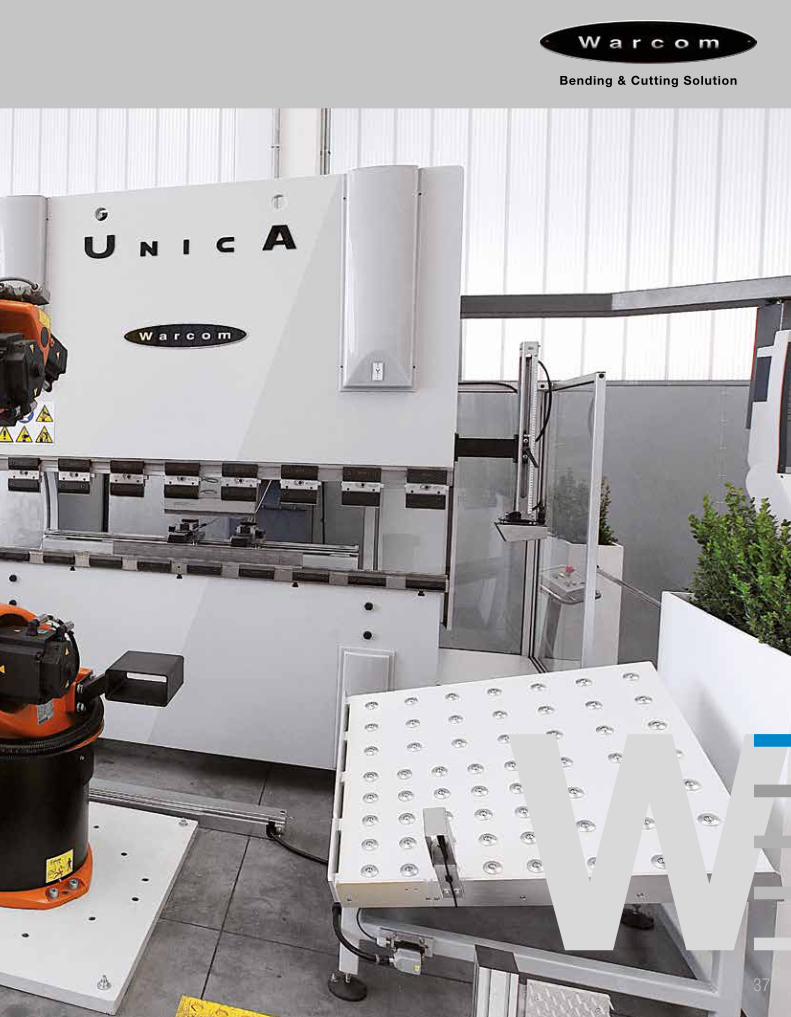
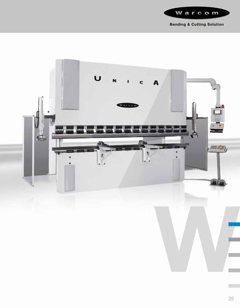
Con questa gamma di presse piegatrici sincronizzate, Warcom vuole proporsi ad un target di mercato che non richiede prestazioni elevatissime, ma senza rinunciare alla qualità e alla solidità costruttiva. La serie UNICA possiede l’equipaggiamento di base per la piegatura, montando di serie controlli alfanumerici a 3 assi (Y1-Y2-X), un registro ad un asse X con riscontri movimentabili manualmente. UNICA è una pressa piegatrice sincronizzata semplice ma performante, alla portata di tutti. Particolarmente indicata per lavorazioni ripetitive, è anche la macchina ideale per officine di manutenzione, serramentisti e lavorazioni di carpenteria leggera.
By this series, Warcom wants to focus also to a market where it is not requested high performance, but without sacrificing the quality and the sturdy construction. As standard, UNICA includes a basic equipment of 3 axis (Y1-Y2-X) alphanumeric CNC control and a X axis backgauge with manual finger stops. UNICA is a synchronized press brake easy to use but very performing, useful for everyone. Suitable for repetitive works, it is also the best press brake for maintenance shops and sheet metal working.
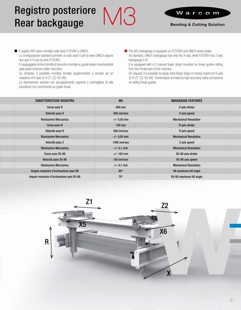
CARATTERISTICHE REGISTRO M3 BACKGAUGE FEATURES
Corsa asse X 600 mm X axis stroke
Velocità asse X 500 mm/sec X axis speed
Risoluzione Meccanica +/- 0,05 mm Mechanical Resolution
Corsa asse R 130 mm R axis stroke
Velocità asse R 200 mm/sec R axis speed
Risoluzione Meccanica +/- 0,05 mm Mechanical Resolution
Velocità asse Z 1400 mm/sec Z axis speed
Risoluzione Meccanica +/- 0,1 mm Mechanical Resolution
Corsa asse X5-X6 +/- 150 mm X5-X6 axis stroke
Velocità asse X5-X6 150 mm/sec X5-X6 axis speed
Risoluzione Meccanica +/- 0,1 mm Mechanical Resolution
Angolo massimo d’inclinazione asse X6 60° X6 maximum tilt angle
Angolo massimo d’inclinazione assi X5-X6 75° X5-X6 maximum tilt angle
MODELLOMODEL
Forz
a m
assi
ma
Max
imum
forc
e
Lung
hezz
a ut
ileBe
ndin
g le
nght
Pass
aggi
o tra
i m
onta
nti
Dist
ance
bet
wee
n fra
mes
Prof
ondi
tà in
cavo
Thro
ath
dept
h
Dist
anza
tra
tavo
la e
pes
tone
Dista
nce
betw
een
tabl
e &
uppe
r bea
m
Cors
a m
ax. p
esto
neAd
just
able
ram
stro
ke
Cors
a re
gist
ro a
sse
XX
axis
stro
ke
Pote
nza
mot
ore
prin
cipa
leM
ain
mot
or p
ower
VelocitàSpeed
Peso
app
ross
imat
ivo
Appr
ox. w
eigh
t
Dimensioni di ingombroOverall dimensionsAv
vici
nam
ento
Appr
oach
ing
Lavo
roW
orki
ng
Rito
rno
Retu
rn
Ton mm L mm M mm mm mm mm Kw mm/sec. mm/sec. mm/sec. Kg Amm
Bmm
Cmm
Dmm
UNICA 40-17UNICA 40-20
4040
17002200
12001550
500500
380380
180180
600600
5,55,5
200200
1010
180180
38004500
26003200
15501550
24002400
--
UNICA 60-20UNICA 60-25UNICA 60-30
606060
220027003200
155020502550
500500500
380380380
180180180
600600600
7,57,57,5
200200200
101010
180180180
500053005500
320037004200
165016501650
260026002600
---
UNICA 80-20UNICA 80-25UNICA 80-30
808080
220027003200
155020502550
500500500
420420420
220220220
600600600
9,29,29,2
200200200
101010
180180180
520058006400
320037004200
168016801680
270027002700
---
UNICA 100-20UNICA 100-25UNICA 100-30UNICA 100-40UNICA 100-50
100100100100100
22002500320042005200
15502050255035504050
500500500500500
420420420420420
220220220220220
600600600600600
1111111111
200200200200200
1010101010
180180180180150
600068007500
1000012000
32003700420052006200
17001700170017001700
27002700270028002900
-----
UNICA 130-30UNICA 130-40
130130
32004200
25503550
500500
450450
250250
600600
1515
200200
1010
150150
1000012000
42005200
18501850
30003100
--
UNICA 160-30UNICA 160-40UNICA 160-50
160160160
320042005200
255035504050
500500500
450450450
250250250
600600600
151515
200200200
101010
150150140
110001550019000
420052006200
195019501950
300031003200
---
UNICA 200-30UNICA 200-40UNICA 200-50UNICA 200-60
200200200200
3200420052006200
2550355040505050
500500500500
450450450450
250250250250
600600600600
18,518,518,518,5
200200200200
10101010
170170150150
11500180002400028000
4200520062007200
2050205020502050
3100320033003300
----
UNICA 250-30UNICA 250-40UNICA 250-50UNICA 250-60
250250250250
3200420052006200
2550355040505050
500500500500
450450450450
250250250250
600600600600
22222222
140140140140
8888
12012010080
16000220002800031000
4200520062007200
2250225022502250
3200320032003400
--
7001000
UNICA 320-30UNICA 320-40UNICA 320-50UNICA 320-60
320320320320
3200420052006200
2550355040505050
500500500500
450450450450
250250250250
600600600600
30303030
120120120120
8888
12012010080
17000230003000035000
4200520062007200
2450245024502450
3250340034003400
-500700
1000
UNICA 400-40UNICA 400-50UNICA 400-60
400400400
420052006200
305040505050
500500500
500500500
300300300
600600600
37,537,537,5
100100100
888
1208080
260003600046500
520062007200
255025502550
360037003800
600900
1150
MODELLOMODEL
Forz
a m
assi
ma
Max
imum
forc
e
Lung
hezz
a ut
ileBe
ndin
g le
nght
Pass
aggi
o tra
i m
onta
nti
Dist
ance
bet
wee
n fra
mes
Prof
ondi
tà in
cavo
Thro
ath
dept
h
Dist
anza
tra
tavo
la e
pes
tone
Dista
nce b
etwee
n tab
le &
uppe
r be
am
Cors
a m
ax. p
esto
neAd
just
able
ram
stro
ke
Cors
a re
gist
ro a
sse
XX
axis
stro
ke
Cors
a re
gist
ro a
sse
RR
axis
stro
ke
Pote
nza
mot
ore
prin
cipa
leM
ain
mot
or p
ower
VelocitàSpeed
Peso
app
ross
imat
ivo
Appr
ox. w
eigh
t
Dimensioni di ingombroOverall dimensionsAv
vici
nam
ento
Appr
oach
ing
Lavo
roW
orki
ng
Rito
rno
Retu
rn
Ton mm L mm M mm mm mm mm Kw mm/sec. mm/sec. mm/sec. Kg Amm
Bmm
Cmm
DINAMICA 60-20DINAMICA 60-25DINAMICA 60-30
606060
220027003200
155020502550
500500500
500500500
300300300
600600600
150150150
7,57,57,5
200200200
101010
180180180
500062007500
330038004300
170017001700
270027002700
DINAMICA 80-20DINAMICA 80-25DINAMICA 80-30
808080
220027003200
155020502550
500500500
500500500
300300300
600600600
150150150
9,29,29,2
200200200
101010
180180180
680078009500
330038004300
190019001900
290029002900
DINAMICA 100-20DINAMICA 100-25DINAMICA 100-30DINAMICA 100-40
100100100100
2200270032004200
1550205025503550
500500500500
600600600600
400400400400
800800800800
150150150150
11111111
200200200200
10101010
180180180180
75008500
1050014000
3300380043005300
2000200020002000
3100310031003100
DINAMICA 130-30DINAMICA 130-40
130130
32004200
25503550
500500
600600
400400
800800
150150
1515
200200
1010
180180
1250016000
43005300
20502050
33003300
DINAMICA 160-30DINAMICA 160-40
160160
32004200
25503550
500500
600600
400400
800800
150150
1515
200200
1010
150150
1500018000
43005300
21502150
33003300
DINAMICA 200-30DINAMICA 200-40
200200
32004200
25503550
500500
600600
400400
800800
150150
18,518,5
200200
1010
170170
1650020500
43005300
22002200
34003400
DINAMICA 250-30DINAMICA 250-40
250250
32004200
25503550
500500
600600
400400
800800
150150
2222
140140
88
120120
2000024000
43005300
23502350
35003500
DINAMICA 320-30DINAMICA 320-40
320320
32004200
25503550
500500
600600
400400
800800
150150
3030
140140
88
120120
2150025500
43005300
24002400
36003600
DINAMICA 400-40 400 4200 3050 500 600 400 800 150 37,5 100 8 120 28000 5500 2450 3700
MODELLOMODEL
Forz
a m
assi
ma
Max
imum
forc
e
Lung
hezz
a ut
ileBe
ndin
g le
nght
Pass
aggi
o tra
i m
onta
nti
Dist
ance
bet
ween
fram
es
Prof
ondi
tà in
cavo
Thro
ath
dept
h
Dist
anza
tra
tavo
la e
pes
tone
Dista
nce b
etwee
n tab
le &
uppe
r bea
m
Cors
a m
ax. p
esto
neAd
just
able
ram
stro
ke
Cors
a re
gist
ro a
sse
XX
axis
stro
ke
Cors
a re
gist
ro a
sse
RR
axis
stro
ke
Pote
nza
mot
ore
prin
cipa
leM
ain
mot
or p
ower
VelocitàSpeed
Peso
app
ross
imat
ivo
Appr
ox. w
eigh
t
Dimensioni di ingombroOverall dimensionsAv
vici
nam
ento
Appr
oach
ing
Lavo
roW
orki
ng
Rito
rno
Retu
rn
Ton mm L mm M mm mm mm mm Kw mm/sec. mm/sec. mm/sec. KgA
mmB
mmC
mmD
mm
FUTURA 60-25FUTURA 60-30
6060
27003200
20502550
500500
380380
180180
600600
150150
7,57,5
200200
1010
180180
60006500
37004200
17001700
25002500
--
FUTURA 80-25FUTURA 80-30
8080
27003200
20502550
500500
420420
220220
600600
150150
9,29,2
200200
1010
180180
70007500
37004200
18001800
28002800
--
FUTURA 100-25FUTURA 100-30FUTURA 100-40FUTURA 100-50
100100100100
2700320042005200
2550255035504050
500500500500
420420420420
220220220220
600600600600
150150150150
11111111
200200200200
10101010
180180180180
80009000
1150014000
3700420052006200
1800180018001900
2800280028002900
----
FUTURA 130-30FUTURA 130-40
130130
32004200
25503550
500500
450450
250250
600600
150150
1515
200200
1010
150150
1100013500
42005200
18501850
28502850
--
FUTURA 160-30FUTURA 160-40FUTURA 160-50
160160160
320042005200
255035504050
500500500
450450450
250250250
600600600
150150150
151515
200200200
101010
150150150
130001500017000
420052006200
190019001900
290029003000
---
FUTURA 200-30FUTURA 200-40FUTURA 200-50FUTURA 200-60
200200200200
3200420052006200
2550355040505050
500500500500
450450450450
250250250250
600600600600
150150150150
18,518,518,518,5
200200200150
10101010
15015015095
13500175002200027000
4200520062007200
2000200020002000
2950295031003150
----
FUTURA 250-30FUTURA 250-40FUTURA 250-50FUTURA 250-60
250250250250
3200420052006200
2550355040505050
500500500500
450450450450
250250250250
600600600600
150150150150
22222222
140140140120
8888
12012012080
16000225002750031000
4200520062007200
2200220022002200
3200320032503300
---
500
FUTURA 320-30FUTURA 320-40FUTURA 320-50FUTURA 320-60
320320320320
3200420052006200
2550355040505050
500500500500
450450450450
250250250250
600600600600
200200200200
30303030
120120120120
8888
12012012080
19000240003000036000
4200520062007200
2400240024002400
3250325033003350
---
500
FUTURA 400-40FUTURA 400-50FUTURA 400-60FUTURA 400-80
400400400400
4200520062008200
3050405050506050
500500500500
500500500500
300300300300
800800800800
200200200200
37,537,537,537,5
100100100100
8888
1201208080
26500350004450056500
5200620072009200
2400240024002500
3450345035503600
--
650900
FUTURA 500-40FUTURA 500-50FUTURA 500-60FUTURA 500-80
500500500500
4200520062008200
3050405050506050
500500500500
500500500500
300300300300
800800800800
250250250250
37,537,537,537,5
80808080
6,56,56,56,5
70707070
34500425004900064500
5200620072009200
2500250025002500
3700380040004200
300600900
1200
FUTURA 600-60FUTURA 600-80
600600
62008200
50506050
500500
600600
400400
10001000
250250
4545
8080
6,56,5
7070
6200073000
75009500
26002600
41004500
10001500
FUTURA 800-60FUTURA 800-80
800800
62008200
50506050
500500
800800
500500
10001000
250250
5555
8080
6,56,5
7070
7800095000
75009500
31003100
44004600
14001800
FUTURA 1000-60FUTURA 1000-80FUTURA 1000-100
100010001000
64008200
10100
505060507550
500500500
800800800
500500500
100010001000
250250250
757575
808080
6,56,56,5
707070
90000120000150000
75009500
11500
330033003300
470048005000
160018002200
MODELLOMODEL
Forz
a m
assi
ma
Max
imum
forc
e
Lung
hezz
a ut
ileBe
ndin
g le
nght
Pass
aggi
o tra
i m
onta
nti
Dist
ance
bet
wee
n fra
mes
Prof
ondi
tà in
cavo
Thro
ath
dept
h
Dist
anza
tra
tavo
la e
pes
tone
Dista
nce
betw
een
tabl
e &
uppe
r bea
m
Cors
a m
ax. p
esto
neAd
just
able
ram
stro
ke
Cors
a re
gist
ro a
sse
XX
axis
stro
ke
Pote
nza
mot
ore
prin
cipa
leM
ain
mot
or p
ower
VelocitàSpeed
Peso
app
ross
imat
ivo
Appr
ox. w
eigh
t
Dimensioni di ingombroOverall dimensionsAv
vici
nam
ento
Appr
oach
ing
Lavo
roW
orki
ng
Rito
rno
Retu
rn
Ton mm L mm M mm mm mm mm Kw mm/sec. mm/sec. mm/sec. Kg Amm
Bmm
Cmm
Dmm
UNICA 40-17UNICA 40-20
4040
17002200
12001550
500500
380380
180180
600600
5,55,5
200200
1010
180180
38004500
26003200
15501550
24002400
--
UNICA 60-20UNICA 60-25UNICA 60-30
606060
220027003200
155020502550
500500500
380380380
180180180
600600600
7,57,57,5
200200200
101010
180180180
500053005500
320037004200
165016501650
260026002600
---
UNICA 80-20UNICA 80-25UNICA 80-30
808080
220027003200
155020502550
500500500
420420420
220220220
600600600
9,29,29,2
200200200
101010
180180180
520058006400
320037004200
168016801680
270027002700
---
UNICA 100-20UNICA 100-25UNICA 100-30UNICA 100-40UNICA 100-50
100100100100100
22002500320042005200
15502050255035504050
500500500500500
420420420420420
220220220220220
600600600600600
1111111111
200200200200200
1010101010
180180180180150
6000680075001000012000
32003700420052006200
17001700170017001700
27002700270028002900
-----
UNICA 130-30UNICA 130-40
130130
32004200
25503550
500500
450450
250250
600600
1515
200200
1010
150150
1000012000
42005200
18501850
30003100
--
UNICA 160-30UNICA 160-40UNICA 160-50
160160160
320042005200
255035504050
500500500
450450450
250250250
600600600
151515
200200200
101010
150150140
110001550019000
420052006200
195019501950
300031003200
---
UNICA 200-30UNICA 200-40UNICA 200-50UNICA 200-60
200200200200
3200420052006200
2550355040505050
500500500500
450450450450
250250250250
600600600600
18,518,518,518,5
200200200200
10101010
170170150150
11500180002400028000
4200520062007200
2050205020502050
3100320033003300
----
UNICA 250-30UNICA 250-40UNICA 250-50UNICA 250-60
250250250250
3200420052006200
2550355040505050
500500500500
450450450450
250250250250
600600600600
22222222
140140140140
8888
12012010080
16000220002800031000
4200520062007200
2250225022502250
3200320032003400
--
7001000
UNICA 320-30UNICA 320-40UNICA 320-50UNICA 320-60
320320320320
3200420052006200
2550355040505050
500500500500
450450450450
250250250250
600600600600
30303030
120120120120
8888
12012010080
17000230003000035000
4200520062007200
2450245024502450
3250340034003400
-5007001000
UNICA 400-40UNICA 400-50UNICA 400-60
400400400
420052006200
305040505050
500500500
500500500
300300300
600600600
37,537,537,5
100100100
888
1208080
260003600046500
520062007200
255025502550
360037003800
6009001150
MODELLOMODEL
Forz
a m
assi
ma
Max
imum
forc
e
Lung
hezz
a ut
ileBe
ndin
g le
nght
Pass
aggi
o tra
i m
onta
nti
Dist
ance
bet
wee
n fra
mes
Prof
ondi
tà in
cavo
Thro
ath
dept
h
Dist
anza
tra
tavo
la e
pes
tone
Dista
nce b
etwee
n tab
le &
uppe
r be
am
Cors
a m
ax. p
esto
neAd
just
able
ram
stro
ke
Cors
a re
gist
ro a
sse
XX
axis
stro
ke
Cors
a re
gist
ro a
sse
RR
axis
stro
ke
Pote
nza
mot
ore
prin
cipa
leM
ain
mot
or p
ower
VelocitàSpeed
Peso
app
ross
imat
ivo
Appr
ox. w
eigh
t
Dimensioni di ingombroOverall dimensionsAv
vici
nam
ento
Appr
oach
ing
Lavo
roW
orki
ng
Rito
rno
Retu
rn
Ton mm L mm M mm mm mm mm Kw mm/sec. mm/sec. mm/sec. Kg Amm
Bmm
Cmm
DINAMICA 60-20DINAMICA 60-25DINAMICA 60-30
606060
220027003200
155020502550
500500500
500500500
300300300
600600600
150150150
7,57,57,5
200200200
101010
180180180
500062007500
330038004300
170017001700
270027002700
DINAMICA 80-20DINAMICA 80-25DINAMICA 80-30
808080
220027003200
155020502550
500500500
500500500
300300300
600600600
150150150
9,29,29,2
200200200
101010
180180180
680078009500
330038004300
190019001900
290029002900
DINAMICA 100-20DINAMICA 100-25DINAMICA 100-30DINAMICA 100-40
100100100100
2200270032004200
1550205025503550
500500500500
600600600600
400400400400
800800800800
150150150150
11111111
200200200200
10101010
180180180180
750085001050014000
3300380043005300
2000200020002000
3100310031003100
DINAMICA 130-30DINAMICA 130-40
130130
32004200
25503550
500500
600600
400400
800800
150150
1515
200200
1010
180180
1250016000
43005300
20502050
33003300
DINAMICA 160-30DINAMICA 160-40
160160
32004200
25503550
500500
600600
400400
800800
150150
1515
200200
1010
150150
1500018000
43005300
21502150
33003300
DINAMICA 200-30DINAMICA 200-40
200200
32004200
25503550
500500
600600
400400
800800
150150
18,518,5
200200
1010
170170
1650020500
43005300
22002200
34003400
DINAMICA 250-30DINAMICA 250-40
250250
32004200
25503550
500500
600600
400400
800800
150150
2222
140140
88
120120
2000024000
43005300
23502350
35003500
DINAMICA 320-30DINAMICA 320-40
320320
32004200
25503550
500500
600600
400400
800800
150150
3030
140140
88
120120
2150025500
43005300
24002400
36003600
DINAMICA 400-40 400 4200 3050 500 600 400 800 150 37,5 100 8 120 28000 5500 2450 3700
MODELLOMODEL
Forz
a m
assi
ma
Max
imum
forc
e
Lung
hezz
a ut
ileBe
ndin
g le
nght
Pass
aggi
o tra
i m
onta
nti
Dist
ance
bet
ween
fram
es
Prof
ondi
tà in
cavo
Thro
ath
dept
h
Dist
anza
tra
tavo
la e
pes
tone
Dista
nce b
etwee
n tab
le &
uppe
r bea
m
Cors
a m
ax. p
esto
neAd
just
able
ram
stro
ke
Cors
a re
gist
ro a
sse
XX
axis
stro
ke
Cors
a re
gist
ro a
sse
RR
axis
stro
ke
Pote
nza
mot
ore
prin
cipa
leM
ain
mot
or p
ower
VelocitàSpeed
Peso
app
ross
imat
ivo
Appr
ox. w
eigh
t
Dimensioni di ingombroOverall dimensionsAv
vici
nam
ento
Appr
oach
ing
Lavo
roW
orki
ng
Rito
rno
Retu
rn
Ton mm L mm M mm mm mm mm Kw mm/sec. mm/sec. mm/sec. KgA
mmB
mmC
mmD
mm
FUTURA 60-25FUTURA 60-30
6060
27003200
20502550
500500
380380
180180
600600
150150
7,57,5
200200
1010
180180
60006500
37004200
17001700
25002500
--
FUTURA 80-25FUTURA 80-30
8080
27003200
20502550
500500
420420
220220
600600
150150
9,29,2
200200
1010
180180
70007500
37004200
18001800
28002800
--
FUTURA 100-25FUTURA 100-30FUTURA 100-40FUTURA 100-50
100100100100
2700320042005200
2550255035504050
500500500500
420420420420
220220220220
600600600600
150150150150
11111111
200200200200
10101010
180180180180
80009000
1150014000
3700420052006200
1800180018001900
2800280028002900
----
FUTURA 130-30FUTURA 130-40
130130
32004200
25503550
500500
450450
250250
600600
150150
1515
200200
1010
150150
1100013500
42005200
18501850
28502850
--
FUTURA 160-30FUTURA 160-40FUTURA 160-50
160160160
320042005200
255035504050
500500500
450450450
250250250
600600600
150150150
151515
200200200
101010
150150150
130001500017000
420052006200
190019001900
290029003000
---
FUTURA 200-30FUTURA 200-40FUTURA 200-50FUTURA 200-60
200200200200
3200420052006200
2550355040505050
500500500500
450450450450
250250250250
600600600600
150150150150
18,518,518,518,5
200200200150
10101010
15015015095
13500175002200027000
4200520062007200
2000200020002000
2950295031003150
----
FUTURA 250-30FUTURA 250-40FUTURA 250-50FUTURA 250-60
250250250250
3200420052006200
2550355040505050
500500500500
450450450450
250250250250
600600600600
150150150150
22222222
140140140120
8888
12012012080
16000225002750031000
4200520062007200
2200220022002200
3200320032503300
---
500
FUTURA 320-30FUTURA 320-40FUTURA 320-50FUTURA 320-60
320320320320
3200420052006200
2550355040505050
500500500500
450450450450
250250250250
600600600600
200200200200
30303030
120120120120
8888
12012012080
19000240003000036000
4200520062007200
2400240024002400
3250325033003350
---
500
FUTURA 400-40FUTURA 400-50FUTURA 400-60FUTURA 400-80
400400400400
4200520062008200
3050405050506050
500500500500
500500500500
300300300300
800800800800
200200200200
37,537,537,537,5
100100100100
8888
1201208080
26500350004450056500
5200620072009200
2400240024002500
3450345035503600
--
650900
FUTURA 500-40FUTURA 500-50FUTURA 500-60FUTURA 500-80
500500500500
4200520062008200
3050405050506050
500500500500
500500500500
300300300300
800800800800
250250250250
37,537,537,537,5
80808080
6,56,56,56,5
70707070
34500425004900064500
5200620072009200
2500250025002500
3700380040004200
300600900
1200
FUTURA 600-60FUTURA 600-80
600600
62008200
50506050
500500
600600
400400
10001000
250250
4545
8080
6,56,5
7070
6200073000
75009500
26002600
41004500
10001500
FUTURA 800-60FUTURA 800-80
800800
62008200
50506050
500500
800800
500500
10001000
250250
5555
8080
6,56,5
7070
7800095000
75009500
31003100
44004600
14001800
FUTURA 1000-60FUTURA 1000-80FUTURA 1000-100
100010001000
6400820010100
505060507550
500500500
800800800
500500500
100010001000
250250250
757575
808080
6,56,56,5
707070
90000120000150000
75009500
11500
330033003300
470048005000
160018002200
MODELLOMODEL
Forz
a m
assi
ma
Max
imum
forc
e
Lung
hezz
a ut
ileBe
ndin
g le
nght
Pass
aggi
o tra
i m
onta
nti
Dist
ance
bet
ween
fram
es
Prof
ondi
tà in
cavo
Thro
ath
dept
h
Dist
anza
tra
tavo
la e
pes
tone
Dista
nce b
etwee
n tab
le &
uppe
r bea
m
Cors
a m
ax. p
esto
neAd
just
able
ram
stro
ke
Cors
a re
gist
ro a
sse
XX
axis
stro
ke
Cors
a re
gist
ro a
sse
RR
axis
stro
ke
Pote
nza
mot
ore
prin
cipa
leM
ain
mot
or p
ower
VelocitàSpeed
Peso
app
ross
imat
ivo
Appr
ox. w
eigh
t
Dimensioni di ingombroOverall dimensionsAv
vici
nam
ento
Appr
oach
ing
Lavo
roW
orki
ng
Rito
rno
Retu
rn
Ton mm L mm M mm mm mm mm Kw mm/sec. mm/sec. mm/sec. KgA
mmB
mmC
mm
LOGICA 850-25 25 850 750 240 450 230 450 150 11 270 10 270 3200 1900 1450 2800
LOGICA 1250-40 40 1250 1050 240 450 230 450 150 13 270 10 270 4200 2300 1450 2800
LOGICA 1700-40 40 1250 1050 240 450 230 450 150 13 270 10 270 4200 2300 1450 2800
LOGICA 2050-40 40 2050 1550 240 450 230 600 150 13 270 10 270 5000 2800 1450 2800
LOGICA 2050-60 60 2050 1550 240 450 230 600 150 13 200 10 200 5200 2800 1450 2800
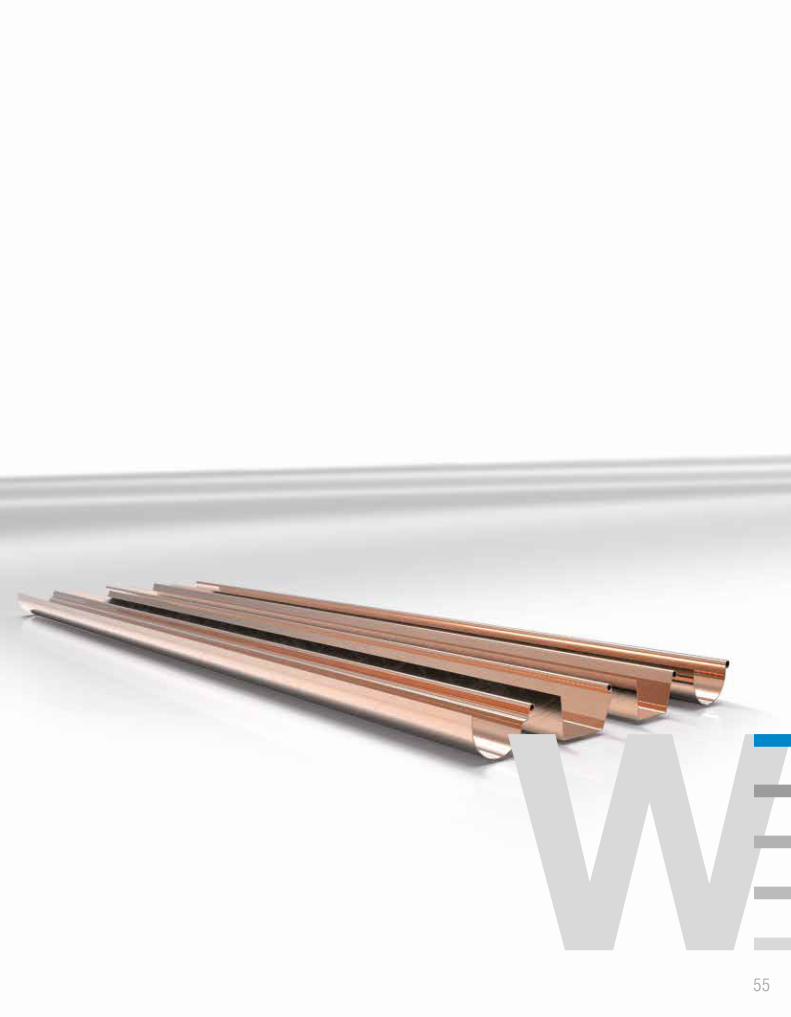
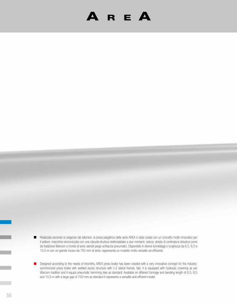
Realizzata secondo le esigenze dei lattonieri, la presa piegatrice delle serie AREA è stata creata con un concetto molto innovativo per il settore: macchina sincronizzata con una robusta struttura elettrosaldata a due montanti, veloce, dotata di centinatura idraulica come da tradizione Warcom e monta di serie utensili piega-schiaccia pneumatici. Disponibile in diversi tonnellaggi e lunghezza da 6,5, 8,5 e 10,5 m con un grande incavo da 750 mm di serie, rappresenta un modello molto versatile ed efficiente.
Designed according to the needs of tinsmiths, AREA press brake has been created with a very innovative concept for the industry: synchronized press brake with welded sturdy structure with n.2 lateral frames, fast, it is equipped with hydraulic crowning as per Warcom tradition and it equips pneumatic hemming dies as standard. Available on different tonnage and bending length of 6,5, 8,5 and 10,5 m with a large gap of 750 mm as standard it represents a versatile and efficient model.
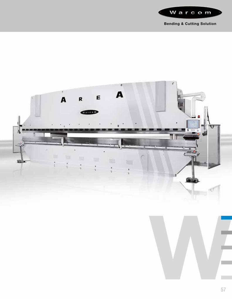
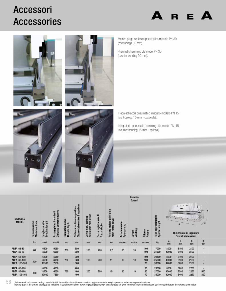
MODELLOMODEL
Forz
a m
assi
ma
Max
imum
forc
e
Lung
hezz
a ut
ileBe
ndin
g le
nght
Pass
aggi
o tra
i m
onta
nti
Dist
ance
bet
ween
fram
es
Prof
ondi
tà in
cavo
Thro
ath
dept
h
Dist
anza
tra
tavo
la e
pes
tone
Dista
nce b
etwee
n tab
le &
uppe
r bea
m
Cors
a m
ax. p
esto
neAd
just
able
ram
stro
ke
Cors
a re
gist
ro a
sse
RR
axis
stro
ke
Pote
nza
mot
ore
prin
cipa
leM
ain
mot
or p
ower
VelocitàSpeed
Peso
app
ross
imat
ivo
Appr
ox. w
eigh
t
Dimensioni di ingombroOverall dimensionsAv
vici
nam
ento
Appr
oach
ing
Lavo
roW
orki
ng
Rito
rno
Retu
rn
Ton mm L mm M mm mm mm mm Kw mm/sec. mm/sec. mm/sec. KgA
mmB
mmC
mmD
mm
AREA 65-80AREA 85-80
8065008500
50506050
750380380
180 200 9,2 80 10100100
1700021500
800010000
31003100
21002100
--
AREA 65-100AREA 85-100AREA 105-100
100
6500850010500
505060507550
750380380380
180 200 11 80 1010010070
205002500030000
80001000012000
310031003200
210021002100
---
AREA 65-160AREA 85-160AREA 105-160
160
6500850010500
455060507550
750400400400
200 200 15 80 10808070
230002700035000
80001000012000
320032003400
225022502250
-500800
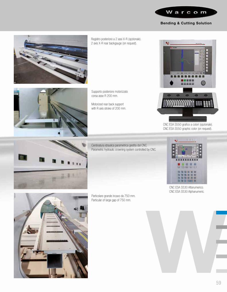
MODELLOMODEL
Forz
a m
assi
ma
Max
imum
forc
e
Lung
hezz
a ut
ileBe
ndin
g le
nght
Pass
aggi
o tra
i m
onta
nti
Dist
ance
bet
ween
fram
es
Prof
ondi
tà in
cavo
Thro
ath
dept
h
Dist
anza
tra
tavo
la e
pes
tone
Dista
nce b
etwee
n tab
le &
uppe
r bea
m
Cors
a m
ax. p
esto
neAd
just
able
ram
stro
ke
Cors
a re
gist
ro a
sse
RR
axis
stro
ke
Pote
nza
mot
ore
prin
cipa
leM
ain
mot
or p
ower
VelocitàSpeed
Peso
app
ross
imat
ivo
Appr
ox. w
eigh
t
Dimensioni di ingombroOverall dimensionsAv
vici
nam
ento
Appr
oach
ing
Lavo
roW
orki
ng
Rito
rno
Retu
rn
Ton mm L mm M mm mm mm mm Kw mm/sec. mm/sec. mm/sec. KgA
mmB
mmC
mmD
mm
AREA 65-80AREA 85-80
8065008500
50506050
750380380
180 200 9,2 80 10100100
1700021500
800010000
31003100
21002100
--
AREA 65-100AREA 85-100AREA 105-100
100
65008500
10500
505060507550
750380380380
180 200 11 80 1010010070
205002500030000
80001000012000
310031003200
210021002100
---
AREA 65-160AREA 85-160AREA 105-160
160
65008500
10500
455060507550
750400400400
200 200 15 80 10808070
230002700035000
80001000012000
320032003400
225022502250
-500800
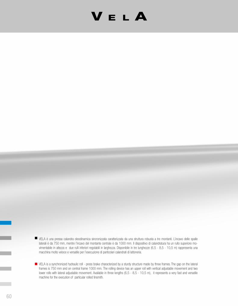
VELA è una pressa calandra oleodinamica sincronizzata caratterizzata da una struttura robusta a tre montanti. L’incavo delle spalle laterali è da 750 mm, mentre l’incavo del montante centrale è da 1000 mm. Il dispositivo di calandratura ha un rullo superiore mo-vimentabile in altezza e due rulli inferiori regolabili in larghezza. Disponibile in tre lunghezze (6,5 - 8,5 - 10,5 m) rappresenta una macchina molto veloce e versatile per l’esecuzione di particolari calandrati di lattoneria.
VELA is a synchronized hydraulic roll - press brake characterized by a sturdy structure made by three frames. The gap on the lateral frames is 750 mm and on central frame 1000 mm. The rolling device has an upper roll with vertical adjustable movement and two lower rolls with lateral adjustable movement. Available in three lengths (6,5 - 8,5 - 10,5 m), it represents a very fast and versatile machine for the execution of particular rolled tinsmith.
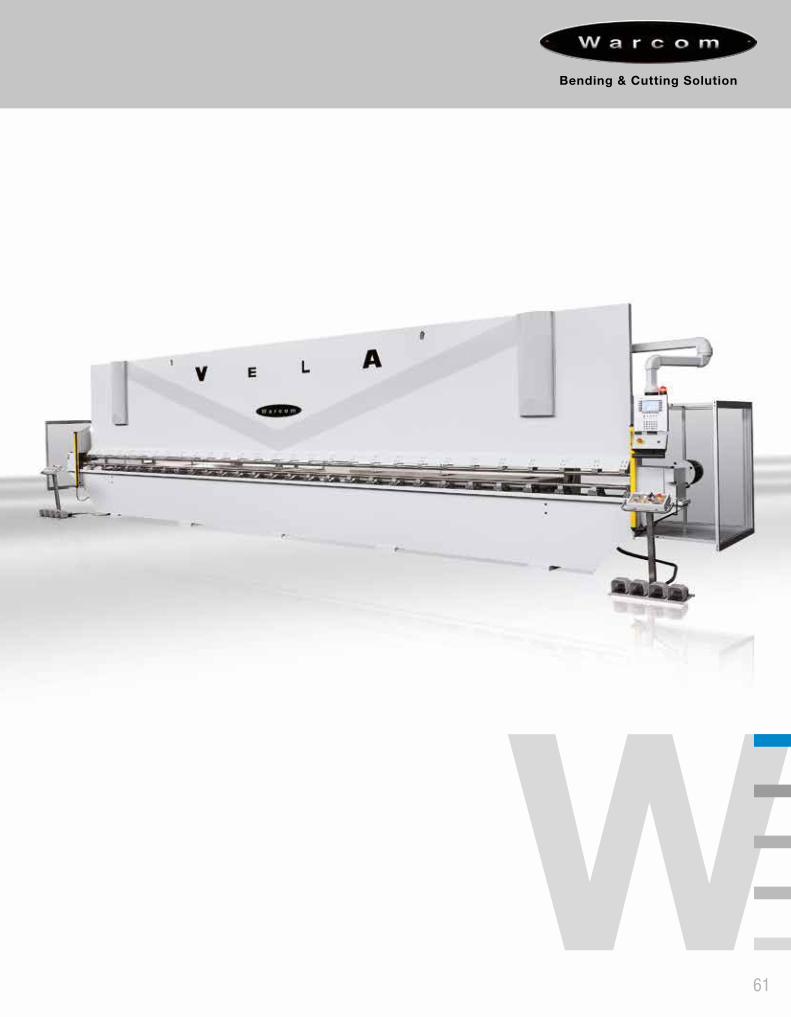
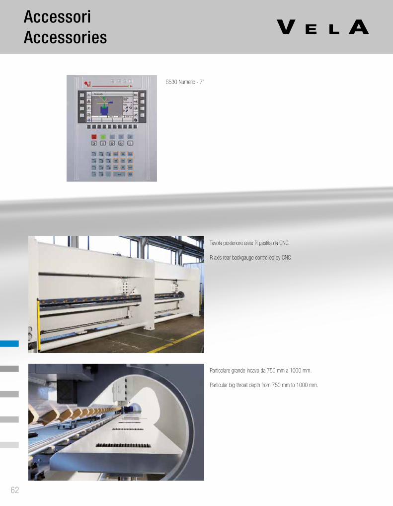
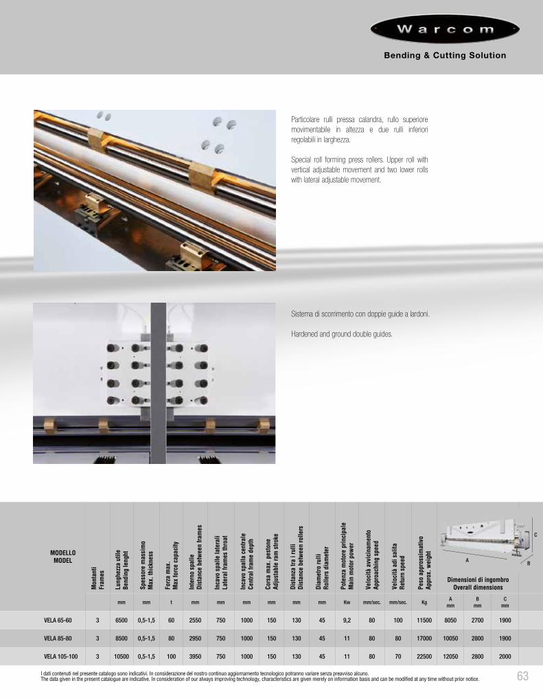
MODELLOMODEL
Mon
tant
iFr
ames
Lung
hezz
a ut
ileBe
ndin
g le
nght
Spes
sore
mas
sim
oM
ax. t
hick
ness
Forz
a m
ax.
Max
forc
e ca
paci
ty
Inte
rno
spal
leDi
stan
ce b
etwe
en fr
ames
Inca
vo s
palle
late
rali
Late
ral f
ram
es th
roat
Inca
vo s
palla
cen
trale
Cent
ral f
ram
e de
pth
Cors
a m
ax. p
esto
neAd
just
able
ram
stro
ke
Dist
anza
tra
i rul
liDi
stan
ce b
etwe
en ro
llers
Velo
cità
adi
sal
itaRe
turn
spe
ed
Peso
app
ross
imat
ivo
Appr
ox. w
eigh
t
Dimensioni di ingombroOverall dimensionsDi
amet
ro ru
lliRo
llers
dia
met
er
Pote
nza
mot
ore
prin
cipa
leM
ain
mot
or p
ower
Velo
cità
avv
icin
amen
toAp
proa
chin
g sp
eed
mm mm t mm mm mm mm mm mm Kw mm/sec. mm/sec. KgA
mmB
mmC
mm
VELA 65-60 3 6500 0,5-1,5 60 2550 750 1000 150 130 45 9,2 80 100 11500 8050 2700 1900
VELA 85-80 3 8500 0,5-1,5 80 2950 750 1000 150 130 45 11 80 80 17000 10050 2800 1900
VELA 105-100 3 10500 0,5-1,5 100 3950 750 1000 150 130 45 11 80 70 22500 12050 2800 2000
COLLECTION CUTTINGCOLLEZIONE TAGLIO
COLLECTION BENDINGCOLLEZIONE PIEGATURA
COLLECTION LASERCOLLEZIONE LASER
64
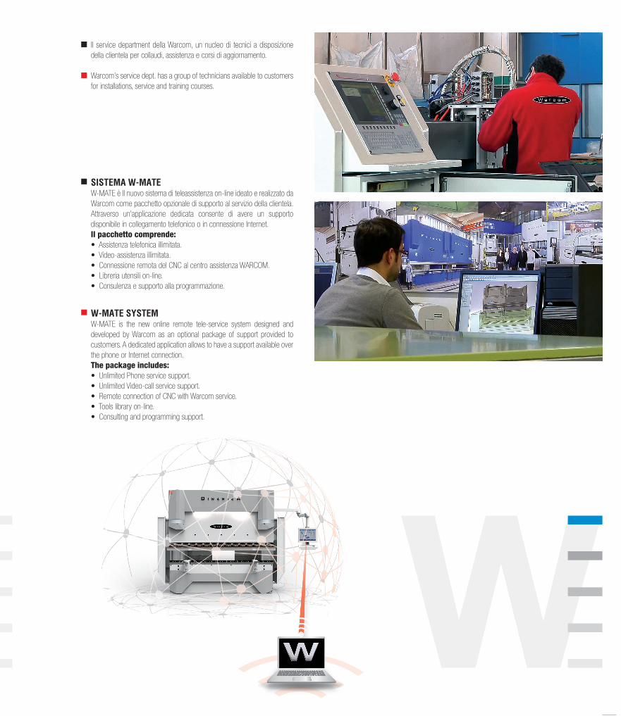
COLLECTION BENDINGCOLLEZIONE PIEGATURA
IIa edi
zion
e
CO
LLEC
TIO
N B
END
ING
COLL
EZIO
NE P
IEGA
TURA