Attrezzi AV™T10, AV™15, AV™30 e AV™50 · Abbassare con cautela la pinza 2 sui componenti...
49
1 Testata di Infalok ® Istruzioni Attrezzi AV™T10, AV™15, AV™30 e AV™50 Norme di sicurezza Questo foglio dati tecnico dovrebbe essere letto prestando particolare attenzione alle norme di sicurezza e istruzioni operative elencate nei manuali di istruzioni AV™10, AV™15, AV™30 e AV™50, da parte di qualsiasi persona che monti o utilizzi le testate Avdelok® e gli attrezzi manuali. Ambito di utilizzo Le testate Lockbolt in combinazione con gli attrezzi AV™10, AV™15, AV™30 e AV™50 sono progettate esclusivamente per la posa dei rivetti strutturali Avdel® Lockbolt Si devono selezionare l’attrezzo di posa e la testata corretti per ogni misura di rivetto, come mostrato nella tabella qui sotto. La qui sotto fornisce un elenco completo dei codici, testate e attrezzi di base necessari per posare ciascuna misura di Lockbolt Questa tabella dovrebbe essere usata per selezionare e ordinare l’attrezzatura di posa corretta. Per le istruzioni di montaggio e manutenzione della testata fare riferimento al numero di pagina provvisto nella tabella. Codici delle testate LOCKBOLT DIMENSIONI TESTATA ATTREZZO DI BASE CODICE PAGINA MODELLO CODICE 3/8" Avdelok ® 73411-03100 2 AVLOCK T10 - 73430-03100 2 AV™10 73430-02000 1/2" Infalok ® 73412-03100 10 AV™30 73434-02000 AVLOCK T30 e T40 - 73432-03200 4 AV™15 73432-02000 73433-03200 6 AV™15 73432-02000 73412-04300 8 HUCK 2620 5/8" Infalok ® 73412-03200 10 AV™30 73434-02000 AVLOCK T30 e T40 - 73412-04400 13 HUCK 2620 e 2628 3/4" Infalok ® 73412-03300 10 AV™30 73434-02000 AVLOCK T30 e T40 - 73412-04500 15 HUCK 2628 7/8" Infalok ® 73410-03200 17 AV™50 73435-02000 AVLOCK T51 - 73455-03100 20 HUCK 506 1" Infalok ® 73410-03100 17 AV™50 73435-02000 AVLOCK T51 - 73454-03100 22 HUCK 507 1 1/8" Infalok ® 73410-03300 17 AV™50 73435-02000 AVLOCK T51 - I M P O R T A N T E Gli attrezzi e le testate devono essere usati in conformità con le norme di sicurezza e istruzioni di montaggio contenute in questo foglio dati e nel manuale di istruzioni dell’attrezzo. La posa di rivetti non inclusi in questo foglio dati potrebbe avere un impatto dannoso sulla durata utile dell’attrezzo e delle testate e potrebbe rendere nulla la garanzia.
Transcript of Attrezzi AV™T10, AV™15, AV™30 e AV™50 · Abbassare con cautela la pinza 2 sui componenti...
1
Testata di Infalok®Istruzioni
Attrezzi AV™T10, AV™15, AV™30 e AV™50
Norme di sicurezza
Questo foglio dati tecnico dovrebbe essere letto prestando particolare attenzione alle norme di sicurezza e istruzioni
operative elencate nei manuali di istruzioni AV™10, AV™15, AV™30 e AV™50, da parte di qualsiasi persona che
monti o utilizzi le testate Avdelok® e gli attrezzi manuali.
Ambito di utilizzo
Le testate Lockbolt in combinazione con gli attrezzi AV™10, AV™15, AV™30 e AV™50 sono progettate esclusivamente
per la posa dei rivetti strutturali Avdel® Lockbolt Si devono selezionare l’attrezzo di posa e la testata corretti per ogni
misura di rivetto, come mostrato nella tabella qui sotto.
La qui sotto fornisce un elenco completo dei codici, testate e attrezzi di base necessari per posare ciascuna misura
di Lockbolt Questa tabella dovrebbe essere usata per selezionare e ordinare l’attrezzatura di posa corretta.
Per le istruzioni di montaggio e manutenzione della testata fare riferimento al numero di pagina provvisto nella tabella.
Codici delle testate
LOCKBOLT
DIMENSIONI
TESTATA ATTREZZO DI BASE
CODICE PAGINA MODELLO CODICE
3/8" Avdelok®
73411-03100 2 AVLOCK T10 -
73430-03100 2 AV™10 73430-02000
1/2" Infalok®
73412-03100 10
AV™30 73434-02000
AVLOCK T30 e T40 -
73432-03200 4 AV™15 73432-02000
73433-03200 6 AV™15 73432-02000
73412-04300 8 HUCK 2620
5/8" Infalok®
73412-03200 10
AV™30 73434-02000
AVLOCK T30 e T40 -
73412-04400 13 HUCK 2620 e 2628
3/4" Infalok®
73412-03300 10
AV™30 73434-02000
AVLOCK T30 e T40 -
73412-04500 15 HUCK 2628
7/8" Infalok®
73410-03200 17
AV™50 73435-02000
AVLOCK T51 -
73455-03100 20 HUCK 506
1" Infalok®
73410-03100 17
AV™50 73435-02000
AVLOCK T51 -
73454-03100 22 HUCK 507
1 1/8" Infalok® 73410-03300 17
AV™50 73435-02000
AVLOCK T51 -
I M P O R T A N T E
Gli attrezzi e le testate devono essere usati in conformità con le norme di sicurezza e istruzioni di montaggio
contenute in questo foglio dati e nel manuale di istruzioni dell’attrezzo. La posa di rivetti non inclusi in questo
foglio dati potrebbe avere un impatto dannoso sulla durata utile dell’attrezzo e delle testate e potrebbe
rendere nulla la garanzia.

2
3
Testata 3/8" Avdelok® 73411-03100 and 73430-03100 for Avlock T10 e
Avdel® AV™10
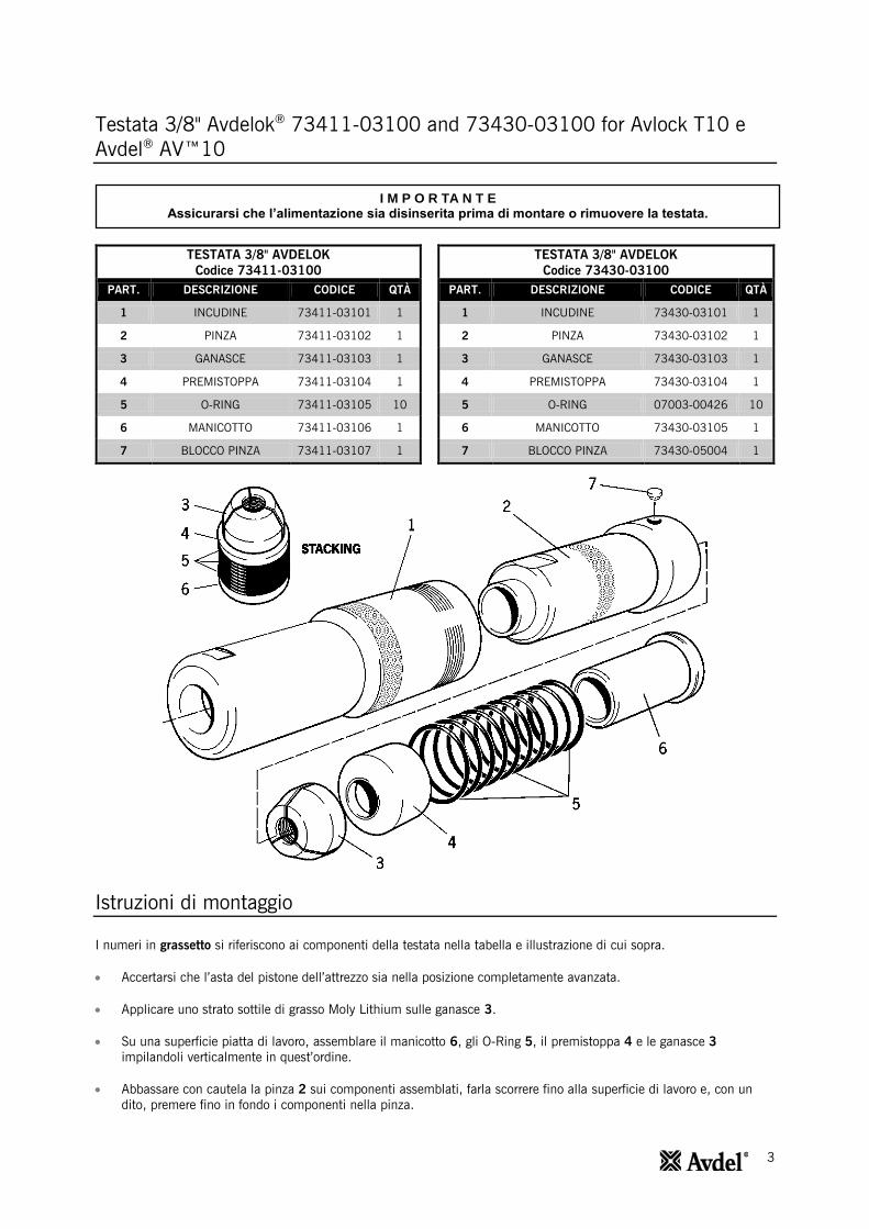
TESTATA 3/8" AVDELOK
Codice 73411-03100
PART. DESCRIZIONE CODICE QTÀ
1 INCUDINE 73411-03101 1
2 PINZA 73411-03102 1
3 GANASCE 73411-03103 1
4 PREMISTOPPA 73411-03104 1
5 O-RING 73411-03105 10
6 MANICOTTO 73411-03106 1
7 BLOCCO PINZA 73411-03107 1
TESTATA 3/8" AVDELOK
Codice 73430-03100
PART. DESCRIZIONE CODICE QTÀ
1 INCUDINE 73430-03101 1
2 PINZA 73430-03102 1
3 GANASCE 73430-03103 1
4 PREMISTOPPA 73430-03104 1
5 O-RING 07003-00426 10
6 MANICOTTO 73430-03105 1
7 BLOCCO PINZA 73430-05004 1
Istruzioni di montaggio
I numeri in grassetto si riferiscono ai componenti della testata nella tabella e illustrazione di cui sopra.
Accertarsi che l’asta del pistone dell’attrezzo sia nella posizione completamente avanzata.
Applicare uno strato sottile di grasso Moly Lithium sulle ganasce 3.
Su una superficie piatta di lavoro, assemblare il manicotto 6, gli O-Ring 5, il premistoppa 4 e le ganasce 3
impilandoli verticalmente in quest’ordine.
Abbassare con cautela la pinza 2 sui componenti assemblati, farla scorrere fino alla superficie di lavoro e, con un
dito, premere fino in fondo i componenti nella pinza.
I M P O R TA N T E Assicurarsi che l’alimentazione sia disinserita prima di montare o rimuovere la testata.
4
Testata 3/8" Avdelok® 73411-03100 and 73430-03100 for Avlock T10 e
Avdel® AV™10
I numeri in grassetto si riferiscono ai componenti della testata nella tabella e illustrazione di pagina 2.
Istruzioni di montaggio
Attrezzo T10 Avlock:
Tenendo l’attrezzo rivolto verso il basso, avvitare la pinza assemblata sull’asta pistone finché non è a filo con
l’estremità dell’adattatore pinza.
Inserire l’inserto di blocco pinza 7 nella pinza 2. Ruotare la pinza 2 sull’asta pistone in qualsiasi direzione finché
l’inserto di blocco pinza 7 si inserisce nella scanalatura più vicina sull’adattatore pinza. L’inserto di blocco pinza 7
dovrebbe essere a filo con la parte esterna della pinza 2.
Far scivolare l’incudine 1 sulla pinza 2 e avvitarla nell’adattatore dell’incudine finché non è salda.
C’è un O-Ring di bloccaggio che crea una certa resistenza per gli ultimi giri del canotto esterno. È assolutamente
necessario che il canotto esterno sia serrato bene contro la faccia posteriore di bloccaggio.
Attrezzo Avdel® AV™10:
La pinza 2 verrà fornita pre-assemblata con estrattore di inserto di blocco pinza 7.
Tenendo dell'utensile rivolto verso il basso, avvitare il assemblato pinza 2 sul pistone fino al inserto di blocco pinza 7
linee con uno dei quattro fori svasati sulla filettatura del pistone. Ruotare due sullo stelo in entrambe le direzioni fino
a inserto di blocco pinza 7 slot nel più vicino foro contatore.
L’inserto di blocco pinza 7 dovrebbe essere a filo con la parte esterna della pinza 2.
Far scivolare l’incudine 1 sulla pinza 2 e avvitarla nell’adattatore dell’incudine finché non è salda.
C’è un O-Ring di bloccaggio che crea una certa resistenza per gli ultimi giri del canotto esterno. È assolutamente
necessario che il canotto esterno sia serrato bene contro la faccia posteriore di bloccaggio.
Istruzioni di manutenzione
Le testate dovrebbero essere sottoposte a manutenzione a intervalli settimanali. Si dovrebbero conservare delle scorte di
tutti i componenti interni di testata dato che vanno sostituiti regolarmente.
Rimuovere le testate eseguendo le ‘Istruzioni di montaggio’ in ordine inverso.
Tutte le parti danneggiate o usurate devono essere sostituite.
Pulire e verificare la condizione di usura delle ganasce 3.
Verificare che il premistoppa 4, il manicotto 6 e gli O-Ring 5 non siano deformati.
Montare seguendo le ‘Istruzioni di montaggio’.
I M P O R TA N T E Assicurarsi che l’alimentazione sia disinserita prima di montare o rimuovere la testata.
5
Testate 1/2" Infalok®
– 73432-03200 per Avdel®
AV™15
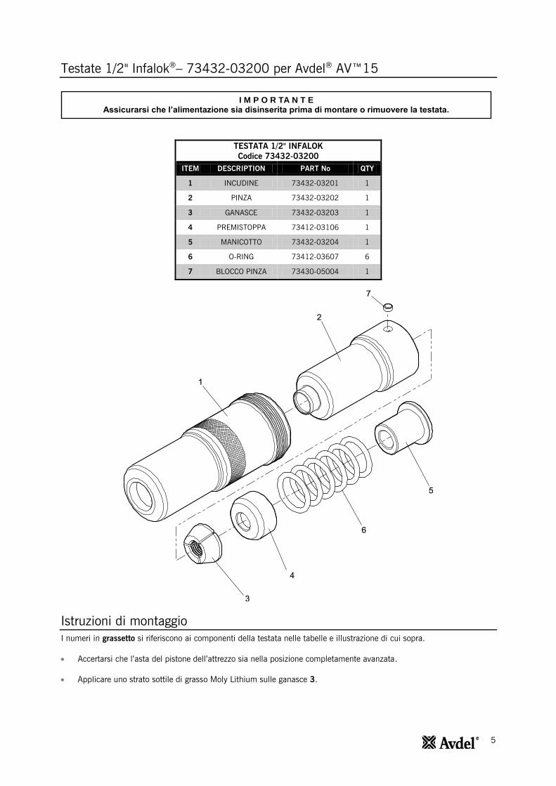
TESTATA 1/2" INFALOK
Codice 73432-03200
ITEM DESCRIPTION PART No QTY
1 INCUDINE 73432-03201 1
2 PINZA 73432-03202 1
3 GANASCE 73432-03203 1
4 PREMISTOPPA 73412-03106 1
5 MANICOTTO 73432-03204 1
6 O-RING 73412-03607 6
7 BLOCCO PINZA 73430-05004 1
Istruzioni di montaggio
I numeri in grassetto si riferiscono ai componenti della testata nelle tabelle e illustrazione di cui sopra.
Accertarsi che l’asta del pistone dell’attrezzo sia nella posizione completamente avanzata.
Applicare uno strato sottile di grasso Moly Lithium sulle ganasce 3.
I M P O R TA N T E Assicurarsi che l’alimentazione sia disinserita prima di montare o rimuovere la testata.
6
Testate1/2" Infalok® – 73432-03200 per Avdel® AV™15
I numeri in grassetto si riferiscono ai componenti della testata nella tabella e illustrazione di pagina 4.
Istruzioni di montaggio
Su una superficie piatta di lavoro, assemblare il manicotto 5, gli O-Ring 6, il premistoppa 4 e le ganasce 3
impilandoli verticalmente in quest’ordine.
Abbassare con cautela la pinza 2 sui componenti assemblati, farla scorrere fino alla superficie di lavoro e, con un
dito, premere fino in fondo i componenti nella pinza.
La pinza 2 verrà fornita pre-assemblata con estrattore di inserto di blocco pinza 7.
Tenendo l’attrezzo rivolto verso il basso, avvitare fino in fondo la pinza 2 assemblata sull’asta pistone finché non è a
filo con l’estremità dell’adattatore pinza.
Inserire l’inserto di blocco pinza 7 nella pinza 2. Ruotare la pinza 2 sull’asta pistone in qualsiasi direzione finché
l’inserto di blocco pinza 7 si inserisce nella scanalatura più vicina sull’adattatore pinza. L’inserto di blocco pinza 7
dovrebbe essere a filo con la parte esterna della pinza 2.
Far scivolare l’incudine 1 sulla pinza 2 e avvitarla nell’adattatore dell’incudine finché non è salda.
C’è un O-Ring di bloccaggio che crea una certa resistenza per gli ultimi giri del canotto esterno. È assolutamente
necessario che il canotto esterno sia serrato bene contro la faccia posteriore di bloccaggio.
Istruzioni di manutenzione
Le testate dovrebbero essere sottoposte a manutenzione a intervalli settimanali. Si dovrebbero conservare delle scorte di
tutti i componenti interni della testata dato che vanno sostituiti regolarmente.
Rimuovere la testata eseguendo le ‘Istruzioni di montaggio’ in ordine inverso.
Tutte le parti danneggiate o usurate devono essere sostituite.
Pulire e verificare la condizione di usura delle ganasce 3.
Verificare che il premistoppa 4, il manicotto 5 e gli O-Ring 6 non siano deformati.
Montare seguendo le ‘Istruzioni di montaggio’.

7
Testate1/2" Infalok®
– 73432-03200 per Avdel® AV™15
TESTATA 1/2" INFALOK
Codice 73433-03200
PART. DESCRIZIONE CODICE QTÀ
1 INCUDINE 73432-03201 1
2 ESTRATTORE 73412-03109 1
3 PINZA 73433-03102 1
4 RILASCIO 73412-03110 1
5 GANASCE 73412-03103 1
6 PREMISTOPPA 73412-03106 1
7 O-RING 73412-03607 6
8 MANICOTTO 73432-03204 1
9 BLOCCO PINZA 73430-05004 1
I M P O R TA N T E Assicurarsi che l’alimentazione sia disinserita prima di montare o rimuovere la testata.
8
Testate1/2" Infalok®– 73432-03200 per Avdel
® AV™15
I numeri in grassetto si riferiscono ai componenti della testata nella tabella e illustrazione di pagina 6.
Istruzioni di montaggio
Accertarsi che l’asta del pistone dell’attrezzo sia nella posizione completamente avanzata.
Applicare uno strato sottile di grasso Moly Lithium sulle ganasce 5.
Su una superficie piatta di lavoro, assemblare il manicotto 8, gli O-Ring 7, il premistoppa 6 e le ganasce 5
impilandoli verticalmente in quest’ordine.
La pinza 3 verrà fornita pre-assemblata con estrattore di ghiere 2 e rilascio della ganascia 4 e con estrattore di
inserto di blocco pinza 9.
Abbassare con cautela la pinza 3 sui componenti assemblati, farla scorrere fino alla superficie di lavoro e, con un
dito, premere fino in fondo i componenti nella pinza.
Tenendo l’attrezzo rivolto verso il basso, avvitare fino in fondo la pinza 3 assemblata sull’asta pistone finché non è a
filo con l’estremità dell’adattatore pinza.
Inserire l’inserto di blocco pinza 9 nella pinza 3. Ruotare la pinza 3 sull’asta pistone in qualsiasi direzione finché
l’inserto di blocco pinza 9 si inserisce nella scanalatura più vicina sull’adattatore pinza. L’inserto di blocco pinza 9
dovrebbe essere a filo con la parte esterna della pinza 3.
Far scivolare l’incudine 1 sulla pinza 3 e avvitarla nell’adattatore dell’incudine finché non è salda.
C’è un O-Ring di bloccaggio che crea una certa resistenza per gli ultimi giri del canotto esterno. È assolutamente
necessario che il canotto esterno sia serrato bene contro la faccia posteriore di bloccaggio.
Si può misurare l’installazione corretta della testata in base al gioco del tubo di fissaggio posteriore di dimensioni
corrette inserito nelle ganasce assemblate della testata.
Istruzioni di manutenzione
Le testate dovrebbero essere sottoposte a manutenzione a intervalli settimanali. Si dovrebbero conservare delle scorte di
tutti i componenti interni della testata dato che vanno sostituiti regolarmente.
Rimuovere la testata eseguendo le ‘Istruzioni di montaggio’ in ordine inverso.
Tutte le parti danneggiate o usurate devono essere sostituite.
Pulire e verificare la condizione di usura delle ganasce 5.
Verificare che l’estrattore di ghiere 2, il premistoppa 6, il manicotto 8 e gli O-Ring 7 non siano deformati.
Per rimuovere un estrattore di ghiere 2 danneggiato o usurato, inserire una punta tra la flangia dell’estrattore e la fine
della pinza 3. L’estrattore di ghiere 2 e il rilascio della ganascia 4 si possono quindi separare e rimuovere dalla pinza
3.
Quando si assemblano un estrattore di ghiere 2 e un rilascio della ganascia 4 nuovi nella pinza 3, per prima cosa ci
sideve assicurare che le filettature siano pulite prima di applicare la Loctite® 243 e avvitare le due parti assieme
nellapinza 3.
Montare seguendo le ‘Istruzioni di montaggio’.
9
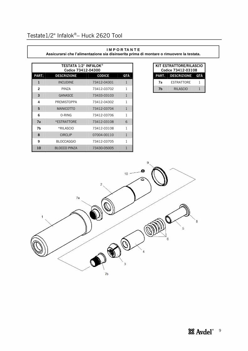
Testate1/2" Infalok®– Huck 2620 Tool
TESTATA 1/2" INFALOK®
Codice 73412-04300
PART. DESCRIZIONE CODICE QTÀ
1 INCUDINE 73412-04301 1
2 PINZA 73412-03702 1
3 GANASCE 73433-03103 1
4 PREMISTOPPA 73412-04302 1
5 MANICOTTO 73412-03704 1
6 O-RING 73412-03706 1
7a *ESTRATTORE 73412-03108 6
7b *RILASCIO 73412-03108 1
8 CIRCLIP 07004-00110 1
9 BLOCCAGGIO 73412-03705 1
10 BLOCCO PINZA 73430-05005 1
KIT ESTRATTORE/RILASCIO
Codice 73412-03108
PART. DESCRIZIONE QTÀ
7a ESTRATTORE 1
7b RILASCIO 1
I M P O R TA N T E Assicurarsi che l’alimentazione sia disinserita prima di montare o rimuovere la testata.
10
Testate1/2" Infalok®– Huck 2620 Tool
I numeri in grassetto si riferiscono ai componenti della testata nella tabella e illustrazione di pagina 8.
Istruzioni di montaggio
Applicare uno strato sottile di grasso Moly Lithium sulle ganasce 3.
Su una superficie piatta di lavoro, assemblare il manicotto 5, gli O-Ring 6, il premistoppa 4 e le ganasce 3
impilandoli verticalmente in quell’ordine.
La pinza 2 verrà fornita pre-assemblata con estrattore di ghiere 7a e rilascio della ganascia 7b.
Collocare la pinza 2 sulla pila assemblata, farla scorrere fino alla superficie di lavoro e, con un dito, premere fino in
fondo la pila nella pinza 2.
Tenendo l’attrezzo rivolto verso il basso, avvitare la pinza assemblata sull’asta piston.
Inserire l'inserto di bloccaggio 10 nella pinza 2. Svitare la pinza 2 fino a che l'inserto di bloccaggio 10 si inserisce
nella scanalatura più vicina sull'asta del pistone. L'inserto di bloccaggio 10 dovrebbe essere a filo con la parte
esterna della pinza 2.
Montare l'incudine 1 e l'inserto di bloccaggio 9 sull'insieme.
Istruzioni di manutenzione
Le testate dovrebbero essere sottoposte a manutenzione a intervalli settimanali. Si dovrebbero conservare delle scorte di
tutti i componenti interni di testata dato che vanno sostituiti regolarmente.
Rimuovere le testate eseguendo le ‘Istruzioni di montaggio’ in ordine inverso.
Tutte le parti danneggiate o usurate devono essere sostituite.
Pulire e verificare la condizione di usura delle ganasce 3.
Verificare che l’estrattore di ghiere 7a, la pinza 2, il manicotto 5 e gli O-Ring 6 non siano deformati.
Per rimuovere un estrattore di ghiere 7a danneggiato o usurato, estrattore di ghiere 7a il più possibile dalla pinza 2.
Inserire il rilascio della ganascia 7b tra la flangia dell’estrattore di ghiere 7a e la parte anteriore della pinza 2. Girare
la pinza 2 e spingere fuori i resti del rilascio della ganascia 7b.
Quando si assemblano un estrattore di ghiere 7a e un rilascio della ganascia 7b nuovi nella pinza 2, per prima cosa
ci si deve assicurare che le filettature siano pulite prima di applicare la Loctite® 243 e avvitare le due parti assieme
nella pinza 2.
Montare seguendo le ‘Istruzioni di montaggio’.
11
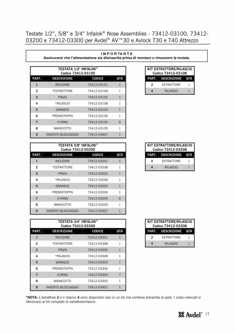
Testate 1/2”, 5/8” e 3/4” Infalok® Nose Assemblies - 73412-03100, 73412-
03200 e 73412-03300 per Avdel® AV™30 e Avlock T30 e T40 Attrezzo
TESTATA 1/2" INFALOK®
Codice 73412-03100
PART. DESCRIZIONE CODICE QTÀ
1 INCUDINE 73412-03101 1
2 *ESTRATTORE 73412-03108 1
3 PINZA 73412-03102 1
4 *RILASCIO 73412-03108 1
5 GANASCE 73412-03103 1
6 PREMISTOPPA 73412-03106 1
7 O-RING 73412-03104 6
8 MANICOTTO 73412-03105 1
9 INSERTO BLOCCAGGIO 73412-03407 1
KIT ESTRATTORE/RILASCIO
Codice 73412-03108
PART. DESCRIZIONE QTÀ
2 ESTRATTORE 1
4 RILASCIO 1
TESTATA 5/8" INFALOK®
Codice 73412-03200
PART. DESCRIZIONE CODICE QTÀ
1 INCUDINE 73412-03201 1
2 *ESTRATTORE 73412-03208 1
3 PINZA 73412-03202 1
4 *RILASCIO 73412-03208 1
5 GANASCE 73412-03203 1
6 PREMISTOPPA 73412-03206 1
7 O-RING 73412-03204 6
8 MANICOTTO 73412-03205 1
9 INSERTO BLOCCAGGIO 73412-03407 1
KIT ESTRATTORE/RILASCIO
Codice 73412-03208
PART. DESCRIZIONE QTÀ
2 ESTRATTORE 1
4 RILASCIO 1
TESTATA 3/4" INFALOK®
Codice 73412-03300
PART. DESCRIZIONE CODICE QTÀ
1 INCUDINE 73412-03301 1
2 *ESTRATTORE 73412-03308 1
3 PINZA 73412-03302 1
4 *RILASCIO 73412-03308 1
5 GANASCE 73412-03303 1
6 PREMISTOPPA 73412-03306 1
7 O-RING 73412-03304 7
8 MANICOTTO 73412-03305 1
9 INSERTO BLOCCAGGIO 73412-03407 1
KIT ESTRATTORE/RILASCIO
Codice 73412-03308
PART. DESCRIZIONE QTÀ
2 ESTRATTORE 1
4 RILASCIO 1
*NOTA: L’estrattore 2 e il rilascio 4 sono disponibili solo in un kit che contiene entrambe le parti. I codici elencati si
riferiscono al kit completo di estrattore/rilascio.
I M P O R TA N T E Assicurarsi che l’alimentazione sia disinserita prima di montare o rimuovere la testata.
12
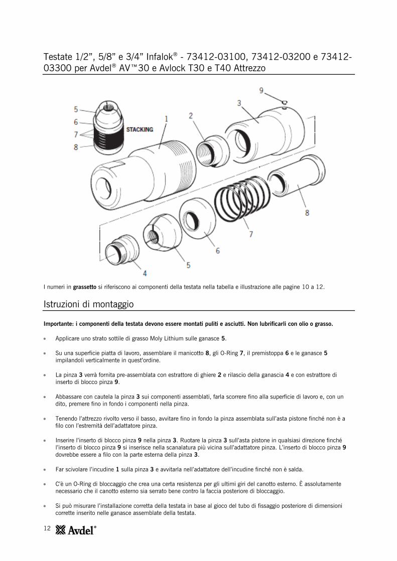
Testate 1/2”, 5/8” e 3/4” Infalok® - 73412-03100, 73412-03200 e 73412-
03300 per Avdel® AV™30 e Avlock T30 e T40 Attrezzo
I numeri in grassetto si riferiscono ai componenti della testata nella tabella e illustrazione alle pagine 10 a 12.
Istruzioni di montaggio
Importante: i componenti della testata devono essere montati puliti e asciutti. Non lubrificarli con olio o grasso.
Applicare uno strato sottile di grasso Moly Lithium sulle ganasce 5.
Su una superficie piatta di lavoro, assemblare il manicotto 8, gli O-Ring 7, il premistoppa 6 e le ganasce 5
impilandoli verticalmente in quest’ordine.
La pinza 3 verrà fornita pre-assemblata con estrattore di ghiere 2 e rilascio della ganascia 4 e con estrattore di
inserto di blocco pinza 9.
Abbassare con cautela la pinza 3 sui componenti assemblati, farla scorrere fino alla superficie di lavoro e, con un
dito, premere fino in fondo i componenti nella pinza.
Tenendo l’attrezzo rivolto verso il basso, avvitare fino in fondo la pinza assemblata sull’asta pistone finché non è a
filo con l’estremità dell’adattatore pinza.
Inserire l’inserto di blocco pinza 9 nella pinza 3. Ruotare la pinza 3 sull’asta pistone in qualsiasi direzione finché
l’inserto di blocco pinza 9 si inserisce nella scanalatura più vicina sull’adattatore pinza. L’inserto di blocco pinza 9
dovrebbe essere a filo con la parte esterna della pinza 3.
Far scivolare l’incudine 1 sulla pinza 3 e avvitarla nell’adattatore dell’incudine finché non è salda.
C’è un O-Ring di bloccaggio che crea una certa resistenza per gli ultimi giri del canotto esterno. È assolutamente
necessario che il canotto esterno sia serrato bene contro la faccia posteriore di bloccaggio.
Si può misurare l’installazione corretta della testata in base al gioco del tubo di fissaggio posteriore di dimensioni
corrette inserito nelle ganasce assemblate della testata.

13
Testate 1/2”, 5/8” e 3/4” Infalok® - 73412-03100, 73412-03200 e
73412-03300 per Avdel® AV™30 e Avlock T30 e T40 Attrezzo
Istruzioni di manutenzione
Le testate dovrebbero essere sottoposte a manutenzione a intervalli settimanali. Si dovrebbero conservare delle scorte di
tutti i componenti interni della testata dato che vanno sostituiti regolarmente.
Rimuovere la testata eseguendo le ‘Istruzioni di montaggio’ in ordine inverso.
Tutte le parti danneggiate o usurate devono essere sostituite.
Pulire e verificare la condizione di usura delle ganasce 5.
Verificare che l’estrattore di ghiere 2, il premistoppa 6, il manicotto 8 e gli O-Ring 7 non siano deformati.
Per rimuovere un estrattore di ghiere 2 danneggiato o usurato, inserire una punta tra la flangia dell’estrattore e la fine
della pinza 3. L’estrattore di ghiere 2 e il rilascio della ganascia 4 si possono quindi separare e rimuovere dalla pinza
3.
Quando si assemblano un estrattore di ghiere 2 e un rilascio della ganascia 4 nuovi nella pinza 3, per prima cosa ci
sideve assicurare che le filettature siano pulite prima di applicare la Loctite® 243 e avvitare le due parti assieme
nellapinza 3.
Montare seguendo le ‘Istruzioni di montaggio’.
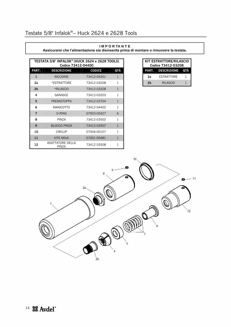
14
Testate 5/8" Infalok®– Huck 2624 e 2628 Tools
TESTATA 5/8" INFALOK®
(HUCK 2624 e 2628 TOOLS)
Codice 73412-04400
PART. DESCRIZIONE CODICE QTÀ
1 INCUDINE 73412-04301 1
2a *ESTRATTORE 73412-03208 1
2b *RILASCIO 73412-03208 1
4 GANASCE 73412-03203 1
5 PREMISTOPPA 73412-03704 1
6 MANICOTTO 73412-04402 1
7 O-RING 07003-00427 6
8 PINZA 73412-03502 1
9 BLOCCO PINZA 73412-03507 1
10 CIRCLIP 07004-00107 1
11 VITE M5x5 07001-00481 1
12 ADATTATORE DELLA
PINZA 73412 03508 1
KIT ESTRATTORE/RILASCIO
Codice 73412-03208
PART. DESCRIZIONE QTÀ
2a ESTRATTORE 1
2b RILASCIO 1
I M P O R TA N T E Assicurarsi che l’alimentazione sia disinserita prima di montare o rimuovere la testata.
15
Testate 5/8" Infalok®– Huck 2624 e 2628 Tools
I numeri in grassetto si riferiscono ai componenti della testata nella tabella e illustrazione alle pagina 13.
Istruzioni di montaggio
I numeri in grassetto si riferiscono ai componenti della testata nelle tabelle e illustrazione di cui sopra.
Applicare uno strato sottile di grasso Moly Lithium sulle ganasce 4.
Su una superficie piatta di lavoro, assemblare il manicotto 6, gli O-Ring 7, il premistoppa 5 e le ganasce 4
impilandoli verticalmente in quell’ordine.
La pinza 8 verrà fornita pre-assemblata con estrattore di ghiere 2a e rilascio della ganascia 2b.
Collocare la pinza 8 sulla pila assemblata, farla scorrere fino alla superficie di lavoro e, con un dito, premere fino in
fondo la pila nella pinza 8.
Avvitare completamente l'adattatore della pinza 12 nel corpo della pinza. La spalla dell'adattatore della pinza 12
dovrebbe essere in contatto con la parte posteriore della pinza 8.
Inserire l'inserto di blocco piza 9 nella pinza 8. Svitare la pinza 8 fino a che l'inserto di blocco pinza 9 si inserisce
nella scanalatura più vicina sull'asta del pistone. L'inserto di blocco pinza 9 dovrebbe essere a filo con la parte
esterna della pinza 8
Istruzioni di manutenzione
Le testate dovrebbero essere sottoposte a manutenzione a intervalli settimanali. Si dovrebbero conservare delle scorte di
tutti i componenti interni di testata dato che vanno sostituiti regolarmente.
Rimuovere le testate eseguendo le ‘Istruzioni di montaggio’ in ordine inverso.
Tutte le parti danneggiate o usurate devono essere sostituite.
Pulire e verificare la condizione di usura delle ganasce 4.
Verificare che l’estrattore di ghiere 2a, il premistoppa 5, il manicotto 6 e gli O-Ring 7 non siano deformati.
Per rimuovere un estrattore di ghiere 2a danneggiato o usurato, estrattore di ghiere 2a il più possibile dalla pinza 8.
Inserire il rilascio della ganascia 2b tra la flangia dell’estrattore di ghiere 2a e la parte anteriore della pinza 8. Girare
la pinza 8 e spingere fuori i resti del rilascio della ganascia 2b.
Quando si assemblano un estrattore di ghiere 2a e un rilascio della ganascia 2b nuovi nella pinza 8, per prima cosa
ci si deve assicurare che le filettature siano pulite prima di applicare la Loctite® 243 e avvitare le due parti assieme
nella pinza 8.
Montare seguendo le ‘Istruzioni di montaggio’.
16
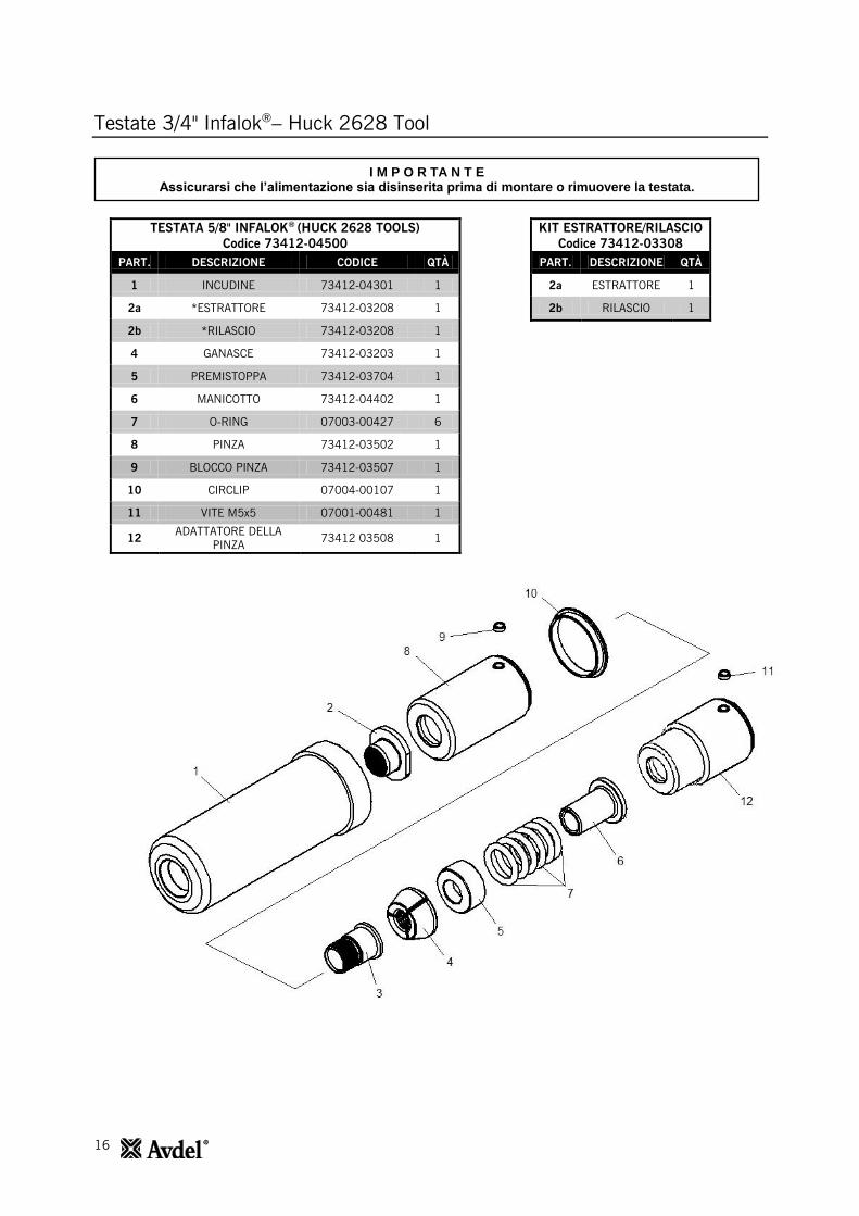
Testate 3/4" Infalok®– Huck 2628 Tool
TESTATA 5/8" INFALOK®
(HUCK 2628 TOOLS)
Codice 73412-04500
PART. DESCRIZIONE CODICE QTÀ
1 INCUDINE 73412-04301 1
2a *ESTRATTORE 73412-03208 1
2b *RILASCIO 73412-03208 1
4 GANASCE 73412-03203 1
5 PREMISTOPPA 73412-03704 1
6 MANICOTTO 73412-04402 1
7 O-RING 07003-00427 6
8 PINZA 73412-03502 1
9 BLOCCO PINZA 73412-03507 1
10 CIRCLIP 07004-00107 1
11 VITE M5x5 07001-00481 1
12 ADATTATORE DELLA
PINZA 73412 03508 1
KIT ESTRATTORE/RILASCIO
Codice 73412-03308
PART. DESCRIZIONE QTÀ
2a ESTRATTORE 1
2b RILASCIO 1
I M P O R TA N T E Assicurarsi che l’alimentazione sia disinserita prima di montare o rimuovere la testata.

17
Testate 3/4" Infalok®– Huck 2628 Tool
I numeri in grassetto si riferiscono ai componenti della testata nella tabella e illustrazione alle pagina 15.
Istruzioni di montaggio
Applicare uno strato sottile di grasso Moly Lithium sulle ganasce 4.
Su una superficie piatta di lavoro, assemblare il manicotto 6, gli O-Ring 7, il premistoppa 5 e le ganasce 4
impilandoli verticalmente in quell’ordine.
La pinza 8 verrà fornita pre-assemblata con estrattore di ghiere 2 e rilascio della ganascia 3, come illustrato.
Collocare la pinza 8 sulla pila assemblata, farla scorrere fino alla superficie di lavoro e, con un dito, premere fino in
fondo la pila nella pinza 8.
Avvitare completamente l'adattatore della pinza 12 nel corpo della pinza. La spalla dell'adattatore della pinza 12
dovrebbe essere in contatto con la parte posteriore della pinza 8.
Inserire l'inserto di blocco pinza 9 nella pinza 8. Svitare l'adattatore della pinza 12 fino a che l'inserto di blocco pinza
9 si inserisce nella scanalatura più vicina sull'asta del pistone. L'inserto di blocco pinza 9 dovrebbe essere a filo con
la parte esterna della pinza 8.
Istruzioni di manutenzione
Le testate dovrebbero essere sottoposte a manutenzione a intervalli settimanali. Si dovrebbero conservare delle scorte di
tutti i componenti interni di testata dato che vanno sostituiti regolarmente.
Rimuovere le testate eseguendo le ‘Istruzioni di montaggio’ in ordine inverso.
Tutte le parti danneggiate o usurate devono essere sostituite.
Pulire e verificare la condizione di usura delle ganasce 4.
Verificare che l’estrattore di ghiere 2, il premistoppa 5, il manicotto 6 e gli O-Ring 7 non siano deformati.
Per rimuovere un estrattore di ghiere 2 danneggiato o usurato, estrattore di ghiere 2 il più possibile dalla pinza 8.
Inserire il rilascio della ganascia 3 tra la flangia dell’estrattore di ghiere 8 e la parte anteriore della pinza 2. Girare la
pinza 2 e spingere fuori i resti del rilascio della ganascia 3.
Quando si assemblano un estrattore di ghiere 2 e un rilascio della ganascia 3 nuovi nella pinza 8, per prima cosa ci
si deve assicurare che le filettature siano pulite prima di applicare la Loctite® 243 e avvitare le due parti assieme
nella pinza 8.
Montare seguendo le ‘Istruzioni di montaggio’.
18
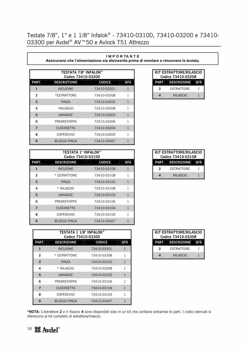
Testate 7/8”, 1” e 1 1/8” Infalok® - 73410-03100, 73410-03200 e 73410-
03300 per Avdel® AV™50 e Avlock T51 Attrezzo
TESTATA 7/8" INFALOK®
Codice 73410-03200
PART. DESCRIZTIONE CODICE QTÀ
1 INCUDINE 73410-03201 1
2 *ESTRATTORE 73410-03208 1
3 PINZA 73410-03202 1
4 *RILASCIO 73410-03208 1
5 GANASCE 73410-03203 1
6 PREMISTOPPA 73410-03206 1
7 CUSCINETTO 73410-03204 1
8 COPERCHIO 73410-03205 1
9 BLOCCO PINZA 73412-03407 1
KIT ESTRATTORE/RILASCIO
Codice 73410-03208
PART. DESCRIZIONE QTÀ
2 ESTRATTORE 1
4 RILASCIO 1
TESTATA 1" INFALOK®
Codice 73410-03100
PART. DESCRIZIONE CODICE QTÀ
1 INCUDINE 73410-03109 1
2 * ESTRATTORE 73410-03108 1
3 PINZA 73410-03102 1
4 * RILASCIO 73410-03108 1
5 GANASCE 73410-03103 1
6 PREMISTOPPA 73410-03106 1
7 CUSCINETTO 73410-03104 1
8 COPERCHIO 73410-03105 1
9 BLOCCO PINZA 73412-03407 1
KIT ESTRATTORE/RILASCIO
Codice 73410-03108
PART. DESCRIZIONE QTÀ
2 ESTRATTORE 1
4 RILASCIO 1
TESTATA 1 1/8" INFALOK®
Codice 73410-03300
PART. DESCRIZIONE CODICE QTÀ
1 INCUDINE 73410-03301 1
2 * ESTRATTORE 73410-03308 1
3 PINZA 73410-03102 1
4 * RILASCIO 73410-03308 1
5 GANASCE 73410-03103 1
6 PREMISTOPPA 73410-03106 1
7 CUSCINETTO 73410-03104 1
8 COPERCHIO 73410-03105 1
9 BLOCCO PINZA 73412-03407 1
KIT ESTRATTORE/RILASCIO
Codice 73410-03308
PART. DESCRIZIONE QTÀ
2 ESTRATTORE 1
4 RILASCIO 1
*NOTA: L’estrattore 2 e il rilascio 4 sono disponibili solo in un kit che contiene entrambe le parti. I codici elencati si
riferiscono al kit completo di estrattore/rilascio.
I M P O R TA N T E Assicurarsi che l’alimentazione sia disinserita prima di montare o rimuovere la testata.
19
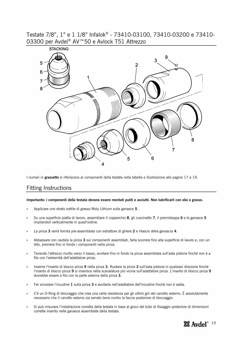
Testate 7/8”, 1” e 1 1/8” Infalok® - 73410-03100, 73410-03200 e 73410-
03300 per Avdel® AV™50 e Avlock T51 Attrezzo
I numeri in grassetto si riferiscono ai componenti della testata nella tabella e illustrazione alle pagine 17 a 19.
Fitting Instructions
Importante: i componenti della testata devono essere montati puliti e asciutti. Non lubrificarli con olio o grasso.
Applicare uno strato sottile di grasso Moly Lithium sulle ganasce 5.
Su una superficie piatta di lavoro, assemblare il copperchio 8, gli cuscinetto 7, il premistoppa 6 e le ganasce 5
impilandoli verticalmente in quest’ordine.
La pinza 3 verrà fornita pre-assemblata con estrattore di ghiere 2 e rilascio della ganascia 4.
Abbassare con cautela la pinza 3 sui componenti assemblati, farla scorrere fino alla superficie di lavoro e, con un
dito, premere fino in fondo i componenti nella pinza.
Tenendo l’attrezzo rivolto verso il basso, avvitare fino in fondo la pinza assemblata sull’asta pistone finché non è a
filo con l’estremità dell’adattatore pinza.
Inserire l’inserto di blocco pinza 9 nella pinza 3. Ruotare la pinza 3 sull’asta pistone in qualsiasi direzione finché
l’inserto di blocco pinza 9 si inserisce nella scanalatura più vicina sull’adattatore pinza. L’inserto di blocco pinza 9
dovrebbe essere a filo con la parte esterna della pinza 3.
Far scivolare l’incudine 1 sulla pinza 3 e avvitarla nell’adattatore dell’incudine finché non è salda.
C’è un O-Ring di bloccaggio che crea una certa resistenza per gli ultimi giri del canotto esterno. È assolutamente
necessario che il canotto esterno sia serrato bene contro la faccia posteriore di bloccaggio.
Si può misurare l’installazione corretta della testata in base al gioco del tubo di fissaggio posteriore di dimensioni
corrette inserito nelle ganasce assemblate della testata.
20
Testate 7/8”, 1” e 1 1/8” Infalok® - 73410-03100, 73410-03200 e
73410-03300 per Avdel® AV™50 e Avlock T51 Attrezzo
Istruzioni di manutenzione
Le testate dovrebbero essere sottoposte a manutenzione a intervalli settimanali. Si dovrebbero conservare delle scorte di
tutti i componenti interni della testata dato che vanno sostituiti regolarmente.
Rimuovere la testata eseguendo le ‘Istruzioni di montaggio’ in ordine inverso.
Tutte le parti danneggiate o usurate devono essere sostituite.
Pulire e verificare la condizione di usura delle ganasce 5.
Verificare che l’estrattore di ghiere 2, il premistoppa 6, il copperchio 8 e gli cuscinetto 7 non siano deformati.
Per rimuovere un estrattore di ghiere 2 danneggiato o usurato, inserire una punta tra la flangia dell’estrattore e la fine
della pinza 3. L’estrattore di ghiere 2 e il rilascio della ganascia 4 si possono quindi separare e rimuovere dalla pinza
3.
Quando si assemblano un estrattore di ghiere 2 e un rilascio della ganascia 4 nuovi nella pinza 3, per prima cosa ci
sideve assicurare che le filettature siano pulite prima di applicare la Loctite® 243 e avvitare le due parti assieme
nellapinza 3.
Montare seguendo le ‘Istruzioni di montaggio’.
21
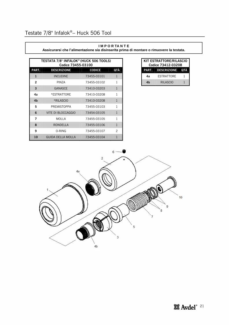
Testate 7/8" Infalok®– Huck 506 Tool
TESTATA 7/8" INFALOK®
(HUCK 506 TOOLS)
Codice 73455-03100
PART. DESCRIZIONE CODICE QTÀ
1 INCUDINE 73455-03101 1
2 PINZA 73455-03102 1
3 GANASCE 73410-03203 1
4a *ESTRATTORE 73410-03208 1
4b *RILASCIO 73410-03208 1
5 PREMISTOPPA 73455-03103 1
6 VITE DI BLOCCAGGIO 73454-03105 1
7 MOLLA 73455-03105 1
8 RONDELLA 73455-03106 1
9 O-RING 73455-03107 2
10 GUIDA DELLA MOLLA 73455-03104 1
KIT ESTRATTORE/RILASCIO
Codice 73412-03208
PART. DESCRIZIONE QTÀ
4a ESTRATTORE 1
4b RILASCIO 1
I M P O R TA N T E Assicurarsi che l’alimentazione sia disinserita prima di montare o rimuovere la testata.
22
Testate 7/8" Infalok®– Huck 506 Tool
I numeri in grassetto si riferiscono ai componenti della testata nella tabella e illustrazione alle pagina 20.
Istruzioni di montaggio
Applicare uno strato sottile di grasso Moly Lithium sulle ganasce 4.
Assemblare il guida della molla 10, gli O-Ring 9, il rondella 8 e le molla 7.
La pinza 2 verrà fornita pre-assemblata con estrattore di ghiere 4a e rilascio della ganascia 4b, come illustrato.
Collocare la pinza 2 sulla pila assemblata, farla scorrere fino alla superficie di lavoro e, con un dito, premere fino in
fondo la pila nella pinza 2.
Avvitare completamente la pinza 2 e il gruppo assemblato sull'adattatore della pinza dell'attrezzo (montato
sull'attrezzo).
Inserire la vite di bloccaggio 6 nella pinza 2. Svitare la pinza 2 fino a riuscire a stringere la vite di bloccaggio 6 nella
scanalatura più vicina sull'adattatore della pinza dell'attrezzo. Una volta assemblata, la vite di bloccaggio 6 dovrebbe
essere a filo con la parte esterna della pinza 2.
Istruzioni di manutenzione
Le testate dovrebbero essere sottoposte a manutenzione a intervalli settimanali. Si dovrebbero conservare delle scorte di
tutti i componenti interni di testata dato che vanno sostituiti regolarmente.
Rimuovere le testate eseguendo le ‘Istruzioni di montaggio’ in ordine inverso.
Tutte le parti danneggiate o usurate devono essere sostituite.
Pulire e verificare la condizione di usura delle ganasce 3.
Verificare che l’estrattore di ghiere 4a, la premistoppa 5, il guida della molla 10 e gli O-Ring 9 non siano deformati.
Per rimuovere un estrattore di ghiere 4a danneggiato o usurato, estrattore di ghiere 4a il più possibile dalla pinza 2.
Inserire il rilascio della ganascia 4b tra la flangia dell’estrattore di ghiere 4a e la parte anteriore della pinza 2. Girare
la pinza 2 e spingere fuori i resti del rilascio della ganascia 4b.
Quando si assemblano un estrattore di ghiere 4a e un rilascio della ganascia 4b nuovi nella pinza 2, per prima cosa
ci si deve assicurare che le filettature siano pulite prima di applicare la Loctite® 243 e avvitare le due parti assieme
nella pinza 2.
Montare seguendo le ‘Istruzioni di montaggio’.

23
Testate 1" Infalok®– Huck 507 Tool
TESTATA 1" INFALOK®
(HUCK 507 TOOLS)
Codice 73454-03100
PART. DESCRIZIONE CODICE QTÀ
1 INCUDINE 73451-03101 1
2 PINZA 73454-03102 1
3a *ESTRATTORE 73410-03108 1
3b *RILASCIO 73410-03108 1
4 GANASCE 73410-03103 1
5 PREMISTOPPA 73454-03103 1
6 GUIDA DELLA MOLLA 73454-03104 1
7 VITE M6 73454-03105 1
8 O-RING 07003-00013 11
KIT ESTRATTORE/RILASCIO
Codice 73411-03208
PART. DESCRIZIONE QTÀ
3a ESTRATTORE 1
3b RILASCIO 1
I M P O R TA N T E Assicurarsi che l’alimentazione sia disinserita prima di montare o rimuovere la testata.
24
Testate 1" Infalok®– Huck 507 Tool
I numeri in grassetto si riferiscono ai componenti della testata nella tabella e illustrazione alle pagina 22.
Istruzioni di montaggio
Applicare uno strato sottile di grasso Moly Lithium sulle ganasce 4.
Assemblare il guida della molla 6, gli O-Ring 8, il premistoppa 5 e le ganasce 4.
La pinza 2 verrà fornita pre-assemblata con estrattore di ghiere 3a e rilascio della ganascia 3b.
Mettere pinza 2 sopra la pila assemblata, spingere completamente lo stack all'interno pinza 2.
Vite pinzat 2 e lo stack assemblato completamente sul Strumento pistone pinza adattatore (montato sullo
strumento).
Inserire la vite 7 nella pinza 2. Svitare la pinza 2 fino a riuscire a stringere la vite 7 nella scanalatura più vicina
sull'adattatore della pinza dell'attrezzo. Una volta assemblata, la vite 7 dovrebbe essere a filo con la parte esterna
della pinza 2.
Istruzioni di manutenzione
Le testate dovrebbero essere sottoposte a manutenzione a intervalli settimanali. Si dovrebbero conservare delle scorte di
tutti i componenti interni di testata dato che vanno sostituiti regolarmente.
Rimuovere le testate eseguendo le ‘Istruzioni di montaggio’ in ordine inverso.
Tutte le parti danneggiate o usurate devono essere sostituite.
Pulire e verificare la condizione di usura delle ganasce 4.
Verificare che l’estrattore di ghiere 3a, la premistoppa 5, il guida della molla 6 e gli O-Ring 8 non siano deformati.
Per rimuovere un estrattore di ghiere 3a danneggiato o usurato, estrattore di ghiere 3a il più possibile dalla pinza 2.
Inserire il rilascio della ganascia 3b tra la flangia dell’estrattore di ghiere 3a e la parte anteriore della pinza 2. Girare
la pinza 2 e spingere fuori i resti del rilascio della ganascia 3b.
Quando si assemblano un estrattore di ghiere 3a e un rilascio della ganascia 3b nuovi nella pinza 2, per prima cosa
ci si deve assicurare che le filettature siano pulite prima di applicare la Loctite® 243 e avvitare le due parti assieme
nella pinza 2.
Montare seguendo le ‘Istruzioni di montaggio’.

25
Holding your world together®
Su www.StanleyEngineeredFastening.com/contact, è possibile trovare la sede di STANLEY Engineered Fastening più vicina
Per il distributore autorizzato più vicino, consultare www.StanleyEngineeredFastening.com/econtact/distributors
Numero del manuale Versione C/N
07900-00919 C 14/071
www.StanleyEngineeredFastening.com
© 2013 Stanley Black & Decker, Inc., Rev. 01.2014
Avdel UK Limited Pacific House, 2 Swiftfields
Welwyn Garden City, Hertfordshire AL7 1LY Tel. +44 (0)1707 292-000 · Fax -199
Avbolt®, Avdel®, Avdelok®, Avex®, Avinox®, Avseal®, Avtainer®, Hemlok®, Maxlok® e Monobolt® sono marchi commerciali di Avdel UK Limited. I nomi e i logo delle altre società qui menzionate sono marchi commerciali dei rispettivi proprietari. I dati riportati sono soggetti a modifiche senza preavviso, in linea con la politica di sviluppo e miglioramento continuo dei prodotti adottata dall’azienda. L’agente Avdel di zona è a disposizione dei clienti, qualora vi fosse la necessità di informazioni aggiornate.
1
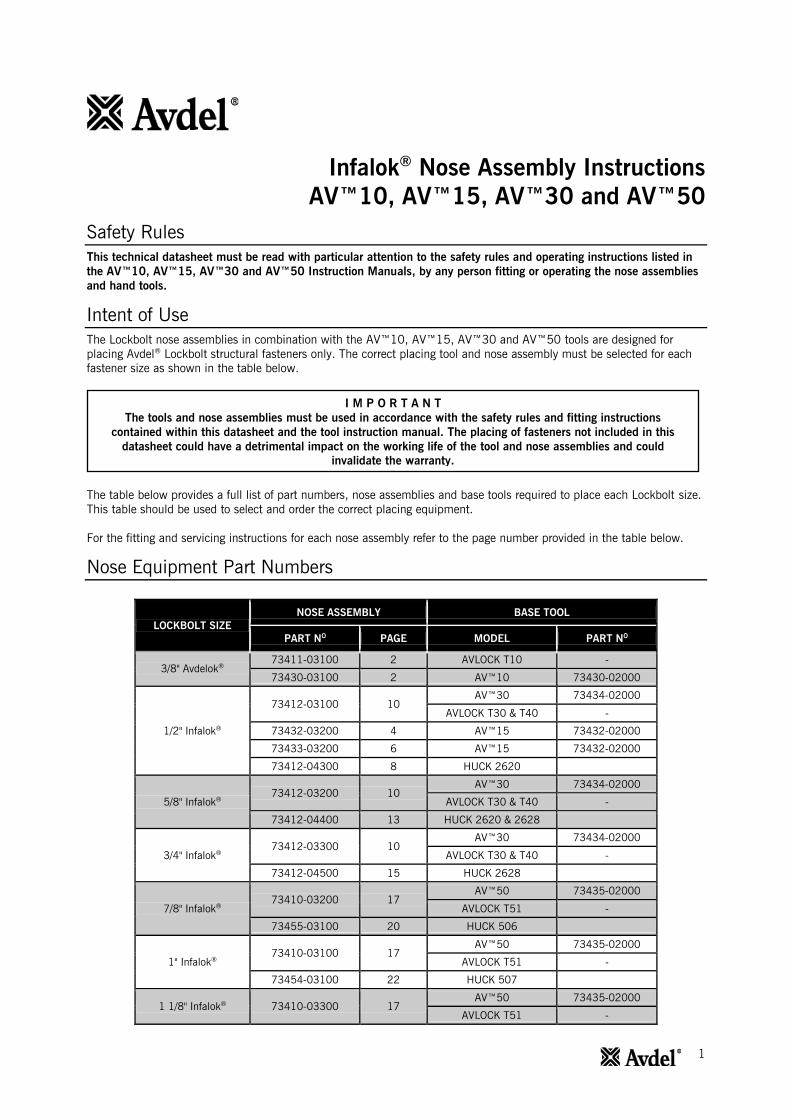
Infalok® Nose Assembly Instructions
AV™10, AV™15, AV™30 and AV™50
Safety Rules
This technical datasheet must be read with particular attention to the safety rules and operating instructions listed in
the AV™10, AV™15, AV™30 and AV™50 Instruction Manuals, by any person fitting or operating the nose assemblies
and hand tools.
Intent of Use
The Lockbolt nose assemblies in combination with the AV™10, AV™15, AV™30 and AV™50 tools are designed for
placing Avdel® Lockbolt structural fasteners only. The correct placing tool and nose assembly must be selected for each
fastener size as shown in the table below.
The table below provides a full list of part numbers, nose assemblies and base tools required to place each Lockbolt size.
This table should be used to select and order the correct placing equipment.
For the fitting and servicing instructions for each nose assembly refer to the page number provided in the table below.
Nose Equipment Part Numbers
LOCKBOLT SIZE
NOSE ASSEMBLY BASE TOOL
PART NO PAGE MODEL PART N
O
3/8" Avdelok®
73411-03100 2 AVLOCK T10 -
73430-03100 2 AV™10 73430-02000
1/2" Infalok®
73412-03100 10
AV™30 73434-02000
AVLOCK T30 & T40 -
73432-03200 4 AV™15 73432-02000
73433-03200 6 AV™15 73432-02000
73412-04300 8 HUCK 2620
5/8" Infalok®
73412-03200 10
AV™30 73434-02000
AVLOCK T30 & T40 -
73412-04400 13 HUCK 2620 & 2628
3/4" Infalok®
73412-03300 10
AV™30 73434-02000
AVLOCK T30 & T40 -
73412-04500 15 HUCK 2628
7/8" Infalok®
73410-03200 17
AV™50 73435-02000
AVLOCK T51 -
73455-03100 20 HUCK 506
1" Infalok®
73410-03100 17
AV™50 73435-02000
AVLOCK T51 -
73454-03100 22 HUCK 507
1 1/8" Infalok® 73410-03300 17
AV™50 73435-02000
AVLOCK T51 -
I M P O R T A N T
The tools and nose assemblies must be used in accordance with the safety rules and fitting instructions
contained within this datasheet and the tool instruction manual. The placing of fasteners not included in this
datasheet could have a detrimental impact on the working life of the tool and nose assemblies and could
invalidate the warranty.
2
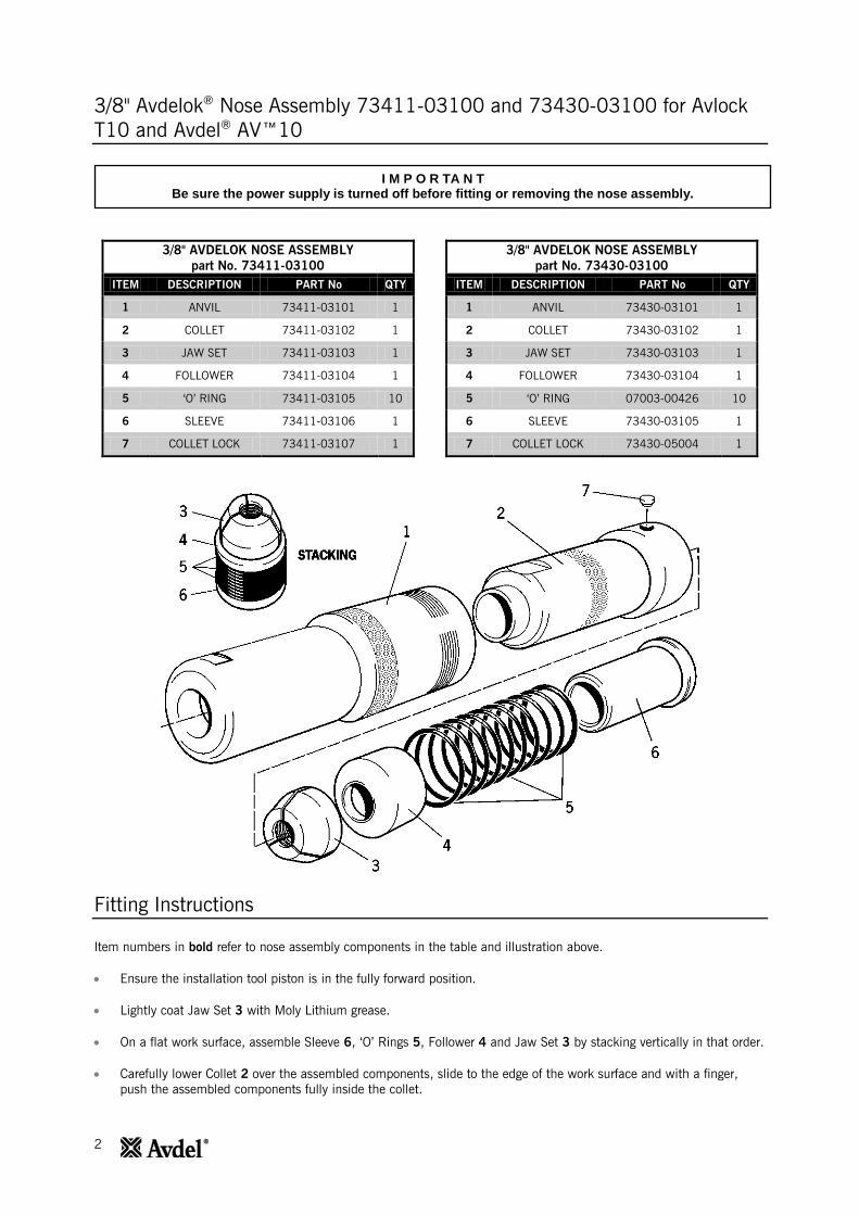
3/8" Avdelok®
Nose Assembly 73411-03100 and 73430-03100 for Avlock
T10 and Avdel® AV™10
3/8" AVDELOK NOSE ASSEMBLY
part No. 73411-03100
ITEM DESCRIPTION PART No QTY
1 ANVIL 73411-03101 1
2 COLLET 73411-03102 1
3 JAW SET 73411-03103 1
4 FOLLOWER 73411-03104 1
5 ‘O’ RING 73411-03105 10
6 SLEEVE 73411-03106 1
7 COLLET LOCK 73411-03107 1
3/8" AVDELOK NOSE ASSEMBLY
part No. 73430-03100
ITEM DESCRIPTION PART No QTY
1 ANVIL 73430-03101 1
2 COLLET 73430-03102 1
3 JAW SET 73430-03103 1
4 FOLLOWER 73430-03104 1
5 ‘O’ RING 07003-00426 10
6 SLEEVE 73430-03105 1
7 COLLET LOCK 73430-05004 1
Fitting Instructions
Item numbers in bold refer to nose assembly components in the table and illustration above.
Ensure the installation tool piston is in the fully forward position.
Lightly coat Jaw Set 3 with Moly Lithium grease.
On a flat work surface, assemble Sleeve 6, ‘O’ Rings 5, Follower 4 and Jaw Set 3 by stacking vertically in that order.
Carefully lower Collet 2 over the assembled components, slide to the edge of the work surface and with a finger,
push the assembled components fully inside the collet.
I M P O R TA N T Be sure the power supply is turned off before fitting or removing the nose assembly.

3
3/8" Avdelok® Nose Assembly 73411-03100 and 73430-03100 for Avlock
T10 and Avdel® AV™10
Fitting Instructions
Item numbers in bold refer to nose assembly components in the table and illustration on page 2.
Avlock T10 Tool:
Holding the tool pointing down, screw the assembled collet fully onto the piston rod until it is flush with end of the
collet adaptor.
Insert Collet Lock 7 into Collet 2. Rotate Collet 2 on the piston rod in either direction until Collet Lock 7 slots into
the nearest groove in the collet adaptor. The Collet Lock 7 should be flush with the exterior of Collet 2.
Slide Anvil 1 over the collet and screw into the anvil adaptor until it is firm.
There is a locking ‘O’ Ring which will create a resistance to the final few turns of the nose casing. It is imperative
that the nose casing be hand tightened up against the rear locking face.
Avdel AV™10 Tool:
The Collet 2 will be supplied pre-assembled with a ball type Collet Lock 7 and not with the loose brass pin type as
illustrated above.
Holding the tool pointing down, screw the assembled Collet 2 onto the piston rod until the Collet Lock 7 lines up
with one of the four counter bores on the piston thread. Rotate Collet 2 on the piston rod in either direction until
Collet Lock 7 slots into the nearest counter bore.
The Collet Lock 7 should be flush with the exterior of Collet 2.
Slide Anvil 1 over Collet 2 and screw into the body of the placing tool until it is firm.
There is a locking O-ring which will create a resistance to the final few turns of the Anvil. It is imperative that the
Anvil be hand tightened up against the rear locking face.
Servicing Instructions
Nose assemblies should be serviced at weekly intervals. You should hold some stock of all internal components of the
nose assembly as they will need regular replacement.
Remove the nose assembly using the reverse procedure to the ‘Fitting Instructions’.
Any worn or damaged part should be replaced.
Clean and check wear on Jaw Set 3.
Check that Follower 4, Sleeve 6 and ‘O’ Rings 5 are not distorted.
Assemble according to the ‘Fitting Instructions’.
4
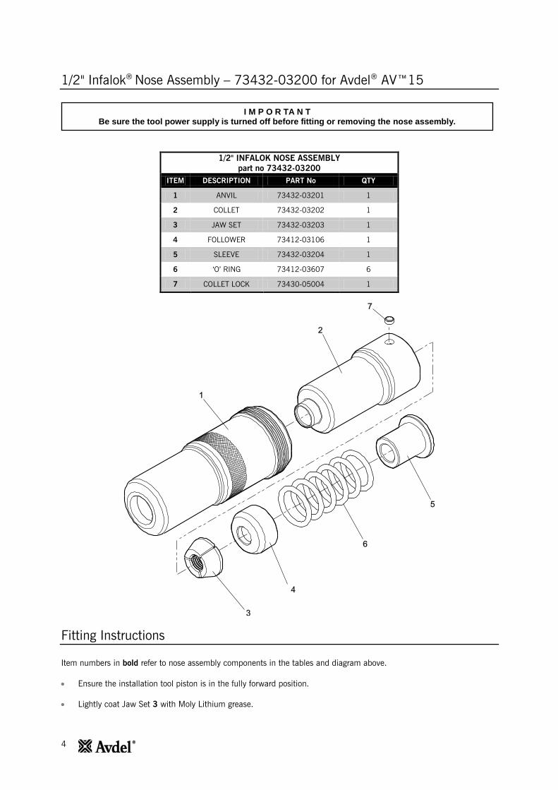
1/2" Infalok®
Nose Assembly – 73432-03200 for Avdel® AV™15
1/2" INFALOK NOSE ASSEMBLY
part no 73432-03200
ITEM DESCRIPTION PART No QTY
1 ANVIL 73432-03201 1
2 COLLET 73432-03202 1
3 JAW SET 73432-03203 1
4 FOLLOWER 73412-03106 1
5 SLEEVE 73432-03204 1
6 ‘O’ RING 73412-03607 6
7 COLLET LOCK 73430-05004 1
Fitting Instructions
Item numbers in bold refer to nose assembly components in the tables and diagram above.
Ensure the installation tool piston is in the fully forward position.
Lightly coat Jaw Set 3 with Moly Lithium grease.
I M P O R TA N T Be sure the tool power supply is turned off before fitting or removing the nose assembly.
5
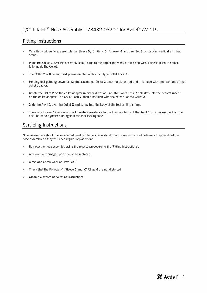
1/2" Infalok® Nose Assembly – 73432-03200 for Avdel
® AV™15
Fitting Instructions
On a flat work surface, assemble the Sleeve 5, ‘O’ Rings 6, Follower 4 and Jaw Set 3 by stacking vertically in that
order.
Place the Collet 2 over the assembly stack, slide to the end of the work surface and with a finger, push the stack
fully inside the Collet.
The Collet 2 will be supplied pre-assembled with a ball type Collet Lock 7.
Holding tool pointing down, screw the assembled Collet 2 onto the piston rod until it is flush with the rear face of the
collet adaptor.
Rotate the Collet 2 on the collet adapter in either direction until the Collet Lock 7 ball slots into the nearest indent
on the collet adapter. The Collet Lock 7 should be flush with the exterior of the Collet 2.
Slide the Anvil 1 over the Collet 2 and screw into the body of the tool until it is firm.
There is a locking 'O' ring which will create a resistance to the final few turns of the Anvil 1. It is imperative that the
anvil be hand tightened up against the rear locking face.
Servicing Instructions
Nose assemblies should be serviced at weekly intervals. You should hold some stock of all internal components of the
nose assembly as they will need regular replacement.
Remove the nose assembly using the reverse procedure to the ‘Fitting instructions’.
Any worn or damaged part should be replaced.
Clean and check wear on Jaw Set 3.
Check that the Follower 4, Sleeve 5 and ‘O’ Rings 6 are not distorted.
Assemble according to fitting instructions.

6
1/2" Infalok®
Nose Assembly – 73433-03200 for Avdel® AV™15
1/2" INFALOK NOSE ASSEMBLY
part no 73433-03200
ITEM DESCRIPTION PART No QTY
1 ANVIL 73432-03201 1
2 EJECTOR 73412-03109 1
3 COLLET 73433-03102 1
4 RELEASE 73412-03110 1
5 JAW SET 73412-03103 1
6 FOLLOWER 73412-03106 1
7 ‘O’ RING 73412-03607 6
8 SLEEVE 73432-03204 1
9 COLLET LOCK 73430-05004 1
I M P O R TA N T Be sure the tool power supply is turned off before fitting or removing the nose assembly.
7
1/2" Infalok® Nose Assembly – 73433-03200 for Avdel
® AV™15
Fitting Instructions
Item numbers in bold refer to nose assembly components in the tables and diagram above.
Ensure the installation tool piston is in the fully forward position.
Lightly coat Jaws 5 with Moly Lithium grease.
On a flat work surface, assemble the Sleeve 8, ‘O’ Rings 7, Follower 6 and Jaws 5 by stacking vertically in that
order.
The Collet 3 will be supplied pre-assembled with the Collar Ejector 2, jaw Release 4 and with a ball type Collet Lock
9.
Place the Collet 3 over the assembly stack, slide to the end of the work surface and with a finger, push the stack
fully inside the Collet.
Holding tool pointing down, screw the assembled Collet 3 onto the Collet Adapter until it is flush with the rear face
of the collet adaptor.
Rotate the Collet 3 on the collet adapter in either direction until the Collet Lock 9 ball slots into the nearest indent
on the collet adapter. The Collet Lock should be flush with the exterior of the Collet.
Slide the Anvil 1 over the Collet 3 and screw into the body of the tool until it is firm.
There is a locking 'O' ring which will create a resistance to the final few turns of the Anvil 1. It is imperative that the
anvil be hand tightened up against the rear locking face.
Correct installation of the nose assembly can be gauged by the free movement of the correct size pintail through the
assembled jaws in the nose.
Servicing Instructions
Nose assemblies should be serviced at weekly intervals. You should hold some stock of all internal components of the
nose assembly as they will need regular replacement.
Remove the nose assembly using the reverse procedure to the ‘Fitting Instructions’.
Any worn or damaged part should be replaced.
Clean and check wear on Jaws 5.
Check that the collar Ejector 2, Follower 6, Sleeve 8 and ‘O’ Rings 7 are not distorted.
To remove a damaged or worn collar Ejector 2 cut at a point between the flange of the ejector and the end of Collet
3. The collar Ejector 2 and jaw Release 4 can then be separated and removed from Collet 3.
When assembling a new collar Ejector 2 and jaw Release 4 in the Collet 3, first ensure that the threads are clean,
before applying Loctite® 243 and screwing the two parts together within Collet 3.
Assemble according to the ‘Fitting Instructions’.
8
1/2" Infalok®
Nose Assembly – Huck 2620 Tool
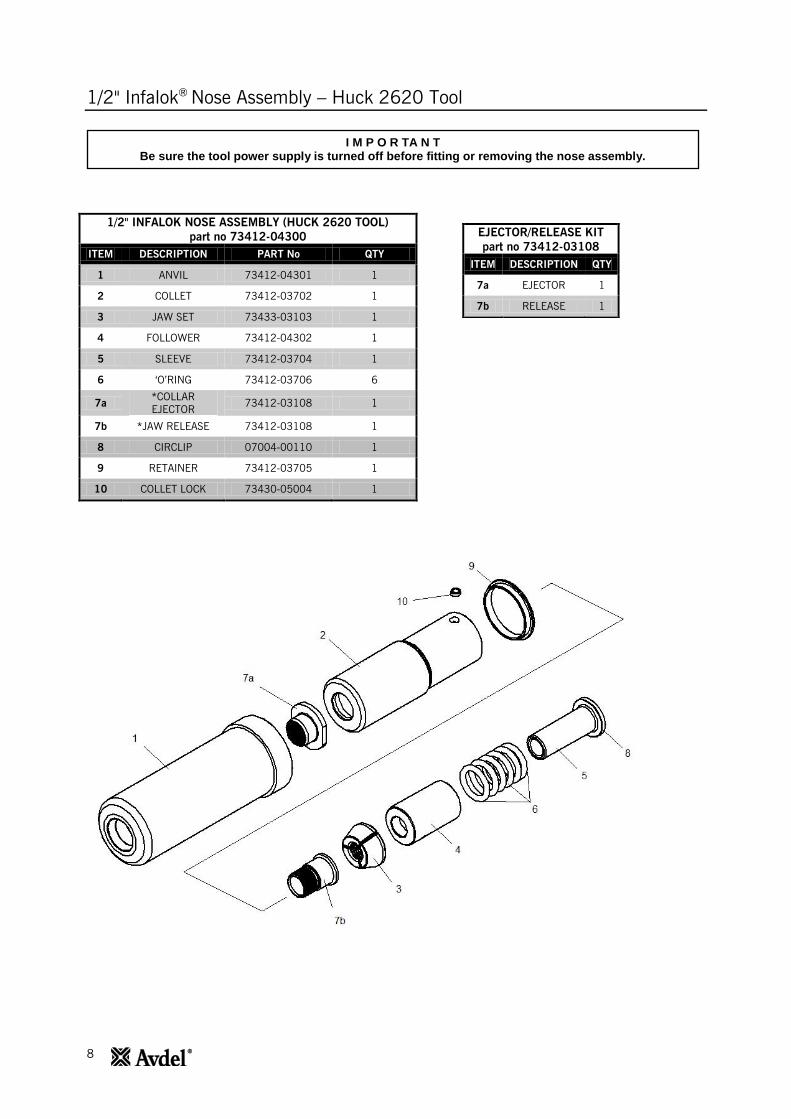
1/2" INFALOK NOSE ASSEMBLY (HUCK 2620 TOOL)
part no 73412-04300
ITEM DESCRIPTION PART No QTY
1 ANVIL 73412-04301 1
2 COLLET 73412-03702 1
3 JAW SET 73433-03103 1
4 FOLLOWER 73412-04302 1
5 SLEEVE 73412-03704 1
6 ‘O’RING 73412-03706 6
7a *COLLAR
EJECTOR 73412-03108 1
7b *JAW RELEASE 73412-03108 1
8 CIRCLIP 07004-00110 1
9 RETAINER 73412-03705 1
10 COLLET LOCK 73430-05004 1
EJECTOR/RELEASE KIT
part no 73412-03108
ITEM DESCRIPTION QTY
7a EJECTOR 1
7b RELEASE 1
I M P O R TA N T Be sure the tool power supply is turned off before fitting or removing the nose assembly.
9
1/2" Infalok®
Nose Assembly – Huck 2620 Tool
Fitting Instructions
Item numbers in bold refer to nose assembly components in the table and illustration above.
Lightly coat Jaw Set 3 with Moly Lithium grease.
On a flat work surface, assemble Sleeve 5, ‘O’ Rings 6, Follower 4 and Jaw Set 3 by stacking vertically in that
order.
The Collet 2 will be supplied pre-assembled with Collar Ejector 7a and Jaw Release 7b.
Place Collet 2 over the assembled stack, slide to the end of the work surface and with a finger push the stack
fully inside Collet 2.
Holding the tool pointing down, screw the assembled collet fully onto the tool piston rod.
Insert Collet Lock 10 into Collet 2. Unscrew Collet 2 until Collet Lock 10 slots into the nearest groove on piston
rod. The Collet Lock 10 should be flush with the exterior of Collet 2.
Assemble Anvil 1 and retainer 9 over assembly.
Servicing Instructions
Nose assemblies should be serviced at weekly intervals. You should hold some stock of all internal components
of the nose assembly as they will need regular replacement.
Any worn or damaged part should be replaced.
Clean and check wear on Jaw Set 3.
Check that Collar Ejector 7a, Collet 2, Sleeve 5 and ‘O’ Rings 6 are not distorted.
To remove a damaged or worn Collar Ejector 7a, slide the Collar Ejector 7b out of Collet 2 as far as possible.
Cut through Jaw Release 7b between the flange of Collar Ejector 7a and the front face of Collet 2. Invert Collet
2 and push out the remains of Jaw release 7b.
When assembling a new Collar Ejector 7a and Jaw Release 7b in Collet 2, first ensure that the threads are
clean, before applying Loctite® 243 and screwing the two parts together within Collet 2.
Assemble according to the ‘Fitting Instructions’.
10
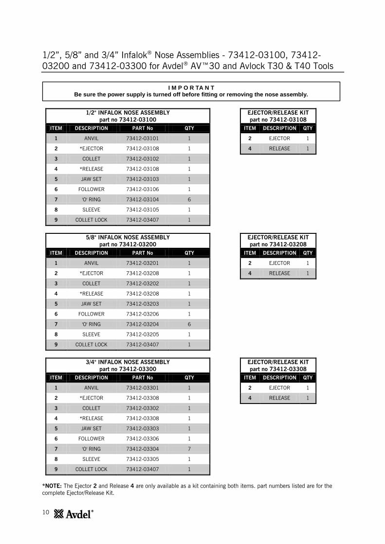
1/2”, 5/8” and 3/4” Infalok® Nose Assemblies - 73412-03100, 73412-
03200 and 73412-03300 for Avdel® AV™30 and Avlock T30 & T40 Tools
1/2" INFALOK NOSE ASSEMBLY
part no 73412-03100
ITEM DESCRIPTION PART No QTY
1 ANVIL 73412-03101 1
2 *EJECTOR 73412-03108 1
3 COLLET 73412-03102 1
4 *RELEASE 73412-03108 1
5 JAW SET 73412-03103 1
6 FOLLOWER 73412-03106 1
7 'O' RING 73412-03104 6
8 SLEEVE 73412-03105 1
9 COLLET LOCK 73412-03407 1
EJECTOR/RELEASE KIT
part no 73412-03108
ITEM DESCRIPTION QTY
2 EJECTOR 1
4 RELEASE 1
5/8" INFALOK NOSE ASSEMBLY
part no 73412-03200
ITEM DESCRIPTION PART No QTY
1 ANVIL 73412-03201 1
2 *EJECTOR 73412-03208 1
3 COLLET 73412-03202 1
4 *RELEASE 73412-03208 1
5 JAW SET 73412-03203 1
6 FOLLOWER 73412-03206 1
7 'O' RING 73412-03204 6
8 SLEEVE 73412-03205 1
9 COLLET LOCK 73412-03407 1
EJECTOR/RELEASE KIT
part no 73412-03208
ITEM DESCRIPTION QTY
2 EJECTOR 1
4 RELEASE 1
3/4" INFALOK NOSE ASSEMBLY
part no 73412-03300
ITEM DESCRIPTION PART No QTY
1 ANVIL 73412-03301 1
2 *EJECTOR 73412-03308 1
3 COLLET 73412-03302 1
4 *RELEASE 73412-03308 1
5 JAW SET 73412-03303 1
6 FOLLOWER 73412-03306 1
7 'O' RING 73412-03304 7
8 SLEEVE 73412-03305 1
9 COLLET LOCK 73412-03407 1
EJECTOR/RELEASE KIT
part no 73412-03308
ITEM DESCRIPTION QTY
2 EJECTOR 1
4 RELEASE 1
*NOTE: The Ejector 2 and Release 4 are only available as a kit containing both items. part numbers listed are for the
complete Ejector/Release Kit.
I M P O R TA N T Be sure the power supply is turned off before fitting or removing the nose assembly.

11
1/2”, 5/8” and 3/4” Infalok® Nose Assemblies - 73412-03100, 73412-
03200 and 73412-03300 for Avdel® AV™30 and Avlock T30 & T40 Tools
Fitting Instructions
Lightly coat Jaw Set 5 with Moly Lithium grease.
On a flat work surface, assemble Sleeve 8, ‘O’ Rings 7, Follower 6 and Jaw Set 5 by stacking vertically in that order.
The Collet 3 will be supplied pre-assembled with the collar Ejector 2, jaw Release 4 and with a ball type Collet Lock
9.
Carefully lower Collet 3 over the assembled components, slide to the edge of the work surface and with a finger,
push the assembled components fully inside the collet.
Holding the tool pointing down, screw the assembled collet fully onto the piston rod until it is flush with end of the
collet adaptor.
Rotate Collet 3 on the collet adapter in either direction until Collet Lock 9 slots into the nearest groove on the collet
adaptor. The Collet Lock 9 should be flush with the exterior of Collet 3.
Slide Anvil 1 over Collet 3 and screw into the anvil adaptor until it is firm.
There is a locking ‘O’ Ring which will create a resistance to the final few turns of the nose casing. It is imperative
that the nose casing be hand tightened up against the rear locking face.
Correct installation of the nose assembly can be gauged by the free movement of the correct size pintail through the
assembled jaws in the nose.
12
1/2”, 5/8” and 3/4” Infalok® Nose Assemblies - 73412-03100, 73412-
03200 and 73412-03300 for Avdel® AV™30 and Avlock T30 & T40 Tools
Servicing Instructions
Nose assemblies should be serviced at weekly intervals. You should hold some stock of all internal components of the
nose assembly as they will need regular replacement.
Remove the nose assembly using the reverse procedure to the ‘Fitting Instructions’.
Any worn or damaged part should be replaced.
Clean and check wear on Jaw Set 5.
Check that the collar Ejector 2, Follower 6, Sleeve 8 and ‘O’ Rings 7 are not distorted.
To remove a damaged or worn collar Ejector 2 cut at a point between the flange of the ejector and the end of Collet
3. The collar Ejector 2 and jaw Release 4 can then be separated and removed from Collet 3.
When assembling a new collar Ejector 2 and jaw Release 4 in the Collet 3, first ensure that the threads are clean,
before applying Loctite® 243 and screwing the two parts together within Collet 3.
Assemble according to the ‘Fitting Instructions’.
13
5/8" Infalok®
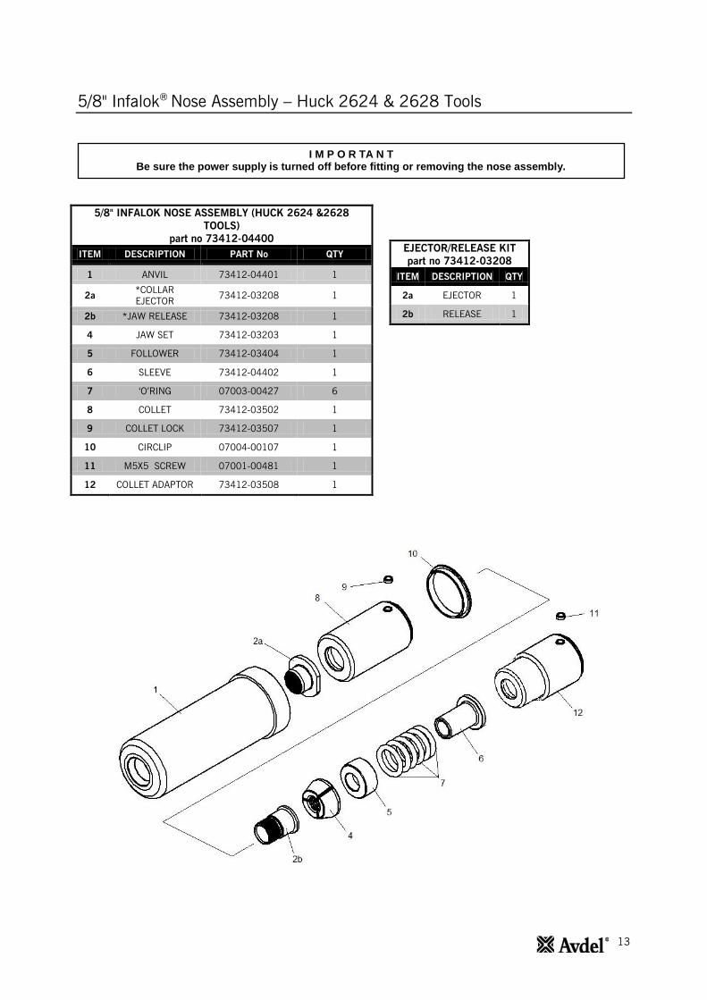
Nose Assembly – Huck 2624 & 2628 Tools
5/8" INFALOK NOSE ASSEMBLY (HUCK 2624 &2628
TOOLS)
part no 73412-04400
ITEM DESCRIPTION PART No QTY
1 ANVIL 73412-04401 1
2a *COLLAR
EJECTOR 73412-03208 1
2b *JAW RELEASE 73412-03208 1
4 JAW SET 73412-03203 1
5 FOLLOWER 73412-03404 1
6 SLEEVE 73412-04402 1
7 ‘O’RING 07003-00427 6
8 COLLET 73412-03502 1
9 COLLET LOCK 73412-03507 1
10 CIRCLIP 07004-00107 1
11 M5X5 SCREW 07001-00481 1
12 COLLET ADAPTOR 73412-03508 1
EJECTOR/RELEASE KIT
part no 73412-03208
ITEM DESCRIPTION QTY
2a EJECTOR 1
2b RELEASE 1
I M P O R TA N T Be sure the power supply is turned off before fitting or removing the nose assembly.
14
5/8" Infalok®
Nose Assembly – Huck 2624 & 2628 Tools
Fitting Instructions
Item numbers in bold refer to nose assembly components in the table and illustration above.
Lightly coat Jaws 4 with Moly Lithium grease.
On a flat work surface, assemble Sleeve 6, ‘O’ Rings 7, Follower 5 and Jaws 4 by stacking vertically in that order.
The Collet 8 will be supplied pre-assembled with Collar Ejector 2a and Jaw Release 2b.
Place Collet 8 over the assembled stack, slide to the end of the work surface and with a finger push the stack fully
inside Collet 8.
Screw Collet Adaptor 12 fully into the collet assembly. The shoulder of Collet Adaptor 12 should come into contact
with the rear of Collet 8.
Insert Collet Lock 9 into Collet 8. Unscrew Collet Adaptor 12 until Collet Lock 9 slots into the nearest groove. The
Collet Lock 9 should be flush with the exterior of Collet 8.
Servicing Instructions
Nose assemblies should be serviced at weekly intervals. You should hold some stock of all internal components of the
nose assembly as they will need regular replacement.
Remove the nose assembly using the reverse procedure to the ‘Fitting Instructions’.
Any worn or damaged part should be replaced.
Clean and check wear on Jaws 4.
Check that Collar Ejector 2, Follower 5, Sleeve 6 and ‘O’ Rings 7 are not distorted.
To remove a damaged or worn Collar Ejector 2 cut at a point between the flange of the ejector and the end of
Collet 8. The Collar Ejector 2 and Jaw Release 3 can then be separated and removed from Collet 4.
When assembling a new Collar Ejector 2 and Jaw Release 3 in Collet 8, first ensure that the threads are clean,
before applying Loctite® 243 and screwing the two parts together within Collet 8.
Assemble according to the ‘Fitting Instructions’.
15
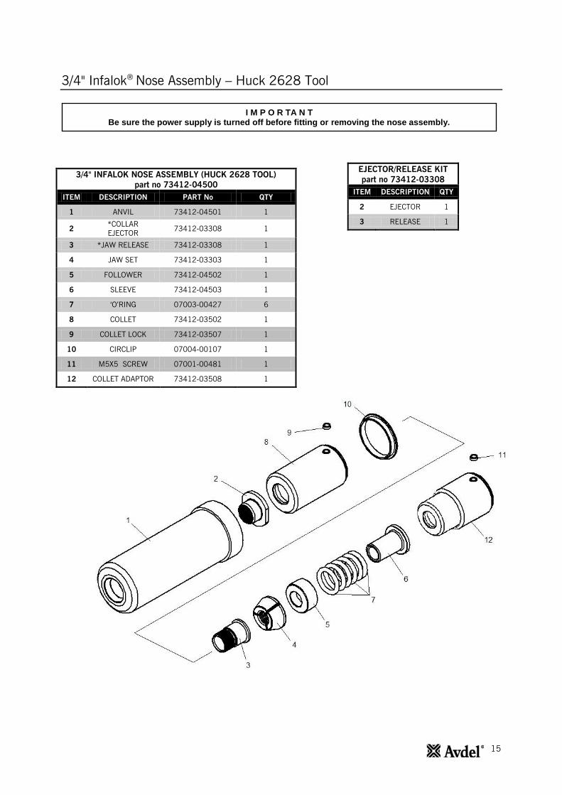
3/4" Infalok®
Nose Assembly – Huck 2628 Tool
EJECTOR/RELEASE KIT
part no 73412-03308
ITEM DESCRIPTION QTY
2 EJECTOR 1
3 RELEASE 1
3/4" INFALOK NOSE ASSEMBLY (HUCK 2628 TOOL)
part no 73412-04500
ITEM DESCRIPTION PART No QTY
1 ANVIL 73412-04501 1
2 *COLLAR
EJECTOR 73412-03308 1
3 *JAW RELEASE 73412-03308 1
4 JAW SET 73412-03303 1
5 FOLLOWER 73412-04502 1
6 SLEEVE 73412-04503 1
7 ‘O’RING 07003-00427 6
8 COLLET 73412-03502 1
9 COLLET LOCK 73412-03507 1
10 CIRCLIP 07004-00107 1
11 M5X5 SCREW 07001-00481 1
12 COLLET ADAPTOR 73412-03508 1
I M P O R TA N T Be sure the power supply is turned off before fitting or removing the nose assembly.
16
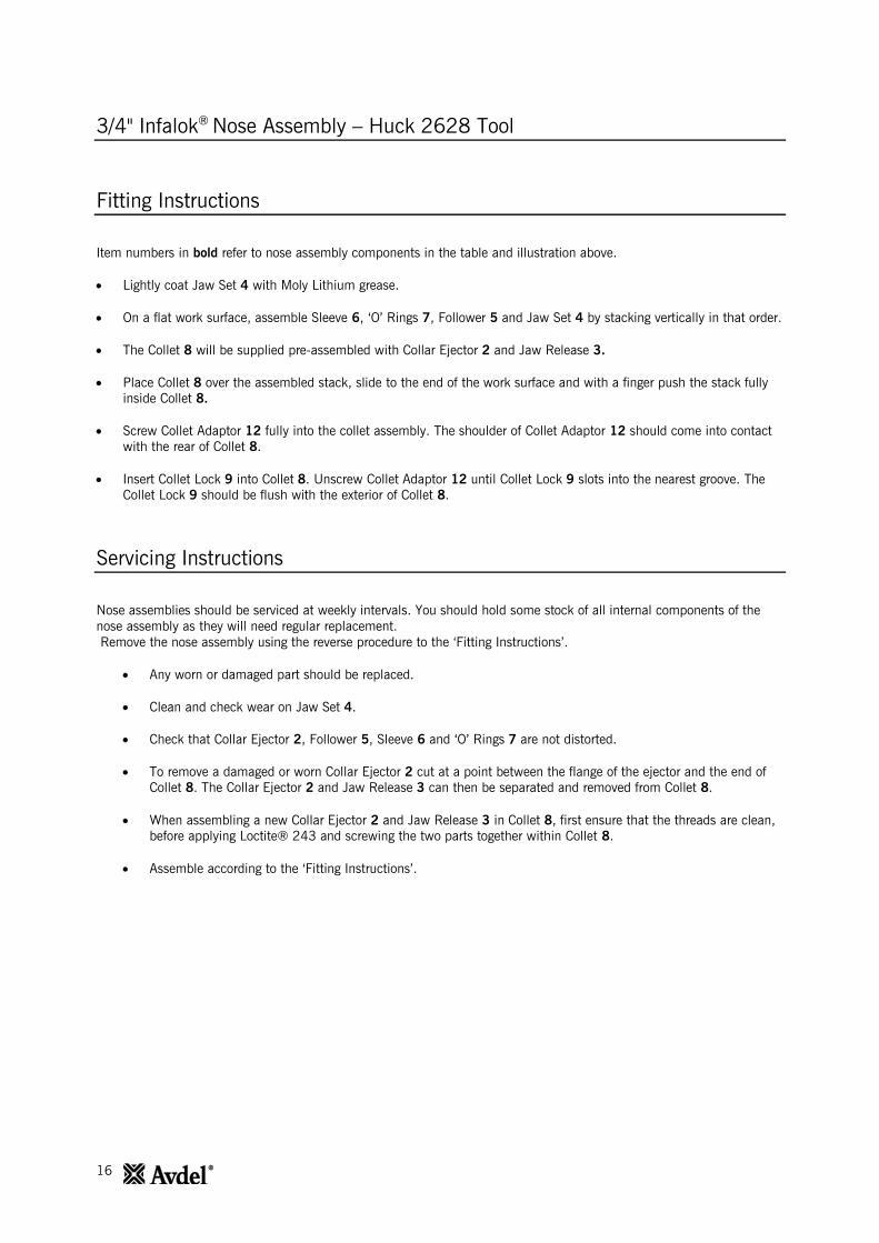
3/4" Infalok®
Nose Assembly – Huck 2628 Tool
Fitting Instructions
Item numbers in bold refer to nose assembly components in the table and illustration above.
Lightly coat Jaw Set 4 with Moly Lithium grease.
On a flat work surface, assemble Sleeve 6, ‘O’ Rings 7, Follower 5 and Jaw Set 4 by stacking vertically in that order.
The Collet 8 will be supplied pre-assembled with Collar Ejector 2 and Jaw Release 3.
Place Collet 8 over the assembled stack, slide to the end of the work surface and with a finger push the stack fully
inside Collet 8.
Screw Collet Adaptor 12 fully into the collet assembly. The shoulder of Collet Adaptor 12 should come into contact
with the rear of Collet 8.
Insert Collet Lock 9 into Collet 8. Unscrew Collet Adaptor 12 until Collet Lock 9 slots into the nearest groove. The
Collet Lock 9 should be flush with the exterior of Collet 8.
Servicing Instructions
Nose assemblies should be serviced at weekly intervals. You should hold some stock of all internal components of the
nose assembly as they will need regular replacement.
Remove the nose assembly using the reverse procedure to the ‘Fitting Instructions’.
Any worn or damaged part should be replaced.
Clean and check wear on Jaw Set 4.
Check that Collar Ejector 2, Follower 5, Sleeve 6 and ‘O’ Rings 7 are not distorted.
To remove a damaged or worn Collar Ejector 2 cut at a point between the flange of the ejector and the end of
Collet 8. The Collar Ejector 2 and Jaw Release 3 can then be separated and removed from Collet 8.
When assembling a new Collar Ejector 2 and Jaw Release 3 in Collet 8, first ensure that the threads are clean,
before applying Loctite® 243 and screwing the two parts together within Collet 8.
Assemble according to the ‘Fitting Instructions’.
17
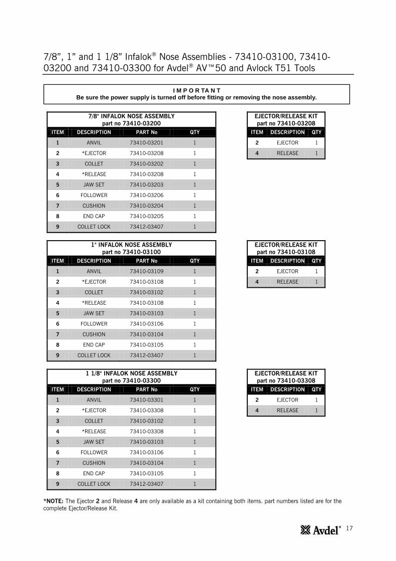
7/8”, 1” and 1 1/8” Infalok® Nose Assemblies - 73410-03100, 73410-
03200 and 73410-03300 for Avdel® AV™50 and Avlock T51 Tools
7/8" INFALOK NOSE ASSEMBLY
part no 73410-03200
ITEM DESCRIPTION PART No QTY
1 ANVIL 73410-03201 1
2 *EJECTOR 73410-03208 1
3 COLLET 73410-03202 1
4 *RELEASE 73410-03208 1
5 JAW SET 73410-03203 1
6 FOLLOWER 73410-03206 1
7 CUSHION 73410-03204 1
8 END CAP 73410-03205 1
9 COLLET LOCK 73412-03407 1
EJECTOR/RELEASE KIT
part no 73410-03208
ITEM DESCRIPTION QTY
2 EJECTOR 1
4 RELEASE 1
1" INFALOK NOSE ASSEMBLY
part no 73410-03100
ITEM DESCRIPTION PART No QTY
1 ANVIL 73410-03109 1
2 *EJECTOR 73410-03108 1
3 COLLET 73410-03102 1
4 *RELEASE 73410-03108 1
5 JAW SET 73410-03103 1
6 FOLLOWER 73410-03106 1
7 CUSHION 73410-03104 1
8 END CAP 73410-03105 1
9 COLLET LOCK 73412-03407 1
EJECTOR/RELEASE KIT
part no 73410-03108
ITEM DESCRIPTION QTY
2 EJECTOR 1
4 RELEASE 1
1 1/8" INFALOK NOSE ASSEMBLY
part no 73410-03300
ITEM DESCRIPTION PART No QTY
1 ANVIL 73410-03301 1
2 *EJECTOR 73410-03308 1
3 COLLET 73410-03102 1
4 *RELEASE 73410-03308 1
5 JAW SET 73410-03103 1
6 FOLLOWER 73410-03106 1
7 CUSHION 73410-03104 1
8 END CAP 73410-03105 1
9 COLLET LOCK 73412-03407 1
EJECTOR/RELEASE KIT
part no 73410-03308
ITEM DESCRIPTION QTY
2 EJECTOR 1
4 RELEASE 1
*NOTE: The Ejector 2 and Release 4 are only available as a kit containing both items. part numbers listed are for the
complete Ejector/Release Kit.
I M P O R TA N T Be sure the power supply is turned off before fitting or removing the nose assembly.
18
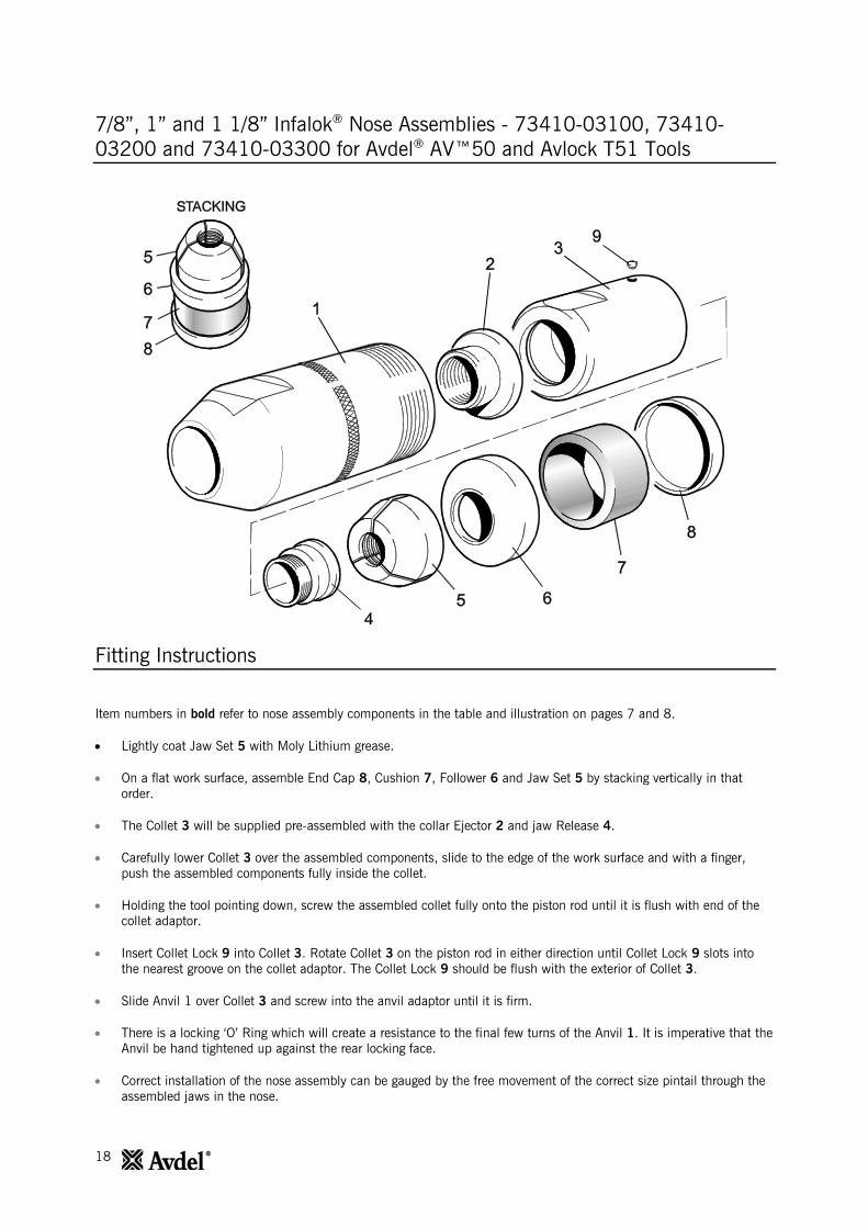
7/8”, 1” and 1 1/8” Infalok® Nose Assemblies - 73410-03100, 73410-
03200 and 73410-03300 for Avdel® AV™50 and Avlock T51 Tools
Fitting Instructions
Item numbers in bold refer to nose assembly components in the table and illustration on pages 7 and 8.
Lightly coat Jaw Set 5 with Moly Lithium grease.
On a flat work surface, assemble End Cap 8, Cushion 7, Follower 6 and Jaw Set 5 by stacking vertically in that
order.
The Collet 3 will be supplied pre-assembled with the collar Ejector 2 and jaw Release 4.
Carefully lower Collet 3 over the assembled components, slide to the edge of the work surface and with a finger,
push the assembled components fully inside the collet.
Holding the tool pointing down, screw the assembled collet fully onto the piston rod until it is flush with end of the
collet adaptor.
Insert Collet Lock 9 into Collet 3. Rotate Collet 3 on the piston rod in either direction until Collet Lock 9 slots into
the nearest groove on the collet adaptor. The Collet Lock 9 should be flush with the exterior of Collet 3.
Slide Anvil 1 over Collet 3 and screw into the anvil adaptor until it is firm.
There is a locking ‘O’ Ring which will create a resistance to the final few turns of the Anvil 1. It is imperative that the
Anvil be hand tightened up against the rear locking face.
Correct installation of the nose assembly can be gauged by the free movement of the correct size pintail through the
assembled jaws in the nose.
19
7/8”, 1” and 1 1/8” Infalok® Nose Assemblies - 73410-03100, 73410-
03200 and 73410-03300 for Avdel® AV™50 and Avlock T51 Tools
Servicing Instructions
Nose assemblies should be serviced at weekly intervals. You should hold some stock of all internal components of the
nose assembly as they will need regular replacement.
Remove the nose assembly using the reverse procedure to the ‘Fitting Instructions’.
Any worn or damaged part should be replaced.
Clean and check wear on Jaw Set 5.
Check that collar Ejector 2, Follower 6, End Cap 8 and Cushion 7 are not distorted.
To remove a damaged or worn collar Ejector 2 cut at a point between the flange of the ejector and the end of Collet
3. The collar Ejector 2 and jaw Release 4 can then be separated and removed from Collet 3.
When assembling a new collar Ejector 2 and jaw Release 4 in Collet 3, first ensure that the threads are clean, before
applying Loctite® 243 and screwing the two parts together within Collet 3.
Assemble according to the ‘Fitting Instructions’.
20
7/8" Infalok®
Nose Assembly – Huck 506 Tool
EJECTOR/RELEASE KIT
part no 73410-03208
ITEM DESCRIPTION QTY
4a EJECTOR 1
4b RELEASE 1
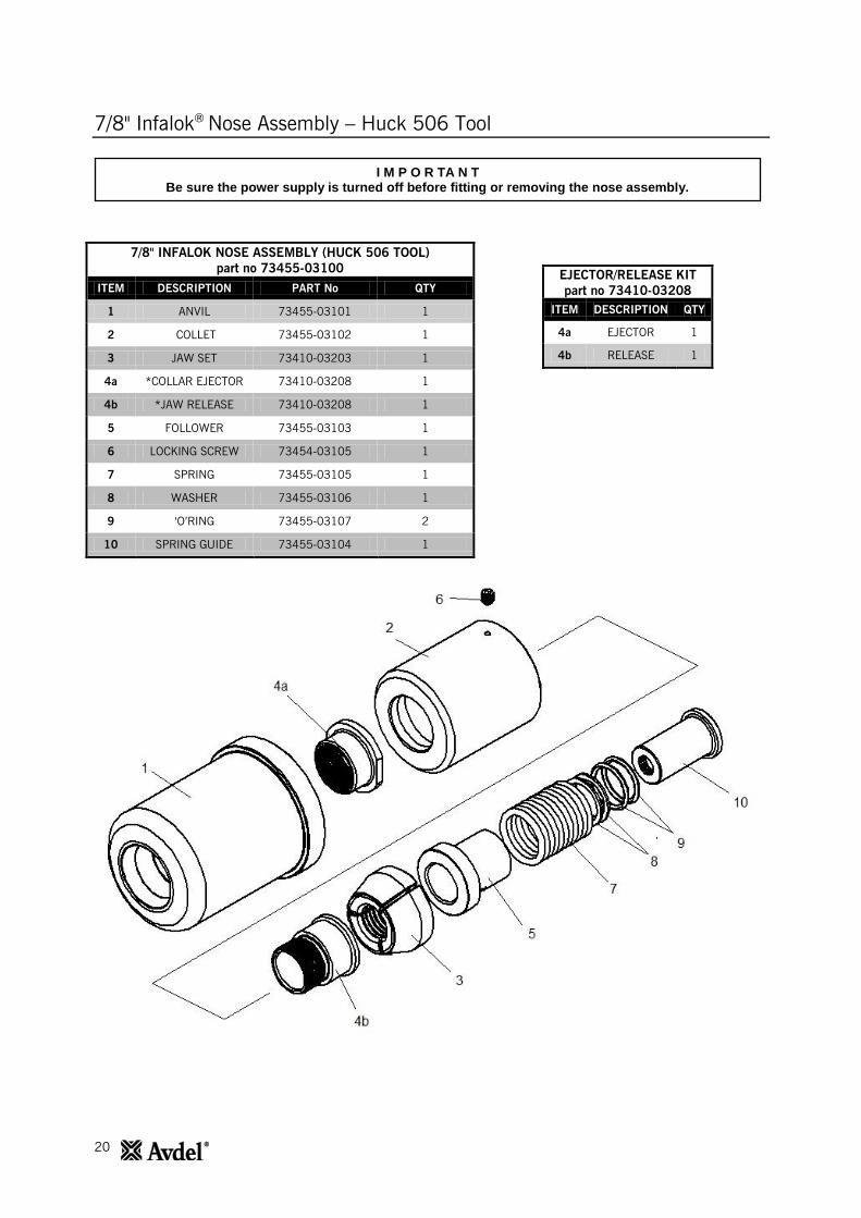
7/8" INFALOK NOSE ASSEMBLY (HUCK 506 TOOL)
part no 73455-03100
ITEM DESCRIPTION PART No QTY
1 ANVIL 73455-03101 1
2 COLLET 73455-03102 1
3 JAW SET 73410-03203 1
4a *COLLAR EJECTOR 73410-03208 1
4b *JAW RELEASE 73410-03208 1
5 FOLLOWER 73455-03103 1
6 LOCKING SCREW 73454-03105 1
7 SPRING 73455-03105 1
8 WASHER 73455-03106 1
9 ‘O’RING 73455-03107 2
10 SPRING GUIDE 73455-03104 1
I M P O R TA N T Be sure the power supply is turned off before fitting or removing the nose assembly.
21
7/8" Infalok®
Nose Assembly – Huck 506 Tool
Fitting Instructions
Item numbers in bold refer to nose assembly components in the table and illustration above.
Lightly coat Jaw Set 3 with Moly Lithium grease.
Assemble Spring Guide 10, ‘O’ Rings 9, Washer 8 and Spring 7.
The Collet 2 will be supplied pre-assembled with Collar Ejector 4a and Jaw Release 4b.
Place Collet 2 over the assembled stack, slide to the end of the work surface and with a finger push the stack fully
inside Collet 2.
Screw Collet 2 and assembled stack fully onto the Tool Collet Adaptor (fitted to tool).
Insert Locking Screw 6 into Collet 2. Unscrew Collet 2 until Locking Screw 6 can be tightened into the nearest
groove in the Tool Collet adaptor. When assembled the Locking Screw 6 should be flush with the exterior of Collet 2.
Servicing Instructions
Nose assemblies should be serviced at weekly intervals. You should hold some stock of all internal components of the
nose assembly as they will need regular replacement.
Remove the nose assembly using the reverse procedure to the ‘Fitting Instructions’.
Any worn or damaged part should be replaced.
Clean and check wear on Jaw Set 3.
Check that Collar Ejector 4a, Follower 5, Spring Guide 10 and ‘O’ Rings 9 are not distorted.
To remove a damaged or worn Collar Ejector 4a cut at a point between the flange of the ejector and the end of
Collet 2. The Collar Ejector 4a and Jaw Release 4b can then be separated and removed from Collet 2.
When assembling a new Collar Ejector 4a and Jaw Release 4b in Collet 2, first ensure that the threads are
clean, before applying Loctite® 243 and screwing the two parts together within Collet 2.
Assemble according to the ‘Fitting Instructions’.
22
1" Infalok®
Nose Assembly – Huck 507 Tool
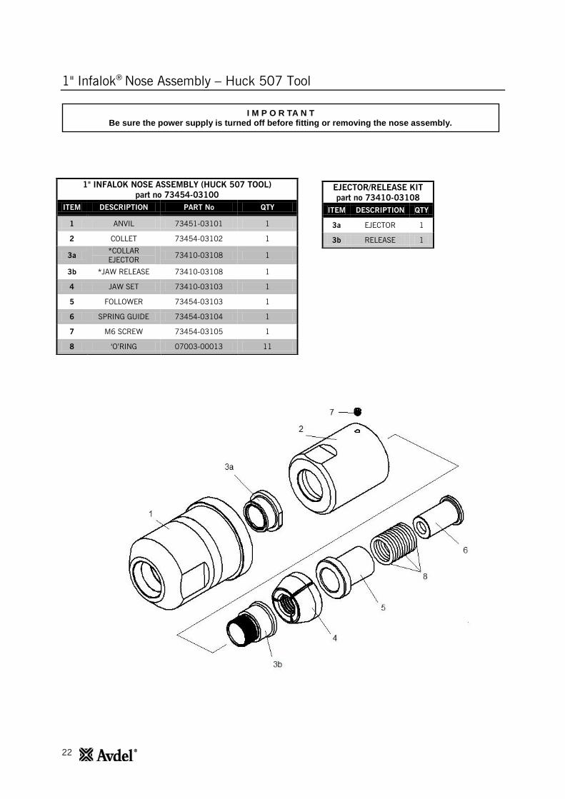
1" INFALOK NOSE ASSEMBLY (HUCK 507 TOOL)
part no 73454-03100
ITEM DESCRIPTION PART No QTY
1 ANVIL 73451-03101 1
2 COLLET 73454-03102 1
3a *COLLAR
EJECTOR 73410-03108 1
3b *JAW RELEASE 73410-03108 1
4 JAW SET 73410-03103 1
5 FOLLOWER 73454-03103 1
6 SPRING GUIDE 73454-03104 1
7 M6 SCREW 73454-03105 1
8 ‘O’RING 07003-00013 11
EJECTOR/RELEASE KIT
part no 73410-03108
ITEM DESCRIPTION QTY
3a EJECTOR 1
3b RELEASE 1
I M P O R TA N T Be sure the power supply is turned off before fitting or removing the nose assembly.
23
1" Infalok®
Nose Assembly – Huck 507 Tool
Fitting Instructions
Item numbers in bold refer to nose assembly components in the table and illustration above.
Lightly coat Jaw Set 4 with Moly Lithium grease.
Assemble Spring Guide 6, ‘O’ Rings 8, Follower 5 and Jaw Set 4 in stack.
The Collet 2 will be supplied pre-assembled with Collar Ejector 3a and Jaw Release 3b.
Place Collet 2 over the assembled stack, push the stack fully inside Collet 2.
Screw Collet 2 and assembled stack fully onto Tool Piston Collet Adaptor (fitted to tool).
Insert Screw 7 into Collet 2. Unscrew Collet Adaptor 2 until Screw 7 can be tightened into nearest groove in the Tool
Collet Adaptor. The Screw 7 should be flush with the exterior of Collet 2.
Servicing Instructions
Nose assemblies should be serviced at weekly intervals. You should hold some stock of all internal components of the
nose assembly as they will need regular replacement.
Remove the nose assembly using the reverse procedure to the ‘Fitting Instructions’.
Any worn or damaged part should be replaced.
Clean and check wear on Jaw Set 4.
Check that Collar Ejector 3a, Follower 5, Sleeve 6 and ‘O’ Rings 8 are not distorted.
To remove a damaged or worn Collar Ejector 3a cut at a point between the flange of the ejector and the end of
Collet 2. The Collar Ejector 3a and Jaw Release 3b can then be separated and removed from Collet 2.
When assembling a new Collar Ejector 3a and Jaw Release 3b in Collet 2, first ensure that the threads are
clean, before applying Loctite® 243 and screwing the two parts together within Collet 2.
Assemble according to the ‘Fitting Instructions’.

24
Holding your world together®
Find your closest STANLEY Engineered Fastening location on www.StanleyEngineeredFastening.com/contact
For an authorized distributor nearby please check www.StanleyEngineeredFastening.com/econtact/distributors
Manual Number Issue C/N
07900-00919 C 14/071
www.StanleyEngineeredFastening.com
© 2013 Stanley Black & Decker, Inc., Rev. 01.2014
Avdel UK Limited Pacific House, 2 Swiftfields
Welwyn Garden City, Hertfordshire AL7 1LY Tel. +44 (0)1707 292-000 · Fax -199
Avbolt®, Avdel®, Avdelok®, Avex®, Avinox®, Avseal®, Avtainer®, Hemlok®, Maxlok® and Monobolt® are trademarks of Avdel UK Limited. The names and logos of other companies mentioned herein may be trademarks of their respective owners. Data shown is subject to change without prior notice as a result of continuous product development and improvement policy. Your local Avdel representative is at your disposal should you need to confirm latest information.