Atisa Aero-Termica-Italiana S.p.A. - warma.it · a taglio termico abbinati a pannelli con spess. 49...
16
Transcript of Atisa Aero-Termica-Italiana S.p.A. - warma.it · a taglio termico abbinati a pannelli con spess. 49...


2
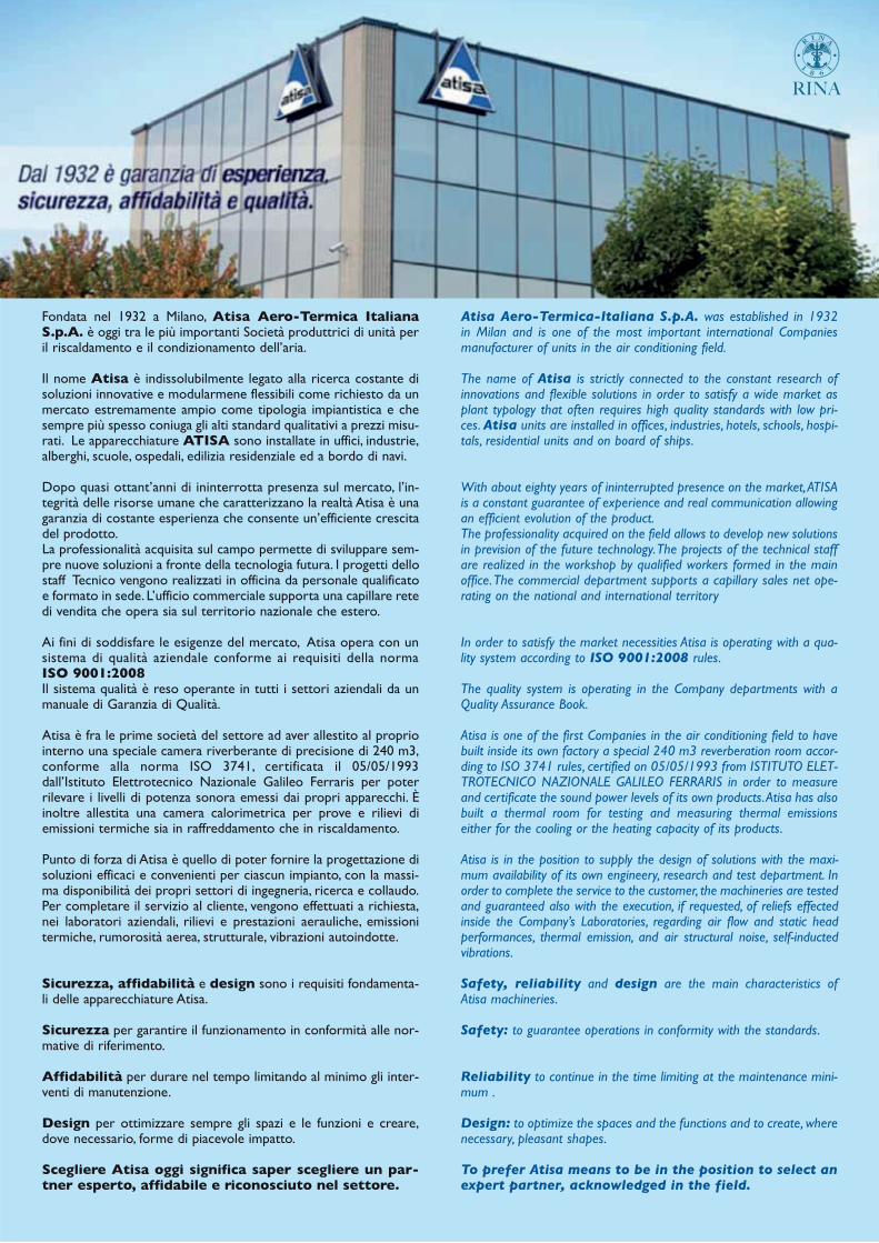
Fondata nel 1932 a Milano, Atisa Aero-Termica ItalianaS.p.A. è oggi tra le più importanti Società produttrici di unità peril riscaldamento e il condizionamento dell’aria.
Il nome Atisa è indissolubilmente legato alla ricerca costante disoluzioni innovative e modularmene flessibili come richiesto da unmercato estremamente ampio come tipologia impiantistica e chesempre più spesso coniuga gli alti standard qualitativi a prezzi misu-rati. Le apparecchiature ATISA sono installate in uffici, industrie,alberghi, scuole, ospedali, edilizia residenziale ed a bordo di navi.
Dopo quasi ottant’anni di ininterrotta presenza sul mercato, l’in-tegrità delle risorse umane che caratterizzano la realtà Atisa è unagaranzia di costante esperienza che consente un’efficiente crescitadel prodotto. La professionalità acquisita sul campo permette di sviluppare sem-pre nuove soluzioni a fronte della tecnologia futura. I progetti dellostaff Tecnico vengono realizzati in officina da personale qualificatoe formato in sede. L’ufficio commerciale supporta una capillare retedi vendita che opera sia sul territorio nazionale che estero.
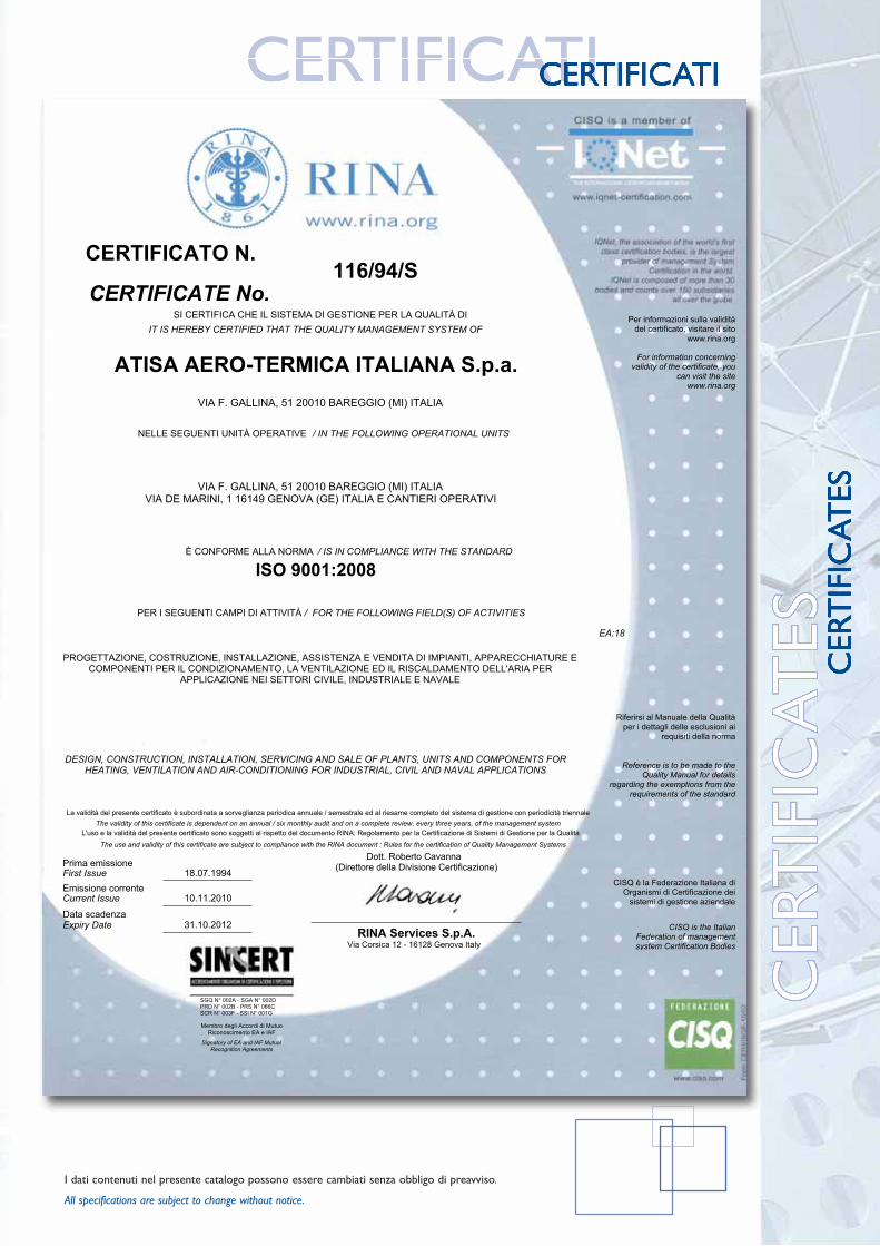
Ai fini di soddisfare le esigenze del mercato, Atisa opera con unsistema di qualità aziendale conforme ai requisiti della normaISO 9001:2008Il sistema qualità è reso operante in tutti i settori aziendali da unmanuale di Garanzia di Qualità.
Atisa è fra le prime società del settore ad aver allestito al propriointerno una speciale camera riverberante di precisione di 240 m3,conforme alla norma ISO 3741, certificata il 05/05/1993dall’Istituto Elettrotecnico Nazionale Galileo Ferraris per poterrilevare i livelli di potenza sonora emessi dai propri apparecchi. Èinoltre allestita una camera calorimetrica per prove e rilievi diemissioni termiche sia in raffreddamento che in riscaldamento.
Punto di forza di Atisa è quello di poter fornire la progettazione disoluzioni efficaci e convenienti per ciascun impianto, con la massi-ma disponibilità dei propri settori di ingegneria, ricerca e collaudo.Per completare il servizio al cliente, vengono effettuati a richiesta,nei laboratori aziendali, rilievi e prestazioni aerauliche, emissionitermiche, rumorosità aerea, strutturale, vibrazioni autoindotte.
Sicurezza, affidabilità e design sono i requisiti fondamenta-li delle apparecchiature Atisa.
Sicurezza per garantire il funzionamento in conformità alle nor-mative di riferimento.
Affidabilità per durare nel tempo limitando al minimo gli inter-venti di manutenzione.
Design per ottimizzare sempre gli spazi e le funzioni e creare,dove necessario, forme di piacevole impatto.
Scegliere Atisa oggi significa saper scegliere un par-tner esperto, affidabile e riconosciuto nel settore.
Atisa Aero-Termica-Italiana S.p.A. was established in 1932in Milan and is one of the most important international Companiesmanufacturer of units in the air conditioning field.
The name of Atisa is strictly connected to the constant research ofinnovations and flexible solutions in order to satisfy a wide market asplant typology that often requires high quality standards with low pri-ces. Atisa units are installed in offices, industries, hotels, schools, hospi-tals, residential units and on board of ships.
With about eighty years of ininterrupted presence on the market, ATISAis a constant guarantee of experience and real communication allowingan efficient evolution of the product. The professionality acquired on the field allows to develop new solutionsin prevision of the future technology. The projects of the technical staffare realized in the workshop by qualified workers formed in the mainoffice. The commercial department supports a capillary sales net ope-rating on the national and international territory
In order to satisfy the market necessities Atisa is operating with a qua-lity system according to ISO 9001:2008 rules.
The quality system is operating in the Company departments with aQuality Assurance Book.
Atisa is one of the first Companies in the air conditioning field to havebuilt inside its own factory a special 240 m3 reverberation room accor-ding to ISO 3741 rules, certified on 05/05/1993 from ISTITUTO ELET-TROTECNICO NAZIONALE GALILEO FERRARIS in order to measureand certificate the sound power levels of its own products. Atisa has alsobuilt a thermal room for testing and measuring thermal emissionseither for the cooling or the heating capacity of its products.
Atisa is in the position to supply the design of solutions with the maxi-mum availability of its own engineery, research and test department. Inorder to complete the service to the customer, the machineries are testedand guaranteed also with the execution, if requested, of reliefs effectedinside the Company’s Laboratories, regarding air flow and static headperformances, thermal emission, and air structural noise, self-inductedvibrations.
Safety, reliability and design are the main characteristics ofAtisa machineries.
Safety: to guarantee operations in conformity with the standards.
Reliability to continue in the time limiting at the maintenance mini-mum .
Design: to optimize the spaces and the functions and to create, wherenecessary, pleasant shapes.
To prefer Atisa means to be in the position to select anexpert partner, acknowledged in the field.
RINA

Le unità di trattamento aria
serie UTA, sono progettate e
realizzate in conformità alle
disposizioni della normativa
macchine 98/37/CE e
rientrano nei valori massimali
di classificazione della norma
EN 1886. Sono disponibili in
25 grandezze con portate
d’aria da 1900 a 88.000 mc/h.
Le unità di trattamento aria
UTA, consentono varie
combinazioni per soddisfare le
più ampie esigenze dei clienti.
Le unità di trattamento aria
sono realizzate con telaio in
profilati estrusi di alluminio
(antikorodol) e pannelli di
tamponamento tipo sandwich
spess. 23 o 49 mm con
interposto materiale isolante. I
componenti costituenti le
unità trattamento aria sono di
primaria marca e soggetti al
controllo in fabbrica.
Sono disponibili anche le
seguenti versioni:
- telaio in profilati di alluminio
a taglio termico abbinati a
pannelli con spess. 49 mm;
- sanificabile conforme alla
normativa DIN 1946 parte 4,
con assenza di parti interne
sporgenti e con i componenti
montati su guide per
l’estrazione.
Air handling units UTA series, are designed
and manufactured in compliance to the
Machinary Directive 98/37/CE and
comply with the best classification values
of standard EN 1886.
They are available in 25 sizes with air flow
from 1900 to 88.000 mc/h. Air handling
units UTA serie, allow various combinations
in order to satisfy customers necessities.
ATISA air handling units are realized with
structure having frame made of extruded
aluminium and internal insulated “sandwich”
panels 23 or 49 mm thickness. The
components forming Atisa’s air handling
units are high class and factory tested
products of primary brand.
The AHU are available in the following
versions:
• frame made of thermal cut aluminium
profiles thickness 49 mm;
• hygienic type complying with DIN 1946
part 4 - without internal projections and
with components fitted on special guide
rails for an easy removal.
4

5
DES
CR
IPT
ION
descrizioneDESCRIZIONE
INVOLUCRO
Costituito da struttura portante in profilati estrusi di alluminio UNI 6060/1con angoli di giunzione a 3 vie in nylon caricato con fibra di vetro.Pannellatura di tamponamento tipo sandwich disponibile negli spess. 23 mm.(fino alla grand. 38), 49 mm (per tutte le grandezze) e nelle versioni:- acciaio zincato;- acciaio zincato plastificato;- alluminio;- acciaio inox.
Le pannellature sono disponibili con i seguenti materiali isolanti:- poliuretano espanso con densità 40 Kg/(std.);- poliuretano espanso ininfiammabile classe B2 DIN 4102 certificato RINA
con densità 60 Kg/mc (a richiesta);- Lana di roccia con densità 40-60 o 100 Kg/mc.
I pannelli sono fissati al telaio mediante viti autoperforanti contenute inbussole di nylon e con interposta guarnizione in gomma per assicurarne laperfetta tenuta.Il basamento è costituito da piedini sino alla grand. 10 e da profilati di acciaiozincato (H = 120 mm) per le grandezze superiori.Le portine d’ispezione ruotano su cerniere in nylon caricato con fibra di vetroe sono complete di maniglie a serraggio progressivo con apertura di sicurezza.I tamponamenti interni possono essere realizzati in lamiera zincata, acciaioinossidabile o alluminio.
SERRANDA
Con telaio in lamiera di acciaio zincato o di alluminio con alette dello stessomateriale, coniugate tra loro per movimento contrapposto a mezzo di levismio ingranaggi e ruotanti su bussole in nylon. Sono previste con comandomanuale o predisposte per comando motorizzato. A richiesta, con alette inalluminio a profilo alare e guarnizioni di tenuta in gomma.
CASING
Self supporting structure made of extruded aluminium profiles UNI 6060/1 with 3 waysnylon angles loaded with glass fiber.Sandwich type panels available with 23 mmthickness (up to size 38), 49 mm (for every size)and in the following versions:• Galvanized steel;• Galvanized steel plastic coating;• Aluminium;• Stainless steel.
Panels are available with the following insulations:• polyurethane foam 40 Kg density;• Fire proof polyurethane foam class B2 DIN
4102 RINA certification - with density 60Kg/mc (on request);
• Rock wool 40-60 or 100 Kg/mc density.
Panels are fixed to the frame by means of selftapping screw, fitted into nylon bushes and withrubber gaskets to ensure a perfect tightening.The basement stand on feet up to size 10, theother sizes stand on galvanized steel sheet base(H = 120 mm). Inspection doors are fitted on nylon hinges loa-ded with glass fiber and are equipped with pro-gressive closing handles with safety opening.Internal metallic structure can be made of galvanized sheet, stainless steel or aluminium.
DAMPERS
Made with frame and blades in galvanized steelsheet or aluminium, coupled by means of gearsrotating on nylon bushes. They are designed forhand or motorized operation. On request,dampers can be supplied with blades made ofaluminim and tight seals made of rubber.
DESCRIPTION

6
descrizioneDESCRIZIONE
FILTRI A CELLE
con media filtrante acrilica rigenerabile autoestinguente classe 1 (DIN 53438), contenutain un telaio di lamiera zincata con reti di protezione zincate ed elettrosaldate; eff. 91%secondo ASHRAE 52.1.1992 - G4 secondo UNI EN 779. Sono montati su guide perestrazione laterale o su controtelai per estrazione frontale.
FILTRI ROTATIVI
con media filtrante sintetica a densità progressiva autoestinguente classe 1 (DIN 53438).Struttura portante in lamiera zincata; scorrimento del filtro guidato da tondini in acciaiozincato sia in ingresso che in uscita aria. Avanzamento automatico mediantemotoriduttore per alimentazione V.230/1-50 Hz comandato da pressostato differenziale;quadro elettrico di comado con circuito secondario a 24 V. Eff. 83% secondo ASHRAE52.1.1992 - G3 secondo UNI EN 779.
FILTRI A TASCHE RIGIDE
con media filtrante in carta di fibra di vetro pieghettata, idrorepellente, ritardante allafiamma, classe di reazione al fuoco M1. Telaio portante in polistirene a perfetta tenuta.Sono montati su controtelai nel senso corrente dell’aria e completi di sistema di sgancioper la rapida sostituzione. Eff. 60/80%-F6; 80/90%-F7; 95%-F9 secondo AHSRAE 52.1.1992- secondo UNI EN 779.
FILTRI A TASCHE MORBIDE
con media filtrante in fibra di vetro o fibra sintetica (a richiesta). Sono montati sucontrotelai nel senso corrente dell’aria e completi di sistema di sgancio per la rapidasostituzione. Eff. 40/50%-F5; 60/80%-F6; 80/90%-F7; 90/95%-F8 secondo AHSRAE52.1.1992 - secondo UNI EN 779.
FILTRI ASSOLUTI
ad alta efficienza con media filtrante a piccole pieghe in microfibra di vetro distanziate dafilo continuo termoplastico, idrorepellente, classe di reazione al fuoco M1. Sono montatisu controtelai in lamiera zincata con staffe e tiranti di fissaggio. Eff. 99,99% DOP test - H13CEN prEN 1822.
FILTRI AI CARBONI ATTIVI
con telaio portante in lamiera zincata e cartucce cilindriche a reti microstirate.
CELL FILTERS
with regenerable and self extinguish filter mediaclass 1 (DIN 53438) fitted inside a frame made ofgalvanized sheet with galvanized and electrowelded protection net - eff. 91% according toASHRAE 52.1.1992 - G4 - UNI EN 779. They arefitted on rails for lateral withdrawal or on counterframes for front withdrawal.
ROLL FILTERS
with progressive density syntetic filtering media selfextinguish type class 1 (DIN 53438).Self supporting structure made of galvanized sheet;filter slide driven by means of galvanized steel ballseither in the air inlet or outlet. Automatic renewalby means of electric actuator V 230/1-50 Hz. drivenby differential pressure switch; control board withsecondary circuit 24 V - 83% efficiency according toASHRAE 52.1.1992 - G3 - UNI EN 779.
RIGID BAG FILTER
with filtering media made of folded glass fibrepaper, water proof, fire reaction M1. Self supportingframe made of polistirene - perfect tight. They areinstalled on counter frames located in the airstream way and complete of clips for a quickwithdrawal. Eff.60/80%-F7; 95%-F9 according toASHRAE 52.1.1992 UNI EN 779.
SOFT BAG FILTERS
with filtering media made of folded glass fibre paperor synthetic fibre (on request). They are installed oncounter frames located in the air stream way andcomplete of clips for a quick withdrawal. Eff.40/50%-F5 - 60/80%-F6; 80/90%-F7; 90/95%-F8according to ASHRAE 52.1.1992 UNI EN 779.
ABSOLUTE FILTERS
high efficiency - with filtering media made of foldedglass fibre paper, spaced by means of thermoplsticwire, water proof, fire reaction class M1. They arefitted on counter frames made of galvanized sheetwith fixing brackets and tie rods. Eff. 99,99% DOPtest - H 13 CEN prEN 1822.
ACTIVATED CARBON FILTER
with self supporting structure and cylindercartridges.
DESCRIPTION
DES
CR
IPT
ION
descrizioneDESCRIZIONE
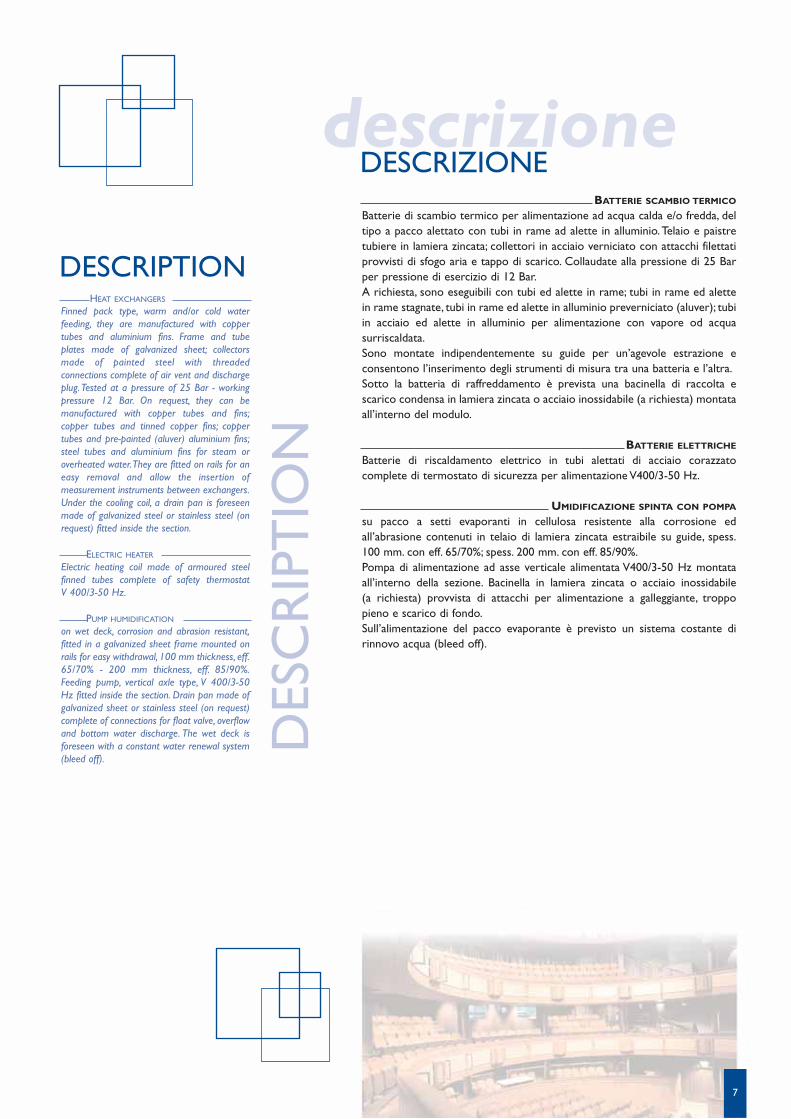
HEAT EXCHANGERS
Finned pack type, warm and/or cold waterfeeding, they are manufactured with coppertubes and aluminium fins. Frame and tubeplates made of galvanized sheet; collectorsmade of painted steel with threadedconnections complete of air vent and dischargeplug. Tested at a pressure of 25 Bar - workingpressure 12 Bar. On request, they can bemanufactured with copper tubes and fins;copper tubes and tinned copper fins; coppertubes and pre-painted (aluver) aluminium fins;steel tubes and aluminium fins for steam oroverheated water. They are fitted on rails for aneasy removal and allow the insertion ofmeasurement instruments between exchangers.Under the cooling coil, a drain pan is foreseenmade of galvanized steel or stainless steel (onrequest) fitted inside the section.
ELECTRIC HEATER
Electric heating coil made of armoured steelfinned tubes complete of safety thermostat V 400/3-50 Hz.
PUMP HUMIDIFICATION
on wet deck, corrosion and abrasion resistant,fitted in a galvanized sheet frame mounted onrails for easy withdrawal, 100 mm thickness, eff.65/70% - 200 mm thickness, eff. 85/90%.Feeding pump, vertical axle type, V 400/3-50Hz fitted inside the section. Drain pan made ofgalvanized sheet or stainless steel (on request)complete of connections for float valve, overflowand bottom water discharge. The wet deck isforeseen with a constant water renewal system(bleed off).
DESCRIPTION
BATTERIE SCAMBIO TERMICO
Batterie di scambio termico per alimentazione ad acqua calda e/o fredda, deltipo a pacco alettato con tubi in rame ad alette in alluminio. Telaio e paistretubiere in lamiera zincata; collettori in acciaio verniciato con attacchi filettatiprovvisti di sfogo aria e tappo di scarico. Collaudate alla pressione di 25 Barper pressione di esercizio di 12 Bar.A richiesta, sono eseguibili con tubi ed alette in rame; tubi in rame ed alettein rame stagnate, tubi in rame ed alette in alluminio preverniciato (aluver); tubiin acciaio ed alette in alluminio per alimentazione con vapore od acquasurriscaldata.Sono montate indipendentemente su guide per un’agevole estrazione econsentono l’inserimento degli strumenti di misura tra una batteria e l’altra.Sotto la batteria di raffreddamento è prevista una bacinella di raccolta escarico condensa in lamiera zincata o acciaio inossidabile (a richiesta) montataall’interno del modulo.
BATTERIE ELETTRICHE
Batterie di riscaldamento elettrico in tubi alettati di acciaio corazzatocomplete di termostato di sicurezza per alimentazione V400/3-50 Hz.
UMIDIFICAZIONE SPINTA CON POMPA
su pacco a setti evaporanti in cellulosa resistente alla corrosione edall’abrasione contenuti in telaio di lamiera zincata estraibile su guide, spess.100 mm. con eff. 65/70%; spess. 200 mm. con eff. 85/90%.Pompa di alimentazione ad asse verticale alimentata V400/3-50 Hz montataall’interno della sezione. Bacinella in lamiera zincata o acciaio inossidabile (a richiesta) provvista di attacchi per alimentazione a galleggiante, troppopieno e scarico di fondo.Sull’alimentazione del pacco evaporante è previsto un sistema costante dirinnovo acqua (bleed off).
7

ADIABATIC WET DECK HUMIDIFICATION
simple or double bank of spray nozzles - eff. 75%or 90%. Water distribution by means of collectorsand pipes made of PVC, self cleaning nozzles madeof nylon. Feeding pump V 400/3-50 Hz. fittedoutside the section. Water trap made of galvanizedsheet or stainless steel (on request) complete ofconnections for float valve, overflow and bottomwater discharge. Interception valves are forecastedfor the feeding of the nozzles pipe and constantwater renewal system.The humidification section is manufactured withdouble chamber with internal skin made ofgalvanized sheet or stainless steel (on request).
ATOMIZED WATER HUMIDIFICATION
supplied with cabinet for the feeding of theatomizing nozzles connected to the demineralisedwater and compressed air net, complete withinterception electric valves, modulating valves,discharge electric valve, pressure regulator, controlpressure switch and pressure gauge. Atomizingnozzles are made of stainless steel AISI 316.
Distribution net for compressed air and water.Water trap made of galvanized sheet or stainlesssteel (on request).
SELF STEAM PRODUCER HUMIDIFICATION
by means of a cylinder boiler with immersedelectrodes contained in a painted metallic casing.Voltage V 400/3-50 Hz with a micro processorcontrol system foreseen for step or continuousregulation. Steam distributor made of stainless steel,Water trap made of stainless steel.
STEAM HUMIDIFICATION
coming from the net and distributed by a stainlesssteel double tube and condensate recovery. Watertrap made of stainless steel.
DROPLETS ELIMINATOR
Multiple pleated type inserted downstream thecooling coils and the humidification system,composed of frame and fins made of galvanizedsheet or, on request, made of aluminium, stainlesssteel or polypropilene.
DESCRIPTIONDESCRIPTION
UMIDIFICAZIONE ADIABATICA
a semplice o doppio banco di ugelli nebulizzatori con eff. 75% o 90%. Distribuzionedell’acqua attraverso collettori e tubazioni in PVC ed ugelli autopulenti in nylon. Pompadi alimentazione V400/3-50 Hz montata all’esterno della sezione. Vasca in lamiera zincatao in acciaio inossidabile (a richiesta) provvista d’attacchi per alimentazione a galleggiante,troppo pieno e scarico di fondo. Sono previste valvole di intercettazionesull’alimentazione delle rampe ugelli e sistema costante di rinnovo acqua (bleed off).La sezione di umidificazione è eseguita in doppia camera con pareti interne in lamierazincata o in acciaio inossidabile (a richiesta).
UMIDIFICAZIONE AD ACQUA ATOMIZZATA
costituita da cabinet di alimentazione degli ugelli atomizzatori collegato alle reti acquademineralizzata ed aria compressa, contenente elettrovalvole di intercettazione, valvolemodulanti, elettrovalvola di scarico, regolatore di pressione, pressostato di controllo emanometri. Ugelli atomizzatori in acciaio inossidabile AISI 316. Reti di distribuzione ariacompressa ed acqua. Bacino di raccolta in lamiera zincata o in acciaio inossidabile (a richiesta).
UMIDIFICAZIONE AD AUTOPRODUZIONE DI VAPORE
ottenuta da cilindro bollitore a più elettrodi immersi nell’acqua contenuto in un armadiometallico verniciato. Funzionamento elettrico per alimentazione V400/3-50Hz, consistema di controllo a microprocessore predisposto per regolazione a gradini o continua.Distributore di vapore in acciaio inossidabile. Bacino di raccolta condensa in acciaioinossidabile.
UMIDIFICAZIONE CON VAPORE
proveniente da rete e distribuito da lancia in acciaio inossidabile a doppio tubo ed arecupero di condensa. Bacino di raccolta in acciaio inossidabile.
SEPARATORI DI GOCCE
Separatori di gocce a più pieghe inseriti a valle delle batterie di raffreddamento e dei sistemidi umidificazione, costituiti da telaio ed alette separatrici in lamiera zincata o, a richiesta,in alluminio, acciaio inossidabile o polipropilene.
DESCRIZIONE
8
9
DATI TECNICIDATI TECNICI
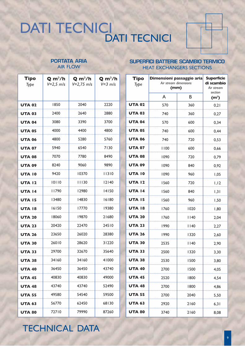
TipoType
UTA 02
UTA 03
UTA 04
UTA 05
UTA 06
UTA 07
UTA 08
UTA 09
UTA 10
UTA 12
UTA 14
UTA 15
UTA 18
UTA 20
UTA 23
UTA 26
UTA 30
UTA 33
UTA 38
UTA 40
UTA 45
UTA 48
UTA 55
UTA 63
UTA 80
Q m3/hV=2,5 m/s
1850
2400
3080
4000
4800
5940
7070
8240
9420
10110
11790
13480
16150
18060
20420
23650
26010
29700
34160
36450
40830
43740
49580
56770
72710
Q m3/hV=2,75 m/s
2040
2640
3390
4400
5280
6540
7780
9060
10370
11130
12980
14830
17770
19870
22470
26020
28620
32670
34160
36450
40830
43740
54540
62450
79990
Q m3/hV=3 m/s
2220
2880
3700
4800
5760
7130
8490
9890
11310
12140
14150
16180
19380
21680
24510
28380
31220
35640
41000
43740
49000
52490
59500
68130
87260
TipoType
UTA 02
UTA 03
UTA 04
UTA 05
UTA 06
UTA 07
UTA 08
UTA 09
UTA 10
UTA 12
UTA 14
UTA 15
UTA 18
UTA 20
UTA 23
UTA 26
UTA 30
UTA 33
UTA 38
UTA 40
UTA 45
UTA 48
UTA 55
UTA 63
UTA 80
570
740
570
740
740
1100
1090
1090
1090
1560
1560
1560
1760
1760
1990
1990
2535
2500
2530
2700
2520
2700
2700
2920
3740
360
360
600
600
720
600
720
840
960
720
840
960
1020
1140
1140
1320
1140
1320
1500
1500
1800
1800
2040
2160
2160
Superficiedi scambio
Air streamsection (m2)
0,21
0,27
0,34
0,44
0,53
0,66
0,79
0,92
1,05
1,12
1,31
1,50
1,80
2,04
2,27
2,60
2,90
3,30
3,80
4,05
4,54
4,86
5,50
6,31
8,08
Dimensioni passaggio ariaAir stream dimensions
(mm)
A B
PORTATA ARIAAIR FLOW
SUPERFICI BATTERIE SCAMBIO TERMICOHEAT EXCHANGERS SECTIONS
TECHNICAL DATA

10
5
7
5
7
7
6
6
6
6
5
5
5
5
4
5
5
4
4
4
5
4
5
5
4
4
6
9
6
9
9
8
8
8
8
6
6
6
6
6
6
6
6
6
6
6
6
6
6
6
6
7
11
7
11
11
10
10
10
10
7
7
7
7
6
7
7
6
6
6
7
6
7
7
6
6
11
16
11
16
16
14
14
14
14
11
11
11
11
10
11
11
10
10
10
11
10
11
11
10
10
15
21
15
21
21
19
19
19
19
15
15
15
14
13
15
15
13
13
13
15
13
15
15
13
13
23
31
23
31
31
28
28
28
28
23
23
23
23
22
23
23
22
22
22
23
22
23
23
22
22
25
32
25
32
32
30
30
30
30
25
25
25
24
22
25
25
22
22
22
25
22
25
25
22
22
38
49
38
49
49
44
44
44
44
38
38
38
36
34
38
38
34
34
34
38
34
38
38
34
34
29
42
29
42
42
34
34
34
34
29
29
29
27
25
29
29
25
25
25
29
25
29
29
25
25
43
50
43
50
50
45
45
45
45
43
43
43
42
41
43
43
41
41
41
43
41
43
43
41
41
22
38
22
38
38
32
32
32
32
22
22
22
20
18
22
22
18
18
18
22
18
22
22
18
18
34
50
34
50
50
43
43
43
43
34
34
34
32
29
34
34
29
29
29
34
29
34
34
29
29
15
30
15
30
30
24
24
24
24
15
15
15
14
13
15
15
13
13
13
15
13
15
15
13
13
21
43
21
43
43
36
36
36
36
21
21
21
19
17
21
21
17
17
17
21
17
21
21
17
17
12
21
12
21
21
18
18
18
18
12
12
12
11
9
12
12
9
9
9
12
9
12
12
9
9
16
28
16
28
28
23
23
23
23
16
16
16
15
14
16
16
14
14
14
16
14
16
16
14
14
UTA 02
UTA 03
UTA 04
UTA 05
UTA 06
UTA 07
UTA 08
UTA 09
UTA 10
UTA 12
UTA 14
UTA 15
UTA 18
UTA 20
UTA 23
UTA 26
UTA 30
UTA 33
UTA 38
UTA 40
UTA 45
UTA 48
UTA 55
UTA 63
UTA 80
63 Hz 125 Hz 250 Hz 500 Hz 1000 Hz 2000 Hz 4000 Hz 8000 Hzlungh. setto
baffle length (mm)lungh. setto
baffle length (mm)lungh. setto
baffle length (mm)llungh. setto
baffle length (mm)lungh. setto
baffle length (mm)lungh. setto
baffle length (mm)lungh. setto
baffle length (mm)lungh. setto
baffle length (mm)
900 1500 900 1500 900 1500 900 1500 900 1500 900 1500 900 1500 900 1500
TipoType
DATI TECNICI / TECHNICAL DATAATTENUAZIONE ACUSTICA - SOUND ATTENUATION
ATTENZIONE: I sopra elencati valori di attenuazione sono da intendersi indi-cativi e basati sulla velocità di attraversamento aria in batteria di 2,5 m/sec.
ATTENTION: Above mentioned values are for reference only and are based onair speed into exchanger V=2,5 m/s.
11
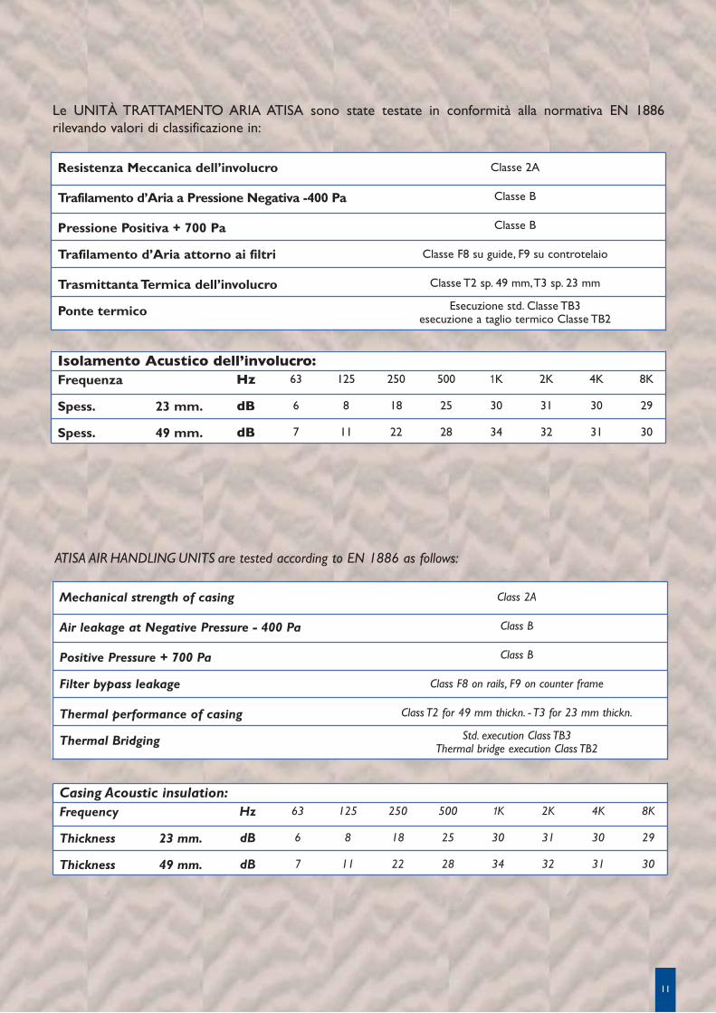
Resistenza Meccanica dell’involucro
Trafilamento d’Aria a Pressione Negativa -400 Pa
Pressione Positiva + 700 Pa
Trafilamento d’Aria attorno ai filtri
Trasmittanta Termica dell’involucro
Ponte termico
Classe 2A
Classe B
Classe B
Classe F8 su guide, F9 su controtelaio
Classe T2 sp. 49 mm, T3 sp. 23 mm
Esecuzione std. Classe TB3esecuzione a taglio termico Classe TB2
Hz
dB
dB
63
6
7
125
8
11
250
18
22
500
25
28
1K
30
34
2K
31
32
4K
30
31
8K
29
30
Isolamento Acustico dell’involucro:Frequenza
Spess.
Spess.
23 mm.
49 mm.
Mechanical strength of casing
Air leakage at Negative Pressure - 400 Pa
Positive Pressure + 700 Pa
Filter bypass leakage
Thermal performance of casing
Thermal Bridging
Class 2A
Class B
Class B
Class F8 on rails, F9 on counter frame
Class T2 for 49 mm thickn. - T3 for 23 mm thickn.
Std. execution Class TB3Thermal bridge execution Class TB2
Hz
dB
dB
63
6
7
125
8
11
250
18
22
500
25
28
1K
30
34
2K
31
32
4K
30
31
8K
29
30
Casing Acoustic insulation:Frequency
Thickness
Thickness
23 mm.
49 mm.
Le UNITÀ TRATTAMENTO ARIA ATISA sono state testate in conformità alla normativa EN 1886 rilevando valori di classificazione in:
ATISA AIR HANDLING UNITS are tested according to EN 1886 as follows:

NOTENOTES
12
NOTENOTES
13

NOTENOTES
14
CERTIFICATICERTIFICATI
CER
TIF
ICA
TES
CER
TIF
ICAT
ES
I dati contenuti nel presente catalogo possono essere cambiati senza obbligo di preavviso.
All specifications are subject to change without notice.

20010 Bareggio (MI) - Via F. Gallina, 51 - Tel. 0039 0290313.1 - Fax 0039 0290361279
16149 Genova - Via De Marini, 1 - Tel. 0039 010640281 - Fax 0039 0106424950
Company qualified ISO 9001:2008 - [email protected] - www.atisa.it
Iscritta presso il Registro Imprese di Milano N. 166298 - P. IVA: 00863300158
REA Milano N. 928822 - Capitale sociale € 2.000.000,00 interamente versato
UTA
04/
11 - C
od.
408 - i.
p.


![[Dai Nippon Books] - [Aero Detail 015] - Macchi c.200_202_205](https://static.fdocumenti.com/doc/165x107/577cc44f1a28aba71198deeb/dai-nippon-books-aero-detail-015-macchi-c200202205.jpg)