Analysis and control of façade claddings structural issues
13
Analysis and control of façade claddings structural issues Angelo Lucchini, Enrico Sergio Mazzucchelli * , Alberto Stefanazzi, Sergio Tattoni Sergio Tattoni DABC - Dipartimento di Architettura, Ingegneria delle Costruzioni e Ambiente Costruito, Politecnico di Milano, via Ponzio 31, Milano, 20133, Italia Alberto Stefanazzi DABC - Dipartimento di Architettura, Ingegneria delle Costruzioni e Ambiente Costruito, Politecnico di Milano, via Ponzio 31, Milano, 20133, Italia Enrico Sergio Mazzucchelli DABC - Dipartimento di Architettura, Ingegneria delle Costruzioni e Ambiente Costruito, Politecnico di Milano, via Ponzio 31, Milano, 20133, Italia Angelo Lucchini DABC - Dipartimento di Architettura, Ingegneria delle Costruzioni e Ambiente Costruito, Politecnico di Milano, via Ponzio 31, Milano, 20133, Italia * Corresponding author Tel.: +39-02-2399-6019; fax: +39-02-2399-6080; e-mail: [email protected] 88 Vol. 3, No. 1 (2017) Highlights Abstract Mechanical safety of façade claddings is of fundamental importance. Overlook or underestimate the structural aspects in the façade design can result in critical consequences. Numerical modelling and laboratory test are necessary to study the structural aspects of façade claddings. The study and design of façades dynamic behaviour is an innovative field of construction engineering. Although closely related with the building structure and required to possess adequate resistance to the acting loads too, the new cladding systems have shown not infrequently inconsistencies or mechanical deficiencies, such as to compromise their safety. The paper shows the necessity of studying and solving the structural aspects of façade claddings through proper numerical modelling and laboratory test, defining a systematic methodology for the evaluation of the structural aspects of the façade cladding that can be used both in case of new construction and building refurbishment. Keywords Façade Cladding, Seismic Behaviour, Wind Action, Laboratory Test, FEM Modelling 1. INTRODUCTION Today’s constructions are mainly built with a reinforced concrete, steel or wood load-bearing structure. The structure is then combined with an opaque envelope able to ensure protection from atmospheric agents and to guarantee the optimal levels of comfort (hygrothermal, acoustic and visual). The continuous development of envelope solutions (both opaque and transparent) and cladding materials has led to a considerable increase of nowadays available technological and technical options, as well as to a wider possibility to choose, case by case, the most appropriate opaque and/or transparent façade system related to the specific case study [1]. On the other hand, a thorough and in-depth design analysis of the solutions to be adopted has become essential. This considering that each solution always has, in
Transcript of Analysis and control of façade claddings structural issues
88
Analysis and control of façade claddings structural issues
Angelo Lucchini, Enrico Sergio Mazzucchelli*,
Alberto Stefanazzi, Sergio Tattoni
Sergio TattoniDABC - Dipartimento di Architettura, Ingegneria delle Costruzioni e Ambiente Costruito, Politecnico di Milano, via Ponzio 31, Milano, 20133, Italia
Alberto StefanazziDABC - Dipartimento di Architettura, Ingegneria delle Costruzioni e Ambiente Costruito, Politecnico di Milano, via Ponzio 31, Milano, 20133, Italia
Enrico Sergio MazzucchelliDABC - Dipartimento di Architettura, Ingegneria delle Costruzioni e Ambiente Costruito, Politecnico di Milano, via Ponzio 31, Milano, 20133, Italia
Angelo LucchiniDABC - Dipartimento di Architettura, Ingegneria delle Costruzioni e Ambiente Costruito, Politecnico di Milano, via Ponzio 31, Milano, 20133, Italia
* Corresponding authorTel.: +39-02-2399-6019;fax: +39-02-2399-6080;e-mail: [email protected]
88
Vol.
3, N
o. 1
(20
17)
Highlights
Abstract
Mechanical safety of façade claddings is of fundamental importance. Overlook or underestimate the structural aspects in the façade design can result in critical consequences. Numerical modelling and laboratory test are necessary to study the structural aspects of façade claddings. The study and design of façades dynamic behaviour is an innovative field of construction engineering.
Although closely related with the building structure and required to possess adequate resistance to the acting loads too, the new cladding systems have shown not infrequently inconsistencies or mechanical deficiencies, such as to compromise their safety. The paper shows the necessity of studying and solving the structural aspects of façade claddings through proper numerical modelling and laboratory test, defining a systematic methodology for the evaluation of the structural aspects of the façade cladding that can be used both in case of new construction and building refurbishment.
Keywords
Façade Cladding, Seismic Behaviour, Wind Action, Laboratory Test, FEM Modelling
1. INTRODUCTION
Today’s constructions are mainly built with a reinforced concrete, steel or wood load-bearing structure. The structure is then combined with an opaque envelope able to ensure protection from atmospheric agents and to guarantee the optimal levels of comfort (hygrothermal, acoustic and visual).The continuous development of envelope solutions (both opaque and transparent) and cladding materials has led to a considerable increase of nowadays available technological and technical options, as well as to a wider possibility to choose, case by case, the most appropriate opaque and/or transparent façade system related to the specific case study [1]. On the other hand, a thorough and in-depth design analysis of the solutions to be adopted has become essential. This considering that each solution always has, in
89
addition to the advantages that justify its choice, possible critical issues that, if not properly considered, can lead to important defects and problems [2].The paper summarizes the main results of a series of analysis activities and FEM (Finite Element Method) modelling, laboratory and on site tests, carried out in order to understand the real behaviour of each element of a façade system and its service limits. These activities were preceded by extensive campaign of investigation and in situ tests for the collection of specific data, necessary to assess the mechanical behaviour of a façade cladding. The goal of the research activities here described has been the definition of a systematic methodology for the evaluation of the structural aspects of façade claddings, valid in case of design of a new cladding solution, as well as in case of evaluation of an already realized façade cladding, but that needs a consolidation and/or a refurbishment activity.
2. OPAQUE ENVELOPES IN MODERN BUILDINGS
Today’s external cladding systems include a wide range of materials [3] [4]. Usually the cladding elements are fixed to a support layer, frequently a masonry wall, by means of adhesives and/or mechanical devices (more or less complex), which are designed and manufactured in order to:• support the own weight of the cladding elements;• adapt to the construction and installation tolerances;• allow the relative movements under the action of thermal and hygrometric
variations;• withstand the wind and seismic actions;• convey the perpendicular, tangential and moment actions to the supporting
structure (and vice versa);• preserve the functionality of the façades over time and allow an easy and
regular maintenance of all the façade components.In this framework, the cladding systems are gaining an increasing importance, especially with regard to: aesthetic appearance, thermal performance and construction modality. The design and construction process of façades, that meets the above described requirements, needs specific skills and experience, as well as high level technological elements and solutions [5] [6]. In this regard, the structural design of a building cannot consider the facades only as a simple “additional mass” and as a means to transfer actions to the structure, as well as the façade design cannot be limited only to the definition of the architectural composition and stratigraphy performance (e.g. thermal and acoustic). As a matter of fact, the “outer skin” is connected to the bearing structure and
1. INTRODUZIONE
Gli edifici odierni sono realizzati nella maggior parte dei casi con struttura portante in cemento armato, acciaio o legno alla quale viene abbinata una chiusura esterna continua in grado di assicurare protezione dagli agenti atmosferici e garantire le migliori condizioni di comfort (igrotermico, acustico, visivo) possibili. La continua evoluzione delle soluzioni di involucro (sia di tipo opaco che trasparente) e dei materiali di rivestimento ha portato ad un notevole incremento delle opzioni tecnologiche e tecniche oggi utilizzabili, così come una maggiore possibilità di procedere, caso per caso, alla scelta e alla definizione della soluzione di facciata opaca e/o trasparente più adeguata allo specifico caso di studio [1]. Per contro, si sta sempre più rafforzando la necessità di dare corso ad una approfondita elaborazione e verifica progettuale delle soluzioni che si intende adottare, nella consapevolezza che ognuna di esse presenta sempre, oltre all’insieme di vantaggi che ne giustificano la scelta, possibili criticità che, se non adeguatamente considerate, possono dare luogo a difetti e inconvenienti anche di grave entità [2]. Il presente contributo raccoglie una sintesi dei risultati di una serie di attività di analisi e modellazione FEM (Finite Element Method), test di laboratorio e in situ realizzati al fine di comprendere l’effettivo funzionamento di ogni singolo elemento di una facciata ed i suoi limiti di servizio. Tali attività sono state precedute da un’ampia campagna di indagini e prove sperimentali in situ per la raccolta di dati specifici necessari alla valutazione del comportamento meccanico di un rivestimento di facciata. L’obiettivo dell’attività di ricerca qui descritta è quello della definizione di una metodologia sistematica per la valutazione degli aspetti strutturali dei rivestimenti di facciata, valida sia in caso di progetto di una nuova soluzione, sia in caso di valutazione di una soluzione già realizzata, ma che necessiti di interventi di consolidamento e/o adeguamento.
2. LE CHIUSURE OPACHE NEGLI EDIFICI MODERNI
I sistemi di rivestimento esterno oggi utilizzabili comprendono una vasta tipologia di materiali [3] [4], che vengono vincolati ad un supporto, frequentemente di tipo murario, tramite collanti e/o apparecchi (più o meno complessi) di vincolo meccanico, i quali vengono progettati e realizzati al fine di:• sostenere il peso proprio degli
elementi di rivestimento;• adattarsi alle loro tolleranze, di
costruzione e di installazione;• consentirne i movimenti relativi,
sotto l’azione di variazioni termiche ed igrometriche;
• sopportare le azioni di vento e sisma;
• convogliare le azioni normali, tangenziali e di momento alla struttura portante (e viceversa);
• conservare la funzionalità delle facciate nel tempo e permetterne una semplice e regolare manutenzione in tutte le loro parti
90
inevitably interacts with it. It is therefore essential that a new opaque façade system does not show any inconsistency or mechanical deficiencies due to the underestimation of the effective behaviour of the whole system (deriving not only from the acting loads but also, for example, from the effects of daily and seasonal thermal and hygrometric variations), that otherwise could lead to endanger its safety and to compromise its service maintenance [2]. On the other hand, the right consideration of mechanical aspects in the design phase allows to choose properly the façade stratigraphy and to arrive to guaranteed and reliable results, with optimized costs from a technical and constructive point of view.The increase of the façades size in modern buildings, especially considering height and/or width, is another factor that may generate cladding structural problems, in particular under the deformability point of view. While below a certain size, determined by the possibility of realization of the concerned object, there are no particular structural problems and may not be needed a specific calculation, beyond a certain size the structural element could be adapted to the requirements only by means of specific calculations or, it could even become not suitable at all. In this case, a different conceptual approach should be followed. Therefore, the question arises whether, for certain types of façade claddings, the point of no return (which is the limit beyond which the realization of a certain element is not appropriate) has already been reached.As an example, the traditional ventilated cladding systems can be considered. These systems are designed for the assembly on a slender substructure, and their intrinsic characteristics do not adapt easily to high thermal insulation thickness, typical of today’s building envelopes. This implies, in fact, the increase of the distance between the cladding surface and the support wall, with a consequent increase of the substructure profiles thickness and sizes, necessary in order to still guarantee an adequate behaviour against ordinary (positive and negative pressures of the wind) and extraordinary actions (horizontal actions related to seismic events), together with the necessary lateral stability. This results in an increase both in the substructure cost and in the amount of material used for the production of the substructure profiles themselves.
3. FAÇADE CLADDINGS AND STRUCTURAL ISSUES
As known, a façade cladding can be subject to many different actions. If we consider the wind action, the most important parameter to be considered is the wind speed, reasonably constant at height, but which undergoes variations as we approach the ground because of the presence of obstacles and roughness
componenti.I sistemi di chiusura stanno inoltre guadagnando un’importanza sempre maggiore per quanto concerne le prestazioni termiche, estetiche e la modalità costruttiva/installativa. La progettazione e la realizzazione di facciate che soddisfino i requisiti sopra elencati necessita di capacità ed esperienza specifiche, così come di elementi e di soluzioni di appropriato livello tecnologico [5] [6]. A tal riguardo, il progetto strutturale dell’edificio non può limitarsi a considerare le facciate come un semplice “carico aggiuntivo” ed un mezzo per il trasferimento di azioni alla struttura, così come il progetto del rivestimento non può limitarsi alla sola definizione del prospetto di facciata, della stratigrafia e delle sue prestazioni termiche ed acustiche. La “pelle di rivestimento esterno” è infatti collegata alla struttura portante e interagisce inevitabilmente con essa. È pertanto fondamentale che i nuovi sistemi di facciata opaca non presentino incongruenze o carenze di natura meccanica dovute alla sottovalutazione del comportamento effettivo e di insieme (derivanti non solo dai carichi agenti ma anche, ad esempio, dagli effetti delle variazioni termiche ed igrometriche giornaliere e stagionali), tali da metterne a rischio la sicurezza e da comprometterne di conseguenza il mantenimento in servizio [2]. Per contro, una adeguata valutazione degli aspetti meccanici nella fase di progettazione consente di mettere correttamente a punto la stratigrafia e di pervenire a risultati sicuri ed affidabili dal punto di vista tecnico, costruttivo ed economico.La tendenza all’incremento della dimensione dei fronti, in altezza e/o larghezza, degli edifici moderni è un ulteriore fattore potenzialmente critico dal punto di vista strutturale, specie per quanto concerne l’aspetto della deformabilità. Mentre al di sotto di una certa dimensione, determinata dalla possibilità di realizzazione dell’elemento in esame, non esistono particolari problemi strutturali e potrebbero non essere necessari calcoli specifici, oltre una determinata dimensione l’elemento strutturale potrebbe essere adattato alle esigenze solamente mediante calcoli specifici, oppure potrebbe divenire addirittura non adatto ed occorrerebbe, pertanto, un differente approccio concettuale. È lecito chiedersi pertanto se, per alcune tipologie di rivestimento di facciata, si sia già arrivati ad un punto di non ritorno, ovvero ad un limite oltre il quale la loro realizzazione e/o applicazione non sia più da ritenersi consona. A titolo esemplificativo si considerino i tradizionali sistemi di rivestimento a parete ventilata, progettati per il montaggio su una sottostruttura snella, che per le loro caratteristiche intrinseche mal si prestano a dialogare con elevati spessori d’isolamento termico, tipici delle odierne chiusure. Ciò comporta, infatti, l’allontanamento del piano del rivestimento da quello della muratura di supporto retrostante, con un conseguente incremento di spessori e dimensioni dei profili della sottostruttura, necessario al fine di continuare a garantire un adeguato comportamento nei confronti di sollecitazioni ordinarie (pressioni positive e negative del vento) e

91
[7]. A fixed, non-deformable body immersed in the wind gives rise to two related effects: on one side, the body changes the airflow, by altering the local configuration; on the other side, on the surface of the body it arises a pressure “P” different from the pressure “P0” of the undisturbed flow. The body surface is thus subjected to an aerodynamic action (p = P-P0), linked to the pressure variation on its surface [7]. The local aerodynamic actions due to the wind on each cladding element can be evaluated considering, among all the possible directions of the wind, those that can cause the most intense actions. Especially near the edges and corners of the building, such actions are often the highest (see fig. 1).
Figure 1. Wind deviation and vortices formation in correspondence of a building (left). Negative wind pressures zones and pressure coefficients on the building façades (right).
Figure 2. Shell thermal insulated envelope detachment due to the wind action (Brescia, 2016).In this case the insulating panels were fixed to the masonry support in a wrong way.
Figure 1 shows the pressure coefficients on the side walls of a building under the wind action. It can be noticed that the negative wind pressure intensity, which acts near the building edges, is significantly higher than the pressure on the windward surface [7]. The stability of a cladding layer depends therefore on the effectiveness of its fixing to the devices and/or support elements and on the connection between the latter and the building structure, otherwise finishing detachments may occur (as shown in fig. 2).
straordinarie (azioni orizzontali legate ad eventi sismici), insieme alla necessaria stabilità laterale: ciò si traduce in un aumento del materiale utilizzato per la produzione dei profili e del costo della sottostruttura stessa.
3. RIVESTIMENTI DI FACCIATA E PROBLEMATICHE DI TIPO STRUTTURALE
Come noto, un rivestimento di facciata può essere soggetto a molteplici azioni. Se si considera l’azione del vento il parametro più importante da tenere in considerazione è la velocità, ragionevolmente costante in quota, ma che subisce significative variazioni nell’approssimarsi a terra a causa della presenza di ostacoli e rugosità [7]. Un corpo fisso, indeformabile, immerso in un flusso d’aria, dà
origine a due effetti correlati: da un lato, il corpo modifica il flusso d’aria stesso, cambiandone la configurazione locale; dall’altro, sulla superficie del corpo si genera una pressione “P” diversa dalla “P0”, pressione del flusso indisturbato. La superficie del corpo viene così sottoposta ad una azione aerodinamica (p = P-P0) legata alla variazione di pressione sulla sua superficie [7]. Le azioni aerodinamiche locali esercitate dal vento sui singoli elementi di un rivestimento di facciata sono valutate considerando, tra tutte le

92
A second important aspect concerns the behaviour of cladding systems in case of earthquake [8].The façades, considered as non-structural elements, have stiffness and strength usually overlooked in the analysis of the seismic response of the building and they are designed to withstand only vertical loads (self-weight), wind and seismic action (that arises from the acceleration of its mass), according to the following formula:
where: • Fa is the horizontal seismic force acting in the element centre of mass and
in the most unfavourable direction [kN]; • Wa is the element weight [kN]; • Sa is the maximum adimensional acceleration to which the structural
element is subjected and it coincides with the limit state under examination; • qa is the structure factor of the element (in case of façades it is considered
qa=2). • γa is the factor of importance, normally equal to 1, but that is taken equal
to 1.5 when there are specific safety problems.
Figure 3. Faculty of Engineering after the 2009 earthquake (Aquila, Italy): wall ejection and collapse of the glass façade on the main front side (left). Industrial building after the 2012 earthquake in Emilia (Italy): facade overturning (right).
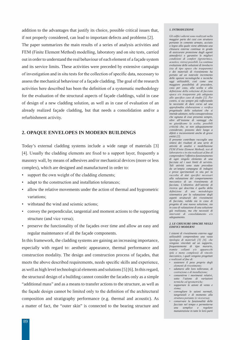
Figure 3 illustrates two examples of façades collapse during the recent seismic events in Italy.The pictures show how the façade elements should be able to absorb, without consequences, also the deformations of a structure subjected to horizontal forces (acting parallel to their plane) due to the wind and, especially, to the earthquake action (fig. 4). In this case, the verification is satisfied if under the action of the loads to the prescribed different limit states, the interstorey drift is not likely to cause
possibili direzioni del vento, quelle che provocano le azioni più intense. Soprattutto in prossimità di bordi e spigoli degli edifici, tali azioni sono spesso le più elevate (fig. 1).La figura 01 mostra i coefficienti di pressione sulle pareti laterali di un edificio investito dal vento dove si può constatare che l’intensità della depressione che agisce in prossimità degli spigoli è molto maggiore della pressione sulla parte investita direttamente [7]. La stabilità di uno strato di rivestimento dipende quindi dall’efficacia del suo vincolo agli strati e/o elementi di supporto e dei collegamenti di questi ultimi alla struttura dell’edificio. In caso contrario possono verificarsi distacchi (come quello rappresentato in fig. 2).Un secondo aspetto fondamentale riguarda il comportamento dei sistemi di rivestimento in caso di sisma [8]. Le facciate, considerate come elementi non strutturali, presentano rigidità e resistenza di solito trascurate nell’analisi della risposta sismica di un edificio e sono progettate per sopportare solamente i carichi verticali (peso proprio), l’azione del vento e l’azione sismica che nasce dall’accelerazione della propria massa:
Fa = [(Sa x Wa)/qa] x γa
dove: • Fa è la forza sismica orizzontale
agente nel centro di massa dell’elemento nella direzione più sfavorevole [kN];
• Wa è il peso dell’elemento [kN];
• Sa è l’accelerazione massima adimensionalizzata che subisce l’elemento strutturale e corrisponde allo stato limite in esame;
• qa è il fattore di struttura dell’elemento (nel caso di facciate si considera qa=2).
• γa è il fattore di importanza, normalmente uguale a 1, ma che sarà preso pari a 1,5 nei casi in cui siano presenti problemi particolari di sicurezza.
Nella figura 03 sono rappresentati esempi di crolli di facciate a seguito di recenti eventi sismici in Italia. Essi mostrano come gli elementi di facciata debbano essere in grado di
93
Figure 4. Movement possibility of a glazed panel with elastic sealant.
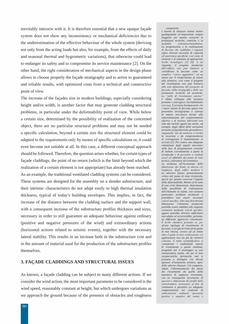
Figure 5. Induced stress on façade panelling due to the “drift” effect, related to panels position, and fastening type.
damage on the façades; or, if designed and built with parts/elements that can be sacrificed, the façades are able to absorb higher floor displacements and they are easily replaceable, in order to restore in a short time and at low cost the integrity of the façades themselves after exceptional intensity events. In more detail, an earthquake causes building horizontal movement. The resulting inertial forces are supported by the main structural elements (pillars, beams, floors, stairs bodies), but also everything that is within the building is subject to these inertial forces. The higher inertial forces are located in the upper part of the building, where the displacement is maximum. They act as a pressure (or negative pressure) normal to the surface of the façade cladding.
assorbire senza conseguenze anche le deformazioni della struttura sottoposta alle forze orizzontali agenti parallelamente al loro piano dovute al vento e, soprattutto al sisma (fig. 4). La verifica è soddisfatta se sotto l’azione dei carichi interessati ai vari stati limite prescritti, lo spostamento (drift) di interpiano non è tale da provocare danni sulle facciate; oppure se le medesime siano state progettate e realizzate con parti/elementi sacrificabili, in grado di assorbire anche elevati spostamenti di piano, e facilmente sostituibili per poter ristabilire, in tempi brevi e a basso costo, l’integrità della facciata a seguito di eventi di eccezionale intensità. Nel dettaglio, un sisma provoca movimenti orizzontali nell’edificio. Le forze inerziali risultanti sono supportate

94
The maximum drift (differential displacement between two floors) occurs in the lower part of a building and it causes alternating shearing forces (see fig. 05) in the non-structural element parallel to the movement direction (e.g. on external walls and partitions). These movements are not compatible, for example, with façades that involve the use of “fragile” materials, such as, natural stones, ceramic tiles, glass, etc. The safety assessment requires the calculation of the maximum displacement of the specific system under seismic loads, but both the Italian Technical Code NTC 2008 and Eurocode 8 [9] [10], admit that is enough to limit the drift (dr) to values as a function of the inter-floor height (h). For external walls rigidly connected to the structure and that can interfere with the deformability of the structure itself, the drift value is dr <0.005 * h. For walls designed so as not to suffer damage as a result of inter-floor drift (because of their intrinsic deformability or because of the deformability of the connections to the structure), it is considered dr <0.01 * h. Panels (or slabs), mullions and transoms of façades must therefore be calculated and checked both under deformation and forces parallel to their plane (drift) and for those (wind, earthquake) acting perpendicular to the same plane. This in order to avoid the damage propagation through the building cladding system. In particular, it is necessary to consider that the fasteners of the façade elements on the supporting walls are generally subjected to combined actions (compression, traction, shear and moment). The control of the mechanical strength must be done by calculating the real interaction between the fastener and the wall itself [11].A further aspect that influences the mechanical safety of façade claddings is closely related to the differential dimensional variations due to the cycles of humidity and temperature changes, unfortunately today not enough taken into account in the design phase, also because of a non-exhaustive specific legislation on this topic. The humidity variation cycles mainly concern porous materials, while those of temperature include all kinds of material. Seldom the façade materials and products suppliers provide full information about these aspects. In this regard, the use of different cladding materials, with their specific connection and fixing techniques, can easily generate critical stress states in today’s building façades, resulting from differential deformations, free or imposed. The thermal expansion coefficient is known for many construction materials. It is highly variable from material to material and it can cause dimensional incompatibility between different materials coupled together (e.g. concrete-aluminium alloy, steel-wood, etc.). For many other materials, such as those used as insulation or as adhesive, this coefficient is not known at all. In this regard, the NTC [9] can be considered a valid
dai principali elementi strutturali (pilastri, travi, solai, corpi scale), ma anche tutto ciò che è contenuto nella costruzione è soggetto a tali forze. Le forze inerziali più elevate si avranno nella parte superiore dell’edificio, in cui lo spostamento è massimo; esse agiscono come una pressione (o depressione) normale alla superficie del rivestimento di facciata. Il massimo spostamento di piano (drift) si verifica invece nella parte inferiore dell’edificio ed induce negli elementi non strutturali disposti parallelamente alla direzione del moto (quali chiusure e partizioni) sollecitazioni di scorrimento alternate (fig. 5), non compatibili, ad esempio, con facciate che prevedono l’impiego di materiali “fragili” quali piastrelle ceramiche, vetro, etc. La valutazione della sicurezza richiede il calcolo del massimo spostamento del sistema specifico sotto l’azione di carichi sismici, ma sia il codice italiano NTC 2008 che l’Eurocodice 8 [9] [10], considerano sufficiente limitare il drift a valori in funzione dell’altezza interpiano (h). Per pareti esterne collegate rigidamente alla struttura e che interferiscono con la deformabilità della stessa struttura il valore di drift è dr <0,005 * h, mentre per pareti progettate in modo da non subire danni causati dal drift di interpiano, a seguito della loro deformabilità intrinseca o deformabilità delle connessioni con la struttura, si considera dr <0,01 * h. Pannelli (o lastre), montanti e traversi di supporto delle facciate devono essere pertanto calcolati e verificati sia sotto deformazione e forze agenti parallele al loro piano (drift), sia per quelle perpendicolari al piano stesso (vento, sisma), ciò al fine di evitare l’innesco e propagazione di danni a carico del rivestimento. In particolare occorre considerare che i dispositivi di fissaggio degli elementi di facciata alle pareti di supporto sono generalmente sottoposti ad azioni combinate (compressione, trazione, taglio e momento) e la verifica deve essere pertanto effettuata calcolando l’interazione tra il fissaggio ed il materiale costituente il supporto stesso [11].Un ulteriore aspetto che influenza la sicurezza meccanica dei rivestimenti di facciata è strettamente correlato ai cicli di variazione di umidità e di temperatura, purtroppo ancora oggi poco considerati, forse anche a causa di una non esaustiva richiesta normativa specifica a riguardo. I cicli di variazione di umidità riguardano principalmente i materiali particolarmente porosi, mentre quelli di temperatura comprendono tutti i tipi di materiale. Assai di rado i fornitori di materiali e prodotti di rivestimento di facciata forniscono informazioni esaurienti su questi aspetti. L’utilizzo di differenti materiali di rivestimento, con le relative tecniche di collegamento e fissaggio, nelle facciate odierne può facilmente generare stati tensionali critici conseguenti a deformazioni differenziali, libere o imposte. Il coefficiente di dilatazione termica è noto per la maggior parte dei materiali da costruzione ed è assai variabile da materiale a materiale: ciò può causare una incompatibilità dimensionale tra differenti materiali tra loro accoppiati (ad esempio cemento-alluminio,

95
design support as they indicate the outside air temperature ranges to be used in computing the response of structures to thermal actions (in the absence of more precise measurements). These indications can also be extended to the evaluation of the thermal behaviour of the facade cladding components.
4. METHODOLOGY, CASE STUDIES ANALYSIS AND RE-
SULTS DISCUSSION
If not properly considered, the structural aspects highlighted in the previous paragraph 3, may arise in serious problems related to the mechanical safety of cladding systems. These cases can be essentially classified in two main categories: analysis of an existing cladding system and new cladding system design.In the first case the set of analysis and test activities can be summarized in: possible in situ tests, determination of the characteristics of the façade system materials, FEM modelling, validation of the FEM model by means of experimental tests, development of solutions able to implement the cladding solution deficit, testing of the developed solution.In case of a new cladding system design the set of analysis and test activities can be summarized in: evaluation of the characteristics of the façade system materials, FEM modelling, validation of the FEM model by means of experimental tests on mock-up of the façade, with possible process iteration in case of unsatisfactory results.This methodology has been applied to some case studies, including the two below described.The first example is a construction with a shell thermal insulated envelope with a clinker strips finishing. This specific solution requires the use of a strong thermal insulation, e.g. foamglass, able to support the weight of the coating and to absorb the stress due to wind and earthquake actions, as well as dimensional variations related to cycles of humidity and temperature changes. The weight and the forces acting on the insulating panel can cause a cyclic stress state that can lead to the thermal panel breaking, causing the collapse of the coating (see. fig. 6). The assessment of the stratigraphy behaviour was based on research and on-site test, FEM linear and non-linear modelling (Finite Element Method) under different action combinations related to: own weight, temperature and humidity changes, variations in wind positive/negative pressure. This has been integrated by laboratory tests, performed at the ITC CNR (Istituto per le Tecnologie della Costruzione del Consiglio Nazionale delle Ricerche - San
acciaio-legno, etc.). Per molti altri materiali, quali ad esempio quelli utilizzati come isolanti termici o come adesivo, tale coefficiente non è affatto noto. A tal riguardo, le NTC [9] possono essere considerate un valido supporto progettuale in quanto indicano degli intervalli di temperature per l’aria esterna da utilizzare nel calcolo della risposta di strutture soggette a variazioni termiche (in assenza di misurazioni più precise). Tali indicazioni possono essere estese anche alla valutazione del comportamento termico dei componenti dei rivestimenti di facciata.
4. METODOLOGIA, CASI DI STUDIO E DISCUSSIONE DEI RISULTATI
Se non opportunamente valutati, gli aspetti di tipo strutturale evidenziati nel precedente paragrafo 3, possono manifestarsi in gravi problemi legati alla sicurezza meccanica dei sistemi di rivestimento. I casi che si possono presentare sono essenzialmente riconducibili a due categorie principali: analisi di un sistema di rivestimento esistente e progettazione di un nuovo sistema di rivestimento. Nel primo caso l’insieme delle attività di analisi e test è riassumibile in: eventuali test in situ, determinazione delle caratteristiche dei materiali del sistema di facciata, modellazione FEM, validazione del modello FEM tramite test sperimentali, sviluppo di soluzione in grado di implementare i deficit manifestatisi della soluzione di rivestimento, test di verifica della soluzione sviluppata.Nel caso di progettazione di un nuovo sistema di rivestimento le attività sono invece riassumibili in: valutazione delle caratteristiche dei materiali del sistema di facciata, modellazione FEM, validazione del modello FEM tramite test sperimentali su mock up di facciata, con eventuale iterazione del processo in caso di risultati non soddisfacenti.Tale metodologia è stata applicata ad alcuni casi di studio, tra cui i due qui di seguito descritti. Il primo caso di studio riguarda un rivestimento con un isolamento termico ad alte prestazioni di tipo a cappotto rivestito con tradizionali listelli in clincher. Ciò richiede l’impiego di un isolante robusto, ad esempio il vetro cellulare, in grado di sostenere il peso del rivestimento e di assorbire le sollecitazioni dovute a vento, sisma e variazioni dimensionali. Il peso e le sollecitazioni a carico del pannello isolante possono indurre uno stato tensionale ciclico che può portare addirittura alla rottura del pannello stesso, causando il collasso del rivestimento (v. ad esempio fig. 6).La valutazione del comportamento della stratigrafia del rivestimento si è basata su indagini e test sul posto, modellazione FEM (Finite Element Method) lineare e non lineare sotto le combinazioni di azioni derivanti dai pesi propri, variazioni di temperatura e di umidità, variazioni della pressione/depressione del vento, corredata da prove di laboratorio sulla caratterizzazione dei materiali costituenti la stratigrafia stessa eseguite presso l’ITC CNR (Istituto per le Tecnologie della Costruzione del Consiglio Nazionale delle Ricerche)
96
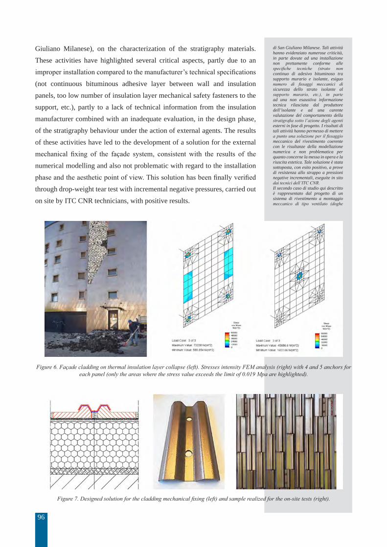
Giuliano Milanese), on the characterization of the stratigraphy materials. These activities have highlighted several critical aspects, partly due to an improper installation compared to the manufacturer’s technical specifications (not continuous bituminous adhesive layer between wall and insulation panels, too low number of insulation layer mechanical safety fasteners to the support, etc.), partly to a lack of technical information from the insulation manufacturer combined with an inadequate evaluation, in the design phase, of the stratigraphy behaviour under the action of external agents. The results of these activities have led to the development of a solution for the external mechanical fixing of the façade system, consistent with the results of the numerical modelling and also not problematic with regard to the installation phase and the aesthetic point of view. This solution has been finally verified through drop-weight tear test with incremental negative pressures, carried out on site by ITC CNR technicians, with positive results.
Figure 6. Façade cladding on thermal insulation layer collapse (left). Stresses intensity FEM analysis (right) with 4 and 5 anchors for each panel (only the areas where the stress value exceeds the limit of 0.019 Mpa are highlighted).
Figure 7. Designed solution for the cladding mechanical fixing (left) and sample realized for the on-site tests (right).
di San Giuliano Milanese. Tali attività hanno evidenziato numerose criticità, in parte dovute ad una installazione non prettamente conforme alle specifiche tecniche (strato non continuo di adesivo bituminoso tra supporto murario e isolante, esiguo numero di fissaggi meccanici di sicurezza dello strato isolante al supporto murario, etc.), in parte ad una non esaustiva informazione tecnica rilasciata dal produttore dell’isolante e ad una carente valutazione del comportamento della stratigrafia sotto l’azione degli agenti esterni in fase di progetto. I risultati di tali attività hanno permesso di mettere a punto una soluzione per il fissaggio meccanico del rivestimento coerente con le risultanze della modellazione numerica e non problematica per quanto concerne la messa in opera e la riuscita estetica. Tale soluzione è stata sottoposta, con esito positivo, a prove di resistenza allo strappo a pressioni negative incrementali, eseguite in sito dai tecnici dell’ITC CNR.Il secondo caso di studio qui descritto è rappresentato dal progetto di un sistema di rivestimento a montaggio meccanico di tipo ventilato (doghe
97
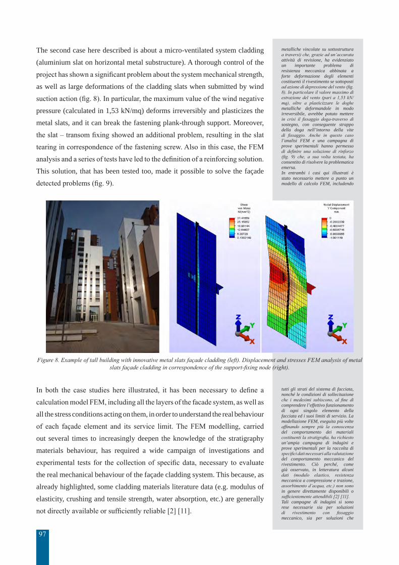
The second case here described is about a micro-ventilated system cladding (aluminium slat on horizontal metal substructure). A thorough control of the project has shown a significant problem about the system mechanical strength, as well as large deformations of the cladding slats when submitted by wind suction action (fig. 8). In particular, the maximum value of the wind negative pressure (calculated in 1,53 kN/mq) deforms irreversibly and plasticizes the metal slats, and it can break the fastening plank-through support. Moreover, the slat – transom fixing showed an additional problem, resulting in the slat tearing in correspondence of the fastening screw. Also in this case, the FEM analysis and a series of tests have led to the definition of a reinforcing solution. This solution, that has been tested too, made it possible to solve the façade detected problems (fig. 9).
Figure 8. Example of tall building with innovative metal slats façade cladding (left). Displacement and stresses FEM analysis of metal slats façade cladding in correspondence of the support-fixing node (right).
In both the case studies here illustrated, it has been necessary to define a calculation model FEM, including all the layers of the facade system, as well as all the stress conditions acting on them, in order to understand the real behaviour of each façade element and its service limit. The FEM modelling, carried out several times to increasingly deepen the knowledge of the stratigraphy materials behaviour, has required a wide campaign of investigations and experimental tests for the collection of specific data, necessary to evaluate the real mechanical behaviour of the façade cladding system. This because, as already highlighted, some cladding materials literature data (e.g. modulus of elasticity, crushing and tensile strength, water absorption, etc.) are generally not directly available or sufficiently reliable [2] [11].
metalliche vincolate su sottostruttura a traversi) che, grazie ad un’accurata attività di revisione, ha evidenziato un importante problema di resistenza meccanica abbinata a forte deformazione degli elementi costituenti il rivestimento se sottoposti ad azione di depressione del vento (fig. 8). In particolare il valore massimo di estrazione del vento (pari a 1,53 kN/mq), oltre a plasticizzare le doghe metalliche deformandole in modo irreversibile, avrebbe potuto mettere in crisi il fissaggio doga-traverso di sostegno, con conseguente strappo della doga nell’intorno della vite di fissaggio. Anche in questo caso l’analisi FEM e una campagna di prove sperimentali hanno permesso di definire una soluzione di rinforzo (fig. 9) che, a sua volta testata, ha consentito di risolvere la problematica emersa.In entrambi i casi qui illustrati è stato necessario mettere a punto un modello di calcolo FEM, includendo
tutti gli strati del sistema di facciata, nonché le condizioni di sollecitazione che i medesimi subiscono, al fine di comprendere l’effettivo funzionamento di ogni singolo elemento della facciata ed i suoi limiti di servizio. La modellazione FEM, eseguita più volte affinando sempre più la conoscenza del comportamento dei materiali costituenti la stratigrafia, ha richiesto un’ampia campagna di indagini e prove sperimentali per la raccolta di specifici dati necessari alla valutazione del comportamento meccanico del rivestimento. Ciò perché, come già osservato, in letteratura alcuni dati (modulo elastico, resistenza meccanica a compressione e trazione, assorbimento d’acqua, etc.) non sono in genere direttamente disponibili o sufficientemente attendibili [2] [11]. Tali campagne di indagini si sono rese necessarie sia per soluzioni di rivestimento con fissaggio meccanico, sia per soluzioni che

98
Such campaigns of investigations were necessary both for cladding solutions with mechanical fastening and for solutions with more traditional connections (e.g. adhesives and mortars). In both cases, the activities had to deal with the problem of: data collection, control of the accuracy of the cladding stratigraphy and choice of the most appropriate modelling tools. Generally, after defining the calculation model and simulating the behaviour of the cladding under the action of external forces, it is necessary to proceed with laboratory test with real scale elements, in order to establish the real behaviour of the cladding system. This helps on one side to check whether the FEM model well represents the real cladding behaviour, on the other to identify a unique and scientifically valid approach to create models that well represent and simulate the behaviour of a cladding system and that, at the same time, are useful to define solutions that can ensure its mechanical safety.
Figure 9. Reinforcing screw position in relation to the T profile axis (left). Displacement and stresses laboratory test of metal slats façade cladding to validate FEM model (right).
Figure 10. Panel-frame connections modelling by means of equivalent springs (D3.2 - Part 3: Connections of sandwich panels. Easie Deliverable of the project, May 2011).
prevedono l’impiego di collegamenti più tradizionali (collanti e malte). In entrambi i casi si è dovuto affrontare il problema della raccolta dei dati, della verifica della correttezza della stratigrafia di rivestimento e della scelta dei più appropriati strumenti per la modellazione. In linea generale, dopo aver definito il modello di calcolo e simulato il comportamento del rivestimento sollecitato da agenti e/o azioni esterne, è opportuno quindi procedere con delle prove di laboratorio su elementi a scala reale per constatare il comportamento effettivo del rivestimento stesso. Questo serve da un lato per verificare se il modello FEM ben rappresenta il reale comportamento del rivestimento, dall’altro per identificare una strada univoca e scientificamente valida per realizzare modelli che ben rappresentino e simulino il comportamento di un rivestimento e come tali utili a definire gli accorgimenti necessari alla sua sicurezza meccanica. Inoltre, la modellazione FEM riveste un ruolo ancora più importante nel caso in cui
99
In addition, the FEM modelling plays an even more important role where the façade panelling cooperates with the load-bearing structure (such as in reinforced concrete industrial buildings or steel structures). In this case, consciously or not, various stabilizing effects can be obtained, among which: individual components (such as beams, pillars) lateral displacement limitation and increase of the buckling strength, local and global, of the structures (acting the façade panels as a diaphragm). In this case, it is also necessary to model the panel-structure connection considering springs with appropriate stiffness, as shown in fig. 10.
5. CONCLUSIONS
The paper shows how the theme of mechanical safety of façade claddings is of fundamental importance, especially in case of complex buildings, but to date not adequately investigated. It concerns the design, control and specific numerical modelling of a façade solution during the project process, considering the deformation regimes and the consequent stress states, both with mechanical connections and traditional ones (e.g. mortars and adhesives), or even mixed-type. The paper, after analysing the results of recent research activities on real case studies, focuses on how such modelling should be based on characteristic data (collected from specific laboratory or on site tests) of materials and elements, usually not available in the current literature, but nevertheless essential to model the mechanical behaviour of a façade in the most realistic way. This opens the way to an essential and innovative field of the construction engineering, specifically dedicated to the study, design and resolution of the dynamic behaviour of façade solutions through an appropriate functional and numerical modelling, supported by experimental tests for the characterization of the materials and for the adjustment of forecasting models.
[1] Lucchini Angelo, Mazzucchelli Enrico Sergio, 2003. L’evoluzione dell’involucro verticale opaco degli edifici. Abitare il futuro – Innovazione Tecnologia Architettura. Milano: BE-MA Editrice, 2003, pp. 168-177.
[2] Lucchini Angelo, Mazzucchelli Enrico Sergio, Stefanazzi Alberto, Tattoni Sergio, 2016. Aspetti strutturali dei rivestimenti di facciata. Convegno Colloquiate 2016, Matera, 12-15 ottobre 2016.
[3] Lucchini Angelo, 2013. Pareti ventilate ad alte prestazioni. Cesano Boscone: Rockwool Italia S.p.A., 2013, 152 p.
[4] Mazzucchelli Enrico Sergio, 2013. Edifici ad energia quasi zero – Materiali, tecnologie e strategie progettuali per involucri e impianti innovativi ad alte prestazioni. Santarcangelo di Romagna: Maggioli Editore, 2013, 320 p.
[5] Watts Adrian, 2011. Modern Construction Envelopes. Vienna: SpringerWienNewYork, 2011, 522 p.
[6] Rigone Paolo, 2011. Le facciate continue – La manutenzione dell’involucro edilizio
6. REFERENCES
la pannellatura di facciata collabori con la struttura portante (come ad esempio nel caso dei capannoni industriali in calcestruzzo armato o nelle strutture metalliche) ottenendo così, consapevolmente o meno, diversi effetti stabilizzanti tra cui: la limitazione dello spostamento laterale dei singoli componenti (ad esempio travi, pilastri) e l’incremento della resistenza all’instabilità locale e globale delle strutture, agendo come diaframma. In tal caso è necessario modellare anche la connessione pannello-struttura a mezzo di molle di opportuna rigidezza, come indicato nella fig. 10.
5.CONCLUSIONI
Il tema della sicurezza meccanica dei rivestimenti di facciata va assumendo una importanza sempre più rilevante, specie nel caso di edifici complessi, ma ad oggi non viene adeguatamente trattato. Esso riguarda il dimensionamento e la verifica delle soluzioni in progetto anche in relazione ai regimi deformativi ed ai conseguenti stati tensionali (sia che i vincoli di posa siano di tipo meccanico che di tipo tradizionale con malte e collanti, o anche di tipo misto) con l’ausilio di opportune modellazioni numeriche. Il presente contributo, basato sui risultati ottenuti in recenti attività di analisi e ricerca su casi di studio, ha focalizzato come tali modellazioni si debbano basare su dati caratteristici dei materiali e degli elementi previsti ricavati da prove e test di laboratorio “ad hoc”, in genere non reperibili in letteratura, ma tuttavia indispensabili per modellare, nel modo più verosimile, il comportamento meccanico, singolo e di insieme, di una stratigrafia di facciata. Ciò apre il campo ad una essenziale ed innovativa branca dell’ingegneria edile, specificamente dedicata allo studio ed alla risoluzione progettuale del comportamento dinamico delle soluzioni di facciata, attraverso apposite modellazioni, funzionali e numeriche, supportate da test sperimentali indispensabili per la caratterizzazione dei materiali da impiegare e per la taratura dei modelli previsionali.

100
vetrato. Santarcangelo di Romagna: Maggioli Editore, 2011, 150 p.[7] CNR – DT – 207/2008 – Istruzioni per la valutazione delle azioni e degli effetti del vento
sulle costruzioni.[8] Lucchini Angelo, Parisi Maria Adelaide, Stefanazzi Alberto, 2013. Seismic behaviour of
building façades. International Journal Of Housing Science, 2013, vol. 37, pp. 1-10.[9] D.M. 14/01/2008 – Norme Tecniche per le Costruzioni.[10] Eurocodice 8 – Progettazione delle strutture per la resistenza sismica.[11] Luca Ahmed Abdou Elsayed, Pietro Fugazzola, “Analisi del comportamento meccanico
delle strutture di facciate innovative”, Politecnico di Milano, Tesi di Laurea Magistrale in Ingegneria dei Sistemi Edilizi, relatore prof. S, Tattoni, aprile 2017.
TEM
A:
Tech
nolo
gies
Eng
inee
ring
Mat
eria
ls A
rchi
tect
ure
Vol.
3, N
o. 1
(20
17)