Alimentatore monofase dal prezzo conveniente. Ingresso ... · 12/12/2001 · Grazie a questa...
35
1 Nuovo prodotto Alimentatore switching S8VK-C (modelli da 60/120/240/480 W) Alimentatore monofase dal prezzo conveniente. Ingresso universale e standard di sicurezza per tutte le applicazioni. Design compatto per un ingombro minimo • Ingresso universale per tutte le applicazioni: 100… 240 Vc.a. (85… 264 Vc.a.) • Ingresso: 90… 350 Vc.c. • Campo di temperature di esercizio: –25… 60°C • Design compatto per l’utilizzo in spazi ridotti • Installazione flessibile tramite le speciali staffe di montaggio • Norme di sicurezza: UL508/60950-1, CSA C22.2 N. 107.1/60950-1 EN50178 (=VDE0160), EN60950-1 (=VDE0805) • EMS: in conformità a EN61204-3 EMI: EN55011 classe A Modelli disponibili Legenda codice modello Nota: non tutte le combinazioni sono possibili. Vedere l’elenco dei modelli nella sezione Informazioni per l’ordine seguente. Informazioni per l’ordine Nota: Per informazioni dettagliate sui modelli standard, rivolgersi all’ufficio OMRON di zona. ! Fare riferimento alle Precauzioni per la sicurezza per tutti gli alimentatori e alle Precauzioni per la sicurezza a pagina 11. 1 2 S8VK-C @@@ 24 1. Potenza 060: 60 W 120: 120 W 240: 240 W 480: 480 W 2. Tensione di uscita 24: 24 V Potenza Tensione di ingresso Tensione di uscita Corrente in uscita Modello 60 W Monofase 100… 240 Vc.a. 90… 350 Vc.c. 24 V 2,5 A S8VK-C06024 120 W 24 V 5 A S8VK-C12024 240 W 24 V 10 A S8VK-C24024 480 W 24 V 20 A S8VK-C48024
Transcript of Alimentatore monofase dal prezzo conveniente. Ingresso ... · 12/12/2001 · Grazie a questa...

1
Nuovo prodotto
Alimentatore switching
S8VK-C (modelli da 60/120/240/480 W)Alimentatore monofase dal prezzo conveniente. Ingresso universale e standard di sicurezza per tutte le applicazioni. Design compatto per un ingombro minimo • Ingresso universale per tutte le applicazioni:
100… 240 Vc.a. (85… 264 Vc.a.)• Ingresso: 90… 350 Vc.c.• Campo di temperature di esercizio: –25… 60°C• Design compatto per l’utilizzo in spazi ridotti• Installazione flessibile tramite le speciali staffe di montaggio• Norme di sicurezza:
UL508/60950-1, CSA C22.2 N. 107.1/60950-1EN50178 (=VDE0160), EN60950-1 (=VDE0805)
• EMS: in conformità a EN61204-3 EMI: EN55011 classe A
Modelli disponibiliLegenda codice modelloNota: non tutte le combinazioni sono possibili. Vedere l’elenco dei modelli nella sezione Informazioni per l’ordine seguente.
Informazioni per l’ordineNota: Per informazioni dettagliate sui modelli standard, rivolgersi all’ufficio OMRON di zona.
! Fare riferimento alle Precauzioni per la sicurezza per tutti gli alimentatori e alle Precauzioni per la sicurezza a pagina 11.
1 2S8VK-C @@@ 24
1. Potenza060: 60 W120: 120 W240: 240 W480: 480 W
2. Tensione di uscita24: 24 V
Potenza Tensione di ingresso Tensione di uscita Corrente in uscita Modello
60 W
Monofase 100… 240 Vc.a. 90… 350 Vc.c.
24 V 2,5 A S8VK-C06024
120 W 24 V 5 A S8VK-C12024
240 W 24 V 10 A S8VK-C24024480 W 24 V 20 A S8VK-C48024

S8VK-C
2
CaratteristicheValori nominali, caratteristiche e funzioni
*1. Non utilizzare un’uscita dell’inverter per l’alimentatore. Sono disponibili inverter con una frequenza di uscita di 50/60 Hz, ma il rialzo della temperatura interna dell’alimentatore potrebbe provocare scintille o combustione.
*2. Per l’avvio a freddo a 25°C. Per informazioni dettagliate, vedere la sezione Curve caratteristiche a pagina 5.*3. Se il regolatore della tensione di uscita (V.ADJ) viene ruotato, la tensione aumenta di più del +15% dell’intervallo di regolazione della tensione
consentito. Per regolare la tensione di uscita, occorre confermare la tensione di uscita effettiva dell’alimentatore e verificare che il carico non sia danneggiato.
*4. Una caratteristica quando la temperatura ambiente di funzionamento è compresa –25… 60°C.*5. Per ripristinare la protezione, togliere l’alimentazione per almeno 3 min, quindi riattivarla.*6. Il conseguimento della certificazione per i modelli da 90… 350 Vc.c. è previsto per giugno 2013.
Potenza 60 W 120 W 240 W 480 W
Caratteristiche Tensione di uscita 24 V 24 V 24 V 24 V
Efficienza (tipica) Ingresso 230 Vc.a. 88% 89% 89% 92%
Ingresso
Tensione*1 100… 240 Vc.a., 90… 350 Vc.c. (campo consentito: 85… 264 Vc.a.)*6
Frequenza*1 50/60 Hz (47… 450 Hz)
Corrente (tipica)Ingresso 115 Vc.a. 1,0 A 2,0 A 2,5 A 4,8 A
Ingresso 230 Vc.a. 0,7 A 1,4 A 1,3 A 2,4 A
Fattore di potenza (tipico) Ingresso 230 Vc.a. 0,44 0,45 0,92 0,97
Emissioni delle correnti armoniche --- Conforme a EN61000-3-2
Corrente di dispersione (tipica)
Ingresso 115 Vc.a. 0,19 mA 0,19 mA 0,24 mA 0,26 mA
Ingresso 230 Vc.a. 0,34 mA 0,36 mA 0,54 mA 0,65 mA
Corrente di spunto (tipica)*2
Ingresso 115 Vc.a. 16 A
Ingresso 230 Vc.a. 32 A
Uscita
Intervallo di regolazione della tensione*3 –10… 15% (tramite regolatori di tensione V.ADJ) (garantito)
Ondulazione a 20 MHz (tipica)*4 Ingresso 230 Vc.a. 70 mV 120 mV 70 mV 130 mV
Stabilità verso la linea 0,5% max. (ingresso 85… 264 Vc.a., 100% di carico)
Stabilità verso l’uscita(tensione di ingresso nominale) 1,5% max., 0… 100% di carico
Coefficiente di temperatura 0,05%/°C max.
Tempo di avvio (tipico)*2
Ingresso 115 Vc.a. 530 ms 720 ms 790 ms 770 ms
Ingresso 230 Vc.a. 410 ms 510 ms 750 ms 670 ms
Tempo di mantenimento (tipico)*2
Ingresso 115 Vc.a. 24 ms 27 ms 34 ms 21 ms
Ingresso 230 Vc.a. 117 ms 128 ms 36 ms 22 ms
Funzioniaggiuntive
Protezione da sovraccarico*2 105… 160% della corrente nominale di carico
Protezione da sovratensioni*2 Sì*5
Funzionamento in parallelo No
Funzionamento in serie Possibile per due alimentatori max. (con diodo esterno)
Altre infor-mazioni
Temperatura di funzionamento –25… 60°C (vedere la sezione Curve caratteristiche)
Temperatura di stoccaggio –25… 65°C
Umidità ambiente 20… 90% (umidità di stoccaggio: 10… 95%)
Rigidità dielettrica(corrente di rilevamento: 20 mA)
3.000 Vc.a. per 1 min (tra tutti gli ingressi e le uscite) 2.000 Vc.a. per 1 min (tra tutti gli ingressi e il terminale PE)1.000 Vc.a. per 1 min (tra tutte le uscite e il terminale PE)
Isolamento 100 MΩ min. (tra le uscite e gli ingressi/terminali PE) a 500 Vc.c.
Resistenza alle vibrazioni10… 55 Hz, ampiezza singola pari a 0,375 mm per 2 h in ciascuna delle direzioni X, Y e Z
10… 150 Hz, ampiezza singola pari a 0,35 mm (5 G max. per i modelli da 60, 120 e 240 W, 3 G max. per i modelli da 480 W) per 80 min in ciascuna delle direzioni X, Y e Z
Resistenza agli urti 150 m/s2 per 3 volte in ciascuna della direzioni ±X, ±Y e ±Z
Spia di uscita Sì (colore: verde), accesa all’80-90% o più di tensione nominale
EMIEmissione condotta In conformità a EN61204-3 EN55011 classe A e A FCC
Emissione irradiata In conformità a EN61204-3 EN55011 classe A
EMS Conforme ai livelli di elevata severità di EN61204-3
Conformità alle norme
Elencato nelle norme UL: UL 508 (certificazione)/1950UL UR: UL60950-1 (riconoscimento)cUL: CSA C22.2 N.107.1cUR: CSA C22.2 N.60950-1EN/VDE: EN50178 (=VDE0160), EN60950-1 (=VDE0805)
Norme soddisfatte SELV (EN60950-1/EN50178/UL60950-1)EN50274 per le parti dei terminali
Grado di protezione IP20 di EN/IEC60529
SEMI F47-0706 (200… 240 Vc.a.)
Peso 260 g 580 g 940 g 1.550 g
S8VK-C
3
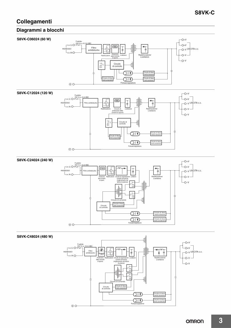
CollegamentiDiagrammi a blocchi
S8VK-C06024 (60 W)
Circuito di rileva-mento tensione
Fotoaccoppiatore
Raddrizzatore/Livellatore
c.a. (L)
INGRESSO
c.a. (N)
Circuitodi controllo
Fusibile:250 Vc.a. 6,3 A HBC
Circuito di rileva-mento sovratensioni
Filtroantidisturbo
Protezionedalla corrente
di spuntoRaddrizzatore Livellatore
Circuito di rileva-mento sovracorrente
+V
+V
−V
−V
−V
USCITA c.c.
S8VK-C12024 (120 W)
Fotoaccoppiatore
Filtro antidisturbo
c.a. (L)
INGRESSO
c.a. (N)
Fusibile: 250 Vc.a. 8 A HBC
Raddrizzatore Circuito di protezione dalle
correnti di spunto
Livellatore
Circuito di controllo
Raddrizzatore/Livellatore
Circuito di rileva-mento tensione
Circuito di rileva-mento sovratensioni
+V
+V
−V
−V
−V
USCITA c.c.
Circuito di rileva-mento sovracorrente
S8VK-C24024 (240 W)
Fotoaccoppiatore
Circuito di comando
Filtro antidisturbo
c.a. (L)
INGRESSO
c.a. (N)
Fusibile: 250 Vc.a. 8 A HBC
Raddrizzatore LivellatoreCircuito di soppressione correnti armoniche (miglioramento del fattore di potenza)
Circuito di rileva-mento tensione
Circuito di rileva-mento sovratensioni
+V
+V
−V
−V
−V
USCITA c.c.
Circuito di controllo
Circuito di rileva-mento sovracorrente
Protezione dalla corrente
di spunto
Raddrizzatore/Livellatore
S8VK-C48024 (480 W)
Fotoaccoppiatore
Circuito di comando
Filtroantidisturbo
c.a. (L)
INGRESSO
c.a. (N)
Fusibile: 250 Vc.a. 12 A HBC
Raddrizzatore LivellatoreCircuito di soppressione correnti armoniche
(miglioramento del fattore di potenza)
Circuito di controllo
Raddrizzatore/Livellatore
Circuito di rileva-mento tensione
Circuito di rileva-mento sovratensioni
+V
+V
−V
−V
−V
USCITA c.c.
Circuito di rileva-mento sovracorrente
Protezione dalla corrente
di spunto

S8VK-C
4
Descrizione del pannello frontale
*1. Il fusibile si trova sul lato sinistro(L). Non può essere sostituito dall’utente. Per un ingresso c.c., collegare la tensione positiva al terminale L.*2. Questo è il terminale di messa a terra negli standard di sicurezza. Mettere sempre a terra questo terminale.
Curve caratteristicheCurva di correzione della potenza60, 120, 240, 480 W
Nota: 1. A meno di 90 Vc.a., il valore di correzione è 2,5%/V2. Per un ingresso di alimentazione in c.c., ridurre il carico
indicato nella curva di correzione sopra riportata moltiplicando i seguenti coefficienti.S8VK-C06024/S8VK-C12024: 0.8S8VK-C24024/S8VK-C48024: 0.7
A. Montaggio standard40°C e oltre: il valore di correzione è 2,0%/°C
B. Montaggio fronte verso l’alto 30°C e oltre: il valore di correzione è 1,67%/°C
Modelli da 60 W Modelli da 120 W Modelli da 240 W Modelli da 480 WS8VK-C06024 S8VK-C12024 S8VK-C24024 S8VK-C48024
N. Tipo Funzione1 Terminali di ingresso (L), (N) Collegare le linee di ingresso a questi terminali*12 Terminale di messa a terra di protezione (PE) Collegare la terra a questo terminale*23 Terminali di uscita c.c. (−V), (+V) Collegare il carico a questi terminali.4 Spia di funzionamento (CC ON: verde) È accesa quando l’uscita in corrente continua (CC) è attiva.5 Regolatore della tensione di uscita (V.ADJ) Utilizzare questo dispositivo per regolare la tensione.
3
1 2
5
4
1 2
3
5
4
1 2
5
4
3
1 2 3
5
4
−40 −25 −10 0 10 20 30 40 50 60 70 80
120
100
80
60
40
20
0
Car
ico
(%)
Temperatura ambiente (°C)
A
B

S8VK-C
5
Montaggio
Protezione da sovraccaricoGrazie a questa funzione, il carico e l’alimentatore sono protetti automaticamente da sovracorrente.La protezione da sovraccarico si attiva quando la corrente in uscita supera un valore pari al 105% della corrente nominale.Quando la corrente in uscita rientra nell’intervallo dei valori nominali, la protezione da sovraccarico si disattiva automaticamente.
Nota: 1. I componenti interni possono deteriorarsi o danneggiarsi se durante il funzionamento perdura uno stato di sovracorrente o cortocircuito.
2. I componenti interni possono deteriorarsi o danneggiarsi se l’alimentatore viene utilizzato per applicazioni con frequenti correnti di spunto o sovraccarichi sul carico. Non utilizzare l’alimentatore per questo tipo di applicazioni.
Protezione da sovratensioniTenendo conto dell’eventualità di sovratensioni, è opportuno realizzare il sistema in modo tale che il carico non sia soggetto a una tensione eccessiva anche in caso di guasto del circuito di feedback dell’alimentatore. La tensione di uscita viene disattivata se diventa superiore a circa il 130% della tensione nominale. In questo caso è necessario togliere l’alimentazione di ingresso per almeno 3 min, quindi riattivarla.
Nota: non riattivare (ON) l’alimentazione fino a quando la causa della sovratensione non è stata rimossa.
Corrente di spunto, Tempo di avvio, Tempo di mantenimento dell’uscita
Nota: viene generato il doppio della corrente in ingresso o un valore superiore durante il funzionamento in parallelo o in caso di sistema ridondante.Pertanto, verificare le caratteristiche dei fusibili e di funzionamento degli interruttori accertandosi che i fusibili esterni non brucino e che gli interruttori automatici non vengano attivati dalla corrente di spunto.
(B) Montaggio con partefrontale verso l’alto
(A) Montaggio standard(verticale)
I valori riportati nei diagrammi precedenti sono solo di riferimento.
0 50 100
Corrente in uscita (%)
Tens
ione
di u
scita
(V
)
Funzionamentointermittente
+15%
−10%
0 V
+30%(circa)
Attivazione protezione da sovratensioni
Campo di regolazioneTensione
di uscita nominale
Tens
ione
di u
scita
(V
)
I valori visualizzati nel diagramma precedente sono solo di riferimento.
90% 96,5%
Tempo di avvio (1.000 ms max.)
Tensione di ingresso c.a.
Corrente di ingresso c.a.
Tensione di uscita
Corrente di spunto all’accensione
Ingresso OFFIngresso ON
Tempo di manteni-mento (20 ms min.)

S8VK-C
6
Applicazione dei modelli monofase su due fasiPer tutti i modelli monofase, S8VK-CIn generale l’alimentatore monofase OMRON può essere utilizzato su due fasi di un sistema trifase nelle seguenti condizioni.
1. La tensione di alimentazione è inferiore all’ingresso nominale massimo.L’alimentatore OMRON consente una tensione di ingresso minore o uguale a 240 Vc.a.+10% Se questa condizione viene soddisfatta, prima del collegamento verificare la tensione di ingresso tra due linee.
2. È richiesto un dispositivo di protezione esterno sulla linea di ingresso N per garantire la sicurezza. La linea N non dispone di alcuna protezione di fusibili internamente. È necessario collegare un fusibile o un interruttore automatico appropriato sulla linea di ingresso N come di seguito riportato.
Dati di riferimento
Affidabilità (MTBF)
ValoreModello monofase60 W: 630.000 h120 W: 490.000 h240 W: 270.000 h480 W: 190.000 h
Definizione
Il fattore MTBF (che significa tempo medio fra i guasti), viene calcolato facendo riferimento alla probabilità di guasti fortuiti degli apparecchi e indica l’affidabilità dei dispositivi.Tale valore non rappresenta quindi necessariamente la durata del prodotto.
Durata prevista 10 anni min.
Definizione
La durata indica un numero medio di ore di funzionamento a una temperatura ambiente di 40°C con un coefficiente di carico del 50%. Essa è generalmente determinata dalla durata del condensatore elettrolitico in alluminio incorporato.
Fusibile esterno o interruttore automatico
max. 240 Vc.a. +10%
Fusibile interno
Alimentatore
NL
L1 L2 L3 PE

S8VK-C
7
Dimensioni (unità: mm)
4,7(Scorrimento: 10 max.)
75,4 90 34,9
32
5
Fermo guida
Ø 3,6 (Bit n. 1)
Ø 3,6 (Bit n. 1)
3,5
(1) 110
106
7,62
S8VK-C06024 (60 W)
40
125
4,7(Scorrimento: 7,5 max.)
104,6
6,35 112,2
117,8
122,2
Fermo guida(10)
(4)(1)
34,7
Ø 5,0 (Bit n. 2)
Ø 5,0 (Bit n. 2)
6,35
S8VK-C12024 (120 W)
6,35
125
4,7(Scorrimento: 7,5 max.)60
104,6
Fermo guida
Ø 5,0 (Bit n. 2)
140
145,6
(10)
(4)(1)
150
34,7
Ø 5,0 (Bit n. 2)
6,35
S8VK-C24024 (240 W)
125
4,7(Scorrimento: 7,5 max.)
6,35 6,35
52,3
Fermo guida
95
140
145,6
(10)
(4)(1)
Ø 5,0 (Bit n. 2) Ø 5,0 (Bit n. 2)
150
34,7
S8VK-C48024 (480 W)

S8VK-C
8
Guida DIN (da ordinare separatamente)Nota: salvo diversa indicazione tutte le misure sono in millimetri.
(materiale: alluminio)PFP-100N PFP-50N
(materiale: alluminio)PFP-100N2
Piastrina di fermoPFP-M
Nota: se il modulo è esposto al rischio di urti o vibrazioni, utilizzare una guida DIN in acciaio. In caso contrario, l’abrasione dell’alluminio potrebbe produrre limatura di metallo.
4,5
15 25 2510 10
1.000 (500)*
25 25 15 (5)*
35 ±0,3
7,3 ±0,15
27 ±0,15
1
* I valori tra parentesi si riferiscono al modello PFP-50N.
4,5
15 25 2510 10
1.000
25 25 15 1 1,5
29,2242735 ±0,3
16
1,3
4,8
35,5 35,51,8
1,8
106,2
1
50
11,5
10Rondella elastica M4
Vite M4 × 8con testaa troncodi cono

S8VK-C
9
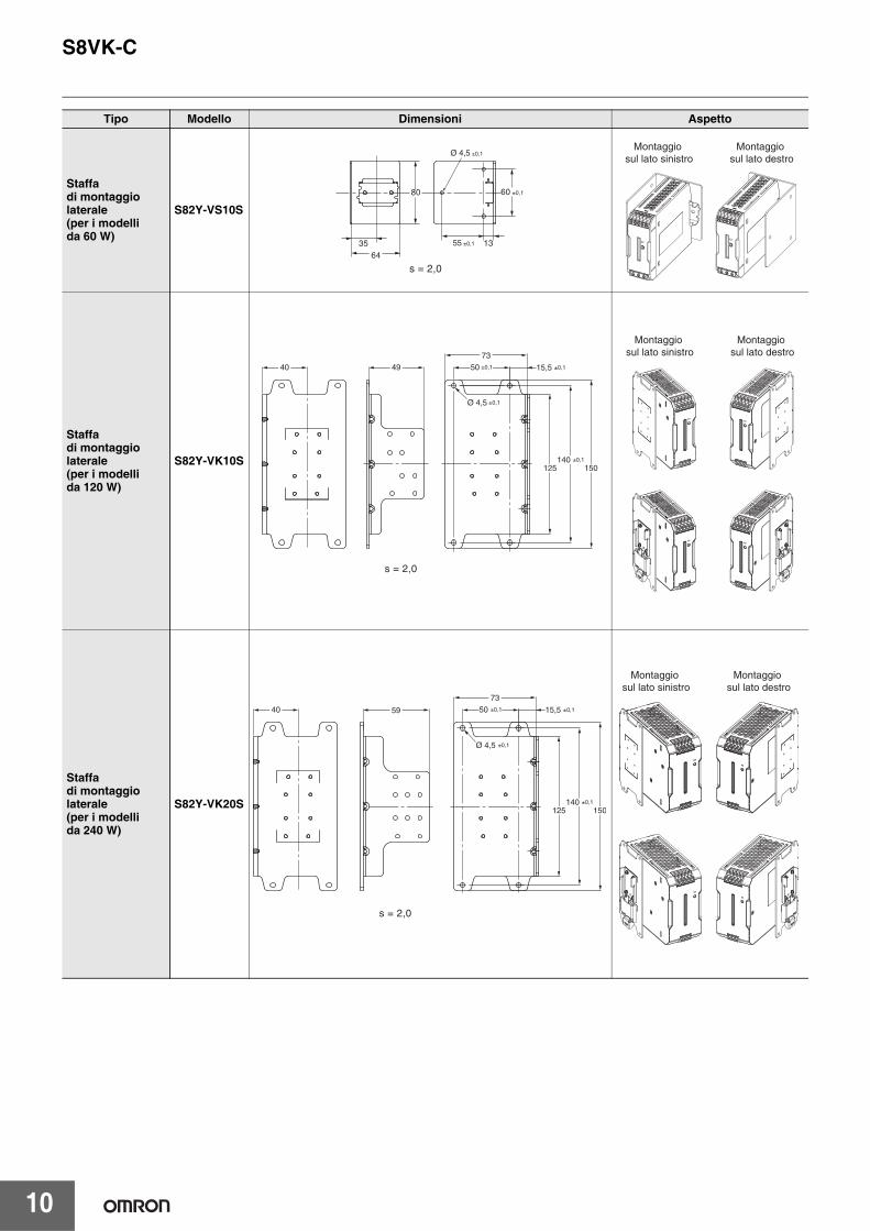
Staffe di montaggioTipo Modello
Staffa di montaggio frontale (per i modelli da 60 W) S82Y-VS10FStaffa di montaggio frontale (per i modelli da 120, 240 e 480 W) S82Y-VK10FStaffa di montaggio laterale (per i modelli da 60 W) S82Y-VS10SStaffa di montaggio laterale (per i modelli da 120 W) S82Y-VK10SStaffa di montaggio laterale (per i modelli da 240 W) S82Y-VK20S
Tipo Modello Dimensioni Aspetto
Staffa di montaggio frontale (per i modelli da 60 W)
S82Y-VS10F
Staffa di montaggio frontale (per i modelli da 120, 240 e 480 W)
S82Y-VK10F
41
35 ±0,1
4050
Ø 4,5 ±0,1
35 25
107,3
s = 1,0
25 ±0,1
140 ±0,1
150
38
Ø 4,5 ±0,1 5,4
s = 2,0
Modelli da 120 W Modelli da 240 W
S8VK-C
10
Tipo Modello Dimensioni Aspetto
Staffa di montaggio laterale(per i modelli da 60 W)
S82Y-VS10S
Staffa di montaggio laterale (per i modelli da 120 W)
S82Y-VK10S
Staffa di montaggio laterale (per i modelli da 240 W)
S82Y-VK20S
3564
s = 2,0
80 60 ±0,1
55 ±0,1 13
Ø 4,5 ±0,1Montaggio
sul lato sinistroMontaggio
sul lato destro
140 ±0,1
50 ±0,1 15,5 ±0,1
150125
73
Ø 4,5 ±0,1
4940
s = 2,0
Montaggio sul lato sinistro
Montaggio sul lato destro
140 ±0,1
50 ±0,1 15,5 ±0,1
150125
73
5940
Ø 4,5 ±0,1
s = 2,0
Montaggio sul lato sinistro
Montaggio sul lato destro

S8VK-C
11
Precauzioni per la sicurezzaAvvertenza
Significato dei simboli di sicurezza del prodotto
ATTENZIONEEsiste la possibilità che possano verificarsi scosse elettriche, incendi o guasti del prodotto. Non smontare, modificare o riparare il prodotto né toccarne le parti interne.
Pericolo di scottature. Non toccare il prodotto mentre è alimentato o subito dopo che è stato spento.
Pericolo di incendi. Stringere le viti dei terminali applicando una coppia di serraggio specifica (0,5… 0,6 N·m).
Pericolo di lesioni personali dovute a scosse elettriche. Non toccare i terminali quando il prodotto è alimentato. Chiudere sempre il coperchio dei terminali una volta effettuato il cablaggio.
Esiste la possibilità che possano verificarsi scosse elettriche, incendi o guasti del prodotto. Evitare che residui di metallo o di conduttori, pezzi di filo o altri detriti derivanti dai lavori d’installazione entrino inavvertitamente nel prodotto.
ATTENZIONE
Indica una situazione di potenziale pericolo che, se non evitata, può essere causa di lesioni non gravi a persone o danni alla proprietà.
Modalità d’uso per garantire la sicurezza
Commenti supplementari sulle operazioni da eseguire o da evitare per utilizzare il prodotto in modo sicuro.
Utilizzo corretto
Commenti supplementari sulle operazioni da eseguire o da evitare per garantire il corretto funzionamento del sistema e non comprometterne le prestazioni.
Utilizzato per indicare il rischio di scosse elettriche in specifiche condizioni.
Utilizzato per indicare il rischio di lesioni di lieve entità causate da temperature elevate.
Utilizzato come precauzione per azioni obbligatorie generali per le quali non è previsto simbolo specifico.
Utilizzato per indicare un divieto in presenza di rischi di lesioni non gravi, dovuti a scosse elettriche o altre cause, in caso di smontaggio del prodotto.

S8VK-C
12
Cablaggio• Collegare completamente il filo di messa a terra. Utilizzare un
terminale di messa a terra di protezione, come previsto dalle norme di sicurezza. Una messa a terra non adeguata può causare scosse elettriche o malfunzionamento del prodotto.
• Pericolo di incendio. Verificare che i terminali di ingresso e di uscita siano collegati correttamente.
• Non serrare la morsettiera applicando una forza superiore a 75 N.• Prima di accendere il prodotto, occorre rimuovere tutte le protezioni
applicate per la lavorazione sulla macchina per evitare che ostacolino la dissipazione del calore.
• Per il collegamento all’alimentatore S8VK-C utilizzare i cavi elencati di seguito in modo da evitare fumo o scintille dovuti a carichi anomali.
Terminali e cablaggio
• Rimuovere 8 mm di guaina dai cavi I/O quando si utilizzano morsettiere a molla.Nota: la corrente nominale dei terminali di uscita è di 10 A per terminale.
Verificare di utilizzare più terminali contemporaneamente per la corrente superiore al valore nominale del terminale. Quando viene applicata una corrente di 10 A o superiore, utilizzare almeno due terminali per il cavo positivo e il cavo negativo.
Ambiente di installazione• Non utilizzare l’alimentatore in luoghi soggetti a urti o vibrazioni.
Installare l’alimentatore il più lontano possibile da contattori o altri dispositivi che producono vibrazioni.
• Installare l’alimentatore lontano da sorgenti di disturbi intensi ad alta frequenza e colpi di corrente.
Durata• La durata di un alimentatore dipende da quella dei condensatori
elettrolitici all’interno. In questo caso è applicabile la legge di Arrhenius, in base alla quale la durata viene ridotta della metà per ogni aumento di 10°C e viene raddoppiata per ogni riduzione di 10°C. È quindi possibile aumentare la durata dell’alimentatore riducendone la temperatura interna.
Ambiente operativo e di stoccaggio • Conservare l’alimentatore a una temperatura compresa
tra −25 e 65°C e a un’umidità compresa tra 10 e 95%.• Non utilizzare l’alimentatore in aree esterne alla curva
di correzione per evitare il deterioramento o il danneggiamento dei componenti interni.
• Utilizzare l’alimentatore a un’umidità compresa tra 20% e 90%.• Non utilizzare l’alimentatore in luoghi esposti alla luce solare diretta.• Non utilizzare l’alimentatore in presenza di liquidi, corpi estranei
o gas corrosivi che potrebbero penetrare all’interno del prodotto.
Modalità d’uso per garantire la sicurezza
INGRESSO USCITA PE
ModelloDiametro dei fili elettrici americani
Cavo rigido/Cavo semirigido
Diametro dei fili elettrici americani
Cavo rigido/Cavo semirigido
Diametro dei fili elettrici americani
Cavo rigido/Cavo semirigido
S8VK-C06024 AWG22… 12 0,35… 4 mm2/0,35… 2,5 mm2 AWG20… 12 0,5… 4 mm2/
0,5… 2,5 mm2
AWG14 o spessore maggiore
2,5 mm2 o spessore maggiore/2,5 mm2 o spessore maggiore
S8VK-C12024 AWG22… 10 0,35… 6 mm2/0,35… 4 mm2 AWG18… 10 0,75… 6 mm2/
0,75… 4 mm2
S8VK-C24024 AWG20… 10 0,5… 6 mm2/0,5… 4 mm2 AWG14… 10 2,5… 6 mm2/
2,5… 4 mm2
S8VK-C48024 AWG16… 10 1,5… 6 mm2/1,5… 4 mm2 AWG12… 10 4… 6 mm2/
4 mm2

S8VK-C
13
Montaggio• Adottare misure appropriate per garantire un’adeguata
dissipazione del calore al fine di estendere l’affidabilità del prodotto. Durante la fase di montaggio, lasciare spazio sufficiente attorno ai dispositivi. Non utilizzare l’alimentatore in luoghi in cui la temperatura ambiente eccede i valori della curva di correzione.
• Nel praticare i fori di montaggio, accertarsi di non penetrare all’interno dei prodotti.
• Un montaggio errato impedisce un’adeguata dissipazione del calore, provocando l’eventuale deterioramento o danneggiamento dei componenti interni. Utilizzare il prodotto nell’ambito della curva di correzione adatta alla direzione di montaggio scelta.
• Utilizzare una staffa di montaggio per installare il prodotto orizzontalmente.
• La dissipazione del calore viene compromessa. Se il prodotto viene montato orizzontalmente, il lato con l’etichetta va sempre posizionato verso l’alto.
• Utilizzare l’alimentatore all’interno di un campo inferiore di 5°C ai valori della curva di correzione indicati nella sezione Curve caratteristiche a pagina 4 in caso di una spaziatura di installazione di 10 mm min. (20 mm max.) a sinistra e a destra.
Protezione da sovracorrente• I componenti interni possono deteriorarsi o danneggiarsi se
durante il funzionamento perdura uno stato di sovracorrente o cortocircuito.
• I componenti interni possono deteriorarsi o danneggiarsi se l’alimentatore viene utilizzato per applicazioni con frequenti correnti di spunto o sovraccarichi sul carico. Non utilizzare l’alimentatore per questo tipo di applicazioni.
• La spia c.c. ON (verde) lampeggia quando la funzione di protezione da sovraccarico è attiva.
Carica di una batteriaSe il carico è rappresentato da una batteria, prevedere un circuito di controllo della sovracorrente e un circuito di protezione da sovratensioni.
Regolatore della tensione di uscita (V.ADJ)• Il regolatore della tensione di uscita (V.ADJ) potrebbe
danneggiarsi se ruotato con forza eccessiva. Non esercitare una forza eccessiva.
• Dopo aver terminato la regolazione della tensione di uscita, verificare che il valore della potenza o della corrente in uscita non siano superiori a quelli nominali.
Montaggio su guida DINPer montare l’alimentatore su una guida DIN, appoggiare il lato superiore del sistema di aggancio (A) dell’alimentatore sulla guida e premere in direzione (B).
Per rimuovere il blocco base, spingere verso il basso la linguetta di bloccaggio (C) con un cacciavite a taglio ed estrarre l’alimentatore.
Funzionamento in serieÈ possibile collegare in serie due alimentatori.
Nota: 1. Il diodo è collegato come mostrato nella figura. In presenza di un cortocircuito sul carico, nell’alimentatore viene generata una tensione inversa che potrebbe deteriorare o danneggiare l’alimentatore. Collegare sempre il diodo come mostrato nella figura. Scegliere un diodo che abbia le seguenti caratteristiche:
2. Sebbene sia possibile collegare in serie anche prodotti con specifiche diverse, la corrente che attraversa il carico non deve mai superare la corrente nominale di uscita più piccola.
Impostazione uscita positiva/uscita negativa• Le uscite sono mobili (ad esempio, i circuiti primari e secondari
sono separati). Pertanto, è possibile impostare uscite positive e negative utilizzando due alimentatori.A tale fine, può essere utilizzato qualsiasi modello.Se vengono utilizzate uscite positive e negative, collegare alimentatori dello stesso modello come mostrato nella figura seguente. È possibile combinare capacità di uscita o tensioni di uscita differenti. Tuttavia, utilizzare per i carichi il valore minore tra le due correnti di uscita nominale massime.
Utilizzo corretto
*1. Convezione dell’aria*2. 20 mm min.
*1
*1*2
Tipo Diodo barriera Schottky
Rigidità dielettrica (VRRM) Un valore pari o superiore al doppio della tensione di uscita nominale
Corrente diretta (IF) Un valore pari o superiore al doppio della corrente di uscita nominale
(B)
(A)
(C)
30 mm min.
Fermo della guida
+V
−V
+V
−V
Giustoc.a. (L)
c.a. (N)
c.a. (L)
c.a. (N)
INGRESSO+V +V
0 V
−V
−V
INGRESSO+V
−V
Car
ico
Car
ico
S8VK-C
14
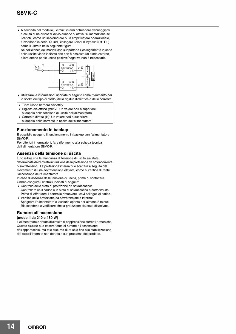
• A seconda del modello, i circuiti interni potrebbero danneggiarsi a causa di un errore di avvio quando si attiva l’alimentazione se i carichi, come un servomotore o un amplificatore operazionale, funzionano in serie. Quindi, collegare i diodi di bypass (D1, D2) come illustrato nella seguente figura.Se nell’elenco dei modelli che supportano il collegamento in serie delle uscite viene indicato che non è richiesto un diodo esterno, allora anche per le uscite positive/negative non è necessario.
• Utilizzare le informazioni riportate di seguito come riferimento per la scelta del tipo di diodo, della rigidità dielettrica e della corrente.
Funzionamento in backupÈ possibile eseguire il funzionamento in backup con l’alimentatore S8VK-R.Per ulteriori informazioni, fare riferimento alla scheda tecnica dell’alimentatore S8VK-R.
Assenza della tensione di uscitaÈ possibile che la mancanza di tensione di uscita sia stata determinata dall’entrata in funzione della protezione da sovracorrente o sovratensioni. La protezione interna può scattare a seguito del rilevamento di una sovratensione elevata, come si verifica durante l’accensione dell’alimentatore.In caso di assenza della tensione di uscita, prima di contattare Omron eseguire i controlli indicati di seguito:• Controllo dello stato di protezione da sovraccarico:
Controllare se il carico è in stato di sovraccarico o cortocircuito. Prima di effettuare il controllo rimuovere i cavi collegati al carico.
• Verifica della protezione da sovratensioni o interna: Spegnere l’alimentatore e lasciarlo spento per almeno 3 minuti. Riaccenderlo e verificare che la protezione sia stata disattivata.
Rumore all’accensione(modelli da 240 e 480 W)L’alimentatore è dotato di circuito di soppressione correnti armoniche. Questo circuito può essere fonte di rumore all’accensione dell’apparecchio, ma tale disturbo dura solo fino alla stabilizzazione dei circuiti interni e non denota alcun problema del prodotto.
• Tipo: Diodo barriera Schottky• Rigidità dielettrica (VRRM): Un valore pari o superiore
al doppio della tensione di uscita dell’alimentatore• Corrente diretta (IF): Un valore pari o superiore
al doppio della corrente in uscita dell’alimentatore
INGRESSO+V
D2
D1
−V
INGRESSO+V
−V
Car
ico
Car
ico
Car
ico

Garanzia e considerazioni sull’applicazioneLeggere attentamente le informazioni contenute nel presente documento
Prima di procedere all’acquisto del prodotto, leggere attentamente le informazioni contenute nel presente documento. Per eventuali domande o dubbi, rivolgersi al rappresentante OMRON di zona.
Garanzia e limitazioni di responsabilitàGARANZIAOMRON garantisce i propri prodotti da difetti di fabbricazione e di manodopera per un periodo di un anno (o per altro periodo specificato) dalla data di vendita da parte di OMRON.OMRON NON RICONOSCE ALTRA GARANZIA, ESPRESSA O IMPLICITA, COMPRESE, IN VIA ESEMPLIFICATIVA, LA GARANZIA DI COMMERCIABILITÀ, DI IDONEITÀ PER UN FINE PARTICOLARE E DI NON VIOLAZIONE DI DIRITTI ALTRUI. L’ACQUIRENTE O L’UTENTE RICONOSCE LA PROPRIA ESCLUSIVA RESPONSABILITÀ NELL’AVERE DETERMINATO L’IDONEITÀ DEL PRODOTTO A SODDISFARE I REQUISITI IMPLICITI NELL’USO PREVISTO DELLO STESSO. OMRON NON RICONOSCE ALTRA GARANZIA, ESPRESSA O IMPLICITA.
LIMITAZIONI DI RESPONSABILITÀOMRON NON SARÀ RESPONSABILE DEI DANNI, DELLE PERDITE DI PROFITTO O DELLE PERDITE COMMERCIALI SPECIALI, INDIRETTE O EMERGENTI RICONDUCIBILI AI PRODOTTI, ANCHE QUANDO LE RICHIESTE DI INDENNIZZO POGGINO SU CONTRATTO, GARANZIA, NEGLIGENZA O RESPONSABILITÀ INCONDIZIONATA.In nessun caso la responsabilità di OMRON potrà superare il prezzo del singolo prodotto in merito al quale è stata definita la responsabilità.IN NESSUN CASO OMRON SARÀ RESPONSABILE DELLA GARANZIA, DELLE RIPARAZIONI O DI ALTRA RICHIESTA DI INDENNIZZO RELATIVA AI PRODOTTI SE L’ANALISI CONDOTTA DA OMRON NON CONFERMERÀ CHE I PRODOTTI SONO STATI CORRETTAMENTE UTILIZZATI, IMMAGAZZINATI, INSTALLATI E SOTTOPOSTI A MANUTENZIONE, E CHE NON SONO STATI OGGETTO DI CONTAMINAZIONI, ABUSI, USI IMPROPRI, MODIFICHE O RIPARAZIONI INADEGUATE.
Considerazioni sull’applicazioneIDONEITÀ ALL’USO PREVISTOOMRON non sarà responsabile della conformità alle normative, ai codici e alle approvazioni per combinazioni di prodotti nell’applicazione del cliente o all’impiego dei prodotti.Adottare tutte le misure necessarie a determinare l’idoneità del prodotto ai sistemi, ai macchinari e alle apparecchiature con i quali verrà utilizzato.Essere a conoscenza e osservare tutte le proibizioni applicabili al prodotto.NON UTILIZZARE MAI I PRODOTTI IN APPLICAZIONI CHE IMPLICHINO GRAVI RISCHI PER L’INCOLUMITÀ DEL PERSONALE O DANNI ALLA PROPRIETÀ SENZA PRIMA AVERE APPURATO CHE L’INTERO SISTEMA SIA STATO PROGETTATO TENENDO IN CONSIDERAZIONE TALI RISCHI E CHE I PRODOTTI OMRON SIANO STATI CLASSIFICATI E INSTALLATI CORRETTAMENTE IN VISTA DELL’USO AL QUALE SONO DESTINATI NELL’AMBITO DELL’APPARECCHIATURA O DEL SISTEMA.
Dichiarazione di non responsabilitàDATI SULLE PRESTAZIONII dati sulle prestazioni forniti in questo documento non costituiscono una garanzia, bensì solo una guida alla scelta delle soluzioni più adeguate alle esigenze dell’utente. Essendo il risultato delle condizioni di collaudo di OMRON, tali dati devono essere messi in relazione agli effettivi requisiti di applicazione. Le prestazioni effettive sono soggette alle garanzie e limitazioni di responsabilità OMRON.
MODIFICHE ALLE SPECIFICHELe caratteristiche e gli accessori del prodotto sono soggetti a modifiche a scopo di perfezionamento o per altri motivi. Per confermare le caratteristiche effettive del prodotto acquistato, rivolgersi al rappresentante OMRON di zona.
PESI E MISUREPesi e misure sono nominali e non devono essere utilizzati per scopi di fabbricazione, anche quando sono indicati i valori di tolleranza.

In una prospettiva di miglioramento del prodotto, le informazioni contenute nel presente documento sono soggette a modifiche senza preavviso.Cat. No. T058-IT2-01
ITALIAOmron Electronics SpA Viale Certosa, 49 - 20149 MilanoTel: +39 02 32 681Fax: +39 02 32 68 282www.industrial.omron.it
Nord Ovest Tel: +39 02 326 88 00Milano Tel: +39 02 32 687 77Bologna Tel: +39 051 613 66 11Terni Tel: +39 074 45 45 11
SVIZZERAOmron Electronics AGSennweidstrasse 44, CH-6312 SteinhausenTel: +41 (0) 41 748 13 13Fax: +41 (0) 41 748 13 45www.industrial.omron.ch
Romanel Tel: +41 (0) 21 643 75 75

1
New Product
Switch Mode Power Supply
S8VK-T (120/240/480/960 W Models)
Worldwide 3-phase Power SupplyResistant in tough environmentsEasy and fast installationThe most compact class on the market
• Wide input range for worldwide applications: 380 to 480 VAC (320 to 576 VAC)
• Possible for 2-phase input usage*: 380 to 480 VAC (340 to 576 VAC)*When using the 960 W at 2-phase input, the power rating is 768 W.
• DC input can be available*:450 to 600 VDC (450 to 810 VDC)*Excluding 960 W
• High efficiency 91% typ. at 480 W model• Wide operation temperature range: –40 to 70C• Power Boost function at 120%• Meets LR maritime standards• EMS: Conforms to EN 61204-3
EMI: EN61204-3 Class B• RoHS Compliant
Model Number StructureModel Number Legend
Ordering InformationNote: For details on normal stock models, contact your nearest OMRON representative.
Power ratings Input voltage Output Voltage Output current Boost Current Model number
120 W 2-phase and 3-phase380 to 480 VAC450 to 600 VDC
24 V 5 A 6 A S8VK-T12024
240 W 24 V 10 A 12 A S8VK-T24024
480 W 24 V 20 A 24 A S8VK-T48024
960 W
3-phase380 to 480 VAC 24 V 40 A 48 A
S8VK-T960242-phase380 to 480 VAC 24 V 32 A -
! Refer to Safety Precautions for All Power Supplies and Safety Precautions on page 12.
1 2S8VK- T@@@@@
1. Power Ratings120: 120 W240: 240 W480: 480 W960: 960 W
2. Output voltage24: 24 V

S8VK-T
2
SpecificationsRatings, Characteristics, and Functions
Note: Refer to page 4 for notes 1 to 13.
Power rating 120 W 240 W
Item Output voltage 24 V 24 V
Efficiency 3-phase, 400 VAC input *11 89% typ. 89% typ.
Input
Voltage range *13-phase, 380 to 480 VAC (allowable range: 320 to 576 VAC) 2-phase, 380 to 480 VAC (allowable range: 340 to 576 VAC)450 to 600 VDC (allowable range: 450 to 810 VDC) *8
Frequency *1 50/60 Hz (47 to 63 Hz)
Current 3-phase, 400 VAC input *11 0.38 A typ. 0.69 A typ.
Power factor - -
Leakage current 3-phase, 400 VAC input 3.5 mA max./1.3 mA typ. 3.5 mA max./1.4 mA typ.
Inrush current (for a cold start at 25C) *2 3-phase, 400 VAC input 28 A typ. 29 A typ.
Output
Rated output current 5 A 10 A
Boost current 6 A 12 A
Voltage adjustment range *3 22.5 to 29.5 VDC (with V.ADJ) (guaranteed)
Ripple & Noise voltage *4 3-phase, 400 VAC input *11 160 mV p-p max. at 20 MHz of bandwidth 190 mV p-p max. at 20 MHz of bandwidth
Input variation influence *13 0.5% max.
Load variation influence *12 1.5% max.
Temperature variation influence 3-phase, 400 VAC input 0.05%/C max.
Start up time *2 3-phase, 400 VAC input *11 700 ms typ. 600 ms typ.
Hold time *2 3-phase, 400 VAC input *11 30 ms typ. 20 ms typ.
Additional functions
Overload protection Yes, automatic reset Yes, automatic reset
Overvoltage protection Yes, 130% or higher of rated output voltage, power shut off (shut off the input voltage and turn on the input again) *5
Series operation Yes (For up to two Power Supplies, external diodes are required.)
Parallel operation Yes (Refer to Engineering Data) (For up to two Power Supplies)
Output indicator Yes (LED: Green), lighting from 80% to 90% or more of rated voltage
InsulationWithstand voltage
3.0 kVAC for 1 min. (between all input terminals and output terminals) cutoff current 20 mA2.5 kVAC for 1 min. (between all input terminals and PE terminal) cutoff current 20 mA1.0 kVAC for 1 min. (between all output terminals and PE terminal) cutoff current 30 mA
Insulation resistance 100 M min. (between all output terminals and all input terminals / PE terminal) at 500 VDC
Environment
Ambient operating temperature –40 to 70C (However, only startup is guaranteed for between –40C to –25C. (3-phase only)) (Derating is required according to the temperature.) (with no condensation or icing)
Storage temperature –40 to 85C (with no condensation or icing)
Ambient operating humidity 0% to 95% (Storage humidity: 0% to 95%)
Vibration resistance 10 to 55 Hz, 0.375-mm half amplitude for 2 h each in X, Y, and Z directions
Shock resistance 150 m/s2, 3 times each in ±X, ±Y, and ±Z directions
ReliabilityMTBF 135,000 hrs min.
Life expectancy *10 10 years min.
Construction
Weight 700 g max. 1,000 g max.
Cooling fan No
Degree of protection IP20 by EN / IEC 60529
Standards
Harmonic current emissions Conforms to EN 61000-3-2
EMIConducted Emission Conforms to EN 61204-3 Class B EN 55011 Class B
Radiated Emission Conforms to EN 61204-3 Class B EN 55011 Class B
EMS Conforms to EN 61204-3 high severity levels
Approved Standards *6
UL Listed: UL 508 *7EN: EN 50178Lloyd’s standards *9ANSI/ISA 12.12.01 *7
UL Listed: UL 508 *7 UL UR: UL 60950-1 (Recognition)cUR: CSA C22.2 No.60950-1CSA: CSA C22.2 No.60950-1EN: EN 50178, EN 60950-1Lloyd’s standards *9ANSI/ISA 12.12.01 *7
Conformed StandardsSELV (EN 50178), PELV(EN 60204-1, EN 50178)Safety of Power Transformers (EN 61558-2-16)EN 50274 for Terminal parts
SELV (EN 60950-1/EN 50178/UL 60950-1)PELV (EN 60204-1, EN 50178)Safety of Power Transformers (EN 61558-2-16)EN 50274 for Terminal parts
SEMI Conforms to F47-0706 (3-phase, 380 to 480 VAC input)

S8VK-T
3
Note: Refer to page 4 for notes 1 to 18.
Power rating 480 W 960 W (768 W *18)
Item Output voltage 24 V 24 V
Efficiency 3-phase, 400 VAC input *11 91% typ. 92% typ.
Input
Voltage range *1
3-phase, 380 to 480 VAC (allowable range: 320 to 576 VAC) 2-phase, 380 to 480 VAC (allowable range: 340 to 576 VAC)450 to 600 VDC (allowable range: 450 to 810 VDC) *8
3-phase, 380 to 480 VAC (allowable range: 320 to 576 VAC) 2-phase, 380 to 480 VAC (allowable range: 340 to 576 VAC)
Frequency *1 50/60 Hz (47 to 63 Hz)
Current 3-phase, 400 VAC input *11 1.2 A typ. 2.1 A typ.
Power factor - -
Leakage current 3-phase, 400 VAC input 3.5 mA max./1.0 mA typ. 3.5 mA max./1.2 mA typ.
Inrush current (for a cold start at 25C) *2 3-phase, 400 VAC input 28 A typ.
Output
Rated output current 20 A 40 A at 3-phase (32 A at 2-phase)
Boost current 24 A 48 A at 3-phase (Not possible at 2-phase)
Voltage adjustment range *3 22.5 to 29.5 VDC (with V.ADJ) (guaranteed) 22.5 to 29.5 VDC (with V.ADJ) (guaranteed) *14
Ripple & Noise voltage *4 3-phase, 400 VAC input *11 130 mV p-p max. at 20 MHz of bandwidth 90 mV p-p max. at 20 MHz of bandwidth
Input variation influence *13 0.5% max.
Load variation influence *12 1.5% max.
Temperature variation influence 3-phase, 400 VAC input 0.05%/C max.
Start up time *2 3-phase, 400 VAC input *11 500 ms typ. 700 ms typ.
Hold time *2 3-phase, 400 VAC input *11 20 ms typ. 20 ms typ.
Additional functions
Overload protection Yes, automatic reset
Overvoltage protection Yes, 130% or higher of rated output voltage, power shut off (shut off the input voltage and turn on the input again) *5
Series operation Yes (For up to two Power Supplies, external diodes are required.)
Parallel operation Yes (Refer to Engineering Data) (For up to two Power Supplies)
Output indicator Yes (LED: Green), lighting from 80% to 90% or more of rated voltage
InsulationWithstand voltage
3.0 kVAC for 1 min. (between all input terminals and output terminals) cutoff current 20 mA2.5 kVAC for 1 min. (between all input terminals and PE terminal) cutoff current 20 mA1.0 kVAC for 1 min. (between all output terminals and PE terminal) cutoff current 30 mA
Insulation resistance 100 M min. (between all output terminals and all input terminals / PE terminal) at 500 VDC
Environment
Ambient operating temperature –40 to 70C (However, only startup is guaranteed for between –40C to –25C. (3-phase only)) (Derating is required according to the temperature.) (with no condensation or icing)
Storage temperature –40 to 85C (with no condensation or icing)
Ambient operating humidity 0% to 95% (Storage humidity: 0% to 95%)
Vibration resistance 10 to 55 Hz, 0.375-mm half amplitude for 2 h each in X, Y, and Z directions
Shock resistance 150 m/s2, 3 times each in ±X, ±Y, and ±Z directions
ReliabilityMTBF 135,000 hrs min.
Life expectancy *10 10 years min.
Construction
Weight 1,600 g max. 2,700 g max.
Cooling fan No
Degree of protection IP20 by EN / IEC 60529
Standards
Harmonic current emissions Conforms to EN 61000-3-2 *15
EMIConducted Emission Conforms to EN 61204-3 Class B EN 55011 Class B *16
Radiated Emission Conforms to EN 61204-3 Class B EN 55011 Class B *16
EMS Conforms to EN 61204-3 high severity levels
Approved Standards *6
UL Listed: UL 508 *7 UL UR: UL 60950-1 (Recognition)cUR: CSA C22.2 No.60950-1CSA: CSA C22.2 No.60950-1EN: EN 50178, EN 60950-1Lloyd’s standardsANSI/ISA 12.12.01 *7
Conformed Standards
SELV (EN 60950-1/EN 50178/UL 60950-1)PELV (EN 60204-1, EN 50178)Safety of Power Transformers (EN 61558-2-16)EN 50274 for Terminal parts
SEMI Conforms to F47-0706 (3-phase, 380 to 480 VAC input) *17

S8VK-T
4
*1. Do not use an inverter output for the Power Supply. Inverters with an output frequency of 50/60 Hz are available, but the rise in the internal temperature of the Power Supply may result in ignition or burning.
*2. For a cold start at 25C. Refer to Engineering Data on page 7 to 8 for details.*3. If the output voltage adjuster (V. ADJ) is turned, the voltage will increase by more than 29.5 VDC of the voltage adjustment range.
When adjusting the output voltage, confirm the actual output voltage from the Power Supply and be sure that the load is not damaged.*4. A characteristic when the ambient operating temperature is between –25 to 70C.*5. Refer to Overvoltage Protection on page 8 for the time when input voltage shuts off and input turns on again.*6. To meet safety standards, the S8VK-T must be protected with an external circuit-breaker or a fuse.
Be sure to use an external circuit-breaker or a fuse. Refer to Precautions for Safe Use on page 13 for details.*7. The following supplementary Fuse/Circuit Breaker must be installed in accordance with NEC.:
Model FAZ-D5/3-NA, FAZ-D5/3-RT or FAZ-D5/3-DU, EATON INDUSTRIES (AUSTRIA) GMBH (E235139), Model KLKD5, LITTELFUSE INC. (E10480)
*8. Safety Standards for a DC InputThe following standards apply to a 450 to 600 VDC input: UL 60950-1, EN 50178, EN 60950-1, and Lloyd's standards.
*9. In the case of using side-mounting bracket (S82Y-VK10S, S82YVK20S), Lloyd's Standards are not applicable.*10. The value is when rated output current is 50% or less, the ambient operating temperature is 40C or less, standard mounting, and rated input
voltage.*11. The value is when both rated output voltage and rated output current are satisfied.*12. 380 to 480 VAC input, in the range of 0 A to the rated output current.*13. This is the maximum variation in the output voltage when the input voltage is gradually changed within the allowable input voltage range at
the rated output voltage and rated output current.*14. Use at 26.4 VDC or lower for 2-phase input.*15. The S8VK-T Power Supply conforms to EN 61000-3-2 under the following conditions for 2-phase input.
480 W: rated output voltage, and 65% or less of rated output current960 W: rated output voltage, and 45% or less of rated output current
*16. The S8VK-T Power Supply conforms to EMI under the following conditions for 2-phase input.480 W: Conforms to class B: rated output voltage, and 65% or less of rated output current/
Conforms to class A: rated output voltage, and 65% to 100% of rated output current960 W: Conforms to class B: rated output voltage, and 45% or less of rated output current/
Conforms to class A: rated output voltage, and 45% to 100% of rated output current*17. 480 W: rated output voltage, and 50% or less of rated output current.
960 W: rated output voltage, and 92.5% or less of rated output current.*18. When using 2-phase input. Refer to 2-Phase Input Operation For 960 W Model in Precautions for Safe Use on page 16 for details.

S8VK-T
5
ConnectionsBlock Diagrams
Voltagedetection circuit
Photocoupler
Rectifier/smoothing
circuit
L1
L2INPUT
L3
Drive control circuit
+V
−V
DC OUTPUT
Overvoltagedetection circuit
Noise filter
lnrush current
protection
Smoothing circuit
Overcurrentdetection circuit
Rectifier
S8VK-T12024 (120 W)S8VK-T24024 (240 W)
S8VK-T48024 (480 W)S8VK-T96024 (960 W)
Voltagedetection circuit
Photocoupler
Rectifier/smoothing
circuit
L1
L2INPUT
L3
Drive control circuit
+V
−V
DC OUTPUT
Overvoltagedetection circuit
Noise filter
lnrush current
protection
Smoothing circuit
Overcurrentdetection circuit
Rectifier

S8VK-T
6
Construction and NomenclatureNomenclature
*1. For wiring, refer to Wiring in Precautions for Safe Use on page 13. *2. This is the protective earth terminal specified in the safety standards. Always ground this terminal. *3. For parallel operation, refer to Parallel Operation in Precautions for Safe Use on page 15.*4. For 2-phase input, refer to 2-Phase Input Operation For 960 W Model in Precautions for Safe Use on page 16.
120 W Model 240 W Model 480 W ModelS8VK-T12024 S8VK-T24024 S8VK-T48024
960 W ModelS8VK-T96024
No. Name Function1 Input terminals (L1), (L2), (L3) Connect the input lines to these terminals. *12 Protective Earth terminal (PE) / Ground Connect the ground line to this terminal. *23 DC Output terminals (V), (+V) Connect the load lines to these terminals.4 Output indicator (DC ON: Green) Lights while a direct current (DC) output is ON.5 Output voltage adjuster (V.ADJ) Use to adjust the voltage.6 Operation Switch *3 *4 To operate in parallel or 2-phase input, set the switch to the "B" side. (960 W model only).
1 2
3
5
4
3
5
4
1 2
5
4
1 2 3
1 2 3
5
4
6
Note:A: The output current can use 100% of the rated output current.B: Overcurrent protection limits the output current to 80% of the rated
output current.

S8VK-T
7
Engineering DataDerating Curve120 W (S8VK-T12024)
Note: This is the guaranteed value for startup. (3-phase only)
A. Standard mountingB. Face-up mounting at 480 VAC or lower or 678 VDC or lowerC. Face-up mounting at 576 VAC or lower or 810 VDC or lower
240 W (S8VK-T24024)
Note: This is the guaranteed value for startup. (3-phase only)
A. Standard mountingB. Face-up mounting at 480 VAC or lower or 678 VDC or lowerC. Face-up mounting at 576 VAC or lower or 810 VDC or lower
480 W (S8VK-T48024)
Note: This is the guaranteed value for startup. (3-phase only)
A. Standard mountingOver 528 VAC: the derating is 0.21%/VACOver 746 VAC: the derating is 0.16%/VDC
B. Face-up mounting at 480 VAC or lower or 678 VDC or lowerC. Face-up mounting at 576 VAC or lower or 810 VDC or lower
960 W (S8VK-T96024): Standard mounting
Note: This is the guaranteed value for startup. (3-phase only)
A. 3-Phase (340 VAC or over to 576 VAC or lower) For less than 340 VAC, it is possible to use with output voltage at 28.5 VDC or lower and load rate 60% or lower.
B. 2-Phase (380 VAC or over to 576 VAC or lower, and output voltage 26.4 VDC or lower)
C. 2-Phase (360 VAC or over to 380 VAC or lower, and output voltage 26.4 VDC or lower)For 340 VAC or over to less than 360 VAC, it is possible to use with output voltage at 26.4 VDC or lower, and whichever is the smaller of the load rate 60% or lower or the value of C.
960 W (S8VK-T96024): Face-up mounting
Note: This is the guaranteed value for startup. (3-phase only)
D. 3-Phase (340 VAC or over to 576 VAC or lower) For less than 340 VAC, it is possible to use with output voltage at 28.5 VDC or lower and load rate 60% or lower.
E. 2-Phase ( 380 VAC or over to 480 VAC or lower, and output voltage 26.4 VDC or lower)
F. 2-Phase (Over 480 VAC to 576 VAC or lower)For 340 VAC or over to less than 380 VAC, it is possible to use with output voltage at 26.4 VDC or lower, and whichever is the smaller of the load rate 60% or lower or the value of F.
−40 −25 −10 0 10 20 30 40 50 60 70 80
120
100
80
60
40
20
0
A
B
CLoad
rat
io (
%)
Ambient temperature (°C)
−40 −25 −10 0 10 20 30 40 50 60 70 80
120
100
80
60
40
20
0
A
B
CLoad
rat
io (
%)
Ambient temperature (°C)
−40 −25 −10 0 10 20 30 40 50 60 70 80
120
100
80
60
40
20
0
A
B
CLoad
rat
io (
%)
Ambient temperature (°C)
−40 −25 −10 0 10 20 30 40 50 60 70 80
120
100
80
60
40
20
0
B
C
A
Load
rat
io (
%)
Ambient temperature (°C)
−40 −25 −10 0 10 20 30 40 50 60 70 80
120
100
80
60
40
20
0
D
E
FLoad
rat
io (
%)
Ambient temperature (°C)

S8VK-T
8
Mounting
Overload ProtectionThe load and the power supply are automatically protected from overcurrent damage by this function.Overload protection is activated if the output current rises above 121% of the rated current.When the output current returns within the rated range, overload protection is automatically cleared.
Note: 1. Internal parts may occasionally deteriorate or be damaged if a short-circuited or overcurrent state continues during operation.
2. Internal parts may possibly deteriorate or be damaged if the Power Supply is used for applications with frequent inrush current or overloading at the load end. Do not use the Power Supply for such applications.
Overvoltage ProtectionConsider the possibility of an overvoltage and design the system so that the load will not be subjected to an excessive voltage even if the feedback circuit in the Power Supply fails. If an excessive voltage that is approximately 130% of the rated voltage or more is output, the output voltage is shut OFF. Reset the input power by turning it OFF for at least five minutes and then turning it back ON again.
Note: Do not turn ON the power again until the cause of the overvoltage has been removed.
Inrush Current, Startup Time, Output Hold Time
Note: Twice the input current or above will flow during the parallel operation or redundant system.Therefore, check the fusing characteristics of fuses and operating characteristics of breakers making sure that the external fuses will not burn out and the circuit breakers will not be activated by the inrush current.
Reference Value
(B) Face-up mounting(A) Standard (Vertical) mounting
The values shown in the above diagrams are for reference only.
0 50 100
Output current (%)
Out
put v
olta
ge (
V)
Intermittent operation
Reliability (MTBF)
Value
120 W: 390,000 h240 W: 350,000 h480 W: 280,000 h960 W: 260,000 h
Definition
MTBF stands for Mean Time Between Failures, which is calculated according to the probability of accidental device failures, and indicates reliability of devices.Therefore, it does not necessarily represent a life of the product.
Life expectancy 10 years. Min.
Definition
The life expectancy indicates average operating hours under the ambient temperature of 40C and a load rate of 50%. Normally this is determined by the life expectancy of the built-in aluminum electrolytic capacitor.
29.5 V
22.5 V
0 V
+30%(approx.)
Overvoltage protection operating
Variable rangeRated output voltage
Out
put v
olta
ge (
V)
The values shown in the above diagram is for reference only.
90% 96.5%
Startup time
AC input voltage
AC input current
Output voltage
Inrush current on input application
Input OFF Input ON
Hold time

S8VK-T
9
Dimensions (Unit: mm)
117.8
(4)
112.2
(1)
(10)
6.35
6.35
19.84.7(Sliding: 7.5 max.)Rail Stopper
40±1
104.6 125±1
122.2±1S8VK-T12024 (120 W)
104.6
(10)
6.35
4.7(Sliding: 7.5 max.)19.8Rail Stopper
6.35
60±1
125±1
145.6
(4)140
(1) 150±1S8VK-T24024 (240 W)
6.35 6.35
30 25
19.8(26.8)
Rail Stopper
4.7(Sliding: 7.5 max.)
(10)
125±1
145.6
(4)140
(1) 150±1
52.3
95±1
S8VK-T48024 (480 W)
10.1647.9 10.16
170
175.6
4.7(Sliding: 7.5 max.)
(10)
125±1
(4)
(1)
135±1
41.78 32.95
19.8
(36.7)Rail Stopper
180±1
S8VK-T96024 (960 W)

S8VK-T
10
DIN Rail (Order Separately)Note: All units are in millimeters unless otherwise indicated.
Mounting Rail (Material: Aluminum)PFP-100N PFP-50N
Mounting Rail (Material: Aluminum)PFP-100N2
End PlatePFP-M
Note: If there is a possibility that the Unit will be subject to vibration or shock, use a steel DIN Rail. Otherwise, metallic filings may result from aluminum abrasion.
4.5
15 25 2510 10
1,000 (500) *
25 25 15(5) *
35±0.3
7.3±0.15
27±0.15
1
* Values in parentheses are for the PFP-50N.
4.5
15 25 2510 10
1,000
25 25 15 1 1.5
29.2242735±0.3
16
1.3
4.8
35.5 35.51.8
1.8
106.2
1
50
11.5
10M4 spring washer
M4×8 pan-head screw

S8VK-T
11
Mounting Brackets
Note: Be sure to use the accessory screws.Mounting screw tightening torque (recommended): 4.43 to 5.31 lb-in (0.5 to 0.6 N·m)
* You can mount the side of the Power Supply to a DIN Rail by removing the DIN Rail Back-mounting Bracket and then attaching a Side-mounting Bracket to the Power Supply.
Name Model Qty used
Front-mounting bracket (for 120, 240 and 480 W models) S82Y-VK10F 1
Front-mounting bracket (for 960 W model) S82Y-VK10F 2
Side-mounting bracket (for 120 W model) S82Y-VK10S 1
Side-mounting bracket (for 240 W model) S82Y-VK20S 1
Type Model Dimensions Appearance
Front-mounting bracket (for 120, 240, 480 W and 960 W models)
S82Y-VK10F
Side-mounting bracket (For 120 W model)
S82Y-VK10S
Side-mounting bracket (For 240 W model)
S82Y-VK20S
38
150140±0.1
25±0.1
4-4.5 dia.±0.1
5.464±0.1
t = 2.0
For 960W type
120 W model
960 W model
240 W model
140±0.1
50±0.1 15.5±0.1
150125
73
4-4.5 dia.±0.1
4940
t = 2.0
Left-side mounting Right-side mounting
Left-side mounting(DIN Rail) *
Right-side mounting(DIN Rail) *
140±0.1
50±0.1 15.5±0.1
150125
73
5940
4-4.5 dia.±0.1
t = 2.0
Left-side mounting Right-side mounting
Left-side mounting(DIN Rail) *
Right-side mounting(DIN Rail) *

S8VK-T
12
Safety PrecautionsWarning Indications
Meaning of Product Safety Symbols
!CAUTIONMinor electric shock, fire, or Product failure may occasionally occur. Do not disassemble, modify, or repair the Product or touch the interior of the Product.
Minor burns may occasionally occur. Do not touch the Product while power is being supplied or immediately after power is turned OFF.
Fire may occasionally occur. Tighten terminal screws to the specified torque.S8VK-T12024, S8VK-T24024, S8VK-T48024: 4.43 to 5.31 lb-in (0.5 to 0.6 N•m)S8VK-T96024: 10.62 to 13.28 lb-in (1.2 to 1.5 N•m)
Minor injury due to electric shock may occasionally occur. Do not touch the terminals while power is being supplied.
Minor electric shock, fire, or Product failure may occasionally occur. Do not allow any pieces of metal or conductors or any clippings or cuttings resulting from installation work to enter the Product.
If the external breaker or fuse is tripped, the equipment may have been seriously damaged.Do not turn ON the input again.
CAUTION
Indicates a potentially hazardous situation which, if not avoided, may result in minor or moderate injury or in property damage.
Precautions for Safe Use
Supplementary comments on what to do or avoid doing, to use the product safely.
Precautions for Correct Use
Supplementary comments on what to do or avoid doing, to prevent failure to operate, malfunction or undesirable effect on product performance.
Used to warn of the risk of electric shock under specific conditions.
Used to warn of the risk of minor injury caused by high temperatures.
Used for general mandatory action precautions for which there is no specified symbol.
Used to indicate prohibition when there is a risk of minor injury from electrical shock or other source if the product is disassembled.

S8VK-T
13
Wiring Connect the ground completely. A protective earthing terminal
stipulated in safety standards is used. Electric shock or malfunction may occur if the ground is not connected completely.
Minor fire may possibly occur. Ensure that input and output terminals are wired correctly.
Do not apply more than 75-N force to the terminal block when tightening it.
Be sure to remove the sheet covering the Product for machining before power-ON so that it does not interfere with heat dissipation.
To comply with safety standards and to ensure equipment safety, connect the input to the S8VK-T through one of the following Breakers or Fuses.
Power circuit-breakers
Note: Do not use the S8VK-T96024 with a DC input.
Use the following material for the wires to be connected to the S8VK-T to prevent smoking or ignition caused by abnormal loads or phase failure.
Wire the input as shown in the following figures depends on your power distribution system. Do not connect the neutral line in a 3-phase, 4-wire system.
Recommended Wire Type/Cross-sectional Area and Stripping Length
The wire insertion hole, and applicable screwdriver of the terminal block are as follows.
Installation Environment Do not use the Power Supply in locations subject to shocks or
vibrations. In particular, install the Power Supply as far away as possible from contactors or other devices that are a vibration source. For usage onboard a ship, always attach an End Plate (PFP-M) to both sides of the Power Supply to hold the Power Supply in place.
Install the Power Supply well away from any sources of strong, high-frequency noise and surge.
Operating Life The life of a Power Supply is determined by the life of the
electrolytic capacitors used inside. Here, Arrhenius Law applies, i.e., the life will be cut in half for each rise of 10C or the life will be
doubled for each drop of 10C. The life of the Power Supply can thus be increased by reducing its internal temperature.
Ambient Operating and Storage Environments Store the Power Supply at a temperature of 40 to 85C and a
humidity of 0% to 95%. Do not use the Power Supply in areas outside the derating curve
otherwise, internal parts may occasionally deteriorate or be damaged.
Use the Power Supply at a humidity of 0% to 95%. Do not use the Power Supply in locations subject to direct sunlight. Do not use the Power Supply in locations where liquids, foreign
matter, or corrosive gases may enter the interior of Products.
Precautions for Safe Use
Model Input Power circuit-breakers
S8VK-T12024S8VK-T24024
3-phaseCircuit breaker Conforming UL/CE480 V, 5 A, characteristic D, 3-pole, or equivalent breaker
2-phase/DC Fuse Conforming UL/CE 600 V, 5 A Fast Acting or identical function fuse
S8VK-T48024S8VK-T96024
3-phaseCircuit breaker Conforming UL/CE 480 V, 5 A, characteristic D, 3-pole, or equivalent breaker
2-phase/DC Fuse Conforming UL/CE 600 V, 10 A Fast Acting or identical function fuse
L1
TN-S
L2L3NPE
L1
TN-C
L2L3
PEN
L1FUSE
2-phase
L2(L3)PE
L1
TT
L2L3N
L1
IT
L2L3
+
DC
-PE
FUSE
ModelINPUT OUTPUT PE / Ground
Wire tripping LengthAmerican
Wire GaugeSolid Wire/Stranded Wire
AmericanWire Gauge
Solid Wire/Stranded Wire
AmericanWire Gauge
Solid Wire/Stranded Wire
S8VK-T12024 AWG22 to 10 0.35 to 6 mm2
/0.35 to 4 mm2 AWG18 to 10 0.75 to 6 mm2
/0.75 to 4 mm2
AWG14 to 10 2.5 to 6 mm2 /2.5 to 4 mm2 8 to 10 mmS8VK-T24024 AWG22 to 10 0.35 to 6 mm2
/0.35 to 4 mm2 AWG14 to 10 2.5 to 6 mm2
/2.5 to 4 mm2
S8VK-T48024 AWG20 to 10 0.5 to 6 mm2
/0.5 to 4 mm2 AWG12 to 10 4 to 6 mm2
/4 mm2
S8VK-T96024 AWG16 to 6 1.5 to 16 mm2
/1.5 to 16 mm2 AWG8 to 6 10 to 16 mm2
/10 to 16 mm2 AWG14 to 6 2.5 to 16 mm2 /2.5 to 16 mm2 13 to 16 mm
Model
Wire Insertion Hole (Refer to the diagram on the right) Applicable Screwdriver
W L No. Driver Diameter Length
S8VK-T120242.9 2.9 #2 4.9 mm max. 10 mm min.S8VK-T24024
S8VK-T48024S8VK-T96024 5.4 5 #2 5.1 mm max. 12 mm min. W
L

S8VK-T
14
Mounting Take adequate measures to ensure proper heat dissipation to
increase the long-term reliability of the Product. Be sure to allow convection in the atmosphere around devices when mounting. Do not use in locations where the ambient temperature exceeds the range of the derating curve.
When cutting out holes for mounting, make sure that cuttings do not enter the interior of the Products.
Improper mounting will interfere with heat dissipation and may occasionally result in deterioration or damage of internal parts. Use the Product within the derating curve for the mounting direction that is used.
Overload Protection Internal parts may possibly deteriorate or be damaged if a
short-circuited or overcurrent state continues during operation. Internal parts may possibly deteriorate or be damaged if the Power
Supply is used for applications with frequent inrush current or overloading at the load end. Do not use the Power Supply for such applications.
The DC ON indicator (green) flashes if the overload protection function operates.
Charging a BatteryIf you connect a battery as the load, install overcurrent control and overvoltage protection circuits.
Output Voltage Adjuster (V.ADJ) The output voltage adjuster (V.ADJ) may possibly be damaged if it
is turned with unnecessary force. Do not turn the adjuster with excessive force.
After completing output voltage adjustment, be sure that the output capacity or output current does not exceed the rated output capacity or rated output current.
DIN Rail MountingTo mount the Block on a DIN Rail, hook portion (A) of the Block onto the rail and press the Block in direction (B).
To dismount the Block, pull down portion (C) with a flat-blade screwdriver and pull out the Block.
Power Boost FunctionFor All ModelsPower Boost is a function that can output the temporary repeated boost current larger than the rated current. However, it should meet the following four Boost current conditions.1. Time that the boost current flows: t12. The maximum value of the boost current: lp3. The average output current: lave4. The time ratio of the boost current flow: Duty
Note: Boost current conditions
Do not allow the boost current to continue for more than 10 seconds.Also, do not let the duty cycle exceed the boost current conditions.These conditions may damage the Power supply.
Ensure that the average current of one cycle of the boost current does not exceed the rated output current.This may damage the Power Supply.
Lessen the load of the boost load current by adjusting the ambient temperature and the mounting direction.
Power Boost Function is not possible for the S8VK-T 960 W at 2-phase input or in parallel operation.
Series OperationTwo power supplies can be connected in series.
Note: 1. The diode is connected as shown in the figure. If the load is short-circuited, a reverse voltage will be generated inside the Power Supply. If this occurs the Power Supply may possibly deteriorate or be damaged. Always connect a diode as shown in the figure. Select a diode having the following ratings.
2. Although Products having different specifications can be connected in series, the current flowing through the load must not exceed the smaller rated output current.
*1. Convection of air*2. 20 mm min.*1
*1
*2
(B)
(A)
(C)
30 mm min.
Rail stopper
Type Schottky Barrier diode
Dielectric strength (VRRM) Twice the rated output voltage or above
Forward current (IF) Twice the rated output current or above
• t1 • Ip • lave
≤ 10 s≤ Rated boost current≤ Rated current
Duty= t1 + t2
t1 × 100 [%] ≤ 30%
[A]
Ip: Boost current
Rated current
lave: Average current
t2 t1 ou
tput
cur
rent
+V
−V
+V
−V
L1
L2
L3
L2
L1
L3
Load

S8VK-T
15
Making Positive/Negative Outputs The outputs are floating outputs (i.e., the primary circuits and
secondary circuits are separated). You can therefore make positive and negative outputs by using two Power Supplies.You can make positive and negative outputs with any of the models.If positive and negative outputs are used, connect Power Supplies of the same model as in the following figure. (Combinations with different output capacities or output voltages can be made. However, use the lower of the two maximum rated output currents as the current to the loads.)
Depending on the model, internal circuits may be damaged due to startup failure when the power is turned ON if loads such as a servomotor or operational amplifier may operate in series. Therefore, connect bypass diodes (D1, D2) as shown in the following figure.If the list of models that support series connection of outputs says that an external diode is not required, an external diode is also not required for positive/negative outputs.
Use the following information as a guide to the diode type, dielectric strength, and current.
Parallel OperationParallel operation is used when the output current from one Power Supply is insufficient for the load. Power Supplies are connected in parallel to increase the output current.Two Power Supplies can be connected in parallel.1. Parallel operation is possible only if the standard mounting and
3-phase input is used.Maintain an ambient temperature of between -25 and 40°C.
2. For parallel operation, always use two Power Supplies with the same capacity.
3. Use the output voltage adjusters (V. ADJ) to adjust the difference in the output voltages between the two Power Supplies to 50 mV or less.
4. If the output current from the two Power Supplies is not balanced, the Power Supply with the higher output voltage will operate in an overcurrent protection state, which will extremely reduce its service life. After you adjust the difference in the output voltages between the two Power Supplies, make sure that the currents are well balanced.
5. The length and thickness of each wire connected to the load and each unit must be the same so that there is no difference in the voltage drop value between the load and the output terminals of each Power Supply.
6. For Parallel Operation with units 120 W, 240 W S8VK-T Power Supplies, connect diodes or S8VK-R to the outputs of each unit if sudden load variation influence occurs in the ambient operation environment.Refer to the S8VK-R datasheet (Catalog No.: T059) for S8VK-R specifications and the model number for each capacity.
7. The internal parts may occasionally be deteriorated or broken. Be sure to set the OPERATION SWITCH to B when using S8VK-T 480 W, 960 W for Parallel Operation.For Parallel Operation with units 960 W S8VK-T Power Supplies, connect diodes to the outputs of each unit if sudden load variation influence occurs in the ambient operation environment.
Use the following information as a guide to the diode type, dielectric strength, and current.
Type Schottky Barrier diode
Dielectric strength (VRRM) Twice the rated output voltage or above
Forward current (IF) Twice the rated output current or above
+V
−V
+V
−V
+V
0 V
−V
L1
L2
L3
L2
L1
L3
Load
Load
+V
−V
+V
−V
L1
L2
L3
L2
L1
L3
Load
Load
Load
D2
D1
Type Schottky Barrier diode
Dielectric strength (VRRM) Twice the rated output voltage or above
Forward current (IF) Twice the rated output current or above
+V
−V
+V
−V
+V
−V
L1
L2
L3
L2
L1
L3
Load
S8VK-R
IN 1
IN 2
S8VK-T
S8VK-T
+V
−V
+V
−V
L1
L2
L3
L2
L1
L3
Load

S8VK-T
16
Backup OperationBackup operation is possible if you use two Power Supplies of the same model.Even if one Power Supplies fails, operation can be continued with the other Power Supply.Make sure that the maximum load does not exceed the capacity of one Power Supply.For backup operation, connect the S8VK-R for 120 W, 240 W, and 480 W.Refer to the S8VK-R datasheet (Catalog No.: T059) for S8VK-R specifications and the model number for each capacity.
For 960 W, always connect diodes to the output sides of the two Power Supplies as shown in the following diagram.
Use the following information as a guide to the diode type, dielectric strength, and current.
Increase the output voltage setting of Power Supply A and Power Supply B by the drop in the forward voltage (VF) of diodes D1 and D2.Also, the diodes will cause a power loss equivalent to the Power Supply output current (IOUT) times the diode forward voltage (VF). Therefore, cooling measures must be implemented so that the temperature of the diodes decreases to the catalog value or lower.
Because of the load power and power loss due to the diodes, do not exceed the rated power of one Power Supply (rated output voltage × rated output current).
In Case There Is No Output VoltageThe possible cause for no output voltage may be that the overcurrent or overvoltage protection has operated. The internal protection may operate if a large amount of surge voltage such as a lightening surge occurs while turning ON the power supply.In case there is no output voltage, please check the following points before contacting us: Checking overload protected status:
Check whether the load is in overload status or is short-circuited. Remove wires to load when checking.
Checking overvoltage or internal protection: Turn the power supply OFF once, and leave it OFF for at least 5 minutes. Then turn it ON again to see if this clears the condition.
2-Phase Input Operation For 960 W ModelThe internal parts may occasionally be deteriorated or broken. Be sure to set the OPERATION SWITCH to B when using S8VK-T 960 W at 2-phase input.
Type Schottky Barrier diode
Dielectric strength (VRRM) Twice the rated output voltage or above
Forward current (IF) Twice the rated output current or above
+V
−V
+V
−V
+V
−V
L1
L2
L3
L2
L1
L3
Load
S8VK-R
IN 1
IN 2
S8VK-T
S8VK-T
+V
−V
+V
−V
L1
L2
L3
L2
L1
L3
A
B
D1
D2
Load
Note:A: The output current can use 100%
of the rated output current.B: Overcurrent protection limits the
output current to 80% of the rated output current.

S8VK-T
17
Recommended Replacement Periods and Periodic Replacement for Preventive MaintenanceThe recommended replacement period for preventive maintenance is greatly influenced by the application environment of the product. As a guideline, the recommended replacement period is 7 to 10 years.*To prevent failures or accidents that can be caused by using a product beyond its service live, we recommend that you replace the product as early as possible within the recommended replacement period.However, bear in mind that the recommended replacement period is for reference only and does not guarantee the life of the product.
Many electronic components are used in the product and the product depends on the correct operation of these components to achieve the original product functions and performance.However, the influence of the ambient temperature on aluminum electrolytic capacitors is large, and the service life is reduced by half for each 10C rise in temperature (Arrhenius law).When the capacity reduction life of the electrolytic capacitor is reached, the product failures or accidents may occur.We therefore recommend that you replace the product periodically to minimize product failures or accidents in advance.* The recommended replacement period applies under the following conditions: rated input voltage, load rate of 50% max., ambient temperature
of 40C max., and the standard mounting method. (The fan is excluded for models with fans.)
This product model is designed with a service life of 10 years minimum under the above conditions.
Terms and Conditions AgreementRead and understand this catalog.
Please read and understand this catalog before purchasing the products. Please consult your OMRON representative if you have any questions or comments.
Warranties.(a) Exclusive Warranty. Omron’s exclusive warranty is that the Products will be free from defects in materials and workmanship
for a period of twelve months from the date of sale by Omron (or such other period expressed in writing by Omron). Omron disclaims all other warranties, express or implied.
(b) Limitations. OMRON MAKES NO WARRANTY OR REPRESENTATION, EXPRESS OR IMPLIED, ABOUT NON-INFRINGEMENT, MERCHANTABILITY OR FITNESS FOR A PARTICULAR PURPOSE OF THE PRODUCTS. BUYER ACKNOWLEDGES THAT IT ALONE HAS DETERMINED THAT THE PRODUCTS WILL SUITABLY MEET THE REQUIREMENTS OF THEIR INTENDED USE.
Omron further disclaims all warranties and responsibility of any type for claims or expenses based on infringement by the Products or otherwise of any intellectual property right. (c) Buyer Remedy. Omron’s sole obligation hereunder shall be, at Omron’s election, to (i) replace (in the form originally shipped with Buyer responsible for labor charges for removal or replacement thereof) the non-complying Product, (ii) repair the non-complying Product, or (iii) repay or credit Buyer an amount equal to the purchase price of the non-complying Product; provided that in no event shall Omron be responsible for warranty, repair, indemnity or any other claims or expenses regarding the Products unless Omron’s analysis confirms that the Products were properly handled, stored, installed and maintained and not subject to contamination, abuse, misuse or inappropriate modification. Return of any Products by Buyer must be approved in writing by Omron before shipment. Omron Companies shall not be liable for the suitability or unsuitability or the results from the use of Products in combination with any electrical or electronic components, circuits, system assemblies or any other materials or substances or environments. Any advice, recommendations or information given orally or in writing, are not to be construed as an amendment or addition to the above warranty.
See http://www.omron.com/global/ or contact your Omron representative for published information.
Limitation on Liability; Etc.OMRON COMPANIES SHALL NOT BE LIABLE FOR SPECIAL, INDIRECT, INCIDENTAL, OR CONSEQUENTIAL DAMAGES, LOSS OF PROFITS OR PRODUCTION OR COMMERCIAL LOSS IN ANY WAY CONNECTED WITH THE PRODUCTS, WHETHER SUCH CLAIM IS BASED IN CONTRACT, WARRANTY, NEGLIGENCE OR STRICT LIABILITY.
Further, in no event shall liability of Omron Companies exceed the individual price of the Product on which liability is asserted.
Suitability of Use.Omron Companies shall not be responsible for conformity with any standards, codes or regulations which apply to the combination of the Product in the Buyer’s application or use of the Product. At Buyer’s request, Omron will provide applicable third party certification documents identifying ratings and limitations of use which apply to the Product. This information by itself is not sufficient for a complete determination of the suitability of the Product in combination with the end product, machine, system, or other application or use. Buyer shall be solely responsible for determining appropriateness of the particular Product with respect to Buyer’s application, product or system. Buyer shall take application responsibility in all cases.
NEVER USE THE PRODUCT FOR AN APPLICATION INVOLVING SERIOUS RISK TO LIFE OR PROPERTY OR IN LARGE QUANTITIES WITHOUT ENSURING THAT THE SYSTEM AS A WHOLE HAS BEEN DESIGNED TO ADDRESS THE RISKS, AND THAT THE OMRON PRODUCT(S) IS PROPERLY RATED AND INSTALLED FOR THE INTENDED USE WITHIN THE OVERALL EQUIPMENT OR SYSTEM.
Programmable Products.Omron Companies shall not be responsible for the user’s programming of a programmable Product, or any consequence thereof.
Performance Data.Data presented in Omron Company websites, catalogs and other materials is provided as a guide for the user in determining suitability and does not constitute a warranty. It may represent the result of Omron’s test conditions, and the user must correlate it to actual application requirements. Actual performance is subject to the Omron’s Warranty and Limitations of Liability.
Change in Specifications.Product specifications and accessories may be changed at any time based on improvements and other reasons. It is our practice to change part numbers when published ratings or features are changed, or when significant construction changes are made. However, some specifications of the Product may be changed without any notice. When in doubt, special part numbers may be assigned to fix or establish key specifications for your application. Please consult with your Omron’s representative at any time to confirm actual specifications of purchased Product.
Errors and Omissions.Information presented by Omron Companies has been checked and is believed to be accurate; however, no responsibility is assumed for clerical, typographical or proofreading errors or omissions.

Authorized Distributor:
In the interest of product improvement, specifications are subject to change without notice.
Cat. No. T061-E1-02-X 0616 (0414)
© OMRON Corporation 2014-2016 All Rights Reserved.
OMRON Corporation Industrial Automation Company
OMRON ELECTRONICS LLC2895 Greenspoint Parkway, Suite 200 Hoffman Estates, IL 60169 U.S.A.Tel: (1) 847-843-7900/Fax: (1) 847-843-7787
Regional HeadquartersOMRON EUROPE B.V.Wegalaan 67-69, 2132 JD HoofddorpThe NetherlandsTel: (31)2356-81-300/Fax: (31)2356-81-388
Contact: www.ia.omron.comKyoto, JAPAN
OMRON ASIA PACIFIC PTE. LTD.No. 438A Alexandra Road # 05-05/08 (Lobby 2), Alexandra Technopark, Singapore 119967Tel: (65) 6835-3011/Fax: (65) 6835-2711
OMRON (CHINA) CO., LTD.Room 2211, Bank of China Tower, 200 Yin Cheng Zhong Road, PuDong New Area, Shanghai, 200120, ChinaTel: (86) 21-5037-2222/Fax: (86) 21-5037-2200