Aerotermi Unit Heaters - Preventivo Certificazione … ed alette in alluminio. La geometria 25-22...
12
Aerotermi Unit Heaters
Transcript of Aerotermi Unit Heaters - Preventivo Certificazione … ed alette in alluminio. La geometria 25-22...
Aerotermi
Unit Heaters
2
ComponentiTechnical specification
Cassa portante Struttura in lamiera di acciaio spessore 1 mm, verniciata a forno conpolveri epossipoliestere ad alto spessore coprente, colore RAL 7035.Gli angoli sono rifiniti con particolari in ABS della stessa colorazionedelle alette.
Deflettori ariaIn metallo verniciato, RAL 7031, di colorazione scura per evitare un’al-terazione del colore con il depositarsi della polvere (vista la loro dislo-cazione). Sono montati orizzontalmente sulla parte anteriore dell’appa-
recchio con un sistema a molla che consente la rotazione di ogni sin-golo deflettore nella direzione desiderata e l’eventuale rimozione peroperazioni di pulizia della batteria di scambio termico.
Motore elettricoPuò essere a 4 o 6 poli con alimentazione 230-400V; 4/8 poli a dop-pia velocità selezionabile manualmente, monotensione (400V). I moto-ri sono tutti trifase 50 Hz ed hanno grado di protezione IP55.
VentilatoreAssiale con pale a falce in alluminio per permettere maggiori presta-
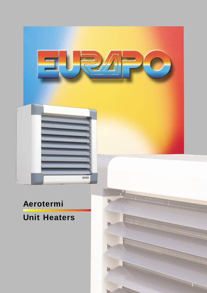
Gli aerotermi EURAPO sono caratterizzati da un design moderno ecurato nei minimi particolari, con linee sobrie e morbide che li rendo-no particolarmente indicati anche in applicazioni dove l’impatto esteti-co riveste una certa importanza (centri commerciali, palestre, centri fie-ristici, ecc.) oltre che in altri edifici ad uso industriale e civile di mediee grandi dimensioni (capannoni, chiese, ecc.).Un’accurata ed attenta progettazione ha permesso di coniugare gli ele-vati standard qualitativi, che ormai da anni contraddistinguono tutta laproduzione EURAPO (qualità dei materiali, affidabilità nel tempo…),con ottimi rendimenti termici sia in caldo che in freddo, e bassi livellisonori, garantendo in questo modo un miglior comfort ambientale.Abitualmente utilizzati in funzione di riscaldamento, su specifica richie-sta la nuova serie di aerotermi EURAPO è adesso disponibile ancheper il funzionamento in condizionamento.Le caratteristiche principali degli aerotermi EURAPO possono esserecosì riassunte:
Funzionamento in riscaldamento e condizionamento.Flusso d’aria orizzontale.Orientamento orizzontale dell’aria: ruotando l’unità rispetto al suo asse verticale.Orientamento verticale dell’aria: agendo a piacimento sui deflettori (ciascuno di essi è indipendente dagli altri).Modelli disponibili in 5 grandezze (100/500) con 2 diversi tipi di batteria (2 o 3 ranghi) e 3 diverse tipologie di motore (4, 6 e 4/8 poli), per ottenere fino a 30 diverse configurazioni.Semplicità d’installazione.
EURAPO unit heaters have a new design with particular care ondetails. The smooth shapes and nice aesthetics suggest an installationon Commercial Centres, Gyms, Exhibition Centres and so on, in addi-tion to other sites (industrial and big civilian buildings).EURAPO combines the high quality level, which is a well-known cha-racteristic of all EURAPO products, to excellent performances and lowsound pressure levels.In addition to the standard operation in heating mode, it is possible toorder the ATH unit heaters for cooling applications.
Main features:Cooling and heating operation.Horizontal air-flow direction.Possibility to adjust the horizontal air-flow direction by rotating the unit on its own vertical shaft.Possibility to adjust the vertical air-flow direction by acting on the independent blades.5 sizes available (100÷500) with 2- or 3-row coils and 4, 6 or 4/8 poles motors, in order to obtain 30 different configurations.Easy installation.
GeneralitàGeneral informations
3
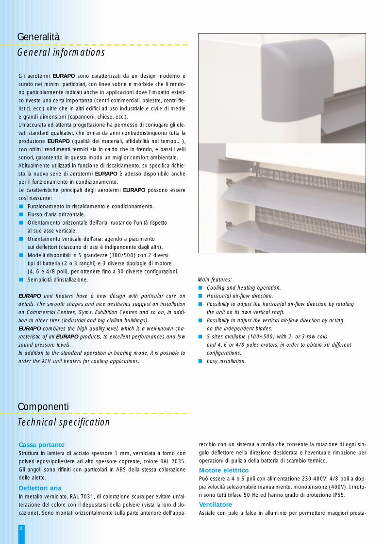
zioni con una minor rumorosità. Esso è protetto da una griglia antin-fortunistica verniciata a polveri epossipoliestere applicata con supportiantivibranti in neoprene per ridurre possibili vibrazioni.
Batteria di scambioLa batteria di scambio, a 2 o 3 ranghi, è del tipo tradizionale: tubi inrame ed alette in alluminio. La geometria 25-22 con tubi Ø 3/8” per-mette di avere una superficie di scambio molto omogenea, mentre l’a-deguato numero di circuiti di alimentazione garantisce delle portate edelle perdite di carico lato acqua ottimali.
AttacchiSono da 1” G femmina, posti sull’asse dell’aerotermo e precisamenteingresso acqua in basso ed uscita in alto, e sono dotati di sistema antitorsione.
ImballoOgni modello viene consegnato in una robusta scatola di cartone all’e-sterno della quale viene riportata una targhetta che identifica il model-lo contenuto.
CasingThe frame is made of 1 mm thick galvanized steel, painted with ovendried epoxy-polyester powders, RAL 7035. The corners are made ofABS material having the same colour of the blades.
BladesThe deflecting blades are made of galvanized steel painted in a darkcolour (RAL 7031), to prevent the deformation of the colour due todust and heat. They are mounted horizontally on the front part of theunit with a spring system, which allows the rotation of every singleblade in the proper direction and also the removal of the same, inorder to clean the coil.
Electric motorThe motors can have 4, 6 or 4/8 poles. All motors are 3-phase 50 Hzwith IP55 protection.
Fan motorAxial fan with crescent-shaped blades, in order to obtain higher perfor-mances with the lowest sound level. It is protected by an accident-pre-vention grill, painted with oven dried epoxy-polyester powders. Anti-vibrating neoprene couplings reduce possible vibrations.
Heat exchangerTraditional 2- or 3-row coils with copper tubes and aluminium fins. Theparticular geometry 25-22 with Ø 3/8” tubes grants an uniformexchanging area and the proper combination of supply circuits give anoptimal water flow and water pressure drop.
Water connections1” G female with antitorsion structure, located on the unit heater’s axis.The water intake is on the bottom of the unit, water outlet on the top.
PackingEach model is packed on a carton box with a label which identifies the unit.
AccessoriAccessories
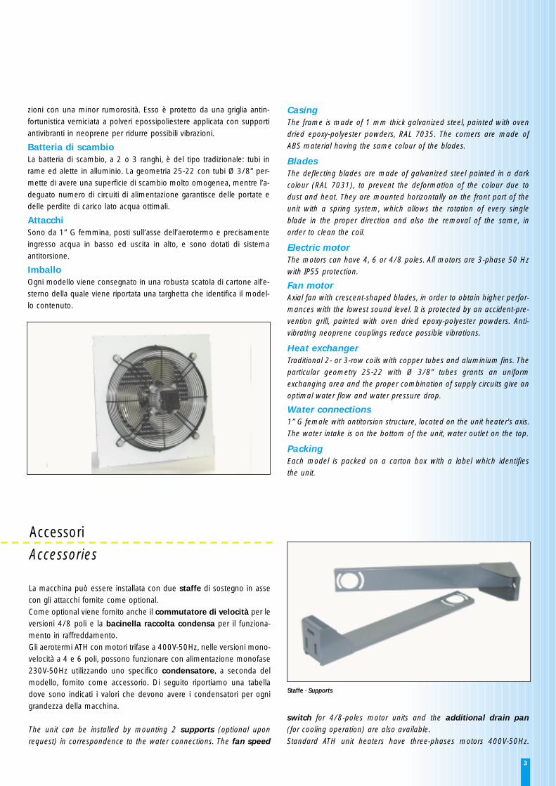
La macchina può essere installata con due staffe di sostegno in assecon gli attacchi fornite come optional. Come optional viene fornito anche il commutatore di velocità per leversioni 4/8 poli e la bacinella raccolta condensa per il funziona-mento in raffreddamento.Gli aerotermi ATH con motori trifase a 400V-50Hz, nelle versioni mono-velocità a 4 e 6 poli, possono funzionare con alimentazione monofase230V-50Hz utilizzando uno specifico condensatore, a seconda delmodello, fornito come accessorio. Di seguito riportiamo una tabelladove sono indicati i valori che devono avere i condensatori per ognigrandezza della macchina.
The unit can be installed by mounting 2 supports (optional uponrequest) in correspondence to the water connections. The fan speed
switch for 4/8-poles motor units and the additional drain pan(for cooling operation) are also available.Standard ATH unit heaters have three-phases motors 400V-50Hz.
Staffe · Supports
4
Dispersioni termiche edificioLe dispersioni termiche dell’edificio possono essere determinate utiliz-zando i metodi usuali e tenendo in debito conto le stratificazioni ditemperatura che sono inevitabili in ambienti di grande altezza. La stra-tificazione aumenta inoltre con l’aumentare della temperatura di uscitadell’aria dall’apparecchio.Questo fenomeno provoca un maggiore flusso di calore attraverso isoffitti nella misura riportata dalla tabella seguente in funzione dell’al-tezza dell’edificio:
Building heat lossThe building heat loss can be calculated by well considering the tem-perature’s stratification in rooms of considerable height. The stratifica-tion increases by increasing the outlet air temperature of the unit.This fact causes a certain amount of heat loss through the ceiling, asindicated below:
Altezza edificio (m) Dispersione termicaHigh of the building (m) Heat loss
4 15%
5 20%
6 25%
7 30%
8 35%
9 40%
10 50%
Numero degli apparecchi e portata d’aria Il numero di aerotermi da installare deve essere scelto in funzione delladisposizione dell’edificio e delle dispersioni termiche dello stesso.La portata d’aria complessiva (in m3/h) fatta circolare dagli aerotermideve essere almeno pari a 2-2,5 volte il volume da riscaldare espres-so in m3.
Number of units and air volumeThe quantity of unit heaters to be installed must take into consideration
their position and the heat loss of the building.The total air volume (m3/h) must be equal or higher than 2-2.5 timesthe volume to be heated (m3).
Temperatura d’uscita dell’ariaÈ consigliato non far funzionare l’aerotermo con temperature uscita ariatroppo elevate onde evitare stratificazioni dell’aria. A tale scopo si con-siglia che la batteria riscaldante sia a 2 ranghi.
Outlet air temperatureIt is advisable not to make the unit work with too high outlet air tem-perature, to avoid the stratification of the air. Therefore we suggest touse 2-row heating coils.
RumorositàLa rumorosità degli aerotermi è in funzione soprattutto della velocitàperiferica delle pale del ventilatore e quindi aumenta con il numero deigiri e con il diametro della ventola. Per consentire una scelta oculatadelle apparecchiature anche dal punto di vista della rumorosità, letabelle dei dati tecnici riportano anche i valori di pressione sonoramisurati in dB(A) alla distanza di 5 metri dell’apparecchio (funzionantealla velocità massima) in posizione frontale ed ambiente libero.
Noise levelsThe noise level of the Unit heaters depends on the peripheral speed ofthe fans. It is directly proportional to the revolutions and the diameterof the impeller. The technical tables show the sound pressure levels indB(A) at the maximum speed, at 5 m distance, facing the unit in anopen-field ambient.
Tipo di flusso ariaGli aerotermi ATH a flusso orizzontale (per montaggio a parete) sonoadatti principalmente per ambienti di altezza non superiore a 6-7 metri. Nelle versioni 4/8 poli, devono essere scelti in modo tale da raggiun-gere la resa richiesta alla bassa velocità (8 poli).
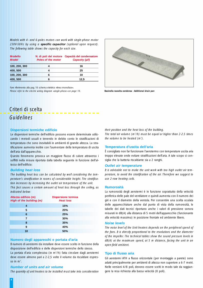
Models with 4- and 6-poles motors can work with single-phase motor230V-50Hz by using a specific capacitor (optional upon request).The following table shows the capacity for each size.
Modello N. di poli del motore Capacità del condensatoreModel Poles of the motor Capacity (µF)
100, 200, 300 4 16
400, 500 4 25
100, 200, 300 6 10
400, 500 6 12,5
Fare riferimento alla pag. 10 schema elettrico «linea monofase».Please refer to the electric wiring diagram «single-phase» on page 10.
Criteri di sceltaGuidelines
Bacinella raccolta condensa · Additional drain pan
5
Type of air flowATH Unit Heaters are designed to be mounted on the wall. They havehorizontal air flow and are suitable for ambient with height of maxi-mum 6-7 meters.In 4/8 poles version the Unit Heaters must be chosen by selecting therequested capacity at the minimum speed (8 poles).
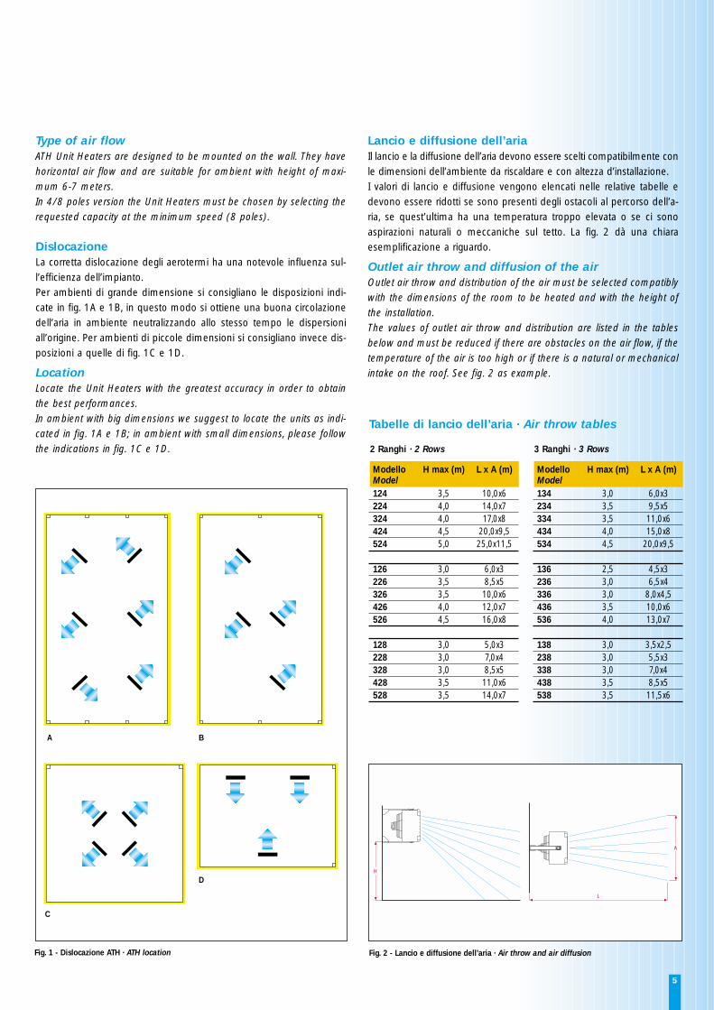
DislocazioneLa corretta dislocazione degli aerotermi ha una notevole influenza sul-l’efficienza dell’impianto.Per ambienti di grande dimensione si consigliano le disposizioni indi-cate in fig. 1A e 1B, in questo modo si ottiene una buona circolazionedell’aria in ambiente neutralizzando allo stesso tempo le dispersioniall’origine. Per ambienti di piccole dimensioni si consigliano invece dis-posizioni a quelle di fig. 1C e 1D.
LocationLocate the Unit Heaters with the greatest accuracy in order to obtainthe best performances.In ambient with big dimensions we suggest to locate the units as indi-cated in fig. 1A e 1B; in ambient with small dimensions, please followthe indications in fig. 1C e 1D.
Lancio e diffusione dell’ariaIl lancio e la diffusione dell’aria devono essere scelti compatibilmente conle dimensioni dell’ambiente da riscaldare e con altezza d’installazione.I valori di lancio e diffusione vengono elencati nelle relative tabelle edevono essere ridotti se sono presenti degli ostacoli al percorso dell’a-ria, se quest’ultima ha una temperatura troppo elevata o se ci sonoaspirazioni naturali o meccaniche sul tetto. La fig. 2 dà una chiaraesemplificazione a riguardo.
Outlet air throw and diffusion of the airOutlet air throw and distribution of the air must be selected compatiblywith the dimensions of the room to be heated and with the height ofthe installation.The values of outlet air throw and distribution are listed in the tablesbelow and must be reduced if there are obstacles on the air flow, if thetemperature of the air is too high or if there is a natural or mechanicalintake on the roof. See fig. 2 as example.
H
A
L
A B
C
D
2 Ranghi · 2 Rows
Modello H max (m) L x A (m)Model124 3,5 10,0x6224 4,0 14,0x7324 4,0 17,0x8424 4,5 20,0x9,5524 5,0 25,0x11,5
126 3,0 6,0x3226 3,5 8,5x5326 3,5 10,0x6426 4,0 12,0x7526 4,5 16,0x8
128 3,0 5,0x3228 3,0 7,0x4328 3,0 8,5x5428 3,5 11,0x6528 3,5 14,0x7
3 Ranghi · 3 Rows
Modello H max (m) L x A (m)Model134 3,0 6,0x3234 3,5 9,5x5334 3,5 11,0x6434 4,0 15,0x8534 4,5 20,0x9,5
136 2,5 4,5x3236 3,0 6,5x4336 3,0 8,0x4,5436 3,5 10,0x6536 4,0 13,0x7
138 3,0 3,5x2,5238 3,0 5,5x3338 3,0 7,0x4438 3,5 8,5x5538 3,5 11,5x6
Tabelle di lancio dell’aria · Air throw tables
Fig. 2 - Lancio e diffusione dell’aria · Air throw and air diffusionFig. 1 - Dislocazione ATH · ATH location
6
PrestazioniPerformances
Raffr
edda
men
toCo
olin
g (2
)Al
tri d
ati
Furt
her
data
Risc
alda
men
toH
eatin
g (1
)
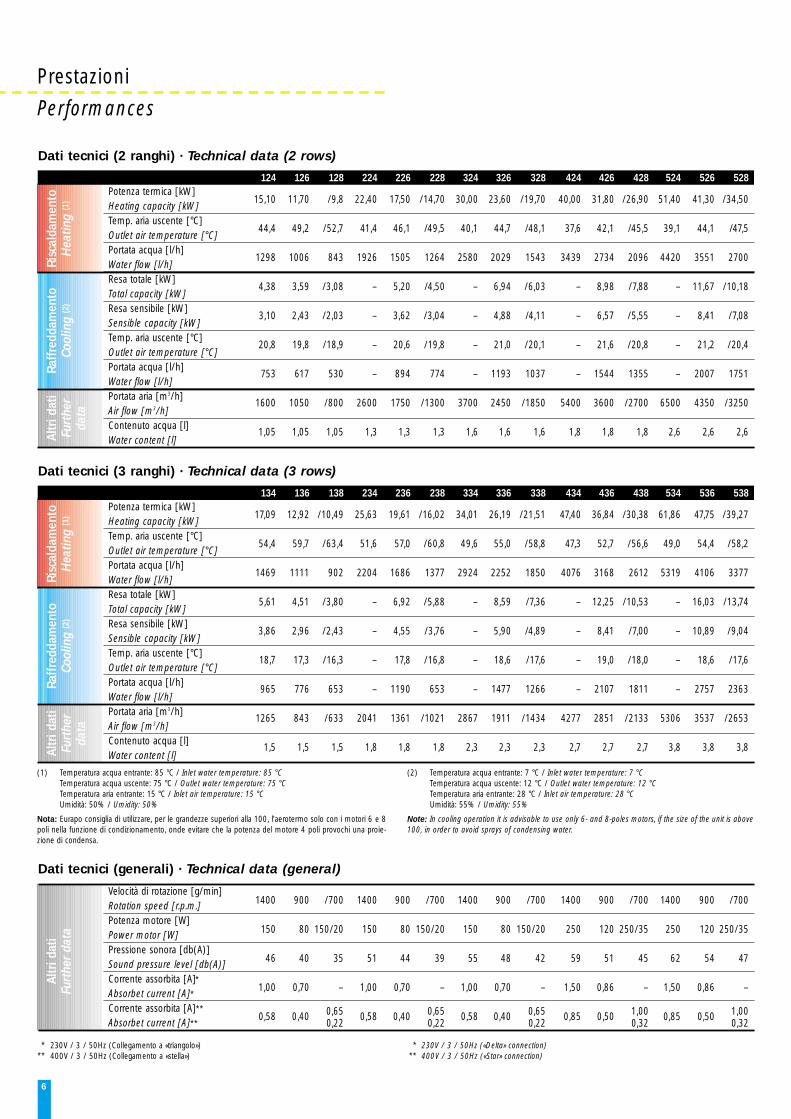
Dati tecnici (2 ranghi) · Technical data (2 rows)
* 230V / 3 / 50Hz (Collegamento a «triangolo»)** 400V / 3 / 50Hz (Collegamento a «stella»)
* 230V / 3 / 50Hz («Delta» connection)** 400V / 3 / 50Hz («Star» connection)
(1) Temperatura acqua entrante: 85 °C / Inlet water temperature: 85 °CTemperatura acqua uscente: 75 °C / Outlet water temperature: 75 °CTemperatura aria entrante: 15 °C / Inlet air temperature: 15 °CUmidità: 50% / Umidity: 50%
Nota: Eurapo consiglia di utilizzare, per le grandezze superiori alla 100, l’aerotermo solo con i motori 6 e 8poli nella funzione di condizionamento, onde evitare che la potenza del motore 4 poli provochi una proie-zione di condensa.
(2) Temperatura acqua entrante: 7 °C / Inlet water temperature: 7 °CTemperatura acqua uscente: 12 °C / Outlet water temperature: 12 °CTemperatura aria entrante: 28 °C / Inlet air temperature: 28 °CUmidità: 55% / Umidity: 55%
Note: In cooling operation it is advisable to use only 6- and 8-poles motors, if the size of the unit is above100, in order to avoid sprays of condensing water.
Potenza termica [kW]Heating capacity [ kW]Temp. aria uscente [ °C]Outlet air temperature [ °C]Portata acqua [ l/h]Water flow [ l/h]Resa totale [kW]Total capacity [ kW]Resa sensibile [ kW]Sensible capacity [ kW]Temp. aria uscente [ °C]Outlet air temperature [ °C]Portata acqua [ l/h]Water flow [ l/h]Portata aria [m3/h]Air flow [m3/h]Contenuto acqua [ l]Water content [ l]
124 126 128 224 226 228 324 326 328 424 426 428 524 526 528
15,10 11,70 /9,8 22,40 17,50 /14,70 30,00 23,60 /19,70 40,00 31,80 /26,90 51,40 41,30 /34,50
44,4 49,2 /52,7 41,4 46,1 /49,5 40,1 44,7 /48,1 37,6 42,1 /45,5 39,1 44,1 /47,5
1298 1006 843 1926 1505 1264 2580 2029 1543 3439 2734 2096 4420 3551 2700
4,38 3,59 /3,08 – 5,20 /4,50 – 6,94 /6,03 – 8,98 /7,88 – 11,67 /10,18
3,10 2,43 /2,03 – 3,62 /3,04 – 4,88 /4,11 – 6,57 /5,55 – 8,41 /7,08
20,8 19,8 /18,9 – 20,6 /19,8 – 21,0 /20,1 – 21,6 /20,8 – 21,2 /20,4
753 617 530 – 894 774 – 1193 1037 – 1544 1355 – 2007 1751
1600 1050 /800 2600 1750 /1300 3700 2450 /1850 5400 3600 /2700 6500 4350 /3250
1,05 1,05 1,05 1,3 1,3 1,3 1,6 1,6 1,6 1,8 1,8 1,8 2,6 2,6 2,6
Raffr
edda
men
toCo
olin
g (2
)Al
tri d
ati
Furt
her
data
Risc
alda
men
toH
eatin
g (1
)
Dati tecnici (3 ranghi) · Technical data (3 rows)
Potenza termica [kW]Heating capacity [ kW]Temp. aria uscente [ °C]Outlet air temperature [ °C]Portata acqua [ l/h]Water flow [ l/h]Resa totale [kW]Total capacity [ kW]Resa sensibile [ kW]Sensible capacity [ kW]Temp. aria uscente [ °C]Outlet air temperature [ °C]Portata acqua [ l/h]Water flow [ l/h]Portata aria [m3/h]Air flow [m3/h]Contenuto acqua [ l]Water content [ l]
134 136 138 234 236 238 334 336 338 434 436 438 534 536 538
17,09 12,92 /10,49 25,63 19,61 /16,02 34,01 26,19 /21,51 47,40 36,84 /30,38 61,86 47,75 /39,27
54,4 59,7 /63,4 51,6 57,0 /60,8 49,6 55,0 /58,8 47,3 52,7 /56,6 49,0 54,4 /58,2
1469 1111 902 2204 1686 1377 2924 2252 1850 4076 3168 2612 5319 4106 3377
5,61 4,51 /3,80 – 6,92 /5,88 – 8,59 /7,36 – 12,25 /10,53 – 16,03 /13,74
3,86 2,96 /2,43 – 4,55 /3,76 – 5,90 /4,89 – 8,41 /7,00 – 10,89 /9,04
18,7 17,3 /16,3 – 17,8 /16,8 – 18,6 /17,6 – 19,0 /18,0 – 18,6 /17,6
965 776 653 – 1190 653 – 1477 1266 – 2107 1811 – 2757 2363
1265 843 /633 2041 1361 /1021 2867 1911 /1434 4277 2851 /2133 5306 3537 /2653
1,5 1,5 1,5 1,8 1,8 1,8 2,3 2,3 2,3 2,7 2,7 2,7 3,8 3,8 3,8
Altr
i dat
iFu
rthe
r dat
a
Dati tecnici (generali) · Technical data (general)
Velocità di rotazione [g/min]Rotation speed [ r.p.m.]Potenza motore [W]Power motor [W]Pressione sonora [db(A)]Sound pressure level [db(A)]Corrente assorbita [A]*Absorbet current [A]*Corrente assorbita [A]**
Absorbet current [A]**
1400 900 /700 1400 900 /700 1400 900 /700 1400 900 /700 1400 900 /700
150 80 150/20 150 80 150/20 150 80 150/20 250 120 250/35 250 120 250/35
46 40 35 51 44 39 55 48 42 59 51 45 62 54 47
1,00 0,70 – 1,00 0,70 – 1,00 0,70 – 1,50 0,86 – 1,50 0,86 –
0,58 0,40 0,65 0,58 0,40 0,65 0,58 0,40 0,65 0,85 0,50 1,00 0,85 0,50 1,000,22 0,22 0,22 0,32 0,32

7
DimensioniDimensions
A
B
300
C
ATTACCHI FEMMINA G1"
CONNECTIONS G1" FEMALE
A B
142
100 200 300 400 500A 366 420 474 528 636B 536 590 644 698 806C 480 465 465 470 470kg 22,0 25,2 27,0 31,0 38,4
100 200 300 400 500A 366 420 474 528 636B 536 590 644 698 806C 480 465 465 470 470kg 23,1 26,3 28,6 33,0 41,8
Tem
pera
tura
aria
ent
rant
eIn
let a
ir te
mpe
ratu
re
Coefficienti di correzione · Corrections factors
5 °C 0,85 1,00 1,08 1,15 1,23 1,38
10 °C 0,77 0,92 1,00 1,08 1,15 1,31
15 °C 0,69 0,85 0,92 1,00 1,08 1,23
20 °C 0,62 0,77 0,85 0,92 1,00 1,15
25 °C 0,54 0,69 0,77 0,85 0,92 1,08
30 °C 0,46 0,62 0,69 0,77 0,85 1,00
0,68 0,79 0,89 1,00 1,10 1,21
0,63 0,74 0,84 0,95 1,05 1,16
0,58 0,68 0,79 0,89 1,00 1,10
0,53 0,63 0,74 0,84 0,95 1,05
0,47 0,58 0,68 0,79 0,89 1,00
0,42 0,53 0,63 0,74 0,84 0,95
65 °C 75 °C 80 °C 85 °C 90 °C 100 °C 80 °C 90 °C 100 °C 110 °C 120 °C 130 °C
Temperatura acqua entrante · ∆t 10 °CInlet water temperature · ∆t 10 °C
Temperatura acqua entrante · ∆t 20 °CInlet water temperature · ∆t 20 °C
2 Ranghi · 2 Rows
3 Ranghi · 3 Rows
Fig. 3
8
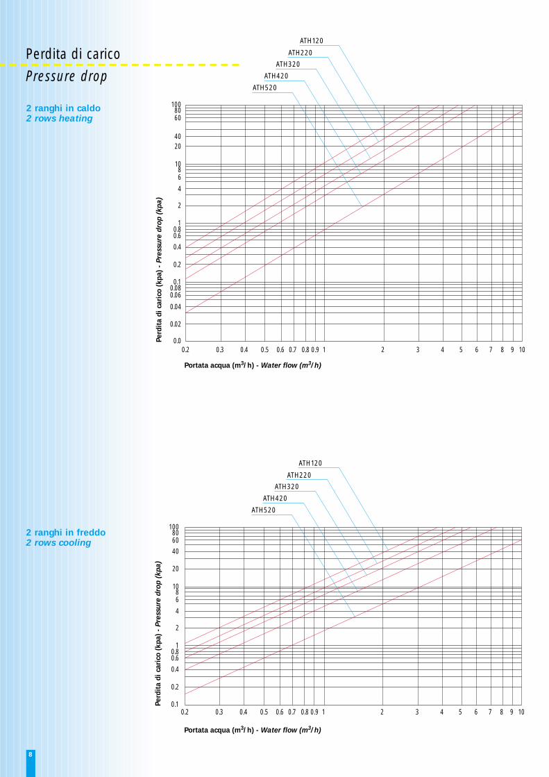
ATH120
ATH220
ATH320
ATH420
ATH520
0.2 0.3 0.4 0.5 0.6 0.7 0.8 0.9 1 2 3 4 5 6 7 8 9 100.0
0.02
0.04
0.060.080.1
0.2
0.4
0.60.8
1
2
4
68
10
2040
6080
100
Perd
ita
di c
aric
o (k
pa)
- Pr
essu
re d
rop
(kpa
)
ATH120
ATH220
ATH320
ATH420
ATH520
0.2 0.3 0.4 0.5 0.6 0.7 0.8 0.9 1 2 3 4 5 6 7 8 9 100.1
0.2
0.4
0.60.8
1
2
4
68
10
20
406080
100
Perd
ita
di c
aric
o (k
pa)
- Pr
essu
re d
rop
(kpa
)
Portata acqua (m3/h) - Water flow (m3/h)
Portata acqua (m3/h) - Water flow (m3/h)
Perdita di caricoPressure drop
2 ranghi in caldo2 rows heating
2 ranghi in freddo2 rows cooling
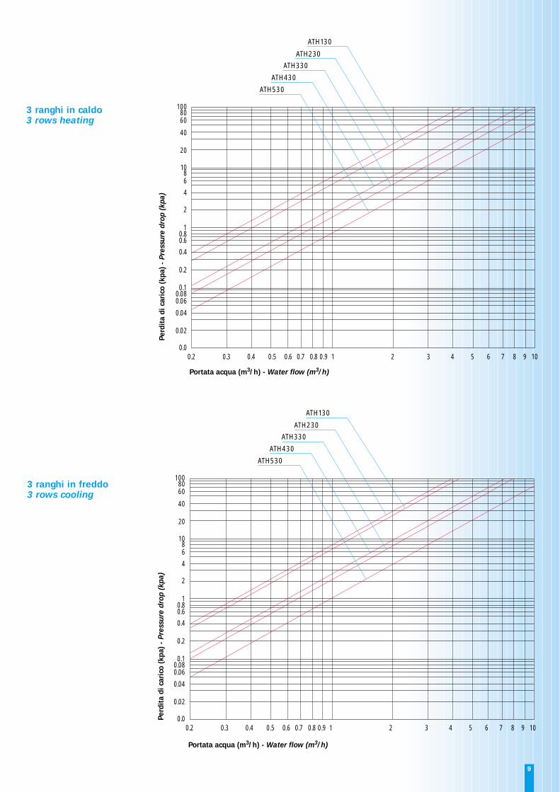
ATH130
ATH230
ATH330
ATH430
ATH530
0.2 0.3 0.4 0.5 0.6 0.7 0.8 0.9 1 2 3 4 5 6 7 8 9 100.0
0.02
0.04
0.060.080.1
0.2
0.4
0.60.8
1
2
4
68
10
20
40
6080
100
Perd
ita
di c
aric
o (k
pa)
- Pr
essu
re d
rop
(kpa
)
ATH130
ATH230
ATH330
ATH430
ATH530
0.2 0.3 0.4 0.5 0.6 0.7 0.8 0.9 1 2 3 4 5 6 7 8 9 100.0
0.02
0.04
0.060.080.1
0.2
0.4
0.60.8
1
2
4
68
10
20
40
6080
100
Perd
ita
di c
aric
o (k
pa)
- Pr
essu
re d
rop
(kpa
)
Portata acqua (m3/h) - Water flow (m3/h)
Portata acqua (m3/h) - Water flow (m3/h)
3 ranghi in caldo3 rows heating
3 ranghi in freddo3 rows cooling
9
10
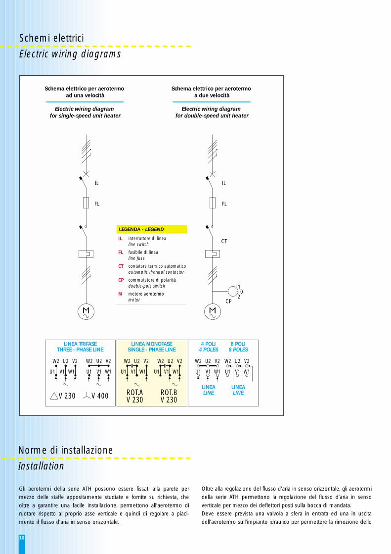
Schemi elettriciElectric wiring diagrams
IL
FL
IL
FL
CT
CP20
1
W2 U2 V2
U1 V1 W1
W2 U2 V2
U1 V1 W1
W2 U2 V2
U1 V1 W1
W2 U2 V2
U1 V1 W1
W2 U2 V2
U1 V1 W1
W2 U2 V2
U1 V1 W1
V 230 V 400 ROT.AV 230
ROT.BV 230
LINEA TRIFASETHREE - PHASE LINE
LINEA MONOFASESINGLE - PHASE LINE
4 POLI4 POLES
8 POLI8 POLES
LINEALINE
LINEALINE
Schema elettrico per aerotermo ad una velocità
Electric wiring diagram for single-speed unit heater
Schema elettrico per aerotermo a due velocità
Electric wiring diagram for double-speed unit heater
IL interruttore di linealine switch
FL fusibile di linealine fuse
CT contatore termico automaticoautomatic thermal contactor
CP commutatore di polaritàdouble-pole switch
M motore aerotermomotor
LEGENDA - LEGEND
Norme di installazioneInstallation
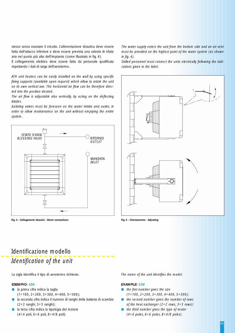
Gli aerotermi della serie ATH possono essere fissati alla parete permezzo delle staffe appositamente studiate e fornite su richiesta, cheoltre a garantire una facile installazione, permettono all’aerotermo diruotare rispetto al proprio asse verticale e quindi di regolare a piaci-mento il flusso d’aria in senso orizzontale.
Oltre alla regolazione del flusso d’aria in senso orizzontale, gli aerotermidella serie ATH permettono la regolazione del flusso d’aria in senso verticale per mezzo dei deflettori posti sulla bocca di mandata.Deve essere prevista una valvola a sfera in entrata ed una in uscita dell’aerotermo sull’impianto idraulico per permettere la rimozione dello
11
stesso senza svuotare il circuito. L’alimentazione idraulica deve esserefatta dall’attacco inferiore e deve essere prevista una valvola di sfiatoaria nel punto più alto dell’impianto (come illustrato in fig. 4). Il collegamento elettrico deve essere fatto da personale qualificatorispettando i dati di targa dell’aerotermo.
ATH unit heaters can be easily installed on the wall by using specificfixing supports (available upon request) which allow to rotate the uniton its own vertical axe. The horizontal air flow can be therefore direc-ted into the position desired.The air flow is adjustable also vertically, by acting on the deflecting blades.Isolating valves must be foreseen on the water intake and outlet, inorder to allow maintenance on the unit without emptying the entiresystem.
The water supply enters the unit from the bottom side and an air ventmust be provided on the highest point of the water system (as shownin fig. 4).Skilled personnel must connect the units electrically following the indi-cations given in the label.
Identificazione modelloIdentification of the unit
La sigla identifica il tipo di aerotermo richiesto.
ESEMPIO: 134la prima cifra indica la taglia (1=100, 2=200, 3=300, 4=400, 5=500); la seconda cifra indica il numero di ranghi della batteria di scambio(2=2 ranghi, 3=3 ranghi); la terza cifra indica la tipologia del motore (4=4 poli, 6=6 poli, 8=4/8 poli).
The name of the unit identifies the model.
EXAMPLE: 134the first number gives the size (1=100, 2=200, 3=300, 4=400, 5=500); the second number gives the number of rows of the heat exchanger (2=2 rows, 3=3 rows); the third number gives the type of motor (4=4 poles, 6=6 poles, 8=4/8 poles).
SFIATO D’ARIABLEEDING VALVE RITORNO
OUTLET
MANDATAINLET
Fig. 4 - Collegamenti idraulici · Water connections Fig. 5 - Orientamento · Adjusting
Via Malignani, 12 - Z. I. Vallenoncello - 33170 Pordenone - ItaliaTelefono 0434/572552 r.a. - Fax 0434/28667e-mail: [email protected] - [email protected]
Jann
a/Pn
- St
ampa
Ant
iga
Per la continua evoluzione del programmadi innovazione e di miglioramenti tecnolo-gici, le descrizioni, i dati e le illustrazionidevono intendersi indicativi a tutti gli effettie possono essere soggetti a cambiamentisenza preavviso.
As programs and technologies are alwaysimproving, descriptions, data and drawingsmust be intended as merely indicative andcan be modified without any notice.