A 3024 - A 3124 A 5024 - A 5124 - peiter.pl · • Durante l’utilizzo di un selettore o di un...
48
119DU92 Русский RU Français FR Engli sh E N I t aliano I T MANUALE D’INSTALLAZIONE A 3024 - A 3124 A 5024 - A 5124 AUTOMAZIONE ESTERNA PER CANCELLI A BATTENTE
-
Upload
truongtuong -
Category
Documents
-
view
213 -
download
0
Transcript of A 3024 - A 3124 A 5024 - A 5124 - peiter.pl · • Durante l’utilizzo di un selettore o di un...

119DU92
Русский RU
Français FR
English EN
Italiano IT
MANUALE D’INSTALLAZIONE
A 3024 - A 3124 A 5024 - A 5124
AUTOMAZIONE ESTERNA PER CANCELLI A BATTENTE
4 x 1,5
2 x 1 - TX
4 x 1
2 x 1,53 x 1,5
2 x 1
- RX
T R
G58
4 x 1,5
Pag
. 22
-
Cod
ice
man
ual
e: 1
19
DU
92
IT11
9D
U9
2IT
ver
. 2
. 2
0
1/2
015
© C
AM
E S
.p.A
. -
I dat
i e le
info
rmazi
oni i
ndic
ate
in q
ues
to m
anual
e so
no
da
rite
ner
si s
usc
ettibili
di m
odific
a in
qual
sias
i mom
ento
e s
enza
obblig
o di p
reav
viso
da
par
te d
i CA
ME
S.p
.A.
ITA
LIA
NO
Pericolo di schiacciamento mani
Pericolo parti in tensione
Divieto di transito durante la manovra
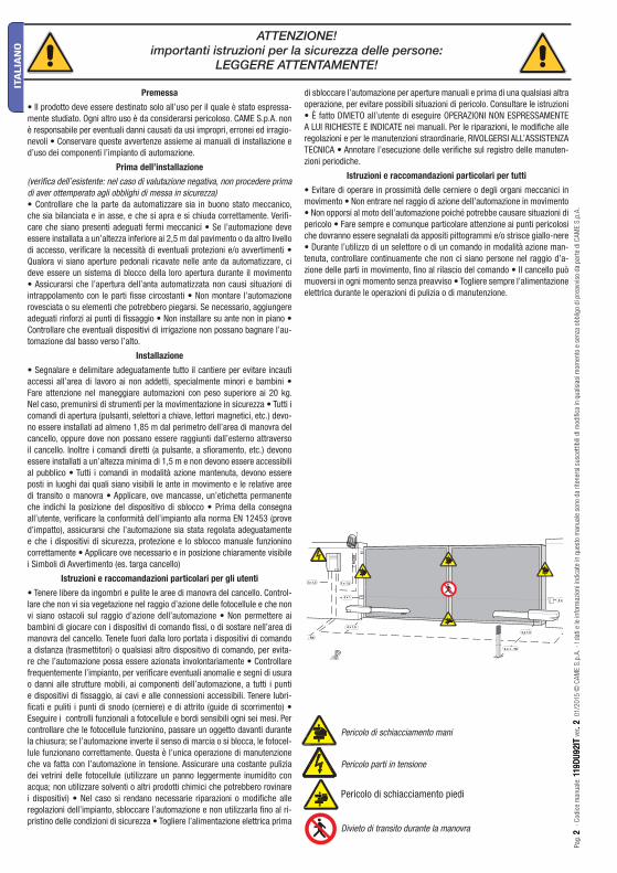
ATTENZIONE!importanti istruzioni per la sicurezza delle persone:
LEGGERE ATTENTAMENTE!
Premessa
• Il prodotto deve essere destinato solo all’uso per il quale è stato espressa-mente studiato. Ogni altro uso è da considerarsi pericoloso. CAME S.p.A. non è responsabile per eventuali danni causati da usi impropri, erronei ed irragio-nevoli • Conservare queste avvertenze assieme ai manuali di installazione e d’uso dei componenti l’impianto di automazione.
Prima dell’installazione
(verifi ca dell’esistente: nel caso di valutazione negativa, non procedere prima di aver ottemperato agli obblighi di messa in sicurezza)• Controllare che la parte da automatizzare sia in buono stato meccanico, che sia bilanciata e in asse, e che si apra e si chiuda correttamente. Verifi -care che siano presenti adeguati fermi meccanici • Se l’automazione deve essere installata a un’altezza inferiore ai 2,5 m dal pavimento o da altro livello di accesso, verifi care la necessità di eventuali protezioni e/o avvertimenti • Qualora vi siano aperture pedonali ricavate nelle ante da automatizzare, ci deve essere un sistema di blocco della loro apertura durante il movimento • Assicurarsi che l’apertura dell’anta automatizzata non causi situazioni di intrappolamento con le parti fi sse circostanti • Non montare l’automazione rovesciata o su elementi che potrebbero piegarsi. Se necessario, aggiungere adeguati rinforzi ai punti di fi ssaggio • Non installare su ante non in piano • Controllare che eventuali dispositivi di irrigazione non possano bagnare l’au-tomazione dal basso verso l’alto.
Installazione
• Segnalare e delimitare adeguatamente tutto il cantiere per evitare incauti accessi all’area di lavoro ai non addetti, specialmente minori e bambini • Fare attenzione nel maneggiare automazioni con peso superiore ai 20 kg. Nel caso, premunirsi di strumenti per la movimentazione in sicurezza • Tutti i comandi di apertura (pulsanti, selettori a chiave, lettori magnetici, etc.) devo-no essere installati ad almeno 1,85 m dal perimetro dell’area di manovra del cancello, oppure dove non possano essere raggiunti dall’esterno attraverso il cancello. Inoltre i comandi diretti (a pulsante, a sfi oramento, etc.) devono essere installati a un’altezza minima di 1,5 m e non devono essere accessibili al pubblico • Tutti i comandi in modalità azione mantenuta, devono essere posti in luoghi dai quali siano visibili le ante in movimento e le relative aree di transito o manovra • Applicare, ove mancasse, un’etichetta permanente che indichi la posizione del dispositivo di sblocco • Prima della consegna all’utente, verifi care la conformità dell’impianto alla norma EN 12453 (prove d’impatto), assicurarsi che l’automazione sia stata regolata adeguatamente e che i dispositivi di sicurezza, protezione e lo sblocco manuale funzionino correttamente • Applicare ove necessario e in posizione chiaramente visibile i Simboli di Avvertimento (es. targa cancello)
Istruzioni e raccomandazioni particolari per gli utenti
• Tenere libere da ingombri e pulite le aree di manovra del cancello. Control-lare che non vi sia vegetazione nel raggio d’azione delle fotocellule e che non vi siano ostacoli sul raggio d’azione dell’automazione • Non permettere ai bambini di giocare con i dispositivi di comando fi ssi, o di sostare nell’area di manovra del cancello. Tenete fuori dalla loro portata i dispositivi di comando a distanza (trasmettitori) o qualsiasi altro dispositivo di comando, per evita-re che l’automazione possa essere azionata involontariamente • Controllare frequentemente l’impianto, per verifi care eventuali anomalie e segni di usura o danni alle strutture mobili, ai componenti dell’automazione, a tutti i punti e dispositivi di fi ssaggio, ai cavi e alle connessioni accessibili. Tenere lubri-fi cati e puliti i punti di snodo (cerniere) e di attrito (guide di scorrimento) • Eseguire i controlli funzionali a fotocellule e bordi sensibili ogni sei mesi. Per controllare che le fotocellule funzionino, passare un oggetto davanti durante la chiusura; se l’automazione inverte il senso di marcia o si blocca, le fotocel-lule funzionano correttamente. Questa è l’unica operazione di manutenzione che va fatta con l’automazione in tensione. Assicurare una costante pulizia dei vetrini delle fotocellule (utilizzare un panno leggermente inumidito con acqua; non utilizzare solventi o altri prodotti chimici che potrebbero rovinare i dispositivi) • Nel caso si rendano necessarie riparazioni o modifi che alle regolazioni dell’impianto, sbloccare l’automazione e non utilizzarla fi no al ri-pristino delle condizioni di sicurezza • Togliere l’alimentazione elettrica prima
di sbloccare l’automazione per aperture manuali e prima di una qualsiasi altra operazione, per evitare possibili situazioni di pericolo. Consultare le istruzioni • È fatto DIVIETO all’utente di eseguire OPERAZIONI NON ESPRESSAMENTE A LUI RICHIESTE E INDICATE nei manuali. Per le riparazioni, le modifi che alle regolazioni e per le manutenzioni straordinarie, RIVOLGERSI ALL’ASSISTENZA TECNICA • Annotare l’esecuzione delle verifi che sul registro delle manuten-zioni periodiche.
Istruzioni e raccomandazioni particolari per tutti
• Evitare di operare in prossimità delle cerniere o degli organi meccanici in movimento • Non entrare nel raggio di azione dell’automazione in movimento • Non opporsi al moto dell’automazione poiché potrebbe causare situazioni di pericolo • Fare sempre e comunque particolare attenzione ai punti pericolosi che dovranno essere segnalati da appositi pittogrammi e/o strisce giallo-nere • Durante l’utilizzo di un selettore o di un comando in modalità azione man-tenuta, controllare continuamente che non ci siano persone nel raggio d’a-zione delle parti in movimento, fi no al rilascio del comando • Il cancello può muoversi in ogni momento senza preavviso • Togliere sempre l’alimentazione elettrica durante le operazioni di pulizia o di manutenzione.
Pericolo di schiacciamento piedi

12
3
4
Pag
. 33
-
Cod
ice
man
ual
e: 1
19
DU
92
IT11
9D
U9
2IT
ver
. 2
. 2
0
1/2
015
© C
AM
E S
.p.A
. -
I dat
i e le
info
rmazi
oni i
ndic
ate
in q
ues
to m
anual
e so
no
da
rite
ner
si s
usc
ettibili
di m
odific
a in
qual
sias
i mom
ento
e s
enza
obblig
o di p
reav
viso
da
par
te d
i CA
ME
S.p
.A.
ITA
LIA
NO
Alimentazione quadro: 230 A.C. 50/60HzAlimentazione motore: 24V D.C. 50/60HzAssorbimento max.: 10A Potenza: 120WTempo di apertura (90°): regolabile
Rapporto di riduzione: 1/36Intermittenza di lavoro: servizio intensivoGrado di protezione: IP44Peso: 10 kgTemperatura d’esercizio:
4.1 Motoriduttore
Questo prodotto è progettato e costruito dalla CAME S.p.A. in conformità alle vigenti norme di sicurezza. Il motoriduttore è costituito da due semigusci in fusione di alluminio al cui interno si trova il motoriduttore e i fi necorsa - con elettroblocco - e un sistema di riduzione epicicloidale con vite senza fi ne.
4 Descrizione
2.1 Destinazione d’uso
1 Legenda simboli
Questo simbolo segnala parti da leggere con attenzione.
Questo simbolo segnala parti riguardanti alla sicurezza.
Questo simbolo segnala le note da comunicare all’utente.
2 Destinazione e limiti d’impiego
Il motoriduttore ATI 24V è destinato per automatizzare cancelli battenti di tipo residenziale e condominiale anche per servizio intensivo.
3 Riferimenti normativi
2.2 Limiti d’impiegoOgni uso, diverso da quanto sopra descritto ed installazioni in modalità diverse da quanto esposto nel seguente manuale tecnico, sono da considerarsi vietate.
4.2 Informazioni tecniche
CAME S.p.A. è una azienda certificata per il sistema di gestione della qualità aziendale ISO 9001 e di gestione ambientale ISO 14001.Il prodotto in oggetto è conforme alle seguenti normative: vedi dichiarazione di conformità.
4.3 Descrizione delle parti
1) Motoriduttore2) Staff a di testa3) Snodo di coda4) Staff a di coda

A 3024 - A 3124
A 5024 - A 5124
Pag
. 44
-
Cod
ice
man
ual
e: 1
19
DU
92
IT11
9D
U9
2IT
ver
. 2
. 2
0
1/2
015
© C
AM
E S
.p.A
. -
I dat
i e le
info
rmazi
oni i
ndic
ate
in q
ues
to m
anual
e so
no
da
rite
ner
si s
usc
ettibili
di m
odific
a in
qual
sias
i mom
ento
e s
enza
obblig
o di p
reav
viso
da
par
te d
i CA
ME
S.p
.A.
ITA
LIA
NO
4.4 Misure d’ingombro
Misure in mmLarghezza Anta Peso anta
m kg
2.00 800
2.50 600
3.00 400
Larghezza Anta Peso anta
m kg
2.00 1000
2.50 800
3.00 600
4.00 500
5.00 400
Prima di procedere all’installazione dell’automatismo è necessario:
• Che la struttura del cancello sia adeguatamente robusta, le cerniere siano effi cienti e che non vi sia attrito tra parti fi sse e mobili;• Che la misura C non sia superiore al valore indicato nella Tab. 3, pag. 4. In tal caso è necessario intervenire sul pilastro in modo da
raggiungere tale misura;• Il percorso dei cavi elettrici secondo le disposizioni di comando e sicurezza;• Che ci sia una battuta d’arresto meccanico in chiusura (ben fi ssata al suolo) per evitare l’oltrecorsa anta/motoriduttore.• Connessioni interne all’involucro eseguite per la continuità del circuito di protezione sono ammesse, purchè provviste d’isolamento
supplementare rispetto ad altre parti conduttrici interne;• Predisporre tubazioni e canaline adeguate per il passaggio dei cavi elettrici garantendone la protezione contro il danneggiamento
meccanico.
L’ installazione deve essere eff ettuata da personale qualifi cato ed esperto e nel pieno rispetto delle normative vigenti.
5 Installazione
5.1 Verifiche preliminari
Corsa
Corsa
Pilastro
AntaBattuta d’arresto
Cerniera
Nei cancelli a battente è sempre consigliata l’installazione di una elettroserratura, allo scopo di assicurare un’affidabile chiusura.Con le automazioni reversibili, Came ne raccomanda l’installazione per garantire la sicurezza anti-intrusione.Con le automazioni irreversibili, l’installazione è obbligatoria con ante superiori a 4 m.

2 x 1 - TX
4 x 1
2 x 1,53 x 1,5
2 x 1
3 x 1230 V
4 x 1 - RX
T R
G58
* *1
1
2 34
4 5
44
67
8
*
Pag
. 55
-
Cod
ice
man
ual
e: 1
19
DU
92
IT11
9D
U9
2IT
ver
. 2
. 2
0
1/2
015
© C
AM
E S
.p.A
. -
I dat
i e le
info
rmazi
oni i
ndic
ate
in q
ues
to m
anual
e so
no
da
rite
ner
si s
usc
ettibili
di m
odific
a in
qual
sias
i mom
ento
e s
enza
obblig
o di p
reav
viso
da
par
te d
i CA
ME
S.p
.A.
ITA
LIA
NO
5.2 Attrezzi e materiali
Assicurarsi di avere tutti gli strumenti ed il materiale necessario, per effettuare l’installazione nella massima sicurezza, secondo le normative vigenti. Di seguito in figura l’attrezzatura minima per l’installatore.
N.B. La valutazione della sezione dei cavi con lunghezza diversa dai dati in tabella, deve essere considerata sulla base degli eff ettivi assorbimenti dei dispositivi collegati, secondo le prescrizioni indicate dalla normativa CEI EN 60204-1.Per i collegamenti che prevedano più carichi sulla stessa linea (sequenziali), il dimensionamento a tabella deve essere riconsiderato sulla base degli assorbimenti e distanze eff ettivi.
5.3 Tipologia cavi e spessori minimi
Collegamento Tipologia cavo Lunghezza cavo1 < 10 m
Lunghezza cavo10 < 20 m
Lunghezza cavo20 < 30 m
Alimentazione quadro 230V
FROR CEI 20-22 CEI EN
50267-2-1
3G x 1,5 mm2 3G x 2,5 mm2 3G x 4 mm2
Lampeggiatore 24V 2 x 0,5 mm2 2 x 1 mm2 2 x 1,5 mm2
Fotocellule TX 2 x 0,5 mm2 2 x 0.5 mm2 2 x 0,5 mm2
Fotocellule RX 4 x 0,5 mm2 4 x 0,5 mm2 4 x 0,5 mm2
Alimentazione accessori 24V 2 x 0,5 mm2 2 x 0,5 mm2 2 x 1 mm2
Pulsanti di comando 2 x 0,5 mm2 2 x 0,5 mm2 2 x 0,5 mm2
Finecorsa 3 x 0,5 mm2 3 x 1 mm2 3 x 1,5 mm2
Collegamento Encoder 2402C 22AWG max. 30 m
Collegamento antenna RG58 max. 50 m
1) Motoriduttore2) Quadro comando3) Ricevitore radio4) Fotocellule di sicurezza
5.4 Impianto tipo
Cavi di collegamento microinterruttori:5 x 1 mm2
Cavi di alimentazione motore:2 x 1,5 mm2 fino a 20 m;2 x 2,5 mm2 fino a 30 m.
5) Selettore a chiave6) Antenna7) Lampeggiatore di movimento8) Trasmettitore radio

Pag
. 66
-
Cod
ice
man
ual
e: 1
19
DU
92
IT11
9D
U9
2IT
ver
. 2
. 2
0
1/2
015
© C
AM
E S
.p.A
. -
I dat
i e le
info
rmazi
oni i
ndic
ate
in q
ues
to m
anual
e so
no
da
rite
ner
si s
usc
ettibili
di m
odific
a in
qual
sias
i mom
ento
e s
enza
obblig
o di p
reav
viso
da
par
te d
i CA
ME
S.p
.A.
ITA
LIA
NO
Le applicazioni che seguono sono solo esempi, in quanto lo spazio per il fissaggio dell’automazione e gli accessori varia a seconda degli ingombri e pertanto spetta all’installatore scegliere la soluzione più idonea.
5.5 Montaggio
Applicare al pilastro la piastra di fissaggio con la staffa di coda (fig. 1) rispettando le quote A e B (Tab. 3) tra l’asse della cerniera e il foro centrale della staffa. La staffa di coda è dotata di ulteriori forature per variare l’angolo di apertura del cancello.N.B.: aumentando la misura B diminuisce l’angolo di apertura con conseguente diminuzione della velocità periferica e aumento della spinta motore sull’anta. Aumentando la misura A aumenta l’angolo di apertura con conseguente aumento della velocità periferica e diminuzione della spinta motore sull’anta.
A cancello chiuso applicare sull’anta la piastra di fissaggio, accertandosi che la staffa di testa sia in asse orizzontale con la staffa di coda e rispettando la misura E.
Pilastro
Cerniera Anta pos. chiusa
Tab. 3
Piastra di fi ssaggio
Staff a di coda
Boccola
Snodo di coda
Livellare la staff a
Piastra di fi ssaggio
Staff a di testa
Ante fino a 3 m
Apertura A
mmB
mmC max mm
Emm
90° 130 130 60 720
120° 130 110 50 720
Ante fino a 5 m
Apertura A
mmB
mmC max mm
Emm
90° 200 200 120 920
130° 200 140 70 920

M8x10
M8x50
N M F FA RC R RA
Pag
. 77
-
Cod
ice
man
ual
e: 1
19
DU
92
IT11
9D
U9
2IT
ver
. 2
. 2
0
1/2
015
© C
AM
E S
.p.A
. -
I dat
i e le
info
rmazi
oni i
ndic
ate
in q
ues
to m
anual
e so
no
da
rite
ner
si s
usc
ettibili
di m
odific
a in
qual
sias
i mom
ento
e s
enza
obblig
o di p
reav
viso
da
par
te d
i CA
ME
S.p
.A.
ITA
LIA
NO
Morsettiera motore
Morsettiera quadro comando
Motore 1 N1 M1 C Fa1 Rc1 C Ra1Motore 2 N2 M2 C Fa2 Rc2 C Ra2 ZL 19N
N - MCollegamento motore
F - FaMicrointerruttore di finecorsa motore in apertura
R - RcMicrointerrruttore di rallentamento motore in chiusura
R - RaMicrointerruttore di rallentamento motore in apertura
Svitare le due viti di fi ssaggio del carter ed estrarlo.
Svitare le due viti di fi ssaggio dello stelo ed estrarlo.
N.B: è consigliabile lubrifi care (con grasso neutro) la vite senza fi ne e la boccola al momento dell’installazione.
Procedere al montaggio del motoriduttore alle due staff e.
Dado M8 autobloccanteVite senza fi ne
5.6 Collegamenti elettrici al quadro comando ZL 19N
Carter
Stelo

100
mm
Pag
. 88
-
Cod
ice
man
ual
e: 1
19
DU
92
IT11
9D
U9
2IT
ver
. 2
. 2
0
1/2
015
© C
AM
E S
.p.A
. -
I dat
i e le
info
rmazi
oni i
ndic
ate
in q
ues
to m
anual
e so
no
da
rite
ner
si s
usc
ettibili
di m
odific
a in
qual
sias
i mom
ento
e s
enza
obblig
o di p
reav
viso
da
par
te d
i CA
ME
S.p
.A.
ITA
LIA
NO
IN APERTURA:
Sbloccare il motoriduttore e portare l’anta in posizione di apertura massima desiderata; svitare le viti di fissaggio del gruppo microinterruttori di rallentamento e di stop in apertura.
Far scorrere il gruppo microinterruttori sull’asta porta microinterruttore fino a raggiungere l’inserimento dello stesso mediante contatto sulla slitta azionamento microinterruttore.
Fissare il gruppo microinterruttori agendo sulle rispettive viti.
IN CHIUSURA:
Portare l’anta a non oltre 100 mm dalla battuta d’arresto in chiusura (part. B).Svitare le viti di fissaggio del gruppo microinterruttore di rallentamento in chiusura.
Far scorrere il gruppo microionterruttore sull’asta portamicrointerruttore fino a raggiungere l’inserimento dello stesso mediante contatto sulla lista azionamento microinterruttore.
Fissare il gruppo microinterruttore agendo sulle rispettive viti.
5.7 Regolazione microinterruttori di rallentamento in apertura e in chiusura
Battuta d’arresto
Gruppo microinterruttore di rallentamento e di stop in apertura
Supporto cavo
Asta porta microinterruttore
Microinterruttore di rallentamento in chiusura
Vite senza fine
Slitta azionamento microinterruttore
MadreviteViti di fissaggio
Madrevite

CAME
180
Pag
. 99
-
Cod
ice
man
ual
e: 1
19
DU
92
IT11
9D
U9
2IT
ver
. 2
. 2
0
1/2
015
© C
AM
E S
.p.A
. -
I dat
i e le
info
rmazi
oni i
ndic
ate
in q
ues
to m
anual
e so
no
da
rite
ner
si s
usc
ettibili
di m
odific
a in
qual
sias
i mom
ento
e s
enza
obblig
o di p
reav
viso
da
par
te d
i CA
ME
S.p
.A.
ITA
LIA
NO
Sbloccare il motoriduttore e portare l’anta in posizione di apertura massima desiderata; svitare le viti di fissaggio del gruppo microinterruttore.
Far scorrere il gruppo microinterruttore sull’asta porta microinterruttore fino a raggiungere l’inserimento dello stesso mediante contatto sulla slitta azionamento gruppo microinterruttore.
Fissare il microinterruttore agendo sulle rispettive viti.
PER SBLOCCARE:
L’operazione di sblocco va effettuata a motore fermo:
1) sollevare lo sportellino;
2) inserire e girare la chiave che istantaneamente sblocca l’anta;
3) spingere o tirare l’anta manualmente.
Per bloccare nuovamente l’anta è sufficiente reinserire e girare la chiave.
5.8 Regolazione microinterruttore STOP in apertura
Asta porta - microinterruttore
Slitta azionamento microinterruttore
Vite senza fine
Madrevite
Vite di fissaggio
Gruppo microinterruttore
5.9 Sblocco a chiave personalizzata
Sportellino
Chiave

A
B
E
N1 M1 F FA1 RC1 R1 RA1
N2 M2 F FA1 RC2 R2 RA2
N M F FA RC R RA
A 3024 - A 3124 A 5024 - A 5124
A 130 mm 200 mm
B 130 mm 200 mm
E 720 mm 920 mm
Pag
. 1
01
0 -
Cod
ice
man
ual
e: 1
19
DU
92
IT11
9D
U9
2IT
ver
. 2
. 2
0
1/2
015
© C
AM
E S
.p.A
. -
I dat
i e le
info
rmazi
oni i
ndic
ate
in q
ues
to m
anual
e so
no
da
rite
ner
si s
usc
ettibili
di m
odific
a in
qual
sias
i mom
ento
e s
enza
obblig
o di p
reav
viso
da
par
te d
i CA
ME
S.p
.A.
ITA
LIA
NO
5.10 Applicazione per aperture verso l’esterno
TAB. A
Esterno
Interno
Staffa supplementare
- Rilevare le quote A e B (Tab. 4).
- Fissare la staffa di coda integrandola con una staffa supplementare e applicarla al pilastro.
- Aprire il cancello (max 90°), rilevare la quota E (Tab. 4) e fissare all’anta la staffa di testa.
- Procedere ai collegamenti elettrici come da figura.
- Riposizionare e regolare il microinterruttore di apertura.
Morsettiera motore
Morsettiera quadro comando
Motore 1
Motore 2
7 Manutenzione
7.1 Manutenzione periodica
☞ Prima di qualsiasi operazione di manutenzione, togliere la tensione, per evitare possibili situazioni di pericolo causate da accidentali movimentazioni dell’automazione.Lubrificare i punti di snodo con del grasso, ogni qual volta si manifestino vibrazioni anomale e cigolii, come rappresentato nel disegno.

Pag
. 11
11
-
Cod
ice
man
ual
e: 1
19
DU
92
IT11
9D
U9
2IT
ver
. 2
. 2
0
1/2
015
© C
AM
E S
.p.A
. -
I dat
i e le
info
rmazi
oni i
ndic
ate
in q
ues
to m
anual
e so
no
da
rite
ner
si s
usc
ettibili
di m
odific
a in
qual
sias
i mom
ento
e s
enza
obblig
o di p
reav
viso
da
par
te d
i CA
ME
S.p
.A.
ITA
LIA
NO
MALFUNZIONAMENTI POSSIBILI CAUSE VERIFICHE E RIMEDI
Il cancello non apre e non chiude
• Manca alimentazione• Il motoriduttore è sbloccato• Il trasmettitore ha la batteria scarica• Il trasmettitore è rotto• Pulsante di stop è inceppato o rotto• Pulsante di apertura/chiusura o selettore a chiave sono inceppati
• Verificare la presenza di rete• Rivolgersi all’assistenza• Sostituire le pile• Rivolgersi all’assistenza• Rivolgersi all’assistenza• Rivolgersi all’assistenza
Il cancello apre ma non chiude
• Le fotocellule sono sollecitate • Verificare pulizia e corretto funzionamento delle fotocellule• Rivolgersi all’assistenza
Non funziona il lampeggiatore
• Lampadina bruciata • Rivolgersi all’assistenza
7.2 Risoluzione dei problemi
8 Manutenzione
Data Annotazioni Firma
Registro manutenzione periodico a cura dell’utente (ogni 6 mesi)
8.1 Manutenzione straordinaria
Timbro installatore Nome operatore
Data intervento
Firma tecnico
Firma committente
Intervento effettuato _______________________________________________________________________________________________________________________________________________________________________________________________________________________________________________________________________________________
La seguente tabella è destinata alla registrazione degli interventi di manutenzione straordinaria, di riparazione e di miglioramento, eseguiti da ditte esterne specializzate.
N.B. Gli interventi di manutenzione straordinaria devono essere effettuati da tecnici specializzati.
Timbro installatore Nome operatore
Data intervento
Firma tecnico
Firma committente
Intervento effettuato _______________________________________________________________________________________________________________________________________________________________________________________________________________________________________________________________________________________
Registro manutenzione straordinaria

www. came.comwww. came.com
IT • Per ogni ulteriore informazione su azienda, prodotti e assistenza nella vostra lingua:EN • For any further information on company, products and assistance in your language:
FR • Pour toute autre information sur la société, les produits et l’assistance dans votre langue :DE • Weitere Infos über Unternehmen, Produkte und Kundendienst bei:
ES • Para cualquier información sobre la empresa, los productos y asistencia en su idioma:NL • Voor meer informatie over het bedrijf, de producten en hulp in uw eigen taal:
PT • Para toda e qualquer informação acerca da empresa, de produtos e assistência técnica, em sua língua:PL • Wszystkie inne informacje dotyczące fi rmy, produktów oraz usług i pomocy technicznej w Waszym języku znajdują się na stronie:RU • Для получения дополнительной информации о компании, продукции и сервисной поддержке на вашем языке:
Pag
. 1
21
2 -
Cod
ice
man
ual
e: 1
19
DU
92
IT11
9D
U9
2IT
ver
. 2
. 2
0
1/2
015
© C
AM
E S
.p.A
. -
I dat
i e le
info
rmazi
oni i
ndic
ate
in q
ues
to m
anual
e so
no
da
rite
ner
si s
usc
ettibili
di m
odific
a in
qual
sias
i mom
ento
e s
enza
obblig
o di p
reav
viso
da
par
te d
i CA
ME
S.p
.A.
ITA
LIA
NO
Timbro installatore Nome operatore
Data intervento
Firma tecnico
Firma committente
Intervento effettuato _______________________________________________________________________________________________________________________________________________________________________________________________________________________________________________________________________________________
CAME S.P.A. implementa all’interno dei propri stabilimenti un Sistema di Gestione Ambientale certificato e conforme alla norma UNI EN ISO 14001 a garanzia del rispetto e della tutela dell’ambiente.Vi chiediamo di continuare l’opera di tutela dell’ambiente, che CAME considera uno dei fondamenti di sviluppo delle proprie strategie operative e di mercato, semplicemente osservando brevi indicazioni in materia di smaltimento:
SMALTIMENTO DELL’IMBALLOI componenti dell’imballo (cartone, plastiche etc.) sono assimilabili ai rifiuti solidi urbani e possono essere smaltiti senza alcuna difficoltà, semplicemente effettuando la raccolta differenziata per il riciclaggio.Prima di procedere è sempre opportuno verificare le normative specifiche vigenti nel luogo d’installazione.NON DISPERDERE NELL’AMBIENTE!
SMALTIMENTO DEL PRODOTTOI nostri prodotti sono realizzati con materiali diversi. La maggior parte di essi (alluminio, plastica, ferro, cavi elettrici) è assimilabile ai rifiuti solidi e urbani. Possono essere riciclati attraverso la raccoltae lo smaltimento differenziato nei centri autorizzati. Altri componenti (schede elettroniche, batterie dei radiocomandi etc.) possono invece contenere sostanze inquinanti. Vanno quindi rimossi e consegnati a ditte autorizzate al recupero e allo smaltimento degli stessi.Prima di procedere è sempre opportuno verificare le normative specifiche vigenti nel luogo di smaltimento.NON DISPERDERE NELL’AMBIENTE!
9 Dismissione e smaltimento
10 Dichiarazione
Dichiarazione - CAME S.p.A. dichiara che questo prodotto è conforme ai requisiti essenziali e alle altre disposizioni pertinenti stabilite dalla direttiva 2006/42/CE e 2004/108/CE.Su richiesta è disponibile la copia conforme all’originale della dichiarazione di conformità.
INSTALLATION MANUAL
A 3024 - A 3124 A 5024 - A 5124
AUTOMATION FOR SWING GATES
English EN
119DU92EN
4 x 1,5
2 x 1 - TX
4 x 1
2 x 1,53 x 1,5
2 x 1
- RX
T R
G58
4 x 1,5
Pag
. 22
-
Man
ual
cod
e: 1
19
DU
92
EN
11
9D
U9
2E
N v
er. 2
2
0
1/2
015
© C
AM
E S
.p.A
. -
The
dat
a an
d in
form
atio
n re
por
ted
in t
his
inst
alla
tion
man
ual
are
susc
eptible
to
chan
ge
at a
ny
time
and
withou
t ob
ligat
ion
on C
AM
E S
.p.A
. to
not
ify
use
rs.
EN
GLIS
H
Introduction
• Use this product only for the specifi c purpose for which it is designed. Any other use is therefore improper and dangerous. CAME S.p.A. is not liable for any damage due to improper, erroneous and unreasonable use • Keep these warnings together with the installation and users' manual for the automation system.
Before installing
(check what's there: if you fi nd something wrong, proceed only after correc-ting the problem so the equipment is safe to use)• Check that the part you want to automate is in good mechanical condition, that it is balanced and aligned, and that it opens and closes properly. Make sure you have suitable mechanical stops • If the operator will be installed less than 2.5 m from the fl oor or from any other access level, check whether you need additional protections and/ or warnings • With pedestrian doors framed into the doors that will be automated, a system must be in place to block their opening during movement • Make sure the opening of the automated door leaf does not cause any trapping situations involving any surrounding fi xed parts • Do not install the operator upside down or on any elements that may bend. If necessary, add suitable reinforcements at the fastening points • Do not install on sloping ground (only install on fl at ground) • Check that any watering devices cannot wet the gearmotor from the bottom upwards.
Installation
• Properly signal and demarcate the entire site prevent any careless people from entering the works area • Be careful when handling operators that wei-gh more than 20 kg (see installation manual. If such is the case, make sure you have proper hoisting equipment. All opening commands (buttons, key selectors, magnetic card readers, and so on) must be installed at least 1.85 M from the gate's area of movement, or so that they are unreachable from the outside. Moreover, the direct commands (from buttons, swipe cards, and so on) must be installed 1.5 m high off the ground and must not be reachable by the public • All "hold-to-run" commands must be placed where the ope-rating gate leaves and transit areas are completely visible. • Apply a perma-nent label that shows the position of the release device • Before turning over the installation to the user, check that the system conforms to standards EN 12453 and EN12445 (impact testing), making sure the device has been pro-perly adjusted and that the safety and protection and release devices function properly • Where necessary apply the Warning Signs so that they are clearly visible (e.g. the gate plate)
Instructions and special recommendations for users
• Keep the barrier's areas of operations unobstructed. Check that the photo-cells are free of any vegetation blocking them, and that there are no obstacles to the free movement of the operator. Do not allow children to play with the fi xed command devices, or in the barrier's area of operation. Keep transmit-ters and any other command devices away from children, to prevent the ope-rator from being activated by mistake • Frequently check the system, to scan for any anomalies or wear and tear in the moving structures, the operator's components, all fastening points and devices, the cables and accessible con-nections. Keep any jointed parts like hinges lubricated and clean of debris and the guide-sleds free of any friction • Perform functional checks to the photocells and sensitive edges every six months. To check that the photocells work properly, wave an object in front of them during closing; if the operator inverts its direction of travel or blocks movement, then the photocells are working properly. This is the only maintenance job that can be done to the gate when it is powered up. Ensure proper cleaning of the glass on the pho-tocells (use a slightly damp cloth); do not use any solvents or other chemical products that may ruin the devices) • Should any repairs or changes to the system settings be needed, release the operator and refrain from using it until safety conditions have been restored • Cut the power off before releasing the operator for manual opening, to avoid any hazardous situations. Check in-structions • It is FORBIDDEN for users to perform ANY OPERATIONS THAT ARE NOT EXPRESSLY REQUESTED OF SAID USERS in the manuals. Any repairs, adjustments or extra-ordinary maintenance, EXCLUSIVELY CALL TECHNICAL
ASSISTANCE • Log any service jobs onto the periodic maintenance journal.
Special instructions and recommendations for everyone
• Keep away from the hinges and any moving mechanical parts • Stay out of the operating range of the operator while it is moving • Do not oppo-se the movement of the operator as this may result in danger • Always be careful around the dangerous parts, which must be properly indicated with warning signs and black and yellow stripes • When using a selector switch or a maintained-action mode command, keep checking that no persons come within the operating range of the moving parts, until the command is released • The gate may move at any moment without warning. Always cut off the main electric power supply before performing any cleaning or maintenance.
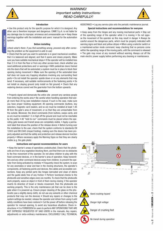
WARNING!important safety instructions:
READ CAREFULLY!
Hand crushing hazard
Danger high voltage
No transit during operation
Danger of crushing feet

12
3
4
Pag
. 33
-
Man
ual
cod
e : 1
19
DU
92
EN
11
9D
U9
2E
N v
er. 2
2
0
1/2
015
© C
AM
E S
.p.A
. -
The
dat
a an
d in
form
atio
n re
por
ted
in t
his
inst
alla
tion
man
ual
are
susc
eptible
to
chan
ge
at a
ny
time
and
withou
t ob
ligat
ion
on C
AM
E S
.p.A
. to
not
ify
use
rs.
EN
GLIS
H
Control board power supply: 230 A.C. 50/60HzMotor power supply: 24V D.C. 50/60HzMax draw.: 10A Power: 120WOpening time (90°): adjustable
Gear ratio: 1/36Duty Cycle: Intensive useProtection Rating: IP44Weight: 10 kgOperating temperature:
4.1 Gearmotor
This product is engineered and manufactured by CAME S.p.A. and complies with current safety regulations. The gearmotor is composed of two, cast aluminium half shells inside of which rest the gearmotor and endstops - with electro blocking - and an endless screw, epicycloidal gear reduction system.
4 Description
2.1 Intended use
1 Legend of symbols
This symbol tells you to read the section with particular care.
This symbol tells you that the sections concern safety issues.
This symbol tells you what to say to the end-users.
2 Intended use and restrictions
The ATI 24V gearmotor is specifi cally engineered to automate residential and condominium swing gates, even under intensive use.
3 Reference Standards
2.2 RestrictionsThe use of this product for purposes other than those described above and installation executed in a manner other than as instructed in this technical manual are prohibited.
4.2 Technical features
The company: CAME S.p.A. is ISO 9001 quality certified; is has also obtained the ISO 14001 environmental safeguarding certification. Came engineers and manufactures all of its products in Italy.This product complies with the following standards: see declaration of compliance.
4.3 Description of parts
1) Operator2) Front bracket3) Back swivel-joint4) Back bracket

A 3024 - A 3124
A 5024 - A 5124
Pag
. 44
-
Man
ual
cod
e: 1
19
DU
92
EN
11
9D
U9
2E
N v
er. 2
2
0
1/2
015
© C
AM
E S
.p.A
. -
The
dat
a an
d in
form
atio
n re
por
ted
in t
his
inst
alla
tion
man
ual
are
susc
eptible
to
chan
ge
at a
ny
time
and
withou
t ob
ligat
ion
on C
AM
E S
.p.A
. to
not
ify
use
rs.
EN
GLIS
H
4.4 Overall dimensions
Measurements in mm Gate leaf width Gate leaf weight
m kg
2.00 800
2.50 600
3.00 400
Gate leaf width Gate leaf weight
m kg
2.00 1000
2.50 800
3.00 600
4.00 500
5.00 400
Before installing, do the following:
• Make sure the structure of the gate is sturdy, the hinges work and that the is no friction between moving and non-moving parts;• That measurement C is not greater than the value shown in Tab. 3, p. 4. In this case you need to work on the pillar until said
measurement is obtained;• Make sure the path of the electrical cables complies with the command and safety instructions;• That there is a (soundly secured to the ground) mechanical stop to prevent the gate leaf/gearmotor from over extending.• Make sure that any connections inside the case (that provide continuance to the protective circuit) be fitted with extra insulation as
compared to the other conductive parts inside;• Make sure you have suitable tubing and conduits for the electrical cables to pass through and be protected against mechanical
damage.
Installation must be carried out by expert qualified personnel and in full compliance with current regulations.
5 Installation
5.1 Preliminary checks
Travel
Travel
Pillar
Gate leafEnd stop
Hinge
We suggest you always fit an electrolock onto swing gates for a more reliable closure.Fitting electrolocks onto reversible operators makes for anti-intrusion security.You must install electrolocks onto irreversible operators with gate leaves exceeding 4 m.

2 x 1 - TX
4 x 1
2 x 1,53 x 1,5
2 x 1
3 x 1230 V
4 x 1 - RX
T R
G58
* *1
1
2 34
4 5
44
67
8
*
Pag
. 55
-
Man
ual
cod
e : 1
19
DU
92
EN
11
9D
U9
2E
N v
er. 2
2
0
1/2
015
© C
AM
E S
.p.A
. -
The
dat
a an
d in
form
atio
n re
por
ted
in t
his
inst
alla
tion
man
ual
are
susc
eptible
to
chan
ge
at a
ny
time
and
withou
t ob
ligat
ion
on C
AM
E S
.p.A
. to
not
ify
use
rs.
EN
GLIS
H
5.2 Tools and materials
Make sure you have all the tools and materials you will need for the installation at hand to work in total safety and compliance with the current standards and regulations. The following figure illustrates the minimum equipment needed by the installer.
N.B.: If the cable length diff ers from that specifi ed in the table, then you must determine the proper cable diameter in the basis of the actual power draw by the connected devices and depending on the standards specifi ed in CEI EN 60204-1.For connections that require several, sequential loads, the sizes given on the table must be re-evaluated based on actual power draw and distances.
5.3 Cable list and minimum thickness
Connections Type of cable Length of cable1 < 10 m
Length of cable10 < 20 m
Length of cable20 < 30 m
Control panel power supply 230V
FROR CEI 20-22 CEI EN
50267-2-1
3G x 1,5 mm2 3G x 2,5 mm2 3G x 4 mm2
Flashing light 24V 2 x 0,5 mm2 2 x 1 mm2 2 x 1,5 mm2
Photocell transmitters 2 x 0,5 mm2 2 x 0.5 mm2 2 x 0,5 mm2
Photocell receivers 4 x 0,5 mm2 4 x 0,5 mm2 4 x 0,5 mm2
24V Accessories power supply 2 x 0,5 mm2 2 x 0,5 mm2 2 x 1 mm2
Command buttons 2 x 0,5 mm2 2 x 0,5 mm2 2 x 0,5 mm2
Endstop 3 x 0,5 mm2 3 x 1 mm2 3 x 1,5 mm2
Encoder plug 2402C 22AWG max. 30 m
Antenna connection RG58 max. 50 m
1) Operator2) Control panel3) Radio receiver4) Photocells
5) Selector switch6) Antenna7) Flashing light8) Transmitter
Wiring for microswitches: 5 x 1mm2
Power wires to motor: 2 x 1,5 mm2 up to 20 m; 2 x 2,5 mm2 up to 30 m.
5.4 Standard installation

Pag
. 66
-
Man
ual
cod
e: 1
19
DU
92
EN
11
9D
U9
2E
N v
er. 2
2
0
1/2
015
© C
AM
E S
.p.A
. -
The
dat
a an
d in
form
atio
n re
por
ted
in t
his
inst
alla
tion
man
ual
are
susc
eptible
to
chan
ge
at a
ny
time
and
withou
t ob
ligat
ion
on C
AM
E S
.p.A
. to
not
ify
use
rs.
EN
GLIS
H
The following are just example applications, given that the space for securing the operator and accessories may vary depending on the dimensions. It is thus up to the installer to choose the most suitable solution.
5.5 Mounting
Apply the anchoring plate to the pillar using the back bracket (fig. 1) making sure the A and B measurements are right (Tab. 3) between the hinge axis and central bore hole on the bracket. The back bracket has several other holes for changing the opening angle of the gate.N.B.: increasing the B measurement decreases the opening angle resulting in slower peripheral speed and greater motor thrust on the gate leaf. Increasing measurement A increases the opening angle resulting in greater peripheral speed and reduced motor thrust on the gate leaf.
With the gate closed apply the anchoring plate to the gate leaf, making sure that the front bracket is lined up horizontally with the back bracket and ensuring that measurement E is met.
Pillar
Hinge Gate leaf closed position
Tab. 3
Anchoring plate
Back bracket
Bushing
Back swivel-joint
Level the bracket
Anchoring plate
Front bracket
Gate leaves up to 3 m
Opening A
mmB
mmC max mm
Emm
90° 130 130 60 720
120° 130 110 50 720
Gate leaf up to 5 m
Opening A
mmB
mmC max mm
Emm
90° 200 200 120 920
130° 200 140 70 920

M8x10
M8x50
N M F FA RC R RA
Pag
. 77
-
Man
ual
cod
e : 1
19
DU
92
EN
11
9D
U9
2E
N v
er. 2
2
0
1/2
015
© C
AM
E S
.p.A
. -
The
dat
a an
d in
form
atio
n re
por
ted
in t
his
inst
alla
tion
man
ual
are
susc
eptible
to
chan
ge
at a
ny
time
and
withou
t ob
ligat
ion
on C
AM
E S
.p.A
. to
not
ify
use
rs.
EN
GLIS
H
Unscrew the two securing screws and remove the carter.
Unscrew the two securing screws and remove the stem.
N.B.: we suggest lubricating (using neutral grease) the endless screw and the bushing upon installation.
Begin mounting the gearmotor to the two brackets.
M8 self-locking nutEndless screw
Carter
Stem
Motor terminal block
Control panel terminal block
Motor 1 N1 M1 C Fa1 Rc1 C Ra1Motor 2 N2 M2 C Fa2 Rc2 C Ra2 ZL 19N
N - MConnection to motor
F - FaMicroswitch-limit switch of motor on aperture
R - RcMicroswitch-deceleration of motor on closure
R - RaMicroswitch-deceleration of motor in aperture
5.6 Electrical connections to the ZL19 control panel
100
mm
Pag
. 88
-
Man
ual
cod
e: 1
19
DU
92
EN
11
9D
U9
2E
N v
er. 2
2
0
1/2
015
© C
AM
E S
.p.A
. -
The
dat
a an
d in
form
atio
n re
por
ted
in t
his
inst
alla
tion
man
ual
are
susc
eptible
to
chan
ge
at a
ny
time
and
withou
t ob
ligat
ion
on C
AM
E S
.p.A
. to
not
ify
use
rs.
EN
GLIS
H
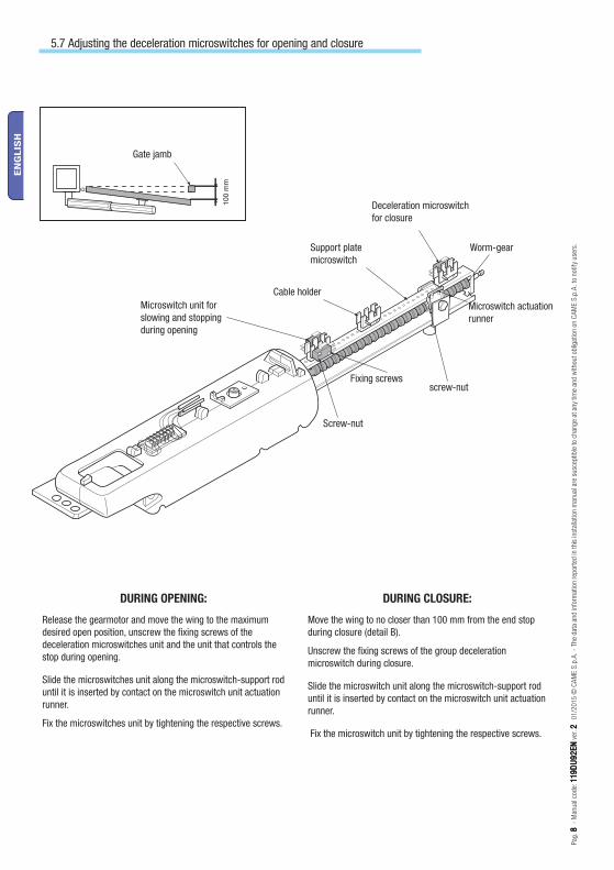
DURING OPENING:
Release the gearmotor and move the wing to the maximum desired open position, unscrew the fi xing screws of the deceleration microswitches unit and the unit that controls the stop during opening.
Slide the microswitches unit along the microswitch-support rod until it is inserted by contact on the microswitch unit actuation runner.
Fix the microswitches unit by tightening the respective screws.
DURING CLOSURE:
Move the wing to no closer than 100 mm from the end stop during closure (detail B).
Unscrew the fi xing screws of the group deceleration microswitch during closure.
Slide the microswitch unit along the microswitch-support rod until it is inserted by contact on the microswitch unit actuation runner.
Fix the microswitch unit by tightening the respective screws.
5.7 Adjusting the deceleration microswitches for opening and closure
Gate jamb
Microswitch unit for slowing and stopping during opening
Cable holder
Support plate microswitch
Deceleration microswitch for closure
Worm-gear
Microswitch actuation runner
screw-nutFixing screws
Screw-nut

CAME
180
Pag
. 99
-
Man
ual
cod
e : 1
19
DU
92
EN
11
9D
U9
2E
N v
er. 2
2
0
1/2
015
© C
AM
E S
.p.A
. -
The
dat
a an
d in
form
atio
n re
por
ted
in t
his
inst
alla
tion
man
ual
are
susc
eptible
to
chan
ge
at a
ny
time
and
withou
t ob
ligat
ion
on C
AM
E S
.p.A
. to
not
ify
use
rs.
EN
GLIS
H
RELEASING THE UNIT:
Perform this step with the motor stopped:
1) raise the access door;
2) insert and turn the key. The gate will be released immediately;
3) push or pull the gate manually.
To re-lock the gate, simply insert and turn the key.
5.9 Personalized key release
Access door
Key
Release the gearmotor and move the door to the maximum desired open position.Loosen the fi xing screws of the microswitch unit.
Slide the microswitch unit along the microswitch-support rod until it is inserted by contact on the microswitch unit actuation runner.
Fix the microswitch by tightening the respective screws.
5.8 Adjusting the STOP microswitch for the opening movement
Support plate microswitch
Microswitch actuation runner
Worm-gear
Screw-nut
Fixing screw
Microswitch unit

A
B
E
N1 M1 F FA1 RC1 R1 RA1
N2 M2 F FA1 RC2 R2 RA2
N M F FA RC R RA
A 3024 - A 3124 A 5024 - A 5124
A 130 mm 200 mm
B 130 mm 200 mm
E 720 mm 920 mm
Pag
. 1
01
0 -
Man
ual
cod
e: 1
19
DU
92
EN
11
9D
U9
2E
N v
er. 2
2
0
1/2
015
© C
AM
E S
.p.A
. -
The
dat
a an
d in
form
atio
n re
por
ted
in t
his
inst
alla
tion
man
ual
are
susc
eptible
to
chan
ge
at a
ny
time
and
withou
t ob
ligat
ion
on C
AM
E S
.p.A
. to
not
ify
use
rs.
EN
GLIS
H
5.10 Application for outside openings
TAB. A
Outside
Insoide
Supplementary bracket
- Measure the lenght of “A” and “B” (see Tab 4).
- Attach the rear bracket together with a supplementary bracket and fasten both to the column.
- Open the gate (maximum 90°) and measure “E” (see Tab 4), then fasten the front bracket to the gate.
- Make the electrical connections as shown in the fi gure.
- Re-position and adjust the opening micro-switch.
Motor terminal block
Control panel terminal block
Motor 1
Motor 2
7 Manutenzione
7.1 Manutenzione periodica
☞ Before any maintenance, disconnect power to prevent any possible dangerous situations that can be caused by accidental movement of the operator.Lubricate the pivot points with grease whenever abnormal vibrations or squeaking occurs, as shown in the drawing.

Pag
. 11
11
-
Man
ual
cod
e : 1
19
DU
92
EN
11
9D
U9
2E
N v
er. 2
2
0
1/2
015
© C
AM
E S
.p.A
. -
The
dat
a an
d in
form
atio
n re
por
ted
in t
his
inst
alla
tion
man
ual
are
susc
eptible
to
chan
ge
at a
ny
time
and
withou
t ob
ligat
ion
on C
AM
E S
.p.A
. to
not
ify
use
rs.
EN
GLIS
H
7.2 Trouble shooting
MALFUNCTIONS POSSIBLE CAUSES CHECK AND REMEDIES
The gate will not open nor close
• There is no power• The gearmotor is released• The transmitter’s batteries are run down• The transmitter is broken• The stop button is either stuck or broken• The opening/closing button or the key selector are stuck
• Check that the power is up• Call assistance• Replace batteries• Call assistance• Call assistance• Call assistance
The gate opens but will not close
• The photocells are engaged • Check that photocells are clean and in good working order• Call assistance
The flasher does not work
• The bulb is burnt • Call assistance
8 Maintenance
Date Notes Signature
Periodic maintenance log for end-user (every 6 moths)
8.1 Extra-ordinary maintenance
The following table serves to note down any extraordinary maintenance, repairs or improvements performed by specialised firms.
N.B.: Any extraordinary maintenance must be performed by specialised technicians.
Extra-ordinary maintenance log
Installer’s stamp Operator name
Date of job
Technician’s signature
Requester’s signature
Job performed __________________________________________________________________________________________________________________________________________________________________________________________
Installer’s stamp Operator name
Date of job
Technician’s signature
Requester’s signature
Job performed __________________________________________________________________________________________________________________________________________________________________________________________

www. came.comwww. came.com
IT • Per ogni ulteriore informazione su azienda, prodotti e assistenza nella vostra lingua:EN • For any further information on company, products and assistance in your language:
FR • Pour toute autre information sur la société, les produits et l’assistance dans votre langue :DE • Weitere Infos über Unternehmen, Produkte und Kundendienst bei:
ES • Para cualquier información sobre la empresa, los productos y asistencia en su idioma:NL • Voor meer informatie over het bedrijf, de producten en hulp in uw eigen taal:
PT • Para toda e qualquer informação acerca da empresa, de produtos e assistência técnica, em sua língua:PL • Wszystkie inne informacje dotyczące fi rmy, produktów oraz usług i pomocy technicznej w Waszym języku znajdują się na stronie:RU • Для получения дополнительной информации о компании, продукции и сервисной поддержке на вашем языке:
Pag
. 1
21
2 -
Man
ual
cod
e: 1
19
DU
92
EN
11
9D
U9
2E
N v
er. 2
2
0
1/2
015
© C
AM
E S
.p.A
. -
The
dat
a an
d in
form
atio
n re
por
ted
in t
his
inst
alla
tion
man
ual
are
susc
eptible
to
chan
ge
at a
ny
time
and
withou
t ob
ligat
ion
on C
AM
E S
.p.A
. to
not
ify
use
rs.
EN
GLIS
H
Installer’s stamp Operator name
Date of job
Technician’s signature
Requester’s signature
Job performed __________________________________________________________________________________________________________________________________________________________________________________________
Installer’s stamp Operator name
Date of job
Technician’s signature
Requester’s signature
Job performed __________________________________________________________________________________________________________________________________________________________________________________________
CAME S.p.A. employs a UNI EN ISO 14001 certified and compliant environmental protection system at its plants, to ensure that environmental safeguarding.We ask you to keep protecting the environment, as CAME deems it to be one of the fundamental points of its market operations strategies, by simply following these brief guidelines when disposing:
DISPOSING THE PACKING MATERIALSThe packing components (cardboard, plastic, etc.) are solid urban waste and may be disposed of without any particular difficulty, by simply separating them so that they can be recycled.Before actions it is always advisable to check the pertinent legislation where installation will take place.DO NOT DISPOSE OF IN NATURE!
DISPOSING OF THE PRODUCTOur products are made using different types of materials. The majority of them (aluminium, plastic, iron, electric cables) can be considered to be solid urban waste. They may be recycled at authorised firms. Other components (electrical circuit board, remote control batteries etc.) may contain hazardous waste. They must, thus, be removed and turned in to licensed firms for their disposal.Before acting always check the local laws on the matter.DO NOT DISPOSE OF IN NATURE!
9 Phasing out and disposal
10 Maker’s statement
Declaration - CAME S.p.A. declares that this device complies with the essential requirements and other relevant provisions established in Directives 2006/42/EC and 2004/108/EC.A true copy of the declaration of conformity is available upon request.

MANUEL POUR L’INSTALLATION
A 3024 - A 3124 A 5024 - A 5124
AUTOMATISME POUR PORTAILS BATTANTS
Français FR
119DU92FR

4 x 1,5
2 x 1 - TX
4 x 1
2 x 1,53 x 1,5
2 x 1
- RX
T R
G58
4 x 1,5
Pag
. 22
-
Cod
e m
anuel
: 11
9D
U9
2F
R11
9D
U9
2F
R v
er. 2
2
0
1/2
015
© C
AM
E S
.p.A
. -
Les
don
née
s et
les
indic
atio
ns
fourn
ies
dan
s ce
man
uel
d’in
stal
lation
peu
vent
subir d
es m
odific
atio
ns
à to
ut
mom
ent
sans
avis
pré
alab
le d
e la
par
t de
CA
ME
S.p
.A..
2
FR
AN
ÇA
IS
Avant-propos
• Ce produit ne devra être destiné qu'à l'utilisation pour laquelle il a été expressément conçu. Toute autre utilisation est à considérer comme dange-reuse. La société CAME S.p.A. décline toute responsabilité en cas d'éventuels dommages provoqués par des utilisations impropres, incorrectes et dérai-sonnables • Conserver ces instructions avec les manuels d'installation et d'utilisation des composants du système d'automatisation.
Avant l'installation
(contrôle du matériel existant : en cas d'évaluation négative, ne procéder à l'installation qu'après avoir eff ectué la mise en sécurité conforme)• S'assurer que la partie à automatiser est en bon état mécanique, qu'elle est équilibrée et alignée, et qu'elle s'ouvre et se ferme correctement. S'assurer en outre de la présence de butées mécaniques appropriées • En cas d'ins-tallation de l'automatisme à une hauteur inférieure à 2,5 m par rapport au sol ou par rapport à un autre niveau d'accès, évaluer la nécessité d'éventuels dispositifs de protection et/ou d'avertissement • En cas d'ouvertures pié-tonnières dans les vantaux à automatiser, prévoir un système de blocage de leur ouverture durant le mouvement • S'assurer que l'ouverture du vantail automatisé ne provoque aucun coincement avec les parties fi xes présentes tout autour • Ne pas installer l'automatisme dans le sens inverse ou sur des éléments qui pourraient se plier. Si nécessaire, renforcer les points de fi xation • Ne pas installer l'automatisme sur des vantaux non positionnés sur une surface plane • S'assurer que les éventuels dispositifs d'arrosage ne peuvent pas mouiller l'automatisme de bas en haut.
Installation
• Signaler et délimiter correctement le chantier afi n d'éviter tout accès impru-dent à la zone de travail de la part de personnes non autorisées, notamment des mineurs et des enfants • Manipuler les automatismes de plus de 20 kg avec une extrême prudence. Prévoir, si nécessaire, des instruments adéquats pour une manutention en toute sécurité • Toutes les commandes d'ouverture (boutons, sélecteurs à clé, lecteurs magnétiques, etc.) doivent être installées à au moins 1,85 m du périmètre de la zone d'actionnement du portail, ou bien en des points inaccessibles de l'extérieur à travers le portail. Les commandes directes (à bouton, à effl eurement, etc.) doivent en outre être installées à une hauteur minimum de 1,5 m et être inaccessibles au public • Toutes les commandes en modalité « action maintenue » doivent être positionnées dans des endroits permettant de visualiser les vantaux en mouvement ainsi que les zones correspondantes de passage ou d'actionnement • Appliquer une étiquette permanente indiquant la position du dispositif de déblocage • Avant de livrer l'installation à l'utilisateur, en contrôler la conformité à la norme EN 12453 (essais d'impact), s'assurer que l'automatisme a bien été réglé comme il faut et que les dispositifs de sécurité, de protection et de déblocage manuel fonctionnent correctement • Les Symboles d'Avertissement (ex. : plaquette portail) doivent être appliqués dans des endroits spécifi ques et bien en vue.
Instructions et recommandations particulières pour les utilisateurs
• Dégager et nettoyer les zones d'actionnement du portail. S'assurer de l'absence de toute végétation dans le rayon d'action des photocellules et de tout obstacle dans celui de l'automatisme • Ne pas permettre aux enfants de jouer avec les dispositifs de commande fi xes ou de stationner dans la zone de manœuvre du portail. Conserver hors de leur portée les dispositifs de commande à distance (émetteurs) ou tout autre dispositif de commande afi n d'éviter l'actionnement involontaire de l'automatisme • Contrôler souvent l'installation afi n de s'assurer de l'absence d'anomalies et de signes d'usure ou de dommages sur les structures mobiles, les composants de l'automa-tisme, tous les points et dispositifs de fi xation, les câbles et les connexions accessibles. Les points d'articulation (charnières) et de frottement (glissières) doivent toujours être lubrifi és et propres • Contrôler le bon fonctionnement des photocellules et des bords sensibles tous les six mois. Pour s'assurer du bon fonctionnement des photocellules, y passer devant un objet durant la fermeture ; si l'automatisme inverse le sens de la marche ou qu'il se bloque, les photocellules fonctionnent correctement. Il s'agit de l'unique opération d'entretien à eff ectuer avec l'automatisme sous tension. Assurer un net-toyage constant des verres des photocellules (utiliser un chiff on légèrement humidifi é d'eau ; ne pas utiliser de solvants ni d'autres produits chimiques qui
pourraient endommager les dispositifs) • En cas de réparations ou de modi-fi cations nécessaires des réglages de l'installation, débloquer l'automatisme et ne l'utiliser qu'après le rétablissement des conditions de sécurité • Couper le courant électrique avant de débloquer l'automatisme pour des ouvertures manuelles et avant toute autre opération afi n d'éviter les situations de dan-ger potentielles. Consulter les instructions • Il est INTERDIT à l'utilisateur d'exécuter des OPÉRATIONS QUI NE LUI AURAIENT PAS ÉTÉ EXPRESSÉMENT DEMANDÉES ET QUI NE SERAIENT PAS INDIQUÉES dans les manuels. Pour les réparations, les modifi cations des réglages et pour les entretiens curatifs, S'ADRESSER À L'ASSISTANCE TECHNIQUE • Noter l'exécution des contrôles sur le registre des entretiens périodiques.
Instructions et recommandations particulières pour tous
• Éviter d'intervenir à proximité des charnières ou des organes mécaniques en mouvement • Ne pas pénétrer dans le rayon d'action de l'automatisme lorsque ce dernier est en mouvement • Ne pas s'opposer au mouvement de l'automatisme afi n d'éviter toute situation dangereuse • Faire toujours très attention aux points dangereux qui devront être signalés par des picto-grammes et/ou des bandes jaunes et noires spécifi ques • Durant l'utilisation d'un sélecteur ou d'une commande en modalité « action maintenue », tou-jours s'assurer de l'absence de toute personne dans le rayon d'action des parties en mouvement jusqu'au relâchement de la commande • L'actionne-ment du portail peut avoir lieu à tout moment et sans préavis • Toujours cou-per le courant électrique durant les opérations de nettoyage ou d'entretien.
ATTENTION !Instructions importantes pour la sécurité des personnes :
À LIRE ATTENTIVEMENT !
Danger d'écrasement des mains
Danger parties sous tension
Passage interdit durant la manœuvre
Risque d’écrasement pour les pieds.
12
3
4
Pag
. 33
-
Cod
e m
anuel
: 11
9D
U9
2F
R11
9D
U9
2F
R v
er. 2
2
0
1/2
015
© C
AM
E S
.p.A
. -
Les
don
née
s et
les
indic
atio
ns
fourn
ies
dan
s ce
man
uel
d’in
stal
lation
peu
vent
subir d
es m
odific
atio
ns
à to
ut
mom
ent
sans
avis
pré
alab
le d
e la
par
t de
CA
ME
S.p
.A..
2
FR
AN
ÇA
IS
Alimentation armoire: 230 A.C. 50/60HzAlimentation moteur: 24V D.C. 50/60HzAbsorption max.: 10A Puissance: 120WTemps d’ouverture (90°) :réglable
Rapport de réduction: 1/36Intermittence travail : service intensifDegré de protection: IP44Poids: 10 kgTempérature de fonctionnement:
4.1 Motoréducteur
Le produit a été conçu et fabriqué par CAME S.p.A. conformément aux normes de sécurité en vigueur. Le motoréducteur est composé de deux demi-coques en fonte d’aluminium à l’intérieur desquelles sont placés le motoréducteur et les fi ns de course - avec électro blocage - et un système de réduction épicycloïdal avec vis sans fi n.
4 Description
2.1 Usage prévu
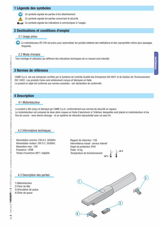
1 Légende des symboles
Ce symbole signale les parties à lire attentivement.
Ce symbole signale les parties concernant la sécurité.
Ce symbole signale les indications à communiquer à l’usager.
2 Destinations et conditions d’emploi
Le motoréducteur ATI 24V est prévu pour automatiser les portails battants des habitations et des copropriétés même pour passages fréquents.
3 Normes de référence
2.2 Mode d’emploiTout montage et utilisation qui diffèrent des indications techniques de ce manuel sont interdits.
4.2 Informations techniques
CAME S.p.A. est une entreprise certifiée par le Système de Contrôle Qualité des Entreprises ISO 9001 et de Gestion de l’Environnement ISO 14001. Les produits Came sont entièrement conçus et fabriqués en Italie.Le produit en objet est conforme aux normes suivantes : voir déclaration de conformité.
4.3 Description des parties
1) Motoréducteur2) Étrier de tête3) Articulation de queue4) Étrier de queue

A 3024 - A 3124
A 5024 - A 5124
Pag
. 44
-
Cod
e m
anuel
: 11
9D
U9
2F
R11
9D
U9
2F
R v
er. 2
2
0
1/2
015
© C
AM
E S
.p.A
. -
Les
don
née
s et
les
indic
atio
ns
fourn
ies
dan
s ce
man
uel
d’in
stal
lation
peu
vent
subir d
es m
odific
atio
ns
à to
ut
mom
ent
sans
avis
pré
alab
le d
e la
par
t de
CA
ME
S.p
.A..
2
FR
AN
ÇA
IS
4.4 Mesure d’encombrement
Mesures en mmLargeur Vantail Poids vantail
m kg
2.00 800
2.50 600
3.00 400
Largeur Vantail Poids vantail
m kg
2.00 1000
2.50 800
3.00 600
4.00 500
5.00 400
Avant de procéder au montage, il est nécessaire de:
• Vérifi er que le châssis du portail est robuste, les charnières en état de marche et qu’il n’y a pas de frottement entre les parties fi xes et les parties mobiles;
• Que la mesure C n’est pas supérieure à la valeur indiquée dans le tableau 3, page 4. Dans ce cas, il faut intervenir sur le pilier pour réussir à atteindre cette mesure.
• Le parcours des câbles électriques selon les dispositions de commande et de sécurité ;• Qu’il y a une butée d’arrêt mécanique en fermeture (bien fi xée au sol) pour éviter une course au-delà de porte/motoréducteur.• Contrôler que les connexions éventuelles à l’intérieur du conteneur (réalisées pour continuer le circuit de protection) sont équipées
d’une isolation supplémentaire par rapport aux autres parties conductrices présentes à l’intérieur ;• Prévoir des conduits et des caniveaux appropriés pour le passage des câbles électriques afin de les protéger contre tout dommage
mécanique.
Le montage doit être effectué par du personnel qualifié et expérimenté et dans le respect des normes en vigueur.
5 Installation
5.1 Contrôles préliminaires
Course
Course
Pilier
VantailButée d’arrêt
Charnière
Il convient toujours d’appliquer une serrure de verrouillage électrique sur les portails battants afin d’assurer une fermeture fiable.La société Came recommande l’installation de cette serrure en présence d’automatismes réversibles afin de garantir la sécurité anti-intrusion.En présence d’automatismes irréversibles, cette installation est obligatoire sur des vantaux de plus de 4 m.
2 x 1 - TX
4 x 1
2 x 1,53 x 1,5
2 x 1
3 x 1230 V
4 x 1 - RX
T R
G58
* *1
1
2 34
4 5
44
67
8
*
Pag
. 55
-
Cod
e m
anuel
: 11
9D
U9
2F
R11
9D
U9
2F
R v
er. 2
2
0
1/2
015
© C
AM
E S
.p.A
. -
Les
don
née
s et
les
indic
atio
ns
fourn
ies
dan
s ce
man
uel
d’in
stal
lation
peu
vent
subir d
es m
odific
atio
ns
à to
ut
mom
ent
sans
avis
pré
alab
le d
e la
par
t de
CA
ME
S.p
.A..
2
FR
AN
ÇA
IS
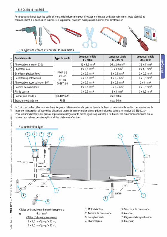
5.2 Outils et matériel
Assurez-vous d’avoir tous les outils et le matériel nécessaire pour effectuer le montage de l’automatisme en toute sécurité et conformément aux normes en vigueur. Sur la planche, quelques exemples de matériel pour l’installateur.
N.B. Au cas où les câbles auraient une longueur diff érente de celle prévue dans le tableau, on détermine la section des câbles sur la base de l’absorption eff ective des dispositifs branchés en suivant les prescriptions indiquées dans la normative CEI EN 60204-1.Pour les branchements qui prévoient plusieurs charges sur la même ligne (séquentiels), il faut revoir les dimensions indiquées sur le tableau sur la base des absorptions et des distances eff ectives.
5.3 Types de câbles et épaisseurs minimales
Branchements Type de cable Longueur câble1 < 10 m
Longueur câble10 < 20 m
Longueur câble20 < 30 m
Alimentation armoire 230V
FROR CEI 20-22 CEI EN
50267-2-1
3G x 1,5 mm2 3G x 2,5 mm2 3G x 4 mm2
Clignotant 24V 2 x 0,5 mm2 2 x 1 mm2 2 x 1,5 mm2
Émetteurs photocellules 2 x 0,5 mm2 2 x 0.5 mm2 2 x 0,5 mm2
Récepteurs photocellules 4 x 0,5 mm2 4 x 0,5 mm2 4 x 0,5 mm2
Alimentation accessoires en 24V 2 x 0,5 mm2 2 x 0,5 mm2 2 x 1 mm2
Boutons de commande 2 x 0,5 mm2 2 x 0,5 mm2 2 x 0,5 mm2
Fin de course 3 x 0,5 mm2 3 x 1 mm2 3 x 1,5 mm2
Connexion Encodeur 2402C 22AWG max. 30 m
Branchement antenne RG58 max. 50 m
1) Motoréducteur 2) Armoire de commande3) Récepteur radio4) Photocellules
5.4 Installation Type
5) Sélecteur de commande6) Antenne7) Clignotant de signalisation8) Emetteur
Câbles de branchement microinterrupteurs:5 x 1 mm2
Câbles d’alimentation moteur: 2 x 1,5 mm2 jusqu’a 20 m; 2 x 2,5 mm2 jusqu’a 30 m.

Pag
. 66
-
Cod
e m
anuel
: 11
9D
U9
2F
R11
9D
U9
2F
R v
er. 2
2
0
1/2
015
© C
AM
E S
.p.A
. -
Les
don
née
s et
les
indic
atio
ns
fourn
ies
dan
s ce
man
uel
d’in
stal
lation
peu
vent
subir d
es m
odific
atio
ns
à to
ut
mom
ent
sans
avis
pré
alab
le d
e la
par
t de
CA
ME
S.p
.A..
2
FR
AN
ÇA
IS
Les applications suivantes ne sont que des exemples, étant donné que l’espace pour le fixage de l’automatisme et de ses accessoires varie selon les encombrements, c’est donc l’installateur qui doit choisir la solution la plus appropriée.
5.5 Montage
Placez la plaque de fixage avec l’étrier de queue sur le pilier (des. 1) en respectant les cotes A et B (tableau 3) entre l’axe de la charnière et le trou central de l’étrier. L’étrier de queue est muni de trous supplémentaires pour pouvoir changer l’angle d’ouverture du portail.N.B.: en augmentant la mesure B l’angle d’ouverture diminue et par conséquent la vitesse périphérique diminue et la poussée du moteur sur la porte augmente. En augmentant la mesure A l’angle d’ouverture augmente et par conséquent la vitesse périphérique augmente et la poussée du moteur sur la porte diminue.
Avec le portail fermé, placez la plaque de fixage sur la porte, après avoir contrôlé que l’étrier de tête est sur le même axe horizontal que l’étrier de queue et en respectant la mesure E.
Pilier
Charnière Porte pos. Fermeture
Tab. 3
Plaque de fi xage
Étrier de queue
Bague
Articulation de queue
Mettez l’étrier au même niveau
Plaque de fi xage
Étrier de tête
Vantaux jusqu’à 3 m
Ouverture A
mmB
mmC max mm
Emm
90° 130 130 60 720
120° 130 110 50 720
Vantaux jusqu’à 5 m
Ouverture A
mmB
mmC max mm
Emm
90° 200 200 120 920
130° 200 140 70 920

M8x10
M8x50
N M F FA RC R RA
Pag
. 77
-
Cod
e m
anuel
: 11
9D
U9
2F
R11
9D
U9
2F
R v
er. 2
2
0
1/2
015
© C
AM
E S
.p.A
. -
Les
don
née
s et
les
indic
atio
ns
fourn
ies
dan
s ce
man
uel
d’in
stal
lation
peu
vent
subir d
es m
odific
atio
ns
à to
ut
mom
ent
sans
avis
pré
alab
le d
e la
par
t de
CA
ME
S.p
.A..
2
FR
AN
ÇA
IS
Dévissez les deux vis de fi xage du carter et prélevez-le.
Dévissez les deux vis de fi xage de la tige et prélevez-la.
N.B. : avant de procéder à l’installation, il vaut mieux lubrifi er (avec une graisse neutre) la vis sans fi n et la bague.
Procédez au montage du motoréducteur aux deux étriers.
Écrou M8 autobloquantVis sans fi n
Tige
Carter
Plaque à bornes du moteur
Plaque à bornes du armoire de commande
Moteur 1 N1 M1 C Fa1 Rc1 C Ra1Moteur 2 N2 M2 C Fa2 Rc2 C Ra2 ZL 19N
N - MBranchement moteur
F - FaMicrointerrupteur fi n de course moteur dans la phase d’overture
R - RcMicrointerrupteur ralentissement moteur dans la phase de fermeture
R - RaMicrointerruttore di rallentamento motore in apertura
5.6 Branchenets électriques sur l’ armoire de commande ZL19

100
mm
Pag
. 88
-
Cod
e m
anuel
: 11
9D
U9
2F
R11
9D
U9
2F
R v
er. 2
2
0
1/2
015
© C
AM
E S
.p.A
. -
Les
don
née
s et
les
indic
atio
ns
fourn
ies
dan
s ce
man
uel
d’in
stal
lation
peu
vent
subir d
es m
odific
atio
ns
à to
ut
mom
ent
sans
avis
pré
alab
le d
e la
par
t de
CA
ME
S.p
.A..
2
FR
AN
ÇA
IS
EN OUVERTURE:
Débloquer le motoréducteur et mettre la porte dans la position d’ouverture maximum voulue, dévisser les vis qui fi xent le groupe microcontacts de ralentissement et d’arrêt en ouverture.
Faire glisser ce groupe sur la tige porte microcontact jusqu’à ce qu’il soit bien inséré en touchant la glissière d’actionnement du microcontact.
Fixer le groupe microcontacts en agissant sur les vis correspondantes.
EN FERMETURE:
Mettre la porte à pas plus de 100 mm de la butée d’arrêt en fermeture (pos. B).
Dévisser les vis qui fi xent le groupe microcontact de ralentissement en fermeture.
Faire glisser ce groupe sur la tige porte microcontact jusqu’à ce qu’il soit bien inséré en touchant la glissière d’actionnement du microcontact.
Fixer le groupe microcontact en agissant sur les vis correspondantes.
5.7 Réglage des microinterrupteurs de ralentissement dans les phases d’ouverture et de fermeture
Arrêt
Groupe microcontact de ralentissement et d’arrêt en ouverture
Support du câble
Tôle portemicrointerrupteur
Microinterrupteur de ralentissement de fermeture
Vis sans fi n
Glissière d’actionnement du microcontact
Vis-mèreVis de fi xation
Vis-mère

CAME
180
Pag
. 99
-
Cod
e m
anuel
: 11
9D
U9
2F
R11
9D
U9
2F
R v
er. 2
2
0
1/2
015
© C
AM
E S
.p.A
. -
Les
don
née
s et
les
indic
atio
ns
fourn
ies
dan
s ce
man
uel
d’in
stal
lation
peu
vent
subir d
es m
odific
atio
ns
à to
ut
mom
ent
sans
avis
pré
alab
le d
e la
par
t de
CA
ME
S.p
.A..
2
FR
AN
ÇA
IS
Débloquer le motoréducteur et mettre la porte dans la position d’ouverture maximum voulue. Dévisser les vis qui fi xent le groupe microcontact.
Faire glisser ce groupe sur la tige porte microcontact jusqu’à ce qu’il soit bien inséré en touchant la glissière d’actionnement du microcontact.
Fixer le microcontact en agissant sur les vis correspondantes.
5.8 Réglage du microinterrupteur de STOP dans la phase d’ouverture
Tôle porte-microinterrupteur
Glissière d’actionnement du microcontact
Vis sans fi n
Vis-mère
Vis de fi xation
Groupe microcontact
POUR DÉBLOQUER:
 eff ectuer lorsque le moteur est arrêté:
1) soulever la porte;
2) introduire et tourner la clé qui débloque immédiatement le vantail;
3) pousser ou tirer le vantail manuelle-ment.
Pour bloquer à nouveau le vantail, il suffi t de réintroduire la clé, et de la tourner.
5.9 Déblocage avec clé personnalisée
Porte
Clefs

A
B
E
N1 M1 F FA1 RC1 R1 RA1
N2 M2 F FA1 RC2 R2 RA2
N M F FA RC R RA
A 3024 - A 3124 A 5024 - A 5124
A 130 mm 200 mm
B 130 mm 200 mm
E 720 mm 920 mm
Pag
. 1
01
0 -
Cod
e m
anuel
: 11
9D
U9
2F
R11
9D
U9
2F
R v
er. 2
2
0
1/2
015
© C
AM
E S
.p.A
. -
Les
don
née
s et
les
indic
atio
ns
fourn
ies
dan
s ce
man
uel
d’in
stal
lation
peu
vent
subir d
es m
odific
atio
ns
à to
ut
mom
ent
sans
avis
pré
alab
le d
e la
par
t de
CA
ME
S.p
.A..
2
FR
AN
ÇA
IS
5.10 Application pour des ouvertures vers l’extérieur
TAB. A
Extérieur
Intèrieur
Etrier supplementaire
- Relever les cotes A et B (Tab. 4).
- Fixer l’étrier arrière en lui ajoautant un étrier supplémentaire et appliquer l’étrier sur le piller.
- Ouvrir le portail (max 90°), relever la cote E (Tab. 4) et fi xer l’étrier avant sur le vantail.
- Procédez aux raccordements électriques comme sur le dessin.
- Placez de nouveau et réglez le micro-interrupteur d’ouverture.
Plaque à bornes du moteur
Plaque à bornes du armoire de commande
Moteur 1
Moteur 2
7 Maintenance
7.1 Maintenance périodique
☞ Avant toute autre opération d'entretien, il est conseillé de mettre hors tension pour éviter toute situation de danger provoquée par des déplacements accidentels de l'automatisme.Lubrifier les points d'articulation avec de la graisse en présence de vibrations anormales et de grincements comme indiqué sur le dessin.

Pag
. 11
11
-
Cod
e m
anuel
: 11
9D
U9
2F
R11
9D
U9
2F
R v
er. 2
2
0
1/2
015
© C
AM
E S
.p.A
. -
Les
don
née
s et
les
indic
atio
ns
fourn
ies
dan
s ce
man
uel
d’in
stal
lation
peu
vent
subir d
es m
odific
atio
ns
à to
ut
mom
ent
sans
avis
pré
alab
le d
e la
par
t de
CA
ME
S.p
.A..
2
FR
AN
ÇA
IS
MAUVAIS FONCTIONNEMENT CAUSES POSSIBLES CONTRÔLES ET SOLUTIONS
Le portail ne s’ouvre pas et il ne se ferme pas
• Il n’y a pas d’alimentation• Le motoréducteur est débloqué• La batterie de l’émetteur est déchargée• L’émetteur est cassé• Le bouton-poussoir de stop est coincé ou cassé• Le bouton d’ouverture/fermeture ou le sélecteur à clé sont coincés
• Vérifiez la présence de réseau• Adressez-vous au service après-vente• Changez les piles• Adressez-vous au service après-vente• Adressez-vous au service après-vente• Adressez-vous au service après-vente
Le portail s’ouvre, mais il ne se ferme pas
• Les photocellules sont sollicitées • Contrôlez si les photocellules sont propres et en état de marche• Adressez-vous au service après-vente
Le clignotant ne marche pas • La lampe est brûlée • Adressez-vous au service après-vente
7.2 Résolution des problèmes
8 Maintenance
Date Remarques Signature
Registre de maintenance périodique à la charge de l’usager (tous les 6 mois)
8.1 Maintenance extraordinaire
Cachet de l’installateur Nom de l’opérateur
Date de l’intervention
Signature du technicien
Signature du commettant
Intervention effectuée _____________________________________________________________________________________________________________________________________________________________________________________
Ce tableau est destiné à l’enregistrement des opérations de maintenance extraordinaire, de réparation ou d’amélioration, effectuées par des entreprises externes spécialisées.
N.B. Les opérations de maintenance extraordinaire doivent être effectuées par des techniciens spécialisés.
Cachet de l’installateur Nom de l’opérateur
Date de l’intervention
Signature du technicien
Signature du commettant
Intervention effectuée _____________________________________________________________________________________________________________________________________________________________________________________
Registre de maintenance extraordinaire

www. came.comwww. came.com
IT • Per ogni ulteriore informazione su azienda, prodotti e assistenza nella vostra lingua:EN • For any further information on company, products and assistance in your language:
FR • Pour toute autre information sur la société, les produits et l’assistance dans votre langue :DE • Weitere Infos über Unternehmen, Produkte und Kundendienst bei:
ES • Para cualquier información sobre la empresa, los productos y asistencia en su idioma:NL • Voor meer informatie over het bedrijf, de producten en hulp in uw eigen taal:
PT • Para toda e qualquer informação acerca da empresa, de produtos e assistência técnica, em sua língua:PL • Wszystkie inne informacje dotyczące fi rmy, produktów oraz usług i pomocy technicznej w Waszym języku znajdują się na stronie:RU • Для получения дополнительной информации о компании, продукции и сервисной поддержке на вашем языке:
Pag
. 1
21
2 -
Cod
e m
anuel
: 11
9D
U9
2F
R11
9D
U9
2F
R v
er. 2
2
0
1/2
015
© C
AM
E S
.p.A
. -
Les
don
née
s et
les
indic
atio
ns
fourn
ies
dan
s ce
man
uel
d’in
stal
lation
peu
vent
subir d
es m
odific
atio
ns
à to
ut
mom
ent
sans
avis
pré
alab
le d
e la
par
t de
CA
ME
S.p
.A..
2
FR
AN
ÇA
IS
Cachet de l’installateur Nom de l’opérateur
Date de l’intervention
Signature du technicien
Signature du commettant
Intervention effectuée _____________________________________________________________________________________________________________________________________________________________________________________
CAME S.p.A. dispose au sein de son établissement d’un Système de Gestion de l’Environnement certifié et conforme à la norme UNI EN ISO 14001 pour garantir le respect et la sauvegarde de l’environnement.L’usager est prié de continuer cet effort de sauvegarde de l’environnement que Came considère comme un des facteurs de développement de ses stratégies de fabrication et commerciales, en suivant ces brèves indications concernant le recyclage:
ÉLIMINATION DE L’EMBALLAGELes éléments de l’emballage (carton, plastique etc.) sont tous des produits assimilables aux déchets solides urbains. Ils peuvent donc être éliminés sans aucun problème, tout simplement en les triant pour pouvoir les recycler.Avant de procéder, il est nécessaire de s’informer sur la réglementation en vigueur en la matière dans le pays où le dispositif est monté.NE PAS JETER N’IMPORTE OÙ !
ÉLIMINATION DU DISPOSITIFNos produits sont constitués de différents matériaux. La plupart d’entre eux (aluminium, plastique, fer, câbles électriques) sont assimilables aux déchets solides urbains. Ils peuvent donc être recyclés en les triant et en les portant dans un des centres spécialisés pour le ramassage des déchets. Par contre, les autres composants (cartes électroniques, batteries des radiocommandes etc.) peuvent contenir des substances polluantes. Il faut donc les confier aux sociétés chargées du traitement et de l’élimination des déchets.Avant de procéder, il est nécessaire de s’informer sur la réglementation en vigueur en la matière dans le pays où le dispositif est monté.NE PAS JETER N’IMPORTE OÙ !
9 Démolition et élimination
10 Déclaration du fabricant
Déclaration - CAME S.p.A. déclare que ce produit est conforme aux exigences essentielles et aux dispositions pertinentes établies par les directives 2006/42/CE et 2004/108/CE.La copie conforme à l'original de la déclaration de conformité est disponible sur demande.

ИНСТРУКЦИЯ ПО МОНТАЖУ
A 3024 - A 3124 A 5024 - A 5124
АВТОМАТИКА ДЛЯ НАРУЖНОЙ УСТАНОВКИ ДЛЯ РАСПАШНЫХ ВОРОТ
Русский RU
119DU92RU
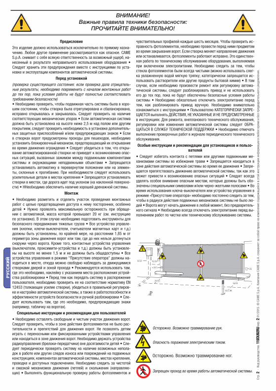
4 x 1,5
2 x 1 - TX
4 x 1
2 x 1,53 x 1,5
2 x 1
- RX
T R
G58
4 x 1,5
Стр.
22 -
Код
рук
овод
ства
: 119
DU92
RU11
9DU9
2RU
вер.
2 2 01
/201
5 ©
CAM
E S.
p.A.
Ком
пани
я CA
ME
S.p.
A. с
охра
няет
за
собо
й пр
аво
на и
змен
ение
сод
ерж
ащей
ся в
это
й ин
стру
кции
инф
орм
ации
в л
юбо
е вр
емя
и бе
з пр
едва
рите
льно
го у
ведо
мле
ния.
РУ
СС
КИ
Й
ПредисловиеЭто изделие должно использоваться исключительно по прямому назна-чению. Любое другое применение рассматривается как опасное. CAME S.p.A. снимает с себя всякую ответственность за возможный ущерб, на-несенный в результате неправильного использования оборудования • Следует хранить эти предупреждения вместе с инструкциями по уста-новке и эксплуатации компонентов автоматической системы.
Перед установкой(проверка существующего состояния: если проверка дала отрицатель-ные результаты, необходимо повременить с началом монтажных работ до тех пор, пока условия работы не будут полностью соответствовать требованиям безопасности)• Необходимо проверить, чтобы подвижная часть системы была в хоро-шем состоянии, чтобы створка была отрегулирована и сбалансирована, исправно открывалась и закрывалась. Следует проверить на наличие соответствующих механических упоров • Если автоматическая система должна быть установлена на высоте ниже 2,5 м над полом или другим покрытием, следует проверить необходимость в установке дополнитель-ных защитных приспособлений и/или предупреждающих знаков • Если в створках ворот предусмотрены проходы для пешеходов, необходимо установить блокировочный механизм, предотвращающий их открывание во время движения ограждения • Следует убедиться в том, что откры-вание автоматизированной створки не приведет к возникновению опас-ных ситуаций, вызванных зажимом между подвижными компонентами системы и окружающими неподвижными объектами • Запрещается устанавливать автоматику в перевернутом положении или на элемен-ты, склонные к прогибанию. При необходимости следует использовать усилительные детали в местах крепления • Запрещается устанавливать створки в местах, где дорога идет под уклоном (на наклонной поверхно-сти) • ННеобходимо обеспечить наличие хорошей дренажной системы.
Монтаж• Необходимо разметить и отделить участок проведения монтажных работ с целью предотвращения доступа к нему посторонних, особенно детей • Нужно проявлять максимальную осторожность при обраще-нии с автоматикой, масса которой превышает 20 кг (см. инструкцию по установке). В этом случае необходимо подготовить инструменты для безопасного передвижения тяжелых грузов • Все устройства управле-ния (кнопки, ключи-выключатели, считыватели магнитных карт и т.д.) должны быть установлены, по крайней мере, на расстоянии 1,85 м от периметра зоны движения ворот или там, где до них нельзя дотянуться снаружи через ворота. Кроме того, контактные устройства управления (выключатели, проксимити-устройства и т.д.) должны быть установле-ны на высоте не менее 1,5 м и не должны быть общедоступны • Все устройства управления в режиме "Присутствие оператора" должны на-ходиться в месте, откуда можно свободно наблюдать за движущимися створками дверей и зоной прохода • Рекомендуется использовать там, где это необходимо, наклейку с указанием места расположения устрой-ства разблокировки • Перед тем как передать систему в распоряжение пользователя, необходимо проверить ее на соответствие нормативу EN 12453 (толкающее усилие створки), убедиться в правильной регулиров-ке и настройке автоматической системы, а также в работоспособности и эффективности устройств безопасности и ручной разблокировки • Сле-дует использовать там, где это необходимо, предупреждающие знаки (например, табличку на воротах).
Специальные инструкции и рекомендации для пользователей• Необходимо оставлять свободным и чистым участок движения ворот. Следует проверить, чтобы в зоне действия фотоэлементов не было рас-тительности и препятствий для движения ворот. Не позволять детям играть с переносными или фиксированными устройствами управления или находиться в зоне движения ворот. Необходимо держать устройства радиоуправления (брелоки-передатчики) вне досягаемости детей • Сле-дует периодически проверять систему на наличие возможных непола-док в работе или других следов износа или повреждений на подвижных конструкциях, компонентах автоматической системы, местах крепления, проводке и доступных подключениях. Необходимо следить за чистотой и смазкой механизмов движения (петлей) и скольжения (направляю-щих) • Выполнять функциональную проверку работы фотоэлементов и
чувствительных профилей каждые шесть месяцев. Чтобы проверить ис-правность фотоэлементов, необходимо провести перед ними предметом во время закрывания ворот. Если створка меняет направление движения или останавливается, фотоэлементы работают исправно. Это единствен-ная работа по техническому обслуживанию оборудования, выполняемая при включенном электропитании. Необходимо следить за тем, чтобы стекла фотоэлементов были всегда чистыми (можно использовать слег-ка увлажненную водой мягкую тряпку; категорически запрещается ис-пользовать растворители или другие продукты бытовой химии) • В том случае, если необходимо произвести ремонт или регулировку автома-тической системы, следует разблокировать привод и не использовать его до тех пор, пока не будут обеспечены безопасные условия работы системы • Необходимо обязательно отключить электропитание перед тем, как разблокировать привод вручную. Необходимо внимательно ознакомиться с инструкциями • Пользователю КАТЕГОРИЧЕСКИ ЗАПРЕ-ЩАЕТСЯ выполнять ДЕЙСТВИЯ, НЕ УКАЗАННЫЕ И НЕ ПРЕДУСМОТРЕННЫЕ в инструкциях. Для ремонта, внепланового технического обслуживания, регулировки или изменения автоматической системы следует ОБРА-ЩАТЬСЯ В СЛУЖБУ ТЕХНИЧЕСКОЙ ПОДДЕРЖКИ • Необходимо отмечать выполнение проверочных работ в журнале периодического технического обслуживания. Особые инструкции и рекомендации для установщиков и пользо-
вателей• Следует избегать контакта с петлями или другими подвижными ме-ханизмами системы во избежание травм • Запрещается находиться в зоне действия автоматической системы во время ее движения • Запре-щается препятствовать движению автоматической системы, так как это может привести к возникновению опасных ситуаций • Следует всегда уделять особое внимание опасным местам, которые должны быть обо-значены специальными символами и/или черно-желтыми полосами • Во время использования ключа-выключателя или устройства управления в режиме «Присутствие оператора» необходимо постоянно следить за тем, чтобы в радиусе действия подвижных механизмов системы не было лю-дей • Ворота могут начать движение в любой момент, без предваритель-ного сигнала • Необходимо всегда отключать электропитание перед вы-полнением работ по чистке или техническому обслуживанию системы.
ВНИМАНИЕ!Важные правила техники безопасности:
ПРОЧИТАЙТЕ ВНИМАТЕЛЬНО!
Осторожно. Возможно травмирование рук.
Опасность поражения электрическим током.
Запрещен проход во время работы автоматической системы.
Осторожно. Возможно травмирование ног.

12
3
4
Стр.
33 -
Код
рук
овод
ства
: 119
DU92
RU11
9DU9
2RU
вер.
2 2 01
/201
5 ©
CAM
E S.
p.A.
Ком
пани
я CA
ME
S.p.
A. с
охра
няет
за
собо
й пр
аво
на и
змен
ение
сод
ерж
ащей
ся в
это
й ин
стру
кции
инф
орм
ации
в л
юбо
е вр
емя
и бе
з пр
едва
рите
льно
го у
ведо
мле
ния.
РУ
СС
КИ
Й
Электропитание блока управления: ~ 230 В 50/60 ГцЭлектропитание мотора: =24 В 50/60 ГцМакс. потребляемый ток: 10A Мощность: 120 ВтВремя открывания на 90°: регулируемое.
Передаточное отношение: 1/36Интенсивность использования: интенсивного использованияКласс защиты: IP44Масса: 10 кгДиапазон рабочих температур:
4.1 Привод
Это изделие разработано и изготовлено компанией CAME S.p.A. в полном соответствии с действующими нормами безопасности. Гарантия не распространяется на изделия, имеющие механические повреждения, а также следы самостоятельного ремонта.Корпус привода состоит из двух литых алюминиевых частей. Внутри расположены мотор, редуктор, концевые выключатели и ходовой винт.
4. Описание
2.1 Назначение
1. Условные обозначения
Этот символ обозначает раздел, требующий внимательного прочтения.
Этот символ обозначает раздел, связанный с вопросами безопасности.
Этот символ обозначает раздел, предназначенный для ознакомления конечного пользователя.
2. Назначение и ограничения по применению
Привод ATI 24V предназначен для автоматизации распашных ворот частных жилых домов и кондоминиумов, а также для интенсивного использования.
3. Нормы и стандарты
2.2 Ограничения по применениюЗапрещается использовать устройство не по назначению и устанавливать его методами, отличными от содержащихся в настоящей инструкции.
4.2 Технические характеристики
CAME S.p.A. применяет комплексную систему управления качеством, сертифицированную в соответствии с международным стандартом ISO 9001, и систему экологического менеджмента, сертифицированную в соответствии с международным стандартом ISO 14001.Изделие соответствует требованиям следующих стандартов: смотрите декларацию о соответствии.
4.3 Основные компоненты
1) Привод2) Передний кронштейн3) Подвижный хвостовик4) Задний кронштейн
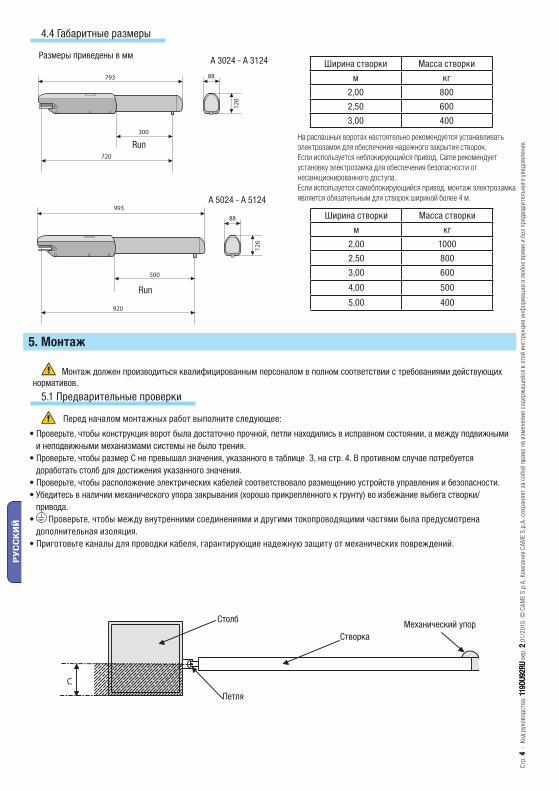
A 3024 - A 3124
A 5024 - A 5124
Стр.
44 -
Код
рук
овод
ства
: 119
DU92
RU11
9DU9
2RU
вер.
2 2 01
/201
5 ©
CAM
E S.
p.A.
Ком
пани
я CA
ME
S.p.
A. с
охра
няет
за
собо
й пр
аво
на и
змен
ение
сод
ерж
ащей
ся в
это
й ин
стру
кции
инф
орм
ации
в л
юбо
е вр
емя
и бе
з пр
едва
рите
льно
го у
ведо
мле
ния.
РУ
СС
КИ
Й
4.4 Габаритные размеры
Размеры приведены в ммШирина створки Масса створки
м кг
2,00 800
2,50 600
3,00 400
Ширина створки Масса створки
м кг
2,00 1000
2,50 800
3,00 600
4,00 500
5,00 400
Перед началом монтажных работ выполните следующее:
• Проверьте, чтобы конструкция ворот была достаточно прочной, петли находились в исправном состоянии, а между подвижными и неподвижными механизмами системы не было трения.
• Проверьте, чтобы размер C не превышал значения, указанного в таблице 3, на стр. 4. В противном случае потребуется доработать столб для достижения указанного значения.
• Проверьте, чтобы расположение электрических кабелей соответствовало размещению устройств управления и безопасности.• Убедитесь в наличии механического упора закрывания (хорошо прикрепленного к грунту) во избежание выбега створки/
привода.• Проверьте, чтобы между внутренними соединениями и другими токопроводящими частями была предусмотрена
дополнительная изоляция.• Приготовьте каналы для проводки кабеля, гарантирующие надежную защиту от механических повреждений.
Монтаж должен производиться квалифицированным персоналом в полном соответствии с требованиями действующих нормативов.
5. Монтаж
5.1 Предварительные проверки
Run
Run
Столб
СтворкаМеханический упор
Петля
На распашных воротах настоятельно рекомендуется устанавливать электрозамок для обеспечения надежного закрытия створок.Если используется неблокирующийся привод, Came рекомендует установку электрозамка для обеспечения безопасности от несанкционированного доступа.Если используется самоблокирующийся привод, монтаж электрозамка является обязательным для створок шириной более 4 м.

2 x 1 - TX
4 x 1
2 x 1,53 x 1,5
2 x 1
3 x 1230 V
4 x 1 - RX
T R
G58
* *1
1
2 34
4 5
44
67
8
*
Стр.
55 -
Код
рук
овод
ства
: 119
DU92
RU11
9DU9
2RU
вер.
2 2 01
/201
5 ©
CAM
E S.
p.A.
Ком
пани
я CA
ME
S.p.
A. с
охра
няет
за
собо
й пр
аво
на и
змен
ение
сод
ерж
ащей
ся в
это
й ин
стру
кции
инф
орм
ации
в л
юбо
е вр
емя
и бе
з пр
едва
рите
льно
го у
ведо
мле
ния.
РУ
СС
КИ
Й
5.2 Инструменты и материалы
Перед началом монтажных работ следует убедиться в наличии всех необходимых инструментов и материалов, которые позволят произвести установку оборудования в полном соответствии с действующими нормами безопасности. Ниже представлен минимальный набор инструментов для монтажника.
Важное примечание: Важное примечание: сечение кабелей, длина которых отличается от приведенной в таблице, должно рассматриваться с учетом фактического потребления тока подключенными устройствами в соответствии с указаниями стандарта CEI EN 60204-1.Для последовательных подключений, предусматривающих большую нагрузку на тот же участок цепи, значения в таблице должны быть пересмотрены с учетом реальных показателей потребления и расстояний.
5.3 Тип и сечение кабелей
Подключения Тип кабеля Длина кабеля1 < 10 м
Длина кабеля10 < 20 м
Длина кабеля20 < 30 м
Электропитание блока управления ~230 В
FROR CEI 20-22 CEI EN
50267-2-1
3G x 1,5 мм2 3G x 2,5 мм2 3G x 4 мм2
Сигнальная лампа 24 В 2 x 0,5 мм2 2 x 1 мм2 2 x 1,5 мм2
Фотоэлементы (передатчики) 2 x 0,5 мм2 2 x 0,5 мм2 2 x 0,5 мм2
Фотоэлементы (приемники) 4 x 0,5 мм2 4 x 0,5 мм2 4 x 0,5 мм2
Электропитание аксессуаров 24 В 2 x 0,5 мм2 2 x 0,5 мм2 2 x 1 мм2
Кнопки управления 2 x 0,5 мм2 2 x 0,5 мм2 2 x 0,5 мм2
Концевой выключатель 3 x 0,5 мм2 3 x 1 мм2 3 x 1,5 мм2
Подключение энкодера 2402C 22AWG макс. 30 м
Антенный кабель RG58 макс. 50 м
1) Привод2) Блок управления3) Плата радиоприемника4) Фотоэлементы
5.4 Вариант типовой установки
Кабель подключения концевых выключателей:5 x 1 мм2
Кабель электропитания привода:2 x 1,5 мм2 до 20 м;2 x 2,5 мм2 до 30 м;
безопасности 5) Ключ-выключатель6) Антенна7) Сигнальная лампа8) Брелок-передатчик
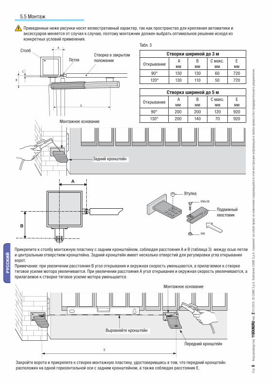
Стр.
66 -
Код
рук
овод
ства
: 119
DU92
RU11
9DU9
2RU
вер.
2 2 01
/201
5 ©
CAM
E S.
p.A.
Ком
пани
я CA
ME
S.p.
A. с
охра
няет
за
собо
й пр
аво
на и
змен
ение
сод
ерж
ащей
ся в
это
й ин
стру
кции
инф
орм
ации
в л
юбо
е вр
емя
и бе
з пр
едва
рите
льно
го у
ведо
мле
ния.
РУ
СС
КИ
Й
Приведенные ниже рисунки носят иллюстративный характер, так как пространство для крепления автоматики и аксессуаров меняется от случая к случаю, поэтому монтажник должен выбрать оптимальное решение исходя из конкретных условий применения.
5.5 Монтаж
Прикрепите к столбу монтажную пластину с задним кронштейном, соблюдая расстояния A и B (таблица 3) между осью петли и центральным отверстием кронштейна. Задний кронштейн имеет несколько отверстий для регулировки угла открывания ворот.Примечание: при увеличении расстояния В угол открывания и окружная скорость уменьшаются, а прилагаемое к створке тяговое усилие мотора увеличивается. При увеличении расстояния А угол открывания и окружная скорость увеличиваются, а прилагаемое к створке тяговое усилие мотора уменьшается.
Закройте ворота и прикрепите к створке монтажную пластину, удостоверившись в том, что передний кронштейн расположен на одной горизонтальной оси с задним кронштейном, а также соблюдая расстояние Е.
Столб
ПетляСтворка в закрытом положении
Табл. 3
Монтажное основание
Задний кронштейн
Втулка
Подвижный хвостовик
Выровняйте кронштейн
Монтажное основание
Передний кронштейн
Створки шириной до 3 м
Открывание A мм
B мм
C макс. мм
Eмм
90° 130 130 60 720
120° 130 110 50 720
Створка шириной до 5 м
Открывание A мм
B мм
C макс. мм
Eмм
90° 200 200 120 920
130° 200 140 70 920

M8x10
M8x50
N M F FA RC R RA
Стр.
77 -
Код
рук
овод
ства
: 119
DU92
RU11
9DU9
2RU
вер.
2 2 01
/201
5 ©
CAM
E S.
p.A.
Ком
пани
я CA
ME
S.p.
A. с
охра
няет
за
собо
й пр
аво
на и
змен
ение
сод
ерж
ащей
ся в
это
й ин
стру
кции
инф
орм
ации
в л
юбо
е вр
емя
и бе
з пр
едва
рите
льно
го у
ведо
мле
ния.
РУ
СС
КИ
Й
Колодка подключения привода
Колодка подключения блока управления
Привод 1 N1 M1 C Fa1 Rc1 C Ra1Привод 2 N2 M2 C Fa2 Rc2 C Ra2 ZL 19N
N - MПодключение привода
F - FaКонцевой микровыключатель открывания
R - RcМикровыключатель с функцией замедления при закрывании
R - RaМикровыключатель с функцией замедления при открывании
Отверните два самореза и снимите крышку.
Снимите крышку винта, отвернув два самореза.
Примечание: рекомендуется смазать (жирной смазкой) ходовой винт и втулку до установки привода.
Установите привод на передний и задний кронштейны.
Гайка M8 самоблокирующаяся
Ходовой винт
5.6. Электрические подключения к блоку управления ZL 19N
Крышка
Кожух ходового винта

100
mm
Стр.
88 -
Код
рук
овод
ства
: 119
DU92
RU11
9DU9
2RU
вер.
2 2 01
/201
5 ©
CAM
E S.
p.A.
Ком
пани
я CA
ME
S.p.
A. с
охра
няет
за
собо
й пр
аво
на и
змен
ение
сод
ерж
ащей
ся в
это
й ин
стру
кции
инф
орм
ации
в л
юбо
е вр
емя
и бе
з пр
едва
рите
льно
го у
ведо
мле
ния.
РУ
СС
КИ
Й
ОТКРЫВАНИЕ
Разблокируйте привод и установите створку в максимально открытое положение, отверните крепежные винты микровыключателя открывания.
Перемещайте микровыключатели по направляющей до тех пор, пока не произойдет его контакт с кареткой.Перемещайте микровыключатель по направляющей до тех пор, пока не произойдет его контакт с кареткой.
Закрепите микровыключатели, используя соответствующие винты.
ЗАКРЫВАНИЕ:
установите створку на расстоянии в приблизительно
100 мм от механического упора закрывания (дет. B).Отверните крепежные винты микровыключателя замедления при закрывании.
Перемещайте микровыключатель по направляющей до тех пор, пока не произойдет его контакт с кареткой.
Закрепите микровыключатель, используя соответствующие винты.
5.7 Регулировка микровыключателей замедления при открывании и закрывании
Механический упор
Микровыключатель замедления и остановки при открывании
Фиксатор кабеля
Направляющая микровыключателей
Микровыключатель замедления при закрывании
Ходовой винт
Каретка микровыключателей
Бронзовая втулкаСаморезы
Бронзовая втулка

CAME
180
Стр.
99 -
Код
рук
овод
ства
: 119
DU92
RU11
9DU9
2RU
вер.
2 2 01
/201
5 ©
CAM
E S.
p.A.
Ком
пани
я CA
ME
S.p.
A. с
охра
няет
за
собо
й пр
аво
на и
змен
ение
сод
ерж
ащей
ся в
это
й ин
стру
кции
инф
орм
ации
в л
юбо
е вр
емя
и бе
з пр
едва
рите
льно
го у
ведо
мле
ния.
РУ
СС
КИ
Й
Разблокируйте привод и установите створку в максимально открытое положение, отверните саморезы микровыключателей.
Перемещайте микровыключатель по направляющей до тех пор, пока не произойдет его контакт с кареткой.
Закрепите микровыключатель, используя соответствующие винты.
ДЛЯ РАЗБЛОКИРОВКИ:
Процедура разблокировки выполняется при выключенном электропитании мотора:
1) приподнимите дверцу;
2) вставьте и поверните ключ;
3) толкните или потяните створку вручную.
Чтобы заново заблокировать створку, достаточно повторно вставить и повернуть ключ.
5.8 Регулировка микровыключателя остановки при открывании
Направляющая микровыключателей
Каретка микровыключателей
Ходовой винт
Бронзовая втулка
Винт крепления
Микровыключатель
5.9 Разблокировка с помощью ключа
Дверца
Ключ

A
B
E
N1 M1 F FA1 RC1 R1 RA1
N2 M2 F FA1 RC2 R2 RA2
N M F FA RC R RA
A 3024 - A 3124 A 5024 - A 5124
A 130 mm 200 mm
B 130 mm 200 mm
E 720 mm 920 mm
Стр.
1010
- К
од р
уков
одст
ва: 1
19DU
92RU
119D
U92R
U ве
р. 2
2 01
/201
5 ©
CAM
E S.
p.A.
Ком
пани
я CA
ME
S.p.
A. с
охра
няет
за
собо
й пр
аво
на и
змен
ение
сод
ерж
ащей
ся в
это
й ин
стру
кции
инф
орм
ации
в л
юбо
е вр
емя
и бе
з пр
едва
рите
льно
го у
ведо
мле
ния.
РУ
СС
КИ
Й
5.10 Монтаж с открыванием наружу
ТАБЛ. A
Наружная сторона объекта
Внутренняя сторона объекта
Дополнительная пластина
- Определите расстояния A и B (табл. 4).
- Соедините задний кронштейн с дополнительной пластиной и прикрепите конструкцию к столбу.
- Откройте ворота (на макс. 90°), определите расстояние E (табл. 4) и прикрепите передний кронштейн к створке.
- Выполните электрические подключения, как показано на рисунке.
- Установите и отрегулируйте положение микровыключателя открывания.
Колодка подключения привода
Колодка подключения блока управления
Привод 1
Привод 2
7. Техническое обслуживание
7.1 Периодическое техническое обслуживание, осуществляемое пользователем
☞ Перед выполнением работ по техническому обслуживанию отключите электропитание во избежание возникновения опасных ситуаций, вызванных непроизвольным движением ворот.При появлении постороннего шума или вибрации смазывайте шарнирные соединения густой смазкой, как показано на рисунке.

Стр.
1111
- К
од р
уков
одст
ва: 1
19DU
92RU
119D
U92R
U ве
р. 2
2 01
/201
5 ©
CAM
E S.
p.A.
Ком
пани
я CA
ME
S.p.
A. с
охра
няет
за
собо
й пр
аво
на и
змен
ение
сод
ерж
ащей
ся в
это
й ин
стру
кции
инф
орм
ации
в л
юбо
е вр
емя
и бе
з пр
едва
рите
льно
го у
ведо
мле
ния.
РУ
СС
КИ
Й
НЕИСПРАВНОСТЬ ВОЗМОЖНАЯ ПРИЧИНА СПОСОБ УСТРАНЕНИЯ
Створка ворот не двигается.
• Нет напряжения питания.• Разблокирован привод.• Разрядились батарейки брелока-передатчика.• Сломан брелок-передатчик.• Кнопка "Стоп" заедает или неисправна.• Кнопки управления ворот или ключ-выключатель заедают или неисправны.
• Включите электропитание.• Обратитесь к установщику.• Замените батарейки.• Обратитесь к установщику.• Обратитесь к установщику.• Обратитесь к установщику.
Ворота только открываются.
• Срабатывают фотоэлементы. • Проверьте чистоту и исправность фотоэлементов.• Обратитесь к установщику.
Не работает сигнальная лампа.
• Лампа перегорела. • Обратитесь к установщику.
7.2 Возможные неисправности и способы их устранения
8. Техническое обслуживание
Дата Заметки Подпись
Бланк регистрации работ по периодическому обслуживанию, заполняемый пользователем (каждые 6 месяцев)
8.1 Внеплановое техническое обслуживание
Место печати Компания
Дата проведения работ
Подпись установщика
Подпись заказчика
Выполненные работы _____________________________________________________________________________________________________________________________________________________________________________________________________________________________________________________________________________________
Эта таблица необходима для записи внеплановых работ по обслуживанию и ремонту оборудования, выполненных специализированными предприятиями.
Важное примечание: ремонт оборудования должен осуществляться квалифицированными специалистами.
Бланк регистрации работ по внеплановому техническому обслуживанию
Место печати Компания
Дата проведения работ
Подпись установщика
Подпись заказчика
Выполненные работы _____________________________________________________________________________________________________________________________________________________________________________________________________________________________________________________________________________________
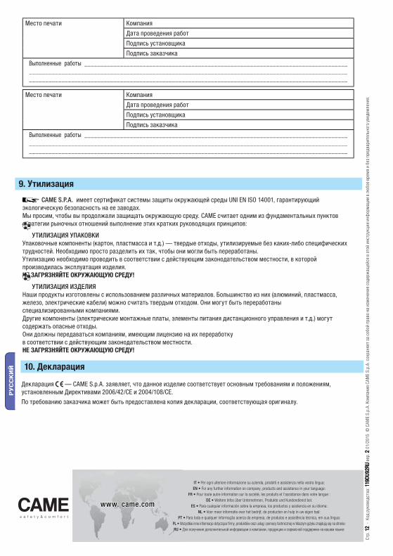
www. came.comwww. came.com
IT • Per ogni ulteriore informazione su azienda, prodotti e assistenza nella vostra lingua:EN • For any further information on company, products and assistance in your language:
FR • Pour toute autre information sur la société, les produits et l’assistance dans votre langue :DE • Weitere Infos über Unternehmen, Produkte und Kundendienst bei:
ES • Para cualquier información sobre la empresa, los productos y asistencia en su idioma:NL • Voor meer informatie over het bedrijf, de producten en hulp in uw eigen taal:
PT • Para toda e qualquer informação acerca da empresa, de produtos e assistência técnica, em sua língua:PL • Wszystkie inne informacje dotyczące fi rmy, produktów oraz usług i pomocy technicznej w Waszym języku znajdują się na stronie:RU • Для получения дополнительной информации о компании, продукции и сервисной поддержке на вашем языке:
Стр.
1212
- К
од р
уков
одст
ва: 1
19DU
92RU
119D
U92R
U ве
р. 2
2 01
/201
5 ©
CAM
E S.
p.A.
Ком
пани
я CA
ME
S.p.
A. с
охра
няет
за
собо
й пр
аво
на и
змен
ение
сод
ерж
ащей
ся в
это
й ин
стру
кции
инф
орм
ации
в л
юбо
е вр
емя
и бе
з пр
едва
рите
льно
го у
ведо
мле
ния.
РУ
СС
КИ
Й
CAME S.P.A. имеет сертификат системы защиты окружающей среды UNI EN ISO 14001, гарантирующий экологическую безопасность на ее заводах.Мы просим, чтобы вы продолжали защищать окружающую среду. САМЕ считает одним из фундаментальных пунктов стратегии рыночных отношений выполнение этих кратких руководящих принципов:
УТИЛИЗАЦИЯ УПАКОВКИУпаковочные компоненты (картон, пластмасса и т.д.) — твердые отходы, утилизируемые без каких-либо специфических трудностей. Необходимо просто разделить их так, чтобы они могли быть переработаны.Утилизацию необходимо проводить в соответствии с действующим законодательством местности, в которой производилась эксплуатация изделия.НЕ ЗАГРЯЗНЯЙТЕ ОКРУЖАЮЩУЮ СРЕДУ!
УТИЛИЗАЦИЯ ИЗДЕЛИЯНаши продукты изготовлены с использованием различных материалов. Большинство из них (алюминий, пластмасса, железо, электрические кабели) можно считать твердым отходом. Они могут быть переработаныспециализированными компаниями. Другие компоненты (электрические монтажные платы, элементы питания дистанционного управления и т.д.) могут содержать опасные отходы. Они должны передаваться компаниям, имеющим лицензию на их переработкув соответствии с действующим законодательством местности.НЕ ЗАГРЯЗНЯЙТЕ ОКРУЖАЮЩУЮ СРЕДУ!
9. Утилизация
Место печати Компания
Дата проведения работ
Подпись установщика
Подпись заказчика
Выполненные работы _____________________________________________________________________________________________________________________________________________________________________________________________________________________________________________________________________________________
10. Декларация
Декларация — CAME S.p.A. заявляет, что данное изделие соответствует основным требованиям и положениям, установленным Директивами 2006/42/CE и 2004/108/CE.По требованию заказчика может быть предоставлена копия декларации, соответствующая оригиналу.