624 BLD - faac.fr techniques/13 PLATINE... · e/o rappresentare fonte di pericolo. 6) ... F = F 0A...
116
624 BLD 624 BLD
Transcript of 624 BLD - faac.fr techniques/13 PLATINE... · e/o rappresentare fonte di pericolo. 6) ... F = F 0A...

624 BLD624 BLD

�
INDICE1....AVVERTENZE.................................................................................................................................................3
2....CARATTERISTICHE.TECNICHE.........................................................................................................................3
3....LAYOUT.E.COMPONENTI.624BLD..................................................................................................................3
3.1.Descrizione.componenti........................................................................................................................3
4....COLLEGAMENTI.ELETTRICI............................................................................................................................4
4.1...Morsettiera.J1.-.Accessori.(Fig..2).......................................................................................................4
4.2...Collegamento.fotocellule.a.rele’.e.dispositivi.di.sicurezza.con.contatto.“N.C.”................................5
4.3...Collegamento.fotocellule.BUS.............................................................................................................5
4.4...Morsettiera.J2.-.Motore,.lampeggiatore.e.ventola.(Fig..2)................................................................6
4.5...Connettore.J8.-.Condensatore.motore.(Fig..2)...................................................................................6
4.6...Morsettiera.J9.-.Alimentazione.(Fig..2)................................................................................................6
4.7...Connettori.J3,.J5.-.Innesto.rapido.finecorsa.apertura.e.chiusura.(Fig..2).........................................6
4.8...Connettore.J6.-.Sensore.sfondamento.sbarra.(Fig..2)................................................................................6
4.9...Selettore.frequenza.DS1.(Fig..1)..........................................................................................................6
4.10.Connettore.J4.-.Innesto.Minidec,.Decoder.e.RP....................................................................................6
5....PROGRAMMAZIONE.....................................................................................................................................6
5.1...PROGRAMMAZIONE.1°.LIVELLO............................................................................................................6
5.2...Modifica.dei.pre-setting......................................................................................................................8
5.3...Impostazione.e.controllo.sistema.BUS................................................................................................8
5.4...PROGRAMMAZIONE.2°.LIVELLO............................................................................................................9
5.5...Impostazione.Loop.Detector.integrato...............................................................................................10
6....MESSA.IN.FUNZIONE.....................................................................................................................................11
6.1...Verifica.dei.LED.a.scheda...................................................................................................................11
6.2...Verifica.stato.del.BUS...........................................................................................................................11
7....PROVA.DELL’AUTOMAZIONE..........................................................................................................................11
8....CONFIGURAZIONI.MASTER-SLAVE.................................................................................................................12
9....PROGRAMMAZIONE.3°.LIVELLO....................................................................................................................13
9.1...Programmazione.della.logica.di.pre-setting......................................................................................15
10...VALORI.DEI.PRE-SETTING.............................................................................................................................15
11...NOTE..........................................................................................................................................................16
12...COLLEGAMENTO.INTERBLOCCO.................................................................................................................16
13...TABELLE.LOGICHE.DI.FUNZIONAMENTO......................................................................................................17
ITA
LIA
NO

�
DICHIARAZIONE CE DI CONFORMITÁ
Fabbricante: FAAC S.p.A.
Indirizzo: Via Calari, �0 - 40069 Zola Predosa BOLOGNA - ITALIA
Dichiara che: L’apparecchiatura elettronica 6�4BLD
• ·è conforme ai requisiti essenziali di sicurezza delle seguenti direttive CEE
�006/95/CE Direttiva Bassa Tensione �004/�08/CE Direttiva Compatibilità Elettromagnetica
Nota aggiuntiva: Questo prodotto è stato sottoposto a test in una configurazione tipica omogenea (tutti prodotti di costruzione FAAC S.p.A.).
Bologna, 0� Gennaio �0�0
L’Amministratore Delegato A. Marcellan
1) ATTENZIONE!Èimportanteperlasicurezzadellepersoneseguireatten-tamentetuttal’istruzione.Unaerratainstallazioneounerratousodelprodottopuòportareagravidanniallepersone.
2) Leggere attentamente le istruzioni prima di iniziare l’installazione delprodotto.
3) Imaterialidell’imballaggio(plastica,polistirolo,ecc.)nondevonoesserelasciatiallaportatadeibambiniinquantopotenzialifontidipericolo.
4) Conservareleistruzioniperriferimentifuturi.
5) Questo prodotto è stato progettato e costruito esclusivamente perl’utilizzoindicatoinquestadocumentazione.Qualsiasialtroutilizzononespressamenteindicatopotrebbepregiudicarel’integritàdelprodottoe/orappresentarefontedipericolo.
6) FAAC declina qualsiasi responsabilità derivata dall’uso improprio odiversodaquellopercuil’automatismoèdestinato.
7) Noninstallarel’apparecchioinatmosferaesplosiva:lapresenzadigasofumiinfiammabilicostituisceungravepericoloperlasicurezza.
8) GlielementicostruttivimeccanicidevonoessereinaccordoconquantostabilitodalleNormeEN12604eEN12605.
PeriPaesiextra-CEE,oltreairiferimentinormativinazionali,perottenereunlivellodisicurezzaadeguato,devonoessereseguiteleNormesoprariportate.
9) FAACnonèresponsabiledell’inosservanzadellaBuonaTecnicanellacostruzionedellechiusuredamotorizzare,nonchédelledeformazionichedovesserointervenirenell’utilizzo.
10) L’installazionedeveessereeffettuatanell’osservanzadelleNormeEN12453eEN12445.
PeriPaesiextra-CEE,oltreairiferimentinormativinazionali,perottenereunlivellodisicurezzaadeguato,devonoessereseguiteleNormesoprariportate.
11) Primadieffettuarequalsiasiinterventosull’impianto,toglierel’alimen-tazioneelettrica.
12) Prevederesullaretedialimentazionedell’automazioneuninterruttoreonnipolarecondistanzad’aperturadeicontattiugualeosuperiorea3mm.Èconsigliabilel’usodiunmagnetotermicoda6Aconinterruzioneonnipolare.
13) Verificarecheamontedell’impiantovisiauninterruttoredifferenzialeconsogliada0,03A.
14) Verificarechel’impiantoditerrasiarealizzatoaregolad’arteecolle-garvilepartimetallichedellachiusura.
15) L’automazionedisponediunasicurezzaintrinsecaantischiacciamentocostituitadauncontrollodicoppia.E’comunquenecessarioverificarnelasogliadiinterventosecondoquantoprevistodalleNormeindicatealpunto10.
16) Idispositividisicurezza(normaEN12978)permettonodiproteggereeventualiareedipericolodaRischimeccanicidimovimento,comeadEs.schiacciamento,convogliamento,cesoiamento.
17) Perogniimpiantoèconsigliatol’utilizzodialmenounasegnalazioneluminosa(es:FAACLIGHT)nonchédiuncartellodisegnalazionefissatoadeguatamente sulla strutturadell’infisso,oltreaidispositivicitatialpunto“16”.
18) FAACdeclinaogniresponsabilitàaifinidellasicurezzaedelbuonfun-zionamentodell’automazione,incasovenganoutilizzaticomponentidell’impiantonondiproduzioneFAAC.
19) PerlamanutenzioneutilizzareesclusivamentepartioriginaliFAAC.
20) Noneseguirealcunamodificasuicomponentifacentipartedelsistemad’automazione.
21) L’installatoredeveforniretutteleinformazionirelativealfunzionamentomanualedelsistemaincasodiemergenzaeconsegnareall’Utenteutilizzatoredell’impiantoillibrettod’avvertenzeallegatoalprodotto.
22) Nonpermettereaibambiniopersonedisostarenellevicinanzedelprodottoduranteilfunzionamento.
23) Tenerefuoridallaportatadeibambiniradiocomandioqualsiasialtrodatorediimpulso,perevitarechel’automazionepossaessereazionatainvolontariamente.
24) Iltransitodeveavveniresoloadautomazioneferma.
25) L’Utenteutilizzatoredeveastenersidaqualsiasitentativodiriparazioneod’interventodirettoerivolgersisoloapersonalequalificato.
26) Manutenzione:effettuarealmenosemestralmentelaverificafunzionaledell’impianto,conparticolareattenzioneall’efficienzadeidispositividisicurezza(compresa,oveprevisto,laforzadispintadell’operatore)edisblocco.
27) Tuttoquellochenonèprevistoespressamenteinquesteistruzioninonèpermesso.
AVVERTENZEPERL’INSTALLATORE
OBBLIGHIGENERALIPERLASICUREZZA
ITA
LIA
NO

�
.1.. AVVERTENZE
Attenzione: Prima di effettuare qualsiasi tipo di intervento sull’apparecchiatura elettronica (collegamenti, manutenzione) togliere sempre l’alimentazione elettrica.
- Prevedere a monte dell’impianto un interruttore magnetotermico differenziale con adeguata soglia di intervento.- Collegare il cavo di terra all’apposito morsetto previsto sul connettore J9 dell’apparecchiatura (vedi fig.2).- Separare sempre i cavi di alimentazione da quelli di comando e di sicurezza (pulsante, ricevente, fotocellule, ecc.). Per
evitare qualsiasi disturbo elettrico utilizzare guaine separate o cavo schermato (con schermo collegato a massa).
APPARECCHIATURA ELETTRONICA 624 BLD
.3.. LAYOUT.E.COMPONENTI.624BLD
Tensione dialimentazione *
��0 V~ (+6% -�0%) - 50/60 Hzoppure
��5 V~ (+6% -�0%) - 50/60 Hz
Potenza assorbita 7 W
Carico max Motore �000 W
Alimentazioneaccessori �4 Vdc
Corrente maxaccessori 500 mA
Temperaturaambiente da -�0°C a +55°C
Fusibili diprotezione *
F� = F �0A - �50V F� = T 0,8A - �50Voppure
F� = F �0A - ��0V F� = T 0,8A - ��0V
Tempo di lavoro Programmabile (da 0 a 4 min)
Tempo di pausa Programmabile (da 0 a 4 min)
Forza motore Programmabile su 50 livelli
Programmazione � livelli di programmazione per una maggiore flessibilità d’impiego
Connettore rapidoInnesto scheda a 5pin Minidec,
Decoder, Ricevente RP/RP�
Usciteprogrammabili
4 uscite programmabiliin �8 differenti funzioni
Caratteristiche
Gestione rallentamenti, Dispaly multi-funzione, tecnologia BUS e
RILEVATORE DI MASSE METALLICHEINTEGRATO
* La tensione di alimentazione ed i fusibili sono in relazione alla versione acquistata
.2.. CARATTERISTICHE.TECNICHE
3.1.DESCRIZIONE.COMPONENTI
DL DISPLAY DI SEGNALAZIONE E PROGRAMMAZIONE
LED LEDS DI CONTROLLO STATO INGRESSI
J1 MORSETTIERA BASSA TENSIONE
J2 MORSETTIERA COLLEGAMENTO MOTORE, LAMPEGGIATORE E VENTOLA
J3 CONNETTORE FINECORSA DI APERTURA
J4 CONNETTORE DECODER / MINIDEC / RICEVENTE RP
J5 CONNETTORE FINECORSA DI CHIUSURA
J6 CONNETTORE SENSORE SFONDAMENTO ASTA
J8 CONNETTORE CONDENSATORE DI SPUNTO MOTORE
J9 MORSETTIERA ALIMENTAZIONE ��0 VAC
DS1 SELETTORE FREQUENZE LOOP � e LOOP �
F1 FUSIBILE MOTORI E PRIMARIO TRASFORMATORE (F 5A)
F2 FUSIBILE BASSA TENSIONE E ACCESSORI (T 800mA)
F PULSANTE PROGRAMMAZIONE “F”
+ PULSANTE PROGRAMMAZIONE “+”
- PULSANTE PROGRAMMAZIONE “-”
TF1 TRASFORMATORE
Fig. 1
ITA
LIA
NO
4
.4.. COLLEGAMENTI.ELETTRICI
Per il collegamento delle fotocellule
e dei dispositivi di sicurezza, riferirsi al
paragrafo 4.2.
BLU
CONDENSATORESPUNTO MOTORE
VENTOLA
MOTORE
SFONDAMENTOSBARRA
Fig. 2
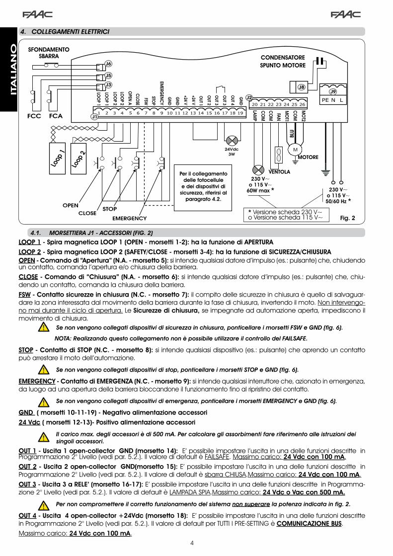
LOOP 1 - Spira magnetica LOOP 1 (OPEN - morsetti 1-2): ha la funzione di APERTURALOOP 2 - Spira magnetica LOOP 2 (SAFETY/CLOSE - morsetti 3-4): ha la funzione di SICUREZZA/CHIUSURAOPEN - Comando di “Apertura” (N.A. - morsetto 5): si intende qualsiasi datore d’impulso (es.: pulsante) che, chiudendo un contatto, comanda l’apertura e/o chiusura della barriera.CLOSE - Comando di “Chiusura” (N.A. - morsetto 6): si intende qualsiasi datore d’impulso (es.: pulsante) che, chiu-dendo un contatto, comanda la chiusura della barriera.FSW - Contatto sicurezze in chiusura (N.C. - morsetto 7): il compito delle sicurezze in chiusura è quello di salvaguar-dare la zona interessata dal movimento della barriera durante la fase di chiusura, invertendo il moto. Non intervengo-no mai durante il ciclo di apertura. Le Sicurezze di chiusura, se impegnate ad automazione aperta, impediscono il movimento di chiusura.
Se.non.vengono.collegati.dispositivi.di.sicurezza.in.chiusura,.ponticellare.i.morsetti.FSW.e.GND.(fig..6).
..........NOTA:.Realizzando.questo.collegamento.non.è.possibile.utilizzare.il.controllo.del.FAILSAFE.
STOP - Contatto di STOP (N.C. - morsetto 8): si intende qualsiasi dispositivo (es.: pulsante) che aprendo un contatto può arrestare il moto dell’automazione.
Se.non.vengono.collegati.dispositivi.di.stop,.ponticellare.i.morsetti.STOP.e.GND.(fig..6).
EMERGENCY - Contatto di EMERGENZA (N.C. - morsetto 9): si intende qualsiasi interruttore che, azionato in emergenza, da luogo ad una apertura della barriera bloccandone il funzionamento fino al ripristino del contatto.
Se.non.vengono.collegati.dispositivi.di.emergenza,.ponticellare.i.morsetti.EMERGENCY.e.GND.(fig..6).
GND ( morsetti 10-11-19) - Negativo alimentazione accessori24 Vdc ( morsetti 12-13)- Positivo alimentazione accessori
. Il.carico.max..degli.accessori.è.di.500.mA..Per.calcolare.gli.assorbimenti.fare.riferimento.alle.istruzioni.dei.singoli.accessori.
OUT 1 - Uscita 1 open-collector GND (morsetto 14): E’ possibile impostare l’uscita in una delle funzioni descritte in Programmazione �° Livello (vedi par. 5.�.). Il valore di default è FAILSAFE. Massimo carico: 24 Vdc con 100 mA.OUT 2 - Uscita 2 open-collector GND(morsetto 15): E’ possibile impostare l’uscita in una delle funzioni descritte in Programmazione �° Livello (vedi par. 5.�.). Il valore di default è sbarra CHIUSA.Massimo carico: 24 Vdc con 100 mA.OUT 3 - Uscita 3 a RELE’ (morsetto 16-17): E’ possibile impostare l’uscita in una delle funzioni descritte in Programma-zione �° Livello (vedi par. 5.�.). Il valore di default è LAMPADA SPIA.Massimo carico: 24 Vdc o Vac con 500 mA.
. Per.non.compromettere.il.corretto.funzionamento.del.sistema.non.superare.la.potenza.indicata.in.fig..2.
OUT 4 - Uscita 4 open-collector +24Vdc (morsetto 18): E’ possibile impostare l’uscita in una delle funzioni descritte in Programmazione �° Livello (vedi par. 5.�.). Il valore di default per TUTTI I PRE-SETTING è COMUNICAZIONE BUS.Massimo carico: 24 Vdc con 100 mA.
4.1.. MORSETTIERA.J1.-.ACCESSORI.(FIG..2)
230 V~o 115 V~
60W max * 230 V~o 115 V~50/60 Hz *
* Versione scheda ��0 V~o Versione scheda ��5 V~
ITA
LIA
NO
5
191816 17151412 1310 118 96 74 52 31
OPEN
A
STOP
LOO
P1
LOO
P2
LOO
P2
LOO
P1
CLO
SE
FSW
EMERG
ENC
Y
OUT1
OUT2
OUT4
OUT3
GN
D
GN
D
GN
D
+24V
+24V
OUT3
J1
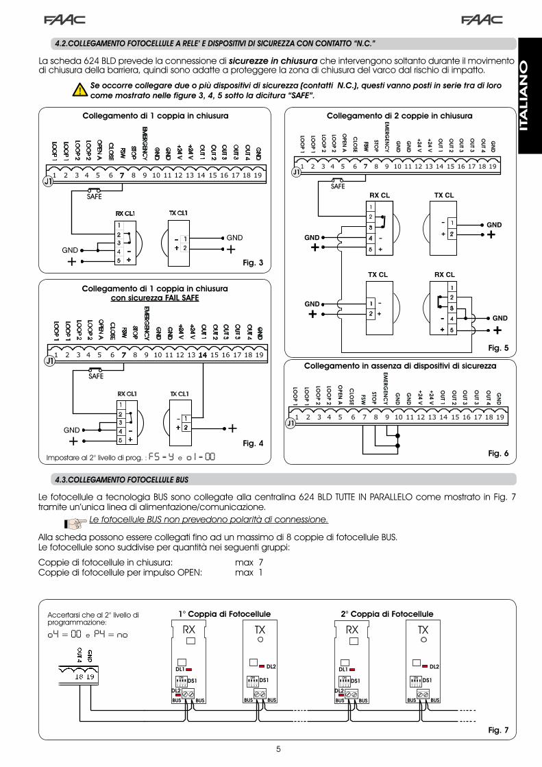
La scheda 6�4 BLD prevede la connessione di sicurezze.in.chiusura che intervengono soltanto durante il movimento di chiusura della barriera, quindi sono adatte a proteggere la zona di chiusura del varco dal rischio di impatto.
. .Se.occorre.collegare.due.o.più.dispositivi.di.sicurezza.(contatti..N.C.),.questi.vanno.posti.in.serie.tra.di.loro.come.mostrato.nelle.figure.3,.4,.5.sotto.la.dicitura.“SAFE”.
4.2.COLLEGAMENTO.FOTOCELLULE.A.RELE’.E.DISPOSITIVI.DI.SICUREZZA.CON.CONTATTO.“N.C.”
Collegamento di 1 coppia in chiusura Collegamento di 2 coppie in chiusura
Fig. 5
Fig. 3
Collegamento in assenza di dispositivi di sicurezza
Fig. 6
4.3.COLLEGAMENTO.FOTOCELLULE.BUS
1° Coppia di Fotocellule 2° Coppia di Fotocellule
Fig. 7
Le fotocellule a tecnologia BUS sono collegate alla centralina 6�4 BLD TUTTE IN PARALLELO come mostrato in Fig. 7 tramite un’unica linea di alimentazione/comunicazione.
.LefotocelluleBUSnonprevedonopolaritàdiconnessione.
Alla scheda possono essere collegati fino ad un massimo di 8 coppie di fotocellule BUS.Le fotocellule sono suddivise per quantità nei seguenti gruppi:
Coppie di fotocellule in chiusura: max 7Coppie di fotocellule per impulso OPEN: max �
Accertarsi che al �° livello di programmazione:
o4 = 00 e P4 = no
Collegamento di 1 coppia in chiusura con sicurezza FAIL SAFE
Impostare al �° livello di prog. : FS = Y e o 1 = 00Fig. 4
ITA
LIA
NO

6
RP / RP2
624BLDJ4
4.4.. MORSETTIERA.J2.-.MOTORE,.LAMPEGGIATORE.E..VENTOLA.(FIG..2)
M (COM-MOT1-MOT2): Collegamento MotoreLAMP (LAMP-COM): Uscita lampeggiatoreVENTOLA (FAN-COM): Uscita ventola
4.6.. MORSETTIERA.J9.-.ALIMENTAZIONE.(FIG..2)
PE : Collegamento di terraN : Alimentazione ��0 V~ o ��5 V~( Neutro )L : Alimentazione ��0 V~ o ��5 V~( Linea )
. . Per. un. corretto. funzionamento. è. obbli-gatorio. il. collegamento.della. scheda.al.conduttore.di.terra.presente.nell’impian-to.. Prevedere. a. monte. del. sistema. un.adeguato. interruttore. magnetotermico.differenziale.
4.5.. CONNETTORE.J8.-.CONDENSATORE.MOTORE.(FIG..2)
Connettore ad innesto rapido per il collegamento del con-densatore di spunto del motore.
4.7.. CONNETTORI. J3,. J5. -. INNESTO. RAPIDO. FINECORSA.APERTURA.E.CHIUSURA.(FIG..2)
Connettore ad innesto rapido per il collegamento dei fine-corsa di apertura (J�) e chiusura (J5).
Dopo il posizionamento delle fotocellule a tecnologia BUS si deve procedere alla selezione dell’indirizzo di ogni coppia tramite la combinazione dei DIP-SWITCH presenti su ogni fotocellula.
.. Impostare.LO.STESSO.INDIRIZZO.dip-switch.scelto.sia.sul.trasmettitore.che.sul.ricevitore.della.stessa.coppia.
..Accertarsi.che.non.vi.siano.due.o.più.coppie.di.fotocellule.con.lo.stesso.indirizzo
. . Se. non. si. utilizza. alcun. accessorio. BUS,.lasciare.liberi.i.morsetti.18.e.19.
In tab. 4 sono riportate le programmazioni dei dip-switch presenti all’interno del trasmettitore e del ricevitore delle fotocellule BUS.Tab. 4 - Indirizzamento COPPIE fotocellule BUS
Dip1 Dip2 Dip3 Dip4 N° Coppia Tipologia
ON OFF OFF OFF �° Coppia
Fotocellule CHIUSURA
ON OFF OFF ON �° Coppia
ON OFF ON OFF �° Coppia
ON OFF ON ON 4° Coppia
ON ON OFF OFF 5° Coppia
ON ON OFF ON 6° Coppia
ON ON ON OFF 7° Coppia
ON ON ON ON UnicaCoppia
IMPULSO OPEN
DIP-SWITCHTX
DIP-SWITCHRX
STESSOINIDIRIZZO
. Per. . rendere. operativi. gli. accessori. Bus.installati. effettuarne. la. memorizzazione.sulla.scheda.come.spiegato.nel.capitolo.5.3.
4.10..CONNETTORE.J4.-.INNESTO.MINIDEC,.DECODER.E.RP
E’ utilizzato per la connessione rapida di Minidec, Decoder e Riceventi RP / RP�.Nel caso si utilizzi una ricevente bicanale, tipo RP� , sarà possibile comandare direttamente l’OPEN e il CLOSE dell’au-tomazione da un radiocomando bicanale.Nel caso si utilizzi una ricevente monocanale, tipo RP, sarà possibile comandare solamente l’OPEN.Innestare l’accessorio con il lato componenti rivolto verso l’interno della scheda.
. Inserimento.e.disinserimento.delle.schede.vanno. effettuati. SOLO. dopo. aver. tolto.tensione.
4.8..CONNETTORE.J6.-.SENSORE.SFONDAMENTO.SBARRA.(FIG..2)
Connettore ad innesto rapido per il collegamento del sen-sore sfondamento sbarra (dove presente). In assenza di tale sensore lasciare collegato il ponticello fornito.
4.9.. SELETTORE.FREQUENZA.DS1.(FIG..1)Selettore a DIP-SWITCH utilizzato per impostare una frequenza di lavora ALTA o BASSA delle spire di rilevazione veicolare. Consultare il capitolo 5.5.
la modifica dei parametri di programmazionediventaimmediatamenteefficace,mentrelame-morizzazionedefinitivaavvienesoloall’uscitadallaprogrammazioneeritornoallavisualizzazionedellostatoautomazione.Sesitogliealimentazioneall’ap-parecchiaturaprimadelritornoallavisualizzazionedello stato, tutte le variazioni effettuate verrannoperse.
èpossibileritornareallavisualizzazionedellostatodaqualsiasipuntodellaprogrammazionediognilivellopremendocontemporaneamenteitastiFe-.
.5.. PROGRAMMAZIONEPer programmare il funzionamento dell’automazione è neces-sario accedere alla modalità “PROGRAMMAZIONE”. La programmazione si divide in tre parti: 1°LIVELLO,2°LIVELLOe3°LIVELLO.
5.1.. PROGRAMMAZIONE.1°.LIVELLO
L’accesso alla PROGRAMMAZIONE �° LIVELLO avviene tramite il pulsante F:
• premendolo (e mantenendolo premuto) il display mostra il nome della prima funzione.
• rilasciando il pulsante, il display visualizza il valore della funzione che può essere modificato con i tasti + e -.
Esempio di collegamento di accessorio radio
Fig. 8
• premendo nuovamente F (e mantenendolo premuto) il display mostra il nome della funzione successiva, ecc.
• arrivati all’ultima funzione, la pressione del pulsante F provoca l’uscita dalla programmazione ed il display riprende a visualizzare lo stato degli ingressi.
ITA
LIA
NO

7
PROGRAMMAZIONE 1° LIVELLO
Display Funzione Default
dF CARICAMENTO PARAMETRI:
00 Condizione neutrale0 1 Default FAAC � caricato02 Default RISERVATO FAAC03 Default FAAC CITY caricato04 Default FAAC CITY K caricato05 Default J�75 caricato06 Default J�75K caricato
LASCIARE A 00 SE NON SI DESIDERA EFFETTUARE NESSUNA MODIFICA ALLA PROGRAMMAZIONE.Per la spegazione del parametro dFriferisi a pagina.8.capitolo.5.2.
00
bu MENU’ ACCESSORI BUSPer la spegazione di questo parametro riferisi a pagina.8.capitolo.5.3.
LO LOGICHE DI FUNZIONAMENTO:
A AutomaticaA 1 Automatica �E SemiautomaticaP ParcheggioPA Parcheggio automaticaCn CondominioCA Condominio automaticarb Faac-City ( per dissuasore )C Uomo presenter RemoteCu Custom
E
PA TEMPO DI PAUSA:
Ha effetto solamente se è stata selezio-nata una logica automatica. Regolabile da 0 a 59 sec. a passi di un secondo.In seguito la visualizzazione cambia in minuti e decine di secondi (separati da un punto) e il tempo si regola a passi di �0 secondi, fino al valore massimo di 4 . 1 minuti.ES: se il display indica 2.5, il tempo di pausa corrisponde a � min. e 50 sec.
20
FOFORZA:Regola la spinta del motore. 0 1 = forza minima 50 = forza massima
50
L 1 LOOP 1:Attivando questa funzione, il loop colle-gato all’ingresso Loop� avrà la funzione di OPEN. Y = loop� attivo n o = loop� non attivoAttenzione: nel caso non si attivi la fun-zione, lo stato del Loop� sarà comunque disponibile su una delle uscite opportuna-mente impostata (vedi programmazione di secondo livello).
no
Display Funzione Default
L2 LOOP 2:Attivando questa funzione, il loop colle-gato all’ingresso Loop� avrà la funzione di SAFETY / CLOSE, ovvero funzionerà come SAFETY durante la fase di chiusura e al di-simpegno comanderà il CLOSE alla sche-da. Y = loop� attivo n o = loop� non attivoAttenzione: nel caso non si attivi la fun-zione, lo stato del Loop� sarà comunque disponibile su una delle uscite opportuna-mente impostata.
no
H1 FUNZIONE BOOST LOOP 1
Y = Attiva no = EsclusaE’ una funzione che permette di aumen-tare il livello di sensibilità al momento della rilevazione.Quando il veicolo si allontana dalla spira la sensibilità torna al livello sele-zionato.Questo sistema permette di man-tenere il contatto di rilevazione anche nel caso di automezzi molto alti o durante l’eventuale passaggio di una motrice con il rimorchio.
no
H2 FUNZIONE BOOST LOOP 2
Y = Attiva no = EsclusaVedi funzione BOOST LOOP�.
no
S 1 SENSIBILITA’ LOOP 1Regola la sensibilità della spira: 0 1 = minima 1 0 = massima
05
S2 SENSIBILITA’ LOOP 2Regola la sensibilità della spira: 0 1 = minima 1 0 = massima
05
St STATO DELL’AUTOMAZIONE:Uscita dalla programmazione,memorizzazione dei dati impostati e ritorno alla vi-sualizzazione dello stato dell’automazione.
00 Chiuso
0 1 Prelampeggio apertura
02 Apertura
03 Aperto
04 In pausa
05 Prelampeggio chiusura
06 Chiusura
07 Fermo pronto a chiudere
08 Fermo pronto ad aprire
09 Apertura d’emergenza
10 Intervento sicurezza chiusura
Se, ad esempio, l’automazione si trova in stato diCHIUSOsuldisplayDEVEesserevisualizzato00.All’ar-rivodelcomandoOPEN,ildisplaycambieràin0 1 ,seilprelampeggioèabilitato,odirettamentein02(ilmovimentodiAPERTURA)perpoivisualizzare03alraggiungimentodellaposizionedivarcoAPERTO.
La visualizzazione dello stato automazione Stè difondamentale importanzaper il tecnico installato-re/manutentorealfinedidistinguereiprocessilogicichelaschedaeffettuadurantelemovimentazioni.
ITA
LIA
NO

8
Esempio di sequenza di stati visualizzati a display partendo da barriera chiusa:
Nella sequenza non sono riportati gli stati 0 1 e 05 che cor-rispondono rispettivamente al prelampeggio in apertura ed in chiusura.
00 Chiuso 02 Apertura
04 Pausa (se prevista)
03 Aperto
06 Chiusura
5.2.. MODIFICA.DEL.PRE-SETTING
La modifica del parametro dF permette di caricare auto-maticamente 6 diverse configurazioni modificando tutti i valori di programmazione su tutti i livelli con impostazioni predefinite.Tale possibilità è un comodo punto di partenza per program-mare velocemente la 6�4 BLD per il funzionamento con 6 diverse tipologie d’installazione.
I PRE-SETTING selezionabili sono 6:
0 1 Default FAAC per barriere 02 Default RISERVATO FAAC03 Default per gamma FAAC CITY �75 H600 e H80004 Default per FAAC CITY �75 H700 K05 Default per J�7506 Default per J�75KPer rendere effettivo il caricamento dei valori di uno dei 6 pre-setting selezionare il pre-setting voluto ( 0 1 , 02 , 03 , 04 , 05 ,, 06 ) ed uscire dal 1° livello di programmazione.
ESEMPIO: selezionando 0 1 ed uscendo dal �° livello di pro-grammazione si caricano tutti i valori di produzione FAAC che si possono riscontrare nelle tabelle di �°,�° e �° livello alla colonna “Default”. La 6�4 BLD è perciò configurata per movimentare una barriera.
. IL.CARICAMENTO.DI.UN.PRE-SETTING.ANNULLA.TUTTE.LE.MODIFICHE.PRECEDENTEMENTE.APPOR-TATE.A.QUALSIASI.PASSO.DI.PROGRAMMAZIONE..SE.NON.SI.DESIDERA.CARICARE.NESSUN...PRE-SETTING.LASCIARE.IL.PASSO.dF .A.00.
Il passo dF, a differenza degli altri, non memorizza il valore selezionato ma ritorna sempre a visualizzare 00 come condizione standard.
Non è perciò possibile riconoscere quale pre-setting si a sta-to impostato precedentemente.
Se non si desidera caricare un pre-setting lasciare SEMPRE il passo dF al valore 00 e passare al passo di pro-grammazione successivo.
Assicurarsi.di.effettuare.il.caricamento.default.voluto.e.di.uscire.dal.1°.livello.di.programmazio-ne.PRIMA.di.modificare.altri.passi.onde.evitare.l’annullamento.di.tutte.le.modifiche.effettuate.
Per approfondire le specifiche di ogni pre-setting riferirsi al capitolo �0 a pagina �5.
5.3.. IMPOSTAZIONE.e.CONTROLLO.SISTEMA.BUSOgni qual volta si installi uno o più accessori a BUS (come spiegato nel capitolo 4.�) è necessaria la memorizzazione degli stessi sulla scheda.Procedere alla memorizzazione come segue:- entrare nel primo livello di programmazione come spiega-
to nel cap. 5.�;- al passo di programmazione bu rilasciare il pulsante F e
premere per � secondo il pulsante +.
Il display visualizza per un istante -- per poi riportarsi sulla condizione standard indicata in fig. �0. Procedura di memo-rizzazione terminata.Il passo di programmazione bu ha anche la funzione di vi-sualizzare lo stato degli accessori a tecnologia BUS. In figura 9 è indicata l’esatta corrispondenza tra i segmenti del di-splay e gli ingressi.
Fig. 9
Segmento ACCESO = contatto chiusoSegmento SPENTO = contatto aperto
FSW CL = Fotocellule BUS in chiusura
OPEN = Fotocellule BUS datori d’impulso OPENNO
N US
ATO
La configurazione per il corretto funzionamento dell’automazione prevede i tre segmenti oriz-zontali ACCESI come da figura 10.
In caso d’impegno delIe fotocellule di chiusura, il segmento superiore e quello inferiore si spegono lasciando acceso il segmento centrale come da figura ��.
In caso d’impegno della coppia DATORE D’IMPUL-SO OPEN il segmento verticale corrispondente si accende per il tempo d’impegno della coppia come illustrato in figura ��.
Fig. 10
Fig. 11
Fig. 12
La coppia di fotocellule DATORE di IMPULSO OPEN, qualora impegnata, comanda una apertura dell’applicazione e ne impedisce la chiusura fino al suo disimpegno.
Qualora non sia prevista nessuna coppia di fotocellule BUS sull’impianto, il passo di programmazione bu riporterà comunque la visualizzazione in figura 10.
Il sistema di comunicazione BUS utilizza una funzione di auto-diagnostica in grado di fornire segnalazioni di collegamento errato o di errata configurazione degli accessori BUS.
Il display visualizza il segnale cc LAMPEG-GIANTE in presenza di un CORTOCIRCUITO lungo la linea BUS come in figura ��. Con-trollare i collegamenti effettuati (cap.4.�).
Il display riporta la scritta Er LAMPEG-GIANTE, come in figura �4, nel caso in cui più coppie di fotocellulle abbiano il me-desimo indirizzo.
Fig. 13
Fig. 14
In quest’ultima eventualità controllare tutti gli indirizzi impo-stati su tutte le fotocellule installate, riferendosi al capitolo 4.�.
ITA
LIA
NO

9
PROGRAMMAZIONE 2° LIVELLO
Display Funzione De-fault
bo COPPIA MASSIMA ALLO SPUNTO:il motore lavora a coppia massima (igno-rando la regolazione di coppia) nell’istante iniziale del movimento.
Y = Attiva no = Esclusa
Y
PF PRELAMPEGGIO:permette di attivare il lampeggiatore per 5 sec prima dell’inizio del movimento.
no escluso
OC prima di ogni movimento
PA solo a fine pausa
CL prima della chiusura
no
SC CHIUSURA LENTA:permette di impostare tutta la fase di chiusu-ra a velocità rallentata.
Y = Attiva no = Esclusa
no
tr TEMPO RALLENTAMENTO A FINECORSA:permette di impostare il tempo (in secondi) di rallentamento dopo l’intervento dei finecorsa di apertura e di chiusura.Regolabile da 0 a 10 sec. a passi di un se-condo.
0 0 = rallentamento escluso 1 0 = rallentamento massimo
03
t TEMPO DI LAVORO (time-out):E’ opportuno impostare un valorie di 5÷�0 se-condi superiore al tempo neccessario all’auto-mazione per andare dalla posizione di chiusura a quella di apertura e viceversa.Regolabile da 0 a 59 sec. a passi di un se-condo.In seguito la visualizzazione cambia in minuti e decine di secondi (separati da un punto) e il tempo si regola a passi di �0 secondi, fino al valore massimo di 4.1 minuti.
20
FS FAIL SAFE:L’attivazione della funzione abilita un test di funzionamento delle fotocellule prima di ogni movimento dell’automazione, indipendente-mente dall’uscita utilizzata. Se il test fallisce l’automazione non inizia il movimento.
Y = Attiva no = Esclusa
no
5.4.. PROGRAMMAZIONE.2°.LIVELLO
Per accedere alla PROGRAMMAZIONE di �° LIVELLO premere il pulsante F e, mantenendolo premuto, premere il pulsante +:• rilasciando il pulsante + il display mostra il nome della
prima funzione.• rilasciando anche il pulsante F, il display visualizza il valore
della funzione che può essere modificato con i tasti + e -.• premendo il tasto F (e mantenendolo premuto) il display
mostra il nome della funzione successiva, rilasciandolo viene visualizzato il valore che può essere modificato con i tasti + e -.
• arrivati all’ultima funzione, la pressione del pulsante F pro-voca l’uscita dalla programmazione ed il display riprende a visualizzare lo stato degli ingressi.
o 1 USCITA 1:E’ possibile impostare l’uscita in una delle se-guenti funzioni:
00 FAILSAFE
0 1 LAMPADA SPIA (accesa in apertura e pausa, lampeggiante in chiusu-ra, spenta ad automazione chiu-sa).
02 ILLUMINAZIONE SBARRA (uscita attiva con sbarra chiusa e in pausa, inat-tiva con asta aperta, intermittente in movimento)
03 sbarra CHIUSA
04 sbarra APERTA o in PAUSA, si spegne durante il prelampeggio chiusura.
05 sbarra in MOVIMENTO APERTURA, compreso prelampeggio.
06 sbarra in MOVIMENTO CHIUSURA, compreso prelampeggio.
07 sbarra FERMA
08 sbarra in EMERGENZA
09 LOOP� impegnato
10 LOOP� impegnato
1 1 OPEN per 6�4 SLAVE
12 CLOSE per 6�4 SLAVE
13 sbarra SGANCIATA
14 luci dissuasore
15 buzzer dissuasore
16 FCA impegnato
17 FCC impegnato
18 interblocco
00
P 1 POLARITà USCITA 1:Permette di configurare della polarità d’usci-ta. Y = polarità N.C. no = polarità N.O.
Nota: se l’uscita è impostata come FAIL-SAFE ( 00 ) lasciare il valore no .
no
o2 USCITA 2:Vedi uscita � 03
P2 POLARITà USCITA 2:Vedi polarità uscita � no
o3 USCITA 3:Vedi uscita � 0 1
P3 POLARITà USCITA 3:Vedi polarità uscita � no
o4 USCITA 4 / BUS:Se impostata a 00 l’uscita è dedicata agli accessori con tecnologia BUS. Riferirsi al Capitolo 4.3 a pagina 5 per la spiegazio-ne.Questa uscita mantiene invariate le pos-sibilità di configurazione dell’uscita � fatta eccezione per le funzioni 1 1 , 12 , 18 che in questo caso non hanno effetto.
00
P4 POLARITà USCITA 4:Permette di configurare della polarità d’usci-ta. Y = polarità N.C. no = polarità N.O. (per BUS)
no
Display Funzione De-fault
ITA
LIA
NO

�0
AS RICHIESTA ASSISTENZA (abbinata alle due funzioni successive):Se attivata, al termine del conto alla rovescia (impostabile con le due funzione successive “Programmazione cicli”) attiva l’uscita LAMP per un periodo di 4 sec ogni �0 sec (richiesta intervento). Può essere utile per impostare in-terventi di manutenzione programmata.
Y = Attiva no = Esclusa
no
nc PROGRAMMAZIONE CICLI IN MIGLIAIA:Permette di impostare un conto alla rovescia dei cicli di funzionamento dell’impianto, valo-re impostabile da 0 a 99 (migliaia di cicli). Il valore visualizzato si aggiorna con il susseguirsi dei cicli, interagendo con il valore di nC (99 decrementi di nc corrispondono a un de-cremento di nC ).La funzione può essere utilizzata, in combina-zione con nC , per verificare l’uso dell’impianto e per usufruire della “Richiesta di assistenza”.
00
nC PROGRAMMAZIONE CICLI IN CENTINAIA DI MIGLIAIA:Permette di impostare un conto alla rovescia dei cicli di funzionamento dell’impianto, valo-re impostabile da 0 a 99 (centinaia di migliaia di cicli). Il valore visualizzato si aggiorna con il susseguirsi dei cicli, interagendo con il valore di nc . (� decremento di nC corrisponde a 99 decrementi di nc ).La funzione può essesere utilizzata, in combi-nazione con nc , per verificare l’uso dell’im-pianto e per usufruire della “Richiesta di assi-stenza”.
0 1
h 1 TEMPO DI RITENUTA LOOP 1Permette di impostare il tempo di presenza sul loop �. Al termine di questo tempo la scheda si autocalibra e segnala “spira libera” (punto decimale delle unità OFF). All’accensione della scheda viene eseguito un reset auto-matico.
Y = 5 minuti no = infinito
no
h2 TEMPO DI RITENUTA LOOP 2Permette di impostare il tempo di presenza sul loop �. Al termine di questo tempo la scheda si autocalibra e segnala “spira libera” (punto decimale delle decine OFF). All’accensione della scheda viene eseguito un reset auto-matico. Y = 5 minuti no = infinito
no
St STATO DELL’AUTOMAZIONE:Uscita dalla programmazione, memorizzazio-ne dei dati e ritorno alla visualizzazione dello stato cancello (vedi par. 5.�.).
5.5.. IMPOSTAZIONE.LOOP.DETECTOR.INTEGRATO
La 6�4 BLD è provvista di un rilevatore di masse metalliche integrato per il rilevamento ad induzione di veicoli.Caratteristiche:
separazione galvanica tra elettronica del rilevatore e della spiraallineamento automatico del sistema subito dopo l’atti-vazionereset continuo delle derive di frequenzasensibilità indipendente dall’induttività della spiraregolazione della frequenza di lavoro delle spiremessaggio di spira occupata con visualizzazione a LEDstato delle spire indirizzabile sulle uscite OUT �, OUT �, OUT � e OUT 4
•
•
•••••
Punto ACCESO = Spira IMPEGNATAPunto SPENTO = Spira LIBERAPunto LAMPEGG. = Spira NON CONNESSA o IN CALIBRAZIONE
LOOP � LOOP �
REGOLAZIONE SENSIBILITA’
Regolando la sensibilità si determina la variazione dell’in-duttività, per ogni canale, che un veicolo deve causare per attivare la relativa uscita del rilevatore.La regolazione della sensibilità viene effettuata separata-mente per ogni canale con l’ausilio dei due parametri S 1 e S2 al �° livello di programmazione.E’ inoltre possibile abilitare la funzione BOOST per entrambi i rilevatori. Consultare il ca-pitolo 5.�
REGOLAZIONE TEMPO DI RITENUTA
Il conteggio del tempo di ritenuta inizia all’impegno della spira. Se allo scadere di questo tempo la spira è ancora impegna-ta, viene eseguita una nuova calibrazione automatica nella quale la presenza della massa metallica sulla spira non ne determina più l’impegno. Al termine della nuova calibrazione la spira è considerata “libera”.Il tempo di ritenuta può essere regolato con l’ausilio dei due parametri h 1 e h2 del �° livello di programmazione.Consultare il capitolo 5.4
Collegamento:
Effettuare il collegamento delle spire di rilevazione come indicato in figura � a pagina 4:
- Morsetti � - � per il LOOP � = spira con funzione di apertura del varco;
- Morsetti � - 4 per il LOOP � = spira con funzione di chiusura e/o sicurezza in chiusura.
Per approfondire l’effetto sull’automazione dei segnali prove-nienti dalle spire, riferisi alle tabelle logiche del capitolo ��.
Per abilitare la funzionalità delle spire collegate, entrare nel 1° livello di programmazione e impostare i passi L1 e L2 in Y contestualmente alle spire collegate. Nel caso si sia installata una sola spira abilitare solo il passo di program-mazione corrispondente.Lo stato di funzionamento del loop detector è mostrato tramite l’utilizzo dei punti decimali del diplay quando si visualliza lo stato dell’automazione (passo St ).
CALIBRAZIONEOgni volta che si alimenta la scheda 6�4 BLD il dispaly ri-porta lo stato dell’automazione ed il loop detector integrato effettua un’ autocalibrazione delle spire collegate. Effettuare perciò una calibrazione rimuovendo tensione alla 6�4 BLD per almeno 5 secondi.
La calibrazione è visualizzata a display tramite il lampeggio dei due punti come da figura �5.
. Se.una.o.entrambe.le.spire.magnetiche.non.sono.installate,.il.loop.detector.rimane.in.calibrazione.costante. senza. che. questo. comporti. problemi.di.funzionamento.alla.scheda..Durante.la.visua-lizzazione. dello. stato. automazione. quindi,. uno.o. entrambi. i. punti. decimali. lampeggeranno.costantemente.
A calibrazione avvenuta i punti decimali rappresentano gli stati delle spire:
Fig. 15
Display Funzione De-fault
ITA
LIA
NO
��
.6.. MESSA.IN.FUNZIONE
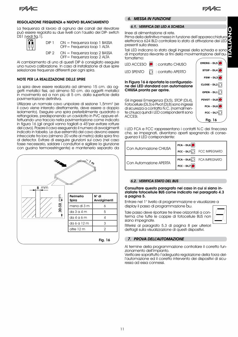
6.1.. VERIFICA.DEI.LED.A.SCHEDA
Fig. 16
6.2.. VERIFICA.STATO.DEL.BUS
Consultare questo paragrafo nel caso in cui si siano in-stallate fotocellule BUS come indicato nel paragrafo 4.3 a pagina 5.Entrare nel �° livello di programmazione e visualizzare a display il passo di programmazione bu.
Tale passo deve riportare tre linee orizzontali a con-ferma che tutte le coppie di fotocellule BUS non siano impegnate.Riferirsi al paragrafo 5.� di pagina 8 per ulteriori dettagli sulla visualizzazione di questi dispositivi.
.7.. PROVA.DELL’AUTOMAZIONE
Al termine della programmazione controllare il corretto fun-zionamento dell’impianto.Verificare soprattutto l’adeguata regolazione della forza del-l’automazione ed il corretto intervento dei dispositivi di sicu-ressa ad essa connessi.
REGOLAZIONE FREQUENZA e NUOVO BILANCIAMENTO
La frequenza di lavoro di ognuno dei canali del rilevatore può essere regolata su due livelli con l’ausilio dei DIP- switch DS� (vedi fig.�).
DIP � ON = Frequenza loop � BASSA OFF= Frequenza loop � ALTA
DIP � ON = Frequenza loop � BASSA OFF= Frequenza loop � ALTAAl cambiamento di uno di questi DIP è consigliato eseguire una nuova calibrazione. In caso di installazione di due spire selezionare frequenze differenti per ogni spira.
NOTE PER LA REALIZZAZIONE DELLE SPIRE
La spira deve essere realizzata ad almeno �5 cm. da og-getti metallici fissi, ad almeno 50 cm. da oggetti metallici in movimento ed a non più di 5 cm. dalla superficie della pavimentazione definitiva. Utilizzare un normale cavo unipolare di sezione �,5mm² (se il cavo viene interrato direttamente, deve essere a doppio isolamento). Eseguire una spira preferibilmente quadrata o rettangolare, predisponendo un cavidotto in PVC oppure ef-fettuando una traccia nella pavimentazione come indicato in figura �6 (gli angoli vanno tagliati a 45°per evitare rotture del cavo). Posare il cavo eseguendo il numero di avvolgimenti indicato in tabella. Le due estremità del cavo devono essere intrecciate fra loro (almeno �0 volte al metro) dalla spira fino al detector. Evitare di eseguire giunzioni sul cavo (nel caso fosse necessario, saldare i conduttori e sigillare la giunzione con guaina termorestringente) e mantenerlo separato da
linee di alimentazione di rete.Prima della definitiva messa in funzione dell’apparecchiatura elettronica 6�4 BLD controllare lo stato di attivazione dei LED presenti sulla stessa.Tali LED indicano lo stato degli ingressi della scheda e sono di importanza rilevante ai fini della movimentazione dell’au-tomatismo:
LED ACCESO : contatto CHIUSO
LED SPENTO : contatto APERTO
In Figura 16 è riportata la configurazio-ne dei LED standard con automazione CHIUSA pronta per aprire.
Gli ingressi Emergenza (DL5), STOP (DL4), Fotocellule (DL�) e Pivot (DL8) sono ingressi di sicurezza a contatto N.C. (normalmen-te chiuso) quindi i LED corrispondenti sono ACCESI.
I LED FCA e FCC rappresentano i contatti N.C dei finecorsa che, se impegnati, diventano aperti spegnendo di conse-guenza il LED corrispondente:
Con Automazione CHIUSAFCC IMPEGNATO
Con Automazione APERTAFCA IMPEGNATO
Perimetro Spira
N° diAvvolgimenti
meno di � m 6
da � a 4 m 5
da 4 a 6 m 4
da 6 a �� m �
oltre �� m �
mm
mm
Fig. 16
~ 1 m
ITA
LIA
NO

��
1 OFF2 OFF
Fig. 17
.8.. CONFIGURAZIONI.MASTER-SLAVE
Qualora l’installazione preveda l’utilizzo di due barriere contrapposte da azionare contemporaneamente in apertura/chiusu-ra del varco, si utilzzi uno dei diagrammi di collegamento sotto riportati in funzione delle schede elettroniche impiegate per movimentare le barriere.
Per apparecchiatura MASTER si intende la scheda elettronica a cui sono collegati tutti i datori di impulso ed i dispositivi di sicurezza.Per apparecchiatura SLAVE si intende la scheda elettronica che viene pilotata dalla MASTER tramite gli ingressi di impulso mentre gli ingressi di sicurezza sono cortocircuitati.
a ...1°.liv..PROGRAMMAZIONE
LO = Cb ...3°.liv..PROGRAMMAZIONE
03 = Yc ...1°.liv..PROGRAMMAZIONE
LO = CU
ITA
LIA
NO

��
La programmazione di �° livello è utilizzata solo nell’eventualità di personalizzazione avanzata delle logiche di funzionamento già presenti in memoria.
Prima.di.effettuare.combiamenti.in.questo.livello,.accertarsi.di.comprendere.appieno.la.natura.dei.passi.che.si.vuole.modificare.e.la.loro.influenza.sull’automazione.
Per accedere alla PROGRAMMAZIONE �° LIVELLO premere il pulsante F e, mantenendolo premuto, premere il pulsante + per circa 10 secondi. L’utilizzo dei tasti F, + e - è il medesimo degli altri due livelli di programmazione.
PROGRAMMAZIONE 3° LIVELLO 10 sec
D. Funzione Impostazione
0 1 Attivando questa funzione si ha la chiusura automatica dopo il tempo pausa. Y = chiusura automaticano = disattiva
02 Attivando questa funzione si ha il funzionamento a due ingressi distinti: OPEN per l’aper-tura e CLOSE per la chiusura.
Y = funzionamento � ingressino = disattiva
03Attivazione del riconoscimento dei livelli degli ingressi OPEN e CLOSE (comando man-tenuto). Ovvero la scheda riconosce il livello (ad esempio con OPEN mantenuto e si preme lo STOP, al rilascio di quest’ultimo l’automazione continua ad aprire). Se 03 è disattivato la scheda comanda una manovra solamente a fronte di una variazione dell’ingresso.
Y = riconoscimento livellono = riconoscimento alla va-
riazione dello stato
04 Attivazione apertura a UOMO PRESENTE (comando sempre premuto). Rilasciando il co-mando OPEN si blocca il funzionamento
Y = attivano = disattiva
05Attivando questa funzione il comando OPEN durante l’apertura arresta il movimento.Se il parametro 06 è no il sistema è pronto per l’apertura.Se il parametro 06 è Y il sistema è pronto per la chiusura.
Y = in apertura bloccano = disattiva
06 Attivando questa funzione il comando OPEN durante l’apertura inverte il movimento.Se i parametri 05 e 06 sono no l’OPEN non ha effetto durante l’apertura.
Y = in apertura inverteno = disattiva
07Attivando questa funzione il comando OPEN durante la pausa blocca il funzionamen-to.Se i parametri 07 e 08 sono no l’OPEN ricarica il tempo pausa.
Y = in pausa bloccano = disattiva
08 Attivando questa funzione il comando OPEN durante la pausa provoca la chiusura.Se i parametri 07 e 08 sono no l’OPEN ricarica il tempo pausa.
Y = in pausa chiudeno = disattiva
09 Attivando questa funzione il comando OPEN durante la chiusura blocca il funzionamen-to, altrimenti inverte il movimento.
Y = bloccano = inverte
10 Attivazione chiusura a UOMO PRESENTE (comando sempre premuto). Rilasciando il coman-do CLOSE si blocca il funzionamento.
Y = attivano = disattiva
1 1 Attivando questa funzione il comando CLOSE ha priorità sull’OPEN, altrimenti l’OPEN ha priorità sul CLOSE.
Y = attivano = disattiva
12 Attivando questa funzione il comando CLOSE comanda la chiusura quando è rilasciato. Finché CLOSE è attivo l’unità rimane in prelampeggio chiusura.
Y = chiude al rilasciono = chiude subito
13Attivando questa funzione il comando CLOSE durante l’apertura blocca il funzionamen-to, altrimenti il comando CLOSE comanda l’inversione immediatamente o al termine dell’apertura (vedi anche parametro 14)
Y = CLOSE bloccano = CLOSE inverte
14 Attivando questa funzione e se il parametro 13 è no, il comando CLOSE comanda la chiusura immediata al termine del ciclo di apertura (memorizza il CLOSE).Se i parametri 13 e 14 sono no CLOSE comanda la chiusura immediata.
Y = chiude alla fine dell’aper-tura
no = chiusura immediata
15 Attivando questa funzione con il sistema bloccato da uno STOP un successivo OPEN muove nella direzione opposta. Se il parametro 15 è no chiude sempre.
Y = muove in direzione oppo-sta
no = chiude sempre
16Attivando questa funzione, durante la chiusura, le SICUREZZE CHIUSURA bloccano e con-sentono la ripresa del moto al loro disimpegno, altrimenti invertono immediatamente in apertura.
Y = chiude al disimpegnono = inversione immediata
17Attivando questa funzione le SICUREZZE CHIUSURA comandano la chiusura al loro di-simpegno(vedi anche parametro 18).
Y = chiusura al disimpegno di FSW
no = disattiva
18 Attivando questa funzione e se il parametro 17 è Y, l’unità attende il termine del ciclo di apertura prima di eseguire il comando di chiusura fornito dalle SICUREZZE CHIUSURA.
Y = chiude alla fine dell’aper-tura
no = disattiva
19 Attivando questa funzione, durante la chiusura, LOOP2 blocca e consente la ripresa del moto al disimpegno, altrimenti inverte immediatamente in apertura.
Y = chiusura al disimpegnono = inversione immediata
20 Attivando questa funzione LOOP2 comanda la chiusura al suo disimpegno (vedi anche parametro 21).
Y = chiude se LOOP� liberono = disattiva
2 1 Attivando questa funzione e se il parametro 20 è Y , l’unità attende il termine del ciclo di apertura prima di eseguire il comando di chiusura fornito da LOOP2.
Y = chiude a fine aperturano = disattiva
22 Attivando questa funzione i comandi di LOOP1 risultano essere prioritari rispetto a quelli di LOOP2.
Y = attivano = disattiva
.9.. PROGRAMMAZIONE.3°.LIVELLO
ITA
LIA
NO

�4
D. Funzione Impostazione
23Il LOOP 1 comanda un’apertura ed al termine della stessa chiude se disimpegnato (utile nel caso di arretramento veicolo con loops consecutivi). Se disattivato al disimpegno di LOOP � non viene effettuata la chiusura.
Y = chiude se LOOP� liberono = disattiva
24 NON UTILIZZATO /
25Funzione A.D.M.A.P.attivando questa funzione si ottiene il funzionamento delle sicurezze conforme alle normative francesi.
Y = attivano = disattiva
26 Attivando questa funzione le SICUREZZE CHIUSURA durante la chiusura bloccano e inver-tono il movimento al loro disimpegno, altrimenti invertono immediatamente.
Y = blocca e inverte al disim-pegno.
no= inverte immediatamen-te.
27 NESSUN EFFETTO /
A 1PRELAMPEGGIO:Permette di regolare, a passi di � sec, la durata del prelampeggio desiderato, da un minimo di 00 ad un massimo di 10 secondi
05
A2TIMEOUT DI INVERSIONE IN CHIUSURA:Attivando questa funzione è possibile durante la chiusura decidere di invertire o bloccare il movimento allo scadere del timeout (mancato raggiungimento il finecorsa di chiusu-ra).
Y = inversioneno = blocco
A3APERTURA ALL’ACCENSIONE:In caso di mancanza di tensione, al ripristino della stessa, è possibile, abilitando questa funzione, comandare un’apertura (solo se l’automazione non è chiusa, FCC libero).
Y = aperturano = rimane fermo
A4TEMPO ATTIVAZIONE PRESSOSTATO FAAC CITY (J5):È il tempo dopo il quale l’unità considera il segnale proveninente dal pressostato come FINECORSA DI CHIUSURA.Regolabile da 00 a 59 sec. a passi di un secondo. In seguito la visualizzazione cambia in minuti e decine di secondi (separati da un punto) fino al valore massimo di 4,1 minuti.
4.0
A5DISATTIVAZIONE PRESSOSTATO DISSUASORI A INIZIO MOVIMENTO: Per un corretto funzionamento del dissuasore è necessario disattivare il controllo del pres-sostato all’inizio della manovra di salita (tempo 0,4 secondi).Impostare questa funzione su Y con dissuasori.
Y = pressostato disattivato allo spunto no = pressostato sempre attivo
A6CONTROLLO ALIMENTAZIONE ELETTROVALVOLA DISSUASORI (morsetti 22-23):FAAC CITY K - J�75K: uscita elettrovalvola normalmente disalimentata - alimentata du-rante la discesa.FAAC CITY - J�75 standard: uscita elettrovalvola normalmente alimentata - disalimenta-ta durante la discesa.
Y = per FAAC CITY K /J�75K no = per FAAC CITY stan-dard e J�75
A7 POLARITA’ FINECORSA D’APERTURA:Configurazione del contatto di finecorsa
Y = polarità NOno = polarità NC
A8 POLARITA’ FINECORSA DI CHIUSURA:Configurazione del contatto di finecorsa
Y = polarità NOno = polarità NC
A9ABILITAZIONE PRESSOSTATO FAAC CITY (J5):
Riconoscimento del contatto PRESSOSTATO come sicurezza durante la prima fase di salita e di finecorsa dopo il tempo di attivazione pressostato FAAC CITY (parametro A4):
Y = Funzionamento per FAAC CITY
no = Funzionamento fine-corsa standard
b0PRESSOSTATO DI SOLA SICUREZZA PER DISSUASORI ( morsetti 7 - GND ):
Riconoscimento del contatto FOTOCELLULA come PRESSOSTATO di sicurezza.(il contatto viene ignorato a inizio movimento e al termine della salita)
Y = Funzionamento del pres-sostato di sola sicurezzano = Funzionamento foto-
cellule standard
b1 RITARDO INTERVENTO FUNZIONE HOLD CLOSE / HOLD OPEN:Tempo di ritardo nell’attivazione della funzione HOLD CLOSE / HOLD OPEN (vedi parametri b� e b4).Il conteggio inizia al raggiungimento del finecorsa interessato.Se al termine del tempo impostato il finecorsa risulta disimpegnato involontariamente viene attivata la funzione HOLD CLOSE / HOLD OPEN. 00 = attivazione immediata di HOLD CLOSE / HOLD OPEN 01 a 99 = minuti di conteggio prima dell’attivazione HOLD CLOSE / HOLD OPEN
30
b2 DA NON MODIFICARE 30b3 FUNZIONE HOLD CLOSE:
Nel caso in cui il finecorsa di chiusura venga involontariamente abbandonato la sche-da comanda in automatico una movimentazione per un tempo di � sec.per tentare di ripristinare la posizione; se in questo tempo il finecorsa di chiusura non viene impegnato l’automazione verrà attivata al massimo per il tempo di lavoro “t” vedi �°LIV. PROGRAM-MAZIONE :
Y = attivano = disattiva
b4 FUNZIONE HOLD OPEN:Nel caso in cui il finecorsa di apertura venga involontariamente abbandonato la scheda comanda in automatico una movimentazione per un tempo di � sec. per tentare di ripristinare la posizione; se in questo tempo il finecorsa di apertura non viene impegnato l’automazione verrà attivata al massimo per il tempo di lavoro “t” vedi �° LIV. PROGRAM-MAZIONE:(consigliato parametro A3 su Y se parametro b4 impostato su Y)
Y = attivano = disattiva
ITA
LIA
NO
�5
Default FAAC1
RISER-VATO FAAC
Default FAAC CITY
Default FAAC CITY K
Default J275
Default J275K
dF pre-setting 0 1 02 03 04 05 06bu BUS
Lo logica E A1 rb rb rb rbPA pausa 20 20 30 30 30 30FO forza 50 50 50 50 50 50L 1 loop � no no no no no noL2 loop � no no no no no noH 1 loop � no no no no no noH 2 loop � no no no no no noS 1 sensibilità 05 05 05 05 05 05S2 sensibilità 05 05 05 05 05 05
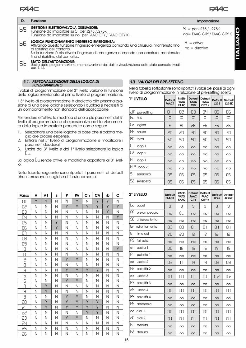
9.1.. PERSONALIZZAZIONE.DELLA.LOGICA.DI. . FUNZIONAMENTO
I valori di programmazione del �° livello variano in funzione della logica selezionata al primo livello di programmazione.
Il �° livello di programmazione è dedicato alla personalizza-zione di una delle logiche selezionabili qualora si necessiti di un comportamento non standard dell’applicazione.
Per rendere effettiva la modifica di uno o più parametri del �° livello di programmazione che personalizzano il funzionamen-to della logica impostata procedere come segue:
Selezionare una delle logiche di base che si adatta me-glio alle proprie esigenze.Entrare nel �° livello di programmazione e modificare i parametri desiderati.Uscire dal �° livello e dal �° livello selezionare la logica Cu.
La logica Cu rende attive le modifiche apportate al �° livel-lo.
Nella tabella seguente sono riportati i parametri di default che interessano le logiche di funzionamento.
�.
�.
�.
Passo A A1 E P PA Cn CA rb C
0 1 Y Y N N Y N Y Y N02 N N N Y Y Y Y Y Y03 N N N N N N N Y N04 N N N N N N N N Y05 N N Y N N N N N N06 N N Y N N N N N N07 N N N N N N N N N08 N N N N N N N N N09 N N N N N N N N N10 N N N N N N N N Y1 1 N N N N N N N N N12 N N N Y Y N N N N13 N N N N N N N N N14 N N N Y Y Y Y N N15 N N N N N N N N N16 N N N Y Y N N N N17 N Y N N N N N N N18 N Y N N N N N N N19 N N N Y Y N N N N20 N Y N Y Y Y Y N N2 1 N Y N Y Y Y Y N N22 N N N N N Y Y N N23 N N N Y Y N N N N24 N N N N N N N N N25 N N N N N N N N N26 N N N N N N N N N
.10.. VALORI.DEI.PRE-SETTING
Nella tabella sottostante sono riportati i valori dei passi di ogni livello di programmazione in relazione al pre-setting scelto
1° LIVELLO
2° LIVELLO
bo boost Y Y Y Y Y YPF prelampeggio no CL no no no noSC chiusura lenta no no no no no notr rallentamento 03 03 0 1 0 1 0 1 0 1t time out 20 20 12 12 12 12FS fail safe no no no no no noo 1 uscita � 00 16 15 15 15 15P 1 polarità � no no no no no noo2 uscita � 03 17 14 14 03 03P2 polarità � no no no no no noo3 uscita � 0 1 0 1 0 1 0 1 0 2 0 2P3 polarità � no no no no no noo4 uscita 4 00 00 00 00 00 00P4 polarità 4 no no no no no noA5 assistenza no no no no no nonc cicli �. 00 00 00 00 00 00nC cicli �. 0 1 0 1 0 1 0 1 0 1 0 1h 1 ritenuta no no no no no noh2 ritenuta no no no no no no
b5 GESTIONE ELETTROVALVOLA DISSUASORI:Funzione da impostare su Y per J�75 /J�75KFunzione da impostare su no per FAAC CITY / FAAC CITY K).
Y = per J�75 / J�75Kno= FAAC CITY / FAAC CITY K
b6 LOGICA FUNZIONAMENTO INGRESSO EMERGENZA:Attivando questa funzione l’ingresso emergenza comanda una chiusura, mantenuta fino al ripristino del contatto.Se la funzione è disattivata l’ingresso di emergenza comanda una apertura, mantenuta fino al ripristino del contatto..
Y = attivano = disattiva
St STATO DELL’AUTOMAZIONE:Uscita dalla programmazione, memorizzazione dei dati e visualizzazione dello stato cancello (vedi par. 5.�.).
D. Funzione Impostazione
Default FAAC1
RISER-VATO FAAC
Default FAAC CITY
Default FAAC CITY K
Default J275
Default J275K
ITA
LIA
NO

�6
____________________________________________________
_____________________________________________________
________________________________________________________________________________________________________
1918
1617
1514
1213
1011
89
67
45
23
1
OPEN A
STOP
LOOP 1
LOOP 2
LOOP 2
LOOP 1
CLOSE
FSW
EMERGENCY
OUT 1
OUT 2
OUT 4
OUT 3
GND
GND
GND
+24 V
+24 V
OUT 3
J119
1816
1715
1412
1310
118
96
74
52
31
OPEN A
STOP
LOOP 1
LOOP 2
LOOP 2
LOOP 1
CLOSE
FSW
EMERGENCY
OUT 1
OUT 2
OUT 4
OUT 3
GND
GND
GND
+24 V
+24 V
OUT 3
J119
1816
1715
1412
1310
118
96
74
52
31
OPEN A
STOP
LOOP 1
LOOP 2
LOOP 2
LOOP 1
CLOSE
FSW
EMERGENCY
OUT 1
OUT 2
OUT 4
OUT 3
GND
GND
GND
+24 V
+24 V
OUT 3
J1
08 no no no no no no09 no no no no no no10 no no no no no no1 1 no no no no no no12 no no no no no no13 no no no no no no14 no no no no no no15 no no no no no no16 no no no no no no17 no Y no no no no18 no Y no no no no19 no no no no no no20 no Y no no no no2 1 no Y no no no no22 no no no no no no23 no no no no no no24 no no no no no no25 no no no no no no26 no no no no no no27 no no no no no noA 1 05 0 1 05 05 05 05A2 no no no no no noA3 no no no no no noA4 4 .0 4 .0 04 04 4 .0 4 .0A5 no no Y Y Y YA6 no no no Y no YA7 no no Y Y no noA8 no no no Y no noA9 no no Y Y no nob0 no no no no Y Yb 1 00 00 30 30 30 30b2 30 30 30 30 30 30b3 no no Y Y Y Yb4 no no no no no nob5 no no no no Y Yb6 no no no no no no
.11.. NOTE
.12.. COLLEGAMENTO.INTERBLOCCO
Per barriere in linea abilitare OUT� INTERBLOCCO al para-metro �8 (vedi PROG. �° LIVEL-LO) su entrambe le schede e collegarle come in fig.�8
La funzione interblocco permette di gestire due barriere in linea (vedi fig.) in maniera tale che l’apertura di una sia subordinata alla chiusura dell’altra.Il funzionamento può essere monodirezionale o bidirezionale.
0 1 no Y Y Y Y Y02 no no Y Y Y Y03 no no Y Y Y Y04 no no no no no no05 Y no no no no no06 Y no no no no no07 no no no no no no
3° LIVELLO Default FAAC1
RISER-VATO FAAC
Default FAAC CITY
Default FAAC CITY K
Default J275
Default J275K
Fig. 18
ITA
LIA
NO

�7
Tab. 1/b
Tab. 1/a
LOGICA “A” IMPULSI
STATO AUTOMAZIONE OPEN A CLOSE STOP FSW LOOP 1 LOOP 2
CHIUSOapre e richiude dopo il tempo
pausanessun effetto nessun effetto
(apertura inibita) nessun effettoapre e richiude dopo il tempo
pausanessun effetto
IN APERTURA nessun effettoinverte in chiu-
sura immediata-mente
blocca il funzionamento nessun effetto nessun effetto nessun effetto
APERTO IN PAUSA ricarica il tempo pausa chiude blocca il
funzionamento
ricarica il tempo pausa
(chiusura inibita)
ricarica il tempo pausa
ricarica il tempo pausa
(chiusura inibita)
IN CHIUSURA inverte in apertura immediatamente nessun effetto blocca il
funzionamento
inverte in aper-tura immediata-
menteinverte in apertura immediatamente
inverte in aper-tura immediata-
mente
BLOCCATO chiude chiudenessun effetto
(apertura e chiu-sura inibite)
nessun effetto (chiusura inibita)
apre e richiude dopo il tempo
pausanessun effetto
(chiusura inibita)
LOGICA “A1” IMPULSI
STATO AUTOMAZIONE OPEN A CLOSE STOP FSW LOOP 1 LOOP 2
CHIUSOapre e richiude dopo il tempo
pausanessun effetto nessun effetto
(apertura inibita) nessun effettoapre e richiude dopo il tempo
pausanessun effetto
IN APERTURA nessun effettoinverte in chiu-
sura immediata-mente
blocca il funzio-namento
chiude imme-diatamente al termine del-
l’aperturanessun effetto
chiude imme-diatamente al termine del-
l’apertura
APERTO IN PAUSA ricarica il tempo pausa chiude blocca il
funzionamento chiude ricarica il tempo pausa chiude
IN CHIUSURA inverte in apertura immediatamente nessun effetto blocca il
funzionamento
inverte in aper-tura immediata-
mente
inverte in apertura immediatamen-te, chiude a fine
pausa
inverte in aper-tura immediata-mente, richiude
ad apertura terminata
BLOCCATO chiude chiudenessun effetto
(apertura e chiu-sura inibite)
nessun effetto (chiusura inibita)
apre e richiude dopo il tempo
pausanessun effetto
(chiusura inibita)
LOGICA “E” IMPULSI
STATO AUTOMAZIONE OPEN A CLOSE STOP FSW LOOP 1 LOOP 2
CHIUSO apre nessun effetto nessun effetto (apertura inibita) nessun effetto apre nessun effetto
IN APERTURA blocca il funziona-mento
inverte in chiu-sura immediata-
mente
blocca il funzionamento nessun effetto nessun effetto nessun effetto
APERTO chiude chiude nessun effetto (chiusura inibita)
nessun effetto (chiusura inibita) chiude nessun effetto
(chiusura inibita)
IN CHIUSURA inverte in apertura immediatamente nessun effetto blocca il
funzionamento
inverte in aper-tura immediata-
menteinverte in apertura immediatamente
inverte in aper-tura immediata-
mente
BLOCCATO chiude chiudenessun effetto
(apertura e chiu-sura inibite)
nessun effetto (chiusura inibita) apre nessun effetto
(chiusura inibita)
Tra parentesi gli effetti sugli altri ingressi a impulso attivo
.13.. TABELLE.LOGICHE.DI.FUNZIONAMENTO
Tab. 1/c
ITA
LIA
NO

�8
Tab. 1/d
Tab. 1/e
Tab. 1/f
LOGICA “P” IMPULSI
STATO AUTOMAZIONE OPEN A CLOSE STOP FSW LOOP 1 LOOP 2
CHIUSO apre nessun effetto nessun effetto (apertura inibita) nessun effetto
apre e al termi-ne dell’apertura
chiude sedisimpegnato
nessun effetto
IN APERTURA nessun effettochiude imme-diatamente al termine del-
l’apertura
blocca il funzionamento nessun effetto nessun effetto
chiude imme-diatamente al termine del-
l’apertura
APERTO nessun effetto(chiusura inibita) chiude nessun effetto
(chiusura inibita)nessun effetto
(chiusura inibita)Impediscela chiusura chiude
IN CHIUSURA inverte in apertura immediatamente nessun effetto blocca il
funzionamento
blocca e al disimpegno continua a chiudere
inverte in apertura immediatamente e al termine del-l’apertura chiude se disimpegnato
blocca e al disimpegno continua a chiudere
BLOCCATO apre chiudenessun effetto
(apertura e chiu-sura inibite)
nessun effetto (chiusura inibita)
apre e al termine dell’apertura chiu-
de se disimpe-gnato
nessun effetto (chiusura inibita)
Tra parentesi gli effetti sugli altri ingressi a impulso attivo
LOGICA “PA” IMPULSI
STATO AUTOMAZIONE OPEN A CLOSE STOP FSW LOOP 1 LOOP 2
CHIUSOapre e richiude dopo il tempo
pausanessun effetto nessun effetto
(apertura inibita) nessun effettoapre e al termi-ne dell’apertura
chiude sedisimpegnato
nessun effetto
IN APERTURA nessun effettochiude imme-diatamente al termine del-
l’apertura
blocca il funzionamento nessun effetto nessun effetto
chiude imme-diatamente al termine del-
l’apertura
APERTO IN PAUSA ricarica il tempo pausa chiude blocca il
funzionamento
ricarica il tempo pausa
(chiusura inibita)
ricarica il tempo di pausa chiude
IN CHIUSURA inverte in apertura immediatamente nessun effetto blocca il
funzionamento
blocca e al disimpegno continua a chiudere
inverte in apertura immediatamente e al termine del-l’apertura chiude se disimpegnato
blocca e al disimpegno continua a chiudere
BLOCCATOapre e richiude dopo il tempo
pausachiude
nessun effetto (apertura e chiu-
sura inibite)nessun effetto
(chiusura inibita)
apre e al termi-ne dell’apertura
chiude sedisimpegnato
nessun effetto (chiusura inibita)
LOGICA “Cn” IMPULSI
STATO AUTOMAZIONE OPEN A CLOSE STOP FSW LOOP 1 LOOP 2
CHIUSO apre nessun effetto nessun effetto (apertura inibita) nessun effetto apre nessun effetto
IN APERTURA nessun effettochiude imme-diatamente al termine del-
l’apertura
blocca il funzionamento nessun effetto nessun effetto
chiude imme-diatamente al termine del-
l’apertura
APERTO nessun effetto(chiusura inibita) chiude nessun effetto
(chiusura inibita)nessun effetto
(chiusura inibita) nessun effetto chiude
IN CHIUSURA inverte in apertura immediatamente nessun effetto blocca il
funzionamento
inverte in aper-tura e chiude
dopo il tempo di pausa
inverte in apertura immediatamente
inverte in aper-tura immediata-
mente
BLOCCATO apre chiudenessun effetto
(apertura e chiu-sura inibite)
nessun effetto (chiusura inibita) apre nessun effetto
(chiusura inibita)
ITA
LIA
NO

�9
Tab. 1/i
Tab. 1/g
Tab. 1/h
LOGICA “CA” IMPULSI
STATO AUTOMAZIONE OPEN A CLOSE STOP FSW LOOP 1 LOOP 2
CHIUSOapre e richiude dopo il tempo
pausanessun effetto nessun effetto
(apertura inibita) nessun effettoapre e richiude dopo il tempo
pausanessun effetto
IN APERTURA nessun effettochiude imme-diatamente al termine del-
l’apertura
blocca il funzionamento nessun effetto nessun effetto
chiude imme-diatamente al termine del-
l’apertura
APERTO IN PAUSA ricarica il tempo pausa chiude blocca il
funzionamento
ricarica il tempo pausa
(chiusura inibita)
ricarica il tempo di pausa chiude
IN CHIUSURA inverte in apertura immediatamente nessun effetto blocca il
funzionamento
inverte in aper-tura e chiude
dopo il tempo di pausa
inverte in apertura immediatamente
inverte in aper-tura immediata-
mente
BLOCCATOapre e richiude dopo il tempo
pausachiude
nessun effetto (apertura e chiu-
sura inibite)nessun effetto
(chiusura inibita)apre e richiude dopo il tempo
pausanessun effetto
(chiusura inibita)
LOGICA “rb” IMPULSI
STATO AUTOMAZIONE OPEN A CLOSE STOP FSW LOOP 1 LOOP 2
CHIUSOapre e richiude dopo il tempo
pausanessun effetto nessun effetto
(apertura inibita) nessun effettoapre e richiude dopo il tempo
pausanessun effetto
IN APERTURA nessun effettoinverte in chiu-
sura immediata-mente
blocca il funzionamento nessun effetto nessun effetto nessun effetto
APERTO IN PAUSA ricarica il tempo pausa chiude blocca il
funzionamento
ricarica il tempo pausa
(chiusura inibita)
ricarica il tempo di pausa
ricarica il tempo pausa
(chiusura inibita)
IN CHIUSURA inverte in apertura immediatamente nessun effetto blocca il
funzionamento
inverte in aper-tura immediata-
menteinverte in apertura immediatamente
inverte in aper-tura immediata-
mente
BLOCCATOapre e richiude dopo il tempo
pausachiude
nessun effetto (apertura e chiu-
sura inibite)nessun effetto
(chiusura inibita)apre e richiude dopo il tempo
pausanessun effetto
(chiusura inibita)
Tra parentesi gli effetti sugli altri ingressi a impulso attivo
LOGICA “C” COMANDI MANTENUTI IMPULSI
STATO AUTOMAZIONE OPEN A CLOSE STOP FSW LOOP 1 LOOP 2
CHIUSO apre nessun effetto nessun effetto (apertura inibita) nessun effetto nessun effetto nessun effetto
IN APERTURA / nessun effetto blocca il funzio-namento nessun effetto nessun effetto nessun effetto
APERTO nessun effetto(chiusura inibita) chiude blocca il funzio-
namento nessun effetto nessun effetto(chiusura inibita)
nessun effetto(chiusura inibita)
IN CHIUSURA inverte in apertura immediatamente / blocca il funzio-
namentoBlocca il
funzionamentoblocca il funziona-
mentoblocca il funzio-
namento
BLOCCATO apre chiudenessun effetto
(apertura e chiu-sura inibite)
nessun effetto (chiusura inibita)
nessun effetto(chiusura inibita)
nessun effetto(chiusura inibita)
ITA
LIA
NO

�
INDEX1....WARNINGS...................................................................................................................................................3
2....TECHNICAL.SPECIFICATIONS........................................................................................................................3
3....LAYOUT.AND.COMPONENTS.OF.624BLD......................................................................................................3
3.1.Description.of.components...................................................................................................................3
4....ELECTRICAL.CONNECTIONS.........................................................................................................................4
4.1...J1.Terminal-board.-.Accessories.(Fig..2).............................................................................................4
4.2...Connection.of.relay.photocells.and.safety.devices.with.“N.C.”.contact................................................ 5
4.3...Connection.of.BUS.photocells.............................................................................................................5
4.4...J2.Terminal-board.-.Motor,.flashing.lamp.and.fan..(Fig..2)................................................................6
4.5...J8.Connector.-.Motor.capacitor.(Fig..2).............................................................................................6
4.6...J9.Terminal-board.-.Power.supply.(Fig..2)...........................................................................................6
4.7...J3,.J5.Rapid.connectors.-.for.opening.and.closing.limit-switches.(Fig..2)..........................................6
4.8...J6.Connector.-.Beam.breaking.sensor.(Fig..2).....................................................................................6
4.9...DS1.Frequency.selector.(Fig..1)....................................................................................................................... 6
4.10.J4.Connector.-.for.Minidec,.Decoder.and.RP.............................................................................................. 6
5....PROGRAMMING...........................................................................................................................................6
5.1...1st.LEVEL.PROGRAMMING....................................................................................................................6
5.2...Modification.of.the.pre-setting...........................................................................................................8
5.3...Setup.and.BUS.system.control......................................................................................................................... 8
5.4...2nd.LEVEL.PROGRAMMING..................................................................................................................9
5.5...Setup.for.integrated.Loop.Detector....................................................................................................10
6....START-UP.......................................................................................................................................................11
6.1...Board.LEDS.check................................................................................................................................11
6.2...Check.on.BUS.status............................................................................................................................11
7....AUTOMATED.SYSTEM.TEST.............................................................................................................................11
8....MASTER-SLAVE.CONFIGURATIONS................................................................................................................12
9....3rd.LEVEL.PROGRAMMING...........................................................................................................................13
9.1...Customisation.of.function.logic..........................................................................................................15
10..PRE-SETTING.VALUES.....................................................................................................................................15
11..NOTES..........................................................................................................................................................16
12..INTERLOCK.CONNECTION............................................................................................................................16
13..FUNCTION.LOGIC.TABLES.............................................................................................................................17
EN
GLIS
H

�
CE DECLARATION OF CONFORMITY
Manufacturer: FAAC S.p.A.
Address: Via Calari, �0 - 40069 Zola Predosa BOLOGNA - ITALY
Declares that: 6�4BLD control unit
• conforms to the essential safety requirements of the following EEC directives
�006/95/EC Low Voltage Directive �004/�08/EC Electromagnetic Compatibility Directive
Additional note: This product underwent tests in a typical uniform configuration (all products manufactured by FAAC S.p.A.).
Bologna, 0� January �0�0
The Managing Director A. Marcellan
1) ATTENTION!Toensurethesafetyofpeople,itisimportantthatyoureadallthefollowinginstructions.Incorrectinstallationorincorrectuseoftheproductcouldcauseseriousharmtopeople.
2) Carefullyreadtheinstructionsbeforebeginningtoinstalltheproduct.
3) Donotleavepackingmaterials(plastic,polystyrene,etc.)withinreachofchildrenassuchmaterialsarepotentialsourcesofdanger.
4) Storetheseinstructionsforfuturereference.
5) Thisproductwasdesignedandbuiltstrictlyfortheuseindicatedinthisdocumentation. Any other use, not expressly indicated here, couldcompromisethegoodcondition/operationoftheproductand/orbeasourceofdanger.
6) FAACdeclinesallliabilitycausedbyimproperuseoruseotherthanthatforwhichtheautomatedsystemwasintended.
7) Donotinstalltheequipmentinanexplosiveatmosphere:thepresenceofinflammablegasorfumesisaseriousdangertosafety.
8) ThemechanicalpartsmustconformtotheprovisionsofStandardsEN12604andEN12605.
Fornon-EUcountries,toobtainanadequatelevelofsafety,theStand-ardsmentionedabovemustbeobserved,inadditiontonationallegalregulations.
9) FAACisnotresponsibleforfailuretoobserveGoodTechniqueintheconstructionoftheclosingelementstobemotorised,orforanydefor-mationthatmayoccurduringuse.
10) TheinstallationmustconformtoStandardsEN12453andEN12445.
Fornon-EUcountries,toobtainanadequatelevelofsafety,theStand-ardsmentionedabovemustbeobserved,inadditiontonationallegalregulations.
11) Beforeattemptinganyjobonthesystem,cutoutelectricalpower.
12) Themainspowersupplyoftheautomatedsystemmustbefittedwithanall-poleswitchwithcontactopeningdistanceof3mmorgreater.Useofa6Athermalbreakerwithall-polecircuitbreakisrecommended.
13) Make sure that a differential switch with threshold of 0.03 A is fittedupstreamofthesystem.
14) Makesurethattheearthingsystemisperfectlyconstructedandcon-nectmetalpartsoftheclosuretoit.
15) Theautomatedsystemissuppliedwithanintrinsicanti-crushingsafetydeviceconsistingofatorquecontrol.Nevertheless,itstrippingthresh-oldmustbecheckedasspecifiedintheStandardsindicatedatpoint10.
16) Thesafetydevices (EN12978standard) protectanydangerareasagainstmechanicalmovementRisks,suchascrushing,dragging,andshearing.
17) Useofatleastoneindicator-light(e.g.FAACLIGHT)isrecommendedforeverysystem,aswellasawarningsignadequatelysecuredtotheframestructure,inadditiontothedevicesmentionedatpoint“16”.
18) FAACdeclinesallliabilityasconcernssafetyandefficientoperationoftheautomatedsystem,ifsystemcomponentsnotproducedbyFAACareused.
19) Formaintenance,strictlyuseoriginalpartsbyFAAC.
20) Do not in any way modify the components of the automated sys-tem.
21) Theinstallershallsupplyallinformationconcerningmanualoperationofthesystemincaseofanemergencyandshallhandovertotheuserthewarningshandbooksuppliedwiththeproduct.
22) Do not allow children or adults to stay near the product while it isoperating.
23) Keepremotecontrolsorotherpulsegeneratorsawayfromchildren,topreventtheautomatedsystemfrombeingactivatedinvoluntarily.
24) Transitispermittedonlywhentheautomatedsystemisidle.
25) Theusermustnotattemptanykindofrepairordirectactionwhateverandcontactqualifiedpersonnelonly.
26) Checkatleastevery6monthstheefficiencyofthesystem,particularlytheefficiencyofthesafetydevices(including,whereforeseen,theoperatorthrustforce)andofthereleasedevices.
27) Anything not expressly specified in these instructions is not permit-ted.
WARNINGSFORTHEINSTALLERGENERALSAFETYOBLIGATIONS
EN
GLIS
H

�
.1.. WARNINGS
Attention: Before attempting any work on the control unit (connections, maintenance), always turn off power.- Install, upstream of the system, a differential thermal breaker with adequate tripping threshold.- Connect the earth cable to the terminal on the J9 connector of the unit (see fig.2).- Always separate power cables from control and safety cables (push-button, receiver, photocells, etc.). To avoid any electrical
noise, use separate sheaths or a screened cable (with the screen earthed).
CONTROL UNIT 624 BLD
.3.. LAYOUT.AND.COMPONENTS.OF.624BLD
Power supply voltage *
��0 V~ (+6% -�0%) - 50/60 Hzor
��5 V~ (+6% -�0%) - 50/60 Hz
Absorbed power 7 W
Motor max. load �000 W
Power supply for accessories �4 Vdc
Accessories max.current 500 mA
Operating ambient temperature from -�0°C to +55°C
Protectionfuses *
F� = F �0A - �50V F� = T 0,8A - �50Vor
F� = F �0A - ��0V F� = T 0,8A - ��0V
Work time Programmable (from 0 to 4 minutes)
Pause time Programmable (from 0 to 4 minutes)
Motor power Programmable on 50 levels
Programming � programming levels for greater flexibility of use
Rapid connector Coupling for 5-pin Minidec board, Decoder, Receiver RP/RP�
Programmableoutputs
4 programmable outputsin �8 different functions
Features
Management of slow-downs, multifunction display, BUS technology
and INTEGRATED METALLIC MASS DETECTOR
* The power supply voltage and fuses depend on the version purchased
.2.. TECHNICAL.SPECIFICATIONS
3.1.DESCRIPTION.OF.COMPONENTS
DL SIGNALS AND PROGRAMMING DISPLAY
LED INPUT STATUS CONTROL LEDs
J1 LOW-VOLTAGE TERMINAL BOARD
J2 TERMINAL BOARD FOR CONNECTION OF MOTOR, FLASHING LAMP AND FAN
J3 OPENING LIMIT-SWITCH CONNECTOR
J4 CONNECTOR FOR DECODER MINIDEC / RP RECEIVER
J5 CLOSING LIMIT-SWITCH CONNECTOR
J6 CONNECTOR FOR ROD BREAKING SENSOR
J8 CONNECTOR FOR MOTOR THRUST CAPACITOR
J9 TERMINAL-BOARD FOR ��0 VAC POWER SUPPLY
DS1 LOOP � and LOOP � FREQUENCIES SELECTOR
F1 FUSE FOR MOTORS AND TRANSFORMER PRIMARY WINDING (F 5A)
F2 FUSE FOR LOW VOLTAGE AND ACCESSORIES (T 800mA)
F PROGRAMMING PUSH-BUTTON “F”
+ PROGRAMMING PUSH-BUTTON “+”
- PROGRAMMING PUSH-BUTTON “-”
TF1 TRANSFORMER
Fig. 1
EN
GLIS
H
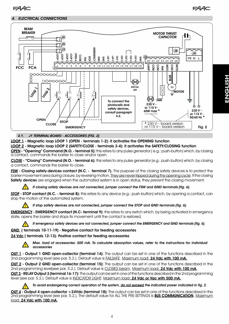
4
.4.. ELECTRICAL.CONNECTIONS
To connect the photocells and safety devices,
consult paragraph 4.2.
BLUE
MOTOR THRUST CAPACITOR
FAN
MOTOR
BEAM BREAKER
Fig. 2
LOOP 1 - Magnetic loop LOOP 1 (OPEN - terminals 1-2): it activates the OPENING functionLOOP 2 - Magnetic loop LOOP 2 (SAFETY/CLOSE - terminals 3-4): it activates the SAFETY/CLOSING function OPEN - “Opening” Command (N.O. - terminal 5): this refers to any pulse generator ( e.g.: push-button) which, by closing a contact, commands the barrier to close and/or open.CLOSE - “Closing” Command (N.O. - terminal 6): this refers to any pulse generator (e.g.: push-button) which, by closing a contact, commands the barrier to close.FSW - Closing safety-devices contact (N.C. - terminal 7). The purpose of the closing safety devices is to protect the barrier movement area during closure, by reversing motion. They are never tripped during the opening cycle. If the closing Safety devices are engaged when the automated system is in open status, they prevent the closing movement.
If.closing.safety.devices.are.not.connected,.jumper.connect.the.FSW.and.GND.terminals.(fig..6).
STOP - STOP contact (N.C. - terminal 8): this refers to any device (e.g.: push-button) which, by opening a contact, can stop the motion of the automated system.
If.stop.safety.devices.are.not.connected,.jumper.connect.the.STOP.and.GND.terminals.(fig..6).
EMERGENCY - EMERGENCY contact (N.C- terminal 9): this refers to any switch which, by being activated in emergency state, opens the barrier and stops its movement until the contact is restored.
If.emergency.safety.devices.are.not.connected,.jumper.connect.the.EMERGENCY.and.GND.terminals.(fig..6).
GND ( terminals 10-11-19) - Negative contact for feeding accessories24 Vdc ( terminals 12-13)- Positive contact for feeding accessories
. Max.. load.of.accessories:.500.mA..To.calculate.absorption.values,.refer.to.the.instructions.for. individual.accessories
OUT 1 - Output 1 GND open-collector (terminal 14): The output can be set in one of the functions described in the �nd programming level (see par. 5.�.). Default value is FAILSAFE. Maximum load: 24 Vdc with 100 mA.OUT 2 - Output 2 GND open-collector (terminal 15): The output can be set in one of the functions described in the �nd programming level(see par. 5.�.). Default value is CLOSED beam. Maximum load: 24 Vdc with 100 mA.OUT 3 - RELAY Output 3 (terminal 16-17): The output can be set in one of the functions described in the �nd programming level (see par. 5.�.). Default value is INDICATOR LIGHT: Maximum load: 24 Vdc or Vac with 500 mA.
. To.avoid.endangering.correct.operation.of.the.system,.do.not.exceed.the.indicated.power.indicated.in.fig..2.
OUT 4 - Output 4 open-collector +24Vdc (terminal 18): The output can be set in one of the functions described in the �nd programming level (see par. 5.�.). The default value for ALL THE PRE-SETTINGS is BUS COMMUNICATION. Maximum load: 24 Vdc with 100 mA.
4.1.. J1.TERMINAL-BOARD.-.ACCESSORIES.(FIG..2)
230 V~or 115 V~60W max * 230 V~
or 115 V~50/60 Hz *
* ��0 V~ board version or ��5 V~ board version
EN
GLIS
H

5
191816 17151412 1310 118 96 74 52 31
OPEN
A
STOP
LOO
P1
LOO
P2
LOO
P2
LOO
P1
CLO
SE
FSW
EMERG
ENC
Y
OUT1
OUT2
OUT4
OUT3
GN
D
GN
D
GN
D
+24V
+24V
OUT3
J1
The 6�4 BLD board envisages the connection of closing.safety.devices which are tripped only during the barrier closing movement, and are therefore suitable for protecting the closing zone against the risk of impact.
. .If.two.or.more.safety.devices.(NC.contacts).have.to.be.connected,.put.them.in.series.with.each.other.as.shown.in.figures.3,.4,.5.under.the.heading.“SAFE”.
4.2.CONNECTION.OF.RELAY.PHOTOCELLS.AND.SAFETY.DEVICES.WITH.“N.C.”.CONTACT
Connection of 1 pair of closure photocells Connection of 2 pairs of closure photocells
Fig. 5
Fig. 3
Connection of no safety device
Fig. 6
4.3.CONNECTION.OF.BUS.PHOTOCELLS
1st Pair of photocells 2nd Pair of photocells
Fig. 7
Photocells using BUS technology are connected to the 6�4 BLD control unit ALL IN PARALLEL as shown in Fig. 7 through single power/communication line.
.TheBUSphotocellsdonothaveconnectionpolarity.
Up to a maximum of 8 pairs of BUS photocells can be connected to the board.The photocells are subdivided by quantity into the following groups:
Pairs of closure photocells: max 7Pairs of photocells for OPEN pulse: max �
Make sure that at the �nd programming level:
o4 = 00 and P4 = no
Connection of 1 pair of closure photocells with FAIL SAFE facility
To be set in the �nd programming level : FS = Y and o 1 = 00Fig. 4
EN
GLIS
H

6
RP / RP2
624BLDJ4
4.4.. J2. TERMINAL-BOARD. -. MOTOR,. FLASHING. LAMP.AND..FAN.(FIG..2)
M (COM-MOT1-MOT2): Motor ConnectionLAMP (LAMP-COM): Flashing lamp output FAN (FAN-COM): Fan output
4.6.. J9.TERMINAL-BOARD.-.POWER.SUPPLY.(FIG..2)
PE : Earth connectionN : Power supply ��0 V~ or ��5 V~( Neutral )L : Power supply ��0 V~ or ��5 V~( Line )
. . For. correct. operation,. the. board. must.be.connected.to.the.earthing.conductor.present. in. the. system.. Install,. upstream.of. the. system,. a. differential. thermal.breaker.
4.5.. J8.CONNECTOR.-.MOTOR.CAPACITOR.(FIG..2)
Rapid connector for connecting the motor thrust capacitor.
4.7.. J3,. J5. RAPID. CONNECTORS. -. FOR. OPENING. AND.CLOSING.LIMIT-SWITCHES.(FIG..2)
Quick-fit connector for connection of the opening (J�) and closing (J5) limit-switches.
After positioning of the BUS technology photocells, select the address of each pair through the combination of the DIP-SWITCHES present on each photocell.
.. Set. THE. SAME. DIP-SWITCH. ADDRESS. .chosen.on.both. the. transmitter.and. the.receiver.of.the.same.pair.
..Make. sure. that. there. are. not. two. or.more. pairs. of. photocells. with. the. same.address
. . If..no.BUS.accessory.is.used,.leave.terminals.18.and.19.free.
Table 4 shows the programming of the dip-switches present within the transmitter and receiver of the BUS photocells.Tab. 4 - Address of PAIRS of BUS photocells
Dip1 Dip2 Dip3 Dip4 Pairnumber Type
ON OFF OFF OFF �st pair
CLOSURE Photocells
ON OFF OFF ON �nd pair
ON OFF ON OFF �rd pair
ON OFF ON ON 4th pair
ON ON OFF OFF 5th pair
ON ON OFF ON 6th pair
ON ON ON OFF 7th pair
ON ON ON ON SinglePair
OPEN PULSE
DIP-SWITCHTX
DIP-SWITCHRX
SAME ADDRESS
. To. make. the. installed. Bus. accessories.operat iona l , . per form. on-board.memorisation. as. explained. in. chapter.5.3.
4.10..J4.CONNECTOR.-.FOR.MINIDEC,.DECODER.AND.RP
It is used for rapid connection of Minidec, Decoder and RP/RP� Receivers.If you are using an RP� twin-channel receiver, you will be able to directly command the automated system’s OPEN and CLOSE from a twin-channel radio control.If using a single-channel RP type receiver, only OPEN can be commanded.Fit the accessory with the component side directed toward the board interior.
. Insert.and.remove.the.boards.ONLY.after.cutting.power.
4.8...J6.CONNECTOR.-.BEAM.BREAKING.SENSOR.(FIG..2)
Quick-fit connector for connecting the beam breaking sensor (where present). If this sensor is absent, leave the supplied jumper in place.
4.9.. DS1.FREQUENCY.SELECTOR.(FIG..1)DIP-SWITCH selector used to set a HIGH or LOW working frequency of the vehicle loop detectors. Consult chapter 5.5.
modif icat ion of the programming parameters is immediately effective,whereasdefinitivememory-storageoccursonlyonexitingprogrammingandreturningtotheviewoftheautomatedsystemstatus.Ifyoucutpowertotheunitbeforereturningtoviewthestatus,allthemodificationsmadewillbelost.
You can return to viewing the status fromanypointofprogrammingatanylevel,bypressingkeysFand-simultaneously.
.5.. PROGRAMMINGTo programme the operation of the automated system, the“PROGRAMMING”mode must be accessed. Programming is in three parts: 1stLEVEL,2ndLEVELand3rdLEVEL.
5.1.. 1ST.LEVEL.PROGRAMMING
To access �st LEVEL PROGRAMMING, use push-button F:
• if you press it (and hold it down), the display shows the name of the first function.
• if you release the push-button, the display shows the value of the function, which can be changed with keys + and -.
An example of a radio accessory connection
Fig. 8
EN
GLIS
H

7
• if you press F again (and hold it down), the display shows the name of the next function, etc.
• when you reach the last function, press the push-button F to exit programming, and the display resumes showing the inputs status.
1ST LEVEL PROGRAMMING
Display Function Default
dFLOADING PARAMETERS:
00 Neutral condition0 1 Default FAAC � loaded02 Default RESERVED FOR FAAC03 Default FAAC CITY loaded04 Default FAAC CITY K loaded05 Default J�75 loaded06 Default J�75K loaded
LEAVE AT 00 IF YOU DO NOT WISH TO MAKE ANY CHANGE TO THE PROGRAMMING.For an explanation of the dF parameter refer to page.8.chapter.5.2.
00
buBUS ACCESSORY MENUFor an explanation of this parameter refer to page.8.chapter.5.3.
LOFUNCTION LOGICS:
A AutomaticA 1 Automatic �E SemiautomaticP ParkingPA Parking automaticCn CondoCA Condo automaticrb Faac-City ( traffic bollard logic )C Dead-manr RemoteCu Custom
E
PAPAUSE TIME:
This operates only if an automatic logic was selected. Can be adjusted from 0 to 59 sec. in � second steps. Subsequently, the display changes to show minutes and tenths of a second (separated by a dot) and time is adjusted in �0 second steps, up to the maximum value of 4 . 1 minutes.e.g. if the display shows 2.5, the pause time will be � min and 50 sec.
20
FOPOWER:Adjusts motor power. 0 1 = minimum power 50 = maximum power
50
L 1LOOP 1:If this function is enabled, the loop connected to the Loop� input will have the OPEN function. Y = loop� active n o = loop� not active Attention: if the function is not enabled, loop� status will nevertheless be available on one of the outputs, if appropriately set (see second level programming).
no
Display Function Default
L2 LOOP 2:If this function is enabled, the loop connected to Loop� input will have the SAFETY/CLOSE function, i.e. it will operate as SAFETY during the closing stage, and will command CLOSE to the board at release. Y = loop� active n o = loop� not activeAttention: if the function is not enabled, loop� status will nevertheless be available on one of the outputs, if appropriately set.
no
H1 BOOST LOOP 1 FUNCTION
Y = Active no = Not activeThanks to this function you can increase the sensitivity level at the moment of detection. When the vehicle leaves the loop, the sensitivity returns to the selected level. This system holds the detection contact even in the event of very high vehicles as well as during the passage of a tractor with trailer.
no
H2 BOOST LOOP 2 FUNCTION
Y = Active no = Not activeSee BOOST LOOP� function.
no
S 1 SENSITIVITY LOOP 1Regulates the sensitivity of the loop: 0 1 = minimum 1 0 = maximum
05
S2 SENSITIVITY LOOP 2Regulates the sensitivity of the loop: 0 1 = minimum 1 0 = maximum
05
StAUTOMATED SYSTEM STATUS:Exit programming,memory storage of data set and return to automated system status view.
00 Closed
0 1 Opening pre-flashing
02 Opening
03 Open
04 In pause
05 Closing pre-flashing
06 Closing
07 Stopped ready to close
08 Stopped ready to open
09 Emergency opening
10 Closing safety device in operation
ThedisplayoftheautomatedsystemstatusSt isoffundamentalimportancefortheoperatorassignedtoinstallation/maintenance,todistinguishthelogicalprocessestheboardperformsduringmovements.If,forexample,theautomatedsystemisinCLOSEDstate00mustbeshownonthedisplay.OnreachingthecommandOPEN,thedisplaywillchangeto0 1 , if pre-flashing is enabled,ordirectly to02 (theOPENINGmovement),tothendisplay03onreachingtheOPENposition.
EN
GLIS
H

8
Example of sequence of states displayed starting from barrier closed:
In the sequence, states 0 1 and 05 are not shown; these correspond to pre-flashing at opening and at closing, respectively.
00 Closed 02 Opening
04 Pause (if present)
03 Open
06 Closing
5.2.. MODIFICATION.OF.THE.PRE-SETTING.
The modification of the dF parameter enables you to automatically load 6 different configurations modifying all programming values at every level with preset values.This possibility is a convenient starting point for subsequent rapid ‘fine tuning’ of the 6�4 BLD for functioning with 6 different types of installation.
6 PRE-SETTINGS may be selected:
0 1 Default FAAC for barriers 02 Default RESERVED FOR FAAC03 Default for the FAAC CITY �75 H600 and H800 range04 Default for FAAC CITY �75 H700 K05 Default for J�7506 Default for J�75K
To implement loading of the values of one of the 6 pre-settings, select the required pre-setting ( 0 1 , 02 , 03, 04 , 05 , 06 ) and exit 1st level programming.
EXAMPLE: selecting 0 1 and exiting �st level programming, all the FAAC default values which can be found in the �st, �nd and �rd level tables in the “Default” column are loaded. The 6�4 BLD is therefore configured for movement of a barrier.
. THE.LOADING.OF.A.PRE-SETTING.CANCELS.ALL.THE.MODIFICATIONS.PREVIOUSLY.MADE.AT.ANY.PROGRAMMING.STEP..IF.YOU.DO.NOT.WISH.TO.LOAD.ANY.. PRE-SETTING,.LEAVE.THE..dF .STEP.AT.00.
The dF, step, unlike the others, does not store the value selected but returns to show 00 again, as standard condition.
It is therefore not possible to identify what pre-setting was previously set.
If you do not wish to load any pre-setting, ALWAYS leave the dF step at value 00 and move on to the following programming step.
Ensure. that. you. load. the. desired. default. and.exit. 1st. level. programming. BEFORE. modifying.other. steps,. in. order. to. avoid. deleting. all. the.modifications.made.
To learn more about the specifications of each pre-setting, refer to chapter �0 on page �5.
5.3.. SETUP.and.BUS.SYSTEM.CONTROLEach time you install one or more BUS accessories (as explained in chapter 4.�) these must be stored on the board.Storage is performed as follows:- enter the first programming level as explained in chapter.
5.�;- at the bu programming step, release programming
push-button F and press push-button + for � second.
The display shows -- for an instant and then returns to the standard condition indicated in fig. �0. The storage procedure is finished.The bu programming step also has the function of displaying the status of the BUS technology accessories. Figure 9 indicates the exact correspondence between the segments of the display and the inputs.
Fig. 9
Segment ON = closed contactSegment OFF = open contact
FSW CL = BUS photocells closing
OPEN = BUS photocell pulse generators OPENNO
T USE
D
The configuration for correct operation of the automated system should show the three horizontal segments ON as in figure 10.
In case of engagement of the closure photocells, the upper and lower segments switch off, leaving the central segment on, as in figure ��.
In case of engagement of the PULSE GENERATOR OPEN pair, the corresponding vertical segment switches on for the engagement time of the pair, as illustrated in figure ��.
Fig. 10
Fig. 11
Fig. 12
The PULSE GENERATOR OPEN pair of photocells, if engaged, commands opening of the application and prevents its closure until it is released.
If no pair of BUS photocells is present on the system, the bu programming step will still show the display in figure 10.
The BUS communication system uses a self-diagnostic function able to supply reports of incorrect connection or of erroneous configuration of the BUS accessories.
The display shows the cc signal FLASHING when a SHORT-CIRCUIT is present along the BUS line, as in figure ��. Check the connections made (chapter.4.�).
The display shows the Er message FLASHING, as in figure �4, if more than one pair of photocells should have the same address.
Fig. 13
Fig. 14
In this latter case, check all the addresses set on all the photocells installed, referring to chapter 4.�.
EN
GLIS
H

9
2ND LEVEL PROGRAMMING
Display Function De-fault
bo MAXIMUM THRUST TORQUE:the motor runs at maximum torque (ignoring torque regulation) at the initial moment of movement.
Y = Active no = Excluded
Y
PF PRE-FLASHING:it permits activation of the flashing lamp for 5 secs before the start of movement.
no excluded
OC before each movement
PA at end of pause only
CL before closing
no
SC SLOW CLOSING:for setting the entire closing stage at slow speed.
Y = Active no = Excluded
no
tr DECELERATION TIME AFTER LIMIT SWITCHES:for setting the deceleration time (in seconds) after the opening and closing limit switches have operated.Can be adjusted from 0 to 10 sec. in � second steps.
0 0 = deceleration excluded 1 0 = maximum deceleration
03
t WORK TIME (time-out):A value should be set from 5 to �0 seconds longer than the time required for the automated system to move from the closed position to the open position, and vice-versa.Can be adjusted from 0 to 59 sec. in � second steps.Subsequently, the display changes to show minutes and tenths of a second (separated by a dot) and time is adjusted in �0 second steps, up to the maximum value of 4.1 minutes.
20
FS FAIL SAFE:If this function is activated, it enables a function test of the photocells before any automated system movement, independently of the output used. If the test fails, the automated system does not start the movement.
Y = Active no = Excluded
no
5.4.. 2nd.LEVEL.PROGRAMMING
To access �nd LEVEL PROGRAMMING, press push-button F and, while holding it down, press push-button +:• if you release the + push-button, the display shows the
name of the first function.• if you also release the F push-button, the display shows the
value of the function, which can be changed with keys + and -.
• if you press the F key (and hold it down), the display shows the name of the next function; if you release it, the value is shown and can be modified with keys + and -.
• when you reach the last function, press push-button F to exit programming, and the display resumes showing the inputs status.
o 1 OUTPUT 1:The output can be set to one of the following functions:
00 FAILSAFE
0 1 INDICATOR LIGHT (lighted at opening and pause, flashing at closing and off when automated system closed).
02 BEAM LIGHTING (output active with beam closed and on pause, inactive with beam open, flashing during movement)
03 beam CLOSED
04 beam OPEN or in PAUSE, it goes off during closing pre-flashing.
05 beam MOVING AT OPENING, pre-flashing included.
06 beam MOVING AT CLOSING, pre-flashing included.
07 beam STILL
08 beam in EMERGENCY status
09 LOOP� engaged
10 LOOP� engaged
1 1 OPEN for 6�4 SLAVE
12 CLOSE for 6�4 SLAVE
13 beam DETACHED
14 bollard lights
15 bollard buzzer
16 FCA engaged
17 FCC engaged
18 interlock
00
P 1 OUTPUT 1 POLARITY:For configuring the output polarity status. Y = N.C. polarity no = N.O. polarity
Note: if the output is set to FAIL-SAFE ( 00 ) leave the default value no .
no
o2 OUTPUT 2:See output � 03
P2 OUTPUT 2 POLARITY:See output � polarity no
o3 OUTPUT 3:See output � 0 1
P3 OUTPUT 3 POLARITY:See output � polarity no
o4 OUTPUT 4 / BUS:If set at 00 the output is dedicated to accessories with BUS technology. Refer to chapter 4.3 on page 5 for an explanation.This output retains the possibility of configuration of output � with the exception of functions 1 1 , 12 , 18 which in this case have no effect.
00
P4 OUTPUT 4 POLARITY:For configuring the output polarity status.
Y = N.C. polarity no = = N.O. polarity (for BUS)
no
EN
GLIS
H

�0
AS ASSISTANCE REQUEST (coupled to the next two functions):If activated at the end of the count-down (settable with the next two functions under “Cycle programming”), it activates LAMP output for 4 sec every �0 sec. (assistance request). Can be useful for setting scheduled maintenance.
Y = Active no = Excluded
no
nc CYCLE PROGRAMMING IN THOUSANDS:For setting a count-down of the system operating cycles, settable value from 0 to 99 (thousands of cycles). The displayed value is reset as the cycles progress, interacting with the nC value (99 nc decrementing steps correspond to one nC decrement).The function can be used combined with nC , to check the use of the system and to make use of the “Assistance request”.
00
nC CYCLE PROGRAMMING IN HUNDREDS OF THOUSANDS:For setting a count-down of the system operating cycles, settable value from 0 to 99 (hundreds of thousands of cycles). The displayed value is reset as the cycles progress, interacting with the nc . (� nc decrement corresponds to 99 nC decrementing steps).The function can be used combined with nc , to check the use of the system and to make use of the “Assistance request”.
0 1
h 1 HOLD TIME LOOP 1For setting the presence time on loop �. At the end of this time the board calibrates itself and indicates “loop free” (decimal point of the units OFF). On switching on the board, an automatic reset is performed.
Y = 5 minutes no = infinite
no
h2 HOLD TIME LOOP 2For setting the presence time on loop �. At the end of this time, the board calibrates itself and indicates “loop free” (decimal point of the tens OFF). On switching on the board, an automatic reset is performed. Y = 5 minutes no = infinite
no
St AUTOMATED SYSTEM STATUS:Exit programming, memory storage of data and return to gate status display (see paragraph 5.�.).
5.5.. SETUP.FOR.INTEGRATED.LOOP.DETECTOR.
The 6�4 BLD is equipped with an integrated metallic mass detector for induction detection of vehicles.Features:
galvanic separation between the electronics of the detector and of the loop automatic alignment of the system immediately after activationcontinual resetting of frequency driftssensitivity independent of loop inductivityregulation of the working frequency of the loopsmessage of loop engaged with LED displayloop status addressable on the OUT �, OUT �, OUT � and OUT 4 outputs
•
•
•••••
Point ON = Loop ENGAGED Point OFF = Loop DISENGAGEDPoint FLASHING = Loop NOT CONNECTED or BEING CALIBRATED
LOOP � LOOP �
REGULATION OF SENSITIVITYRegulating the sensitivity determines the variation of the inductivity, for each channel, which a vehicle must cause to activate the relative output of the detector.Regulation of sensitivity is performed separately for each channel with the aid of the two S1 and S2 parameters at the �st programming level. You can also activate the BOOST function for both detectors. Consult chapter 5.�.
REGULATION OF HOLD TIMEThe retaining time count starts on engagement of the loop. If, on expiry of this time, the loop is still engaged, a new calibration is performed automatically where the presence of the metallic mass on the loop no longer causes its engagement. At the end of the new calibration, the loop is considered “disengaged”.The retaining time can be regulated with the aid of the two h 1 and h2 parameters at the �nd programming level.
Connection:
Connect the loop detectors as indicated in figure � on page 4:
- Terminals � - � for LOOP � = loop with opening function;
- Terminals � - 4 for LOOP � = loop with closing and/or closing safety function.
To learn more about the effect of signals originating from the loops on the automated system, please refer to the logic tables in chapter ��.
To enable the function of the connected loops, enter the 1st programming level and set steps L1 and L2 in Y. To enable the function of the connected loops, enter the 1st programming level and set steps.The operating status of the loop detector is shown through the use of decimal points on the display when automated system status is displayed (step St ).
CALIBRATION
Each time the 6�4 BLD board is powered, the display shows the automated system status and the integrated loop detector calibrates the connected loops. Therefore, perform a calibration, removing power from the 6�4 BLD for at least 5 seconds.
Calibration is shown on the display through flashing of the two points, as in figure �5.
. If.one.or.both.the.magnetic.loops.are.not.installed,.the.loop.detector.is.continually.calibrated.without.this.creating.problems.to.the.functioning.of.the.board..Therefore,.during.display.of.the.automated.system.status,.one.or.both.the.decimal.points.will.flash.constantly.
Once calibration has taken place, the decimal points indicate the loop status:
Fig. 15
EN
GLIS
H

��
.6.. START-UP
6.1.. BOARD.LEDS.CHECK
Fig. 16
6.2.. CHECK.ON.BUS.STATUS
Consult this paragraph if BUS photocells have been installed, as indicated in paragraph 4.3 on page 5.Enter �st programming level and show the bu programming step on the display.
This step must show three horizontal lines, confirming that all pairs of BUS photocells are not engaged.Refer to paragraph 5.� on page 8 for further details on displaying these devices.
.7.. AUTOMATED.SYSTEM.TEST
When you have finished programming, check if the system is operating correctly.Check in particular if power of the automated system is adequately adjusted and if the safety devices connected to it operate correctly.
Consult chapter 5.4 FREQUENCY REGULATION and NEW BALANCING
The working frequency of each of the detector channels can be regulated at two levels with the aid of the DS� DIP- switch (see fig.�).
DIP � ON = Loop � frequency LOW OFF= Loop � frequency HIGH
DIP � ON = Loop � frequency LOW OFF= Loop � frequency HIGHOn changing one of these DIPs, it is recommended that a new calibration be performed. In case of installation of two loops, select different frequencies for each loop.
NOTES FOR CONSTRUCTION OF THE LOOPSThe loop must be located at least �5 cm. from fixed metal objects, at least 50 cm. from moving metal objects and not more than 5 cm. from the road surface. Use a normal single-core cable with a section of �.5 mm² (if the cable is buried directly, it must be double insulated). Construct a loop, preferably square or rectangular, preparing a PVC cable duct or making a track in the flooring as indicated in figure �6 (the angles must be cut at 45° to avoid cable breakage). Place the cable, performing the number of windings indicated in the table. The two ends of the cable must be intertwined (at least �0 times per metre) from the loop to the detector. Avoid any cable splicing (if it should be necessary, solder the wires and seal the junction with a thermo-shrinking
sheath) and keep it separate from power supply lines.Before the definitive start-up of the 6�4 BLD unit, control the activation status of the LEDs present.These LEDs indicate the status of the board inputs and have particular importance for the handling of the automated system:
LED ON : CLOSED contact
LED OFF : OPEN contact
Figure 16 shows the configuration of the standard LEDs with the automated system CLOSED ready to open.
The Emergency inputs (DL5), STOP (DL4), Photocells (DL�) and Pivot (DL8) are safety inputs with N.C. (normally closed) contacts, therefore the corresponding LEDs are ON.
The FCA and FCC LEDs are the N.C contacts of the limit switches which, if engaged, become open, consequently switching off the corresponding LED:
With Automated system CLOSED FCC ENGAGED
With Automated system OPEN
FCA ENGAGED
LoopPerimeter
No. ofWindings
less than � m 6
from � to 4 m 5
from 4 to 6 m 4
from 6 to �� m �
over �� m �
mm
mm
Fig. 16
EN
GLIS
H

��
1 OFF2 OFF
Fig. 17
.8.. MASTER-SLAVE.CONFIGURATIONS
If installation contemplates the use of two opposing barriers to be activated at the same time on opening/ closing, one of the connection diagrams shown below should be used, depending on the control boards used to move the barriers.
By MASTER equipment is meant the control board to which all the pulse generators and safety devices are connected.By SLAVE equipment is meant the control board which is controlled by the MASTER through pulse inputs, while the safety inputs are short-circuited.
a ...1ST.LEVEL.PROGRAMMING
LO = Cb ...3rd.LEVEL.PROGRAMMING
03 = Yc ...1ST.LEVEL.PROGRAMMING
LO = CU
EN
GLIS
H

��
The �rd level programming is only used in the case of advanced customisation of the function logics already present in the memory.
Before.making.changes.at.this.level,.be.sure.you.fully.understand.the.nature.of.the.steps.you.wish.to.modify.and.their.effect.on.the.automated.system.
To access �rd LEVEL PROGRAMMING, press push-button F and, while holding it down, press push-button + for about 10 seconds. Use of the F, + and - keys is the same as for the other two programming levels.
.9.. 3rd.LEVEL.PROGRAMMING
3rd LEVEL PROGRAMMING 10 secs
D. Function Setting
0 1 If you enable this function, automatic closure occurs after pause time. Y = automatic closureno = disables
02 If you enable this function, operation is with two different inputs: OPEN for opening and CLOSE for closing.
Y = operation on two inputsno = disables
03Activation of recognition of the levels of the OPEN and CLOSE inputs (command maintained). That is to say, the board recognises the level (for example, with OPEN maintained and STOP pressed, on release of the latter the automated system continues to open). If 03 is disabled, the board commands a manoeuvre only if the input is varied.
Y = recognition of levelno = recognition of the
change in status
04 Activation of DEAD MAN opening (command kept pressed). If the OPEN command is released, operation is stopped.
Y = enablesno = disables
05If you enable this function, an OPEN command during opening stops the movement.If parameter 06 is no the system is ready for opening.If parameter 06 is Y the system is ready for closing.
Y = at opening stops movementno = disables
06 If you enable this function, an OPEN command during opening reverses movement.If parameters 05 and 06 are no OPEN has no effect during opening.
Y = at opening reversesno = disables
07 If you enable this function, an OPEN command during the pause stops operation.If parameters 07 and 08 are no OPEN recharges pause time.
Y = in pause stops movementno = disables
08 If you enable this function, an OPEN command during the pause causes closure.If parameters 07 and 08 are no l’OPEN recharges pause time.
Y = in pause closesno = disables
09 If you enable this function, an OPEN command during closure, stops operation, otherwise it reverses movement.
Y = stopsno = reverses
10 DEAD MAN closing enabled (command kept pressed). If you release the CLOSE command, operation is stopped.
Y = enablesno = disables
1 1 If you enable this function, a CLOSE command has priority over OPEN, otherwise OPEN has priority over CLOSE.
Y = enablesno = disables
12 If you enable this function, a CLOSE command commands closure when it is released. Until CLOSE is enabled, the unit remains in closure pre-flashing.
Y = closes when releasedno = closes at once
13If you enable this function, a CLOSE command during opening stops operation, otherwise the CLOSE command commands reversing immediately or at end of opening (also see parameter 14)
Y = CLOSE stops movementno = CLOSE reverses
14 If you enable this function, and if parameter 13 is no, the CLOSE command commands immediate closure at end of opening cycle (memory stores CLOSE). If parameters 13 and 14 are no CLOSE commands immediate closure.
Y = closes at the end of opening
no = immediate closure
15 If you enable this function, when the system is stopped by a STOP, a subsequent OPEN command moves in the opposite direction. If parameter 15 is no t always closes.
Y = moves in the opposite direction
no = always closes
16If you enable this function, during closing, the CLOSING SAFETY DEVICES stop movement and allow resumption of movement when disengaged, otherwise they immediately rever-se at opening.
Y = closes at disengagementno = immediate reversing
17If you enable this function, the CLOSING SAFETY DEVICES command closure when disengaged(also see parameter 18).
Y = closure when FSW disengaged
no = disables
18 If you enable this function, and if parameter 17 is Y, the unit waits for the opening cycle to end before executing the closing command supplied by the CLOSING SAFETY DEVICES.
Y = closes at the end of opening
no = disables
19 If you enable this function, during closing, LOOP2 stops movement and allows it to resume at disengagement, otherwise it immediately reverses at opening.
Y = closure at disengagementno = immediate reversing
20 If you enable this function, LOOP2 commands closing when it disengages (also see parameter 21).
Y = closes if LOOP� is freeno = disables
2 1 If you enable this function, and if parameter 20 is Y , the unit waits for the opening cycle to end before executing the closing command supplied by LOOP2.
Y = closes at the end of opening
no = disables
22 If you enable this function, LOOP1 commands have priority over LOOP2 commands.Y = enables
no = disables
EN
GLIS
H

�4
D. Function Setting
23LOOP 1 commands opening and, at end of opening, closes if released (useful if a vehicle reverses with consecutive loops).If disabled at disengagement of LOOP �, no closure is performed.
Y = closes if LOOP� is freeno = disables
24 NOT USED /
25 A.D.M.A.P functionIf you enable this function, the safety devices operate according to French standards.
Y = enablesno = disables
26 If you enable this function, during closure, the CLOSING SAFETY DEVICES stop movement and, when disengaged, reverse movement, otherwise they reverse immediately.
Y = stops movement and reverses when disengaged.
no= reverses immediately.
27 NO EFFECT /
A 1PRELAMPEGGIO:Used for adjusting - in � sec steps - the duration of required pre-flashing, from a minimum of 0 to a maximum of 10 seconds
05
A2TIMEOUT FOR REVERSING AT CLOSURE:If you enable this function, during closing, you can decide whether to reverse or stop the movement when time out elapses (closing stroke limit not reached).
Y = reversalno = block
A3OPENING AT POWER UP:In case of a power cut, when power is restored, an opening operation can be commanded by enabling this function (only if the automated system is not closed, FCC free).
Y = openingno = stays idle
A4TIME FOR ENABLING FAAC CITY PRESSURE SWITCH (J5):This is the time after which the unit considers the signal originating from the pressure switch as the CLOSING TRAVEL-LIMIT.Can be adjusted from 0 to 59 sec. in � second steps. Subsequently, the display changes to show minutes and tenths of a second (separated by a dot), up to a maximum value of 4,1 minutes.
4.0
A5DISABLING OF BOLLARD PRESSURE SWITCH AT START OF MOVEMENT: For a correct operation of the bollard, you have to disable the pressure switch check at start of the upstroke movement (time: 0.4 seconds).Set this function to Y with bollards.
Y = pressure switch not active at thrust no = pressure switch always active
A6BOLLARD SOLENOID VALVE POWER SUPPLY CHECK (terminals 22-23):FAAC CITY K - J�75K: solenoid valve output usually not supplied with power – supplied with power during downstroke.FAAC CITY - J�75 standard: standard: solenoid valve output usually supplied with power – not supplied with power during downstroke.
Y = for FAAC CITY K /J�75K no = for FAAC CITY standard and J�75
A7 POLARITY OF OPENING TRAVEL-LIMIT STOP:Configuration of the travel-limit stop contact
Y = NO polarityno = NC polarity
A8 POLARITY OF CLOSING TRAVEL-LIMIT STOP:Configuration of the travel-limit stop contact
Y = NO polarityno = NC polarity
A9FAAC CITY PRESSURE SWITCH ENABLE (J5):Detection of the PRESSURE SWITCH contact as safety device during the first upstroke phase and as limit switch after activation time of FAAC CITY pressure switch (parameter A4):
Y = Operation for FAAC CITYno = Standard limit switch
operation
b0SAFETY ONLY PRESSURE SWITCH FOR BOLLARDS (terminals 7 - GND):
Recognition of PHOTOCELL contact as a safety PRESSURE SWITCH.(The contact is ignored at start of movement and at the end of the upstroke)
Y = Operation of safety only pressure switchno = Operation of standard
photocells
b 1 HOLD CLOSE / HOLD OPEN FUNCTION DELAY:Delay of the activation of the HOLD CLOSE / HOLD OPEN function (see parameters b� and b4). The count starts when the involved limit switch has been reached.If, at the end of the set time, the limit switch is involuntarily disengaged, the HOLD CLOSE / HOLD OPEN function is activated. 00 = HOLD CLOSE / HOLD OPEN function activated immediately 01 to 99 = minutes of count before activation of HOLD CLOSE / HOLD OPEN
30
b2 DO NOT MODIFY 30b3 HOLD CLOSE FUNCTION:
If the closing limit switch is involuntarily disengaged, the board commands automatically a movement for � sec. to restore the position; if the closing limit switch is not engaged during this period of time, the automated system is activated max. for the operating time “t” see �nd PROGRAMMING LEVEL
Y = enables no = disables
b4 HOLD OPEN FUNCTION:If the opening limit switch is involuntarily disengaged, the board comman-ds automatically a movement for � sec. to restore the position; if the ope-ning limit switch is not engaged during this period of time, the automated sy-stem is activated max. for the operating time “t” see �nd PROGRAMMING LEVEL: (parameter A3 recommended on Y if parameter b3 set on Y):
Y = enables no = disables
EN
GLIS
H

�5
9.1.. CUSTOMISATION.OF.FUNCTION.LOGIC
The �rd programming level values vary depending on the logic selected at the first programming level.
The �rd programming level is dedicated to customisation of one of the logics selectable if non-standard behaviour of application should be needed.
Procedure for implementing the modification of one or more �rd programming level parameters which customise the function of the logic set:
Select one of the basic logics most suitable for your requirements.Enter the �rd programming level and modify the required parameters.Exit the �rd programming level and select logic Cu.
The Cu logic activates the modifications made at the �rd level.
The following table contains the default parameters affecting the function logics.
�.
�.
�.
Step A A1 E P PA Cn CA rb C
0 1 Y Y N N Y N Y Y N02 N N N Y Y Y Y Y Y03 N N N N N N N Y N04 N N N N N N N N Y05 N N Y N N N N N N06 N N Y N N N N N N07 N N N N N N N N N08 N N N N N N N N N09 N N N N N N N N N10 N N N N N N N N Y1 1 N N N N N N N N N12 N N N Y Y N N N N13 N N N N N N N N N14 N N N Y Y Y Y N N15 N N N N N N N N N16 N N N Y Y N N N N17 N Y N N N N N N N18 N Y N N N N N N N19 N N N Y Y N N N N20 N Y N Y Y Y Y N N2 1 N Y N Y Y Y Y N N22 N N N N N Y Y N N23 N N N Y Y N N N N24 N N N N N N N N N25 N N N N N N N N N26 N N N N N N N N N
.10.. PRE-SETTING.VALUES.
The table below shows the values of the steps at each programming level in relation to the pre-setting chosen
1st LEVEL
2nd LEVEL
b5 CONTROL OF BOLLARDS SOLENOID VALVE:Function to be set to Y for J�75 /J�75KFunction to be set to no for FAAC CITY / FAAC CITY K.
Y = for J�75 / J�75Kno= FAAC CITY / FAAC CITY K
b6 EMERGENCY INPUT OPERATING LOGIC:If you activate this function, the emergency input commands a closure, which is kept until the contact is restored.If the function is not active, the emergency input commands an opening, which is kept until the contact is restored.
Y = activeno = not active
St AUTOMATED SYSTEM STATUS:Exit programming, memory storage of data and return to gate status display (see par. 5.�.).
D. Function Setting
Default FAAC1
RESERVED
FOR FAAC
Default FAAC CITY
Default FAAC CITY K
Default J275
Default J275K
dF pre-setting 0 1 02 03 04 05 06bu BUS
Lo logic E A1 rb rb rb rbPA pause 20 20 30 30 30 30FO power 50 50 50 50 50 50L 1 loop � no no no no no noL2 loop � no no no no no noH 1 loop � no no no no no noH 2 loop � no no no no no noS 1 sensitivity 05 05 05 05 05 05S2 sensitivity 05 05 05 05 05 05
bo boost Y Y Y Y Y YPF pre-flashing no CL no no no noSC slow closing no no no no no notr slow-down 03 03 0 1 0 1 0 1 0 1t time out 20 20 12 12 12 12FS fail safe no no no no no noo 1 output � 00 16 15 15 15 15P 1 polarity � no no no no no noo2 output � 03 17 14 14 03 03P2 polarity � no no no no no noo3 output � 0 1 0 1 0 1 0 1 0 2 0 2P3 polarity � no no no no no noo4 output 4 00 00 00 00 00 00P4 polarity 4 no no no no no noA5 assistance no no no no no nonc cycles �. 00 00 00 00 00 00nC cycles �. 0 1 0 1 0 1 0 1 0 1 0 1h 1 hold no no no no no noh2 hold no no no no no no
Default FAAC1
RESERVED
FOR FAAC
Default FAAC CITY
Default FAAC CITY K
Default J275
Default J275K
EN
GLIS
H

�6
____________________________________________________
_____________________________________________________
________________________________________________________________________________________________________
1918
1617
1514
1213
1011
89
67
45
23
1
OPEN A
STOP
LOOP 1
LOOP 2
LOOP 2
LOOP 1
CLOSE
FSW
EMERGENCY
OUT 1
OUT 2
OUT 4
OUT 3
GND
GND
GND
+24 V
+24 V
OUT 3
J119
1816
1715
1412
1310
118
96
74
52
31
OPEN A
STOP
LOOP 1
LOOP 2
LOOP 2
LOOP 1
CLOSE
FSW
EMERGENCY
OUT 1
OUT 2
OUT 4
OUT 3
GND
GND
GND
+24 V
+24 V
OUT 3
J119
1816
1715
1412
1310
118
96
74
52
31
OPEN A
STOP
LOOP 1
LOOP 2
LOOP 2
LOOP 1
CLOSE
FSW
EMERGENCY
OUT 1
OUT 2
OUT 4
OUT 3
GND
GND
GND
+24 V
+24 V
OUT 3
J1
.11.. NOTES
.12.. INTERLOCK.CONNECTION
The interlock function controls two in-line barriers (see fig.) so that the opening of a barrier is interlocked with the closure of the other barrier.The operation can be one-way or bidirectional
Fig. 18
08 no no no no no no09 no no no no no no10 no no no no no no1 1 no no no no no no12 no no no no no no13 no no no no no no14 no no no no no no15 no no no no no no16 no no no no no no17 no Y no no no no18 no Y no no no no19 no no no no no no20 no Y no no no no2 1 no Y no no no no22 no no no no no no23 no no no no no no24 no no no no no no25 no no no no no no26 no no no no no no27 no no no no no noA 1 05 0 1 05 05 05 05A2 no no no no no noA3 no no no no no noA4 4 .0 4 .0 04 04 4 .0 4 .0A5 no no Y Y Y YA6 no no no Y no YA7 no no Y Y no noA8 no no no Y no noA9 no no Y Y no nob0 no no no no Y Yb 1 00 00 30 30 30 30b2 30 30 30 30 30 30b3 no no Y Y Y Yb4 no no no no no nob5 no no no no Y Yb6 no no no no no no
0 1 no Y Y Y Y Y02 no no Y Y Y Y03 no no Y Y Y Y04 no no no no no no05 Y no no no no no06 Y no no no no no07 no no no no no no
Default FAAC1
RESERVED
FOR FAAC
Default FAAC CITY
Default FAAC CITY K
Default J275
Default J275K
3rd LEVEL
For in-line barriers, enable OUT� INTERLOCK on parameter �8 (see �nd PROGRAMMING LEVEL) on both boards and connect them as shown in fig. �8
EN
GLIS
H

�7
Tab. 1/b
Tab. 1/a
LOGIC “A” PULSES
AUTOMATED SYSTEM STATUS OPEN A CLOSE STOP FSW LOOP 1 LOOP 2
CLOSEDopens and
re-closes after pause time
no effectno effect (opening disabled)
no effectopens and
re-closes after pause time
no effect
OPENING no effectreverses
immediately at closing
stops operation no effect no effect no effect
OPEN IN PAUSE recharges pause time closes stops
operation
recharges pause time
(closing disabled)
recharges pause time
recharges pause time
(closing disabled))
CLOSINGreverses
immediately at opening
no effect stops operation
reverses immediately at
opening
reverses immediately at
opening
reverses immediately at
opening
STOPPED closes closesno effect
(opening and closing disabled)
no effect (closing disabled)
opens and re-closes after
pause time
no effect (closing disabled)
LOGIC “A1” PULSES
AUTOMATED SYSTEM STATUS OPEN A CLOSE STOP FSW LOOP 1 LOOP 2
CLOSEDopens and
re-closes after pause time
no effectno effect (opening disabled)
no effectopens and
re-closes after pause time
no effect
OPENING no effectreverses
immediately at closing
stops operation
closes immediately at end of opening
no effectcloses
immediately at end of opening
OPEN IN PAUSE recharges pause time closes stops
operation closes recharges pause time closes
CLOSINGreverses
immediately at opening
no effect stops operation
reverses immediately at
opening
reverses immediately at
opening, closes at pause end
reverses immediately at opening,
re-closes when opening finished
STOPPED closes closesno effect
(opening and closing disabled)
no effect (closing disabled)
opens and re-closes after
pause time
no effect (closing disabled)
LOGIC “E” PULSES
AUTOMATED SYSTEM STATUS OPEN A CLOSE STOP FSW LOOP 1 LOOP 2
CLOSED opens no effectno effect (opening disabled)
no effect opens no effect
OPENING stops operation
reverses immediately at
closing
stops operation no effect no effect no effect
OPEN closes closesno effect (closing disabled)
no effect (closing
disabled)closes
no effect (closing disabled)
CLOSINGreverses
immediately at opening
no effect stops operation
reverses immediately at
opening
reverses immediately at
opening
reverses immediately at
opening
STOPPED closes closesno effect
(opening and closing disabled)
no effect (closing disabled)
opensno effect (closing disabled)
In brackets the effects on the other active pulse inputs
.13.. FUNCTION.LOGIC.TABLES
Tab. 1/c
EN
GLIS
H

�8
Tab. 1/d
Tab. 1/e
Tab. 1/f
LOGIC “P” PULSES
AUTOMATED SYSTEM STATUS OPEN A CLOSE STOP FSW LOOP 1 LOOP 2
CLOSED opens no effectno effect (opening disabled)
no effect opens and at end of opening closes
if disengagedno effect
OPENING no effectcloses
immediately at end of opening
stops operation no effect no effect
closes immediately at end of opening
OPENno effect (closing disabled)
closesno effect (closing disabled)
no effect (closing disabled)
prevents closure closes
CLOSINGreverses
immediately at opening
no effect stops operation
stops and continues to
close on release
reverses immediately at opening and closes at end of opening if disengaged
stops and continues to
close on release
STOPPED opens closesno effect
(opening and closing disabled)
no effect (closing disabled)
opens and at end of opening closes
if disengaged
no effect (closing disabled)
In brackets the effects on the other active pulse inputs
LOGIC “PA” PULSES
AUTOMATED SYSTEM STATUS OPEN A CLOSE STOP FSW LOOP 1 LOOP 2
CLOSEDopens and
re-closes after pause time
no effectno effect (opening disabled)
no effectopens and at end of opening closes
if disengagedno effect
OPENING no effectcloses
immediately at end of opening
stops operation no effect no effect
closes immediately at end of opening
OPEN IN PAUSE recharges pause time closes stops
operation
recharges pause time
(closing disabled)
recharges pause time closes
CLOSINGreverses
immediately at opening
no effect stops operation
stops and continues to
close on release
reverses immediately at
opening and closes at end of opening if
disengaged
stops and continues to
close on release
STOPPEDopens and
re-closes after pause time
closesno effect
(opening and closing disabled)
no effect (closing disabled)
opens and at end of opening closes
if disengaged
no effect (closing disabled)
LOGIC “Cn” PULSES
AUTOMATED SYSTEM STATUS OPEN A CLOSE STOP FSW LOOP 1 LOOP 2
CLOSED opens no effectno effect (opening disabled)
no effect opens no effect
OPENING no effectcloses
immediately at end of opening
stops operation no effect no effect
closes immediately at end of opening
OPENno effect (closing disabled)
closesno effect (closing disabled)
no effect (closing disabled)
no effect closes
CLOSINGreverses
immediately at opening
no effect stops operation
reverses at opening and closes after pause time
reverses immediately at
opening
reverses immediately at
opening
STOPPED opens closesno effect
(opening and closing disabled)
no effect (closing disabled)
opensno effect (closing disabled)
EN
GLIS
H

�9
Tab. 1/i
Tab. 1/g
Tab. 1/h
LOGIC “CA” PULSES
AUTOMATED SYSTEM STATUS OPEN A CLOSE STOP FSW LOOP 1 LOOP 2
CLOSEDopens and
re-closes after pause time
no effectno effect (opening disabled)
no effectopens and
re-closes after pause time
no effect
OPENING no effectcloses
immediately at end of opening
stops operation no effect no effect
closes immediately at end of opening
OPEN IN PAUSE recharges pause time closes stops
operation
recharges pause time
(closing disabled)
recharges pause time closes
CLOSINGreverses
immediately at opening
no effect stops operation
reverses at opening and
closes after pause time
reverses immediately at
opening
reverses immediately at
opening
STOPPEDopens and
re-closes after pause time
closesno effect
(opening and closing disabled)
no effect (closing disabled)
opens and re-closes after
pause time
no effect (closing disabled)
LOGIC “rb” PULSES
AUTOMATED SYSTEM STATUS OPEN A CLOSE STOP FSW LOOP 1 LOOP 2
CLOSEDopens and
re-closes after pause time
no effectno effect (opening disabled)
no effectopens and
re-closes after pause time
no effect
OPENING no effectreverses
immediately at closing
stops operation no effect no effect no effect
OPEN IN PAUSE recharges pause time closes stops
operation
recharges pause time
(closing disabled)
recharges pause time
recharges pause time
(closing disabled)
CLOSINGreverses
immediately at opening
no effect stops operation
reverses immediately at
opening
reverses immediately at
opening
reverses immediately at
opening
STOPPEDopens and
re-closes after pause time
closesno effect
(opening and closing disabled)
no effect (closing disabled)
opens and re-closes after
pause time
no effect (closing disabled)
In brackets the effects on the other active pulse inputs
LOGIC “C” MAINTAINED COMMANDS PULSES
AUTOMATED SYSTEM STATUS OPEN A CLOSE STOP FSW LOOP 1 LOOP 2
CLOSED opens no effectno effect (opening disabled)
no effect no effect no effect
OPENING / no effect stops operation no effect no effect no effect
OPEN no effect (closing disabled)
closes stops operation no effect
no effect (closing disabled)
no effect (closing disabled)
CLOSINGreverses
immediately at opening
/ stops operation
Stops operation
stops operation
stops operation
STOPPED opens closesno effect
(opening and closing disabled)
no effect (closing disabled)
no effect (closing disabled)
no effect (closing disabled)
EN
GLIS
H

�
INDEX1....AVERTISSEMENTS..........................................................................................................................................3
2....CARACTÉRISTIQUES.TECHNIQUES..................................................................................................................3
3....LAYOUT.ET.COMPOSANTS.624BLD................................................................................................................3
3.1.Description.des.composants.................................................................................................................3
4....CONNEXIONS.ÉLECTRIQUES.........................................................................................................................4
4.1...Bornier.J1.-.Accessoires.(Fig..2)...........................................................................................................4
4.2...Connexion.des.photocellules.à.RELAIS.et.des.dispositifs.de.sécurité.avec.un.contact.“N.F.”............. 5
4.3...Connexion.des.photocellules.BUS.......................................................................................................5
4.4...Bornier.J2.-.Moteur,.lampe.clignotante.et.ventilateur.(Fig..2)............................................................6
4.5...Connecteur.J8.-.Condensateur.moteur.(Fig..2)..................................................................................6
4.6...Bornier.J9.-.Alimentation.(Fig..2).........................................................................................................6
4.7...Connecteurs.J3,.J5.-.Embrochage.rapide.de.fin.de.course.d’ouverture.et.fermeture.(Fig..2).........6
4.8...Connecteur.J6.-.Capteur.de.défoncement.de.la.lisse..(Fig..2)............................................................6
4.9...Sélecteur.de.fréquence.DS1.(Fig..1)............................................................................................................... 6
4.10.Connecteur.J4.-.Embrochage.Minidec,.Decoder.et.RP............................................................................. 6
5....PROGRAMMATION.......................................................................................................................................6
5.1...PROGRAMMATION.1er.NIVEAU..............................................................................................................6
5.2...Modification.du.pre-setting.................................................................................................................8
5.3...Sélection.et.côntrole.du.système.BUS............................................................................................................ 8
5.4...PROGRAMMATION.2e.NIVEAU...............................................................................................................9
5.5...Sélection.Loop.Detector.intégré.........................................................................................................10
6....MISE.EN.FONCTION......................................................................................................................................11
6.1...Vérification.des.LEDS...........................................................................................................................11
6.2...Vérification.de.l’état.du.BUS.................................................................................................................11
7....ESSAI.DE.L’AUTOMATISME.............................................................................................................................11
8....CONFIGURATIONS.MASTER-SLAVE................................................................................................................12
9....PROGRAMMATION.DE.3e.NIVEAU..................................................................................................................13
9.1...Personnalisation.de.la.logique.de.fonctionnement............................................................................15
10..VALEURS.DES.PRE-SETTING............................................................................................................................15
11..REMARQUES.................................................................................................................................................16
12..CONNEXION.DE.L’INTERBLOCAGE.................................................................................................................16
13.TABLEAUX.DES.LOGIQUES.DE.FONCTIONNEMENT..........................................................................................17
FRA
NÇ
AIS

�
DÉCLARATION CE DE CONFORMITÉ
Fabricant: FAAC S.p.A.
Adresse: Via Calari, �0 - 40069 - Zola Predosa BOLOGNA - ITALIE
Déclare que: L'armoire électronique 6�4BLD
• est conforme aux conditions essentielles de sécurité requises par les directives suivantes
�006/95/CE directive Basse Tension �004/�08/CE directive Compatibilité Électromagnétique
Note supplémentaire: Ce produit a été soumis à des essais dans une configuration typique homogène
(tous les produits sont fabriqués par FAAC S.p.A.).
Bologna, le �er janvier �0�0
L’Administrateur Délégué A. Marcellan
AVERTISSEMENTS POUR L’INSTALLATEUROBLIGATIONS GÉNÉRALES DE SÉCURITÉ
1) ATTENTION!Ilestimportant,pourlasécuritédespersonnes,desuivreàlalettretouteslesinstructions.Uneinstallationerronéeouunusageerronéduproduitpeutentraînerdegravesconséquencespourlespersonnes.
2) Lireattentivementlesinstructionsavantd'installerleproduit.
3) Les matériaux d'emballage (plastique, polystyrène, etc.) ne doiventpasêtrelaissésàlaportéedesenfantscarilsconstituentdessourcespotentiellesdedanger.
4) Conserverlesinstructionspourréférencesultérieures.
5) Ceproduitaétéconçuetconstruitexclusivementpourl'usageindiquédanslaprésentedocumentation.Touteautreutilisationnonexpressémentindiquéepourraitcompromettrel'intégritéduproduitet/oureprésenterunesourcededanger.
6) FAACdéclinetouteresponsabilitéquidériveraitdel'usageimpropreoudifférentdeceluiauquell'automatismeestdestiné.
7) Nepasinstallerl'appareildansuneatmosphèreexplosive:laprésencedegazoudefuméesinflammablesconstitueungravedangerpourlasécurité.
8) Lescomposantsmécaniquesdoivent répondreauxprescriptionsdesNormesEN12604etEN12605.
PourlesPaysextra-CEE,l'obtentiond'unniveaudesécuritéappropriéexigenonseulementlerespectdesnormesnationales,maiségalementlerespectdesNormessusmentionnées.
9) FAAC n'est pas responsable du non-respect de la Bonne Techniquedanslaconstructiondesfermeturesàmotoriser,nidesdéformationsquipourraientintervenirlorsdeleurutilisation.
10) L'installationdoitêtreeffectuéeconformémentauxNormesEN12453etEN12445.
Pourlespaysextra-CEE,l'obtentiond'unniveaudesécuritéappropriéexigenonseulementlerespectdesnormesnationales,maiségalementlerespectdesNormessusmentionnées.
11) Couper l'alimentation électrique avant toute intervention surl'installation.
12) Prévoir,surlesecteurd'alimentationdel'automatisme,uninterrupteuromnipolaire avec une distance d'ouverture des contacts égale ousupérieureà3mm.Ilestconseilléd'utiliserunmagnétothermiquede6Aavecinterruptionomnipolaire.
13) Vérifierqu'ilyait,enamontdel'installation,uninterrupteurdifférentielavecseuilde0,03A.
14) Vérifierquelamiseàlaterreestréaliséeselonlesrèglesdel'artetyconnecterlespiècesmétalliquesdelafermeture.
15) L'automatisme dispose d'une sécurité intrinsèque anti-écrasement,forméed'uncontrôleducouple.Ilesttoutefoisnécessaired'envérifierleseuild'interventionsuivantlesprescriptionsdesNormesindiquéesaupoint10.
16) Lesdispositifsdesécurité(normeEN12978)permettentdeprotégerdeszoneséventuellementdangereusescontrelesRisquesmécaniquesdumouvement,commel'écrasement,l'acheminement,lecisaillement.
17) On recommande que toute installation soit dotée au moins d'unesignalisation lumineuse (par ex. : FAACLIGHT), d'un panneau designalisationfixé,demanièreappropriée,surlastructuredelafermeture,ainsiquedesdispositifscitésaupoint«16».
18) FAAC décline toute responsabilité quant à la sécurité et au bonfonctionnement de l'automatisme si les composants utilisés dansl'installationn'appartiennentpasàlaproductionFAAC.
19) Pourl'entretien,utiliserexclusivementdespiècesFAACd'origine.
20) Ne jamais modifier les composants faisant partie du systèmed'automatisme.
21) L'installateur doit fournir toutes les informations relatives aufonctionnementmanueldusystèmeencasd'urgenceetremettreàl'Usagerquiutilisel'installationles«instructionspourl'usager»fourniesavecleproduit.
22) Interdireauxenfantsouauxtiersdestationnerprèsduproduitdurantlefonctionnement.
23) Eloignerdelaportéedesenfantslesradiocommandesoutoutautregénérateurd'impulsions,pourévitertoutactionnementinvolontairedel'automatisme.
24) Letransitn'estpermisquelorsquel'automatismeestimmobile.
25) L'Usagerquiutilisel'installationdoitévitertoutetentativederéparationou d'intervention directe et s'adresser uniquement à un personnelqualifié.
26) Entretien:procéderaumoinstouslessixmoisàlavérificationfonctionnelledel'installation,enfaisantparticulièrementattentionàl'efficiencedesdispositifs de sécurité (y compris, lorsqu'elle est prévue, la force depousséedel'opérateur)etdedéverrouillage.
27) Tout ce qui n'est pas prévu expressément dans ces instructions estinterdit.
FRA
NÇ
AIS

�
.1.. AVERTISSEMENTS
Attention: Avant tout type d’intervention sur l’armoire électronique (connexions, entretien), toujours couper le courant électrique.
- Prévoir en amont de l’installation un disjoncteur magnétothermique différentiel au seuil d’intervention adéquat.- Connecter le câble de terre à la borne prévue sur le connecteur J9 de l’armoire (voir fig.2).- Toujours séparer les câbles d’alimentation des câbles de commande et de sécurité (bouton-poussoir, récepteur, photocellules,
etc.). Pour éviter toute perturbation électrique, utiliser des gaines séparées ou un câble blindé (blindage connecté à la masse).
ARMOIRE ÉLECTRONIQUE 624 BLD
.3.. LAYOUT.ET.COMPOSANTS.624BLD
Tension d’alimentation *
��0 V~ (+6% -�0%) - 50/60 Hzou
��5 V~ (+6% -�0%) - 50/60 Hz
Puissance absorbée 7 W
Charge maxi Moteur �000 W
Alimentationaccessoires �4 Vcc
Courant maxiaccessoires 500 mA
Températured’utilisation de -�0°C à +55°C
Fusibles deprotection *
F� = F �0A - �50V F� = T 0,8A - �50Vou
F� = F �0A - ��0V F� = T 0,8A - ��0V
Temps de fonctionnement Programmable (de 0 à 4 min.)
Temps de pause Programmable (de 0 à 4 min.)
Force du moteur Programmable sur 50 niveaux
Programmation � niveaux de programmation pour une plus grande flexibilité d’emploi
Connecteur rapideEmbrochage carte à 5 broches Minidec,
Decoder, Récepteur, RP/RP�
Sortiesprogrammables
4 sorties programmablesen �8 fonctions différentes
Caractéristiques
Gestion des ralentissements, Afficheur multifonction, technologie BUS et
DÉTECTEUR DE MÉTAUXINTÉGRÉ
* La tension d’alimentation et les fusibles varient en fonction de la version de l’armoire
.2.. CARACTÉRISTIQUES.TECHNIQUES
3.1.DESCRIPTION.DES.COMPOSANTS
DL AFFICHEUR DE SIGNALISATION ET DE PROGRAMMATION
LED LEDS DE CONTRÔLE DE L’ÉTAT DES ENTRÉES
J1 BORNIER BASSE TENSION
J2 BORNIER DE CONNEXION DU MOTEUR, LAMPE CLIGNOTANTE ET VENTILATEUR
J3 CONNECTEUR FIN DE COURSE D’OUVERTURE
J4 CONNECTEUR DECODER / MINIDEC / RÉCEPTEUR RP
J5 CONNECTEUR FIN DE COURSE DE FERMETURE
J6 CONNECTEUR CAPTEUR DE DÉFONCEMENT LISSE
J8 CONNECTEUR CONDENSATEUR DE DÉMARRAGE DU MOTEUR
J9 BORNIER D’ALIMENTATION ��0 VCA
DS1 SÉLECTEUR DE FRÉQUENCES LOOP � et LOOP �
F1 FUSIBLE MOTEURS ET PRIMAIRE TRANSFORMATEUR (F 5A)
F2 FUSIBLE BASSE TENSION ET ACCESSOIRES (T 800mA)
F BOUTON-POUSSOIR DE PROGRAMMATION “F”
+ BOUTON-POUSSOIR DE PROGRAMMATION “+”
- BOUTON-POUSSOIR DE PROGRAMMATION “-”
TF1 TRANSFORMATEUR
Fig. 1
FRA
NÇ
AIS
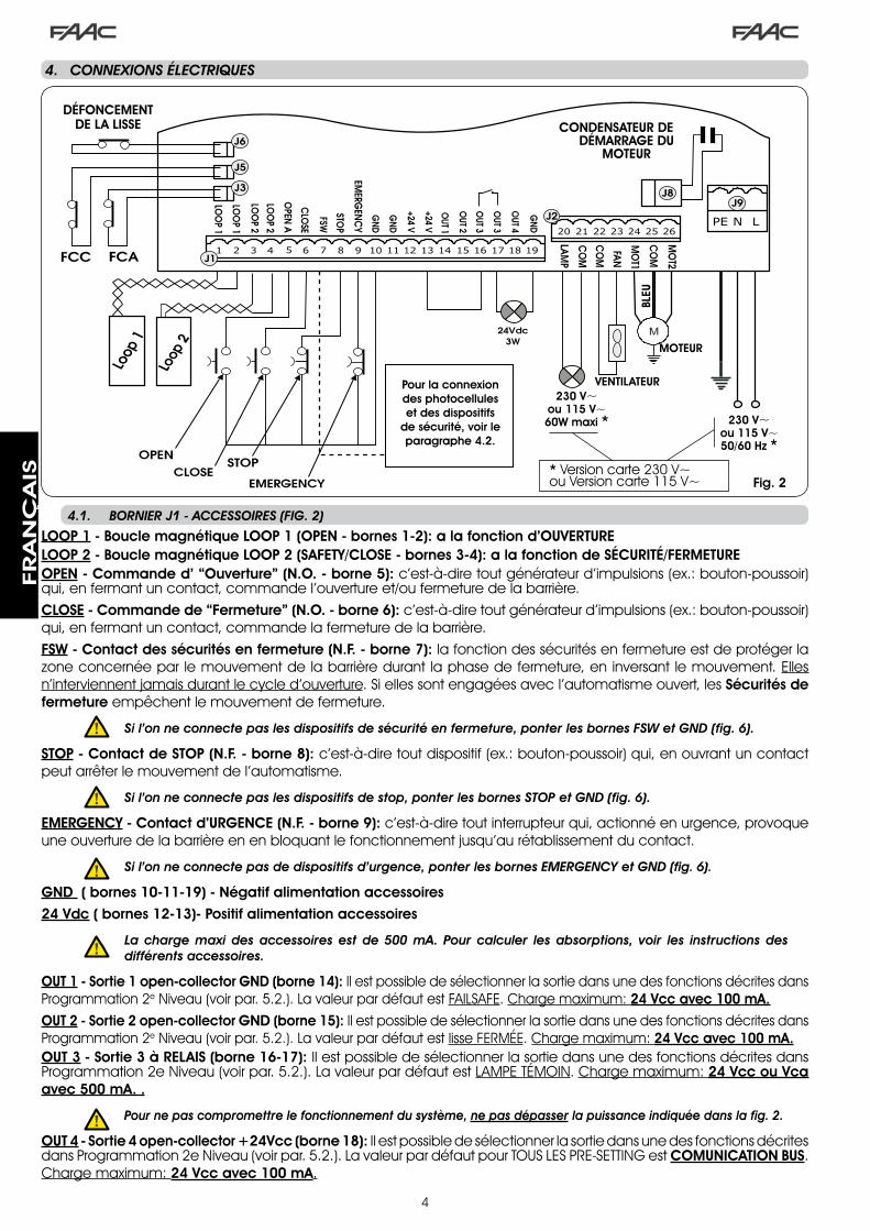
4
.4.. CONNEXIONS.ÉLECTRIQUES
Pour la connexion des photocellules et des dispositifs
de sécurité, voir le paragraphe 4.2.
BLEU
CONDENSATEUR DE DÉMARRAGE DU
MOTEUR
VENTILATEUR
MOTEUR
DÉFONCEMENTDE LA LISSE
Fig. 2
LOOP 1 - Boucle magnétique LOOP 1 (OPEN - bornes 1-2): a la fonction d’OUVERTURELOOP 2 - Boucle magnétique LOOP 2 (SAFETY/CLOSE - bornes 3-4): a la fonction de SÉCURITÉ/FERMETUREOPEN - Commande d’ “Ouverture” (N.O. - borne 5): c’est-à-dire tout générateur d’impulsions (ex.: bouton-poussoir) qui, en fermant un contact, commande l’ouverture et/ou fermeture de la barrière.CLOSE - Commande de “Fermeture” (N.O. - borne 6): c’est-à-dire tout générateur d’impulsions (ex.: bouton-poussoir) qui, en fermant un contact, commande la fermeture de la barrière.FSW - Contact des sécurités en fermeture (N.F. - borne 7): la fonction des sécurités en fermeture est de protéger la zone concernée par le mouvement de la barrière durant la phase de fermeture, en inversant le mouvement. Elles n’interviennent jamais durant le cycle d’ouverture. Si elles sont engagées avec l’automatisme ouvert, les Sécurités de fermeture empêchent le mouvement de fermeture.
Si.l’on.ne.connecte.pas.les.dispositifs.de.sécurité.en.fermeture,.ponter.les.bornes.FSW.et.GND.(fig..6).
STOP - Contact de STOP (N.F. - borne 8): c’est-à-dire tout dispositif (ex.: bouton-poussoir) qui, en ouvrant un contact peut arrêter le mouvement de l’automatisme.
Si.l’on.ne.connecte.pas.les.dispositifs.de.stop,.ponter.les.bornes.STOP.et.GND.(fig..6).
EMERGENCY - Contact d’URGENCE (N.F. - borne 9): c’est-à-dire tout interrupteur qui, actionné en urgence, provoque une ouverture de la barrière en en bloquant le fonctionnement jusqu’au rétablissement du contact.
Si.l’on.ne.connecte.pas.de.dispositifs.d’urgence,.ponter.les.bornes.EMERGENCY.et.GND.(fig..6).
GND ( bornes 10-11-19) - Négatif alimentation accessoires24 Vdc ( bornes 12-13)- Positif alimentation accessoires
. La. charge. maxi. des. accessoires.est. de. 500. mA.. Pour. calculer. les.absorptions,. voir. les. instructions.des.différents.accessoires.
OUT 1 - Sortie 1 open-collector GND (borne 14): Il est possible de sélectionner la sortie dans une des fonctions décrites dans Programmation �e Niveau (voir par. 5.�.). La valeur par défaut est FAILSAFE. Charge maximum: 24 Vcc avec 100 mA.OUT 2 - Sortie 2 open-collector GND (borne 15): Il est possible de sélectionner la sortie dans une des fonctions décrites dans Programmation �e Niveau (voir par. 5.�.). La valeur par défaut est lisse FERMÉE. Charge maximum: 24 Vcc avec 100 mA.OUT 3 - Sortie 3 à RELAIS (borne 16-17): Il est possible de sélectionner la sortie dans une des fonctions décrites dans Programmation �e Niveau (voir par. 5.�.). La valeur par défaut est LAMPE TÉMOIN. Charge maximum: 24 Vcc ou Vca avec 500 mA. .
. Pour.ne.pas.compromettre.le.fonctionnement.du.système,.ne.pas.dépasser.la.puissance.indiquée.dans.la.fig..2.
OUT 4 - Sortie 4 open-collector +24Vcc (borne 18): Il est possible de sélectionner la sortie dans une des fonctions décrites dans Programmation �e Niveau (voir par. 5.�.). La valeur par défaut pour TOUS LES PRE-SETTING est COMUNICATION BUS. Charge maximum: 24 Vcc avec 100 mA.
4.1.. BORNIER.J1.-.ACCESSOIRES.(FIG..2)
230 V~ou 115 V~60W maxi * 230 V~
ou 115 V~50/60 Hz *
* Version carte ��0 V~ou Version carte ��5 V~
FRA
NÇ
AIS

5
191816 17151412 1310 118 96 74 52 31
OPEN
A
STOP
LOO
P1
LOO
P2
LOO
P2
LOO
P1
CLO
SE
FSW
EMERG
ENC
Y
OUT1
OUT2
OUT4
OUT3
GN
D
GN
D
GN
D
+24V
+24V
OUT3
J1
La carte 6�4 BLD prévoit la connexion de sécurités.en.fermeture qui interviennent uniquement durant le mouvement de fermeture de la barrière; elles sont donc indiquées pour protéger la zone de fermeture du passage contre le risque d’impact.
. .Pour.connecter.deux.ou.plusieurs.dispositifs.de.sécurité.(contacts.N.F.),.les.placer.en.série.l’un.par.rapport.à.l’autre.d’après.les.figures.3,.4,.5.sous.l’inscription.“SAFE”.
4.2.CONNEXION.DES.PHOTOCELLULES.à.RELAIS.ET.DES.DISPOSITIFS.DE.SÉCURITÉ.AVEC.UN.CONTACT.“N.F.”
Connexion de 1 paire en fermeture Connexion de 2 paires en fermeture
Fig. 5
Fig. 3
Connexion absence de dispositifs de sécurité
Fig. 6
4.3.CONNEXION.DES.PHOTOCELLULES.BUS
1ère Paire de Photocellules 2e Paire de Photocellules
Fig. 7
Les photocellules à technologie BUS sont connectées à la centrale 6�4 BLD TOUTES EN PARALLÈLE d’après la Fig. 7 par l’intermédiaire d’une seule ligne d’alimentation/communication.
.LesphotocellulesBUSneprévoientaucunepolaritédeconnexion.
On peut connecter à la platine jusqu’à un maximum de 8 paires de photocellules BUS.Les photocellules sont subdivisées par quantités dans les groupes suivants:
Paires de photocellules en fermeture: maxi 7Paires de photocellules pour impulsion OPEN: maxi �
S’assurer qu’au �e niveau de programmation:
o4 = 00 et P4 = no
Connexion de 1 paire en fermeture avec sécurité FAIL SAFE
Sélectionner au �e niveau de prog. : FS = Y et o 1 = 00Fig. 4
FRA
NÇ
AIS
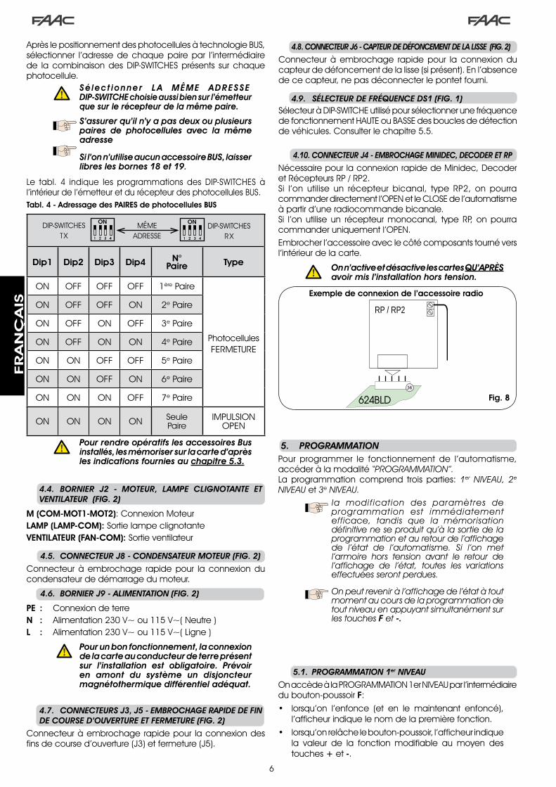
6
RP / RP2
624BLDJ4
4.4.. BORNIER. J2. -. MOTEUR,. LAMPE. CLIGNOTANTE. ET..VENTILATEUR..(FIG..2)
M (COM-MOT1-MOT2): Connexion MoteurLAMP (LAMP-COM): Sortie lampe clignotanteVENTILATEUR (FAN-COM): Sortie ventilateur
4.6.. BORNIER.J9.-.ALIMENTATION.(FIG..2)
PE : Connexion de terreN : Alimentation ��0 V~ ou ��5 V~( Neutre )L : Alimentation ��0 V~ ou ��5 V~( Ligne )
. . Pour.un.bon.fonctionnement,.la.connexion.de.la.carte.au.conducteur.de.terre.présent.sur. l’installation. est. obligatoire.. Prévoir.en. amont. du. système. un. disjoncteur.magnétothermique.différentiel.adéquat.
4.5.. CONNECTEUR.J8.-.CONDENSATEUR.MOTEUR.(FIG..2)
Connecteur à embrochage rapide pour la connexion du condensateur de démarrage du moteur.
4.7.. CONNECTEURS.J3,.J5.-.EMBROCHAGE.RAPIDE.DE.FIN.DE.COURSE.D’OUVERTURE.ET.FERMETURE.(FIG..2)
Connecteur à embrochage rapide pour la connexion des fins de course d’ouverture (J�) et fermeture (J5).
Après le positionnement des photocellules à technologie BUS, sélectionner l’adresse de chaque paire par l’intermédiaire de la combinaison des DIP-SWITCHES présents sur chaque photocellule.
.. Sé lec t ionner . LA . MÊME . ADRESSE. .DIP-SWITCHE.choisie.aussi.bien.sur.l’émetteur.que.sur.le.récepteur.de.la.même.paire.
..S’assurer.qu’il.n’y.a.pas.deux.ou.plusieurs.paires. de. photocellules. avec. la. même.adresse
. . Si.l’on.n’utilise.aucun.accessoire.BUS,.laisser.libres.les.bornes.18.et.19.
Le tabl. 4 indique les programmations des DIP-SWITCHES à l’intérieur de l’émetteur et du récepteur des photocellules BUS.Tabl. 4 - Adressage des PAIRES de photocellules BUS
Dip1 Dip2 Dip3 Dip4 N° Paire Type
ON OFF OFF OFF �ère Paire
Photocellules FERMETURE
ON OFF OFF ON �e Paire
ON OFF ON OFF �e Paire
ON OFF ON ON 4e Paire
ON ON OFF OFF 5e Paire
ON ON OFF ON 6e Paire
ON ON ON OFF 7e Paire
ON ON ON ON Seule Paire
IMPULSION OPEN
DIP-SWITCHESTX
DIP-SWITCHESRX
MÊME ADRESSE
. Pour.rendre.opératifs.les.accessoires.Bus.installés,.les.mémoriser.sur.la.carte.d’après.les.indications.fournies.au.chapitre.5.3.
4.10..CONNECTEUR.J4.-.EMBROCHAGE.MINIDEC,.DECODER.ET.RP
Nécessaire pour la connexion rapide de Minidec, Decoder et Récepteurs RP / RP�.Si l’on utilise un récepteur bicanal, type RP�, on pourra commander directement l’OPEN et le CLOSE de l’automatisme à partir d’une radiocommande bicanale.Si l’on utilise un récepteur monocanal, type RP, on pourra commander uniquement l’OPEN.Embrocher l’accessoire avec le côté composants tourné vers l’intérieur de la carte.
. On.n’active.et.désactive.les.cartes.QU’APRèS.avoir.mis.l’installation.hors.tension.
4.8..CONNECTEUR.J6.-.CAPTEUR.DE.DÉFONCEMENT.DE.LA.LISSE..(FIG..2)
Connecteur à embrochage rapide pour la connexion du capteur de défoncement de la lisse (si présent). En l’absence de ce capteur, ne pas déconnecter le pontet fourni.
4.9.. SÉLECTEUR.DE.FRÉQUENCE.DS1.(FIG..1)Sélecteur à DIP-SWITCHE utilisé pour sélectionner une fréquence de fonctionnement HAUTE ou BASSE des boucles de détection de véhicules. Consulter le chapitre 5.5.
la modification des paramètres deprogrammation est immédiatementefficace, tandis que la mémorisationdéfinitiveneseproduitqu’àlasortiedelaprogrammationetauretourdel’affichagede l’état de l’automatisme. Si l’on metl’armoire hors tension avant le retour del’affichage de l’état, toutes les variationseffectuéesserontperdues.
Onpeutreveniràl’affichagedel’étatàtoutmomentaucoursdelaprogrammationdetoutniveauenappuyantsimultanémentsurlestouchesFet-.
.5.. PROGRAMMATIONPour programmer le fonctionnement de l’automatisme, accéder à la modalité“PROGRAMMATION”.La programmation comprend trois parties: 1er NIVEAU, 2eNIVEAUet3eNIVEAU.
5.1.. PROGRAMMATION.1er.NIVEAU
On accède à la PROGRAMMATION �er NIVEAU par l’intermédiaire du bouton-poussoir F:
• lorsqu’on l’enfonce (et en le maintenant enfoncé), l’afficheur indique le nom de la première fonction.
• lorsqu’on relâche le bouton-poussoir, l’afficheur indique la valeur de la fonction modifiable au moyen des touches + et -.
Exemple de connexion de l’accessoire radio
Fig. 8
FRA
NÇ
AIS

7
• lorsqu’on enfonce de nouveau le bouton-poussoir F (et en le maintenant enfoncé), l’afficheur indique le nom de la fonction suivante, etc.
• arrivés à la dernière fonction, en appuyant sur le bouton-poussoir F, on sort de la programmation et l’afficheur affiche de nouveau l’état des entrées.
PROGRAMMATION 1er NIVEAU
Afficheur Fonction Par défaut
dFCHARGEMENT DES PARAMÈTRES:
00 Condition neutre0 1 Par défaut FAAC � chargé02 Par défaut RÉSERVÉ FAAC03 Par défaut FAAC CITY chargé04 Par défaut FAAC CITY K chargé05 Par défaut J�75 chargé06 Par défaut J�75K chargé
LAISSER À 00 SI L’ON NE SOUHAITE EFFECTUER AUCUNE MODIFICATION DE LA PROGRAMMATION.Pour l’explication du paramètre dF voir page.8.chapitre.5.2.
00
buMENU ACCESSOIRES BUSPour l’explication de ce paramètre voir page.8.chapitre.5.3.
LOLOGIQUES DE FONCTIONNEMENT:
A AutomatiqueA 1 Automatique �E Semi-automatiqueP ParkingPA Parking automatiqueCn CopropriétéCA Copropriété automatiquerb Faac-City (pour borne escamotable)C Homme mortr RemoteCu Custom
E
PATEMPS DE PAUSE:
N’a d’effet que si l’on a sélectionné une logique automatique. Réglable de 0 à 59 s en pas d’� seconde.Ensuite, l’affichage change en minutes et en dizaines de secondes (séparées par un point) et on règle le temps en pas de �0 secondes, jusqu’à la valeur maximum de 4 . 1 minutes.EX: si l’afficheur indique 2.5, le temps de pause correspond à � min. et 50 s.
20
FOFORCE:Règle la poussée du moteur. 0 1 = force minimum 50 = force maximum
50
L 1LOOP 1:En activant cette fonction, le loop connecté à l’entrée Loop� aura la fonction d’OPEN. Y = loop� actif n o = loop� pas actifAttention: si l’on active la fonction, l’état du Loop� sera quoi qu’il en soit disponible sur une des sorties opportunément sélectionnée (voir programmation de second niveau).
no
Afficheur Fonction Par défaut
L2 LOOP 2:En activant cette fonction, le loop connecté à l’entrée Loop� aura la fonction de SAFETY / CLOSE, c’est-à-dire qu’il fonctionnera comme SAFETY durant la phase de fermeture et au désengagement il commandera le CLOSE à la carte. Y = loop� actif n o = loop� pas actifAttention: si l’on n’active pas la fonction, l’état du Loop� sera quoi qu’il en soit disponible sur une des sorties opportunément sélectionnée.
no
H1 FONCTION BOOST LOOP 1
Y = Active no = ExclueCette fonction permet d’augmenter le niveau de sensibilité au moment de la détection. Quand un véhicule s’éloigne de la boucle, la sensibilité revient au niveau sélectionné. Ce système permet de maintenir le contact de détection également dans le cas de camions très hauts ou durant le passage éventuel d’une motrice avec une remorque.
no
H2 FONCTION BOOST LOOP 2
Y = Active no = ExclueVoir fonction BOOST LOOP�.
no
S 1 SENSIBILITÉ LOOP 1Règle la sensibilité de la boucle: 0 1 = minimum 1 0 = maximum
05
S2 SENSIBILITÉ LOOP 2Règle la sensibilité de la boucle: 0 1 = minimum 1 0 = maximum
05
StÉTAT DE L’AUTOMATISME:Sortie de la programmation,mémorisation des données sélectionnées et re-tour à l’affichage de l’état de l’automatisme.
00 Fermé
0 1 Préclignotement ouverture
02 Ouverture
03 Ouvert
04 En pause
05 Préclignotement fermeture
06 Fermeture
07 Immobile prêt à fermer
08 Immobile prêt à ouvrir
09 Ouverture d’urgence
10 Intervention sécurité fermeture
L’affichage de l’état de l’automatisme St estfondamentalpourletechnicieninstallateur/préposéàl’entretienafindedistinguerlesprocessuslogiquesque la carte effectue durant les manutentions.Si,parexemple,l’automatismesetrouveenétatdeFERMÉl’afficheurDOITindiquer00.Àl’arrivéedelacommandeOPEN,l’afficheuraffichera0 1 ,silepréclignotementestvalidé,oudirectement02 (le mouvement d’OUVERTURE) puisaffichera 03 lorsque la position de passageOUVERTseraatteinte.
FRA
NÇ
AIS
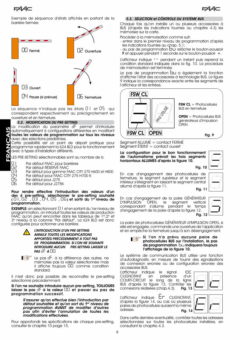
8
Exemple de séquence d’états affichés en partant de la barrière fermée:
La séquence n’indique pas les états 0 1 et 05 qui correspondent respectivement au préclignotement en ouverture et en fermeture.
00 Fermé 02 Ouverture
04 Pause (si prévue)
03 Ouvert
06 Fermeture
5.2.. MODIFICATION.DU.PRE-SETTINGLa modification du paramètre dF permet d’introduire automatiquement 6 configurations différentes en modifiant toutes les valeurs de programmation sur tous les niveaux avec des sélections prédéfinies.Cette possibilité est un point de départ pratique pour programmer rapidement la 6�4 BLD pour le fonctionnement avec 6 types d’installation différents.
LES PRE-SETTING sélectionnables sont au nombre de 6:
0 1 Par défaut FAAC pour barrières 02 Par défaut RÉSERVÉ FAAC03 Par défaut pour gamme FAAC CITY �75 H600 et H80004 Par défaut pour FAAC CITY �75 H700 K05 Par défaut pour J�7506 Par défaut pour J�75K
Pour rendre effective l’introduction des valeurs d’un des 6 pre-setting, sélectionner le pre-setting souhaité ( 0 1 , 02 , 03 , 04 , 05 , 06 ) et sortir du 1er niveau de programmation.EXEMPLE: en sélectionnant 0 1 et en sortant du �er niveau de programmation, on introduit toutes les valeurs de production FAAC qu’on peut rencontrer dans les tableaux de �er,�e et �e niveau à la colonne “Par défaut”. La 6�4 BLD est donc configurée pour actionner une barrière.
. L’INTRODUCTION.D’UN.PRE-SETTING..ANNULE.TOUTES.LES.MODIFICATIONS.APPORTÉES.PRÉCÉDEMMENT.à.TOUT.PAS.DE..PROGRAMMATION..SI.L’ON.NE.SOUHAITE.INTRODUIRE.AUCUN. .PRE-SETTING.LAISSER.LE.PAS.dF .à.00.
Le pas dF, à la différence des autres, ne mémorise pas la valeur sélectionnée mais il affiche toujours 00 comme condition standard.
Il n’est donc pas possible de reconnaître le pre-setting sélectionné précédemment.Si l’on ne souhaite introduire aucun pre-setting, TOUJOURS laisser le pas dF à la valeur 00 et passer au pas de programmation successif.
S’assurer.qu’on.effectue.bien.l’introduction.par.défaut.souhaitée.et.qu’on.sort.du.1er.niveau.de.programmation. AVANT. de. modifier. d’autres.pas. afin. d’éviter. l’annulation. de. toutes. les.modifications.effectuées.
Pour approfondir les spécifications de chaque pre-setting, consulter le chapitre �0 page �5.
5.3.. SÉLECTION.et.CÔNTROLE.DU.SYSTèME.BUSChaque fois qu’on installe un ou plusieurs accessoires à BUS (d’après les indications fournies au chapitre 4.�) les mémoriser sur la carte.Procéder à la mémorisation comme suit:- entrer dans le premier niveau de programmation d’après
les indications fournies au chap. 5.�;- au pas de programmation bu relâcher le bouton-poussoir
F et appuyer pendant � seconde sur le bouton-poussoir +.
L’afficheur indique -- pendant un instant puis reprend la condition standard indiquée dans la fig. �0. La procédure de mémorisation est terminée.Le pas de programmation bu a également la fonction d’afficher l’état des accessoires à technologie BUS. La figure 9 indique la correspondance exacte entre les segments de l’afficheur et les entrées.
Fig. 9
Segment ALLUMÉ = contact FERMÉSegment ÉTEINT = contact ouvert
FSW CL = Photocellules BUS en fermeture
OPEN = Photocellules BUS générateurs d’impulsion OPEN
PAS
UTILI
SÉ
La configuration pour le bon fonctionnement de l’automatisme prévoit les trois segments horizontaux ALLUMÉS d’après la figure 10.
En cas d’engagement des photocellules de fermeture, le segment supérieur et le segment inférieur s’éteignent en laissant le segment central allumé d’après la figure ��.
En cas d’engagement de la paire GÉNÉRATEUR D’IMPULSION OPEN, le segment vertical correspondant s’allume pendant le temps d’engagement de la paire d’après la figure ��.
Fig. 10
Fig. 11
Fig. 12
La paire de photocellules GÉNÉRATEUR d’IMPULSION OPEN, si elle est engagée, commande une ouverture de l’application et en empêche la fermeture jusqu’à son désengagement.
Si l’on n’a prévu aucune paire de photocellules BUS sur l’installation, le pas de programmation bu indiquera toujours l’affichage de la figure 10.
Le système de communication BUS utilise une fonction d’autodiagnostic en mesure de fournir des signalisations de connexion erronée ou de configuration erronée des accessoires BUS.L’afficheur indique le signal cc CLIGNOTANT en présence d’un COURT-CIRCUIT le long de la ligne BUS d’après la figure ��. Contrôler les connexions réalisées (chap.4.�).
L’afficheur indique Er CLIGNOTANT, d’après la figure �4, au cas où plusieurs paires de photocellules auraient la même adresse.
Fig. 13
Fig. 14
Dans cette dernière eventualité, contrôler toutes les adresses sélectionnées sur toutes les photocellules installées, en consultant le chapitre 4.�.
FRA
NÇ
AIS

9
PROGRAMMATION 2e NIVEAU
Afficheur FonctionPar
défaut
bo COUPLE MAXIMUM AU DÉMARRAGE:le moteur fonctionne au couple maximum (ignorant le réglage du couple) à l’instant initial du mouvement.
Y = Active no = Exclue
Y
PF PRÉCLIGNOTEMENT:permet d’activer la lampe clignotante pendant 5 s avant le début du mouvement.
no exclu
OC avant chaque mouvement
PA uniquement en fin pause
CL avant la fermeture
no
SC FERMETURE LENTE:permet de sélectionner toute la phase de fermeture à vitesse ralentie.
Y = Active no = Exclue
no
tr TEMPS RALENTISSEMENT EN FIN DE COURSE:permet de sélectionner le temps (en secondes) de ralentissement après l’intervention des fins de course d’ouverture et de fermeture.Réglable de 0 à 10 s en pas d’� seconde.
0 0 = ralentissement exclu 1 0 = ralentissement maximum
03
t TEMPS DE FONCTIONNEMENT (délai d’attente):Il est opportun de sélectionner une valeur de 5÷�0 secondes supérieure au temps nécessaire à l’automatisme pour passer de la position de fermeture à la position d’ouverture et vice versa.Réglable de 0 à 59 s en pas d’� seconde.Ensuite, l’affichage change en minutes et en dizaines de secondes (séparées par un point) et on règle le temps en pas de �0 secondes, jusqu’à la valeur maximum de 4.1 minutes.
20
FS FAIL SAFE:L’activation de la fonction valide un test de fonctionnement des photocellules avant chaque mouvement de l’automatisme, indépendamment de la sortie utilisée. Si le test échoue, l’automatisme ne commence pas le mouvement.
Y = Active no = Exclue
no
5.4.. PROGRAMMATION.2e.NIVEAU
Pour accéder à la PROGRAMMATION de �e NIVEAU appuyer sur le bouton-poussoir F et, en le maintenant enfoncé, appuyer sur le bouton-poussoir +:• lorsqu’on relâche le bouton-poussoir +, l’afficheur indique
le nom de la première fonction.• lorsqu’on relâche le bouton-poussoir F, l’afficheur indique
la valeur de la fonction modifiable au moyen des touches + et -.
• lorsqu’on enfonce la touche F (et en la maintenant enfon-cée), l’afficheur indique le nom de la fonction suivante; en la relâchant, il indique la valeur modifiable avec les touches + et -.
• arrivés à la dernière fonction, en appuyant sur le bouton-poussoir F, on sort de la programmation et l’afficheur affiche de nouveau l’état des entrées.
o 1 SORTIE 1:On peut sélectionner la sortie dans l’une des fonctions suivantes:
00 FAILSAFE
0 1 LAMPE TÉMOIN (allumée en ouverture et pause, clignotante en fermeture, éteinte lorsque l’automatisme est fermé).
02 ÉCLAIRAGE LISSE (sortie active lorsque la lisse est fermée et en pause, inactive lorsque la lisse est ouverte, intermittente en mouvement)
03 lisse FERMÉE
04 lisse OUVERTE ou en PAUSE, s’éteint durant le préclignotement en fermeture.
05 lisse en MOUVEMENT OUVERTURE, préclignotement compris.
06 lisse en MOUVEMENT FERMETURE, préclignotement compris.
07 lisse ARRÊTÉE
08 Lisse EN URGENCE
09 LOOP� engagé
10 LOOP� engagé
1 1 OPEN pour 6�4 SLAVE
12 CLOSE pour 6�4 SLAVE
13 lisse DÉCROCHÉE
14 lumières borne
15 vibreur sonore borne
16 FCA engagé
17 FCC engagé
18 interblocage
00
P 1 POLARITÉ SORTIE 1:Permet de configurer de la polarité de sortie. Y = polarité N.F. no = polarité N.O.
Remarque: si la sortie est sélectionnée comme FAIL-SAFE ( 00 ) laisser la valeur no .
no
o2 SORTIE 2:Voir sortie � 03
P2 POLARITÉ SORTIE 2:Voir polarité sortie � no
o3 SORTIE 3:Voir sortie � 0 1
P3 POLARITÉ SORTIE 3:Voir polarité sortie � no
o4 SORTIE 4 / BUS:Si la sélection correspond à 00 la sortie est dédiée aux accessoires à technologie BUS. Voir l’explication au Chapitre 4.3 page 5.Cette sortie ne modifie pas les possibilités de configuration de la sortie � à l’exception des fonctions 1 1 , 12 , 18 qui n’ont aucun effet dans ce cas.
00
P4 POLARITÉ SORTIE 4:Permet de configurer de la polarité de sortie. Y = polarité N.F. no = = polarité N.O. (pour BUS)
no
FRA
NÇ
AIS

�0
AS DEMANDE D’ASSISTANCE (associée aux deux fonctions successives):Si elle est activée, à la fin du compte à rebours (sélectionnable avec les deux fonctions successives “Programmation cycles“) active la sortie LAMP pendant une période de 4 s toutes les �0 s (demande d’intervention). Elle peut être utile pour sélectionner des interventions d’entretien programmé.
Y = Active no = Exclue
no
nc PROGRAMMATION CYCLES EN MILLIERS:Permet de sélectionner un compte à rebours des cycles de fonctionnement de l’installation, valeur sélectionnable de 0 à 99 (milliers de cycles). La valeur affichée se met à jour par la succession des cycles, en interagissant avec la valeur de nC (99 diminutions de nc correspondent à une diminution de nC).La fonction peut être utilisée, en association avec nC, pour vérifier l’utilisation de l’installation et pour bénéficier de la “Demande d’assistance“.
00
nC PROGRAMMATION CYCLES EN CENTAINES DE MILLIERS:Permet de sélectionner un compte à rebours des cycles de fonctionnement de l’installation, valeur sélectionnable de 0 à 99 (centaines de milliers de cycles). La valeur affichée se met à jour par la succession des cycles, en interagissant avec la valeur de nc . (� diminution de nC correspond à 99 diminutions de nc ).La fonction peut être utilisée, en association avec nc , pour vérifier l’utilisation de l’installation et pour bénéficier de la “Demande d’assistance“.
0 1
h 1 DURÉE D’OCCUPATION LOOP 1Permet de sélectionner le temps de présence sur le loop �. Au terme de ce temps, la carte s’auto-calibre et signale “boucle libre“ (point décimal des unités OFF). À la mise sous tension de la carte, une remise à zéro automatique est effectuée.
Y = 5 minutes no = infini
no
h2 DURÉE D’OCCUPATION LOOP 2Permet de sélectionner le temps de présence sur le loop �. Au terme de ce temps, la carte s’auto-calibre et signale “boucle libre“ (point décimal des dizaines OFF). À la mise sous tension de la carte, une remise à zéro automatique est effectuée. Y = 5 minutes no = infini
no
St ÉTAT DE L’AUTOMATISME:Sortie de la programmation, mémorisation des données et retour à l’affichage de l’état du portail (voir par. 5.�.).
5.5.. SÉLECTION.LOOP.DETECTOR.INTÉGRÉ
6�4 BLD est équipée d’un détecteur de métaux intégré pour la détection à induction de véhicules.Caractéristiques:
séparation galvanique entre l’électronique du détecteur et celle de la bouclealignement automatique du système immédiatement après l’activationremise à zéro continue des dérives de fréquencesensibilité indépendante de l’inductivité de la boucleréglage de la fréquence de fonctionnement des bouclesmessage de boucle occupée avec affichage à LEDsétat des boucles adressable sur les sorties OUT �, OUT �, OUT � et OUT 4
•
•
•••••
Point ALLUMÉ = Boucle ENGAGÉEPoint ÉTEINT = Boucle LIBREPoint CLIGNOT. = Boucle PAS CONNECTÉE ou EN ÉTALONNAGE
LOOP � LOOP �
RÉGLAGE DE LA SENSIBILITÉEn réglant la sensibilité, on détermine la variation de l’inductivité, pour chaque canal, qu’un véhicule doit provoquer pour activer la sortie correspondante du détecteur.Le réglage de la sensibilité est effectué séparément pour chaque canal à l’aide des deux paramètres S 1 et S2 au �er niveau de programmation. On peut également activer la fonction BOOST pour les deux détecteurs. Consulter le chapitre 5.�
RÉGLAGE DE LA DURÉE D’OCCUPATIONLe calcul de la durée d ’occupation commence à l’engagement de la boucle. Si à l’échéance de ce temps la boucle est encore engagée, un nouvel étalonnage automatique est effectué où la présence de métal sur la boucle n’en détermine plus l’engagement. Au terme du nouvel étalonnage la boucle est considérée comme “libre“. La durée d’occupation peut être réglée à l’aide des deux paramètres h 1 et h2 du �e niveau de programmation.Consulter le chapitre 5.4
Connexion:
Connecter les boucles de détection d’après la figure � page 4:
- Bornes � - � pour le LOOP � = boucle avec fonction d’ouverture du passage;
- Bornes � - 4 pour le LOOP � = boucle avec fonction de fermeture et/ou de sécurité en fermeture.
Pour approfondir l’effet sur l’automatisme des signaux en provenance des boucles, voir les tableaux des logiques au chapitre ��.
Pour valider la fonctionnalité des boucles connectées, entrer dans le 1er niveau de programmation et sélectionner les pas L1 et L2 en Y simultanément aux boucles connectées. En présence d’une seule boucle, valider uniquement le pas de programmation correspondant.L’état de fonctionnement du loop detector est indiqué par l’intermédiaire des points décimaux de l’afficheur quand s’affiche l’état de l’automatisme (pas St ).
ÉTALONNAGEChaque fois qu’on met la carte 6�4 BLD sous tension l’afficheur indique l’état de l’automatisme et le loop detector intégré effectue un auto-étalonnage des boucles connectées. Par conséquent, effectuer un étalonnage en mettant 6�4 BLD hors tension pendant au moins 5 secondes.
L’étalonnage est affiché par l’intermédiaire du clignotement des deux points d’après la figure �5.
. Si. une. seule.ou. les.deux.boucles.magnétiques.ne.sont.pas.installées,.le.loop.detector.reste.en.étalonnage.constant.sans.que.cela..provoque.des.problèmes.de.fonctionnement.de.la.carte..Ainsi,.durant.l’affichage.de.l’état.de.l’automatisme,.un.seul. ou. les. deux. points. décimaux. clignoteront.constamment.
Après l’étalonnage, les points décimaux représentent les états des boucles:
Fig. 15
FRA
NÇ
AIS
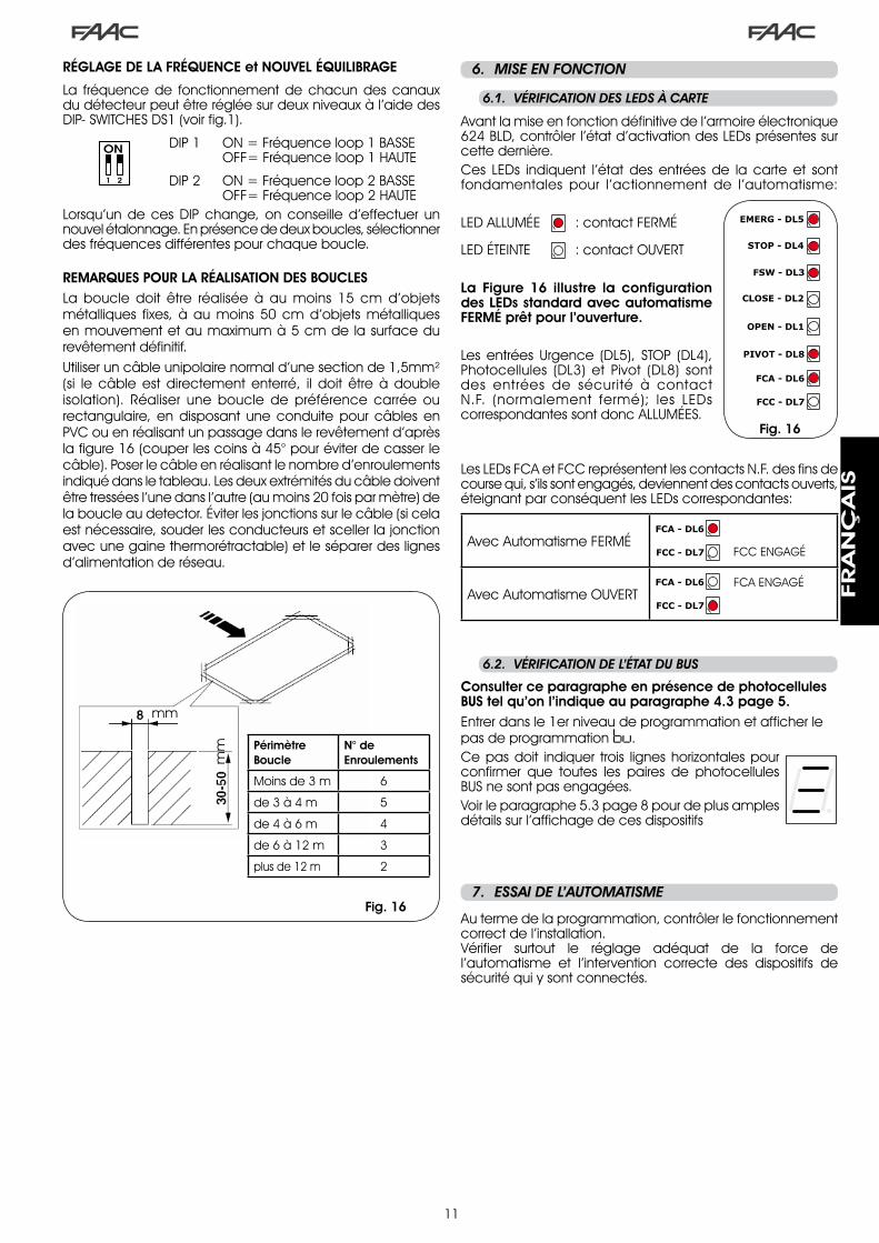
��
.6.. MISE.EN.FONCTION
6.1.. VÉRIFICATION.DES.LEDS.à.CARTE
Fig. 16
6.2.. VÉRIFICATION.DE.L’ÉTAT.DU.BUS
Consulter ce paragraphe en présence de photocellules BUS tel qu’on l’indique au paragraphe 4.3 page 5.Entrer dans le �er niveau de programmation et afficher le pas de programmation bu.Ce pas doit indiquer trois lignes horizontales pour confirmer que toutes les paires de photocellules BUS ne sont pas engagées.Voir le paragraphe 5.� page 8 pour de plus amples détails sur l’affichage de ces dispositifs
.7.. ESSAI.DE.L’AUTOMATISME
Au terme de la programmation, contrôler le fonctionnement correct de l’installation.Vérifier surtout le réglage adéquat de la force de l’automatisme et l’intervention correcte des dispositifs de sécurité qui y sont connectés.
RÉGLAGE DE LA FRÉQUENCE et NOUVEL ÉQUILIBRAGE
La fréquence de fonctionnement de chacun des canaux du détecteur peut être réglée sur deux niveaux à l’aide des DIP- SWITCHES DS� (voir fig.�).
DIP � ON = Fréquence loop � BASSE OFF= Fréquence loop � HAUTE
DIP � ON = Fréquence loop � BASSE OFF= Fréquence loop � HAUTELorsqu’un de ces DIP change, on conseille d’effectuer un nouvel étalonnage. En présence de deux boucles, sélectionner des fréquences différentes pour chaque boucle.
REMARQUES POUR LA RÉALISATION DES BOUCLESLa boucle doit être réalisée à au moins �5 cm d’objets métalliques fixes, à au moins 50 cm d’objets métalliques en mouvement et au maximum à 5 cm de la surface du revêtement définitif. Utiliser un câble unipolaire normal d’une section de �,5mm² (si le câble est directement enterré, il doit être à double isolation). Réaliser une boucle de préférence carrée ou rectangulaire, en disposant une conduite pour câbles en PVC ou en réalisant un passage dans le revêtement d’après la figure �6 (couper les coins à 45° pour éviter de casser le câble). Poser le câble en réalisant le nombre d’enroulements indiqué dans le tableau. Les deux extrémités du câble doivent être tressées l’une dans l’autre (au moins �0 fois par mètre) de la boucle au detector. Éviter les jonctions sur le câble (si cela est nécessaire, souder les conducteurs et sceller la jonction avec une gaine thermorétractable) et le séparer des lignes d’alimentation de réseau.
Avant la mise en fonction définitive de l’armoire électronique 6�4 BLD, contrôler l’état d’activation des LEDs présentes sur cette dernière.Ces LEDs indiquent l’état des entrées de la carte et sont fondamentales pour l’actionnement de l’automatisme:
LED ALLUMÉE : contact FERMÉ
LED ÉTEINTE : contact OUVERT
La Figure 16 illustre la configuration des LEDs standard avec automatisme FERMÉ prêt pour l’ouverture.
Les entrées Urgence (DL5), STOP (DL4), Photocellules (DL�) et Pivot (DL8) sont des entrées de sécurité à contact N.F. (normalement fermé); les LEDs correspondantes sont donc ALLUMÉES.
Les LEDs FCA et FCC représentent les contacts N.F. des fins de course qui, s’ils sont engagés, deviennent des contacts ouverts, éteignant par conséquent les LEDs correspondantes:
Avec Automatisme FERMÉFCC ENGAGÉ
Avec Automatisme OUVERTFCA ENGAGÉ
PérimètreBoucle
N° deEnroulements
Moins de � m 6
de � à 4 m 5
de 4 à 6 m 4
de 6 à �� m �
plus de �� m �
mm
mm
Fig. 16
FRA
NÇ
AIS

��
1 OFF2 OFF
Fig. 17
.8.. CONFIGURATIONS.MASTER-SLAVE
Si l’installation prévoit l’utilisation de deux barrières opposées à actionner simultanément en ouverture/fermeture du passage, utiliser un des diagrammes de connexion indiqués ci-après en fonction des cartes électroniques utilisées pour actionner les barrières.
On entend par armoire MASTER, la carte électronique à laquelle sont connectés tous les générateurs d’impulsion et les dispositifs de sécurité.On entend par armoire SLAVE, la carte électronique pilotée par l’armoire MASTER par l’intermédiaire des entrées d’impulsion tandis que les entrées de sécurité sont court-circuitées.
a PROGRAMMATION.1er.NIVEAU
LO = Cb .PROGRAMMATION.3e.NIVEAU
03 = Yc .PROGRAMMATION.1er.NIVEAU.
LO = CU
FRA
NÇ
AIS

��
La programmation de �e niveau est uniquement utilisée dans l’éventualité d’une personnalisation avancée des logiques de fonctionnement déjà en mémoire.
Avant.d’effectuer.des.modifications.à.ce.niveau,.s’assurer.qu’on.a.pleinement.compris.la.nature.des.pas.qu’on.veut.modifier.et.leur.influence.sur.l’automatisme.
Pour accéder à la PROGRAMMATION �e NIVEAU, appuyer sur le bouton-poussoir F et, en le maintenant enfoncé, appuyer sur le bouton-poussoir + pendant environ 10 secondes. Les touches F, + et – ont la même fonction que pour les deux autres niveaux de programmation.
PROGRAMMATION 3e NIVEAU 10 s
D. Fonction Sélection
0 1 En activant cette fonction, on obtient la fermeture automatique après le temps de pause.
Y = fermeture automatiqueno = désactive
02 En activant cette fonction, on obtient le fonctionnement à deux entrées distinctes: OPEN pour l’ouverture et CLOSE pour la fermeture.
Y = fonctionnement � entréesno = désactive
03Activation de la reconnaissance des niveaux des entrées OPEN et CLOSE (commande maintenue). Cela signifie que la carte reconnaît le niveau (par exemple avec OPEN maintenue et on appuie sur le STO; au relâchement de ce dernier l’automatisme continue à ouvrir). Si 0� est désactivé, la carte commande une manœuvre uniquement en cas de variation de l’entrée.
Y = reconnaissance niveauno = reconnaissance à la
variation de l’état
04 Activation de l’ouverture HOMME MORT (commande toujours enfoncée). En relâchant la commande OPEN, on bloque le fonctionnement
Y = activeno = désactive
05En activant cette fonction, la commande d’OPEN durant l’ouverture arrête le mouvement.Si le paramètre 06 est no le système est prêt pour l’ouverture.Si le paramètre 06 est Y le système est prêt pour la fermeture.
Y = bloque en ouvertureno = désactive
06 En activant cette fonction, la commande d’OPEN durant l’ouverture inverse le mouvement.Si les paramètres 05 et 06 sont no l’OPEN n’a aucun effet durant l’ouverture.
Y = inverse en ouvertureno = désactive
07En activant cette fonction, la commande d’OPEN durant la pause bloque le fonctionnement.Si les paramètres 07 et 08 sont no l’OPEN recharge le temps de pause.
Y = bloque en pauseno = désactive
08 En activant cette fonction, la commande d’OPEN durant la pause provoque la fermeture. Si les paramètres 07 et 08 sont no l’OPEN recharge le temps de pause.
Y = ferme en pauseno = désactive
09 En activant cette fonction, la commande d’OPEN durant la fermeture bloque le fonctionnement; dans le cas contraire, elle inverse le mouvement.
Y = bloqueno = inverse
10 Activation de la fermeture HOMME MORT (commande toujours enfoncée). En relâchant la commande CLOSE, on bloque le fonctionnement.
Y = activeno = désactive
1 1 En activant cette fonction, la commande CLOSE a la priorité sur OPEN; dans le cas contraire, OPEN a la priorité sur CLOSE.
Y = activeno = désactive
12 En activant cette fonction, la commande CLOSE commande la fermeture à son relâchement. Tant que CLOSE est actif, l’unité reste en préclignotement fermeture.
Y = ferme au relâchementno = ferme immédiatement
13En activant cette fonction, la commande CLOSE durant l’ouverture bloque le fonctionnement, dans le cas contraire la commande CLOSE commande l’inversion immédiatement ou au terme de l’ouverture (voir aussi le paramètre 14)
Y = CLOSE bloqueno = CLOSE inverse
14 En activant cette fonction et si le paramètre 13 est no, la commande CLOSE commande la fermeture immédiate au terme du cycle d’ouverture (elle mémorise le CLOSE). Si les paramètres 13 et 14 sont no CLOSE commande la fermeture immédiate.
Y = ferme à la fin de l’ouverture
no = fermeture immédiate
15 En activant cette fonction avec le système bloqué par un STOP, un OPEN successif actionne dans la direction opposée. Si le paramètre 15 est no elle ferme toujours.
Y = actionne dans la direction opposée
no = ferme toujours
16En activant cette fonction, durant la fermeture, les SÉCURITÉS FERMETURE bloquent et permettent la reprise du mouvement à leur désengagement, dans le cas contraire, elles inversent immédiatement en ouverture
Y = ferme au désengagementno = inversion immédiate
17En activant cette fonction les SÉCURITÉS FERMETURE commandent la fermeture à leur désengagement.(voir aussi le paramètre 18).
Y = fermeture au désengagement du FSW
no = désactive
18 En activant cette fonction et si le paramètre 17 est Y, l’unité attend la fin du cycle d’ouverture avant d’exécuter la commande de fermeture fournie par les SÉCURITÉS FERMETURE.
Y = ferme à la fin de l’ouverture
no = désactive
19En activant cette fonction, durant la fermeture, LOOP 2 bloque et permet la reprise du mouvement au désengagement; dans le cas contraire, elle inverse immédiatement en ouverture.
Y = fermeture au désengagement
no = inversion immédiate
20 En activant cette fonction, LOOP 2 commande la fermeture à son désengagement (voir également paramètre 21).
Y = ferme si LOOP� est libreno = désactive
2 1 En activant cette fonction et si le paramètre 20 est Y , l’unité attend la fin du cycle d’ouverture avant d’exécuter la commande de fermeture fournie par LOOP 2.
Y = ferme en fin d’ouverture
no = désactive
22 En activant cette fonction, les commandes de LOOP� sont prioritaires sur les commandes de LOOP�.
Y = activeno = désactive
.9.. PROGRAMMATION.DE.3e..NIVEAU
FRA
NÇ
AIS
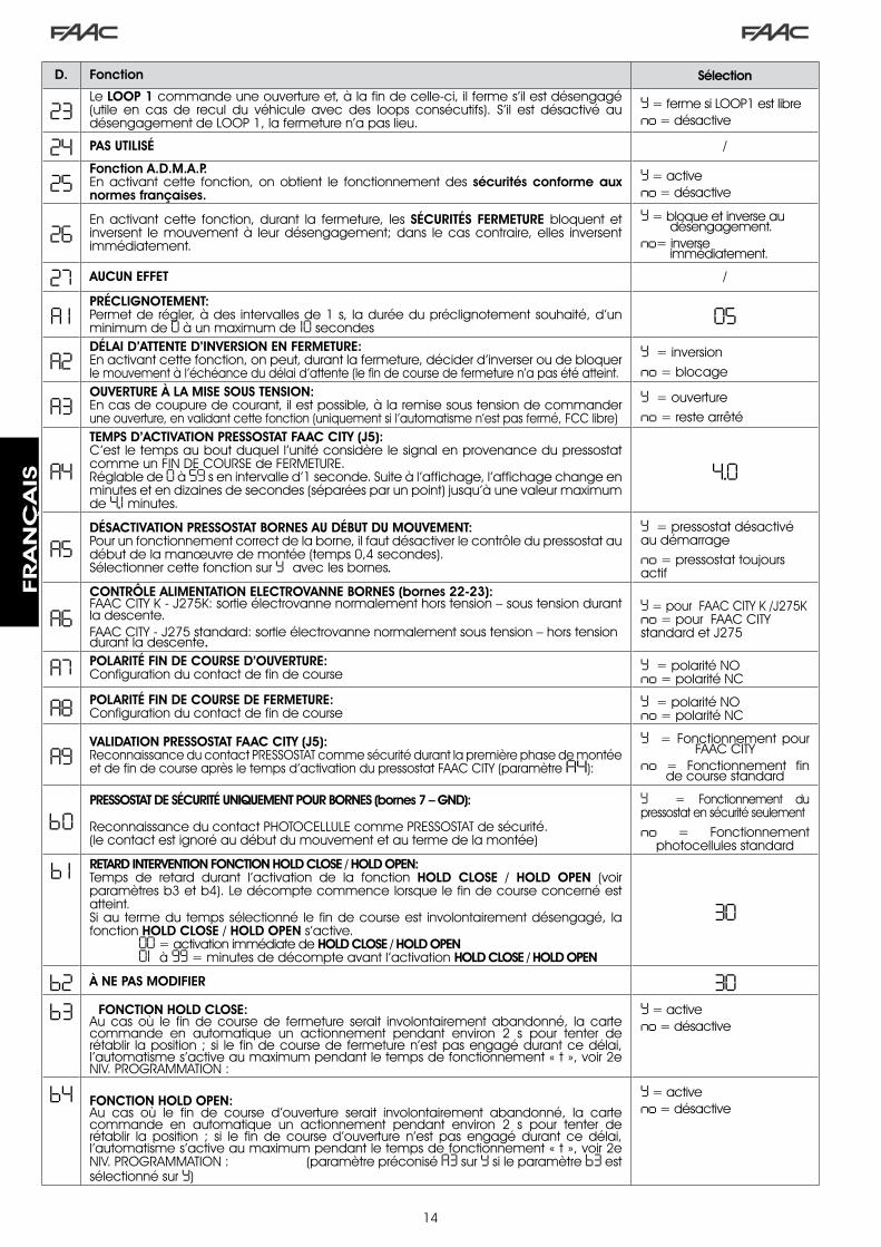
�4
D. Fonction Sélection
23Le LOOP 1 commande une ouverture et, à la fin de celle-ci, il ferme s’il est désengagé (utile en cas de recul du véhicule avec des loops consécutifs). S’il est désactivé au désengagement de LOOP �, la fermeture n’a pas lieu.
Y = ferme si LOOP� est libreno = désactive
24 PAS UTILISÉ /
25Fonction A.D.M.A.P.En activant cette fonction, on obtient le fonctionnement des sécurités conforme aux normes françaises.
Y = activeno = désactive
26En activant cette fonction, durant la fermeture, les SÉCURITÉS FERMETURE bloquent et inversent le mouvement à leur désengagement; dans le cas contraire, elles inversent immédiatement.
Y = bloque et inverse au désengagement.
no= inverse immédiatement.
27 AUCUN EFFET /
A 1PRÉCLIGNOTEMENT:Permet de régler, à des intervalles de � s, la durée du préclignotement souhaité, d’un minimum de 0 à un maximum de 10 secondes
05
A2DÉLAI D’ATTENTE D’INVERSION EN FERMETURE:En activant cette fonction, on peut, durant la fermeture, décider d’inverser ou de bloquer le mouvement à l’échéance du délai d’attente (le fin de course de fermeture n’a pas été atteint.
Y = inversionno = blocage
A3OUVERTURE À LA MISE SOUS TENSION:En cas de coupure de courant, il est possible, à la remise sous tension de commander une ouverture, en validant cette fonction (uniquement si l’automatisme n’est pas fermé, FCC libre)
Y = ouvertureno = reste arrêté
A4TEMPS D’ACTIVATION PRESSOSTAT FAAC CITY (J5):C’est le temps au bout duquel l’unité considère le signal en provenance du pressostat comme un FIN DE COURSE de FERMETURE.Réglable de 0 à 59 s en intervalle d’� seconde. Suite à l’affichage, l’affichage change en minutes et en dizaines de secondes (séparées par un point) jusqu’à une valeur maximum de 4,1 minutes.
4.0
A5DÉSACTIVATION PRESSOSTAT BORNES AU DÉBUT DU MOUVEMENT: Pour un fonctionnement correct de la borne, il faut désactiver le contrôle du pressostat au début de la manœuvre de montée (temps 0,4 secondes).Sélectionner cette fonction sur Y avec les bornes.
Y = pressostat désactivé au démarrage no = pressostat toujours actif
A6CONTRÔLE ALIMENTATION ELECTROVANNE BORNES (bornes 22-23):FAAC CITY K - J�75K: sortie électrovanne normalement hors tension – sous tension durant la descente.FAAC CITY - J�75 standard: sortie électrovanne normalement sous tension – hors tension durant la descente.
Y = pour FAAC CITY K /J�75K no = pour FAAC CITY standard et J�75
A7 POLARITÉ FIN DE COURSE D’OUVERTURE:Configuration du contact de fin de course
Y = polarité NOno = polarité NC
A8 POLARITÉ FIN DE COURSE DE FERMETURE:Configuration du contact de fin de course
Y = polarité NOno = polarité NC
A9VALIDATION PRESSOSTAT FAAC CITY (J5):Reconnaissance du contact PRESSOSTAT comme sécurité durant la première phase de montée et de fin de course après le temps d’activation du pressostat FAAC CITY (paramètre A4):
Y = Fonctionnement pour FAAC CITY
no = Fonctionnement fin de course standard
b0PRESSOSTAT DE SÉCURITÉ UNIQUEMENT POUR BORNES (bornes 7 – GND):
Reconnaissance du contact PHOTOCELLULE comme PRESSOSTAT de sécurité.(le contact est ignoré au début du mouvement et au terme de la montée)
Y = Fonctionnement du pressostat en sécurité seulementno = Fonctionnement
photocellules standard
b 1 RETARD INTERVENTION FONCTION HOLD CLOSE / HOLD OPEN: Temps de retard durant l’activation de la fonction HOLD CLOSE / HOLD OPEN (voir paramètres b� et b4). Le décompte commence lorsque le fin de course concerné est atteint.Si au terme du temps sélectionné le fin de course est involontairement désengagé, la fonction HOLD CLOSE / HOLD OPEN s’active. 00 = activation immédiate de HOLD CLOSE / HOLD OPEN 01 à 99 = minutes de décompte avant l’activation HOLD CLOSE / HOLD OPEN
30
b2 À NE PAS MODIFIER 30b3 FONCTION HOLD CLOSE:
Au cas où le fin de course de fermeture serait involontairement abandonné, la carte commande en automatique un actionnement pendant environ � s pour tenter de rétablir la position ; si le fin de course de fermeture n’est pas engagé durant ce délai, l’automatisme s’active au maximum pendant le temps de fonctionnement « t », voir �e NIV. PROGRAMMATION :
Y = activeno = désactive
b4 FONCTION HOLD OPEN:Au cas où le fin de course d’ouverture serait involontairement abandonné, la carte commande en automatique un actionnement pendant environ � s pour tenter de rétablir la position ; si le fin de course d’ouverture n’est pas engagé durant ce délai, l’automatisme s’active au maximum pendant le temps de fonctionnement « t », voir �e NIV. PROGRAMMATION : (paramètre préconisé A3 sur Y si le paramètre b3 est sélectionné sur Y)
Y = activeno = désactive
FRA
NÇ
AIS

�5
Par défaut FAAC1
RÉSERVÉ FAAC
Par défaut FAAC CITY
Par défaut FAAC CITY K
Par défaut J275
Par défaut J275K
9.1.. PERSONNALISATION.DE.LA.LOGIQUE.DE.FONCTIONNEMENT
Les valeurs de programmation du �e niveau varient en fonction de la logique sélectionnée au premier niveau de programmation.
Le �e niveau de programmation est dédié à la personnalisation d’une des logiques sélectionnables si l’on a besoin d’un comportement non standard de l’application.
Pour rendre effective la modification d’un ou plusieurs paramètres du �e niveau de programmation qui personnalisent le fonctionnement de la logique sélectionnée, procéder comme suit:
Sélectionner une des logiques de base qui s’adapte le mieux aux exigences personnelles.Entrer dans le �e niveau de programmation et modifier les paramètres souhaités.Sortir du �e niveau et du �er niveau et sélectionner la logique Cu.
La logique Cu rend actives les modifications apportées au �e niveau.
Le tableau suivant indique les paramètres par défaut qui concernent les logiques de fonctionnement.
�.
�.
�.
Pas A A1 E P PA Cn CA rb C
0 1 Y Y N N Y N Y Y N02 N N N Y Y Y Y Y Y03 N N N N N N N Y N04 N N N N N N N N Y05 N N Y N N N N N N06 N N Y N N N N N N07 N N N N N N N N N08 N N N N N N N N N09 N N N N N N N N N10 N N N N N N N N Y1 1 N N N N N N N N N12 N N N Y Y N N N N13 N N N N N N N N N14 N N N Y Y Y Y N N15 N N N N N N N N N16 N N N Y Y N N N N17 N Y N N N N N N N18 N Y N N N N N N N19 N N N Y Y N N N N20 N Y N Y Y Y Y N N2 1 N Y N Y Y Y Y N N22 N N N N N Y Y N N23 N N N Y Y N N N N24 N N N N N N N N N25 N N N N N N N N N26 N N N N N N N N N
.10.. VALEURS.DES.PRE-SETTING
Le tableau ci-après indique les valeurs des pas de chaque niveau de programmation par rapport au pre-setting choisi
1er NIVEAU
2e NIVEAU
b5 GESTION ÉLECTROVANNES BORNES:Fonction à sélectionner sur Y pour J�75 /J�75KFonction à sélectionner sur no pour FAAC CITY / FAAC CITY K.
Y = pour J�75 / J�75Kno= FAAC CITY / FAAC CITY K
b6 LOGIQUE DE FONCTIONNEMENT ENTRÉE URGENCE:Lorsqu’on active cette fonction, l’entrée d’urgence commande une fermeture qui est maintenue jusqu’au rétablissement du contact.Si cette fonction est désactivée, l’entrée d’urgence commande une ouverture qui est maintenue jusqu’au rétablissement du contact.
Y = activeno = désactivée
St ÉTAT DE L’AUTOMATISME:Sortie de la programmation, mémorisation des données et affichage de l’état du portail (voir par. 5.�.).
D. Fonction Sélection
Par défaut FAAC1
RÉSERVÉ FAAC
Par défaut FAAC CITY
Par défaut FAAC CITY K
Par défaut J275
Par défaut J275K
dF pre-setting 0 1 02 03 04 05 06bu BUS
Lo logique E A1 rb rb rb rbPA pause 20 20 30 30 30 30FO force 50 50 50 50 50 50L 1 loop � no no no no no noL2 loop � no no no no no noH 1 loop � no no no no no noH 2 loop � no no no no no noS 1 sensibilité 05 05 05 05 05 05S2 sensibilité 05 05 05 05 05 05
bo boost Y Y Y Y Y YPF préclignotement no CL no no no noSC fermeture lente no no no no no notr ralentissement 03 03 0 1 0 1 0 1 0 1t délai d’attente 20 20 12 12 12 12FS fail safe no no no no no noo 1 sortie � 00 16 15 15 15 15P 1 polarité � no no no no no noo2 sortie � 03 17 14 14 03 03P2 polarité � no no no no no noo3 sortie � 0 1 0 1 0 1 0 1 0 2 0 2P3 polarité � no no no no no noo4 sortie 4 00 00 00 00 00 00P4 polarité 4 no no no no no noA5 assistance no no no no no nonc cycles �. 00 00 00 00 00 00nC cycles �. 0 1 0 1 0 1 0 1 0 1 0 1h 1 occupation no no no no no noh2 occupation no no no no no no
FRA
NÇ
AIS
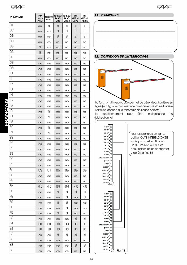
�6
____________________________________________________
_____________________________________________________
________________________________________________________________________________________________________
1918
1617
1514
1213
1011
89
67
45
23
1
OPEN A
STOP
LOOP 1
LOOP 2
LOOP 2
LOOP 1
CLOSE
FSW
EMERGENCY
OUT 1
OUT 2
OUT 4
OUT 3
GND
GND
GND
+24 V
+24 V
OUT 3
J119
1816
1715
1412
1310
118
96
74
52
31
OPEN A
STOP
LOOP 1
LOOP 2
LOOP 2
LOOP 1
CLOSE
FSW
EMERGENCY
OUT 1
OUT 2
OUT 4
OUT 3
GND
GND
GND
+24 V
+24 V
OUT 3
J119
1816
1715
1412
1310
118
96
74
52
31
OPEN A
STOP
LOOP 1
LOOP 2
LOOP 2
LOOP 1
CLOSE
FSW
EMERGENCY
OUT 1
OUT 2
OUT 4
OUT 3
GND
GND
GND
+24 V
+24 V
OUT 3
J1
.11.. REMARQUES
.12.. CONNEXION.DE.L’INTERBLOCAGE
La fonction d’interblocage permet de gérer deux barrières en ligne (voir fig.) de manière à ce que l’ouverture d’une barrière soit subordonnée à la fermeture de l’autre barrière.Le fonctionnement peut être unidirectionnel ou bidirectionnel.
Fig. 18
0 1 no Y Y Y Y Y02 no no Y Y Y Y03 no no Y Y Y Y04 no no no no no no05 Y no no no no no06 Y no no no no no07 no no no no no no
Par défaut FAAC1
RÉSERVÉ FAAC
Par défaut FAAC CITY
Par défaut FAAC CITY K
Par défaut J275
Par défaut J275K
08 no no no no no no09 no no no no no no10 no no no no no no1 1 no no no no no no12 no no no no no no13 no no no no no no14 no no no no no no15 no no no no no no16 no no no no no no17 no Y no no no no18 no Y no no no no19 no no no no no no20 no Y no no no no2 1 no Y no no no no22 no no no no no no23 no no no no no no24 no no no no no no25 no no no no no no26 no no no no no no27 no no no no no noA 1 05 0 1 05 05 05 05A2 no no no no no noA3 no no no no no noA4 4 .0 4 .0 04 04 4 .0 4 .0A5 no no Y Y Y YA6 no no no Y no YA7 no no Y Y no noA8 no no no Y no noA9 no no Y Y no nob0 no no no no Y Yb 1 00 00 30 30 30 30b2 30 30 30 30 30 30b3 no no Y Y Y Yb4 no no no no no nob5 no no no no Y Yb6 no no no no no no
3e NIVEAU
Pour les barrières en ligne, activer OUT� INTERBLOCAGE sur le paramètre �8 (voir PROG. �e NIVEAU) sur les deux cartes et les connecter d’après la fig. �8
FRA
NÇ
AIS

�7
Tab. 1/b
Tab. 1/a
LOGIQUE “A” IMPULSIONS
ÉTAT AUTOMATISME OPEN A CLOSE STOP FSW LOOP 1 LOOP 2
FERMÉouvre et referme
après le temps de pause
aucun effetaucun effet (ouverture inhibée)
aucun effetouvre et referme
après le temps de pause
aucun effet
EN OUVERTURE aucun effetinverse
immédiatement en fermeture
bloque lefonctionnement aucun effet aucun effet aucun effet
OUVERT EN PAUSE recharge le temps de pause ferme bloque le
fonctionnement
recharge le temps de pause
(fermeture inhibée)
recharge le temps de pause
recharge le temps de pause
(fermeture inhibée)
EN FERMETUREinverse
immédiatement en ouverture
aucun effet bloque lefonctionnement
inverse immédiatement
en ouverture
inverse immédiatement
en ouverture
inverse immédiatement
en ouverture
BLOQUÉ ferme fermeaucun effet (ouverture et
fermeture inhibées)
aucun effet (fermeture inhibée)
ouvre et referme après le temps de
pause
aucun effet (fermeture inhibée)
LOGIQUE “A1” IMPULSIONS
ÉTAT AUTOMATISME OPEN A CLOSE STOP FSW LOOP 1 LOOP 2
FERMÉouvre et referme
après le temps de pause
aucun effetaucun effet (ouverture inhibée)
aucun effetouvre et referme
après le temps de pause
aucun effet
EN OUVERTURE aucun effetinverse
immédiatement en fermeture
bloque lefonctionnement
ferme immédiatement
au terme de l’ouverture
aucun effetferme
immédiatement au terme de l’ouverture
OUVERT EN PAUSE recharge le temps de pause ferme bloque le
fonctionnement ferme recharge le temps de pause ferme
EN FERMETUREinverse
immédiatement en ouverture
aucun effet bloque lefonctionnement
inverse immédiatement
en ouverture
inverse immédiatement
en ouverture, ferme en fin de
pause
inverse immédiatement
en ouverture, referme à la fin de l’ouverture
BLOQUÉ ferme fermeaucun effet (ouverture et
fermeture inhibées)
aucun effet (fermeture inhibée)
ouvre et referme après le temps de
pause
aucun effet (fermeture inhibée)
LOGIQUE “E” IMPULSIONS
ÉTAT AUTOMATISME OPEN A CLOSE STOP FSW LOOP 1 LOOP 2
FERMÉ ouvre aucun effetaucun effet (ouverture inhibée)
aucun effet ouvre aucun effet
EN OUVERTURE bloque lefonctionnement
inverse immédiatement
en fermeture
bloque lefonctionnement aucun effet aucun effet aucun effet
OUVERT ferme fermeaucun effet (fermeture inhibée)
aucun effet (fermeture inhibée)
fermeaucun effet (fermeture inhibée)
EN FERMETUREinverse
immédiatement en ouverture
aucun effet bloque lefonctionnement
inverse immédiatement
en ouverture
inverse immédiatement
en ouverture
inverse immédiatement
en ouverture
BLOQUÉ ferme fermeaucun effet (ouverture et
fermeture inhibées)
aucun effet (fermeture inhibée)
ouvreaucun effet (fermeture inhibée)
Entre parenthèses, les effets sur les autres entrées à impulsion active
.13.. TABLEAUX.DES.LOGIQUES.DE.FONCTIONNEMENT
Tab. 1/c
FRA
NÇ
AIS
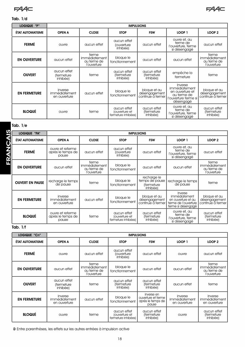
�8
Tab. 1/d
Tab. 1/e
Tab. 1/f
LOGIQUE “P” IMPULSIONS
ÉTAT AUTOMATISME OPEN A CLOSE STOP FSW LOOP 1 LOOP 2
FERMÉ ouvre aucun effetaucun effet(ouverture inhibée)
aucun effetouvre et, au
terme de l’ouverture, ferme
si désengagéaucun effet
EN OUVERTURE aucun effetferme
immédiatement au terme de l’ouverture
bloque lefonctionnement aucun effet aucun effet
ferme immédiatement
au terme de l’ouverture
OUVERTaucun effet(fermeture inhibée)
fermeaucun effet (fermeture inhibée)
aucun effet (fermeture inhibée)
empêche la fermeture ferme
EN FERMETUREinverse
immédiatement en ouverture
aucun effet bloque lefonctionnement
bloque et au désengagement continue à fermer
Inverse immédiatement en ouverture et
au terme de l’ouverture ferme si
désengagé
bloque et au désengagement continue à fermer
BLOQUÉ ouvre fermeaucun effet (ouverture et
fermeture inhibées)
aucun effet (fermeture inhibée)
ouvre et, au terme de
l’ouverture, ferme si désengagé
aucun effet (fermeture inhibée)
Entre parenthèses, les effets sur les autres entrées à impulsion active
LOGIQUE “PA” IMPULSIONS
ÉTAT AUTOMATISME OPEN A CLOSE STOP FSW LOOP 1 LOOP 2
FERMÉouvre et referme
après le temps de pause
aucun effetaucun effet (ouverture inhibée)
aucun effetouvre et, au
terme de l’ouverture, ferme
si désengagéaucun effet
EN OUVERTURE aucun effetferme
immédiatement au terme de l’ouverture
bloque lefonctionnement aucun effet aucun effet
ferme immédiatement
au terme de l’ouverture
OUVERT EN PAUSE recharge le temps de pause ferme bloque le
fonctionnement
recharge le temps de pause
(fermeture inhibée)
recharge le temps de pause ferme
EN FERMETUREinverse
immédiatement en ouverture
aucun effet bloque lefonctionnement
bloque et au désengagement continue à fermer
Inverse immédiatement
en ouverture et au terme de l’ouverture ferme si désengagé
bloque et au désengagement continue à fermer
BLOQUÉouvre et referme
après le temps de pause
fermeaucun effet (ouverture et
fermeture inhibées)
aucun effet (fermeture inhibée)
ouvre et, au terme de
l’ouverture, ferme si désengagé
aucun effet (fermeture inhibée)
LOGIQUE “Cn” IMPULSIONS
ÉTAT AUTOMATISME OPEN A CLOSE STOP FSW LOOP 1 LOOP 2
FERMÉ ouvre aucun effetaucun effet (ouverture inhibée)
aucun effet ouvre aucun effet
EN OUVERTURE aucun effetferme
immédiatement au terme de l’ouverture
bloque lefonctionnement aucun effet aucun effet
ferme immédiatement
au terme de l’ouverture
OUVERTaucun effet(fermeture inhibée)
fermeaucun effet (fermeture inhibée)
aucun effet (fermeture inhibée)
aucun effet ferme
EN FERMETUREinverse
immédiatement en ouverture
aucun effet bloque lefonctionnement
inverse en ouverture et ferme après le temps de
pause
inverse immédiatement
en ouverture
inverse immédiatement
en ouverture
BLOQUÉ ouvre fermeaucun effet (ouverture et
fermeture inhibées)
aucun effet (fermeture inhibée)
ouvreaucun effet (fermeture inhibée)
FRA
NÇ
AIS

�9
Tab. 1/i
Tab. 1/g
Tab. 1/h
LOGIQUE “CA” IMPULSIONS
ÉTAT AUTOMATISME OPEN A CLOSE STOP FSW LOOP 1 LOOP 2
FERMÉouvre et referme
après le temps de pause
aucun effetaucun effet (ouverture inhibée)
aucun effetouvre et referme
après le temps de pause
aucun effet
EN OUVERTURE aucun effetferme
immédiatement au terme de l’ouverture
bloque lefonctionnement aucun effet aucun effet
ferme immédiatement
au terme de l’ouverture
OUVERT EN PAUSE recharge le temps de pause ferme bloque le
fonctionnement
recharge le temps de pause
(fermeture inhibée)
recharge le temps de pause ferme
EN FERMETUREinverse
immédiatement en ouverture
aucun effet bloque lefonctionnement
inverse en ouverture et ferme après le temps de
pause
inverse immédiatement
en ouverture
inverse immédiatement
en ouverture
BLOQUÉouvre et referme
après le temps de pause
fermeaucun effet (ouverture et
fermeture inhibées)
aucun effet (fermeture inhibée)
ouvre et referme après le temps de
pause
aucun effet (fermeture inhibée)
LOGIQUE “rb” IMPULSIONS
ÉTAT AUTOMATISME OPEN A CLOSE STOP FSW LOOP 1 LOOP 2
FERMÉouvre et referme
après le temps de pause
aucun effetaucun effet (ouverture inhibée)
aucun effetouvre et referme
après le temps de pause
aucun effet
EN OUVERTURE aucun effetinverse
immédiatement en fermeture
bloque lefonctionnement aucun effet aucun effet aucun effet
OUVERT EN PAUSE recharge le temps de pause ferme bloque le
fonctionnement
recharge le temps de pause
(fermeture inhibée)
recharge le temps de pause
recharge le temps de pause
(fermeture inhibée)
EN FERMETUREinverse
immédiatement en ouverture
aucun effet bloque lefonctionnement
inverse immédiatement
en ouverture
inverse immédiatement
en ouverture
inverse immédiatement
en ouverture
BLOQUÉouvre et referme
après le temps de pause
fermeaucun effet (ouverture et
fermeture inhibées)
aucun effet (fermeture inhibée)
ouvre et referme après le temps de
pause
aucun effet (fermeture inhibée)
Entre parenthèses, les effets sur les autres entrées à impulsion
LOGIQUE “C” COMMANDES MAINTENUES IMPULSIONS
ÉTAT AUTOMATISME OPEN A CLOSE STOP FSW LOOP 1 LOOP 2
FERMÉ ouvre aucun effetaucun effet (ouverture inhibée)
aucun effet aucun effet aucun effet
EN OUVERTURE / aucun effet bloque lefonctionnement aucun effet aucun effet aucun effet
OUVERTaucun effet(fermeture inhibée)
ferme bloque lefonctionnement aucun effet
aucun effet(fermeture inhibée)
aucun effet(fermeture inhibée)
EN FERMETUREinverse
immédiatement en ouverture
/ bloque lefonctionnement
bloque lefonctionnement
bloque lefonctionnement
bloque lefonctionnement
BLOQUÉ ouvre fermeaucun effet (ouverture et
fermeture inhibées)
aucun effet (fermeture inhibée)
aucun effet(fermeture inhibée)
aucun effet(fermeture inhibée)
active
FRA
NÇ
AIS
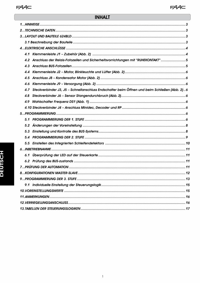
�
INHALT1....HINWEISE......................................................................................................................................................3
2....TECHNISCHE.DATEN......................................................................................................................................3
3....LAYOUT.UND.BAUTEILE.624BLD.....................................................................................................................3
3.1.Beschreibung.der.Bauteile....................................................................................................................3
4....ELEKTRISCHE.ANSCHLÜSSE...........................................................................................................................4
4.1...Klemmenleiste.J1.–.Zubehör.(Abb..2).................................................................................................4
4.2...Anschluss.der.Relais-Fotozellen.und.Sicherheitsvorrichtungen.mit.“RUHEKONTAKT”..........................5
4.3...Anschluss.BUS-Fotozellen.....................................................................................................................5
4.4...Klemmenleiste.J2.–.Motor,.Blinkleuchte.und.Lüfter.(Abb..2)...............................................................6
4.5...Anschluss.J8.–.Kondensator.Motor.(Abb..2)........................................................................................6
4.6...Klemmenleiste.J9.–.Versorgung.(Abb..2)............................................................................................6
4.7...Steckverbinder.J3,.J5.–.Schnellanschluss.Endschalter.beim.Öffnen.und.beim.Schließen.(Abb..2)...6
4.8...Steckverbinder.J6.–.Sensor.Stangendurchbruch.(Abb..2)...................................................................6
4.9...Wahlschalter.Frequenz.DS1.(Abb..1)...................................................................................................6
4.10.Steckverbinder.J4.–.Anschluss.Minidec,.Decoder.und.RP..................................................................6
5....PROGRAMMIERUNG.....................................................................................................................................6
5.1...PROGRAMMIERUNG.DER.1..STUFE........................................................................................................6
5.2...Änderungen.der.Voreinstellung..........................................................................................................8
5.3...Einstellung.und.Kontrolle.des.BUS-Systems..........................................................................................8
5.4...PROGRAMMIERUNG.DER.2..STUFE........................................................................................................9
5.5...Einstellen.des.Integrierten.Schleifendetektors....................................................................................10
6....INBETRIEBNAHME..........................................................................................................................................11
6.1...Überprüfung.der.LED.auf.der.Steuerkarte..........................................................................................11
6.2...Prüfung.des.BUS-zustands...................................................................................................................11
7....PRÜFUNG.DER.AUTOMATION........................................................................................................................11
8....KONFIGURATIONEN.MASTER-SLAVE...............................................................................................................12
9....PROGRAMMIERUNG.DER.3..STUFE................................................................................................................13
9.1...Individuelle.Einstellung.der.Steuerungslogik.......................................................................................15
10..VOREINSTELLUNGSWERTE.............................................................................................................................15
11..ANMERKUNGEN............................................................................................................................................16
12..VERRIEGELUNGSANSCHLUSS.........................................................................................................................16
13..TABELLEN.DER.STEUERUNGSLOGIKEN............................................................................................................17
DEUTSC
H

�
CE - KONFORMITÄTSERKLÄRUNG
Der Hersteller: FAAC S.p.A.
Anschrift: Via Calari, �0 - 40069 Zola Predosa BOLOGNA - ITALIEN
Erklärt, dass: Das elektronische Gerät 6�4BLD
• den wesentlichen Sicherheitsanforderungen der folgenden EWG Richtlinien entspricht
�006/95/EG Niederspannungsrichtlinie �004/�08/EG Richtlinie zur elektromagnetischen Verträglichkeit
Zusätzliche Anmerkung: Dieses Produkt wurde den Prüfungen in einer typischen homogenen Konfiguration unterzogen (alle Produkte stammen aus der Produktion der Firma FAAC S.p.A.
Bologna, �. Januar �0�0
Der Geschäftsführer A. Marcellan
HINWEISE FÜR DIE INSTALLATIONALLGEMEINE SICHERHEITSVORSCHRIFTEN
1) ACHTUNG!UmdiePersonensicherheitzugewährleisten,solltedieAnleitungaufmerksam befolgt werden. Eine falsche Montage oder ein fehlerhafterBetriebdesProdukteskönnenzuschwerwiegendenVerletzungenführen.
2) Die Anleitung aufmerksam lesen, bevor mit der Montage des Produktesbegonnenwird.
3) DasVerpackungsmaterial(Kunststoff,Styroporusw.)darfnichtinReichweitevon Kindern aufbewahrt werden, da es eine potentielle Gefahrenquelledarstellt.
4) DieAnleitungmussgriffbereitaufbewahrtwerden,umauchinZukunftBezugaufsienehmenzukönnen.
5) DiesesProduktwurdeausschließlichfürdenindiesenUnterlagenangegebenenGebrauch entwickelt und hergestellt. Jeder andere Gebrauch, der nichtausdrücklich angegeben ist, könnte die Unversehrtheit des Produktesbeeinträchtigenund/odereineGefahrenquelledarstellen.
6) DieFirmaFAAClehntjedeHaftungfürSchädenab,diedurchunsachgemäßenoder nicht bestimmungsgemäßen Gebrauch der Automatik verursachtwerden.
7) DasGerätdarfnichtinexplosionsgefährdetenUmgebungenmontiertwerden.EntflammbareGasebzw.RauchstelleneinschwerwiegendesSicherheitsrisikodar.
8) DiemechanischenBauelementemüssendenAnforderungenderNormenEN12604undEN12605entsprechen.
Für Länder,dienichtderEuropäischenGemeinschaftangehören, sind fürdie Gewährleistung eines entsprechenden Sicherheitsniveaus neben dennationalengesetzlichenBezugsvorschriftendieobenaufgeführtenNormenzubeachten.
9) DieFirmaFAACübernimmtkeineHaftungimFallevonnichtfachgerechtenAusführungenbeiderHerstellungderanzutreibendenSchließvorrichtungensowiebeiDeformationen,dieeventuellbeimBetriebentstehen.
10) DieMontagemussunterBeachtungderRichtlinienEN12453undEN12445erfolgen.
Für Länder,dienichtderEuropäischenGemeinschaftangehören, sind fürdie Gewährleistung eines entsprechenden Sicherheitsniveaus neben dennationalengesetzlichenBezugsvorschriftendieobenaufgeführtenNormenzubeachten.
11) Vor der Ausführung jeglicher Eingriffe auf der Anlage ist die elektrischeVersorgungauszuschalten.
12) Auf dem Versorgungsnetz der Automatik ist ein allpolige Schalter mitÖffnungsabstandderKontaktevonmindestens3mmeinzubauen.Darüberhinaus wird der Einsatz eines Magnetschutzschalters mit 6 A mit allpoligerAbschaltungempfohlen.
13) Essollteüberprüftwerden,obvorderAnlageeinDifferentialschaltermiteinerAuslöseschwellevon0,03Avorgesehenist.
14) Essollteüberprüftwerden,obdieErdungsanlagefachgerechtausgeführtwurde.DieMetallteilederSchließungsolltenandieseAnlageangeschlossenwerden.
15) DieAutomationverfügtübereineeingebauteSicherheitsvorrichtungfürdenQuetschschutz,dieauseinerDrehmomentkontrollebesteht.EsistinjedemFalleerforderlich,derenEingriffsschwellegemäßderVorgabenderunterPunkt10angegebenenVorschriftenzuüberprüfen.
16) Die Sicherheitsvorrichtungen (Norm EN 12978) ermöglichen den Schutzeventueller Gefahrenbereiche vor mechanischen Bewegungsrisiken, wiezumBeispielQuetschungen,MitschleifenoderSchnittverletzungen.
17) FürsämtlicheAnlagenwirdderEinsatzvonmindestenseinemLeuchtsignal(z.B. FAACLIGHT) sowie eines Hinweisschildes empfohlen, das über eineentsprechendeBefestigungmitdemAufbaudesTorsverbundenwird.DarüberhinaussinddieunterPunkt"16"erwähntenVorrichtungeneinzusetzen.
18) Die Firma FAAC lehnt jede Haftung hinsichtlich der Sicherheit und desstörungsfreienBetriebsderAutomatikab,wennKomponentenaufderAnlageeingesetztwerden,dienichtimHauseFAAChergestelltwurden.
19) BeiderWartungsolltenausschließlichOriginalteilederFirmaFAACverwendetwerden.
20) An den Bestandteilen des Automationssystems dürfen keinesfallsVeränderungenvorgenommenwerden.
21) DerMonteurmuss inNotfällensämtliche Informationen inBezugaufdenmanuellenBetriebdesSystems liefernunddemBetreiberderAnlagedieGebrauchsanleitung,diedemProduktbeigelegtist,übergeben.
22) WederKindernochErwachsenedürfensichwährenddesBetriebs inderunmittelbarenNähederAutomationaufhalten.
23) DieFunksteuerungenundalleanderenImpulsgebermüssenaußerhalbderReichweitevonKindernaufbewahrtwerden,umeinversehentlichesAktivierenderAutomationzuvermeiden.
24) Der Durchgang/die Durchfahrt darf nur bei stillstehender Automationerfolgen.
25) Der Betreiber darf keinerlei Reparaturen oder direkte Eingriffe an derAutomationausführen,sondernmusssichhierfürausschließlichanqualifiziertesFachpersonalwenden.
26) Wartung: Mindestens alle 6 Monate muss die Funktionstüchtigkeit derAnlage, insbesondere die Funktionstüchtigkeit der Sicherheits- und derEntriegelungsvorrichtungen überprüft werden (falls vorhanden auch dieSchubkraftdesAntriebs).
27) AlleVorgehensweisen,dienichtausdrücklichindervorliegendenAnleitungvorgesehensind,sindnichtzulässig.
DEUTSC
H

�
.1.. HINWEISE
Achtung: Vor Arbeiten am elektronischen Steuergerät (Anschlüsse, Wartung usw.) stets die Stromzufuhr unterbrechen.- Vor der Anlage einen thermomagnetischen differenzialen Schutzschalter mit entsprechender Auslöseschwelle einbauen.- Das Erdungskabel an die entsprechende Klemme an den Steckverbinder J9 des Steuergeräts anschließen (siehe Abb. 2).- Die Versorgungskabel stets von den Steuer- und Sicherheitskabeln (Taste, Empfänger, Fotozellen usw.) trennen. Um elektrische
Störungen zu vermeiden, getrennte Ummantelungen oder abgeschirmte Kabel (mit geerdeter Abschirmung) verwenden.
ELEKTRONISCHES STEUERGERÄT 624 BLD
.3.. LAYOUT.UND.BAUTEILE.624BLD
Anschlussspannung *��0 V~ (+6% -�0%) - 50/60 Hz
oder��5 V~ (+6% -�0%) - 50/60 Hz
aufgenommene Leistung 7 W
Max. Last Motor �000 W
Zubehörversorgung �4 Vdc
Max. Stromstärke Zubehör 500 mA
Temperatur am Aufstellungsort von -�0 °C bis +55 °C
Schmelzsicherungen *F� = F �0A - �50V F� = T 0,8A - �50V
oderF� = F �0A - ��0V F� = T 0,8A - ��0V
Betriebszeit programmierbar (von 0 bis 4 Min.)
Pausenzeit programmierbar (von 0 bis 4 Min.)
Schubkraft des Motors programmierbar auf 50 Stufen
Programmierung � Programmierstufen um den flexiblen Einsatz zu verstärken
SchnellanschlussSchnellanschluss der Karte mit 5 Pin
MinidecDecoder, Empfänger RP/RP�
programmierbare Ausgänge
4 programmierbare Ausgängemit �8 verschiedenen Funktionen
EigenschaftenSteuerung der Abbremsungen,
Multifunktionsdisplay, BUS-Technik und INTEGRIERTER METALLDETEKTOR
* Anschlussspannung und Sicherungen hängen von der jeweiligen Ausführung ab
.2.. TECHNISCHE.DATEN
3.1.BESCHREIBUNG.DER.BAUTEILE
DL DISPLAY FÜR ANZEIGE UND PROGRAMMIERUNG
LED LED FÜR DIE KONTROLLE DES ZUSTANDS DER EINGÄNGE
J1 NIEDERSPANNUNGSKLEMMENLEISTE
J2 KLEMMENLEISTE FÜR DEN ANSCHLUSS VON MOTOR, BLINKLEUCHTE UND LÜFTER
J3 STECKVERBINDER ENDSCHALTER BEIM ÖFFNEN
J4 ANSCHLUSS DECODER / MINIDEC / EMPFÄNGER RP
J5 STECKVERBINDER ENDSCHALTER BEIM SCHLIESSEN
J6 ANSCHLUSS SENSOR BALKENBRUCH
J8 ANSCHLUSS ANLAUFKONDENSATOR MOTOR
J9 KLEMMENLEISTE VERSORGUNG ��0 VAC
DS1 WAHLSCHALTER FREQUENZEN LOOP � und LOOP �
F1 SCHMELZSICHERUNG MOTOREN UND PRIMÄRWICKLUNG TRANSFORMATOR (F 5A)
F2 SCHMELZSICHERUNG NIEDERSPANNUNG UND ZUBEHÖR (T 800 mA)
F PROGRAMMIERTASTE “F”
+ PROGRAMMIERTASTE “+”
- PROGRAMMIERTASTE “-”
TF1 TRANSFORMATOR
Abb. 1
DEUTSC
H

4
.4.. ELEKTRISCHE.ANSCHLÜSSE
Für den Anschluss der Fotozellen und der
Sicherheitsvorrichtungen wird auf den Abschnitt
4.2 verwiesen
BLA
UW
ANLAUFKONDENSATOR MOTOR
LÜFTER
MOTOR
BALKENBRUCH
Abb. 2
LOOP 1 - Magnetschleife LOOP 1 (OPEN - Klemmen 1-2): ÖFFNUNGSFUNKTIONLOOP 2 - Magnetschleife LOOP 2 (SAFETY/CLOSE – Klemmen 3-4): SICHERHEITS-/SCHLIESSFUNKTIONOPEN - Open-Impuls (Arbeitskontakt - Klemme 5): jeder beliebige Impulsgeber (Bsp.: Taster), der bei Schließen eines Kontakts einen Impuls für das Öffnen und/oder Schließen der Schranke erzeugt.CLOSE - Close-Impuls (Arbeitskontakt - Klemme 6): jeder beliebige Impulsgeber (Bsp.: Taster), der bei Schließen eines Kontakts einen Impuls für das Schließen der Schranke erzeugt.FSW - Kontakt der Sicherheitsvorrichtungen beim Schließen (Ruhekontakt - Klemme 7): Die Sicherheitsvorrichtungen beim Schließen haben die Aufgabe, den von der Bewegung der Schranke während der Schließphase betroffenen Bereich durch Umkehrung der Bewegungsrichtung abzusichern. Diese Vorrichtungen betätigen sich beim Öffnungszyklus niemals. Wenn die Sicherheitsvorrichtungen beim Schließen bei offener Automation belegt werden, verhindern sie die Schließbewegung.
Wenn.die.Sicherheitsvorrichtungen.beim.Schließen.nicht.angeschlossen.werden,.die.Klemmen.FSW.und.GND.überbrücken.(Abb..6).
STOP - Stopp-Kontakt (Ruhekontakt - Klemme 8): jede beliebige Vorrichtung (Bsp.: Taste), die durch Öffnen eines Kontakts die Bewegung der Automation anhalten kann.
Wenn.die.Stopp-Vorrichtungen.nicht.angeschlossen.werden,.die.Klemmen.STOP.und.GND.überbrücken.(Abb..6).
EMERGENCY - NOT-Kontakt (Ruhekontakt - Klemme 9): jeder beliebige Schalter, der bei Betätigung im Notfall eine Öffnung der Schranke bewirkt und den Betrieb bis zur Zurücksetzung des Kontakts hemmt.
Wenn.keine.Notvorrichtungen.angeschlossen.werden,.die.Klemmen.EMERGENCY.und.GND.überbrücken.(Abb..6).
GND ( Klemmen 10-11-19) – Minuspol Zubehörversorgung24 Vdc ( Klemmen 12-13) – Pluspol Zubehörversorgung
. Die. Höchstbelastung. des. Zubehörs. beträgt. 500. mA.. Zur. Berechnung. der. Aufnahmewerte. wird. auf. die.Betriebsanleitungen.der.einzelnen.Zubehörteile.verwiesen.
OUT 1 - Ausgang 1 Open-Collector GND (Klemme 14): Der Ausgang kann immer in einer der bei der Programmierung der zweiten Stufe beschriebenen Funktionen eingestellt werden (siehe Abschn. 5.�). Der Default-Wert ist FAILSAFE. Maximale Last: 24 Vdc bei 100 mA.OUT 2 - Ausgang 2 Open-Collector GND (Klemme 15): Der Ausgang kann in einer der bei der Programmierung der zweiten Stufe beschriebenen Funktionen eingestellt werden (siehe Abschn. 5.�). Der Default-Wert ist Schranke GESCHLOSSEN. Maximale Last: 24 Vdc bei 100 mA.OUT 3 - RELAIS-Ausgang 3 (Klemme 16-17): Der Ausgang kann in einer der bei der Programmierung der zweiten Stufe beschriebenen Funktionen eingestellt werden (siehe Abschn. 5.�). Der Default-Wert ist KONTROLLLEUCHTE. Maximale Last: 24 Vdc oder Vac bei 500 mA.
. Damit.der.einwandfreie.Betrieb.des.Systems.nicht.beeinträchtigt.wird,.die.in.der.Abb..2.angegebene.Leistung.nicht.überschreiten.
OUT 4 - Ausgang 4 Open-Collector +24VDC (Klemme 18): Der Ausgang kann in einer der bei der Programmierung der zweiten Stufe beschriebenen Funktionen eingestellt werden (siehe Abschn. 5.�). Der Default-Wert für ALLE VOREINSTELLUNGEN ist BUS-KOMMUNIKATION.Maximale Last: 24 Vdc bei 100 mA.
4.1.. KLEMMENLEISTE.J1.–.ZUBEHÖR.(ABB..2)
230 V~oder 115 V~60W max * 230 V~
oder 115 V~50/60 Hz *
* Ausführung Steuerung ��0 V~oder Ausführung Steuerung ��5 V~
DEUTSC
H

5
191816 17151412 1310 118 96 74 52 31
OPEN
A
STOP
LOO
P1
LOO
P2
LOO
P2
LOO
P1
CLO
SE
FSW
EMERG
ENC
Y
OUT1
OUT2
OUT4
OUT3
GN
D
GN
D
GN
D
+24V
+24V
OUT3
J1
Bei der Steuerkarte 6�4 BLD ist der Anschluss von Sicherheitsvorrichtungen beim Schließen vorgesehen, die nur bei der Schließbewegung der Schranke auslösen und daher dafür geeignet sind, den Schließbereich der Durchfahrt gegen Aufprallgefahr abzusichern.
. .Wenn.zwei.oder.mehr.Sicherheitsvorrichtungen.(Ruhekontakte).angeschlossen.werden.müssen,.sind.diese.in.Reihe.zu.schalten.(siehe.hierzu.Abb..3,.4,.5.unter.der.Aufschrift.“SAFE”).
4.2.ANSCHLUSS.DER.RELAIS-FOTOZELLEN.UND.SICHERHEITSVORRICHTUNGEN.MIT.“RUHEKONTAKT”
Anschluss von 1 Paar Fotozellen beim Schließen Anschluss von 2 Paar Fotozellen beim Schließen
Abb. 5
Abb. 3
Anschluss ohne Sicherheitsvorrichtungen
Abb. 6
4.3.ANSCHLUSS.BUS-FOTOZELLEN
1. Paar Fotozellen 2. Paar Fotozellenpaar
Abb. 7
Die BUS-Fotozellen sind am Steuergerät 6�4 BLD gemäß Darstellung in Abb. 7 ALLE PARALLEL über eine einzige Versorgungs-/Kommunikationsleitung angeschlossen.
.DieBUS-FotozellenweisenkeineAnschlusspolaritätauf.
An die Karte können maximal 8 Paar BUS-Fotozellen angeschlossen werden.Die Fotozellen sind nach Menge in folgende Gruppen unterteilt:
Paare Fotozellen beim Schließen: max 7Paare Fotozellen für OPEN-Impuls: max �
Sicherstellen, dass in der Programmierstufe � folgende Werte festgelegt sind:
o4 = 00 und P4 = no
Anschluss von 1 Paar Fotozellen beim Schließen mit Sicherheitsvorrichtung FAIL SAFE
In der �. Programmierstufe festlegen : FS = Y und o 1 = 00Abb. 4
DEUTSC
H

6
RP / RP2
624BLDJ4
4.4.. KLEMMENLEISTE. J2. –. MOTOR,. BLINKLEUCHTE. UND.LÜFTER.(ABB..2)
M (COM-MOT1-MOT2): Anschluss des MotorsLAMP (LAMP-COM): Ausgang BlinkleuchteLÜFTER (FAN-COM): Ausgang Lüfter
4.6.. KLEMMENLEISTE.J9.–.VERSORGUNG.(ABB..2)
PE : ErdungN : Versorgung ��0 V~ oder ��5 V~ ( Nullleiter )L : Versorgung ��0 V~ oder ��5 V~ ( Anlage )
. . Für.den.störungsfreien.Betrieb.muss.die.Karte.an.die.Erdung.der.Anlage.angeschlossen.werden. . Vor . das . Sys tem. e inen.entsprechenden. thermomagnetischen.Fehlerstrom-Schutzschalter.schalten.
4.5.. ANSCHLUSS.J8.–.KONDENSATOR.MOTOR.(ABB..2)
Steckverbinder mit Schnellanschluss für die Verbindung des Anlaufkondensators des Motors.
4.7.. STECKVERBINDER. J3,. J5. –. SCHNELLANSCHLUSS.ENDSCHALTER.BEIM.ÖFFNEN.UND.BEIM.SCHLIESSEN.(ABB..2)
Steckverbinder mit Schnellanschluss für die Verbindung der Endschalter beim Öffnen (J�) und beim Schließen (J5).
Nach der Positionierung der BUS-Fotozellen ist die Adresse jedes Paars durch die Kombination der DIP-SWITCH an jeder Fotozelle auszuwählen.
.. Sowohl.am.Sender.als.auch.am.Empfänger.desselben.Paars.DIE.GLEICHE.ausgewählte.Dip-Switch-ADRESSE.festlegen.
..Sicherstellen,.dass.die.verschiedenen.Paare.Fotozellen.unterschiedliche.Adressen.haben.(das.heißt,.zwei.oder.mehreren.Paaren.dürfen.nicht.dieselbe.Adresse.zugeordnet.werden
. . Wenn.kein.BUS-Zubehör.verwendet.wird,.sind.die.Klemmen.18.und.19.frei.zu.lassen.
In der Tab. 4 sind die Programmierungen der Dip-Switch im Sender und Empfänger der BUS-Fotozellen aufgeführt.Tab. 4 - Adressierung der BUS-Fotozellen-PAARE
Dip1 Dip2 Dip3 Dip4Nummer
des Paars
Typ
ON OFF OFF OFF �. Paar
Fotozellen beim
SCHLIESSEN
ON OFF OFF ON �. Paar
ON OFF ON OFF �. Paar
ON OFF ON ON 4. Paar
ON ON OFF OFF 5. Paar
ON ON OFF ON 6. Paar
ON ON ON OFF 7. Paar
ON ON ON ON einzigesPaar
OPEN- IMPULS
DIP-SWITCH SENDER
DIP-SWITCH EMPFÄNGER
GLE ICHE ADRESSE
. Für.die.Funktionstüchtigkeit.des.installierten.BUS-Zubehörs. auf. die. Steuerung.einspeichern.. Siehe. hierzu. Erklärung. im.Kapitel.5.3.
4.10..STECKVERBINDER.J4.–.ANSCHLUSS.MINIDEC,.DECODER.UND.RP
Dieser Steckverbinder wird für den Schnellanschluss von Minidec, Decoder und Empfängern RP/RP� eingesetzt.Wenn ein �-Kanal-Empfänger vom Typ RP� verwendet wird, können die OPEN- und CLOSE-Impulse der Automation direkt von einer �-Kanal-Funksteuerung gesendet werden.Wenn ein Empfänger mit einem Kanal vom Typ RP verwendet wird, kann nur der OPEN-Impuls gesteuert werden.Das Zubehör mit der Seite der Bauteile zur Innenseite der Karte hin gerichtet einsetzen.
. Die. Karte. darf. NUR. eingesetzt. und.herausgenommen.werden,.nachdem.die.Spannung.unterbrochen.wurde.
4.8..STECKVERBINDER.J6.–.SENSOR.BALKENBRUCH.(ABB..2)Steckverbinder mit Schnellanschluss für die Verbindung des Sensors bei Balkenbruch (wenn vorhanden). Wenn dieser Sensor nicht eingebaut ist, die mitgelieferte Überbrückung beibehalten.
4.9.. WAHLSCHALTER.FREQUENZ.DS1.(ABB..1)Dieser DIP-SWITCH-Schalter wird zur Einstel lung der Betriebsfrequenz HOCH oder NIEDRIG der Schleifen zur Fahrzeugerfassung verwendet. (siehe Kapitel 5.5).
DieÄnderungderProgrammierparameteristsofortwirksam,währenddieendgültigeSpeicherung erst dann erfolgt, wenndie Programmierung beendet und derAnzeigemodusdesZustandsderAutomationerneutaufgerufenwird.WenndieStromzufuhrzum Gerät unterbrochen wird, bevorder Anzeigemodus des Zustands erneutaufgerufenwird,gehenallevorgenommenenÄnderungenverloren.
Die Rückkehr zum Anzeigemodus desZustands istan jederbeliebigenStellederProgrammierungundinjederStufemöglich,undzwardurchgleichzeitigesDrückenderTastenFund-.
.5.. PROGRAMMIERUNGFür die Programmierung der Betriebsart der Automation muss der Modus “PROGRAMMIERUNG“ aufgerufen werden. Die Programmierung gliedert sich in drei Teile: 1. STUFE,2.STUFEund 3.STUFE.
5.1.. PROGRAMMIERUNG.DER.1..STUFE
Die PROGRAMMIERUNG DER �. STUFE wird mit der Taste F aufgerufen:• Bei (anhaltendem) Drücken der Taste erscheint die
Bezeichnung der ersten Funktion auf dem Display.• Wenn die Taste losgelassen wird, zeigt das Display den
Wert der Funktion, der mit den Tasten + und - geändert werden kann
• Bei erneutem (anhaltendem) Drücken der Taste F erscheint die Bezeichnung der nächsten Funktion auf dem Display usw.
• Bei der letzten Funktion wird die Programmierung durch Drücken der Taste F beendet und das Display zeigt erneut den Zustand der Eingänge an.
Beispiel für den Anschluss eines Funkzubehörs
Abb. 8
DEUTSC
H
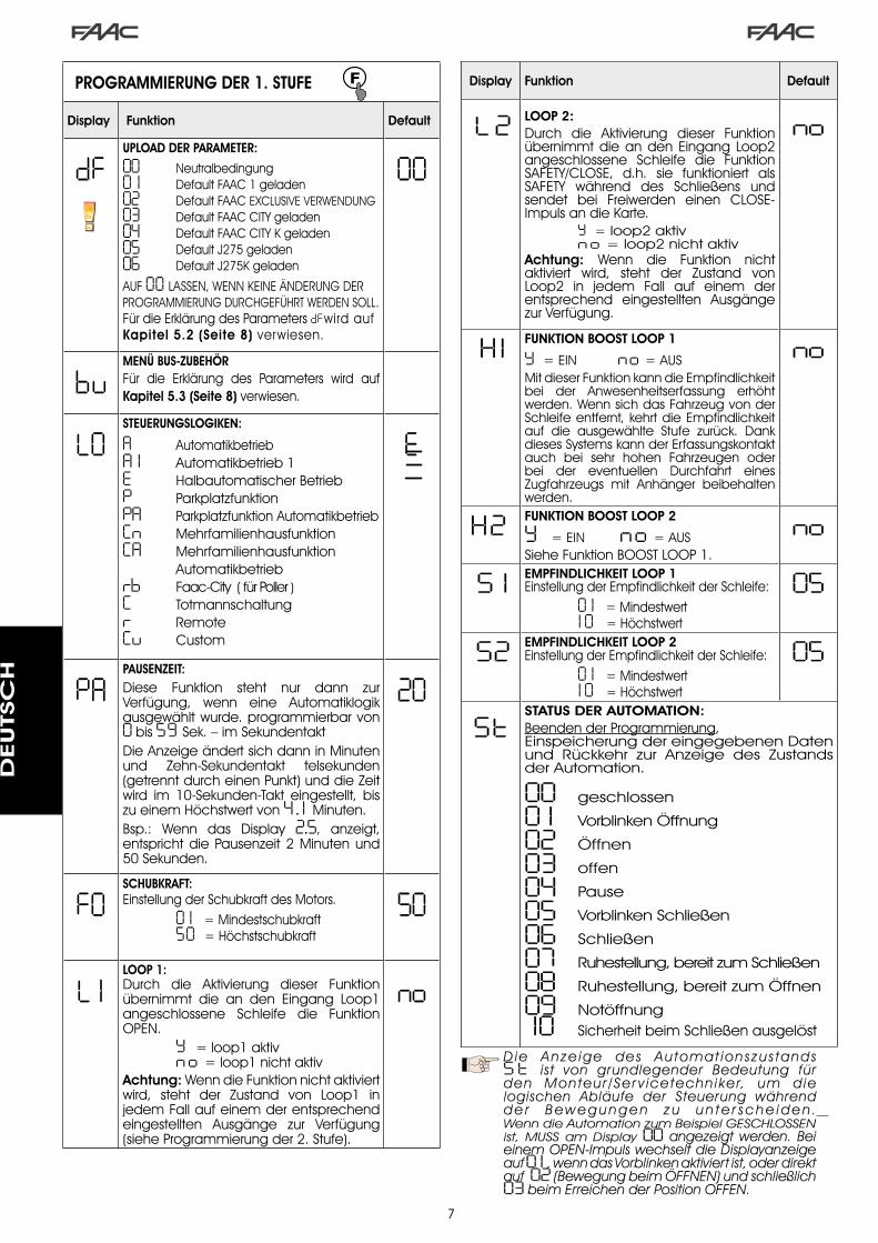
7
PROGRAMMIERUNG DER 1. STUFE
Display Funktion Default
dFUPLOAD DER PARAMETER:
00 Neutralbedingung0 1 Default FAAC � geladen02 Default FAAC EXCLUSIVE VERWENDUNG03 Default FAAC CITY geladen04 Default FAAC CITY K geladen05 Default J�75 geladen06 Default J�75K geladen
AUF 00 LASSEN, WENN KEINE ÄNDERUNG DER PROGRAMMIERUNG DURCHGEFÜHRT WERDEN SOLL.Für die Erklärung des Parameters dFwird auf Kapitel 5.2 (Seite 8) verwiesen.
00
buMENÜ BUS-ZUBEHÖRFür die Erklärung des Parameters wird auf Kapitel 5.3 (Seite 8) verwiesen.
LOSTEUERUNGSLOGIKEN:
A AutomatikbetriebA 1 Automatikbetrieb �E Halbautomatischer BetriebP ParkplatzfunktionPA Parkplatzfunktion AutomatikbetriebCn MehrfamilienhausfunktionCA Mehrfamilienhausfunktion Automatikbetriebrb Faac-City ( für Poller )C Totmannschaltungr RemoteCu Custom
E
PAPAUSENZEIT:Diese Funktion steht nur dann zur Verfügung, wenn eine Automatiklogik ausgewählt wurde. programmierbar von 0 bis 59 Sek. – im SekundentaktDie Anzeige ändert sich dann in Minuten und Zehn-Sekundentakt telsekunden (getrennt durch einen Punkt) und die Zeit wird im �0-Sekunden-Takt eingestellt, bis zu einem Höchstwert von 4 . 1 Minuten.Bsp.: Wenn das Display 2.5, anzeigt, entspricht die Pausenzeit � Minuten und 50 Sekunden.
20
FOSCHUBKRAFT:Einstellung der Schubkraft des Motors. 0 1 = Mindestschubkraft 50 = Höchstschubkraft
50
L 1LOOP 1:Durch die Aktivierung dieser Funktion übernimmt die an den Eingang Loop� angeschlossene Schleife die Funktion OPEN. Y = loop� aktiv n o = loop� nicht aktivAchtung: Wenn die Funktion nicht aktiviert wird, steht der Zustand von Loop� in jedem Fall auf einem der entsprechend eingestellten Ausgänge zur Verfügung (siehe Programmierung der �. Stufe).
no
Display Funktion Default
L2 LOOP 2:Durch die Aktivierung dieser Funktion übernimmt die an den Eingang Loop� angeschlossene Schleife die Funktion SAFETY/CLOSE, d.h. sie funktioniert als SAFETY während des Schließens und sendet bei Freiwerden einen CLOSE-Impuls an die Karte. Y = loop� aktiv n o = loop� nicht aktivAchtung: Wenn die Funktion nicht aktiviert wird, steht der Zustand von Loop� in jedem Fall auf einem der entsprechend eingestellten Ausgänge zur Verfügung.
no
H1 FUNKTION BOOST LOOP 1
Y = EIN no = AUSMit dieser Funktion kann die Empfindlichkeit bei der Anwesenheitserfassung erhöht werden. Wenn sich das Fahrzeug von der Schleife entfernt, kehrt die Empfindlichkeit auf die ausgewählte Stufe zurück. Dank dieses Systems kann der Erfassungskontakt auch bei sehr hohen Fahrzeugen oder bei der eventuellen Durchfahrt eines Zugfahrzeugs mit Anhänger beibehalten werden.
no
H2 FUNKTION BOOST LOOP 2
Y = EIN no = AUSSiehe Funktion BOOST LOOP �.
no
S 1 EMPFINDLICHKEIT LOOP 1Einstellung der Empfindlichkeit der Schleife: 0 1 = Mindestwert 1 0 = Höchstwert
05
S2 EMPFINDLICHKEIT LOOP 2Einstellung der Empfindlichkeit der Schleife: 0 1 = Mindestwert 1 0 = Höchstwert
05
StSTATUS DER AUTOMATION:Beenden der Programmierung,Einspeicherung der eingegebenen Daten und Rückkehr zur Anzeige des Zustands der Automation.
00 geschlossen
0 1 Vorblinken Öffnung
02 Öffnen
03 offen
04 Pause
05 Vorblinken Schließen
06 Schließen
07 Ruhestellung, bereit zum Schließen
08 Ruhestellung, bereit zum Öffnen
09 Notöffnung 10 Sicherheit beim Schließen ausgelöst
D ie Anze ige des Automat ionszus tands S t ist von grundlegender Bedeutung fürden Monteur /Ser v icetechniker, um dielogischen Abläufe der Steuerung währendd e r B e w e g u n g e n z u u n t e r s c h e i d e n . WenndieAutomationzumBeispielGESCHLOSSENist, MUSS am Display00 angezeigt werden. BeieinemOPEN-ImpulswechseltdieDisplayanzeigeauf0 1 ,wenndasVorblinkenaktiviertist,oderdirektauf02(BewegungbeimÖFFNEN)undschließlich03beimErreichenderPositionOFFEN.
DEUTSC
H

8
Beispiel für eine Abfolge von am Display angezeigten Zuständen, ausgehend vom Status Schranke geschlossen:
In der Abfolge sind die Zustände 0 1 und 05 nicht aufgeführt, die jeweils dem Vorblinken beim Öffnen bzw. beim Schließen entsprechen.
00 geschlossen 02 Öffnen
04 Pause (wenn vorgesehen)
03 offen
06 Schließen
5.2.. ÄNDERUNGEN.DER.VOREINSTELLUNG
Die Änderung des Parameters dF ermöglicht das automatische Upload von 6 verschiedenen Konfigurationen mit der Änderung aller Programmierwerte auf allen Stufen durch vorgegebene Einstellungen.Diese Möglichkeit stellt einen praktischen Ausgangspunkt für die schnelle Programmierung des Steuergeräts 6�4 BLD für den Betrieb mit 6 verschiedenen Installationen dar.
Ausgewählt werden können die folgenden 6 VOREINSTELLUNGEN:
0 1 Default FAAC für Schranke 02 Default FAAC EXCLUSIVE VERWENDUNG03 Default für Produktreihe FAAC CITY �75 H600 und H80004 Default für FAAC CITY �75 H700 K05 Default für J�7506 Default für J�75KDamit das Upload der Werte einer der 6 Voreinstellungen wirksam wird, die gewünschte Voreinstellung ( 0 1 , 02 , 03 , 04 , 05 , 06 ) auswählen und die erste Programmierstufe beenden.BEISPIEL: Bei der Auswahl von 0 1 und dem Beenden der �. Programmierstufe werden alle FAAC-Produktionswerte geladen und können in den Tabellen der �., �. und �. Stufe der Spalte “Default” eingesehen werden. Die Steuerung 6�4 BLD ist daher für die Bewegung einer Schranke gestaltet.
. DIE.LAST.EINER.VOREINSTELLUNG.HEBT.ALLE.ZUVOR.AN. EINEM. BELIEBIGEN. PROGRAMMIERSCHRITT.VORGENOMMENEN. ÄNDERUNGEN. AUF.. WENN.KEINE.VOREINSTELLUNG.AUSGEWÄHLT.WERDEN.SOLL,.DEN.SCHRITT.dF .AUF.00..BEIBEHALTEN.
Im Unterschied zu den anderen speichert der Schritt dF, den ausgewählten Wert nicht, sondern zeigt immer wieder 00 als Standardzustand an.
Daher kann nicht erkannt werden, welche Voreinstellung zuvor festgelegt wurde.
Wenn keine Voreinstellung geladen werden soll, den Schritt dF IMMER auf 00 beibehalten und zum nächsten Programmierschritt übergehen.
Sicherstellen,. dass. das. gewünschte. Default-Upload. erfolgt. und. die. 1.. Programmierstufe.VOR.der.Änderung.anderer.Schritte.beenden,.um. zu. vermeiden,. dass. alle. vorgenommenen.Änderungen.aufgehoben.werden.
Für detaillierte Angaben zu jeder Voreinstellung wird auf das Kapitel �0 auf Seite �5 verwiesen.
5.3.. EINSTELLUNG.und.KONTROLLE.DES.BUS-SYSTEMSBei der Installation von einem oder mehreren BUS-Zubehörteilen (siehe Beschreibungen in Kapitel 4.�) müssen diese auf der Steuerung gespeichert werden.Für die Speicherung sind folgende Schritte vorzunehmen:- die erste Programmierstufe aufrufen, siehe Beschreibung in
Kap. 5.�.- Beim Programmierschritt bu die Taste F loslassen und für �
Sekunde die Taste + drücken.
Am Display wird für einen Augenblick -- eingeblendet, dann erneut der Standardzustand laut Abb. �0. Speichervorgang beendet.Der Programmierschritt bu hat auch die Funktion, den Zustand des Zubehörs mit BUS-Technik zu visualisieren. In der Abbildung 9 ist die exakte Übereinstimmung zwischen den Displaysegmenten und den Eingängen dargestellt.
Abb. 9
Segment EIN = Kontakt geschlossenSegment AUS = Kontakt offen
FSW CL = BUS-Fotozellen beim Schließen
OPEN = BUS-Fotozellen OPEN-ImpulsgeberNI
CHT
BEL
EGT
Bei der Konfiguration für den einwandfreien Betrieb der Automation müssen die drei waagrechten Segmente EIN sein (siehe Abb. 10.
Wenn die Fotozellen beim Schließen belegt sind, erlöschen das obere und das untere Segment, das zentrale Segment leuchtet weiterhin auf (siehe Abbildung ��).
Wenn das Paar OPEN-IMPULSGEBER belegt ist, leuchtet das entsprechende Segment für die Zeit der Belegung des Paars auf (siehe Darstellung in der Abbildung ��).
Abb. 10
Abb. 11
Abb. 12
Wenn das Fotozellenpaar OPEN-IMPULSGEBER belegt ist, wird ein Impuls zum Öffnen der Automation gesendet, und das Schließen ist bis zum Freiwerden gehemmt.
Wenn kein BUS-Fotozellenpaar in der Anlage eingebaut ist, zeigt der Programmierschritt bu die Visualisierung laut Abbildung 10.
Das BUS-Kommunikat ionssystem verwendet e ine Selbstdiagnosefunktion, die Signale für den falschen Anschluss oder die falsche Konfiguration des BUS-Zubehörs liefern kann.Bei einem KURZSCHLUSS an der BUS-Leitung BLINKT das Signal cc am Display (siehe Abbildung ��). Die hergestellten Anschlüsse überprüfen (Kap. 4.�).
Wenn mehrere Fotozellen die gleiche Adresse haben, BLINKT Er am Display (siehe Abbildung �4).
Abb. 13
Abb. 14
In diesem Fall alle festgelegten Adressen auf allen installierten Fotozellen überprüfen (siehe Kapitel 4.�).
DEUTSC
H
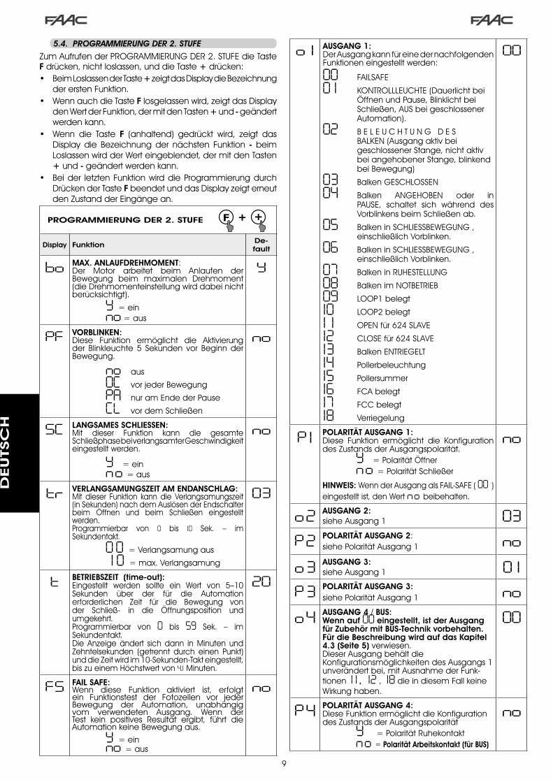
9
PROGRAMMIERUNG DER 2. STUFE
Display Funktion De-fault
bo MAX. ANLAUFDREHMOMENT:Der Motor arbeitet beim Anlaufen der Bewegung beim maximalen Drehmoment (die Drehmomenteinstellung wird dabei nicht berücksichtigt).
Y = ein no = aus
Y
PF VORBLINKEN:Diese Funktion ermöglicht die Aktivierung der Blinkleuchte 5 Sekunden vor Beginn der Bewegung.
no aus
OC vor jeder Bewegung
PA nur am Ende der Pause
CL vor dem Schließen
no
SC LANGSAMES SCHLIESSEN:Mit dieser Funktion kann die gesamte Schließphase bei verlangsamter Geschwindigkeit eingestellt werden.
Y = ein no = aus
no
tr VERLANGSAMUNGSZEIT AM ENDANSCHLAG:Mit dieser Funktion kann die Verlangsamungszeit (in Sekunden) nach dem Auslösen der Endschalter beim Öffnen und beim Schließen eingestellt werden.Programmierbar von 0 bis 10 Sek. – im Sekundentakt.
0 0 = Verlangsamung aus
1 0 = max. Verlangsamung
03
t BETRIEBSZEIT (time-out):Eingestellt werden sollte ein Wert von 5–�0 Sekunden über der für die Automation erforderlichen Zeit für die Bewegung von der Schließ- in die Öffnungsposition und umgekehrt.Programmierbar von 0 bis 59 Sek. – im Sekundentakt.Die Anzeige ändert sich dann in Minuten und Zehntelsekunden (getrennt durch einen Punkt) und die Zeit wird im �0-Sekunden-Takt eingestellt, bis zu einem Höchstwert von 4.1 Minuten.
20
FS FAIL SAFE:Wenn diese Funktion aktiviert ist, erfolgt ein Funktionstest der Fotozellen vor jeder Bewegung der Automation, unabhängig vom verwendeten Ausgang. Wenn der Test kein positives Resultat ergibt, führt die Automation keine Bewegung aus.
Y = ein no = aus
no
5.4.. PROGRAMMIERUNG.DER.2..STUFE
Zum Aufrufen der PROGRAMMIERUNG DER �. STUFE die Taste F drücken, nicht loslassen, und die Taste + drücken:• Beim Loslassen der Taste + zeigt das Display die Bezeichnung
der ersten Funktion.• Wenn auch die Taste F losgelassen wird, zeigt das Display
den Wert der Funktion, der mit den Tasten + und - geändert werden kann.
• Wenn die Taste F (anhaltend) gedrückt wird, zeigt das Display die Bezeichnung der nächsten Funktion - beim Loslassen wird der Wert eingeblendet, der mit den Tasten + und - geändert werden kann.
• Bei der letzten Funktion wird die Programmierung durch Drücken der Taste F beendet und das Display zeigt erneut den Zustand der Eingänge an.
o 1 AUSGANG 1:Der Ausgang kann für eine der nachfolgenden Funktionen eingestellt werden:
00 FAILSAFE
0 1 KONTROLLLEUCHTE (Dauerlicht bei Öffnen und Pause, Blinklicht bei Schließen, AUS bei geschlossener Automation).
02 B E L E U C H T U N G D E S BALKEN (Ausgang aktiv bei geschlossener Stange, nicht aktiv bei angehobener Stange, blinkend bei Bewegung)
03 Balken GESCHLOSSEN
04 Balken ANGEHOBEN oder in PAUSE, schaltet sich während des Vorblinkens beim Schließen ab.
05 Balken in SCHLIESSBEWEGUNG , einschließlich Vorblinken.
06 Balken in SCHLIESSBEWEGUNG , einschließlich Vorblinken.
07 Balken in RUHESTELLUNG
08 Balken im NOTBETRIEB
09 LOOP� belegt
10 LOOP� belegt
1 1 OPEN für 6�4 SLAVE
12 CLOSE für 6�4 SLAVE
13 Balken ENTRIEGELT
14 Pollerbeleuchtung
15 Pollersummer
16 FCA belegt
17 FCC belegt
18 Verriegelung
00
P 1 POLARITÄT AUSGANG 1:Diese Funktion ermöglicht die Konfiguration des Zustands der Ausgangspolarität. Y = Polarität Öffner no = Polarität Schließer
HINWEIS: Wenn der Ausgang als FAIL-SAFE ( 00 ) eingestellt ist, den Wert no beibehalten.
no
o2 AUSGANG 2:siehe Ausgang � 03
P2 POLARITÄT AUSGANG 2:siehe Polarität Ausgang � no
o3 AUSGANG 3:siehe Ausgang � 0 1
P3 POLARITÄT AUSGANG 3:siehe Polarität Ausgang � no
o4 AUSGANG 4 / BUS:Wenn auf 00 eingestellt, ist der Ausgang für Zubehör mit BUS-Technik vorbehalten. Für die Beschreibung wird auf das Kapitel 4.3 (Seite 5) verwiesen.Dieser Ausgang behält die Konfigurationsmöglichkeiten des Ausgangs � unverändert bei, mit Ausnahme der Funk-tionen 1 1 , 12 , 18 die in diesem Fall keine Wirkung haben.
00
P4 POLARITÄT AUSGANG 4:Diese Funktion ermöglicht die Konfiguration des Zustands der Ausgangspolarität Y = Polarität Ruhekontakt no = Polarität Arbeitskontakt (für BUS)
no
DEUTSC
H

�0
AS SERVICE-ANFORDERUNG (kombiniert mit den beiden nächsten Funktionen):Wenn diese Funktion aktiviert ist, wird am Ende des Count-Downs (einstellbar mit den beiden nächsten Funktionen „Zyklusprogrammierung“) der Ausgang LAMP im Abstand von �0 Sekunden 4 Sekunden lang aktiviert. Diese Funktion kann nützlich sein, um Arbeiten im Rahmen der Wartung zu programmieren.
Y = ein no = aus
no
nc ZYKLUSPROGRAMMIERUNG IN TAUSENDEN:Mit dieser Funktion kann ein Count-Down der Betriebszyklen der Anlage festgelegt werden. Der Wert ist einstellbar von 0 bis 99 (tausend Zyklen). Der angezeigte Wert aktualisiert sich mit der Abfolge der Zyklen und hängt mit dem Wert von nC (99 in Zusammenhang nc Verminderungen von nc entsprechen einer Erhöhung von nC ).Die Funktion kann in Kombination mit nC , eingesetzt werden, um die Nutzung der Anlage zu überprüfen und um die „Service-Anforderung“ in Anspruch zu nehmen.
00
nC ZYKLUSPROGRAMMIERUNG IN HUNDERTTAUSENDEN:Mit dieser Funktion kann ein Count-Down der Betriebszyklen der Anlage festgelegt werden. Der Wert ist einstellbar von 0 bis 99 (hunderttausend Zyklen). Der angezeigte Wert aktualisiert sich mit der Abfolge der Zyklen und hängt mit dem Wert von nc in Zusammenhang. (� Verminderung von nC entspricht 99 Verminderungen von nc ).Die Funktion kann in Kombination mit nc , eingesetzt werden, um die Nutzung der Anlage zu überprüfen und um die „Service-Anforderung“ in Anspruch zu nehmen.
0 1
h 1 ANWESENHEITSZEIT UND RESET LOOP 1Mit dieser Funktion kann die Verweildauer auf Loop � festgelegt werden. Nach Ablauf dieses Zeitintervalls erfolgt die Selbsteinstellung und die Meldung „Schleife frei“ (Dezimalpunkt der Einheiten OFF) wird angezeigt. Wenn die Karte eingeschaltet wird, erfolgt eine automatische Rücksetzung.
Y = 5 Minuten no = unendlich
no
h2 ANWESENHEITSZEIT UND RESET LOOP 2Mit dieser Funktion kann die Verweildauer auf Loop � festgelegt werden. Nach Ablauf dieses Zeitintervalls erfolgt die Selbsteinstellung und die Meldung „Schleife frei“ (Dezimalpunkt der Zehntel OFF) wird angezeigt. Wenn die Karte eingeschaltet wird, erfolgt eine automatische Rücksetzung. Y = 5 Minuten no = unendlich
no
St STATUS DER AUTOMATION:Beenden der Programmierung, Einspeicherung der eingegebenen Daten und Rückkehr zur Anzeige des Zustands des Tors (siehe Abschn. 5.�.).
5.5.. EINSTELLEN.DES.INTEGRIERTEN.SCHLEIFENDETEKTORS
Das Steuergerät 6�4 BLD ist mit einem integrierten Metalldetektor ausgerüstet, der die Fahrzeuge per Induktion erfasst.Eigenschaften:
galvanische Trennung zwischen der Elektronik des Detektors und der der Schleifeautomatische Ausrichtung des Systems sofort nach der Aktivierungständiges Rücksetzen der FrequenzabweichungenEmpfindlichkeit unabhängig von der Induktivität der SchleifeEinstellung der Betriebsfrequenz der SchleifenMeldung „Schleife belegt“ mit LED-AnzeigeZustand der Schleifen adressierbar auf die Ausgänge OUT �, OUT �, OUT � und OUT 4.
•
•
••
•••
Punkt EIN = Schleife BELEGTPunkt AUS = Schleife FREIPunkt BLINKT = Schleife NICHT ANGESCHLOSSEN oder WIRD KALIBRIERT
LOOP � LOOP �
EINSTELLUNG DER EMPFINDLICHKEITMit der Einstellung der Empfindlichkeit wird die Änderung der Induktivität für jeden Kanal festgelegt, die ein Fahrzeug hervorrufen muss, um den entsprechenden Ausgang des Detektors zu aktivieren.Die Einstellung der Empfindlichkeit erfolgt für jeden Kanal separat mithilfe der beiden Parameter S 1 und S2 in der �. Programmierstufe. Die BOOST-Funktion kann zudem für beide Detektoren aktiviert werden. (siehe Kapitel 5.�).
EINSTELLUNG DER ANWESENHEITSZEIT UND RESETDie Zählung der Anwesenheitszeit beginnt mit dem Belegen der Schleife. Wenn die Schleife nach Ablauf dieses Zeitraums noch immer belegt ist, erfolgt eine neue automatische Kalibrierung, bei der die Metallmasse auf der Schleife nicht mehr deren Belegung verursacht. Nach Abschluss der neuen Kalibrierung gilt die Schleife als „frei“.Die Anwesenheitszeit kann mithilfe der beiden Parameter h 1 und h 2 der �. Programmierstufe festgelegt werden.(siehe Kapitel 5.4).
Anschluss:
Den Anschluss der Detektionsschleifen laut Angaben in Abbildung � auf Seite 4 vornehmen:
- Klemmen �-� für LOOP � = Schleife mit Öffnungsfunktion der Durchfahrt
- Klemmen �-4 für LOOP � = Schleife mit Schließfunktion und/oder Sicherheitsfunktion beim Schließen.
Für detaillierte Angaben zur Wirkung der von den Schleifen eingehenden Signale auf die Automation wird auf die logischen Tabellen in Kap. �� verwiesen.
Zur Aktivierung der Funktionen der angeschlossenen Schleifen die 1. Programmierstufe aufrufen und die Schritte L1 und L2 auf Y entsprechend den angeschlossenen Schleifen festlegen. Wenn nur eine Schleife installiert ist, nur den entsprechenden Programmierschritt aktivieren.Der Betriebszustand des Schleifendetektors wird anhand von Dezimalpunkten am Display angezeigt, wenn der Zustand der Automation visualisiert wird (Schritt St ).
KALIBRIERENWenn die Steuerkarte 6�4 BLD mit Strom versorgt wird, zeigt das Display den Zustand der Automation an, und der integrierte Schleifendetektor führt eine Selbstkalibrierung der angeschlossenen Schleifen durch. Daher eine Kalibrierung vornehmen und hierzu das Steuergerät 6�4 BLD mindestens 5 Sekunden lang stromlos setzen.
Die Kalibrierung wird am Display durch das Blinken der zwei Punkte angezeigt (siehe Abb �5).
. Wenn. eine. oder. beide. Magnetschleifen. nicht.installiert. sind,. bleibt. der. Schleifendetektor. in.konstanter.Kalibrierung,.ohne.Funktionsstörungen.der. Steuerkarte. zu. verursachen.. Während. der.Anzeige. des. Zustands. der. Automation. blinken.daher.ein.oder.beide.Dezimalpunkte.ständig.
Nach abgeschlossener Kalibrierung stellen die Dezimalpunkte die Zustände der Schleifen dar:
Abb. 15
DEUTSC
H
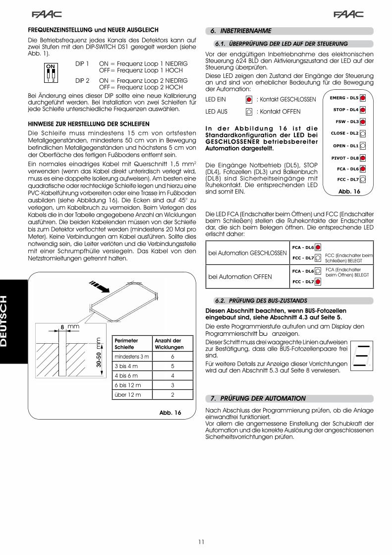
��
.6.. INBETRIEBNAHME
6.1.. ÜBERPRÜFUNG.DER.LED.AUF.DER.STEUERUNG
Abb. 16
6.2.. PRÜFUNG.DES.BUS-ZUSTANDS
Diesen Abschnitt beachten, wenn BUS-Fotozellen eingebaut sind, siehe Abschnitt 4.3 auf Seite 5.Die erste Programmierstufe aufrufen und am Display den Programmierschritt bu anzeigen.Dieser Schritt muss drei waagrechte Linien aufweisen zur Bestätigung, dass alle BUS-Fotozellenpaare frei sind.Für weitere Details zur Anzeige dieser Vorrichtungen wird auf den Abschnitt 5.� auf Seite 8 verwiesen.
.7.. PRÜFUNG.DER.AUTOMATION.
Nach Abschluss der Programmierung prüfen, ob die Anlage einwandfrei funktioniert.Vor allem die angemessene Einstellung der Schubkraft der Automation und die korrekte Auslösung der angeschlossenen Sicherheitsvorrichtungen prüfen.
FREQUENZEINSTELLUNG und NEUER AUSGLEICH
Die Betriebsfrequenz jedes Kanals des Detektors kann auf zwei Stufen mit den DIP-SWITCH DS� geregelt werden (siehe Abb. �).
DIP � ON = Frequenz Loop � NIEDRIG OFF= Frequenz Loop � HOCH
DIP � ON = Frequenz Loop � NIEDRIG OFF= Frequenz Loop � HOCHBei Änderung eines dieser DIP sollte eine neue Kalibrierung durchgeführt werden. Bei Installation von zwei Schleifen für jede Schleife unterschiedliche Frequenzen auswählen.
HINWEISE ZUR HERSTELLUNG DER SCHLEIFENDie Schleife muss mindestens �5 cm von ortsfesten Metallgegenständen, mindestens 50 cm von in Bewegung befindlichen Metallgegenständen und höchstens 5 cm von der Oberfläche des fertigen Fußbodens entfernt sein. Ein normales einadriges Kabel mit Querschnitt �,5 mm�
verwenden (wenn das Kabel direkt unterirdisch verlegt wird, muss es eine doppelte Isolierung aufweisen). Am besten eine quadratische oder rechteckige Schleife legen und hierzu eine PVC-Kabelführung vorbereiten oder eine Trasse im Fußboden ausbilden (siehe Abbildung �6). Die Ecken sind auf 45° zu verlegen, um Kabelbruch zu vermeiden. Beim Verlegen des Kabels die in der Tabelle angegebene Anzahl an Wicklungen ausführen. Die beiden Kabelenden müssen von der Schleife bis zum Detektor verflochtet werden (mindestens �0 Mal pro Meter). Keine Verbindungen am Kabel ausführen. Sollte dies notwendig sein, die Leiter verlöten und die Verbindungsstelle mit einer Schrumpfhülle versiegeln. Das Kabel von den Netzstromleitungen getrennt halten.
Vor der endgültigen Inbetriebnahme des elektronischen Steuerung 6�4 BLD den Aktivierungszustand der LED auf der Steuerung überprüfen.Diese LED zeigen den Zustand der Eingänge der Steuerung an und sind von erheblicher Bedeutung für die Bewegung der Automation:
LED EIN : Kontakt GESCHLOSSEN
LED AUS : Kontakt OFFEN
I n d e r A b b i l d u n g 1 6 i s t d i e Standardkonfiguration der LED bei GESCHLOSSENER betriebsbereiter Automation dargestellt.
Die Eingänge Notbetrieb (DL5), STOP (DL4), Fotozellen (DL�) und Balkenbruch (DL8) sind Sicherheitseingänge mit Ruhekontakt. Die entsprechenden LED sind somit EIN.
Die LED FCA (Endschalter beim Öffnen) und FCC (Endschalter beim Schließen) stellen die Ruhekontakte der Endschalter dar, die sich beim Belegen öffnen. Die entsprechende LED erlischt daher:
bei Automation GESCHLOSSEN FCC (Endschalter beim Schließen) BELEGT
bei Automation OFFENFCA (Endschalter beim Öffnen) BELEGT
Perimeter Schleife
Anzahl derWicklungen
mindestens � m 6
� bis 4 m 5
4 bis 6 m 4
6 bis �� m �
über �� m �
mm
mm
Abb. 16
DEUTSC
H

��
1 OFF2 OFF
Abb. 17
.8.. KONFIGURATIONEN.MASTER-SLAVE
Wenn in der Anlage zwei Schranken in Parallelbetrieb eingesetzt werden, die gleichzeitig beim Öffnen/Schließen des Durchgangs betätigt werden, ist eines der unten aufgeführten Anschlussdiagramme je nach zur Bewegung der Schranken steuerung Steuergeräten zu verwenden.
MASTER-Gerät ist die elektronische Karte, an die alle Impulsgeber und die Sicherheitsvorrichtungen angeschlossen sind.SLAVE-Gerät ist die elektronische Steuerkarte, die vom MASTER-Gerät über die Impulseingänge gesteuert wird. Die Sicherheitseingänge sind kurzgeschlossen.
a PROGRAMMIERUNG.DER.1..STUFE
LO = Cb PROGRAMMIERUNG.DER.3..STUFE
03 = Yc PROGRAMMIERUNG.DER.1..STUFE
LO = CU
DEUTSC
H

��
Die Programmierung der �. Stufe wird nur bei erweiterten individuellen Einstellungen der bereits eingespeicherten Steuerungslogiken eingesetzt.
Vor.Änderungen.in.dieser.Stufe.sicherstellen,.dass.die.Art.der.Schritte,.die.geändert.werden.soll,.und.ihr.Einfluss.auf.die.Automation.bekannt.sind.
Zum Aufrufen der PROGRAMMIERUNG DER �. STUFE die Taste F drücken, nicht loslassen, und die Taste + für zirka 10 Sekunden drücken. : Die Verwendung der Tasten F, + und – entspricht der der anderen beiden Programmierstufen.
PROGRAMMIERUNG DER 3. STUFE 10 Sek.
D. Funktion Einstellung
0 1 Durch die Aktivierung dieser Funktion erfolgt das automatische Schließen nach Ablauf der Pausenzeit.
Y = automatisches Schließenno = deaktiviert
02 Durch die Aktivierung dieser Funktion erfolgt der Betrieb mit zwei unterschiedlichen Eingängen: OPEN zum Öffnen und CLOSE zum Schließen.
Y = Betrieb mit zwei Eingängenno = deaktiviert
03Aktivierung der Erkennung der Stufen der Eingänge OPEN und CLOSE (Totmannschaltung) Die Steuerkarte erkennt die Stufe (wenn zum Beispiel OPEN aktiviert ist und STOP gedrückt wird, öffnet sich die Automation weiter, wenn STOP wieder losgelassen wird). Wenn 03 deaktiviert ist, sendet die Steuerkarte einen Impuls für eine Bewegung nur bei der Änderung des Eingangs.
Y = Erkennung der Stufeno = Erkennung der Änderung
des Zustands
04 Aktivierung der Öffnung mit TOTMANNSCHALTUNG Bei Loslassen der OPEN-Befehlseinrichtung wird der Betrieb blockiert
Y = einno = deaktiviert
05Durch die Aktivierung dieser Funktion stoppt der OPEN-Befehl die Öffnung während der Bewegung.Wenn der Parameter 06 auf no festgelegt ist, ist das System für die Öffnung bereit.Wenn der Paramete 06 auf Y “ festgelegt ist, ist das System für das Schließen bereit.
Y = blockiert beim Öffnenno = deaktiviert
06Durch die Aktivierung dieser Funktion kehrt der OPEN-Befehl die Bewegung um.Wenn die Parameter 05 und 06 auf no festgelegt sind, hat der OPEN-Befehl keine Wirkung während der Öffnung.
Y = kehrt beim Öffnen umno = deaktiviert
07Durch die Aktivierung dieser Funktion blockiert der OPEN-Befehl während der Pause den Betrieb. Wenn die Parameter 07 und 08 auf no festgelegt sind, bewirkt der OPEN-Befehl den erneu-ten Ablauf der Pausenzeit.
Y = blockiert in Pauseno = deaktiviert
08Durch die Aktivierung dieser Funktion bewirkt der OPEN-Befehl während der Pause das Schließen.Wenn die Parameter 07 und 08 auf no festgelegt sind, bewirkt der OPEN-Befehl den erneuten Ablauf der Pausenzeit.
Y = schließt in Pauseno = deaktiviert
09 Durch die Aktivierung dieser Funktion blockiert der OPEN-Befehl während des Schließens den Betrieb, ansonsten wird die Bewegungsrichtung umgekehrt.
Y = blockiert no = kehrt die
Bewegungsrichtung um
10 Aktivierung der Schließfunktion mit TOTMANNSCHALTUNG Bei Loslassen der CLOSE-Befehlseinrichtung wird der Betrieb blockiert.
Y = einno = deaktiviert
1 1 Durch die Aktivierung dieser Funktion hat der CLOSE-Befehl Vorrang vor dem OPEN-Befehl, anderenfalls hat der OPEN-Befehl Vorrang vor dem CLOSE-Befehl..
Y = einno = deaktiviert
12Durch die Aktivierung dieser Funktion bewirkt die CLOSE-Befehl das Schließen, wenn sie losgelassen wird. Solange der CLOSE-Befehl aktiv ist, bleibt die Einheit in der Funktion Vorblinken beim Schließen.
Y = schließt beim Loslassenno = schließt sofort
13Durch die Aktivierung dieser Funktion blockiert der CLOSE-Befehl während der Öffnung den Betrieb, ansonsten bewirkt der CLOSE-Befehl die Umkehrung sofort oder nach Abschluss des Öffnungsvorgangs (siehe auch Parameter 14)
Y = CLOSE blockiertno = CLOSE kehrt um
14Durch die Aktivierung dieser Funktion und wenn der Parameter 13 auf no, festgelegt ist, bewirkt der CLOSE-Befehl das sofortige Schließen nach Abschluss des Öffnungsvorgangs (speichert CLOSE ein). Wenn die Parameter 13 und 14 auf no festgelegt sind, bewirkt der CLOSE-Befehl das sofortige Schließen.
Y = schließt nach Abschluss des Öffnungsvorgangs
no = schließt sofort
15Durch die Aktivierung dieser Funktion bei durch einen STOP-Befehl blockiertem System bewirkt ein nachfolgender OPEN-Befehl die Bewegung in die andere Richtung. Wenn der Parameter 15 auf no festgelegt wurde, wird immer geschlossen.
Y = bewegt in die andere Richtung
no = schließt immer
16Durch die Aktivierung dieser Funktion beim Schließen blockieren die SICHERHEITSVORRICHTUNGEN BEIM SCHLIESSEN die Bewegung und geben sie beim Freiwerden wieder frei, ansonsten kehren sie die Bewegungsrichtung in Öffnen um.
Y = schließt beim Freiwerdenno = kehrt sofort um
17 Durch die Aktivierung dieser Funktion bewirken die SICHERHEITSVORRICHTUNGEN BEIM SCHLIESSEN bei Freiwerden das Schließen. (siehe auch Parameter 18).
Y = schließt beim Freiwerden von FSWno = deaktiviert
18 Durch die Aktivierung dieser Funktion und wenn der Parameter 17 auf Y, festgelegt wurde, wartet die Einheit den Abschluss des Öffnungsvorgangs ab, bevor der von den SICHERHEITSVORRICHTUNGEN BEIM SCHLIESSEN gesendete Schließbefehl ausgeführt wird.
Y = schließt nach Abschluss des Öffnungsvorgangs
no = deaktiviert
19Durch die Aktivierung dieser Funktion beim Schließen blockiert LOOP 2 die Bewegung und ermöglicht deren Aufnahme bei Freiwerden, ansonsten wird die Bewegungsrichtung sofort in Öffnen umgekehrt.
Y = Schließen bei Freiwerdenno = kehrt sofort um
20 Durch die Aktivierung dieser Funktion bewirkt LOOP 2 das Schließen bei Freiwerden (siehe auch Parameter 21).
Y = schließt bei Freiwerden von LOOP �no = deaktiviert
2 1 Durch die Aktivierung dieser Funktion und wenn der Parameter 20 auf Y , festgelegt wurde, wartet die Einheit den Abschluss des Öffnungsvorgangs ab, bevor der von LOOP 2 gesendete Schließbefehl ausgeführt wird.
Y = schließt nach Abschluss des Öffnungsvorgang
no = deaktiviert
22 Durch die Aktivierung dieser Funktion haben die Befehle von LOOP� Vorrang vor denen von LOOP�.
Y = einno = deaktiviert
.9.. PROGRAMMIERUNG.DER.3..STUFE
DEUTSC
H
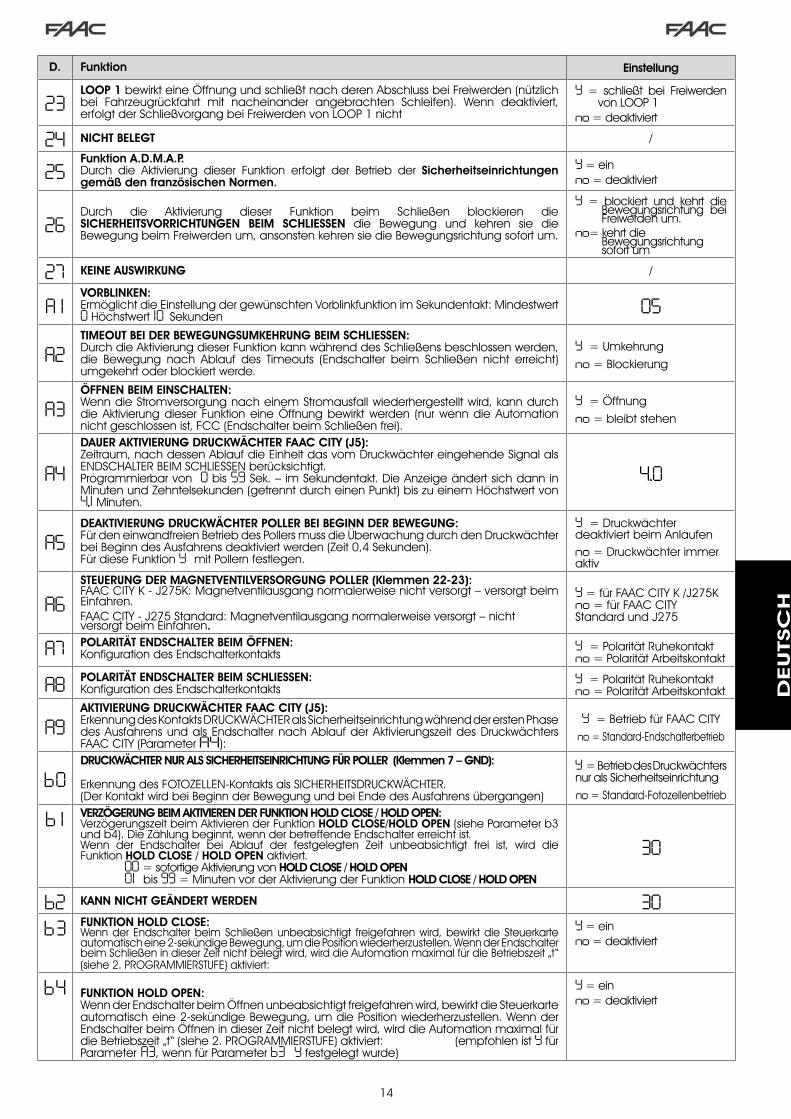
�4
D. Funktion Einstellung
23LOOP 1 bewirkt eine Öffnung und schließt nach deren Abschluss bei Freiwerden (nützlich bei Fahrzeugrückfahrt mit nacheinander angebrachten Schleifen). Wenn deaktiviert, erfolgt der Schließvorgang bei Freiwerden von LOOP � nicht
Y = schließt bei Freiwerden von LOOP �
no = deaktiviert
24 NICHT BELEGT /
25Funktion A.D.M.A.P.Durch die Aktivierung dieser Funktion erfolgt der Betrieb der Sicherheitseinrichtungen gemäß den französischen Normen.
Y = einno = deaktiviert
26Durch die Aktivierung dieser Funktion beim Schließen blockieren die SICHERHEITSVORRICHTUNGEN BEIM SCHLIESSEN die Bewegung und kehren sie die Bewegung beim Freiwerden um, ansonsten kehren sie die Bewegungsrichtung sofort um.
Y = blockiert und kehrt die Bewegungsrichtung bei Freiwerden um.
no= kehrt die Bewegungsrichtung sofort um
27 KEINE AUSWIRKUNG /
A 1VORBLINKEN:Ermöglicht die Einstellung der gewünschten Vorblinkfunktion im Sekundentakt: Mindestwert 0 Höchstwert 10 Sekunden
05
A2TIMEOUT BEI DER BEWEGUNGSUMKEHRUNG BEIM SCHLIESSEN:Durch die Aktivierung dieser Funktion kann während des Schließens beschlossen werden, die Bewegung nach Ablauf des Timeouts (Endschalter beim Schließen nicht erreicht) umgekehrt oder blockiert werde.
Y = Umkehrungno = Blockierung
A3ÖFFNEN BEIM EINSCHALTEN:Wenn die Stromversorgung nach einem Stromausfall wiederhergestellt wird, kann durch die Aktivierung dieser Funktion eine Öffnung bewirkt werden (nur wenn die Automation nicht geschlossen ist, FCC (Endschalter beim Schließen frei).
Y = Öffnungno = bleibt stehen
A4DAUER AKTIVIERUNG DRUCKWÄCHTER FAAC CITY (J5):Zeitraum, nach dessen Ablauf die Einheit das vom Druckwächter eingehende Signal als ENDSCHALTER BEIM SCHLIESSEN berücksichtigt.Programmierbar von 0 bis 59 Sek. – im Sekundentakt. Die Anzeige ändert sich dann in Minuten und Zehntelsekunden (getrennt durch einen Punkt) bis zu einem Höchstwert von 4,1 Minuten.
4.0
A5DEAKTIVIERUNG DRUCKWÄCHTER POLLER BEI BEGINN DER BEWEGUNG: Für den einwandfreien Betrieb des Pollers muss die Überwachung durch den Druckwächter bei Beginn des Ausfahrens deaktiviert werden (Zeit 0,4 Sekunden).Für diese Funktion Y mit Pollern festlegen.
Y = Druckwächter deaktiviert beim Anlaufen no = Druckwächter immer aktiv
A6STEUERUNG DER MAGNETVENTILVERSORGUNG POLLER (Klemmen 22-23):FAAC CITY K - J�75K: Magnetventilausgang normalerweise nicht versorgt – versorgt beim Einfahren.FAAC CITY - J�75 Standard: Magnetventilausgang normalerweise versorgt – nicht versorgt beim Einfahren.
Y = für FAAC CITY K /J�75K no = für FAAC CITY Standard und J�75
A7 POLARITÄT ENDSCHALTER BEIM ÖFFNEN:Konfiguration des Endschalterkontakts
Y = Polarität Ruhekontaktno = Polarität Arbeitskontakt
A8 POLARITÄT ENDSCHALTER BEIM SCHLIESSEN:Konfiguration des Endschalterkontakts
Y = Polarität Ruhekontaktno = Polarität Arbeitskontakt
A9AKTIVIERUNG DRUCKWÄCHTER FAAC CITY (J5):Erkennung des Kontakts DRUCKWÄCHTER als Sicherheitseinrichtung während der ersten Phase des Ausfahrens und als Endschalter nach Ablauf der Aktivierungszeit des Druckwächters FAAC CITY (Parameter A4):
Y = Betrieb für FAAC CITYno = Standard-Endschalterbetrieb
b0DRUCKWÄCHTER NUR ALS SICHERHEITSEINRICHTUNG FÜR POLLER (Klemmen 7 – GND):
Erkennung des FOTOZELLEN-Kontakts als SICHERHEITSDRUCKWÄCHTER.(Der Kontakt wird bei Beginn der Bewegung und bei Ende des Ausfahrens übergangen)
Y = Betrieb des Druckwächters nur als Sicherheitseinrichtungno = Standard-Fotozellenbetrieb
b 1 VERZÖGERUNG BEIM AKTIVIEREN DER FUNKTION HOLD CLOSE / HOLD OPEN:Verzögerungszeit beim Aktivieren der Funktion HOLD CLOSE/HOLD OPEN (siehe Parameter b� und b4). Die Zählung beginnt, wenn der betreffende Endschalter erreicht ist.Wenn der Endschalter bei Ablauf der festgelegten Zeit unbeabsichtigt frei ist, wird die Funktion HOLD CLOSE / HOLD OPEN aktiviert. 00 = sofortige Aktivierung von HOLD CLOSE / HOLD OPEN 01 bis 99 = Minuten vor der Aktivierung der Funktion HOLD CLOSE / HOLD OPEN
30
b2 KANN NICHT GEÄNDERT WERDEN 30b3 FUNKTION HOLD CLOSE:
Wenn der Endschalter beim Schließen unbeabsichtigt freigefahren wird, bewirkt die Steuerkarte automatisch eine �-sekündige Bewegung, um die Position wiederherzustellen. Wenn der Endschalter beim Schließen in dieser Zeit nicht belegt wird, wird die Automation maximal für die Betriebszeit „t“ (siehe �. PROGRAMMIERSTUFE) aktiviert:
Y = einno = deaktiviert
b4 FUNKTION HOLD OPEN:Wenn der Endschalter beim Öffnen unbeabsichtigt freigefahren wird, bewirkt die Steuerkarte automatisch eine �-sekündige Bewegung, um die Position wiederherzustellen. Wenn der Endschalter beim Öffnen in dieser Zeit nicht belegt wird, wird die Automation maximal für die Betriebszeit „t“ (siehe �. PROGRAMMIERSTUFE) aktiviert: (empfohlen ist Y für Parameter A3, wenn für Parameter b3 Y festgelegt wurde)
Y = einno = deaktiviert
DEUTSC
H

�5
9.1.. INDIVIDUELLE.EINSTELLUNG.DER.STEUERUNGSLOGIK
Die Werte der Programmierung der �. Stufe hängen von der in der ersten Programmierstufe ausgewählten Steuerungslogik ab.
Die �. Programmierstufe dient der individuellen Einstellung einer der auswählbaren Steuerungslogiken, falls ein spezielles Verhalten der Anlage erforderlich ist.
Damit die Änderung eines oder mehrerer Parameter der �. Programmierstufe, mit denen die festgelegte Betriebslogik individuell eingestellt wird, wirksam wird, sind folgende Schritte auszuführen:
Eine der Basissteuerungslogiken auswählen, die den Anforderungen am besten entspricht.Die �. Programmierstufe aufrufen und die gewünschten Parameter ändern.Die �. Stufe beenden und in der �. Stufe die Logik Cu auswählen.
Mit der Logik Cu werden die in der �. Stufe vorgenommenen Änderungen wirksam.
In der nachfolgenden Tabelle sind die Defaultparameter für die Steuerungslogiken aufgeführt.
�.
�.
�.
Schritt A A1 E P PA Cn CA rb C
0 1 Y Y N N Y N Y Y N02 N N N Y Y Y Y Y Y03 N N N N N N N Y N04 N N N N N N N N Y05 N N Y N N N N N N06 N N Y N N N N N N07 N N N N N N N N N08 N N N N N N N N N09 N N N N N N N N N10 N N N N N N N N Y1 1 N N N N N N N N N12 N N N Y Y N N N N13 N N N N N N N N N14 N N N Y Y Y Y N N15 N N N N N N N N N16 N N N Y Y N N N N17 N Y N N N N N N N18 N Y N N N N N N N19 N N N Y Y N N N N20 N Y N Y Y Y Y N N2 1 N Y N Y Y Y Y N N22 N N N N N Y Y N N23 N N N Y Y N N N N24 N N N N N N N N N25 N N N N N N N N N26 N N N N N N N N N
.10.. VOREINSTELLUNGSWERTE
In der nachfolgenden Tabelle sind die Werte der Schritte für jede Programmierstufe je nach ausgewählter Voreinstellung aufgeführt
1. STUFE
2. STUFE
b5 MAGNETVENTILSTEUERUNG POLLER:Funktion für J�75 / J�75K auf Y festlegen.Funktion für FAAC CITY / FAAC CITY K auf no festlegen.
Y = für J�75 / J�75Kno= FAAC CITY / FAAC CITY K
b6 STEUERUNGSLOGIK NOTEINGANG:Beim Aktivieren (EIN) dieser Funktion steuert der Noteingang eine Schließbewegung, die bis zur Wiederherstellung des Kontakts beibehalten wird.Wenn die Funktion deaktiviert wird (AUS), steuert der Noteingang eine Öffnungsbewegung, die bis zur Wiederherstellung des Kontakts beibehalten wird.
Y = EINno = AUS
St STATUS DER AUTOMATION:Beenden der Programmierung, Einspeicherung der Daten und Anzeige des Zustands des Tors (siehe Abschn. 5.�.).
D. Funktion Einstellung
Default FAAC1
FAAC VORBEHALTEN
Default FAAC CITY
Default FAAC CITY K
Default J275
Default J275K
dF Voreinstellung 0 1 02 03 04 05 06bu BUS
Lo Steuerungslogik E A1 rb rb rb rbPA Pause 20 20 30 30 30 30FO Schubkraft 50 50 50 50 50 50L 1 Loop � no no no no no noL2 Loop � no no no no no noH 1 Loop � no no no no no noH 2 Loop � no no no no no noS 1 Empfindlichkeit 05 05 05 05 05 05S2 Empfindlichkeit 05 05 05 05 05 05
bo boost Y Y Y Y Y YPF Vorblinken no CL no no no noSC langsames Schließen no no no no no notr Verlangsamung 03 03 0 1 0 1 0 1 0 1t Timeout 20 20 12 12 12 12FS Failsafe no no no no no noo 1 Ausgang � 00 16 15 15 15 15P 1 Polarität � no no no no no noo2 Ausgang � 03 17 14 14 03 03P2 Polarität � no no no no no noo3 Ausgang � 0 1 0 1 0 1 0 1 0 2 0 2P3 Polarität � no no no no no noo4 Ausgang 4 00 00 00 00 00 00P4 Polarität 4 no no no no no noA5 Service no no no no no nonc Zyklen �. 00 00 00 00 00 00nC Zyklen �. 0 1 0 1 0 1 0 1 0 1 0 1h 1 Verweildauer no no no no no noh2 Verweildauer no no no no no no
Default FAAC1
FAAC VORBEHALTEN
Default FAAC CITY
Default FAAC CITY K
Default J275
Default J275K
DEUTSC
H
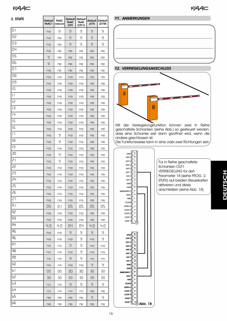
�6
____________________________________________________
_____________________________________________________
________________________________________________________________________________________________________
1918
1617
1514
1213
1011
89
67
45
23
1
OPEN A
STOP
LOOP 1
LOOP 2
LOOP 2
LOOP 1
CLOSE
FSW
EMERGENCY
OUT 1
OUT 2
OUT 4
OUT 3
GND
GND
GND
+24 V
+24 V
OUT 3
J119
1816
1715
1412
1310
118
96
74
52
31
OPEN A
STOP
LOOP 1
LOOP 2
LOOP 2
LOOP 1
CLOSE
FSW
EMERGENCY
OUT 1
OUT 2
OUT 4
OUT 3
GND
GND
GND
+24 V
+24 V
OUT 3
J119
1816
1715
1412
1310
118
96
74
52
31
OPEN A
STOP
LOOP 1
LOOP 2
LOOP 2
LOOP 1
CLOSE
FSW
EMERGENCY
OUT 1
OUT 2
OUT 4
OUT 3
GND
GND
GND
+24 V
+24 V
OUT 3
J1
.11.. ANMERKUNGEN
.12.. VERRIEGELUNGSANSCHLUSS
Mit der Verriegelungsfunktion können zwei in Reihe geschaltete Schranken (siehe Abb.) so gesteuert werden, dass eine Schranke erst dann geöffnet wird, wenn die andere geschlossen ist.Die Funktionsweise kann in eine oder zwei Richtungen sein
Abb. 18
08 no no no no no no09 no no no no no no10 no no no no no no1 1 no no no no no no12 no no no no no no13 no no no no no no14 no no no no no no15 no no no no no no16 no no no no no no17 no Y no no no no18 no Y no no no no19 no no no no no no20 no Y no no no no2 1 no Y no no no no22 no no no no no no23 no no no no no no24 no no no no no no25 no no no no no no26 no no no no no no27 no no no no no noA 1 05 0 1 05 05 05 05A2 no no no no no noA3 no no no no no noA4 4 .0 4 .0 04 04 4 .0 4 .0A5 no no Y Y Y YA6 no no no Y no YA7 no no Y Y no noA8 no no no Y no noA9 no no Y Y no nob0 no no no no Y Yb 1 00 00 30 30 30 30b2 30 30 30 30 30 30b3 no no Y Y Y Yb4 no no no no no nob5 no no no no Y Yb6 no no no no no no
0 1 no Y Y Y Y Y02 no no Y Y Y Y03 no no Y Y Y Y04 no no no no no no05 Y no no no no no06 Y no no no no no07 no no no no no no
Default FAAC1
FAAC VORBEHALTEN
Default FAAC CITY
Default FAAC CITY K
Default J275
Default J275K
Für in Reihe geschaltete Schranken OUT� VERRIEGELUNG für den Parameter �8 (siehe PROG. �. STUFE) auf beiden Steuerkarten aktivieren und diese anschließen (siehe Abb. �8)
3. STUFE
DEUTSC
H

�7
Tab. 1/b
Tab. 1/a
LOGIK “A” IMPULSE
STATUS DER AUTOMATION OPEN A CLOSE STOP FSW LOOP 1 LOOP 2
GESCHLOSSENöffnet und schließt nach Ablauf der
Pausenzeitkeine Auswirkung
keine Auswirkung (Öffnung
gehemmt)keine Auswirkung
öffnet und schließt nach Ablauf der
Pausenzeitkeine Auswirkung
BEIM ÖFFNEN keine Auswirkungsofortige
Richtungsumkehrung beim Schließen
blockiert den Betrieb keine Auswirkung keine Auswirkung keine Auswirkung
OFFEN IN PAUSE erneuter Ablauf Pausenzeit schließt blockiert den
Betrieb
erneuter Ablauf Pausenzeit(Schließen gehemmt)
erneuter Ablauf Pausenzeit
erneuter Ablauf Pausenzeit(Schließen gehemmt)
BEIM SCHLIESSENsofortige
Richtungsumkehrung beim Öffnen
keine Auswirkung blockiert den Betrieb
sofortige Richtungsumkehrung
beim Öffnen
sofortige Richtungsumkehrung
beim Öffnen
sofortige Richtungsumkehrung
beim Öffnen
GESPERRT schließt schließtkeine Auswirkung
(Öffnen und Schließen gehemmt)
keine Auswirkung (Schließen gehemmt)
öffnet und schließt nach Ablauf der
Pausenzeit
keine Auswirkung (Schließen gehemmt)
LOGIK “A1” IMPULSE
STATUS DER AUTOMATION OPEN A CLOSE STOP FSW LOOP 1 LOOP 2
GESCHLOSSENöffnet und schließt nach Ablauf der
Pausenzeitkeine Auswirkung
keine Auswirkung (Öffnung
gehemmt)keine Auswirkung
öffnet und schließt nach Ablauf der
Pausenzeitkeine Auswirkung
BEIM ÖFFNEN keine Auswirkungsofortige
Richtungsumkehrung beim Schließen
blockiert den Betrieb
schließt sofort nach
Abschluss des Öffnungsvorgangs
keine Auswirkungschließt
sofort nach Abschluss des
Öffnungsvorgangs
OFFEN IN PAUSE erneuter Ablauf Pausenzeit schließt blockiert den
Betrieb schließt erneuter Ablauf Pausenzeit schließt
BEIM SCHLIESSENsofortige
Richtungsumkehrung beim Öffnen
keine Auswirkung blockiert den Betrieb
sofortige Richtungsumkehrung
beim Öffnen
Sofortige Richtungsumkehrung
beim Öffnen, schließt nach
Ablauf der Pausenzeit
kehrt sofort in Öffnungsbewe-
gung um, schließt erneut nach
abgeschlossener Öffnung
GESPERRT schließt schließtkeine Auswirkung
(Öffnen und Schließen gehemmt)
keine Auswirkung (Schließen gehemmt)
öffnet und schließt nach Ablauf der
Pausenzeit
keine Auswirkung (Schließen gehemmt)
LOGIK “E” IMPULSE
STATUS DER AUTOMATION OPEN A CLOSE STOP FSW LOOP 1 LOOP 2
GESCHLOSSEN öffnet keine Auswirkungkeine Auswirkung
(Öffnung gehemmt)
keine Auswirkung öffnet keine Auswirkung
BEIM ÖFFNEN blockiert den Betrieb
sofortige Richtungsumkehrung beim Schließen
blockiert den Betrieb keine Auswirkung keine Auswirkung keine Auswirkung
OFFEN schließt schließtkeine Auswirkung
(Schließen gehemmt)
keine Auswirkung (Schließen gehemmt)
schließtkeine Auswirkung
(Schließen gehemmt)
BEIM SCHLIESSENsofortige
Richtungsumkehrung beim Öffnen
keine Auswirkung blockiert den Betrieb
sofortige Richtungsumkehrung
beim Öffnen
sofortige Richtungsumkehrung
beim Öffnen
sofortige Richtungsumkehrung
beim Öffnen
GESPERRT schließt schließtkeine Auswirkung
(Öffnen und Schließen gehemmt)
keine Auswirkung (Schließen gehemmt)
öffnetkeine Auswirkung
(Schließen gehemmt)
In Klammern sind die Auswirkungen auf die anderen Eingänge mit aktivem Impuls angegeben
.13.. TABELLEN.DER.STEUERUNGSLOGIKEN
Tab. 1/c
DEUTSC
H

�8
Tab. 1/d
Tab. 1/e
Tab. 1/f
LOGIK “P” IMPULSE
STATUS DER AUTOMATION OPEN A CLOSE STOP FSW LOOP 1 LOOP 2
GESCHLOSSEN öffnet keine Auswirkungkeine Auswirkung
(Öffnung gehemmt)
keine Auswirkungöffnet und schließt nach Abschluss des Öffnungsvorgangs,
wenn freikeine Auswirkung
BEIM ÖFFNEN keine Auswirkungschließt
sofort nach Abschluss des
Öffnungsvorgangs
blockiert den Betrieb keine Auswirkung keine Auswirkung
schließt sofort nach
Abschluss des Öffnungsvorgangs
OFFENkeine Auswirkung
(Schließen gehemmt)
schließtkeine Auswirkung
(Schließen gehemmt)
keine Auswirkung (Schließen gehemmt)
Hemmt das Schließen schließt
BEIM SCHLIESSENsofortige
Richtungsumkehrung beim Öffnen
keine Auswirkung blockiert den Betrieb
blockiert und schließt weiter bei Freiwerden
sofortige Richtungsumkehrung beim Öffnen und
schließt nach dem Öffnen, wenn frei
blockiert und schließt weiter bei Freiwerden
GESPERRT öffnet schließtkeine Auswirkung
(Öffnen und Schließen gehemmt)
keine Auswirkung (Schließen gehemmt)
öffnet und schließt nach Abschluss des Öffnungsvorgangs,
wenn frei
keine Auswirkung (Schließen gehemmt)
In Klammern sind die Auswirkungen auf die anderen Eingänge mit aktivem Impuls angegeben
LOGIK “PA” IMPULSE
STATUS DER AUTOMATION OPEN A CLOSE STOP FSW LOOP 1 LOOP 2
GESCHLOSSENöffnet und schließt nach Ablauf der
Pausenzeitkeine Auswirkung
keine Auswirkung (Öffnung
gehemmt)keine Auswirkung
öffnet und schließt nach Abschluss des Öffnungsvorgangs,
wenn freikeine Auswirkung
BEIM ÖFFNEN keine Auswirkungschließt
sofort nach Abschluss des
Öffnungsvorgangs
blockiert den Betrieb keine Auswirkung keine Auswirkung
schließt sofort nach
Abschluss des Öffnungsvorgangs
OFFEN IN PAUSE erneuter Ablauf Pausenzeit schließt blockiert den
Betrieb
erneuter Ablauf Pausenzeit(Schließen gehemmt)
erneuter Ablauf Pausenzeit schließt
BEIM SCHLIESSENsofortige
Richtungsumkehrung beim Öffnen
keine Auswirkung blockiert den Betrieb
blockiert und schließt weiter bei Freiwerden
sofortige Richtungsumkehrung beim Öffnen und
schließt nach dem Öffnen, wenn frei
blockiert und schließt weiter bei Freiwerden
GESPERRTöffnet und schließt nach Ablauf der
Pausenzeitschließt
keine Auswirkung (Öffnen und Schließen gehemmt)
keine Auswirkung (Schließen gehemmt)
öffnet und schließt nach Abschluss des Öffnungsvorgangs,
wenn frei
keine Auswirkung (Schließen gehemmt)
LOGIK “Cn” IMPULSE
STATUS DER AUTOMATION OPEN A CLOSE STOP FSW LOOP 1 LOOP 2
GESCHLOSSEN öffnet keine Auswirkungkeine Auswirkung
(Öffnung gehemmt)
keine Auswirkung öffnet keine Auswirkung
BEIM ÖFFNEN keine Auswirkungschließt
sofort nach Abschluss des
Öffnungsvorgangs
blockiert den Betrieb keine Auswirkung keine Auswirkung
schließt sofort nach
Abschluss des Öffnungsvorgangs
OFFENkeine Auswirkung
(Schließen gehemmt)
schließtkeine Auswirkung
(Schließen gehemmt)
keine Auswirkung (Schließen gehemmt)
keine Auswirkung schließt
BEIM SCHLIESSENsofortige
Richtungsumkehrung beim Öffnen
keine Auswirkung blockiert den Betrieb
bewirkt die Richtungsumkehrung
beim Öffnen und schließt nach Ablauf
der Pausenzeit
sofortige Richtungsumkehrung
beim Öffnen
sofortige Richtungsumkehrung
beim Öffnen
GESPERRT öffnet schließtkeine Auswirkung
(Öffnen und Schließen gehemmt)
keine Auswirkung (Schließen gehemmt)
öffnetkeine Auswirkung
(Schließen gehemmt)
DEUTSC
H
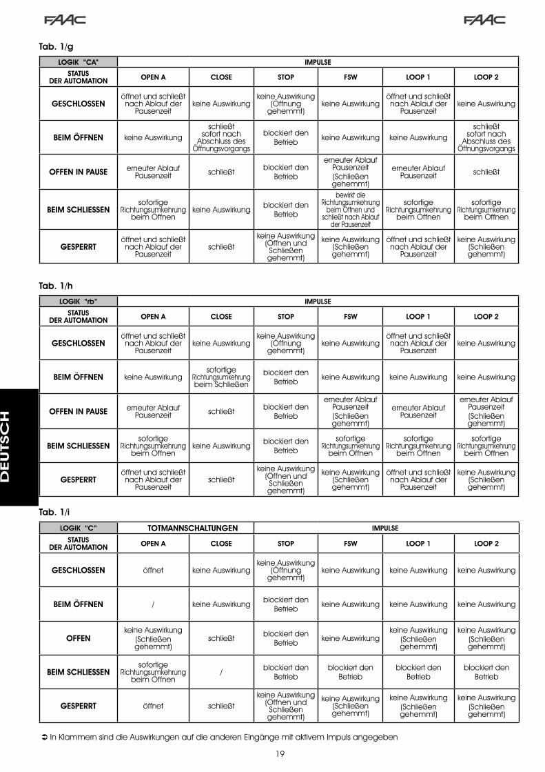
�9
Tab. 1/i
Tab. 1/g
Tab. 1/h
LOGIK “CA” IMPULSE
STATUS DER AUTOMATION OPEN A CLOSE STOP FSW LOOP 1 LOOP 2
GESCHLOSSENöffnet und schließt nach Ablauf der
Pausenzeitkeine Auswirkung
keine Auswirkung (Öffnung
gehemmt)keine Auswirkung
öffnet und schließt nach Ablauf der
Pausenzeitkeine Auswirkung
BEIM ÖFFNEN keine Auswirkungschließt
sofort nach Abschluss des
Öffnungsvorgangs
blockiert den Betrieb keine Auswirkung keine Auswirkung
schließt sofort nach
Abschluss des Öffnungsvorgangs
OFFEN IN PAUSE erneuter Ablauf Pausenzeit schließt blockiert den
Betrieb
erneuter Ablauf Pausenzeit(Schließen gehemmt)
erneuter Ablauf Pausenzeit schließt
BEIM SCHLIESSENsofortige
Richtungsumkehrung beim Öffnen
keine Auswirkung blockiert den Betrieb
bewirkt die Richtungsumkehrung
beim Öffnen und schließt nach Ablauf
der Pausenzeit
sofortige Richtungsumkehrung
beim Öffnen
sofortige Richtungsumkehrung
beim Öffnen
GESPERRTöffnet und schließt nach Ablauf der
Pausenzeitschließt
keine Auswirkung (Öffnen und Schließen gehemmt)
keine Auswirkung (Schließen gehemmt)
öffnet und schließt nach Ablauf der
Pausenzeit
keine Auswirkung (Schließen gehemmt)
LOGIK “rb” IMPULSE
STATUS DER AUTOMATION OPEN A CLOSE STOP FSW LOOP 1 LOOP 2
GESCHLOSSENöffnet und schließt nach Ablauf der
Pausenzeitkeine Auswirkung
keine Auswirkung (Öffnung
gehemmt)keine Auswirkung
öffnet und schließt nach Ablauf der
Pausenzeitkeine Auswirkung
BEIM ÖFFNEN keine Auswirkungsofortige
Richtungsumkehrung beim Schließen
blockiert den Betrieb keine Auswirkung keine Auswirkung keine Auswirkung
OFFEN IN PAUSE erneuter Ablauf Pausenzeit schließt blockiert den
Betrieb
erneuter Ablauf Pausenzeit(Schließen gehemmt)
erneuter Ablauf Pausenzeit
erneuter Ablauf Pausenzeit(Schließen gehemmt)
BEIM SCHLIESSENsofortige
Richtungsumkehrung beim Öffnen
keine Auswirkung blockiert den Betrieb
sofortige Richtungsumkehrung
beim Öffnen
sofortige Richtungsumkehrung
beim Öffnen
sofortige Richtungsumkehrung
beim Öffnen
GESPERRTöffnet und schließt nach Ablauf der
Pausenzeitschließt
keine Auswirkung (Öffnen und Schließen gehemmt)
keine Auswirkung (Schließen gehemmt)
öffnet und schließt nach Ablauf der
Pausenzeit
keine Auswirkung (Schließen gehemmt)
In Klammern sind die Auswirkungen auf die anderen Eingänge mit aktivem Impuls angegeben
LOGIK “C” TOTMANNSCHALTUNGEN IMPULSE
STATUS DER AUTOMATION OPEN A CLOSE STOP FSW LOOP 1 LOOP 2
GESCHLOSSEN öffnet keine Auswirkungkeine Auswirkung
(Öffnung gehemmt)
keine Auswirkung keine Auswirkung keine Auswirkung
BEIM ÖFFNEN / keine Auswirkung blockiert den Betrieb keine Auswirkung keine Auswirkung keine Auswirkung
OFFENkeine Auswirkung
(Schließen gehemmt)
schließt blockiert den Betrieb keine Auswirkung
keine Auswirkung(Schließen gehemmt)
keine Auswirkung(Schließen gehemmt)
BEIM SCHLIESSENsofortige
Richtungsumkehrung beim Öffnen
/ blockiert den Betrieb
blockiert den Betrieb
blockiert den Betrieb
blockiert den Betrieb
GESPERRT öffnet schließtkeine Auswirkung
(Öffnen und Schließen gehemmt)
keine Auswirkung (Schließen gehemmt)
keine Auswirkung(Schließen gehemmt)
keine Auswirkung(Schließen gehemmt)
DEUTSC
H

�
ÍNDICE1....ADVERTENCIAS.............................................................................................................................................3
2....CARACTERÍSTICAS.TÉCNICAS.......................................................................................................................3
3....LAYOUT.Y.COMPONENTES.624BLD...............................................................................................................3
3.1.Descripción.de.los.componentes.........................................................................................................3
4....CONEXIONES.ELÉCTRICAS............................................................................................................................4
4.1...Regleta.de.bornes.J1.-.Accesorios.(Fig..2)..........................................................................................4
4.2...Conexión.fotocélulas.de.RELÉ.y.dispositivos.de.seguridad.con.contacto.“N.C.”...........................................5
4.3...Conexión.fotocélulas.BUS....................................................................................................................5
4.4...Regleta.de.bornes.J2.-.Motor,.destellador.y.ventilador.(fig..2)..........................................................6
4.5...Conector.J8.-.Condensador.motor..(Fig..2)........................................................................................6
4.6...Regleta.de.bornes.J9.-.Alimentación.(Fig..2)......................................................................................6
4.7...Conectores.J3,.J5.-.Acoplamiento.rápido.final.de.carrera.de.apertura.y.de.cierre..(Fig..2)...........6
4.8...Conector.J6.-.Sensor.de.empuje.barra.(Fig..2)....................................................................................6
4.9...Detector.frecuencia.DS1.(Fig..1)..................................................................................................................... 6
4.10.Conector.J4.-.Acoplamiento.Minidec,.Decoder.y.RP................................................................................. 6
5....PROGRAMACIÓN.........................................................................................................................................6
5.1...PROGRAMACIÓN.DE.1°.NIVEL...............................................................................................................6
5.2...Modificación.de.la.pre-configuración................................................................................................8
5.3...Configuración.y.control.del.sistema.BUS............................................................................................8
5.4...PROGRAMACIÓN.DE.2°.NIVEL...............................................................................................................9
5.5...Configuración.Loop.Detector.Incorporado........................................................................................10
6....PUESTA.EN.FUNCIONAMIENTO......................................................................................................................11
6.1...Comprobaciones.de.los.DIODOS.tarjeta............................................................................................11
6.2...Comprobación.del.estado.del.BUS.....................................................................................................11
7....PRUEBA.DEL.AUTOMATISMO.........................................................................................................................11
8....CONFIGURACIONES.MASTER-SLAVE.............................................................................................................12
9....PROGRAMACIÓN.DE.3°.NIVEL......................................................................................................................13
9.1...Programmazione.della.logica.di.pre-setting......................................................................................15
10..VALORES.DE.LAS.PRE-CONFIGURACIONES....................................................................................................15
11..NOTAS..........................................................................................................................................................16
12..CONEXIÓN.INTERBLOQUEO..........................................................................................................................16
13..TABLAS.LÓGICAS.DE.FUNCIONAMIENTO.......................................................................................................17
ESPA
ÑO
L
�
DECLARACIÓN CE DE CONFORMIDAD
Fabbricante: FAAC S.p.A.
Dirección: Via Calari, �0 - 40069 Zola Predosa BOLOGNA - ITALIA
Declara que: El equipo electrónico 6�4BLD
• cumple con los requisitos esenciales de seguridad de las siguientes directivas CEE:
�006/95/CE directiva de Baja Tensión �004/�08/CE directiva de Compatibilidad Electromagnética
Nota adicional: Este producto ha sido sometido a ensayos en una configuración típica homogénea (todos productos de fabricación FAAC S.p.A.)
Bologna, 0� de enero de �0�0
El Administrador Delegado A. Marcellani
ADVERTENCIAS PARA EL INSTALADOROBLIGACIONES GENERALES EN MATERIA DE SEGURIDAD
1) ¡ATENCIÓN!Paralaseguridaddelaspersonasessumamenteimportanteseguiratentamenteestasinstrucciones.Unainstalaciónincorrectaounautilizacióninadecuadadelproductopuedencausargravesdañosalaspersonas.
2) Leadetenidamentelasinstruccionesantesdeempezarlainstalacióndelproducto.
3) Losmaterialesdelembalaje(plástico,poliestireno,etc.)debenman-tenerse fuera del alcance de los niños, ya que constituyen fuentespotencialesdepeligro.
4) Guardelasinstruccionesparafuturasconsultas.
5) Este producto se ha diseñado y fabricado exclusivamente para elusoquese indicaenestemanual.Cualquierotrousoquenohayasidoexpresamenteprevistopodríaperjudicarel funcionamientodelproductoy/orepresentarunafuentedepeligro.
6) FAACdeclina toda responsabilidadderivadadeunuso indebidoodiversoalusoparaelqueelautomatismosehafabricado.
7) Noinstaleelaparatoenunambienteexplosivo:lapresenciadegasohumosinflamablesconstituyeungravepeligroparalaseguridad.
8) LoselementosmecánicosdebenserconformesaloestablecidoporlasNormasEN12604yEN12605.
Para los países extracomunitarios, además de las referencias a lalegislaciónnacional,paraobtenerunniveldeseguridadadecuado,debenseguirselasNormativasindicadasanteriormente.
9) FAACnosehaceresponsabledelincumplimientodelabuenatécnicaaplicadaalaconstruccióndeloscerramientosamotorizar,asícomodelasdeformacionesprovocadasduranteeluso.
10) LainstalacióndeberealizarsedeacuerdoconlasNormasEN12453yEN12445.
Para los países extracomunitarios, además de las referencias a lalegislaciónnacional,paraobtenerunniveldeseguridadadecuado,debenseguirselasNormativasindicadasanteriormente.
11) Desconecte la alimentación eléctrica antes de realizar cualquierintervenciónenelequipo.
12) Coloqueen la reddealimentacióndelautomatismoun interruptoromnipolarcondistanciadeaperturadeloscontactosigualosuperiora3mm.Serecomiendautilizaruninterruptormagnetotérmicode6Aconinterrupciónomnipolar.
13) Compruebequeencimadelequipohayaun interruptordiferencialconunumbralde0,03A.
14) Compruebequelainstalacióndetierraestécorrectamenterealizadayconecteaestalaspartesmetálicasdelcierre.
15) El automatismo dispone de un dispositivo de seguridad antiaplas-tamientoformadoporuncontroldepar.Noobstante,esnecesariocomprobarelumbraldeintervencióndeacuerdoconloprevistoenlasNormasindicadasenelpunto10.
16) Los dispositivos de seguridad (norma EN 12978) permiten protegerposiblesáreasdepeligrodeRiesgosmecánicosdemovimiento,comoporejemplo,aplastamiento,arrastre,corte.
17) Paracadaequipo se recomiendautilizarpor lomenosuna señali-zaciónluminosa(ej.FAACLIGHT)asícomouncarteldeseñalizaciónadecuadamentefijadoalaestructuradelbastidor,ademásdelosdispositivosindicadosenelpunto“16”.
18) FAACdeclinatodaresponsabilidadrelativaalaseguridadyalbuenfuncionamientodelautomatismosiseutilizanenelequipocompo-nentesquenohayansidofabricadosporFAAC.
19) Para el mantenimiento, utilice exclusivamente piezas originalesFAAC.
20) Nolleveacaboningunamodificaciónenloscomponentesqueformanpartedelsistemadeautomatismo.
21) El instaladordebeproporcionartodala informaciónrelativaalfun-cionamientomanualdelsistemaencasodeemergenciayentregaralusuariodelequipoelmanualdeadvertenciasqueseadjuntaalproducto.
22) Nopermitaqueniñosopersonassedetengancercadelproductodurantesufuncionamiento.
23) Mantengafueradelalcancedelosniñoslostelemandosocualquierotroemisorde impulso,paraevitarqueelautomatismopuedaseraccionadoinvoluntariamente.
24) Elpasosóloesposiblecuandoelautomatismoestáparado.
25) Elusuarionodebeporningúnmotivointentarrepararomodificarelproducto,debedirigirseunicámenteapersonalcualificado.
26) Mantenimiento: compruebe por lo menos semestralmente que elequipo funcione correctamente, prestando especial atención alaeficienciade losdispositivosdeseguridad(incluida,dondeestéprevisto,lafuerzadeempujedeloperador)ydedesbloqueo.
27) Todoloquenoestéprevistoexpresamenteenlaspresentesinstruc-cionesdebeentendersecomonopermitido.
ESPA
ÑO
L

�
.1.. ADVERTENCIAS
Atención: Antes de efectuar cualquier tipo de intervención en el equipo electrónico (conexiones, mantenimiento) quite siempre la alimentación eléctrica
- Coloque antes de la instalación un interruptor magnetotérmico diferencial con un adecuado umbral de intervención.- Conecte el cable de tierra al correspondiente borne previsto en el conector J9 del equipo (véase fig.2).- Separe siempre los cables de alimentación de los cables de mando y de seguridad (pulsador, receptor, fotocélulas, etc.).
Para evitar cualquier interferencia eléctrica utilice vainas separadas o un cable blindado (con el blindaje conectado a masa).
EQUIPO ELECTRÓNICO 624 BLD
.3.. LAYOUT.Y.COMPONENTES.624BLD
Tensión dealimentación *
��0 V~ (+6% -�0%) - 50/60 Hzo bien
��5 V~ (+6% -�0%) - 50/60 Hz
Potencia absorbida 7 W
Carga máx. Motor �000 W
Alimentaciónaccesorios �4 Vdc
Corriente máx.accesorios 500 mA
Temperaturaambiente de funcionamiento
de -�0°C a +55°C
Fusibles deprotección *
F� = F �0A - �50V F� = T 0,8A - �50Vo bien
F� = F �0A - ��0V F� = T 0,8A - ��0V
Tiempo de trabajo Programable (de 0 a 4 min)
Tiempo de pausa Programable (de 0 a 4 min)
Fuerza motor Programable en 50 niveles
Programación � niveles de programación para una mayor flexibilidad de uso
Conector rápidoAcoplamiento tarjeta de 5 pin Minidec,
Decoder, Receptor, RP/RP�
Salidasprogramables
4 salidas programablesen �8 funciones diferentes
Características
Gestión deceleraciones, Pantalla multifunción, tecnología BUS y
DETECTOR DE MASAS METÁLICASINCORPORADO
* La tensión de alimentación y los fusibles están en función de la versión adquirida
.2.. CARACTERÍSTICAS.TÉCNICAS
3.1.DESCRIPCIÓN.DE.LOS.COMPONENTES
DL PANTALLA DE SEÑALIZACIÓN Y PROGRAMACIÓN
DIODO DIODOS DE CONTROL DEL ESTADO DE LAS ENTRADAS
J1 REGLETA DE BORNES BAJA TENSIÓN
J2 REGLETA DE BORNES CONEXIÓN MOTOR, DESTELLADOR Y VENTILADOR
J3 CONECTOR FINAL DE CARRERA DE APERTURA
J4 CONECTOR DECODER / MINIDEC / RECEPTOR RP
J5 CONECTOR FINAL DE CARRERA DE CIERRE
J6 CONECTOR SENSOR EMPUJE BARRA
J8 CONECTOR CONDENSADOR DE ARRANQUE MOTOR
J9 REGLETA DE BORNES ALIMENTACIÓN ��0 VAC.
DS1 SELECTOR DE FRECUENCIAS LOOP � y LOOP �
F1 FUSIBLE MOTORES Y PRIMARIO TRANSFORMADOR (F 5A)
F2 FUSIBLE BAJA TENSIÓN Y ACCESORIOS (T 800mA)
F PULSADOR DE PROGRAMACIÓN “F”
+ PULSADOR DE PROGRAMACIÓN “+”
- PULSADOR DE PROGRAMACIÓN “-”
TF1 TRANSFORMADOR
Fig. 1
ESPA
ÑO
L

4
.4.. CONEXIONES.ELÉCTRICAS
Para la conexión de las fotocélulas y de los dispositivos de
seguridad, remítase al párrafo 4.2.
AZU
L
CONDENSADOR DE ARRANQUE MOTOR
VENTILADOR
MOTOR
EMPUJE BARRA
Fig. 2
LOOP 1 - Espira magnética LOOP 1 (OPEN - bornes 1-2): tiene la función de APERTURALOOP 2 - Espira magnética LOOP 2 (SAFETY/CLOSE - bornes 3-4): tiene la función de SEGURIDAD/CIERREOPEN - Mando de “Apertura” (N.A. - borne 5): se entiende un emisor de impulso cualquiera (por. ej.: pulsador) que, al cerrar un contacto, manda la apertura y/o cierre de la barrera.CLOSE - Mando de “Cierre” (N.A. - borne 6): se entiende un emisor de impulso cualquiera (por. ej.: pulsador) que, al cerrar un contacto, manda el cierre de la barrera.FSW - Contacto disp. de seguridad en cierre (N.C. - borne 7): la función de los dispositivos de seguridad en cierre es salvaguardar la zona interesada por el movimiento de la barrera durante la fase de cierre, invirtiendo el movimiento. Nunca intervienen durante el ciclo de apertura. Los Dispositivos de seguridad en cierre, si están ocupados con el automatismo abierto, impiden el movimiento de cierre.
Si.no.se.conectan.los.dispositivos.de.seguridad.en.cierre,.puentee.los.bornes.FSW.y.GND.(fig..6).
STOP - Contacto de STOP (N.C. - borne 8): se entiende un dispositivo cualquiera (p.ej.: pulsador) que, al abrir un contacto, puede detener el movimiento del automatismo.
Si.no.se.conectan.dispositivos.de.stop,.puentee.los.bornes.STOP.y.GND..(fig..6).
EMERGENCY - Contacto de EMERGENCIA (N.C. - borne 9): se entiende cualquier interruptor que, al ser accionado en emergencia, da lugar a una apertura de la barrera, bloqueando el funcionamiento hasta que se restablezca el contacto.
Si.no.se.conectan.dispositivos.de.emergencia,.puentee.los.bornes.EMERGENCY.y.GND.(fig..6).
GND ( bornes 10-11-19) - Negativo alimentación accesorios24 Vdc ( bornes 12-13)- Positivo alimentación accesorios
. La.carga.máxima.de.los.accesorios.es.de.500.mA..Para.calcular.la.absorción.remítase.a.las.instrucciones.de.los.accesorios.
OUT 1 - Salida 1 open-collector GND (borne 14): Se puede programar la salida en una de las funciones descritas en Programación �° Nivel (véase párr. 5.�.). El valor programado por defecto es FAILSAFE. Máxima carga: 24 Vdc con 100 mA.OUT 2 - Salida 2 open-collector GND (borne 15): Se puede programar la salida en una de las funciones descritas en Programación �° Nivel (véase párr. 5.�.). El valor por defecto es barra CERRADA. Máxima carga: 24 Vdc con 100 mA.OUT 3 - Salida 3 de RELÉ (borne 16-17): Se puede programar la salida en una de las funciones descritas en Programación �° Nivel (véase párr. 5.�.). El valor por defecto es LUZ TESTIGO. Máxima carga: 24 Vdc o Vac con 500 mA.
. Para.no.perjudicar.el.correcto.funcionamiento.del.sistema,.no.hay.que.superar.la.potencia.indicada.en.la.fig..2.
OUT 4 - Salida 4 open-collector +24Vdc (borne 18): Se puede programar la salida en una de las funciones descritas en Programación �° Nivel (véase párr. 5.�.). El valor por defecto para TODAS las PRE-CONFIGURACIONES es COMUNICACIÓN BUS. Máxima carga: 24 Vdc con 100 mA.
4.1.. REGLETA.DE.BORNES.J1.-.ACCESORIOS.(FIG..2)
230 V~o 115 V~60W máx 230 V~
o 115 V~50/60 Hz *
* Versión tarjeta ��0 V~o Versión tarjeta ��5 V
ESPA
ÑO
L

5
191816 17151412 1310 118 96 74 52 31
OPEN
A
STOP
LOO
P1
LOO
P2
LOO
P2
LOO
P1
CLO
SE
FSW
EMERG
ENC
Y
OUT1
OUT2
OUT4
OUT3
GN
D
GN
D
GN
D
+24V
+24V
OUT3
J1
La tarjeta 6�4 BLD prevé la conexión de dispositivos de seguridad.en.cierre que sólo intervienen durante el movimiento de cierre de la barrera, por lo tanto son aptos para proteger la zona de cierre de la vía contra el riesgo de impacto.
. .Si.fuera.necesario.conectar.dos.o.más.dispositivos.de.seguridad.(contactos.N.C.),.éstos.deben.colocarse.en.serie.entre.sí,.tal.y.como.se.muestra.en.las.figuras.3,.4,.5.bajo.la.voz.“SAFE”.
4.2.CONEXIÓN.FOTOCÉLULAS.DE.RELÉ.Y.DISPOSITIVOS.DE.SEGURIDAD.CON.CONTACTO.“N.C.”
Conexión de 1 par en cierre Conexión de 2 pares en cierre
Fig. 5
Fig. 3
Conexión falta de dispositivos de seguridad
Fig. 6
4.3..CONEXIÓN.FOTOCÉLULAS.BUS
1° Par de Fotocélulas 2° Par de Fotocélulas
Fig. 7
Las fotocélulas de tecnología BUS están conectadas a la centralita 6�4 BLD TODAS EN PARALELO, como se muestra en la Fig. 7 por medio de una única línea de alimentación/comunicación.
.LasfotocélulasBUSnoprevénpolaridadesdeconexión.
Pueden conectarse a la tarjeta hasta un máximo de 8 pares de fotocélulas BUS.Las fotocélulas están divididas por cantidades en los siguientes grupos:
Pares de fotocélulas en cierre: máx 7Pares de fotocélulas para impulso OPEN: máx �
Asegúrese de que en el �° nivel de programación:
o4 = 00 y P4 = no
Conexión de 1 par en cierre con seguridad FAIL SAFE
Configure en el �° nivel de prog. : FS = Y y o 1 = 00Fig. 4
ESPA
ÑO
L

6
RP / RP2
624BLDJ4
4.4.. REGLETA. DE. BORNES. J2. -. MOTOR,. DESTELLADOR. Y.VENTILADOR.(FIG..2)
M (COM-MOT1-MOT2): Conexión MotorLAMP (LAMP-COM): Salida destelladorVENTOLA (FAN-COM): Salida ventilador
4.6.. REGLETA.DE.BORNES.J9.-.ALIMENTACIÓN.(FIG..2)
PE : Conexión de tierraN : Alimentación ��0 V~ o ��5 V~( Neutro )L : Alimentación ��0 V~ o ��5 V~( Línea )
. . Para. un. correcto. funcionamiento. es.obligatorio.conectar.la.tarjeta.al.conductor.de.tierra.presente.en.el.equipo..Coloque.línea. arriba. del. sistema. un. interruptor.magnetotérmico.diferencial.adecuado.
4.5.. CONECTOR.J8.-.CONDENSADOR.MOTOR.(FIG..2)
Conector de acoplamiento rápido para la conexión del condensador de arranque del motor.
4.7.. CONECTORES.J3,.J5.-.ACOPLAMIENTO.RáPIDO.FINAL.DE.CARRERA.DE.APERTURA.Y.DE.CIERRE.(FIG..2)
Conector de acoplamiento rápido para la conexión de los finales de carrera de apertura (J�) y de cierre (J5).
Después del posicionamiento de las fotocélulas de tecnología BUS hay que proceder a seleccionar la dirección de cada par de fotocélulas mediante la combinación de los DIP-SWITCH presentes en cada fotocélula.
.. Configure.LA.MISMA.DIRECCIÓN.dip-switch.seleccionada.tanto.en.el.transmisor.como.en.el.receptor.del.mismo.par.de.fotocélulas.
..Asegúrese.de.que.no.haya.dos.o.más.pares.de.fotocélulas.con.la.misma.dirección
. . Si.no.se.utiliza.ningún.accesorio.BUS,.deje.libre.los.bornes.18.y.19.
En la tab. 4 se indican las programaciones de los dip-switch presentes en el interior del transmisor y del receptor de las fotocélulas BUS.Tab. 4 - Direccionamiento de los PARES de fotocélulas BUS
Dip1 Dip2 Dip3 Dip4 N° Par Tipología
ON OFF OFF OFF �° Par
Fotocélulas CIERRE
ON OFF OFF ON �° Par
ON OFF ON OFF �° Par
ON OFF ON ON 4° Par
ON ON OFF OFF 5° Par
ON ON OFF ON 6° Par
ON ON ON OFF 7° Par
ON ON ON ON UnicaPar
IMPULSO DE OPEN
DIP-SWITCHTX
DIP-SWITCHRX
LA MISMADIRECCIÓN QUE
. Para. que. los. accesorios. Bus. instalados.sean.operativos.hay.que.guardarlos.en.la.tarjeta.como.se.explica.en.el.capítulo.5.3.
4.10..CONECTOR.J4.-.ACOPLAMIENTO.MINIDEC,.DECODER.Y.RP
Se utiliza para la conexión rápida de Minidec, Decoder y Receptores RP / RP�.Si se utiliza un receptor bicanal, tipo RP� , se puede man-dar directamente el OPEN (apertura) y el CLOSE (cierre) del automatismo desde un radiomando bicanal.Si se utiliza un receptor monocanal, tipo RP, sólo se puede mandar el OPEN (apertura).Acople el accesorio con el lado componentes dirigido hacia el interior de la tarjeta.
. Las.tarjetas.SÓLO.pueden. introducirse.y.desacoplarse.después.de.haber.quitado.la.tensión.
4.8..CONECTOR.J6.-.SENSOR.DE.EMPUJE.BARRA.(FIG..2)
Conector de acoplamiento rápido para la conexión del sensor de empuje de la barra (si estuviera presente). Si no estuviera presente dicho sensor, deje conectado el puente ya proporcionado.
4.9.. SELECTOR.FRECUENCIA.DS1.(FIG..1)Selector de DIP-SWITCH utilizado para configurar una frecuencia de trabajo ALTA o BAJA de las espiras de detección de vehículos. Consulte el capítulo 5.5.
la modificación de los parámetrosde programación es válida y eficazinmediatamente, mientras que lamemorización definitiva sólo tiene lugarcuando se salede laprogramación y seregresa a la visualización del estado delautomatismo.Sisequitalaalimentaciónalequipoantesderegresaralavisualizacióndel estado, todas las modificacionesrealizadasseperderán.
Se puede regresar a la visualización delestado desde cualquier punto de laprogramacióndecadanivel,presionandosimultáneamentelasteclasFy-.
.5.. PROGRAMACIÓNPara programar el funcionamiento del automatismo hay que acceder al modo “PROGRAMACIÓN”. La programación se divide en tres partes: 1°NIVEL,2°NIVELy3°NIVEL.
5.1.. PROGRAMACIÓN.DE.1°.NIVEL
El acceso a la PROGRAMACIÓN DE �° NIVEL se realiza mediante el pulsador F:
• si se presiona (y se mantiene presionado) en la pantalla aparece el nombre de la primera función.
• al soltar el pulsador, en la pantalla aparece el valor de la función, que puede modificarse con las teclas + y -.
Ejemplo de conexión de accesorio radio
Fig. 8
ESPA
ÑO
L

7
• si se presiona otra vez F (y se mantiene presionado) en la pantalla aparece el nombre de la función siguiente, y así sucesivamente.
• una vez que se ha llegado a la última función, si se presiona el pulsador F se sale de la programación y en la pantalla aparece el estado de las entradas.
PROGRAMACIÓN DE 1° NIVEL
Pantalla FunciónPor defecto
dFCARGA DE LOS PARÁMETROS:
00 Condición neutral0 1 Por defecto FAAC � cargado02 Por defecto RESERVADO FAAC03 Por defecto FAAC CITY cargado04 Por defecto FAAC CITY K cargado 05 Por defecto J�75 cargado06 Por defecto J�75K cargado
DEJE A 00 SI NO DESEA MODIFICAR LA PROGRAMACIÓN.Para la explicación del parámetro dF consulte la página.8.capítulo.5.2.
00
buMENÚ ACCESORIOS BUSPara la explicación de este parámetro consulte la página.8.capítulo.5.3.
LOLÓGICAS DE FUNCIONAMIENTO:
A AutomáticaA 1 Automática �E SemiautomáticaP AparcamientoPA Aparcamiento automáticaCn EdificiosCA Edificios automáticarb Faac-City ( para pilón )C Presencia operadorr RemoteCu Custom
E
PATIEMPO DE PAUSA:Sólo tiene efecto si se ha seleccionado una lógica automática. Puede regularse de 0 a 59 seg. a pasos de un segundo.Seguidamente en la pantalla aparecen los minutos y las decenas de segundos (separados por un punto). El tiempo puede ajustarse a pasos de �0 segundos, hasta el valor máximo de 4 . 1 minutos.EJ.: si la pantalla indica 2.5, el tiempo de pausa corresponde a � min. y 50 seg.
20
FOFUERZA:Ajusta el empuje del motor. 0 1 = fuerza mínima 50 = fuerza máxima
50
L 1LOOP 1:Activando esta función, el loop (bucle) conectado en la entrada Loop� tendrá la función de OPEN (apertura). Y = loop� activo n o = loop� no activoAtención: si no se activa la función, el estado del Loop� estará disponible en una de las salidas convenientemente programada (véase programación de segundo nivel).
no
Pantalla FunciónPor defecto
L2 LOOP 2:Si se activa esta función, el loop (bucle) conectado en la entrada Loop� tendrá la función de SAFETY / CLOSE, es decir, funcionará como SAFETY (seguridad) durante la fase de cierre y, al liberarse, mandará el CLOSE (cierre) a la tarjeta. Y = loop� activo n o = loop� no activoAtención: si no se activa la función, el estado del Loop� estará disponible en una de las salidas convenientemente programada..
no
H1 FUNCIÓN BOOST LOOP 1
Y = Activa no = ExcluidaEsta función permite aumentar el nivel de sensibilidad en el momento de la detección. Cuando el vehículo se aleja de la espira, la sensibilidad regresa al nivel seleccionado. Este sistema permite mantener el contacto de detección también en caso de vehículos muy altos o durante el paso de un tractor con remolque.
no
H2 FUNCIÓN BOOST LOOP 2
Y = Activa no = ExcluidaVer función BOOST LOOP�.
no
S 1 SENSIBILIDAD LOOP 1Regula la sensibilidad de la espira: 0 1 = sensibilidad mínima 1 0 = sensibilidad máxima
05
S2 SENSIBILIDAD LOOP 2Regula la sensibilidad de la espira: 0 1 = sensibilidad mínima 1 0 = sensibilidad máxima
05
StESTADO DEL AUTOMATISMO:Salida de la programación,memorización de los datos configurados y regreso a la visualización del estado del automatismo.
00 Cerrado
0 1 Predestello apertura
02 Apertura
03 Abierto
04 En pausa
05 Predestello cierre
06 Cierre
07 Bloqueo listo para cerrar
08 Bloqueo listo para abrir
09 Apertura de emergencia
10 Intervención del disp. de
seguridad en cierre
LavisualizacióndelestadodelautomatismoStesdefundamentalimportanciaparaeltécnicoinstalador/mantenedor,afindedistinguirlosprocesoslógicosque la tarjeta efectúa durante los movimientos.Si,porejemplo,elautomatismoestáenestadodeCERRADO,enlapantallaDEBEaparecer00.CuandollegaelmandodeOPEN,lapantallacambiaráa0 1 ,sielpredestelloestáhabilitado,odirectamentea02(elmovimientodeAPERTURA),paraluegovisualizar03cuandosealcanzalaposicióndevíaABIERTA.
ESPA
ÑO
L

8
Ejemplo de secuencia de estados visualizados en la pantalla empezando por barrera cerrada:
En la secuencia no se han incluido los estados 0 1 y 05 que corresponden al predestello en apertura y al predestello en cierre respectivamente.
00 Cerrado 02 Apertura
04 Pausa (si estuviera prevista)
03 Abierto
06 Cierre
5.2.. MODIFICACIÓN.DE.LA.PRE-CONFIGURACIÓN
La modificación del parámetro dF permite cargar automáticamente 6 configuraciones diferentes, modificando todos los valores de programación en todos los niveles con programaciones predefinidas.Dicha posibilidad es un útil punto de partida para programar rápidamente el 6�4 BLD para el funcionamiento con 6 tipos diferentes de instalación.
Pueden seleccionarse 6 PRE-CONFIGURACIONES, a saber:
0 1 Por defecto FAAC para barreras 02 Por defecto RESERVADO FAAC03 Por defecto para gama FAAC CITY �75 H600 y H80004 Por defecto para FAAC CITY �75 H700 K05 Por defecto para J�7506 Por defecto para J�75KPara que la carga de los valores de una de las 6 pre-configuraciones sea efectiva, seleccione la pre-configuración deseada ( 0 1 , 02 , 03 , 04 , 05 , 06 ) y salga del 1° nivel de programación.
Si, por ejemplo, escogemos 0 1 y salimos del �° nivel de programación, se cargan todos los valores por defecto FAAC que se pueden encontrar en las tablas de �°, �° y �° nivel en la columna “Por defecto”. El equipo 6�4 BLD está configurado para mover una barrera.
. LA.CARGA.DE.UNA.PRE-CONFIGURACIÓN.ANULA.TODAS.LAS.MODIFICACIONES.ANTERIORMENTE.REALIZADAS. EN. CUALQUIER. PASO. DE. LA.PROGRAMACIÓN.. SI. NO. DESEA. CARGAR.NINGUNA.PRE-CONFIGURACIÓN,.DEJE.EL.PASO.dF .A.00.
El paso dF, a diferencia de los demás, no memoriza el valor seleccionado, sino que siempre vuelve a visualizar 00 como condición estándar.
No se puede reconocer qué pre-configuración se ha programado con anterioridad.
Si no desea cargar una pre-configuración deje SIEMPRE el paso dF al valore 00 y pase al paso de programación sucesivo.
Asegúrese.de.que.efectúa. la.carga.del. valor.por.defecto.deseado.y.de.que.sale.del.1°.nivel.de. programación. ANTES. de. modificar. otros.pasos,.esto.para.evitar.que.se.anulen.todas.las.modificaciones.realizadas.
Para informaciones más detalladas sobre cada pre-configuración, consulte el capítulo �0 en la página �5.
5.3.. CONFIGURACIÓN.y.CONTROL.del.SISTEMA.BUSCada vez que se instala uno o varios accesorios de tecnología BUS (como se explica en el capítulo 4.�) es necesario memorizarlos (guardarlos) en la tarjeta.Para guardarlos en la tarjeta proceda del siguiente modo:- entre en le primer nivel de programación como se explica
en el cap. 5.�;- en el paso de programación bu suelte el pulsador F y
pulse durante � segundo el pulsador +.
La pantalla visualiza por unos instantes -- y luego regresa a la condición estándar indicada en la fig. �0. Procedimiento de memorización terminado.
El paso de programación bu tiene también la función de visualizar el estado de los accesorios de tecnología BUS. En la figura 9 se indica la exacta correspondencia entre los segmentos de la pantalla y las entradas.
Fig. 9
Segmento ENCENDIDO = contacto cerradoSegmento APAGADO = contacto abierto
FSW CL = Fotocélulas BUS en cierre
OPEN = Fotocélulas BUS emisores de impulso OPENNO
USA
DO
La configuración para el correcto funcionamiento del automatismo prevé los tres segmentos opcionales ENCENDIDOS, como se indica en la figura 10.
Si las fotocélulas de cierre están ocupadas, el segmento superior y el inferior se apagan y permanece encendido el segmento central, como se muestra en la figura ��.
Si el par de fotocélulas del EMISOR de IMPULSO OPEN están ocupadas, el segmento vertical correspondiente se enciende por el tiempo que permanece ocupado el par, tal y como se muestra en la figura ��.
Fig. 10
Fig. 11
Fig. 12
El par de fotocélulas del EMISOR DE IMPULSO OPEN, si estuviera ocupado, manda una apertura de la aplicación e impide el cierre hasta que se libere.
Aunque no esté previsto ningún par de fotocélulas BUS en el equipo, el paso de programación bu incluye igualmente la visualización mostrada en la figura 10.
El sistema de comunicación BUS utiliza una función de autodiagnóstico capaz de proporcionar indicaciones de conexión incorrecta o de incorrecta configuración de los accesorios BUS.La pantalla visualiza la señal cc DESTELLANTE si se produce un CORTOCIRCUITO en la línea BUS como se muestra en la figura ��. Compruebe las conexiones realizadas (cap.4.�).
En la pantalla está presente Er DESTELLANTE, como en la figura �4, si varios pares de fotocélulas tienen la misma dirección.
Fig. 13
Fig. 14
En este último caso, compruebe todas las direcciones configuradas en todas las fotocélulas instaladas, consultando para ello el capítulo 4.�.
ESPA
ÑO
L

9
PROGRAMACIÓN DE 2° NIVEL
Pantalla Función Por defecto
bo PAR MÁXIMO EN EL PUNTO DE ARRANQUE:el motor trabaja con el par máximo (ignorando el ajuste de par) en el momento inicial del movimiento.
Y = Activa no = Inhabilitada
Y
PF PREDESTELLO:permite activar el destellador durante 5 seg. antes de que empiece el movimiento.
no inhabilitado
OC antes de cualquier movimiento
PA sólo a fin de pausa
CL antes del cierre
no
SC CIERRE LENTO:permite programar toda la fase de cierre a velocidad reducida.
Y = Activa no = Inhabilitada
no
tr TIEMPO DE DECELERACIÓN A FINAL DE CARRERA:permite programar el tiempo (en segundos) de deceleración después de la intervención de los finales de carrera de apertura y de cierre.Puede regularse de 0 a 10 seg. a pasos de un segundo.
0 0 = deceleración inhabilitada 1 0 = deceleración máxima
03
t TIEMPO DE TRABAJO (time-out):Es conveniente programar un valor de 5÷�0 segundos por encima del tiempo que el automatismo necesita para ir desde la posición de cierre a la de apertura y viceversa.Puede regularse de 0 a 59 seg. a pasos de un segundo.Seguidamente en la pantalla aparecen los minutos y las decenas de segundos (separados por un punto). El tiempo puede ajustarse a pasos de �0 segundos, hasta el valor máximo de 4.1 minutos.
20
FS FAIL SAFE:La activación de la función habilita un test de funcionamiento de las fotocélulas antes de cada movimiento del automatismo, independientemente de la salida utilizada. Si el test falla, el automatismo no empieza el movimiento.
Y = Activa no = Inhabilitada
no
5.4.. PROGRAMACIÓN.DE.2°.NIVEL
Para acceder a la PROGRAMACIÓN de �° NIVEL hay que presionar el pulsador F y, manteniéndolo presionado, presionar el pulsador +:• al soltar el pulsador + en la pantalla aparece el nombre
de la primera función.• al soltar también el pulsador F, en la pantalla aparece el valor
de la función, que puede modificarse con las teclas + y -.• presionando la tecla F (y manteniéndola presionada) en
la pantalla aparece el nombre de la función siguiente, al soltar la tecla aparece el valor que puede modificarse con las teclas + y -.
• una vez que se ha llegado a la última función, si se presiona el pulsador F se sale de la programación y en la pantalla vuelve a aparecer el estado de las entradas.
o 1 SALIDA 1:Se puede programar la salida en una de las siguientes funciones:
00 FAILSAFE
0 1 LUZ TESTIGO encendida en apertura y en pausa, destellante en cierre, apagada con el automatismo cerrado.
02 ILLUMINACIÓN BARRA (salida activa con barra cerrada y en pausa, inactiva con barra abierta, intermitente en movimiento)
03 barra CERRADA
04 barra ABIERTA o en PAUSA, se apaga durante el predestello en cierre.
05 barra en MOVIMIENTO DE APERTURA, incluido el predestello.
06 barra en MOVIMIENTO DE CIERRE, incluido el predestello.
07 barra PARADA
08 barra en EMERGENCIA
09 LOOP� ocupado
10 LOOP� ocupado
1 1 OPEN para 6�4 SLAVE
12 CLOSE para 6�4 SLAVE
13 barra DESENGANCHADA
14 luces pilón
15 zumbador pilón
16 FCA ocupado
17 FCC ocupado
18 interbloqueo
00
P 1 POLARIDAD SALIDA 1:Permite configurar la polaridad de salida. Y = polaridad N.C. no = polaridad N.O.
Nota: si la salida está configurada como FAIL-SAFE ( 00 ) deje el valor en no .
no
o2 SALIDA 2:Véase salida � 03
P2 POLARIDAD SALIDA 2:Véase polaridad salida � no
o3 SALIDA 3:Véase salida � 0 1
P3 POLARIDAD SALIDA 3:Véase polaridad salida � no
o4 SALIDA 4 / BUS:Si se configura a 00 la salida está dedicada a los accesorios con tecnología BUS. Remítase al Capítulo 4.3 de la página 5 para más informaciones.Esta salida mantiene invariadas las posibilidades de configuración de la salida �, excepto para las funciones 1 1 , 12 , 18 que en este caso no tienen efecto.
00
P4 POLARIDAD SALIDA 4:Permite configurar la polaridad de salida. Y = polaridad N.C. no = polaridad N.O. (para BUS)
no
ESPA
ÑO
L
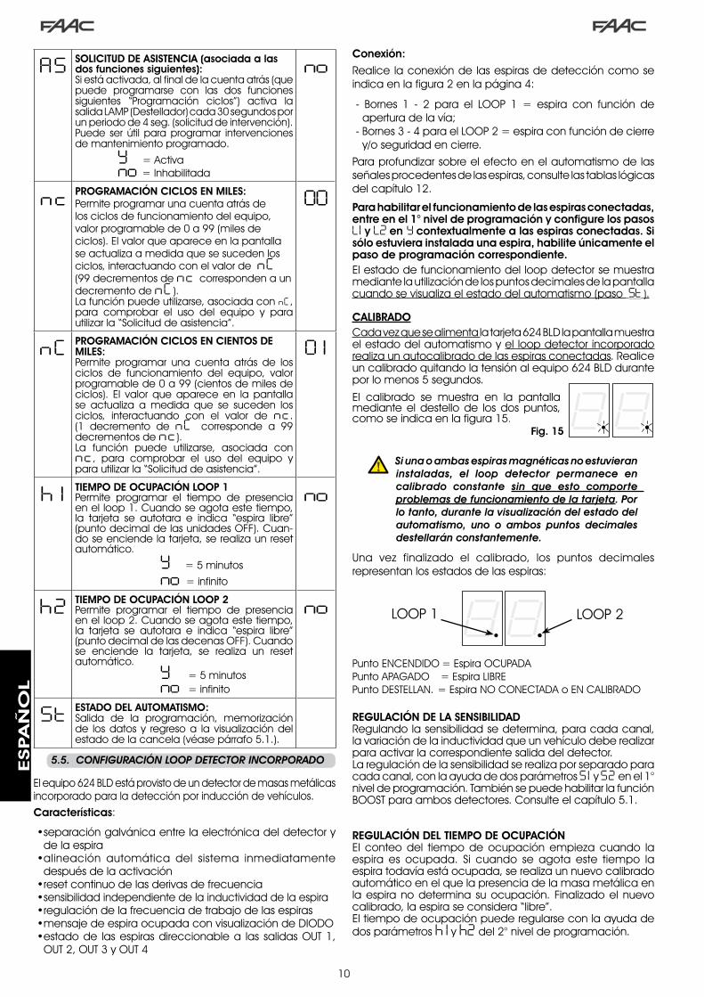
�0
AS SOLICITUD DE ASISTENCIA (asociada a las dos funciones siguientes):Si está activada, al final de la cuenta atrás (que puede programarse con las dos funciones siguientes “Programación ciclos”) activa la salida LAMP (Destellador) cada �0 segundos por un periodo de 4 seg. (solicitud de intervención). Puede ser útil para programar intervenciones de mantenimiento programado.
Y = Activa no = Inhabilitada
no
nc PROGRAMACIÓN CICLOS EN MILES:Permite programar una cuenta atrás de los ciclos de funcionamiento del equipo, valor programable de 0 a 99 (miles de ciclos). El valor que aparece en la pantalla se actualiza a medida que se suceden los ciclos, interactuando con el valor de nC (99 decrementos de nc corresponden a un decremento de nC ).La función puede utilizarse, asociada con nC , para comprobar el uso del equipo y para utilizar la “Solicitud de asistencia”.
00
nC PROGRAMACIÓN CICLOS EN CIENTOS DE MILES:Permite programar una cuenta atrás de los ciclos de funcionamiento del equipo, valor programable de 0 a 99 (cientos de miles de ciclos). El valor que aparece en la pantalla se actualiza a medida que se suceden los ciclos, interactuando con el valor de nc . (� decremento de nC corresponde a 99 decrementos de nc ).La función puede utilizarse, asociada con nc , para comprobar el uso del equipo y para utilizar la “Solicitud de asistencia”.
0 1
h 1 TIEMPO DE OCUPACIÓN LOOP 1Permite programar el tiempo de presencia en el loop �. Cuando se agota este tiempo, la tarjeta se autotara e indica “espira libre” (punto decimal de las unidades OFF). Cuan-do se enciende la tarjeta, se realiza un reset automático.
Y = 5 minutos no = infinito
no
h2 TIEMPO DE OCUPACIÓN LOOP 2Permite programar el tiempo de presencia en el loop �. Cuando se agota este tiempo, la tarjeta se autotara e indica “espira libre” (punto decimal de las decenas OFF). Cuando se enciende la tarjeta, se realiza un reset automático. Y = 5 minutos no = infinito
no
St ESTADO DEL AUTOMATISMO:Salida de la programación, memorización de los datos y regreso a la visualización del estado de la cancela (véase párrafo 5.�.).
5.5.. CONFIGURACIÓN.LOOP.DETECTOR.INCORPORADO
El equipo 6�4 BLD está provisto de un detector de masas metálicas incorporado para la detección por inducción de vehículos.Características:
separación galvánica entre la electrónica del detector y de la espiraalineación automática del sistema inmediatamente después de la activaciónreset continuo de las derivas de frecuenciasensibilidad independiente de la inductividad de la espiraregulación de la frecuencia de trabajo de las espirasmensaje de espira ocupada con visualización de DIODOestado de las espiras direccionable a las salidas OUT �, OUT �, OUT � y OUT 4
•
•
•••••
Punto ENCENDIDO = Espira OCUPADAPunto APAGADO = Espira LIBREPunto DESTELLAN. = Espira NO CONECTADA o EN CALIBRADO
LOOP � LOOP �
REGULACIÓN DE LA SENSIBILIDADRegulando la sensibilidad se determina, para cada canal, la variación de la inductividad que un vehículo debe realizar para activar la correspondiente salida del detector.La regulación de la sensibilidad se realiza por separado para cada canal, con la ayuda de dos parámetros S1 y S2 en el �° nivel de programación. También se puede habilitar la función BOOST para ambos detectores. Consulte el capítulo 5.�.
REGULACIÓN DEL TIEMPO DE OCUPACIÓNEl conteo del tiempo de ocupación empieza cuando la espira es ocupada. Si cuando se agota este tiempo la espira todavía está ocupada, se realiza un nuevo calibrado automático en el que la presencia de la masa metálica en la espira no determina su ocupación. Finalizado el nuevo calibrado, la espira se considera “libre”.El tiempo de ocupación puede regularse con la ayuda de dos parámetros h 1 y h2 del �° nivel de programación.
Conexión:
Realice la conexión de las espiras de detección como se indica en la figura � en la página 4:
- Bornes � - � para el LOOP � = espira con función de apertura de la vía;
- Bornes � - 4 para el LOOP � = espira con función de cierre y/o seguridad en cierre.
Para profundizar sobre el efecto en el automatismo de las señales procedentes de las espiras, consulte las tablas lógicas del capítulo ��.
Para habilitar el funcionamiento de las espiras conectadas, entre en el 1° nivel de programación y configure los pasos L1 y L2 en Y contextualmente a las espiras conectadas. Si sólo estuviera instalada una espira, habilite únicamente el paso de programación correspondiente.El estado de funcionamiento del loop detector se muestra mediante la utilización de los puntos decimales de la pantalla cuando se visualiza el estado del automatismo (paso St ).
CALIBRADOCada vez que se alimenta la tarjeta 6�4 BLD la pantalla muestra el estado del automatismo y el loop detector incorporado realiza un autocalibrado de las espiras conectadas. Realice un calibrado quitando la tensión al equipo 6�4 BLD durante por lo menos 5 segundos.
El calibrado se muestra en la pantalla mediante el destello de los dos puntos, como se indica en la figura �5.
. Si.una.o.ambas.espiras.magnéticas.no.estuvieran.instaladas,. el. loop. detector. permanece. en.calibrado. constante. sin. que. esto. comporte.problemas.de.funcionamiento.de.la.tarjeta..Por.lo.tanto,.durante.la.visualización.del.estado.del.automatismo,. uno. o. ambos. puntos. decimales.destellarán.constantemente.
Una vez finalizado el calibrado, los puntos decimales representan los estados de las espiras:
Fig. 15
ESPA
ÑO
L

��
.6.. PUESTA.EN.FUNCIONAMIENTO
6.1.. COMPROBACIONES.DE.LOS.DIODOS.TARJETA
Fig. 16
6.2.. COMPROBACIÓN.DEL.ESTADO.DEL.BUS
Consulte este párrafo si se han instalado fotocélulas BUS como se indica en el párrafo 4.3 en la página 5.Entre en el �° nivel de programación y visualice en la pantalla el paso de programación bu.
Dicho paso debe mostrar tres líneas horizontales para confirmar que todos los pares de fotocélulas BUS no están ocupadas.Consulte el párrafo 5.� en la página 8 para más detalles sobre la visualización de estos dispositivos.
.7.. PRUEBA.DEL.AUTOMATISMO
Cuando finalice la programación compruebe que el equipo funcione correctamente.Compruebe especialmente que la fuerza del automatismo esté bien ajustada y que los dispositivos de seguridad al mismo conectado intervengan correctamente.
Consulte el capítulo 5.4 REGULACIÓN DE LA FRECUENCIA y NUEVO EQUILIBRADO
La frecuencia de trabajo de cada uno de los canales del detector puede regularse en dos niveles mediante los DIP- switch DS� (véase fig.�).
DIP � ON = Frecuencia loop � BAJA OFF= Frecuencia loop � ALTA
DIP � ON = Frecuencia loop � BAJA OFF= Frecuencia loop � ALTASi se cambia uno de estos DIP se aconseja realizar un nuevo calibrado. En caso de instalación de dos espiras, seleccione frecuencias diferentes para cada espira.
NOTAS PARA LA REALIZACIÓN DE LAS ESPIRAS
La espira debe realizarse a por lo menos �5 cm. de distancia de objetos metálicos fijos, y a por lo menos 50 cm. de distancia de objetos metálicos en movimiento, y a no más de 5 cm. de la superficie del pavimento definitivo. Utilice un cable unipolar de �,5mm² de sección (si el cable se entierra, debe tener doble aislamiento). Realice una espira preferentemente cuadrada o rectangular, previendo antes un conducto para cables en PVC o bien realizando una regata en el pavimento, como se indica en la figura �6 (los ángulos deben cortarse a 45° para evitar que el cable pueda romperse). Coloque el cable realizando el número de arrollamientos indicado en la tabla. Los dos extremos del cable deben trenzarse entre sí (por lo menos �0 vueltas por cada metro) desde la espira hasta el al detector. Evite realizar empalmes en el cable (si fuera necesario, suelde los conductores y selle la unión con una vaina termorretráctil) y manténgalo separado de las líneas de alimentación de
red.Antes de la definitiva puesta en funcionamiento del equipo electrónico 6�4 BLD compruebe el estado de los DIODOS presentes en el mismo.Dichos DIODOS indican el estado de las entradas de la tarjeta y son de suma importancia para el movimiento del automatismo:
DIODO ENCENDIDO : contacto CERRADO
DIODO APAGADO : contacto ABIERTO
En la Figura 16 se indica la configuración de los DIODOS estándar con automatismo CERRADO listo para abrir.
Las entradas Emergencia (DL5), STOP (DL4), Fotocélulas (DL�) y Pivot (DL8) son entradas de seguridad con contacto N.C. (normalmente cerrado) por lo tanto los DIODOS correspondientes están ENCENDIDOS.
Los DIODOS FCA y FCC representan los contactos N.C de los finales de carrera que, si están ocupados, pasan a estar abiertos y, por consiguiente, apagan el DIODO correspondiente:
Con Automatismo CERRADOFCC OCUPADO
Con Automatismo ABIERTOFCA OCUPADO
Perímetro Espira
N° deArrollamientos
menos de � m 6
de � a 4 m 5
de 4 a 6 m 4
de 6 a �� m �
más de �� m �
mm
mm
Fig. 16
ESPA
ÑO
L

��
1 OFF2 OFF
Fig. 17
.8.. CONFIGURACIONES.MASTER-SLAVE
Si la instalación prevé el uso de dos barreras contrapuestas de accionamiento simultáneo en apertura/cierre de la vía, hay que utilizar uno de los diagramas de conexión abajo incluidos en función de las tarjetas electrónicas utilizadas para mover las barreras.
Por equipo MASTER (maestro) se entiende la tarjeta electrónica a la cual están conectados todos los emisores de impulso y los dispositivos de seguridad.Por equipo SLAVE (esclavo) se entiende la tarjeta electrónica que es controlada por la MASTER por medio de las entradas de impulso, mientras las entradas de seguridad están cortocircuitadas.
a ...PROGRAMACIÓN.DE.1°.NIVEL
LO = Cb ...PROGRAMACIÓN.DE.3°.NIVEL
03 = Yc PROGRAMACIÓN.DE.1°.NIVEL
LO = CU
ESPA
ÑO
L

��
La programación de �° nivel sólo se utiliza en caso de personalización avanzada de las lógicas de funcionamiento ya presentes en la memoria.
Antes. de. realizar. modificaciones. en. este. nivel,. asegúrese. de. que. ha. comprendido. plenamente. la.naturaleza.de.los.pasos.que.quiere.modificar.y.cómo.influyen.en.el.automatismo.
Para acceder a la PROGRAMACIÓN DE �° NIVEL hay que presionar el pulsador F y, manteniéndolo presionado, presionar el pulsador + durante unos 10 segundos. El uso de las teclas F, + y - es el mismo que el descrito para los otros dos niveles de programación.
PROGRAMACIÓN DE 3° NIVEL 10 seg.
D. Función Configuración
0 1 Activando esta función se obtiene el cierre automático transcurrido el tiempo de pausa. Y = cierre automáticono = desactiva
02 Activando esta función se obtiene el funcionamiento con dos entradas distintas: OPEN para la apertura y CLOSE para el cierre.
Y = funcionamiento con � entradasno = desactiva
03Activación del reconocimiento de los niveles de las entradas OPEN y CLOSE (mando mantenido). Esto es, la tarjeta reconoce el nivel (por ejemplo con OPEN mantenido y si se presiona STOP, al soltar éste último el automatismo sigue abriendo). Si 0� está desactivado, la tarjeta manda una maniobra sólo ante una variación de la entrada.
Y = reconocimiento del nivelno = reconocimiento al
cambiar el estado
04 Activación de apertura del tipo PRESENCIA OPERADOR (mando siempre presionado). Al soltar el mando de OPEN se bloquea el funcionamiento
Y = activano = desactiva
05Activando esta función, el mando de OPEN durante la apertura detiene el movimiento.Si el parámetro 06 es no el sistema está listo para la apertura.Si el parámetro 06 es Y el sistema está listo para el cierre.
Y = en apertura bloqueano = desactiva
06 Activando esta función, el mando de OPEN durante la apertura invierte el movimiento.Si los parámetros 05 y 06 son no el OPEN no tiene ningún efecto durante la apertura.
Y = en apertura invierteno = desactiva
07Activando esta función, el mando de OPEN durante la pausa bloquea el funcionamiento.Si los parámetros 07 y 08 son no el OPEN recarga el tiempo de pausa.
Y = en pausa bloqueano = desactiva
08 Activando esta función, el mando de OPEN durante la pausa ocasiona el cierre.Si los parámetros 07 y 08 son no , el OPEN recarga el tiempo de pausa.
Y = en pausa cierrano = desactiva
09 Activando esta función, el mando de OPEN durante el cierre bloquea el funcionamiento, de otro modo invierte el movimiento..
Y = bloqueano = invierte
10 Activación de cierre del tipo PRESENCIA OPERADOR (mando siempre presionado). Al soltar el mando de CLOSE se bloquea el funcionamiento.
Y = activano = desactiva
1 1 Activando esta función, el mando CLOSE tiene prioridad sobre el OPEN, de otro modo el OPEN tendrá prioridad sobre el CLOSEE.
Y = activano = desactiva
12 Activando esta función, el mando CLOSE manda el cierre al soltar el mismo. Mientras CLOSE está activo, la unidad permanece en predestello de cierre.
Y = cierra al soltarno = cierra inmediatamente
13Activando esta función, el mando CLOSE durante la apertura bloquea el funcionamiento, de otro modo el mando CLOSE manda la inversión inmediatamente o al final de la apertura (véase también el parámetro 14)
Y = CLOSE bloqueano = CLOSE invierte
14 Activando esta función, si el parámetro 13 es no, el mando CLOSE manda el cierre inmediato cuando termina el ciclo de apertura (memoriza el CLOSE). Si los parámetros 13 y 14 son no CLOSE, manda el cierre inmediato.
Y = cierra al final de la aperturano = cierre inmediato
15 Activando esta función con el sistema bloqueado por un STOP, un sucesivo OPEN mueve en la dirección opuesta. Si el parámetro 15 es no cierra siempre.
Y = mueve en dirección opuesta
no = cierra siempre
16Activando esta función, durante el cierre, los DISP. DE SEGURIDAD EN CIERRE bloquean y permiten que se reanude el movimiento al liberarse, de otro modo invierten inmediatamente en apertura.
Y = cierra al liberarseno = inversión inmediata
17Activando esta función, los DISP. DE SEGURIDAD EN CIERRE mandan el cierre al liberarse.(véase también el parámetro 18).
Y = cierre cuando se libera el FSW
no = desactiva
18 Activando esta función, y si el parámetro 17 es Y, la unidad espera a que termine el ciclo de apertura antes de ejecutar el mando de cierre dado por los DISPOSITIVOS DE SEGURIDAD EN CIERRE.
Y = cierra al final de la apertura
no = desactiva
19 Activando esta función, durante el cierre, LOOP2 bloquea y permite que se reanude el movimiento al liberarse, de otro modo invierte inmediatamente en apertura.
Y = cierre al liberarseno = inversión inmediata
20 Activando esta función, LOOP2 manda el cierre al liberarse (véase también el parámetro 21).
Y = cierra si LOOP� está libreno = desactiva
2 1 Activando esta función, y si el parámetro 20 es Y , la unidad espera a que termine el ciclo de apertura antes de ejecutar el mando de cierre dado por LOOP2.
Y = cierra al final de la apertura
no = desactiva
22 Activando esta función los mandos de LOOP� son prioritarios respecto a los de LOOP�. Y = activano = desactiva
.9.. PROGRAMACIÓN.DE.3°.NIVEL
ESPA
ÑO
L

�4
D. Función Configuración
23El LOOP 1 manda una apertura y, al final de la misma, cierra si está libre (útil en caso de retroceso del vehículo con loops consecutivos). Si está desactivado, cuando se libera el LOOP � no se realiza el cierre
Y = cierra si LOOP� está libreno = desactiva
24 NO UTILIZADO /
25Función A.D.M.A.P.Activando esta función se obtiene el funcionamiento de los dispositivos de seguridad de conformidad con las normativas francesas.
Y = activano = desactiva
26 Activando esta función, los DISP. DE SEGURIDAD EN CIERRE durante el cierre bloquean e invierten el movimiento al liberarse, de otro modo invierten inmediatamente.
Y = bloquea e invierte al liberarse.
no=invierte inmediatamente.
27 NINGÚN EFECTO /
A 1PREDESTELLO:Permite regular, a pasos de � segundo, la duración del predestello deseado, desde un mínimo de 0 a un máximo de 10 segundos
05
A2TIMEOUT DE INVERSIÓN EN CIERRE:Activando esta función, durante el cierre se puede decidir si invertir o bloquear el movimiento cuando finaliza el timeout (no se alcanza el final de carrera de cierre.
Y = inversiónno = bloqueo
A3APERTURA AL ENCENDER:En caso de que faltara la tensión de línea, habilitando esta función se puede, cuando se restablece la tensión, mandar una apertura (sólo si el automatismo no está cerrado, FCC libre).
Y = aperturano = permanece parado
A4TIEMPO ACTIVACIÓN PRESÓSTATO FAAC CITY (J5):Es el tiempo transcurrido el cual la unidad considera la señal procedente del presóstato como FINAL DE CARRERA DE CIERRE.Puede regularse de 0 a 59 seg. a pasos de un segundo. Seguidamente la visualización pasa a ser en minutos y en decenas de segundos (separados por un punto) hasta el valor máximo de 4,1 minutos.
4.0
A5DESACTIVACIÓN PRESÓSTATO PILONES AL INICIO DEL MOVIMIENTO: Para un correcto funcionamiento del pilón es necesario desactivar el control del presóstato al inicio de la maniobra de subida (tiempo 0,4 segundos).Programar esta función en Y con pilones.
Y = presóstato desactivado en el punto de arranqueno = presóstato siempre activo
A6CONTROL ALIMENTACIÓN ELECTROVÁLVULA PILONES (bornes 22-23):FAAC CITY K - J�75K: salida electroválvula normalmente desalimentada - alimentada durante la bajada.FAAC CITY - J�75 estándar: salida electroválvula normalmente alimentada - desalimentada durante la bajada.
Y = para FAAC CITY K /J�75K no = para FAAC CITY estándar y J�75
A7 POLARIDAD FINAL DE CARRERA DE APERTURA:Configuración del contacto de final de carrera
Y = polaridad NOno = polaridad NC
A8 POLARIDAD FINAL DE CARRERA DE CIERRE:Configuración del contacto de final de carrera
Y = polaridad NOno = polaridad NC
A9HABILITACIÓN PRESÓSTATO FAAC CITY (J5):Reconocimiento del contacto PRESÓSTATO como seguridad durante la primera fase de subida y de final de carrera transcurrido el tiempo de activación presóstato FAAC CITY (parámetro A4):
Y = Funcionamiento para FAAC CITY
no = Funcionamiento final de carrera estándar
b0PRESÓSTATO DE SÓLO SEGURIDAD PARA PILONES (bornes 7 - GND):
Reconocimiento del contacto FOTOCÉLULA como PRESÓSTATO de seguridad.(el contacto es ignorado al inicio del movimiento y al final de la subida)
Y = Funcionamiento del presóstato de sólo seguridadno = Funcionamiento
fotocélulas estándar
b 1 RETARDO INTERVENCIÓN FUNCIÓN HOLD CLOSE / HOLD OPEN:Tiempo de retardo en la activación de la función HOLD CLOSE / HOLD OPEN (véanse parámetros b� y b4). El conteo empieza cuando se alcanza el final de carrera interesado.Si una vez transcurrido el tiempo programado el final de carrera está libre involuntariamente se activa la función HOLD CLOSE / HOLD OPEN. 00 = activación inmediata de HOLD CLOSE / HOLD OPEN 01 a 99 = minutos de conteo antes de la activación HOLD CLOSE / HOLD OPEN
30
b2 NO MODIFICAR 30b3 FUNCIÓN HOLD CLOSE:
Si el final de carrera de cierre se abandona involuntariamente, la tarjeta manda en automático un movimiento durante un tiempo de � segundos para intentar restablecer la posición; si en este tiempo el final de carrera de cierre no es ocupado, el automatismo se activará al máximo por el tiempo de trabajo “t” véase el �° NIV. PROGRAMACIÓN:
Y = activano = desactiva
b4 FUNCIÓN HOLD OPEN:Si el final de carrera de apertura se abandona involuntariamente, la tarjeta manda en automático un movimiento durante un tiempo de � segundos para intentar restablecer la posición; si en este tiempo el final de carrera de apertura no es ocupado, el automatismo se activará al máximo por el tiempo de trabajo “t” véase el �° NIV. PROGRAMACIÓN (se aconseja programar el parámetro A3 en Y si el parámetro b3 está programado en Y)
Y = activano = desactiva
ESPA
ÑO
L

�5
9.1.. PERSONALIZACIÓN.DE.LA.LÓGICA.DE. . FUNCIONAMIENTO
Los valores de programación del �° nivel cambian en función de la lógica seleccionada en el primer nivel de programación.
El �° nivel de programación está dedicado a la personalización de una de las lógicas seleccionables, en caso de que se necesite un comportamiento no estándar de la aplicación.
Para que sea efectiva la modificación de uno o varios parámetros del �° nivel de programación que personalizan el funcionamiento de la lógica configurada, proceda del siguiente modo:
Seleccione una de las lógicas de base que se adapte mejor a sus exigencias.Entre en el �° nivel de programación y modifique los parámetros deseados.Salga del �° nivel y desde el �° nivel seleccione la lógica Cu.
La lógica Cu hace que sean activas las modificaciones aportadas al �° nivel.
En la siguiente tabla se indican los parámetros por defecto que afectan a las lógicas de funcionamiento.
�.
�.
�.
Paso A A1 E P PA Cn CA rb C
0 1 Y Y N N Y N Y Y N02 N N N Y Y Y Y Y Y03 N N N N N N N Y N04 N N N N N N N N Y05 N N Y N N N N N N06 N N Y N N N N N N07 N N N N N N N N N08 N N N N N N N N N09 N N N N N N N N N10 N N N N N N N N Y1 1 N N N N N N N N N12 N N N Y Y N N N N13 N N N N N N N N N14 N N N Y Y Y Y N N15 N N N N N N N N N16 N N N Y Y N N N N17 N Y N N N N N N N18 N Y N N N N N N N19 N N N Y Y N N N N20 N Y N Y Y Y Y N N2 1 N Y N Y Y Y Y N N22 N N N N N Y Y N N23 N N N Y Y N N N N24 N N N N N N N N N25 N N N N N N N N N26 N N N N N N N N N
.10.. VALORES.DE.LAS.PRE-CONFIGURACIONES
En la tabla inferior se indican los valores de los pasos de cada nivel de programación en relación a la pre-configuración seleccionada
1° NIVEL
2° NIVEL
Por defecto FAAC1
RESERVADO FAAC
Por defecto FAAC CITY
Por defecto FAAC CITY K
Por defecto J275
Por defecto J275K
dF pre-configuración 0 1 02 03 04 05 06bu BUS
Lo lógica E A1 rb rb rb rbPA pausa 20 20 30 30 30 30FO fuerza 50 50 50 50 50 50L 1 loop � no no no no no noL2 loop � no no no no no noH 1 loop � no no no no no noH 2 loop � no no no no no noS 1 sensibilidad 05 05 05 05 05 05S2 sensibilidad 05 05 05 05 05 05
bo boost Y Y Y Y Y YPF predestello no CL no no no noSC cierre lento no no no no no notr deceleración 03 03 0 1 0 1 0 1 0 1t time out 20 20 12 12 12 12FS fail safe no no no no no noo 1 salida � 00 16 15 15 15 15P 1 polaridad � no no no no no noo2 salida � 03 17 14 14 03 03P2 polaridad � no no no no no noo3 salida � 0 1 0 1 0 1 0 1 0 2 0 2P3 polaridad � no no no no no noo4 salida 4 00 00 00 00 00 00P4 polaridad 4 no no no no no noA5 asistencia no no no no no nonc ciclos �. 00 00 00 00 00 00nC ciclos �. 0 1 0 1 0 1 0 1 0 1 0 1h 1 ocupación no no no no no noh2 ocupación no no no no no no
b5 GESTIÓN ELECTROVÁLVULA PILONES:Esta función debe programarse en Y para J�75 /J�75KEsta función debe programarse en no para FAAC CITY / FAAC CITY K.
Y = para J�75 / J�75Kno= FAAC CITY / FAAC CITY K
b6 LÓGICA DE FUNCIONAMIENTO ENTRADA EMERGENCIA:Al activar esta función la entrada de emergencia manda un cierre, que se mantiene hasta que se restablece el contacto.Si la función está desactivada, la entrada de emergencia manda una apertura, que se mantiene hasta que se restablece el contacto.
Y = activano = desactiva
St ESTADO DEL AUTOMATISMO:Salida de la programación, memorización de los datos y visualización del estado de la cancela (véase párrafo 5.�.).
D. Función Configuración
Por defecto FAAC1
RESERVADO FAAC
Por defecto FAAC CITY
Por defecto FAAC CITY K
Por defecto J275
Por defecto J275K
ESPA
ÑO
L

�6
____________________________________________________
_____________________________________________________
________________________________________________________________________________________________________
1918
1617
1514
1213
1011
89
67
45
23
1
OPEN A
STOP
LOOP 1
LOOP 2
LOOP 2
LOOP 1
CLOSE
FSW
EMERGENCY
OUT 1
OUT 2
OUT 4
OUT 3
GND
GND
GND
+24 V
+24 V
OUT 3
J119
1816
1715
1412
1310
118
96
74
52
31
OPEN A
STOP
LOOP 1
LOOP 2
LOOP 2
LOOP 1
CLOSE
FSW
EMERGENCY
OUT 1
OUT 2
OUT 4
OUT 3
GND
GND
GND
+24 V
+24 V
OUT 3
J119
1816
1715
1412
1310
118
96
74
52
31
OPEN A
STOP
LOOP 1
LOOP 2
LOOP 2
LOOP 1
CLOSE
FSW
EMERGENCY
OUT 1
OUT 2
OUT 4
OUT 3
GND
GND
GND
+24 V
+24 V
OUT 3
J1
.11.. NOTAS
La función de interbloqueo permite gestionar dos barreras en línea (véase fig.) de manera tal que la apertura de una esté subordinada al cierre de la otra.El funcionamiento puede ser monodireccional o bidireccional.
.12.. CONEXIÓN.INTERBLOQUEO
Fig. 18
08 no no no no no no09 no no no no no no10 no no no no no no1 1 no no no no no no12 no no no no no no13 no no no no no no14 no no no no no no15 no no no no no no16 no no no no no no17 no Y no no no no18 no Y no no no no19 no no no no no no20 no Y no no no no2 1 no Y no no no no22 no no no no no no23 no no no no no no24 no no no no no no25 no no no no no no26 no no no no no no27 no no no no no noA 1 05 0 1 05 05 05 05A2 no no no no no noA3 no no no no no noA4 4 .0 4 .0 04 04 4 .0 4 .0A5 no no Y Y Y YA6 no no no Y no YA7 no no Y Y no noA8 no no no Y no noA9 no no Y Y no nob0 no no no no Y Yb 1 00 00 30 30 30 30b2 30 30 30 30 30 30b3 no no Y Y Y Yb4 no no no no no nob5 no no no no Y Yb6 no no no no no no
0 1 no Y Y Y Y Y02 no no Y Y Y Y03 no no Y Y Y Y04 no no no no no no05 Y no no no no no06 Y no no no no no07 no no no no no no
Por defecto FAAC1
RESERVADO FAAC
Por defecto FAAC CITY
Por defecto FAAC CITY K
Por defecto J275
Por defecto J275K
3° NIVEL
Para barreras en línea habilite OUT� INTERBLOQUEO en el parámetro �8 (véase PROG. �° NIVEL) en ambas tarjetas y conéctelas como se indica en la fig.�8
ESPA
ÑO
L

�7
Tab. 1/b
Tab. 1/a
LÓGICA “A” IMPULSOS
ESTADO DEL AUTOMATISMO OPEN A CLOSE STOP FSW LOOP 1 LOOP 2
CERRADOabre y vuelve a
cerrar transcurrido el tiempo de
pausaningún efecto
ningún efecto (apertura inhibida)
ningún efectoabre y vuelve a
cerrar transcurrido el tiempo de
pausaningún efecto
EN APERTURA ningún efecto invierte en cierre inmediatamente
bloquea el funcionamiento ningún efecto ningún efecto ningún efecto
ABIERTO EN PAUSA recarga el tiempo de pausa cierra bloquea el
funcionamiento
recarga el tiempo de pausa
(cierre inhibido)
recarga el tiempo de pausa
recarga el tiempo de pausa
(cierre inhibido)
EN CIERREinvierte en apertura
inmediatamenteningún efecto bloquea el
funcionamiento
invierte en apertura
inmediatamente
invierte en apertura
inmediatamente
invierte en apertura
inmediatamente
BLOQUEADO cierra cierraningún efecto
(apertura y cierre inhibidos)
ningún efecto (cierre inhibido)
abre y vuelve a cerrar transcurrido
el tiempo de pausa
ningún efecto (cierre inhibido)
LÓGICA “A1” IMPULSOS
ESTADO DEL AUTOMATISMO OPEN A CLOSE STOP FSW LOOP 1 LOOP 2
CERRADOabre y vuelve a
cerrar transcurrido el tiempo de
pausaningún efecto
ningún efecto (apertura inhibida)
ningún efectoabre y vuelve a
cerrar transcurrido el tiempo de
pausaningún efecto
EN APERTURA ningún efecto invierte en cierre inmediatamente
bloquea el funcionamiento
cierra inmediatamente
al final de la apertura
ningún efectocierra
inmediatamente al final de la
apertura
ABIERTO EN PAUSA recarga el tiempo de pausa cierra bloquea el
funcionamiento cierra recarga el tiempo de pausa cierra
EN CIERREinvierte en apertura
inmediatamenteningún efecto bloquea el
funcionamiento
invierte en apertura
inmediatamente
invierte en apertura inmediatamente,
cierra transcurrido el tiempo de
pausa
invierte en apertura
inmediatamente, vuelve a cerrar
cuando finaliza la apertura
BLOQUEADO cierra cierraningún efecto
(apertura y cierre inhibidos)
ningún efecto (cierre inhibido)
abre y vuelve a cerrar transcurrido el
tiempo de pausaningún efecto (cierre inhibido)
LÓGICA “E” IMPULSOS
ESTADO DEL AUTOMATISMO OPEN A CLOSE STOP FSW LOOP 1 LOOP 2
CERRADO abre ningún efectoningún efecto
(apertura inhibida)
ningún efecto abre ningún efecto
EN APERTURA bloquea el funcionamiento
invierte en cierre inmediatamente
bloquea el funcionamiento ningún efecto ningún efecto ningún efecto
ABIERTO cierra cierra ningún efecto (cierre inhibido)
ningún efecto (cierre inhibido) cierra ningún efecto
(cierre inhibido)
EN CIERREinvierte en apertura
inmediatamenteningún efecto bloquea el
funcionamiento
invierte en apertura
inmediatamente
invierte en apertura
inmediatamente
invierte en apertura
inmediatamente
BLOQUEADO cierra cierraningún efecto
(apertura y cierre inhibidos)
ningún efecto (cierre inhibido) abre ningún efecto
(cierre inhibido)
Entre paréntesis los efectos sobre las restantes entradas de impulso activo
.13.. TABLAS.LÓGICAS.DE.FUNCIONAMIENTO
Tab. 1/c
ESPA
ÑO
L

�8
Tab. 1/d
Tab. 1/e
Tab. 1/f
LÓGICA “P” IMPULSOS
ESTADO DEL AUTOMATISMO OPEN A CLOSE STOP FSW LOOP 1 LOOP 2
CERRADO abre ningún efecto ningún efecto (apertura inhibida) ningún efecto
abre, y finalizada la apertura, cierra
si está libreningún efecto
EN APERTURA ningún efecto cierra
inmediatamente al final de la
apertura
bloquea el funcionamiento ningún efecto ningún efecto
cierra inmediatamente
al final de la apertura
ABIERTO ningún efecto(cierre inhibido) cierra ningún efecto
(cierre inhibido)ningún efecto (cierre inhibido) Impide el cierre cierra
EN CIERREinvierte en apertura
inmediatamenteningún efecto bloquea el
funcionamiento
bloquea, y cuando se
libera, continúa cerrando
invierte en apertura inmediatamente y, cuando finaliza la apertura, cierra si
está libre
bloquea, y cuando se
libera, continúa cerrando
BLOQUEADO abre cierraningún efecto
(apertura y cierre inhibidos)
ningún efecto (cierre inhibido)
abre, y finalizada la apertura, cierra
si está libreningún efecto (cierre inhibido)
Entre paréntesis los efectos sobre las restantes entradas de impulso activo
LÓGICA “PA” IMPULSOS
ESTADO DEL AUTOMATISMO OPEN A CLOSE STOP FSW LOOP 1 LOOP 2
CERRADOabre y vuelve a
cerrar transcurrido el tiempo de
pausaningún efecto ningún efecto
(apertura inhibida) ningún efecto abre, y finalizada la apertura, cierra
si está libreningún efecto
EN APERTURA ningún efecto cierra
inmediatamente al final de la
apertura
bloquea el funcionamiento ningún efecto ningún efecto
cierra inmediatamente
al final de la apertura
ABIERTO EN PAUSA recarga el tiempo de pausa cierra bloquea el
funcionamiento
recarga el tiempo de
pausa(cierre inhibido)
recarga el tiempo de pausa cierra
EN CIERREinvierte en apertura
inmediatamenteningún efecto bloquea el
funcionamiento
bloquea, y cuando se
libera, continúa cerrando
invierte en apertura inmediatamente y, cuando finaliza la apertura, cierra si
está libre
bloquea, y cuando se
libera, continúa cerrando
BLOQUEADOabre y vuelve a
cerrar transcurrido el tiempo de
pausacierra
ningún efecto (apertura y cierre
inhibidos)ningún efecto (cierre inhibido)
abre, y finalizada la apertura, cierra
si está libreningún efecto (cierre inhibido)
LÓGICA “Cn” IMPULSOS
ESTADO DEL AUTOMATISMO OPEN A CLOSE STOP FSW LOOP 1 LOOP 2
CERRADO abre ningún efecto ningún efecto (apertura inhibida) ningún efecto abre ningún efecto
EN APERTURA ningún efecto cierra
inmediatamente al final de la
apertura
bloquea el funcionamiento ningún efecto ningún efecto
cierra inmediatamente
al final de la apertura
ABIERTO ningún efecto (cierre inhibido) cierra ningún efecto
(cierre inhibido)ningún efecto (cierre inhibido) ningún efecto cierra
EN CIERREinvierte en apertura
inmediatamenteningún efecto bloquea el
funcionamiento
invierte en apertura y cierra transcurrido el tiempo de pausa
invierte en apertura
inmediatamente
invierte en apertura
inmediatamente
BLOQUEADO abre cierraningún efecto
(apertura y cierre inhibidos)
ningún efecto (cierre inhibido) abre ningún efecto
(cierre inhibido)
ESPA
ÑO
L
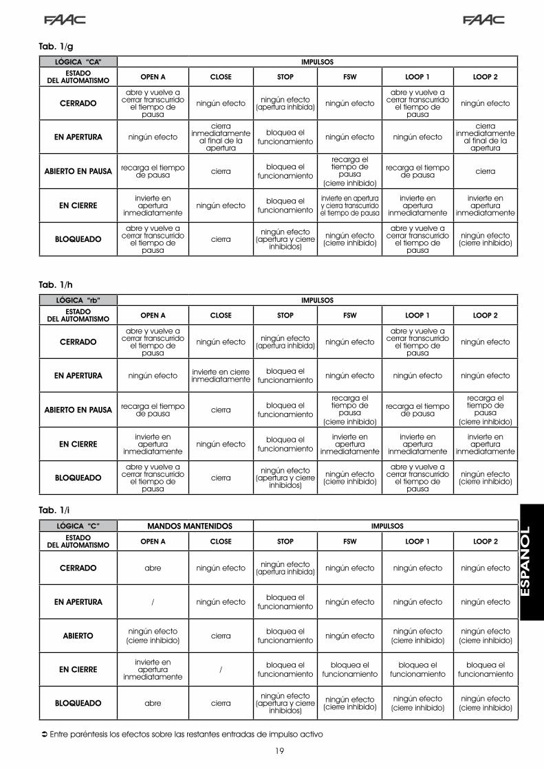
�9
Tab. 1/i
Tab. 1/g
Tab. 1/h
LÓGICA “CA” IMPULSOS
ESTADO DEL AUTOMATISMO OPEN A CLOSE STOP FSW LOOP 1 LOOP 2
CERRADOabre y vuelve a
cerrar transcurrido el tiempo de
pausaningún efecto ningún efecto
(apertura inhibida) ningún efecto abre y vuelve a
cerrar transcurrido el tiempo de
pausaningún efecto
EN APERTURA ningún efecto cierra
inmediatamente al final de la
apertura
bloquea el funcionamiento ningún efecto ningún efecto
cierra inmediatamente
al final de la apertura
ABIERTO EN PAUSA recarga el tiempo de pausa cierra bloquea el
funcionamiento
recarga el tiempo de
pausa(cierre inhibido)
recarga el tiempo de pausa cierra
EN CIERREinvierte en apertura
inmediatamenteningún efecto bloquea el
funcionamiento
invierte en apertura y cierra transcurrido el tiempo de pausa
invierte en apertura
inmediatamente
invierte en apertura
inmediatamente
BLOQUEADOabre y vuelve a
cerrar transcurrido el tiempo de
pausacierra
ningún efecto (apertura y cierre
inhibidos)ningún efecto (cierre inhibido)
abre y vuelve a cerrar transcurrido
el tiempo de pausa
ningún efecto (cierre inhibido)
LÓGICA “rb” IMPULSOS
ESTADO DEL AUTOMATISMO OPEN A CLOSE STOP FSW LOOP 1 LOOP 2
CERRADOabre y vuelve a
cerrar transcurrido el tiempo de
pausaningún efecto ningún efecto
(apertura inhibida) ningún efecto abre y vuelve a
cerrar transcurrido el tiempo de
pausaningún efecto
EN APERTURA ningún efecto invierte en cierre inmediatamente
bloquea el funcionamiento ningún efecto ningún efecto ningún efecto
ABIERTO EN PAUSA recarga el tiempo de pausa cierra bloquea el
funcionamiento
recarga el tiempo de
pausa(cierre inhibido)
recarga el tiempo de pausa
recarga el tiempo de
pausa(cierre inhibido)
EN CIERREinvierte en apertura
inmediatamenteningún efecto bloquea el
funcionamiento
invierte en apertura
inmediatamente
invierte en apertura
inmediatamente
invierte en apertura
inmediatamente
BLOQUEADOabre y vuelve a
cerrar transcurrido el tiempo de
pausacierra
ningún efecto (apertura y cierre
inhibidos)ningún efecto (cierre inhibido)
abre y vuelve a cerrar transcurrido
el tiempo de pausa
ningún efecto (cierre inhibido)
Entre paréntesis los efectos sobre las restantes entradas de impulso activo
LÓGICA “C” MANDOS MANTENIDOS IMPULSOS
ESTADO DEL AUTOMATISMO OPEN A CLOSE STOP FSW LOOP 1 LOOP 2
CERRADO abre ningún efecto ningún efecto (apertura inhibida) ningún efecto ningún efecto ningún efecto
EN APERTURA / ningún efecto bloquea el funcionamiento ningún efecto ningún efecto ningún efecto
ABIERTO ningún efecto (cierre inhibido) cierra bloquea el
funcionamiento ningún efecto ningún efecto (cierre inhibido)
ningún efecto (cierre inhibido)
EN CIERREinvierte en apertura
inmediatamente/ bloquea el
funcionamientobloquea el
funcionamientobloquea el
funcionamientobloquea el
funcionamiento
BLOQUEADO abre cierraningún efecto
(apertura y cierre inhibidos)
ningún efecto (cierre inhibido)
ningún efecto (cierre inhibido)
ningún efecto (cierre inhibido)
ESPA
ÑO
L

�
INHOUDSOPGAVE1....WAARSCHUWINGEN.....................................................................................................................................3
2....TECHNISCHE.EIGENSCHAPPEN......................................................................................................................3
3....LAY-OUT.EN.ONDERDELEN.624BLD...............................................................................................................3
3.1.Beschrijving.en.onderdelen...................................................................................................................3
4....ELEKTRICITEITSAANSLUITINGEN.....................................................................................................................4
4.1...Klemmenbord.J1.-.Accessoires.(Fig..2)...............................................................................................4
4.2...Aansluiting.fotocellen.op.relais.en.veiligheidsvoorzieningen.met.contact.“N.C.”.............................5
4.3...Aansluiting.BUS-fotocellen...................................................................................................................5
4.4...Klemmenbord.J2.-.Motor,.waarschuwingslamp.en.ventilator.(Fig..2)................................................6
4.5...Connector.J8.-.Condensator.motor.(Fig..2)........................................................................................6
4.6...Klemmenbord.J9.-.Accessoires.(Fig..2)...............................................................................................6
4.7...Connectoren.J3,.J5.–Snelaansluiting.eindschakelaar.openen.en.sluiten.(Fig..2)..............................6
4.8...Connector.J6.–.Sensor.forcering.boom.(Fig..2)....................................................................................6
4.9...Frequentieschakelaar.DS1.(Fig..1).......................................................................................................6
4.10.Connector.J4.-.Snelaansluiting.Minidec,.Decoder.en.RP.......................................................................6
5....PROGRAMMERING.......................................................................................................................................6
5.1...PROGRAMMERING.1e.NIVEAU..............................................................................................................6
5.2...Wijziging.van.de.pre-setting...............................................................................................................8
5.3...Instelling.en.controle.BUS-systeem......................................................................................................8
5.4...PROGRAMMERING.2e.NIVEAU..............................................................................................................9
5.5...Instelling.ingebouwde.Loop.Detector.................................................................................................10
6....INBEDRIJFSTELLING.......................................................................................................................................11
6.1...Controle.van.de.LEDs.op.de.kaart......................................................................................................11
6.2...Controle.status.van.de.BUS.................................................................................................................11
7....TEST.VAN.HET.AUTOMATISCHE.SYSTEEM...........................................................................................................11
8....CONFIGURATIES.MASTER-SLAVE....................................................................................................................12
9....PROGRAMMERING.3e.NIVEAU......................................................................................................................13
9.1...Aanpassen.bedrijfslogica.aan.wensen.klant......................................................................................15
10..WAARDEN.PRE-SETTING................................................................................................................................15
11..OPMERKINGEN.............................................................................................................................................16
12..AANSLUITING.TUSSENBLOKKERING................................................................................................................16
13..TABELLEN.MET.BEDRIJFSLOGICA’S.................................................................................................................17
NED
ERLA
ND
S

�
CE-VERKLARING VAN OVEREENSTEMMING
Fabrikant: FAACS.p.A.
Adres: ViaCalari,�0-40069ZolaPredosaBOLOGNA-ITALIE
Verklaart dat: Deelektronischeapparatuur6�4BLD
•invereenstemmingismetdefundamenteleveiligheidseisenvandevolgendeEEG-richtijnen:
�006/95/EGLaagspanningsrichtijn �004/�08/EGrichtlijnElektromagnetischeCompatibiliteit
Aanvullendeopmerking: Ditproductisgetestineengebruikelijke,homogeneconfiguratie (alleproductengebouwddoorFAACS.p.A.).
Bologna,0�januari�0�0 DeAlgemeenDirecteur A.Marcellan
WAARSCHUWINGEN VOOR DE INSTALLATEURALGEMENE VEILIGHEIDSVOORSCHRIFTEN
1) LETOP!Hetisbelangrijkvoordeveiligheiddatdezeheleinstructiezorgvuldigwordtopgevolgd.Eenonjuisteinstallatieoffoutiefgebruikvanhetproductkanernstigpersoonlijkletselveroorzaken.
2) Leesdeinstructiesaandachtigdooralvorenstebeginnenmetdeinstallatievanhetproduct.
3) Deverpakkingsmaterialen(plastic,polystyreen,enz.)mogennietbinnenhetbereikvankinderenwordenbewaard,aangezienzijeenmogelijkebronvangevaarvormen.
4) Bewaardeinstructiesvoorraadplegingindetoekomst.
5) Ditproductisuitsluitendontworpenenvervaardigdvoorhetgebruikdatindezedocumentatiewordtbeschreven.Elkandergebruik,datnietuitdrukkelijkisvermeld,zouhetproductkunnenbeschadigenen/ofeenbronvangevaarkunnenvormen.
6) FAACaanvaardtgeenenkeleaansprakelijkheidvoorschadedieisontstaanuitoneigenlijkgebruikofuitelkandergebruikdanhetgeenwaarvoorhetautomatischesysteemisbedoeld.
7) Installeerhetapparaatnietineenexplosiegevaarlijkeomgeving:deaanwe-zigheidvanontvlambaregassenofdampenvormteenernstiggevaarvoordeveiligheid.
8) Demechanischeconstructie-elementenmoeten inovereenstemmingzijnmetdebepalingenvandenormenEN12604enEN12605.
In niet-EEG landen moeten, om een goed veiligheidsniveau te bereiken,behalvedenationalevoorschriftenookdebovenstaandenormeninachtwordengenomen.
9) FAACisnietaansprakelijkvoorhetnietinachtnemenvandegewoonte-regelsvoordetechnischeconstructievanhetsluitwerkdatgemotoriseerdmoetworden,nochvoorvervormingendiezoudenkunnenontstaanbijhetgebruik.
10) DeinstallatiemoetwordenuitgevoerdinovereenstemmingmetdenormenEN12453enEN12445.
In niet-EEG landen moeten, om een goed veiligheidsniveau te bereiken,behalvedenationalevoorschriftenookdebovenstaandenormeninachtwordengenomen.
11) Alvorenswerkzaamhedenaanhetsysteemuittevoeren,moetdevoedingwordenafgesloten.
12) Zorgophetvoedingsnetvanhetautomatischesysteemvooreenmeerpoligeschakelaarmeteenopeningtussendecontactenvan3mmofmeer.Hetisraadzaameenthermomagnetischeschakelaarvan6Ategebruikenmetmeerpoligeonderbreking.
13) Controleeroferbovenstroomsvanhetsysteemeendifferentiaalschakelaarisgeplaatstmeteendrempelspanningvan0,03A.
14) Controleerofdeaardingvakkundigisuitgevoerdensluitdemetalendelenvanhetsluitingeropaan.
15) Hetautomatischesysteembeschiktovereenintrinsiekebeveiligingtegeninklemming,bestaandeuiteenkoppelcontrole.Deinschakellimiethiervandient echter te worden gecontroleerd volgens de bepalingen van denormendiewordenvermeldonderpunt10.
16) Deveiligheidsvoorzieningen(normEN12978)zorgenvoordebeschermingvan eventuele gevaarlijke gebieden tegen Mechanische gevaren doorbeweging,zoalsbijvoorbeeldinklemming,meesleuringofamputatie.
17) Hetisraadzaamomvoorelksysteemtenminsteeenlichtsignaaltegebrui-ken(bijv.FAACLIGHT)alsmedeeenwaarschuwingsborddatgoedopdeconstructievanhetsluitwerkmoetzijnbevestigd,endevoorzieningendiewordengenoemdbijpunt“16”.
18) FAACaanvaardtgeenenkeleaansprakelijkheidvoorwatbetreftdevei-ligheidendegoedewerkingvanhetautomatischesysteem,indienerinhetsysteemgebruikisgemaaktvancomponentendienietdoorFAACzijngeproduceerd.
19) GebruikvoorhetonderhouduitsluitendorigineleFAAC-onderdelen.
20) Brenggeenwijzigingenaanopcomponentendiedeeluitmakenvanhetautomatischesysteem.
21) De installateur dient alle informatie te verstrekken over de handmatigebediening van het systeem in noodgevallen en moet de gebruiker vanhetsysteemhetwaarschuwingsboekjeoverhandigendatwordtmeegele-verd.
22) Kinderenofvolwassenenmogenzichnietophoudenindebuurtvanhetproductterwijlditinwerkingis.
23) Houdradiobesturingenofandereimpulsgeversbuitenhetbereikvankin-deren,omtevoorkomendathetautomatischesysteemonbedoeldwordtingeschakeld.
24) Menmagalleenpasserenwanneerhetautomatischesysteemhelemaalstilstaat.
25) Degebruikermaggeenpogingentotreparatiedoenofdirectehandelingenuitvoeren,maardientzichhiervooruitsluitendtewendentotgekwalificeerdpersoneel.
26) Onderhoud:dewerkingvanhetsysteemdientminstenstweemaalperjaartewordengecontroleerd.Hierbijdientbijzondereaandachttewordenbesteedaandeveiligheidsvoorzieningen(inclusief,waarvoorzien,deduwkrachtvandeaandrijving)endeontgrendelmechanismen.
27) Alles wat niet uitdrukkelijk in deze instructies wordt aangegeven, is niettoegestaan
NED
ERLA
ND
S

�
.1.. WAARSCHUWINGEN Let op: Alvorens een willekeurige ingreep op de elektronische apparatuur uit te voeren (aansluitingen, onderhoud) moet altijd
de stroomvoorziening worden losgekoppeld.- Zorg dat er bovenstrooms van de installatie een magnetothermische differentieelschakelaar is gemonteerd met een geschikte
inschakellimiet.- Sluit de aardingskabel aan op de specifieke klem op connector J9 van de apparatuur (zie fig. 2).- Houd de voedingskabels altijd gescheiden van de bedienings- en beveiligingskabels (drukknop, ontvanger, fotocellen, etc.).
Om elektrische storingen te vermijden moeten gescheiden kabelmantels of afgeschermde kabels (met scherm aangesloten op de massa) worden gebruikt.
ELEKTRONISCHE APPARATUUR 624 BLD
.3.. LAY-OUT.EN.ONDERDELEN.624BLD
Voedingsspanning *��0V~(+6%-�0%)-50/60Hz
of��5V~(+6%-�0%)-50/60Hz
Opgenomen vermogen 7W
Max. belasting motor �000W
Voedingaccessoires �4Vdc
Max. stroom accessoires 500mA
Omgevingstemperatuur van-�0°Ctot+55°C
Beveiligingszekeringen *F�=F�0A-�50VF�=T0,8A-�50V
ofF�=F�0A-��0VF�=T0,8A-��0V
Werktijd Programmeerbaar(van0tot4min)
Pauzetijd Programmeerbaar(van0tot4min)
Kracht motor Programmeerbaarop50niveaus
Programmering �programmeringsniveausvooreengroteregebruiksflexibiliteit
Snelconnector5-pinskoppelingkaartMinidec,
Decoder,OntvangerRP/RP�
Programmeerbare uitgangen
4programmeerbareuitgangenmet�8verschillendefuncties
Eigenschappen
Beheervertragingen,multifunctioneledisplay,BUS-technologieen
INGEBOUWDEDETECTORVANMETALENMASSA’S
*Devoedingsspanningendezekeringenhangenafvandeaangeschafteversie
.2.. TECHNISCHE.EIGENSCHAPPEN
3.1.BESCHRIJVING.EN.ONDERDELEN
DL DISPLAYVOORSIGNALERINGENENPROGRAMMERING
LED CONTROLELEDSSTATUSINGANGEN
J1 KLEMMENBORDLAAGSPANNING
J2 KLEMMENBORDAANSLUITINGMOTOR,WAARSCHUWINGSLAMPENVENTILATOR
J3 CONNECTOREINDSCHAKELAAROPENEN
J4 CONNECTORDECODER/MINIDEC/ONTVANGERRP
J5 CONNECTOREINDSCHAKELAARSLUITEN
J6 CONNECTORSENSORFORCERINGBOOM
J8 CONNECTORAANLOOPCONDENSATORMOTOR
J9 KLEMMENBORDVOEDING��0VAC
DS1 SCHAKELAARFREQUENTIESLOOP�enLOOP�
F1 ZEKERINGMOTORENENPRIMAIREWIKK.TRANSFORMATOR(F5A)
F2 ZEKERINGLAAGSPANNINGENACCESSOIRES(T800mA)
F PROGRAMMEERKNOP“F”
+ PROGRAMMEERKNOP“+”
- PROGRAMMEERKNOP“-”
TF1 TRANSFORMATOR
Fig. 1
NED
ERLA
ND
S

4
.4.. ELEKTRICITEITSAANSLUITINGEN
Voor de aansluiting van de fotocellen
en de veiligheidsvoorzieningen, zie paragraaf 4.2.
BLA
UW
AANLOOPCONDENSATOR MOTOR
VENTILATOR
MOTOR
FORCERING BOOM
Fig. 2
LOOP 1 - Magnetische lus LOOP 1 (OPEN - klemmen 1-2): dient voor OPENENLOOP 2 - Magnetische lus LOOP 2 (SAFETY/CLOSE - klemmen 3-4): dient voor BEVEILIGING/SLUITENOPEN - Commando “Openen” (N.O. - klem 5): hiermeewordtiedereimpulsgeverbedoeld(bijv.drukknop)die,dooreencontacttesluiten,hetcommandototopenenen/ofsluitenvandeslagboomgeeft.CLOSE - Commando “Sluiten” (N.O. - klem 6): hiermeewordtiedereimpulsgeverbedoeld(bijv.drukknop)die,dooreencontacttesluiten,hetcommandototsluitenvandeslagboomgeeft.FSW - Contact beveiligingen bij sluiting (N.C. - klem 7): Debeveiligingenbijsluitinghebbentotdoelhetgebiedwaarindeslagboomzichtijdenshetsluitenbeweegttebeschermendoordebewegingomtedraaien.Zegrijpennooitintijdensdeopeningscyclus.AlsdeBeveiligingen bij sluitingwordeningeschakeldmethetautomatischesysteemopen,verhinderenzedesluitingsbeweging.
Als. er. geen. beveiligingsinrichtingen. bij. sluiting. worden. aangesloten,. moeten. de. klemmen. FSW. en. GND.worden.doorverbonden.(fig..6).
STOP- STOP-contact (N.C. - klem 8): hiermeewordt iederevoorzieningbedoeld(bijv.eendrukknop)diedooreencontactteopenendebewegingvanhetautomatischesysteemkanstoppen.
Als.er.geen.stop-inrichtingen.worden.aangesloten,.dan.moeten.de.klemmen.STOP.en.GND.(fig..6).worden.doorverbonden.
EMERGENCY - EMERGENCY-contact (N.C. - klem 9):hiermeewordtiedereschakelaarbedoelddie,alshijinnoodgevallenwordtingeschakeld,deslagboomdoetopengaanendaarbijdewerkingblokkeerttothetcontactwordthersteld.
Als.er.geen.nood-inrichtingen.worden.aangesloten,.dan.moeten.de.klemmen.EMERGENCY.en.GND.worden.doorverbonden.(fig..6).
GND ( klemmen 10-11-19) – Negatieve aansluiting voeding accessoires24 Vdc ( klemmen 12-13)- Positieve aansluiting voeding accessoires
. De.max..belasting.van.de.accessoires.is.500.mA..Om.de.opname.te.berekenen.moeten.de.instructies.van.de.afzonderlijke.accessoires.worden.geraadpleegd.
OUT 1 - Uitgang 1 open collector GND (klem 14): Deuitgangkanopeenvandeinhet�eprogrammeerniveaubeschrevenfunctieswordeningesteld(ziepar.5.�.).Dedefault-waardeisFAILSAFE.Maximalebelasting: 24 Vdc bij 100 mA.OUT 2 - Uitgang 2 open collector GND (klem 15):Deuitgangkanopeenvande inhet�eprogrammeerniveaubeschrevenfunctieswordeningesteld(ziepar.5.�.).Dedefault-waardeisboomGESLOTEN.Maximalebelasting: 24 Vdc bij 100 mA.OUT 3 - Uitgang 3 RELAIS (klem 16-17): Deuitgangkanopeenvandeinhet�eprogrammeerniveaubeschrevenfunctieswordeningesteld(ziepar.5.�.).Dedefault-waardeisINDICATIELAMPJE.Maximalebelasting:24 Vdc of Vac bij 500 mA.
. Om. het. systeem. goed. te. laten. werken. mag. het. in. fig.. 2. aangegeven. vermogen. niet. worden.overschreden.
OUT 4 - Uitgang 4 open collector +24Vdc (klem 18): Deuitgangkanopeenvandeinhet�eprogrammeerniveaubeschrevenfunctieswordeningesteld(ziepar.5.�.).Dedefault-waardevoorALLEPRE-SETTINGSisBUS-COMMUNICATIE.Maximalebelasting: 24 Vdc bij 100 mA.
4.1.. KLEMMENBORD.J1.-.ACCESSOIRES.(FIG..2)
230 V~of 115 V~60W max * 230 V~
of 115 V~50/60 Hz *
*Versiekaart��0V~ofVersiekaart��5V~
NED
ERLA
ND
S

5
191816 17151412 1310 118 96 74 52 31
OPEN
A
STOP
LOO
P1
LOO
P2
LOO
P2
LOO
P1
CLO
SE
FSW
EMERG
ENC
Y
OUT1
OUT2
OUT4
OUT3
GN
D
GN
D
GN
D
+24V
+24V
OUT3
J1
Dekaart6�4BLDheefteenaansluitingvoorbeveiligingen.bij.sluitingdiealleeningrijpentijdensdesluitingsbewegingvandeslagboom,zezijndusgeschiktomhetsluitgebiedvandedoorgangtebeschermentegenhetrisicodatdeslagboomergenstegenaanstoot.
. .Als.er.twee.of.meer.beveiligingsinrichtingen.moeten.worden.aangesloten.(N.C.-contacten),.moeten.ze.in.serie.worden.geschakeld,.zoals.getoond.in.de.figuren.3,.4.en.5.onder.het.woord.“SAFE”.
4.2..AANSLUITING.FOTOCELLEN.OP.RELAIS.EN.VEILIGHEIDSVOORzIENINGEN.MET.CONTACT.“N.C.”
Aansluiting 1 paar voor het sluiten Aansluiting 2 paar voor het sluiten
Fig. 5
Fig. 3
Aansluiting als er geen veiligheidsinrichting is
Fig. 6
4.3..AANSLUITING.BUS-FOTOCELLEN
1e Paar fotocellen 2e Paar fotocellen
Fig. 7
DefotocellenmetBUS-technologiezijnALLEMAALPARALLELaangeslotenopdebesturingseenheid6�4BLD,zoalsgetoondinFig.7,doormiddelvanéénenkelevoedings-/communicatielijn.
.VoordeaansluitingvandeBUS-fotocellenisgeenpolariteitvoorzien.
Erkunnenmaximaal8paarBUS-fotocellenopdekaartwordenaangesloten.Defotocellenzijnquaaantalindevolgendegroepenverdeeld:
Paarfotocellenvoorsluiting: max7PaarfotocellenvoorOPEN-impuls: max�
Controleerofinhet�eprogrammeerniveau:
o4 = 00 en P4= no
Aansluiting 1 paar voor het sluiten met veiligheidsvoorziening FAILSAFE
Instelleninhet�eprog.niveau:FS = Y en o 1 = 00Fig. 4
NED
ERLA
ND
S

6
RP / RP2
624BLDJ4
4.4.. KLEMMENBORD.J2.-.MOTOR,.WAARSCHUWINGSLAMP.EN.VENTILATOR.(FIG..2)
M (COM-MOT1-MOT2):AansluitingMotorLAMP (LAMP-COM): UitgangwaarschuwingslampVENTILATOR (FAN-COM): Uitgangventilator
4.6.. KLEMMENBORD.J9.-.ACCESSOIRES.(FIG..2)
PE : AardingsaansluitingN : Voeding��0V~of��5V~(Nulleider)L : Voeding��0V~of��5V~(Lijn)
. . Voor. een. goede. werking. is . het.verplicht. de. kaart. op. de. aardgeleider.in. de. installatie. aan. te. sluiten.. zorg.bovenstrooms. van. het. systeem. voor.een. geschikte. magnetothermische.differentieelschakelaar.
4.5.. CONNECTOR.J8.-.CONDENSATOR.MOTOR.(FIG..2)
Snelconnectoromdeaanloopcondensator vandemotoraantesluiten.
4.7.. CONNECTOREN. J3,. J5. –SNELA ANSLUIT ING..EINDSCHAKELAAR.OPENEN.EN.SLUITEN.(FIG..2)
Snelconnectorvoordeaansluitingvandeeindschakelaarsvoorhetopenen(J�)ensluiten(J5).
NadatfotocellenmetBUS-technologiezijngeplaatstmoethetadresvaniederpaarwordengeselecteerddoormiddelvaneencombinatievandedipschakelaarsdieopiederefotocelzitten.
.. Stel. HETzELFDE. ADRES. dat. met. de. .dipschakelaars. gekozen. is. in. op. zowel. de.zender. als. de. ontvanger. van. hetzelfde.paar.
..zorg.ervoor.dat.er.geen.twee.of.meer.paren.fotocellen.zijn.met.hetzelfde.adres
. . Als. er. geen. enkel. BUS-accessoire. wordt.gebruikt,.laat.dan.de.klemmen.18.en.19.vrij.
In tab.4 zijndeprogrammeringen vandedipschakelaarsweergegevenbinnenindezenderendeontvangervandeBUS-fotocellen.Tab. 4 - Adressering PAREN BUS-fotocellen
Dip1 Dip2 Dip3 Dip4 N° Paar Type
ON OFF OFF OFF �°Paar
FotocelSLUITING
ON OFF OFF ON �°Paar
ON OFF ON OFF �°Paar
ON OFF ON ON 4°Paar
ON ON OFF OFF 5°Paar
ON ON OFF ON 6°Paar
ON ON ON OFF 7°Paar
ON ON ON ON EnkelPaar
OPEN-IMPULS
DIPSCHAKELAARTX
DIPSCHAKELAARRX
HETZELFDEADRES
. Om. de. geïnstalleerde. Bus-accessoires.in. werking. te. stellen. moeten. ze. worden.opgeslagen.op.de.kaart.zoals.uitgelegd.in.hoofdstuk.5.3.
4.10..CONNECTOR.J4.-.SNELAANSLUITING.MINIDEC,.DECODER.EN.RPWordtgebruiktvoordesnelaansluitingvanMinidec,DecoderenOntvangersRP/RP�.Alseenontvangermeteendubbel kanaalwordtgebruikt,type RP�, kunnen de commando’s OPEN en CLOSEvan het automatisch systeem rechtstreeks door eenradioafstandsbediening met een dubbel kanaal wordengegeven.Alseenontvangermeteenenkelkanaalwordtgebruikt,typeRP,kanalleenhetcommandoOPENwordengegeven.Sluithetaccessoireaanmetdekantmetonderdelennaardebinnenkantvandekaartgericht.
. De.kaarten.mogen.er.UITSLUITEND.in.worden.gezet. en. eruit. worden. gehaald. na. de.spanning.te.hebben.losgekoppeld.
4.8..CONNECTOR.J6.–.SENSOR.FORCERING.BOOM.(FIG..2)
Snelconnector voordeaansluiting vande sensor voor hetforcerenvandeslagboom(indienaanwezig).Alsdezesensorernietis,laatdandegeleverdedoorbindingaangesloten.
4.9.. FREQUENTIESCHAKELAAR.DS1.(FIG..1)Schakelaar met dipschakelaars die wordt gebruikt om dewerkfrequentie van de detectielussen voor voertuigen opHOOGofLAAGintestellen.Ziehoofdstuk5.5.
degewijzigdeprogrammeringsparametersworden onmiddellijk effectief, terwijl dedefinitieve opslag in het geheugen pasplaatsvindt wanneer de programmeringwordtafgeslotenenmenterugkeertnaardestatusweergavevanhetgeautomatiseerdesysteem.Alsdevoedingnaardeapparatuurwordtlosgekoppeldvòòrterugkeernaardestatusweergave, gaan alle aangebrachtewijzigingenverloren.
Vanuit elk wil lekeurig punt van deprogrammeringvaniederniveaukannaarde statusweergaveworden teruggekeerd,door de toetsen F en – tegelijk in tedrukken.
.5.. PROGRAMMERINGOm de werking van het automatische systeem teprogrammerenmoetdemodus“PROGRAMMERING”wordenopgeroepen.De programmering bestaat uit drie delen: 1e NIVEAU, 2eNIVEAUen3eNIVEAU.
5.1.. PROGRAMMERING.1e.NIVEAUDe toegang tot de PROGRAMMERING �e NIVEAU wordtverkregenmetdedrukknopF:• alshijwordtingedrukt(eningedruktwordtgehouden),
toonthetdisplaydenaamvandeeerstefunctie.• alsdeknopwordtlosgelatenverschijntdewaardevan
defunctieophetdisplay;dezekanwordengewijzigdmetdetoetsen+en-.
• doorFopnieuwintedrukken(eningedrukttehouden)laat het display de naam van de volgende functiezien,enz..
• aangekomenbijdelaatstefunctiezultu,alsuopnieuwF indrukt, de programmering verlaten, en geeft hetdisplayopnieuwdestatusvandeingangenweer.
Voorbeeld aansluiting van accessoire radio
Fig. 8
NED
ERLA
ND
S

7
PROGRAMMERING 1e NIVEAU
Display Functie Default
dFLADEN VAN PARAMETERS:
00 Neutraleconditie0 1 DefaultFAAC�geladen02 DefaultGERESERVEERDFAAC03 DefaultFAACCITYgeladen04 DefaultFAACCITYKgeladen05 DefaultJ�75geladen06 DefaultJ�75Kgeladen
LAATDEZEOP00 ALSUDEPROGRAMMERINGNIETWILTWIJZIGEN.VooruitlegvandeparameterdF ziepagina.8.hoofdstuk.5.2.
00
buMENU BUS-ACCESSOIRES Vooruitlegvandezeparameter,ziepagina.8.hoofdstuk.5.3.
LOBEDRIJFSLOGICA’S:
A AutomatischA 1 Automatisch�E HalfautomatischP ParkeerplaatsPA ParkeerplaatsautomatischCn AppartementencomplexCA Appartementencomplex automatischrb Faac-City(voorverkeerspaal)C Deadmanr RemoteCu Custom
E
PAPAUZETIJD:Heeftalleeneffectalseenautomatischelogicaisgeselecteerd.Regelbaarvan0tot59 sec.instappenvaneenseconde.Vervolgens verandert de weergavein minuten en tientallen seconden(gescheidendooreenpunt),enwordtdetijd geregeld in stappen van �0seconden, tot een maximumwaardevan4 . 1 minuten.BIJV.: als het display 2.5, aangeeft,correspondeert de pauzetijd met �minutenen50seconden.
20
FOKRACHT:Regeltdeduwkrachtvandemotor. 0 1 =minimalekracht 50 =maximalekracht
50
L 1LOOP 1:Wanneerdezefunctiewordtgeactiveerd,heeftdeloopdieopdeingangLoop�isaangesloten,deOPEN-functie. Y =loop�actief n o =loop�nietactiefLet op: als de functie niet wordtgeactiveerd,zaldestatusvanLoop�tochbeschikbaarzijnopeenvandedaartoeingesteldeuitgangen(zieprogrammeringtweedeniveau).
no
Display Functie Default
L2 LOOP 2:Wanneer deze functie wordtgeactiveerd, heeft de loop die op deingangLoop�isaangeslotendeSAFETY/CLOSE-functie, d.w.z. dat hij tijdens hetsluitenalsSAFETYfunctioneert,enhij,alshij wordt gedeactiveerd, de kaart hetcommandoCLOSEgeeft. Y =loop�actief n o =loop�nietactiefLet op: als de functie niet wordtgeactiveerd, zal de status van Loop�toch beschikbaar zijn op een van dedaartoeingesteldeuitgangen.
no
H1 BOOST-FUNCTIE LOOP 1
Y =Actiefno =UitgeslotenMet deze functie kan hetgevoeligheidsniveau op het momentvandetectiewordenverhoogd.Wanneerhetvoertuigvande luswegrijdt, keertdegevoeligheid terug naar het ingesteldeniveau. Met dit systeem kan hetdetectiecontact ook in stand wordengehouden in geval van zeer hogevoertuigenofalsereentruckmetopleggeroverheenrijdt.
no
H2 BOOST-FUNCTIE LOOP 2
Y =Actiefno =UitgeslotenZieBOOST-functieLOOP�.
no
S 1 GEVOELIGHEID LOOP 1Regeltdegevoeligheidvandelus: 0 1 =minimalegevoeligheid 1 0 =maximalegevoeligheid
05
S2 GEVOELIGHEID LOOP 2Regeltdegevoeligheidvandelus: 0 1 =minimalegevoeligheid 1 0 =maximalegevoeligheid
05
StSTATUS AUTOMATISCH SYSTEEM:Verlatenvandeprogrammering,opslagvandeinstellingenenterugkeernaardestatusweergavevanhetautomatischsysteem.
00 Gesloten
0 1 Voorknipperfunctieopenen
02 Openen
03 Geopend
04 Pauze
05 Voorknipperfunctiesluiten
06 Sluiten
07 Stilstandklaaromdesluiten
08 Stilstandklaaromteopenen
09 Openeninnoodgevallen
10 IngreepdoorbeveiligingsluitenDeweergavevandestatusvandeautomatischestatus St is van fundamenteel belang voor de i n s t a l l a t i e - / o n d e r h o u d s t e c h n i c u s o mde logische processen die de kaart tijdensde bewegingen gebruikt te begr i jpen.Als het automatisch systeem zich bijvoorbeeldin de status GESLOTEN bevindt, MOET op hetdisplay 00. worden weergegeven. Wanneer het OPEN-commando wordt ontvangen, veranderthet display in 0 1 , als de voorknipperfunctie isgeactiveerd,of rechtstreeks in02 (debewegingOPENEN),omvervolgens03weertegevenwanneerdepositieGEOPENDisbereikt.
NED
ERLA
ND
S
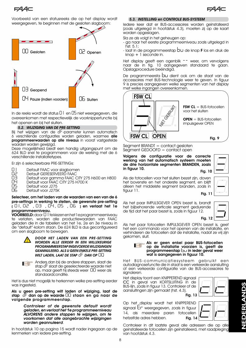
8
Voorbeeld van een statusreeks die op het display wordtweergegeven,tebeginnenmetdegeslotenslagboom:
Indereekswordtdestatus0 1 en05nietweergegeven,dieovereenkomenmetrespectievelijkdevoorknipperfunctiebijhetopenenenbijhetsluiten.
00 Gesloten 02 Openen
04 Pauze (indien voorzien)
03 Geopend
06 Sluiten
5.2.. WIJzIGING.VAN.DE.PRE-SETTINGBij het wijzigen van de dF -parameter kunnen automatisch6 verschillende configuraties worden geladen, waarmee alle programmeerwaarden op alle niveaus in vooraf vastgesteldewaardenwordengewijzigd.Deze mogelijkheid biedt een handig uitgangspunt om de6�4BLDsnel teprogrammerenvoordewerkingmetde6verschillendeinstallatietypes.
Erzijn6selecteerbarePRE-SETTINGs:
0 1 DefaultFAACvoorslagbomen02 DefaultGERESERVEERDFAAC03 DefaultvoorgammaFAACCITY�75H600enH80004 DefaultvoorFAACCITY�75H700K05 DefaultvoorJ�7506 DefaultvoorJ�75K
Selecteer, om het laden van de waarden van een van de 6 pre-settings in werking te stellen, de gewenste pre-setting ( 0 1 , 02 , 03 , 04 , 05 , 06 ) en verlaat het 1e programmeerniveau.VOORBEELD: door0 1 tekiezenenhet�eprogrammeerniveaute verlaten, worden alle productiewaarden van FAACgeladendieindetabellenvanhet�e,�een�eniveauinde“default”-kolomstaan.De6�4BLDisdusgeconfigureerdomeenslagboomtebewegen.
. DOOR. HET. LADEN. VAN. EEN. PRE-SETTING.WORDEN. ALLE. EERDER. IN. EEN. WILLEKEURIGE.PROGRAMMEERSTAP.INGEVOERDE.WIJzIGINGEN.GEANNULEERD..ALS.U.GEEN.ENKELE.PRE-SETTING.WILT.LADEN,.LAAT.DE.STAP.dF .DAN.OP.00.
Andersdanbijdeanderestappen,slaatdestapdFslaatdegeselecteerdewaardenietop,maargeefthijsteedsweer00weeralsstandaardconditie.
Hetisdusnietmogelijkteherkennenwelkepre-settingeerderwasingesteld.
Als u geen pre-setting wilt laden of wijziging, laat de stap dF dan op de waarde 00 staan en ga naar de volgende programmeerstap.
Controleer. of. de. gewenste. default. wordt.geladen,.en.verlaat.het.1e.programmeerniveau..ALVORENS. andere. stappen. te. wijzigen,. om. te.voorkomen.dat.alle.aangebrachte.wijzigingen.worden.geannuleerd.
Inhoofdstuk�0oppagina�5wordtnaderingegaanopdekenmerkenvaniederepre-setting.
5.3.. INSTELLING.en.CONTROLE.BUS-SYSTEEMIedere keer dat er BUS-accessoires worden geïnstalleerd(zoals uitgelegd in hoofdstuk 4.�), moeten zij op de kaartwordenopgeslagen.Slazealsvolgtinhetgeheugenop:-ganaarheteersteprogrammeerniveauzoalsuitgelegdin
hst.5.�;-laatindeprogrammeerstapbu deknopFlosendrukde
knop+�secondein.
Het display geeft een ogenblik -- weer, om vervolgensnaar de in fig. �0 aangegeven standaard te gaan.Opslagprocedurebeëindigd.
De programmeerstabu dient ook om de staat van deaccessoires met BUS-technologie weer te geven. In figuur9ispreciesaangegevenwelkesegmentenvanhetdisplaymetwelkeingangenovereenkomen.
Fig. 9
SegmentBRANDT=contactgeslotenSegmentGEDOOFD=contactopen
FSW CL=BUS-fotocellenvoorhetsluiten
OPEN=BUS-fotocellenimpulsgeverOPENNI
ETG
EBRU
IKT
Volgens de configuratie voor de correcte werking van het automatisch systeem moeten de drie horizontale segmenten BRANDEN, zoals in figuur 10.
Alsdefotocellenvoorhetsluitenbezetzijn,dovenhet bovenste en het onderste segment, en blijftalleen het middelste segment branden, zoals infiguur��.
Als hetpaar IMPULSGEVEROPENbezet is,brandthet bijbehorende verticale segment gedurendedetijddathetpaarbezetis,zoalsinfiguur��.
Fig. 10
Fig. 11
Fig. 12
Als het paar fotocellen IMPULSGEVER OPEN bezet is, geefheteencommandovoorhetopenenvandeinstallatie,enverhinderendefotocellendatdeinstallatie,nadatzevrijzijngekomen,sluit.
Als er geen enkel paar BUS-fotocellen op de installatie voorzien is, geeft de programmeerstapbuin ieder geval weer wat is aangegeven in figuur 10.
He t BUS -commun ica t i e s y s teem geb ru i k t eenautodiagnosefunctiedieinstaatiseenverkeerdeaansluitingof een verkeerde configuratie van de BUS-accessoires tesignaleren.HetdisplaytoonteenKNIPPERENDsignaalcc in geval van KORTSLUITING in deBUS-lijn,zoalsinfiguur��.Controleerofdeaansluitingenzijngemaakt(hst.4.�).
Op het display wordt het KNIPPERENDsignaalErweergegeven, zoals in figuur�4, als meerdere paren fotocellenhetzelfdeadreshebben.
Fig. 13
Fig. 14
Controleer in dit laatste geval alle adressen die op allegeïnstalleerdefotocellenzijngeïnstalleerd,metraadplegingvanhoofdstuk4.�.
NED
ERLA
ND
S

9
PROGRAMMERING 2e NIVEAU
Display Functie De-fault
bo MAXIMAAL AANLOOPKOPPEL:wanneer de beweging begint, draait demotormethetmaximalekoppel (ongeachthetingesteldekoppel).
Y=Actief no=Uitgeschakeld
Y
PF VOORKNIPPERFUNCTIE:hiermeekandevoorknipperfunctie,voordatde beweging begint, 5 seconden langwordeningeschakeld.
nouitgeschakeld
OCvòòriederebeweging
PAalleenaaneindepauze
CLvòòrhetsluiten
no
SC LANGZAAM SLUITEN:hiermee kan voor heel de sluitingsfase eenlageresnelheidwordeningesteld.
Y =Actief no =Uitgeschakeld
no
tr VERTRAGINGSTIJD BIJ EINDSCHAKELAAR:hiermee kan de vertragingstijd wordeningesteld (in seconden) nadat deeindschakelaarsvoorhetopenenensluitenzijningeschakeld.Regelbaar van 0 tot 10 sec. in stappen vaneenseconde.
0 0 =vertraginguitgeschakeld 1 0 =maximalevertraging
03
t WERKTIJD (time-out):Het iswenselijkeentijd intestellendie5-�0seconden langer is dan de tijd die hetautomatischsysteemnodigheeftomvandegeslotenstandnaardeopenstandtegaan,enomgekeerd.Regelbaarvan0tot59sec.instappenvaneenseconde.Vervolgensverandertdeweergaveinminutenentientallenseconden(gescheidendooreenpunt),enwordtde tijdgeregeld in stappenvan�0seconden,toteenmaximumwaardevan4.1minuten.
20
FS FAIL SAFE:Als deze functie wordt geactiveerd, is hetmogelijkeenwerkingstestvandefotocellenuit te voeren voordat het automatischsysteemenigebeweginguitvoert,ongeachtde gebruikte uitgang. Als de test niet goedafloopt, start het automatisch systeem debewegingniet.
Y=Actief no =Uitgeschakeld
no
5.4.. PROGRAMMERING.2e.NIVEAUOmtoegangtekrijgentotdePROGRAMMERINGvanhet�eNIVEAUmoetdeknopFwordeningedrukt,en,terwijlhijingedruktwordtgehouden,deknop+wordeningedrukt:• alsknop+wordtlosgelaten,verschijntdenaamvande
eerstefunctieophetdisplay.• alsookknopFwordtlosgelaten,verschijntdewaardevan
defunctieopdedisplay;dezekanwordengewijzigdmetdetoetsen+en-.
• dooropnieuwdetoetsFintedrukken(eningedrukttehouden)toontdedisplaydenaamvandevolgendefunctie,enz.,alshijwordtlosgelatenwordtdewaardeweergegeven,diekanwordengewijzigdmetdetoetsen+en-.
• aangekomenbijdelaatstefunctiezultu,alsuopnieuwFindrukt,deprogrammeringverlaten,engeefthetdisplayopnieuwdestatusvandeingangenweer.
o 1 UITGANG 1:De uitgang kan op een van de volgendefunctieswordeningesteld:
00 FAILSAFE
0 1 INDICATIELAMPJE(brandttijdensopenenenpauze,knipperttijdenssluiten,gedoofdalshetautomatischsysteemgeslotenis).
02 VERLICHTINGBOOM (uitgangactiefalsboomgeslotenis,nietactiefalsboomopenis,knipperendtijdensbeweging)
03 boomGESLOTEN
04 boom OPEN of in PAUZE, doofttijdensvoorknipperfunctiesluiten.
05 OPENINGSBEWEGINGboom,inclusiefvoorknipperfunctie.
06 SLUITINGSBEWEGINGboom,inclusiefvoorknipperfunctie.
07 boomSTAATSTIL
08 NOODGEVALboom
09 LOOP�ingeschakeld
10 LOOP�ingeschakeld
1 1 OPENvoor6�4SLAVE
12 CLOSEvoor6�4SLAVE
13 boomLOSVANSTANDAARD
14 lichtenverkeerspaal
15 zoemerverkeerspaal
16 FCAbezet
17 FCCbezet
18 tussenvergrendeling
00
P 1 POLARITEIT UITGANG 1:Hiermee kan de uitgangspolariteit wordengeconfigureerd. Y =polariteitN.C. no =polariteitN.O.
Opmerking: laat als waardeno staan alsdeuitgangalsFAIL-SAFEisingesteld(00 ).
no
o2 UITGANG 2:Zieuitgang� 03
P2 POLARITEIT UITGANG 2:Ziepolariteituitgang� no
o3 UITGANG 3:Zieuitgang� 0 1
P3 POLARITEIT UITGANG 3:Ziepolariteituitgang� no
o4 UITGANG 4 / BUS:Als hij is ingesteld op 00, is deze uitgang bedoeld voor accessoires met BUS-technologie. Raadpleeg Hoofdstuk 4.3 op pagina 5 vooruitleg.Dezeuitganglaatdemogelijkhedenuitgang�teconfigurerenongewijzigd,metuitzonderingvandefunctie 1 1 , 12,18dieinditgevalgeeneffecthebben.
00
P4 POLARITEIT UITGANG 4:Hiermee kan de uitgangspolariteit wordengeconfigureerd. Y =polariteitN.C. no =polariteit N.O. (voor BUS)
no
NED
ERLA
ND
S

�0
AS VERZOEK ASSISTENTIE (in combinatie met de volgende functies):Als deze functie wordt geactiveerd, zal deuitgangLAMPaanheteindevanhetaftellen(datkanworden ingesteldmetdevolgendetweefuncties“Programmeringcycli”)iedere�0seconden (verzoekom ingreep)ongeveer4secondenwordeningeschakeld.Ditkannuttigzijn voor het instellen van geprogrammeerdonderhoud. Y=Actief no =Uitgeschakeld
no
nc PROGRAMMERING CYCLI IN DUIZENDTALLEN:Hiermee kan het aftellen van een aantalwerkingscycli van de installatie wordeningesteld, instelbare waarde van 0 tot 99(maalduizendcycli)Deweergegevenwaardewordtaangepastnaarmatedecycliwordenuitgevoerd,enheeftdaarbijeenwisselwerkingop de waarde van nC (als nc met 99afneemt,neemtnC afmetéén).DezefunctiekanwordengebruiktincombinatiemetnC ,omhetgebruikvande installatie tecontroleren,enomgebruiktemakenvanhet“Verzoekomassistentie”.
00
nC PROGRAMMERING CYCLI IN HONDERDDUIZENDTALLEN:Hiermee kan het aftellen van een aantalwerkingscycli van de installatie wordeningesteld,instelbarewaardevan0tot99(maalhonderdduizendcycli)Deweergegevenwaardewordt aangepast naar mate de cycli wordenuitgevoerd, en heeft daarbij een wisselwerkingmetdewaardevannc .(alsnC met�afneemt,neemtnc afmet99).Dezefunctiekanwordengebruiktincombinatiemetnc , om het gebruik van de installatie tecontroleren, en om gebruik te maken van het“Verzoekomassistentie”.
0 1
h 1 WACHTTIJD LOOP 1Hiermeekandetijdvanaanwezigheidoploop�wordeningesteld.Naafloopvandezetijdijktdekaartzichzelfenhijgeefthijhetsignaal“lusvrij” (decimaalpunt van de eenheden OFF).Wanneerdekaartwordtaangezetwordteenautomatischeresetuitgevoerd.
Y=5minuten no =oneindig
no
h2 WACHTTIJD LOOP 2Hiermee kan de tijd van aanwezigheid oploop�wordeningesteld.Naafloopvandezetijd ijkt de kaart zichzelf en hij geeft hij hetsignaal“lusvrij”(decimaalpuntvandetiendenOFF).Wanneerdekaartwordtaangezetwordteenautomatischeresetuitgevoerd. Y=5minuten no =oneindig
no
St STATUS AUTOMATISCH SYSTEEM:Verlaten van de programmering, opslagvan de gegevens en terugkeer naar destatusweergavevanhethek(ziepar.5.�.).
5.5.. INSTELLING.INGEBOUWDE.LOOP.DETECTOR
De 6�4 BLD is voorzien van een ingebouwde detector vanmetalen massa’s waarmee via inductie voertuigen wordengedetecteerd.Eigenschappen:
galvanischescheidingtussendeelektronicavandedetectorendelusautomatischuitlijnenvanhetsysteemmeteennaactiveringcontinueresetvandefrequentiedriftengevoeligheidonafhankelijkvandeinductiviteitvandelusregelbarewerkfrequentievandelussenbericht“lusbezet”weergegevenmetledstatusvandelussendievaneenadreskunnenwordenvoorzienopdeuitgangenOUT�,OUT�,OUT�enOUT4
•
••••••
PuntBRANDT =LusBEZETPuntGEDOOFD =LusVRIJPuntKNIPP. =LusNIETAANGESLOTENofWORDTGEIJKT
LOOP� LOOP�
INSTELLEN GEVOELIGHEIDDoordegevoeligheidintestellenwordtvaniederkanaaldevariatievandeinductiviteitbepaalddieeenvoertuigmoetveroorzakenomdebijbehorendeuitgangvandedetectorteactiveren.Degevoeligheidwordtvooriederkanaalapartingesteldmetbehulpvande tweeparametersS 1 enS2 vanheteersteprogrammeerniveau.DaarnaastkanbijbeidedetectorendeBOOST-functiewordeningeschakeld.Ziehoofdstuk5.�.
INSTELLEN WACHTTIJDDewachttijdbegint te lopenwanneerde luswordtbezet.Alsnadatdezetijd isverstrekendelusnogsteedsbezet is,wordteennieuweautomatischeijkinguitgevoerd,waarmeedeaanwezigheidvaneenmetalenmassaopdelusdezelusnietlangeralsbezetaangeeft.Naafloopvandenieuweijkingwordtdelusals“vrij”beschouwd.Dewachttijdkanwordeningesteldmetbehulpvandetweeparametersh 1 enh2evanhet�eprogrammeerniveau.Ziehoofdstuk5.4.
Aansluiting:Sluitdedetectielussenaanzoalsaangegeveninfiguur�oppagina4:
-Klemmen� -�voor LOOP�= lusmet functieopeningdoorgang;
- Klemmen � - 4 voor LOOP � = lus met functie sluitingdoorgangen/ofbeveiligingbijsluiting.
Voornadereinformatieoverheteffectvandesignalendievandelusafkomstigzijnophetautomatischsysteem,ziedelogicatabelleninhoofdstuk��.
Om de werking van de aangesloten lussen te activeren, moet u naar het 1e programmeerniveau gaan en de stappen L1 en L2 in Y tegelijkertijd met de aangesloten lussen instellen. Als er slechts één lus is geïnstalleerd, activeer dan alleen de bijbehorende programmeerstap.Dewerkingsstatusvandeloopdetectorwordtgetoonddoormiddelvandedecimaalpuntenvanhetdisplaywanneerdestatusvanhetautomatischsysteemwordtgetoond(stapSt).IJKINGIedere keer dat de voeding naar de kaart 6�4 BLD wordtingeschakeld,geefthetdisplaydestatusvanhetautomatischsysteemweer,envoertdeingebouwdedetectoreenzelfijkingvandeaangesloten lussenuit.Voerduseen ijkinguitdoordespanningnaarde6�4BLDminstens5seconden los tekoppelen.
Deijkingwordtweergegevenophetdisplaydoordat twee punten knipperen zoals infiguur�5.
. Als.een.of.beide.magnetische.lussen.niet. is/zijn.geïnstalleerd,.blijft.de.loop.detector.constant.ijken,.zonder.dat.dit.werkingproblemen.voor.de.kaart.met.zich.meebrengt..Tijdens.de.weergave.van.de.status.van.het.automatisch.systeem.knipperen.een.of.twee.decimaalpunten.constant.
Na het ijken geven de decimaalpunten de status van delussenweer:
Fig. 15
NED
ERLA
ND
S

��
.6.. INBEDRIJFSTELLING
6.1.. CONTROLE.VAN.DE.LEDS.OP.DE.KAART
Fig. 16
6.2.. CONTROLE.STATUS.VAN.DE.BUS
Raadpleeg deze paragraaf als er BUS-fotocellen zijn geïnstalleerd, zoals aangegeven in paragraaf 4.3 op pagina 5.Ganaarhet�eprogrammeerniveauengeefdeprogrammeerstapbu ophetdisplayweer.Dezestapmoetdriehorizontalelijnenweergeven,ter bevestiging dat alle paren BUS-fotocellenonbezetzijn.Zieparagraaf5.�oppagina8voornaderedetailsoverdeweergavevandezeinrichtingen.
.7.. TEST.VAN.HET.AUTOMATISCHE.SYSTEEM
Controleer na het programmeren of de installatie goedwerkt.Controleer vooral of de kracht van het automatischsysteem goed is ingesteld, en of de daarop aangeslotenbeveiligingsvoorzieningenopcorrectewijzeingrijpen.
INSTELLEN FREQUENTIE en OPNIEUW UITBALANCEREN
De werkingsfrequentie van ieder kanaal van de detectorkanwordeningesteldoptweeniveausmetbehulpvandedip-schakelaarDS�(ziefig.�).
DIP� ON=Frequentieloop�LAAG OFF=Frequentieloop�HOOG
DIP� ON=Frequentieloop�LAAG OFF=Frequentieloop�HOOGAls een van deze dipschakelaars wordt gewijzigd, wordtaangeraden een nieuwe ijking uit te voeren. Als er tweelussen zijn geïnstalleerd, kies dan verschillende frequentiesvooriederelus.
OPMERKINGEN VOOR HET AANLEGGEN VAN DE LUSSEN
Delusmoetwordenaangelegdopminstens�5cmvanvastemetalenvoorwerpen,enminstens50cmvanbewegendemetalenonderdelen,enopnietmeerdan5cmvanhetdefinitievewegdek.Gebruikeennormaleeenpoligekabelmeteendoorsnedevan �,5mm² (als de kabel rechtstreeks wordt ingegraven,moet hij dubbel geïsoleerd zijn). Maak bij voorkeur eenvierkanteof rechthoekige lus,dooreen kabelbuis vanpvcaan te leggen of door een sleuf in de vloer te maken,zoalsaangegeveninfiguur�6(dehoekenmoetenwordenafgerondmet45°omtevoorkomendatdekabelbreekt)Legdekabelaanmethetaantalwikkelingendatindetabelisaangegeven.Detweeuiteindenvandekabelmoetenmetelkaarverwevenzijn(minstens�0keerpermeter)vandelustotaandedetector.Vermijdverbindingenindekabel(alsdatnoodzakelijkmochtzijn,lasdandedradenenverzegeldeverbindingmeteenkrimphoes),enhoudhemgescheiden
vandeelektriciteitsleidingen.Controleer, alvorens de elektronische apparatuur 6�4 BLDdefinitiefinwerkingtestellen,deactiveringsstatusvandeledsopdeapparatuur.Deze ledsgevende staat vande ingangenvande kaartweer,enzijnvangrootbelangvoordebewegingvanhetautomatischsysteem:
LEDBRANDT :contactGESLOTEN
LEDGEDOOFD :contactOPEN
In Figuur 16 is de configuratie van de standaard-leds weergegeven met het automatisch systeem GESLOTEN, klaar om te worden geopend.
De ingangen Emergency (DL5) ,STOP (DL4), Fotocellen (DL�) en Pivot(DL8) zijn beveiligingsingangen met N.C.-contacten (normaalgesloten),debijbehorendeledsBRANDENdus
DeledsFCAenFCCvertegenwoordigendeN.C.-contactenvandeeindschakelaarsdie,alszewordenbezet,opengaan,endaarmeedebijbehorendeleddoven:
Methetautomatisch
systeemGESLOTEN FCCBEZET
MethetautomatischsysteemGEOPEND
FCABEZET
Omtrek Lus
N° Wikkelingen
minderdan�m 6
van�tot4m 5
van4tot6m 4
van6tot��m �
meerdan��m �
mm
mm
Fig. 16
NED
ERLA
ND
S

��
1 OFF2 OFF
Fig. 17
.8.. CONFIGURATIES.MASTER-SLAVE
Alsdeinstallatietweetegenoverstaandeslagbomenheeftdietegelijkertijdmoetenwordenbediendomdedoorgangteopenen/sluiten,wordteenvandehieronderweergegevenaansluitingsdiagrammengebruikt,afhankelijkvandeelektronischekaartendiewordengebruiktomdeslagbomentebewegen.
MetdeMASTER-apparatuurwordtbedoelddeelektronischekaartwaaropalle impulsgeversenveiligheidsinrichtingenzijnaangesloten.MetSLAVE-apparatuurwordtbedoelddeelektronischekaartdiewordtbedienddoordeMASTERviade impulsingangen,terwijldebeveiligingsingangenzijnkortgesloten.
a ...PROGRAMMERING..1e.NIVEAU
LO = Cb ...PROGRAMMERING..3e.NIVEAU
03 = Yc ...PROGRAMMERING..1e.NIVEAU
LO = CU
NED
ERLA
ND
S

��
Deprogrammeringenvanhet�eniveauwordtalleengebruiktalsdereedsinhetgeheugenaanwezigebedrijfslogica’sverderaandewensenvandegebruikermoetenwordenaangepast.
Controleer,.alvorens.wijzigingen.aan.te.brengen.in.dit.niveau,.of.u.goed.heeft.begrepen.wat.de.aard.is.van.de.stappen.die.u.wilt.veranderen,.en.wat.de.invloed.daarvan.op.het.automatisch.systeem.is.
OmtoegangtekrijgentotdePROGRAMMERING�eNIVEAUmoet knop F ingedrukt worden gehouden en tegelijkertijd knop + ongeveer 10 seconden worden ingedrukt.HetgebruikvandetoetsenF,+en–ishetzelfdealsbijdeanderetweeprogrammeerniveaus.
PROGRAMMERING 3e NIVEAU 10 sec
D. Functie Instelling
0 1 Alsdezefunctiewordtgeactiveerdwordtdeboomnadepauzetijdautomatisch gesloten. Y=automatischesluitingno=uitgeschakeld
02 Als deze functie wordt geactiveerd, heeft men een werking met twee afzonderlijke ingangen:OPENvoorhetopenenenCLOSEvoorhetsluiten.
Y=werkingmet�ingangenno=uitgeschakeld
03Activeringvandeherkenningvandeniveausvandeingangen OPEN en CLOSE (commando ingedrukt gehouden).D.w.z.,dekaartherkenthetniveau(bijvoorbeeldalsOPENingedruktwordt gehouden en op STOP wordt gedrukt, gaat het automatische systeem, wanneerlaatstgenoemdewordtlosgelaten,verdermetopenen).Als03isgedeactiveerd,geeftdekaartuitsluitendeencommandovooreenmanoeuvrealsdeingangwordtgewijzigd.
Y=herkenningniveauno=herkenningwijzigingstatus
04 ActiveringopeningmetDEADMAN (commando steeds ingedrukt).AlshetcommandoOPENwordtlosgelaten,wordtdewerkinggeblokkeerd
Y=actiefno=uitgeschakeld
05Alsdezefunctiewordtgeactiveerd,stopthetcommando OPENdebewegingtijdenshetopenen.Alsdeparameter06nois,ishetsysteemgereedomtewordengeopend.Alsdeparameter06Yis,ishetsysteemgereedomtewordengesloten.
Y=blokkeerttijdensopeningno=uitgeschakeld
06Alsdezefunctiewordtgeactiveerd,keerthetcommando OPENdebewegingtijdenshetopenenom.Alsdeparameters05en06nozijn,heeftOPENgeeneffecttijdenshetopenen.
Y = keert beweging tijdensopeningom
no=uitgeschakeld
07Alsdezefunctiewordtgeactiveerd,blokkeerthetcommando OPENtijdensdepauzedewerking.Alsdeparameters07en08nozijn,zorgtOPENdatdepauzetijdopnieuwbeginttelopen.
Y=blokkeerttijdensdepauzeno=uitgeschakeld
08 Alsdezefunctiewordtgeactiveerd,zorgthetcommando OPENtijdensdepauzevoorsluiting.Alsdeparameters07en08nozijn,zorgtOPENdatdepauzetijdopnieuwbeginttelopen.
Y=sluittijdenspauzeno=uitgeschakeld
09 Alsdeze functiewordtgeactiveerd,blokkeerthetcommando OPEN tijdenshet sluitendewerking;zoniet,dankeerthijdebewegingom.
Y=blokkeertno=keertom
10 ActiveringsluitingmetDEADMAN(commandosteedsingedrukt).Alshetcommando CLOSEwordtlosgelaten,wordtdewerkinggeblokkeerd.
Y=actiefno=uitgeschakeld
1 1 Alsdezefunctiewordtgeactiveerd,heefthetcommando CLOSEprioriteitbovenOPEN;zoniet,danheeftOPENprioriteitbovenCLOSE.
Y=actiefno=uitgeschakeld
12Als deze functie wordt geactiveerd, geeft het commando CLOSE het commandovoorsluitingwanneerhijwordt losgelaten.ZolangalsCLOSEactief isblijftdeeenheidvoorknipperenbijsluiting.
Y=sluitnaloslatenno=sluitonmiddellijk
13Alsdezefunctiewordtgeactiveerd,blokkeerthetcommando CLOSEtijdenshetopenendewerking;zoniet,dangeefthetCLOSEhetcommandoomdebewegingonmiddellijk,ofnadatdeopeningsbewegingisbeëindigd,omtekeren(zieookparameter14)
Y=CLOSEblokkeertno=CLOSEkeertom
14Alsdezefunctiewordtgeactiveerdenalsdeparameter13nois,geefthetcommando CLOSEhetcommandovooronmiddellijkesluitingnadatdeopeningscyclusisbeëindigd(slaatCLOSEopinhetgeheugen).Alsdeparameters13en14nonozijn,geeftCLOSEhetcommandovooronmiddellijkesluiting.
Y=sluitnaeindeopeningsbeweging
no=onmiddellijkesluiting
15AlsdezefunctiewordtgeactiveerdmethetsysteemgeblokkeerddooreenSTOP,beweegteen daaropvolgend OPEN-commandodeboomindetegengestelderichting.Alsdeparameter15nois,sluithijaltijd.
Y = beweegt de boom integengestelderichting
no=sluitaltijd
16Alsdezefunctiewordtgeactiveerd,blokkerendeVEILIGHEIDSVOORZIENINGEN SLUITINGtijdenshetsluitendebewegingenstaanzetoedatdebewegingwordthervatwanneerzevrijkomen;zoniet,dankerenzedebewegingonmiddellijkominopening.
Y=sluitbijvrijkomenno=keertonmiddellijkom
17Als deze functie wordt geactiveerd, geven de VEILIGHEIDSVOORZIENINGEN SLUITINGhetcommandovoorsluitingwanneerzevrijkomen.(zieookparameter18).
Y=sluitbijvrijkomenvanFSWno=uitgeschakeld
18 Alsdezefunctiewordtgeactiveerd,enalsdeparameter17Yis,wachtdeeenheidtotdeopeningscyclusbeëindigdisalvorenshetsluitingscommandouittevoerendatdoordeVEILIGHEIDSINRICHTINGEN SLUITINGisgegeven.
Y=sluitnaeindeopeningsbeweging
no=uitgeschakeld
19Alsdezefunctiewordtgeactiveerd,blokkeertLOOP2 tijdenshetsluitendebeweging,enstaathijtoedatdebewegingwordthervatwanneerhijvrijkomt;zoniet,dankeerthijdebewegingonmiddellijkominopening.
Y=sluitbijvrijkomenno=keertonmiddellijkom
20 Alsdezefunctiewordtgeactiveerd,geeftLOOP2hetcommandovoorsluitingwanneerhijvrijkomt(zieookparameter21).
Y=sluitalsLOOP�vrijisno=uitgeschakeld
2 1 Alsdezefunctiewordtgeactiveerd,enalsdeparameter20Yis,wachtdeeenheidtotdeopeningscyclusbeëindigdisalvorenshetsluitingscommandouittevoerendatdoorLOOP2isgegeven.
Y=sluitnaeindeopeningsbeweging
no=uitgeschakeld
22 Als deze functie wordt geactiveerd, verkrijgen de commando’s van LOOP1 prioriteitbovendievanLOOP2.
Y=actiefno=uitgeschakeld
.9.. PROGRAMMERING.3e.NIVEAU
NED
ERLA
ND
S

�4
D. Functie Instelling
23De LOOP 1 geeft het commando voor het openen en sluit daarna de boom als hijonbezetis(nuttigalshetvoertuigachteruitrijdtmetopeenvolgendeloops).AlshijwordtuitgeschakeldalsLOOP�vrijkomt,wordtdeboomnietgesloten.
Y=sluitalsLOOP�vrijisno=uitgeschakeld
24 NIET GEBRUIKT /
25Functie A.D.M.A.P.als deze functie wordt geactiveerd, werken de veiligheidsvoorzieningen conform de Franse regelgeving.
Y=actiefno=uitgeschakeld
26Alsdezefunctiewordtgeactiveerd,blokkerendeVEILIGHEIDSVOORZIENINGEN SLUITINGtijdenshetsluitendebewegingenkerenzedebewegingomwanneerzevrijkomen;zoniet,dankerenzedebewegingonmiddellijkom.
Y=blokkeertenkeertombijvrijkomen
no=keertonmiddellijkom.
27 GEEN EFFECT /
A 1VOORKNIPPERFUNCTIE:Hiermee kan, met stappen van � sec., de gewenste duur van de voorknipperfunctiewordeningesteld,vaneenminimumvan0toteenmaximumvan10 seconden
05
A2TIME-OUT OMKERING BIJ SLUITING:Als deze functie wordt geactiveerd, kan tijdens het sluiten worden besloten om debewegingomtekerenofteblokkerennahetverstrijkenvandetime-out(nietbereikenvandeeindschakelaarvoorhetsluiten).
Y=omkeringno=blokkering
A3OPENEN BIJ HET AANZETTEN:Alsergeenspanningis,kan,wanneerdezefunctieisingeschakeld,zodradespanningweer wordt ingeschakeld, een openingscommando worden gegeven (alleen als hetautomatischesysteemnietgeslotenis,FCCvrij).
Y=openingno=blijftstilstaan
A4TIJD ACTIVERING PRESSOSTAAT FAAC CITY (J5):DitisdetijdwaarnadeeenheidhetsignaalafkomstigvandepressostaatalsEINDAANSLAGVOORSLUITINGbeschouwt.Regelbaar van0 tot59 sec. in stappen van een seconde. Vervolgens verandert deweergave in minuten en tientallen seconden (gescheiden door een punt), tot eenmaximumwaardevan4,1minuten.
4.0
A5DEACTIVERING PRESSOSTAAT VERKEERSPAAL BIJ BEGIN BEWEGING: Vooreencorrectewerkingvandeverkeerspaalmoetdebedieningvandepressostaataanhetbeginvandestijgingsmanoeuvrewordengedeactiveerd(duur0,4seconden).SteldezefunctieinopY metverkeerspalen.
Y=pressostaatgedeactiveerdbijaanloop
no=pressostaataltijdactief
A6BEDIENING VOEDING ELEKTROKLEP VERKEERSPALEN (klemmen 22-23):FAACCITYK-J�75K:uitgangelektroklepnormaalnietgevoed-gevoedtijdensdaling.FAAC CITY - J275 standaard: uitgangelektroklepnormaalgevoed-nietgevoedtijdensdaling.
Y=bijFAACCITYK/J�75Kno=bijFAACCITYstandaardenJ�75
A7 POLARITEIT EINDSCHAKELAAR VOOR OPENING:Configuratievanhetcontactvandeeindschakelaar
Y=polariteitNOno=polariteitNC
A8 POLARITEIT EINDSCHAKELAAR VOOR SLUITING:Configuratievanhetcontactvandeeindschakelaar
Y=polariteitNOno=polariteitNC
A9ACTIVERING PRESSOSTAAT FAAC CITY (J5):Herkenning van het contact PRESSOSTAAT als veiligheidsvoorziening tijdens de eerstestijgfaseenalseindschakelaarnaafloopvandeactiveringstijdvandepressostaatFAACCITY(parameterA4):
Y=WerkingvoorFAACCITYno = Standaardwerking
eindschakelaar
b0PRESSOSTAAT ALLEEN VOOR VEILIGHEIDSVOORZIENING VOOR VERKEERSPALEN (klemmen 7 - GND):
HerkenningvanhetcontactFOTOCELalsPRESSOSTAATalsveiligheidsvoorziening.(hetcontactwordtaanhetbeginvandebewegingenaanheteindevandestijginggenegeerd)
Y = Werking van depressostaat uitsluitend alsveiligheidsvoorzieningno = Standaardwerking
fotocellen
b 1 VERTRAGING INGREEP FUNCTIE HOLD CLOSE / HOLD OPEN:VertragingstijdinhetactiverenvandefunctieHOLD CLOSE / HOLD OPEN(zieparametersb�enb4).Detijdbeginttelopenwanneerdebetreffendeeindschakelaarisbereikt.Alsaanheteindevandeingesteldetijddeeindschakelaarperongelukvrijblijkt tezijn,wordtdefunctieHOLD CLOSE / HOLD OPENgeactiveerd. 00=onmiddellijkeactiveringvanHOLD CLOSE / HOLD OPEN01 tot99=resterendeminutenvoordatHOLD CLOSE / HOLD OPENwordtgeactiveerd
30
b2 NIET WIJZIGEN 30b3 HOLD CLOSE FUNCTIE:
Wanneerdeeindschakelaarvoorhetsluitenperongelukwordtverlaten,geeftdekaartau-tomatischeenbewegingscommandovan�sec.omdepositieteherstellen;alsindezetijddeeindschakelaarvoorhetsluitennietwordt ingeschakeld,wordthetautomatischesysteemvoordemaximalewerkingtijd“t”geactiveerd,zie�°NIV.PROGRAMMERING:
Y=actiefno=uitgeschakeld
b4 HOLD OPEN FUNCTIE:Wanneerdeeindschakelaarvoorhetopenenperongelukwordtverlaten,geeftdekaartautomatischeenbewegingscommandovan�sec.omdepositieteherstellen;alsindezetijddeeindschakelaarvoorhetopenennietwordtingeschakeld,wordthetautomatischesysteem voordemaximale werkingtijd “t” geactiveerd, zie �° NIV. PROGRAMMERING: (parameterA3opYwordtaangeradenalsparameterb3isingesteldopY)
Y=actiefno=uitgeschakeld
NED
ERLA
ND
S
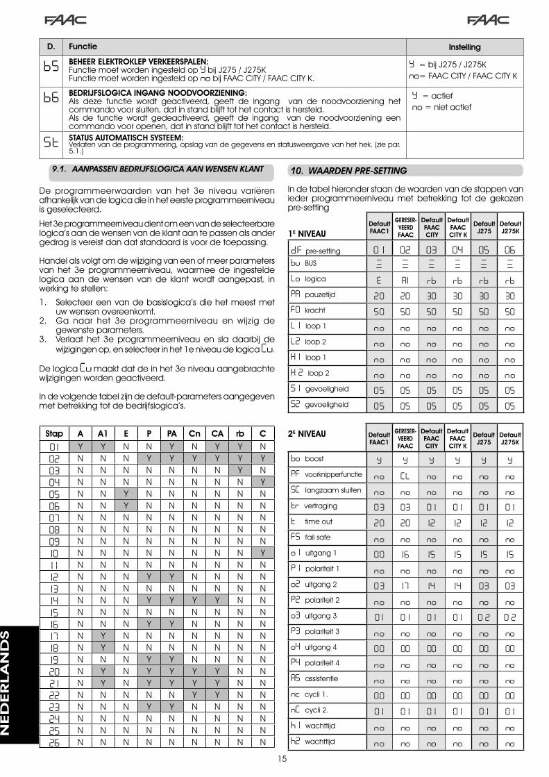
�5
9.1.. AANPASSEN.BEDRIJFSLOGICA.AAN.WENSEN.KLANT
De programmeerwaarden van het �e niveau variërenafhankelijkvandelogicadieinheteersteprogrammeerniveauisgeselecteerd.
Het�eprogrammeerniveaudientomeenvandeselecteerbarelogica’saandewensenvandeklantaantepassenalsandergedragisvereistdandatstandaardisvoordetoepassing.
Handelalsvolgtomdewijzigingvaneenofmeerparametersvan het �e programmeerniveau, waarmee de ingesteldelogica aan de wensen van de klant wordt aangepast, inwerkingtestellen:
Selecteereenvandebasislogica’sdiehetmeestmetuwwensenovereenkomt.Ga naar het �e programmeerniveau en wijzig degewensteparameters.Verlaat het �e programmeerniveau en sla daarbij dewijzigingenop,enselecteerinhet�eniveaudelogicaCu.
DelogicaCumaaktdatdeinhet�eniveauaangebrachtewijzigingenwordengeactiveerd.
Indevolgendetabelzijndedefault-parametersaangegevenmetbetrekkingtotdebedrijfslogica’s.
�.
�.
�.
Stap A A1 E P PA Cn CA rb C
0 1 Y Y N N Y N Y Y N02 N N N Y Y Y Y Y Y03 N N N N N N N Y N04 N N N N N N N N Y05 N N Y N N N N N N06 N N Y N N N N N N07 N N N N N N N N N08 N N N N N N N N N09 N N N N N N N N N10 N N N N N N N N Y1 1 N N N N N N N N N12 N N N Y Y N N N N13 N N N N N N N N N14 N N N Y Y Y Y N N15 N N N N N N N N N16 N N N Y Y N N N N17 N Y N N N N N N N18 N Y N N N N N N N19 N N N Y Y N N N N20 N Y N Y Y Y Y N N2 1 N Y N Y Y Y Y N N22 N N N N N Y Y N N23 N N N Y Y N N N N24 N N N N N N N N N25 N N N N N N N N N26 N N N N N N N N N
.10.. WAARDEN.PRE-SETTING
Indetabelhieronderstaandewaardenvandestappenvanieder programmeerniveau met betrekking tot de gekozenpre-setting
1E NIVEAU
2E NIVEAU
b5 BEHEER ELEKTROKLEP VERKEERSPALEN:FunctiemoetwordeningesteldopYbijJ�75/J�75KFunctiemoetwordeningesteldopnobijFAACCITY/FAACCITYK.
Y=bijJ�75/J�75Kno=FAACCITY/FAACCITYK
b6 BEDRIJFSLOGICA INGANG NOODVOORZIENING:Als deze functie wordt geactiveerd, geeft de ingang van de noodvoorziening hetcommandovoorsluiten,datinstandblijfttothetcontactishersteld.Als de functie wordt gedeactiveerd, geeft de ingang van de noodvoorziening eencommandovooropenen,datinstandblijfttothetcontactishersteld.
Y=actiefno=nietactief
St STATUS AUTOMATISCH SYSTEEM:Verlatenvandeprogrammering,opslagvandegegevensenstatusweergavevanhethek.(ziepar.5.�.)
D. Functie Instelling
Default FAAC1
GERESER-VEERD FAAC
Default FAAC CITY
Default FAAC CITY K
Default J275
Default J275K
dF pre-setting 0 1 02 03 04 05 06bu BUS
Lo logica E A1 rb rb rb rbPA pauzetijd 20 20 30 30 30 30FO kracht 50 50 50 50 50 50L 1 loop� no no no no no noL2 loop� no no no no no noH 1 loop� no no no no no noH 2 loop� no no no no no noS 1 gevoeligheid 05 05 05 05 05 05S2 gevoeligheid 05 05 05 05 05 05
bo boost Y Y Y Y Y YPF voorknipperfunctie no CL no no no noSC langzaamsluiten no no no no no notr vertraging 03 03 0 1 0 1 0 1 0 1t timeout 20 20 12 12 12 12FS failsafe no no no no no noo 1 uitgang� 00 16 15 15 15 15P 1 polariteit� no no no no no noo2 uitgang� 03 17 14 14 03 03P2 polariteit� no no no no no noo3 uitgang� 0 1 0 1 0 1 0 1 0 2 0 2P3 polariteit� no no no no no noo4 uitgang4 00 00 00 00 00 00P4 polariteit4 no no no no no noA5 assistentie no no no no no nonc cycli�. 00 00 00 00 00 00nC cycli�. 0 1 0 1 0 1 0 1 0 1 0 1h 1 wachttijd no no no no no noh2 wachttijd no no no no no no
Default FAAC1
GERESER-VEERD FAAC
Default FAAC CITY
Default FAAC CITY K
Default J275
Default J275K
NED
ERLA
ND
S

�6
____________________________________________________
_____________________________________________________
________________________________________________________________________________________________________
1918
1617
1514
1213
1011
89
67
45
23
1
OPEN A
STOP
LOOP 1
LOOP 2
LOOP 2
LOOP 1
CLOSE
FSW
EMERGENCY
OUT 1
OUT 2
OUT 4
OUT 3
GND
GND
GND
+24 V
+24 V
OUT 3
J119
1816
1715
1412
1310
118
96
74
52
31
OPEN A
STOP
LOOP 1
LOOP 2
LOOP 2
LOOP 1
CLOSE
FSW
EMERGENCY
OUT 1
OUT 2
OUT 4
OUT 3
GND
GND
GND
+24 V
+24 V
OUT 3
J119
1816
1715
1412
1310
118
96
74
52
31
OPEN A
STOP
LOOP 1
LOOP 2
LOOP 2
LOOP 1
CLOSE
FSW
EMERGENCY
OUT 1
OUT 2
OUT 4
OUT 3
GND
GND
GND
+24 V
+24 V
OUT 3
J1
.11.. OPMERKINGEN
Metdefunctietussenblokkeringkunnendetweeslagbomeninlijnbediendworden(ziefig.)zodathetopenenvandeeneslagboomondergeschiktisaanhetsluitenvandeandere.Dewerkingkanineenenkelerichtingofintweerichtingenzijn.
.12.. AANSLUITING.TUSSENBLOKKERING
Fig. 18
08 no no no no no no09 no no no no no no10 no no no no no no1 1 no no no no no no12 no no no no no no13 no no no no no no14 no no no no no no15 no no no no no no16 no no no no no no17 no Y no no no no18 no Y no no no no19 no no no no no no20 no Y no no no no2 1 no Y no no no no22 no no no no no no23 no no no no no no24 no no no no no no25 no no no no no no26 no no no no no no27 no no no no no noA 1 05 0 1 05 05 05 05A2 no no no no no noA3 no no no no no noA4 4 .0 4 .0 04 04 4 .0 4 .0A5 no no Y Y Y YA6 no no no Y no YA7 no no Y Y no noA8 no no no Y no noA9 no no Y Y no nob0 no no no no Y Yb 1 00 00 30 30 30 30b2 30 30 30 30 30 30b3 no no Y Y Y Yb4 no no no no no nob5 no no no no Y Yb6 no no no no no no
0 1 no Y Y Y Y Y02 no no Y Y Y Y03 no no Y Y Y Y04 no no no no no no05 Y no no no no no06 Y no no no no no07 no no no no no no
Default FAAC1
GERESER-VEERD FAAC
Default FAAC CITY
Default FAAC CITY K
Default J275
Default J275K
3E NIVEAU
BijgekoppeldeslagbomenmoetOUT�TUSSENBLOKKERINGopparameter�8(ziePROG.�°NIVEAU)opbeidekaarteningesteldenaangeslotenwordenzoalsinfig.�8
NED
ERLA
ND
S

�7
Tab. 1/b
Tab. 1/a
LOGICA “A” IMPULSEN
STATUS AUTOMATISCH SYSTEEM OPEN A CLOSE STOP FSW LOOP 1 LOOP 2
GESLOTENgaatopenen
sluitweernadepauzetijd
geeneffectgeeneffect
(openingonderdrukt)
geeneffectgaatopenen
sluitweernadepauzetijd
geeneffect
GAAT OPEN geeneffectkeertbewegingonmiddellijkomengaatdicht
blokkeertdewerking geeneffect geeneffect geeneffect
GEOPEND IN PAUZEdepauzetijd
begintopnieuwtelopen
gaatdicht blokkeertdewerking
depauzetijdbegintopnieuw
telopen(sluitingonderdrukt)
depauzetijdbegintopnieuwte
lopen
depauzetijdbegintopnieuw
telopen(sluitingonderdrukt)
GAAT DICHTkeertbeweging
onmiddellijkominopening
geeneffect blokkeertdewerking
keertbewegingonmiddellijkom
inopening
keertbewegingonmiddellijkomin
opening
keertbewegingonmiddellijkom
inopening
GEBLOKKEERD gaatdicht gaatdichtgeeneffect
(openingensluitingonderdrukt)
geeneffect(sluitingonderdrukt)
gaatopenensluitweernade
pauzetijdgeeneffect
(sluitingonderdrukt)
LOGICA “A1” IMPULSEN
STATUS AUTOMATISCH SYSTEEM OPEN A CLOSE STOP FSW LOOP 1 LOOP 2
GESLOTENgaatopenen
sluitweernadepauzetijd
geeneffectgeeneffect
(openingonderdrukt)
geeneffectgaatopenen
sluitweernadepauzetijd
geeneffect
GAAT OPEN geeneffectkeertbewegingonmiddellijkomengaatdicht
blokkeertdewerking
gaataaneindeopening
onmiddellijkdicht
geeneffectgaataan
eindeopeningonmiddellijk
dicht
GEOPEND IN PAUZEdepauzetijd
begintopnieuwtelopen
gaatdicht blokkeertdewerking gaatdicht
depauzetijdbegintopnieuwte
lopengaatdicht
GAAT DICHTkeertbeweging
onmiddellijkominopening
geeneffect blokkeertdewerking
keertbewegingonmiddellijkom
inopening
keertbewegingonmiddellijkominopening,sluitnaeindepauze
keertdebewegingonmiddellijkominopening,sluit
weerwanneerdeopeningsmanoeuvre
isbeëindigd
GEBLOKKEERD gaatdicht gaatdichtgeeneffect
(openingensluitingonderdrukt)
geeneffect(sluitingonderdrukt)
gaatopenensluitweernade
pauzetijdgeeneffect
(sluitingonderdrukt)
LOGICA “E” IMPULSEN
STATUS AUTOMATISCH SYSTEEM OPEN A CLOSE STOP FSW LOOP 1 LOOP 2
GESLOTEN gaatopen geeneffectgeeneffect
(openingonderdrukt)
geeneffect gaatopen geeneffect
GAAT OPEN blokkeertdewerking
keertbewegingonmiddellijkomengaatdicht
blokkeertdewerking geeneffect geeneffect geeneffect
GEOPEND gaatdicht gaatdicht geeneffect(sluitingonderdrukt)
geeneffect(sluitingonderdrukt) gaatdicht geeneffect
(sluitingonderdrukt)
GAAT DICHTkeertbeweging
onmiddellijkominopening
geeneffect blokkeertdewerking
keertbewegingonmiddellijkom
inopening
keertbewegingonmiddellijkomin
opening
keertbewegingonmiddellijkom
inopening
GEBLOKKEERD gaatdicht gaatdichtgeeneffect
(openingensluitingonderdrukt)
geeneffect(sluitingonderdrukt) gaatopen geeneffect
(sluitingonderdrukt)
Tussenhaakjesdeeffectenopdeandereingangenmetactieveimpuls
.13.. TABELLEN.MET.BEDRIJFSLOGICA’S
Tab. 1/c
NED
ERLA
ND
S

�8
Tab. 1/d
Tab. 1/e
Tab. 1/f
LOGICA “P” IMPULSEN
STATUS AUTOMATISCH SYSTEEM OPEN A CLOSE STOP FSW LOOP 1 LOOP 2
GESLOTEN gaatopen geeneffectgeeneffect
(openingonderdrukt)
geeneffect
gaatopenengaatdichtnadatde
openingsmanoeuvreisbeëindigd,indien
onbezet
geeneffect
GAAT OPEN geeneffectgaataan
eindeopeningonmiddellijk
dicht
blokkeertdewerking geeneffect geeneffect
gaataaneindeopening
onmiddellijkdicht
GEOPENDgeeneffect
(sluitingonderdrukt)
gaatdichtgeeneffect
(sluitingonderdrukt)
geeneffect(sluiting
onderdrukt)verhindertdesluiting gaatdicht
GAAT DICHTkeertbeweging
onmiddellijkominopening
geeneffect blokkeertdewerking
blokkeertengaatverdermetsluitenzodrahij
vrijkomt
keertbewegingonmiddellijkominopening,
gaatdichtnadatdeopeningsmanoeuvreis
beëindigd,indienonbezet
blokkeertengaatverdermetsluitenzodrahijvrijkomt
GEBLOKKEERD gaatopen gaatdichtgeeneffect
(openingensluitingonderdrukt)
geeneffect(sluiting
onderdrukt)
gaatopenengaatdichtnadatde
openingsmanoeuvreisbeëindigd,indien
onbezet
geeneffect(sluiting
onderdrukt)
Tussenhaakjesdeeffectenopdeandereingangenmetactieveimpuls
LOGICA “PA” IMPULSEN
STATUS AUTOMATISCH SYSTEEM OPEN A CLOSE STOP FSW LOOP 1 LOOP 2
GESLOTENgaatopenen
sluitweernadepauzetijd
geeneffectgeeneffect
(openingonderdrukt)
geeneffect
gaatopenengaatdichtnadatde
openingsmanoeuvreisbeëindigd,indien
onbezet
geeneffect
GAAT OPEN geeneffectgaataan
eindeopeningonmiddellijk
dicht
blokkeertdewerking geeneffect geeneffect
gaataaneindeopening
onmiddellijkdicht
GEOPEND IN PAUZEdepauzetijd
begintopnieuwtelopen
gaatdicht blokkeertdewerking
depauzetijdbegintopnieuw
telopen(sluitingonderdrukt)
depauzetijdbegintopnieuwte
lopengaatdicht
GAAT DICHTkeertbeweging
onmiddellijkominopening
geeneffect blokkeertdewerking
blokkeertengaatverdermetsluitenzodrahij
vrijkomt
keertbewegingonmiddellijkomin
opening,gaatdichtnadatdeopeningsmanoeuvreisbeëindigd,indienonbezet
blokkeertengaatverdermetsluitenzodrahij
vrijkomt
GEBLOKKEERDgaatopenen
sluitweernadepauzetijd
gaatdichtgeeneffect
(openingensluitingonderdrukt)
geeneffect(sluiting
onderdrukt)
gaatopenengaatdichtnadatde
openingsmanoeuvreisbeëindigd,indien
onbezet
geeneffect(sluiting
onderdrukt)
LOGICA “Cn” IMPULSEN
STATUS AUTOMATISCH SYSTEEM OPEN A CLOSE STOP FSW LOOP 1 LOOP 2
GESLOTEN gaatopen geeneffectgeeneffect
(openingonderdrukt)
geeneffect gaatopen geeneffect
GAAT OPEN geeneffectgaataan
eindeopeningonmiddellijk
dicht
blokkeertdewerking geeneffect geeneffect
gaataaneindeopening
onmiddellijkdicht
GEOPENDgeeneffect
(sluitingonderdrukt)
gaatdichtgeeneffect
(sluitingonderdrukt)
geeneffect(sluiting
onderdrukt)geeneffect gaatdicht
GAAT DICHTkeertbeweging
onmiddellijkominopening
geeneffect blokkeertdewerking
keertbijhetopenenomensluitnade
pauzetijd
keertbewegingonmiddellijkomin
opening
keertbewegingonmiddellijkom
inopening
GEBLOKKEERD gaatopen gaatdichtgeeneffect
(openingensluitingonderdrukt)
geeneffect(sluiting
onderdrukt)gaatopen
geeneffect(sluiting
onderdrukt)
NED
ERLA
ND
S

�9
Tab. 1/i
Tab. 1/g
Tab. 1/h
LOGICA “CA” IMPULSEN
STATUS AUTOMATISCH SYSTEEM OPEN A CLOSE STOP FSW LOOP 1 LOOP 2
GESLOTENgaatopenen
sluitweernadepauzetijd
geeneffectgeeneffect
(openingonderdrukt)
geeneffectgaatopenen
sluitweernadepauzetijd
geeneffect
GAAT OPEN geeneffectgaataan
eindeopeningonmiddellijk
dicht
blokkeertdewerking geeneffect geeneffect
gaataaneindeopening
onmiddellijkdicht
GEOPEND IN PAUZEdepauzetijd
begintopnieuwtelopen
gaatdicht blokkeertdewerking
depauzetijdbegintopnieuw
telopen(sluitingonderdrukt)
depauzetijdbegintopnieuwte
lopengaatdicht
GAAT DICHTkeertbeweging
onmiddellijkominopening
geeneffect blokkeertdewerking
keertbijhetopenenomensluitnade
pauzetijd
keertbewegingonmiddellijkomin
opening
keertbewegingonmiddellijkom
inopening
GEBLOKKEERDgaatopenen
sluitweernadepauzetijd
gaatdichtgeeneffect
(openingensluitingonderdrukt)
geeneffect(sluiting
onderdrukt)
gaatopenensluitweernade
pauzetijd
geeneffect(sluiting
onderdrukt)
LOGICA “rb” IMPULSEN
STATUS AUTOMATISCH SYSTEEM OPEN A CLOSE STOP FSW LOOP 1 LOOP 2
GESLOTENgaatopenen
sluitweernadepauzetijd
geeneffectgeeneffect
(openingonderdrukt)
geeneffectgaatopenen
sluitweernadepauzetijd
geeneffect
GAAT OPEN geeneffectkeertbewegingonmiddellijkomengaatdicht
blokkeertdewerking geeneffect geeneffect geeneffect
GEOPEND IN PAUZEdepauzetijd
begintopnieuwtelopen
gaatdicht blokkeertdewerking
depauzetijdbegintopnieuw
telopen(sluitingonderdrukt)
depauzetijdbegintopnieuwte
lopen
depauzetijdbegintopnieuw
telopen(sluitingonderdrukt)
GAAT DICHTkeertbeweging
onmiddellijkominopening
geeneffect blokkeertdewerking
keertbewegingonmiddellijkom
inopening
keertbewegingonmiddellijkomin
opening
keertbewegingonmiddellijkom
inopening
GEBLOKKEERDgaatopenen
sluitweernadepauzetijd
gaatdichtgeeneffect
(openingensluitingonderdrukt)
geeneffect(sluiting
onderdrukt)
gaatopenensluitweernade
pauzetijd
geeneffect(sluiting
onderdrukt)
Tussenhaakjesdeeffectenopdeandereingangenmetactieveimpuls
LOGICA “C” COMMANDO’S GEACTIVEERD IMPULSEN
STATUS AUTOMATISCH SYSTEEM OPEN A CLOSE STOP FSW LOOP 1 LOOP 2
GESLOTEN gaatopen geeneffectgeeneffect
(openingonderdrukt)
geeneffect geeneffect geeneffect
GAAT OPEN / geeneffect blokkeertdewerking geeneffect geeneffect geeneffect
GEOPENDgeeneffect
(sluitingonderdrukt)
gaatdicht blokkeertdewerking geeneffect
geeneffect(sluiting
onderdrukt)
geeneffect(sluiting
onderdrukt)
GAAT DICHTkeertbeweging
onmiddellijkominopening
/ blokkeertdewerking
blokkeertdewerking
blokkeertdewerking
blokkeertdewerking
GEBLOKKEERD gaatopen gaatdichtgeeneffect
(openingensluitingonderdrukt)
geeneffect(sluiting
onderdrukt)
geeneffect(sluiting
onderdrukt)
geeneffect(sluiting
onderdrukt)
NED
ERLA
ND
S

Le descrizioni e le illustrazioni del presente manuale non sono impegnative. La FAAC si riserva il diritto, lasciando inalterate le caratteristiche essenziali dell’apparecchiatura, di apportare in qualunque momento e senza impegnarsi ad aggiornare la presente pubblicazione, le modifiche che essa ritiene convenienti per miglioramenti tecnici o per qualsiasi altra esigenza di carattere costruttivo o commerciale.
The descriptions and illustrations contained in the present manual are not binding. FAAC reserves the right, whilst leaving the main features of the equipments unaltered, to undertake any modifications it holds necessary for either technical or commer-cial reasons, at any time and without revising the present publication.
Les descriptions et les illustrations du présent manuel sont fournies à titre indicatif. FAAC se réserve le droit d’apporter à tout moment les modifications qu’elle jugera utiles sur ce produit tout en conservant les caractéristiques essentielles, sans devoir pour autant mettre à jour cette publication.
Die Beschreibungen und Abbildungen in vorliegendem Handbuch sind unverbindlich. FAAC behält sich das Recht vor, ohne die wesentlichen Eigenschaften dieses Gerätes zu verändern und ohne Verbindlichkeiten in Bezug auf die Neufassung der vorliegenden Anleitungen, technisch bzw. konstruktiv/kommerziell bedingte Verbesserungen vorzunehmen.
Las descripciones y las ilustraciones de este manual no comportan compromiso alguno. FAAC se reserva el derecho, dejando inmutadas las características esenciales de los aparatos, de aportar, en cualquier momento y sin comprometerse a poner al día la presente publicación, todas las modificaciones que considere oportunas para el perfeccionamiento técnico o para cualquier otro tipo de exigencia de carácter constructivo o comercial.
De beschrijvingen in deze handleiding zijn niet bindend. FAAC behoudt zich het recht voor op elk willekeurig moment de veranderingen aan te brengen die het bedrijf nuttig acht met het oog op technische verbeteringen of alle mogelijke andere productie- of commerciële eisen, waarbij de fundamentele eigenschappen van de apparaat gehandhaafd blijven, zonder zich daardoor te verplichten deze publicatie bij te werken.
FAAC S.p.A.Via Calari, 1040069 Zola Predosa (BO) - ITALIATel. 0039.051.61724 - Fax. 0039.051.758518www.faac.itwww.faacgroup.com
732535 - Rev. F