5040190400 Is. Mn. Easycan Digital - gulli-hifi.com · LED lampeggiante Segnale che visualizza lo...
28
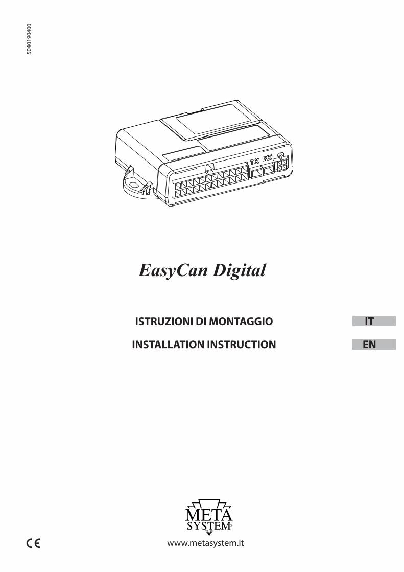
5040190400 www.metasystem.it EasyCan Digital ISTRUZIONI DI MONTAGGIO INSTALLATION INSTRUCTION IT EN
Transcript of 5040190400 Is. Mn. Easycan Digital - gulli-hifi.com · LED lampeggiante Segnale che visualizza lo...
5040
1904
00
www.metasystem.it
EasyCan Digital
ISTRUZIONI DI MONTAGGIO
INSTALLATION INSTRUCTION
IT
EN
2
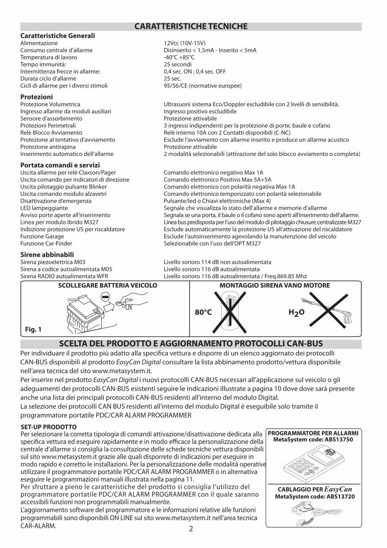
Caratteristiche GeneraliAlimentazione 12Vcc (10V-15V)Consumo centrale d’allarme Disinserito < 1,5mA - Inserito < 5mA Temperatura di lavoro -40°C +85°CTempo immunità: 25 secondiIntermittenza frecce in allarme: 0,4 sec. ON ; 0,4 sec. OFFDurata ciclo d’allarme 25 sec.Cicli di allarme per i diversi stimoli 95/56/CE (normative europee)
ProtezioniProtezione Volumetrica Ultrasuoni sistema Eco/Doppler escludibile con 2 livelli di sensibilità.Ingresso allarme da moduli ausiliari Ingresso positivo escludibile Sensore d’assorbimento Protezione attivabileProtezioni Perimetrali 3 ingressi indipendenti per la protezione di porte, baule e cofanoRelè Blocco Avviamento Relè interno 10A con 2 Contatti disponibili (C-NC)Protezione al tentativo d’avviamento Esclude l’avviamento con allarme inserito e produce un allarme acusticoProtezione antirapina Protezione attivabileInserimento automatico dell’allarme 2 modalità selezionabili (attivazione del solo blocco avviamento o completa)
Portata comandi e serviziUscita allarme per relè Claxson/Pager Comando elettronico negativo Max 1AUscita comando per indicatori di direzione Comando elettronico Positivo Max 5A+5AUscita pilotaggio pulsante Blinker Comando elettronico con polarità negativa Max 1AUscita comando modulo alzavetri Comando elettronico temporizzato con polarità selezionabileDisattivazione d’emergenza Pulsante/led o Chiavi elettroniche (Max 4)LED lampeggiante Segnale che visualizza lo stato dell’allarme e memorie d’allarmeAvviso porte aperte all’inserimento Segnala se una porta, il baule o il cofano sono aperti all’inserimento dell’allarme.Linea per modulo Ibrido M327 Linea bus predisposta per l’uso del modulo di pilotaggio chiusure centralizzate M327Inibizione protezione US per riscaldatore Esclude automaticamente la protezione US all’attivazione del riscaldatoreFunzione Garage Esclude l’autoinserimento agevolando la manutenzione del veicoloFunzione Car-Finder Selezionabile con l’uso dell’OPT M327
Sirene abbinabiliSirena piezoelettrica M03 Livello sonoro 114 dB non autoalimentataSirena a codice autoalimentata M05 Livello sonoro 116 dB autoalimentataSirena RADIO autoalimentata WFR Livello sonoro 116 dB autoalimentata / Freq.869.85 Mhz
MONTAGGIO SIRENA VANO MOTORESCOLLEGARE BATTERIA VEICOLO
80°C H2O
CARATTERISTICHE TECNICHE
SCELTA DEL PRODOTTO E AGGIORNAMENTO PROTOCOLLI CAN-BUSPer individuare il prodotto più adatto alla specifi ca vettura e disporre di un elenco aggiornato dei protocolli CAN-BUS disponibili al prodotto EasyCan Digital consultare la lista abbinamento prodotto/vettura disponibile nell’area tecnica del sito www.metasystem.it. Per inserire nel prodotto EasyCan Digital i nuovi protocolli CAN-BUS necessari all’applicazione sul veicolo o gli adeguamenti dei protocolli CAN-BUS esistenti seguire le indicazioni illustrate a pagina 10 dove dove sarà presente anche una lista dei principali protocolli CAN-BUS residenti all’interno del modulo Digital.La selezione dei protocolli CAN BUS residenti all’interno del modulo Digital è eseguibile solo tramite il programmatore portatile PDC/CAR ALARM PROGRAMMER
SET-UP PRODOTTOPer selezionare la corretta tipologia di comandi attivazione/disattivazione dedicata allaspecifi ca vettura ed eseguire rapidamente e in modo effi cace la personalizzazione della centrale d’allarme si consiglia la consultazione delle schede tecniche vettura disponibilisul sito www.metasystem.it grazie alle quali disporrete di indicazioni per eseguire in modo rapido e corretto le installazioni. Per la personalizzazione delle modalità operative utilizzare il programmatore portatile PDC/CAR ALARM PROGRAMMER o in alternativa eseguire le programmazioni manuali illustrata nella pagina 11.Per sfruttare a pieno le caratteristiche del prodotto si consiglia l’utilizzo del programmatore portatile PDC/CAR ALARM PROGRAMMER con il quale saranno accessibili funzioni non programmabili manualmente.L’aggiornamento software del programmatore e le informazioni relative alle funzioni programmabili sono disponibili ON LINE sul sito www.metasystem.it nell’area tecnica CAR-ALARM.
12
34
56
78
9C
0OK
PROGRAMMATORE PER ALLARMIMetaSystem code: ABS13750
Fig. 1
CABLAGGIO PER EasyCanMetaSystem code: ABS13720
3
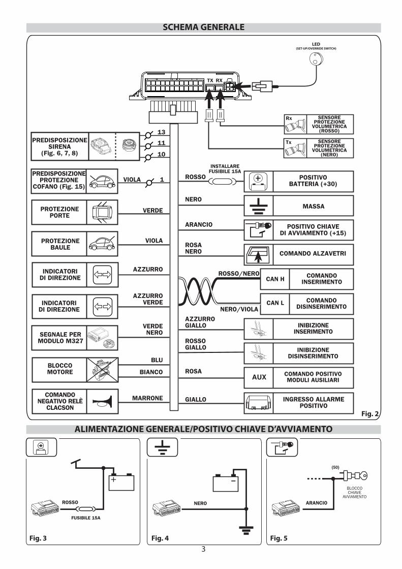
Fig. 2
Fig. 3 Fig. 4 Fig. 5
FUSIBILE 15A
ROSSO NERO
(50)
BLOCCOCHIAVE
AVVIAMENTO
ARANCIO
ALIMENTAZIONE GENERALE/POSITIVO CHIAVE D’AVVIAMENTO
SCHEMA GENERALE
AZZURRO
VIOLA
BIANCO
BLU
AZZURROVERDE
VERDENERO
VERDE
MARRONE
SEGNALE PERMODULO M327
INDICATORIDI DIREZIONE
INDICATORIDI DIREZIONE
BLOCCOMOTORE
COMANDONEGATIVO RELÈ
CLACSON
PROTEZIONEBAULE
PROTEZIONEPORTE
POSITIVOBATTERIA (+30)
MASSA
POSITIVO CHIAVEDI AVVIAMENTO (+15)
COMANDO POSITIVOMODULI AUSILIARI
COMANDO ALZAVETRIROSANERO
ROSA
ARANCIO
NERO
ROSSO
INSTALLAREFUSIBILE 15A
INGRESSO ALLARMEPOSITIVO
GIALLO
PREDISPOSIZIONESIRENA
(Fig. 6, 7, 8)
PREDISPOSIZIONEPROTEZIONE
COFANO (Fig. 15)
INIBIZIONEDISINSERIMENTO
INIBIZIONEINSERIMENTO
AZZURROGIALLO
ROSSOGIALLO
SENSOREPROTEZIONE
VOLUMETRICA(ROSSO)
Rx
Tx
VIOLA 1
COMANDOINSERIMENTO
COMANDODISINSERIMENTO
ROSSO/NERO
NERO/VIOLA
CAN H
CAN L
AUX
SENSOREPROTEZIONE
VOLUMETRICA(NERO)
TX RX
10
11
13
LED(SET-UP/OVERRIDE SWITCH)
4
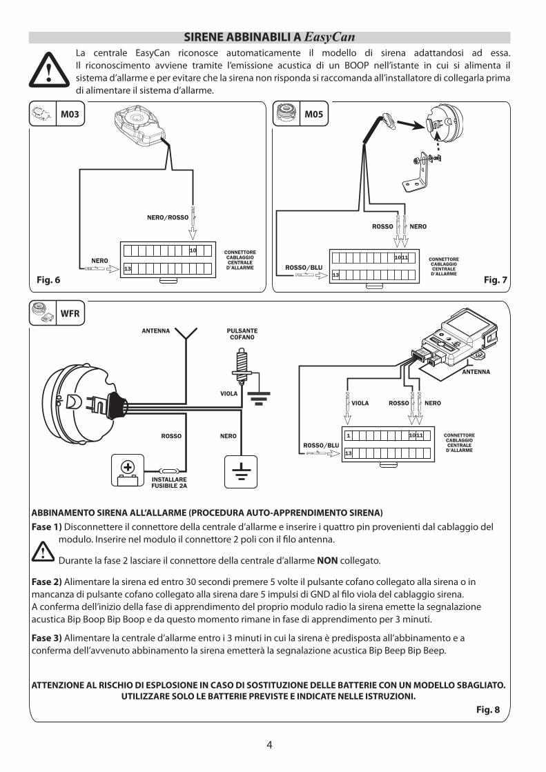
SIRENE ABBINABILI A EasyCan
M03 M05
Fig. 6 Fig. 7
WFR
Fig. 8
La centrale EasyCan riconosce automaticamente il modello di sirena adattandosi ad essa.Il riconoscimento avviene tramite l’emissione acustica di un BOOP nell’istante in cui si alimenta ilsistema d’allarme e per evitare che la sirena non risponda si raccomanda all’installatore di collegarla prima di alimentare il sistema d’allarme.
Fase 1) Disconnettere il connettore della centrale d’allarme e inserire i quattro pin provenienti dal cablaggio del modulo. Inserire nel modulo il connettore 2 poli con il fi lo antenna.
Durante la fase 2 lasciare il connettore della centrale d’allarme NON collegato.
Fase 2) Alimentare la sirena ed entro 30 secondi premere 5 volte il pulsante cofano collegato alla sirena o in mancanza di pulsante cofano collegato alla sirena dare 5 impulsi di GND al fi lo viola del cablaggio sirena.A conferma dell’inizio della fase di apprendimento del proprio modulo radio la sirena emette la segnalazione acustica Bip Boop Bip Boop e da questo momento rimane in fase di apprendimento per 3 minuti.
Fase 3) Alimentare la centrale d’allarme entro i 3 minuti in cui la sirena è predisposta all’abbinamento e a conferma dell’avvenuto abbinamento la sirena emetterà la segnalazione acustica Bip Beep Bip Beep.
ABBINAMENTO SIRENA ALL’ALLARME (PROCEDURA AUTO-APPRENDIMENTO SIRENA)
ATTENZIONE AL RISCHIO DI ESPLOSIONE IN CASO DI SOSTITUZIONE DELLE BATTERIE CON UN MODELLO SBAGLIATO. UTILIZZARE SOLO LE BATTERIE PREVISTE E INDICATE NELLE ISTRUZIONI.
5
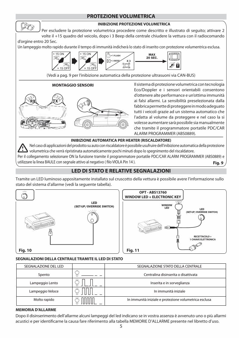
MONTAGGIO SENSORI
RX TX
LED DI STATO E RELATIVE SEGNALAZIONITramite un LED luminoso appositamente installato sul cruscotto della vettura è possibile avere l’informazione sullo stato del sistema d’allarme (vedi la seguente tabella).
SEGNALAZIONE DEL LED SEGNALAZIONE STATO DELLA CENTRALE
Spento Centralina disinserita o disattivata
Lampeggio Lento Inserita e in sorveglianza
Lampeggio Veloce In immunità iniziale
Molto rapido In immunità iniziale e protezione volumetrica esclusa
SEGNALAZIONI DELLA CENTRALE TRAMITE IL LED DI STATO
Dopo il disinserimento dell’allarme alcuni lampeggi del led indicano se in vostra assenza è avvenuto uno o più allarmi acustici e per identifi carne la causa fare riferimento alla tabella MEMORIE D’ALLARME presente nel libretto d’uso.
Il sistema di protezione volumetrica con tecnologia Eco/Doppler e i sensori orientabili consentono d’ottenere alte performance e un’ottima immunità ai falsi allarmi. La sensibilità preselezionata dalla fabbrica permette di proteggere in modo adeguato tutti i veicoli grazie ad un sistema automatico che l’adatta al volume da proteggere e nel caso la si volesse aumentare sarà possibile sia manualmente che tramite il programmatore portatile PDC/CAR ALARM PROGRAMMER (ABS0889).
Per escludere la protezione volumetrica procedere come descritto e illustrato di seguito; attivare 2 volte il +15 quadro del veicolo, dopo i 3 Beep della centrale chiudere la vettura con il radiocomando
d’orgine entro 20 Sec. Un lampeggio molto rapido durante il tempo di immunità indicherà lo stato di inserito con protezione volumentrica esclusa.
INIBIZIONE PROTEZIONE VOLUMETRICA
PROTEZIONE VOLUMETRICA
+ 15 ON
+ 15 OFF
+ 15 ON
+ 15 OFF
MAX20 SEC.
X 3
= 1 FLASH
= 3 BEEP
INIBIZIONE AUTOMATICA PER HEATER (RISCALDATORE)Nel caso di applicazioni del prodotto su auto con riscaldatore è possibile usufruire dell’inibizione automatica della protezione volumetrica che verrà ripristinata automaticamente pochi minuti dopo lo spegnimento del riscaldatore.
Per il collegamento selezionare ON la funzione tramite il programmatore portatile PDC/CAR ALARM PROGRAMMER (ABS0889) e utilizzare la linea BAULE con segnale attivo al negativo ( fi lo VIOLA Pin 14 ).
MEMORIA D’ALLARME
Fig. 9
(Vedi a pag. 9 per l’inibizione automatica della protezione ultrasuoni via CAN-BUS)
Fig. 11Fig. 10
OPT - ABS13760WINDOW LED + ELECTRONIC KEY
RECETTACOLO + 1 CHIAVE ELETTRONICA
LED(SET-UP/OVERRIDE SWITCH) WINDOW
LED LED(SET-UP/OVERRIDE SWITCH)
6
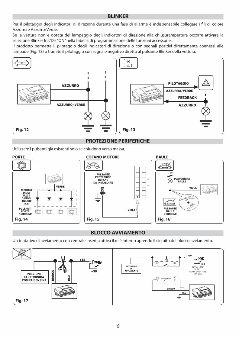
Per il pilotaggio degli indicatori di direzione durante una fase di allarme è indispensabile collegare i fi li di colore Azzurro e Azzurro/Verde.Se la vettura non è dotata del lampeggio degli indicatori di direzione alla chiusura/apertura occorre attivare la selezione Blinker Ins/Dis “ON” nella tabella di programmazione delle funzioni accessorie.Il prodotto permette il pilotaggio degli indicatori di direzione o con segnali positivi direttamente connessi alle lampade (Fig. 13) o tramite il pilotaggio con segnale negativo diretto al pulsante Blinker della vettura.
BLINKER
Fig. 12 Fig. 13
-
AZZURRO
AZZURRO/VERDE AZZURRO
PILOTAGGIO
AZZURRO/VERDE
FEEDBACK
Utilizzare i pulsanti già esistenti solo se chiudono verso massa.
PROTEZIONE PERIFERICHE
VERDEMODULO
DIODIM134
O DIODI1N4002
(X4)
PULSANTIPORTE
D’ORIGINE
PULSANTEPROTEZIONE
COFANODA INSTALLARE
VIOLA
1
+PULSANTE
BAULED’ORIGINE
PLAFONIERABAULE
+ 30
VIOLA
PORTE COFANO MOTORE BAULE
Fig. 14 Fig. 15 Fig. 16
Un tentativo di avviamento con centrale inserita attiva il relè interno aprendo il circuito del blocco avviamento.
BLOCCO AVVIAMENTO
BIA
NC
O
BLU
INIEZIONEELETTRONICA
POMPA BENZINA
+15
+30
+30
BIANCO
MOTORINODI
AVVIAMENTO
+50
INSTALLAREUN REL
SUPPLEMENTARE DA 30A
87 30
86 85
BLU
Fig. 17
7
87 30
86 85
87 30
86 85
+30 o +15
CLACSON+30
COMANDOORIGINALECLACSON
INSTALLARE RELÈSUPPLEMENTARE
SE CLACSONSOTTOCHIAVE
RELÈCLACSOND’ORIGINE
+30
MARRONE
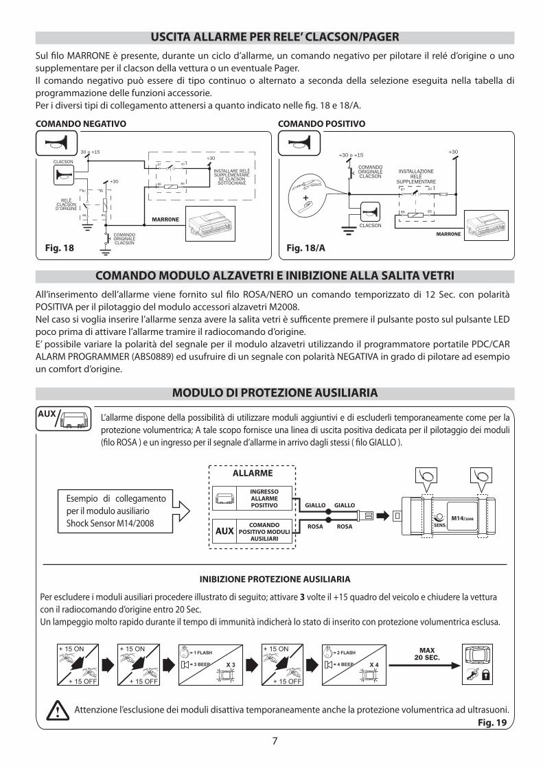
Sul fi lo MARRONE è presente, durante un ciclo d’allarme, un comando negativo per pilotare il relé d’origine o uno supplementare per il clacson della vettura o un eventuale Pager. Il comando negativo può essere di tipo continuo o alternato a seconda della selezione eseguita nella tabella di programmazione delle funzioni accessorie.Per i diversi tipi di collegamento attenersi a quanto indicato nelle fi g. 18 e 18/A.
Fig. 18 Fig. 18/A
USCITA ALLARME PER RELE’ CLACSON/PAGER
COMANDO NEGATIVO COMANDO POSITIVO
All’inserimento dell’allarme viene fornito sul fi lo ROSA/NERO un comando temporizzato di 12 Sec. con polarità POSITIVA per il pilotaggio del modulo accessori alzavetri M2008. Nel caso si voglia inserire l’allarme senza avere la salita vetri è suffi cente premere il pulsante posto sul pulsante LED poco prima di attivare l’allarme tramire il radiocomando d’origine.E’ possibile variare la polarità del segnale per il modulo alzavetri utilizzando il programmatore portatile PDC/CAR ALARM PROGRAMMER (ABS0889) ed usufruire di un segnale con polarità NEGATIVA in grado di pilotare ad esempio un comfort d’origine.
COMANDO MODULO ALZAVETRI E INIBIZIONE ALLA SALITA VETRI
L’allarme dispone della possibilità di utilizzare moduli aggiuntivi e di escluderli temporaneamente come per la protezione volumentrica; A tale scopo fornisce una linea di uscita positiva dedicata per il pilotaggio dei moduli (fi lo ROSA ) e un ingresso per il segnale d’allarme in arrivo dagli stessi ( fi lo GIALLO ).
INIBIZIONE PROTEZIONE AUSILIARIA
Per escludere i moduli ausiliari procedere illustrato di seguito; attivare 3 volte il +15 quadro del veicolo e chiudere la vettura con il radiocomando d’origine entro 20 Sec.Un lampeggio molto rapido durante il tempo di immunità indicherà lo stato di inserito con protezione volumentrica esclusa.
AUX
Attenzione l’esclusione dei moduli disattiva temporaneamente anche la protezione volumentrica ad ultrasuoni.
+ 15 ON
+ 15 OFF
+ 15 ON
+ 15 OFF
MAX20 SEC.
+ 15 ON
+ 15 OFF
X 4
= 2 FLASH
= 4 BEEPX 3
= 1 FLASH
= 3 BEEP
ALLARME
INGRESSOALLARMEPOSITIVO
COMANDOPOSITIVO MODULI
AUSILIARI
GIALLO GIALLO
ROSA ROSA SENS.M14/2008
Esempio di collegamento per il modulo ausiliario Shock Sensor M14/2008
MODULO DI PROTEZIONE AUSILIARIA
Fig. 19
+87 30
86 85
+30 o +15
CLACSON
MARRONE
COMANDOORIGINALECLACSON
INSTALLAZIONERELÈ
SUPPLEMENTARE
+30
8
Fig. 21
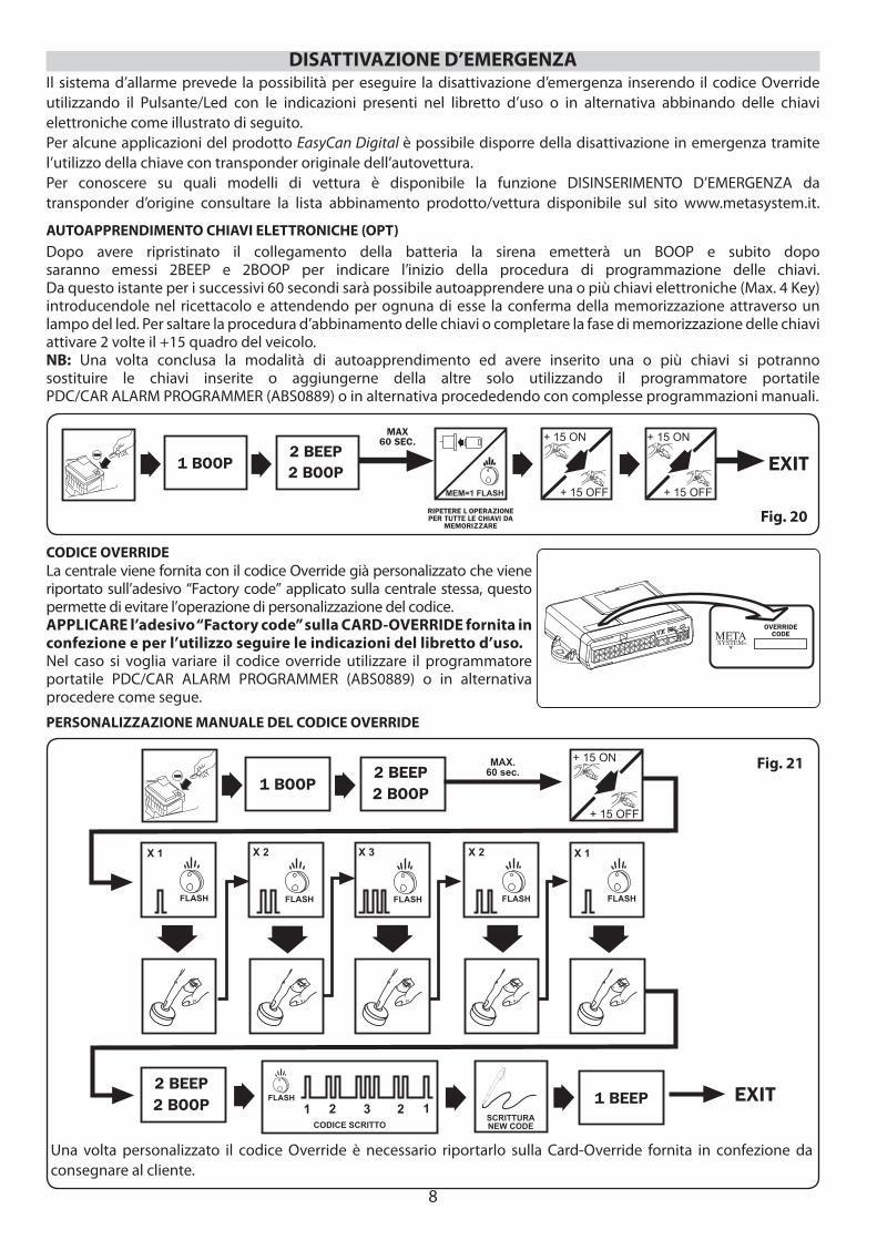
La centrale viene fornita con il codice Override già personalizzato che viene riportato sull’adesivo “Factory code” applicato sulla centrale stessa, questo permette di evitare l’operazione di personalizzazione del codice. APPLICARE l’adesivo “Factory code” sulla CARD-OVERRIDE fornita in confezione e per l’utilizzo seguire le indicazioni del libretto d’uso. Nel caso si voglia variare il codice override utilizzare il programmatore portatile PDC/CAR ALARM PROGRAMMER (ABS0889) o in alternativa procedere come segue.
CODICE OVERRIDE
OVERRIDECODE
Dopo avere ripristinato il collegamento della batteria la sirena emetterà un BOOP e subito dopo saranno emessi 2BEEP e 2BOOP per indicare l’inizio della procedura di programmazione delle chiavi.Da questo istante per i successivi 60 secondi sarà possibile autoapprendere una o più chiavi elettroniche (Max. 4 Key) introducendole nel ricettacolo e attendendo per ognuna di esse la conferma della memorizzazione attraverso un lampo del led. Per saltare la procedura d’abbinamento delle chiavi o completare la fase di memorizzazione delle chiavi attivare 2 volte il +15 quadro del veicolo.NB: Una volta conclusa la modalità di autoapprendimento ed avere inserito una o più chiavi si potranno sostituire le chiavi inserite o aggiungerne della altre solo utilizzando il programmatore portatile PDC/CAR ALARM PROGRAMMER (ABS0889) o in alternativa procededendo con complesse programmazioni manuali.
AUTOAPPRENDIMENTO CHIAVI ELETTRONICHE (OPT)
RIPETERE L OPERAZIONEPER TUTTE LE CHIAVI DA
MEMORIZZARE
MAX60 SEC. + 15 ON
+ 15 OFF
+ 15 ON
+ 15 OFF
2 BEEP2 BOOP EXIT
MEM=1 FLASH
1 BOOP
Fig. 20
DISATTIVAZIONE D’EMERGENZAIl sistema d’allarme prevede la possibilità per eseguire la disattivazione d’emergenza inserendo il codice Override utilizzando il Pulsante/Led con le indicazioni presenti nel libretto d’uso o in alternativa abbinando delle chiavi elettroniche come illustrato di seguito. Per alcune applicazioni del prodotto EasyCan Digital è possibile disporre della disattivazione in emergenza tramite l’utilizzo della chiave con transponder originale dell’autovettura. Per conoscere su quali modelli di vettura è disponibile la funzione DISINSERIMENTO D’EMERGENZA da transponder d’origine consultare la lista abbinamento prodotto/vettura disponibile sul sito www.metasystem.it.
Una volta personalizzato il codice Override è necessario riportarlo sulla Card-Override fornita in confezione da consegnare al cliente.
PERSONALIZZAZIONE MANUALE DEL CODICE OVERRIDE
+ 15 ON
+ 15 OFF
2 BEEP2 BOOP
EXIT
1 BOOP
SCRITTURANEW CODE
2 BEEP2 BOOP
X 1 X 2 X 3 X 2 X 1
FLASH FLASH FLASH FLASH FLASH
MAX.60 sec.
1 BEEPFLASH
CODICE SCRITTO
1 2 3 2 1
9
13
12
24
1
13
12
24
1
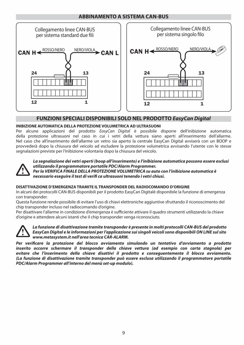
ABBINAMENTO A SISTEMA CAN-BUS
Collegamento linee CAN-BUS per sistema standard due fi li
Collegamento linee CAN-BUS per sistema singolo fi lo
ROSSO/NERO NERO/VIOLA ROSSO/NERO NERO/VIOLA
FUNZIONI SPECIALI DISPONIBILI SOLO NEL PRODOTTO EasyCan Digital INIBIZIONE AUTOMATICA DELLA PROTEZIONE VOLUMETRICA AD ULTRASUONIPer alcune applicazioni del prodotto EasyCan Digital è possibile disporre dell’inibizione automatica della protezione ultrasuoni nel caso in cui i vetri della vettura siano aperti all’inserimento dell’allarme.Nel caso che all’inserimento dell’allarme un vetro sia aperto la centrale EasyCan Digital avviserà con un BOOP e provvederà dopo la chiusura del veicolo ad escludere la protezione volumetrica avvisando l’utente con le stesse segnalazioni previste per l’inibizione volontaria dopo la chiusura del veicolo.
La segnalazione dei vetri aperti (boop all’inserimento) e l’inibizione automatica possono essere esclusi utilizzando il programmatore portatile PDC/Alarm Programmer.Per la VERIFICA FINALE DELLA PROTEZIONE VOLUMETRICA su auto con l’inibizione automatica ènecessario eseguire il test di verifi ca ultrasuoni tenendo i vetri chiusi.
DISATTIVAZIONE D’EMERGENZA TRAMITE IL TRANSPONDER DEL RADIOCOMANDO D’ORIGINEIn alcuni dei protocolli CAN-BUS disponibili per il prodotto EasyCan Digitalè disponibile la funzione di emergenza con transponder.Questa funzione rende possibile di evitare l’uso di chiavi elettroniche aggiuntive sfruttando il riconoscimento del chip transponder incluso nel radiocomando d’origine.Per disattivare l’allarme in condizione d’emergenza è suffi ciente attivare il quadro strumenti utilizzando la chiave d’origine e attendere alcuni istanti che il chip transponder venga riconosciuto.
La funzione di disattivazione tramite transponder è presente in molti protocolli CAN-BUS del prodottoEasyCan Digital e le informazioni per l’applicazione sui singoli veicoli sono disponibili ON LINE sul sito www.metasystem.it nell’area tecnica CAR-ALARM.
Per verifi care la protezione del blocco avviamento simulando un tentativo d’avviamento a prodottoinserito occorre schermare il transponder della chiave vettura (ad esempio con carta stagnola) per evitare che l’inserimento della chiave disattivi il prodotto e conseguentemente il blocco avviamento.(La funzione di disattivazione tramite transponder può essere esclusa utilizzando il programmatore portatile PDC/Alarm Programmer all’interno del menù set-up modulo).
10
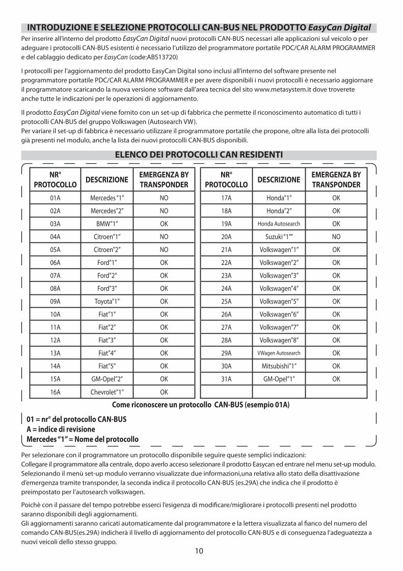
Per inserire all’interno del prodotto EasyCan Digital nuovi protocolli CAN-BUS necessari alle applicazioni sul veicolo o per adeguare i protocolli CAN-BUS esistenti è necessario l’utilizzo del programmatore portatile PDC/CAR ALARM PROGRAMMER e del cablaggio dedicato per EasyCan (code:ABS13720)
I protocolli per l’aggiornamento del prodotto EasyCan Digital sono inclusi all’interno del software presente nelprogrammatore portatile PDC/CAR ALARM PROGRAMMER e per avere disponibili i nuovi protocolli è necessario aggiornareil programmatore scaricando la nuova versione software dall’area tecnica del sito www.metasystem.it dove trovereteanche tutte le indicazioni per le operazioni di aggiornamento.
Il prodotto EasyCan Digital viene fornito con un set-up di fabbrica che permette il riconoscimento automatico di tutti i protocolli CAN-BUS del gruppo Volkswagen (Autosearch VW).Per variare il set-up di fabbrica è necessario utilizzare il programmatore portatile che propone, oltre alla lista dei protocolli già presenti nel modulo, anche la lista dei nuovi protocolli CAN-BUS disponibili.
INTRODUZIONE E SELEZIONE PROTOCOLLI CAN-BUS NEL PRODOTTO EasyCan Digital
NR° PROTOCOLLO DESCRIZIONE EMERGENZA BY
TRANSPONDERNR°
PROTOCOLLO DESCRIZIONE EMERGENZA BY TRANSPONDER
01A Mercedes “1” NO 17A Honda”1” OK
02A Mercedes”2” NO 18A Honda”2” OK
03A BMW”1” OK 19A Honda Autosearch OK
04A Citroen”1” NO 20A Suzuki “1”” NO
05A Citroen”2” NO 21A Volkswagen”1” OK
06A Ford”1” OK 22A Volkswagen”2” OK
07A Ford”2” OK 23A Volkswagen”3” OK
08A Ford”3” OK 24A Volkswagen”4” OK
09A Toyota”1” OK 25A Volkswagen”5” OK
10A Fiat”1” OK 26A Volkswagen”6” OK
11A Fiat”2” OK 27A Volkswagen”7” OK
12A Fiat”3” OK 28A Volkswagen”8” OK
13A Fiat”4” OK 29A VWagen Autosearch OK
14A Fiat”5” OK 30A Mitsubishi”1” OK
15A GM-Opel”2” OK 31A GM-Opel”1” OK
16A Chevrolet”1” OK
Per selezionare con il programmatore un protocollo disponibile seguire queste semplici indicazioni:Collegare il programmatore alla centrale, dopo averlo acceso selezionare il prodotto Easycan ed entrare nel menu set-up modulo.Selezionando il menù set-up modulo verranno visualizzate due informazioni,una relativa allo stato della disattivazione d’emergenza tramite transponder, la seconda indica il protocollo CAN-BUS (es.29A) che indica che il prodotto è preimpostato per l’autosearch volkswagen.
Poichè con il passare del tempo potrebbe esserci l’esigenza di modifi care/migliorare i protocolli presenti nel prodotto saranno disponibili degli aggiornamenti.Gli aggiornamenti saranno caricati automaticamente dal programmatore e la lettera visualizzata al fi anco del numero del comando CAN-BUS(es.29A) indicherà il livello di aggiornamento del protocollo CAN-BUS e di conseguenza l’adeguatezza a nuovi veicoli dello stesso gruppo.
ELENCO DEI PROTOCOLLI CAN RESIDENTI
Come riconoscere un protocollo CAN-BUS (esempio 01A)
01 = nr° del protocollo CAN-BUSA = indice di revisioneMercedes “1” = Nome del protocollo
11
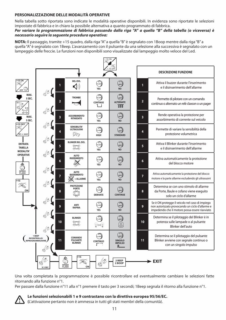
Una volta completata la programmazione è possibile ricontrollare ed eventualmente cambiare le selezioni fatte ritornando alla funzione n°1. Per passare dalla funzione n°11 alla n°1 premere il tasto per 3 secondi; 1Beep segnala il ritorno alla funzione n°1.
DESCRIZIONE FUNZIONE
1INS./DIS.
FLASH
YES
OFF
NO1
Attiva il buzzer durante l’inserimentoe il disinserimento dell’allarme
2TROMBE
FLASH
CONTINUE
OFF
ALTERNATE 2Permette di pilotare con un comando
continuo o alternato un relè claxson o un pager
3 ASSORBIMENTORITARDATO
FLASH
YES
OFF
NO3
Rende operativa la protezione per assorbimento di corrente sul veicolo
4SENSIBILITA’ULTRASUONI
FLASH
HIGH
OFF
STANDARD4
Permette di variare la sensibilità della protezione volumetrica
5BLINKER INS./DIS.
FLASH
YES
OFF
NO5
Attiva il Blinker durante l’inserimentoe il disinserimento dell’allarme
6AUTO
INSERIMENTO
FLASH
YES
OFF
NO6
Attiva automaticamente la protezionedel blocco motore
7AUTO
INSERIMENTO
+ ALLARME
FLASH
YES
OFF
NO7
Attiva automaticamente la protezione del bloccomotore e la parte allarme escludendo gli ultrasuoni
8PROTEZIONE
PORTE
FLASH
DERIVATE
OFF
CONTINUE8
Determina se con uno stimolo di allarme da Porte, Baule e cofano viene eseguito
solo un ciclo d’allarme
9 ANTIRAPINA
FLASH
YES
OFF
NO9
Se è ON protegge il veicolo nel caso di impiego non autorizzato provocando un ciclo d’allarme e impedendo che il motore possa essere riavviato
10BLINKER
FLASH
OFF
10Determina se il pilotaggio del Blinker è in
potenza sulle lampade o al pulsante Blinker dell’auto
11COMANDO PULSANTE
BLINKER
FLASH
CONTINUO
OFF
SINGOLO IMPULSO
11Determina se il pilotaggio del pulsante Blinker avviene con segnale continuo o
con un singolo impulso
+15
ON
X 4
X 4
MAX.5 SEC.
MAX.5 SEC.
ENTRATA TABELLA
MODALITA’OPERATIVE
= 4 BEEP
+15 OFF
SPEEDFLASH
+ 15 ON
+ 15 OFF
SPEEDFLASH
+15
ON
EXIT
OFF
+15 ON
1 BEEPRICONTROLLO/
RIPROGRAMMAZIONE
PERSONALIZZAZIONE DELLE MODALITÀ OPERATIVENella tabella sotto riportata sono indicate le modalità operative disponibili. In evidenza sono riportate le selezioni impostate di fabbrica e in chiaro la possibile alternativa a quanto programmato di fabbrica. Per variare la programmazione di fabbrica passando dalla riga “A” a quella “B” della tabella (o viceversa) è necessario seguire la seguente procedura operativa:
NOTA: Il passaggio, tramite +15 quadro, dalla riga “A” a quella “B” è segnalato con 1Boop mentre dalla riga “B” a quella “A” è segnalato con 1Beep. L’avanzamento con il pulsante da una selezione alla successiva è segnalato con un lampeggio delle freccie. Le funzioni non disponibili sono visualizzate dal lampeggio molto veloce del Led.
2 BEEP2 BOOP
Le funzioni selezionabili 1 e 9 contrastano con la direttiva europea 95/56/EC. (L’attivazione pertanto non è ammessa in tutti gli stati membri della comunità).
X 3 SEC.
12
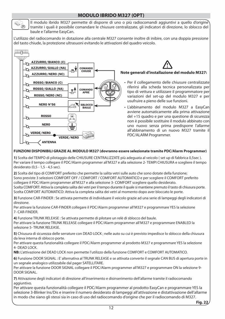
MODULO IBRIDO M327 (OPT)Il modulo ibrido M327 permette di disporre di uno o più radiocomandi aggiuntivi a quello d’origine tramite i quali è possibile comandare le chiusure centralizzate, gli indicatori di direzione, lo sblocco del baule e l’allarme EasyCan.
L’utilizzo del radiocomando in dotazione alla centrale M327 consente inoltre di inibire, con una doppia pressione del tasto chiude, la protezione ultrasuoni evitando le attivazioni del quadro veicolo.
Fig. 22
Note generali d’installazione del modulo M327:
Per il collegamento delle chiusure centralizzate riferirsi alla scheda tecnica personalizzata per tipo di vettura e utilizzare il programmatore per variazioni del set-up del modulo M327 e per usufruire a pieno delle sue funzioni.L’abbinamento del modulo M327 a EasyCan avviene automaticamente alla prima attivazione del +15 quadro e per una questione di sicurezza non è possibile sostituire il modulo abbinato con uno nuovo senza prima predisporre l’allarme all’abbinamento di un nuovo M327 tramite il PDC/ALARM Programmer.
•
•
FUNZIONI DISPONIBILI GRAZIE AL MODULO M327 (dovranno essere selezionate tramite PDC/Alarm Programmer)
1) Scelta del TEMPO di pilotaggio delle CHIUSURE CENTRALIZZATE più adeguata al veicolo ( set up di fabbrica 0,5sec ). Per variare il tempo collegare il PDC/Alarm programmer all’M327 e alla selezione 2- TEMPI CHIUSURA e scegliere il tempo desiderato (0,5 - 1,5 - 4,5 sec).
2) Scelta del tipo di COMFORT preferito che permette la salita vetri sulle auto che sono dotate della funzione; Sono previste 3 selezioni COMFORT OFF / COMFORT / COMFORT AUTOMATICO e per scegliere il COMFORT preferito collegare il PDC/Alarm programmer all’M327 e alla selezione 3- COMFORT scegliere quello desiderato.Scelta COMFORT: Attiva la completa salita dei vetri per il tempo durante il quale si mantiene premuto il tasto di chiusura porte.Scelta COMFORT AUTOMATICO: Attiva la completa salita dei vetri al momento dopo aver bloccato le porte.
3) Funzione CAR-FINDER : Se attivata permette di individuare il veicolo grazie ad una serie di lampeggi degli indicatori di direzione.Per attivare la funzione CAR-FINDER collegare il PDC/Alarm programmer all’M327 e programmare YES la selezione 7- CAR-FINDER.
4) Funzione TRUNK RELEASE : Se attivata permette di pilotare un relè di sblocco del baule.Per attivare la funzione TRUNK RELEASE collegare il PDC/Alarm programmer all’M327 e programmare ENABLED la selezione 5- TRUNK RELEASE.
5) Chiusura di sicurezza delle serrature con DEAD LOCK ; nelle auto su cui è previsto impedisce lo sblocco della chiusura da leva interna di sblocco porte.Per attivare questa funzionalità collegare il PDC/Alarm programmer al prodotto M327 e programmare YES la selezione 4- DEAD LOCK. NB: L’attivazione del DEAD LOCK non permette l’utilizzo della funzione COMFORT e COMFORT AUTOMATICO.
6) Funzione DOOR SIGNAL : E’ alternativa al TRUNK RELEASE e se attivata converte il segnale CAN BUS di apertura porte in un segnale analogico utilizzabile dal pager SATELLITARE.Per attivare la funzione DOOR SIGNAL collegare il PDC/Alarm programmer all’M327 e programmare ON la selezione 9- DOOR SIGNAL.
7) Attivazione degli indicatori di direzione all’inserimento e disinserimento dell’allarme tramite il radiocomando aggiuntivo.Per attivare questa funzionalità collegare il PDC/Alarm programmer al prodotto EasyCan e programmare YES la selezione 3-Blinker Ins/Dis e inserire il numero desiderato di lampeggi all’attivazione e distattivazione dell’allarme in modo che siano gli stessi sia in caso di uso del radiocomando d’origine che per il radiocomando di M327.
13
Al termine dell’installazione la centrale d’allarme si trova nella condizione di disinserita e occorre eseguire le seguenti operazioni:chiudere le porte; il cofano; il baule ed i vetri, avendo cura di non lasciare i radiocomandi d’origine all’interno del veicolo.1. Eff ettuare un avviamento del veicolo per verifi care la corretta funzionalità dei collegamenti relativi al blocco avviamento;2. Bloccare la serratura delle porte tramite il radiocomando di origine (inserimento del sistema di allarme) e verificare che avvengano i lampeggi degli indicatori di direzione di origine della vettura.3. Il LED lampeggia velocemente durante l’immunità iniziale di 25 sec. durante la quale eseguire i seguenti test che se positivi devono generare un lampeggio delle frecce e 1 beep della sirena: • aprire e richiudere in sequenza una porta, il cofano ed il baule; • ruotare la chiave di avviamento in posizione ON (Vedi pag.9 disinserimento d’emergenza da transponder d’origine) • muovere una mano avanti e indietro rispetto ai sensori ultrasonici installati; • stimolare i moduli aggiuntivi di protezione (es. Shock sensor).Ad ogni lampeggio delle frecce il tempo dell’immunità iniziale riparte da zero.4. Terminata l’immunità iniziale, il LED lampeggia più lentamente e l’attivazione di una protezione dall’allarme genera un ciclo d’allarme di 25 sec. durante i quali la sirena emette un caratteristico suono modulato, gli indicatori di direzione lampeggiano ed il clacson, se collegato, suona continuo o alternato a seconda della programmazione.Durante il ciclo d’allarme verifi care la corretta funzionalità della protezione sul blocco avviamento;5. Sbloccare la serratura delle porte tramite il radiocomando di origine e verifi care il disinserimento del sistema di allarme; al disinserimento la sirena emetterà un avviso acustico BOOP e il LED lampeggerà con le sequenze previste per segnalare le memorie d’allarme (vedi libretto d’uso).
VERIFICHE AGGIUNTIVE IN CASO DI ABBINAMENTO DEL MODULO IBRIDO M327
Per verifi care la corretta funzionalità del modulo M327 procedere come segue:1. Bloccare le serrature premendo il tasto chiude del radiocomando e verifi care: • Che gli indicatori di direzione abbiano eseguito il numero di lampeggi relativi alla chiusura, che le serrature si siano bloccate e che l’allarme si sia inserito (led lampeggia velocemente). • Premere nuovamente il tasto chiude entro il tempo d’immunità (25 sec.) e verifi care che vengano inibiti gli ultrasuoni (la sirena emetta 3 beep per indicare l’esclusione degli ultrasuoni).
2. Sbloccare la serratura del baule premendo il tasto baule del radiocomando e verifi care che la serratura si sia sbloccata e che gli ultrasuoni siano stati inibiti.
3. Sbloccare le serrature premendo il tasto apre del radiocomando e verifi care che gli indicatori di direzione abbiano eseguito il numero di lampeggi relativi alla apertura, che le serrature si siano sbloccate e che l’allarme si sia disinserito (led spento).
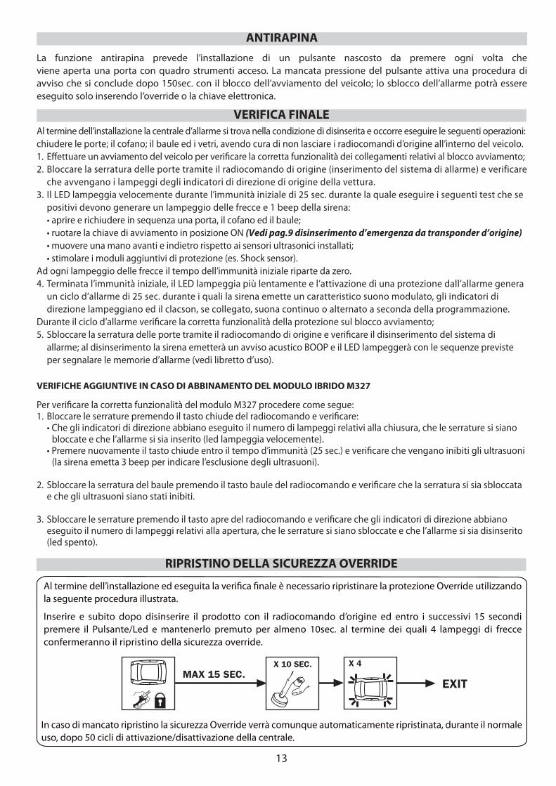
Al termine dell’installazione ed eseguita la verifi ca fi nale è necessario ripristinare la protezione Override utilizzando la seguente procedura illustrata.
Inserire e subito dopo disinserire il prodotto con il radiocomando d’origine ed entro i successivi 15 secondi premere il Pulsante/Led e mantenerlo premuto per almeno 10sec. al termine dei quali 4 lampeggi di frecce confermeranno il ripristino della sicurezza override.
VERIFICA FINALE
RIPRISTINO DELLA SICUREZZA OVERRIDE
MAX 15 SEC.X 10 SEC. X 4
EXIT
ANTIRAPINALa funzione antirapina prevede l’installazione di un pulsante nascosto da premere ogni volta cheviene aperta una porta con quadro strumenti acceso. La mancata pressione del pulsante attiva una procedura di avviso che si conclude dopo 150sec. con il blocco dell’avviamento del veicolo; lo sblocco dell’allarme potrà essere eseguito solo inserendo l’override o la chiave elettronica.
In caso di mancato ripristino la sicurezza Override verrà comunque automaticamente ripristinata, durante il normale uso, dopo 50 cicli di attivazione/disattivazione della centrale.
14
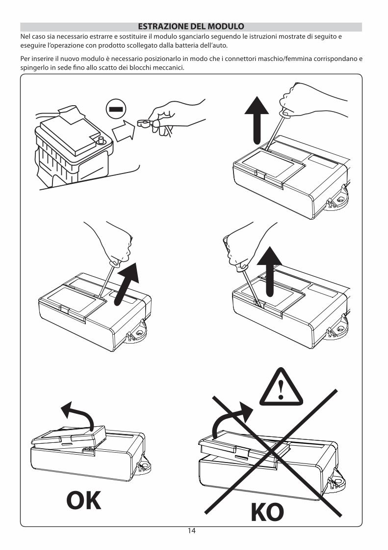
ESTRAZIONE DEL MODULO
KO
Nel caso sia necessario estrarre e sostituire il modulo sganciarlo seguendo le istruzioni mostrate di seguito e eseguire l’operazione con prodotto scollegato dalla batteria dell’auto.
Per inserire il nuovo modulo è necessario posizionarlo in modo che i connettori maschio/femmina corrispondano e spingerlo in sede fi no allo scatto dei blocchi meccanici.
OK
15
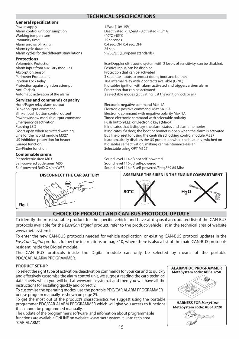
General specificationsPower supply 12Vdc (10V-15V)Alarm control unit consumption Deactivated < 1,5mA - Activated < 5mA Working temperature -40°C +85°CImmunity time: 25 secondsAlarm arrows blinking: 0.4 sec. ON; 0.4 sec. OFFAlarm cycle duration 25 sec.Alarm cycles for the different stimulations 95/56/EC (European standards)
ProtectionsVolumetric Protection Eco/Doppler ultrasound system with 2 levels of sensitivity, can be disabled.Alarm input from auxiliary modules Positive input, can be disabled Absorption sensor Protection that can be activated Perimeter Protections 3 separate inputs to protect doors, boot and bonnetIgnition Lock Relay 10A internal relay with 2 contacts available (C-NC)Protection against ignition attempt It disables ignition with alarm activated and triggers a siren alarmAnti-Carjack Protection that can be activated Automatic activation of the alarm 2 selectable modes (activating just the ignition lock or all)
Services and commands capacityHorn/Pager relay alarm output Electronic negative command Max 1ABlinker output command Electronic positive command Max 5A+5ABlinker push button control output Electronic command with negative polarity Max 1APower window module output command Timed electronic command with selectable polarityEmergency deactivation Push button/LED or Electronic keys (Max 4)Flashing LED It indicates that it displays the alarm status and alarm memoriesDoors open when activated warning It indicates if a door, the boot or bonnet is open when the alarm is activated.Line for the hybrid module M327 Bus line preset for using the centralised locking control module M327US inhibition protection for heater It automatically disables the US protection when the heater is switched onGarage function It disables self-activation, making car maintenance easierCar-Finder function Selectable using OPT M327
Combinable sirensPiezoelectric siren M03 Sound level 114 dB not self-poweredSelf-powered code siren M05 Sound level 116 dB self-poweredSelf-powered RADIO siren WFR Sound level 116 dB self-powered/Freq.869.85 Mhz
ASSEMBLE THE SIREN IN THE ENGINE COMPARTMENTDISCONNECT THE CAR BATTERY
TECHNICAL SPECIFICATIONS
PRODUCT SET-UPTo select the right type of activation/deactivation commands for your car and to quickly and eff ectively customise the alarm control unit, we suggest reading the car’s technical data sheets which you will fi nd at www.metasystem.it and then you will have all the instructions for installing quickly and correctly.To customise the operating modes, use the portable PDC/CAR ALARM PROGRAMMER or else program manually as shown on page 25.To get the most out of the product’s characteristics we suggest using the portable programmer PDC/CAR ALARM PROGRAMMER which will give you access to functions that cannot be programmed manually.The update of the programmer’s software, and infomation about programmable functions are available ONLINE on website www.metasystem.it , into tech area “CAR-ALARM”.
Fig. 1
12
34
56
78
9C
0OK
ALARM/PDC PROGRAMMERMetaSystem code: ABS13750
HARNESS FOR EasyCanMetaSystem code: ABS13720
80°C H2O
CHOICE OF PRODUCT AND CAN-BUS PROTOCOL UPDATETo identify the most suitable product for the specifi c vehicle and have at disposal an updated list of the CAN-BUS protocols available for the EasyCan Digital product, refer to the product/vehicle list in the technical area of website www.metasystem.it. To enter the new CAN-BUS protocols needed for vehicle application, or existing CAN-BUS protocol updates in the EasyCan Digital product, follow the instructions on page 10, where there is also a list of the main CAN-BUS protocols resident inside the Digital module.The CAN BUS protocols inside the Digital module can only be selected by means of the portable PDC/CAR ALARM PROGRAMMER.
16
Fig. 2
Fig. 3 Fig. 4 Fig. 5
FUSIBILE 15A
ROSSO NERO
(50)
BLOCCOCHIAVE
AVVIAMENTO
ARANCIO
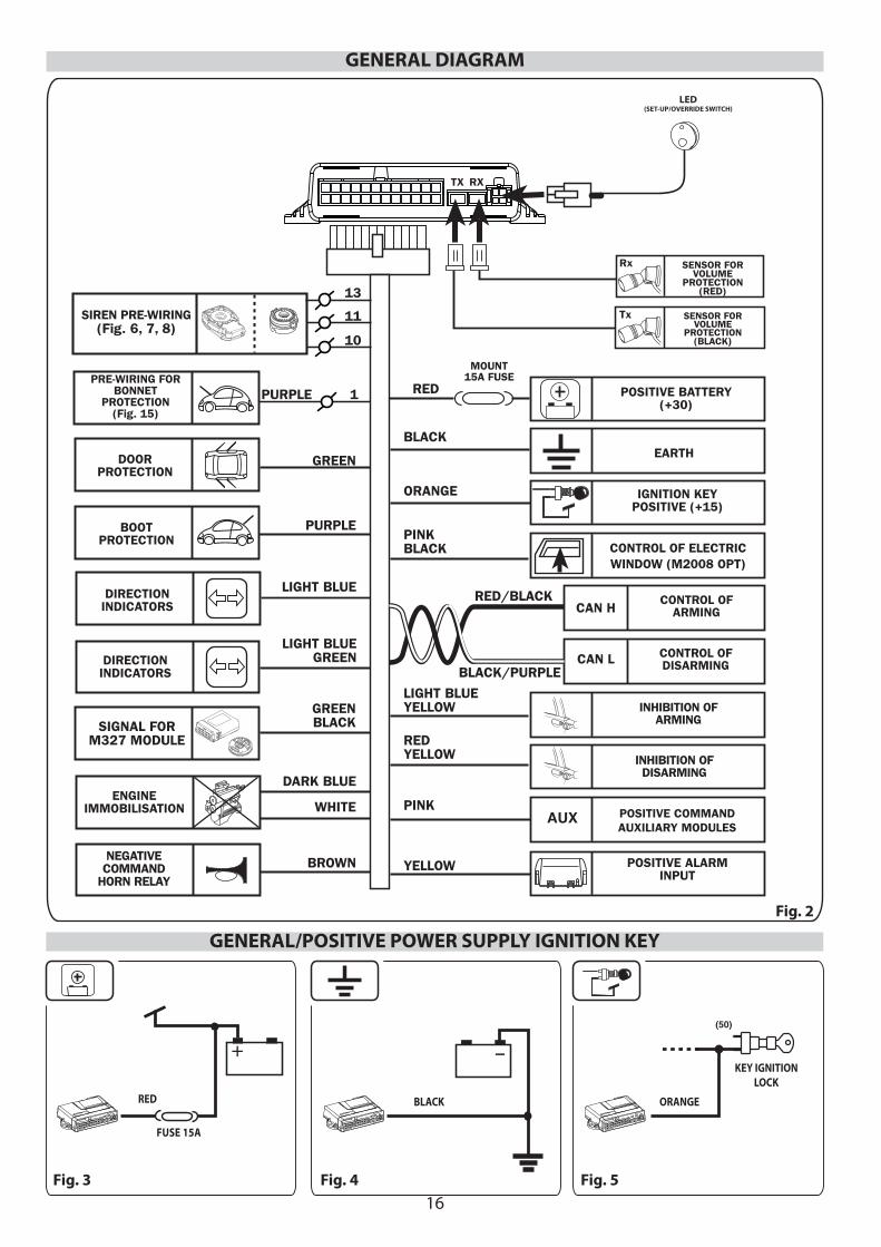
GENERAL/POSITIVE POWER SUPPLY IGNITION KEY
GENERAL DIAGRAM
LIGHT BLUE
PURPLE
WHITE
DARK BLUE
LIGHT BLUEGREEN
GREENBLACK
GREEN
BROWN
SIGNAL FORM327 MODULE
PINKBLACK
PINK
ORANGE
BLACK
RED
MOUNT15A FUSE
YELLOW
LIGHT BLUEYELLOW
REDYELLOW
Rx
Tx
PURPLE 1
SIREN PRE-WIRING(Fig. 6, 7, 8)
PRE-WIRING FORBONNET
PROTECTION(Fig. 15)
BOOTPROTECTION
DOORPROTECTION
DIRECTIONINDICATORS
DIRECTIONINDICATORS
ENGINEIMMOBILISATION
NEGATIVECOMMAND
HORN RELAY
POSITIVE BATTERY(+30)
EARTH
IGNITION KEYPOSITIVE (+15)
CONTROL OF ELECTRICWINDOW (M2008 OPT)
POSITIVE COMMANDAUXILIARY MODULES
POSITIVE ALARMINPUT
CONTROL OFARMING
CONTROL OFDISARMING
RED/BLACK
BLACK/PURPLE
CAN H
CAN L
AUX
TX RX
SENSOR FORVOLUME
PROTECTION(RED)
SENSOR FORVOLUME
PROTECTION(BLACK)
INHIBITION OFDISARMING
INHIBITION OFARMING
10
11
13
RED
FUSE 15A
BLACK ORANGE
KEY IGNITION LOCK
LED(SET-UP/OVERRIDE SWITCH)
17
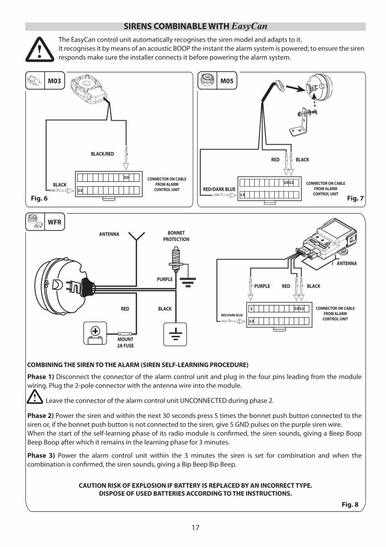
SIRENS COMBINABLE WITH EasyCan
M03 M05
Fig. 6 Fig. 7
WFR
Fig. 8
The EasyCan control unit automatically recognises the siren model and adapts to it.It recognises it by means of an acoustic BOOP the instant the alarm system is powered; to ensure the siren responds make sure the installer connects it before powering the alarm system.
Phase 1) Disconnect the connector of the alarm control unit and plug in the four pins leading from the module wiring. Plug the 2-pole connector with the antenna wire into the module.
Leave the connector of the alarm control unit UNCONNECTED during phase 2.
Phase 2) Power the siren and within the next 30 seconds press 5 times the bonnet push button connected to the siren or, if the bonnet push button is not connected to the siren, give 5 GND pulses on the purple siren wire.When the start of the self-learning phase of its radio module is confi rmed, the siren sounds, giving a Beep Boop Beep Boop after which it remains in the learning phase for 3 minutes.
Phase 3) Power the alarm control unit within the 3 minutes the siren is set for combination and when the combination is confi rmed, the siren sounds, giving a Bip Beep Bip Beep.
COMBINING THE SIREN TO THE ALARM (SIREN SELF-LEARNING PROCEDURE)
BLACK/RED
RED/DARK BLUEBLACK
RED BLACK
CONNECTOR ON CABLEFROM ALARM
CONTROL UNITCONNECTOR ON CABLE
FROM ALARMCONTROL UNIT
BONNET PROTECTION
ANTENNA
RED BLACK
ANTENNA
CONNECTOR ON CABLEFROM ALARM
CONTROL UNITRED/DARK BLUE
PURPLEPURPLE RED BLACK
MOUNT 2A FUSE
CAUTION RISK OF EXPLOSION IF BATTERY IS REPLACED BY AN INCORRECT TYPE.DISPOSE OF USED BATTERIES ACCORDING TO THE INSTRUCTIONS.
18
ASSEMBLING THE SENSORS
RX TX
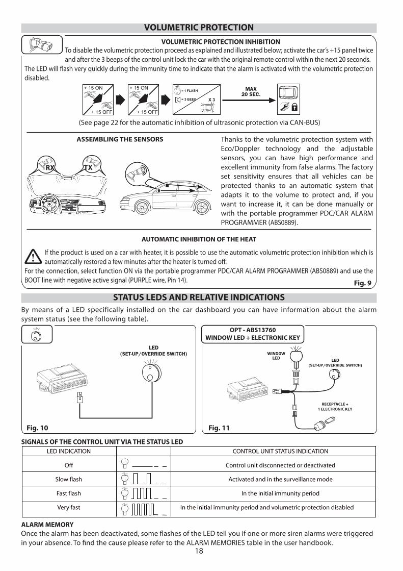
STATUS LEDS AND RELATIVE INDICATIONSBy means of a LED specifically installed on the car dashboard you can have information about the alarm system status (see the following table).
LED INDICATION CONTROL UNIT STATUS INDICATION
Off Control unit disconnected or deactivated
Slow fl ash Activated and in the surveillance mode
Fast fl ash In the initial immunity period
Very fast In the initial immunity period and volumetric protection disabled
SIGNALS OF THE CONTROL UNIT VIA THE STATUS LED
Once the alarm has been deactivated, some fl ashes of the LED tell you if one or more siren alarms were triggered in your absence. To fi nd the cause please refer to the ALARM MEMORIES table in the user handbook.
Thanks to the volumetric protection system with Eco/Doppler technology and the adjustable sensors, you can have high performance and excellent immunity from false alarms. The factory set sensitivity ensures that all vehicles can be protected thanks to an automatic system that adapts it to the volume to protect and, if you want to increase it, it can be done manually or with the portable programmer PDC/CAR ALARM PROGRAMMER (ABS0889).
To disable the volumetric protection proceed as explained and illustrated below; activate the car’s +15 panel twice and after the 3 beeps of the control unit lock the car with the original remote control within the next 20 seconds.
The LED will fl ash very quickly during the immunity time to indicate that the alarm is activated with the volumetric protection disabled.
VOLUMETRIC PROTECTION INHIBITION
VOLUMETRIC PROTECTION
+ 15 ON
+ 15 OFF
+ 15 ON
+ 15 OFF
MAX20 SEC.
X 3
= 1 FLASH
= 3 BEEP
AUTOMATIC INHIBITION OF THE HEAT
If the product is used on a car with heater, it is possible to use the automatic volumetric protection inhibition which is automatically restored a few minutes after the heater is turned off .
For the connection, select function ON via the portable programmer PDC/CAR ALARM PROGRAMMER (ABS0889) and use the BOOT line with negative active signal (PURPLE wire, Pin 14).
ALARM MEMORY
Fig. 9
Fig. 11Fig. 10
OPT - ABS13760WINDOW LED + ELECTRONIC KEY
LED(SET-UP/OVERRIDE SWITCH) WINDOW
LED LED(SET-UP/OVERRIDE SWITCH)
RECEPTACLE + 1 ELECTRONIC KEY
(See page 22 for the automatic inhibition of ultrasonic protection via CAN-BUS)
19
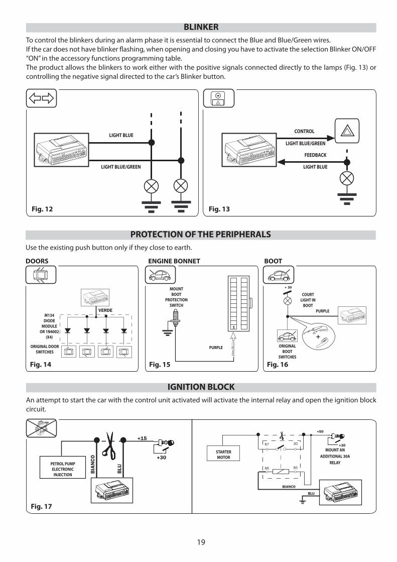
To control the blinkers during an alarm phase it is essential to connect the Blue and Blue/Green wires.If the car does not have blinker fl ashing, when opening and closing you have to activate the selection Blinker ON/OFF “ON” in the accessory functions programming table.The product allows the blinkers to work either with the positive signals connected directly to the lamps (Fig. 13) or controlling the negative signal directed to the car’s Blinker button.
BLINKER
Fig. 12 Fig. 13
-
AZZURRO
AZZURRO/VERDE AZZURRO
PILOTAGGIO
AZZURRO/VERDE
FEEDBACK
Use the existing push button only if they close to earth.
PROTECTION OF THE PERIPHERALS
VERDEMODULO
DIODIM134
O DIODI1N4002
(X4)
PULSANTIPORTE
D’ORIGINE
PULSANTEPROTEZIONE
COFANODA INSTALLARE
VIOLA
1
+PULSANTE
BAULED’ORIGINE
PLAFONIERABAULE
+ 30
VIOLA
DOORS ENGINE BONNET BOOT
Fig. 14 Fig. 15 Fig. 16
An attempt to start the car with the control unit activated will activate the internal relay and open the ignition block circuit.
IGNITION BLOCK
BIA
NC
O
BLU
INIEZIONEELETTRONICA
POMPA BENZINA
+15
+30
+30
BIANCO
MOTORINODI
AVVIAMENTO
+50
INSTALLAREUN REL
SUPPLEMENTARE DA 30A
87 30
86 85
BLU
Fig. 17
LIGHT BLUE
LIGHT BLUE/GREEN
LIGHT BLUE/GREEN
LIGHT BLUE
CONTROL
FEEDBACK
M134 DIODE
MODULE OR 1N4002
(X4)
ORIGINAL DOOR SWITCHES
MOUNT BOOT
PROTECTION SWITCH
PURPLE
PURPLE
COURTLIGHT IN
BOOT
ORIGINAL BOOT
SWITCHES
PETROL PUMP ELECTRONIC
INJECTION
STARTER MOTOR
MOUNT AN ADDITIONAL 30A
RELAY
20
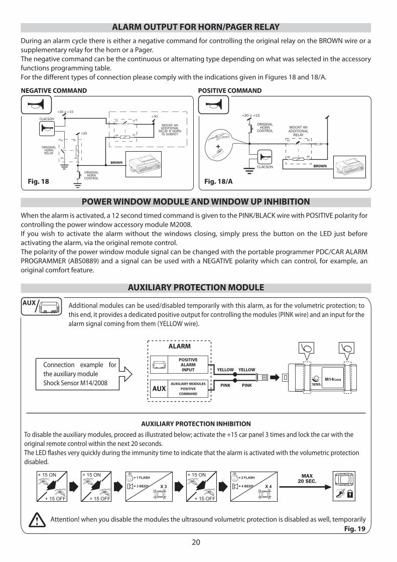
During an alarm cycle there is either a negative command for controlling the original relay on the BROWN wire or a supplementary relay for the horn or a Pager. The negative command can be the continuous or alternating type depending on what was selected in the accessory functions programming table.For the diff erent types of connection please comply with the indications given in Figures 18 and 18/A.
Fig. 18 Fig. 18/A
ALARM OUTPUT FOR HORN/PAGER RELAY
NEGATIVE COMMAND POSITIVE COMMAND
When the alarm is activated, a 12 second timed command is given to the PINK/BLACK wire with POSITIVE polarity for controlling the power window accessory module M2008. If you wish to activate the alarm without the windows closing, simply press the button on the LED just before activating the alarm, via the original remote control.The polarity of the power window module signal can be changed with the portable programmer PDC/CAR ALARM PROGRAMMER (ABS0889) and a signal can be used with a NEGATIVE polarity which can control, for example, an original comfort feature.
POWER WINDOW MODULE AND WINDOW UP INHIBITION
Additional modules can be used/disabled temporarily with this alarm, as for the volumetric protection; to this end, it provides a dedicated positive output for controlling the modules (PINK wire) and an input for the alarm signal coming from them (YELLOW wire).
AUXILIARY PROTECTION INHIBITION
To disable the auxiliary modules, proceed as illustrated below; activate the +15 car panel 3 times and lock the car with the original remote control within the next 20 seconds. The LED fl ashes very quickly during the immunity time to indicate that the alarm is activated with the volumetric protection disabled.
AUX
Attention! when you disable the modules the ultrasound volumetric protection is disabled as well, temporarily
+ 15 ON
+ 15 OFF
+ 15 ON
+ 15 OFF
MAX20 SEC.
+ 15 ON
+ 15 OFF
X 4
= 2 FLASH
= 4 BEEPX 3
= 1 FLASH
= 3 BEEP
ALARM
POSITIVE ALARM INPUT
AUXILIARY MODULESPOSITIVE
COMMAND
YELLOW YELLOW
PINK PINK SENS.M14/2008
Connection example for the auxiliary module Shock Sensor M14/2008
AUXILIARY PROTECTION MODULE
Fig. 19
87 30
86 85
87 30
86 85
+30 o +15
CLACSON
BROWN
+30
ORIGINALHORN
CONTROL
MOUNT ANADDITIONAL
RELAY IF HORNIS SUBKEY
ORIGINALHORNRELAY
+30
+
+30 o +15
CLACSON BROWN
ORIGINALHORN
CONTROLMOUNT ANADDITIONAL
RELAY87 30
86 85
21
Fig. 21
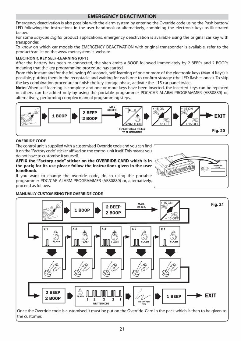
The control unit is supplied with a customised Override code and you can fi nd it on the “Factory code” sticker affi xed on the control unit itself. This means you do not have to customise it yourself. AFFIX the “Factory code” sticker on the OVERRIDE-CARD which is in the pack; for its use please follow the instructions given in the user handbook. If you want to change the override code, do so using the portable programmer PDC/CAR ALARM PROGRAMMER (ABS0889) or, alternatively, proceed as follows.
OVERRIDE CODE
After the battery has been re-connected, the siren emits a BOOP followed immediately by 2 BEEPs and 2 BOOPs meaning that the key programming procedure has started.From this Instant and for the following 60 seconds, self-learning of one or more of the electronic keys (Max. 4 Keys) is possible, putting them in the receptacle and waiting for each one to confi rm storage (the LED fl ashes once). To skip the key combination procedure or fi nish the key storage phase, activate the +15 car panel twice.Note: When self-learning is complete and one or more keys have been inserted, the inserted keys can be replaced or others can be added only by using the portable programmer PDC/CAR ALARM PROGRAMMER (ABS0889) or, alternatively, performing complex manual programming steps.
ELECTRONIC KEY SELF-LEARNING (OPT)
EMERGENCY DEACTIVATIONEmergency deactivation is also possible with the alarm system by entering the Override code using the Push button/LED following the instructions in the user handbook or alternatively, combining the electronic keys as illustrated below.For some EasyCan Digital product applications, emergency deactivation is available using the original car key with transponder. To know on which car models the EMERGENCY DEACTIVATION with original transponder is available, refer to the product/car list on the www.metasystem.it. website
MANUALLY CUSTOMISING THE OVERRIDE CODE
+ 15 ON
+ 15 OFF
2 BEEP2 BOOP
EXIT
1 BOOP
SCRITTURANEW CODE
2 BEEP2 BOOP
X 1 X 2 X 3 X 2 X 1
FLASH FLASH FLASH FLASH FLASH
MAX.60 sec.
1 BEEPFLASH
CODICE SCRITTO
1 2 3 2 1
RIPETERE L OPERAZIONEPER TUTTE LE CHIAVI DA
MEMORIZZARE
MAX60 SEC. + 15 ON
+ 15 OFF
+ 15 ON
+ 15 OFF
2 BEEP2 BOOP EXIT
MEM=1 FLASH
1 BOOP
Fig. 20REPEAT FOR ALL THE KEY TO BE MEMORIZED
WRITTEN CODEWRITING NEW
CODE
Once the Override code is customised it must be put on the Override-Card in the pack which is then to be given to the customer.
OVERRIDECODE
22
COMBINING TO CAN-BUS SYSTEM
13
12
24
1
13
12
24
1
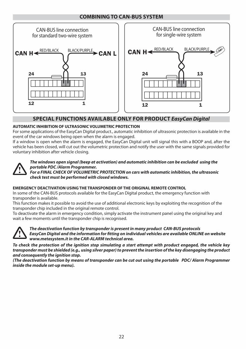
CAN-BUS line connection for standard two-wire system
CAN-BUS line connectionfor single-wire system
RED/BLACK BLACK/PURPLE RED/BLACK BLACK/PURPLE
SPECIAL FUNCTIONS AVAILABLE ONLY FOR PRODUCT EasyCan Digital AUTOMATIC INHIBITION OF ULTRASONIC VOLUMETRIC PROTECTIONFor some applications of the EasyCan Digital product., automatic inhibition of ultrasonic protection is available in the event of the car windows being open when the alarm is engaged.If a window is open when the alarm is engaged, the EasyCan Digital unit will signal this with a BOOP and, after the vehicle has been closed, will cut out the volumetric protection and notify the user with the same signals provided for voluntary inhibition after vehicle closing.
The windows open signal (beep at activation) and automatic inhibition can be excluded using the portable PDC /Alarm Programmer.For a FINAL CHECK OF VOLUMETRIC PROTECTION on cars with automatic inhibition, the ultrasonic check test must be performed with closed windows.
EMERGENCY DEACTIVATION USING THE TRANSPONDER OF THE ORIGINAL REMOTE CONTROLIn some of the CAN-BUS protocols available for the EasyCan Digital product, the emergency function with transponder is available.This function makes it possible to avoid the use of additional electronic keys by exploiting the recognition of the transponder chip included in the original remote control.To deactivate the alarm in emergency condition, simply activate the instrument panel using the original key and wait a few moments until the transponder chip is recognised.
The deactivation function by transponder is present in many product CAN-BUS protocolsEasyCan Digital and the information for fi tting on individual vehicles are available ONLINE on website www.metasystem.it in the CAR-ALARM technical area.
To check the protection of the ignition stop simulating a start attempt with product engaged, the vehicle key transponder must be shielded (e.g., using silver paper) to prevent the insertion of the key disengaging the product and consequently the ignition stop. (The deactivation function by means of transponder can be cut out using the portable PDC/ Alarm Programmer inside the module set-up menu).
23
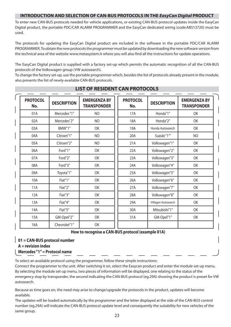
To enter new CAN-BUS protocols needed for vehicle applications, or existing CAN-BUS protocol updates inside the EasyCan Digital product, the portable PDC/CAR ALARM PROGRAMMER and the EasyCan dedicated wiring (code:ABS13720) must be used.
The protocols for updating the EasyCan Digital product are included in the software in the portable PDC/CAR ALARM PROGRAMMER. To obtain the new protocols the programmer must be updated by downloading the new software version from the technical area of the website www.metasystem.it where you will also fi nd all the instructions for update operations.
The EasyCan Digital product is supplied with a factory set-up which permits the automatic recognition of all the CAN-BUS protocols of the Volkswagen group (VW autosearch).To change the factory set-up, use the portable programmer which, besides the list of protocols already present in the module, also presents the list of newly-available CAN-BUS protocols.
INTRODUCTION AND SELECTION OF CAN-BUS PROTOCOLS IN THE EasyCan Digital PRODUCT
PROTOCOL No. DESCRIPTION EMERGENZA BY
TRANSPONDERPROTOCOL
No. DESCRIPTION EMERGENZA BY TRANSPONDER
01A Mercedes “1” NO 17A Honda”1” OK
02A Mercedes”2” NO 18A Honda”2” OK
03A BMW”1” OK 19A Honda Autosearch OK
04A Citroen”1” NO 20A Suzuki “1”” NO
05A Citroen”2” NO 21A Volkswagen”1” OK
06A Ford”1” OK 22A Volkswagen”2” OK
07A Ford”2” OK 23A Volkswagen”3” OK
08A Ford”3” OK 24A Volkswagen”4” OK
09A Toyota”1” OK 25A Volkswagen”5” OK
10A Fiat”1” OK 26A Volkswagen”6” OK
11A Fiat”2” OK 27A Volkswagen”7” OK
12A Fiat”3” OK 28A Volkswagen”8” OK
13A Fiat”4” OK 29A VWagen Autosearch OK
14A Fiat”5” OK 30A Mitsubishi”1” OK
15A GM-Opel”2” OK 31A GM-Opel”1” OK
16A Chevrolet”1” OK
To select an available protocol using the programmer, follow these simple instructions:Connect the programmer to the unit. After switching it on, select the Easycan product and enter the module set-up menu.By selecting the module set-up menu, two pieces of information will be displayed, one relating to the status of the emergency stop by transponder, the second indicating the CAN-BUS protocol (eg.29A) showing the product is preset for VW autosearch.
Because as time goes on, the need may arise to change/upgrade the protocols in the product, updates will become available.The updates will be loaded automatically by the programmer and the letter displayed at the side of the CAN-BUS control number (eg.29A) will indicate the CAN-BUS protocol update level and consequently the suitability for new vehicles of the same group.
LIST OF RESIDENT CAN PROTOCOLS
How to recognise a CAN-BUS protocol (example 01A)
01 = CAN-BUS protocol numberA = revision indexMercedes “1” = Protocol name
24
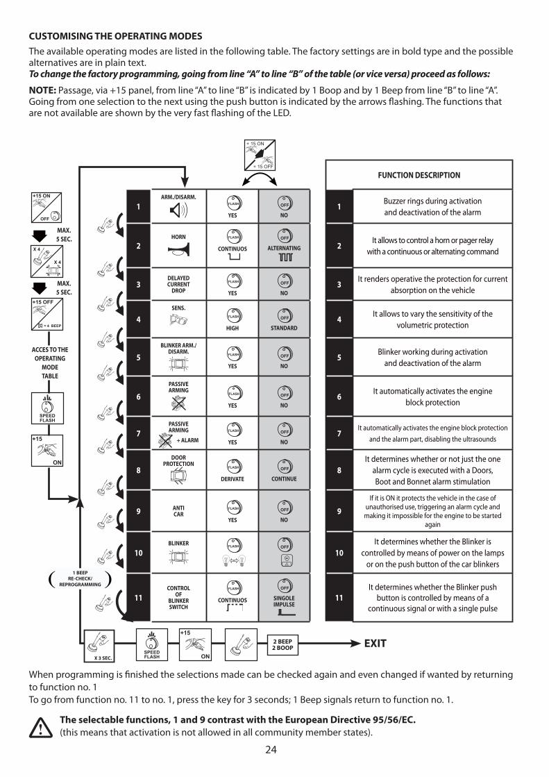
When programming is fi nished the selections made can be checked again and even changed if wanted by returning to function no. 1 To go from function no. 11 to no. 1, press the key for 3 seconds; 1 Beep signals return to function no. 1.
FUNCTION DESCRIPTION
1ARM./DISARM.
FLASH
YES
OFF
NO1
Buzzer rings during activationand deactivation of the alarm
2HORN
FLASH
CONTINUOS
OFF
ALTERNATING 2It allows to control a horn or pager relay
with a continuous or alternating command
3DELAYED CURRENT
DROP FLASH
YES
OFF
NO3
It renders operative the protection for current absorption on the vehicle
4SENS.
FLASH
HIGH
OFF
STANDARD4
It allows to vary the sensitivity of the volumetric protection
5BLINKER ARM./
DISARM.
FLASH
YES
OFF
NO5
Blinker working during activationand deactivation of the alarm
6PASSIVE ARMING
FLASH
YES
OFF
NO6
It automatically activates the engine block protection
7PASSIVE ARMING
+ ALARM
FLASH
YES
OFF
NO7
It automatically activates the engine block protection and the alarm part, disabling the ultrasounds
8DOOR
PROTECTION
FLASH
DERIVATE
OFF
CONTINUE8
It determines whether or not just the one alarm cycle is executed with a Doors, Boot and Bonnet alarm stimulation
9 ANTICAR
FLASH
YES
OFF
NO9
If it is ON it protects the vehicle in the case of unauthorised use, triggering an alarm cycle and
making it impossible for the engine to be started again
10BLINKER
FLASH
OFF
10It determines whether the Blinker is
controlled by means of power on the lamps or on the push button of the car blinkers
11CONTROL
OF BLINKER SWITCH
FLASH
CONTINUOS
OFF
SINGOLE IMPULSE
11It determines whether the Blinker push
button is controlled by means of a continuous signal or with a single pulse
+15
ON
X 4
X 4
MAX.5 SEC.
MAX.5 SEC.
ACCES TO THE OPERATING
MODE TABLE
= 4 BEEP
+15 OFF
SPEEDFLASH
+ 15 ON
+ 15 OFF
SPEEDFLASH
+15
ON
EXIT
OFF
+15 ON
1 BEEPRE-CHECK/
REPROGRAMMING
CUSTOMISING THE OPERATING MODESThe available operating modes are listed in the following table. The factory settings are in bold type and the possible alternatives are in plain text. To change the factory programming, going from line “A” to line “B” of the table (or vice versa) proceed as follows:
NOTE: Passage, via +15 panel, from line “A” to line “B” is indicated by 1 Boop and by 1 Beep from line “B” to line “A”. Going from one selection to the next using the push button is indicated by the arrows fl ashing. The functions that are not available are shown by the very fast fl ashing of the LED.
2 BEEP2 BOOP
The selectable functions, 1 and 9 contrast with the European Directive 95/56/EC. (this means that activation is not allowed in all community member states).
X 3 SEC.
25
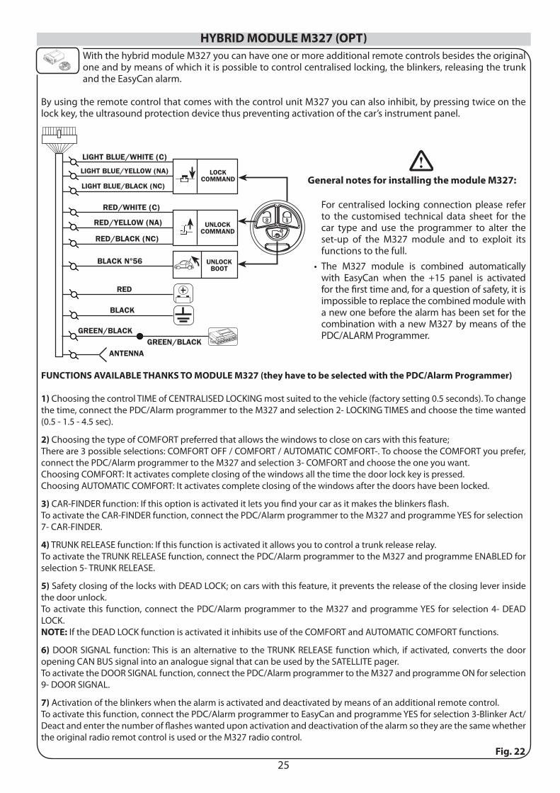
HYBRID MODULE M327 (OPT)With the hybrid module M327 you can have one or more additional remote controls besides the original one and by means of which it is possible to control centralised locking, the blinkers, releasing the trunk and the EasyCan alarm.
By using the remote control that comes with the control unit M327 you can also inhibit, by pressing twice on the lock key, the ultrasound protection device thus preventing activation of the car’s instrument panel.
Fig. 22
General notes for installing the module M327:
For centralised locking connection please refer to the customised technical data sheet for the car type and use the programmer to alter the set-up of the M327 module and to exploit its functions to the full.The M327 module is combined automatically with EasyCan when the +15 panel is activated for the fi rst time and, for a question of safety, it is impossible to replace the combined module with a new one before the alarm has been set for the combination with a new M327 by means of the PDC/ALARM Programmer.
•
FUNCTIONS AVAILABLE THANKS TO MODULE M327 (they have to be selected with the PDC/Alarm Programmer)
1) Choosing the control TIME of CENTRALISED LOCKING most suited to the vehicle (factory setting 0.5 seconds). To change the time, connect the PDC/Alarm programmer to the M327 and selection 2- LOCKING TIMES and choose the time wanted (0.5 - 1.5 - 4.5 sec).
2) Choosing the type of COMFORT preferred that allows the windows to close on cars with this feature; There are 3 possible selections: COMFORT OFF / COMFORT / AUTOMATIC COMFORT-. To choose the COMFORT you prefer, connect the PDC/Alarm programmer to the M327 and selection 3- COMFORT and choose the one you want.Choosing COMFORT: It activates complete closing of the windows all the time the door lock key is pressed.Choosing AUTOMATIC COMFORT: It activates complete closing of the windows after the doors have been locked.
3) CAR-FINDER function: If this option is activated it lets you fi nd your car as it makes the blinkers fl ash.To activate the CAR-FINDER function, connect the PDC/Alarm programmer to the M327 and programme YES for selection 7- CAR-FINDER.
4) TRUNK RELEASE function: If this function is activated it allows you to control a trunk release relay.To activate the TRUNK RELEASE function, connect the PDC/Alarm programmer to the M327 and programme ENABLED for selection 5- TRUNK RELEASE.
5) Safety closing of the locks with DEAD LOCK; on cars with this feature, it prevents the release of the closing lever inside the door unlock.To activate this function, connect the PDC/Alarm programmer to the M327 and programme YES for selection 4- DEAD LOCK. NOTE: If the DEAD LOCK function is activated it inhibits use of the COMFORT and AUTOMATIC COMFORT functions.
6) DOOR SIGNAL function: This is an alternative to the TRUNK RELEASE function which, if activated, converts the door opening CAN BUS signal into an analogue signal that can be used by the SATELLITE pager.To activate the DOOR SIGNAL function, connect the PDC/Alarm programmer to the M327 and programme ON for selection 9- DOOR SIGNAL.
7) Activation of the blinkers when the alarm is activated and deactivated by means of an additional remote control.To activate this function, connect the PDC/Alarm programmer to EasyCan and programme YES for selection 3-Blinker Act/Deact and enter the number of fl ashes wanted upon activation and deactivation of the alarm so they are the same whether the original radio remot control is used or the M327 radio control.
26
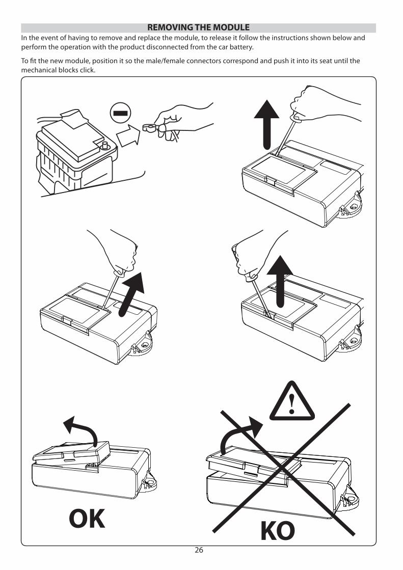
REMOVING THE MODULE
KO
In the event of having to remove and replace the module, to release it follow the instructions shown below and perform the operation with the product disconnected from the car battery.
To fi t the new module, position it so the male/female connectors correspond and push it into its seat until the mechanical blocks click.
OK
27
At the end of installation, the alarm control unit is in the deactivated status and the following operations have to be done: close the doors, bonnet, trunk and windows and do not leave the original remote controls inside the car!
1. Start the car to check that the ignition block connections are working properly;
2. Lock the doors with the original remote control (activation of the alarm system) and check that the car’s original blinkers are fl ashing.
3. The LED fl ashes quickly during the initial immunity time of 25 seconds during which time carry out the following tests (if they are positive they must cause the blinkers to fl ash and the siren to beep once):
• open and close in sequence one door, the bonnet and the trunk;
• turn the ignition key to ON (See page 22 emergency deactivation from original transponder);
• move a hand backwards and forwards in front of the ultrasonic sensors installed;
• stimulate the additional protection modules (e.g. Shock sensor).
Each time the blinkers fl ash the initial immunity time starts again from zero.
4. When the initial immunity time is up, the LED still fl ashes but slower and the triggering of a protection by the alarm generates a 25 second alarm cycle during which the siren emits a characteristic modulated sound, the blinkers fl ash and the horn, if connected, sounds continuously or intermittently, according to how it was programmed.
During the alarm cycle, check correct operation of the protection on the ignition block;
5. Unlock the doors with the original remote control and check that the alarm system is deactivated; when it is deactivated the siren emits a warning BOOP and the LED fl ashes at the sequences foreseen to indicate the alarm memories (see user handbook).
ADDITIONAL CHECKS IN THE CASE OF A COMBINATION WITH THE HYDBRID MODULE M327
1. Close the locks by pressing the close key on the radio control and check: • that the blinkers have fl ashed the number of times corresponding to closing, that the locks are blocked and that the alarm is activated (LED fl ashing quickly). • Press the close key again within the immunity time (25 sec.) and check that the ultrasounds are inhibited (the siren emits 3 beeps meaning the ultrasounds have been inhibited).
2. Release the trunk lock by pressing the trunk key on the remote control and check the lock is released and that the ultrasounds have been inhibited.
3. Release the locks, pressing the open key on the remote control and check that the blinkers have fl ashed the number of times corresponding to opening, that the locks are released and that the alarm is deactivated (LED off ).
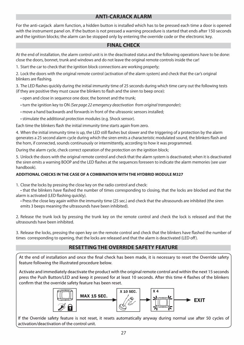
At the end of installation and once the fi nal check has been made, it is necessary to reset the Override safety feature following the illustrated procedure below.
Activate and immediately deactivate the product with the original remote control and within the next 15 seconds press the Push Button/LED and keep it pressed for at least 10 seconds. After this time 4 fl ashes of the blinkers confi rm that the override safety feature has been reset.
FINAL CHECK
RESETTING THE OVERRIDE SAFETY FEATURE
MAX 15 SEC.X 10 SEC. X 4
EXIT
ANTI-CARJACK ALARMFor the anti-carjack alarm function, a hidden button is installed which has to be pressed each time a door is opened with the instrument panel on. If the button is not pressed a warning procedure is started that ends after 150 seconds and the ignition blocks; the alarm can be stopped only by entering the override code or the electronic key.
If the Override safety feature is not reset, it resets automatically anyway during normal use after 50 cycles of activation/deactivation of the control unit.