01 HB2500 EN R2
30
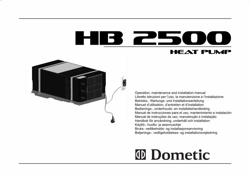
HB 2500 Operation, maintenance and installation manual Libretto istruzioni per l’uso, la manutenzione e l’installazione Betriebs-, Wartungs- und Installationsanleitung Manuel d’utilisation, d’entretien et d’installation Bedienings-, onderhouds- en installatiehandleiding Manual de instrucciones para el uso, mantenimiento e instalación Manual de instruções de uso, manutenção e instalação Handbok för användning, underhåll och installation Käyttö-, huolto- ja asennusohje Bruks- vedlikeholds- og installasjonsanvisning Betjenings-, vedligeholdelses- og installationsvejledning HEAT PUMP
Transcript of 01 HB2500 EN R2
HB 2500
Operation, maintenance and installation manualLibretto istruzioni per l’uso, la manutenzione e l’installazioneBetriebs-, Wartungs- und InstallationsanleitungManuel d’utilisation, d’entretien et d’installationBedienings-, onderhouds- en installatiehandleiding Manual de instrucciones para el uso, mantenimiento e instalación Manual de instruções de uso, manutenção e instalação Handbok för användning, underhåll och installation Käyttö-, huolto- ja asennusohje Bruks- vedlikeholds- og installasjonsanvisning Betjenings-, vedligeholdelses- og installationsvejledning
HEAT PUMP
ENGLISH With Dometic at home everywhere. Thank you for your decision to buy an Dometic product. They all have been specially conceived for your vehicle, matching totally the requirements of leisure on wheels - with more than 75 years of experience, the most advanced technology, fi rst-rate materials, superb workmanship, functional design and a care for the environment. The unique Dometic EuroService Guarantee offers you additional peace of mind - ensuring that you will derive comfort everywhere from your Dometic products
ITALIANO Con Dometic come a casa, ovunque. Vi ringraziamo per averci scelto. I prodotti Dometic sono stati espressamente concepiti per il Vostro veicolo; soddisfacendo completamente le esigenze del tempo libero, sui mezzi mobili, con un’esperienza di oltre 75 anni, la tecnologia più avanzata, materiali di prima qualità, superba squadra di tecnici nonché design funzionale ed attenzione per l’ambiente. Usufruite del Servizio di Garanzia Europea che Vi offre completa tranquillità assicurandoVi che trarrete grande comfort ovunque grazie ai “Vostri” prodotti Dometic
DEUTSCH Mit Dometic überall wie zu Hause. Wir danken Ihnen für Ihre Wahl. Die Dometic-Produkte wurden speziell für Ihr Fahrzeug entwickelt und tragen den Erfordernissen der Freizeit auf Rädern voll Rechnung - mit einer mehr als 75-jährigen Erfahrung, modernster Technologie, erstklassigen Materialien, einem hervorragenden Technikerteam, funktionellem Design und Umweltfreundlichkeit. Nutzen Sie die EuroService-Garantie, mit der Sie ganz ruhig fahren und die Ihnen überall dank “Ihren” Dometic-Produkten größten Komfort sichert
FRANÇAIS Partout avec Dometic. Merci d’avoir choisi un produit Dometic. Il a été spécialement conçu pour votre véhicule complétant totalement la gamme d’équipements de votre véhicule de loisirs. Dometic, c’est aussi, 75 ans d’expérience, une technologie avancée, du matériel de premier choix, un design fonctionnel et la protection de l’environnement. La garantie Européenne Dometic vous offre, où que vous soyez, la possibilité de profi ter partout de votre matériel.
NEDERLANDS Met Dometic voelt u zich overal thuis. Wij danken u voor uw besluit een product van Do-metic aan te schaffen. Al onze producten zijn speciaal ontworpen voor uw voertuig en voldoen volledig aan de vereisten die worden gesteld aan een vakantie onderweg - met meer dan 75 jaar ervaring, de meest geavanceerde technologie, uitstekende materialen, voortreffelijk vakmanschap, functioneel design en zorg voor het milieu. Bovendien biedt de unieke Dometic EuroService Garantie u extra zekerheid - zodat u er zeker van bent dat u overal kunt genieten van het comfort die producten van Dometic u bieden.
ESPAÑOL Con Dometic en todas partes como en casa. Le agradecemos su elección. Los productos Dometic han sido expresamente concebidos para su vehículo; satisfaciendo totalmente las exigencias del tiempo libre, en medios móviles, con una experiencia de más de 75 años, la tecnología más avanzada, materiales de primera calidad, soberbio equipo de técnicos así como design funcional y respeto al medio ambiente. Disfruten del Servicio de Garantía Europea que le ofrece tranquilidad absoluta, asegurándole que obtendrá gran confort en cualquier lugar
gracias a sus productos Dometic. La garantie Européenne Dometic vous offre, où que vous soyez, la possibilité de profi ter partout de votre matériel.
PORTUGUÊS Com Dometic, em todo o lado como em casa. Agradecemos a sua escolha. Os produtos Dometic foram expressamente concebidos para o seu veículo; satisfazendo totalmente as exigências do tempo livre, em meios móveis, com uma experiência de mais de 75 anos, a tecnologia mais avançada, materiais de primeira qualidade, uma excelente equipa de técnicos e um design funcional e respeito pelo ambiente. Aproveite o Serviço de Garantia Europeia, que lhe oferece uma tranquilidade absoluta e lhe assegura que obterá um grande conforto em qualquer lugar graças aos seus produtos Dometic.
SVENSKA Med Dometic är Du hemma överallt. Tack för Ditt beslut att köpa en Dometicprodukt. De har utvecklats speciellt för Din husvagn eller husbil och lever upp till alla de krav för fritid på hjul -med mer än 75 års erfarenhet, avancerad teknologi, förstklassigt material, oöverträffat hantverk och design samt omtanke om miljön. Den unika Dometic Europagararantin ger Dig trygghet om något skulle hända.
SUOMI Dometic - kotonaan kaikkialla. Olemme iloisia siitä, että olet valinnut Dometic tuotteen. Tuotteemme on kehitetty yli 75 vuoden kokemuksella liikkuvan lomanviettäjän tarpeisiin ja valmistettu ensiluokkaisista materiaaleista uusimmalla, ympäristöä säästävällä tekniikalla, toimivalla muotoilulla ja korkealla ammattitaidolla. Dometic tuotteita voit käyttää luottavaisin mielin.Ainutlaatuinen Dometic EuroService -takuu ja laaja huoltoverkosto varmistavat., että saat apua ongelmatilanteissa myös matkasi varrella.
NORSK Med Dometic kan du føle deg hjemme overalt. Takk for at du bestemte deg for å kjøpe et produkt fra Dometic. Alle våre produkter er utviklet spesielt for ditt kjøretøy og lever fullt opp til alle krav om bekvemmelighet i din fritid - basert på mer enn 75 års erfaring, den mest avanserte teknologi, førsteklasses materialvalg og håndverk, funksjonelt design og omtanke for miljøet. Den unike Dometic EuroService-garantien gir deg trygghet og sikrer komfort uansett hvor du måtte befi nne deg.
DANSK Med Dometic kan du føle dig hjemme overalt. Tak for din beslutning om at købe et Dometic produkt. De er alle blevet specielt udviklet til dit køretøj og lever fuldt ud op til kravene om fritid på hjul med mere end 75 års erfaring, den mest avancerede teknologi, førsteklasses materialer, uovertruffent håndværk, funktionelt design og omtanke for miljøet. Den unikke Dometic EuroService Garanti giver dig yderligere ro i sjælen og sikrer, at du takket være dine Dometic produkter vil opleve stor komfort, uanset hvor du befi nder dig.
©DOMETIC - 2007 All rights reserved - Printed in Italy -
No part of this manual may be duplicated, copied or published in any form without written authorization from DOMETICThe fi gures, descriptions, references and technical data contained in this manual are merely guidelines and are not binding.
DOMETIC reserves the right to make all the modifi cations it may deem fi t, at any time and without notice, in a constant effort to improve quality and safety, without undertaking to update this manual each time.
Keep this document for future reference.
Validity of warranty
“The Product is guaranteed in accordance with the law and regulations made after assimilation of Directive 1999/44/EC.”
The manufacturer’s warranty is expressly excluded in the event of breakage and/or abnormal operation of the Product caused by and/or depending on incorrect assembly.
It is the Consumer’s right to have the Product fi tted by authorized dealers that are not subordinate to Dometic.
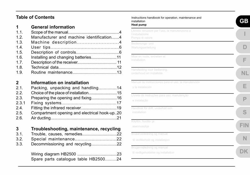
1 General information1.1. Scope of the manual.............................................41.2. Manufacturer and machine identification......41.3. Machine descr ipt ion.. . . . . . . . . . . . . . . . . . . . . . . . . .41.4. User tips................................................61.5. Description of controls..................................61.6. Installing and changing batteries......................11 1.7. Description of the receiver................................... 111.8. Technical data..................................................121.9. Routine maintenance....................................13 2 Information on installation2.1. Packing, unpacking and handling..............142.2. Choice of the place of installation..........................152.3. Preparing the opening and fi xing......................162.3.1 Fixing systems..........................................172.4. Fitting the infrared receiver...............................192.5. Compartment opening and electrical hook-up..202.6. Air ducting.........................................................21
3 Troubleshooting, maintenance, recycling3.1. Trouble, causes, remedies.............................223.2. Special maintenance..............................223.3. Decommissioning and recycling......................22
Wiring diagram HB2500 ..................................23 Spare parts catalogue table HB2500.........24
Table of Contents Instructions handbook for operation, maintenance andinstallationHeat pump
GB
I
D
FHandleiding voor bediening,onderhoud en installatie NLManual de instrucciones para el uso, la manutención
y la instalación ELivrete de instruções para uso, manutenção
e instalação PHandbok för drift, underhåll och installation SKäyttö-, huolto- ja
asennusohje FINBrukerveiledning og manual
til vedlikehold og installasjon N
DK
Bedienungs- undWartungsanleitung
Mise en route, entretien etinstallation
Brugervejledning og manual
til vedligeholdelse og installation
Libretto istruzioni per l’uso, la manutenzione el’installazionePompa di calore

HB2500 4 Operating instructions for users
1.1. Scope of the manualThis manual has been drawn up by the Manufacturer and is an integral part of the machine.The information it contains, if observed, can guarantee correct use of the machine.The fi rst part of the manual is for the user , while the second part is for the expert personnel who install the machine.
To highlight some parts of the text, the following symbols have been added:
This operation may be a source of danger.Useful advice.Information on being environment friendly.
1.2. Manufacturer and machine identifi cation
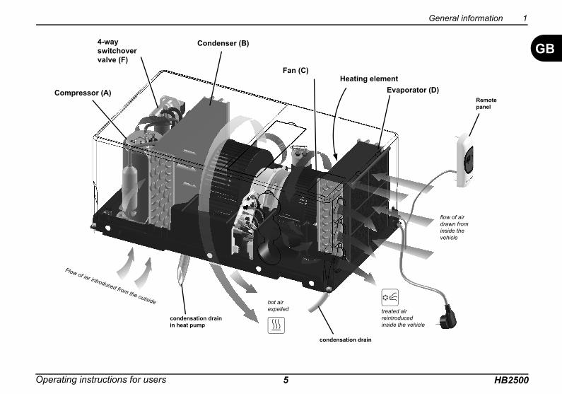
1.3. Machine descriptionThis machine has been designed and built to be installed on vehicles (motor homes, caravans, special vehicles, etc.) in order to improve the internal temperature. When the weather is hot it supplies cool and dehumidifi ed air; when the weather is cold it supplies hot air without however replacing the vehicle’s original heating system. In both cases the air temperature is adjustable.
Cool air - Description of operation (FIG. 5)The system is composed of: compressor (A), condenser (B), evaporator (D) a 4-way switchover valve (F) and the pressurized refrigerant.The refrigerant, by changing physical state from liquid to gas, heats or cools the components through which it passes.The evaporator that has been made cold is crossed by the internal air blown by the fan (C).It comes out cooled and dehumidifi ed. This action protracted over time creates a reduction in the temperature inside the vehicle.
Hot air - Description of operation (FIG. 5)The refrigerating cycle is reversed by the 4-way valve switching over (F); the internal coil changes from evaporator to condenser, thereby heating the air passing through it.The system is equipped with a heating element (E) that increases the effi ciency of the heat pump at low temperatures.
1 General information
Identifi cation of the manufacturerConformity markings
Model/Serial number
Year of manufactureTechnical data
GB
Operating instructions for users HB25005
General information 1
GB
Compressor (A)
Condenser (B)
Evaporator (D)Heating element
condensation drain
Fan (C)
Flow of iar introduced from the outside
treated airreintroducedinside the vehicle
hot airexpelled
fl ow of air drawn from inside the vehicle
condensation drainin heat pump
4-wayswitchovervalve (F)
Remote panel
HB2500 6 Operating instructions for users
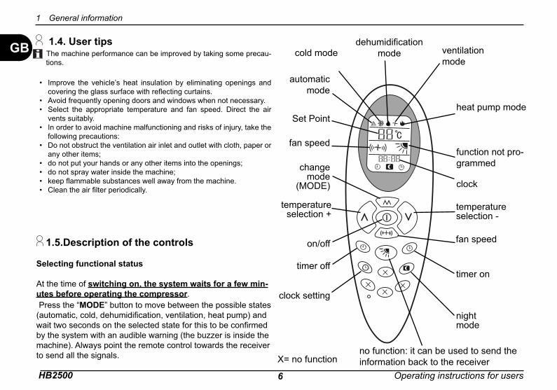
GB 1.4. User tips The machine performance can be improved by taking some precau-tions.
Improve the vehicle’s heat insulation by eliminating openings and covering the glass surface with refl ecting curtains.Avoid frequently opening doors and windows when not necessary.Select the appropriate temperature and fan speed. Direct the air vents suitably.In order to avoid machine malfunctioning and risks of injury, take the following precautions:Do not obstruct the ventilation air inlet and outlet with cloth, paper or any other items;do not put your hands or any other items into the openings;do not spray water inside the machine;keep fl ammable substances well away from the machine.Clean the air fi lter periodically.
•
••
•
•
••••
Selecting functional status
At the time of switching on, the system waits for a few min-utes before operating the compressor. Press the “MODE” button to move between the possible states (automatic, cold, dehumidifi cation, ventilation, heat pump) and wait two seconds on the selected state for this to be confi rmed by the system with an audible warning (the buzzer is inside the machine). Always point the remote control towards the receiver to send all the signals.
1.5.Description of the controls
1 General information
on/off fan speed
change mode
(MODE)
automatic mode
temperature selection -
temperature selection +
cold mode
Set Pointheat pump mode
dehumidifi cationmode ventilation
mode
clock
timer offtimer on
clock setting
nightmode
fan speedfunction not pro-grammed
X= no functionno function: it can be used to send the information back to the receiver
Operating instructions for users HB25007
General information 1
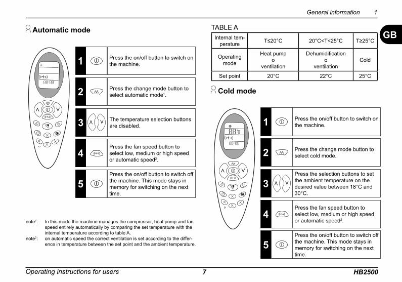
GB Automatic mode
Cold mode
Press the on/off button to switch on the machine. 1
Press the change mode button to select automatic mode1.2
Press the fan speed button to select low, medium or high speed or automatic speed2.
4
Press the on/off button to switch off the machine. This mode stays in memory for switching on the next time.
5
note1: In this mode the machine manages the compressor, heat pump and fan speed entirely automatically by comparing the set temperature with the internal temperature according to table A.
note2: on automatic speed the correct ventilation is set according to the differ-ence in temperature between the set point and the ambient temperature.
Press the on/off button to switch on the machine.1
Press the selection buttons to set the ambient temperature on the desired value between 18°C and 30°C.
3
Press the fan speed button to select low, medium or high speed or automatic speed2.
4
Press the on/off button to switch off the machine. This mode stays in memory for switching on the next time.
5
Press the change mode button to select cold mode.2
The temperature selection buttons are disabled.3
Internal tem-perature T≤20°C 20°C<T<25°C T≥25°C
Operatingmode
Heat pumpo
ventilation
Dehumidifi cationo
ventilationCold
Set point 20°C 22°C 25°C
TABLE A
HB2500 8 Operating instructions for users
GB
1 General information
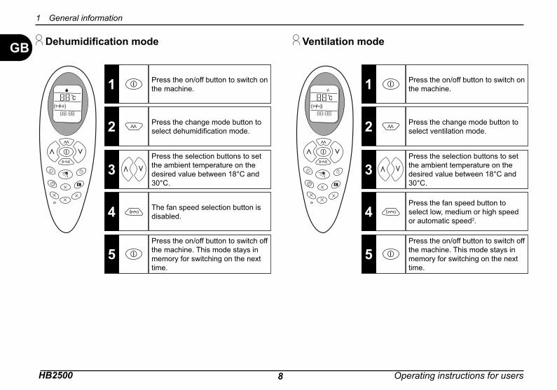
Dehumidifi cation mode
Press the on/off button to switch on the machine.1
Press the selection buttons to set the ambient temperature on the desired value between 18°C and 30°C.
3
The fan speed selection button is disabled.4
Press the on/off button to switch off the machine. This mode stays in memory for switching on the next time.
5
Press the change mode button to select dehumidifi cation mode.2
Ventilation mode
Press the on/off button to switch on the machine.1
Press the selection buttons to set the ambient temperature on the desired value between 18°C and 30°C.
3
Press the fan speed button to select low, medium or high speed or automatic speed2.
4
Press the on/off button to switch off the machine. This mode stays in memory for switching on the next time.
5
Press the change mode button to select ventilation mode.2
Operating instructions for users HB25009
GB
General information 1
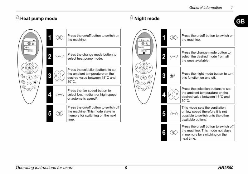
Heat pump mode
Press the on/off button to switch on the machine.1
Press the selection buttons to set the ambient temperature on the desired value between 18°C and 30°C.
3
Press the fan speed button to select low, medium or high speed or automatic speed2.
4
Press the on/off button to switch off the machine. This mode stays in memory for switching on the next time.
5
Press the change mode button to select heat pump mode.2
Night mode
Press the on/off button to switch on the machine.1
Press the selection buttons to set the ambient temperature on the desired value between 18°C and 30°C.
4
This mode sets the ventilation on low speed therefore it is not possible to switch onto the other available options.
5
Press the on/off button to switch off the machine. This mode not stays in memory for switching on the next time.
6
Press the change mode button to select the desired mode from all the ones available.
2
Press the night mode button to turn this function on and off.3
HB2500 10 Operating instructions for users
GB
1 General information
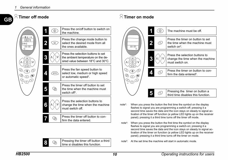
Timer off mode
Press the on/off button to switch on the machine.1
Press the fan speed button to select low, medium or high speed or automatic speed2.
4
Press the timer off button to set the time when the machine must switch off3.
5
Press the change mode button to select the desired mode from all the ones available.
2Press the selection buttons to set the ambient temperature on the de-sired value between 18°C and 30°C.
3
Press the selection buttons to change the time when the machine must switch off.
6
Press the timer off button to con-fi rm the data entered.7
Pressing the timer off button a third time si disables this function.8
The machine must be off.1Press the timer on button to set the time when the machine must switch on4.
2
Press the selection buttons to change the time when the machine must switch on.
3
note3: When you press the button the fi rst time the symbol on the display fl ashes to signal you are programming a switch-off; pressing it a second time saves the data and the icon stays on steady to signal ac-tivation of the timer off function (a yellow LED lights up on the receiver panel); pressing it a third time turns off the timer off mode.
note4: When you press the button the fi rst time the symbol on the display fl ashes to signal you are programming a switch-on; pressing it a second time saves the data and the icon stays on steady to signal ac-tivation of the timer on function (a yellow LED lights up on the receiver panel); pressing it a third time turns off the timer on mode.
note5: At the set time the machine will start in automatic mode.
Press the timer on button to con-fi rm the data entered5.4
Pressing the timer on button a third time disables this function.5
Timer on mode

Operating instructions for users HB250011
GB
General information 1
1.6. Installing and changing the remote control batteries
Take off the battery cover. Insert the two batteries supplied (size AAA), paying attention to their polarity. Fit the battery cover back on. Check the remote control works properly by pressing the on button: if, on pressing the button, no icon appears on the display then you need to re-install the batteries checking their polarity. The machine is connected to the power supply and ready for use.
display
blue LED
green LED yellow LED
red LED
signal receiver
1.7. Description of the receiver
The receiver panel is composed of a display and four LEDs of dif-ferent colours. The display switches on whenever it receives pulses from the remote control to display the temperature setting; after a few moments the ambient temperature is displayed and then it switches off. The four LEDs signal the machine’s functional status. The red LED signals power on. The blue LED signals that the machine is working in night mode. The green LED signals that the compressor is working. The yellow LED: on steady signals that one of the timer modes has been turned on; blinking signals that the ventilation is temporarily suspended.

HB2500 12 Operating instructions for users
GB 1.8. Technical data
1 General information
27
710
57
153
400
3028
0
Description Unit of measurement
ModelHB 2500
Refrigerant type/quantity see machine dataplateRefrigerating capacity Watt/h 2500**Heating capacity Watt/h 3000**Consumption when cooling A-Watt 3.9 - 900Consumption when heating A-Watt 4.8 - 1100Breakaway current A 20 (150ms)Additional heating element Watt 500Electricity supply V-Hz 220÷240 - 50Protection class IP X5Treated volume of air (max) m3/h 350Max volume (recommended with insulated walls) m3 30Weight kg 24.9E.E.R. - 2.5C.O.P. - 2.6Ventilation Speed no. 3Operating temperature °C from -15 to +40
1100W (600W + 500W*)
3000W (2500W + 500W*)
with no CFCs
* Additional heating element
** according to EN 14511
Operating instructions for users HB250013
GB
General information 1
Petrol
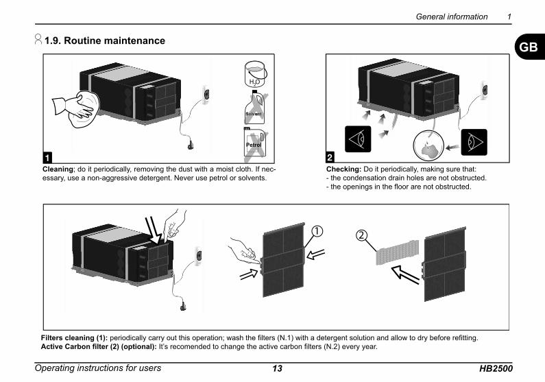
1.9. Routine maintenance
Cleaning; do it periodically, removing the dust with a moist cloth. If nec-essary, use a non-aggressive detergent. Never use petrol or solvents.
Checking: Do it periodically, making sure that:- the condensation drain holes are not obstructed.- the openings in the fl oor are not obstructed.
Filters cleaning (1): periodically carry out this operation; wash the fi lters (N.1) with a detergent solution and allow to dry before refi tting.Active Carbon fi lter (2) (optional): It’s recomended to change the active carbon fi lters (N.2) every year.
HB2500 14 Operating instructions for users
GBInstallation can be performed by persons with specifi c technical knowledge. In addition to this requirement, installers must have adequate working conditions in order to ensure their own safety and that of others.
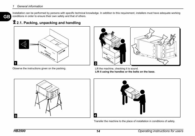
2.1. Packing, unpacking and handling
Observe the instructions given on the packing. Lift the machine, checking it is sound.Lift it using the handles or the belts on the base.
Transfer the machine to the place of installation in conditions of safety.
1 General information
Operating instructions for users HB250015
Information on installation 2
GB 2.2. Choice of the place of installationTo accomplish uniform climate control in a vehicle, the machine must be installed as near the middle as possible, in a housing or a similar device.
Position the machine so as to ensure easy access for servicing and to facilitate disassembly and installation.
Place the assembly template in the compartment intended for installa-tion and check the space available for the openings in the fl oor.
To minimize the transmission of noise and vibration during operation, the machine must have a minimum clearance on each side of 30 mm from the walls and fi ttings, The machine must be installed on the fl oor.
To make renewing the fi lter easier, keep a distance of 200 mm between the front of the machine and the walls of the compartment.
If fi tting in external compartments (e.g., false bottoms), the air to be treated must be drawn in from the vehicle’s passenger compartment.
Drawing in outside air can signifi cantly reduce the power of the system.
HB2500 16 Operating instructions for users
GB
2 Information on installation
30mm
200mm
30mm710
400
187
280
193
123
267.516
65.533
Ø 55
207,
5
609
87
141.
5
Ø 20
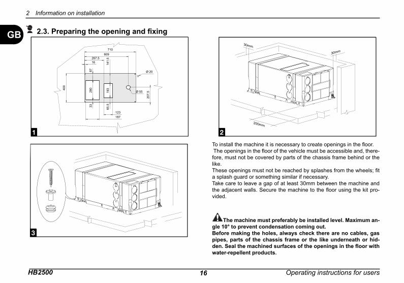
2.3. Preparing the opening and fi xing
To install the machine it is necessary to create openings in the fl oor. The openings in the fl oor of the vehicle must be accessible and, there-fore, must not be covered by parts of the chassis frame behind or the like.These openings must not be reached by splashes from the wheels; fi t a splash guard or something similar if necessary. Take care to leave a gap of at least 30mm between the machine and the adjacent walls. Secure the machine to the fl oor using the kit pro-vided.
The machine must preferably be installed level. Maximum an-gle 10° to prevent condensation coming out.Before making the holes, always check there are no cables, gas pipes, parts of the chassis frame or the like underneath or hid-den. Seal the machined surfaces of the openings in the fl oor with water-repellent products.
Operating instructions for users HB250017
Information on installation 2
GB
x4
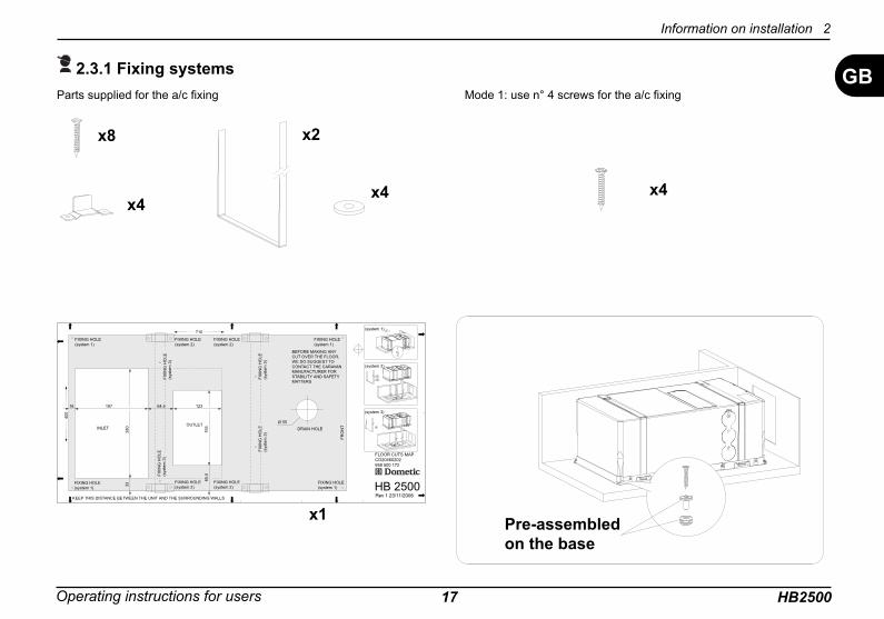
Mode 1: use n° 4 screws for the a/c fi xing
Pre-assembled on the base
2.3.1 Fixing systems
x8
x4x4
Parts supplied for the a/c fi xing
x2
Ø 55INLET
18716 64.5 123
710
193
65.5
280
400
33
FIXING HOLE(system 1)
(system 1)
(system 2)
(system 3)
KEEP THIS DISTANCE BETWEEN THE UNIT AND THE SURROUNDING WALLS
FIXING HOLE(system 1)
FIXING HOLE(system 1)
FIXING HOLE(system 2)
FIXING HOLE(system 2)
FIXING HOLE(system 2)
FIX
ING
HO
LE(s
yste
m 3
)
FIX
ING
HO
LE(s
yste
m 3
)
FIX
ING
HO
LE(s
yste
m 3
)FI
XIN
G H
OLE
(sys
tem
3)
FIXING HOLE(system 2)
FIXING HOLE(system 1)
OUTLETDRAIN HOLE
FRO
NT
FLOOR CUTS MAPCO20460202958 500 172
HB 2500
BEFORE MAKING ANY CUT OVER THE FLOOR, WE DO SUGGEST TO CONTACT THE CARAVAN MANUFACTURER FOR STABILITY AND SAFETY MATTERS
Rev 1 23/11/2006
x1

HB2500 18 Operating instructions for users
GB
2 Information on installation
x8
x4
x2
x4
x4
x2
Mode 2: use n° 8 screws, n° 4 brackets and n° 2 belts for the a/c fi xing Mode 3: use n° 4 screws and n° 4 washers for the a/c fi xing
Operating instructions for users HB250019
Information on installation 2
GB
20 mm
X
X + 40 mm
57
153
Y
Y +
125
mm
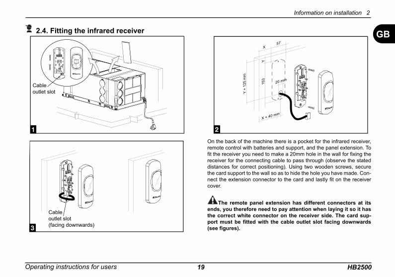
2.4. Fitting the infrared receiver
On the back of the machine there is a pocket for the infrared receiver, remote control with batteries and support, and the panel extension. To fi t the receiver you need to make a 20mm hole in the wall for fi xing the receiver for the connecting cable to pass through (observe the stated distances for correct positioning). Using two wooden screws, secure the card support to the wall so as to hide the hole you have made. Con-nect the extension connector to the card and lastly fi t on the receiver cover.
The remote panel extension has different connectors at its ends, you therefore need to pay attention when laying it so it has the correct white connector on the receiver side. The card sup-port must be fi tted with the cable outlet slot facing downwards (see fi gures).
Cable outlet slot
Cableoutlet slot(facing downwards)
HB2500 20 Operating instructions for users
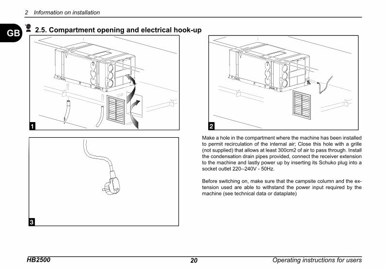
GB 2.5. Compartment opening and electrical hook-up
Make a hole in the compartment where the machine has been installed to permit recirculation of the internal air; Close this hole with a grille (not supplied) that allows at least 300cm2 of air to pass through. Install the condensation drain pipes provided, connect the receiver extension to the machine and lastly power up by inserting its Schuko plug into a socket outlet 220--240V - 50Hz.
Before switching on, make sure that the campsite column and the ex-tension used are able to withstand the power input required by the machine (see technical data or dataplate)
2 Information on installation

Operating instructions for users HB250021
GB 2.6. Air ductingMake the air ducting with trade parts that are not supplied. It is recommended to use cardboard pipe for air conditioning with an aluminium core and external covering of PVC with an inside nominal diameter of 60 mm. This pipe has an outside diameter of 65mm.The ventilation pipes are joined by pressing them together thanks to the tapered hole on the air outlet.The pipes can be connected either on the outlet on the coil side or, by removing the guard and closing the front holes, on the side outlet.
To achieve the best effi ciency it is recommended to: - lay the air pipes so they are as short and straight as pos-
sible;- not use pipes any longer than 5m;- not place the pipes near sources of heat.
The recirculation air is drawn in through a grille or through other openings with a total cross-section of at least 300 cm2. The recirculation air opening must be made near the machine; if this is not the case then make sure that the air fl ow cannot be obstructed by anything (if necessary, create an air duct be-tween the opening and the machine).The recirculation air must be taken from inside the passenger compartment; if it were taken from the outside then machine effi ciency would suffer.
Information on installation 2
HB2500 22 Operating instructions for users
GB
SOLU
TIO
N
the
tem
pera
ture
is lo
wer
than
18°
C
the
tem
pera
ture
is h
ighe
r tha
n 30
°C
chec
k th
e Se
t Poi
nt te
mpe
ratu
re
Def
ectiv
e th
erm
al p
rote
ctio
n
The
Mod
e bu
tton
is n
ot in
the
right
pos
ition
dam
aged
ele
ctric
hea
ting
elem
ent
low
gas
cha
rge
dam
aged
com
pres
sor
dirt
y he
at e
xcha
nge
coils
defe
ctiv
e in
tern
al fa
n
obst
ruct
ed a
ir fi l
ter
defe
ctiv
e ex
tern
al fa
ns
clog
ged
cond
ensa
tion
drai
n ho
les
dam
aged
4-w
ay v
alve
no p
ower
arr
ives
volta
ge to
o lo
w (l
ess
than
200
V)
defe
ctiv
e el
ectr
ic c
onde
nser
CAUSE
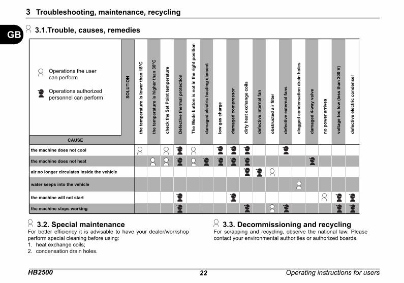
the machine does not cool
the machine does not heat
air no longer circulates inside the vehicle
water seeps into the vehicle
the machine will not start
the machine stops working
Operations the user can perform
Operations authorized personnel can perform
3.1.Trouble, causes, remedies
3.2. Special maintenanceFor better effi ciency it is advisable to have your dealer/workshop perform special cleaning before using:
heat exchange coils;condensation drain holes.
1.2.
3.3. Decommissioning and recyclingFor scrapping and recycling, observe the national law. Please contact your environmental authorities or authorized boards.
3 Troubleshooting, maintenance, recycling
HB250023
GB
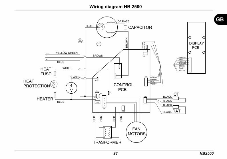
Wiring diagram HB 2500
VIOLETBLUEGREENORANGE
DISPLAY PCB
CONTROL PCB
TRASFORMER
HEATER
HEATPROTECTION
HEATFUSE
CAPACITOR
ICT
RAT
F
GND
N
FANMOTORS
N1
HMLC-N
N2
CN4
S
4V
N3
CN5
CN6
CNR
CN2
CN3
4V
BLUE
RE
D
RE
D
RE
D
RE
D
BLUE
BLUE
BLACK
BLACK
VIOLETBLUEGREENYELLOWORANGEREDBROWN
YE
LLO
W
RE
DB
RO
WN
BLACK
BLACK
BLACK
WHITE
BROWN
BR
OW
N
ORANGE
YELLOW GREEN
HB2500 24
GB
30 31
2845 14
46
7
7
32
4447
50
58
59
20
21
56
24 926
13
34
3511
51
6
12
36
43
36
48
373
2539
5753
5418
19
4
49
522
15
10 27
8
8
16
17
22
23
29
4
4
1
3837
40 42
41
37 38385
33
55
60
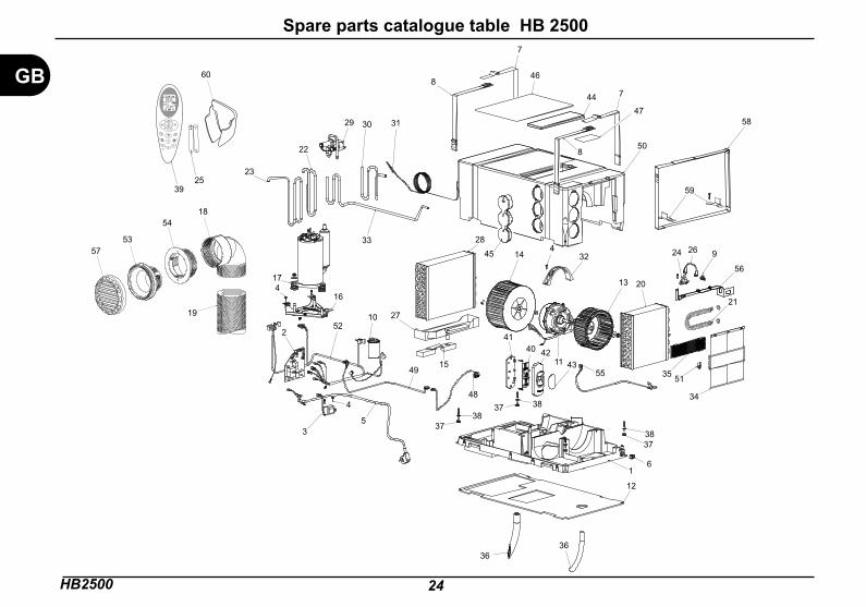
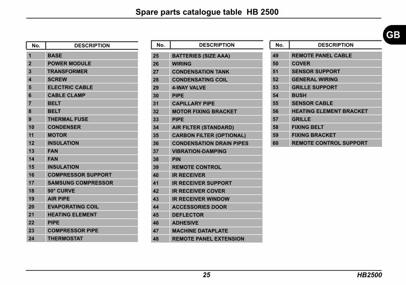
Spare parts catalogue table HB 2500
HB250025
No. DESCRIPTION
1 BASE2 POWER MODULE 3 TRANSFORMER4 SCREW 5 ELECTRIC CABLE6 CABLE CLAMP 7 BELT8 BELT9 THERMAL FUSE10 CONDENSER11 MOTOR12 INSULATION 13 FAN 14 FAN15 INSULATION16 COMPRESSOR SUPPORT17 SAMSUNG COMPRESSOR18 90° CURVE19 AIR PIPE20 EVAPORATING COIL 21 HEATING ELEMENT 22 PIPE 23 COMPRESSOR PIPE24 THERMOSTAT
25 BATTERIES (SIZE AAA)26 WIRING 27 CONDENSATION TANK28 CONDENSATING COIL29 4-WAY VALVE 30 PIPE31 CAPILLARY PIPE 32 MOTOR FIXING BRACKET33 PIPE34 AIR FILTER (STANDARD)35 CARBON FILTER (OPTIONAL)36 CONDENSATION DRAIN PIPES37 VIBRATION-DAMPING38 PIN 39 REMOTE CONTROL40 IR RECEIVER 41 IR RECEIVER SUPPORT42 IR RECEIVER COVER43 IR RECEIVER WINDOW44 ACCESSORIES DOOR45 DEFLECTOR46 ADHESIVE47 MACHINE DATAPLATE48 REMOTE PANEL EXTENSION
49 REMOTE PANEL CABLE50 COVER51 SENSOR SUPPORT52 GENERAL WIRING53 GRILLE SUPPORT54 BUSH55 SENSOR CABLE56 HEATING ELEMENT BRACKET57 GRILLE58 FIXING BELT59 FIXING BRACKET60 REMOTE CONTROL SUPPORT
No. DESCRIPTION No. DESCRIPTIONGB
Spare parts catalogue table HB 2500

Smaltimento delle apparecchiature obsoleteDisposal of your old appliance
Entsorgung von AltgerätenÉlimination des appareillages obsolètes
Como deshacerse de aparatos elèctricos y electrónicos fiejosEliminação do seu antigo aparelho
IT UK DEDisposal of your old appliance1. When this crossed-out bin sym-bol appears on a product it means that the product is covered by Eu-ropean Directive 2002/96/EC.2. All electrical and electronic prod-ucts should be disposed of sepa-rately from the municipal waste stream via specific collection facili-ties designated by the government or the local authorities.3. Proper disposal of your old ap-pliance will help prevent potential negative consequences for the en-vironment and human health.4. For more detailed information about disposal of your old appli-ance, please contact your munici-pality, the waste disposal service or the shop where you purchased the product.
FR ESComo deshacerse de aparatos elèctricos y electrónicos fiejos1. Si en un profucto aparece el símbolo de un contenedor de bas-ura tachado, significa que èste se acoge a la Directiva 2002/96/EC.2. Los aparatos elèctricos no se deben desechar junto con los residuos domèsticos, sino a travès de puntos de recogida designados por el gobierno o las autoridades locales.3. La correcta recogida y tratami-ento de los dispositivos inserivbles contribuye a evitar riesgos poten-ciales para el medio ambiente y la salud pública.4. Para obtener más información sobre cómo deshacerse de sus aparatos elèctricos y electrónicos viejos, póngase en contacto con su ayuntamiento, el servicio de recog-ida de basuras o el establecimiento donde adquirió el producto.
Entsorgung von Altgeräten.1. Wenn dieses Symbol eines durchgestrichenen Abfalleimers auf einem Produkt angebracht ist, unterliegt dieses Produkt der euro-päischen Richtlinie 2002/96/EC.2. Alle Elektro–und Elektronik-Alt-geräte müssen getrennt vom Haus-müll über dafür staatlich vorgese-hene Stellen entsorgt werden.3. Eine ordnungsgemäße Entsor-gung des Altgeräts trägt dazu bei, Schäden an der Umwelt und der menschlichen Gesundheit zu ver-meiden.4. Weitere Informationen zur Ent-sorgung des Altgeräts erhalten Sie bei der Stadtverwaltung, beim Entsorgungsamt oder in dem Ge-schäft, in dem Sie das Produkt er-worben haben.
Smaltimento delle apparecchia-ture obsolete1. Quando su n prodotto è riportato il simbolo di un bidone della spaz-zatura sbarrato da una croce signi-fica che il prodotto è coperto dalla Direttiva Europea 2002/96/EC.2. Tutti i prodotti elettrici ed elettro-nici dovrebbero essere smaltiti se-paratamente rispetto alla raccolta differenziata municipale, mediante impianti di raccolta specifici desi-gnati dal governo o dalle autorità locali.3. Il corretto smaltimento delle ap-parecchiature obsolete contribuisce a prevenire possibili conseguenze negative sulla salute umana e sul-l?ambiente.4. Per informazioni più dettaglia-te sullo smaltimento delle appa-recchiature obsolete, contattare il comune, il servizio di smaltimento rifiuti o il negozio in cui è stato ac-quistato il prodotto.
Élimination des appareillages obsolètes1. Quand figure sur un produit le symbole représentant une poubelle barrée d?une croix, cela indique que le produit est assujetti à la Directive européenne 2002/96/EC.2. Tous les appareils et composants électriques et électroniques doivent être éliminés auprès de déchetteries spécifiques indiquées par les pou-voirs publics nationaux ou par les autorités locales.3. La bonne élimination des appa-reillages obsolètes contribue à pré-venir les conséquences dommagea-bles pour la santé des personnes et pour l?environnement.4. Pour plus d?informations concer-nant l?élimination des appareillages obsolètes, veuillez contacter votre mairie, le service d?élimination des ordures ou encore le magasin où le produit a été acheté.
PTEliminação do seu antigo apa-relho1. Quando este símbolo de caixo-te do lixo com uma cruz em cima estiver afixado a un produto, sig-nifica que o produto se encontra abrangido pela Directiva Europeia 2002/96/EC.2. Todos os produtos eléctricos e electrónicos devem ser eliminados separadamente do lixo domèstico atravès de pontos de recolha de-signados para o efeito pelo gover-no ou pelas autoridades locais.3. A eliminação crrecta do seu apa-relho antigo ajuda a evitar potenciais consequências negativas para o ambiente e para a saúde humana.4. Para obter informações mais de-talhadas acerca da eliminação do seu aparelho antigo, contacte as autoridades locais, um serviço de eliminação de resíduos ou a loja onde comprou o produto.
Via Virgilio, 3 - 47100 Forlì - Tel. 0543/754213 Fax.0543/756631
DOMETIC
ST0
90 R
2