· Modulo elastico/Modulus of elasticity MPa ≈ 3.000 ASTM D790 Durezza ShoreD/Shore D ......
28
w w w . g t s s n c . c o m Geotechnical materials • drilling boring Materiali per geotecnica Trivellazioni • Sondaggi
Transcript of · Modulo elastico/Modulus of elasticity MPa ≈ 3.000 ASTM D790 Durezza ShoreD/Shore D ......

w w w . g t s s n c . c o m
Geotechnical materials • dri l l ing boring
Materiali per geotecnica
Trivellazioni • Sondaggi

2
Forte di un’esperienza pluridecennale, GTS si posiziona oggi come leader nella fornitura di sistemi filtranti e tubazioni per la captazione di acqua, gas, per il monitoraggio e bonifica ambientale.
L’ampia gamma di prodotti sempre disponibile a magazzino e la realizzazione in breve tempo di particolari speciali a dise-gno consente a GTS di affrontare con successo il mercato nazionale ed estero.
I continui investimenti in nuove tecnologie e la ricerca di solu-zioni innovative unite ad una costante formazione dello staff tecnico permette di soddisfare la clientela attenta ed esi-gente con prodotti di alta qualità, conformi ai rigidi standard comunitari e alle vigenti norme igienico-sanitarie.
1.000 MQ
R a p p r e s e n t a n z e : A u s t r i a , R o m a n i a , S l o v e n i a , C r o a z i a , S p a g n a e S v i z z e r a
G.T.S. di C. Neviani & C. snc
via Caduti sul Lavoro, 15/A46027 San Benedetto Po (MN)
Ph. +39 0376 620 677Fax +39 0376 620 709
Fliliale: via Galvani,5 20040 Burago Molgora (MI)
Ph. +39 039 60 83 581Fax +39 039 60 83 681
C.F. e P.IVA: 0179680207
MAGAZZINO LOGISTICOPER IL NORD ITALIA
LOGISTIC STOREFROM NORTH ITALY
FILIALESUBSIDIARY
BURAGOMOLGORA
A z i e n d a c o n S i s t e m a Q u a l i t àc e r t i f i c a t o U N I E N I S O 9 0 0 1 : 2 0 0 8

3
Thanks to its long-standing experience, GTS is currently a leading supplier of filtering systems and piping for water and gas collec-tion, monitoring and environmental reclamation. Its broad range of products always kept in stock and short lead times for customised parts enables GTS to meet fully the demands of the domestic and international markets.
Constant investment in new technologies and the pursuit of inno-vative solutions, combined with on-going technical staff training, mean that the needs of a demanding, attentive clientele are met with high-quality products complying with the strict Community standards and the health and hygiene regulations currently in force.
official distributorfor italy
R e p r e s e n t a t i o n : A u s t r i a , R o m a n i a , S l o v e n e , C r o a t i a , S p a i n e S w i s s
REALIZZAZIONE DI TUBI E FILTRIIN PVC E PEAD
PIPES AND FILTERSPVC AND HDPE
12.000 MQ
DIVISIONEPLASTICAPLASTICDIVISION
DIVISIONEACCIAIOSTEEL
DIVISION
10.000 MQ
PRODUZIONE DI TUBI E FILTRIIN ACCIAIO AL CARBONIO E ACCIAIO INOX
PIPES AND FILTERS PRODUCTIONMADE IN STANLESS STEEL AND BLACK STEEL
4
Car atteristiche/Specification Unità/Unit Valore/ValueMetodi/Methods
Peso specifico /Specific weight gr/cm³ 1,39 ÷ 1,45 ISO 1183
Carico di snervamento /Yel load MPa ≥ 48 ASTM D6383
Allungamento allo servamento/Elongation at yield % ≤ 10 ASTM D6383
Modulo elastico/Modulus of elasticity MPa ≈ 3.000 ASTM D790
Durezza ShoreD/Shore D hardness - 80 ÷ 84 ASTMD676
Coefficiente di dilatazione termica linere/ Linear heat expansion coefficient mm/m°C ~ 0,07 UNI 6061/67
Resistivtà elettrica/Electric resistivity Ohm cm > 1012 UNI 4288
VCM contenuto/Contained VCM ppm < 1 ISO 6401
Tendioni Longitudinali/Longitudinal tensions % ≤ 5 UNI-EN743
Temperatura di rammollimento (VIcat)/Softening emperature °C > 80 UNI-EN743
Opacità/Opacity % ≤ 2 UNI-EN727
Resistenza all’urto/Shok resistance % ≤ 10 UNI-EN578
Resistenza alla pressione interna/Resistance à la pression interne
1 h a 20°C o 42/1 h à 20°C ou 42 MPa > 1
10 h a 20°C o 35/10 h à 20°C ou 35 MPa ore/Hours > 100 UNI-EM921
1.000 h a 60°C o 12,5/1.000 h à 60°C ou 12,5 MPa > 1.000
Tenuta idraulica del giunti alla pressione interna/Hydraukic seal of joins at internal pressure ore/Hours > 1 UNI-EN921
Grado di gelificazione/ Degree of geligsenza sfaldature/
without flakingUNI-EN580
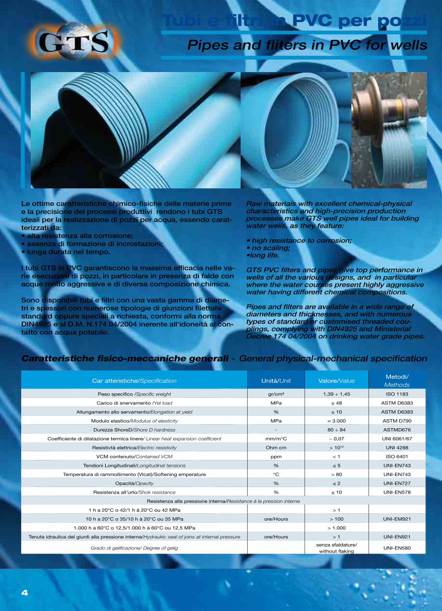
Raw materials with excellent chemical-physical characteristics and high-precision production processes make GTS well pipes ideal for building water wells, as they feature:
• high resistance to corrosion;• no scaling;•long life.
GTS PVC filters and pipes give top performance in wells of all the various designs, and in particular where the water courses present highly aggressive water having different chemical compositions.
Pipes and filters are available in a wide range of diameters and thicknesses, and with numerous types of standard or customised threaded cou-plings, complying with DIN4925 and Ministerial Decree 174 04/2004 on drinking water grade pipes.
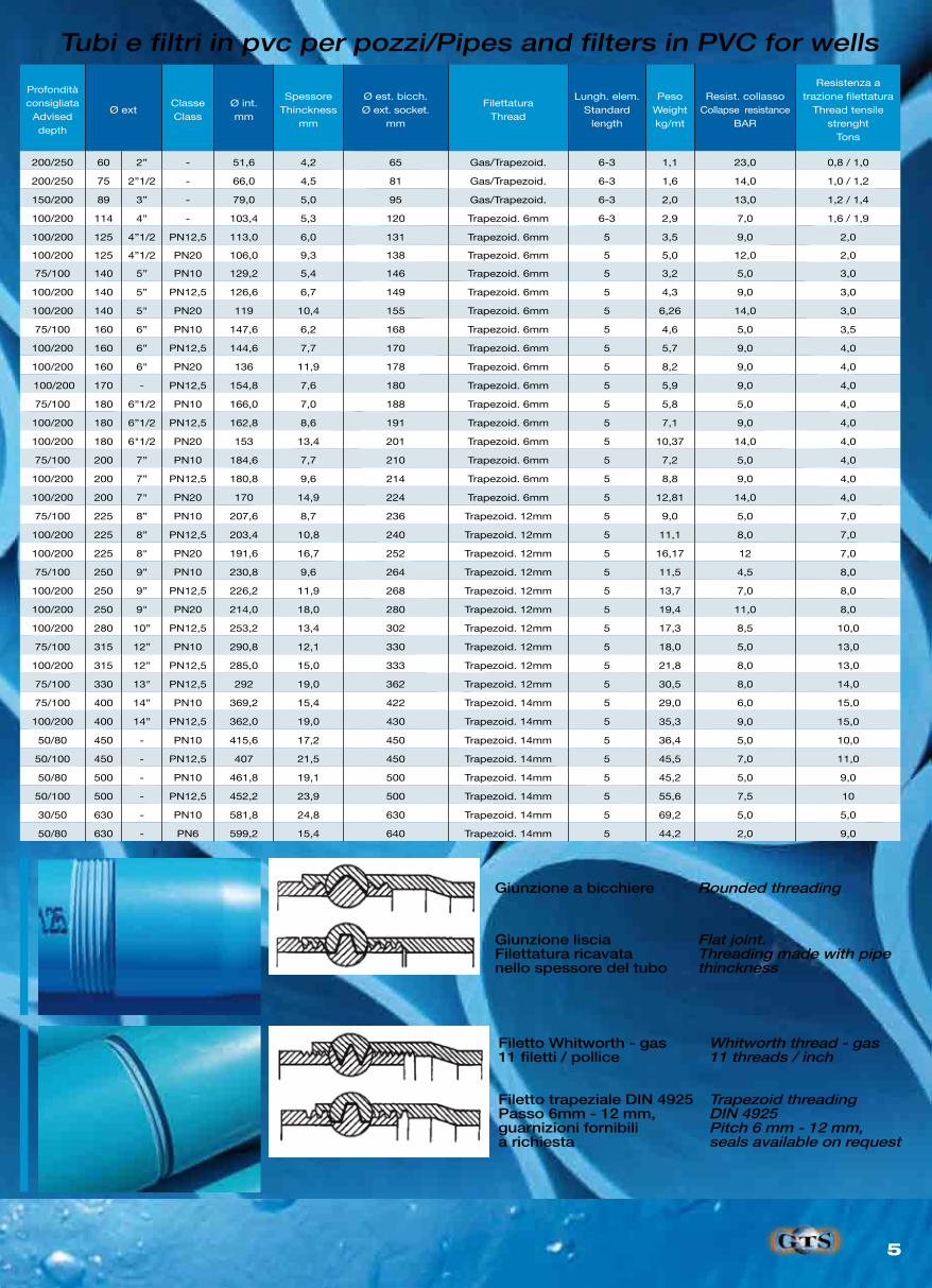
Pipes and fliters in PVC for wells
General physical-mechanical specification
Le ottime caratteristiche chimico-fisiche delle materie prime e la precisione dei processi produttivi rendono i tubi GTS ideali per la realizzazione di pozzi per acqua, essendo carat-terizzati da:• alta resistenza alla corrosione;• assenza di formazione di incrostazioni;• lunga durata nel tempo.
I tubi GTS in PVC garantiscono la massima efficacia nelle va-rie esecuzioni di pozzi, in particolare in presenza di falde con acque molto aggressive e di diversa composizione chimica.
Sono disponibili tubi e filtri con una vasta gamma di diame-tri e spessori con numerose tipologie di giunzioni filettate standard oppure speciali a richiesta, conformi alla norma DIN4925 e al D.M. N.174 04/2004 inerente all'idoneità al con-tatto con acqua potabile.
Caratteristiche fisico-meccaniche generali -
Tubi e filtri in PVC per pozzi
5
Profonditàconsigliata
Adviseddepth
Ø ext ClasseClass
Ø int.mm
SpessoreThinckness
mm
Ø est. bicch.Ø ext. socket.
mm
FilettaturaThread
Lungh. elem.Standard
length
PesoWeightkg/mt
Resist. collassoCollapse resistance
BAR
Resistenza atrazione filettatura
Thread tensilestrenght
Tons
200/250 60 2” - 51,6 4,2 65 Gas/Trapezoid. 6-3 1,1 23,0 0,8 / 1,0
200/250 75 2”1/2 - 66,0 4,5 81 Gas/Trapezoid. 6-3 1,6 14,0 1,0 / 1,2
150/200 89 3” - 79,0 5,0 95 Gas/Trapezoid. 6-3 2,0 13,0 1,2 / 1,4
100/200 114 4” - 103,4 5,3 120 Trapezoid. 6mm 6-3 2,9 7,0 1,6 / 1,9
100/200 125 4”1/2 PN12,5 113,0 6,0 131 Trapezoid. 6mm 5 3,5 9,0 2,0
100/200 125 4”1/2 PN20 106,0 9,3 138 Trapezoid. 6mm 5 5,0 12,0 2,0
75/100 140 5” PN10 129,2 5,4 146 Trapezoid. 6mm 5 3,2 5,0 3,0
100/200 140 5” PN12,5 126,6 6,7 149 Trapezoid. 6mm 5 4,3 9,0 3,0
100/200 140 5" PN20 119 10,4 155 Trapezoid. 6mm 5 6,26 14,0 3,0
75/100 160 6” PN10 147,6 6,2 168 Trapezoid. 6mm 5 4,6 5,0 3,5
100/200 160 6” PN12,5 144,6 7,7 170 Trapezoid. 6mm 5 5,7 9,0 4,0
100/200 160 6" PN20 136 11,9 178 Trapezoid. 6mm 5 8,2 9,0 4,0
100/200 170 - PN12,5 154,8 7,6 180 Trapezoid. 6mm 5 5,9 9,0 4,0
75/100 180 6”1/2 PN10 166,0 7,0 188 Trapezoid. 6mm 5 5,8 5,0 4,0
100/200 180 6”1/2 PN12,5 162,8 8,6 191 Trapezoid. 6mm 5 7,1 9,0 4,0
100/200 180 6"1/2 PN20 153 13,4 201 Trapezoid. 6mm 5 10,37 14,0 4,0
75/100 200 7” PN10 184,6 7,7 210 Trapezoid. 6mm 5 7,2 5,0 4,0
100/200 200 7” PN12,5 180,8 9,6 214 Trapezoid. 6mm 5 8,8 9,0 4,0
100/200 200 7" PN20 170 14,9 224 Trapezoid. 6mm 5 12,81 14,0 4,0
75/100 225 8” PN10 207,6 8,7 236 Trapezoid. 12mm 5 9,0 5,0 7,0
100/200 225 8” PN12,5 203,4 10,8 240 Trapezoid. 12mm 5 11,1 8,0 7,0
100/200 225 8" PN20 191,6 16,7 252 Trapezoid. 12mm 5 16,17 12 7,0
75/100 250 9” PN10 230,8 9,6 264 Trapezoid. 12mm 5 11,5 4,5 8,0
100/200 250 9” PN12,5 226,2 11,9 268 Trapezoid. 12mm 5 13,7 7,0 8,0
100/200 250 9" PN20 214,0 18,0 280 Trapezoid. 12mm 5 19,4 11,0 8,0
100/200 280 10” PN12,5 253,2 13,4 302 Trapezoid. 12mm 5 17,3 8,5 10,0
75/100 315 12” PN10 290,8 12,1 330 Trapezoid. 12mm 5 18,0 5,0 13,0
100/200 315 12” PN12,5 285,0 15,0 333 Trapezoid. 12mm 5 21,8 8,0 13,0
75/100 330 13" PN12,5 292 19,0 362 Trapezoid. 12mm 5 30,5 8,0 14,0
75/100 400 14” PN10 369,2 15,4 422 Trapezoid. 14mm 5 29,0 6,0 15,0
100/200 400 14” PN12,5 362,0 19,0 430 Trapezoid. 14mm 5 35,3 9,0 15,0
50/80 450 - PN10 415,6 17,2 450 Trapezoid. 14mm 5 36,4 5,0 10,0
50/100 450 - PN12,5 407 21,5 450 Trapezoid. 14mm 5 45,5 7,0 11,0
50/80 500 - PN10 461,8 19,1 500 Trapezoid. 14mm 5 45,2 5,0 9,0
50/100 500 - PN12,5 452,2 23,9 500 Trapezoid. 14mm 5 55,6 7,5 10
30/50 630 - PN10 581,8 24,8 630 Trapezoid. 14mm 5 69,2 5,0 5,0
50/80 630 - PN6 599,2 15,4 640 Trapezoid. 14mm 5 44,2 2,0 9,0
Rounded threading
Flat joint.Threading made with pipethinckness
Whitworth thread - gas11 threads / inch
Trapezoid threadingDIN 4925Pitch 6 mm - 12 mm,seals available on request
Pipes and filters in PVC for wells
Giunzione a bicchiere
Giunzione lisciaFilettatura ricavatanello spessore del tubo
Filetto Whitworth - gas11 filetti / pollice
Filetto trapeziale DIN 4925Passo 6mm - 12 mm, guarnizioni fornibilia richiesta
Tubi e filtri in pvc per pozzi/
6
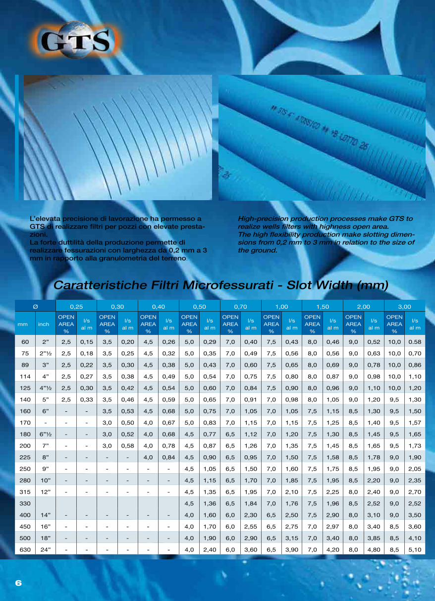
Caratteristiche Filtri Microfessurati - Slot Width (mm)
Ø 0,25 0,30 0,40 0,50 0,70 1,00 1,50 2,00 3,00
mm inchOPEN AREA
%
l/sal m
OPEN AREA
%
l/sal m
OPEN AREA
%
l/sal m
OPEN AREA
%
l/sal m
OPEN AREA
%
l/sal m
OPEN AREA
%
l/sal m
OPEN AREA
%
l/sal m
OPEN AREA
%
l/sal m
OPEN AREA
%
l/sal m
60 2” 2,5 0,15 3,5 0,20 4,5 0,26 5,0 0,29 7,0 0,40 7,5 0,43 8,0 0,46 9,0 0,52 10,0 0.58
75 2”½ 2,5 0,18 3,5 0,25 4,5 0,32 5,0 0,35 7,0 0,49 7,5 0,56 8,0 0,56 9,0 0,63 10,0 0,70
89 3” 2,5 0,22 3,5 0,30 4,5 0,38 5,0 0,43 7,0 0,60 7,5 0,65 8,0 0,69 9,0 0,78 10,0 0,86
114 4” 2,5 0,27 3,5 0,38 4,5 0,49 5,0 0,54 7,0 0,75 7,5 0,80 8,0 0,87 9,0 0,98 10,0 1,10
125 4”½ 2,5 0,30 3,5 0,42 4,5 0,54 5,0 0,60 7,0 0,84 7,5 0,90 8,0 0,96 9,0 1,10 10,0 1,20
140 5” 2,5 0,33 3,5 0,46 4,5 0,59 5,0 0,65 7,0 0,91 7,0 0,98 8,0 1,05 9,0 1,20 9,5 1,30
160 6” - - 3,5 0,53 4,5 0,68 5,0 0,75 7,0 1,05 7,0 1,05 7,5 1,15 8,5 1,30 9,5 1,50
170 - - - 3,0 0,50 4,0 0,67 5,0 0,83 7,0 1,15 7,0 1,15 7,5 1,25 8,5 1,40 9,5 1,57
180 6”½ - - 3,0 0,52 4,0 0,68 4,5 0,77 6,5 1,12 7,0 1,20 7,5 1,30 8,5 1,45 9,5 1,65
200 7” - - 3,0 0,58 4,0 0,78 4,5 0,87 6,5 1,26 7,0 1,35 7,5 1,45 8,5 1,65 9,5 1,73
225 8” - - - - 4,0 0,84 4,5 0,90 6,5 0,95 7,0 1,50 7,5 1,58 8,5 1,78 9,0 1,90
250 9” - - - - - - 4,5 1,05 6,5 1,50 7,0 1,60 7,5 1,75 8,5 1,95 9,0 2,05
280 10” - - - - - - 4,5 1,15 6,5 1,70 7,0 1,85 7,5 1,95 8,5 2,20 9,0 2,35
315 12” - - - - - - 4,5 1,35 6,5 1,95 7,0 2,10 7,5 2,25 8,0 2,40 9,0 2,70
330 4,5 1,36 6,5 1,84 7,0 1,76 7,5 1,96 8,5 2,52 9,0 2,52
400 14” - - - - - - 4,0 1,60 6,0 2,30 6,5 2,50 7,5 2,90 8,0 3,10 9,0 3,50
450 16” - - - - - - 4,0 1,70 6,0 2,55 6,5 2,75 7,0 2,97 8,0 3,40 8,5 3,60
500 18” - - - - - - 4,0 1,90 6,0 2,90 6,5 3,15 7,0 3,40 8,0 3,85 8,5 4,10
630 24” - - - - - - 4,0 2,40 6,0 3,60 6,5 3,90 7,0 4,20 8,0 4,80 8,5 5,10
High-precision production processes make GTS to realize wells filters with highness open area.The high flexibility production make slotting dimen-sions from 0,2 mm to 3 mm in relation to the size of the ground.
L’elevata precisione di lavorazione ha permesso aGTS di realizzare filtri per pozzi con elevate presta-zioni.La forte duttilità della produzione permette direalizzare fessurazioni con larghezza da 0,2 mm a 3 mm in rapporto alla granulometria del terreno.
7
Ø Extmm inch
Ø int.mm
SpessoreThinckness
mm
Ø extMan/Bicch
Sleeve/Socketmm
FilettaturaThread types
Lunghezza elem. standard
Lenght of itemmt
PesoWeightkg/mt
21,1 1/2” 15,9 2,6 26 Gas 0 - 3 0,2
26,5 3/4” 21,3 2,6 30 Gas 0 - 3 0,3
33,3 1” 26,7 3,3 40 Gas 0 - 3 0,5
42,0 1”1/4 34,6 3,7 49 Gas 0 - 3 0,7
48,0 1”1/2 40,0 4,0 55 Gas 0 - 3 0,8
60,0 2” 51,60 4,2 65 Gas/Trapezoid. 6 - 3 1,1
75,0 2”1/2 66,00 2,5 81 Gas/Trapezoid. 6 - 3 1,6
89,0 3” 79,00 5,0 95 Gas/Trapezoid. 6 - 3 2,0
114,0 4” 103,40 5,3 120 Gas/Trapezoid. 6 - 3 2,9
PE100
Ø Ext.PN 10 SDR17
SP (mm)
PN 16SDR11
SP (mm)
PN 25SDR7,4SP (mm)
63 3,8 5,8 8,6
75 4,5 6,8 10,3
90 5,4 8,2 12,3
110 6,6 10,0 15,1
125 7,4 11,4 17,1
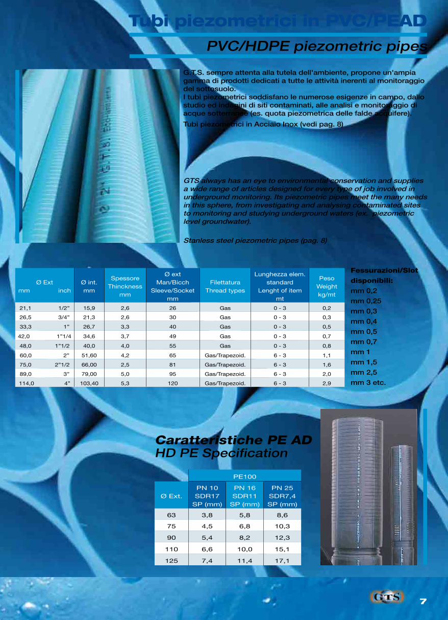
GTS always has an eye to environmental conservation and supplies a wide range of articles designed for every type of job involved in underground monitoring. Its piezometric pipes meet the many needs in this sphere, from investigating and analysing contaminated sites to monitoring and studying underground waters (ex. piezometric level groundwater).
Stanless steel piezometric pipes (pag. 8)
HD PE Specification
G.T.S. sempre attenta alla tutela dell'ambiente, propone un'ampia gamma di prodotti dedicati a tutte le attività inerenti al monitoraggio del sottosuolo.I tubi piezometrici soddisfano le numerose esigenze in campo, dallo studio ed indagini di siti contaminati, alle analisi e monitoraggio di acque sotterranee (es. quota piezometrica delle falde acquifere).
Tubi piezometrici in Acciaio Inox (vedi pag. 8)
Fessurazioni/Slot
disponibili:
mm 0,2
mm 0,25
mm 0,3
mm 0,4
mm 0,5
mm 0,7
mm 1
mm 1,5
mm 2,5
mm 3 etc.
Caratteristiche PE AD
Tubi piezometrici in PVC/PEADPVC/HDPE piezometric pipes
8
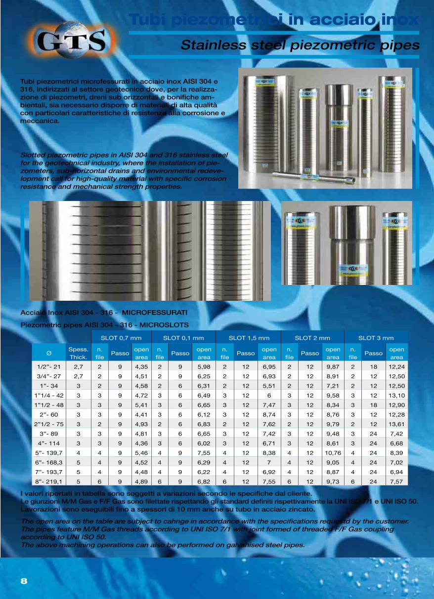
SLOT 0,7 mm SLOT 0,1 mm SLOT 1,5 mm SLOT 2 mm SLOT 3 mm
ØSpess.Thick.
n. file
Passoopenarea
n. file
Passoopenarea
n. file
Passoopenarea
n. file
Passoopenarea
n. file
Passoopenarea
1/2”- 21 2,7 2 9 4,35 2 9 5,98 2 12 6,95 2 12 9,87 2 18 12,24
3/4”- 27 2,7 2 9 4,51 2 9 6,25 2 12 6,93 2 12 8,91 2 12 12,50
1”- 34 3 2 9 4,58 2 6 6,31 2 12 5,51 2 12 7,21 2 12 12,50
1”1/4 - 42 3 3 9 4,72 3 6 6,49 3 12 6 3 12 9,58 3 12 13,10
1”1/2 - 48 3 3 9 5,41 3 6 6,65 3 12 7,47 3 12 8,34 3 18 12,90
2”- 60 3 3 9 4,41 3 6 6,12 3 12 8,74 3 12 8,76 3 12 12,28
2”1/2 - 75 3 2 9 4,93 2 6 6,83 2 12 7,62 2 12 9,79 2 12 13,61
3”- 89 3 3 9 4,81 3 6 6,65 3 12 7,42 3 12 9,48 3 24 7,42
4”- 114 3 3 9 4,36 3 6 6,02 3 12 6,71 3 12 8,61 3 24 6,68
5”- 139,7 4 4 9 5,46 4 9 7,55 4 12 8,38 4 12 10,76 4 24 8,39
6”- 168,3 5 4 9 4,52 4 9 6,29 4 12 7 4 12 9,05 4 24 7,02
7”- 193,7 5 4 9 4,48 4 9 6,22 4 12 6,92 4 12 8,87 4 24 6,94
8”- 219,1 5 6 9 4,89 6 9 6,82 6 12 7,55 6 12 9,73 6 24 7,57
The open area on the table are subject to cahnge in accordance with the specifications requestd by the customer.The pipes feature M/M Gas threads according to UNI ISO 7/1 with joint formed of threaded F/F Gas couplingaccording to UNI ISO 50.The above machining operations can also be performed on galvanised steel pipes.
Slotted piezometric pipes in AISI 304 and 316 stainless steel for the geotechnical industry, where the installation of pie-zometers, sub-horizontal drains and environmental redeve-lopment call for high-quality material with specific corrosion resistance and mechanical strength properties.
Stainless steel piezometric pipes
Piezometric pipes AISI 304 - 316 - MICROSLOTS
Acciaio Inox AISI 304 - 316 - MICROFESSURATI
I valori riportati in tabella sono soggetti a variazioni secondo le specifiche dal cliente.Le giunzioni M/M Gas e F/F Gas sono filettate rispettando gli standard definiti rispettivamente la UNI ISO 7/1 e UNI ISO 50.Lavorazioni sono eseguibili fino a spessori di 10 mm anche su tubo in acciaio zincato.
Tubi piezometrici microfessurati in acciaio inox AISI 304 e 316, indirizzati al settore geotecnico dove, per la realizza-zione di piezometri, dreni sub orizzontali e bonifiche am-bientali, sia necessario disporre di materiali di alta qualità con particolari caratteristiche di resistenza alla corrosione e meccanica.
Tubi piezometrici in acciaio inox
9
Principali caratteristiche tubo polietilene/Main specifications of polyethilene pipes
Descrizione/Description Unità/Unit PE80 PE100Metodo di prova
Test method
Densità/Density g/cm³ 0,945 - 0,957 0,955 - 0,961 ISO 1183
Indice di fluidità (190°C, 5,0 Kg)/Melt index g/10 min 0,4 - 0,6 0,2 - 0,5 ISO 1133
Carico di snervamento/Yield point N/mm² circa/about 22 circa/about 24 ISO 6259
Allungamento a rottura/Ultimate elongation % > 600 > 600 ISO 6259
Durezza (20°C) Hardness shore D 57 59 ISO 868
Coefficente di dilatazione linere (20-90°C)Linear expansion coefficient (20-90°C)
mm/m°C 0,13 0,13 ISO 11359
Conducibilità termica 20°)/Heat stability at 200°C W/m*k 0,4 0,4 DIN52612
Stabilità termica a 200°C (OIT)/Heat stability at 200°C
min > 15 >15 UNI EN 728
Temperatura di fragilità/brittle temperature °C <-100 <-70 ASTM D 746
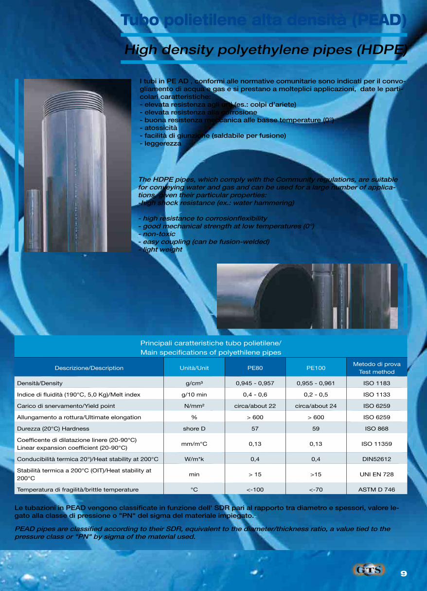
The HDPE pipes, which comply with the Community regulations, are suitable for conveying water and gas and can be used for a large number of applica-tions, given their particular properties:-high shock resistance (ex.: water hammering)
- high resistance to corrosionflexibility- good mechanical strength at low temperatures (0°)- non-toxic- easy coupling (can be fusion-welded)- light weight
PEAD pipes are classified according to their SDR, equivalent to the diameter/thickness ratio, a value tied to the pressure class or "PN" by sigma of the material used.
High density polyethylene pipes (HDPE)
I tubi in PE AD , conformi alle normative comunitarie sono indicati per il convo-gliamento di acqua e gas e si prestano a molteplici applicazioni, date le parti-colari caratteristiche:- elevata resistenza agli urti (es.: colpi d’ariete)- elevata resistenza alla corrosione- buona resistenza meccanica alle basse temperature (0°)- atossicità- facilità di giunzione (saldabile per fusione)- leggerezza
Le tubazioni in PEAD vengono classificate in funzione dell' SDR pari al rapporto tra diametro e spessori, valore le-gato alla classe di pressione o "PN" del sigma del materiale impiegato.
Tubo polietilene alta densità (PEAD)
10
PE80 serie GAS PE100
DN
S8 MOP3 BAR
SDR17,6SP (mm)
S5 MOP5 BAR
SP (mm)
PN 6SDR26
SP (mm)
PN 10SDR17
SP (mm)
PN 16SDR11
SP (mm)
PN 25SDR7,4SP (mm)
63 3,6 5,8 - 3,8 5,8 8,6
75 4,3 6,8 - 4,5 6,8 10,3
90 5,2 8,2 - 5,4 8,2 12,3
110 6,3 10,0 - 6,6 10,0 15,1
125 7,1 11,4 - 7,4 11,4 17,1
140 8,0 12,7 - 8,3 12,7 192
160 9,1 14,6 6,2 9,5 14,6 21,9
180 10,3 16,4 6,9 10,7 16,4 24,6
200 11,4 18,2 7,7 11,9 18,2 27,4
225 12,8 20,5 8,6 13,4 20,5 30,8
250 14,2 22,7 9,6 14,8 22,7 34,2
280 16,0 25,4 10,7 16,6 25,4 38,3
315 17,9 28,6 12,1 18,7 28,6 43,1
355 20,5 32,2 13,6 21,1 32,2 48,5
400 22,8 36,3 15,3 23,7 36,3 54,7
450 - - 17,2 26,7 40,9 61,5
500 - - 19,1 29,7 45,4 -
500 - - 21,4 33,2 50,8 -
630 - - 24,1 37,4 57,2 -
710 - - 27,2 42,1 - -
800 - - 30,6 47,4 - -
900 - - 34,4 53,3 - -
1.000 - - 8,2 59,3 - -
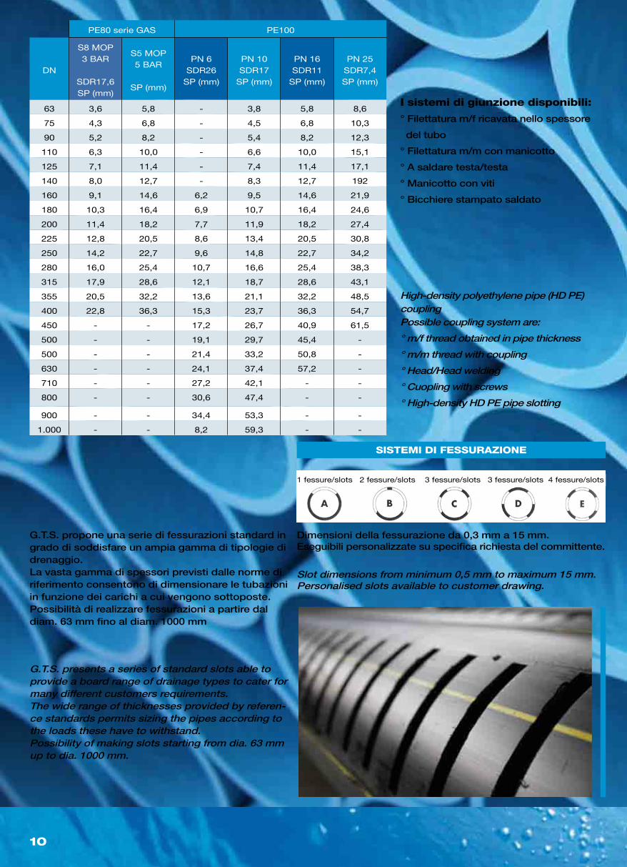
G.T.S. presents a series of standard slots able to provide a board range of drainage types to cater for many different customers requirements.The wide range of thicknesses provided by referen-ce standards permits sizing the pipes according to the loads these have to withstand. Possibility of making slots starting from dia. 63 mm up to dia. 1000 mm.
Slot dimensions from minimum 0,5 mm to maximum 15 mm.Personalised slots available to customer drawing.
High-density polyethylene pipe (HD PE) couplingPossible coupling system are:
° m/f thread obtained in pipe thickness
° m/m thread with coupling
° Head/Head welding
° Cuopling with screws
° High-density HD PE pipe slotting
I sistemi di giunzione disponibili:
° Filettatura m/f ricavata nello spessore
del tubo
° Filettatura m/m con manicotto
° A saldare testa/testa
° Manicotto con viti
° Bicchiere stampato saldato
G.T.S. propone una serie di fessurazioni standard in grado di soddisfare un ampia gamma di tipologie di drenaggio.La vasta gamma di spessori previsti dalle norme di riferimento consentono di dimensionare le tubazioni in funzione dei carichi a cui vengono sottoposte.Possibilità di realizzare fessurazioni a partire dal diam. 63 mm fino al diam. 1000 mm
Dimensioni della fessurazione da 0,3 mm a 15 mm.Eseguibili personalizzate su specifica richiesta del committente.
1 fessure/slots 2 fessure/slots 3 fessure/slots 3 fessure/slots 4 fessure/slots
11
Ø ext.Ø int.
tubo/pipe mmFilettaturathreading
Lunghezza elementiLenght of sections m
60 32 trapezoidal 3
75 32 - 42 trapezoidal 3
89 48 - 60 trapezoidal 3
114 60 - 75 trapezoidal 3
125 75 - 89 trapezoidal 3
Ø ext.SpessoreThickness
Ø int.Ing. max.
Bicch./Man.Sleeve/Socket
FilettaturaThread types
mm inch mm mm mm
33,3 1" 3,3 26,7 40 Gas
42,0 1"1/4 3,7 34,6 49 Gas
48,0 1"1/2 4,0 40,0 55 Gas
60 2" 4,0 52 65 Gas/Trapeziod.
75 2"1/2 4,3 66,4 81 Gas/Trapeziod.
89 3" 4,5 80,0 94 Gas/Trapeziod.
114 4" 5,0 104,0 120 Gas/Trapeziod.
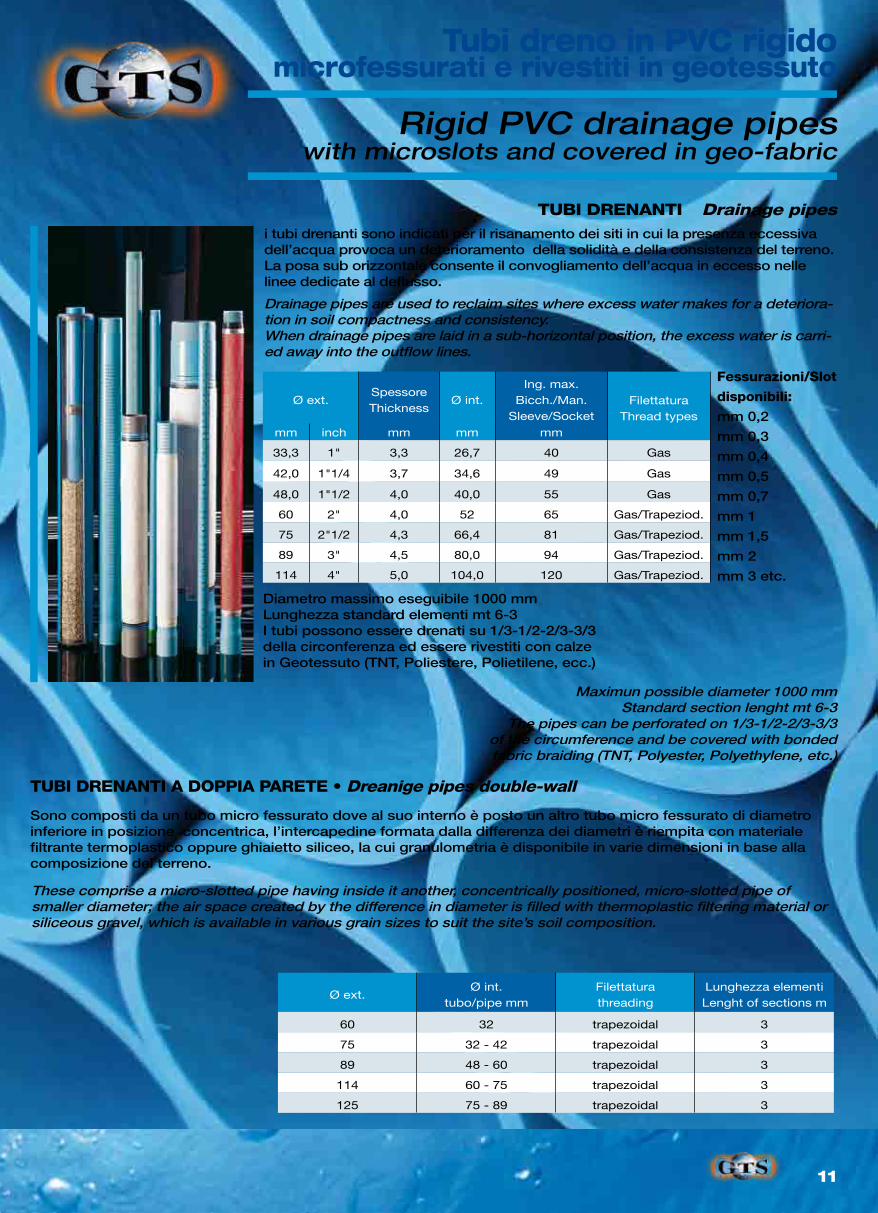
These comprise a micro-slotted pipe having inside it another, concentrically positioned, micro-slotted pipe of smaller diameter; the air space created by the difference in diameter is filled with thermoplastic filtering material or siliceous gravel, which is available in various grain sizes to suit the site’s soil composition.
Maximun possible diameter 1000 mmStandard section lenght mt 6-3
The pipes can be perforated on 1/3-1/2-2/3-3/3of the circumference and be covered with bondedfabric braiding (TNT, Polyester, Polyethylene, etc.)
Drainage pipes are used to reclaim sites where excess water makes for a deteriora-tion in soil compactness and consistency. When drainage pipes are laid in a sub-horizontal position, the excess water is carri-ed away into the outflow lines.
Rigid PVC drainage pipeswith microslots and covered in geo-fabric
Drainage pipes
Dreanige pipes double-wall
i tubi drenanti sono indicati per il risanamento dei siti in cui la presenza eccessiva dell’acqua provoca un deterioramento della solidità e della consistenza del terreno. La posa sub orizzontale consente il convogliamento dell’acqua in eccesso nelle linee dedicate al deflusso.
Sono composti da un tubo micro fessurato dove al suo interno è posto un altro tubo micro fessurato di diametro inferiore in posizione concentrica, l’intercapedine formata dalla differenza dei diametri è riempita con materiale filtrante termoplastico oppure ghiaietto siliceo, la cui granulometria è disponibile in varie dimensioni in base alla composizione del terreno.
Diametro massimo eseguibile 1000 mmLunghezza standard elementi mt 6-3I tubi possono essere drenati su 1/3-1/2-2/3-3/3della circonferenza ed essere rivestiti con calzein Geotessuto (TNT, Poliestere, Polietilene, ecc.)
TUBI DRENANTI A DOPPIA PARETE •
Fessurazioni/Slot
disponibili:
mm 0,2
mm 0,3
mm 0,4
mm 0,5
mm 0,7
mm 1
mm 1,5
mm 2
mm 3 etc.
TUBI DRENANTI
Tubi dreno in PVC rigidomicrofessurati e rivestiti in geotessuto
12
Serie NormaleStandard series
Serie RinforzataReinforced series
Diametro EsternoExternal diameter
mm 34 38 40 48 48 60 38 40 48
Diametro InternoInternal diameter
mm 27 32 34 42 40 52 27 31 34
Diametro Est. manicottoExt. coupling diameter
mm 40 44 49 55 55 68 40 49 55
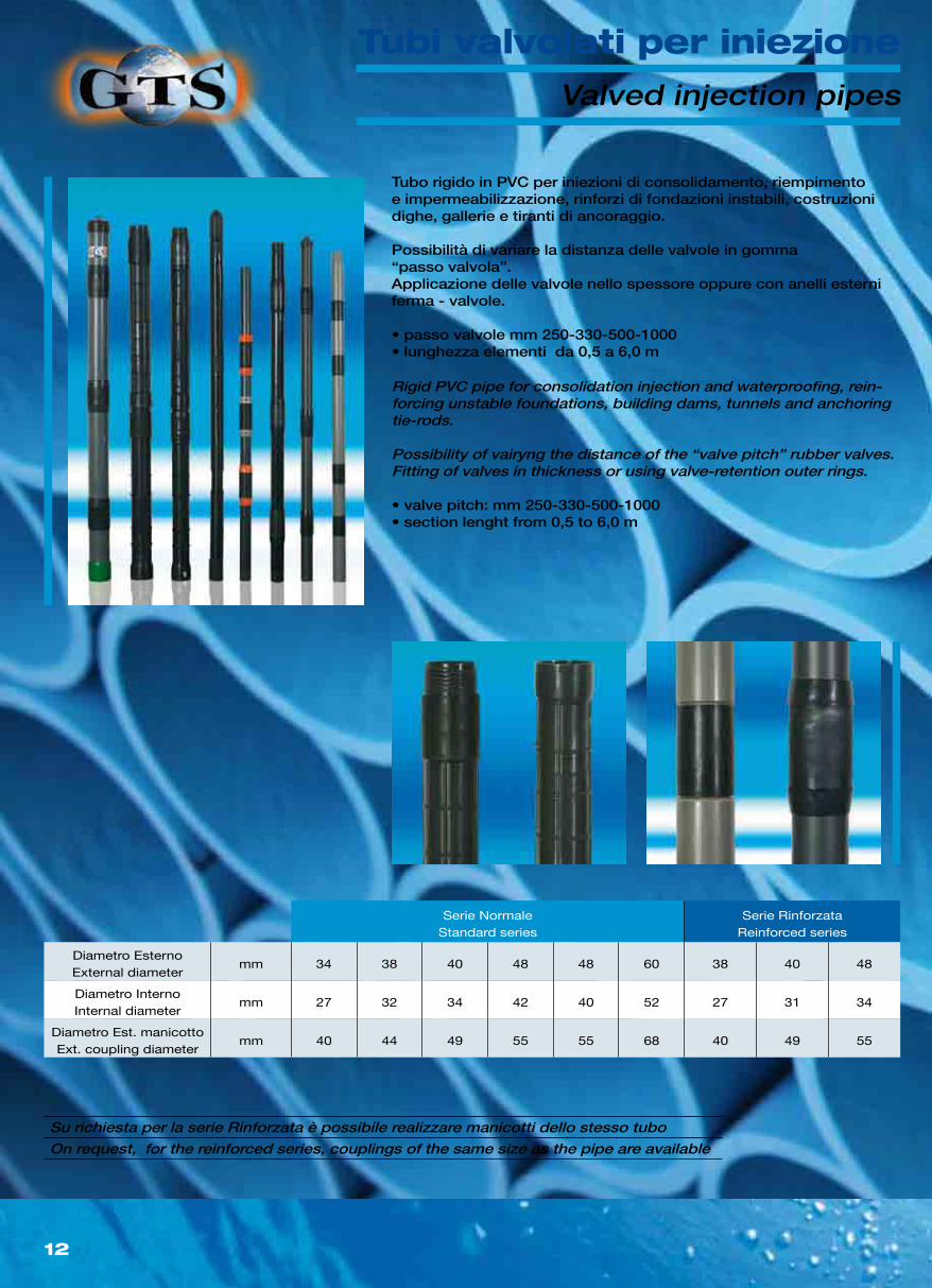
Rigid PVC pipe for consolidation injection and waterproofing, rein-forcing unstable foundations, building dams, tunnels and anchoring tie-rods.
Possibility of vairyng the distance of the “valve pitch” rubber valves.Fitting of valves in thickness or using valve-retention outer rings.
• valve pitch: mm 250-330-500-1000• section lenght from 0,5 to 6,0 m
Valved injection pipes
On request, for the reinforced series, couplings of the same size as the pipe are available
Tubo rigido in PVC per iniezioni di consolidamento, riempimento e impermeabilizzazione, rinforzi di fondazioni instabili, costruzioni dighe, gallerie e tiranti di ancoraggio.
Possibilità di variare la distanza delle valvole in gomma“passo valvola”.Applicazione delle valvole nello spessore oppure con anelli esterni ferma - valvole.
• passo valvole mm 250-330-500-1000• lunghezza elementi da 0,5 a 6,0 m
Su richiesta per la serie Rinforzata è possibile realizzare manicotti dello stesso tubo
Tubi valvolati per iniezione
13
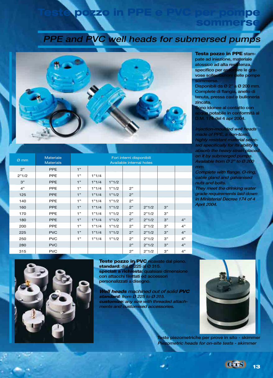
Ø mmMaterialeMaterials
Fori interni disponibiliAvailable internal holes
2” PPE 1”
2”1/2 PPE 1” 1”1/4
3” PPE 1” 1”1/4 1”1/2
4” PPE 1” 1”1/4 1”1/2 2”
125 PPE 1” 1”1/4 1”1/2 2”
140 PPE 1” 1”1/4 1”1/2 2”
160 PPE 1” 1”1/4 1”1/2 2” 2”1/2 3”
170 PPE 1” 1”1/4 1”1/2 2” 2”1/2 3”
180 PPE 1” 1”1/4 1”1/2 2” 2”1/2 3” 4”
200 PPE 1” 1”1/4 1”1/2 2” 2”1/2 3” 4”
225 PVC 1” 1”1/4 1”1/2 2” 2”1/2 3” 4”
250 PVC 1” 1”1/4 1”1/2 2” 2”1/2 3” 4”
280 PVC 2” 2”1/2 3” 4”
315 PVC 2” 2”1/2 3” 4”
Piezometric heads for on-site tests - skimmer
Injection-moulded well heads made of PPE, a non-toxic, highly resistant material selec-ted specifically for its ability to absorb the heavy strain placed on it by submerged pumps.Available from Ø 2” to Ø 200 mm.Complete with flange, O-ring, cable gland and galvanised nuts and bolts.They meet the drinking water grade requirements laid down in Ministerial Decree 174 of 4 April 2004.
Well heads machined out of solid PVCstandard: from Ø 225 to Ø 315.customize: any size with threaded attach-ments and customised accessories.
PPE and PVC well heads for submersed pumps
Teste piezometriche per prove in sito - skimmer
Testa pozzo in PPE stam-pate ad iniezione, materiale atossico ad alta resistenza, specifico per assorbire le gra-vose sollecitazioni delle pompe sommerse.Disponibili da Ø 2” a Ø 200 mm.Complete di flangia, anello di tenuta, pressa cavi e bulloneria zincata.Sono idonee al contatto con acqua potabile in conformità al D.M. 174 del 4 apr 2004.
Teste pozzo in PVC ricavate dal pieno. standard: dal Ø 225 al Ø 315.speciali a richiesta: qualsiasi dimensione con attacchi filettati ed accessoripersonalizzati a disegno.
Teste pozzo in PPE e PVC per pompe sommerse
14
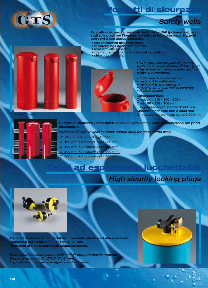
• high resistance to corrosion• resistant to salt spray• resistant to the elements• roughened to hold well in concrete• reinforced seal
Padlockable safety wells in epoxy coated steel for piezometric wells
Hight sicurity locking caps made in high-strength plastic material.Diameter available 2”, 2”1/2, 3”, 4” mm.High resistant to corrosive agents and salt water.
HDPE and PA6 (polyamide) safety wells have been developed for use at sites where corrosive agents and salt water are prevalent.
Safety wells
High sicurity locking plugs
Pozzetti di sicurezza realizzati in PE AD e PA6 (poliammide), sono stati sviluppati per l’impiego nei siti con forte presenza di agenti corrosivi e con acqua salmastra.
Tappi ed espansione lucchettabili in materiale plastica ad alta resistenza.Disponibili per i diametri 2”, 2”1/2, 3”, 4” mm.Resistenti alla corrosione e all'acqua salmastra.
• alta resistenza alla corrosione• resistenti agli agenti atmosferici• resistenti alla salsedine• zigrinatura per una forte presa nel calcestruzzo• chiusura rinforzata.
Pozzetti di sicurezza lucchettabili in acciaio verniciato a polveri epossidiche per pozzi piezometrici
Dimensioni/Size:Ø est/ext : 110 - 140 - 200 mmØ int : 98 - 128 - 188 mmLunghezza/lenght standard 500 mmSpeciale a richiesta fino a 3000 mmOn request, customised up to 3,000mm
Ø 80 mm • Altezza/Height 500 mm
Ø 100 mm • Altezza/Height 500 mm
Ø 140 mm • Altezza/Height 500 mm
Ø 200 mm • Altezza/Height 500 mm
Ø 200 mm • Altezza/Height 700 mm
REGISTRED DESIGN N°
Pozzetti di sicurezza
Tappi ad espansione lucchettabili
15
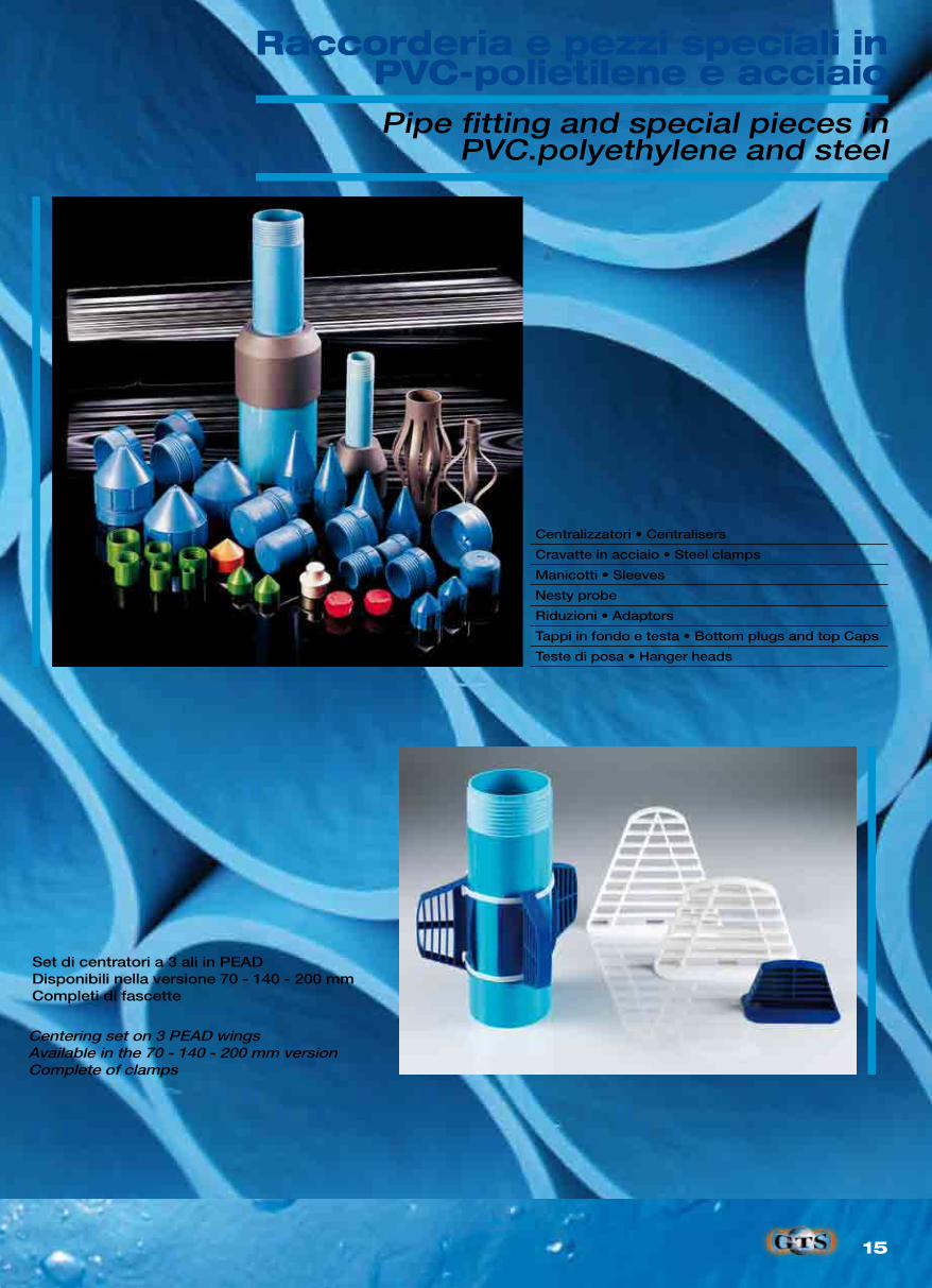
Centralizzatori • Centralisers
Cravatte in acciaio • Steel clamps
Manicotti • Sleeves
Nesty probe
Riduzioni • Adaptors
Tappi in fondo e testa • Bottom plugs and top Caps
Teste di posa • Hanger heads
Centering set on 3 PEAD wingsAvailable in the 70 - 140 - 200 mm versionComplete of clamps
Pipe fitting and special pieces inPVC.polyethylene and steel
Set di centratori a 3 ali in PEADDisponibili nella versione 70 - 140 - 200 mmCompleti di fascette
Raccorderia e pezzi speciali inPVC-polietilene e acciaio
16
Ø ext. Ø int.Ø ext. guide
Ø int. guide
SpessoreLunghezza
barrePeso
Thickness Length Weight
mm mm mm mm mm mm gr/m
53 49 58 54 2 3000 916
manicottocoupling
57,6 54 62,6 59,2 1,7 300 851
80 76 87 83 2 3000 1496
manicottocoupling
85 80,5 92 85 2,25 300 1620
Accessori: Tappi di Fondo, Tappi di Testa, Tappi di sicurezza
60 mm 70 mm 85 mm
mm Casing/size Coupling/size Casing/size Coupling/size Casing/size Coupling/size
A Inner Dia. 50 mm 57 mm 60 mm 67 mm 72,50 mm 83 mm
B Out Dia. 60 mm 67 mm 70 mm 77 mm 85 mm 91,50 mm
C Thickness 3,5 mm 5 mm 3,5 mm 5 mm 4 mm 4,3 mm
D Groove Inner Dia. 53 mm 61,5 mm 63 mm 71,5 mm 76 mm 85,50 mm
Spiral < 0,3° - < 0,3° - < 0,3° -
Lenght 3 M 200 mm 3 M200 mm400 mm
3 M 200 mm
Tolleranza: spirale di 3 metri inferiore ai 0,3° • Spiral of 3 metr less than 0,3°
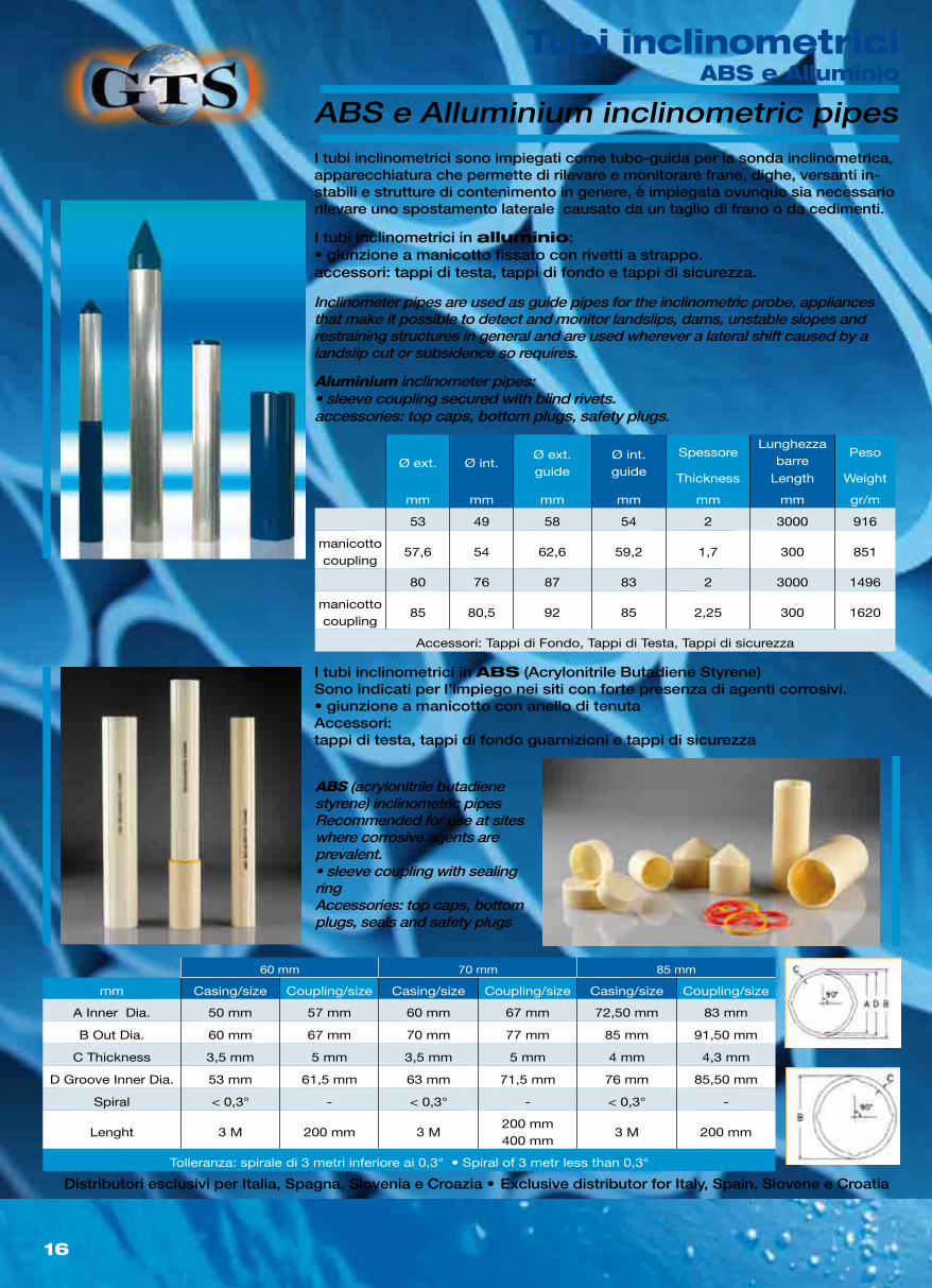
Aluminium inclinometer pipes:• sleeve coupling secured with blind rivets.accessories: top caps, bottom plugs, safety plugs.
Inclinometer pipes are used as guide pipes for the inclinometric probe, appliances that make it possible to detect and monitor landslips, dams, unstable slopes and restraining structures in general and are used wherever a lateral shift caused by a landslip cut or subsidence so requires.
ABS (acrylonitrile butadiene styrene) inclinometric pipesRecommended for use at sites where corrosive agents are prevalent.• sleeve coupling with sealing ringAccessories: top caps, bottom plugs, seals and safety plugs
ABS e Alluminium inclinometric pipes
Exclusive distributor for Italy, Spain, Slovene e Croatia
I tubi inclinometrici in alluminio:• giunzione a manicotto fissato con rivetti a strappo.accessori: tappi di testa, tappi di fondo e tappi di sicurezza.
Distributori esclusivi per Italia, Spagna, Slovenia e Croazia •
I tubi inclinometrici sono impiegati come tubo-guida per la sonda inclinometrica, apparecchiatura che permette di rilevare e monitorare frane, dighe, versanti in-stabili e strutture di contenimento in genere, è impiegata ovunque sia necessario rilevare uno spostamento laterale causato da un taglio di frano o da cedimenti.
I tubi inclinometrici in ABS (Acrylonitrile Butadiene Styrene) Sono indicati per l’impiego nei siti con forte presenza di agenti corrosivi.• giunzione a manicotto con anello di tenutaAccessori:tappi di testa, tappi di fondo guarnizioni e tappi di sicurezza
Tubi inclinometriciABS e Alluminio
17
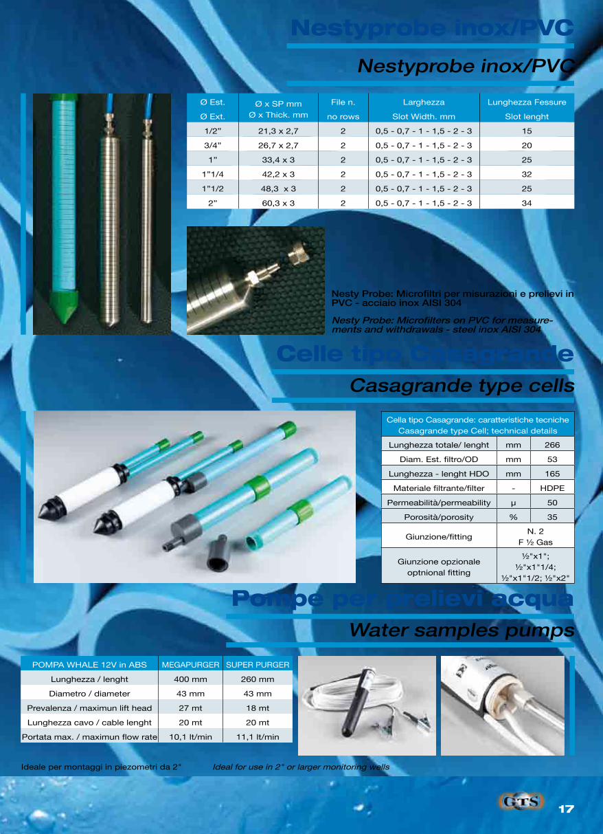
Ø Est. Ø x SP mmØ x Thick. mm
File n. Larghezza Lunghezza Fessure
Ø Ext. no rows Slot Width. mm Slot lenght
1/2” 21,3 x 2,7 2 0,5 - 0,7 - 1 - 1,5 - 2 - 3 15
3/4” 26,7 x 2,7 2 0,5 - 0,7 - 1 - 1,5 - 2 - 3 20
1” 33,4 x 3 2 0,5 - 0,7 - 1 - 1,5 - 2 - 3 25
1”1/4 42,2 x 3 2 0,5 - 0,7 - 1 - 1,5 - 2 - 3 32
1”1/2 48,3 x 3 2 0,5 - 0,7 - 1 - 1,5 - 2 - 3 25
2” 60,3 x 3 2 0,5 - 0,7 - 1 - 1,5 - 2 - 3 34
Cella tipo Casagrande: caratteristiche tecnicheCasagrande type Cell; technical details
Lunghezza totale/ lenght mm 266
Diam. Est. filtro/OD mm 53
Lunghezza - lenght HDO mm 165
Materiale filtrante/filter - HDPE
Permeabilità/permeability µ 50
Porosità/porosity % 35
Giunzione/fittingN. 2
F ½ Gas
Giunzione opzionaleoptnional fitting
½"x1"; ½"x1"1/4;
½"x1"1/2; ½"x2"
POMPA WHALE 12V in ABS MEGAPURGER SUPER PURGER
Lunghezza / lenght 400 mm 260 mm
Diametro / diameter 43 mm 43 mm
Prevalenza / maximun lift head 27 mt 18 mt
Lunghezza cavo / cable lenght 20 mt 20 mt
Portata max. / maximun flow rate 10,1 lt/min 11,1 lt/min
Nesty Probe: Microfilters on PVC for measure-ments and withdrawals - steel inox AISI 304
Ideal for use in 2" or larger monitoring wells
Nestyprobe inox/PVC
Casagrande type cells
Water samples pumps
Nesty Probe: Microfiltri per misurazioni e prelievi in PVC - acciaio inox AISI 304
Ideale per montaggi in piezometri da 2"
Nestyprobe inox/PVC
Celle tipo Casagrande
Pompe per prelievi acqua
18
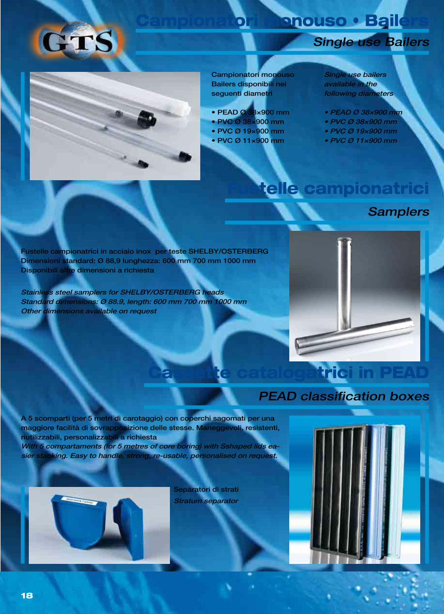
Single use bailersavailable in thefollowing diameters
• PEAD Ø 38×900 mm• PVC Ø 38×900 mm• PVC Ø 19×900 mm• PVC Ø 11×900 mm
With 5 compartaments (for 5 metres of core boring) with Sshaped lids ea-sier stacking. Easy to handle, strong, re-usable, personalised on request.
Stainless steel samplers for SHELBY/OSTERBERG headsStandard dimensions: Ø 88.9, length: 600 mm 700 mm 1000 mmOther dimensions available on request
Stratum separator
Single use Bailers
PEAD classification boxes
Samplers
Campionatori monousoBailers disponibili neiseguenti diametri
• PEAD Ø 38×900 mm• PVC Ø 38×900 mm• PVC Ø 19×900 mm• PVC Ø 11×900 mm
A 5 scomparti (per 5 metri di carotaggio) con coperchi sagomati per una maggiore facilità di sovrapposizione delle stesse. Maneggevoli, resistenti, riutilizzabili, personalizzabili a richiesta
Fustelle campionatrici in acciaio inox per teste SHELBY/OSTERBERGDimensioni standard: Ø 88,9 lunghezza: 600 mm 700 mm 1000 mmDisponibili altre dimensioni a richiesta
Separatori di strati
Campionatori monouso • Bailers
Cassette catalogatrici in PEAD
Fustelle campionatrici
19
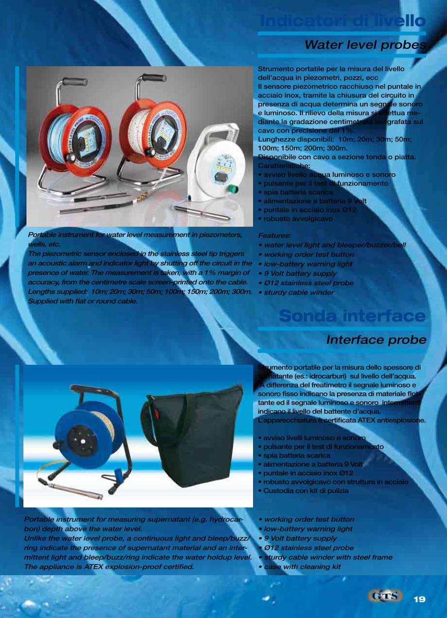
Portable instrument for water level measurement in piezometers, wells, etc.The piezometric sensor enclosed in the stainless steel tip triggers an acoustic alarm and indicator light by shutting off the circuit in the presence of water. The measurement is taken, with a 1% margin of accuracy, from the centimetre scale screen-printed onto the cable.Lengths supplied: 10m; 20m; 30m; 50m; 100m; 150m; 200m; 300m. Supplied with flat or round cable.
Portable instrument for measuring supernatant (e.g. hydrocar-bon) depth above the water level.Unlike the water level probe, a continuous light and bleep/buzz/ring indicate the presence of supernatant material and an inter-mittent light and bleep/buzz/ring indicate the water holdup level.The appliance is ATEX explosion-proof certified.
• working order test button• low-battery warning light• 9 Volt battery supply• Ø12 stainless steel probe• sturdy cable winder with steel frame• case with cleaning kit
Features:• water level light and bleeper/buzzer/bell• working order test button• low-battery warning light• 9 Volt battery supply• Ø12 stainless steel probe• sturdy cable winder
Water level probes
Interface probe
Strumento portatile per la misura del livello dell’acqua in piezometri, pozzi, eccIl sensore piezometrico racchiuso nel puntale in acciaio inox, tramite la chiusura del circuito in presenza di acqua determina un segnale sonoro e luminoso. Il rilievo della misura si effettua me-diante la gradazione centimetrata serigrafata sul cavo con precisione del 1%.Lunghezze disponibili: 10m; 20m; 30m; 50m; 100m; 150m; 200m; 300m. Disponibile con cavo a sezione tonda o piatta.Caratteristiche:• avviso livello acqua luminoso e sonoro• pulsante per il test di funzionamento• spia batteria scarica• alimentazione a batteria 9 Volt• puntale in acciaio inox Ø12• robusto avvolgicavo
Strumento portatile per la misura dello spessore di surnatante (es.: idrocarburi) sul livello dell’acqua. A differenza del freatimetro il segnale luminoso e sonoro fisso indicano la presenza di materiale flot-tante ed il segnale luminoso e sonoro intermittenti indicano il livello del battente d’acqua.L’apparecchiatura è certificata ATEX antiesplosione.
• avviso livelli luminoso e sonoro• pulsante per il test di funzionamento• spia batteria scarica• alimentazione a batteria 9 Volt• puntale in acciaio inox Ø12• robusto avvolgicavo con struttura in acciaio• Custodia con kit di pulizia
Indicatori di livello
Sonda interface
20
Ø mm Spessore mm Lunghezza mt. Diam. Flange mm N. Fori mm Resistenza Trazione kg
Thickness mm Lenght m. Flange diameter mm Number of holes mm Traction strenght kg
50 5,6 5 85 4 900
63 7,1 5 98 6 1.200
75 10,3 5 12 8 1.800
90 12,3 5 150 8 2.400
110 15,1 5 170 8 3.000
Customize pump and well head attachments on request
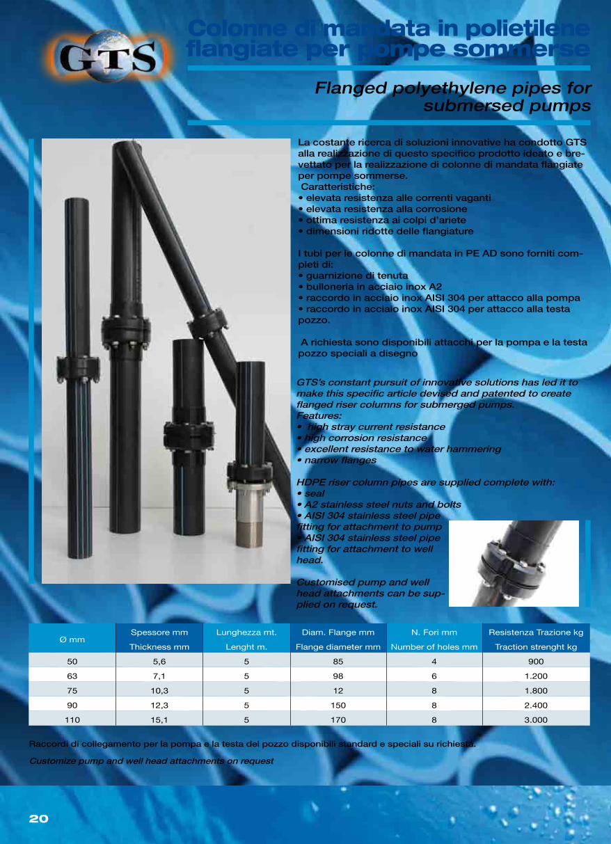
GTS’s constant pursuit of innovative solutions has led it to make this specific article devised and patented to create flanged riser columns for submerged pumps.Features:• high stray current resistance• high corrosion resistance• excellent resistance to water hammering• narrow flanges
HDPE riser column pipes are supplied complete with:• seal• A2 stainless steel nuts and bolts• AISI 304 stainless steel pipe fitting for attachment to pump• AISI 304 stainless steel pipe fitting for attachment to well head.
Customised pump and well head attachments can be sup-plied on request.
Flanged polyethylene pipes forsubmersed pumps
Raccordi di collegamento per la pompa e la testa del pozzo disponibili standard e speciali su richiesta.
La costante ricerca di soluzioni innovative ha condotto GTS alla realizzazione di questo specifico prodotto ideato e bre-vettato per la realizzazione di colonne di mandata flangiate per pompe sommerse. Caratteristiche:• elevata resistenza alle correnti vaganti• elevata resistenza alla corrosione• ottima resistenza ai colpi d’ariete• dimensioni ridotte delle flangiature
I tubi per le colonne di mandata in PE AD sono forniti com-pleti di:• guarnizione di tenuta• bulloneria in acciaio inox A2• raccordo in acciaio inox AISI 304 per attacco alla pompa• raccordo in acciaio inox AISI 304 per attacco alla testa pozzo.
A richiesta sono disponibili attacchi per la pompa e la testa pozzo speciali a disegno
Colonne di mandata in polietileneflangiate per pompe sommerse
21
DNØ Est. TuboØ Ext Pipe
mm
Ø Est. FlangiaØ Ext Flange
mm
Lunghezza BarreLenght Bars
mm
Resistenza TrazioneTensile Strenght
tons
40 48,3 140 3 - 6 -
50 60,3 150 3 - 6 27,2
65 76 165 3 - 6 27,2
80 88,9 185 3 - 6 27,2
100 114,3 200 3 - 6 36,0
125 139,7 220 3 - 6 36,0
150 168,3 250 3 - 6 45,0
200 219,1 315 3 - 6 72,0
DNØ Est TuboØ Ext Pipe
mm
Ø Est GiuntoØ Ext Coupling
mm
Lunghezza BarreLenght Bar
mt
Resistenza TrazioneTensile Strenght
tons
50 60,3 85 3 - 6 22
65 76 106 3 - 6 26
80 88,9 118 3 - 6 29
100 114,3 140 3 - 6 30
125 139,7 170 3 - 6 32
150 168,3 200 3 - 6 32
200 219,1 253 3 - 6 33
DNØ Est. TuboØ Ext Pipe
mm
Ø Est. ManicottoØ Ext Slevee
mm
Lunghezza BarreLenght Bars
mm
Resistenza TrazioneTensile Strenght
tons
40 48,3 62 3 - 6 -
50 60,3 73 3 - 6 13,0
65 76 88,5 3 - 6 13,0
80 88,69 104 3 - 6 13,0
100 114,3 129 3 - 6 18,0
Flange fixed to pipe by twin welded process (internal and external)
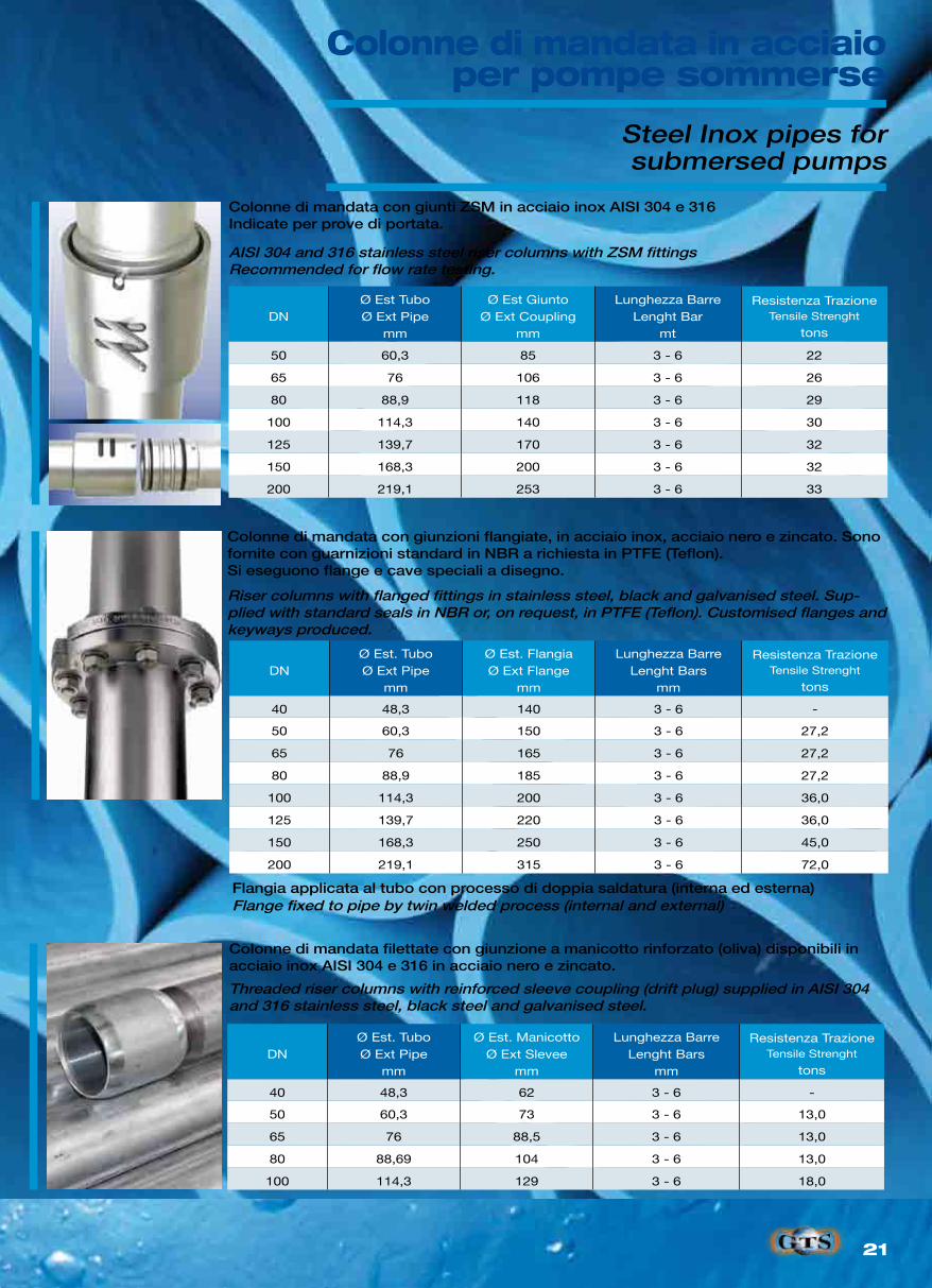
AISI 304 and 316 stainless steel riser columns with ZSM fittingsRecommended for flow rate testing.
Riser columns with flanged fittings in stainless steel, black and galvanised steel. Sup-plied with standard seals in NBR or, on request, in PTFE (Teflon). Customised flanges and keyways produced.
Threaded riser columns with reinforced sleeve coupling (drift plug) supplied in AISI 304 and 316 stainless steel, black steel and galvanised steel.
Steel Inox pipes forsubmersed pumps
Colonne di mandata con giunzioni flangiate, in acciaio inox, acciaio nero e zincato. Sono fornite con guarnizioni standard in NBR a richiesta in PTFE (Teflon).Si eseguono flange e cave speciali a disegno.
Flangia applicata al tubo con processo di doppia saldatura (interna ed esterna)
Colonne di mandata filettate con giunzione a manicotto rinforzato (oliva) disponibili in acciaio inox AISI 304 e 316 in acciaio nero e zincato.
Colonne di mandata con giunti ZSM in acciaio inox AISI 304 e 316Indicate per prove di portata.
Colonne di mandata in acciaioper pompe sommerse
22
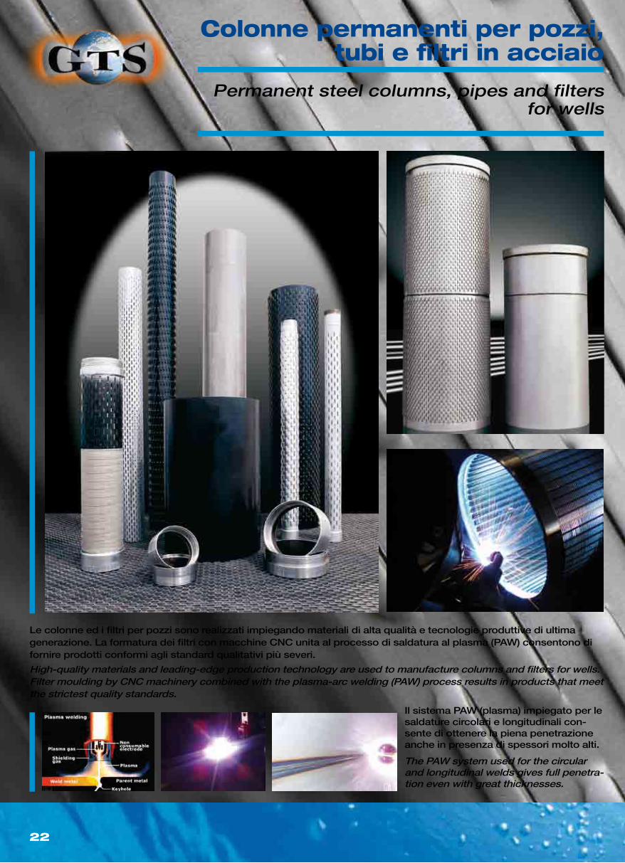
High-quality materials and leading-edge production technology are used to manufacture columns and filters for wells. Filter moulding by CNC machinery combined with the plasma-arc welding (PAW) process results in products that meet the strictest quality standards.
The PAW system used for the circular and longitudinal welds gives full penetra-tion even with great thicknesses.
Permanent steel columns, pipes and filters for wells
Le colonne ed i filtri per pozzi sono realizzati impiegando materiali di alta qualità e tecnologie produttive di ultima generazione. La formatura dei filtri con macchine CNC unita al processo di saldatura al plasma (PAW) consentono di fornire prodotti conformi agli standard qualitativi più severi.
Il sistema PAW (plasma) impiegato per le saldature circolari e longitudinali con-sente di ottenere la piena penetrazione anche in presenza di spessori molto alti.
Colonne permanenti per pozzi,tubi e filtri in acciaio
23
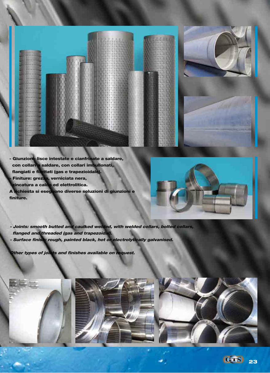
- Joints: smooth butted and caulked welded, with welded collars, bolted collars,
flanged and threaded (gas and trapezoidal).
- Surface finish: rough, painted black, hot or electrolytically galvanised.
Other types of joints and finishes available on request.
- Giunzioni: lisce intestate e cianfrinate a saldare,
con collari a saldare, con collari imbullonati,
flangiati e filettati (gas e trapezioidale).
- Finiture: grezza, verniciata nera,
zincatura a caldo ed elettrolitica.
A richiesta si eseguono diverse soluzioni di giunzioni e
finiture.
24
ØSPESSORETHICKNESS
SLOT
0,50 1,00 1,50 2,00 2,50
mm-inch DN mmOPEN
AREA %l/s
al metroOPEN
AREA %l/s
al metroOPEN
AREA %l/s
al metroOPEN
AREA %l/s
al metroOPEN
AREA %l/s
al metro
114,3 - 4” 100 3 · 4 · 5 2,5 0,30 5,0 0,55 7,5 0,80 10,0 1,00 14,9 1,25
139,7 - 5” 125 3 · 4 · 5 2,5 0,35 5,0 0,65 7,5 0,95 10,0 1,20 14,9 1,50
168 – 6” 150 3 · 4 · 5 · 6 2,5 0,40 5,0 0,75 7,5 1,10 10,0 1,40 14,9 1,75
177,8 – 6”½ - 3 · 4 · 5 · 6 · 7 2,5 0,45 5,0 0,85 7,5 1,25 10,0 1,65 14,9 2,05
219,1 – 8”½ 200 3, · 4 · 5 · 6 · 7 · 8 2,5 0,50 5,0 0,95 7,5 1,35 10,0 1,90 14,9 2,35
244,5 - 250 3 · 4 · 5 · 6 · 7 · 8 2,5 0,60 5,0 1,15 7,5 1,70 10,0 2,20 14,9 2,50
273 -10”¾ 250 3 · 4 · 5 · 6 · 7 · 8 2,5 0,65 5,0 1,25 7,5 1,85 10,0 2,45 14,9 3,00
323,9 – 12”¾ 300 4 · 5 · 6 · 7 · 8 · 10 · 12 2,5 0,75 5,0 1,45 7,5 2,15 10,0 2,80 13,8 3,40
355,6 – 14” 350 4 · 5 · 6 · 7 · 8 · 10 · 12 2,5 0,80 5,0 1,55 7,5 2,30 10,0 3,00 13,8 3,75
406,4 – 16” 400 4 · 5 · 6 · 7 · 8 · 10 · 12 2,5 0,95 5,0 1,85 7,5 2,70 10,0 3,60 13,8 4,50
457,2 – 18” 450 4 · 5 · 6 · 7 · 8 · 10 · 12 2,0 1,00 5,0 1,95 7,5 2,85 10,0 3,85 13,8 4,80
508 – 20” 500 4 · 5 · 6 · 7 · 8 · 10 · 12 2,0 1,05 4,5 2,05 7,5 3,10 10,0 4,00 13,8 5,00
560 – 22 ” 550 5 · 6 · 7 · 8 · 10 · 12 2,0 1,10 4,5 2,15 7,0 3,20 10,0 4,25 13,8 5,20
609,6 - 24” 600 4 · 5 · 6 · 7 · 8 · 10 · 12 2,0 1,20 4,5 2,35 7,0 3,50 9,5 4,60 13,8 5,65
711,2 – 28” 700 5 · 6 · 7 · 8 · 10 · 12 2,0 1,35 4,5 2,65 7,0 3,90 9,5 5,15 13,8 6,45
762 – 30” 750 5 · 6 · 7 · 8 · 10 · 12 2,0 1,55 4,5 3,00 7,0 4,40 9,5 5,90 13,8 7,35
812 – 32” 800 6 · 7 · 8 · 10 · 12 2,0 1,80 4,5 3,50 7,0 5,20 9,5 6,85 12,6 8,50
914,4 – 36” 900 6 · 7 · 8 · 10 · 12 2,0 2,20 4,5 4,25 7,0 6,30 9,5 8,30 12,6 10,30
965,2 – 38” 950 6 · 7 · 8 · 10 · 12 2,0 2,40 4,5 4,60 7,0 6,90 9,5 9,10 12,6 11,50
1016 – 40” 1000 6 · 7 · 8 · 10 · 12 2,0 2,75 4,5 5,35 6,5 7,85 9,0 10,50 12,6 13,10
1200 – 44” 1200 6 · 7 · 8 · 10 · 12 2,0 3,80 4,5 7,20 6,5 10,50 9,0 13,90 12,6 17,50
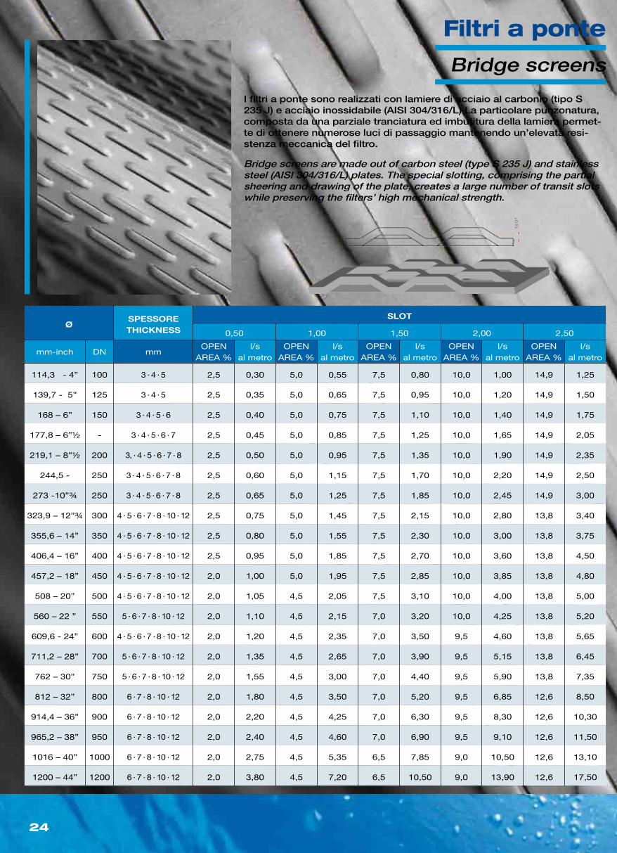
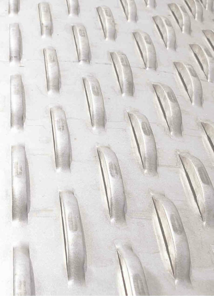
Bridge screens are made out of carbon steel (type S 235 J) and stainless steel (AISI 304/316/L) plates. The special slotting, comprising the partial sheering and drawing of the plate, creates a large number of transit slots while preserving the filters’ high mechanical strength.
Bridge screens
I filtri a ponte sono realizzati con lamiere di acciaio al carbonio (tipo S 235 J) e acciaio inossidabile (AISI 304/316/L) La particolare punzonatura, composta da una parziale tranciatura ed imbutitura della lamiera permet-te di ottenere numerose luci di passaggio mantenendo un’elevata resi-stenza meccanica del filtro.
Filtri a ponte
25
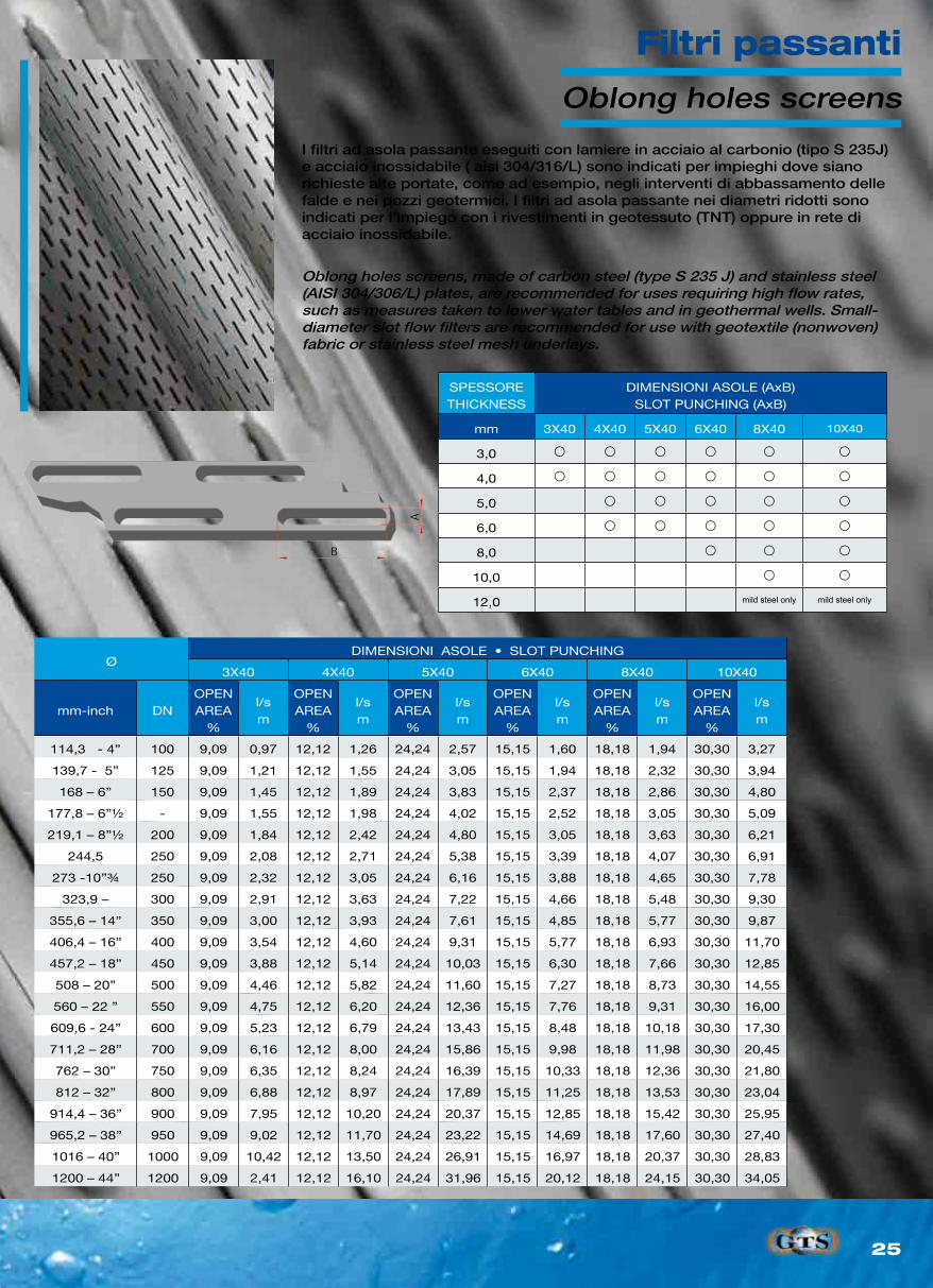
ØDIMENSIONI ASOLE • SLOT PUNCHING
3X40 4X40 5X40 6X40 8X40 10X40
mm-inch DNOPEN AREA
%
l/sm
OPEN AREA
%
l/sm
OPEN AREA
%
l/sm
OPEN AREA
%
l/sm
OPEN AREA
%
l/sm
OPEN AREA
%
l/sm
114,3 - 4” 100 9,09 0,97 12,12 1,26 24,24 2,57 15,15 1,60 18,18 1,94 30,30 3,27
139,7 - 5” 125 9,09 1,21 12,12 1,55 24,24 3,05 15,15 1,94 18,18 2,32 30,30 3,94
168 – 6” 150 9,09 1,45 12,12 1,89 24,24 3,83 15,15 2,37 18,18 2,86 30,30 4,80
177,8 – 6”½ - 9,09 1,55 12,12 1,98 24,24 4,02 15,15 2,52 18,18 3,05 30,30 5,09
219,1 – 8”½ 200 9,09 1,84 12,12 2,42 24,24 4,80 15,15 3,05 18,18 3,63 30,30 6,21
244,5 250 9,09 2,08 12,12 2,71 24,24 5,38 15,15 3,39 18,18 4,07 30,30 6,91
273 -10”¾ 250 9,09 2,32 12,12 3,05 24,24 6,16 15,15 3,88 18,18 4,65 30,30 7,78
323,9 – 300 9,09 2,91 12,12 3,63 24,24 7,22 15,15 4,66 18,18 5,48 30,30 9,30
355,6 – 14” 350 9,09 3,00 12,12 3,93 24,24 7,61 15,15 4,85 18,18 5,77 30,30 9,87
406,4 – 16” 400 9,09 3,54 12,12 4,60 24,24 9,31 15,15 5,77 18,18 6,93 30,30 11,70
457,2 – 18” 450 9,09 3,88 12,12 5,14 24,24 10,03 15,15 6,30 18,18 7,66 30,30 12,85
508 – 20” 500 9,09 4,46 12,12 5,82 24,24 11,60 15,15 7,27 18,18 8,73 30,30 14,55
560 – 22 ” 550 9,09 4,75 12,12 6,20 24,24 12,36 15,15 7,76 18,18 9,31 30,30 16,00
609,6 - 24” 600 9,09 5,23 12,12 6,79 24,24 13,43 15,15 8,48 18,18 10,18 30,30 17,30
711,2 – 28” 700 9,09 6,16 12,12 8,00 24,24 15,86 15,15 9,98 18,18 11,98 30,30 20,45
762 – 30” 750 9,09 6,35 12,12 8,24 24,24 16,39 15,15 10,33 18,18 12,36 30,30 21,80
812 – 32” 800 9,09 6,88 12,12 8,97 24,24 17,89 15,15 11,25 18,18 13,53 30,30 23,04
914,4 – 36” 900 9,09 7,95 12,12 10,20 24,24 20,37 15,15 12,85 18,18 15,42 30,30 25,95
965,2 – 38” 950 9,09 9,02 12,12 11,70 24,24 23,22 15,15 14,69 18,18 17,60 30,30 27,40
1016 – 40” 1000 9,09 10,42 12,12 13,50 24,24 26,91 15,15 16,97 18,18 20,37 30,30 28,83
1200 – 44” 1200 9,09 2,41 12,12 16,10 24,24 31,96 15,15 20,12 18,18 24,15 30,30 34,05
SPESSORETHICKNESS
DIMENSIONI ASOLE (AxB)SLOT PUNCHING (AxB)
mm 3X40 4X40 5X40 6X40 8X40 10X40
3,0
4,0
5,0
6,0
8,0
10,0
12,0 mild steel only mild steel only
Oblong holes screens, made of carbon steel (type S 235 J) and stainless steel (AISI 304/306/L) plates, are recommended for uses requiring high flow rates, such as measures taken to lower water tables and in geothermal wells. Small-diameter slot flow filters are recommended for use with geotextile (nonwoven) fabric or stainless steel mesh underlays.
Oblong holes screens
I filtri ad asola passante eseguiti con lamiere in acciaio al carbonio (tipo S 235J) e acciaio inossidabile ( aisi 304/316/L) sono indicati per impieghi dove siano richieste alte portate, come ad esempio, negli interventi di abbassamento delle falde e nei pozzi geotermici. I filtri ad asola passante nei diametri ridotti sono indicati per l’impiego con i rivestimenti in geotessuto (TNT) oppure in rete di acciaio inossidabile.
Filtri passanti
26
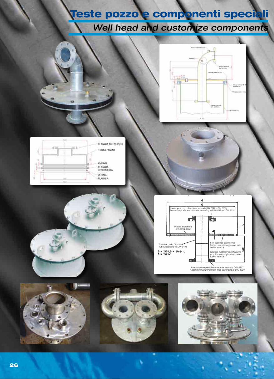
Well head and customize components
Teste pozzo e componenti speciali
G.T.S. s.n.c.
Via Cadut i su l Lavoro , 15/A
46027 SAN BENEDETTO PO (MN)
Te le fono +39 0376 620677
Fax +39 0376 620709
www.gtssnc.com
emai l : in [email protected]
Fil iale
Subsidiary:
Via Ga lvan i , 5
20040 BURAGO MOLGORA (MI )
Te le fono +39 039 6083581
Fax +39 039 6083681
Dis t r ibutore autor i zzatoAutor ized d is t r ibutor
w w w . g t s s n c . c o m