Warcom presse
26
-
Upload
warcom-srl -
Category
Documents
-
view
264 -
download
0
description
Warcom Srl sviluppa e produce Presse Piegatrici, Cesoie, Macchine Taglio al Plasma, Taglio Laser.
Transcript of Warcom presse

Presse Piegatrici / Press brakes
Cesoie a Ghigliottina / Guillotine shears
Taglio Plasma / Plasma cutting
Taglio Laser / Fiber Laser cutting
Lattoneria / Tinsmith Machines
Profilo Aziendale / Company Profile
01
pag. 10
pag. 104
pag. 54
pag. 88
pag. 116
pag. 05
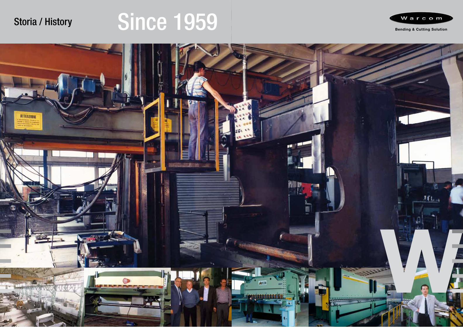
Storia / History Since 1959
0302
04 05
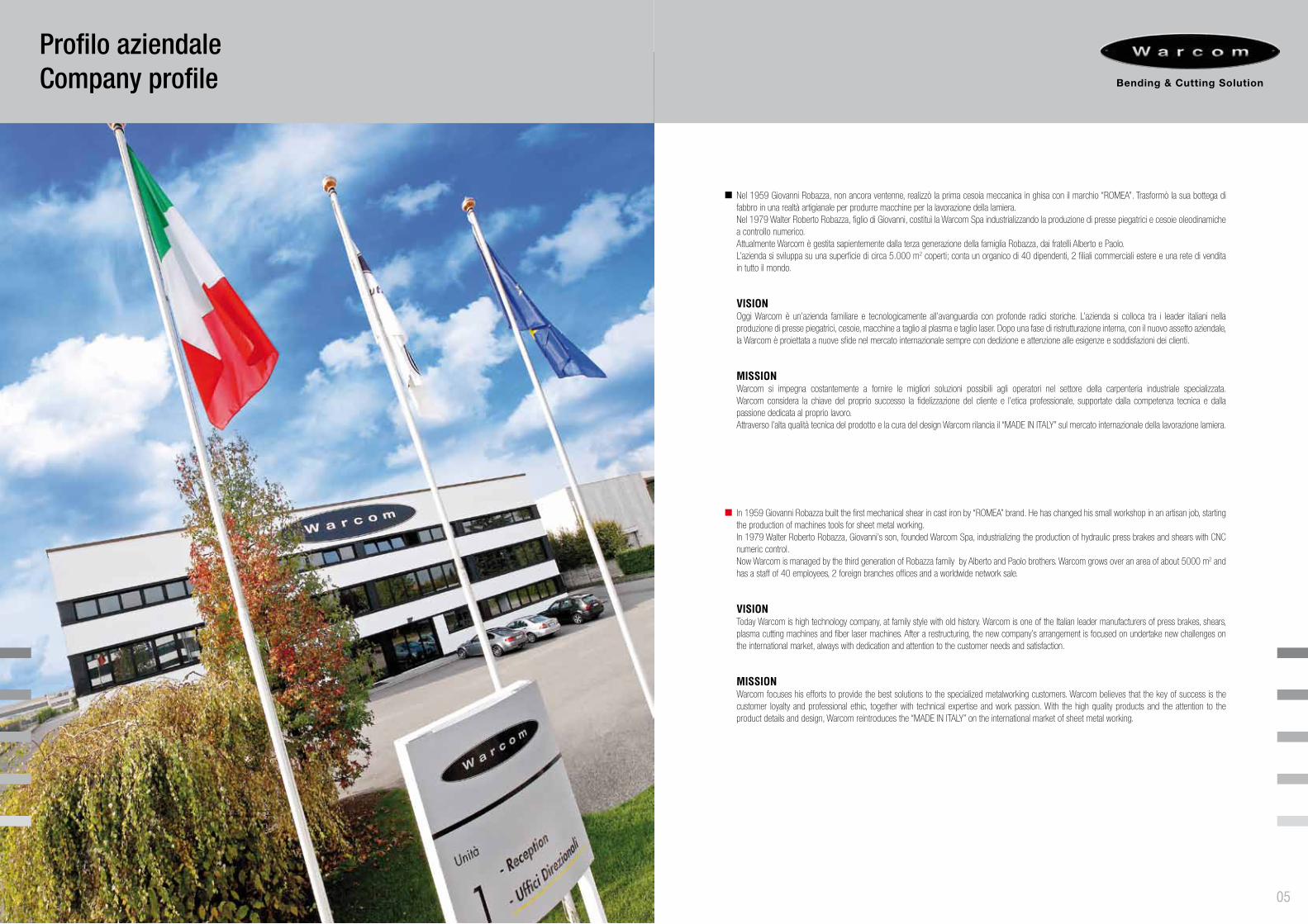
Nel 1959 Giovanni Robazza, non ancora ventenne, realizzò la prima cesoia meccanica in ghisa con il marchio “ROMEA”. Trasformò la sua bottega di fabbro in una realtà artigianale per produrre macchine per la lavorazione della lamiera. Nel 1979 Walter Roberto Robazza, figlio di Giovanni, costituì la Warcom Spa industrializzando la produzione di presse piegatrici e cesoie oleodinamiche a controllo numerico. Attualmente Warcom è gestita sapientemente dalla terza generazione della famiglia Robazza, dai fratelli Alberto e Paolo. L’azienda si sviluppa su una superficie di circa 5.000 m2 coperti; conta un organico di 40 dipendenti, 2 filiali commerciali estere e una rete di vendita in tutto il mondo.
VISIONOggi Warcom è un’azienda familiare e tecnologicamente all’avanguardia con profonde radici storiche. L’azienda si colloca tra i leader italiani nella produzione di presse piegatrici, cesoie, macchine a taglio al plasma e taglio laser. Dopo una fase di ristrutturazione interna, con il nuovo assetto aziendale, la Warcom è proiettata a nuove sfide nel mercato internazionale sempre con dedizione e attenzione alle esigenze e soddisfazioni dei clienti.
MISSIONWarcom si impegna costantemente a fornire le migliori soluzioni possibili agli operatori nel settore della carpenteria industriale specializzata. Warcom considera la chiave del proprio successo la fidelizzazione del cliente e l’etica professionale, supportate dalla competenza tecnica e dalla passione dedicata al proprio lavoro. Attraverso l’alta qualità tecnica del prodotto e la cura del design Warcom rilancia il “MADE IN ITALY” sul mercato internazionale della lavorazione lamiera.
In 1959 Giovanni Robazza built the first mechanical shear in cast iron by “ROMEA” brand. He has changed his small workshop in an artisan job, starting the production of machines tools for sheet metal working. In 1979 Walter Roberto Robazza, Giovanni’s son, founded Warcom Spa, industrializing the production of hydraulic press brakes and shears with CNC numeric control. Now Warcom is managed by the third generation of Robazza family by Alberto and Paolo brothers. Warcom grows over an area of about 5000 m2 and has a staff of 40 employees, 2 foreign branches offices and a worldwide network sale.
VISIONToday Warcom is high technology company, at family style with old history. Warcom is one of the Italian leader manufacturers of press brakes, shears, plasma cutting machines and fiber laser machines. After a restructuring, the new company’s arrangement is focused on undertake new challenges on the international market, always with dedication and attention to the customer needs and satisfaction.
MISSIONWarcom focuses his efforts to provide the best solutions to the specialized metalworking customers. Warcom believes that the key of success is the customer loyalty and professional ethic, together with technical expertise and work passion. With the high quality products and the attention to the product details and design, Warcom reintroduces the “MADE IN ITALY” on the international market of sheet metal working.
Profilo aziendaleCompany profile
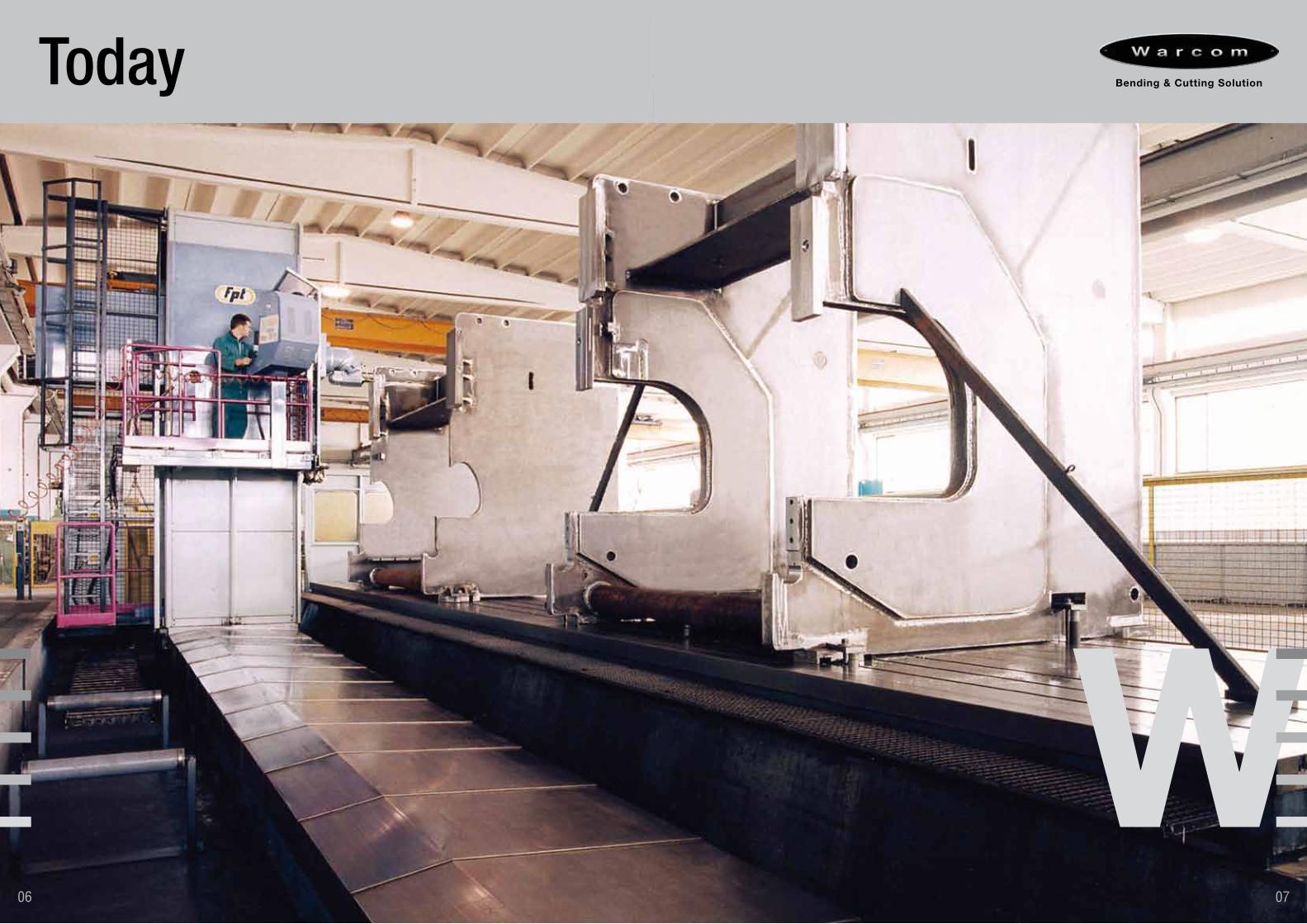
Today
0706
0908
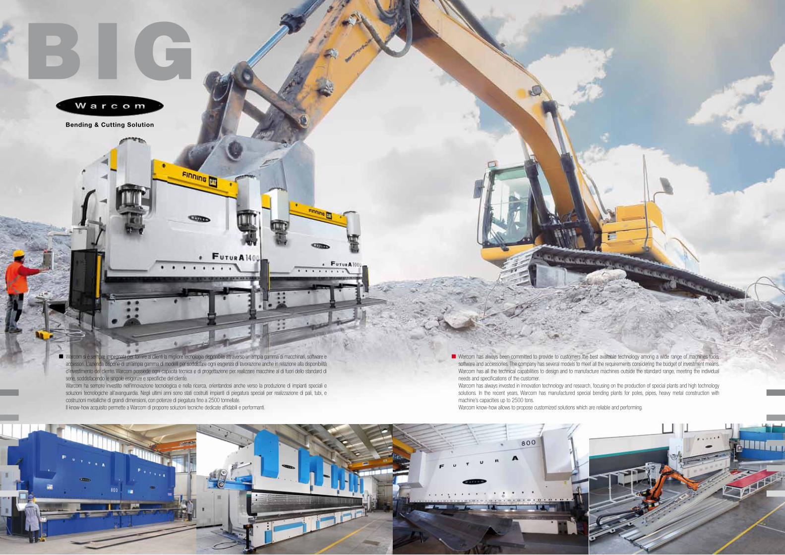
Warcom has always been committed to provide to customers the best available technology among a wide range of machines tools, software and accessories. The company has several models to meet all the requirements considering the budget of investment means. Warcom has all the technical capabilities to design and to manufacture machines outside the standard range, meeting the individual needs and specifications of the customer.Warcom has always invested in innovation technology and research, focusing on the production of special plants and high technology solutions. In the recent years, Warcom has manufactured special bending plants for poles, pipes, heavy metal construction with machine’s capacities up to 2500 tons. Warcom know-how allows to propose customized solutions which are reliable and performing.
Warcom si è sempre impegnata per fornire ai clienti la migliore tecnologia disponibile attraverso un’ampia gamma di macchinari, software e accessori. L’azienda dispone di un’ampia gamma di modelli per soddisfare ogni esigenza di lavorazione anche in relazione alla disponibilità d’investimento del cliente. Warcom possiede ogni capacità tecnica e di progettazione per realizzare macchine al di fuori dello standard di serie, soddisfacendo le singole esigenze e specifiche del cliente.Warcom ha sempre investito nell’innovazione tecnologica e nella ricerca, orientandosi anche verso la produzione di impianti speciali e soluzioni tecnologiche all’avanguardia. Negli ultimi anni sono stati costruiti impianti di piegatura speciali per realizzazione di pali, tubi, e costruzioni metalliche di grandi dimensioni, con potenze di piegatura fino a 2500 tonnellate. Il know-how acquisito permette a Warcom di proporre soluzioni tecniche dedicate affidabili e performanti.
1110
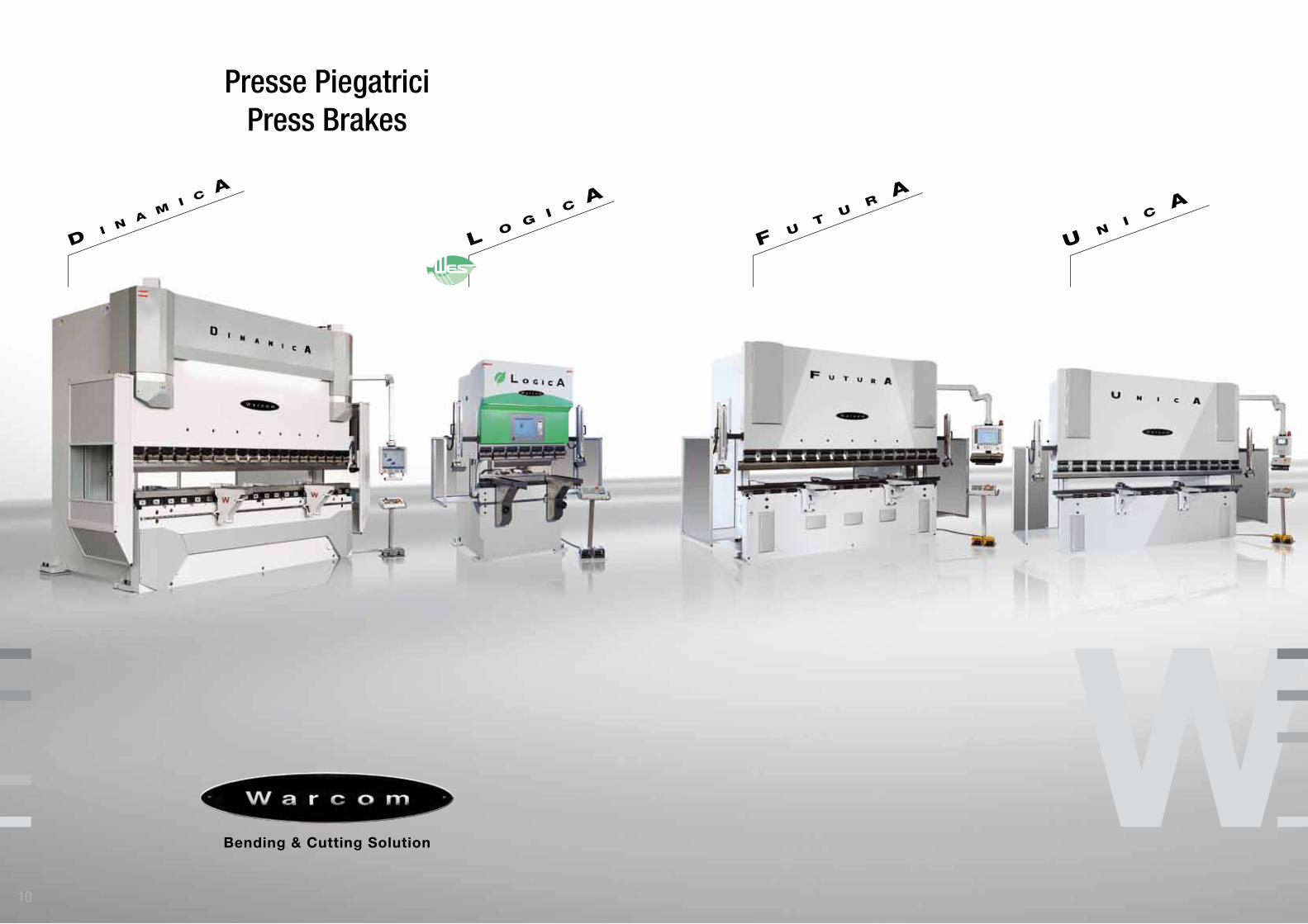
Presse PiegatriciPress Brakes
Tipologia di piegaturaBending tecnique
13
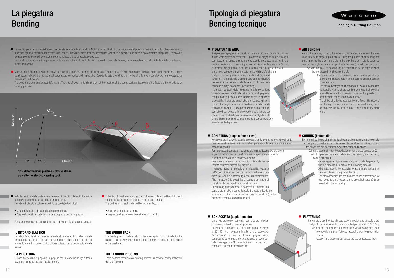
PIEGATURA IN ARIATra i processi di piegatura, la piegatura in aria e la più semplice e la più utilizzata in una vasta gamma di produzioni. Il processo di piegatura in aria si esegue per mezzo di un punzone superiore che scendendo pressa la lamiera in una matrice inferiore a V. Durante il processo di piegatura la lamiera ha 3 punti di contatto con gli utensili (uno con il vertice del punzone e due con la matrice). L’angolo di piega è determinato dalla profondità alla quale il punzone preme la lamiera nella matrice, quindi variabile. Il ritorno elastico è compensato da una maggiore penetrazione permettendo alla lamiera di ritornare nella posizione di piega desiderata (over-bending). I principali vantaggi della piegatura in aria sono: forza richiesta inferiore rispetto alle altre tecniche di piegatura, che permette di piegare anche lamiere di grosso spessore e possibilità di ottenere angoli diversi utilizzando gli stessi utensili. La piegatura in aria è caratterizzata dalla iniziale difficoltà nel trovare la giusta penetrazione del punzone che permette di compensare il ritorno elastico della lamiera per ottenere l’angolo desiderato. Questo criterio obbliga la scelta di una pressa piegatrice ad alta tecnologia per ottenere uno elevato standard qualitativo.
AIR BENDINGAmong the bending process, the air bending is the most simple and the most used for a wide range of productions. During the process of air bending, the punch presses the sheet in a V-die. In this way the sheet metal is deformed creating the angle in the contact point with the tools (one with the punch and
two with the die). The bending angle is determined by the depth to which the tool pressed the sheet into the die.
The spring back is compensated by a greater penetration allowing the sheet to return to the desired bending position (over-bending). The main advantages of air bending are: weak force required comparable with the others bending technique, that gives the possibility to bend thick material, moreover the possibility to bend different angles using the same tools. The air bending is characterized by a difficult initial stage to find the right bending angle due to the sheet spring back, consequently by the need to have a high technology press brake.
CONIATURA (piega a fondo cava)Nella coniatura, il punzone superiore pressa la lamiera completamente fino al fondo cava nella matrice inferiore, in modo che il punzone, la lamiera, e la matrice siano accoppiati insieme. Per il processo di coniatura, il punzone e la matrice devono avere lo stesso angolo di inclinazione. La coniatura è utilizzata principalmente per la piegatura di angoli a 90° con lamiera sottile.Con questo processo la lamiera è coniata eliminando l’effetto del ritorno elastico del materiale.I vantaggi sono la precisione e ripetibilità costante dell’angolo di piegatura dovuto a una tecnica di lavorazione molto più simile allo stampaggio che alla deformazione. Altro vantaggio è la possibilità di ottenere un raggio di piegatura inferiore rispetto alla piegatura in aria. Gli svantaggi principali sono la necessità di utilizzare una copia di utensili diversi per ogni angolo di piegatura desiderato e la necessità di utilizzare un’elevata forza di piegatura (5 volte maggiore rispetto alla piegatura in aria).
COINING (bottom die)By the coining, the punch presses the sheet metal completely in the lower die,
so that punch, sheet metal and die are coupled together. For coining process the punch and die must match exactly the same angle shape.
Coining is used mainly for the production of items press bended at 90°. With this process the sheet is deformed permanently and the spring
back is minimized. The advantages are high angle accuracy and constant repeatability,
due to a process more similar to the molding process. Other advantage is the possibility to get a smaller radius than the one obtained during the air bending. The main disadvantages are the need to use different tools for each bending angle request and to use a high force (5 times more that in the air bending).
SCHIACCIATA (appiattimento)Viene generalmente applicata per ottenere rigidità, protezione dei bordi ed evitare spigoli vivi. Si tratta di un processo a 2 fasi: una prima pre-piega a 26°-35° (con piegatura in aria) e una successiva “schiacciatura” in cui la lamiera piegata viene completamente o parzialmente appiattita, a seconda della forza applicata. Solitamente è un processo che comporta l’ utilizzo di utensili dedicati.
FLATTENINGIt is generally used to get stiffness, edge protection and to avoid sharp
edges. It is a process made in 2 steps: a first pre-bend at 26°-35° (by air bending) and a subsequent flattening in which the bending sheet
is completely or partially flattened, according with the specification request. Usually it is a process that involves the use of dedicated tools.
La piegaturaBending
12
La maggior parte dei processi di lavorazione della lamiera include la piegatura. Molti settori industriali sono basati su questa tipologia di lavorazione: automotive, arredamento, macchine agricole, macchine movimento terra, edilizia, ferroviario, termo-tecnico, aeronautica, elettronica e navale. Nonostante la sua apparente semplicità, il processo di piegatura è una tecnica di lavorazione molto complessa che va conosciuta e appresa. La piegatura è la deformazione permanente della lamiera. La tipologia di utensili, il carico di rottura della lamiera, il ritorno elastico sono alcuni dei fattori da considerare in questa lavorazione.
Most of the sheet metal working involves the bending process. Different industries are based on this process: automotive, furniture, agricultural equipment, building construction, railways, thermo-technical, aeronautics, electronics and shipbuilding. Despite its ostensible simplicity, the bending is a very complex working process to be learned and understood. The bend is the permanent sheet deformation. The type of tools, the tensile strength of the sheet metal, the spring back are just some of the factors to be considered on bending process.
Nella lavorazione della lamiera, una delle condizioni più critiche è ottenere le tolleranze geometriche richieste per il prodotto finito. Il risultato di piegatura ottimale è definito da due fattori principali:
• Valore dell’angolo di piega nelle tolleranze richieste.• Angolo di piegatura costante su tutta la lunghezza del pezzo piegato.
Per ottenere un risultato ottimale è indispensabile approfondire alcuni concetti.
IL RITORNO ELASTICOIl risultato della piegatura di una lamiera è legato anche al ritorno elastico della lamiera: questo effetto è dato dal naturale recupero elastico del materiale nel momento in cui è rimosso il carico di forza utilizzato per la deformazione della stessa.
LA PIEGATURACi sono tre tecniche di piegatura: la piega in aria, la coniatura (piega a fondo cava) e la “piega schiacciata” (appiattimento).
In the field of sheet metalworking, one of the most critical conditions is to reach the geometrical tolerances required on the finished product. The best bending result is defined by two main factors:
• Accuracy of the bending angle.• Regular bending angle on the entire bending length.
THE SPRING BACKThe bending result is related also to the sheet spring back: this effect is the natural elastic recovery when the force load is removed used for the deformation of the sheet metal.
THE BENDING PROCESSThere are three techniques of bending process: air bending, coining (at bottom die) and flattening.
e
m
= deformazione plastica - plastic strain= ritorno elastico - spring back
R
linea di piega - bending line
t
w
bsenso di laminazioneRoll mill direction
Acciaio ad alta resistenzaHigh strength steel
15
ACCIAIO AD ALTA RESISTENZA (HSS)
Ai materiali tradizionalmente utilizzati in ambito dei lavori di carpenteria (acciaio al carbonio, acciaio inossidabile e alluminio) sono stati affiancati i cosiddetti ACCIAI ALTORESISTENZIALI o HSS. Dato l’elevato carico di rottura, i materiali HSS richiedono un’impostazione specifica del processo di piegatura e della scelta degli utensili. La tabella che segue riporta, per i diversi tipi di materiale HSS, il raggio minimo del punzone (R) e l’apertura consigliata della matrice a V (W), relativi allo spessore della lamiera in lavorazione (t) e al senso di laminazione (per pieghe a 90°).La formula per il calcolo della forza necessaria alla piegatura di materiali alto resistenziali è diversa da quella canonica in quanto deve considerare diversi fattori aggiuntivi e può essere cosi riassunta:
F tot = forza totale relativa alla lunghezza del pezzob = = lunghezza di piegaturat = spessore della lamieraW = larghezza cavaRm = carico di rottura in MPa (vedi tabella sotto)
HIGH STRENGTH STEEL (HSS)
Besides the material usually used in sheet metal working (carbon steel, stainless steel and aluminum), the so-called High Strength Steel (HSS) are used. Considering the high tensile strength, HSS material requires a specific setting of the bending process and of the choice of the tools. The following chart shows, for the different types of HSS material, the minimum punch radius (R) and recommended opening of the V-die (W), in relation to the thickness of the work piece (t) and the millwork direction (for 90° bending).
The calculation to get the force needed to bend HSS material is different from the standard one, as we have to consider different factors. See as follows:
F tot = total force compared to the length of the pieceb = bending length
t = thickness W = opening of the V-die
Rm = tensile strength in MPa (see chart here below)
Thichness[mm]
TransverseR/t
ParallelR/t
TransverseW/t
ParallelW/t
Ritorno elasticoSpring back
[ ° ]
S 355 (EN 10025) 2,5 3,0 7,5 8,5 3-5
WELDOX 700
t < 88 ≥ t < 20
t ≥ 20
1,52,03,0
2,03,04,0
7,07,08,5
8,58,510,0
6-10
WELDOX 960
t < 88 ≥ t < 20
t ≥ 20
2,53,04,0
3,04,05,0
8,58,510,0
10,010.012,0
8-12
WELDOX 1030
t < 88 ≥ t < 20
t ≥ 20
3,03,54,5
3,54,55,5
9,09,011,0
10,011.013,0
10-32
WELDOX 1100
t < 88 ≥ t < 20
t ≥ 20
3,54,05,0
4,05,06,0
10.010,012,0
10,012,014,0
11-18
WELDOX 1300
t < 66 < t < 10
3,54,0
4,05,0
10,012,0
12,014,0 12-45
HARDOX 400
t < 88 ≥ t < 20
t ≥ 20
2,53,04,5
3,04,05,0
8,510,012,0
10,010,012,0
9-13
HARDOX 450
t < 88 ≥ t < 20
t ≥ 20
3,54,05,0
4,05,06,0
10,010,012,0
10,012,014,0
11-18
HARDOX 500
t < 88 ≥ t < 20
t ≥ 20
4,05,07,0
5,06,08,0
10,012,016,0
12,014,018,0
12-20
1,6 x b x t2 x Rm
10000 x WF tot ( +/- 20%) =
1,6 x b x t2 x Rm
10000 x WF tot ( +/- 20%) =
Tensile Strength Rm
[ MPa ]
Extension As
[ % ]
DurezzaHardness[ HBW ]
S 355 (EN 10025) 550 28 ~ 180
WELDOX 700 860 17 ~ 270
WELDOX 900 1030 15 ~ 330
WELDOX 960 1070 15 ~ 340
WELDOX 1030 1340 11 ~ 430
WELDOX 1100 1440 11 ~ 460
WELDOX 1300 1540 10 ~ 490
HARDOX 400 1250 10 ~ 400
HARDOX 450 1440 9 ~ 450
HARDOX 500 1550 8 ~ 500
Forza di piegaBending force
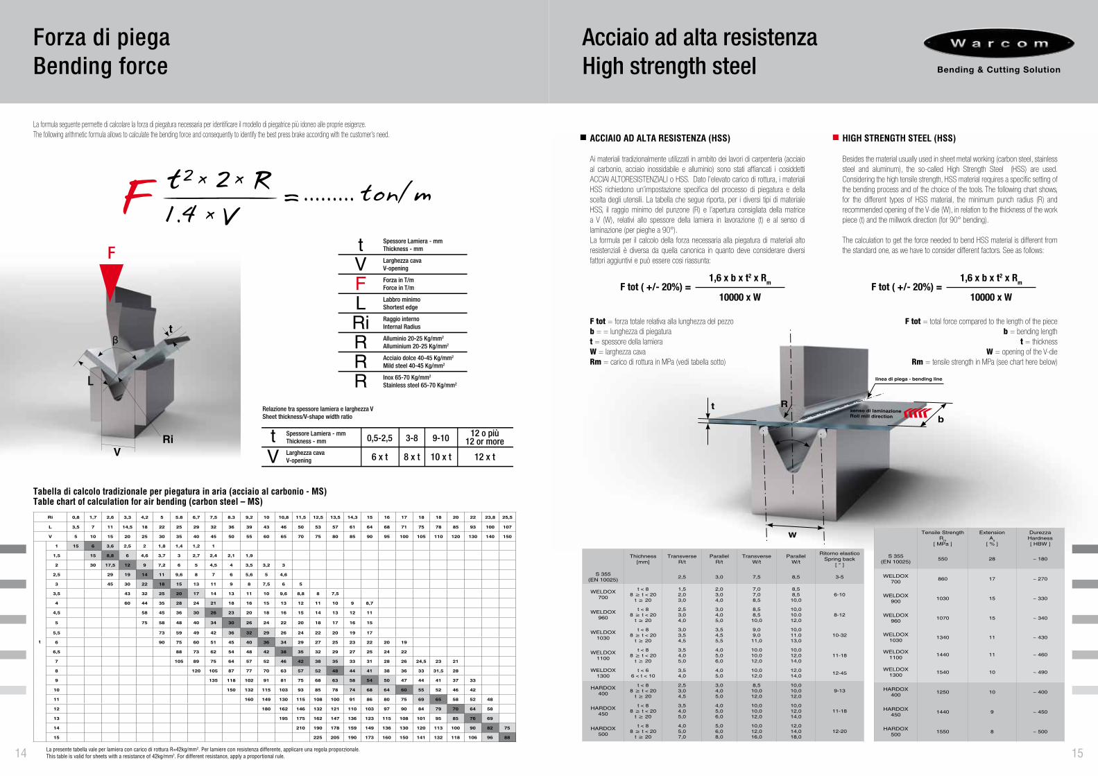
La formula seguente permette di calcolare la forza di piegatura necessaria per identificare il modello di piegatrice più idoneo alle proprie esigenze.The following arithmetic formula allows to calculate the bending force and consequently to identify the best press brake according with the customer’s need.
Ri 0,8 1,7 2,6 3,3 4,2 5 5.8 6,7 7,5 8.3 9,2 10 10,8 11,5 12,5 13,5 14,3 15 16 17 18 18 20 22 23,8 25,5
L 3,5 7 11 14,5 18 22 25 29 32 36 39 43 46 50 53 57 61 64 68 71 75 78 85 93 100 107
V 5 10 15 20 25 30 35 40 45 50 55 60 65 70 75 80 85 90 95 100 105 110 120 130 140 150
t
1 15 6 3,6 2,5 2 1,8 1,4 1,2 1
1,5 15 8,8 6 4,6 3,7 3 2,7 2,4 2,1 1,9
2 30 17,5 12 9 7,2 6 5 4,5 4 3,5 3,2 3
2,5 29 19 14 11 9,6 8 7 6 5,6 5 4,6
3 45 30 22 18 15 13 11 9 8 7,5 6 5
3,5 43 32 25 20 17 14 13 11 10 9,6 8,8 8 7,5
4 60 44 35 28 24 21 18 16 15 13 12 11 10 9 8,7
4,5 58 45 36 30 26 23 20 18 16 15 14 13 12 11
5 75 58 48 40 34 30 26 24 22 20 18 17 16 15
5,5 73 59 49 42 36 32 29 26 24 22 20 19 17
6 90 75 60 51 45 40 36 34 29 27 25 23 22 20 19
6,5 88 73 62 54 48 42 38 35 32 29 27 25 24 22
7 105 89 75 64 57 52 46 42 38 35 33 31 28 26 24,5 23 21
8 120 105 87 77 70 63 57 52 48 44 41 38 36 33 31,5 28
9 135 118 102 91 81 75 68 63 58 54 50 47 44 41 37 33
10 150 132 115 103 93 85 78 74 68 64 60 55 52 46 42
11 160 149 130 115 108 100 91 86 80 75 69 65 58 52 48
12 180 162 146 132 121 110 103 97 90 84 79 70 64 58
13 195 175 162 147 136 123 115 108 101 95 85 76 69
14 210 190 178 159 149 136 130 120 113 100 90 82 75
15 225 205 190 173 160 150 141 132 118 106 96 88
La presente tabella vale per lamiera con carico di rottura R=42kg/mm2. Per lamiere con resistenza differente, applicare una regola proporzionale.This table is valid for sheets with a resistance of 42kg/mm2. For different resistance, apply a proportional rule.
VRi
t
F
L
tVFLRiRRR
Spessore Lamiera - mmThickness - mm
Larghezza cavaV-opening
Forza in T/mForce in T/m
Labbro minimoShortest edge
Raggio internoInternal Radius
Alluminio 20-25 Kg/mm2
Alluminium 20-25 Kg/mm2
Acciaio dolce 40-45 Kg/mm2
Mild steel 40-45 Kg/mm2
Inox 65-70 Kg/mm2
Stainless steel 65-70 Kg/mm2
tV
Spessore Lamiera - mmThickness - mm 0,5-2,5 3-8 9-10 12 o più
12 or more
6 x t 8 x t 10 x t 12 x tLarghezza cavaV-opening
Relazione tra spessore lamiera e larghezza VSheet thickness/V-shape width ratio
t2 x
x
x21.4 V =......... ton/mRF
14
Tabella di calcolo tradizionale per piegatura in aria (acciaio al carbonio - MS)Table chart of calculation for air bending (carbon steel – MS)
FY1
L
FY2
F
Forza di piegaturaBending Force
16
L
1/2 L
3/4 L
1/3 L
2/3 L
1/2 L
Fmax=100%
Fmax= 60%
Fmax= 70%
Fmax= 50%
Fmax= 65%
Fmax= 65%
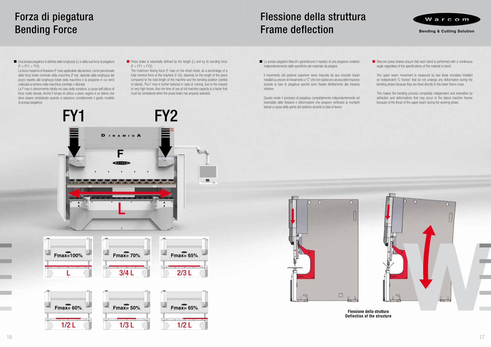
Una pressa piegatrice è definita dalla lunghezza (L) e dalla sua forza di piegatura (F = FY1 + FY2).La forza massima di flessione (F max) applicabile alla lamiera, come percentuale della forza totale nominale della macchina (F tot), dipende dalla lunghezza del pezzo rispetto alla lunghezza totale della macchina e la posizione in cui verrà collocata la lamiera nella macchina (centrale o laterale). La F max è ulteriormente ridotta nel caso della coniatura, a causa dell’utilizzo di forze molto elevate. Anche il tempo di utilizzo a pieno regime è un fattore che deve essere considerato quando si seleziona correttamente il giusto modello di pressa piegatrice.
Press brake is essentially defined by the length (L) and by its bending force (F = FY1 + FY2).The maximum flexing force (F max) on the sheet metal, as a percentage of a total nominal force of the machine (F tot), depends on the length of the piece compared to the total length of the machine and the bending position (central or lateral). The F max is further reduced in case of coining, due to the request of very high forces. Also the time of use at full machine capacity is a factor that must be considered when the press brake has properly selected.
Flessione della strutturaDeflection of the structure
Le presse piegatrici Warcom garantiscono il risultato di una piegatura costante indipendentemente dalle specifiche del materiale da piegare.
Il movimento del pestone superiore viene misurata da due encoder lineari installati su ancore di rilevamento a “C” che non subiscono alcuna deformazione durante la fase di piegatura perché sono fissate direttamente alla traversa inferiore.
Questo rende il processo di piegatura completamente indipendentemente ed insensibile dalle flessioni e deformazioni che possono verificarsi ai montanti laterali a causa della spinta del pestone durante la fase di lavoro.
Warcom press brakes ensure that each bend is performed with a continuous angle regardless of the specifications of the material to bend.
The upper beam movement is measured by two linear encoders installed on independent “C frames” that do not undergo any deformation during the bending phase because they are fixed directly to the lower frame-cross.
This makes the bending process completely independent and insensitive by deflection and deformations that may occur to the lateral machine frames because of the thrust of the upper beam during the working phase.
Flessione della strutturaFrame deflection
17
20
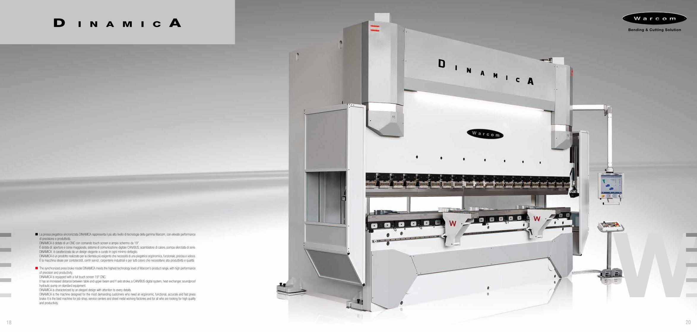
La pressa piegatrice sincronizzata DINAMICA rappresenta il più alto livello di tecnologia della gamma Warcom, con elevate performance di precisione e produttività.DINAMICA è dotata di un CNC con comando touch screen e ampio schermo da 19”. È dotata di: aperture e corse maggiorate, sistema di comunicazione digitale CAN/BUS, scambiatore di calore, pompa silenziata di serie.DINAMICA è caratterizzata da un design elegante e curato in ogni minimo dettaglio. DINAMICA è un prodotto realizzato per la clientela più esigente che necessità di una piegatrice ergonomica, funzionale, precisa e veloce. È la macchina ideale per contoterzisti, centri servizi, carpenterie industriali e per tutti coloro che necessitano alta produttività e qualità.
The synchronized press brake model DINAMICA meets the highest technology level of Warcom’s product range, with high performance of precision and productivity. DINAMICA is equipped with a full touch screen 19” CNC.It has an increased distance between table and upper beam and Y axis stroke, a CAN/BUS digital system, heat exchanger, soundproof hydraulic pump on standard equipment.DINAMICA is characterized by an elegant design with attention to every details.DINAMICA is the machine designed for the most demanding customers who need an ergonomic, functional, accurate and fast press brake. It is the best machine for job-shop, service centers and sheet metal working factories and for all who are looking for high quality and productivity.
18
DCSDynamic Crowning System
90°
90°>90° 90°90°90° <90°90°
By DCS
90°
La movimentazione verticale del pestone della DINAMICA avviene tramite doppie guide temprate e rettificate con cuscinetti a rulli in modo da ridurre al minimo l’attrito dinamico e il rumore dello scorrimento. Grazie a questo sistema di guide DINAMICA può raggiungere elevate velocità di avvicinamento e risalita garantendo alti standard produttivi.
The sliding movement of DINAMICA’s upper beam is through double hardened and ground guides with roller bearings in order to reduce at the minimum the dynamic friction and have smooth movement.Thanks to this sliding system, DINAMICA can reach the highest approach and return speed, guaranteeing high performance.
21 22
Sistemi di guidaSliding system
DINAMICA è equipaggiata di serie con il sistema dinamico attivo di compensazione della traversa inferiore (bombatura) modello DCS PLUS, uno dei più versatili e funzionali sistemi disponibili sul mercato. DCS PLUS è completamente automatico gestito dal CNC che attraverso il sistema idraulico e dei sensori di rilevamento, crea il controllo e gestione della bombatura a loop-chiuso. Il sistema rileva in termini assoluti e non teorici, le minime deformazioni della struttura attraverso due sensori (uno superiore posizionato nel pestone ed uno inferiore posizionato nella traversa inferiore). Il sistema interviene in modo istantaneo, deformando la traversa inferiore tramite dei cilindri idraulici che vengono pilotati da un circuito oleodinamico indipendente. La particolare conformazione della traversa inferiore composta da tre strutture assemblate in verticale ed appoggiate su due supporti a mezza luna conica rende la traversa inferiore completamente svincolata dalla struttura portante della macchina ed assicura un movimento elastico ed autonomo della stessa. Ulteriori sensori di pressione sono posizionati sui cilindri superiori per rilevare lo spessore e la resistenza che oppone il materiale che varia anche al variare della lunghezza della lamiera. Questi dati reali rilevati vengono automaticamente elaborati dal CNC per ricalcolare la forza e la penetrazione dell’utensile rispetto ai calcoli teorici che il CNC avrebbe eseguito senza questi dispositivi di rilevamento. Questo sistema ottimizza e perfeziona il risultato del processo di piegatura. Il sistema DCS PLUS garantisce l’angolo di piegatura costante lungo tutta la lunghezza di piega, senza la necessità di un intervento di correzione da parte dell’operatore. Il sistema DCS PLUS può essere installato, con un costo aggiuntivo, anche nella serie FUTURA che adotta di serie il sistema di centinatura parametrico.
DINAMICA is equipped as standard with DCS PLUS, Dynamic Crowning System. One of the most versatile and functional crowning system on the market. DCS PLUS is fully automatic managed by the CNC through the hydraulic system and sensor detection, control and management of the crowning at closed-loop. The system determines in absolute and non theoretical terms any minimum deformation of the machine frame through two sensors (one on the upper beam and the other on the lower table).The system works immediately deforming the lower beam through to the cylinders that are driven by an independent hydraulic circuit. The particular shape of the lower frame-cross, sheared into three vertical frames placed on the double conical half moon-shaped supports, gives the lower frames-cross completely and disengaged from the main machine’s frames, ensuring an independent and elastic movement of the same. Other pressure sensors located on the upper cylinders detect the thickness, the material strength according with the length. These actual data are automatically processed by the CNC to recalculate the bending force and the punch penetration compared with theoretical calculations that the CNC would have done without these sensing devices. This system optimizes and improves the result of the bending process. The DCS PLUS system ensures the bending angle constant along the entire bending length, without the need for an intervention of correction by the operator. DCS PLUS system can be supplied on request also on FUTURA model that uses as standard the parametric crowning system.
23
Registro posteriore Backgauge M6
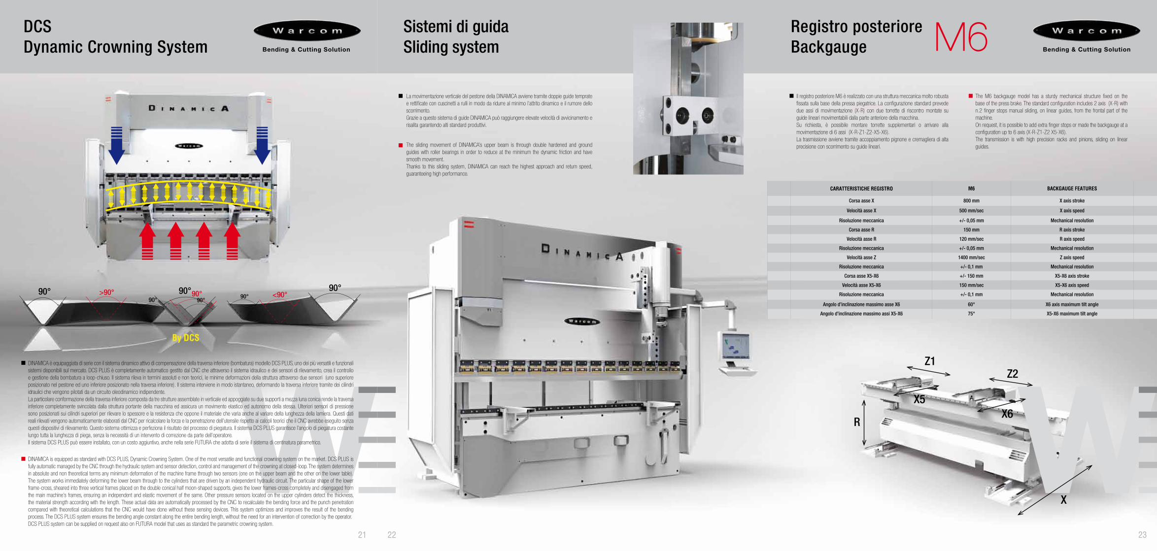
CARATTERISTICHE REGISTRO M6 BACKGAUGE FEATURES
Corsa asse X 800 mm X axis stroke
Velocità asse X 500 mm/sec X axis speed
Risoluzione meccanica +/- 0,05 mm Mechanical resolution
Corsa asse R 150 mm R axis stroke
Velocità asse R 120 mm/sec R axis speed
Risoluzione meccanica +/- 0,05 mm Mechanical resolution
Velocità asse Z 1400 mm/sec Z axis speed
Risoluzione meccanica +/- 0,1 mm Mechanical resolution
Corsa asse X5-X6 +/- 150 mm X5-X6 axis stroke
Velocità asse X5-X6 150 mm/sec X5-X6 axis speed
Risoluzione meccanica +/- 0,1 mm Mechanical resolution
Angolo d’inclinazione massimo asse X6 60° X6 axis maximum tilt angle
Angolo d’inclinazione massimo assi X5-X6 75° X5-X6 maximum tilt angle
Il registro posteriore M6 è realizzato con una struttura meccanica molto robusta fissata sulla base della pressa piegatrice. La configurazione standard prevede due assi di movimentazione (X-R) con due torrette di riscontro montate su guide lineari movimentabili dalla parte anteriore della macchina.Su richiesta, è possibile montare torrette supplementari o arrivare alla movimentazione di 6 assi (X-R-Z1-Z2-X5-X6).La trasmissione avviene tramite accoppiamento pignone e cremagliera di alta precisione con scorrimento su guide lineari.
The M6 backgauge model has a sturdy mechanical structure fixed on the base of the press brake. The standard configuration includes 2 axis (X-R) with n.2 finger stops manual sliding, on linear guides, from the frontal part of the machine. On request, it is possible to add extra finger stops or made the backgauge at a configuration up to 6 axis (X-R-Z1-Z2 X5-X6). The transmission is with high precision racks and pinions, sliding on linear guides.
R
Z1Z2
X6X5
X
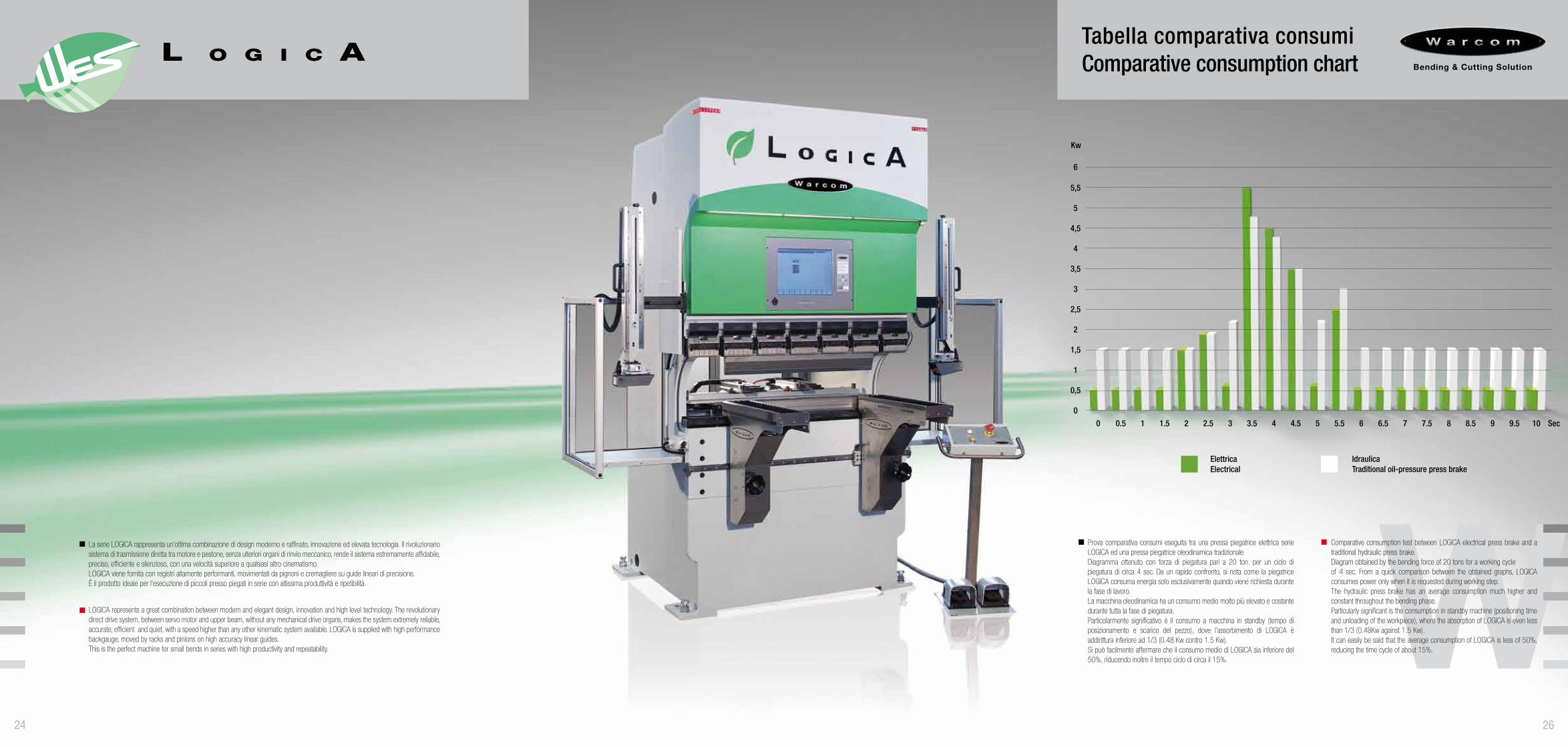
La serie LOGICA rappresenta un’ottima combinazione di design moderno e raffinato, innovazione ed elevata tecnologia. Il rivoluzionario sistema di trasmissione diretta tra motore e pestone, senza ulteriori organi di rinvio meccanico, rende il sistema estremamente affidabile, preciso, efficiente e silenzioso, con una velocità superiore a qualsiasi altro cinematismo. LOGICA viene fornita con registri altamente performanti, movimentati da pignoni e cremagliere su guide lineari di precisione. È il prodotto ideale per l’esecuzione di piccoli presso piegati in serie con altissima produttività e ripetibilità.
LOGICA represents a great combination between modern and elegant design, innovation and high level technology. The revolutionary direct drive system, between servo motor and upper beam, without any mechanical drive organs, makes the system extremely reliable, accurate, efficient and quiet, with a speed higher than any other kinematic system available. LOGICA is supplied with high performance backgauge, moved by racks and pinions on high accuracy linear guides. This is the perfect machine for small bends in series with high productivity and repeatability.
24 26
Tabella comparativa consumiComparative consumption chart
0 3 6.51.5 4.5 80.5 3.5 72 5 8.5 9.51 4 7.52.5 65.5 9 10
0
0,5
1,5
1
2
2,5
3
3,5
4
4,5
5
5,5
6
Kw
Sec
Prova comparativa consumi eseguita tra una pressa piegatrice elettrica serie LOGICA ed una pressa piegatrice oleodinamica tradizionale.Diagramma ottenuto con forza di piegatura pari a 20 ton. per un ciclo di piegatura di circa 4 sec. Da un rapido confronto, si nota come la piegatrice LOGICA consuma energia solo esclusivamente quando viene richiesta durante la fase di lavoro.La macchina oleodinamica ha un consumo medio molto più elevato e costante durante tutta la fase di piegatura.Particolarmente significativo è il consumo a macchina in standby (tempo di posizionamento e scarico del pezzo), dove l’assorbimento di LOGICA è addirittura inferiore ad 1/3 (0.48 Kw contro 1.5 Kw).Si può facilmente affermare che il consumo medio di LOGICA sia inferiore del 50%, riducendo inoltre il tempo ciclo di circa il 15%.
Comparative consumption test between LOGICA electrical press brake and a traditional hydraulic press brake.Diagram obtained by the bending force of 20 tons for a working cycle of 4 sec. From a quick comparison between the obtained graphs, LOGICA consumes power only when it is requested during working step. The hydraulic press brake has an average consumption much higher and constant throughout the bending phase. Particularly significant is the consumption in standby machine (positioning time and unloading of the workpiece), where the absorption of LOGICA is even less than 1/3 (0.48Kw against 1.5 Kw). It can easily be said that the average consumption of LOGICA is less of 50%, reducing the time cycle of about 15%.
ElettricaElectrical
IdraulicaTraditional oil-pressure press brake
29 27 28
Registro posteriore Rear backgauge M1
R
Z1 Z2
X5
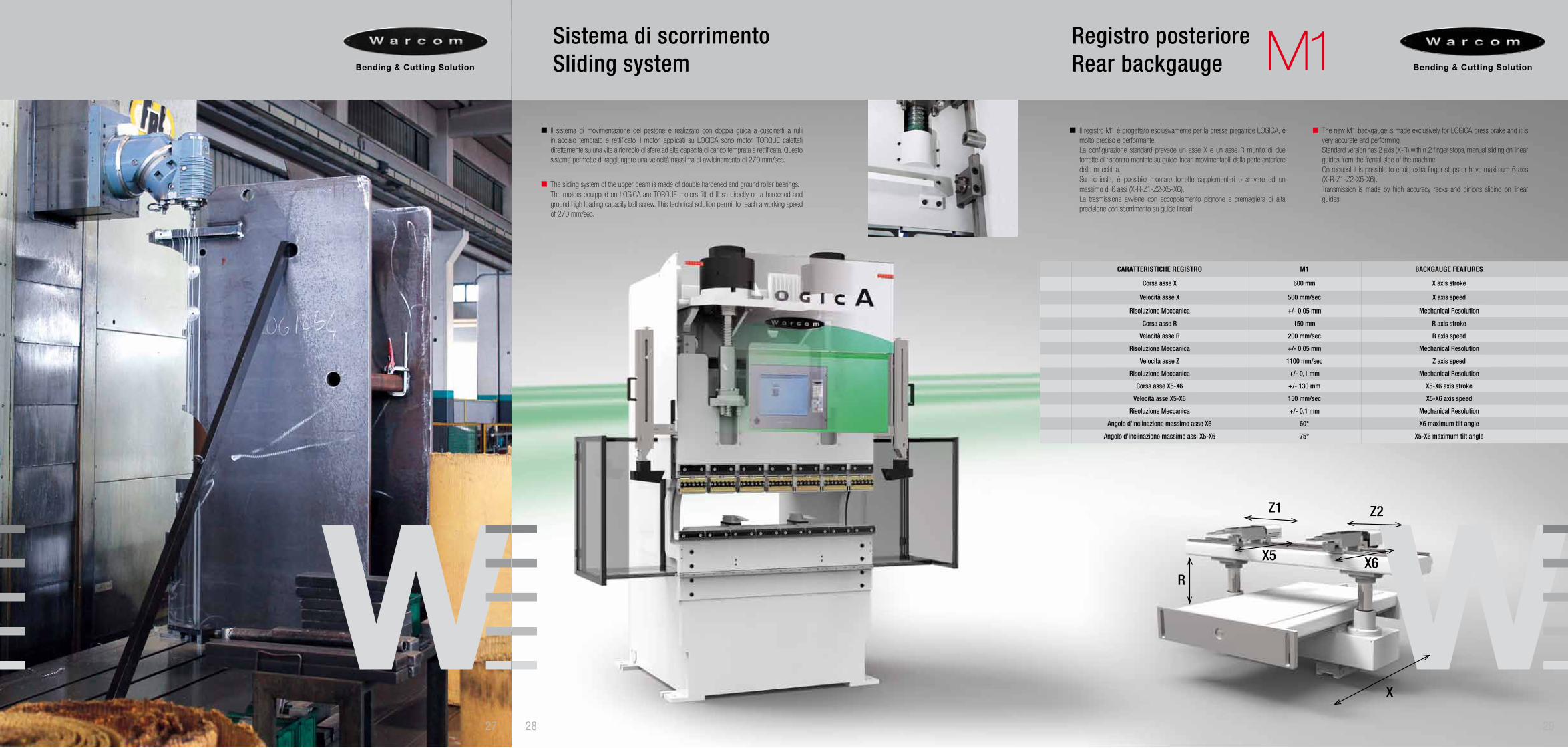
Il registro M1 è progettato esclusivamente per la pressa piegatrice LOGICA, è molto preciso e performante.La configurazione standard prevede un asse X e un asse R munito di due torrette di riscontro montate su guide lineari movimentabili dalla parte anteriore della macchina.Su richiesta, è possibile montare torrette supplementari o arrivare ad un massimo di 6 assi (X-R-Z1-Z2-X5-X6).La trasmissione avviene con accoppiamento pignone e cremagliera di alta precisione con scorrimento su guide lineari.
The new M1 backgauge is made exclusively for LOGICA press brake and it is very accurate and performing.Standard version has 2 axis (X-R) with n.2 finger stops, manual sliding on linear guides from the frontal side of the machine.On request it is possible to equip extra finger stops or have maximum 6 axis (X-R-Z1-Z2-X5-X6). Transmission is made by high accuracy racks and pinions sliding on linear guides.
CARATTERISTICHE REGISTRO M1 BACKGAUGE FEATURES
Corsa asse X 600 mm X axis stroke
Velocità asse X 500 mm/sec X axis speed
Risoluzione Meccanica +/- 0,05 mm Mechanical Resolution
Corsa asse R 150 mm R axis stroke
Velocità asse R 200 mm/sec R axis speed
Risoluzione Meccanica +/- 0,05 mm Mechanical Resolution
Velocità asse Z 1100 mm/sec Z axis speed
Risoluzione Meccanica +/- 0,1 mm Mechanical Resolution
Corsa asse X5-X6 +/- 130 mm X5-X6 axis stroke
Velocità asse X5-X6 150 mm/sec X5-X6 axis speed
Risoluzione Meccanica +/- 0,1 mm Mechanical Resolution
Angolo d’inclinazione massimo asse X6 60° X6 maximum tilt angle
Angolo d’inclinazione massimo assi X5-X6 75° X5-X6 maximum tilt angle
X6
X
Il sistema di movimentazione del pestone è realizzato con doppia guida a cuscinetti a rulli in acciaio temprato e rettificato. I motori applicati su LOGICA sono motori TORQUE calettati direttamente su una vite a ricircolo di sfere ad alta capacità di carico temprata e rettificata. Questo sistema permette di raggiungere una velocità massima di avvicinamento di 270 mm/sec.
The sliding system of the upper beam is made of double hardened and ground roller bearings.The motors equipped on LOGICA are TORQUE motors fitted flush directly on a hardened and ground high loading capacity ball screw. This technical solution permit to reach a working speed of 270 mm/sec.
Sistema di scorrimentoSliding system
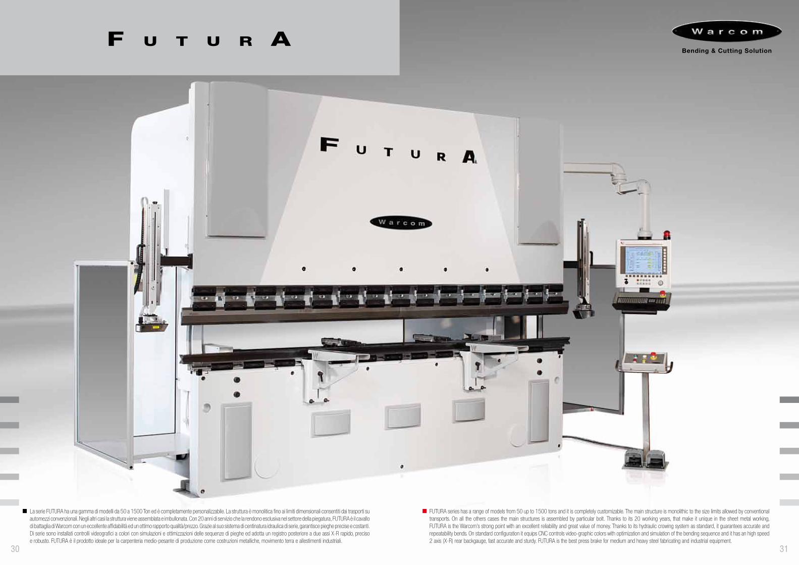
La serie FUTURA ha una gamma di modelli da 50 a 1500 Ton ed è completamente personalizzabile. La struttura è monolitica fino ai limiti dimensionali consentiti dai trasporti su automezzi convenzionali. Negli altri casi la struttura viene assemblata e imbullonata. Con 20 anni di servizio che la rendono esclusiva nel settore della piegatura, FUTURA è il cavallo di battaglia di Warcom con un eccellente affidabilità ed un ottimo rapporto qualità/prezzo. Grazie al suo sistema di centinatura idraulica di serie, garantisce pieghe precise e costanti. Di serie sono installati controlli videografici a colori con simulazioni e ottimizzazioni delle sequenze di pieghe ed adotta un registro posteriore a due assi X-R rapido, preciso e robusto. FUTURA è il prodotto ideale per la carpenteria medio-pesante di produzione come costruzioni metalliche, movimento terra e allestimenti industriali.
30
FUTURA series has a range of models from 50 up to 1500 tons and it is completely customizable. The main structure is monolithic to the size limits allowed by conventional transports. On all the others cases the main structures is assembled by particular bolt. Thanks to its 20 working years, that make it unique in the sheet metal working, FUTURA is the Warcom’s strong point with an excellent reliability and great value of money. Thanks to its hydraulic crowing system as standard, it guarantees accurate and repeatability bends. On standard configuration it equips CNC controls video-graphic colors with optimization and simulation of the bending sequence and it has an high speed 2 axis (X-R) rear backgauge, fast accurate and sturdy. FUTURA is the best press brake for medium and heavy steel fabricating and industrial equipment.
31
Centinatura idraulicaHydraulic crowning system
32
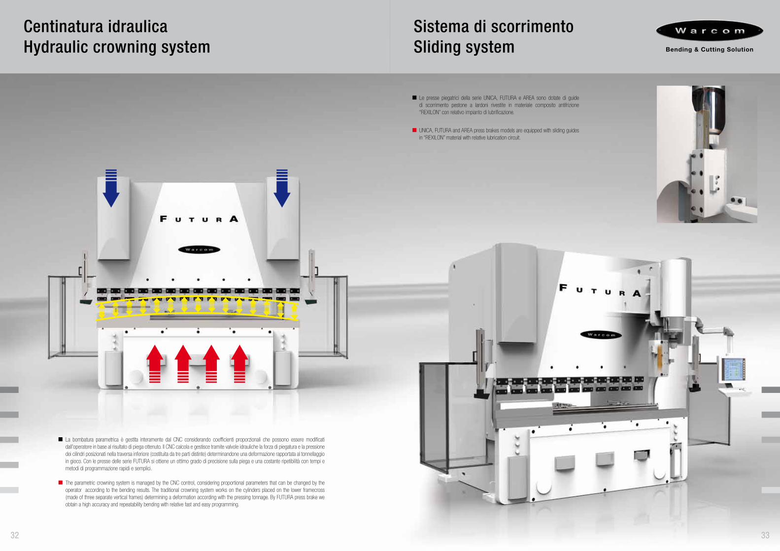
La bombatura parametrica è gestita interamente dal CNC considerando coefficienti proporzionali che possono essere modificati dall’operatore in base al risultato di piega ottenuto. Il CNC calcola e gestisce tramite valvole idrauliche la forza di piegatura e la pressione dei cilindri posizionati nella traversa inferiore (costituita da tre parti distinte) determinandone una deformazione rapportata al tonnellaggio in gioco. Con le presse delle serie FUTURA si ottiene un ottimo grado di precisione sulla piega e una costante ripetibilità con tempi e metodi di programmazione rapidi e semplici.
The parametric crowning system is managed by the CNC control, considering proportional parameters that can be changed by the operator according to the bending results. The traditional crowning system works on the cylinders placed on the lower framecross (made of three separate vertical frames) determining a deformation according with the pressing tonnage. By FUTURA press brake we obtain a high accuracy and repeatability bending with relative fast and easy programming.
Le presse piegatrici della serie UNICA, FUTURA e AREA sono dotate di guide di scorrimento pestone a lardoni rivestite in materiale composito antifrizione “REXILON” con relativo impianto di lubrificazione.
UNICA, FUTURA and AREA press brakes models are equipped with sliding guides in “REXILON” material with relative lubrication circuit.
Sistema di scorrimentoSliding system
33
3534
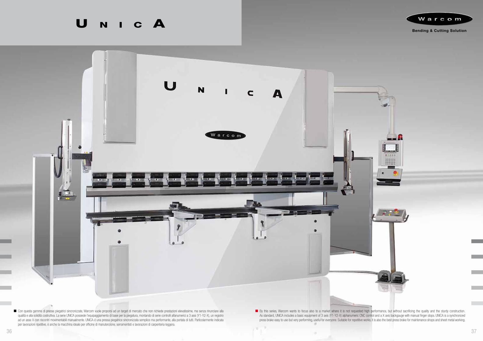
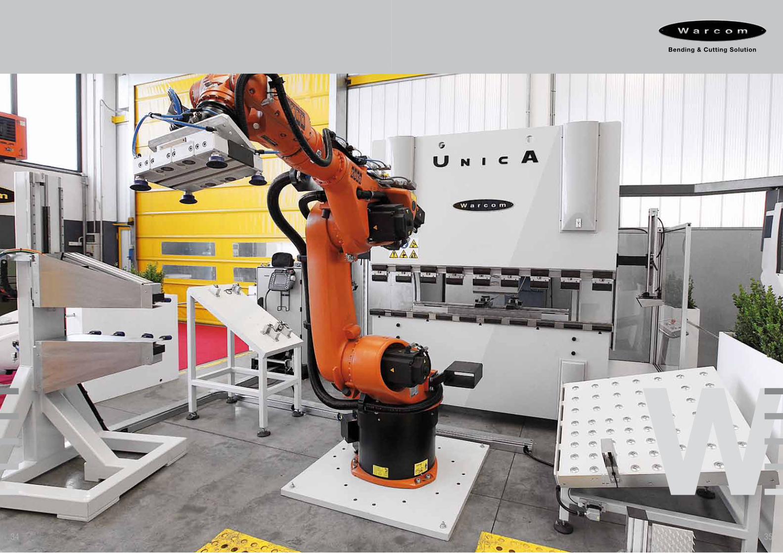
Con questa gamma di presse piegatrici sincronizzate, Warcom vuole proporsi ad un target di mercato che non richiede prestazioni elevatissime, ma senza rinunciare alla qualità e alla solidità costruttiva. La serie UNICA possiede l’equipaggiamento di base per la piegatura, montando di serie controlli alfanumerici a 3 assi (Y1-Y2-X), un registro ad un asse X con riscontri movimentabili manualmente. UNICA è una pressa piegatrice sincronizzata semplice ma performante, alla portata di tutti. Particolarmente indicata per lavorazioni ripetitive, è anche la macchina ideale per officine di manutenzione, serramentisti e lavorazioni di carpenteria leggera.
36
By this series, Warcom wants to focus also to a market where it is not requested high performance, but without sacrificing the quality and the sturdy construction.As standard, UNICA includes a basic equipment of 3 axis (Y1-Y2-X) alphanumeric CNC control and a X axis backgauge with manual finger stops. UNICA is a synchronized press brake easy to use but very performing, useful for everyone. Suitable for repetitive works, it is also the best press brake for maintenance shops and sheet metal working.
37
Sistema di scorrimentoSliding system
38
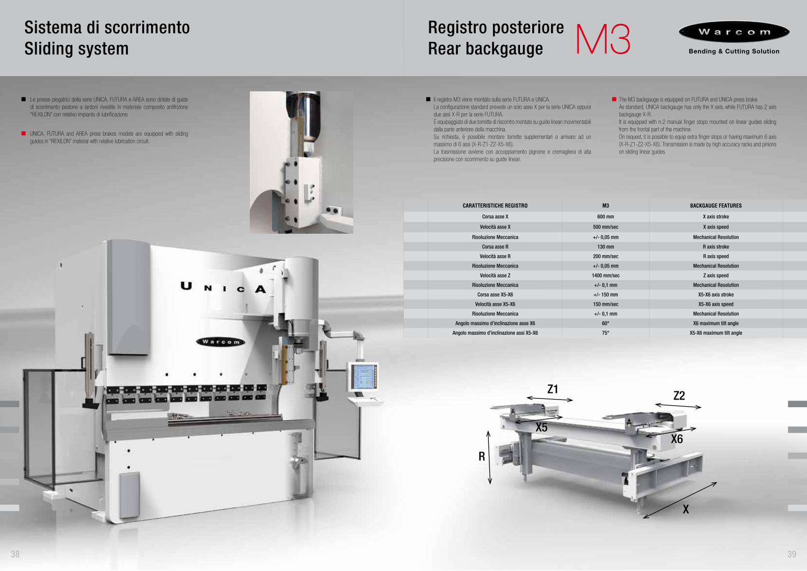
Le presse piegatrici della serie UNICA, FUTURA e AREA sono dotate di guide di scorrimento pestone a lardoni rivestite in materiale composito antifrizione “REXILON” con relativo impianto di lubrificazione.
UNICA, FUTURA and AREA press brakes models are equipped with sliding guides in “REXILON” material with relative lubrication circuit.
R
Z1 Z2
X5
39
Registro posteriore Rear backgauge M3
Il registro M3 viene montato sulla serie FUTURA e UNICA.La configurazione standard prevede un solo asse X per la serie UNICA oppure due assi X-R per la serie FUTURA. È equipaggiato di due torrette di riscontro montate su guide lineari movimentabili dalla parte anteriore della macchina.Su richiesta, è possibile montare torrette supplementari o arrivare ad un massimo di 6 assi (X-R-Z1-Z2-X5-X6).La trasmissione avviene con accoppiamento pignone e cremagliera di alta precisione con scorrimento su guide lineari.
The M3 backgauge is equipped on FUTURA and UNICA press brake. As standard, UNICA backgauge has only the X axis, while FUTURA has 2 axis backgauge X-R. It is equipped with n.2 manual finger stops mounted on linear guides sliding from the frontal part of the machine.On request, it is possible to equip extra finger stops or having maximum 6 axis (X-R-Z1-Z2-X5-X6). Transmission is made by high accuracy racks and pinions on sliding linear guides.
CARATTERISTICHE REGISTRO M3 BACKGAUGE FEATURES
Corsa asse X 600 mm X axis stroke
Velocità asse X 500 mm/sec X axis speed
Risoluzione Meccanica +/- 0,05 mm Mechanical Resolution
Corsa asse R 130 mm R axis stroke
Velocità asse R 200 mm/sec R axis speed
Risoluzione Meccanica +/- 0,05 mm Mechanical Resolution
Velocità asse Z 1400 mm/sec Z axis speed
Risoluzione Meccanica +/- 0,1 mm Mechanical Resolution
Corsa asse X5-X6 +/- 150 mm X5-X6 axis stroke
Velocità asse X5-X6 150 mm/sec X5-X6 axis speed
Risoluzione Meccanica +/- 0,1 mm Mechanical Resolution
Angolo massimo d’inclinazione asse X6 60° X6 maximum tilt angle
Angolo massimo d’inclinazione assi X5-X6 75° X5-X6 maximum tilt angle
X
X6
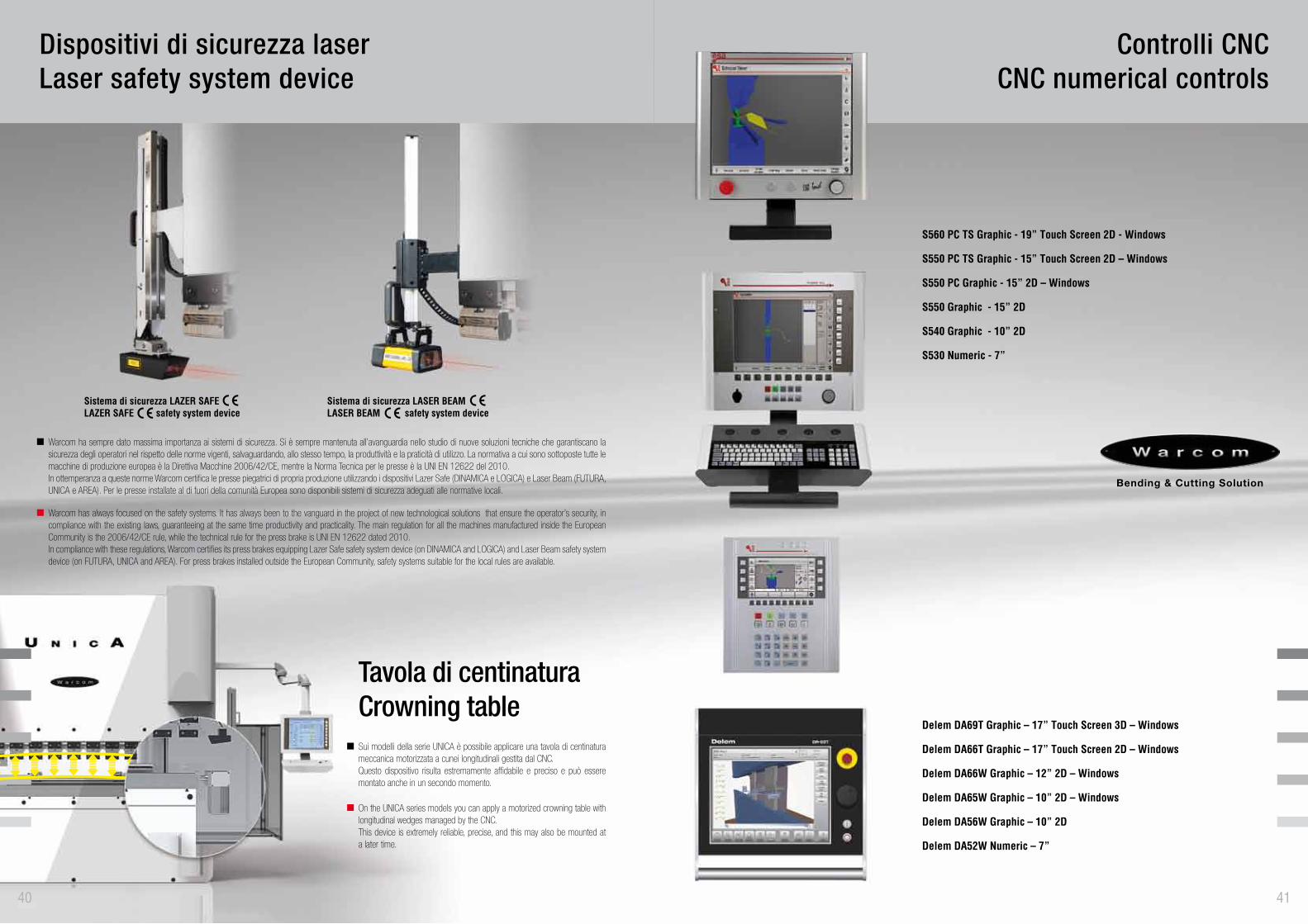
Warcom ha sempre dato massima importanza ai sistemi di sicurezza. Si è sempre mantenuta all’avanguardia nello studio di nuove soluzioni tecniche che garantiscano la sicurezza degli operatori nel rispetto delle norme vigenti, salvaguardando, allo stesso tempo, la produttività e la praticità di utilizzo. La normativa a cui sono sottoposte tutte le macchine di produzione europea è la Direttiva Macchine 2006/42/CE, mentre la Norma Tecnica per le presse è la UNI EN 12622 del 2010. In ottemperanza a queste norme Warcom certifica le presse piegatrici di propria produzione utilizzando i dispositivi Lazer Safe (DINAMICA e LOGICA) e Laser Beam (FUTURA, UNICA e AREA). Per le presse installate al di fuori della comunità Europea sono disponibili sistemi di sicurezza adeguati alle normative locali.
Warcom has always focused on the safety systems. It has always been to the vanguard in the project of new technological solutions that ensure the operator’s security, in compliance with the existing laws, guaranteeing at the same time productivity and practicality. The main regulation for all the machines manufactured inside the European Community is the 2006/42/CE rule, while the technical rule for the press brake is UNI EN 12622 dated 2010.In compliance with these regulations, Warcom certifies its press brakes equipping Lazer Safe safety system device (on DINAMICA and LOGICA) and Laser Beam safety system device (on FUTURA, UNICA and AREA). For press brakes installed outside the European Community, safety systems suitable for the local rules are available.
Dispositivi di sicurezza laser Laser safety system device
Tavola di centinaturaCrowning table
40
Sui modelli della serie UNICA è possibile applicare una tavola di centinatura meccanica motorizzata a cunei longitudinali gestita dal CNC.Questo dispositivo risulta estremamente affidabile e preciso e può essere montato anche in un secondo momento.
On the UNICA series models you can apply a motorized crowning table with longitudinal wedges managed by the CNC. This device is extremely reliable, precise, and this may also be mounted at a later time.
Sistema di sicurezza LAZER SAFELAZER SAFE safety system device
Sistema di sicurezza LASER BEAMLASER BEAM safety system device
S560 PC TS Graphic - 19” Touch Screen 2D - Windows
S550 PC TS Graphic - 15” Touch Screen 2D – Windows
S550 PC Graphic - 15” 2D – Windows
S550 Graphic - 15” 2D
S540 Graphic - 10” 2D
S530 Numeric - 7”
Delem DA69T Graphic – 17” Touch Screen 3D – Windows
Delem DA66T Graphic – 17” Touch Screen 2D – Windows
Delem DA66W Graphic – 12” 2D – Windows
Delem DA65W Graphic – 10” 2D – Windows
Delem DA56W Graphic – 10” 2D
Delem DA52W Numeric – 7”
Controlli CNCCNC numerical controls
41
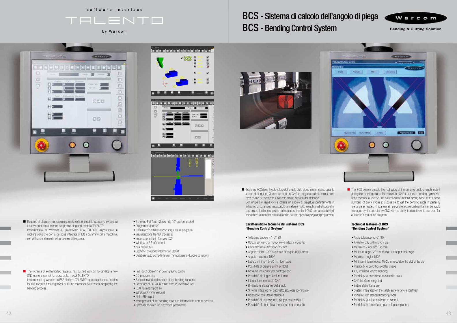
Esigenze di piegatura sempre più complesse hanno spinto Warcom a sviluppare il nuovo controllo numerico per presse piegatrici modello TALENTO.Implementato da Warcom su piattaforma ESA, TALENTO rappresenta la migliore soluzione per la gestione integrata di tutti i parametri della macchina, semplificando al massimo il processo di piegatura.
The increase of sophisticated requests has pushed Warcom to develop a new CNC numeric control for press brake model TALENTO. Implemented by Warcom on ESA platform, TALENTO represents the best solution for the integrated management of all the machines parameters, simplifying the bending process.
• Schermo Full Touch Screen da 19’’ grafico a colori• Programmazione 2D• Simulatore e ottimizzazione sequenza di piegatura• Visualizzazione file 3D processati• Importazione file in formato .DXF • Windows XP Professional• N.4 porte USB• Gestione posizione intermedi e utensili• Database auto compilante per memorizzare sviluppi e correzioni
• Full Touch Screen 19” color graphic control• 2D programming • Simulation and optimization of the bending sequence• Possibility of 3D visualization from PC software files.• .DXF format import file• Windows XP Professional • N.4 USB output• Management of the bending tools and intermediate clamps position.• Database to store the correction parameters.
42
Il sistema BCS rileva il reale valore dell’angolo della piega in ogni istante durante la fase di piegatura. Questo permette al CNC di eseguire cicli di pressata con brevi risalite per scaricare il naturale ritorno elastico del materiale. Con un paio di rapidi cicli si ottiene un angolo di piegatura perfettamente in tolleranza ai paramenti impostati. È un sistema molto semplice ed efficace che può essere facilmente gestito dall’operatore tramite il CNC con la possibilità di selezionare la modalità di utilizzo anche per una specifica piega del programma.
The BCS system detects the real value of the bending angle at each instant during the bending phase. This allows the CNC to execute bending cycles with short ascents to release the natural elastic material spring back. With a short numbers of quick cycles it is possible to get the bending angle in perfectly tolerance as request. It is a very simple and effective system that can be easily managed by the operator by CNC with the ability to select how to use even for a specific bend of the program.
Caratteristiche tecniche del sistema BCS“Bending Control System”
• Tolleranze angolo +/- 0°.30’
• Utilizzo esclusivo di monocave di altezza indistinta.
• Cava massima utilizzabile: 35 mm
• Angolo minimo: 20° superiore all’angolo del punzone
• Angolo massimo: 150°
• Labbro minimo 15-20 mm fuori cava
• Possibilità di piegare profili scatolati
• Nessuna limitazione per contropieghe
• Possibilità di piegare lamiere forate
• Integrazione interfaccia CNC
• Rivelazione istantanea dell’angolo
• Sistema integrato nel pacchetto sicurezza (certificato)
• Utilizzabile con utensili standard
• Possibilità di selezionare le pieghe da controllare
• Possibilità di controllo a campione programmabile
BCS - Sistema di calcolo dell’angolo di piega BCS - Bending Control System
Technical features of BCS “Bending Control System”
• Angle tolerance +/-0°.30’
• Available only with mono V dies
• Maximum V opening: 35 mm
• Minimum angle: 20° more than the upper tool angle
• Maximum angle: 150°
• Minimum internal edge: 15-20 mm outside the slot of the die
• Possibility to bend box profiles shape
• Any limitation for pre-bending
• Possibility to bend sheet metals with holes
• CNC interface integrated
• Instant detection angle
• System integrated on the safety system device (certified)
• Available with standard bending tools
• Possibility to select the bend to control
• Possibility to control a programming sample test
43
WES - Warcom Energy Saver
44
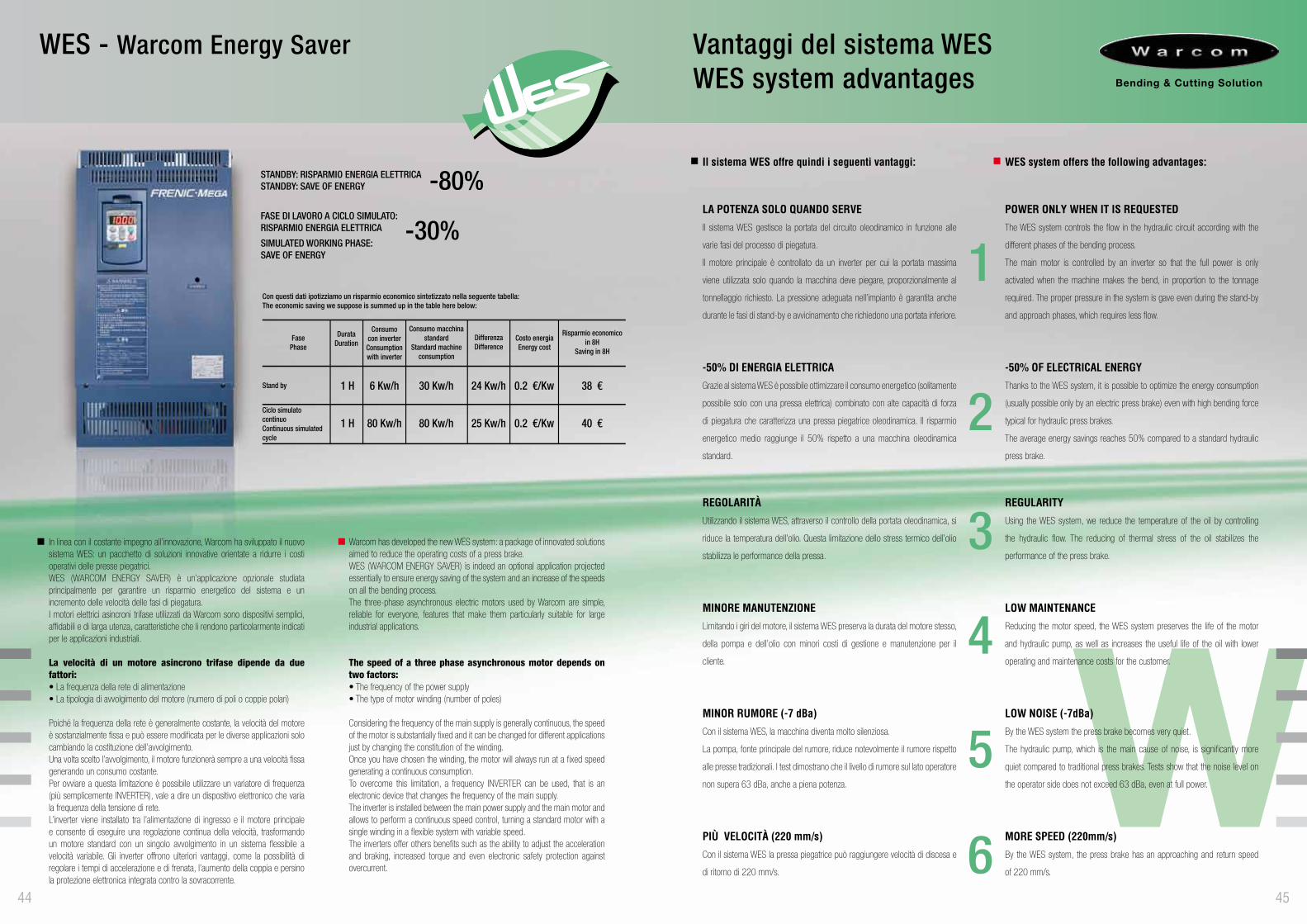
In linea con il costante impegno all’innovazione, Warcom ha sviluppato il nuovo sistema WES: un pacchetto di soluzioni innovative orientate a ridurre i costi operativi delle presse piegatrici.WES (WARCOM ENERGY SAVER) è un’applicazione opzionale studiata principalmente per garantire un risparmio energetico del sistema e un incremento delle velocità delle fasi di piegatura.I motori elettrici asincroni trifase utilizzati da Warcom sono dispositivi semplici, affidabili e di larga utenza, caratteristiche che li rendono particolarmente indicati per le applicazioni industriali.
La velocità di un motore asincrono trifase dipende da due fattori:• La frequenza della rete di alimentazione• La tipologia di avvolgimento del motore (numero di poli o coppie polari)
Poiché la frequenza della rete è generalmente costante, la velocità del motore è sostanzialmente fissa e può essere modificata per le diverse applicazioni solo cambiando la costituzione dell’avvolgimento.Una volta scelto l’avvolgimento, il motore funzionerà sempre a una velocità fissa generando un consumo costante. Per ovviare a questa limitazione è possibile utilizzare un variatore di frequenza (più semplicemente INVERTER), vale a dire un dispositivo elettronico che varia la frequenza della tensione di rete. L’inverter viene installato tra l’alimentazione di ingresso e il motore principale e consente di eseguire una regolazione continua della velocità, trasformando un motore standard con un singolo avvolgimento in un sistema flessibile a velocità variabile. Gli inverter offrono ulteriori vantaggi, come la possibilità di regolare i tempi di accelerazione e di frenata, l’aumento della coppia e persino la protezione elettronica integrata contro la sovracorrente.
Warcom has developed the new WES system: a package of innovated solutions aimed to reduce the operating costs of a press brake. WES (WARCOM ENERGY SAVER) is indeed an optional application projected essentially to ensure energy saving of the system and an increase of the speeds on all the bending process.The three-phase asynchronous electric motors used by Warcom are simple, reliable for everyone, features that make them particularly suitable for large industrial applications.
The speed of a three phase asynchronous motor depends on two factors:• The frequency of the power supply• The type of motor winding (number of poles)
Considering the frequency of the main supply is generally continuous, the speed of the motor is substantially fixed and it can be changed for different applications just by changing the constitution of the winding.Once you have chosen the winding, the motor will always run at a fixed speed generating a continuous consumption. To overcome this limitation, a frequency INVERTER can be used, that is an electronic device that changes the frequency of the main supply. The inverter is installed between the main power supply and the main motor and allows to perform a continuous speed control, turning a standard motor with a single winding in a flexible system with variable speed.The inverters offer others benefits such as the ability to adjust the acceleration and braking, increased torque and even electronic safety protection against overcurrent.
Vantaggi del sistema WESWES system advantages
1
2
3
4
5
645
Il sistema WES offre quindi i seguenti vantaggi:
LA POTENZA SOLO QUANDO SERVEIl sistema WES gestisce la portata del circuito oleodinamico in funzione alle
varie fasi del processo di piegatura.
Il motore principale è controllato da un inverter per cui la portata massima
viene utilizzata solo quando la macchina deve piegare, proporzionalmente al
tonnellaggio richiesto. La pressione adeguata nell’impianto è garantita anche
durante le fasi di stand-by e avvicinamento che richiedono una portata inferiore.
-50% DI ENERGIA ELETTRICAGrazie al sistema WES è possibile ottimizzare il consumo energetico (solitamente
possibile solo con una pressa elettrica) combinato con alte capacità di forza
di piegatura che caratterizza una pressa piegatrice oleodinamica. Il risparmio
energetico medio raggiunge il 50% rispetto a una macchina oleodinamica
standard.
REGOLARITÀUtilizzando il sistema WES, attraverso il controllo della portata oleodinamica, si
riduce la temperatura dell’olio. Questa limitazione dello stress termico dell’olio
stabilizza le performance della pressa.
MINORE MANUTENZIONELimitando i giri del motore, il sistema WES preserva la durata del motore stesso,
della pompa e dell’olio con minori costi di gestione e manutenzione per il
cliente.
MINOR RUMORE (-7 dBa)Con il sistema WES, la macchina diventa molto silenziosa.
La pompa, fonte principale del rumore, riduce notevolmente il rumore rispetto
alle presse tradizionali. I test dimostrano che il livello di rumore sul lato operatore
non supera 63 dBa, anche a piena potenza.
PIÙ VELOCITÀ (220 mm/s)Con il sistema WES la pressa piegatrice può raggiungere velocità di discesa e
di ritorno di 220 mm/s.
WES system offers the following advantages:
POWER ONLY WHEN IT IS REQUESTEDThe WES system controls the flow in the hydraulic circuit according with the
different phases of the bending process.
The main motor is controlled by an inverter so that the full power is only
activated when the machine makes the bend, in proportion to the tonnage
required. The proper pressure in the system is gave even during the stand-by
and approach phases, which requires less flow.
-50% OF ELECTRICAL ENERGYThanks to the WES system, it is possible to optimize the energy consumption
(usually possible only by an electric press brake) even with high bending force
typical for hydraulic press brakes.
The average energy savings reaches 50% compared to a standard hydraulic
press brake.
REGULARITYUsing the WES system, we reduce the temperature of the oil by controlling
the hydraulic flow. The reducing of thermal stress of the oil stabilizes the
performance of the press brake.
LOW MAINTENANCEReducing the motor speed, the WES system preserves the life of the motor
and hydraulic pump, as well as increases the useful life of the oil with lower
operating and maintenance costs for the customer.
LOW NOISE (-7dBa)By the WES system the press brake becomes very quiet.
The hydraulic pump, which is the main cause of noise, is significantly more
quiet compared to traditional press brakes. Tests show that the noise level on
the operator side does not exceed 63 dBa, even at full power.
MORE SPEED (220mm/s)By the WES system, the press brake has an approaching and return speed
of 220 mm/s.
1 H 6 Kw/h 30 Kw/h 24 Kw/h 0.2 €/Kw 38 €Stand by
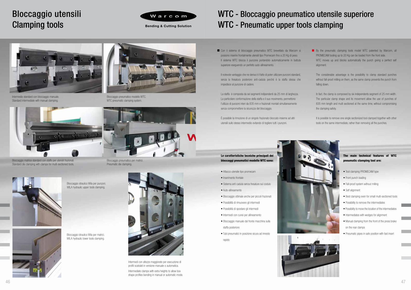
Intermedio standard con bloccaggio manuale.Standard intermediate with manual clamping.
Bloccaggio idraulico Wila per punzoni.WILA hydraulic upper tools clamping.
Bloccaggio matrice standard con staffe per utensili frazionati.Standard die clamping with clamps for multi-sectioned tools.
Bloccaggio idraulico Wila per matrici.WILA hydraulic lower tools clamping.
Intermedi con altezze maggiorate per esecuzione di profili scatolati in versione manuale o automatica.
Intermediate clamps with extra heights to allow box shape profiles bending in manual or automatic mode.
Bloccaggio pneumatico modello WTC.WTC pneumatic clamping system.
Bloccaggio pneumatico per matrici.Pneumatic die clamping.
Bloccaggio utensiliClamping tools
46
Con il sistema di bloccaggio pneumatico WTC brevettato da Warcom si
possono inserire frontalmente utensili tipo Promecam fino a 20 Kg di peso.
Il sistema WTC blocca il punzone portandolo automaticamente in battuta
superiore eseguendo un perfetto auto-allineamento.
Il notevole vantaggio che ne deriva è il fatto di poter utilizzare punzoni standard,
senza la fresatura posteriore anti-caduta perché è la staffa stessa che
impedisce al punzone di cadere.
La staffa è composta da sei segmenti indipendenti da 25 mm di larghezza.
La particolare conformazione della staffa e il suo movimento, permettono
l’utilizzo di punzoni interi da 835 mm e frazionati montati simultaneamente
senza compromettere la sicurezza del bloccaggio.
È possibile la rimozione di un singolo frazionato bloccato insieme ad altri
utensili sullo stesso intermedio evitando di togliere tutti i punzoni.
Le caratteristiche tecniche principali dei
bloccaggi pneumatici modello WTC sono:
• Attacco utensile tipo promecam
• Inserimento frontale
• Sistema anti caduta senza fresature sul codulo
• Auto-allineamento
• Bloccaggio ottimale anche per piccoli frazionati
• Possibilità di rimuovere gli intermedi
• Possibilità di spostare gli intermedi
• Intermedi con cunei per allineamento
• Bloccaggio manuale dal fronte macchina sulla
staffa posteriore
• Tubi pneumatici in posizione sicura ad innesto
rapido
WTC - Bloccaggio pneumatico utensile superioreWTC - Pneumatic upper tools clamping
47
By the pneumatic clamping tools model WTC patented by Warcom, all
PROMECAM tooling up to 20 Kg can be loaded from the front side.
WTC moves up and blocks automatically the punch giving a perfect self
alignment.
The considerable advantage is the possibility to clamp standard punches
without fall-proof milling on them, as the same clamp prevents the punch from
falling down.
In fact, the clamp is composed by six independents segment of 25 mm width.
The particular clamp shape and its movement allow the use of punches of
835 mm length and multi sectioned at the same time, without compromising
the clamping safety.
It is possible to remove one single sectionized tool clamped together with other
tools on the same intermediate, rather than removing all the punches.
The main technical features of WTC
pneumatic clamping tool are:
• Tool clamping PROMECAM type
• Front punch loading
• Fall-proof system without milling
• Self alignment
• Best clamping even for small multi-sectioned tools
• Possibility to remove the intermediates
• Possibility to move the location of the intermediates
• Intermediates with wedges for alignment
• Manual clamping from the front of the press brake
on the rear clamps
• Pneumatic pipes in safe position with fast insert
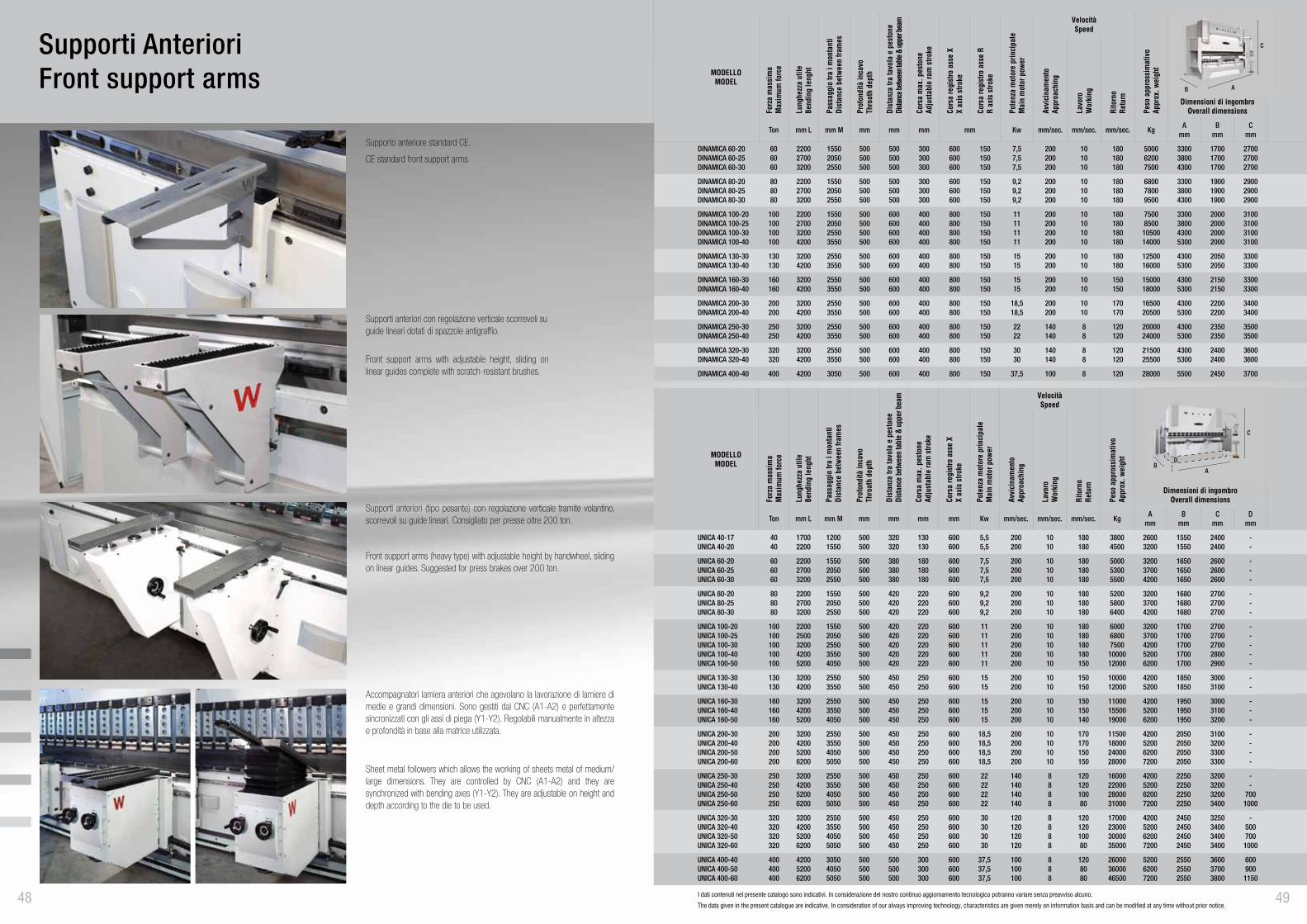
Supporto anteriore standard CE.
Supporti anteriori con regolazione verticale scorrevoli suguide lineari dotati di spazzole antigraffio.
Front support arms with adjustable height, sliding on linear guides complete with scratch-resistant brushes.
Supporti anteriori (tipo pesante) con regolazione verticale tramite volantino, scorrevoli su guide lineari. Consigliato per presse oltre 200 ton.
Front support arms (heavy type) with adjustable height by handwheel, sliding on linear guides. Suggested for press brakes over 200 ton.
Accompagnatori lamiera anteriori che agevolano la lavorazione di lamiere di medie e grandi dimensioni. Sono gestiti dal CNC (A1-A2) e perfettamente sincronizzati con gli assi di piega (Y1-Y2). Regolabili manualmente in altezza e profondità in base alla matrice utilizzata.
Sheet metal followers which allows the working of sheets metal of medium/large dimensions. They are controlled by CNC (A1-A2) and they are synchronized with bending axes (Y1-Y2). They are adjustable on height and depth according to the die to be used.
CE standard front support arms.
Supporti AnterioriFront support arms
48
MODELLOMODEL
Forz
a m
assi
ma
Max
imum
forc
e
Lung
hezz
a ut
ileBe
ndin
g le
nght
Pass
aggi
o tra
i m
onta
nti
Dist
ance
bet
ween
fram
es
Prof
ondi
tà in
cavo
Thro
ath
dept
h
Dist
anza
tra
tavo
la e
pes
tone
Dista
nce
betw
een
tabl
e &
uppe
r bea
m
Cors
a m
ax. p
esto
neAd
just
able
ram
stro
ke
Cors
a re
gist
ro a
sse
XX
axis
stro
ke
Pote
nza
mot
ore
prin
cipa
leM
ain
mot
or p
ower
VelocitàSpeed
Peso
app
ross
imat
ivo
Appr
ox. w
eigh
t
Dimensioni di ingombroOverall dimensionsAv
vici
nam
ento
Appr
oach
ing
Lavo
roW
orki
ng
Rito
rno
Retu
rn
Ton mm L mm M mm mm mm mm Kw mm/sec. mm/sec. mm/sec. KgA
mmB
mmC
mmD
mm
UNICA 40-17UNICA 40-20
4040
17002200
12001550
500500
320320
130130
600600
5,55,5
200200
1010
180180
38004500
26003200
15501550
24002400
--
UNICA 60-20UNICA 60-25UNICA 60-30
606060
220027003200
155020502550
500500500
380380380
180180180
600600600
7,57,57,5
200200200
101010
180180180
500053005500
320037004200
165016501650
260026002600
---
UNICA 80-20UNICA 80-25UNICA 80-30
808080
220027003200
155020502550
500500500
420420420
220220220
600600600
9,29,29,2
200200200
101010
180180180
520058006400
320037004200
168016801680
270027002700
---
UNICA 100-20UNICA 100-25UNICA 100-30UNICA 100-40UNICA 100-50
100100100100100
22002500320042005200
15502050255035504050
500500500500500
420420420420420
220220220220220
600600600600600
1111111111
200200200200200
1010101010
180180180180150
600068007500
1000012000
32003700420052006200
17001700170017001700
27002700270028002900
-----
UNICA 130-30UNICA 130-40
130130
32004200
25503550
500500
450450
250250
600600
1515
200200
1010
150150
1000012000
42005200
18501850
30003100
--
UNICA 160-30UNICA 160-40UNICA 160-50
160160160
320042005200
255035504050
500500500
450450450
250250250
600600600
151515
200200200
101010
150150140
110001550019000
420052006200
195019501950
300031003200
---
UNICA 200-30UNICA 200-40UNICA 200-50UNICA 200-60
200200200200
3200420052006200
2550355040505050
500500500500
450450450450
250250250250
600600600600
18,518,518,518,5
200200200200
10101010
170170150150
11500180002400028000
4200520062007200
2050205020502050
3100320033003300
----
UNICA 250-30UNICA 250-40UNICA 250-50UNICA 250-60
250250250250
3200420052006200
2550355040505050
500500500500
450450450450
250250250250
600600600600
22222222
140140140140
8888
12012010080
16000220002800031000
4200520062007200
2250225022502250
3200320032003400
--
7001000
UNICA 320-30UNICA 320-40UNICA 320-50UNICA 320-60
320320320320
3200420052006200
2550355040505050
500500500500
450450450450
250250250250
600600600600
30303030
120120120120
8888
12012010080
17000230003000035000
4200520062007200
2450245024502450
3250340034003400
-500700
1000
UNICA 400-40UNICA 400-50UNICA 400-60
400400400
420052006200
305040505050
500500500
500500500
300300300
600600600
37,537,537,5
100100100
888
1208080
260003600046500
520062007200
255025502550
360037003800
600900
1150
C
AB
D
I dati contenuti nel presente catalogo sono indicativi. In considerazione del nostro continuo aggiornamento tecnologico potranno variare senza preavviso alcuno.
The data given in the present catalogue are indicative. In consideration of our always improving technology, characteristics are given merely on information basis and can be modified at any time without prior notice.49
MODELLOMODEL
Forz
a m
assi
ma
Max
imum
forc
e
Lung
hezz
a ut
ileBe
ndin
g le
nght
Pass
aggi
o tra
i m
onta
nti
Dist
ance
bet
ween
fram
es
Prof
ondi
tà in
cavo
Thro
ath
dept
h
Dist
anza
tra
tavo
la e
pes
tone
Dista
nce b
etwee
n tab
le &
uppe
r bea
m
Cors
a m
ax. p
esto
neAd
just
able
ram
stro
ke
Cors
a re
gist
ro a
sse
XX
axis
stro
ke
Cors
a re
gist
ro a
sse
RR
axis
stro
ke
Pote
nza
mot
ore
prin
cipa
leM
ain
mot
or p
ower
VelocitàSpeed
Peso
app
ross
imat
ivo
Appr
ox. w
eigh
t
Dimensioni di ingombroOverall dimensionsAv
vici
nam
ento
Appr
oach
ing
Lavo
roW
orki
ng
Rito
rno
Retu
rn
Ton mm L mm M mm mm mm mm Kw mm/sec. mm/sec. mm/sec. KgA
mmB
mmC
mm
DINAMICA 60-20DINAMICA 60-25DINAMICA 60-30
606060
220027003200
155020502550
500500500
500500500
300300300
600600600
150150150
7,57,57,5
200200200
101010
180180180
500062007500
330038004300
170017001700
270027002700
DINAMICA 80-20DINAMICA 80-25DINAMICA 80-30
808080
220027003200
155020502550
500500500
500500500
300300300
600600600
150150150
9,29,29,2
200200200
101010
180180180
680078009500
330038004300
190019001900
290029002900
DINAMICA 100-20DINAMICA 100-25DINAMICA 100-30DINAMICA 100-40
100100100100
2200270032004200
1550205025503550
500500500500
600600600600
400400400400
800800800800
150150150150
11111111
200200200200
10101010
180180180180
75008500
1050014000
3300380043005300
2000200020002000
3100310031003100
DINAMICA 130-30DINAMICA 130-40
130130
32004200
25503550
500500
600600
400400
800800
150150
1515
200200
1010
180180
1250016000
43005300
20502050
33003300
DINAMICA 160-30DINAMICA 160-40
160160
32004200
25503550
500500
600600
400400
800800
150150
1515
200200
1010
150150
1500018000
43005300
21502150
33003300
DINAMICA 200-30DINAMICA 200-40
200200
32004200
25503550
500500
600600
400400
800800
150150
18,518,5
200200
1010
170170
1650020500
43005300
22002200
34003400
DINAMICA 250-30DINAMICA 250-40
250250
32004200
25503550
500500
600600
400400
800800
150150
2222
140140
88
120120
2000024000
43005300
23502350
35003500
DINAMICA 320-30DINAMICA 320-40
320320
32004200
25503550
500500
600600
400400
800800
150150
3030
140140
88
120120
2150025500
43005300
24002400
36003600
DINAMICA 400-40 400 4200 3050 500 600 400 800 150 37,5 100 8 120 28000 5500 2450 3700
C
AB
5150
MODELLOMODEL
Forz
a m
assi
ma
Max
imum
forc
e
Lung
hezz
a ut
ileBe
ndin
g le
nght
Pass
aggi
o tra
i m
onta
nti
Dist
ance
bet
ween
fram
es
Prof
ondi
tà in
cavo
Thro
ath
dept
h
Dist
anza
tra
tavo
la e
pes
tone
Dista
nce b
etwee
n tab
le &
uppe
r bea
m
Cors
a m
ax. p
esto
neAd
just
able
ram
stro
ke
Cors
a re
gist
ro a
sse
XX
axis
stro
ke
Cors
a re
gist
ro a
sse
RR
axis
stro
ke
Pote
nza
mot
ore
prin
cipa
leM
ain
mot
or p
ower
VelocitàSpeed
Peso
app
ross
imat
ivo
Appr
ox. w
eigh
t
Dimensioni di ingombroOverall dimensionsAv
vici
nam
ento
Appr
oach
ing
Lavo
roW
orki
ng
Rito
rno
Retu
rn
Ton mm L mm M mm mm mm mm Kw mm/sec. mm/sec. mm/sec. KgA
mmB
mmC
mmD
mm
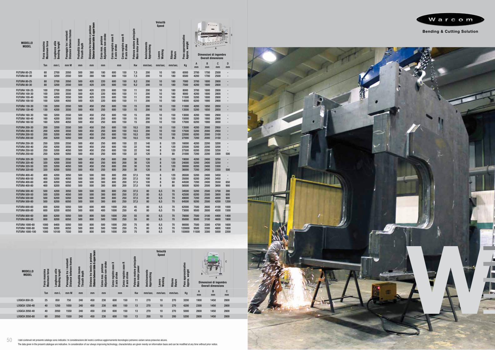
FUTURA 60-25FUTURA 60-30
6060
27003200
20502550
500500
380380
180180
600600
150150
7,57,5
200200
1010
180180
60006500
37004200
17001700
25002500
--
FUTURA 80-25FUTURA 80-30
8080
27003200
20502550
500500
420420
220220
600600
150150
9,29,2
200200
1010
180180
70007500
37004200
18001800
28002800
--
FUTURA 100-25FUTURA 100-30FUTURA 100-40FUTURA 100-50
100100100100
2700320042005200
2550355035504050
500500500500
420420420420
220220220220
600600600600
150150150150
11111111
200200200200
10101010
180180180180
80009000
1150014000
3700420052006200
1800180018001900
2800280028002900
----
FUTURA 130-30FUTURA 130-40
130130
32004200
25503550
500500
450450
250250
600600
150150
1515
200200
1010
150150
1100013500
42005200
18501850
28502850
--
FUTURA 160-30FUTURA 160-40FUTURA 160-50
160160160
320042005200
255035504050
500500500
450450450
250250250
600600600
150150150
151515
200200200
101010
150150150
130001500017000
420052006200
190019001900
290029003000
---
FUTURA 200-30FUTURA 200-40FUTURA 200-50FUTURA 200-60
200200200200
3200420052006200
2550355040505050
500500500500
450450450450
250250250250
600600600600
150150150150
18,518,518,518,5
200200200150
10101010
15015015095
13500175002200027000
4200520062007200
2000200020002000
2950295031003150
----
FUTURA 250-30FUTURA 250-40FUTURA 250-50FUTURA 250-60
250250250250
3200420052006200
2550355040505050
500500500500
450450450450
250250250250
600600600600
150150150150
22222222
140140140120
8888
12012012080
16000225002750031000
4200520062007200
2200220022002200
3200320032503300
---
500
FUTURA 320-30FUTURA 320-40FUTURA 320-50FUTURA 320-60
320320320320
3200420052006200
2550355040505050
500500500500
450450450450
250250250250
600600600600
200200200200
30303030
120120120120
8888
12012012080
19000240003000036000
4200520062007200
2400240024002400
3250325033003350
---
500
FUTURA 400-40FUTURA 400-50FUTURA 400-60FUTURA 400-80
400400400400
4200520062008200
3050405050506050
500500500500
500500500500
300300300300
800800800800
200200200200
37,537,537,537,5
100100100100
8888
1201208080
26500350004450056500
5200620072009200
2400240024002500
3450345035503600
--
650900
FUTURA 500-40FUTURA 500-50FUTURA 500-60FUTURA 500-80
500500500500
4200520062008200
3050405050506050
500500500500
500500500500
300300300300
800800800800
250250250250
37,537,537,537,5
80808080
6,56,56,56,5
70707070
34500425004900064500
5200620072009200
2500250025002500
3700380040004200
300600900
1200
FUTURA 600-60FUTURA 600-80
600600
62008200
50506050
500500
600600
400400
10001000
250250
4545
8080
6,56,5
7070
6200073000
75009500
26002600
41004500
10001500
FUTURA 800-60FUTURA 800-80
800800
62008200
50506050
500500
800800
500500
10001000
250250
5555
8080
6,56,5
7070
7800095000
75009500
31003100
44004600
14001800
FUTURA 1000-60FUTURA 1000-80FUTURA 1000-100
100010001000
6400820010100
505060507550
500500500
800800800
500500500
100010001000
250250250
757575
808080
6,56,56,5
707070
90000120000150000
75009500
11500
330033003300
470048005000
160018002200
C
AB
D
MODELLOMODEL
Forz
a m
assi
ma
Max
imum
forc
e
Lung
hezz
a ut
ileBe
ndin
g le
nght
Pass
aggi
o tra
i m
onta
nti
Dist
ance
bet
ween
fram
es
Prof
ondi
tà in
cavo
Thro
ath
dept
h
Dist
anza
tra
tavo
la e
pes
tone
Dista
nce b
etwee
n tab
le &
uppe
r bea
m
Cors
a m
ax. p
esto
neAd
just
able
ram
stro
ke
Cors
a re
gist
ro a
sse
XX
axis
stro
ke
Cors
a re
gist
ro a
sse
RR
axis
stro
ke
Pote
nza
mot
ore
prin
cipa
leM
ain
mot
or p
ower
VelocitàSpeed
Peso
app
ross
imat
ivo
Appr
ox. w
eigh
t
Dimensioni di ingombroOverall dimensionsAv
vici
nam
ento
Appr
oach
ing
Lavo
roW
orki
ng
Rito
rno
Retu
rn
Ton mm L mm M mm mm mm mm Kw mm/sec. mm/sec. mm/sec. KgA
mmB
mmC
mm
LOGICA 850-25 25 850 750 240 450 230 600 150 11 270 10 270 3200 1900 1450 2800
LOGICA 1250-40 40 1250 1050 240 450 230 600 150 13 270 10 270 4200 2300 1450 2800
LOGICA 2050-40 40 2050 1550 240 450 230 600 150 13 270 10 270 5000 2800 1450 2800
LOGICA 2050-60 60 2050 1550 240 450 230 600 150 13 200 10 200 5200 2800 1450 2800
C
A
B
I dati contenuti nel presente catalogo sono indicativi. In considerazione del nostro continuo aggiornamento tecnologico potranno variare senza preavviso alcuno.
The data given in the present catalogue are indicative. In consideration of our always improving technology, characteristics are given merely on information basis and can be modified at any time without prior notice.
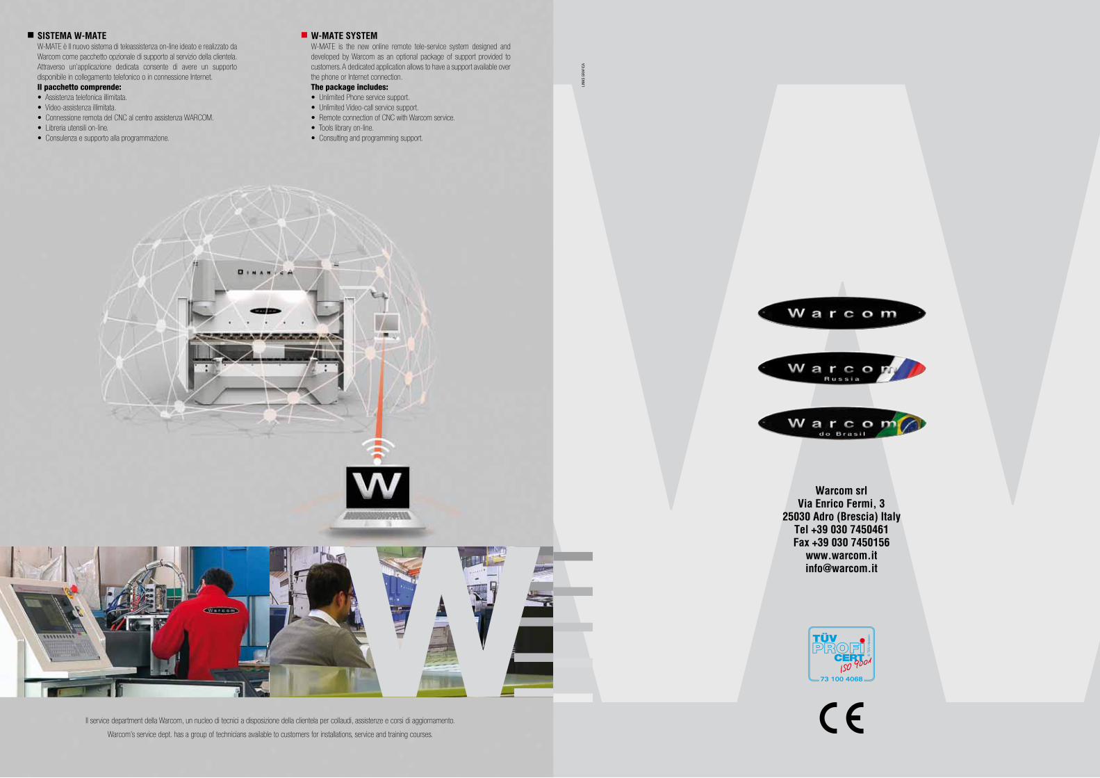
W-MATE SYSTEMW-MATE is the new online remote tele-service system designed and developed by Warcom as an optional package of support provided to customers. A dedicated application allows to have a support available over the phone or Internet connection. The package includes: • Unlimited Phone service support.• Unlimited Video-call service support.• Remote connection of CNC with Warcom service.• Tools library on-line.• Consulting and programming support.
SISTEMA W-MATEW-MATE è Il nuovo sistema di teleassistenza on-line ideato e realizzato da Warcom come pacchetto opzionale di supporto al servizio della clientela. Attraverso un’applicazione dedicata consente di avere un supporto disponibile in collegamento telefonico o in connessione Internet. Il pacchetto comprende:• Assistenza telefonica illimitata.• Video-assistenza illimitata.• Connessione remota del CNC al centro assistenza WARCOM.• Libreria utensili on-line.• Consulenza e supporto alla programmazione.