VM PVC-C - rohrleitungssysteme.de · VM PVC-C 194 I dati del presente prospetto sono forniti in...
12
Valvola a membrana Diaphragm valve Vanne à membrane Membranventil VM PVC-C
Transcript of VM PVC-C - rohrleitungssysteme.de · VM PVC-C 194 I dati del presente prospetto sono forniti in...

Valvola a membranaDiaphragm valveVanne à membraneMembranventil
VM PVC-C
VM PVC-C
194
I dati del presente prospetto sono forniti in buona fede. La FIP non si assume alcu-na responsabilità su quei dati non diret-tamente derivati da norme internazionali. La FIP si riserva di apportarvi qualsiasi modifica.
L’installazione e la manutenzione del pro-dotto deve essere eseguita da personale qualificato.
The data given in this leaflet are offered in good faith. No liability can be accepted concerning technical data that are not directly covered by reco-gnized interna-tional standards. FIP reserves the right to carry out any modification to the products shown in this Ieaflet.
Installation and maintenance operations should be made by professionals.
Les données contenues dans cette brochure sont fournies en bonne foi. FIP n’assume aucune responsabilité pour les données qui ne dérivent pas directement des normes internationa-les. FIP garde le droit d’apporter toute modification aux produits présentés dans cette brochure.
L’installation et la manutention doivent être effectuées par du personnel qualifié.
Alle Daten dieser Druckschrift wurden nach bestem Wissen angegeben, jedoch besteht keine Verbindlichkeit, sofern sie nicht direkt internationalen Normen entnommen wurden. Die Än-derung von Maßen oder Ausführungen bleibt FIP vorbehalten.
Installations und Wartungsarbeiten dürfennur von Fachleuten vorgenommen werden.

VM PVC-C
195
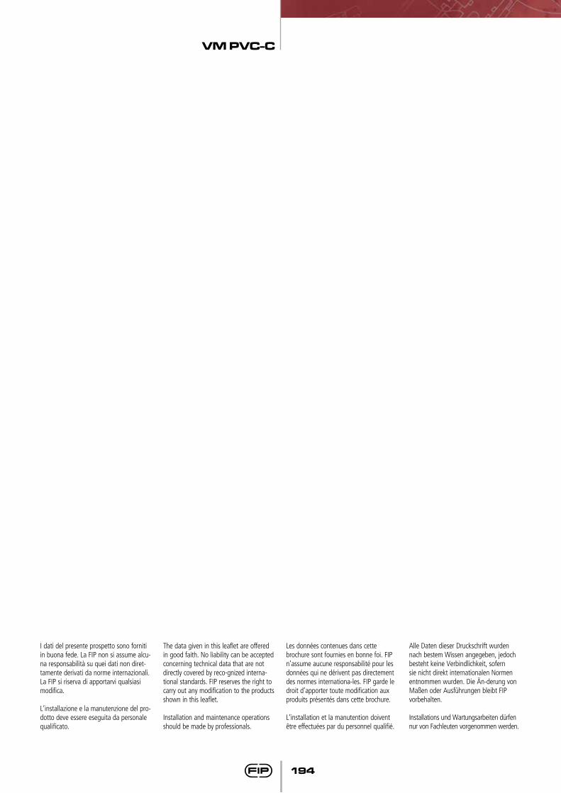
La VM è una valvola a membrana a comando manuale, con volantino non saliente, ovvero che mantiene sempre la stessa altezza durante la rotazione.Gli organi di manovra interni, isolati dal fluido, sono in metallo, con cuscinetto in POM per ridurre al minimo l’attrito.Il prolungamento in plastica dello stelo indica la posizione della valvola.Le viti che fissano il coperchio al corpo valvola sono inserite dal basso, e si avvitano su bussole affogate nel coperchio stesso, evitando in tal modo la presenza sulla superficie esterna di cavità che possono essere depositi di sporcizia o impurità.La valvola a membrana, molto sem-plice nel funzionamento e di costru-zione compatta e robusta, può essere impiegata con fluidi liquidi o gassosi, ed è particolarmente adatta per fluidi abrasivi o contenenti impurità.L’innovativo sistema di tenuta CDSA - Circular Diaphragm Sealing Area - utilizzato fino al DN50, offre, inoltre, i seguenti vantaggi:- distribuzione uniforme della pressio-
ne dell’otturatore sulla membrana di tenuta
- diminuzione fino al 20% della cop-pia di serraggio delle viti che fissa-no il corpo valvola all’attuatore
- minore stress meccanico per tutti i componenti della valvola (attuatore, corpo e membrana)
- facilità di pulizia delle zone interne della valvola
- minimizzazione del rischio di accu-mulo di depositi, contaminazione o danneggiamento della membrana a causa di fenomeni di cristalliz-zazione
- riduzione della coppia di manovra fino al 40%
PECULIARITà:• Elevato coefficiente di flusso e
ridotte perdite di carico.• Costruzione compatta e massa
contenuta.• Modularità della gamma: solo 5
grandezze di membrane e coperchi per 9 diverse misure di valvola.
• Facile sostituzione della membrana di tenuta.
• Indicatore di posizione fornito di serie.
ACCESSORI:• dispositivo di bloccaggio di sicu-
rezza• indicatore elettrico di posizione (1
microinterruttore)• Piastra per allineare tutti i corpi da
DN 15 a DN 50 sulla stessa linea di centro tubo.
Per maggiori informazioni visitare il sito: www.fipnet.it
The VM type diaphragm valve is ma-nually operated by a non-rising hand-wheel. That means it does not chan-ge his height during the rotation.Metal spindle and sleeve ensure total reliability. The compression bearing made of POM reduces friction and consequent wear.The plastic spindle extension in-dicates the valve position.The valve design is compact and sturdy. The hand-wheel has been designed without spokes, to provide increased strength.Threaded inserts are moulded-in into the bonnet, thus eliminating the need to drill holes, and also allowing the body fixing bolts to be inserted from the bottom.The above method allows a cavi-ties-free bonnet, avoiding dirt and impurities accumulation.The diaphragm valve can be used with liquid and gaseous fluids, and is particularly suitable for dirty or abrasive media.The innovative CDSA - Circular Diaphragm Sealing Area - system (up to DN50) offers the following mecha-nical advantages: - uniform distribution of the pressure
made by the compressor on the sealing diaphragm
- up to 20% of bolt tightening tor-que reduction
- reduced mechanical stress on all valve components (actuator,body and diaphragm)
- easy internal cleaning- lower risk of deposit accumulation,
fluid contamination and damaging of the diaphragm due to the even-tual crystallization
- reduction of the closing handwheel torque of the manual valves up to 40%
CHARACTERISTICS:• High Kv value and reduced pressu-
re losses.• Compact and sturdy construction,
low weight.• Modular range: only 5 diaphragms
and bonnet sizes for 9 different body sizes.
• Easy replacement of the sealing diaphragm.
• Position indicator as standard.
ACCESSORIES:• Security blocking device.• Electrical position indicator (1 microswitch)• Plate for DN 15-50 bodies ali-
gnment at the same pipe center-line.
For more information please visit our website: www.fipnet.it
La vanne a membrane type VM est une vanne à commande manuelle qui ne demande pas d’entretien. Pendant les operations de fermeture et ouverture le volant reste toujours a la meme hauteur. La tige est en metal. Le joint de compression est en POM pour réduire au minimum le frottement. Le prolongement de la ti-ge indique si la vanne est ouverte ou fermée. Le volant assure une extrème stabilité. Les mamelons taraudés sont moulés directement sur la partie su-perieur de la vanne. Les vis de fixage du couvercle au corps de la vanne sont positionnees de facon qui soit evité le depôt de saulure. L’avantage de la vanne à membrane par rapport aux autres types de robinets est sa semplicité de fonctionnement et sa construction compacte. Cet type de vanne permét de travailler avec des fluides soit liquides que gazeux. La vanne à membrane est particuliere-ment indiquée dans le cas de liquides abrasifs ou avec des suspensions solides.Le nouveau système CDSA - Circular Diaphragm Sealing Area - utilisé jusqu’au DN50, offre les avantages suivantes:- distribution uniforme de la préssion
du compresseur sur la membrane.- réduction jusqu’au 20% de la
coupple de serrage des écrous qui fixent le corps de la vanne à son actuateur
- réduit stress mécanique pour tous les composants de la vanne (actua-teur, corps et membrane)
- simple nettoyage des parties inter-nes du corps de la vanne
- réduction du risque d’accumulation de dépôts, de contamination où de causer des dégâts à la membrane par cristallisation
- réduction de la coupple de serrage jusqu’au 40%
CARACTERISTIQUES• Peu de perte de pression• Construction compacte et robuste,
vanne moins lourdes• 5 dimensions de membrane pour 9
diametres nominaux• Facile remplacement de la mem-
brane• indicateur de position
ACCESSOIRES:• Blocage manuelle de secours• Indicateur electrique de position (1
microinterrupteur)• Plaque de fixation pour l’alligne-
ment de l’axe de centre-tube de vanne DN 15-50
For more information please visit our website: www.fipnet.it
Das Membranventil ist mit einer wartungsfreien Handbetätigung über ein nicht steigendes Handrad ausgerüstet. Die POM Drucklager des Antriebes reduzieren die Reibung auf ein Minimum. Eine Spindelverlängerung dient als optische Stellungsanzeige fur die “Auf Zu” Positionen. Das speichenlose Handrad und das glattflachige Oberteil verhindern Schmutzablagerungen.Die Anschlußstutzen des kompakten Gehäuses erlauben die Ausrustung mit allen gängigen Anschlußteillen, wie Fittings, Verschraubungen oder Losflanschen.Das Membranventil wird vorzugs weise fur flüssige Medien eingesetzt, die aggressiv, abrasiv, ver schmutzt sein können.Durch die verschiedenen Gehäuse und Membranwerkstoffe wird ein breiter Anwendungsbereich ermög-licht. Das innovative CDSA-Design -Kreisrundes Membran Dichtsystem (bis DN 50) bietet folgende mechani-schen Vorteile:- Optimale Druckverteilung über das
Druckstück auf die abdichtende Membran
- bis zu 20% Reduzierung der Anzugsdrehmomente
- geringere Belastung aller Ventilkomponenten (Antrieb, Ventilkörper und Dichtmembran)
- einfache und effiziente interne Reinigung
- deutlich geringeres Risiko der Ansammlung von Feststoffen und Auskristallisationen, dadurch werden Rekontaminationen und Beschädigung der Membrane reduziert
- Reduzierung der notwendigen Schließkräfte bei handbetätigten Ventilen um bis zu 40%
HAUPTMERKMALE• Geringer Druckverlust bei hoher
Durchflußleistung.• Robuste und kompakte Bau form,
geringes Gewicht.• Baukastenprinzip: nur 5 Membran-
bzw. Oberteil-abmessungen für 9 verschiedene Ventilnennweiten.
• Das Ventil ist wartungsfreundlich.• optische Stellungsanzeige.
ZUBEHÖR• Schließbegrenzung• Electromechanische
Stellungsanzeige (1 Microschalter)• Distanzplatte: die Nennweiten von
15 bis 50 mm sind so konzipiert, daß die Mittelachsen der Gehäuse mit nur einer Ausgleichsplatte ni-veaugleich sind.
Für weitere Details schauen Sie auf unsere Website: www.fipnet.it
Valvola a membrana
Diaphragm valve
Vanne àmembrane
Membranventil
VM PVC-C
196
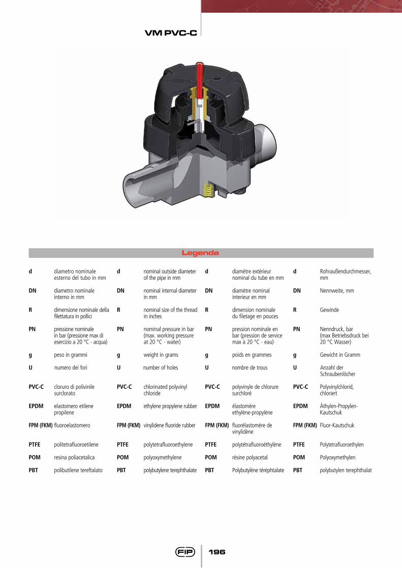
Legenda
d diametro nominale esterno del tubo in mm
DN diametro nominale interno in mm
R dimensione nominale della filettatura in pollici
PN pressione nominale in bar (pressione max di esercizio a 20 °C - acqua)
g peso in grammi
U numero dei fori
PVC-C cloruro di polivinile surclorato
EPDM elastomero etilene propilene
FPM (FKM) fluoroelastomero
PTFE politetrafluoroetilene
POM resina poliacetalica
PBT polibutilene tereftalato
d nominal outside diameter of the pipe in mm
DN nominal internal diameter in mm
R nominal size of the thread in inches
PN nominal pressure in bar (max. working pressure at 20 °C - water)
g weight in grams
U number of holes
PVC-C chlorinated polyvinyl chloride
EPDM ethylene propylene rubber
FPM (FKM) vinylidene fluoride rubber
PTFE polytetrafluoroethylene
POM polyoxymethylene
PBT polybutylene terephthalate
d diamètre extérieur nominal du tube en mm
DN diamètre nominal interieur en mm
R dimension nominale du filetage en pouces
PN pression nominale en bar (pression de service max à 20 °C - eau)
g poids en grammes
U nombre de trous
PVC-C polyvinyle de chlorure surchloré
EPDM élastomère ethylène-propylène
FPM (FKM) fluorélastomère de vinylidène
PTFE polytétrafluoroéthylène
POM résine polyacetal
PBT Polybutylène téréphtalate
d Rohraußendurchmesser, mm
DN Nennweite, mm
R Gewinde
PN Nenndruck, bar (max Betriebsdruck bei
20 °C Wasser)
g Gewicht in Gramm
U Anzahl der Schraubenlöcher
PVC-C Polyvinylchlorid, chloriert
EPDM Äthylen-Propylen- Kautschuk
FPM (FKM) Fluor-Kautschuk
PTFE Polytetrafluoroethylen
POM Polyoxymethylen
PBT polybutylen terephthalat
VM PVC-C
197
Dati Tecnici
Technical Data
Données Techniques
Technische Daten
1
3
1
3
2
2
bar
16
14
12
10
8
6
4
2
0
-20 0 20 40 °C60 10080
pres
sione
di e
serc
izio
- wor
king
pre
ssur
epr
essio
n de
ser
vice
- Bet
riebs
tdru
ck
temperatura di esercizio - working temperaturetempérature de service - Betriebstemperatur
bar
1
0,1
0,01
0,001
DN 15
DN 25
DN 32
DN 40
100 l/min1000 10000101
DN 50
DN 65
DN 20
DN 80
DN 10
0
perd
ita d
i car
ico -
pres
sure
lost
- pe
rte d
e ch
arge
- Dr
uckv
erlu
stportata - flow rate- débit - Durchflußmenge
32300
25175
20136
1593
DNkv100
40416
50766
651300
1002700
802000
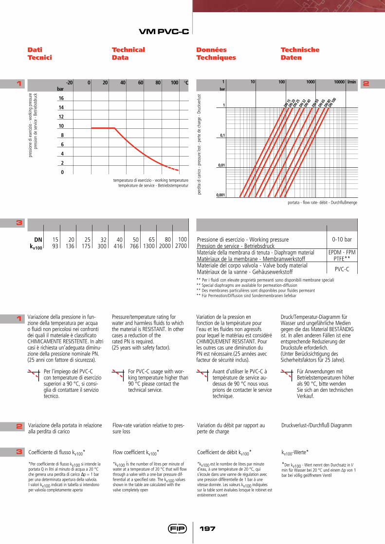
0-10 bar
EPDM - FPM PTFE**
PVC-C
Pressione di esercizio - Working pressurePression de service - BetriebsdruckMateriale della membrana di tenuta - Diaphragm materialMatèriaux de la membrane - MembranwerkstoffMateriale del corpo valvola - Valve body materialMatèriaux de la vanne - Gehäusewerkstoff** Per i fluidi con elevate proprietà permeanti sono disponibili membrane speciali** Special diaphragms are available for permeation-diffusion** Des membranes particulières sont disponibles pour fluides permeant** Für Permeation/Diffusion sind Sondermembranen liefebar
Variazione della portata in relazione alla perdita di carico
Flow-rate variation relative to pres-sure loss
Variation du débit par rapport au perte de charge
Druckverlust-/Durchfluß Diagramm
Per l’impiego del PVC-C con temperature di esercizio superiori a 90 °C, si consi-glia di contattare il servizio tecnico.
For PVC-C usage with wor-king temperature higher than 90 °C please contact the technical service.
Avant d’utiliser le PVC-C à température de service au-dessus de 90 °C nous vous prions de contacter le service technique.
Für Anwendungen mit Betriebstemperaturen höher als 90 °C, bitte wenden Sie sich an den technischen Verkauf.
Coefficiente di flusso kv100* *Per coefficiente di flusso kv100 si intende la portata Q in litri al minuto di acqua a 20 °C che genera una perdita di carico ∆p = 1 bar per una determinata apertura della valvola.I valori kv100 indicati in tabella si intendono per valvola completamente aperta
Flow coefficient kv100*
*kv100 is the number of litres per minute of water at a temperature of 20 °C that will flow through a valve with a one-bar pressure dif-ferential at a specified rate. The kv100 values shown in the table are calculated with the valve completely open
Coefficient de débit kv100*
*kv100 est le nombre de litres par minute d’eau, à une température de 20 °C, qui s’écoule dans une vanne de régulation avec une pression différentielle de 1 bar à une vitesse donnée. Les valeurs kv100 indiquées sur la table sont évaluées lorsque le robinet est entièrement ouvert
kv100-Werte*
*Der kv100 - Wert nennt den Durchsatz in I/min für Wasser bei 20 °C und einem ∆p von 1 bar bei völlig geöffnetem Ventil
Variazione della pressione in fun-zione della temperatura per acqua o fluidi non pericolosi nei confronti dei quali il materiale è classificato CHIMICAMENTE RESISTENTE. In altri casi è richiesta un’adeguata diminu-zione della pressione nominale PN. (25 anni con fattore di sicurezza).
Pressure/temperature rating forwater and harmless fluids to which the material is RESISTANT. In other cases a reduction of therated PN is required.(25 years with safety factor).
Variation de la pression enfonction de la température pourl’eau et les fluides non agressifspour lequel le matériau est considéré CHIMIQUEMENT RESISTANT. Pour les outres cas une diminution du PN est nécessaire.(25 années avec facteur de sécurité inclus).
Druck/Temperatur-Diagramm fürWasser und ungefährliche Mediengegen die das Material BESTÄNDIG ist. In allen anderen Fällen ist eineentsprechende Reduzierung derDruckstufe erforderlich.(Unter Berücksichtigung des Sicherheitsfaktors für 25 Jahre).

VM PVC-C
198
Dimensioni Dimensions Dimensions Dimensionen
La valvola a membrana FIP è di-sponibile nelle seguenti versioni, i cui attacchi sono in accordo con le seguenti norme:Incollaggio: EN ISO 15493, ASTM F439, accoppiabili con tubi secondoEN ISO 15493, DIN 8079-8080, ASTM F 441.Filettatura:ASTM D 2464, ISO 228-1, DIN 2999Flangiatura: DIN 2501, EN ISO 15493, ISO 7005-1, ANSI B16.5 cl. 150.
La vanne à membrane FIP est dispo-nibile dans les suivantes versions, dont les embouts sont conformes aux normes suivantes:Encollage: EN ISO 15493, ASTM F439, assemblés avec des tubes selon EN ISO 15493, DIN 8079-8080, ASTM F 441.Filetage: ASTM D 2464, ISO 228-1, DIN 2999Brides: DIN 2501, EN ISO 15493, ISO 7005-1, ANSI B16.5 cl. 150.
Die FIP Membranventile entsprechen mit ihren Anschluß-Möglichkeiten folgenden Normen:Klebeanschluß: EN ISO 15493, ASTM F439, fürRohre nach EN ISO 15493, DIN 8079-8080, ASTM F 441.Gewindeverbindung: ASTM D 2464, ISO 228-1, DIN 2999Flanschanschluß: DIN 2501, EN ISO 15493, ISO 7005-1, ANSI B16.5 cl. 150.
The FIP diaphragm valve is available in the following versions, whose couplings comply with the following standards: Solvent welding: EN ISO 15493, ASTM F439, coupling to pipes complying with EN ISO 15493, DIN 8079-8080, ASTM F 441.Threaded couplings ASTM D 2464, ISO 228-1, DIN 2999Flanged couplings: DIN 2501, EN ISO 15493, ISO 7005-1, ANSI B16.5 cl. 150.
VMDCVALVOLA A MEMBRANAcon attacchi maschio per incollaggio, serie metrica
DIAPHRAGM VALVEwith metric series spigot ends for solvent welding
VANNE à MEMBRANEavec embouts mâle à coller, série metrique
MEMBRANVENTILmit Klebestutzen23.885.0...
d
2025324050637590
110
PN
101010101010
*10*10*10
DN
1520253240506580
100
B
959595
126126148225225295
B1
262626404040555569
H
124144154174194224284300340
h
121212181818232323
H1
909090
115115140200200250
L
161922263138445161
J
M6M6M6M8M8M8
M12M12M12
I
252525
44,544,544,5100100120
g
720720720
15601560250072607260
10860
VMUICVALVOLA A MEMBRANAcon attacchi a bocchettone femmina per incollaggio
DIAPHRAGM VALVEwith unionised metric series plain female ends for solvent welding
VANNE à MEMBRANEavec raccordement union femelles à coller
MEMBRANVENTILVerschraubung mit Klebemuffen23.885.5...
d
202532405063
B1
262626404040
DN
152025324050
PN
101010101010
B
959595
126126148
H
147154168192222266
h
121212161616
H1
909090
115115140
I
252525
44,544,544,5
LA
108108116134154184
J
M6M6M6M8M8M8
Z
115116124140160190
E
415058727998
R1
1”1 1/4”1 1/2”
2”2 1/4”2 3/4”
g
860895930
172018002915
*PTFE PN6

VM PVC-C
199
VMUFCVALVOLA A MEMBRANAcon attacchi a bocchettone femmina, filettatura cilindrica gas
DIAPHRAGM VALVEwith unionised BS parallel threaded female ends
VANNE à MEMBRANEavec raccordement union filetage cylindrique gaz
MEMBRANVENTILVerschraubung mit Innengewinde
R
1/2” 3/4”
1” 1 1/4” 1 1/2”
2”
B1
262626404040
DN
152025324050
PN
101010101010
B
959595
126126148
H
148151165188208246
h
121212161616
H1
909090
115115140
I
252525
44,544,544,5
LA
108108116134154184
J
M6M6M6M8M8M8
Z
118118127145165195
E
415058727998
R1
1”11/4”11/2”
2”21/4”23/4”
g
860895930
172018002915
VMUACVALVOLA A MEMBRANAcon attacchi a bocchettone femmina per incollaggio serie ASTM
DIAPHRAGM VALVEwith unionised ASTM series plain female ends for solvent welding
VANNE à MEMBRANEavec raccordement union femelles à coller série ASTM
MEMBRANVENTILVerschraubung mit ASTM Klebemuffen
d
1/2”3/4”
1”1 1/4”1 1/2”
2”
B1
262626404040
DN
152025324050
PN
101010101010
B
959595
126126148
H
160167180208234272
h
121212161616
H1
909090
115115140
I
252525
44,544,544,5
LA
108108116134154184
J
M6M6M6M8M8M8
Z
115115122144164195
E
415058727998
R1
1”11/4”11/2”
2”21/4”23/4”
g
860895930
172018002915
VMOC
d
2025324050637590
110
DN
1520253240506580
100
B
959595
126126148225225295
PN
101010101010
*10*10*10
B1
262626404040555569
H
130150160180200230290310350
H1
909090
115115140200200250
I
252525
44,544,544,5100100120
U
444444488
Sp
1113,5
1414161621
21,522,5
f
141414181818181818
J
M6M6M6M8M8M8
M12M12M12
F
657585
100110125145160180
g
910970
106021202225332085009150
13200
*PTFE PN6
VALVOLA A MEMBRANAcon flange fisse foratura EN/ISO/DIN PN10/16.Scartamento secondo EN 558-1.
DIAPHRAGM VALVEwith EN/ISO/DIN PN10/16.fixed flanges. Face to face according to EN 558-1.
VANNE à MEMBRANEavec brides fixes EN/ISO/DIN PN10/16.Longueur hors-tout EN 558-1.
MEMBRANVENTILmit Festflanschen, nach EN/ISO/DIN PN10/16. Baulange nach EN 558-1 und DIN 3441 Teil 2.21.885.09..
VM PVC-C
200
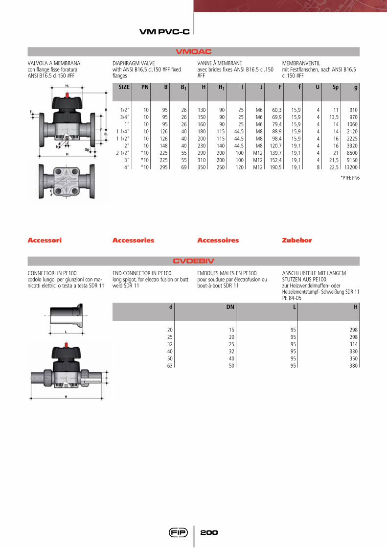
VMOAC
SIZE
1/2”3/4”
1”1 1/4”1 1/2”
2”2 1/2”
3”4”
PN
101010101010
*10*10*10
B1
262626404040555569
B
959595
126126148225225295
H
130150160180200230290310350
H1
909090
115115140200200250
I
252525
44,544,544,5100100120
J
M6M6M6M8M8M8
M12M12M12
U
444444448
F
60,369,979,488,998,4
120,7139,7152,4190,5
f
15,915,915,915,915,919,119,119,119,1
g
910970
106021202225332085009150
13200
Accessori Accessories Accessoires Zubehor
CVDEBIV
CONNETTORI IN PE100codolo lungo, per giunzioni con ma-nicotti elettrici o testa a testa SDR 11
END CONNECTOR IN PE100long spigot, for electro fusion or butt weld SDR 11
EMBOUTS MALES EN PE100pour soudure par électrofusion oubout-à-bout SDR 11
ANSCHLUßTEILE MIT LANGEM STUTZEN AUS PE100zur Heizwendelmuffen- oderHeizelementstumpf- Schweißung SDR 11PE 84-05
d
202532405063
DN
152025324050
L
959595959595
H
298298314330350380
*PTFE PN6
VALVOLA A MEMBRANAcon flange fisse foratura ANSI B16.5 cl.150 #FF
DIAPHRAGM VALVEwith ANSI B16.5 cl.150 #FF fixed flanges
VANNE à MEMBRANEavec brides fixes ANSI B16.5 cl.150 #FF
MEMBRANVENTILmit Festflanschen, nach ANSI B16.5 cl.150 #FF
Sp
1113,5
1414161621
21,522,5
VM PVC-C
201
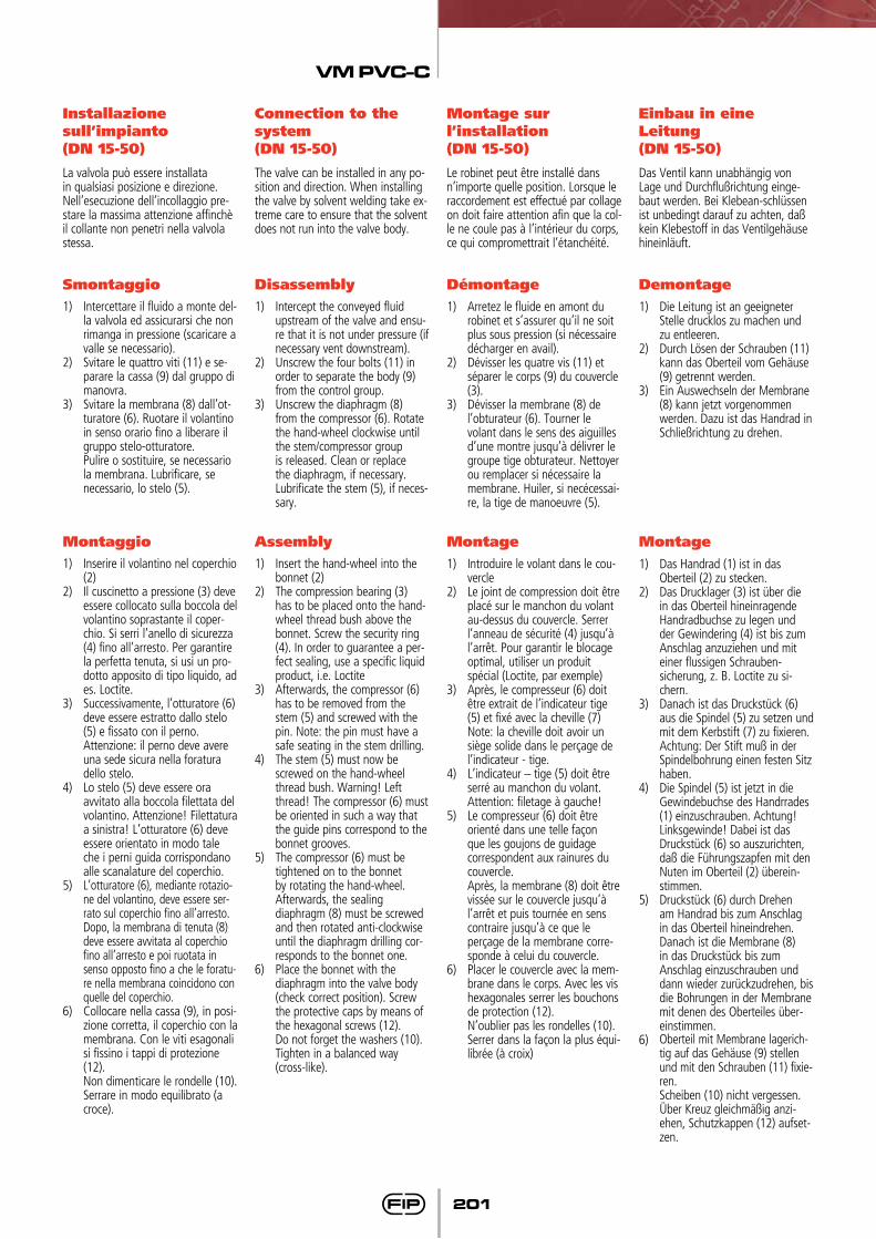
Installazione sull’impianto(DN 15-50)
Connection to the system(DN 15-50)
Montage sur l’installation(DN 15-50)
Einbau in eine Leitung(DN 15-50)
La valvola può essere installata in qualsiasi posizione e direzione. Nell’esecuzione dell’incollaggio pre-stare la massima attenzione affinchè il collante non penetri nella valvola stessa.
The valve can be installed in any po-sition and direction. When installing the valve by solvent welding take ex-treme care to ensure that the solvent does not run into the valve body.
Le robinet peut être installé dans n’importe quelle position. Lorsque le raccordement est effectué par collage on doit faire attention afin que la col-le ne coule pas à l’intérieur du corps, ce qui compromettrait l’étanchéité.
Das Ventil kann unabhängig von Lage und Durchflußrichtung einge-baut werden. Bei Klebean-schlüssen ist unbedingt darauf zu achten, daß kein Klebestoff in das Ventilgehäuse hineinläuft.
Smontaggio Disassembly Démontage Demontage1) Intercettare il fluido a monte del-
la valvola ed assicurarsi che non rimanga in pressione (scaricare a valle se necessario).
2) Svitare le quattro viti (11) e se-parare la cassa (9) dal gruppo di manovra.
3) Svitare la membrana (8) dall’ot-turatore (6). Ruotare il volantino in senso orario fino a liberare il gruppo stelo-otturatore.
Pulire o sostituire, se necessario la membrana. Lubrificare, se necessario, lo stelo (5).
1) Intercept the conveyed fluid upstream of the valve and ensu-re that it is not under pressure (if necessary vent downstream).
2) Unscrew the four bolts (11) in order to separate the body (9) from the control group.
3) Unscrew the diaphragm (8) from the compressor (6). Rotate the hand-wheel clockwise until the stem/compressor group is released. Clean or replace the diaphragm, if necessary. Lubrificate the stem (5), if neces-sary.
1) Arretez le fluide en amont du robinet et s’assurer qu’il ne soit plus sous pression (si nécessaire décharger en avail).
2) Dévisser les quatre vis (11) et séparer le corps (9) du couvercle (3).
3) Dévisser la membrane (8) de l’obturateur (6). Tourner le volant dans le sens des aiguilles d’une montre jusqu’à délivrer le groupe tige obturateur. Nettoyer ou remplacer si nécessaire la membrane. Huiler, si necécessai-re, la tige de manoeuvre (5).
1) Die Leitung ist an geeigneter Stelle drucklos zu machen und zu entleeren.
2) Durch Lösen der Schrauben (11) kann das Oberteil vom Gehäuse (9) getrennt werden.
3) Ein Auswechseln der Membrane (8) kann jetzt vorgenommen werden. Dazu ist das Handrad in Schließrichtung zu drehen.
Montaggio Assembly Montage Montage1) Inserire il volantino nel coperchio
(2)2) Il cuscinetto a pressione (3) deve
essere collocato sulla boccola del volantino soprastante il coper-chio. Si serri l’anello di sicurezza (4) fino all’arresto. Per garantire la perfetta tenuta, si usi un pro-dotto apposito di tipo liquido, ad es. Loctite.
3) Successivamente, l’otturatore (6) deve essere estratto dallo stelo (5) e fissato con il perno.
Attenzione: il perno deve avere una sede sicura nella foratura dello stelo.
4) Lo stelo (5) deve essere ora avvitato alla boccola filettata del volantino. Attenzione! Filettatura a sinistra! L’otturatore (6) deve essere orientato in modo tale che i perni guida corrispondano alle scanalature del coperchio.
5) L’otturatore (6), mediante rotazio-ne del volantino, deve essere ser-rato sul coperchio fino all’arresto. Dopo, la membrana di tenuta (8) deve essere avvitata al coperchio fino all’arresto e poi ruotata in senso opposto fino a che le foratu-re nella membrana coincidono con quelle del coperchio.
6) Collocare nella cassa (9), in posi-zione corretta, il coperchio con la membrana. Con le viti esagonali si fissino i tappi di protezione (12).
Non dimenticare le rondelle (10). Serrare in modo equilibrato (a
croce).
1) Insert the hand-wheel into the bonnet (2)
2) The compression bearing (3) has to be placed onto the hand-wheel thread bush above the bonnet. Screw the security ring (4). In order to guarantee a per-fect sealing, use a specific liquid product, i.e. Loctite
3) Afterwards, the compressor (6) has to be removed from the stem (5) and screwed with the pin. Note: the pin must have a safe seating in the stem drilling.
4) The stem (5) must now be screwed on the hand-wheel thread bush. Warning! Left thread! The compressor (6) must be oriented in such a way that the guide pins correspond to the bonnet grooves.
5) The compressor (6) must be tightened on to the bonnet by rotating the hand-wheel. Afterwards, the sealing diaphragm (8) must be screwed and then rotated anti-clockwise until the diaphragm drilling cor-responds to the bonnet one.
6) Place the bonnet with the diaphragm into the valve body (check correct position). Screw the protective caps by means of the hexagonal screws (12).
Do not forget the washers (10). Tighten in a balanced way
(cross-like).
1) Introduire le volant dans le cou-vercle
2) Le joint de compression doit être placé sur le manchon du volant au-dessus du couvercle. Serrer l’anneau de sécurité (4) jusqu’à l’arrêt. Pour garantir le blocage optimal, utiliser un produit spécial (Loctite, par exemple)
3) Après, le compresseur (6) doit être extrait de l’indicateur tige (5) et fixé avec la cheville (7)
Note: la cheville doit avoir un siège solide dans le perçage de l’indicateur - tige.
4) L’indicateur – tige (5) doit être serré au manchon du volant. Attention: filetage à gauche!
5) Le compresseur (6) doit être orienté dans une telle façon que les goujons de guidage correspondent aux rainures du couvercle.
Après, la membrane (8) doit être vissée sur le couvercle jusqu’à l’arrêt et puis tournée en sens contraire jusqu’à ce que le perçage de la membrane corre-sponde à celui du couvercle.
6) Placer le couvercle avec la mem-brane dans le corps. Avec les vis hexagonales serrer les bouchons de protection (12).
N’oublier pas les rondelles (10). Serrer dans la façon la plus équi-
librée (à croix)
1) Das Handrad (1) ist in das Oberteil (2) zu stecken.
2) Das Drucklager (3) ist über die in das Oberteil hineinragende Handradbuchse zu legen und der Gewindering (4) ist bis zum Anschlag anzuziehen und mit einer flussigen Schrauben-
sicherung, z. B. Loctite zu si-chern.
3) Danach ist das Druckstück (6) aus die Spindel (5) zu setzen und mit dem Kerbstift (7) zu fixieren. Achtung: Der Stift muß in der Spindelbohrung einen festen Sitz haben.
4) Die Spindel (5) ist jetzt in die Gewindebuchse des Handrrades (1) einzuschrauben. Achtung! Linksgewinde! Dabei ist das Druckstück (6) so auszurichten, daß die Führungszapfen mit den Nuten im Oberteil (2) überein-stimmen.
5) Druckstück (6) durch Drehen am Handrad bis zum Anschlag in das Oberteil hineindrehen. Danach ist die Membrane (8) in das Druckstück bis zum Anschlag einzuschrauben und dann wieder zurückzudrehen, bis die Bohrungen in der Membrane mit denen des Oberteiles über-einstimmen.
6) Oberteil mit Membrane lagerich-tig auf das Gehäuse (9) stellen und mit den Schrauben (11) fixie-ren.
Scheiben (10) nicht vergessen. über Kreuz gleichmäßig anzi-
ehen, Schutzkappen (12) aufset-zen.

VM PVC-C
202
DN 15 ÷ 80 DN 100
326570
254654
204654
154654
DNAB
406570
507882
65114127
100193
-
80114127
DN 15 ÷ 50

VM PVC-C
203
Q.té
111111111444
Materiaux
PP-GRPP-GR
POMLaiton
Aciér inoxydablePBT
Acier inoxydableEPDM,FPM,PTFE
PVC-CAciér zinguéAciér zingué
PE
Pos.
12
34
56789
101112
Composants
VolantCouvercle
Joint de compressionAneaux de securité
Indicateur - tigeCompresseur
ChevilleMembrane
CorpsRondelle
Vis hexagonalBouchon de protection
Q.tà
111111111444
Materiale
PP-GRPP-GR
POMOttone
Acciaio InoxPBT
Acciaio InoxEPDM,FPM,PTFE
PVC-CAcciaio zincatoAcciaio zincato
PE
Pos.
12
34
56789
101112
Componenti
VolantinoCoperchio
Cuscinetto a pressioneAnello di sicurezza
Indicatore - steloOtturatore
PernoMembrana di tenuta
CassaRondella
Vite esagonaleTappo di protezione
Menge
111111111444
Werkstoff
PP-GRPP-GR
POMMessing1.4104
PBTEdelstahl
EPDM,FPM,PTFEPVC-C
Stahl, verzinktStahl, verzinkt
PE
Pos.
12
34
56789
101112
Q.ty
111111111444
Material
PP-GRPP-GR
POMBrass
Stainless steelPBT
Stainless steelEPDM,FPM,PTFE
PVC-CZincplated steelZincplated steel
PE
Pos.
12
34
56789
101112
Components
HandweelBonnet
Compression bearingSecurity ring
Indicator - stemCompressor
PinSealing diaphragm
Valve - bodyWasher
Hexagonal screwProtective cap
Benennung
HandradOberteil
DrucklagerGewindering
SpindelDruckstück
KerbstiftMembrane
GehäuseScheibe
SchraubeSchutzkappe
204
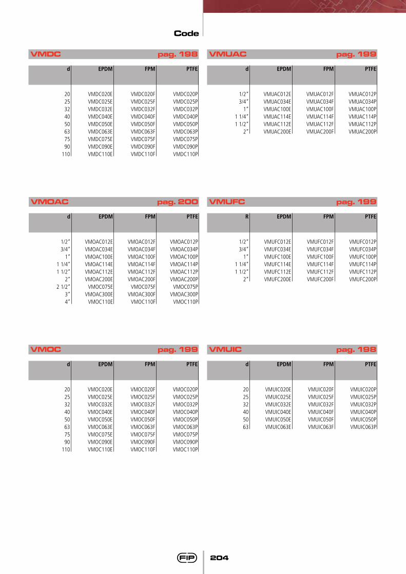
Code
VMUAC pag. 199
d
1/2”3/4”
1”1 1/4”1 1/2”
2”
EPDM
VMUAC012EVMUAC034EVMUAC100EVMUAC114EVMUAC112EVMUAC200E
FPM
VMUAC012FVMUAC034FVMUAC100FVMUAC114FVMUAC112FVMUAC200F
PTFE
VMUAC012PVMUAC034PVMUAC100PVMUAC114PVMUAC112PVMUAC200P
VMOC pag. 199
d
2025324050637590
110
EPDM
VMOC020EVMOC025EVMOC032EVMOC040EVMOC050EVMOC063EVMOC075EVMOC090EVMOC110E
FPM
VMOC020FVMOC025FVMOC032FVMOC040FVMOC050FVMOC063FVMOC075FVMOC090FVMOC110F
PTFE
VMOC020PVMOC025PVMOC032PVMOC040PVMOC050PVMOC063PVMOC075PVMOC090PVMOC110P
VMOAC pag. 200
d
1/2”3/4”
1”1 1/4”1 1/2”
2”2 1/2”
3”4”
EPDM
VMOAC012EVMOAC034EVMOAC100EVMOAC114EVMOAC112EVMOAC200E
VMOC075EVMOAC300E
VMOC110E
FPM
VMOAC012FVMOAC034FVMOAC100FVMOAC114FVMOAC112FVMOAC200F
VMOC075FVMOAC300F
VMOC110F
PTFE
VMOAC012PVMOAC034PVMOAC100PVMOAC114PVMOAC112PVMOAC200P
VMOC075PVMOAC300P
VMOC110P
VMDC pag. 198
d
2025324050637590
110
EPDM
VMDC020EVMDC025EVMDC032EVMDC040EVMDC050EVMDC063EVMDC075EVMDC090EVMDC110E
FPM
VMDC020FVMDC025FVMDC032FVMDC040FVMDC050FVMDC063FVMDC075FVMDC090FVMDC110F
PTFE
VMDC020PVMDC025PVMDC032PVMDC040PVMDC050PVMDC063PVMDC075PVMDC090PVMDC110P
VMUIC pag. 198
d
202532405063
EPDM
VMUIC020EVMUIC025EVMUIC032EVMUIC040EVMUIC050EVMUIC063E
FPM
VMUIC020FVMUIC025FVMUIC032FVMUIC040FVMUIC050FVMUIC063F
PTFE
VMUIC020PVMUIC025PVMUIC032PVMUIC040PVMUIC050PVMUIC063P
VMUFC pag. 199
R
1/2”3/4”
1”1 1/4”1 1/2”
2”
EPDM
VMUFC012EVMUFC034EVMUFC100EVMUFC114EVMUFC112EVMUFC200E
FPM
VMUFC012FVMUFC034FVMUFC100FVMUFC114FVMUFC112FVMUFC200F
PTFE
VMUFC012PVMUFC034PVMUFC100PVMUFC114PVMUFC112PVMUFC200P