
Viaggio all’interno di una macchina biorobotica - sssup.it · Corso di Orientamento residenziale...
39
20/02/2012 1 Viaggio all’interno di una macchina biorobotica 3 febbraio 2012 – San Miniato Cesare Stefanini Istituto di BioRobotica, Scuola Superiore Sant’Anna, Pisa Studiare ingegneria al Sant’Anna: Corso di Orientamento residenziale Automi ante litteram Tupilak Al Jazari Golem Nord Canada e Groenlandia Secondo le leggende Inuit, Tupilaq (o Tupilak) può essere creato da uno stregone e programmato per dare la caccia e uccidere un nemico Autore arabo, concepì dispositivi complessi, tra i quali quello della toilette con scarico d’acqua Leggenda ebraica, il golem è una statua di argilla, animata dalla magia cabalistica
Transcript of Viaggio all’interno di una macchina biorobotica - sssup.it · Corso di Orientamento residenziale...
20/02/2012
1
Viaggio all’interno di una
macchina biorobotica
3 febbraio 2012 – San Miniato
Cesare Stefanini
Istituto di BioRobotica, Scuola Superiore Sant’Anna, Pisa
Studiare ingegneria al Sant’Anna:
Corso di Orientamento residenziale
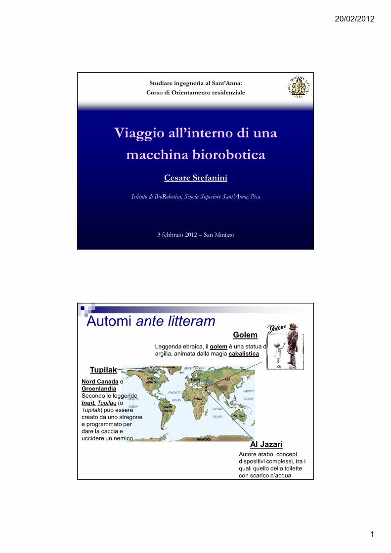
Automi ante litteram
Tupilak
Al Jazari
Golem
Nord Canada e GroenlandiaSecondo le leggende Inuit, Tupilaq (o Tupilak) può essere creato da uno stregone e programmato per dare la caccia e uccidere un nemico
Autore arabo, concepì dispositivi complessi, tra i quali quello della toilette con scarico d’acqua
Leggenda ebraica, il golem è una statua di argilla, animata dalla magia cabalistica
20/02/2012
2
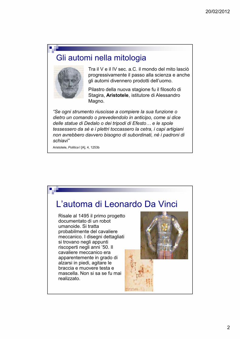
Tra il V e il IV sec. a.C. il mondo del mito lasciò progressivamente il passo alla scienza e anche gli automi divennero prodotti dell’uomo.
Pilastro della nuova stagione fu il filosofo di Stagira, Aristotele, istitutore di Alessandro Magno.
“Se ogni strumento riuscisse a compiere la sua funzione o
dietro un comando o prevedendolo in anticipo, come si dice
delle statue di Dedalo o dei tripodi di Efesto… e le spole
tessessero da sé e i plettri toccassero la cetra, i capi artigiani
non avrebbero davvero bisogno di subordinati, né i padroni di
schiavi”
Aristotele, Politica I [A], 4, 1253b
Gli automi nella mitologia
L’automa di Leonardo Da VinciRisale al 1495 il primo progetto documentato di un robot umanoide. Si tratta probabilmente del cavaliere meccanico. I disegni dettagliati si trovano negli appunti riscoperti negli anni ’50. Il cavaliere meccanico era apparentemente in grado di alzarsi in piedi, agitare le braccia e muovere testa e mascella. Non si sa se fu mai realizzato.
20/02/2012
3
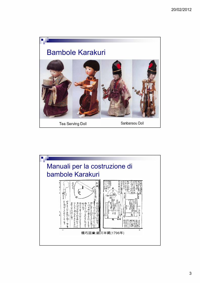
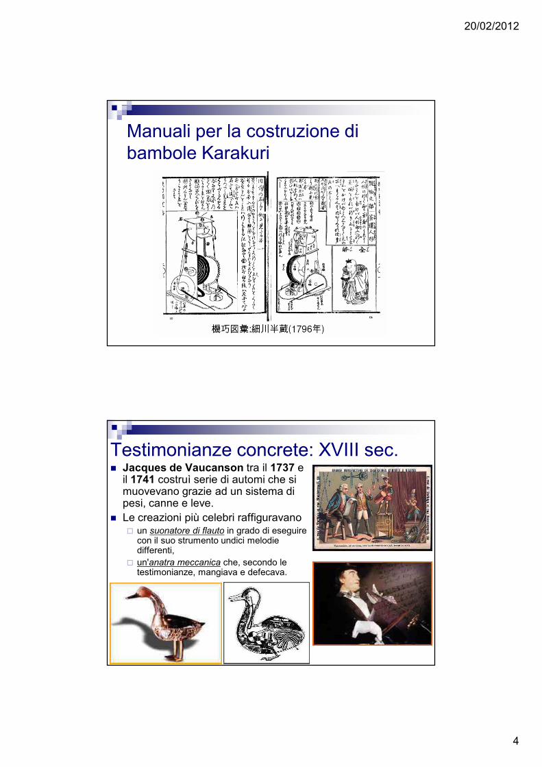
Bambole Karakuri
I manuali di Karakuri
Manuali per la costruzione di bambole Karakuri
20/02/2012
4
Manuali per la costruzione di bambole Karakuri
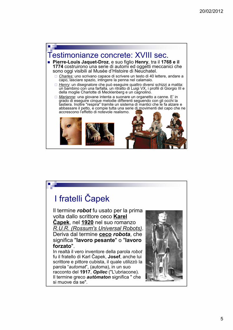
Testimonianze concrete: XVIII sec.� Jacques de Vaucanson tra il 1737 e
il 1741 costruì serie di automi che si muovevano grazie ad un sistema di pesi, canne e leve.
� Le creazioni più celebri raffiguravano � un suonatore di flauto in grado di eseguire
con il suo strumento undici melodie differenti,
� un'anatra meccanica che, secondo le testimonianze, mangiava e defecava.
20/02/2012
5
Testimonianze concrete: XVIII sec.� Pierre-Louis Jaquet-Droz, e suo figlio Henry, tra il 1768 e il
1774 costruirono una serie di automi ed oggetti meccanici che sono oggi visibili al Musée d’Histoire di Neuchatel. � Charles: uno scrivano capace di scrivere un testo di 40 lettere, andare a
capo, lasciare spazio, intingere la penna nel calamaio. � Henry: un disegnatore che può eseguire quattro diversi schizzi a matita:
un bambino con una farfalla, un ritratto di Luigi VX, i profili di Giorgio III e della moglie Charlotte di Mecklenberg e un cagnolino.
� Marianne: una giovane intenta a suonare un organetto a canne. E’ in grado di eseguire cinque melodie differenti seguendo con gli occhi la tastiera. Inoltre "respira" tramite un sistema di mantici che le fa alzare e abbassare il petto, e compie tutta una serie di movimenti del capo che ne accrescono l’effetto di notevole realismo.
I fratelli ČapekIl termine robot fu usato per la prima volta dallo scrittore ceco Karel Čapek, nel 1920 nel suo romanzo R.U.R. (Rossum's Universal Robots). Deriva dal termine ceco robota, che significa "lavoro pesante" o "lavoro forzato".In realtà il vero inventore della parola robotfu il fratello di Karl Čapek, Josef, anche lui scrittore e pittore cubista, il quale utilizzò la parola “automat”, (automa), in un suo racconto del 1917, Opilec ("L'ubriacone). Il termine greco autòmaton significa " che si muove da se".
20/02/2012
6
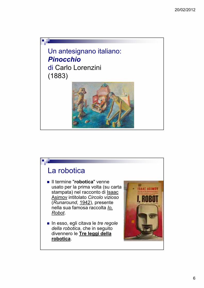
Un antesignano italiano: Pinocchio
di Carlo Lorenzini (1883)
La robotica� Il termine "robotica" venne
usato per la prima volta (su carta stampata) nel racconto di Isaac Asimov intitolato Circolo vizioso(Runaround, 1942), presente nella sua famosa raccolta Io, Robot.
� In esso, egli citava le tre regole della robotica, che in seguito divennero le Tre leggi della robotica.
20/02/2012
7
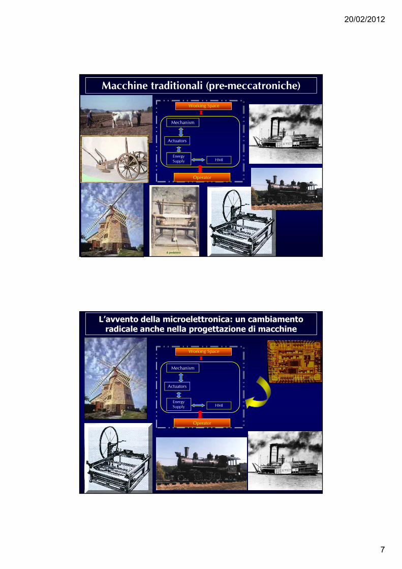
Macchine traditionali (pre-meccatroniche)
Mechanism
Working Space
HMI
Actuators
Energy
Supply
Operator
L’avvento della microelettronica: un cambiamento radicale anche nella progettazione di macchine
Mechanism
Working Space
HMI
Actuators
Energy
Supply
Operator
20/02/2012
8
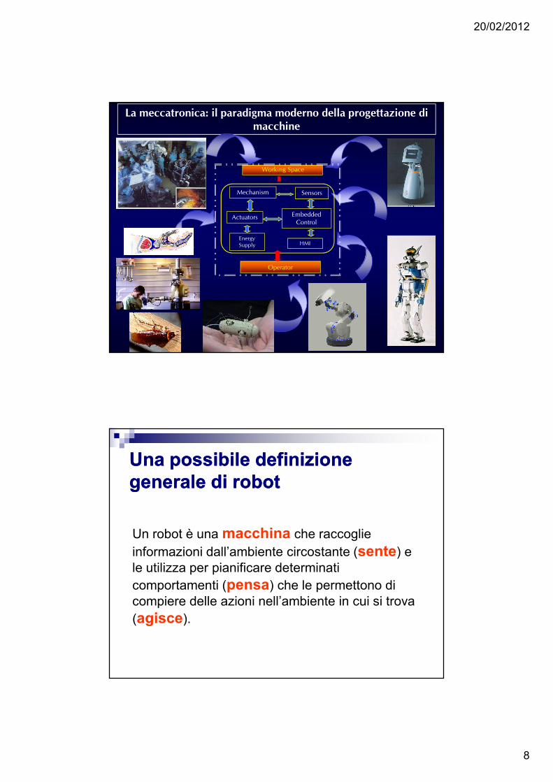
La meccatronica: il paradigma moderno della progettazione di
macchine
Mechanism
Working Space
HMI
Actuators Embedded
Control
Sensors
Energy
Supply
Operator
Una possibile definizione Una possibile definizione generale di robotgenerale di robot
Un robot è una macchina che raccoglie informazioni dall’ambiente circostante (sente) e le utilizza per pianificare determinati comportamenti (pensa) che le permettono di compiere delle azioni nell’ambiente in cui si trova (agisce).
20/02/2012
9
Sente, pensa e agisce… Sente, pensa e agisce… Ma comeMa come??
Cosa serve per fare un Cosa serve per fare un robot?robot?
20/02/2012
10
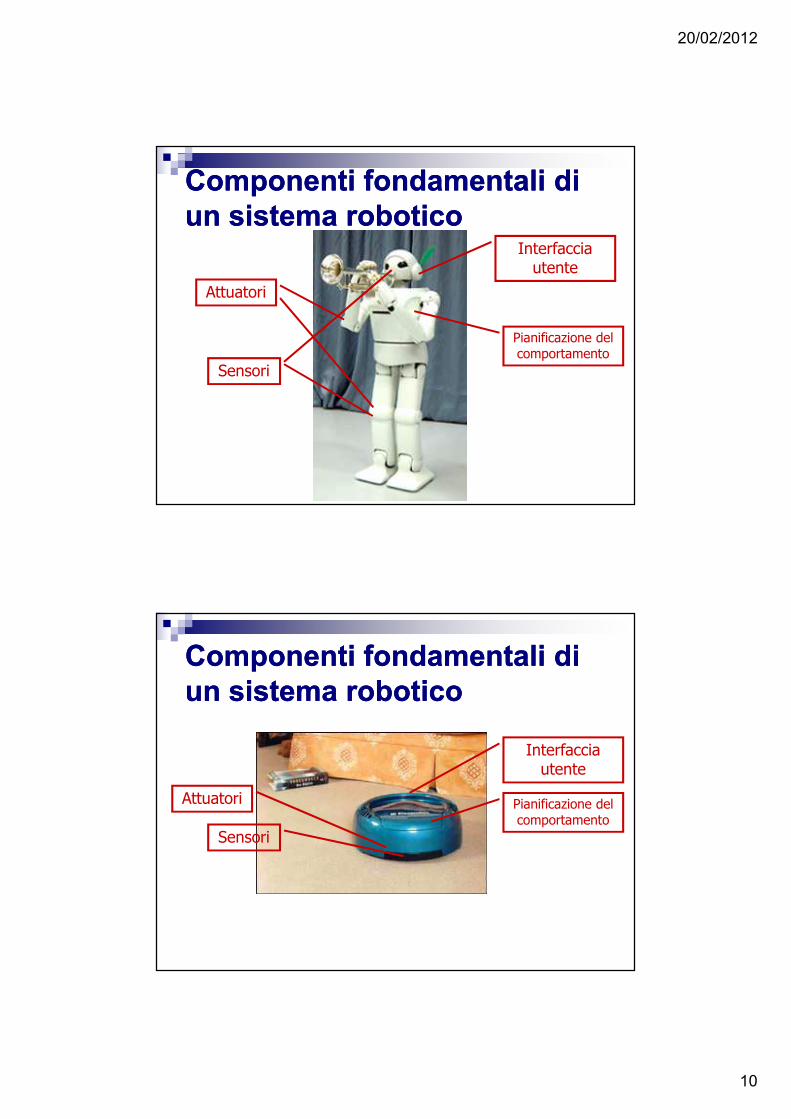
Componenti fondamentali di Componenti fondamentali di un sistema roboticoun sistema robotico
Sensori
Attuatori
Pianificazione del comportamento
Interfaccia utente
Componenti fondamentali di Componenti fondamentali di un sistema roboticoun sistema robotico
Sensori
Attuatori Pianificazione del comportamento
Interfaccia utente
20/02/2012
11
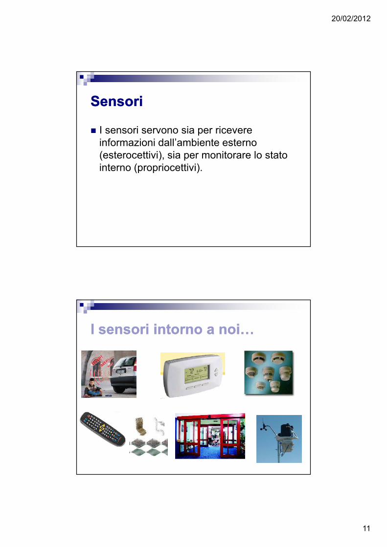
SensoriSensori
� I sensori servono sia per ricevere informazioni dall’ambiente esterno (esterocettivi), sia per monitorare lo stato interno (propriocettivi).
I sensori intorno a noi…I sensori intorno a noi…
20/02/2012
12
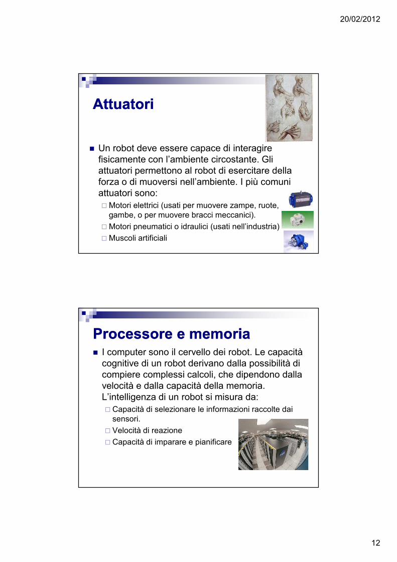
AttuatoriAttuatori
� Un robot deve essere capace di interagire fisicamente con l’ambiente circostante. Gli attuatori permettono al robot di esercitare della forza o di muoversi nell’ambiente. I più comuni attuatori sono:� Motori elettrici (usati per muovere zampe, ruote,
gambe, o per muovere bracci meccanici).
� Motori pneumatici o idraulici (usati nell’industria)
� Muscoli artificiali
Processore e memoriaProcessore e memoria� I computer sono il cervello dei robot. Le capacità
cognitive di un robot derivano dalla possibilità di compiere complessi calcoli, che dipendono dalla velocità e dalla capacità della memoria. L’intelligenza di un robot si misura da:� Capacità di selezionare le informazioni raccolte dai
sensori.
� Velocità di reazione
� Capacità di imparare e pianificare
20/02/2012
13
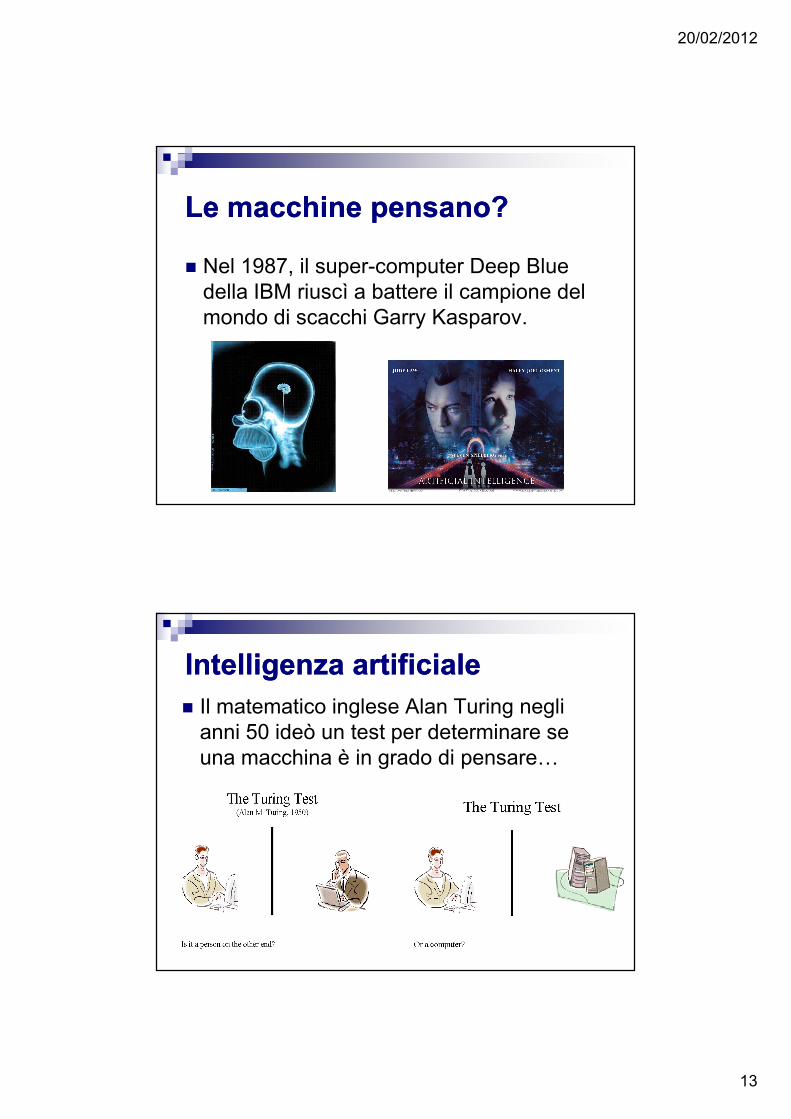
Le macchine pensano?Le macchine pensano?
� Nel 1987, il super-computer Deep Blue della IBM riuscì a battere il campione del mondo di scacchi Garry Kasparov.
Intelligenza artificialeIntelligenza artificiale� Il matematico inglese Alan Turing negli
anni 50 ideò un test per determinare se una macchina è in grado di pensare…
20/02/2012
14
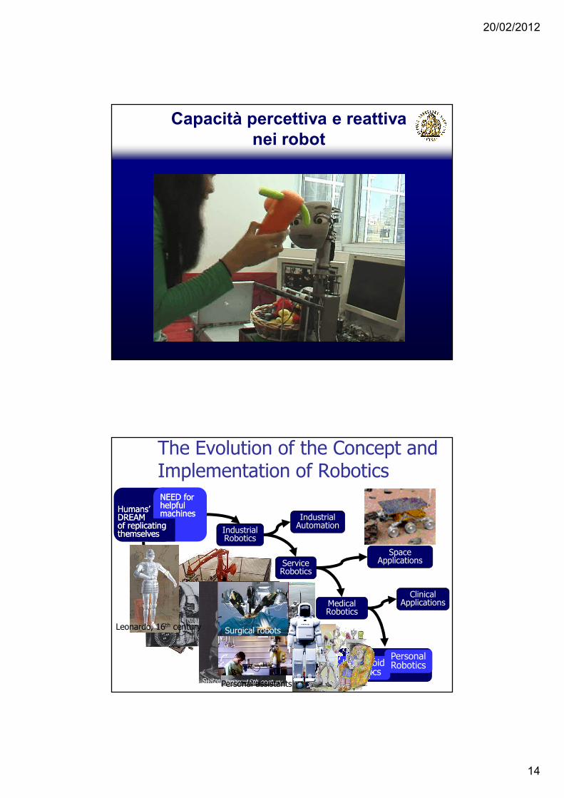
Capacità percettiva e reattiva nei robot
NEED for NEED for helpful helpful machinesmachines
Humans’ Humans’ DREAMDREAMof replicating of replicating themselvesthemselves
The Evolution of the Concept and Implementation of Robotics
Industrial Robotics
Service Robotics
Industrial Automation
SpaceApplications
MedicalRobotics
Personal RoboticsHumanoid
Robotics
Clinical Applications
Switzerland, 17th centuryJapan, 18th century
Leonardo, 16th century
Personal assistants
Surgical robots
20/02/2012
15
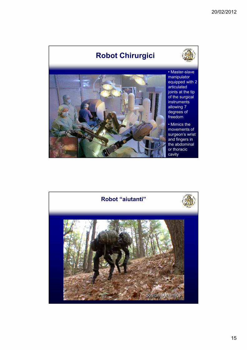
• Master-slave manipulator equipped with 2 articulated joints at the tip of the surgical instruments allowing 7 degrees of freedom
• Mimics the movements of surgeon’s wrist and fingers in the abdominal or thoracic cavity
Robot Chirurgici
Robot “aiutanti”

20/02/2012
16
Robot bipedi
LAMPETRA
“Life-like Artefacts for Motor-Postural Experiments and
Development of new Control Technologies inspired by Rapid
Animal locomotion”
EU FET Bio-ICT Convergence Project n. 216100
Final Review Meeting – September 20, 2011
European Commission - 25, Avenue de Beaulieu, BruxellesRoom BU 25 0/S2

20/02/2012
17
The Lampetra Consortium
Bioengineering/bio-robotics• Scuola Superiore Sant'Anna, Italy (prof. Paolo
Dario) Project Coordinator• Ecole Polytechnique Fédérale de Lausanne (prof.
Auke Ijspeert)
Neuroscience• Karolinska Institutet, Sweden (prof. Sten Grillner)• Centre de Recherche INSERM U862, France (prof.
Jean Marie Cabelguen)
Biology-focused Computer Science• Royal Institute of Technology, Sweden (prof. Örjan
Ekeberg)
Starting date: 01/02/2008
Duration: 36+6 months
Funding: 1.7 M€
Five partners, Four countries, Three scientific areas
Participants
Paolo Dario, Cesare Stefanini, Stefano Orofino, Lorenza Capantini, Stefano Mintchev, Stefano Marrazza
Peter Wallén
Örjan Ekeberg
Auke Ijspeert, Konstantinos Karakasiliotis, Jeremie Knuesel
Jean-Marie Cabelguen, Vanessa Charrier, Alexia Mathou
Project Officer: José-Luis Fernández-Villacañas Martín
Reviewers: Mattia Frasca, Tom Ziemke
20/02/2012
18
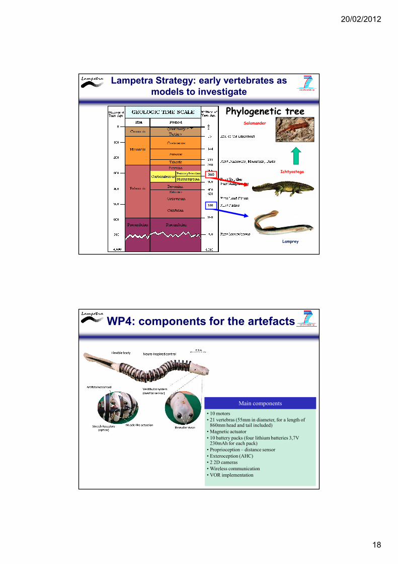
Phylogenetic tree
Lamprey
530
360Ichtyostega
Salamander
INTRODUCTION
Lampetra Strategy: early vertebrates as models to investigate
WP4: components for the artefacts
• 10 motors
• 21 vertebras (55mm in diameter, for a length of 860mm head and tail included)
• Magnetic actuator
• 10 battery packs (four lithium batteries 3,7V 230mAh for each pack)
• Proprioception – distance sensor
• Exteroception (AHC)
• 2 2D cameras
• Wireless communication
• VOR implementation
Main components
20/02/2012
19
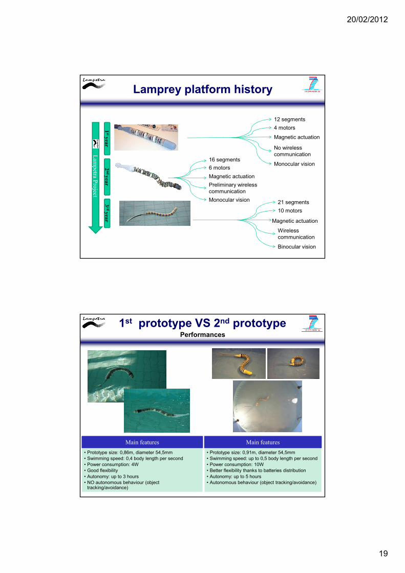
Lamprey platform history
1styear
2nd year
3rdyear
Lam
petra P
roject
12 segments
Magnetic actuation
Monocular vision
4 motors
No wireless communication
6 motors
Magnetic actuation
Monocular vision
16 segments
Preliminary wireless communication
21 segments
Binocular vision
10 motors
Wireless communication
Magnetic actuation
1st prototype VS 2nd prototype
• Prototype size: 0,86m, diameter 54,5mm• Swimming speed: 0,4 body length per second• Power consumption: 4W• Good flexibility • Autonomy: up to 3 hours• NO autonomous behaviour (object
tracking/avoidance)
• Prototype size: 0,91m, diameter 54,5mm• Swimming speed: up to 0,5 body length per second• Power consumption: 10W• Better flexibility thanks to batteries distribution• Autonomy: up to 5 hours• Autonomous behaviour (object tracking/avoidance)
Performances
Main features Main features
20/02/2012
20
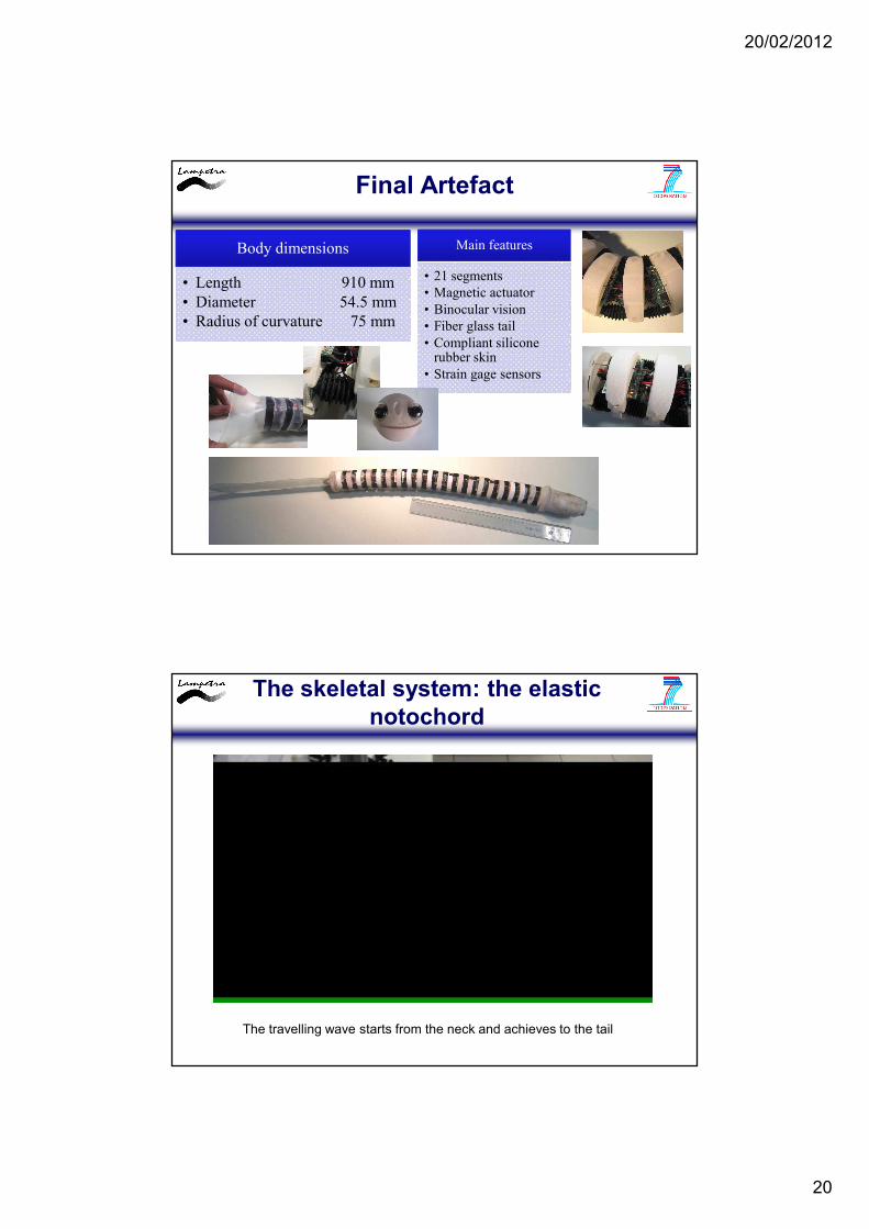
Final Artefact
Body dimensions
• Length 910 mm
• Diameter 54.5 mm
• Radius of curvature 75 mm
Main features
• 21 segments
• Magnetic actuator
• Binocular vision
• Fiber glass tail
• Compliant silicone rubber skin
• Strain gage sensors
The skeletal system: the elastic notochord
The travelling wave starts from the neck and achieves to the tail
20/02/2012
21
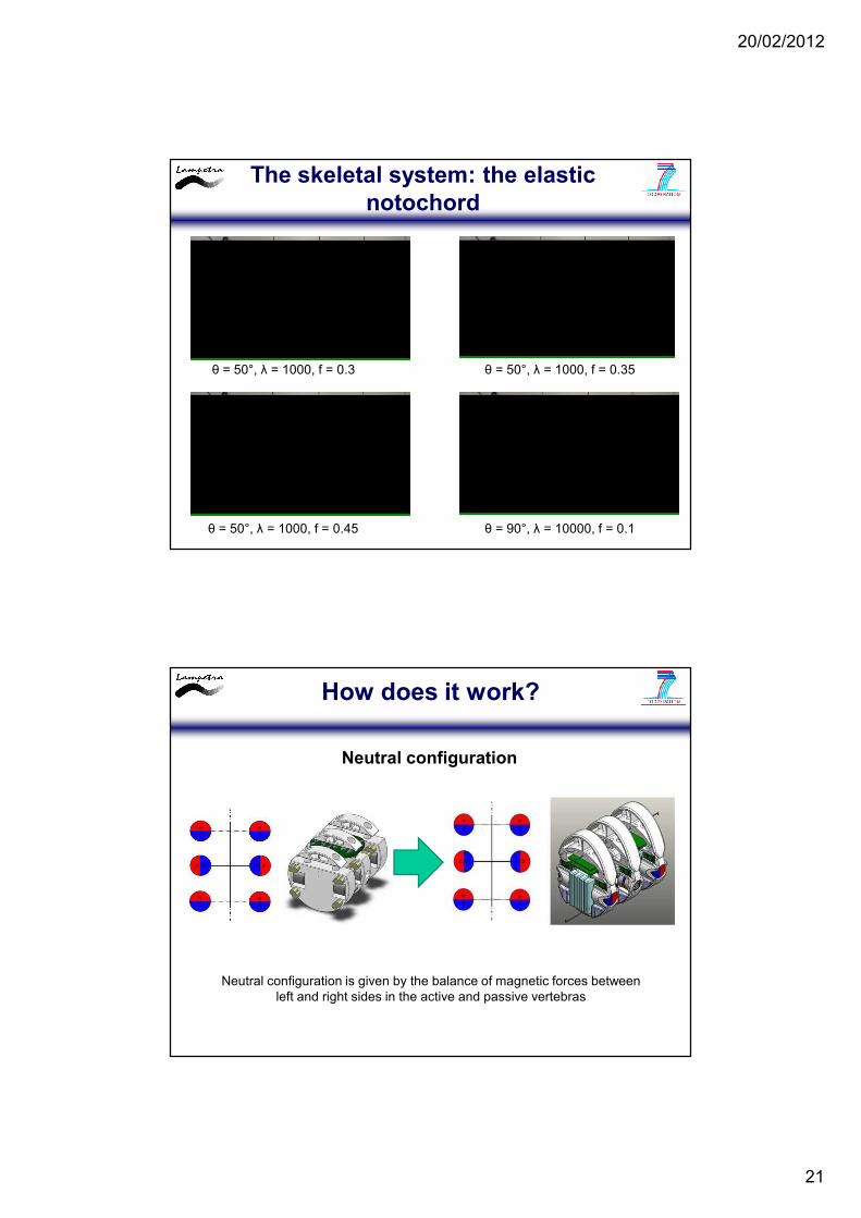
The skeletal system: the elastic notochord
θ = 50°, λ = 1000, f = 0.3 θ = 50°, λ = 1000, f = 0.35
θ = 50°, λ = 1000, f = 0.45 θ = 90°, λ = 10000, f = 0.1
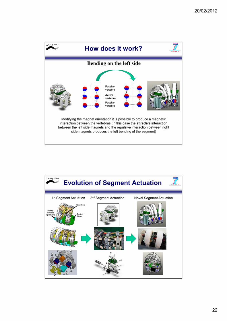
How does it work?
Neutral configuration
Neutral configuration is given by the balance of magnetic forces between left and right sides in the active and passive vertebras
20/02/2012
22
How does it work?
Bending on the left side
Passive vertebra
Active vertebra
Passive vertebra
Modifying the magnet orientation it is possible to produce a magnetic interaction between the vertebras (in this case the attractive interaction
between the left side magnets and the repulsive interaction between right side magnets produces the left bending of the segment)
Evolution of Segment Actuation
Notochord
Control Board
Battery (wireless operation)
1
2
3
4
5
6
7
81
1st Segment Actuation 2nd Segment Actuation Novel Segment Actuation

20/02/2012
23
Novel Segment Actuation
1. Screw
2. Volume increase
3. Upper part
4. Artificial notochord (harmonic steel wires, ø = 0,7mm)
5. Stretch sensors board
6. Roller bearing
7. Bearing magnet (Ergal 7075)
8. Permanent magnets (Neodymium N48, cylindrical shape, radial magnetization)
9. Bearing magnet with transmission shaft (Ergal 7075)
10. DC motor (with encoder, nominal power of 0,26W)
11. Gear system (two gear, Delrin, 15 cog)
12. Mechanical bumpers (silicone rubber)
13. Main structure (acrylic resin)
2
8
3
4
5
1
5
11
6
6
7
7
8
9
10
13
12
Novel Segment Actuation
4
1
5
6
7
3
2
Polymeric structure
Battery boards
Permanent magnets
Shock absorber
Stretch sensors
CPGs boards
Artificial notochord
20/02/2012
24
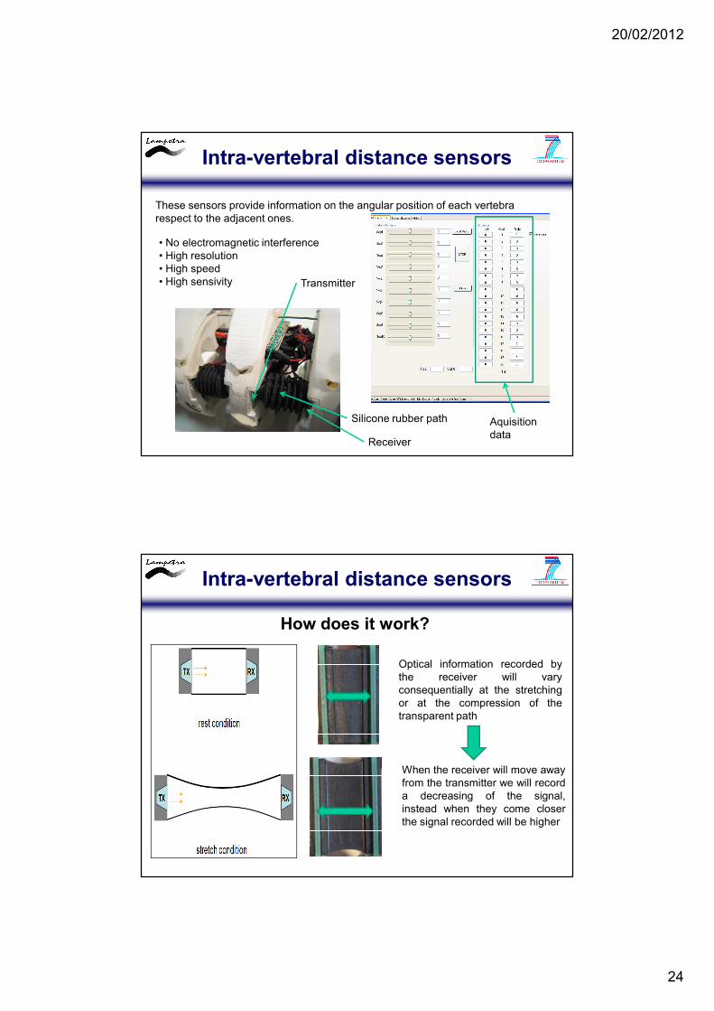
Intra-vertebral distance sensors
These sensors provide information on the angular position of each vertebra respect to the adjacent ones.
• No electromagnetic interference• High resolution• High speed• High sensivity Transmitter
Silicone rubber path
Receiver
Aquisition data
Intra-vertebral distance sensors
How does it work?
Optical information recorded bythe receiver will varyconsequentially at the stretchingor at the compression of thetransparent path
When the receiver will move awayfrom the transmitter we will recorda decreasing of the signal,instead when they come closerthe signal recorded will be higher
20/02/2012
25
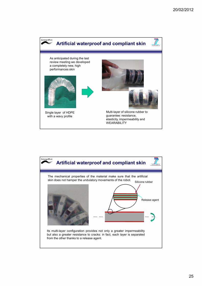
Artificial waterproof and compliant skin
Single layer of HDPE with a wavy profile
Multi-layer of silicone rubber to guarantee: resistance, elasticity, impermeability and WEARABILITY
As anticipated during the last review meeting we developed a completely new, high performances skin
Artificial waterproof and compliant skin
The mechanical properties of the material make sure that the artificialskin does not hamper the undulatory movements of the robot.
Its multi-layer configuration provides not only a greater impermeabilitybut also a greater resistance to cracks: in fact, each layer is separatedfrom the other thanks to a release agent.
Silicone rubber
Release agent
20/02/2012
26
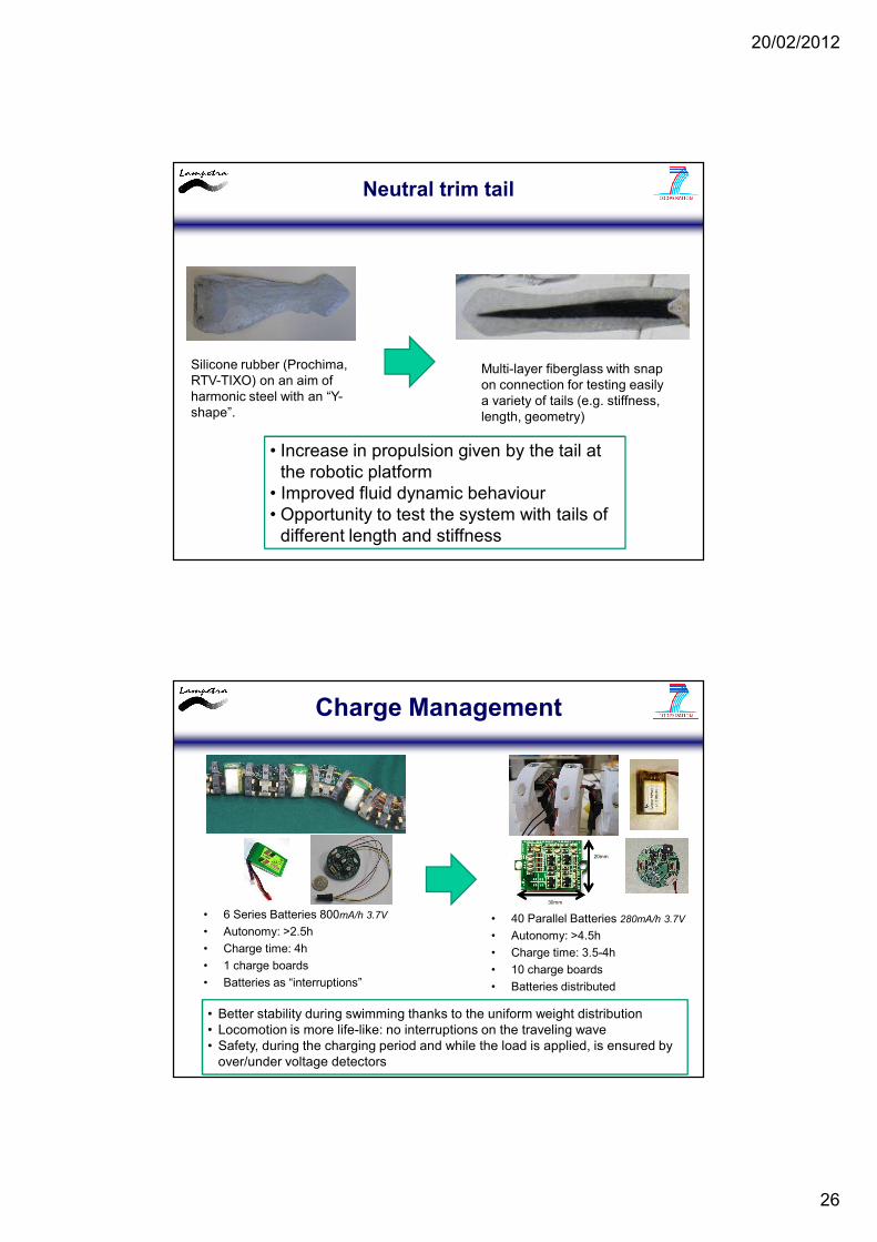
Neutral trim tail
Silicone rubber (Prochima, RTV-TIXO) on an aim of harmonic steel with an “Y-shape”.
Multi-layer fiberglass with snap on connection for testing easily a variety of tails (e.g. stiffness, length, geometry)
• Increase in propulsion given by the tail at the robotic platform
• Improved fluid dynamic behaviour• Opportunity to test the system with tails of
different length and stiffness
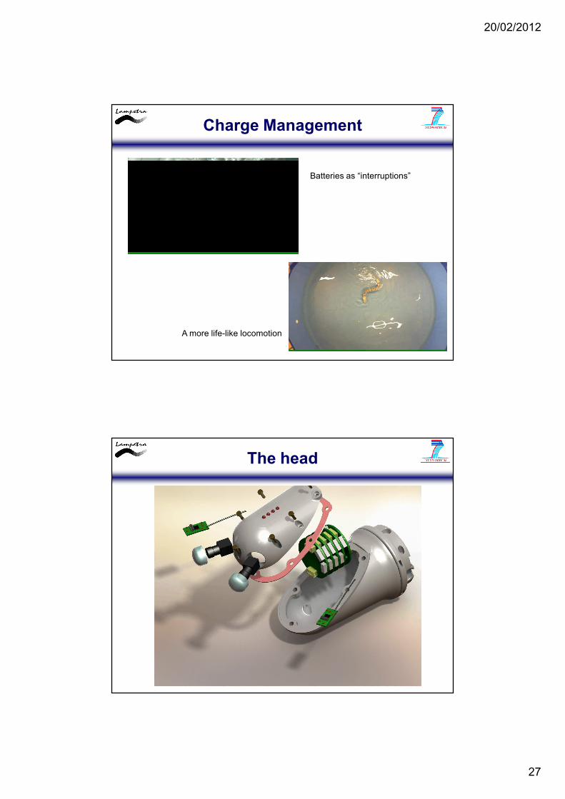
Charge Management
• 40 Parallel Batteries 280mA/h 3.7V
• Autonomy: >4.5h
• Charge time: 3.5-4h
• 10 charge boards
• Batteries distributed
30mm
20mm
• 6 Series Batteries 800mA/h 3.7V
• Autonomy: >2.5h
• Charge time: 4h
• 1 charge boards
• Batteries as “interruptions”
• Better stability during swimming thanks to the uniform weight distribution• Locomotion is more life-like: no interruptions on the traveling wave• Safety, during the charging period and while the load is applied, is ensured by
over/under voltage detectors
20/02/2012
27
Charge Management
Batteries as “interruptions”
A more life-like locomotion
The head
20/02/2012
28
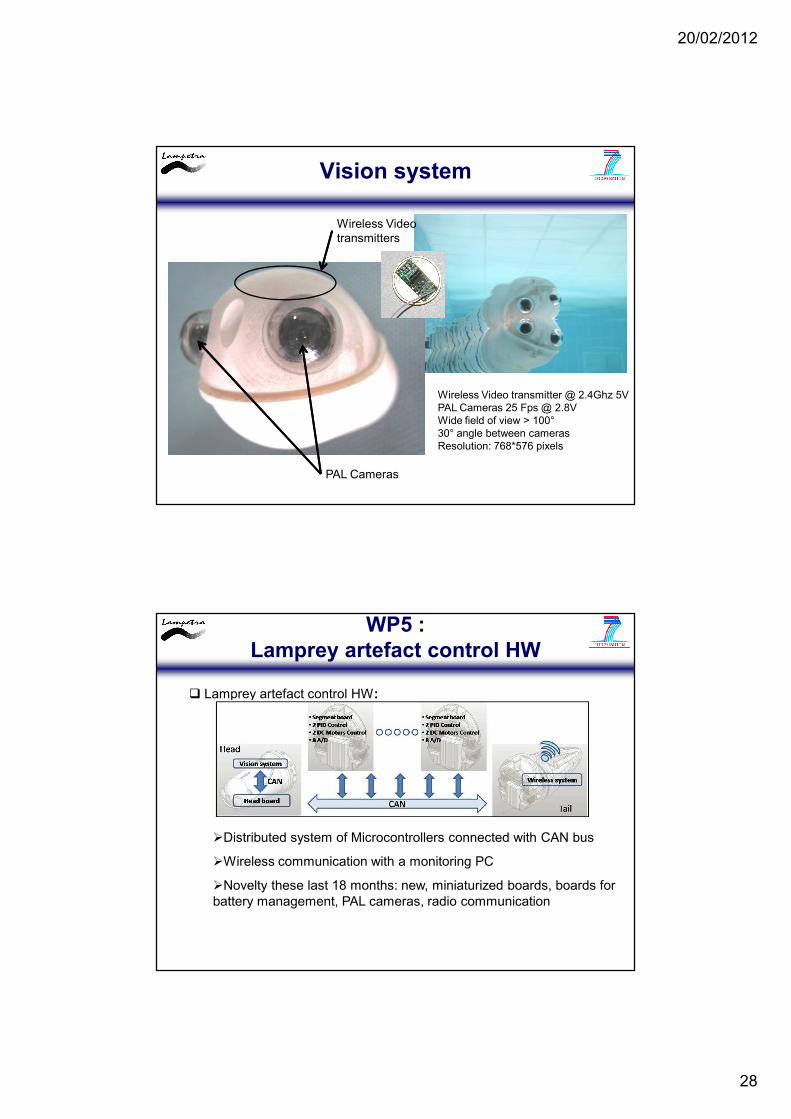
Vision system
Wireless Video transmitters
PAL Cameras
Wireless Video transmitter @ 2.4Ghz 5VPAL Cameras 25 Fps @ 2.8VWide field of view > 100°30° angle between camerasResolution: 768*576 pixels
WP5 : Lamprey artefact control HW
� Lamprey artefact control HW:
�Distributed system of Microcontrollers connected with CAN bus
�Wireless communication with a monitoring PC
�Novelty these last 18 months: new, miniaturized boards, boards for battery management, PAL cameras, radio communication
20/02/2012
29
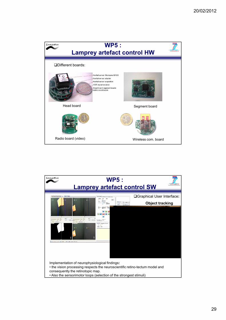
WP5 : Lamprey artefact control HW
�Different boards:
Head board Segment board
Wireless com. boardRadio board (video)
WP5 : Lamprey artefact control SW
�Graphical User Interface:
Object tracking
Implementation of neurophysiological findings:• the vision processing respects the neuroscientific retino-tectum model and consequently the retinotopic map.• Also the sensorimotor loops (selection of the strongest stimuli)
20/02/2012
30
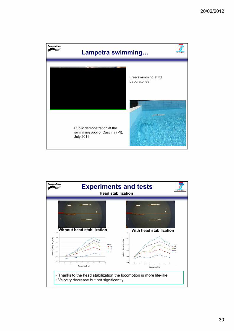
Lampetra swimming…
Free swimming at KI Laboratories
Public demonstration at the swimming pool of Cascina (PI),July 2011
Experiments and testsHead stabilization
Without head stabilization With head stabilization
frequency [Hz]
velo
city
[body
length
/s]
frequency [Hz]
velo
city
[body
length
/s]
• Thanks to the head stabilization the locomotion is more life-like• Velocity decrease but not significantly
20/02/2012
31
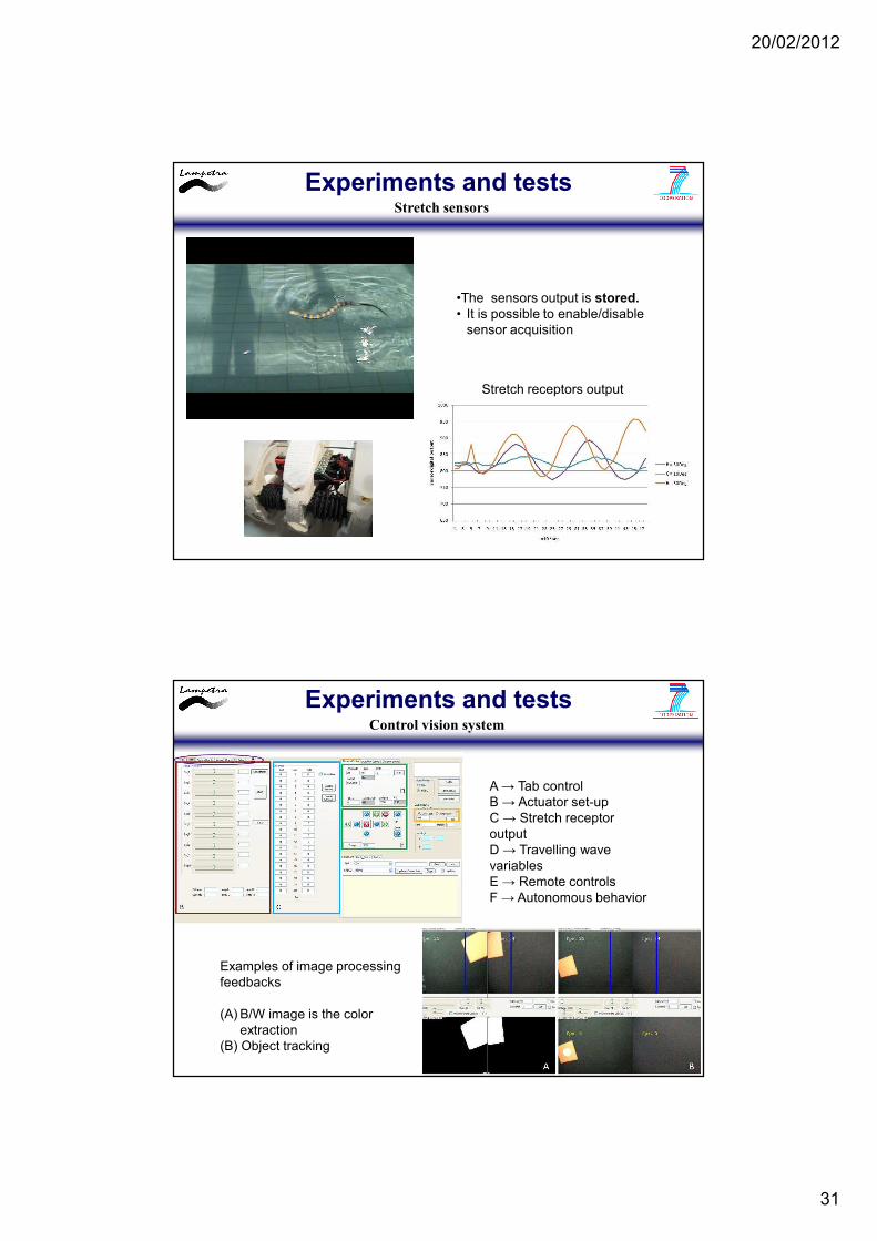
Stretch receptors output
•The sensors output is stored.• It is possible to enable/disable
sensor acquisition
Experiments and testsStretch sensors
A → Tab controlB → Actuator set-upC → Stretch receptor outputD → Travelling wave variablesE → Remote controlsF → Autonomous behavior
Examples of image processingfeedbacks
(A) B/W image is the color extraction
(B) Object tracking
Experiments and testsControl vision system
20/02/2012
32
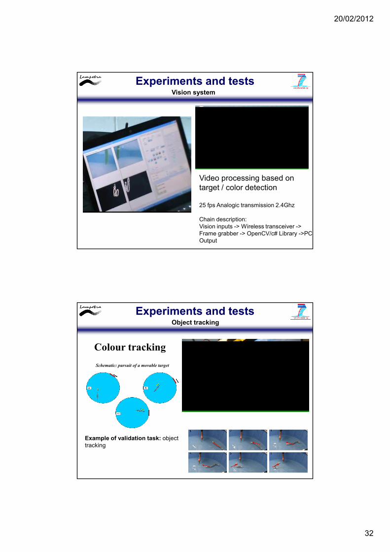
Video processing based on target / color detection
25 fps Analogic transmission 2.4Ghz
Chain description:Vision inputs -> Wireless transceiver -> Frame grabber -> OpenCV/c# Library ->PC Output
Experiments and testsVision system
Example of validation task: object tracking
Schematic: pursuit of a movable target
Colour tracking
Experiments and testsObject tracking
20/02/2012
33
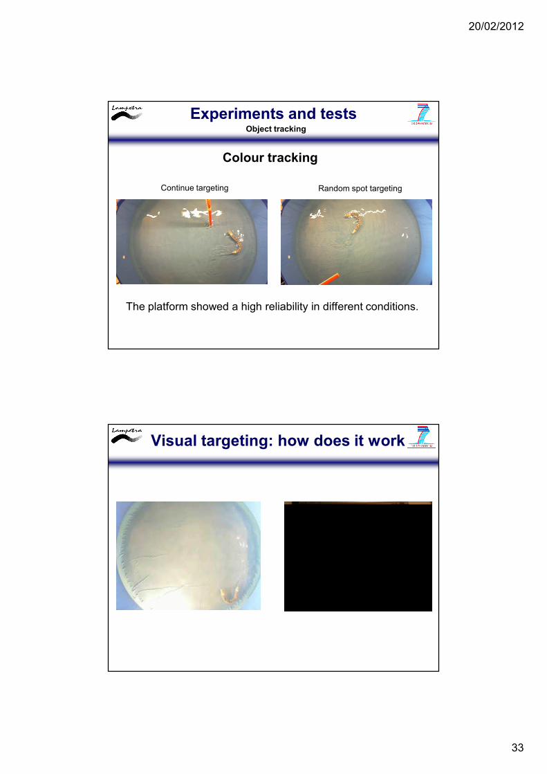
Continue targeting Random spot targeting
The platform showed a high reliability in different conditions.
Experiments and testsObject tracking
Colour tracking
Visual targeting: how does it work
20/02/2012
34
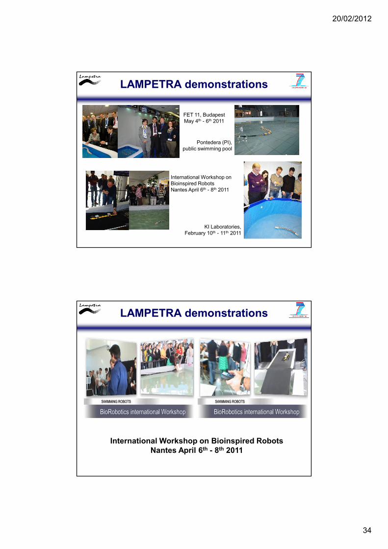
LAMPETRA demonstrations
FET 11, BudapestMay 4th - 6th 2011
International Workshop on Bioinspired RobotsNantes April 6th - 8th 2011
Pontedera (PI), public swimming pool
KI Laboratories,February 10th - 11th 2011
LAMPETRA demonstrations
International Workshop on Bioinspired RobotsNantes April 6th - 8th 2011
20/02/2012
35
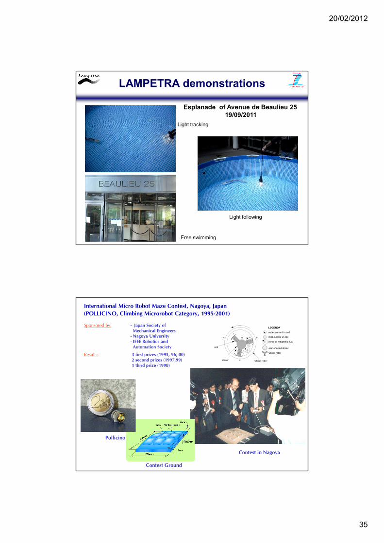
LAMPETRA demonstrations
Esplanade of Avenue de Beaulieu 2519/09/2011
Light following
Light tracking
Free swimming
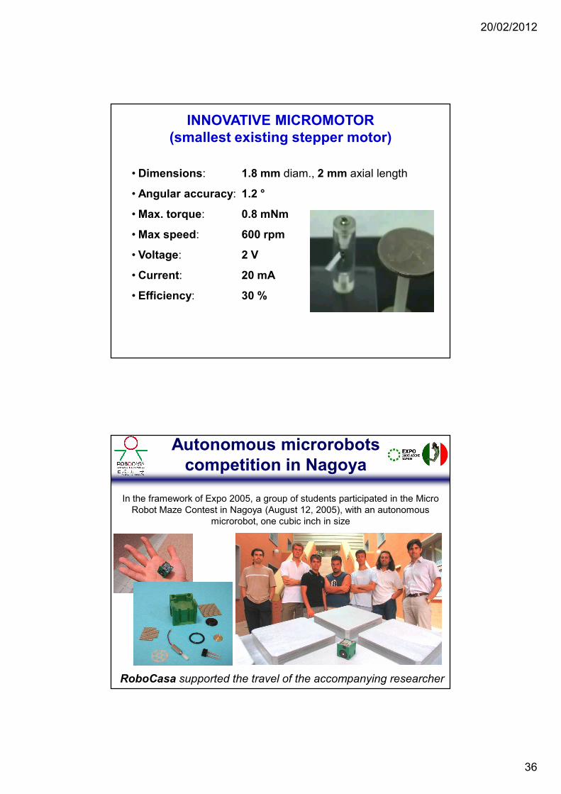
Contest Ground
International Micro Robot Maze Contest, Nagoya, Japan
(POLLICINO, Climbing Microrobot Category, 1995-2001)
Sponsored by: - Japan Society of
Mechanical Engineers
- Nagoya University
- IEEE Robotics and
Automation Society
Results: 3 first prizes (1995, 96, 00)
2 second prizes (1997,99)
1 third prize (1998)
Pollicino
A'
B'C'
C
O
wheel rotorstator
coil
LEGENDA
outlet current in coil
inlet current in coil
verse of magnetic flux
star shaped stator
wheel rotorA
B
Contest in Nagoya
20/02/2012
36
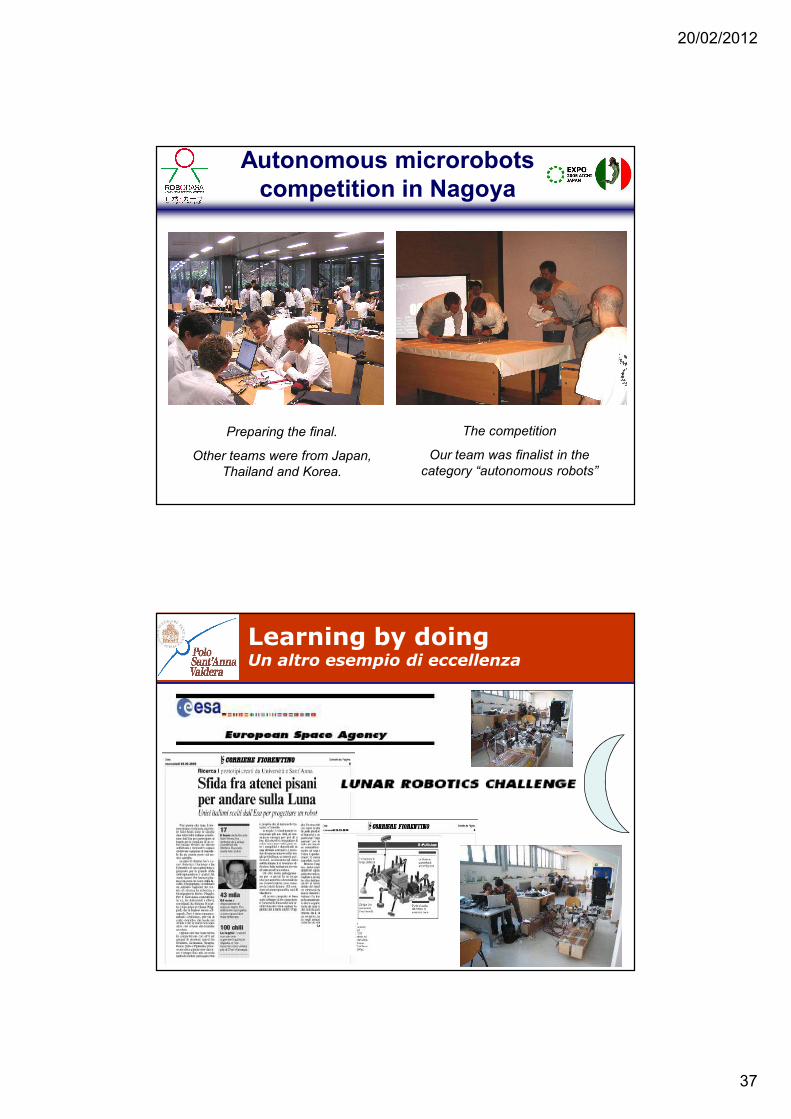
INNOVATIVE MICROMOTOR (smallest existing stepper motor)
• Dimensions: 1.8 mm diam., 2 mm axial length
• Angular accuracy: 1.2 °
• Max. torque: 0.8 mNm
• Max speed: 600 rpm
• Voltage: 2 V
• Current: 20 mA
• Efficiency: 30 %
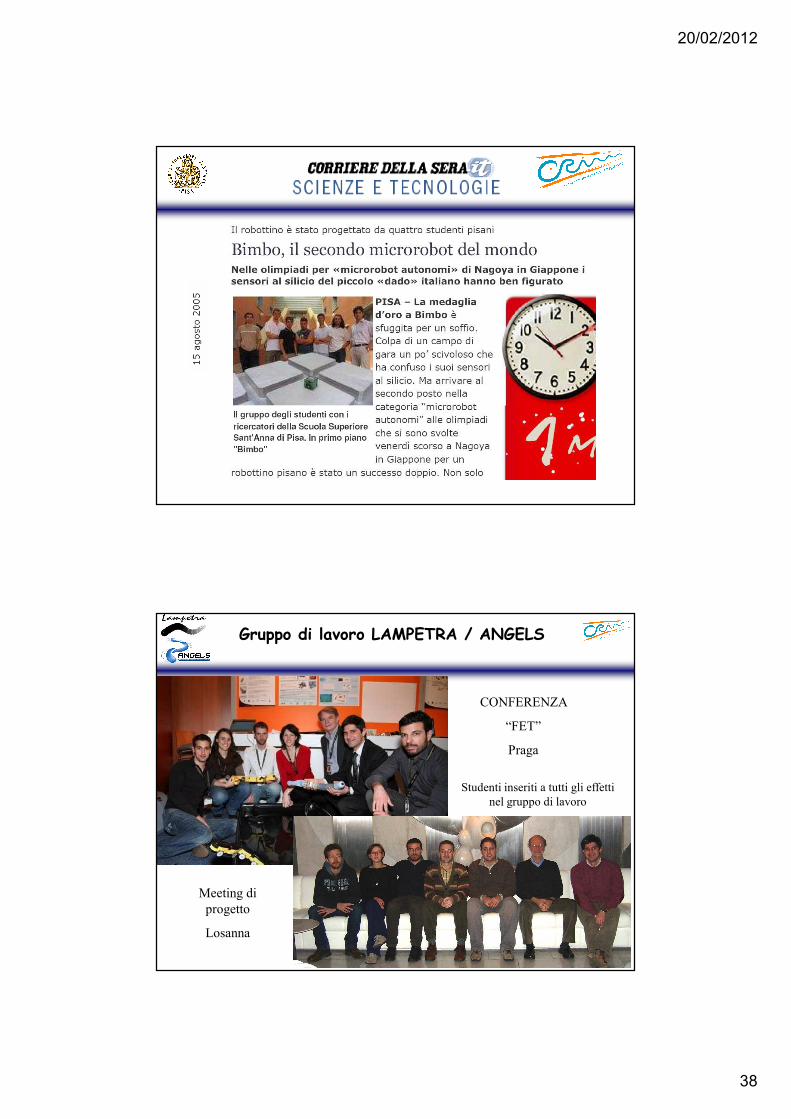
Autonomous microrobots competition in Nagoya
RoboCasa supported the travel of the accompanying researcher
In the framework of Expo 2005, a group of students participated in the Micro Robot Maze Contest in Nagoya (August 12, 2005), with an autonomous
microrobot, one cubic inch in size
20/02/2012
37
The competition
Our team was finalist in the
category “autonomous robots”
Autonomous microrobots competition in Nagoya
Preparing the final.
Other teams were from Japan,
Thailand and Korea.
Learning by doingUn altro esempio di eccellenza
20/02/2012
38
Gruppo di lavoro LAMPETRA / ANGELS
CONFERENZA
“FET”
Praga
Meeting di
progetto
Losanna
Studenti inseriti a tutti gli effetti
nel gruppo di lavoro


![SOMMARIO: 1. Premessa – 2. Breve evoluzione dello Stato ... · Le prime forme di «interventismo statale ante litteram» (L. VENTURA, 2010 [5], 112) ... primi istituti di protezione](https://static.fdocumenti.com/doc/165x107/5c65ed2f09d3f2e4308b7464/sommario-1-premessa-2-breve-evoluzione-dello-stato-le-prime-forme.jpg)