VE801 VE801T VE801R please visit our website...
2
4 1 2 1 2 3 4 1 2 3 1 2 3 VE801 HDMI HDBaseT-Lite Extender Quick Start Guide VE801 Alargador HDMI HDBaseT-Lite Guía rápida Système d'extension HDBaseT-Lite HDMI VE801 – Guide de démarrage rapide Estensore HDMI HDBaseT-Lite VE801 - Guida rapida VE801 HDBaseT-Lite HDMI-Verlängerung Kurzanleitung Краткое руководство пользователя удлинителя HDMI HDBaseT-Lite VE801 www.aten.com www.aten.com www.aten.com www.aten.com www.aten.com www.aten.com Package Contents Hardware Review A VE801T Front and Rear View 1. F/W Upgrade Port 2. HDMI Input Port 3. Power Jack 4. HDBaseT Output Port VE801T Top View 1. Link LED 2. Power LED VE801R Front and Rear View 1. Power Jack 2. HDBaseT Input Port 3. F/W Upgrade Port 4. HDMI Output Port VE801R Top View 1. HDMI Out LED Presentación del hardware A VE801T – Vistas frontal y posterior 1. Puerto de actualización del firmware 2. Puerto de entrada HDMI 3. Entrada de alimentación 4. Puerto de salida HDBaseT VE801T – Panel superior 1. Indicador de enlace (Link) 2. Indicador de alimentación VE801R – Vistas frontal y posterior 1. Entrada de alimentación 2. Puerto de entrada HDBaseT 3. Puerto de actualización del firmware 4. Puerto de salida HDMI VE801R – Panel superior 1. Indicador LED de salida HDMI Description de l’appareil A Vue avant et arrière VE801T 1. Port de mise à niveau du microprogramme 2. Port d’entrée HDMI 3. Prise d’alimentation 4. Port de sortie HDBaseT Vue supérieure du VE801T 1. Voyant de liaison (Link) 2. Voyant d’alimentation Vue avant et arrière VE801R 1. Prise d’alimentation 2. Port d’entrée HDBaseT 3. Port de mise à niveau du microprogramme 4. Port de sortie HDMI Vue supérieure du VE801R 1. Voyant de sortie HDMI Hardware A VE801T – vista anteriore e posteriore 1. Porta per aggiornamento F/W 2. Porta d’ingresso HDMI 3. Presa d’alimentazione 4. Porta d’uscita HDBaseT VE801T – vista superiore 1. LED di collegamento 2. LED d’alimentazione VE801R – vista anteriore e posteriore 1. Presa d’alimentazione 2. Porta d’ingresso HDBaseT 3. Porta per aggiornamento F/W 4. Porta d’uscita HDMI VE801R – vista superiore 1. LED uscita HDMI Hardwareübersicht A VE801T – Vorder- und Rückseite 1. Port für Firmwareaktualisierung 2. HDMI-Eingang 3. Stromeingangsbuchse 4. HDBaseT-Ausgang VE801T - Oberseite 1. Verbindungsanzeige 2. LED-Betriebsanzeige VE801R – Vorder- und Rückseite 1. Stromeingangsbuchse 2. HDBaseT-Eingangsport 3. Port für Firmwareaktualisierung 4. HDMI-Ausgang VE801R - Oberseite 1. LED-Anzeige des HDMI-Ausgangs Обзор оборудования A Вид спереди и сзади VE801T 1. Порт обновления прошивки 2. Вход HDMI 3. Гнездо питания 4. Выход HDBaseT Вид сверху VE801T 1. Индикатор соединения 2. Индикатор питания Вид спереди и сзади VE801R 1. Гнездо питания 2. Вход HDBaseT 3. Порт обновления прошивки 4. Выход HDMI Вид сверху VE801R 1. Индикатор выхода HDMI 2. Link LED 3. Power LED Trouble Shooting The Firmware upgrade port is reserved for tech support. If you would like to do firmware upgrade yourself, please contact your dealer. Hardware Installation B 1. Connect the HDMI Input Port on the VE801T to the HDMI Output Port on your video source device using HDMI cable. 2. Connect one end of the RJ-45 cable to the HDBaseT output port on the transmitter. Then connect the other end of the RJ-45 cable to the HDBaseT input port on the receiver. 3. Connect the HDMI Output Port on the VE801R to the HDMI Input Port on your video display device using HDMI Cable. 4. Plug the power adapter cable into the power jack on the VE801. 2. Indicador de enlace (Link) 3. Indicador de alimentación Solución de problemas El puerto para actualizaciones del firmware está reservado para fines de soporte técnico. Si desea actualizar el firmware por su cuenta, póngase en contacto con su vendedor habitual. Instalar el hardware B 1. Conecte el puerto de entrada HDMI del VE801T al puerto de salida HDMI de su dispositivo fuente de señal gráfica. Para ello, emplee un cable HDMI. 2. Conecte un extremo del cable de RJ-45 al puerto de salida HDBaseT del transmisor. Luego conecte el otro extremo del cable de RJ-45 al puerto de entrada HDBaseT del receptor. 3. Conecte el puerto de salida HDMI del VE801R al puerto de entrada HDMI de su dispositivo de visualización. Para ello, emplee un cable HDMI. 4. Conecte el cable del adaptador de alimentación a la entrada de alimentación del VE801. 2. Voyant de liaison (Link) 3. Voyant d’alimentation Résolution des problèmes Le port de mise à niveau du microprogramme est réservé à l’assistance technique. Si vous souhaitez effectuer vous-même la mise à niveau du microprogramme, veuillez contacter votre revendeur. Installation du matériel B 1. Connectez le port d’entrée HDMI du module VE801T au port de sortie HDMI de votre périphérique vidéo source à l’aide d’un câble HDMI. 2. Connectez une extrémité du câble RJ-45 au port de sortie HDBaseT de l’émetteur. Ensuite, connectez l’autre extrémité du câble RJ-45 au port d’entrée HDBaseT du récepteur. 3. Connectez le port de sortie HDMI du module VE801R au port d’entrée HDMI de votre périphérique vidéo source à l’aide d’un câble HDMI. 4. Branchez le câble de l’adaptateur secteur dans la prise d’alimentation du module VE801. 2. LED di collegamento 3. LED d’alimentazione Risoluzione dei problemi La porta per l’aggiornamento del firmware è riservata all’assistenza tecnica. Se si desidera effettuare in proprio l’aggiornamento, rivolgersi al proprio rivenditore. Installazione dell’hardware B 1. Collegare la porta d’ingresso HDMI del VE801T alla porta di uscita HDMI del dispositivo video sorgente tramite un cavo HDMI. 2. Collegare un’estremità del cavo RJ-45 alla porta di uscita HDBaseT del trasmettitore. Collegare quindi l’altra estremità del cavo RJ-45 alla porta d’ingresso HDBaseT del ricevitore. 3. Collegare la porta d’uscita HDMI del VE801R alla porta d’ingresso HDMI del dispositivo video sorgente tramite un cavo HDMI. 4. Inserire il cavo dell’alimentatore nella presa d’alimentazione del VE801. 2. Verbindungsanzeige 3. LED-Betriebsanzeige Problemlösung Der Port zur Firmwareaktualisierung ist nur für Supportzwecke vorgesehen. Falls Sie selbst eine Firmwareaktualisierung durchführen möchten, wenden Sie sich an Ihren Fachhändler. Hardware installieren B 1. Verbinden Sie den HDMI-Eingang am VE801T mit dem HDMI-Ausgang Ihrer Bildsignalquelle. Verwenden Sie dazu ein passendes HDMI-Kabel. 2. Verbinden Sie das eine Ende des RJ-45-Kabels mit dem HDBaseT-Ausgang der Sendeeinheit. Verbinden Sie anschließend das andere Ende des RJ-45- Kabels mit dem HDBaseT-Eingang der Empfangseinheit. 3. Verbinden Sie den HDMI-Ausgang am VE801R mit dem HDMI-Eingang Ihres Anzeigegerätes. Verwenden Sie dazu ein passendes HDMI-Kabel. 4. Verbinden Sie das Kabel des Netzteils mit der Stromeingangsbuchse am VE801. 2. Индикатор соединения 3. Индикатор питания Поиск и устранение неисправностей Порт обновления прошивки предназначен для специалистов службы технической поддержки. Для самостоятельного обновления прошивки свяжитесь с дилером. Установка оборудования B 1. Соедините вход HDMI устройства VE801T с выходом HDMI источника видео с помощью кабеля HDMI. 2. Подключите один конец кабеля RJ-45 к выходу HDBaseT передатчика. Затем подключите другой конец кабеля RJ-45 к входу HDBaseT приемника. 3. Соедините выход HDMI устройства VE801R с входом HDMI источника видео с помощью кабеля HDMI. 4. Включите кабель адаптера питания в гнездо питания устройства VE801. A Hardware Review B Hardware Installation © Copyright 2014 ATEN ® International Co., Ltd. ATEN and the ATEN logo are trademarks of ATEN International Co., Ltd. All rights reserved. All other trademarks are the property of their respective owners. This product is RoHS compliant. Part No. PAPE-1223-D30G Printing Date: 12/2014 HDMI HDBaseT-Lite Extender Quick Start Guide VE801 ATEN VanCryst ™ VE801 1 VE801T/R HDMI HDBaseT-Lite Extender 2 Power Adapters 1 User Instructions VE801T 1 VE801T HDMI HDBaseT-Lite Transmitter 1 Power Adapter 1 User Instructions VE801R 1 VE801R HDMI HDBaseT-Lite Receiver 1 Power Adapter 1 User Instructions HDMI Source Device VE801R VE801T HDMI Display 1 2 3 4 4 Important Notice Considering environmental protection, ATEN does not provide a fully printed user manual for this product. If the information contained in the Quick Start Guide is not enough for you to configure and operate your product, please visit our website www.aten.com, and download the full user manual. Online Registration http://eservice.aten.com Technical Phone Support International: 886-2-86926959 All information, documentation, firmware, software utilities, and specifications contained in this package are subject to change without prior notification by the manufacturer. Please visit our website http://www.aten. com/download/?cid=dds for the most up-to-date versions. EMC Information FEDERAL COMMUNICATIONS COMMISSION INTERFERENCE STATEMENT: This equipment has been tested and found to comply with the limits for a Class A digital device, pursuant to Part 15 of the FCC Rules. These limits are designed to provide reasonable protection against harmful interference when the equipment is operated in a commercial environment. This equipment generates, uses, and can radiate radio frequency energy and, if not installed and used in accordance with the instruction manual, may cause harmful interference to radio communications. Operation of this equipment in a residential area is likely to cause harmful interference in which case the user will be required to correct the interference at his own expense. FCC Caution: Any changes or modifications not expressly approved by the party responsible for compliance could void the user's authority to operate this equipment. CE Warning: This is a class A product. In a domestic environment this product may cause radio interference in which case the user may be required to take adequate measures. Suggestion: Shielded twisted pair (STP) cables must be used with the unit to ensure compliance with FCC & CE standards. The following contains information that relates to China: North America: 1-888-999-ATEN Ext: 4988 United Kingdom: 44-8-4481-58923 VE801T Front and Rear View VE801R Front and Rear View VE801T Top View VE801R Top View
Transcript of VE801 VE801T VE801R please visit our website...
41 2
1 2
3
41 2 3
1 2 3
VE801 HDMI HDBaseT-Lite Extender Quick Start Guide VE801 Alargador HDMI HDBaseT-Lite Guía rápida
Système d'extension HDBaseT-Lite HDMI VE801 – Guide de démarrage rapide Estensore HDMI HDBaseT-Lite VE801 - Guida rapida
VE801 HDBaseT-Lite HDMI-Verlängerung Kurzanleitung Краткое руководство пользователя удлинителя HDMI HDBaseT-Lite VE801
www.aten.com www.aten.com
www.aten.com www.aten.com
www.aten.com www.aten.com
Package Contents
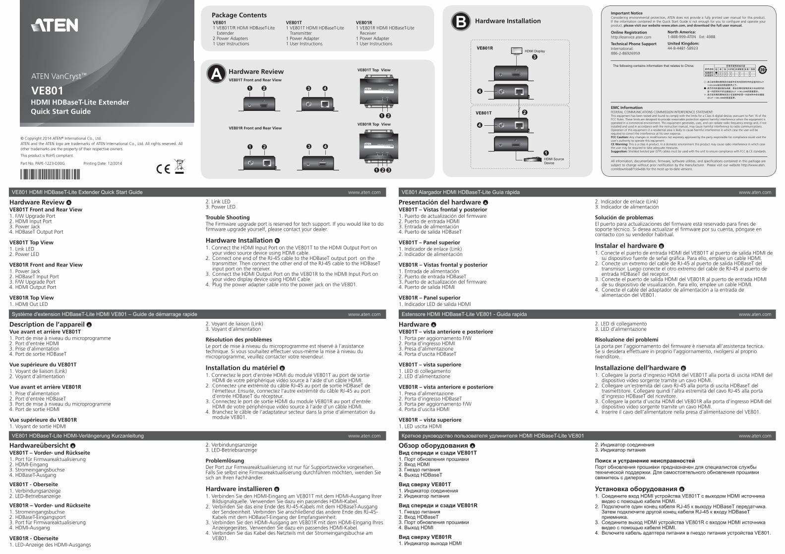
Hardware Review A VE801T Front and Rear View1. F/W Upgrade Port2. HDMI Input Port 3. Power Jack4. HDBaseT Output Port
VE801T Top View1. Link LED2. Power LED
VE801R Front and Rear View1. Power Jack2. HDBaseT Input Port 3. F/W Upgrade Port4. HDMI Output Port
VE801R Top View1. HDMI Out LED
Presentación del hardware A VE801T – Vistas frontal y posterior1. Puerto de actualización del fi rmware2. Puerto de entrada HDMI 3. Entrada de alimentación4. Puerto de salida HDBaseT
VE801T – Panel superior1. Indicador de enlace (Link)2. Indicador de alimentación
VE801R – Vistas frontal y posterior1. Entrada de alimentación2. Puerto de entrada HDBaseT 3. Puerto de actualización del fi rmware4. Puerto de salida HDMI VE801R – Panel superior1. Indicador LED de salida HDMI
Description de l’appareil A Vue avant et arrière VE801T1. Port de mise à niveau du microprogramme2. Port d’entrée HDMI 3. Prise d’alimentation4. Port de sortie HDBaseT
Vue supérieure du VE801T1. Voyant de liaison (Link)2. Voyant d’alimentation
Vue avant et arrière VE801R1. Prise d’alimentation2. Port d’entrée HDBaseT 3. Port de mise à niveau du microprogramme4. Port de sortie HDMI Vue supérieure du VE801R1. Voyant de sortie HDMI
Hardware A VE801T – vista anteriore e posteriore1. Porta per aggiornamento F/W2. Porta d’ingresso HDMI 3. Presa d’alimentazione4. Porta d’uscita HDBaseT
VE801T – vista superiore1. LED di collegamento2. LED d’alimentazione
VE801R – vista anteriore e posteriore1. Presa d’alimentazione2. Porta d’ingresso HDBaseT 3. Porta per aggiornamento F/W4. Porta d’uscita HDMI VE801R – vista superiore1. LED uscita HDMI
Hardwareübersicht A VE801T – Vorder- und Rückseite1. Port für Firmwareaktualisierung2. HDMI-Eingang 3. Stromeingangsbuchse4. HDBaseT-Ausgang
VE801T - Oberseite1. Verbindungsanzeige2. LED-Betriebsanzeige
VE801R – Vorder- und Rückseite1. Stromeingangsbuchse2. HDBaseT-Eingangsport 3. Port für Firmwareaktualisierung4. HDMI-Ausgang VE801R - Oberseite1. LED-Anzeige des HDMI-Ausgangs
Обзор оборудования A Вид спереди и сзади VE801T1. Порт обновления прошивки2. Вход HDMI3. Гнездо питания4. Выход HDBaseT
Вид сверху VE801T1. Индикатор соединения2. Индикатор питания
Вид спереди и сзади VE801R1. Гнездо питания2. Вход HDBaseT3. Порт обновления прошивки4. Выход HDMI
Вид сверху VE801R1. Индикатор выхода HDMI
2. Link LED3. Power LED
Trouble ShootingThe Firmware upgrade port is reserved for tech support. If you would like to do fi rmware upgrade yourself, please contact your dealer.
Hardware Installation B 1. Connect the HDMI Input Port on the VE801T to the HDMI Output Port on
your video source device using HDMI cable.2. Connect one end of the RJ-45 cable to the HDBaseT output port on the
transmitter. Then connect the other end of the RJ-45 cable to the HDBaseT input port on the receiver.
3. Connect the HDMI Output Port on the VE801R to the HDMI Input Port on your video display device using HDMI Cable.
4. Plug the power adapter cable into the power jack on the VE801.
2. Indicador de enlace (Link)3. Indicador de alimentación
Solución de problemasEl puerto para actualizaciones del fi rmware está reservado para fi nes de soporte técnico. Si desea actualizar el fi rmware por su cuenta, póngase en contacto con su vendedor habitual.
Instalar el hardware B 1. Conecte el puerto de entrada HDMI del VE801T al puerto de salida HDMI de
su dispositivo fuente de señal gráfi ca. Para ello, emplee un cable HDMI.2. Conecte un extremo del cable de RJ-45 al puerto de salida HDBaseT del
transmisor. Luego conecte el otro extremo del cable de RJ-45 al puerto de entrada HDBaseT del receptor.
3. Conecte el puerto de salida HDMI del VE801R al puerto de entrada HDMI de su dispositivo de visualización. Para ello, emplee un cable HDMI.
4. Conecte el cable del adaptador de alimentación a la entrada de alimentación del VE801.
2. Voyant de liaison (Link)3. Voyant d’alimentation
Résolution des problèmesLe port de mise à niveau du microprogramme est réservé à l’assistance technique. Si vous souhaitez effectuer vous-même la mise à niveau du microprogramme, veuillez contacter votre revendeur.
Installation du matériel B 1. Connectez le port d’entrée HDMI du module VE801T au port de sortie
HDMI de votre périphérique vidéo source à l’aide d’un câble HDMI.2. Connectez une extrémité du câble RJ-45 au port de sortie HDBaseT de
l’émetteur. Ensuite, connectez l’autre extrémité du câble RJ-45 au port d’entrée HDBaseT du récepteur.
3. Connectez le port de sortie HDMI du module VE801R au port d’entrée HDMI de votre périphérique vidéo source à l’aide d’un câble HDMI.
4. Branchez le câble de l’adaptateur secteur dans la prise d’alimentation du module VE801.
2. LED di collegamento3. LED d’alimentazione
Risoluzione dei problemiLa porta per l’aggiornamento del fi rmware è riservata all’assistenza tecnica. Se si desidera effettuare in proprio l’aggiornamento, rivolgersi al proprio rivenditore.
Installazione dell’hardware B 1. Collegare la porta d’ingresso HDMI del VE801T alla porta di uscita HDMI del
dispositivo video sorgente tramite un cavo HDMI.2. Collegare un’estremità del cavo RJ-45 alla porta di uscita HDBaseT del
trasmettitore. Collegare quindi l’altra estremità del cavo RJ-45 alla porta d’ingresso HDBaseT del ricevitore.
3. Collegare la porta d’uscita HDMI del VE801R alla porta d’ingresso HDMI del dispositivo video sorgente tramite un cavo HDMI.
4. Inserire il cavo dell’alimentatore nella presa d’alimentazione del VE801.
2. Verbindungsanzeige3. LED-Betriebsanzeige
ProblemlösungDer Port zur Firmwareaktualisierung ist nur für Supportzwecke vorgesehen. Falls Sie selbst eine Firmwareaktualisierung durchführen möchten, wenden Sie sich an Ihren Fachhändler.
Hardware installieren B 1. Verbinden Sie den HDMI-Eingang am VE801T mit dem HDMI-Ausgang Ihrer
Bildsignalquelle. Verwenden Sie dazu ein passendes HDMI-Kabel.2. Verbinden Sie das eine Ende des RJ-45-Kabels mit dem HDBaseT-Ausgang
der Sendeeinheit. Verbinden Sie anschließend das andere Ende des RJ-45-Kabels mit dem HDBaseT-Eingang der Empfangseinheit.
3. Verbinden Sie den HDMI-Ausgang am VE801R mit dem HDMI-Eingang Ihres Anzeigegerätes. Verwenden Sie dazu ein passendes HDMI-Kabel.
4. Verbinden Sie das Kabel des Netzteils mit der Stromeingangsbuchse am VE801.
2. Индикатор соединения3. Индикатор питания
Поиск и устранение неисправностейПорт обновления прошивки предназначен для специалистов службы технической поддержки. Для самостоятельного обновления прошивки свяжитесь с дилером.
Установка оборудования B 1. Соедините вход HDMI устройства VE801T с выходом HDMI источника
видео с помощью кабеля HDMI.2. Подключите один конец кабеля RJ-45 к выходу HDBaseT передатчика.
Затем подключите другой конец кабеля RJ-45 к входу HDBaseT приемника.
3. Соедините выход HDMI устройства VE801R с входом HDMI источника видео с помощью кабеля HDMI.
4. Включите кабель адаптера питания в гнездо питания устройства VE801.
A Hardware Review
B Hardware Installation
© Copyright 2014 ATEN® International Co., Ltd.ATEN and the ATEN logo are trademarks of ATEN International Co., Ltd. All rights reserved. All other trademarks are the property of their respective owners.
This product is RoHS compliant.
Part No. PAPE-1223-D30G Printing Date: 12/2014
HDMI HDBaseT-Lite ExtenderQuick Start Guide
VE801 ATEN VanCryst™
VE8011 VE801T/R HDMI HDBaseT-Lite
Extender2 Power Adapters1 User Instructions
VE801T 1 VE801T HDMI HDBaseT-Lite
Transmitter1 Power Adapter1 User Instructions
VE801R 1 VE801R HDMI HDBaseT-Lite
Receiver1 Power Adapter1 User Instructions
HDMI Source Device
VE801R
VE801T
HDMI Display
1
2
3
4
4
Important NoticeConsidering environmental protection, ATEN does not provide a fully printed user manual for this product. If the information contained in the Quick Start Guide is not enough for you to confi gure and operate your product, please visit our website www.aten.com, and download the full user manual.
Online Registrationhttp://eservice.aten.com
Technical Phone SupportInternational:886-2-86926959
All information, documentation, fi rmware, software utilities, and specifi cations contained in this package are subject to change without prior notifi cation by the manufacturer. Please visit our website http://www.aten.com/download/?cid=dds for the most up-to-date versions.
EMC InformationFEDERAL COMMUNICATIONS COMMISSION INTERFERENCE STATEMENT:This equipment has been tested and found to comply with the limits for a Class A digital device, pursuant to Part 15 of the FCC Rules. These limits are designed to provide reasonable protection against harmful interference when the equipment is operated in a commercial environment. This equipment generates, uses, and can radiate radio frequency energy and, if not installed and used in accordance with the instruction manual, may cause harmful interference to radio communications. Operation of this equipment in a residential area is likely to cause harmful interference in which case the user will be required to correct the interference at his own expense.FCC Caution: Any changes or modifi cations not expressly approved by the party responsible for compliance could void the user's authority to operate this equipment. CE Warning: This is a class A product. In a domestic environment this product may cause radio interference in which case the user may be required to take adequate measures.Suggestion: Shielded twisted pair (STP) cables must be used with the unit to ensure compliance with FCC & CE standards.
The following contains information that relates to China:
North America:1-888-999-ATEN Ext: 4988
United Kingdom:44-8-4481-58923
VE801T Front and Rear View
VE801R Front and Rear View
VE801T Top View
VE801R Top View
하드웨어 리뷰 A VE801T 전면과 후면
1. F/W 업그레이드 포트
2. HDMI 입력 포트
3. 전원잭
4. HDBaseT 출력 포트
VE801T 윗면
1. 링크 LED
2. 전원 LED
VE801R 전면과 후면
1. 전원잭
2. HDBaseT 입력 포트
3. F/W 업그레이드 포트
4. HDMI 출력 포트
Revisão do hardware A Visões frontal e traseira do VE801T1. Porta de atualização do firmware2. Porta de entrada HDMI 3. Conector de energia4. Portas de saída HDBaseT
Visão superior do VE801T1. LED de conexão2. LED de energia
Visões frontal e traseira do VE801R1. Conector de energia2. Porta de entrada HDBaseT 3. Porta de atualização do firmware4. Porta de saída HDMI Visão superior do VE801R1. LED de saída HDMI2. LED de conexão3. LED de energia
Огляд обладнання A Вигляд спереду та ззаду VE801T1. Порт оновлення мікропрограми2. Вхід HDMI3. Гніздо живлення4. Вихід HDBaseT
Вигляд згори VE803T1. Індикатор з’єднання2. Індикатор живлення
Вигляд спереду та ззаду VE801R1. Гніздо живлення2. Вхід HDBaseT3. Порт оновлення мікропрограми4. Вихід HDMI Вигляд згори VE801R1. Індикатор виходу HDMI2. Індикатор з’єднання3. Індикатор живлення
製品各部名称 A VE801T フロントおよびリアパネル1. F/Wアップグレードポート2. HDMI入力ポート3. 電源ジャック4. HDBaseT出力ポート
VE801Tトップパネル1. リンクLED2. 電源LED
VE801Rフロントおよびリアパネル1. 電源ジャック2. HDBaseT入力ポート3. ファームウェアアップグレードポート4. HDMI出力ポート VE801Rトップパネル1. HDMI出力LED2. リンクLED3. 電源LED
VE801R 윗면
1. HDMI 출력 LED
2. 링크 LED
3. 전원 LED
문제 해결
펌웨어 업그레이드 포트는 기술 지원을 위해 사용됩니다. 펌웨어 업그
레이드 필요 시 대리점에 문의하세요.
하드웨어 설치 B 1. VE801T에 있는 HDMI 입력 포트를 HDMI케이블을 이용하여 비디오
소스에 있는 HDMI 출력 포트에 연결합니다.
2. RJ-45 케이블의 한 쪽을 전송기의 HDBaseT 출력 포트에
연결합니다. 그런 다음 RJ-45케이블의 다른 한 쪽을 수신기에 있는
HDBaseT입력 포트에 연결합니다.
3. VE801R 에 있는 HDMI 출력 포트를 HDMI 케이블을 이용하여
비디오 디스플레이 장치에 있는 HDMI 입력 포트에 연결합니다.
4. VE801에 있는 전원잭에 전원 어댑터를 연결합니다.
Solução de problemasA porta de atualização de firmware é reservada para suporte técnico. Caso queira atualizar o firmware você mesmo, entre em contato com seu fornecedor.
Instalação de hardware B 1. Conecte a porta de entrada HDMI do VE801T à porta de saída HDMI do
dispositivo de fonte de vídeo usando um cabo HDMI.2. Conecte uma ponta do cabo RJ-45 à porta de saída HDBaseT do transmissor.
Em seguida, conecte a outra ponta do cabo RJ-45 à porta de entrada HDBaseT do receptor.
3. Conecte a porta de saída HDMI do VE801R à porta de entrada HDMI do monitor usando um cabo HDMI.
4. Conecte o cabo do adaptador de energia ao conector de energia do VE801.
Пошук та усунення несправностейПорт оновлення мікропрограми призначений для спеціалістів служби технічної підтримки. Для самостійного оновлення мікропрограми звертайтесь до дилера.
Встановлення обладнання B 1. Підключіть вхід HDMI пристрою VE801T до виходу HDMI джерела відео
за допомогою кабелю HDMI.2. Підключіть один кінець кабелю RJ-45 до виходу HDBaseT передавача.
Потім підключіть інший кінець кабелю RJ-45 до входу HDBaseT приймача.
3. Підключіть вихід HDMI пристрою VE801R до виходу HDMI пристрою відображення за допомогою кабелю HDMI.
4. Підключіть кабель адаптер живлення до гнізда живлення на VE801.
トラブルシューティングファームウェアアップグレードポートはテクニカルサポート用の予備ポートになっています。ご自身でファームウェアをアップグレードされたい場合は、販売代理店までお問い合わせください。
ハードウェアのセットアップ B 1. HDMIケーブルを使用して、VE801TのHDMI入力ポートとビデオソースデバイスのHDMI出力ポートを接続してください。
2. RJ-45ケーブルを使用して、VE801T(トランスミッター)のHDBaseT出力ポートとVE801R(レシーバー)のHDBaseT入力ポートを接続してください。
3. HDMIケーブルを使用して、VE801RのHDMI出力ポートとビデオディスプレイデバイスを接続してください。
4. VE801TとVE801Rそれぞれの電源ジャックに電源アダプターを接続してください。
Короткий посібник користувача подовжувача HDMI HDBaseT-Lite VE801
Guia de início rápido do extensor HDMI HDBaseT-Lite VE801
VE801 HDBaseT-Lite HDMIエクステンダー クイックスタートガイド
VE801 HDMI HDBaseT-Lite 연장기 빠른 시작 가이드www.aten.com
www.aten.com
www.aten.com サポートお問合せ窓口:+81-3-5615-5811
www.aten.com Phone: 02-467-6789


![MANUALE DELL’UTENTE - de.gopro.com · Porta HERO / Operazioni di base 5. Pulsante Accensione/ Modalità [ ] Porta Micro HDMI ... informazioni sulle modalità e sulle impostazioni](https://static.fdocumenti.com/doc/165x107/6012e33feae85443a14d4423/manuale-dellautente-degoprocom-porta-hero-operazioni-di-base-5-pulsante.jpg)