
USER’S -INSTALLER’S MANUAL - wodalodowa.com V4.pdf · Norme armonizzate applicate alla...
40
CHILLERS AND INVERTER AIR/WATER HEAT PUMPS WITH AXIAL FANS A I R C O N D I T I O N I N G A47 USER’S -INSTALLER’S MANUAL Serie/Series/Serie/Série Emissione/Edition/Au- sgabeIssue i-HWAK V4 06 ÷ 14(T)/16T Catalogo/Catalogue/Katalog/Brochure Sostituisce/Superseedes Ersetzt/Remplace MUI01124H7820-03 07 – 2017 R410a 07 – 2017
Transcript of USER’S -INSTALLER’S MANUAL - wodalodowa.com V4.pdf · Norme armonizzate applicate alla...
CHILLERS AND INVERTER AIR/WATER HEAT PUMPS WITH AXIAL FANS
A I R C O N D I T I O N I N G
A47
US
ER
’S -
INS
TA
LL
ER
’S M
AN
UA
L
Serie/S
erie
s/Serie/S
érie
Emissione/
Edi
tion/Au-
sgabeI
ssue
i-H
WA
K V
4 0
6 ÷
14(T
)/1
6T
Catalogo/
Cat
alog
ue/Katalog/B
roch
ure
Sostituisce/
Sup
erse
edes
Ersetzt/R
empl
ace
MUI01124H7820-03
07
– 2
017
R22
R407c
R410a
R134a
R407C
07
– 2
017
i-HWAK V4 Chillers and inverter air / water heat pumps with axial fans
2
03 07-17 AL.B P.F. Updating of wiring diagrams of the three-phase units
02 07-17 AL.B P.F. Updating of technical data and wiring diagrams
01 02-17 AL.B A.B. Updating of Envelope, Conformity, Head pressure curves, technical data, wiring diagram
00 01-17 AL.B. A.B. First edition Rev Date Author Supervisor Notes
Catalogo / Catalogue / Katalog / Catalogue
MUI01124H7820-03Serie / Series / Serie / Serie / Série
CHILLERS AND INVERTER AIR/WATER HEAT PUMPS WITH AXIAL FANS Possible wasted electrical or electronic devices/products should not be located together with normal domestic waste, but disposed according to the
current WEEE law in compliance with the European Directive 2012/19/UE. Please inform yourself at your local Administration or at your reseller in case the product will be replaced with a similar one.
i-HWAK V4 Chillers and inverter air / water heat pumps with axial fans
3
CE CONFORMITY DECLARATION
DICHIARAZIONE DI CONFORMITÁ CE
THE COMPANY ADVANTIX S.P.A – VIA SAN GIUSEPPE LAVORATORE, 24 – LOC. LA MACIA Z.A.I. – 37040 – ARCOLE - VERONA - ITALY
LA SOCIETÀ ADVANTIX S.P.A – VIA SAN GIUSEPPE LAVORATORE, 24 – LOC. LA MACIA Z.A.I. – 37040 – ARCOLE - VERONA - ITALY
DECLARES DICHIARA
that the unit: che la macchina:
Definition : Definizione :
Chiller and inverter air/water heat pumps with axial fans / Refrigeratori e pompe di calore inverter aria/acqua con ventilatori assiali
Model N° : N° modello :
i-HWAK/V4 06 / 08 / 10 / 12 / 14 / 14T / 16T i-HWAK/V4/KA 06 / 08 / 10 / 12 / 14 / 14T / 16T
Serie N°: N° di serie:
MEETS THE REQUIREMENTS OF DIRECTIVE 2006/42/CE È CONFORME AI REQUISITI DELLA DIRETTIVA 2006/42/CE
1. The unit is in CAT. I, so it’s free from the application of Directive 2014/68/UE (Reference to Art. I, paragraph 2, point f) L’attrezzatura a pressione rientra nella CAT. I. L’unità è quindi esente dall’applicazione della normativa PED 2014/68/UE (Riferimento Art. I, paragrafo 2 punto f). 2. Harmonized standards applied to designing and manufacture : UNI EN 378-1, UNI EN378-2, UNI EN 12735-1 Norme armonizzate applicate alla progettazione ed alla costruzione : UNI EN 378-1, UNI EN378-2, UNI EN 12735-1 3. Others European Directives and harmonized standards applied to the equipment : 2014/35/UE, 2014/30/UE, 2011/65/UE, 2012/19/UE, CEI EN 60335-2-40, CEI EN 55014-1, CEI EN 55014-2, CEI EN 61000-3-2, CEI EN 61000-3-3, CEI EN 62233 Eventuali altre Direttive Europee e norme armonizzate applicate all’attrezzatura : 2014/35/UE, 2014/30/UE, 2011/65/UE, 2012/19/UE, CEI EN 60335-2-40, CEI EN 55014-1, CEI EN 55014-2, CEI EN 61000-3-2, CEI EN 61000-3-3, CEI EN 62233 The manufacturer states, also, that the technical file is compiled and kept at ADVANTIX SpA and that the Technical Manager Paolo Ferroli is the person authorized to compile it. Il fabbricante inoltre dichiara che il fascicolo tecnico della macchina è costituito e custodito presso ADVANTIX SpA e che il Direttore Tecnico Paolo Ing. Ferroli è la persona autorizzata a costituire tale fascicolo. Arcole, Gennaio/January 2017 Advantix S.p.a. Paolo Ing. Ferroli
i-HWAK V4 Chillers and inverter air / water heat pumps with axial fans
4
INDEX 1 PURPOSE AND CONTENT OF THE MANUAL ............................................................................................................................ 6
1.1 CONSERVATION OF THE MANUAL .......................................................................................................................................... 6 1.2 GRAPHIC SYMBOLS ................................................................................................................................................................. 6
2 SAFETY LAWS ......................................................................................................................................................................... 6
3 PERMITTED USES ................................................................................................................................................................... 7
4 GENERAL SAFETY GUIDELINES ................................................................................................................................................ 7
4.1 WORKERS’ HEALTH AND SAFETY ............................................................................................................................................ 7 4.2 PERSONAL SAFETY EQUIPMENTS ........................................................................................................................................... 8 4.3 SAFETY SYMBOLS .................................................................................................................................................................... 8 4.4 REFRIGERANT SAFETY DATA SHEET ........................................................................................................................................ 9
5 TECHNICAL CHARACTERISTICS .............................................................................................................................................. 10
5.1 FRAME .................................................................................................................................................................................. 10 5.2 REFRIGERANT CIRCUIT ......................................................................................................................................................... 10 5.3 COMPRESSORS ..................................................................................................................................................................... 10 5.4 AIR SIDE EXCHANGERS .......................................................................................................................................................... 10 5.5 FANS ..................................................................................................................................................................................... 10 5.6 USER SIDE HEAT EXCHANGERS ............................................................................................................................................. 10 5.7 ELECTRIC BOX ....................................................................................................................................................................... 10 5.8 CONTROL SYSTEM ................................................................................................................................................................ 10 5.9 MONITORING AND PROTECTION DEVICES ........................................................................................................................... 11 5.10 HYDRAULIC CIRCUIT ............................................................................................................................................................. 11 5.11 FAN SPEED CONTROL............................................................................................................................................................ 11
6 AVAILABLE VERSIONS .......................................................................................................................................................... 11
6.1 OPTIONAL ACCESSORIES ...................................................................................................................................................... 12
7 INSTALLATION ...................................................................................................................................................................... 13
7.1 GENERALITY .......................................................................................................................................................................... 13 7.2 LIFTING AND HANDLING ....................................................................................................................................................... 13 7.3 LOCATION AND MINIMUM TECHNICAL CLEARANCES .......................................................................................................... 13 CAUTION: IS IS OBLIGATORY TO INSTALL THE UNIT ON A FIRM AND APPROPRIATE BASEMENT TO SUPPORT ITS WEIGHT. CONSIDERING THE WEIGHT OF THE UNIT, POSSIBLE VIBRATIONS AND RESULTANT NOISE, WE DO NOT RECOMMEND SUSPENSION INSTALLION OF THE UNIT; IN THIS CASE, THE FIRM IS NOT RESPONSIBLE FOR ANY DAMAGE OR INCONVENIENCE THAT MAY RESULT............................................................................................................ 14 7.4 HYDRAULIC CONNECTIONS .................................................................................................................................................. 14
7.4.1 Drainage connection .................................................................................................................................................... 14 7.4.2 Plant circuit charging.................................................................................................................................................... 14 7.4.3 Plant drainage system .................................................................................................................................................. 15 7.4.4 Hydraulic circuit ............................................................................................................................................................ 15
7.5 REFRIGERANT DIAGRAM OF 06-08 ....................................................................................................................................... 16 7.6 REFRIGERANT DIAGRAM OF 10-12 ....................................................................................................................................... 16 7.7 REFRIGERANT DIAGRAM OF 14-16 ....................................................................................................................................... 16 7.8 ELECTRICAL CONNECTIONS .................................................................................................................................................. 16
7.8.1 Wiring terminal block ................................................................................................................................................... 17 7.8.2 Terminal block and the electric box .............................................................................................................................. 18
8 START UP ............................................................................................................................................................................. 18
9 SHUTDOWNS FOR LONG PERIODS........................................................................................................................................ 19
10 MAINTENANCE AND PERIODICAL CONTROLS ................................................................................................................... 19
10.1 ENVIRONMENTAL PROTECTION ........................................................................................................................................... 20
11 APPLIANCE RECYCLING ..................................................................................................................................................... 20
12 TECHNICAL DATA.............................................................................................................................................................. 21
13 ELECTRIC DATA OF THE UNIT AND AUXILIARIES ............................................................................................................... 22
14 HYDRAULIC CIRCUIT AVAILABLE HEAD PRESSURE ............................................................................................................ 23
i-HWAK V4 Chillers and inverter air / water heat pumps with axial fans
5
15 OPERATION LIMITS .......................................................................................................................................................... 25
15.1 EVAPORATOR WATER FLOW RATE ....................................................................................................................................... 25 15.2 COLD WATER TEMPERATURE (SUMMER OPERATION) ......................................................................................................... 25 15.3 HOT WATER TEMPERATURE (WINTER OPERATION) ............................................................................................................. 25 15.4 AMBIENT AIR TEMPERATURE AND SUMMARIZING TABLES ................................................................................................. 25
16 CORRECTION FACTORS FOR USE OF GLYCOL .................................................................................................................... 27
17 DIMENSIONS .................................................................................................................................................................... 27
17.1 MODELS I-HWAK V4 06/08 ................................................................................................................................................... 27 17.2 MODELS I -HWAK V4 10/12................................................................................................................................................... 27 17.3 MODELS I-HWAK V4 14 /14T / 16T ........................................................................................................................................ 28 17.4 INTERNAL PARTS OF THE UNIT ............................................................................................................................................. 28
17.4.1 Mod. i-HWAK V4 06 / 08 .............................................................................................................................................. 28 17.4.2 Mod. i-HWAK V4 10 / 12 .............................................................................................................................................. 29 17.4.3 Mod. i-HWAK V4 14 / 14T / 16T ................................................................................................................................... 29
18 WIRING DIAGRAMS .......................................................................................................................................................... 30
18.1 MODELS I-HWAK V4 06 / 08 / 10 / 12 .................................................................................................................................... 30 18.2 MODELS I-HWAK V4 14 ......................................................................................................................................................... 33 18.3 MODEL I-HWAK V4 14T / 16T ................................................................................................................................................ 36
19 HYDRAULIC DIAGRAM TYPE ............................................................................................................................................. 39
20 CONTROL LOGICS ............................................................................................................................................................. 39
21 HANDBOOK FOR CONFIGURATIONS OF SOME INSTALLATIONS ........................................................................................ 39
i-HWAK V4 Chillers and inverter air / water heat pumps with axial fans
6
The manual of i-HWAK V4 units contains all the necessary information for the better use of the equipment under safety conditions for the operator thus meeting the requirements listed in the 2006/42/CE Equipment Directive and following amendments.
1 PURPOSE AND CONTENT OF THE MANUAL This manual provides basic information as for the installation, the operation and the maintenance of the i-HWAK V4 units. It is addressed to machine operators and it enables them to use the equipment efficiently, even if they do not have any previous specific knowledge of it.
WARNING: Although this manual is also destined for the end-user utilizations, some discibed activities are allowed only for trained technical personnels who should be in possession of Vocational and Technical Training allowing them to be responsible for carrying out the activity. They should be properly updated with courses approved by the competent authorities. These activities includ: installation, both ordinary and extraordinary maintenance, appliance disposal and any other activity required by "qualified staff." After the end of installation and/or maintenance of the appliance, the qualified operator has a duty to properly inform the end-user about the use of the appliance and the necessary periodical checks. The installer is responsible to deliver all necessary documentation (including this manual) to the user and should ensure him to keep it in a safe place near the appliance where it can be available at any time.
This manual describes the characteristics of the equipment at the time in which it is being put on the market; therefore, it may not include technological improvements introduced later by the company as part of its constant endeavour to enhance the performance, ergonomics, safety and functionality of its products. The company, therefore, is not constrained to update the manuals for previous versions of machines. It’s recommended that, the user must follow the instructions contained in this booklet, especially those concerning the safety and routine maintenance.
1.1 CONSERVATION OF THE MANUAL The manual has to be always kept by the user for future reference. It has to be stored in a safe place, away from dusts and moisture. It has to be available and accessible to all users who shall consult it when they are in doubt on how to operate the equipment. The company reserves the right to modify its products and related manuals without necessarily updating previous versions of the reference material. It declines also any responsibility for possible inaccuracies in the manual if due to printing or transcription errors. The customer shall store any updated copy of the manual or parts of it delivered by the manufacturer as an attachment to this manual. The company is available to give any detailed information about this manual and to give information regarding the use and the maintenance of its own units.
1.2 GRAPHIC SYMBOLS
Indicates operations that can be dangerous for people and/or disrupts the correct operation of the equipment.
Indicates prohibited operations.
Indicates important information that the operator has to follow in order to guarantee the correct operation of the equipment in complete safety.
2 SAFETY LAWS The i-HWAK V4 units have been designed in compliance with the following Directives and Harmonised Norms concerning the safety of the appliances: x 97/23/CE, 2014/35/UE, 2014/30/UE, 2011/65/UE, 2012/19/UE Community Directives x UNI EN 378-1, 378-2, UNI EN 12735-1 Norms x CEI EN 60335-2-40 Norms x CEI EN 55014-1, CEI EN 55014-2, CEI EN 61000-3-2, CEI EN 61000-3-3, CEI EN 62233 Norms And the following directives and regulations concerning the energy labeling and the eco-friendly products: x Community directive 2009/125/CE and subsequent transpositions x Community directive 2010/30/UE and subsequent transpositions x Regulation UE No 811/2013 x Regulation UE No 813/2013
i-HWAK V4 Chillers and inverter air / water heat pumps with axial fans
7
3 PERMITTED USES x The company excludes any contractual and extra contractual liabilities for damages caused to persons, animals or objects, by
incorrect installation, setting and maintenance, improper use of the equipment, and the partial or superficial reading of the information contained in this manual.
x These units have been designed only for heating and/or cooling water. Any other use not expressly authorized by the manufacturer is considered improper and therefore not allowed.
x The location of the plant, the hydraulic and electrical circuits must be established by the planting designer and must take into account both technical requirements as well as any applicable local laws and authorized specifications.
x The execution of all works must be performed by skilled and qualified personnel, competent in the existing rules in different countries.
4 GENERAL SAFETY GUIDELINES Before beginning to operate on i-HWAK V4 units every user has to be perfectly knowledgeable about the functions of the equipment and its controls and has to have read and understood the information listed in this manual.
It’s strictly forbidden to remove and/or tamper with any safety device. Children or unassisted disabled persons are not allowed to use the appliance. Do not touch the appliance when barefoot or parts of the body are wet or damp. Do not clean the unit when the power is ‘ON’. Do not pull, remove or twist the electrical cables coming out from the unit, even if it is disconnected from the main power supply. Do not step with your feet on the appliance, sit down and/or place any type of object. Do not spray or pour water directly on the unit. Do not dispose of, abandon or leave within reach of children packaging materials (cardboard, staples, plastic bags, etc.) as they may represent a hazard.
Any routine or not-routine maintenance operation shall be carried out when the equipment has been shut down, disconnected from electric power sources. Do not put neither your hands nor insert screwdrivers, spanners or other tools into moving parts of the equipment. The equipment supervisor and the maintenance man have to receive suitable training for the performance of their tasks in safety. Operators have to know how to use personal protective devices and have to know the accident-prevention guidelines contained in national and international laws and norms.
4.1 WORKERS’ HEALTH AND SAFETY The European Community has adopted a number of directives on workplace’s health and safety, which are 89/391/CEE, 89/686/CEE, 2009/104/CE, 86/188/CEE and 77/576/CEE directives, and the subsequent integrations/modification. Every employer shall implement such provisions and ensure that their workers to respect them. We observe therefore that:
Do not tamper with or replace parts of the equipment without the specific consent of the manufacturer. The manufacturer shall have no responsibility whatsoever in case of unauthorised operations.
Using components, expendable materials or spare parts that do not correspond to those recommended by the manufacturer and/or listed in this manual may be dangerous for the operators and/or damage the equipment
The operator’s workplace has to be kept clean, tidy and free from objects that may prevent free movements. Appropriate lighting of the work place shall be provided so as to allow the operator to carry out the required operations safely. Poor or too strong lighting can cause risks.
Ensure that work places are always adequately ventilated and that aspirators are working, in good condition and in compliance with the requirements of the laws in force.
The unit operates with R410A refrigerant gas, which is a greenhouse gas according to the F-gas Regulation (EU) 517/2014 (mandatory in the European area). This Regulation, among the provisions, requires all operators intervening in greenhouse gas systems to be in possession of a certificate issued or recognized by the competent authority, attesting to a successful completion of an examination entitling them to carry out such work. In particular:
¾ Device contains up to 3kg of the total amount of refrigerant gas: Category II certificate. ¾ Device contains 3kg or more than 3kg of the total amount of refrigerant gas: Category I certificate.
The refrigerant R410A in gaseous form is heavier than air and tends to concentrate highly in little ventilated environments when a leak occurs. Its inhalation can cause dizziness, suffocation and can develop lethal gas if it becomes in contact with open flames or hot objects, (please see “REFRIGERANT SAFETY DATA SHEET” paragraph 4.4).
i-HWAK V4 Chillers and inverter air / water heat pumps with axial fans
8
For any intervention on the heat pump:
Wear appropriate Personal Protective Equipment (PPE) specifically, gloves and goggles.
Ensure that the workplace is well ventilated. Do not work in closed rooms or ditches with weak air circulation.
Do not work on the refrigerant near open flames or near hot parts.
Avoid any refrigerant leakage into the environment and pay particular attention to leakage from pipes and/or fittings after evacuating the refrigerant circuit.
4.2 PERSONAL SAFETY EQUIPMENTS
When operating and maintaining the i-HWAK V4 units, use the following personal protective equipment.
Protective clothing: Maintenance men and operators have to wear protective clothing that complies with the basic safety requirements currently in force. In case of slippery floors, users have to wear safety shoes with non-slip soles.
Gloves: During maintenance or cleaning operation protection gloves have to be used
Mask and goggles: Respiratory protection (mask) and eye protection (goggles) should be used during cleaning and maintenance operations.
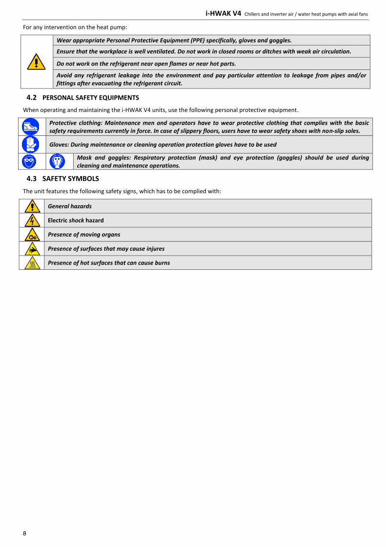
4.3 SAFETY SYMBOLS The unit features the following safety signs, which has to be complied with:
General hazards
Electric shock hazard
Presence of moving organs
Presence of surfaces that may cause injures
Presence of hot surfaces that can cause burns
i-HWAK V4 Chillers and inverter air / water heat pumps with axial fans
9
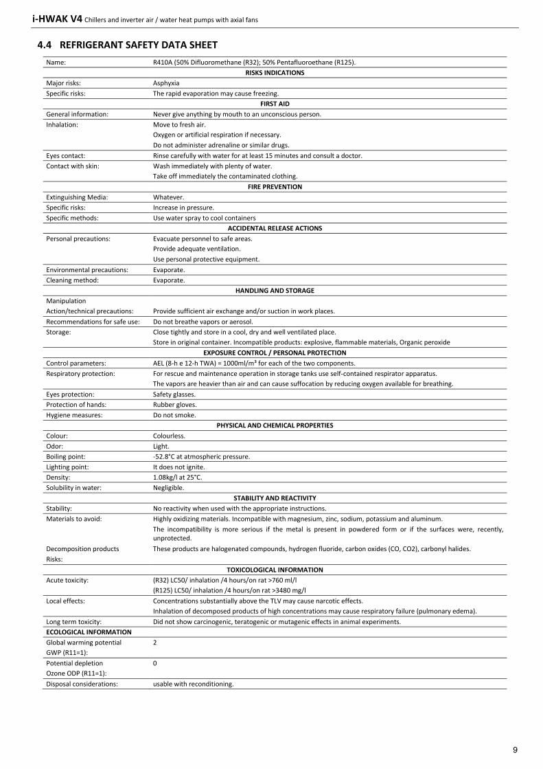
4.4 REFRIGERANT SAFETY DATA SHEET Name: R410A (50% Difluoromethane (R32); 50% Pentafluoroethane (R125).
RISKS INDICATIONS Major risks: Asphyxia Specific risks: The rapid evaporation may cause freezing.
FIRST AID General information: Never give anything by mouth to an unconscious person. Inhalation: Move to fresh air. Oxygen or artificial respiration if necessary. Do not administer adrenaline or similar drugs. Eyes contact: Rinse carefully with water for at least 15 minutes and consult a doctor. Contact with skin: Wash immediately with plenty of water. Take off immediately the contaminated clothing.
FIRE PREVENTION Extinguishing Media: Whatever. Specific risks: Increase in pressure. Specific methods: Use water spray to cool containers
ACCIDENTAL RELEASE ACTIONS Personal precautions: Evacuate personnel to safe areas. Provide adequate ventilation. Use personal protective equipment. Environmental precautions: Evaporate. Cleaning method: Evaporate.
HANDLING AND STORAGE Manipulation Action/technical precautions: Provide sufficient air exchange and/or suction in work places. Recommendations for safe use: Do not breathe vapors or aerosol. Storage: Close tightly and store in a cool, dry and well ventilated place. Store in original container. Incompatible products: explosive, flammable materials, Organic peroxide
EXPOSURE CONTROL / PERSONAL PROTECTION Control parameters: AEL (8-h e 12-h TWA) = 1000ml/m³ for each of the two components. Respiratory protection: For rescue and maintenance operation in storage tanks use self-contained respirator apparatus. The vapors are heavier than air and can cause suffocation by reducing oxygen available for breathing. Eyes protection: Safety glasses. Protection of hands: Rubber gloves. Hygiene measures: Do not smoke.
PHYSICAL AND CHEMICAL PROPERTIES Colour: Colourless. Odor: Light. Boiling point: -52.8°C at atmospheric pressure. Lighting point: It does not ignite. Density: 1.08kg/l at 25°C. Solubility in water: Negligible.
STABILITY AND REACTIVITY Stability: No reactivity when used with the appropriate instructions. Materials to avoid: Highly oxidizing materials. Incompatible with magnesium, zinc, sodium, potassium and aluminum.
The incompatibility is more serious if the metal is present in powdered form or if the surfaces were, recently, unprotected.
Decomposition products These products are halogenated compounds, hydrogen fluoride, carbon oxides (CO, CO2), carbonyl halides. Risks:
TOXICOLOGICAL INFORMATION Acute toxicity: (R32) LC50/ inhalation /4 hours/on rat >760 ml/l (R125) LC50/ inhalation /4 hours/on rat >3480 mg/l Local effects: Concentrations substantially above the TLV may cause narcotic effects. Inhalation of decomposed products of high concentrations may cause respiratory failure (pulmonary edema). Long term toxicity: Did not show carcinogenic, teratogenic or mutagenic effects in animal experiments. ECOLOGICAL INFORMATION Global warming potential 2 GWP (R11=1): Potential depletion 0 Ozone ODP (R11=1): Disposal considerations: usable with reconditioning.
i-HWAK V4 Chillers and inverter air / water heat pumps with axial fans
10
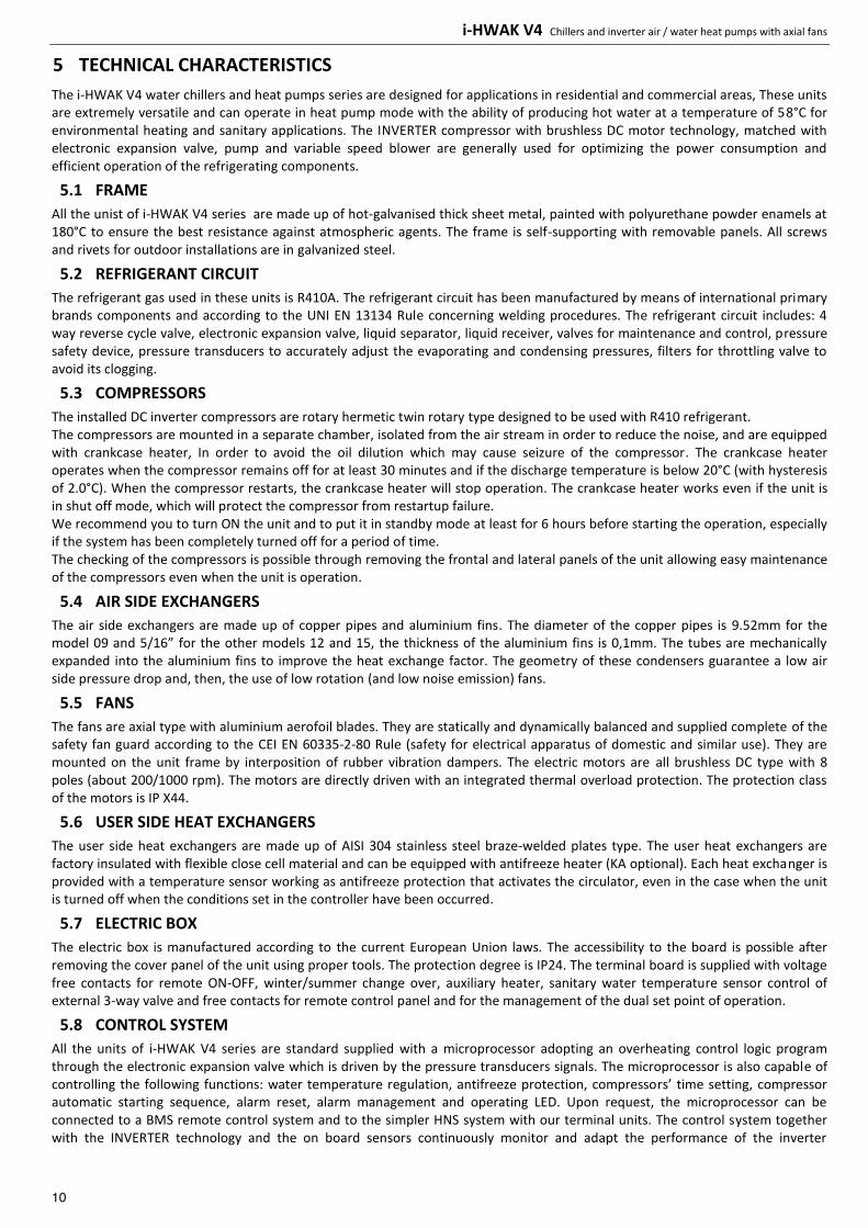
5 TECHNICAL CHARACTERISTICS The i-HWAK V4 water chillers and heat pumps series are designed for applications in residential and commercial areas, These units are extremely versatile and can operate in heat pump mode with the ability of producing hot water at a temperature of 58°C for environmental heating and sanitary applications. The INVERTER compressor with brushless DC motor technology, matched with electronic expansion valve, pump and variable speed blower are generally used for optimizing the power consumption and efficient operation of the refrigerating components.
5.1 FRAME All the unist of i-HWAK V4 series are made up of hot-galvanised thick sheet metal, painted with polyurethane powder enamels at 180°C to ensure the best resistance against atmospheric agents. The frame is self-supporting with removable panels. All screws and rivets for outdoor installations are in galvanized steel.
5.2 REFRIGERANT CIRCUIT The refrigerant gas used in these units is R410A. The refrigerant circuit has been manufactured by means of international primary brands components and according to the UNI EN 13134 Rule concerning welding procedures. The refrigerant circuit includes: 4 way reverse cycle valve, electronic expansion valve, liquid separator, liquid receiver, valves for maintenance and control, pressure safety device, pressure transducers to accurately adjust the evaporating and condensing pressures, filters for throttling valve to avoid its clogging.
5.3 COMPRESSORS The installed DC inverter compressors are rotary hermetic twin rotary type designed to be used with R410 refrigerant. The compressors are mounted in a separate chamber, isolated from the air stream in order to reduce the noise, and are equipped with crankcase heater, In order to avoid the oil dilution which may cause seizure of the compressor. The crankcase heater operates when the compressor remains off for at least 30 minutes and if the discharge temperature is below 20°C (with hysteresis of 2.0°C). When the compressor restarts, the crankcase heater will stop operation. The crankcase heater works even if the unit is in shut off mode, which will protect the compressor from restartup failure. We recommend you to turn ON the unit and to put it in standby mode at least for 6 hours before starting the operation, especially if the system has been completely turned off for a period of time. The checking of the compressors is possible through removing the frontal and lateral panels of the unit allowing easy maintenance of the compressors even when the unit is operation.
5.4 AIR SIDE EXCHANGERS The air side exchangers are made up of copper pipes and aluminium fins. The diameter of the copper pipes is 9.52mm for the model 09 and 5/16” for the other models 12 and 15, the thickness of the aluminium fins is 0,1mm. The tubes are mechanically expanded into the aluminium fins to improve the heat exchange factor. The geometry of these condensers guarantee a low air side pressure drop and, then, the use of low rotation (and low noise emission) fans.
5.5 FANS The fans are axial type with aluminium aerofoil blades. They are statically and dynamically balanced and supplied complete of the safety fan guard according to the CEI EN 60335-2-80 Rule (safety for electrical apparatus of domestic and similar use). They are mounted on the unit frame by interposition of rubber vibration dampers. The electric motors are all brushless DC type with 8 poles (about 200/1000 rpm). The motors are directly driven with an integrated thermal overload protection. The protection class of the motors is IP X44.
5.6 USER SIDE HEAT EXCHANGERS The user side heat exchangers are made up of AISI 304 stainless steel braze-welded plates type. The user heat exchangers are factory insulated with flexible close cell material and can be equipped with antifreeze heater (KA optional). Each heat exchanger is provided with a temperature sensor working as antifreeze protection that activates the circulator, even in the case when the unit is turned off when the conditions set in the controller have been occurred.
5.7 ELECTRIC BOX The electric box is manufactured according to the current European Union laws. The accessibility to the board is possible after removing the cover panel of the unit using proper tools. The protection degree is IP24. The terminal board is supplied with voltage free contacts for remote ON-OFF, winter/summer change over, auxiliary heater, sanitary water temperature sensor control of external 3-way valve and free contacts for remote control panel and for the management of the dual set point of operation.
5.8 CONTROL SYSTEM All the units of i-HWAK V4 series are standard supplied with a microprocessor adopting an overheating control logic program through the electronic expansion valve which is driven by the pressure transducers signals. The microprocessor is also capable of controlling the following functions: water temperature regulation, antifreeze protection, compressors’ time setting, compressor automatic starting sequence, alarm reset, alarm management and operating LED. Upon request, the microprocessor can be connected to a BMS remote control system and to the simpler HNS system with our terminal units. The control system together with the INVERTER technology and the on board sensors continuously monitor and adapt the performance of the inverter
i-HWAK V4 Chillers and inverter air / water heat pumps with axial fans
11
compressor, of the pump and of the fan (2 fans for the models: 14, 14T and 16T) according to the value of cooling power at any working conditions requested by the user.
5.9 MONITORING AND PROTECTION DEVICES All units are standard supplied with the following monitoring and protection devices: return water temperature sensor installed at the return water pipe line from the plant, operating and antifreeze sensor installed at the outlet pipe of the water to the plant, high pressure transducer, low pressure transducer, compressor’s inlet and outlet temperature sensors, compressors thermal protection device, fans thermal protection device, water side installed water flow switch to protect the evaporator, high pressure HP flow switch.
5.10 HYDRAULIC CIRCUIT The i-HWAK V4 chillers units are supplied with an integrated hydraulic circuit including: circulating pump with high efficiency DC brushless motor (EEI≤0,23 for the sizes 14 and 16 kW, however for 06, 08, 10 and 12 kW EEI≤0,20), suitable for chilled water utilization and directly run by a controller on board, plate heat exchanger, expansion vessel (The expansion vessel capacity depends on the size of the unit, refer to the technical data shown in chapter 12), safety valve (6 bar) that have to be connected with a colleting tank, the manual air release valve and the flow switch.
5.11 FAN SPEED CONTROL This type of control is managed by the microprocessor and is necessary for optimizing the pressure of evaporation/condensation during summer/winter operation in order to allow proper running of the unit.
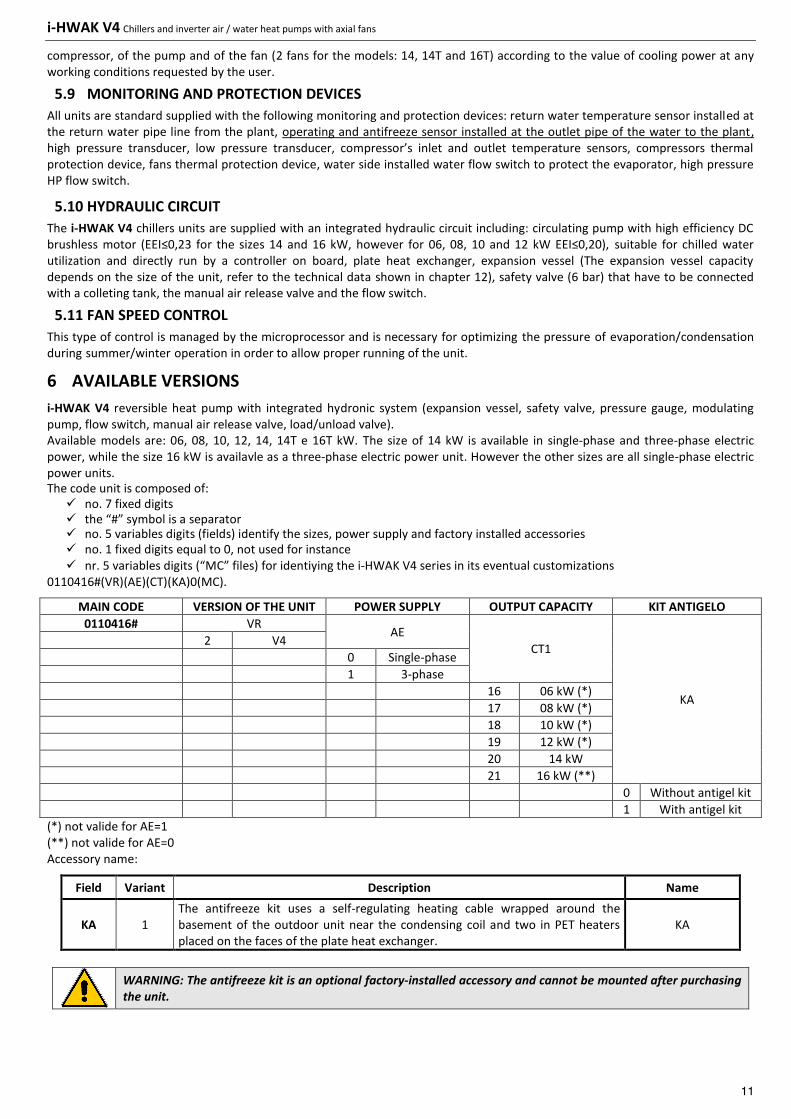
6 AVAILABLE VERSIONS i-HWAK V4 reversible heat pump with integrated hydronic system (expansion vessel, safety valve, pressure gauge, modulating pump, flow switch, manual air release valve, load/unload valve). Available models are: 06, 08, 10, 12, 14, 14T e 16T kW. The size of 14 kW is available in single-phase and three-phase electric power, while the size 16 kW is availavle as a three-phase electric power unit. However the other sizes are all single-phase electric power units. The code unit is composed of: 9 no. 7 fixed digits 9 the “#” symbol is a separator 9 no. 5 variables digits (fields) identify the sizes, power supply and factory installed accessories 9 no. 1 fixed digits equal to 0, not used for instance 9 nr. 5 variables digits (“MC” files) for identiying the i-HWAK V4 series in its eventual customizations
0110416#(VR)(AE)(CT)(KA)0(MC).
MAIN CODE VERSION OF THE UNIT POWER SUPPLY OUTPUT CAPACITY KIT ANTIGELO 0110416# VR
AE CT1
KA
2 V4 0 Single-phase 1 3-phase 16 06 kW (*) 17 08 kW (*) 18 10 kW (*) 19 12 kW (*) 20 14 kW 21 16 kW (**) 0 Without antigel kit 1 With antigel kit
(*) not valide for AE=1 (**) not valide for AE=0 Accessory name:
Field Variant Description Name
KA 1 The antifreeze kit uses a self-regulating heating cable wrapped around the basement of the outdoor unit near the condensing coil and two in PET heaters placed on the faces of the plate heat exchanger.
KA
WARNING: The antifreeze kit is an optional factory-installed accessory and cannot be mounted after purchasing the unit.
i-HWAK V4 Chillers and inverter air / water heat pumps with axial fans
12
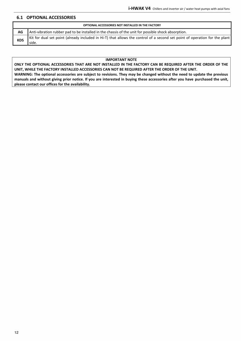
6.1 OPTIONAL ACCESSORIES OPTIONAL ACCESSORIES NOT INSTALLED IN THE FACTORY
AG Anti-vibration rubber pad to be installed in the chassis of the unit for possible shock absorption.
KDS Kit for dual set point (already included in Hi-T) that allows the control of a second set point of operation for the plant side.
IMPORTANT NOTE ONLY THE OPTIONAL ACCESSORIES THAT ARE NOT INSTALLED IN THE FACTORY CAN BE REQUIRED AFTER THE ORDER OF THE UNIT, WHILE THE FACTORY INSTALLED ACCESSORIES CAN NOT BE REQUIRED AFTER THE ORDER OF THE UNIT. WARNING: The optional accessories are subject to revisions. They may be changed without the need to update the previous manuals and without giving prior notice. If you are interested in buying these accessories after you have purchased the unit, please contact our offices for the availability.
i-HWAK V4 Chillers and inverter air / water heat pumps with axial fans
13
7 INSTALLATION
WARNING: All the operation described in next chapters MUST BE DONE BY TRAINED PEOPLE ONLY. Before any operation on the unit, be sure that the electric supply is disconnected. Be sure also, using suitable obstructions, that can avoid accidental power supply switching ON until the end of all operations.
7.1 GENERALITY When installing or servicing the unit, it is necessary to strictly follow the rules listed in this manual, to conform to all the specifications of the labels on the unit, and to take any possible precautions. Not observing the rules reported on this manual can create dangerous situations.
After receiving the unit, immediately check its integrity. The unit left the factory in perfect condition; any eventual damage has to be questioned to the carrier and recorded on the Delivery Note before signing it.
The company has to be informed, within 8 days, of the extent of the damage. The Customer should prepare a written statement of any severe damage.
WARNING: The units are designed for outdoor installation. The place of installation must be entirely far away from fire risk. All the necessary measures should be adopted in order to prevent the fire risk in the place of installation. The outdoor ambient temperature shall not exceed 46°C. Above this value, the unit is no longer covered by the directives in force in the area of pressure equipment.
WARNING: The unit should be installed so that adequate clearance is available for maintenance and repairation. The warranty does not cover costs related to platforms or handling equipment necessary for any maintenance.
All maintenance and testing operations should be carried out only by QUALIFIED PERSONNEL.
Before any operation on the unit, make sure the power supply is disconnected.
WARNING: MOVING PARTS, RISK OF DEATH. Disconnect the power supply and ensure that the fan is stopped before opening the front panel.
The temperatures of heads and discharge piping of the compressor are usually high.
Be careful when working near condensing coils. The aluminum fins are very sharp and can cause serious injuries.
After the maintenance operations, close the panels tightly with the fastening screws.
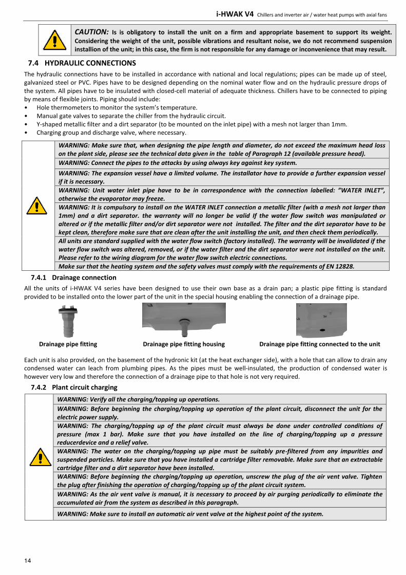
7.2 LIFTING AND HANDLING
When unloading and installing the unit, it is highly recommended to avoid any sudden move in order to protect the inner components. Units can be lifted by means of a forklift or, in alternative, of belts, being sure not to damage the lateral panels and the cover. It is important to keep the unit horizontal during these operations.
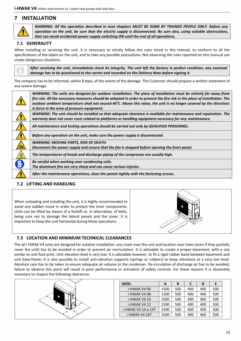
7.3 LOCATION AND MINIMUM TECHNICAL CLEARANCES
The all i-HWAK V4 units are designed for outdoor installation: any cover over the unit and location near trees (even if they partially cover the unit) has to be avoided in order to prevent air recirculation. It is advisable to create a proper basement, with a size similar to unit foot-print. Unit vibration level is very low: it is advisable however, to fit a rigid rubber band between basement and unit base-frame. It is also possible to install anti-vibration supports (springs or rubbers) to keep vibrations at a very low level. Absolute care has to be taken to ensure adequate air volume to the condenser. Re-circulation of discharge air has to be avoided; failure to observe this point will result in poor performance or activation of safety controls. For these reasons it is absolutely necessary to respect the following clearances:
MOD. A B C D E i-HWAK V4 06 1500 500 400 400 500 i-HWAK V4 08 1500 500 400 400 500 i-HWAK V4 10 1500 500 400 400 500 i-HWAK V4 12 1500 500 400 400 500
i-HWAK V4 14 e 14T 1500 500 400 400 500 i-HWAK V4 16T 1500 500 400 400 500
i-HWAK V4 Chillers and inverter air / water heat pumps with axial fans
14
CAUTION: Is is obligatory to install the unit on a firm and appropriate basement to support its weight. Considering the weight of the unit, possible vibrations and resultant noise, we do not recommend suspension installion of the unit; in this case, the firm is not responsible for any damage or inconvenience that may result.
7.4 HYDRAULIC CONNECTIONS The hydraulic connections have to be installed in accordance with national and local regulations; pipes can be made up of steel, galvanized steel or PVC. Pipes have to be designed depending on the nominal water flow and on the hydraulic pressure drops of the system. All pipes have to be insulated with closed-cell material of adequate thickness. Chillers have to be connected to piping by means of flexible joints. Piping should include: • Hole thermometers to monitor the system’s temperature. • Manual gate valves to separate the chiller from the hydraulic circuit. • Y-shaped metallic filter and a dirt separator (to be mounted on the inlet pipe) with a mesh not larger than 1mm. • Charging group and discharge valve, where necessary.
WARNING: Make sure that, when designing the pipe length and diameter, do not exceed the maximum head loss on the plant side, please see the technical data given in the table of Paragraph 12 (available pressure head). WARNING: Connect the pipes to the attacks by using always key against key system. WARNING: The expansion vessel have a limited volume. The installator have to provide a further expansion vessel if it is necessary. WARNING: Unit water inlet pipe have to be in correspondence with the connection labelled: ”WATER INLET”, otherwise the evaporator may freeze. WARNING: It is compulsory to install on the WATER INLET connection a metallic filter (with a mesh not larger than 1mm) and a dirt separator. the warranty will no longer be valid If the water flow switch was manipulated or altered or if the metallic filter and/or dirt separator were not installed. The filter and the dirt separator have to be kept clean, therefore make sure that are clean after the unit installing the unit, and then check them periodically. All units are standard supplied with the water flow switch (factory installed). The warranty will be invalidated if the water flow switch was altered, removed, or if the water filter and the dirt separator were not installed on the unit. Please refer to the wiring diagram for the water flow switch electric connections. Make sur that the heating system and the safety valves must comply with the requirements of EN 12828.
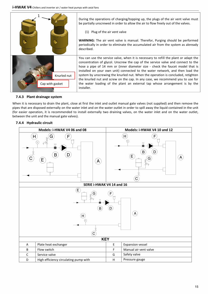
7.4.1 Drainage connection All the units of i-HWAK V4 series have been designed to use their own base as a drain pan; a plastic pipe fitting is standard provided to be installed onto the lower part of the unit in the special housing enabling the connection of a drainage pipe.
Each unit is also provided, on the basement of the hydronic kit (at the heat exchanger side), with a hole that can allow to drain any condensed water can leach from plumbing pipes. As the pipes must be well-insulated, the production of condensed water is however very low and therefore the connection of a drainage pipe to that hole is not very required.
7.4.2 Plant circuit charging
WARNING: Verify all the charging/topping up operations. WARNING: Before beginning the charging/topping up operation of the plant circuit, disconnect the unit for the electric power supply. WARNING: The charging/topping up of the plant circuit must always be done under controlled conditions of pressure (max 1 bar). Make sure that you have installed on the line of charging/topping up a pressure reducerdevice and a relief valve. WARNING: The water on the charging/topping up pipe must be suitably pre-filtered from any impurities and suspended particles. Make sure that you have installed a cartridge filter removable. Make sure that an extractable cartridge filter and a dirt separator have been installed. WARNING: Before beginning the charging/topping up operation, unscrew the plug of the air vent valve. Tighten the plug after finishing the operation of charging/topping up of the plant circuit system. WARNING: As the air vent valve is manual, it is necessary to proceed by air purging periodically to eliminate the accumulated air from the system as described in this paragraph.
WARNING: Make sure to install an automatic air vent valve at the highest point of the system.
Drainage pipe fitting Drainage pipe fitting housing Drainage pipe fitting connected to the unit
i-HWAK V4 Chillers and inverter air / water heat pumps with axial fans
15
7.4.3 Plant drainage system
When it is necessary to drain the plant, close at first the inlet and outlet manual gate valves (not supplied) and then remove the pipes that are disposed externally on the water inlet and on the water outlet in order to spill away the liquid contained in the unit (for easier operation, it is recommended to install externally two draining valves, on the water inlet and on the water outlet, between the unit and the manual gate valves).
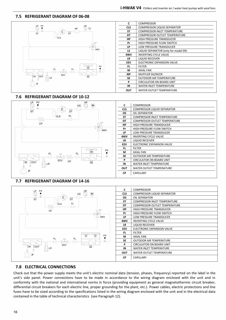
7.4.4 Hydraulic circuit
Models: i-HWAK V4 06 and 08 Models: i-HWAK V4 10 and 12
AB
H FG
ED
C
i-HWAK 06/08 V4
AB
H F
GED
C
i-HWAK 10/12 V4
SERIE i-HWAK V4 14 and 16
AB
H
FGE
D
C
i-HWAK 14/16 V4
KEY
A Plate heat exchanger E Expansion vessel B Flow switch F Manual air vent valve C Service valve G Safety valve D High efficiency circulating pump with H Pressure gauge
During the operations of charging/topping up, the plugs of the air vent valve must be partially unscrewed in order to allow the air to flow freely out of the valves.
(1) Plug of the air vent valve
WARNING: The air vent valve is manual. Therefor, Purging should be performed periodically in order to eliminate the accumulated air from the system as aleready described.
You can use the service valve, when it is necessary to refill the plant or adapt the concentration of glycol. Unscrew the cap of the service valve and connect to the hose a pipe of 14 mm or (inner diameter size - check the faucet model that is installed on your own unit) connected to the water network, and then load the system by unscrewing the knurled nut. When the operation is concluded, retighten the knurled nut and screw on the cap. In any case, we recommend you to use for the water loading of the plant an external tap whose arrangement is by the installer.
Cap with gasket
Knurled nut
1
i-HWAK V4 Chillers and inverter air / water heat pumps with axial fans
16
7.5 REFRIGERANT DIAGRAM OF 06-08
IN OUT
DTST
LP HP
4WV
LREEV
FL FL
C
CLS
PrPV
PV
MF
SE
M
P
C COMPRESSOR CLS COMPRESSOR LIQUID SEPARATOR ST COMPRESSOR INLET TEMPERATURE DT COMPRESSOR OUTLET TEMPERATURE HP HIGH PRESSURE TRANSDUCER Pr HIGH PRESSURE FLOW SWITCH LP LOW PRESSURE TRANSDUCER LS LIQUID SEPARATOR (only for model 09)
4WV INVERTING CYCLE VALVE LR LIQUID RECEIVER
EEV ELECTRONIC EXPANSION VALVE FL FILTER M AXIAL FAN
MF MUFFLER SILENCER SE OUTDOOR AIR TEMPERATURE P CIRCULATOR ON BOARD UNIT IN WATER INLET TEMPERATURE
OUT WATER OUTLET TEMPERATURE
7.6 REFRIGERANT DIAGRAM OF 10-12
IN OUT
DT
OS
i-HWAK 10 / 12 V4
ST
LP HP
4WV
LREEV
FL FL
FL
C
CLS
PrPrPV
PV
CP
CP SE
M
P
C COMPRESSOR CLS COMPRESSOR LIQUID SEPARATOR OS OIL SEPARATOR ST COMPRESSOR INLET TEMPERATURE DT COMPRESSOR OUTLET TEMPERATURE HP HIGH PRESSURE TRANSDUCER Pr HIGH PRESSURE FLOW SWITCH LP LOW PRESSURE TRANSDUCER
4WV INVERTING CYCLE VALVE LR LIQUID RECEIVER
EEV ELECTRONIC EXPANSION VALVE FL FILTER M AXIAL FAN SE OUTDOOR AIR TEMPERATURE P CIRCULATOR ON BOARD UNIT IN WATER INLET TEMPERATURE
OUT WATER OUTLET TEMPERATURE CP CAPILLARY
7.7 REFRIGERANT DIAGRAM OF 14-16
IN OUT
DT
OS
ST
LP HP
4WV
LREEV
FL FL
FL
C
CLS
PrPV
Pr
PV
CP
SE
MM
P
C COMPRESSOR CLS COMPRESSOR LIQUID SEPARATOR OS OIL SEPARATOR ST COMPRESSOR INLET TEMPERATURE DT COMPRESSOR OUTLET TEMPERATURE HP HIGH PRESSURE TRANSDUCER Pr HIGH PRESSURE FLOW SWITCH LP LOW PRESSURE TRANSDUCER
4WV INVERTING CYCLE VALVE LR LIQUID RECEIVER
EEV ELECTRONIC EXPANSION VALVE FL FILTER M AXIAL FAN SE OUTDOOR AIR TEMPERATURE P CIRCULATOR ON BOARD UNIT IN WATER INLET TEMPERATURE
OUT WATER OUTLET TEMPERATURE
CP CAPILLARY
7.8 ELECTRICAL CONNECTIONS Check out that the power supply meets the unit’s electric nominal data (tension, phases, frequency) reported on the label in the unit’s side panel. Power connections have to be made in accordance to the wiring diagram enclosed with the unit and in conformity with the national and international norms in force (providing equipment as general magnetothermic circuit breaker, differential circuit breakers for each electric line, proper grounding for the plant, etc.). Power cables, electric protections and line fuses have to be sized according to the specifications listed in the wiring diagram enclosed with the unit and in the electrical data contained in the table of technical characteristics (see Paragraph 12).
i-HWAK V4 Chillers and inverter air / water heat pumps with axial fans
17
WARNING: The electrical panel is located under the coping plate. It is necessary to respect the minimum clearances given in section 7.3 in order to be able to connect the wires.
WARNING: Installer has to provide a general circuit breaker (for example a magnetothermic circuit breaker) at the beginning of unit circuit system.
WARNING: The supply voltage’s fluctuations cannot exceed ±10% of the nominal value. Should this tolerance not be respected, please contact our technical department.
WARNING: The power supply have to respect the listed limits: failing this, warranty will terminate immediately. Before any operation on the unit, be sure that the power supply is disconnected. WARNING: The water flow switch (B component in the previous hydraulic circuit and factory installed) have ALWAYS to be connected following the indications listed in the wiring diagram. Never bridge the water flow switch connections in the terminal board. Should the water flow switch connections altered or not properly made, the guarantee will be invalidated.
WARNING: The remote control panel is connected to the water chiller by means of no.4 wires having a 1,5 mm2 section. The power supply cables have to be separated from the remote control wires. The maximum distance is 50m.
WARNING: The remote control panel cannot be installed in areas with strong vibrations, corrosive gases, and excess of dirtiness or high humidity levels. Leave free the area near the cooling openings.
7.8.1 Wiring terminal block
Electrical wiring have to be done only by qualified personnel.
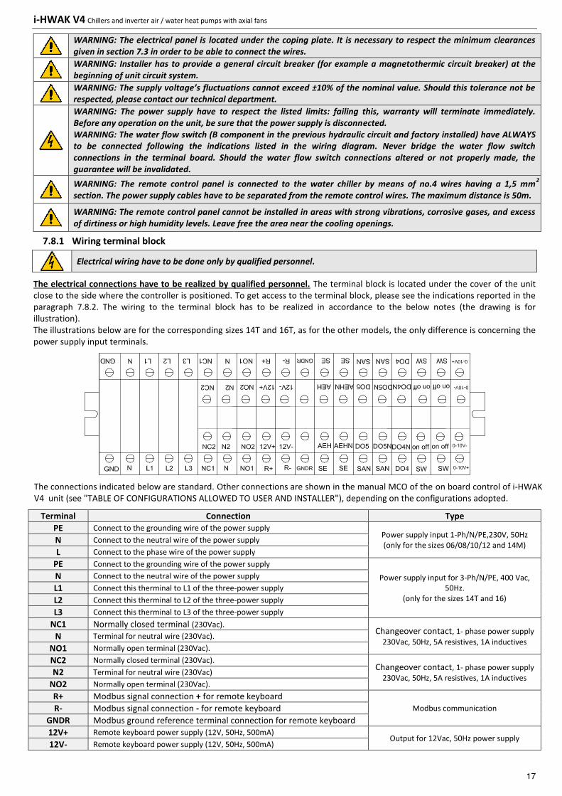
The electrical connections have to be realized by qualified personnel. The terminal block is located under the cover of the unit close to the side where the controller is positioned. To get access to the terminal block, please see the indications reported in the paragraph 7.8.2. The wiring to the terminal block has to be realized in accordance to the below notes (the drawing is for illustration). The illustrations below are for the corresponding sizes 14T and 16T, as for the other models, the only difference is concerning the power supply input terminals.
The connections indicated below are standard. Other connections are shown in the manual MCO of the on board control of i-HWAK V4 unit (see "TABLE OF CONFIGURATIONS ALLOWED TO USER AND INSTALLER"), depending on the configurations adopted.
Terminal Connection Type PE Connect to the grounding wire of the power supply
Power supply input 1-Ph/N/PE,230V, 50Hz (only for the sizes 06/08/10/12 and 14M) N Connect to the neutral wire of the power supply
L Connect to the phase wire of the power supply PE Connect to the grounding wire of the power supply
Power supply input for 3-Ph/N/PE, 400 Vac, 50Hz.
(only for the sizes 14T and 16)
N Connect to the neutral wire of the power supply L1 Connect this therminal to L1 of the three-power supply L2 Connect this therminal to L2 of the three-power supply L3 Connect this therminal to L3 of the three-power supply
NC1 Normally closed terminal (230Vac). Changeover contact, 1- phase power supply
230Vac, 50Hz, 5A resistives, 1A inductives N Terminal for neutral wire (230Vac).
NO1 Normally open terminal (230Vac). NC2 Normally closed terminal (230Vac).
Changeover contact, 1- phase power supply 230Vac, 50Hz, 5A resistives, 1A inductives
N2 Terminal for neutral wire (230Vac) NO2 Normally open terminal (230Vac). R+ Modbus signal connection + for remote keyboard
Modbus communication R- Modbus signal connection - for remote keyboard GNDR Modbus ground reference terminal connection for remote keyboard 12V+ Remote keyboard power supply (12V, 50Hz, 500mA)
Output for 12Vac, 50Hz power supply 12V- Remote keyboard power supply (12V, 50Hz, 500mA)
i-HWAK V4 Chillers and inverter air / water heat pumps with axial fans
18
SE/SE Programmable analog input with sensor NTC-10kΏ at 25°C β 3435. Or voltage-free digital input Analog or digital input
AEHN Terminal for neutral line of (230Vac) Under-voltage output single phase 230Vac, 50Hz, 5A resistive, 1A inductive. AEH Terminal of phase line of (230Vac).
SAN/SAN Programmable analog input with sensor NTC-10kΏ at 25°C β 3435. Or voltage-free digital input Analog or digital input
DO4N Terminal for neutral line of single phase power supply (230Vac). Under-voltage output single phase 230Vac, 50Hz, 5A resistive, 1A inductive.
Can be used in the versions without KA DO4 Terminal for phase line of (230Vac).
DO5N Terminal for neutral line of (230Vac). Under-voltage output single phase 230Vac, 50Hz, 5A resistive, 1A inductive.
Can be used in the versions without KA DO5 Terminal for phase line of (230Vac).
SW/SW Input for summer/winter mode commutation from remote control panel (to activate this function, please see corresponding paragraph in the control manual MCO)
Voltage-free digital input
onoff /onoff on/off remote input (closed = unit is ON / open =uniti s OFF) Voltage-free digital input
0-10V+ Signal input: 0-10V (+) for set point adjustment Analog input (ST10)
0-10V- Signal input: 0-10V (-) for set point adjustment
7.8.2 Terminal block and the electric box
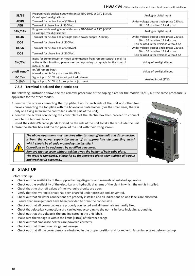
The following illustration shows the the removal procedure of the coping plate for the models 14/16, but the same procedure is applicable for the other models
1. Remove the screws connecting the top plate. Two for each side of the unit and other two crews connecting the top plate with the hole-cable plate holder. (For the small sizes, there is only one fixing screw in the controller’s lateral part of the unit)
2. Remove the screws connecting the cover plate of the electric box then proceed to connect wire to the terminal block.
3. Insert the cables PG cable glands located on the side of the unit to take them outside the unit 4. Close the electric box and the top panel of the unit with their fixing screws.
The above operations must be done after turning off the unit and disconnecting it from the power supply (by mean of an appropriate disconnecting switch which should be already mouted by the installer). Operations to be performed by qualified personnel. Remove the top cover without taking away the holder of hole-cabe plate. The work is completed, please fix all the removed plates then tighten all screws and washers (if expected).
8 START UP Before start-up: x Check out the availability of the supplied wiring diagrams and manuals of installed apparatus. x Check out the availability of the electrical and hydraulic diagrams of the plant in which the unit is installed. x Check that the shut-off valves of the hydraulic circuits are open. x Verify that the hydraulic circuit has been charged under pressure and air vented. x Check out that all water connections are properly installed and all indications on unit labels are observed. x Ensure that arrangements have been provided to drain the condensate. x Check out that all power cables are properly connected and all terminals are hardly fixed. x Check that electrical connections are carried out according to the norms in force including grounding. x Check out that the voltage is the one indicated in the unit labels. x Make sure the voltage is within the limits (±10%) of tolerance range. x Check out that crankcase heaters are powered correctly. x Check out that there is no refrigerant leakage. x Check out that all the cover panels are installed in the proper position and locked with fastening screws before start up.
i-HWAK V4 Chillers and inverter air / water heat pumps with axial fans
19
WARNING: The unit must be connected to the electrical network and should be in STAND-BY mode (powered) closing the general switch in order to operate the crankcase heaters of the compressor for a minimum of 12 hours before start up. (the heaters are automatically powered when the main switch is switched off). The crankcase heaters are working properly if, after some minutes, the temperature of crankcase’s compressor is about 10°C ÷ 15°C higher than ambient temperature. WARNING: The weight of the pipes doesn’t load unit structure. WARNING: Never switch off the unit (for a temporary stop) by switching off the main switch: this component should be used to disconnect the unit from the power supply only for lengthy stoppages (e.g. seasonal stoppages). Besides, failing the power supply, the crankcase’s heaters are not supplied thus resulting in a possible breakdown of the compressors once the unit is switched on. WARNING: Do not modify the internal wiring of the unit otherwise the warranty will terminate immediately. WARNING: The summer/winter operating mode have to be selected at the beginning of the related season. Frequent and sudden changes of this seasonal operating mode have to be avoided in order to prevent severe damages to compressors. WARNING: When you first install and start-up the unit make sure that the unit is working properly in both cooling and heating modes.
9 SHUTDOWNS FOR LONG PERIODS The types of shutdown depends on the weather of the site where the unit is installed and on the period of the stop. The antifreeze system, if it’s installed, stay on work also with the on-board control unit in “OFF” position. If the time of stop is long and the temperature is low, we recommend to drain the hydraulic circuits or use a mixture of water and glycol. Drain the hydraulic circuits and shutdown the unit with this passage: x Turn off the unit by placing the switch of each unit to "OFF" position. x Close the water valves. x Place the general differential circuit breaker on "OFF" position, if it is installed upstream of the system.
If the temperature drops below 0°C there is serious danger of frost: add a mixture of water and glycol in the plant, otherwise drain the hydraulic circuits of the plant and of the heat pump.
WARNING: the operation, although it was transient, with water temperatures below +5°C is not guaranteed on the basis of the limits set out in Paragraph 15.4. Before you turn the unit on after a long off period, make sure that the temperature of the mixture of water and glycol is higher than or at least equal to + 5°C.
10 MAINTENANCE AND PERIODICAL CONTROLS
WARNING: All the operations described in this chapter HAVE TO BE CARRIED OUT BY TRAINED STAFF ONLY. Before any operation or before entering the inner components of the unit, be sure that the power supply is disconnected. The compressor’s heads and discharge piping are usually at high temperature levels. Be very careful when operating in their surroundings. Aluminium coil fins are very sharp and can cause serious wounds. Be very careful when operating in their surroundings. After maintenance operations, re-install the cover panels, and fix them by means of screws.
The refrigerant circuits must not be filled with different gas other than that indicated on the nameplate. The use of a different refrigerant can cause severe damage to the compressor.
It’s forbidden to use oils other than those specified in this manual. The use of a different oil can cause serious damage to the compressor.
The temperatures of heads and discharge piping of the compressor are usually high.
Be careful when working near condensing coils. The aluminum fins are very sharp and can cause serious injuries.
After the maintenance operations, close the panels tightly with the fastening screws.
Be sure that only trained and qualified personnel to perform maintenance operation and periodical inspections on the equipment. The EU Regulation 517/2014 establishes that users should assign a qualified personnel to be responsible to regularly carry out inspections of the facilities, to perform tightness test and elimating eventual leakages within the shortest possible time. Also has to check the obligatoriness and the necessary documentation about the Regulation (EU) No 517/2014 and its subsequent amendment or repeal.
i-HWAK V4 Chillers and inverter air / water heat pumps with axial fans
20
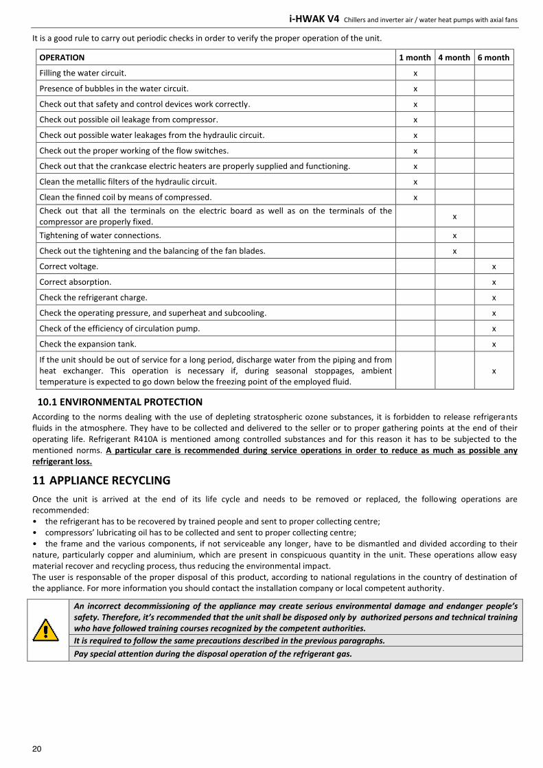
It is a good rule to carry out periodic checks in order to verify the proper operation of the unit.
OPERATION 1 month 4 month 6 month
Filling the water circuit. x
Presence of bubbles in the water circuit. x
Check out that safety and control devices work correctly. x
Check out possible oil leakage from compressor. x
Check out possible water leakages from the hydraulic circuit. x
Check out the proper working of the flow switches. x
Check out that the crankcase electric heaters are properly supplied and functioning. x
Clean the metallic filters of the hydraulic circuit. x
Clean the finned coil by means of compressed. x Check out that all the terminals on the electric board as well as on the terminals of the compressor are properly fixed. x
Tightening of water connections. x
Check out the tightening and the balancing of the fan blades. x
Correct voltage. x
Correct absorption. x
Check the refrigerant charge. x
Check the operating pressure, and superheat and subcooling. x
Check of the efficiency of circulation pump. x
Check the expansion tank. x
If the unit should be out of service for a long period, discharge water from the piping and from heat exchanger. This operation is necessary if, during seasonal stoppages, ambient temperature is expected to go down below the freezing point of the employed fluid.
x
10.1 ENVIRONMENTAL PROTECTION According to the norms dealing with the use of depleting stratospheric ozone substances, it is forbidden to release refrigerants fluids in the atmosphere. They have to be collected and delivered to the seller or to proper gathering points at the end of their operating life. Refrigerant R410A is mentioned among controlled substances and for this reason it has to be subjected to the mentioned norms. A particular care is recommended during service operations in order to reduce as much as possible any refrigerant loss.
11 APPLIANCE RECYCLING Once the unit is arrived at the end of its life cycle and needs to be removed or replaced, the following operations are recommended: • the refrigerant has to be recovered by trained people and sent to proper collecting centre; • compressors’ lubricating oil has to be collected and sent to proper collecting centre; • the frame and the various components, if not serviceable any longer, have to be dismantled and divided according to their nature, particularly copper and aluminium, which are present in conspicuous quantity in the unit. These operations allow easy material recover and recycling process, thus reducing the environmental impact. The user is responsable of the proper disposal of this product, according to national regulations in the country of destination of the appliance. For more information you should contact the installation company or local competent authority.
An incorrect decommissioning of the appliance may create serious environmental damage and endanger people’s safety. Therefore, it’s recommended that the unit shall be disposed only by authorized persons and technical training who have followed training courses recognized by the competent authorities. It is required to follow the same precautions described in the previous paragraphs. Pay special attention during the disposal operation of the refrigerant gas.
i-HWAK V4 Chillers and inverter air / water heat pumps with axial fans
21
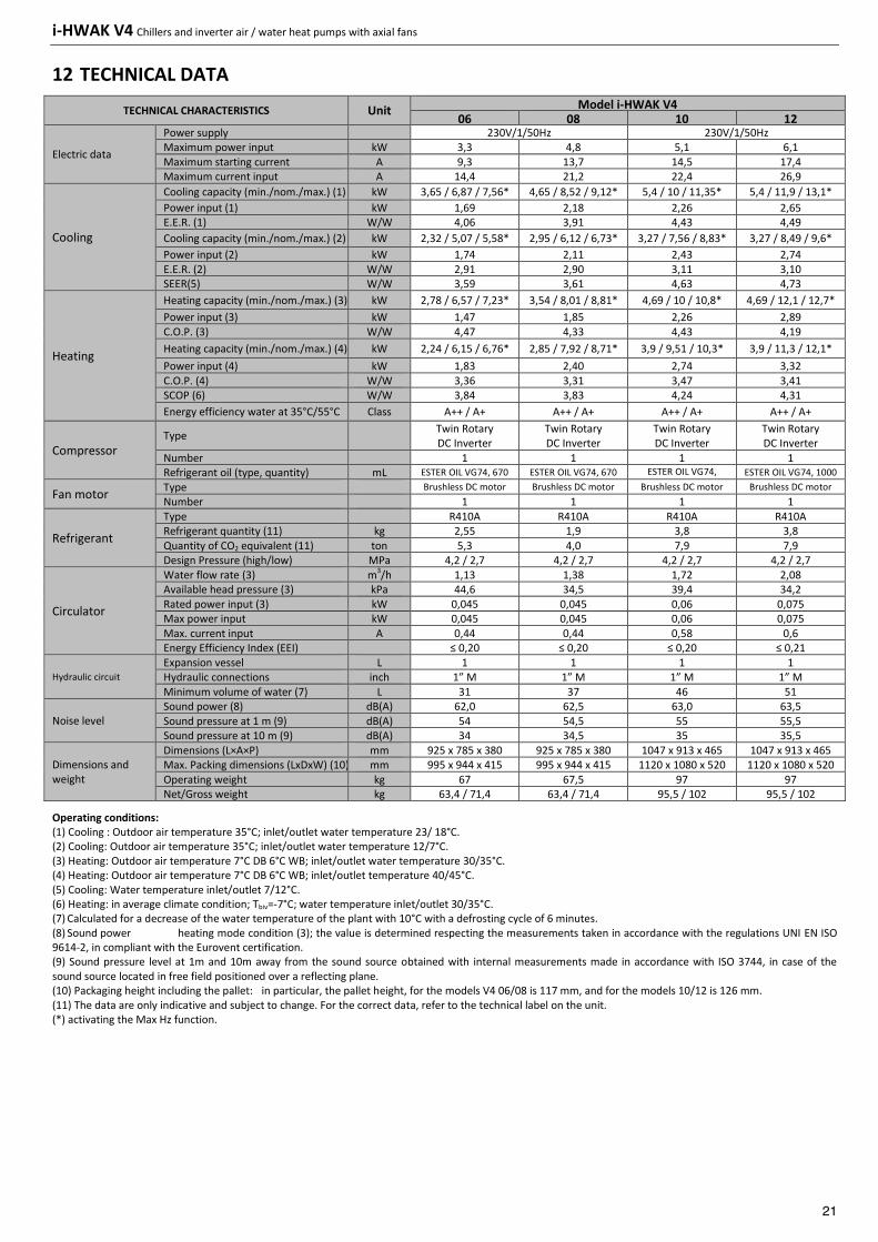
12 TECHNICAL DATA
TECHNICAL CHARACTERISTICS Unit Model i-HWAK V4 06 08 10 12
Electric data
Power supply 230V/1/50Hz 230V/1/50Hz Maximum power input kW 3,3 4,8 5,1 6,1 Maximum starting current A 9,3 13,7 14,5 17,4 Maximum current input A 14,4 21,2 22,4 26,9
Cooling
Cooling capacity (min./nom./max.) (1) kW 3,65 / 6,87 / 7,56* 4,65 / 8,52 / 9,12* 5,4 / 10 / 11,35* 5,4 / 11,9 / 13,1* Power input (1) kW 1,69 2,18 2,26 2,65 E.E.R. (1) W/W 4,06 3,91 4,43 4,49 Cooling capacity (min./nom./max.) (2) kW 2,32 / 5,07 / 5,58* 2,95 / 6,12 / 6,73* 3,27 / 7,56 / 8,83* 3,27 / 8,49 / 9,6* Power input (2) kW 1,74 2,11 2,43 2,74 E.E.R. (2) W/W 2,91 2,90 3,11 3,10 SEER(5) W/W 3,59 3,61 4,63 4,73
Heating
Heating capacity (min./nom./max.) (3) kW 2,78 / 6,57 / 7,23* 3,54 / 8,01 / 8,81* 4,69 / 10 / 10,8* 4,69 / 12,1 / 12,7* Power input (3) kW 1,47 1,85 2,26 2,89 C.O.P. (3) W/W 4,47 4,33 4,43 4,19 Heating capacity (min./nom./max.) (4) kW 2,24 / 6,15 / 6,76* 2,85 / 7,92 / 8,71* 3,9 / 9,51 / 10,3* 3,9 / 11,3 / 12,1* Power input (4) kW 1,83 2,40 2,74 3,32 C.O.P. (4) W/W 3,36 3,31 3,47 3,41 SCOP (6) W/W 3,84 3,83 4,24 4,31 Energy efficiency water at 35°C/55°C Class A++ / A+ A++ / A+ A++ / A+ A++ / A+
Compressor Type Twin Rotary
DC Inverter Twin Rotary DC Inverter
Twin Rotary DC Inverter
Twin Rotary DC Inverter
Number 1 1 1 1 Refrigerant oil (type, quantity) mL ESTER OIL VG74, 670 ESTER OIL VG74, 670 ESTER OIL VG74,
1000 ESTER OIL VG74, 1000
Fan motor Type Brushless DC motor Brushless DC motor Brushless DC motor Brushless DC motor Number 1 1 1 1
Refrigerant
Type R410A R410A R410A R410A Refrigerant quantity (11) kg 2,55 1,9 3,8 3,8 Quantity of CO2 equivalent (11) ton 5,3 4,0 7,9 7,9 Design Pressure (high/low) MPa 4,2 / 2,7 4,2 / 2,7 4,2 / 2,7 4,2 / 2,7
Circulator
Water flow rate (3) m3/h 1,13 1,38 1,72 2,08 Available head pressure (3) kPa 44,6 34,5 39,4 34,2 Rated power input (3) kW 0,045 0,045 0,06 0,075 Max power input kW 0,045 0,045 0,06 0,075 Max. current input A 0,44 0,44 0,58 0,6 Energy Efficiency Index (EEI) circolatore
≤ 0,20 ≤ 0,20 ≤ 0,20 ≤ 0,21
Hydraulic circuit Expansion vessel L 1 1 1 1 Hydraulic connections inch 1” M 1” M 1” M 1” M Minimum volume of water (7) L 31 37 46 51
Noise level Sound power (8) dB(A) 62,0 62,5 63,0 63,5 Sound pressure at 1 m (9) dB(A) 54 54,5 55 55,5 Sound pressure at 10 m (9) dB(A) 34 34,5 35 35,5
Dimensions and weight
Dimensions (L×A×P) mm 925 x 785 x 380 925 x 785 x 380 1047 x 913 x 465 1047 x 913 x 465 Max. Packing dimensions (LxDxW) (10) mm 995 x 944 x 415 995 x 944 x 415 1120 x 1080 x 520 1120 x 1080 x 520 Operating weight kg 67 67,5 97 97 Net/Gross weight kg 63,4 / 71,4 63,4 / 71,4 95,5 / 102 95,5 / 102
Operating conditions: (1) Cooling : Outdoor air temperature 35°C; inlet/outlet water temperature 23/ 18°C. (2) Cooling: Outdoor air temperature 35°C; inlet/outlet water temperature 12/7°C. (3) Heating: Outdoor air temperature 7°C DB 6°C WB; inlet/outlet water temperature 30/35°C. (4) Heating: Outdoor air temperature 7°C DB 6°C WB; inlet/outlet temperature 40/45°C. (5) Cooling: Water temperature inlet/outlet 7/12°C. (6) Heating: in average climate condition; Tbiv=-7°C; water temperature inlet/outlet 30/35°C. (7) Calculated for a decrease of the water temperature of the plant with 10°C with a defrosting cycle of 6 minutes. (8) Sound power heating mode condition (3); the value is determined respecting the measurements taken in accordance with the regulations UNI EN ISO 9614-2, in compliant with the Eurovent certification. (9) Sound pressure level at 1m and 10m away from the sound source obtained with internal measurements made in accordance with ISO 3744, in case of the sound source located in free field positioned over a reflecting plane. (10) Packaging height including the pallet: in particular, the pallet height, for the models V4 06/08 is 117 mm, and for the models 10/12 is 126 mm. (11) The data are only indicative and subject to change. For the correct data, refer to the technical label on the unit. (*) activating the Max Hz function.
i-HWAK V4 Chillers and inverter air / water heat pumps with axial fans
22
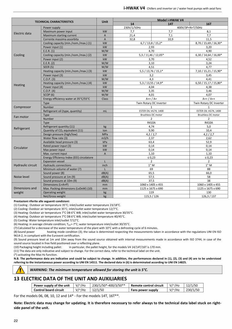
TECHNICAL CHARACTERISTICS Unit Model i-HWAK V4 14 14T 16T
Electric data
Power supply 230V/1/50Hz 400V/3P+N+T/50Hz Maximum power input kW 7,7 7,7 8,1 Maximum starting current A 21,4 7,1 7,7 Corrente massima assorbita A 32,8 10,9 11,5
Cooling
Cooling capacity (min./nom./max.) (1) kW 6,7 / 13,8 / 15,2* 8,70 / 15,69 / 16,30* Power input (1) kW 2,93 3,20 E.E.R. (1) W/W 4,70 4,90 Cooling capacity (min./nom./max.) (2) kW 5,3 / 11,46 / 12,05* 6,30 / 14,64 / 16,00* Power input (2) kW 3,70 4,52 E.E.R. (2) W/W 3,10 3,24 SEER (5) W/W 4,51 4,77
Heating
Heating capacity (min./nom./max.) (3) kW 5,5 / 13,76 / 15,1* 7,10 / 15,21 / 15,90* Power input (3) kW 3,2 3,45 C.O.P. (3) W/W 4,3 4,41 Heating capacity (min./nom./max.) (4) kW 5,3 / 13,55 / 14,9* 6,50 / 15,17 / 15,80* Power input (4) kW 4,04 4,38 C.O.P. (4) W/W 3,35 3,46 SCOP (6) W/W 4,01 4,07 Energy efficiency water at 35°C/55°C Class A++ / A+ A++ / A++
Compressor Type Twin Rotary DC Inverter Twin Rotary DC Inverter Number 1 1 Refrigerant oil (type, quantity) mL ESTER OIL VG74, 1400 ESTER OIL VG74, 1400
Fan motor Type Brushless DC motor Brushless DC motor Number 2 2
Refrigerant
Type R410A R410A Refrigerant quantity (11) kg 4,74 5,0 Quantity of CO2 equivalent (11) ton 9,90 10,4 Design pressure (high/low) MPa 4,2 / 2,7 4,2 / 2,7
Circulator
Water flow rate (3) m3/h 2,37 2,62 Available head pressure (3) kPa 63,4 52,9 Rated power input (3) kW 0,14 0,14 Max power input kW 0,14 0,14 Max. current input A 1,10 1,10 Energy Efficiency Index (EEI) circolatore ≤ 0,23 ≤ 0,23
Hydraulic circuit Expansion vessel L 2 2 Hydraulic connections inch 1” M 1” M Minimum volume of water (7) L 69 88
Noise level Sound power (8) dB(A) 65,5 66,0 Sound pressure at 1m (9) dB(A) 57,5 58 Sound pressure at 10m (9) dB(A) 37,5 38
Dimensions and weight
Dimensions (L×A×P) mm 1060 x 1405 x 455 1060 x 1405 x 455 Max. Packing dimensions (LxDxW) (10) mm 1125 x 1675 x 690 1125 x 1675 x 690 Operating weight kg 119 130 Net/Gross weight kg 115,5 / 126 126,3 / 137
Prestazioni riferite alle seguenti condizioni: (1) Cooling : Outdoor air temperature 35°C; inlet/outlet water temperature 23/18°C. (2) Cooling: Outdoor air temperature 35°C; inlet/outlet water temperature 12/7°C. (3) Heating: Outdoor air temperature 7°C DB 6°C WB; inlet/outlet water temperature 30/35°C. (4) Heating: Outdoor air temperature 7°C DB 6°C WB; inlet/outlet temperature 40/45°C. (5) Cooling: Water temperature inlet/outlet 7/12°C. (6) Heating: in average climate condition; Tbiv=-7°C; water temperature inlet/outlet 30/35°C. (7) Calculated for a decrease of the water temperature of the plant with 10°C with a defrosting cycle of 6 minutes. (8) Sound power heating mode condition (3); the value is determined respecting the measurements taken in accordance with the regulations UNI EN ISO 9614-2, in compliant with the Eurovent certification. (9) Sound pressure level at 1m and 10m away from the sound source obtained with internal measurements made in accordance with ISO 3744, in case of the sound source located in free field positioned over a reflecting plane. (10) Packaging height including pallet: in particular, the pallet height, for the models V4 14/14T/16T is 170 mm. (11) The data are only indicative and subject to change. For the correct data, refer to the technical label on the unit. (*) activating the Max Hz function. N.B. The performance data are indicative and could be subject to change. In addition, the performances declared in (1), (2), (3) and (4) are to be understood referring to the instantaneous power according to UNI EN 14511. The declared data in (6) is determinated according to UNI EN 14825.
WARNING: The minimum temperature allowed for storing the unit is 5°C.
13 ELECTRIC DATA OF THE UNIT AND AUXILIARIES Power supply of the unit V/~/Hz 230/1/50*-400/3/50** Remote control circuit V/~/Hz 12/1/50 Control board circuit V/~/Hz 12/1/50 Fans power supply V/~/Hz 230/1/50
For the models 06, 08, 10, 12 and 14* - For the models 14T, 16T**.
Note: Electric data may change for updating. It is therefore necessary to refer always to the technical data label stuck on right-side panel of the unit.
i-HWAK V4 Chillers and inverter air / water heat pumps with axial fans
23
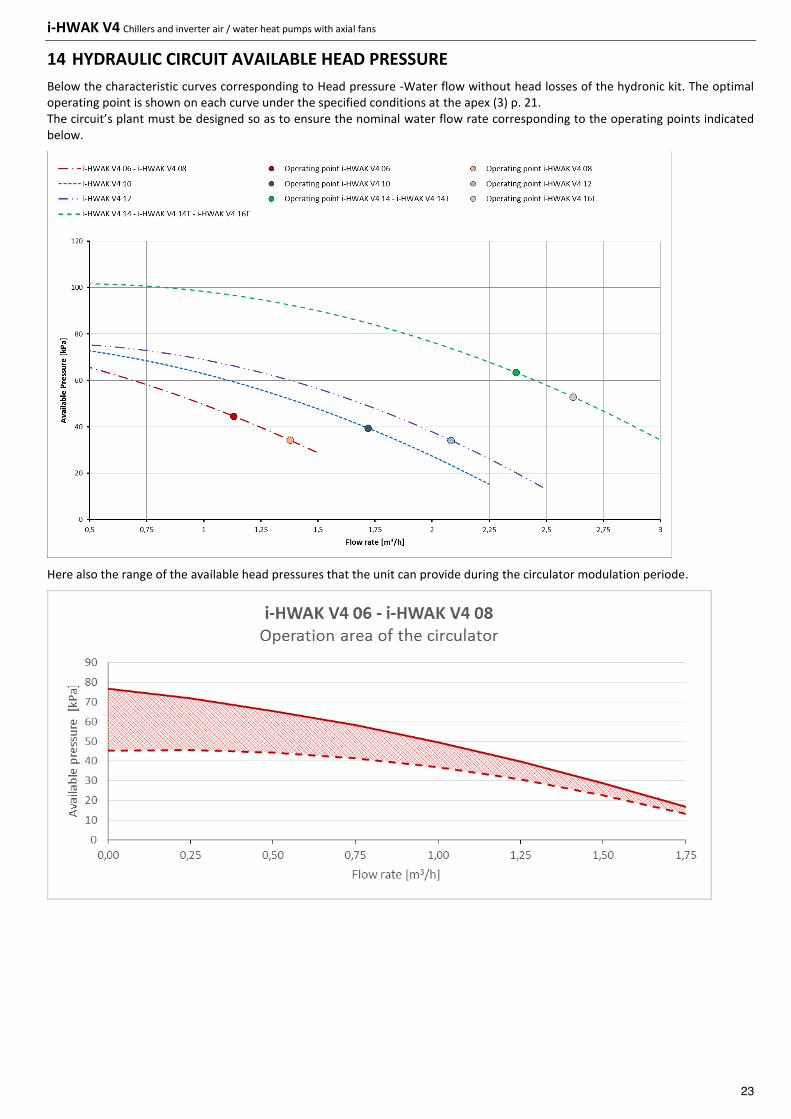
14 HYDRAULIC CIRCUIT AVAILABLE HEAD PRESSURE Below the characteristic curves corresponding to Head pressure -Water flow without head losses of the hydronic kit. The optimal operating point is shown on each curve under the specified conditions at the apex (3) p. 21. The circuit’s plant must be designed so as to ensure the nominal water flow rate corresponding to the operating points indicated below.
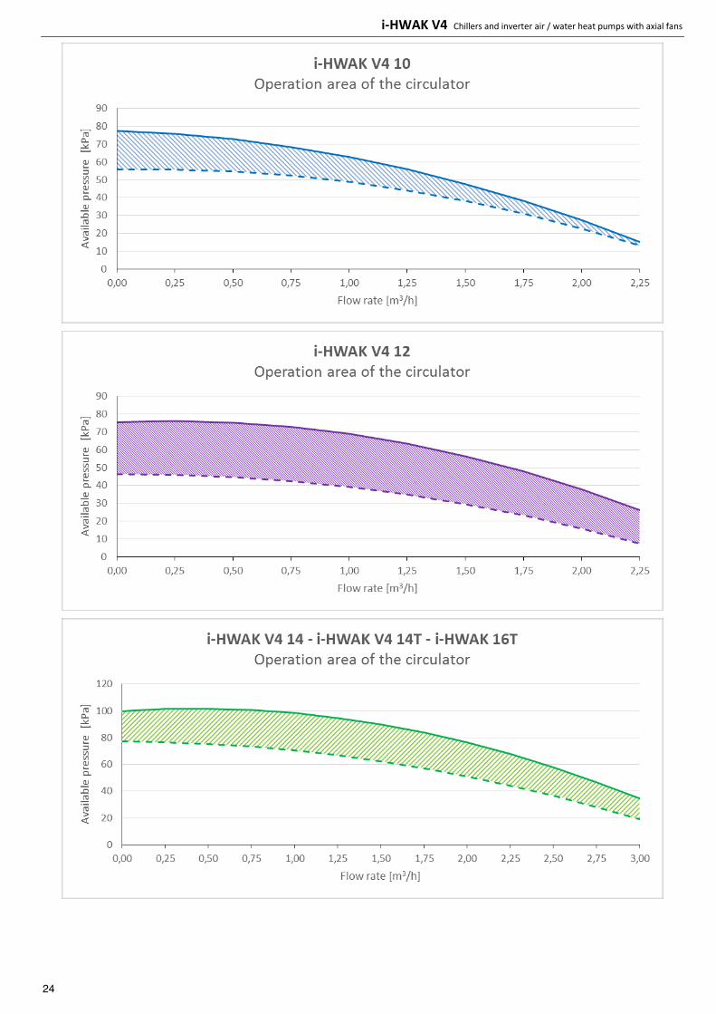
Here also the range of the available head pressures that the unit can provide during the circulator modulation periode.
i-HWAK V4 Chillers and inverter air / water heat pumps with axial fans
24
i-HWAK V4 Chillers and inverter air / water heat pumps with axial fans
25
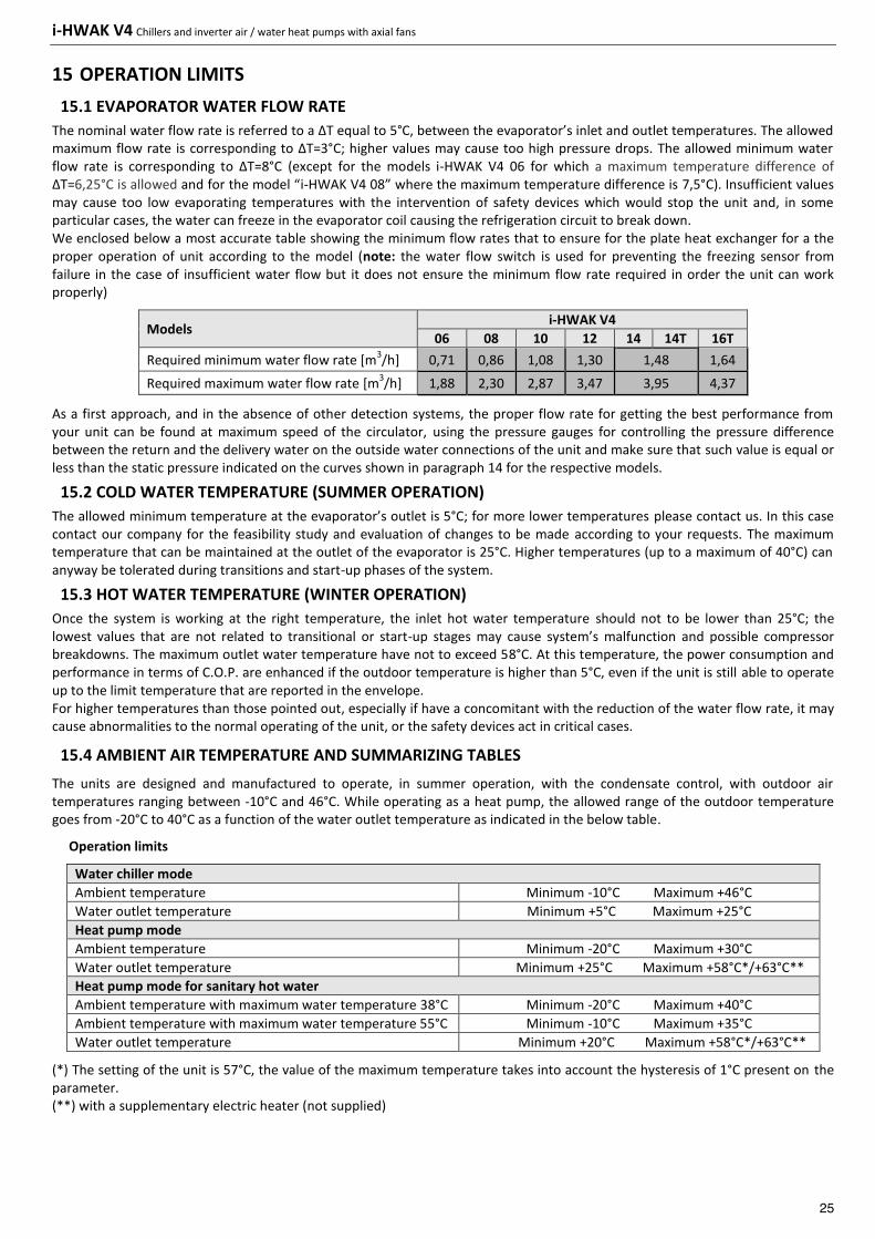
15 OPERATION LIMITS 15.1 EVAPORATOR WATER FLOW RATE
The nominal water flow rate is referred to a ∆T equal to 5°C, between the evaporator’s inlet and outlet temperatures. The allowed maximum flow rate is corresponding to ∆T=3°C; higher values may cause too high pressure drops. The allowed minimum water flow rate is corresponding to ∆T=8°C (except for the models i-HWAK V4 06 for which a maximum temperature difference of ∆T=6,25°C is allowed and for the model “i-HWAK V4 08” where the maximum temperature difference is 7,5°C). Insufficient values may cause too low evaporating temperatures with the intervention of safety devices which would stop the unit and, in some particular cases, the water can freeze in the evaporator coil causing the refrigeration circuit to break down. We enclosed below a most accurate table showing the minimum flow rates that to ensure for the plate heat exchanger for a the proper operation of unit according to the model (note: the water flow switch is used for preventing the freezing sensor from failure in the case of insufficient water flow but it does not ensure the minimum flow rate required in order the unit can work properly)
Models i-HWAK V4
06 08 10 12 14 14T 16T Required minimum water flow rate [m3/h] 0,71 0,86 1,08 1,30 1,48 1,64
Required maximum water flow rate [m3/h] 1,88 2,30 2,87 3,47 3,95 4,37
As a first approach, and in the absence of other detection systems, the proper flow rate for getting the best performance from your unit can be found at maximum speed of the circulator, using the pressure gauges for controlling the pressure difference between the return and the delivery water on the outside water connections of the unit and make sure that such value is equal or less than the static pressure indicated on the curves shown in paragraph 14 for the respective models.
15.2 COLD WATER TEMPERATURE (SUMMER OPERATION) The allowed minimum temperature at the evaporator’s outlet is 5°C; for more lower temperatures please contact us. In this case contact our company for the feasibility study and evaluation of changes to be made according to your requests. The maximum temperature that can be maintained at the outlet of the evaporator is 25°C. Higher temperatures (up to a maximum of 40°C) can anyway be tolerated during transitions and start-up phases of the system.
15.3 HOT WATER TEMPERATURE (WINTER OPERATION) Once the system is working at the right temperature, the inlet hot water temperature should not to be lower than 25°C; the lowest values that are not related to transitional or start-up stages may cause system’s malfunction and possible compressor breakdowns. The maximum outlet water temperature have not to exceed 58°C. At this temperature, the power consumption and performance in terms of C.O.P. are enhanced if the outdoor temperature is higher than 5°C, even if the unit is still able to operate up to the limit temperature that are reported in the envelope. For higher temperatures than those pointed out, especially if have a concomitant with the reduction of the water flow rate, it may cause abnormalities to the normal operating of the unit, or the safety devices act in critical cases.
15.4 AMBIENT AIR TEMPERATURE AND SUMMARIZING TABLES The units are designed and manufactured to operate, in summer operation, with the condensate control, with outdoor air temperatures ranging between -10°C and 46°C. While operating as a heat pump, the allowed range of the outdoor temperature goes from -20°C to 40°C as a function of the water outlet temperature as indicated in the below table.
Operation limits
Water chiller mode Ambient temperature Minimum -10°C Maximum +46°C Water outlet temperature Minimum +5°C Maximum +25°C Heat pump mode Ambient temperature Minimum -20°C Maximum +30°C Water outlet temperature Minimum +25°C Maximum +58°C*/+63°C** Heat pump mode for sanitary hot water Ambient temperature with maximum water temperature 38°C Minimum -20°C Maximum +40°C Ambient temperature with maximum water temperature 55°C Minimum -10°C Maximum +35°C Water outlet temperature Minimum +20°C Maximum +58°C*/+63°C**
(*) The setting of the unit is 57°C, the value of the maximum temperature takes into account the hysteresis of 1°C present on the parameter. (**) with a supplementary electric heater (not supplied)
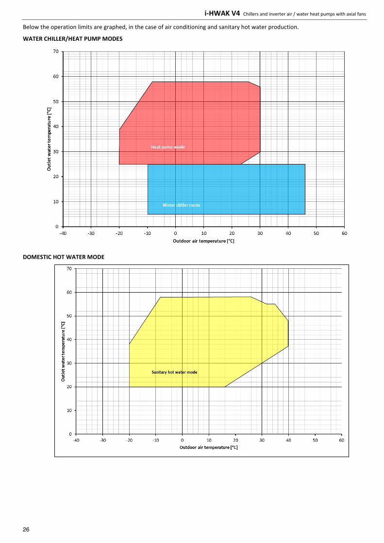
i-HWAK V4 Chillers and inverter air / water heat pumps with axial fans
26
Below the operation limits are graphed, in the case of air conditioning and sanitary hot water production.
WATER CHILLER/HEAT PUMP MODES
DOMESTIC HOT WATER MODE
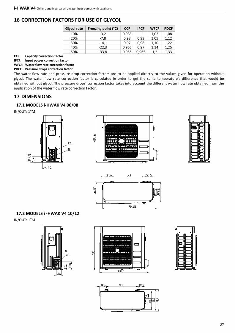
i-HWAK V4 Chillers and inverter air / water heat pumps with axial fans
27
16 CORRECTION FACTORS FOR USE OF GLYCOL Glycol rate Freezing point (°C) CCF IPCF WFCF PDCF
10% -3,2 0,985 1 1,02 1,08 20% -7,8 0,98 0,99 1,05 1,12 30% -14,1 0,97 0,98 1,10 1,22 40% -22,3 0,965 0,97 1,14 1,25 50% -33,8 0,955 0,965 1,2 1,33
CCF: Capacity correction factor IPCF: Input power correction factor WFCF: Water flow rate correction factor PDCF: Pressure drops correction factor The water flow rate and pressure drop correction factors are to be applied directly to the values given for operation without glycol. The water flow rate correction factor is calculated in order to get the same temperature’s difference that would be obtained without glycol. The pressure drops’ correction factor takes into account the different water flow rate obtained from the application of the water flow rate correction factor.
17 DIMENSIONS 17.1 MODELS i-HWAK V4 06/08
IN/OUT: 1”M
17.2 MODELS i -HWAK V4 10/12
IN/OUT: 1”M
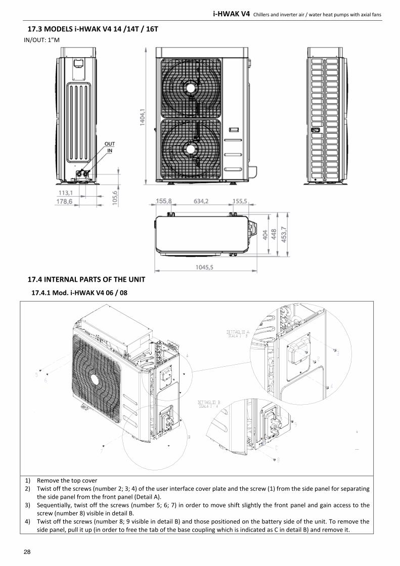
i-HWAK V4 Chillers and inverter air / water heat pumps with axial fans
28
17.3 MODELS i-HWAK V4 14 /14T / 16T IN/OUT: 1”M
17.4 INTERNAL PARTS OF THE UNIT
17.4.1 Mod. i-HWAK V4 06 / 08
1) Remove the top cover 2) Twist off the screws (number 2; 3; 4) of the user interface cover plate and the screw (1) from the side panel for separating
the side panel from the front panel (Detail A). 3) Sequentially, twist off the screws (number 5; 6; 7) in order to move shift slightly the front panel and gain access to the
screw (number 8) visible in detail B. 4) Twist off the screws (number 8; 9 visible in detail B) and those positioned on the battery side of the unit. To remove the
side panel, pull it up (in order to free the tab of the base coupling which is indicated as C in detail B) and remove it.
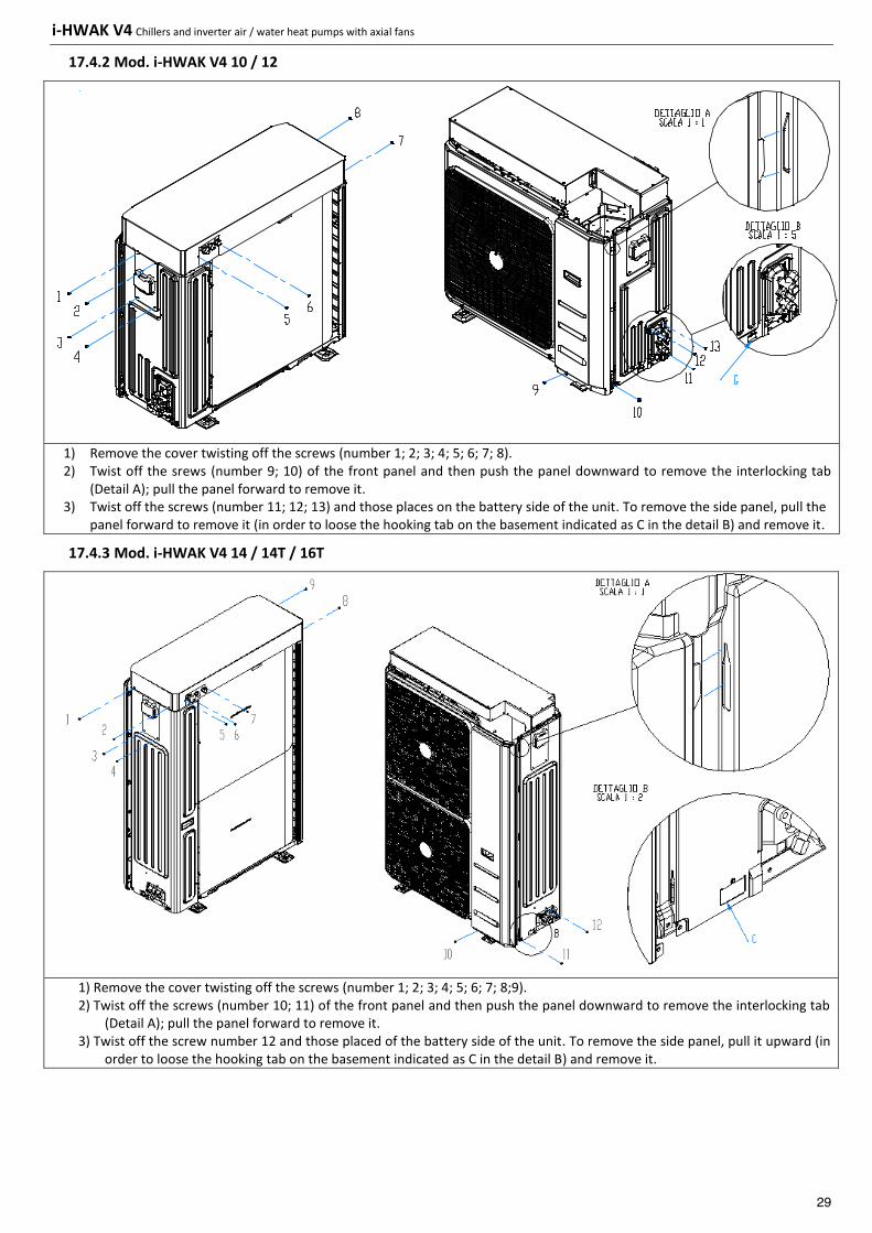
i-HWAK V4 Chillers and inverter air / water heat pumps with axial fans
29
17.4.2 Mod. i-HWAK V4 10 / 12
1) Remove the cover twisting off the screws (number 1; 2; 3; 4; 5; 6; 7; 8). 2) Twist off the srews (number 9; 10) of the front panel and then push the panel downward to remove the interlocking tab
(Detail A); pull the panel forward to remove it. 3) Twist off the screws (number 11; 12; 13) and those places on the battery side of the unit. To remove the side panel, pull the
panel forward to remove it (in order to loose the hooking tab on the basement indicated as C in the detail B) and remove it.
17.4.3 Mod. i-HWAK V4 14 / 14T / 16T
1) Remove the cover twisting off the screws (number 1; 2; 3; 4; 5; 6; 7; 8;9). 2) Twist off the screws (number 10; 11) of the front panel and then push the panel downward to remove the interlocking tab
(Detail A); pull the panel forward to remove it. 3) Twist off the screw number 12 and those placed of the battery side of the unit. To remove the side panel, pull it upward (in
order to loose the hooking tab on the basement indicated as C in the detail B) and remove it.
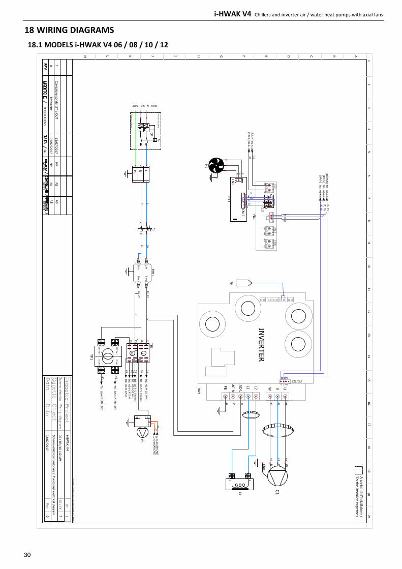
i-HWAK V4 Chillers and inverter air / water heat pumps with axial fans
30
18 WIRING DIAGRAMS 18.1 MODELS i-HWAK V4 06 / 08 / 10 / 12
C1
WVUGN
D
L1
1 2
Non fornito / N
ot supplied
Obbligatorio / O
bligatory
LNPE
230V - 1Ph - N - 50Hz
230 Vac1TF1 12 Vac1
230 Vac212 Vac2
FD1
CN13
CN3
PBF1
9M
1
4
11
3
LN
+-
P1
TO: 02-H
-7
TO: 02-H
-7
4240
12
LN
TB1
2529 3577 36 34
26
36
TO: 02-M
-10
TO: 02-J-20
02-C-1002-D
-1063
62
INVER
TER
UVWL2L1
AC-L
AC-N
PEINV1
4343
4646
L in
N in
L out
N out
EMI 1
QF
F1
21
141618TO: 01-F-5
01-K-15
TO: 01-F-5
01-K-15
44 24 22
8
10
5
35
4848
93, 22
23, 24
9323
17, 1615, 14
TO: 02-K-8
TO: 02-K-8
1719
19, 18TO
: 02-K-8
67
20
15
28TO
: 02-J-17TO
: 02-M-17
N°
DI / O
f
Rev.
12
34
56
78
910
1112
1314
1516
1718
1920
ABCDEFGHIJKLM
02/02/2017
1
3
00
02/02/2017AB
Emissione
MP
AB
06 / 08 /10 /12 kW
Schema elettrico funzionale / Functional electrical diagram
i-HW
AK_V4
3 21
[AB:I+]
[AB:I-]
[AB:GN
D]
[AB:12V]
[AB:12V]
[N1]
[CEH1]
[4WV1]
[Fd1:CN1]
[Fd1:CN1]
[AB:C1]
[T.B.:N]
[T.B.:L]
[AB:CN5]
[AB:CN5]
Tp
A carico dell'installatore /To the installer expenses
1Correzione sonde ST e O
UT
13/07/2017M
PAB
AB
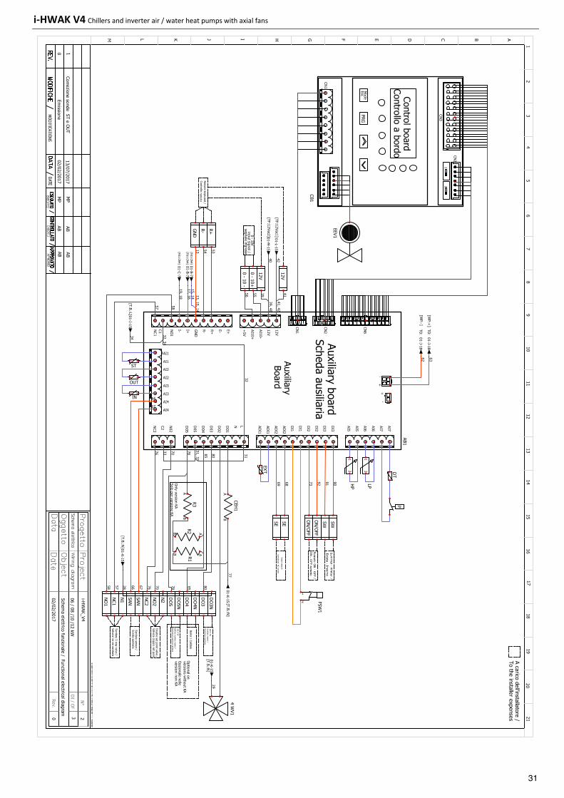
i-HWAK V4 Chillers and inverter air / water heat pumps with axial fans
31
ON
PRGM
odeEsc
ON
CB1
CN3
CN2
CN1
AuxiliaryBoard
AB1
CN6
CN2
CN112V
12V
AI10-
AI10+
+5V
E+E-R+
R-
GN
D
I+I-NO
1
C1NC1
AI1
AI1
AI2
AI2
AI3
AI3
AI4
AI4N
C2
C2
N02
DO
5
D05
DO
4
D03
DO
2
DO
1
N L ADI1
ADI1
ADI2
ADI2
DI1
DI1
DI2
DI2
DI3
DI3
AI5
AI5
AI6
AI6
AI7
AI7
-
+
+
-
21
DT
12
LP
12
HP
21
ST
21
OUT
21
IN
SAN
SAN
6766
SW SW9091
ON
/OFF
ON
/OFF
9273
FSW1
1
2
69 68SESE
21
EXT
31, 33
31
3332, 34
34
EEV1
NC1
NO
1
57
32
4240
01-L-15
01-M-15
12V
12V39
39, 40
41
41, 42
NC2
NO
2
70
R+R-
53
0 - 10 -
0 - 10+
GN
D
19, 18
17, 1615, 14 13, 15, 14
4 WV1
29
62 63TO
: 01-J-18
TO: 01-J-18
DO
4N
DO
3
DO
5N
80
DO
5
DO
4
DO
3N
CEH1
AB
80
R3
AB
R1
AB
R2 AB
78
78
N2
76
7667
66
58
N1
57
Auxiliary heater /
Boiler / Caldaia
Resistenza ausiliaria sanitariaSanitary auxiliary heater /
Double setpoint
humidostat N
C contact
Remote keyboard /
Sanitary sensor /
Double set point valve /
Sanitary 3 way valve /
V01-
0input signal /
70
5556
5413
01-J-15
01-K-15
58
01-B-701-B-7
01-C-7
85
85
28
01-K-15
01-K-15
77
N°
DI / O
f
Rev.
12
34
56
78
910
1112
1314
1516
1718
1920
ABCDEFGHIJKLM
02/02/2017
2
3
00
02/02/2017AB
Emissione
MP
AB
06 / 08 /10 /12 kW
Schema elettrico funzionale / Functional electrical diagram
i-HW
AK_V4
3 21
[WP:+
]
[WP:-]
[T.B.:L]
[TF:12Vac1]
[TF:12Vac2]
[T.B.:N]
[T.B.:N]
[T.B.:N]
[Fd1:CN4]
[Fd1:CN4]
[Fd1:CN4]
Solo per versione KA
Opzionale nelle
versioni non KA
To the installer expensesA carico dell'installatore /
P
Only version KA
versions without KA
Optional on
Resistenza ausiliaria
230 V 5A
230 V 5A
Valvola doppio set point
Sonda sanitaria
Valvola tre vie sanitaria
oto
mer
ollor
tno
C
segnale ingresso
Auxiliary boardScheda ausiliaria
Control boardControllo a bordo
1Correzione sonde ST e O
UT
13/07/2017M
PAB
AB
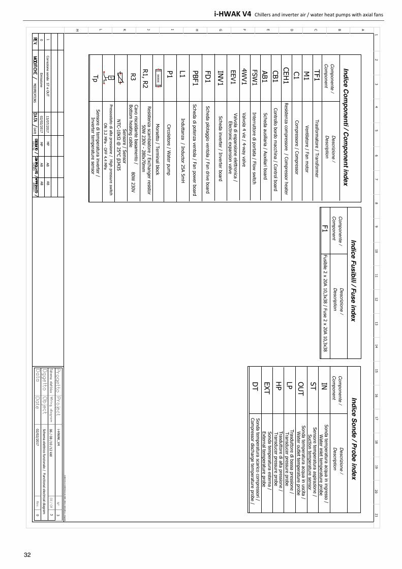
i-HWAK V4 Chillers and inverter air / water heat pumps with axial fans
32
TF1M
1C1
CEH1
CB1AB1FSW
1
AB
xxxxx
EEV1
Indice Com
ponenti / Com
ponent index
Com
ponente /C
omponent
Description
Descrizione /
Trasformatore / Transform
er
Ventilatore / Fan motor
Compressore / Com
pressor
Resistenza compressore / Com
pressor heater
Scheda ausiliaria / Auxiliari board
Interruttore di portata / Flow sw
itch
Morsetto / Term
inal block
Valvola di espansione elettronica /
Controllo bordo macchina / Control board
Electronic expansion valve
Descrizione /
Description
Com
ponentC
omponente /
F1
Indice Fusibili / Fuse index
Fusibile 2 x 20A 10,3x38 / Fuse 2 x 20A 10,3x38
Trasduttore di bassa pressione /
Sensore temperatura aspirazione /
Sonda temperatura acqua in ingresso /
Descrizione /
Description
Com
ponentC
omponente /
HP
LP OU
T
ST IN
Indice Sonde / Probe index
Sonda temperatura esterna /
Sonda temperatura scarico com
pressori /
EXT
DT
Water inlet tem
perature probe
Suction temperature sensor
Sonda temperatura acqua in uscita /
Water outlet tem
perature probe
Transducer pressure probeTrasduttore di alta pressione /Transducer pressure probe
External temperature probe
Compressor discharge tem
perature probe /N°
DI / O
f
Rev.
12
34
56
78
910
1112
1314
1516
1718
1920
ABCDEFGHIJKLM
02/02/2017
3
3
00
02/02/2017AB
Emissione
MP
AB
06 / 08 /10 /12 kW
Schema elettrico funzionale / Functional electrical diagram
i-HW
AK_V4
3 21
4WV1
Valvola 4 vie / 4-way valve
R1, R
250W
230V - 280x70mm
Resistenza scambiatore / Exchanger resistor
R3
Cavo riscaldante basamento /
80W 230V
Sensore / SensorN
TC-10kΏ @
25°C β34352
1.
PPressostato di alta pressione / H
igh pressure switch
ON
3.2 MPa - O
FF 4.4 MPa
Bottom heating cable
INV1
FD1
PBF1
L1P1
Scheda inverter / Inverter board
Scheda pilotaggio ventola / Fan drive board
Scheda di potenza ventola / Fan power board
Circolatore / Water pum
p
Induttanza / Inductor 25A 5mH
TpSensore di tem
peratura inverter /Inverter tem
perature sensor
1Correzione sonde ST e O
UT
13/07/2017M
PAB
AB
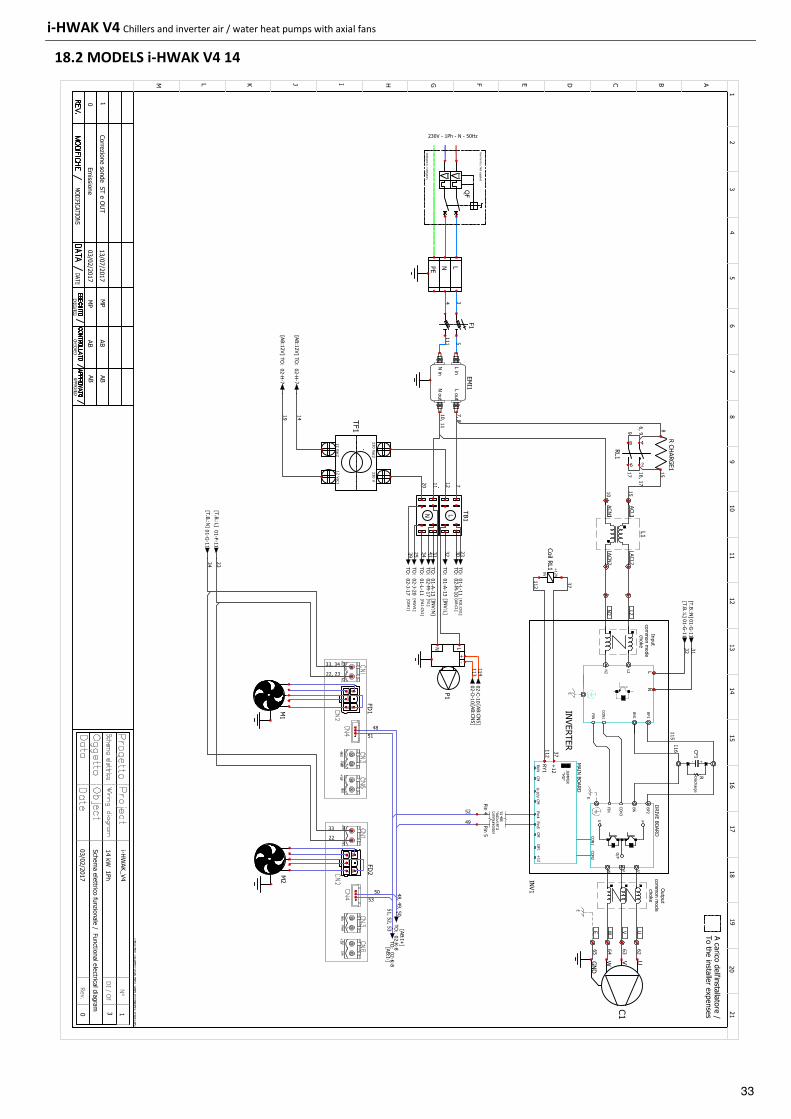
i-HWAK V4 Chillers and inverter air / water heat pumps with axial fans
33
18.2 MODELS i-HWAK V4 14
FD1
FD2
22
33
LN TB1
230 V
TF1
12 Vac1
230 Vac2
12 Vac2
LN
+-
P1L in
N in
L out
N out
EMI1
F1
Non fornito / N
ot supplied
230V - 1Ph - N - 50Hz
Obbligatorio / O
bligatory
QF
PE N L
ACL1ACL2
ACN1
ACN2
L1
Output
comm
on mode
choke
RDischarge
CF1+-
Input
chokecom
mon m
ode
JUM
PER"M
D"
MAIN
BOARD
E
E
UVW
O/P
PU
DRIV
E BOARD
CON
1CO
N2
FIN
CON
3
BN BP2
RUN
CMCM
CM0-10V
Pin4Pin5
OP1
+12
L2N2
E
CON
1
FIN
BP1
BN1
L2
N2
+12
RY1
UVWE
LN
Pin 4Pin 5
INV1
RL1
2
4
6
8
R CHARG
E1
114
303234 3141
1517 16, 17
8
7, 8
Coil RL137
37
112
112
+12V
0V
32
48
C1
UVWGN
D
63
20 7
10
1110, 11
12
19
TO: 01-A-13
01-G-11
TO: 01-A-13
01-G-11
TO: 02-H
-7
TO: 02-H
-7
TO: 01-L-11
01-G-11
TO: 01-L-11
01-F-11
TO: 02-M
-10
25TO
: 02-J-20
51
33, 34
22, 23
113
23
111 5
4 3
31
626465
2334
14
53
50
39
02-D-10
02-C-10
TO: 02-J-17
TO: 02-M
-17
N°
DI / O
f
Rev.
12
34
56
78
910
1112
1314
1516
1718
1920
ABCDEFGHIJKLM
03/02/2017
1
3
00
03/02/2017AB
Emissione
MP
AB
14 kW 1Ph
Schema elettrico funzionale / Functional electrical diagram
i-HW
AK_V4
3 21
915
115116
6, 9
49
48, 49, 50
52
51, 52, 53TO
: 02-K-8TO
: 02-K-8
[AB:12V]
[AB:12V]
[T.B.:L]
[T.B.:N]
[AB:CN5]
[AB:CN5]
[AB:I-]
[AB:I+]
[T.B.:N]
[T.B.:L]
[AB:C1][Fd1:CN
1]
[INV:L]
[INV:N
]
[4WV1]
[CEH1]
[N1]
[Fd1:CN1]
INVERTER
A carico dell'installatore /To the installer expenses
M2
M1
1Correzione sonde ST e O
UT
13/07/2017M
PAB
AB
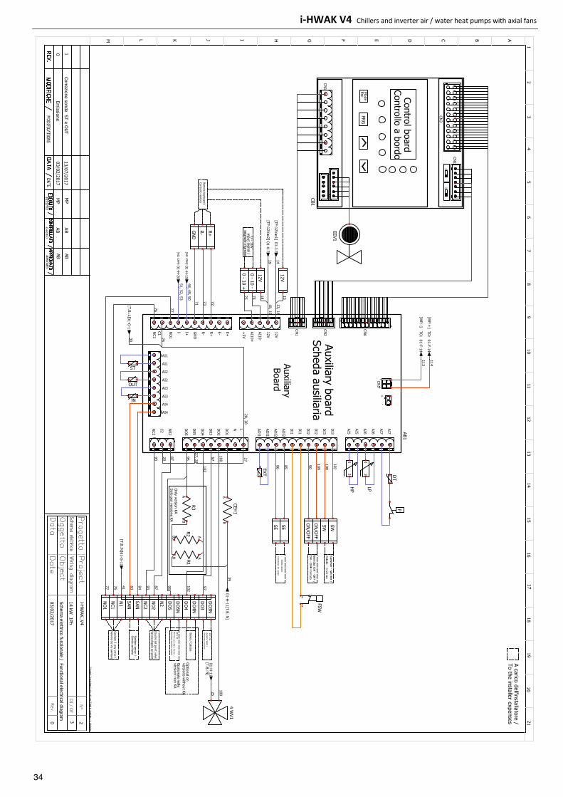
i-HWAK V4 Chillers and inverter air / water heat pumps with axial fans
34
ON
PRGM
odeEsc
ON
CB1
CN
3
CN
2
CN
1
AuxiliaryBoard
AB1
CN
6
CN
2
CN
1
12V
12V
AI10-
AI10+
+5V
E+E-R+
R-
GN
D
I+I-NO
1
C1NC
1
AI1
AI1
AI2
AI2
AI3
AI3
AI4
AI4N
C2
C2
N02
DO
5
D05
DO
4
D03
DO
2
DO
1
N L AD
I1
AD
I1
AD
I2
AD
I2
DI1
DI1
DI2
DI2
DI3
DI3
AI5
AI5
AI6
AI6
AI7
AI7
-
+
+
-
21
DT
12
LP
12
HP
21
ST
21
OUT
21
IN
SAN
SAN
8483
SW SW
ON
/OFF
ON
/OFF
FSW
1
2
SESE
21
EXT
27, 29
27
292830
EEV1
NC1
NO
1
76
28, 30
1419
12V
12V18
18, 19
13
13, 14
NC2
NO
2
87
R+R-
7273
0 - 10 +
0 - 10 -
GN
D
51, 52, 53
48, 49, 50
71
100100
4 WV1
25
113
114
DO
4N
DO
3
DO
5N
97
DO
5
DO
4
DO
3N
CEH1
AB
97
R3
AB
R1
AB
R2 AB
102
95
95
N2
93
93
77
N1
76 87
7475
7 01108
109
908586
77
01-J-7
01-K-7
01-G-11
01-H-11
TO: 01-F-14
TO: 01-F-14
102
41
01-H-11
01-G-11
39
N°
DI / O
f
Rev.
12
34
56
78
910
1112
1314
1516
1718
1920
ABCDEFGHIJKLM
03/02/2017
2
3
00
03/02/2017AB
Emissione
MP
AB
14 kW 1Ph
Schema elettrico funzionale / Functional electrical diagram
i-HW
AK_V4
3 21
01-H-20
01-H-19
[T.B.:N]
[T.B.:N]
[T.B.:N]
CN
5
[WP:-]
[WP:+
]
[TF:12Vac2]
[TF:12Vac1]
[Fd1:CN4]
[Fd1:CN4]
[T.B.:L]
To the installer expensesA carico dell'installatore /
P
Auxiliary boardScheda ausiliaria
Control boardControllo a bordo
230 V 5AAuxiliary heater /Resistenza ausiliaria
Boiler / Caldaia
/r
eta
eh
yrail
ixu
ayr
a ti
naSResistenza ausiliaria sanitaria
230 V 5A
Optional on
versions without KA
versioni non KAO
pzionale nelle
tnio
ptes
oipp
odal
ovla
V Double set point valve /
Sonda sanitariaSanitary sensor /
Valvola tre vie sanitariaSanitary 3 w
ay valve /
Only version KA
Solo per versione KA
Remote keyboard /
Controllo remoto
0 - 10V
segnale ingressoinput signal /
Double setpoint
humidostat N
C contact
1Correzione sonde ST e O
UT
13/07/2017M
PAB
AB
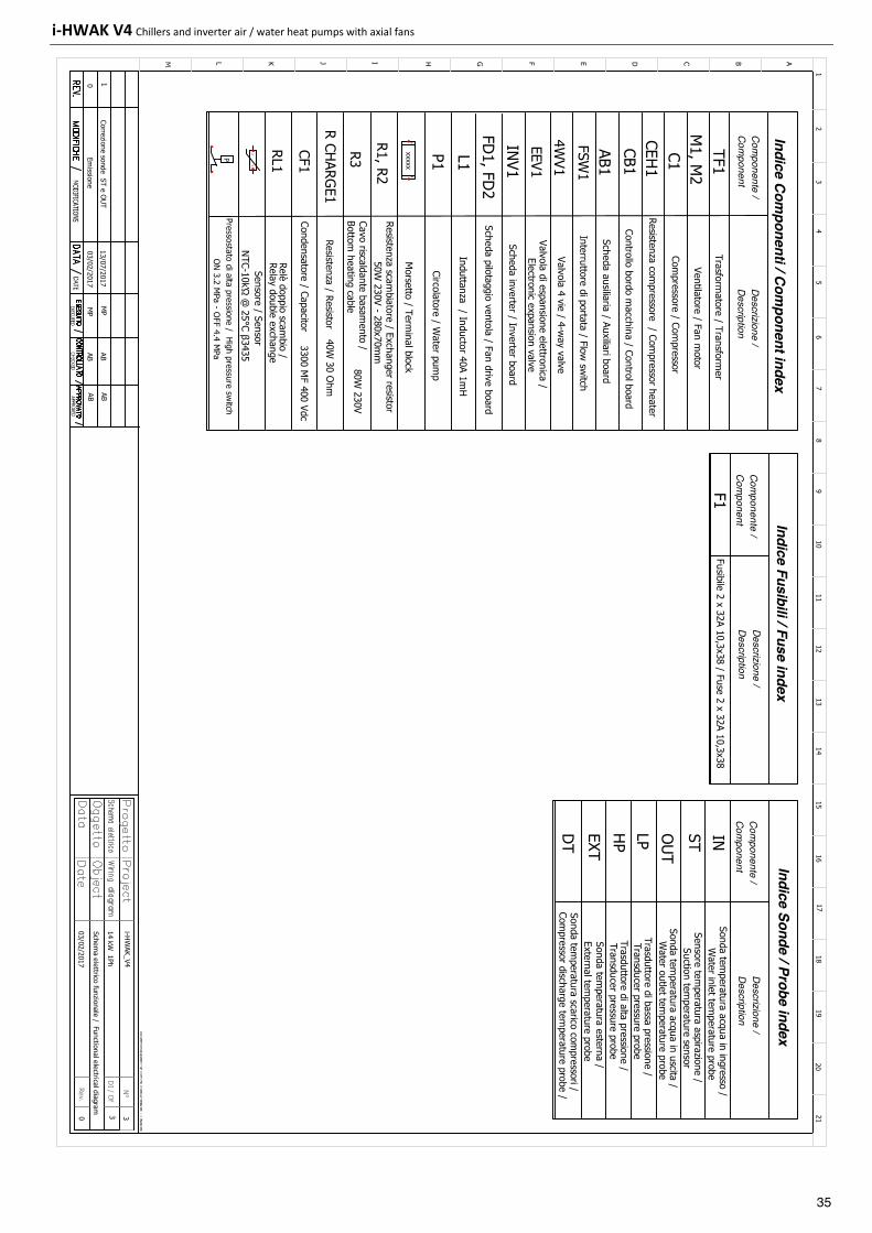
i-HWAK V4 Chillers and inverter air / water heat pumps with axial fans
35
N°
DI / O
f
Rev.
12
34
56
78
910
1112
1314
1516
1718
1920
ABCDEFGHIJKLM
03/02/2017
3
3
00
03/02/2017AB
Emissione
MP
AB
14 kW 1Ph
Schema elettrico funzionale / Functional electrical diagram
i-HW
AK_V4
3 21
Trasduttore di alta pressione /Transducer pressure probe
Water outlet tem
perature probeSonda tem
peratura acqua in uscita /Suction tem
perature sensor
Water inlet tem
perature probe
DescriptionDescrizione /
Sonda temperatura acqua in ingresso /
Sensore temperatura aspirazione /
Trasduttore di bassa pressione /
INSTOU
T
LP
Component
DescriptionDescrizione /
Indice Sonde / Probe index
Componente /
Compressor discharge tem
perature probe /
External temperature probe
DT
EXTSonda tem
peratura scarico compressori /
Sonda temperatura esterna /
Transducer pressure probeH
P
F1
Componente /
Component
Fusibile 2 x 32A 10,3x38 / Fuse 2 x 32A 10,3x38
Indice Fusibili / Fuse index
Resistenza compressore / Com
pressor heater
Compressore / Com
pressor
Ventilatore / Fan motor
Trasformatore / Transform
er
Descrizione /Description
Indice Com
ponenti / Com
ponent index
Controllo bordo macchina / Control board
Component
Componente /
CEH1
C1M
1, M2
TF1
80W 230V
P1 L1
FD1, FD
2
INV1
4WV1
EEV1
FSW1
AB1
Bottom heating cable
P
R1, R2
R321
.
AB
xxxxx
Cavo riscaldante basamento /
50W 230V - 280x70m
mResistenza scam
biatore / Exchanger resistor
Circolatore / Water pum
p
Induttanza / Inductor 40A 1mH
Scheda pilotaggio ventola / Fan drive board
Scheda inverter / Inverter board
Pressostato di alta pressione / High pressure sw
itchO
N 3.2 M
Pa - OFF 4.4 M
Pa
NTC-10kΏ
@ 25°C β3435
Sensore / Sensor
Valvola 4 vie / 4-way valve
Electronic expansion valveValvola di espansione elettronica /
Morsetto / Term
inal block
Interruttore di portata / Flow sw
itch
Scheda ausiliaria / Auxiliari board
CB1
R CHARG
E1
CF1
Resistenza / Resistor40W
30 Ohm
Condensatore / Capacitor3300 M
F 400 Vdc
RL1Relè doppio scam
bio / Relay double exchange
1Correzione sonde ST e O
UT
13/07/2017M
PAB
AB
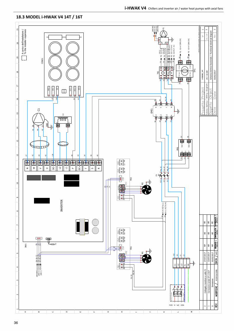
i-HWAK V4 Chillers and inverter air / water heat pumps with axial fans
36
18.3 MODEL i-HWAK V4 14T / 16T
RSTPL1 DC+L2DC-N UVW
INV1
DC+
DC
-
DC
1 +
DC
2 +
DC1
-
DC2
-
CON
D1
C1
W V U GN
D
4545
27
42
L1
12
L1R
L2S
L3T
NN
EMI1
403934
Non
for
nito
/ N
ot s
uppl
ied
Obb
ligat
orio
/ O
blig
ator
y
Id Id Id
L1 L2 L3 N PE
400V - 3Ph - N - 50Hz
PM1
L1 L2 L3
Out
11
Out
14
10
230
Vac1
TF112
Vac
1
230
Vac2
12 V
ac2
32
46 47 48
40 31, 3
4
4444
4949
77
7673
74
66 FD1
FD2
M1
53, 5
2
112
14 11 12
12
14
39
42 4343
131560 58
65
75, 7
3, 7
4
L N
+-
P1
TO:
02-
H-7
TO:
02-
H-7
02-K
-8
27
L NTB1
33 35
35
5653 104
5551
3231
55, 5
4
55 53TO
: 0
1-K-
801
-K-1
9
TO:
01-
K-8
01-L
-19
TO:
02-
M-1
0
TO:
02-
J-20
118
118
02-C
-10
02-D
-10
33
83 82
2626
TO:
02-
J-17
41TO
: 0
2-M
-17
N°
DI
/ O
f
Rev.
12
34
56
78
910
1112
1314
1516
1718
1920
A B C D E F G H I J K L M
03/0
2/20
17
1
3
2
227
/07/
2017
ABM
P
1M
PAB
003
/02/
2017
AB
13/0
7/20
17
Emis
sion
eM
P
AB AB AB
14 /
16
kW
Sche
ma
elet
tric
o fu
nzio
nale
/ F
unct
iona
l ele
ctric
al d
iagr
am
i-HW
AK_V
4
321
6767
, 65,
66
02-K
-8
02-K
-878 75
78, 7
6, 7
7
[AB:
CN5]
[AB:
CN5]
[AB:
12V]
[AB:
12V]
[Fd1
:CN
1]
[AB:
C1]
[T.B
.:N
]
[T.B
.:L]
[Fd1
:CN
1]
[N1]
[CEH
1]
[4W
V1]
[AB:
GN
D]
[AB:
I-]
[AB:
I+]
INVE
RTER
Tp
To t
he in
stal
ler
expe
nses
A ca
rico
dell'i
nsta
llato
re /
M2
Corr
ezio
ne s
onde
ST
e O
UT
AB
CD
EF
F1
13, 4
7
48, 1
0
112
46, 1
5
11
Colle
gato
mon
itore
a v
alle
F1
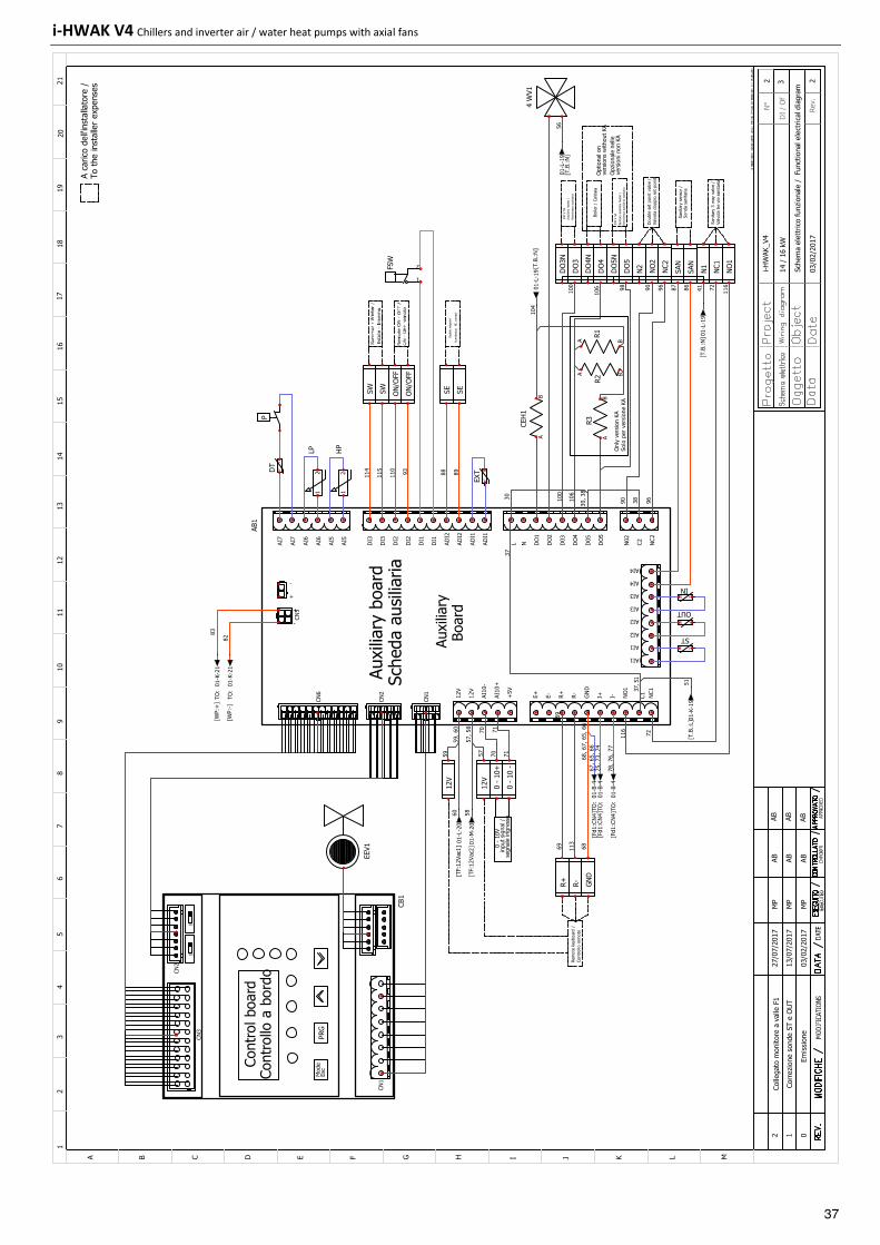
i-HWAK V4 Chillers and inverter air / water heat pumps with axial fans
37
ONPR
GM
ode
Esc
ON
CB1
CN3
CN2
CN1
Auxi
liary
Boar
d
AB1
CN6
CN2
CN1
12V
12V
AI10
-
AI10
+
+5V
E+ E- R+
R-
GN
D
I+ I- NO
1
C1 NC1
AI1
AI1
AI2
AI2
AI3
AI3
AI4
AI4
NC2
C2
N02
DO
5
D05
DO
4
D03
DO
2
DO
1
NLADI1
ADI1
ADI2
ADI2
DI1
DI1
DI2
DI2
DI3
DI3
AI5
AI5
AI6
AI6
AI7
AI7
-
+
+
-
21
DT
12
LP
12
HP
2 1
ST
2 1
OUT
2 1
IN
SAN
SAN
87 86
SWSW11
4
115
ON
/OFF
ON
/OFF
110 93
FSW
1
2
8988SE SE
21
EXT
30, 3
8
30
3815,73
51
EEV1
NC1
NO
1
72
37
60 5801
-L-2
0
01-M
-20
12V
12V
57
57, 5
8
59
59, 6
0
NC2
NO
2
90
R+ R-11
3
0 -
10 -
0 -
10+
70 71
GN
D
78, 7
6, 7
7
75, 7
3, 7
467
, 65,
66
6868
, 67,
65,
66
TO:
01-
B-4
4 W
V1
56
82
83TO
: 0
1-K-
21
TO:
01-
K-21
DO
4N
DO
3
DO
5N
100
DO
5
DO
4
DO
3N
CEH
1
AB
100
R3
AB
R1
A B
R2
A B
106
98
N2
96
96
116
N1
7290
70 71
01-K
-19
01-L
-19
116
10601
-L-1
9
4101
-L-1
9
104
N°
DI
/ O
f
Rev.
12
34
56
78
910
1112
1314
1516
1718
1920
A B C D E F G H I J K L M
03/0
2/20
17
2
3
2
227
/07/
2017
ABM
P
1M
PAB
003
/02/
2017
AB
13/0
7/20
17
Emis
sion
eM
P
AB AB AB
14 /
16
kW
Sche
ma
elet
tric
o fu
nzio
nale
/ F
unct
iona
l ele
ctric
al d
iagr
am
i-HW
AK_V
4
321
TO:
01-
B-4
TO:
01-
B-4
[T.B
.:N
]
[Fd1
:CN
4][F
d1:C
N4]
[Fd1
:CN
4]
[T.B
.:L]
[T.B
.:N
]
[T.B
.:N
]
[WP:
-]
[WP:
+]
[TF:
12Va
c1]
[TF:
12Va
c2]
CN5
6969
A ca
rico
dell'i
nsta
llato
re /
To t
he in
stal
ler
expe
nses
PCo
ntro
llo a
bor
doCo
ntro
l boa
rd
Sche
da a
usili
aria
Auxi
liary
boa
rd
inpu
t si
gnal
/0
- 10
V
segn
ale
ingr
esso
Rem
ote
keyb
oard
/Co
ntro
llo r
emot
o
Dou
ble
setp
oint
hum
idos
tat
NC
cont
act
230
V 5A
Resi
sten
za a
usili
aria
Auxi
liary
hea
ter
/
Boile
r /
Cald
aia
230
V 5A
Sani
tary
aux
iliar
y he
ater
/Re
sist
enza
aus
iliar
ia s
anita
ria
Dou
ble
set
poin
t va
lve
/Va
lvol
a do
ppio
set
poi
nt
Sond
a sa
nita
riaSa
nita
ry s
enso
r /
Valv
ola
tre
vie
sani
taria
Sani
tary
3 w
ay v
alve
/
Opt
iona
l on
vers
ions
with
out KA
vers
ioni
non
KA
Opz
iona
le n
elle
Onl
y ve
rsio
n KA
Solo
per
ver
sion
e KA
Corr
ezio
ne s
onde
ST
e O
UT
Colle
gato
mon
itore
a v
alle
F1
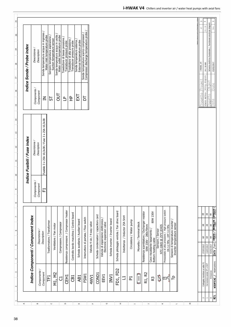
i-HWAK V4 Chillers and inverter air / water heat pumps with axial fans
38
N°
DI
/ O
f
Rev.
12
34
56
78
910
1112
1314
1516
1718
1920
A B C D E F G H I J K L M
03/0
2/20
17
3
3
2
227
/07/
2017
ABM
P
1M
PAB
003
/02/
2017
AB
13/0
7/20
17
Emis
sion
eM
P
AB AB AB
14 /
16
kW
Sche
ma
elet
tric
o fu
nzio
nale
/ F
unct
iona
l ele
ctric
al d
iagr
am
i-HW
AK_V
4
321
Tran
sduc
er p
ress
ure
prob
e
Tras
dutt
ore
di b
assa
pre
ssio
ne /
Sens
ore
tem
pera
tura
asp
irazi
one
/
Sond
a te
mpe
ratu
ra a
cqua
in in
gres
so /
Des
crizi
one
/De
scrip
tion
Wat
er in
let
tem
pera
ture
pro
be
Suct
ion
tem
pera
ture
sen
sor
Sond
a te
mpe
ratu
ra a
cqua
in u
scita
/W
ater
out
let
tem
pera
ture
pro
be
Tran
sduc
er p
ress
ure
prob
eTr
asdu
ttor
e di
alta
pre
ssio
ne /
HP
Desc
rizio
ne /
Desc
riptio
n
LPOU
T
STIN
Com
pone
nte
/
Indi
ce S
onde
/ Pr
obe
inde
x
Com
pone
nt
Sond
a te
mpe
ratu
ra s
caric
o co
mpr
esso
ri /
DT
Exte
rnal
tem
pera
ture
pro
be
Com
pres
sor
disc
harg
e te
mpe
ratu
re p
robe
/
Sond
a te
mpe
ratu
ra e
ster
na /
EXT
Com
pone
ntCo
mpo
nent
e /
F1
CB1
TF1
M1,
M2
C1CE
H1
Com
pone
nte
/Co
mpo
nent
Cont
rollo
bor
do m
acch
ina
/ Co
ntro
l boa
rd
Indi
ce C
ompo
nent
i / C
ompo
nent
inde
x
Desc
riptio
nDe
scriz
ione
/
Tras
form
ator
e /
Tran
sfor
mer
Vent
ilato
re /
Fan
mot
or
Com
pres
sore
/ C
ompr
esso
r
Resi
sten
za c
ompr
esso
re
/ Co
mpr
esso
r he
ater
AB1
FSW
1
AB
xxxx
x
EEV1
Sche
da a
usili
aria
/ A
uxili
ari b
oard
Inte
rrut
tore
di p
orta
ta /
Flo
w s
witc
h
Mor
sett
o /
Term
inal
blo
ck
Valv
ola
di e
span
sion
e el
ettr
onic
a /
Elec
tron
ic e
xpan
sion
val
ve
4WV1
Valv
ola
4 vi
e /
4-w
ay v
alve
Indi
ce F
usib
ili /
Fuse
inde
x
Fusi
bile
3 x
25A
10,
3x38
/ F
use
3 x
25A
10,3
x38
CON
D1
Sche
da c
onde
nsat
ori /
cap
acito
rs c
ard
Sens
ore
/ Se
nsor
NTC
-10k
Ώ @
25°
C β3
435
21
.R3
R1,
R2
ON
3.2
MPa
- O
FF 4
.4 M
PaPr
esso
stat
o di
alta
pre
ssio
ne /
H
igh
pres
sure
sw
itch
P
INV1
Sche
da in
vert
er /
Inv
erte
r bo
ard
FD1,
FD
2Sc
heda
pilo
tagg
io v
ento
la /
Fan
driv
e bo
ard
L1In
dutt
anza
/
Indu
ctor
25A
5m
H
P1Ci
rcol
ator
e /
Wat
er p
ump
Resi
sten
za s
cam
biat
ore
/ Ex
chan
ger
resi
stor
50W
230
V -
280x
70m
mCa
vo r
isca
ldan
te b
asam
ento
/Bo
ttom
hea
ting
cabl
e80
W 2
30V
Sens
ore
di t
empe
ratu
ra in
vert
er /
Inve
rter
tem
pera
ture
sen
sor
Tp
Corr
ezio
ne s
onde
ST
e O
UT
Colle
gato
mon
itore
a v
alle
F1
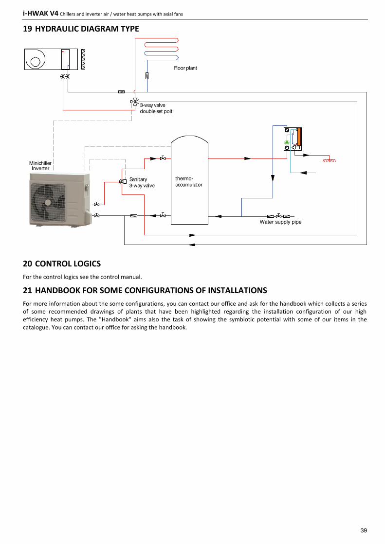
i-HWAK V4 Chillers and inverter air / water heat pumps with axial fans
39
19 HYDRAULIC DIAGRAM TYPE
Floor plant
thermo-accumulator
Water supply pipe
MSI
MinichillerInverter
3-way valvedouble set poit
Sanitary3-way valve
20 CONTROL LOGICS For the control logics see the control manual.
21 HANDBOOK FOR SOME CONFIGURATIONS OF INSTALLATIONS For more information about the some configurations, you can contact our office and ask for the handbook which collects a series of some recommended drawings of plants that have been highlighted regarding the installation configuration of our high efficiency heat pumps. The "Handbook" aims also the task of showing the symbiotic potential with some of our items in the catalogue. You can contact our office for asking the handbook.
The data indicated in this manual is purely indicative. The ma-nufacturer reserves the right to modify the data whenever it is considered necessary.
Via S. Giuseppe Lavoratore, 2437040 Arcole Verona - Italy
Tel. +39 - 045.76.36.585 r.a.Fax +39 - 045.76.36.551 r.a.
www.maxa.ite-mail: [email protected]
A I R C O N D I T I O N I N G