UNI EN 161 UNI-EN 161 series marked GECA 2014/68/UE · Attacchi filettati secondo ISO 228/1 Corpo...
2
Simboli che identificano i connettori “raddrizzatori” (vedi Timbratura bobine) - Identification symbol of the “rectifier” connectors (see table coil marking). 1 2 3 4 5 6 EV N.C. Queste elettrovalvole sono nate per essere abbinate a qualunque sistema di rivelazione gas che preveda, in caso d’allarme, un segnale per la chiusura della mandata principale. Tutte le elettrovalvole sono a riarmo manua- le in accordo con la normativa italiana riguardante i sistemi di rivelazione gas CEI UNI EN 50194. PRINCIPIO DI FUNZIONAMENTO Normalmente Aperte (N.A.) Nelle elettrovalvole Normalmente Aperte durante il normale esercizio non c’è assorbimento elettrico e quindi, oltre al risparmio energetico, nessun organo è sottoposto ad usura. Quando invece la bobina elettromagnetica è sottoposta a tensione viene sganciato il dispositivo di chiusura. Per riarmare l’elettrovalvola assicurarsi che la bobina NON sia alimentata . Per i modelli da 550mbar (da DN15 a DN50) e da 550mbar/6bar (da DN65 a DN100), tirare la manopola di riarmo, mentre per i modelli 6bar (da DN15 a DN50) svitare il “ Tappo di prote- zione ”, spingere la manopola di riarmo e riavvitare il “ Tappo di protezione ”. Normalmente Chiuse (N.C.) Le elettrovalvole Normalmente Chiuse sono costruite in modo tale da poter garantire, con la loro sicurezza intrinseca , l’intercettazione del gas in mancanza di tensione di rete. Esse infatti hanno bisogno di essere con- tinuamente alimentate per rimanere aperte e si chiudono automaticamente se viene a mancare tensione alla bobina. Per evitare chiusure accidentali, le elettrovalvole sono dotate di un meccanismo che ignora le interruzioni di corrente di breve durata (<30 msec). Per riarmare l’elettrovalvola assicurarsi che la bobina sia alimentata. Per i modelli da 550mbar (da DN15 a DN50 ) svitare il “ Tappo di protezione ”, spingere la manopola di riarmo e riavvitare il “ Tappo di protezione ”. Per i modelli 550mbar/6bar (da DN65 a DN100 ) svitare il “ Tappo di protezione ”, e tramite il “ Foro filettato” , avvitarlo sul “ Perno di chiusura” , per utilizzarlo come manopola di riarmo. Tirare quindi il “ Tappo di protezione ” per rimanere l’elettrovalvola. Riarmata l’elettrovalvola svitare il “ Tappo di protezione ” e riavvitarlo in “ Posizione di protezione ”. These solenoid valves have been designed to be combined with any gas detection system which sets off a warning signal to shut off the main delivery when an emergency situation is detected. All solenoid valves are reset manually in compliance with european standard EN 50194 governing gas detection system. OPERATING PRINCIPLE Normally Open (N.O.) There is no electrical absorption during normal operation and so no part of the system undergoes wear; there is no annoying buzzing or vibrations, and energy is saved. However, when voltage is applied to the electroma- gnetic coil, the closure mechanism is released. To reset the solenoid valve, check that the coil is not receiving current . For the valves 550mbar (from DN15 to DN50 ) and from 550mbar/6bar (from DN65 to DN100 ) pull the reset knob, For the valves 6bar (from DN15 to DN50 ) unscrew the “ Protective plug” and pull upwards the reset knob and after that screw the“ Protective plug”. Normally Closed (N.C.) The intrinsic accuracy of these models guarantee that gas will be cut off should the power supply fail. Consequently, a permanent power supply is required to keep the valve open. As soon as power across the coil is cut off, the valve shuts automatically. To avoid accidental closure, the valves are fitted with a mechanism that ignores interruptions to current of short duration (< 30msec). To reset the solenoid valve, check that the coil is receiving current . For the valves 550mbar (from DN15 to DN50 ) unscrew the “ Protective plug” and pull upwards the reset knob and after that screw the“ Protective plug”. For the valves 550mbar/6bar (from DN65 to DN100 ) pull the reset knob unscrew the “ Protective plug” and through the “ Threaded hole ”, screw it on the “ Closing joint ” in order to resetting the valve. Therefore pull the “ Protective plug” for resetting the valve. When valve is resetted unscrew the “ Protective plug” and screw in “ Protective position”. ø AxB N.A./ N.O AxB N.C. Pmax/Max pressure: 550 mbar/6bar Misure d’ingombro in mm Attacchi filettati secondo ISO 228/1 Corpo in ottone. Overall measurements in mm. Threaded connections as ISO 228/1 Body in brass. Misure d’ingombro in mm Attacchi filettati secondo ISO 228/1 Corpo in ottone. Overall measurements in mm. Threaded connections as ISO 228/1 Body in brass. Misure d’ingombro in mm. Attacchi flangiati secondo UNI 2223 Corpo in alluminio. Overall measurements in mm. Flanging connections as UNI 2223 Body in aluminium. 60x135 60x135 78x160 114x186 114x186 139x193 60x120 60x120 78x125 114x174 114x174 139x182 A 1 Connettore per il collegamento elettrico / Electric connector 2 Manopola di riarmo / Reset knob 3 Gruppo di scatto / Release unit 4 Corpo valvola / Valve body 5 Dado per il fissaggio della bobina / Screw for coil clamp 6 Bobina / Coil 7 Tappo di protezione / Protective plug 8 Foro filettato / Threaded hole 9 Perno di chiusura / Closing joint EV N.A./N.O. EV N.A./N.O. 550 mbar 6 bar 550 mbar 6 bar 6 1 2 3 4 5 7 ø DN15 - 1/2” DN20 - 3/4” DN25 - 1” DN32 - 1” 1/4 DN40 - 1” 1/2 DN50 - 2” PED EN161 PED EN161 V V V V V V V V V V V V V V V V Pmax/Max pressure: 550 mbar ø AxB N.A./ N.O AxB N.C. 60x135 60x135 78x160 114x186 114x186 139x193 60x140 60x140 78x165 114x195 114x195 139x210 DN15 - 1/2” DN20 - 3/4” DN25 - 1” DN32 - 1” 1/4 DN40 - 1” 1/2 DN50 - 2” PED EN161 PED V V V V V V V V V V Pmax/Max pressure: 6 bar EN161 V V V V V V ø AxB N.A./ N.O AxB N.C. 246x390 265x390 265x420 246x415 265x415 265x425 DN65 DN80 DN100 PED EN161 PED V V V EN161 A B Descrizione/Description EV N.A./N.O. 4 5 1 6 3 7 8 2 9 Direttiva PED 2014/68/UE EV N.C. A B ø 1 2 3 4 6 5 B B A ø ø GAS SOLENOID VALVES with manual reset, Normally Open and Normally Closed V V V 230V / 24V /12V C1+ C 2- V V V Dimensioni/ Dimensions Questo documento si riferisce a elettrovalvole: - serie GAS GAS marcate GECA - serie VR marcate TECNOCONTROL. A EV N.C. ø A ø Norma UNI EN 161 Direttiva PED 2014/68/UE Norma UNI EN 161 Direttiva PED 2014/68/UE B B ELETTROVALVOLE GAS a riarmo manuale, Normalmente Aperte e Normalmente Chiuse This document refers to solenoid valves: - GAS GAS series marked GECA - VR series marked TECNOCONTROL. UNI-EN 161 European Regulation 2014/68/UE (PED) Norma UNI EN 161 PED Direttiva 2014/68/UE
Transcript of UNI EN 161 UNI-EN 161 series marked GECA 2014/68/UE · Attacchi filettati secondo ISO 228/1 Corpo...
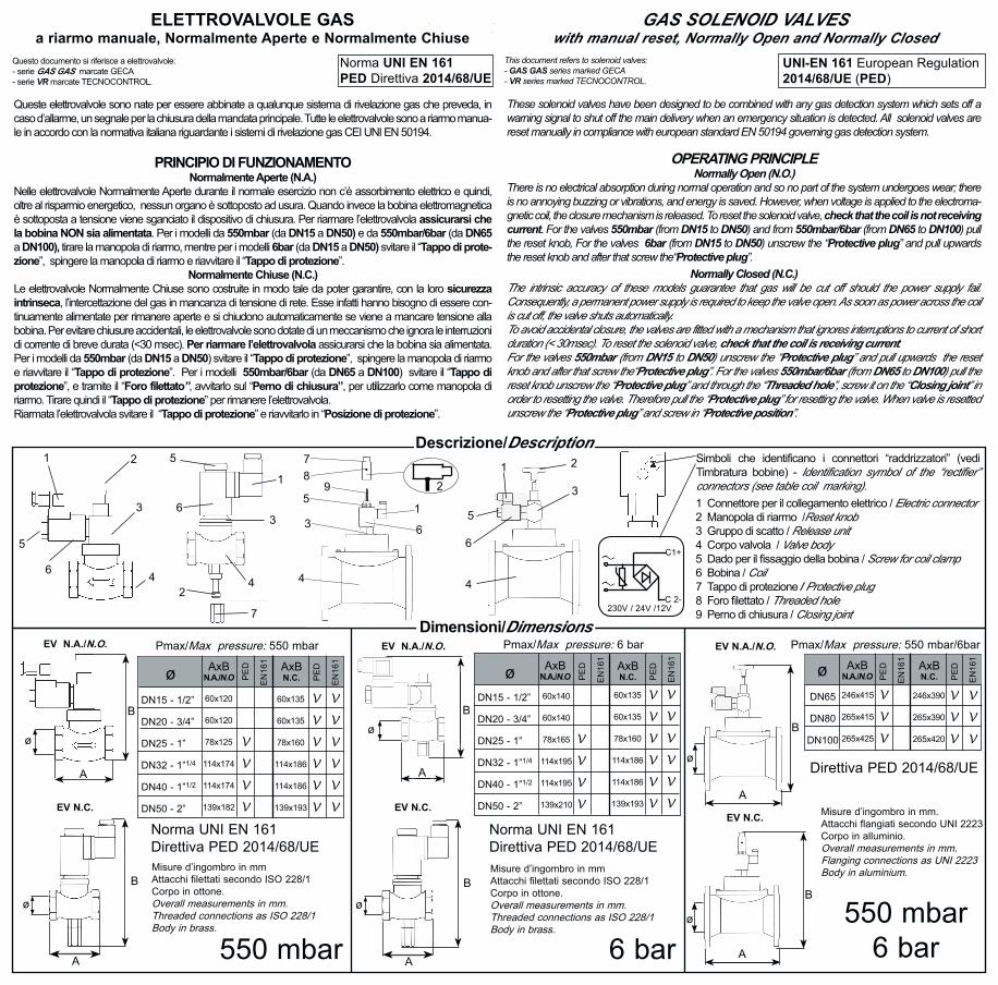
Simboli che identificano i connettori “raddrizzatori” (vedi Timbratura bobine) - Identification symbol of the “rectifier” connectors (see table coil marking).
1 2
3
4
5
6
EV N.C.
Queste elettrovalvole sono nate per essere abbinate a qualunque sistema di rivelazione gas che preveda, in caso d’allarme, un segnale per la chiusura della mandata principale. Tutte le elettrovalvole sono a riarmo manua-le in accordo con la normativa italiana riguardante i sistemi di rivelazione gas CEI UNI EN 50194.
PRINCIPIO DI FUNZIONAMENTONormalmente Aperte (N.A.)
Nelle elettrovalvole Normalmente Aperte durante il normale esercizio non c’è assorbimento elettrico e quindi, oltre al risparmio energetico, nessun organo è sottoposto ad usura. Quando invece la bobina elettromagnetica è sottoposta a tensione viene sganciato il dispositivo di chiusura. Per riarmare l’elettrovalvola assicurarsi che la bobina NON sia alimentata. Per i modelli da 550mbar (da DN15 a DN50) e da 550mbar/6bar (da DN65 a DN100), tirare la manopola di riarmo, mentre per i modelli 6bar (da DN15 a DN50) svitare il “Tappo di prote-zione”, spingere la manopola di riarmo e riavvitare il “Tappo di protezione”.
Normalmente Chiuse (N.C.)Le elettrovalvole Normalmente Chiuse sono costruite in modo tale da poter garantire, con la loro sicurezza intrinseca, l’intercettazione del gas in mancanza di tensione di rete. Esse infatti hanno bisogno di essere con-tinuamente alimentate per rimanere aperte e si chiudono automaticamente se viene a mancare tensione alla bobina. Per evitare chiusure accidentali, le elettrovalvole sono dotate di un meccanismo che ignora le interruzioni di corrente di breve durata (<30 msec). Per riarmare l’elettrovalvola assicurarsi che la bobina sia alimentata. Per i modelli da 550mbar (da DN15 a DN50) svitare il “Tappo di protezione”, spingere la manopola di riarmo e riavvitare il “Tappo di protezione”. Per i modelli 550mbar/6bar (da DN65 a DN100) svitare il “Tappo di protezione”, e tramite il “Foro filettato”, avvitarlo sul “Perno di chiusura”, per utilizzarlo come manopola di riarmo. Tirare quindi il “Tappo di protezione” per rimanere l’elettrovalvola. Riarmata l’elettrovalvola svitare il “Tappo di protezione” e riavvitarlo in “Posizione di protezione”.
These solenoid valves have been designed to be combined with any gas detection system which sets off a warning signal to shut off the main delivery when an emergency situation is detected. All solenoid valves are reset manually in compliance with european standard EN 50194 governing gas detection system.
OPERATING PRINCIPLENormally Open (N.O.)
There is no electrical absorption during normal operation and so no part of the system undergoes wear; there is no annoying buzzing or vibrations, and energy is saved. However, when voltage is applied to the electroma-gnetic coil, the closure mechanism is released. To reset the solenoid valve, check that the coil is not receiving current. For the valves 550mbar (from DN15 to DN50) and from 550mbar/6bar (from DN65 to DN100) pull the reset knob, For the valves 6bar (from DN15 to DN50) unscrew the “Protective plug” and pull upwards the reset knob and after that screw the“Protective plug”.
Normally Closed (N.C.)The intrinsic accuracy of these models guarantee that gas will be cut off should the power supply fail. Consequently, a permanent power supply is required to keep the valve open. As soon as power across the coil is cut off, the valve shuts automatically. To avoid accidental closure, the valves are fitted with a mechanism that ignores interruptions to current of short duration (< 30msec). To reset the solenoid valve, check that the coil is receiving current.For the valves 550mbar (from DN15 to DN50) unscrew the “Protective plug” and pull upwards the reset knob and after that screw the“Protective plug”. For the valves 550mbar/6bar (from DN65 to DN100) pull the reset knob unscrew the “Protective plug” and through the “Threaded hole”, screw it on the “Closing joint” in order to resetting the valve. Therefore pull the “Protective plug” for resetting the valve. When valve is resetted unscrew the “Protective plug” and screw in “Protective position”.
ø AxBN.A./N.O
AxBN.C.
Pmax/Max pressure: 550 mbar/6bar
Misure d’ingombro in mmAttacchi filettati secondo ISO 228/1Corpo in ottone.Overall measurements in mm.Threaded connections as ISO 228/1Body in brass.
Misure d’ingombro in mmAttacchi filettati secondo ISO 228/1Corpo in ottone.Overall measurements in mm.Threaded connections as ISO 228/1Body in brass.
Misure d’ingombro in mm.Attacchi flangiati secondo UNI 2223Corpo in alluminio.Overall measurements in mm.Flanging connections as UNI 2223Body in aluminium.
60x135
60x135
78x160
114x186
114x186
139x193
60x120
60x120
78x125
114x174
114x174
139x182
A
1 Connettore per il collegamento elettrico / Electric connector2 Manopola di riarmo /Reset knob3 Gruppo di scatto / Release unit4 Corpo valvola / Valve body5 Dado per il fissaggio della bobina / Screw for coil clamp6 Bobina / Coil7 Tappo di protezione / Protective plug8 Foro filettato / Threaded hole9 Perno di chiusura / Closing joint
EV N.A./N.O. EV N.A./N.O.
550 mbar 6 bar550 mbar
6 bar
6
1
2
3
4
5
7
ø
DN15 - 1/2”
DN20 - 3/4”
DN25 - 1”
DN32 - 1”1/4
DN40 - 1”1/2
DN50 - 2”
PE
D
EN
161
PE
D
EN
161
V
V
V
V
V
V
V
V
V
V
V
V
V
V
V
V
Pmax/Max pressure: 550 mbar
ø AxBN.A./N.O
AxBN.C.
60x135
60x135
78x160
114x186
114x186
139x193
60x140
60x140
78x165
114x195
114x195
139x210
DN15 - 1/2”
DN20 - 3/4”
DN25 - 1”
DN32 - 1”1/4
DN40 - 1”1/2
DN50 - 2”
PE
D
EN
161
PE
D
V
V
V
V
V
V
V
V
V
V
Pmax/Max pressure: 6 bar
EN
161
V
V
V
V
V
V
ø AxBN.A./N.O
AxBN.C.
246x390
265x390
265x420
246x415
265x415
265x425
DN65
DN80
DN100
PE
D
EN
161
PE
D
V
V
V
EN
161
A
B
Descrizione/Description
EV N.A./N.O.
4
51
63
78
29
Direttiva PED 2014/68/UE
EV N.C.
A
B
ø
1 2
3
46
5
BB
A
øø
GAS SOLENOID VALVESwith manual reset, Normally Open and Normally Closed
V
V
V
230V / 24V /12V
C1+
C 2-
V
V
V
Dimensioni/Dimensions
Questo documento si riferisce a elettrovalvole: - serie GAS GAS marcate GECA - serie VR marcate TECNOCONTROL.
A
EV N.C.
ø
A
ø
Norma UNI EN 161Direttiva PED 2014/68/UE
Norma UNI EN 161Direttiva PED 2014/68/UE
BB
ELETTROVALVOLE GASa riarmo manuale, Normalmente Aperte e Normalmente Chiuse
This document refers to solenoid valves:- GAS GAS series marked GECA - VR series marked TECNOCONTROL.
UNI-EN 161 European Regulation2014/68/UE (PED)
Norma UNI EN 161 PED Direttiva 2014/68/UE

Installazione e posizionamentoLeggere attentamente il foglietto istruzioni prima dell’uso. Questo dispositivo deve essere installato montando un filtro idoneo per gas (conforme alla norma UNI EN 161) a monte di esso, riferirsi inoltre alle leggi in vigore per una corretta installazione. L’elettrovalvola dev’essere installata con la freccia stampata sul corpo rivolta verso l’utenza a monte degli organi di regolazione, preferibil-mente all’esterno dell’ambiente in cui è presente l’utenza e al riparo dagli agenti atmosferici.
N.C.
N.A.N.O.
Timbrature bobine da 1/2” a 2”/Coil marking from 1/2” to 2”12 Vcc/Vdc
12Vdc 19W
12Vdc 6W
12Vac 17VA
12VRAC 12W
24Vdc 19W
24Vdc 9W
24Vac 17VA
24VRAC 5W
230Vac 17VA
230VRAC 9W
12Vca/Vac 24Vcc/Vdc 24Vca/Vac 230Vca/Vac-50/60Hz
: con queste bobine (12-24Vac), utilizzare il connettore Cod. 2.180.2430 che funge da “ritardatore” e “raddrizzatore”, presente nell’imballo.
Timbrature bobine da DN65 a DN100/Coil marking from DN65 to DN100
: a particular (12-24Vac) connector must be associated to these coils which acts as a “delayer” and “rectifier” included in the packaging: Cod. 2.180.2430
Installation and positioningRead instructions before use. This devise must be installed by fitting a suitable gas filter (according to UNI EN 161) upstream of it, also refer to the rules in force for proper installation. The solenoid valve must be positioned with the arrow stamped on the body turned towards the user appliance upstream of the regulation apparatus and preferably outside the measurement zone and repaired to the atmospheric agents.
Attacchi/Connection Posizione orizzontale/Horizontal position Posizione verticale/Vertical position Posizione capovolta/Overturned position
da 1/2” a DN100from 1/2” to DN100 NO
Cod
. 2.7
10.1
235
dis.
803
4033
L
MA
DE
IN IT
ALY
DIAGRAMMA DELLE PERDITE DI CARICOLOSS OF HEAD DIAGRAM
A B
: con queste bobine (230-110Vac-50/60Hz), utilizzare il connettore Cod. 2.180.2429 che funge da “ritardatore” e “raddrizzatore”, presente nell’imballo.
: a particular (230-110Vac-50/60Hz) connector must be associated to these coils which acts as a “delayer” and “rectifier” included in the packaging: Cod. 2.180.2429
A
B
A
B
FASEPHASE
NEUTRONEUTRAL
TERRAGROUND
A (12-24Vac) B (110/230Vac-50/60Hz)
FASEPHASE
NEUTRONEUTRAL
ManutenzioneSi consiglia di verificare periodicamente l’intervento dell’elettrovalvola. In caso di necessità, prima di effettuare qual-siasi operazione sull’elettrovalvola, accertarsi che all’interno della stessa non ci sia gas in pressione e che non sia alimentata elettricamente. Qualsiasi operazione di manutenzione dev’essere eseguita da personale qualificato.
MaintenanceThe solenoid valve’s intervention should be checked periodically. Should disassembly be necessary, make sure there is no gas under pressure inside the valve and that is not connected to the power supply before starting. All maintenance operations should be carried out by qualified personnel.
TERRAGROUND
+ TERRAGROUNDFASE
PHASE
NEUTRONEUTRAL
CARATTERISTICHE TECNICHE/TECHNICAL CHARACTERISTICS - Pressione max/Max pressure: 550mbar / 6bar (a seconda del modello/in according to the model)- Tempo di chiusura/Closing time: < 1 sec.- Potenza elettrica/Power capacity: tipo/type N.A./N.O. 12-24Vdc 19W 12-24-110-230Vac 15W - 17VA tipo/type N.C. 12-24Vdc 6W-9W-16W 12-24-110-230Vac 5W-7,5W-9W-12W-15W-16W
- Alimentazione elettrica/Power supply: 12Vdc, 12Vac, 24Vdc, 24Vac, 110Vac-50/60Hz, 230Vac-50/60Hz.- Attacchi/Connections: da 1/2”a 2” filettati secondo ISO 228/1, da DN65 a DN100 flangiati secondo UNI2223 from 1/2” of 2” threaded as ISO 228/1, from DN65 of DN100 flanging as UNI 2223- Grado di protezione elettrica/Level of electrical protection: IP65.- Classe /Class: A- Gruppo/Group: 2- Temperatura di lavoro/Operating temperature: -15°C..... +60°C.
La casa costruttrice riserva il diritto di apportare qualsiasi modifica, estetica o funzionale, senza preavviso alcuno ed in qualsiasi momento. The manufacturer firm reserves the right to make any aesthetic or functional modification to the without prior notice at any time.
Portata Q(Sm3/h)
110Vca/Vac-50/60Hz
110Vac 17VA
110VRAC 7,5W B
N.C.
N.A.N.O.
12 Vcc/Vdc
12Vdc 16W
12VRAC 17VA
12VRAC 16W 24Vdc 16W
24VRAC 17VA
24VRAC 16W
230VRAC 15W
230VRAC 15W
12Vca/Vac 24Vcc/Vdc 24Vca/Vac 230Vca/Vac-50/60Hz
A
110Vca/Vac-50/60Hz
A B 110VRAC 17VA B
A
A
A
B
GECA Srl Via E. Fermi, n°98 25064 Gussago (BS) Italy Tel. +39 030 3730218 www.gecasrl.it
Tecnocontrol Srl Via Miglioli, n°47 20090 Segrate (MI) Italy Tel. +39 02 26922890 www.tecnocontrol.it