
THOR 250 · Il produttore sarà libero di ... mo di leggere attentamente il presente manuale...
13
THOR 250 MANUALE D’USO E MANUTENZIONE USE AND MAINTENANCE MANUAL
Transcript of THOR 250 · Il produttore sarà libero di ... mo di leggere attentamente il presente manuale...

THOR 250MANUALE D’USO E MANUTENZIONE
USE AND MAINTENANCE MANUAL
OFF ON LED
TEST 1 START TEST 2
1
01 02
03OIL LEVEL
A
04
05 06
07 08
09 10
11 12
ITALIANO - MANUALE D’USO E MANUTENZIONE pagina 4• Utilizzare solo ricambi originali Polini Motori.• Il produttore sarà libero di apportare le modifiche che riterrà più opportune per migliorare le caratteristiche e prestazioni
dei prodotti.• Per le specifiche tecniche/istruzioni/optionals consultare il sito www.polinithor.com oppure www.polini.com
ENGLISH - USE AND MAINTENANCE MANUAL page 13• Only use Polini Motori original spare parts• The manufacturer has the right to make any modifications that can be useful to improve the features and performance of
the products.• For all the technical details/manuals/optional please check www.polinithor.com or www.polini.com
13 14
2 3
ITALIANO ITALIANO
15 16
17
928.230.0046x9 Mt.1
928.330.001928.220.002
143.230.00110x15 Mt.1
928.235.001ORD.MIN.5 PZ
928.340.007
928.220.001214.0106ORD.MIN.5 PZ
928.230.00216x23 Mt.1
928.235.002ORD.MIN.5 PZ
928.230.00316x23.5
928.235.003ORD.MIN.5 PZ
>100
60
272
8,5
6,5
31
30
32
355
204
50
225
11
11
A
B
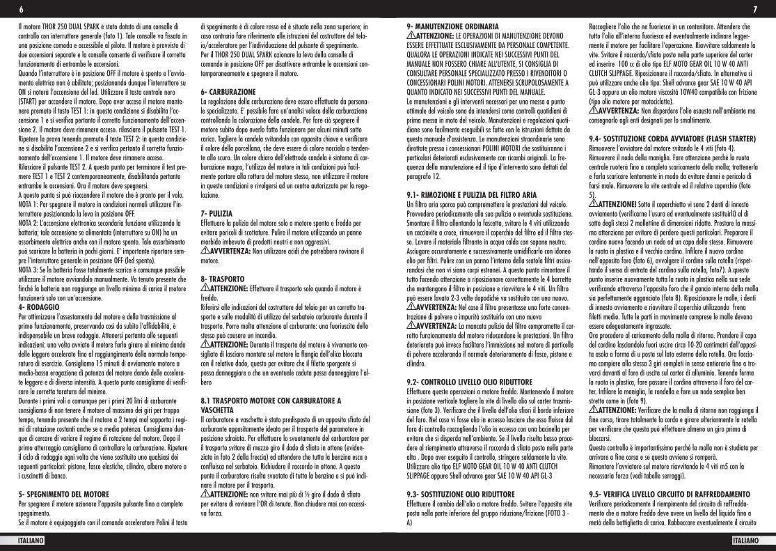
THOR 250 DUAL SPARK - WIRING DIAGRAM NEW VOLTAGE REGULATOR - NUOVO REGOLATORE DI TENSIONE
ROSSO - RED (E) 3
BIANCO - WHITE 1
BLU - BLUE 2
4
4 5
ITALIANO ITALIANO
PREMESSA Complimenti per aver acquistato un motore Thor Polini. Con questa scelta siete entrati a far parte di una distinta famiglia di possessori di un prodotto che vi darà grandi soddisfazioni. THOR è stato progettato in modo da garantire le migliori prestazioni possibili. Vi raccomandia-mo di leggere attentamente il presente manuale d’uso e manutenzio-ne prima di utilizzare il vostro nuovo motore. Questo libretto contie-ne informazioni importanti che vi aiuteranno a ottenere il massimo della soddisfazione che l’utilizzo del motore Thor può regalarvi. La perfetta messa a punto e la totale conoscenza del vostro motore assi-curano sicurezza e tranquillità durante il suo utilizzo.
INDICE 1- Avvertenze generali/Garanzia 2- Carburante 3- Messa in moto 4- Rodaggio 5- Spegnimento del motore 6- Controllo carburazione 7- Pulizia 8- Trasporto 9- Manutenzione ordinaria 10- Comportamento da tenere durante le fasi di volo 11- Installazione del motore sul telaio 12- Tabelle manutenzione 13- Diagnosi difetti
1- AVVERTENZE GENERALI La Polini ed il distributore declinano ogni responsabilità diretta o indi-retta legata all’uso del proprio motore, soprattutto nel caso in cui il motore venga modificato o manomesso da terzi. La Polini non si assume la responsabilità di danni causati dalla scarsa manutenzione o dall’errato montaggio, escludendo la sostituzione dei pezzi dalla garanzia. Eventuali modifiche tecniche potranno essere apportate dall’acquirente, che si assume tutta la responsabilità di eventuali danni; i pezzi di ricambio a scopo di modifica non sono coperti dalla garanzia. Si avverte che ogni modifica al motore apportata dall’ac-quirente o la rimozione di parti originali possono rendere il motore pericoloso! L’utente è invitato a rispettare ed attenersi a quanto indicato e consi-gliato nel manuale d’uso e manutenzione per l’incolumità propria e di terzi. L’utilizzo che viene fatto di questo motore è molto rischioso, quindi bisogna avere la massima attenzione prima, durante e dopo il volo, per non incorrere in incidenti molto gravi. A causa dei rischi insiti nell’uso del motore, e quindi del volo, la Polini non concede nessuna garanzia contro incidenti, rotture, ferite o morte. Volare con il paramotore richiede sempre la massima attenzione. Siate consape-voli che volate a vostro rischio. Prima di ogni utilizzo controllate le buone condizioni del motore. Questo motore non è coperto da alcuna assicurazione di responsabilità. L’uso dello stesso determina automati-camente l’assunzione di tutti i rischi inerenti lo sport del volo e la personale responsabilità verso danni propri o a terzi, incidenti, ferite
o morte, derivanti dall’uso di questo prodotto. Si invita pertanto a leggere attentamente le istruzioni contenute in questo manuale, in quanto utili per una maggiore conoscenza del prodotto e padronanza dello stesso e dunque utili a prevenire e misurare eventuali rischi.
GARANZIA Tutti i motori Polini sono costruiti con materiale di qualità per cui si garantisce che il prodotto acquistato è privo di difetti, a condizione che l’acquirente acquisti il prodotto da un concessionario autorizzato Polini.DURATA La garanzia ha una durata di 12 mesi decorrenti dalla data di vendi-ta all’utente finale. E’ necessario attivare la garanzia con l’apposito modulo (vedi ultima pagina) e conservare lo scontrino fiscale o la fattura. COPERTURA La presente garanzia copre i danni del motore causati da componenti difettosi per forma o materiale, per progettazione non conforme all’utilizzo indicato, assemblaggio non corretto da parte della casa costruttrice. La Garanzia comprende i soli pezzi di ricambio. Sono esclusi dalla garanzia i costi di trasporto, che saranno a carico dell’u-tente. Sono esclusi dalla garanzia i danni derivanti da: - modifiche al motore non approvate dalla Polini - normale logorio o usura dei componenti - negligenza, mancanza di manutenzione, incidenti, installazione o manutenzione non corrette; - cadute accidentali o caduta del motore o dei suoi componenti; - un utilizzo improprio o dal maltrattamento del motore; - uso di accessori o componenti non indicati nell’utilizzo del motore - surriscaldamento o fermo del motore a causa dell’uso prolungato, oltre il termine consigliato dalla Polini; - mancata o irregolare manutenzione del motore come indicato dalla Polini, uso di carburanti o lubrificanti non adatti, presenza di sporcizia o di corpi estranei nel motore, anche aspirati; - affaticamento del motore per utilizzo di carichi eccessivi; - uso di eliche non certificate Polini- deterioramento del motore o di parte di esso per custodia in luoghi non idonei; - assemblaggio non corretto del motore, compreso l’uso di componenti non originali Polini e comunque di proprietà di terzi; - danni al motore derivanti da oggetti esterni; - interventi di manutenzione da parte di soggetti diversi dalla Polini o da soggetti non autorizzati dalla Polini; - utilizzo del motore per competizioni. - utilizzo del motore senza elica.
Adempimenti da parte dell’utente finale Ogni reclamo dovrà essere effettuato consegnando il prodotto da ispezionare ad un concessionario Polini autorizzato. L’acquirente dovrà fornire la copia della “prova di acquisto” in originale o del tagliando di garanzia regolarmente vidimato dalla Polini o dal distri-butore. Per conservare la validità della garanzia il cliente deve effet-tuare le manutenzioni periodiche previste dal manuale di uso e manutenzione.
ITALIANO Limitazioni di responsabilità Conformemente a quanto stipulato nella presente garanzia, gli obbli-ghi della Polini saranno limitati alla riparazione del componente difettoso o, a discrezione, alla sostituzione di uno o più componenti, secondo quanto sarà ritenuto necessario per porre rimedio ad ogni malfunzionamento dovuto ai difetti di materiale o di manodopera coperti dalla garanzia. Alcuna responsabilità può essere imputata alla Polini o al distributore del motore per ogni problema o danno recato a persone/cose/animali riscontrato durante tutta la vita del motore. Ricordiamo che questo prodotto non è certificato ed è dedicato a velivoli sperimentali e che in qualsiasi momento può rompersi o smettere di funzionare. Pertanto non sono coperti né da garanzia né da risarcimento i danni causati: - a persone/animali/cose causati dall’utilizzo generico del motore. - a persone/animali/cose causati da una collisione con l’elica o una qualsiasi parte staccatasi dal motore. - al telaio, componenti del velivolo e/o all’elica causati dalla collisione con una qualsiasi parte proveniente dal motore. - spese di recupero, di spedizione, telefoniche o di noleggio di qualsiasi tipo, inconvenienti o perdite di tempo, o altri danni indiretti.
PERICOLO! Questo motore, non certificato, può spegnersi di colpo. L’interruzione del motore può provocare atterraggi di fortuna che possono produrre ferite o portare alla morte. Il velivolo spinto da questo motore dovrebbe volare soltanto negli spazi aperti e negli orari di luce. L’acquirente si assume tutto il rischio per l’uso ed è con-sapevole che durante il suo utilizzo questo motore si potrebbe spe-gnere di colpo. Questo prodotto non è coperto da responsabilità civile prodotti. Chi vola con questo motore o semplicemente lo accende si assume tutti i rischi inerenti lo sport del volo a motore ed ogni responsabilità per danni a cose e a persone, o decesso causato dall’u-so di questo prodotto. In considerazione di ciò, non sono coperti da garanzia i danni causati dall’installazione del motore su apparecchi che richiedono motori certificati. /su apparecchi ai quali non è ido-neo/ su apparecchi che richiedono diverso tipo di motore. L’odierno venditore pertanto non risponderà di danni causati all’utilizzatore od a terzi.
2- CARBURANTE Il Thor è un motore a 2 tempi che necessita di una miscela di benzina e olio. Utilizzare solo benzina verde acquistata al distributore con un numero di ottani pari a 98 di buona qualità . Addizionare la benzina con olio sintetico di buona qualità al 2%. E’ possibile utilizzare una miscela con olio al 1,5% utilizzando i seguenti oli: MOTUL 800 – VALVOLINE RACING 2T FULL SYNTHETIC SAE 50 - BARDAL KXT - ELF 976 – ELF 909. Non conservare a lungo la benzina in contenitori perché subisce un deterioramento della qualità, utilizzare contenitori metallici certificati per il trasporto carburanti. Miscelare la benzina con l’olio solo al momento dell’utilizzo.
AVVERTENZA: il tipo di incrostazioni carboniose depositate sulla testa, sulla candela e sullo scarico del cilindro sono informazioni che indicano il tipo di miscelazione del vostro motore. Si rammenta
che una combustione troppo ricca d’olio non allunga la durata del motore.
ATTENZIONE: la benzina è estremamente infiammabile ed esplosiva. Eseguire queste operazioni in un luogo ben ventilato e a motore spento. Non fumare, non provocare scintille o fiamme nell’a-rea in cui la benzina viene conservata e dove avviene il rifornimento.
ATTENZIONE! Solo per i clienti Americani. Il numero di ottani Europeo non equivale a quello Americano:es. EU 95 OTTANI = US 91 OTTANI / EU 98 OTTANI = US 93 OCTANE Per i motori Thor usare una benzina con un alto numero di ottani (non meno di US 91).
3- MESSA IN MOTO Avviare il motore solo dopo essersi accertati che sia tutto in ordine e perfettamente funzionante, che non ci siano persone, cose o animali nei dintorni Verificare inoltre il corretto serraggio della bulloneria e controllare l’impianto di alimentazione.
3.1- AVVIAMENTO MANUALERiempire il circuito carburante, fare arrivare la benzina fino al foro di ingresso del carburatore e successivamente pompare per tre volte (utilizzando la pompa manuale Polini cod. 316.0106) per riempire la vaschetta. Per avviare il motore tirare verso l’alto la leva nera starter posizionata nella parte superiore del corpo carburatore. Azionare l’avviatore senza accelerare fino a che il motore non parte. Una volta acceso spegnere il motore,disinserire lo starter abbassandolo e riav-viare il motore questa volta se necessario accelerando lievemente. Per la vostra sicurezza avviate il vostro motore solo dopo esservi COMPLETAMENTE imbragati!
3.2- AVVIAMENTO ELETTRICO Eseguire il riempimento del circuito carburante come specificato nel paragrafo precedente.Se si dispone del comando gas Polini premere contemporaneamente i due tasti di colore nero accelerando lievemente fino all’accensione del motore. Se necessario azionare lo starter per facilitare l’avvia-mento a freddo.Se non si dispone del comando acceleratore Polini fare riferimento alle istruzioni del costruttore del velivolo per determinare la posizio-ne dei pulsanti di avviamento e di spegnimento.
ATTENZIONE: Durante tutte le fasi tenere sempre in mano l’in-terruttore di spegnimento e tenersi pronti ad azionarlo in qualsiasi caso di anomalia. Nel qual caso tenerlo premuto fino a completo spe-gnimento del motore. Una volta avviato il motore consigliamo di fare un test di corretto funzionamento del pulsante di spegnimento. Dopo il controllo riavviare il motore senza accelerare e senza l’utilizzo dello starter. A questo punto lasciar girare al minimo il motore dando delle leggere accelerate fino a portare il motore in temperatura.
3.3- AVVIAMENTO ELETTRICO DUAL SPARK E TEST DELLE ACCENSIONI Eseguire il riempimento del circuito carburante come specificato nel paragrafo 3.1
6 7
ITALIANO ITALIANO
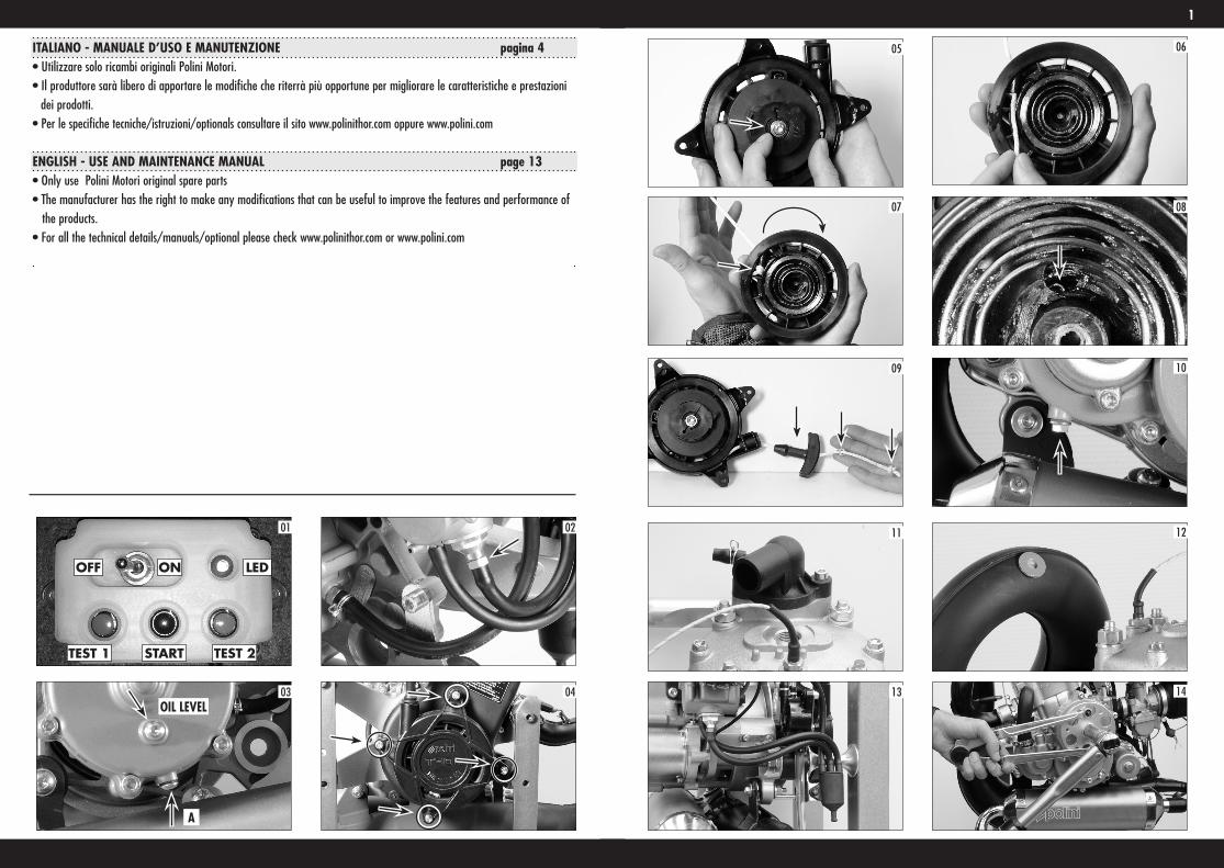
Il motore THOR 250 DUAL SPARK è stato dotato di una consolle di controllo con interruttore generale (foto 1). Tale consolle va fissata in una posizione comoda e accessibile al pilota. Il motore è provvisto di due accensioni separate e la consolle consente di verificare il corretto funzionamento di entrambe le accensioni.Quando l’interruttore è in posizione OFF il motore è spento e l’avvia-mento elettrico non è abilitato; posizionando dunque l’interruttore su ON si noterà l’accensione del led. Utilizzare il tasto centrale nero (START) per accendere il motore. Dopo aver acceso il motore mante-nere premuto il tasto TEST 1: in questa condizione si disabilita l’ac-censione 1 e si verifica pertanto il corretto funzionamento dell’accen-sione 2. Il motore deve rimanere acceso. rilasciare il pulsante TEST 1.Ripetere la prova tenendo premuto il tasto TEST 2: in questa condizio-ne si disabilita l’accensione 2 e si verifica pertanto il corretto funzio-namento dell’accensione 1. Il motore deve rimanere acceso. Rilasciare il pulsante TEST 2. A questo punto per terminare il test pre-mere TEST 1 e TEST 2 contemporaneamente, disabilitando pertanto entrambe le accensioni. Ora il motore deve spegnersi.A questo punto si può riaccendere il motore che è pronto per il volo.NOTA 1: Per spegnere il motore in condizioni normali utilizzare l’in-terruttore posizionando la leva in posizione OFF.NOTA 2: L’accensione elettronica secondaria funziona utilizzando la batteria; tale accensione se alimentata (interruttore su ON) ha un assorbimento elettrico anche con il motore spento. Tale assorbimento può scaricare la batteria in pochi giorni. E‘ importante riportare sem-pre l’interruttore generale in posizione OFF (led spento).NOTA 3: Se la batteria fosse totalmente scarica è comunque possibile utilizzare il motore avviandolo manualmente. Va tenuto presente che finché la batteria non raggiunge un livello minimo di carica il motore funzionerà solo con un’accensione.4- RODAGGIO Per ottimizzare l’assestamento del motore e della trasmissione al primo funzionamento, preservando così da subito l’affidabilità, è indispensabile un breve rodaggio. Attenersi pertanto alle seguenti indicazioni: una volta avviato il motore farlo girare al minimo dando delle leggere accelerate fino al raggiungimento della normale tempe-ratura di esercizio. Consigliamo 15 minuti di avviamento motore a medio-bassa erogazione di potenza del motore dando delle accelera-te leggere e di diversa intensità. A questo punto consigliamo di verifi-care la corretta taratura del minimo. Durante i primi voli o comunque per i primi 20 litri di carburante consigliamo di non tenere il motore al massimo dei giri per troppo tempo, tenendo presente che il motore a 2 tempi mal sopporta i regi-mi di rotazione costanti anche se a media potenza. Consigliamo dun-que di cercare di variare il regime di rotazione del motore. Dopo il primo atterraggio consigliamo di controllare la carburazione. Ripetere il ciclo di rodaggio ogni volta che viene sostituito uno qualsiasi dei seguenti particolari: pistone, fasce elastiche, cilindro, albero motore o i cuscinetti di banco.
5- SPEGNIMENTO DEL MOTORE Per spegnere il motore azionare l’apposito pulsante fino a completo spegnimento.Se il motore è equipaggiato con il comando acceleratore Polini il tasto
di spegnimento è di colore rosso ed è situato nella zona superiore; in caso contrario fare riferimento alle istruzioni del costruttore del tela-io/acceleratore per l’individuazione del pulsante di spegnimento.Per il THOR 250 DUAL SPARK azionare la leva della consolle di comando in posizione OFF per disattivare entrambe le accensioni con-temporaneamente e spegnere il motore.
6- CARBURAZIONE La regolazione della carburazione deve essere effettuata da persona-le specializzato. E’ possibile fare un’analisi veloce della carburazione controllando la colorazione della candela. Per fare ciò spegnere il motore subito dopo averlo fatto funzionare per alcuni minuti sotto carico. Togliere la candela svitandola con apposita chiave e verificare il colore della porcellana, che deve essere di colore nocciola o tenden-te allo scuro. Un colore chiaro dell’elettrodo candela è sintomo di car-burazione magra, l’utilizzo del motore in tali condizioni può facil-mente portare alla rottura del motore stesso, non utilizzare il motore in queste condizioni e rivolgersi ad un centro autorizzato per la rego-lazione.
7- PULIZIA Effettuare la pulizia del motore solo a motore spento e freddo per evitare pericoli di scottature. Pulire il motore utilizzando un panno morbido imbevuto di prodotti neutri e non aggressivi.
AVVERTENZA: Non utilizzare acidi che potrebbero rovinare il motore.
8- TRASPORTO ATTENZIONE: Effettuare il trasporto solo quando il motore è
freddo. Riferirsi alle indicazioni del costruttore del telaio per un corretto tra-sporto e sulle modalità di utilizzo del serbatoio carburante durante il trasporto. Porre molta attenzione al carburante: una fuoriuscita dello stesso può causare un incendio.
ATTENZIONE: Durante il trasporto del motore è vivamente con-sigliato di lasciare montata sul motore la flangia dell’elica bloccata con il relativo dado, questo per evitare che il filetto sporgente si possa danneggiare o che un eventuale caduta possa danneggiare l’al-bero
8.1 TRASPORTO MOTORE CON CARBURATORE A VASCHETTA Il carburatore a vaschetta è stato predisposto di un apposito sfiato del carburante appositamente ideato per il trasporto del paramotore in posizione sdraiata. Per effettuare lo svuotamento del carburatore per il trasporto svitare di mezzo giro il dado di sfiato in ottone (eviden-ziato in foto 2 dalla freccia) ed attendere che tutta la benzina esca e confluisca nel serbatoio. Richiudere il raccordo in ottone. A questo punto il carburatore risulta svuotato di tutta la benzina e si può incli-nare il motore per il trasporto.
ATTENZIONE: non svitare mai più di ½ giro il dado di sfiato per evitare di rovinare l’OR di tenuta. Non chiudere mai con eccessi-va forza.
9- MANUTENZIONE ORDINARIA ATTENZIONE: LE OPERAZIONI DI MANUTENZIONE DEVONO
ESSERE EFFETTUATE ESCLUSIVAMENTE DA PERSONALE COMPETENTE. QUALORA LE OPERAZIONI INDICATE NEI SUCCESSIVI PUNTI DEL MANUALE NON FOSSERO CHIARE ALL’UTENTE, SI CONSIGLIA DI CONSULTARE PERSONALE SPECIALIZZATO PRESSO I RIVENDITORI O CONCESSIONARI POLINI MOTORI. ATTENERSI SCRUPOLOSAMENTE A QUANTO INDICATO NEI SUCCESSIVI PUNTI DEL MANUALE. Le manutenzioni e gli interventi necessari per una messa a punto ottimale del veicolo sono da intendersi come controlli quotidiani di prima messa in moto del veicolo. Manutenzioni e regolazioni quoti-diane sono facilmente eseguibili se fatte con le istruzioni dettate da questo manuale d’assistenza. Le manutenzioni straordinarie sono dirottate presso i concessionari POLINI MOTORI che sostituiranno i particolari deteriorati esclusivamente con ricambi originali. La fre-quenza della manutenzione ed il tipo d’intervento sono dettati dal paragrafo 12.
9.1- RIMOZIONE E PULIZIA DEL FILTRO ARIA Un filtro aria sporco può compromettere le prestazioni del veicolo. Provvedere periodicamente alla sua pulizia o eventuale sostituzione. Smontare il filtro allentando la fascetta, svitare le 4 viti utilizzando un cacciavite a croce, rimuovere il coperchio del filtro ed il filtro stes-so. Lavare il materiale filtrante in acqua calda con sapone neutro. Asciugare accuratamente e successivamente umidificarlo con idoneo olio per filtri. Pulire con un panno l’interno della scatola filtri assicu-randosi che non vi siano corpi estranei. A questo punto rimontare il tutto facendo attenzione a riposizionare correttamente le 4 barrette che mantengono il filtro in posizione e riavvitare le 4 viti. Un filtro può essere lavato 2-3 volte dopodiché va sostituito con uno nuovo.
AVVERTENZA: Nel caso il filtro presentasse una forte concen-trazione di polvere o impurità sostituirlo con uno nuovo
AVVERTENZA: La mancata pulizia del filtro compromette il cor-retto funzionamento del motore riducendone le prestazioni. Un filtro deteriorato può invece facilitare l’immissione nel motore di particelle di polvere accelerando il normale deterioramento di fasce, pistone e cilindro.
9.2- CONTROLLO LIVELLO OLIO RIDUTTORE Effettuare queste operazioni a motore freddo. Mantenendo il motore in posizione verticale togliere la vite di livello olio sul carter trasmis-sione (foto 3). Verificare che il livello dell’olio sfiori il bordo inferiore del foro. Nel caso vi fosse olio in eccesso lasciare che esso fluisca dal foro di controllo raccogliendo l’olio in eccesso con una bacinella per evitare che si disperda nell’ambiente. Se il livello risulta basso proce-dere al riempimento attraverso il raccordo di sfiato posto nella parte alta . Dopo aver eseguito il controllo, stringere saldamente la vite. Utilizzare olio tipo ELF MOTO GEAR OIL 10 W 40 ANTI CLUTCH SLIPPAGE oppure Shell advance gear SAE 10 W 40 API GL-3
9.3- SOSTITUZIONE OLIO RIDUTTOREEffettuare il cambio dell’olio a motore freddo. Svitare l’apposita vite posta nella parte inferiore del gruppo riduzione/frizione (FOTO 3 - A)
Raccogliere l’olio che ne fuoriesce in un contenitore. Attendere che tutto l’olio all’interno fuoriesca ed eventualmente inclinare legger-mente il motore per facilitare l’operazione. Riavvitare saldamente la vite. Svitare il raccordo/sfiato posto nella parte superiore del carter ed inserire 100 cc di olio tipo ELF MOTO GEAR OIL 10 W 40 ANTI CLUTCH SLIPPAGE. Riposizionare il raccordo/sfiato. In alternativa si può utilizzare anche olio tipo: Shell advance gear SAE 10 W 40 API GL-3 oppure un olio motore viscosità 10W40 compatibile con frizione (tipo olio motore per motociclette).
AVVERTENZA: Non disperdere l’olio esausto nell’ambiente ma consegnarlo agli enti designati per lo smaltimento.
9.4- SOSTITUZIONE CORDA AVVIATORE (FLASH STARTER) Rimuovere l’avviatore dal motore svitando le 4 viti (foto 4). Rimuovere il nodo della maniglia. Fare attenzione perché la ruota centrale ruoterà fino a completo scaricamento della molla; trattenerla e farla scaricare lentamente in modo da evitare danni e pericolo di farsi male. Rimuovere la vite centrale ed il relativo coperchio (foto 5).
ATTENZIONE! Sotto il coperchietto vi sono 2 denti di innesto avviamento (verificarne l’usura ed eventualmente sostituirli) al di sotto degli stessi 2 mollettine di dimensioni ridotte. Prestare la massi-ma attenzione per evitare di perdere questi particolari. Preparare il cordino nuovo facendo un nodo ad un capo dello stesso. Rimuovere la ruota in plastica e il vecchio cordino. Infilare il nuovo cordino nell’apposito foro (foto 6), avvolgere il cordino sulla rotella (rispet-tando il senso di entrata del cordino sulla rotella, foto7). A questo punto inserire nuovamente tutta la ruota in plastica nella sua sede verificando attraverso l’apposito foro che il gancio interno della molla sia perfettamente agganciato (foto 8). Riposizionare le molle, i denti di innesto avviamento e riavvitare il coperchio utilizzando frena filetti medio. Tutte le parti in movimento comprese le molle devono essere adeguatamente ingrassate.Ora procedere al caricamento della molla di ritorno. Prendere il capo del cordino lasciandolo fuori uscire circa 10-20 centimetri dall‘apposi-ta asola a forma di u posta sul lato esterno della rotella. Ora faccia-mo compiere alla stessa 3 giri completi in senso antiorario fino a tro-varci davanti al foro di uscita sul carter di alluminio. Tenendo ferma la ruota in plastica, fare passare il cordino attraverso il foro del car-ter. Infilare la maniglia, la rondella e fare un nodo semplice ben stretto come in (foto 9).
ATTENZIONE: Verificare che la molla di ritorno non raggiunga il fine corsa, tirare totalmente la corda e girare ulteriormente la rotella per verificare che questa può effettuare almeno un giro prima di bloccarsi.Questo controllo è importantissimo perché la molla non è studiata per arrivare a fine corsa e se questo avviene si romperà.Rimontare l’avviatore sul motore riavvitando le 4 viti m5 con la necessaria forza (vedi tabelle serraggi).
9.5- VERIFICA LIVELLO CIRCUITO DI RAFFREDDAMENTOVerificare periodicamente il riempimento del circuito di raffredda-mento che a motore freddo deve avere un livello del liquido fino a metà della bottiglietta di carica. Rabboccare eventualmente il circuito
8 9
ITALIANO ITALIANO
utilizzando del liquido di raffreddamento specifico per radiatori in alluminio.
ATTENZIONE: Non aprire mai il tappo con il motore caldo, peri-colo di ustioni.
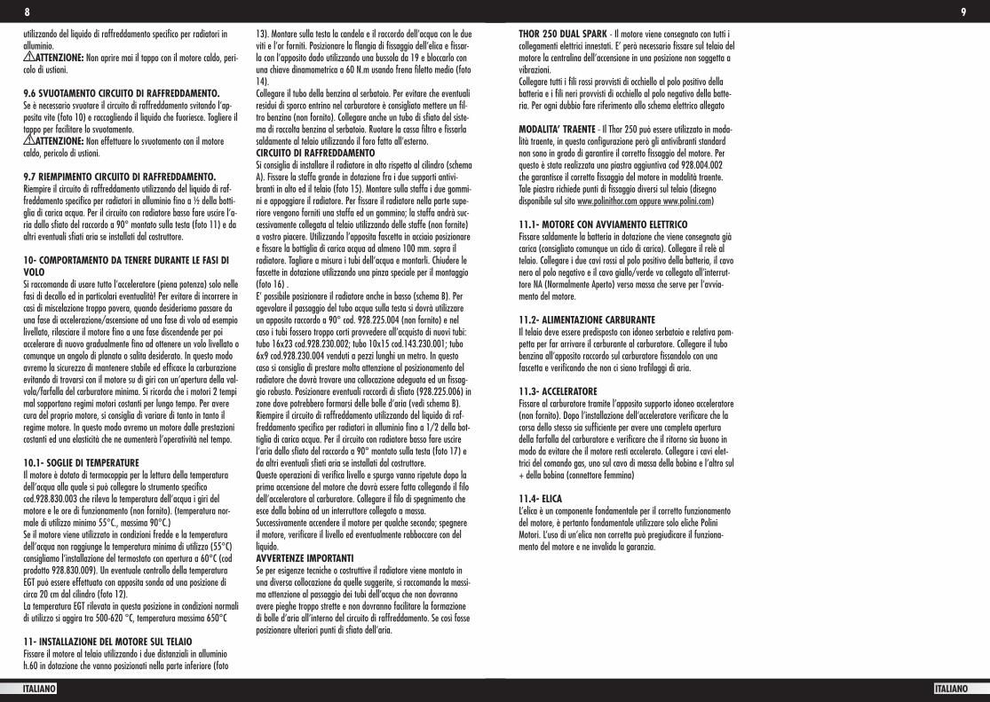
9.6 SVUOTAMENTO CIRCUITO DI RAFFREDDAMENTO.Se è necessario svuotare il circuito di raffreddamento svitando l’ap-posita vite (foto 10) e raccogliendo il liquido che fuoriesce. Togliere il tappo per facilitare lo svuotamento.
ATTENZIONE: Non effettuare lo svuotamento con il motore caldo, pericolo di ustioni.
9.7 RIEMPIMENTO CIRCUITO DI RAFFREDDAMENTO.Riempire il circuito di raffreddamento utilizzando del liquido di raf-freddamento specifico per radiatori in alluminio fino a ½ della botti-glia di carica acqua. Per il circuito con radiatore basso fare uscire l’a-ria dallo sfiato del raccordo a 90° montato sulla testa (foto 11) e da altri eventuali sfiati aria se installati dal costruttore.
10- COMPORTAMENTO DA TENERE DURANTE LE FASI DI VOLO Si raccomanda di usare tutto l’acceleratore (piena potenza) solo nelle fasi di decollo ed in particolari eventualità! Per evitare di incorrere in casi di miscelazione troppo povera, quando desideriamo passare da una fase di accelerazione/ascensione ad una fase di volo ad esempio livellato, rilasciare il motore fino a una fase discendende per poi accelerare di nuovo gradualmente fino ad ottenere un volo livellato o comunque un angolo di planata o salita desiderato. In questo modo avremo la sicurezza di mantenere stabile ed efficace la carburazione evitando di trovarsi con il motore su di giri con un’apertura della val-vola/farfalla del carburatore minima. Si ricorda che i motori 2 tempi mal sopportano regimi motori costanti per lungo tempo. Per avere cura del proprio motore, si consiglia di variare di tanto in tanto il regime motore. In questo modo avremo un motore dalle prestazioni costanti ed una elasticità che ne aumenterà l’operatività nel tempo.
10.1- SOGLIE DI TEMPERATURE Il motore è dotato di termocoppia per la lettura della temperatura dell’acqua alla quale si può collegare lo strumento specifico cod.928.830.003 che rileva la temperatura dell’acqua i giri del motore e le ore di funzionamento (non fornito). (temperatura nor-male di utilizzo minimo 55°C., massima 90°C.)Se il motore viene utilizzato in condizioni fredde e la temperatura dell’acqua non raggiunge la temperatura minima di utilizzo (55°C) consigliamo l’installazione del termostato con apertura a 60°C (cod prodotto 928.830.009). Un eventuale controllo della temperatura EGT può essere effettuato con apposita sonda ad una posizione di circa 20 cm dal cilindro (foto 12).La temperatura EGT rilevata in questa posizione in condizioni normali di utilizzo si aggira tra 500-620 °C, temperatura massima 650°C
11- INSTALLAZIONE DEL MOTORE SUL TELAIOFissare il motore al telaio utilizzando i due distanziali in alluminio h.60 in dotazione che vanno posizionati nella parte inferiore (foto
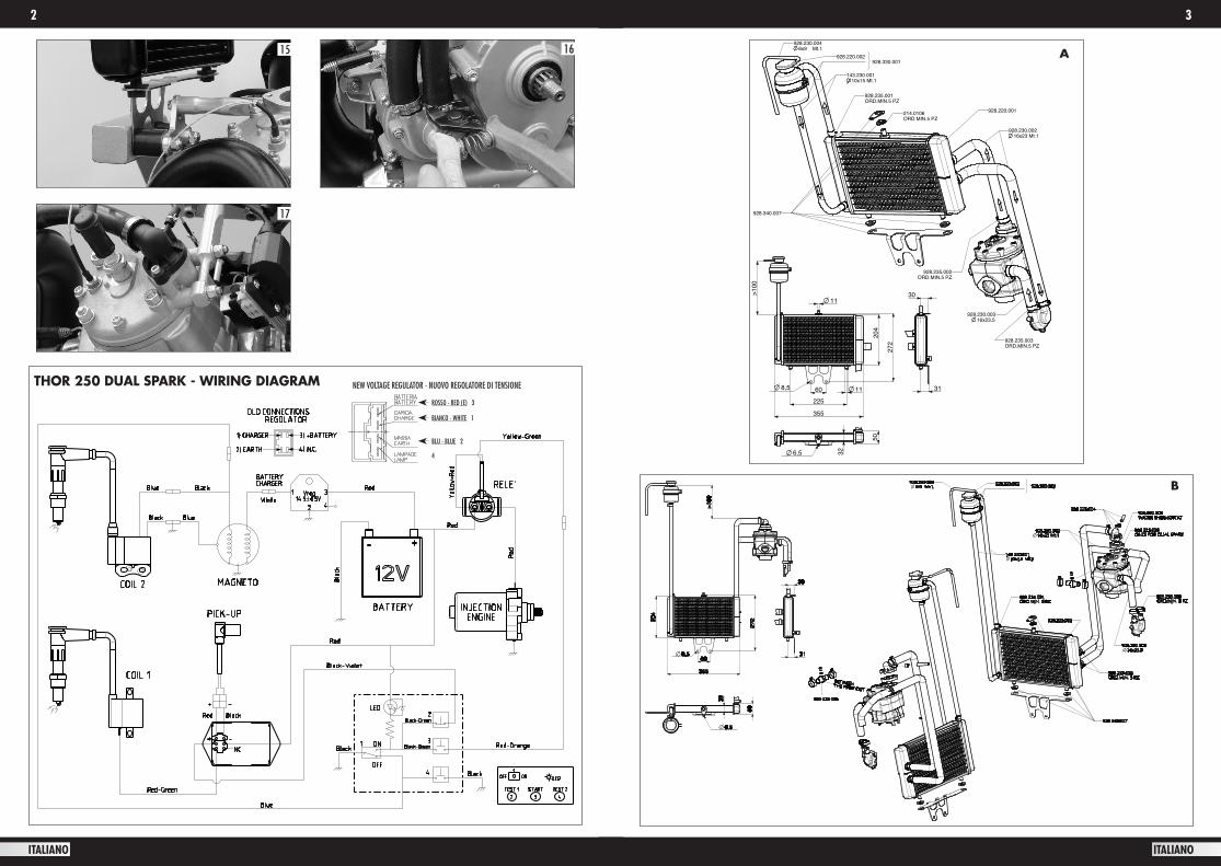
13). Montare sulla testa la candela e il raccordo dell’acqua con le due viti e l’or forniti. Posizionare la flangia di fissaggio dell’elica e fissar-la con l’apposito dado utilizzando una bussola da 19 e bloccarlo con una chiave dinamometrica a 60 N.m usando frena filetto medio (foto 14).Collegare il tubo della benzina al serbatoio. Per evitare che eventuali residui di sporco entrino nel carburatore è consigliato mettere un fil-tro benzina (non fornito). Collegare anche un tubo di sfiato del siste-ma di raccolta benzina al serbatoio. Ruotare la cassa filtro e fissarla saldamente al telaio utilizzando il foro fatto all’esterno.CIRCUITO DI RAFFREDDAMENTOSi consiglia di installare il radiatore in alto rispetto al cilindro (schema A). Fissare la staffa grande in dotazione fra i due supporti antivi-branti in alto ed il telaio (foto 15). Montare sulla staffa i due gommi-ni e appoggiare il radiatore. Per fissare il radiatore nella parte supe-riore vengono forniti una staffa ed un gommino; la staffa andrà suc-cessivamente collegata al telaio utilizzando delle staffe (non fornite) a vostro piacere. Utilizzando l’apposita fascetta in acciaio posizionare e fissare la bottiglia di carica acqua ad almeno 100 mm. sopra il radiatore. Tagliare a misura i tubi dell’acqua e montarli. Chiudere le fascette in dotazione utilizzando una pinza speciale per il montaggio (foto 16) .E’ possibile posizionare il radiatore anche in basso (schema B). Per agevolare il passaggio del tubo acqua sulla testa si dovrà utilizzare un apposito raccordo a 90° cod. 928.225.004 (non fornito) e nel caso i tubi fossero troppo corti provvedere all’acquisto di nuovi tubi: tubo 16x23 cod.928.230.002; tubo 10x15 cod.143.230.001; tubo 6x9 cod.928.230.004 venduti a pezzi lunghi un metro. In questo caso si consiglia di prestare molta attenzione al posizionamento del radiatore che dovrà trovare una collocazione adeguata ed un fissag-gio robusto. Posizionare eventuali raccordi di sfiato (928.225.006) in zone dove potrebbero formarsi delle bolle d’aria (vedi schema B).Riempire il circuito di raffreddamento utilizzando del liquido di raf-freddamento specifico per radiatori in alluminio fino a 1/2 della bot-tiglia di carica acqua. Per il circuito con radiatore basso fare uscire l’aria dallo sfiato del raccordo a 90° montato sulla testa (foto 17) e da altri eventuali sfiati aria se installati dal costruttore.Queste operazioni di verifica livello e spurgo vanno ripetute dopo la prima accensione del motore che dovrà essere fatta collegando il filo dell’acceleratore al carburatore. Collegare il filo di spegnimento che esce dalla bobina ad un interruttore collegato a massa. Successivamente accendere il motore per qualche secondo; spegnere il motore, verificare il livello ed eventualmente rabboccare con del liquido.AVVERTENZE IMPORTANTISe per esigenze tecniche o costruttive il radiatore viene montato in una diversa collocazione da quelle suggerite, si raccomanda la massi-ma attenzione al passaggio dei tubi dell’acqua che non dovranno avere pieghe troppo strette e non dovranno facilitare la formazione di bolle d’aria all’interno del circuito di raffreddamento. Se così fosse posizionare ulteriori punti di sfiato dell’aria.
THOR 250 DUAL SPARK - Il motore viene consegnato con tutti i collegamenti elettrici innestati. E’ però necessario fissare sul telaio del motore la centralina dell’accensione in una posizione non soggetta a vibrazioni.Collegare tutti i fili rossi provvisti di occhiello al polo positivo della batteria e i fili neri provvisti di occhiello al polo negativo della batte-ria. Per ogni dubbio fare riferimento allo schema elettrico allegato
MODALITA’ TRAENTE - Il Thor 250 può essere utilizzato in moda-lità traente, in questa configurazione però gli antivibranti standard non sono in grado di garantire il corretto fissaggio del motore. Per questo è stata realizzata una piastra aggiuntiva cod 928.004.002 che garantisce il corretto fissaggio del motore in modalità traente. Tale piastra richiede punti di fissaggio diversi sul telaio (disegno disponibile sul sito www.polinithor.com oppure www.polini.com)
11.1- MOTORE CON AVVIAMENTO ELETTRICO Fissare saldamente la batteria in dotazione che viene consegnata già carica (consigliato comunque un ciclo di carica). Collegare il relè al telaio. Collegare i due cavi rossi al polo positivo della batteria, il cavo nero al polo negativo e il cavo giallo/verde va collegato all’interrut-tore NA (Normalmente Aperto) verso massa che serve per l’avvia-mento del motore.
11.2- ALIMENTAZIONE CARBURANTE Il telaio deve essere predisposto con idoneo serbatoio e relativa pom-petta per far arrivare il carburante al carburatore. Collegare il tubo benzina all’apposito raccordo sul carburatore fissandolo con una fascetta e verificando che non ci siano trafilaggi di aria.
11.3- ACCELERATORE Fissare al carburatore tramite l’apposito supporto idoneo acceleratore (non fornito). Dopo l’installazione dell’acceleratore verificare che la corsa dello stesso sia sufficiente per avere una completa apertura della farfalla del carburatore e verificare che il ritorno sia buono in modo da evitare che il motore resti accelerato. Collegare i cavi elet-trici del comando gas, uno sul cavo di massa della bobina e l’altro sul + della bobina (connettore femmina)
11.4- ELICA L’elica è un componente fondamentale per il corretto funzionamento del motore, è pertanto fondamentale utilizzare solo eliche Polini Motori. L’uso di un’elica non corretta può pregiudicare il funziona-mento del motore e ne invalida la garanzia.
10 11
ITALIANO ITALIANO
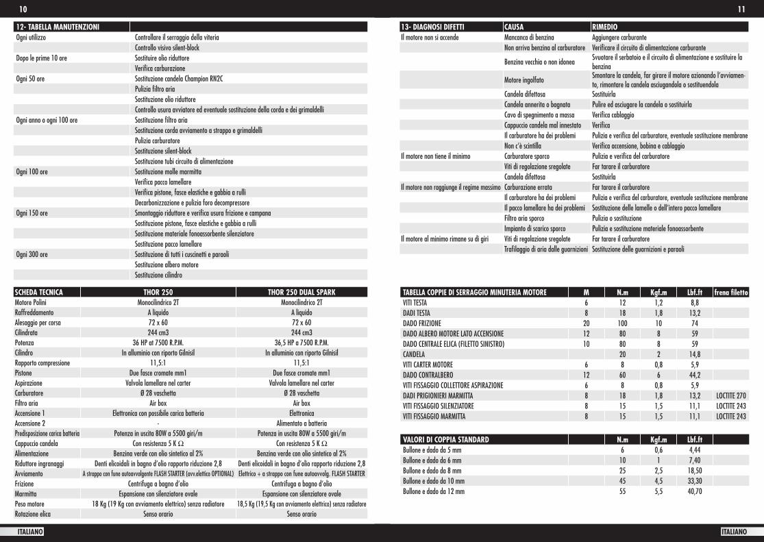
12- TABELLA MANUTENZIONIOgni utilizzo Controllare il serraggio della viteria
Controllo visivo silent-blockDopo le prime 10 ore Sostituire olio riduttore
Verifica carburazioneOgni 50 ore Sostituzione candela Champion RN2C
Pulizia filtro ariaSostituzione olio riduttoreControllo usura avviatore ed eventuale sostituzione della corda e dei grimaldelli
Ogni anno o ogni 100 ore Sostituzione filtro ariaSostituzione corda avviamento a strappo e grimaldelliPulizia carburatoreSostituzione silent-blockSostituzione tubi circuito di alimentazione
Ogni 100 ore Sostituzione molle marmittaVerifica pacco lamellareVerifica pistone, fasce elastiche e gabbia a rulliDecarbonizzazione e pulizia foro decompressore
Ogni 150 ore Smontaggio riduttore e verifica usura frizione e campanaSostituzione pistone, fasce elastiche e gabbia a rulliSostituzione materiale fonoassorbente silenziatoreSostituzione pacco lamellare
Ogni 300 ore Sostituzione di tutti i cuscinetti e paraoliSostituzione albero motoreSostituzione cilindro
SCHEDA TECNICA THOR 250 THOR 250 DUAL SPARKMotore Polini Monocilindrico 2T Monocilindrico 2TRaffreddamento A liquido A liquidoAlesaggio per corsa 72 x 60 72 x 60Cilindrata 244 cm3 244 cm3Potenza 36 HP at 7500 R.P.M. 36,5 HP a 7500 R.P.M.Cilindro In alluminio con riporto Gilnisil In alluminio con riporto Gilnisil Rapporto compressione 11,5:1 11,5:1Pistone Due fasce cromate mm1 Due fasce cromate mm1Aspirazione Valvola lamellare nel carter Valvola lamellare nel carterCarburatore Ø 28 vaschetta Ø 28 vaschettaFiltro aria Air box Air boxAccensione 1 Elettronica con possibile carica batteria ElettronicaAccensione 2 - Alimentato a batteria Predisposizione carica batteria Potenza in uscita 80W a 5500 giri/m Potenza in uscita 80W a 5500 giri/mCappuccio candela Con resistenza 5 K Ω Con resistenza 5 K ΩAlimentazione Benzina verde con olio sintetico al 2% Benzina verde con olio sintetico al 2% Riduttore ingranaggi Denti elicoidali in bagno d’olio rapporto riduzione 2,8 Denti elicoidali in bagno d’olio rapporto riduzione 2,8Avviamento A strappo con fune autoavvolgente FLASH STARTER (avv.elettico OPTIONAL) Elettrico + a strappo con fune autoavvolg. FLASH STARTERFrizione Centrifuga a bagno d’olio Centrifuga a bagno d’olio Marmitta Espansione con silenziatore ovale Espansione con silenziatore ovalePeso motore 18 Kg (19 Kg con avviamento elettrico) senza radiatore 18,5 Kg (19,5 Kg con avviamento elettrico) senza radiatoreRotazione elica Senso orario Senso orario
TABELLA COPPIE DI SERRAGGIO MINUTERIA MOTORE M N.m Kgf.m Lbf.ft frena filettoVITI TESTA 6 12 1,2 8,8 DADI TESTA 8 18 1,8 13,2 DADO FRIZIONE 20 100 10 74 DADO ALBERO MOTORE LATO ACCENSIONE 12 80 8 59 DADO CENTRALE ELICA (FILETTO SINISTRO) 10 80 8 59CANDELA 20 2 14,8 VITI CARTER MOTORE 6 8 0,8 5,9 DADO CONTRALBERO 12 60 6 44,2VITI FISSAGGIO COLLETTORE ASPIRAZIONE 6 8 0,8 5,9 DADI PRIGIONIERI MARMITTA 8 18 1,8 13,2 LOCTITE 270VITI FISSAGGIO SILENZIATORE 8 15 1,5 11,1 LOCTITE 243VITI FISSAGGIO MARMITTA 8 15 1,5 11,1 LOCTITE 243
VALORI DI COPPIA STANDARD N.m Kgf.m Lbf.ftBullone e dado da 5 mm 6 0,6 4,44Bullone e dado da 6 mm 10 1 7,40Bullone e dado da 8 mm 25 2,5 18,50Bullone e dado da 10 mm 45 4,5 33,30Bullone e dado da 12 mm 55 5,5 40,70
13- DIAGNOSI DIFETTI CAUSA RIMEDIOIl motore non si accende Mancanca di benzina Aggiungere carburante
Non arriva benzina al carburatore Verificare il circuito di alimentazione carburante
Benzina vecchia o non idoneaSvuotare il serbatoio e il circuito di alimentazione e sostituire la benzina
Motore ingolfatoSmontare la candela, far girare il motore azionando l’avviamen-to, rimontare la candela asciugandola o sostituendola
Candela difettosa SostituirlaCandela annerita o bagnata Pulire ed asciugare la candela o sostituirlaCavo di spegnimento a massa Verifica cablaggioCappuccio candela mal innestato VerificaIl carburatore ha dei problemi Pulizia e verifica del carburatore, eventuale sostituzione membraneNon c’è scintilla Verifica accensione, bobina e cablaggio
Il motore non tiene il minimo Carburatore sporco Pulizia e verifica del carburatoreViti di regolazione sregolate Far tarare il carburatoreCandela difettosa Sostituirla
Il motore non raggiunge il regime massimo Carburazione errata Far tarare il carburatoreIl carburatore ha dei problemi Pulizia e verifica del carburatore, eventuale sostituzione membraneIl pacco lamellare ha dei problemi Sostituzione delle lamelle o dell’intero pacco lamellareFiltro aria sporco Pulizia o sostituzioneImpianto di scarico sporco Pulizia e sostituzione materiale fonoassorbente
Il motore al minimo rimane su di giri Viti di regolazione sregolate Far tarare il carburatoreTrafilaggio di aria dalle guarnizioni Sostituzione delle guarnizioni e paraoli
13
ENGLISH
12
ITALIANO
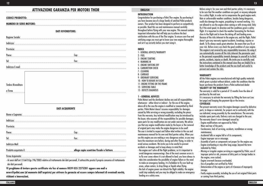
ATTIVAZIONE GARANZIA PER MOTORI THOR
CODICE PRODOTTO:
NUMERO DI SERIE MOTORE:
DATI RIVENDITORE:
Ragione Sociale:
Indirizzo:
Provincia:
Paese: Cap:
Tel: Fax:
Indirizzo E-mail:
Timbro Rivenditore
e Firma
DATI ACQUIRENTE
Nome e Cognome:
Indirizzo:
Provincia:
Paese: Cap:
Tel: Fax:
Indirizzo Mail:
Prodotto acquistato il: allego copia scontrino fiscale o fattura
Firma Acquirente: - Ai sensi dell’art.13 del D.lgs.196/2003 relativo al trattamento dei dati personali, il sottoscritto presta il proprio consenso al trattamento dei dati personali.Vi preghiamo di inviare questo certificato via fax al numero 0039 035 2275281 oppure una mail a [email protected] (al momento dell’acquisto) per attivare la garanzia ed essere sempre informati di eventuali novità, richiami o innovazioni.
ENGLISHINTRODUCTIONCongratulation for purchasing a Polini Thor engine. By purchasing it you have become one of a large family of satisfied Polini products owners. Thor product has been designed to perform as competitively as possible. Read this use and maintenance manual carefully throughout before flying with your new engine. This manual contains important information that will help you to achieve the best satisfactions with the use of the Thor engine. To ensure care-free and satisfying usage you must get to know your new engine thoroughly and set it up correctly before you start using it.
INDEX1 - GENERAL ADVICES/WARRANTY2 - FUEL3 - ENGINE STARTING4 - RUNNING IN5 - ENGINE SWITCING OFF6 - CARBURETION CHECK7 - CLEANING8 - CARRIAGE9 - ORDINARY SERVICING10 - HOW TO BEHAVE IN FLIGHT 11- ENGINE FITTING ON THE FRAME12 - SERVICING TABLE13 - DEFECTS DIAGNOSIS
1 - GENERAL ADVICESPolini Motori and the distributor decline any and all responsibilities whatsoever - either direct or indirect - for the use of the engine, above all in the case the engine is modified or manumitted by third parties. Polini Motori doesn’t assume responsibility for damages caused by little servicing or wrong assembly, excluding the pieces from the warranty. Any technical modification may be introduced by the buyer, who assumes all the responsibilities for possible damages; spare parts for any modification are not under warranty. We advice you that any engine modification made by the buyer or the removal of original parts may make the engine dangerous to be used!The user is invited to respect and follow what written in the use and maintenance manual for his own and third parties safety. When you use this engine you are making a very dangerous action, so you may have the maximum care before, during and after flying, in order to avoid serious accidents. We invite you to be careful to prevent accidents or damages and to keep always in mind that:- the engine can’t solve all the flight problems, so it is important to avoid dangerous maneuverings. One of the most common errors is to fly over zones where it is not allowed to land; you have always to take into consideration the possibility of engine failure or the need to make an emergency landing. It is forbidden to fly over built-up areas, urban centers, to drop things or liquids when flying.- the lack of engine power can disturb the flight stability: the engine could stop suddenly and you may be obliged to make an emergency landing on a safety area.
Before using it, for your own and third parties safety, it is necessary to be sure that the weather conditions are good, or anyway adequate for a safety flight, in order not to compromise the good engine work. Rain or unfavorable weather conditions, besides being dangerous, could also damage the engine, prejudicing its normal working. It is not allowed to use the engine when raining or with strong wind. Only fly if the wind speed, its direction and the conditions grant a safety flight. It is important to check the weather forecasting for the hours close to the flight and to know the taking off and landing areas. Because of the risks inherent to the engine use, and the flight, Polini doesn’t give any warranty against accidents, breakings, injuries or death. To fly always needs great attention. Be aware that you fly at your risk. Before every use check the good condition of your engine. This engine is not covered by any responsibility insurance. By using it you automatically assume all the risks inherent the paramotor sport or the personal responsibility towards damages to yourself or to third parties, accidents, injuries or death. We invite you to carefully read the instructions contained in this manual since they are helpful for a better knowledge of the products and the use itself and useful to prevent and contain the risks.
WARRANTYAll the Polini engines are manufactured with high quality materials which grant a product without defects, under the conditions that the buyer purchases the products from a Polini authorized dealerVALIDITY OF THE WARRANTYThe warranty is valid for a period of 12 months from the date of purchase by the end user.It is necessary to activate the warranty by filling the form out (see last page) and keeping the payment slip or the invoice.COVERAGEThe present warranty covers the engine damages caused by defective parts, in shape or materials, for projects not in conformity with the use indicated, wrong assembly by the manufacturer. The warranty includes spare parts only. Delivery costs are charged to the user.The warranty doesn’t cover damaged caused by:- Engine modifications not approved by Polini;- Wear and tear of the parts; - Carelessness, lack of servicing, accidents, installations or wrong maintenance;- Accidental falls or engine fall or of its components;- Engine improper use or misusage;- Assembly of parts or components not proper for the engine use;- Engine overheating or stop after long usage, beyond the term indicated by Polini;- Missing or irregular engine servicing as suggested by Polini, use of improper petrol or oils, presence of dirty parts or foreign bodies in the engine, even sucked;- Engine overwork because overloaded;- Use of propellers not certified by Polini- Deterioration of the engine or parts of it because of improperly storage; - Faulty engine assembly, including the use of not original Polini parts or coming from third parties;
14 15
ENGLISH ENGLISH
- Damages to the engine caused by foreign bodies;- Servicing operated by persons outside Polini or by not authorized people;- Use of the engine for competition purposes
- Final user obligationsClaims shall be done by delivering the engine to a Polini authorized dealer. The user shall provide the original document that proves the purchasing or the warranty ticket authenticated by Polini or by its distributor. To keep the validity of the warranty the user shall carry out recurrent servicing according to the use and maintenance manual.- Limited liabilityPursuant to this warranty, Polini’s obligations are limited to the defective parts reparation or, at its discretion, to change one or more parts, necessary to remedy every malfunctioning caused by defective materials or labor covered by the warranty. Polini or the distributor can’t be held responsible for problems or damages to persons/things/animals during the engine life. We remind you that this product is not certificated and it is only dedicated to experimental aircraft and that it can break or suddenly stop working. No warranty or compensation is foreseen for damages caused to:- persons/animals/things during the engine use- persons/animals/things caused by a collide with the propeller or with parts detached from the engine- frame, parts and/or propeller caused by the collide with parts coming out from the engine- costs for rescue, shipping, phone or rent after the collide, problems or loss of time, or other indirect damages.
Danger! This not-certified engine can suddenly stop working. The engine stop can require emergency landings causing injuries or death. The aircraft thrusts by this engine should fly in open spaces only or during the daylight. The buyer assumes all the risks for the use and he knows that by using it the engine can suddenly stop working. This product is not covered by products and public liability. Who flies with this engine or only switches it on assumes all the risks inherent to engine flying sport and all the responsibilities for damages to things or persons or death caused by the use of this product.On accounts of this, the guarantee does not cover damages caused by the installation of the engines on machines that requires certified engines, on machines that are not adequate, on machines that requires different type of engine. The vendor won’t be responsible for damages caused by the users or third parties.
2 - FUELThor is a 2-stroke engine that needs oil/petrol mixture. Only use good lead-free petrol purchased by a petrol station with 98 octanes. Add good 2% synthetic oil to the petrol. It is possible to use a 1,5% oil mixture with the following oils: MOTUL 800-VALVOLINE RACING 2T FULL SYNTHETIC SAE 50 - BARDAL KXT - ELF 976 – ELF 909Never keep the petrol into containers for a long time because its quality will be damaged. Only use certified metallic containers for petrol carriage. Mix up the petrol with the oil ONLY when you are using it.
WARNING: The nature of the carbon deposits on the cylinder head, spark plug and exhaust port give important information about the fuel mixture burning in your engine. Remember that mixes that contain too much oil do not extend the engine’s life.
ATTENTION: petrol is extremely inflammable and explosive. Carry out these operations in a well ventilate place and with the engine switched off. Refrain from smoking and avoid all naked flames or sparks where petrol is being drained or where re-fuelling is being performed.ATTENTION! For American customers only. The European range of octane is different from the American one:e.g. EU 95 OCTANE = US 91 OCTANE / EU 98 OCTANE = US 93 OCTANEFor THOR engines you have to use a high-octane gasoline (not less than US 91)
3- ENGINE STARTINGStart the engine only when all is in good conditions and perfectly working and check that there aren’t persons, things or animals around. Furthermore check that all the nuts are well tightened.
3.1- MANUAL STARTERFill in the fuel system till the petrol reaches the carburetor hole and then pump up three times (using the Polini manual bulb- Code 316.0016) to fill in the bowl. To start the engine pull upwards the black level placed in the upper side of the carburettor. Operate the starter without accelerating till the engine starts. Once it runs switch it off, disconnect the starter and start the engine again slightly accelerating. For your safety only start the engine after your harness has been COMPLETELY fixed!
3.2- ELECTRIC STARTERFill the fuel system in as shown in the previous paragraph.If your engine is equipped with a Polini throttle control press the two black buttons together and slightly accelerate till the engine runs. If necessary operate the starter to make the engine starter easier when it is cold. If the engine is not equipped with a Polini throttle control please refer to the instructions of the vehicle’s manufacturer to find out the switch on/off buttons.
ATTENTION: keep the switch in your hand during all the stages and be ready to operate it in case of any technical fault. If necessary keep it pressed till the engine has completely stopped.Once the engine starts we suggest testing the right functioning of the kill switch button. After having checked it, start the engine again without accelerating and without using the starter. Now start the engine and leave it idling until it warms up to normal operating temperature.
3.3- THOR 250 DUAL SPARK ELECTRIC STARTER AND IGNITIONS TESTSFill the fuel system as indicated in paragraph 3.1.Thor 250 DUAL SPARK engine has a control console with a cut-out switch (photo 1) that must be fixed in a comfortable position and easy
to be reached by the pilot. The engine has two separated ignitions and the console let you check the correct working of both the ignitions.When the ignition is on OFF position the engine is switched off and the electric starter does not work. By moving the switch to ON position the led will light. Use the central black key (START) to start the engine. After having started the engine keep KEY 1 pressed to disable ignition 1 and it is possible to check the correct working of ignition 2. The engine must keep on working. Now release KEY 1.Repeat the test keeping KEY 2 pressed. It disables ignition 2 and it is possible to check the correct working of ignition 1. The engine must keep on working. Now release KEY 2.Now to end the test press KEY1 and KEY2 simultaneously, so disabling both the ignitions. The engine now has to stop.Now start the engine again and it is ready to fly.NOTE 1: to switch the engine off in standard conditions use the switch moving the level in OFF position.NOTE 2: The secondary electronic ignition works using the battery. This ignition, if fed, (switch in ON position) has an electric input even with the engine switched off. This input can discharge the battery in a few days. It is important to re-position the cut-out switch in OFF position. (LED switched off)NOTE 3: If the battery should be completely discharged it is possible to use the engine by starting it manually. Keep into consideration that till the battery does not reach a minimum charge level the engine will work with one ignition only.
4- RUNNING INRun your engine in as instructed below to ensure that the engine and transmission bed in correctly and to ensure continuous reliability in future. Once the engine starts, leave it idling until it warms up to normal temperature. We suggest running the engine 15 minutes at medium-low engine power output gently accelerating and with different intensity. Now we suggest checking the correct idling calibration. During the first flights or for the first 20 litres of petrol we suggest not keeping the engine at the maximum rpm for too much time, considering that the 2-stroke engine doesn’t stand to the constant rpm even if of medium power. We suggest varying the engine rpm. Check the carburetion after the first landing. Repeat the running in every time you change one of the following parts: piston, piston rings, cylinder, crankshaft or main bearings.
5- ENGINE SWITCHING OFFSwitch the engine off by pressing the button till the complete stop.If the engine is equipped with the Polini throttle control the switch off button is of red colour and you find it in the upper side; otherwise refer to the frame/throttle’s manufacturer to find out the switch off button. For the Thor 250 Dual Spark move the lever of the control board in OFF position to disconnect simultaneously both the ignitions and switch the engine off
6- CARBURETIONThe carburetion setting must be executed by professional people only. It is possible to make a fast analysis of the carburetion by checking
the spark plug colour. To do it, switch the engine off after having run it for some second under charge. Remove the spark plug unscrewing it with the proper tool and verify the colour of the porcelain that must be of light-brown colour with tendency to dark. A light colour of the spark plug electrode means a lean carburetion; if you use the engine in this conditions may cause the engine failure. Do not use the engine in these conditions and apply to an authorized retailer to set it up.
7- CLEANINGClean the engine when it is switched off and cold to avoid burns. Clean the engine with a soft cloth soaked with neutral cleansing and non-aggressive.
WARNING: Do not use acids that may damage the engine.
8- CARRIAGEATTENTION: Carry the engine only when it is cold.
Follow the frame manufacturer’s instructions for its carriage and how to use the fuel tank during its carriage. Be careful of the petrol during the carriage: its leaking may cause a fire.
ATTENTION: During the carriage of the engine it is strictly recommended to maintain the propeller locked together with its nut in order to avoid that the flange thread that sticks out may be damaged or in case of fall it might break the crankshaft.
8.1- CARRIAGE OF THE ENGINE WITH BOWL CARBURETORThe bowl carburetor has a breather pipe studied to carry the engine when lying. To empty the carburettor unscrew half turn the breather brass nut (highlighted in photo 2 with an arrow) and wait till all the fuel enters the tank. Tighten the brass connection again. Now the carburettor is empty and you can lay the engine ready to be carried.
ATTENTION: never unscrew more than half a turn the breather nut to avoid damaging the OR seal. Never tight too hard.
9- ORDINARY SERVICINGATTENTION: THE SERVICING OPERATIONS MUST BE DONE BY
QUALIFIED PEOPLE ONLY. IF THE INSTRUCTIONS MENTIONED BELOW WILL RESULT NOT CLEAR, WE SUGGEST ASKING FOR SPECIALISTS BY POLINI MOTORI RETAILERS OR WHOLESALERS. FOLLOW CAREFULLY WHAT DESCRIBED BELOW. Maintenances and servicing necessary for the best set up of your engine should be done regularly, or on all occasions before you start your engine. All the tasks and adjustments described below can be done easily by following the instructions given in this manual. Refer to your POLINI MOTORI dealer for scheduled services and repairs, and insist that only original spare parts are used to replace worn or broken components. Refer to the servicing tables in sections 12 below for the frequency with which the various servicing operations must be performed.
9.1- REMOVE AND CLEAN THE AIR FILTERDirty air filter is one of the most common causes of poor engine performance. Clean the filter periodically or change it. Remove the filter loosening the clamps, unscrew the 4 screws using a cross screwdriver, remove the filter cover and then the filter. Wash the
16 17
ENGLISH ENGLISH
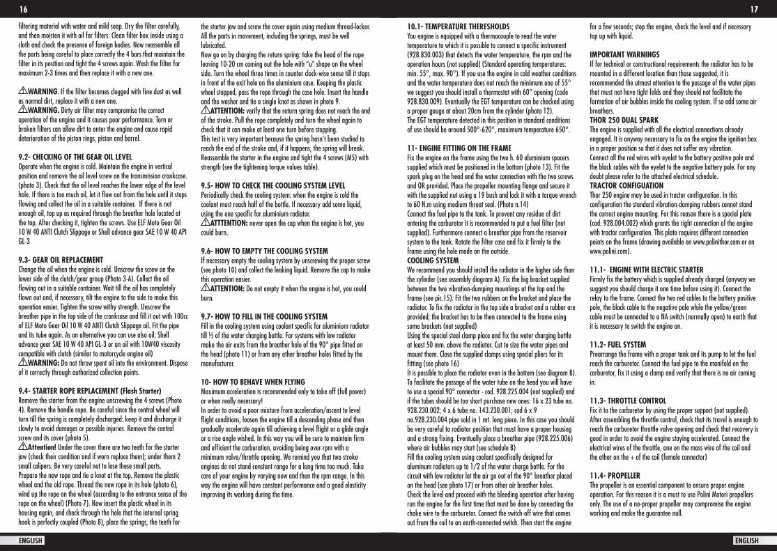
filtering material with water and mild soap. Dry the filter carefully, and then moisten it with oil for filters. Clean filter box inside using a cloth and check the presence of foreign bodies. Now reassemble all the parts being careful to place correctly the 4 bars that maintain the filter in its position and tight the 4 screws again. Wash the filter for maximum 2-3 times and then replace it with a new one.
WARNING. If the filter becomes clogged with fine dust as well as normal dirt, replace it with a new one.
WARNING. Dirty air filter may compromise the correct operation of the engine and it causes poor performance. Torn or broken filters can allow dirt to enter the engine and cause rapid deterioration of the piston rings, piston and barrel.
9.2- CHECKING OF THE GEAR OIL LEVELOperate when the engine is cold. Maintain the engine in vertical position and remove the oil level screw on the transmission crankcase. (photo 3). Check that the oil level reaches the lower edge of the level hole. If there is too much oil, let it flow out from the hole until it stops flowing and collect the oil in a suitable container. If there is not enough oil, top up as required through the breather hole located at the top. After checking it, tighten the screws. Use ELF Moto Gear Oil 10 W 40 ANTI Clutch Slippage or Shell advance gear SAE 10 W 40 API GL-3
9.3- GEAR OIL REPLACEMENTChange the oil when the engine is cold. Unscrew the screw on the lower side of the clutch/gear group (Photo 3-A). Collect the oil flowing out in a suitable container. Wait till the oil has completely flown out and, if necessary, tilt the engine to the side to make this operation easier. Tighten the screw withy strength. Unscrew the breather pipe in the top side of the crankcase and fill it out with 100cc of ELF Moto Gear Oil 10 W 40 ANTI Clutch Slippage oil. Fit the pipe and its tube again. As an alternative you can use also oil: Shell advance gear SAE 10 W 40 API GL-3 or an oil with 10W40 viscosity compatible with clutch (similar to motorcycle engine oil)
WARNING: Do not throw spent oil into the environment. Dispose of it correctly through authorized collection points.
9.4- STARTER ROPE REPLACEMENT (Flash Starter)Remove the starter from the engine unscrewing the 4 screws (Photo 4). Remove the handle rope. Be careful since the central wheel will turn till the spring is completely discharged: keep it and discharge it slowly to avoid damages or possible injuries. Remove the central screw and its cover (photo 5).
Attention! Under the cover there are two teeth for the starter jaw (check their condition and if worn replace them); under them 2 small calipers. Be very careful not to lose these small parts.Prepare the new rope and tie a knot at the top. Remove the plastic wheel and the old rope. Thread the new rope in its hole (photo 6), wind up the rope on the wheel (according to the entrance sense of the rope on the wheel) (Photo 7). Now insert the plastic wheel in its housing again, and check through the hole that the internal spring hook is perfectly coupled (Photo 8), place the springs, the teeth for
the starter jaw and screw the cover again using medium thread-locker. All the parts in movement, including the springs, must be well lubricated.Now go on by charging the return spring: take the head of the rope leaving 10-20 cm coming out the hole with “u” shape on the wheel side. Turn the wheel three times in counter clock-wise sense till it stops in front of the exit hole on the aluminium case. Keeping the plastic wheel stopped, pass the rope through the case hole. Insert the handle and the washer and tie a single knot as shown in photo 9.
ATTENTION: verify that the return spring does not reach the end of the stroke. Pull the rope completely and turn the wheel again to check that it can make at least one turn before stopping.This test is very important because the spring hasn’t been studied to reach the end of the stroke and, if it happens, the spring will break. Reassemble the starter in the engine and tight the 4 screws (M5) with strength (see the tightening torque values table).
9.5- HOW TO CHECK THE COOLING SYSTEM LEVELPeriodically check the cooling system: when the engine is cold the coolant must reach half of the bottle. If necessary add some liquid, using the one specific for aluminium radiator.
ATTTENTION: never open the cap when the engine is hot, you could burn.
9.6- HOW TO EMPTY THE COOLING SYSTEMIf necessary empty the cooling system by unscrewing the proper screw (see photo 10) and collect the leaking liquid. Remove the cap to make this operation easier.
ATTENTION: Do not empty it when the engine is hot, you could burn.
9.7- HOW TO FILL IN THE COOLING SYSTEMFill in the cooling system using coolant specific for aluminium radiator till ½ of the water charging bottle. For systems with low radiator make the air exits from the breather hole of the 90° pipe fitted on the head (photo 11) or from any other breather holes fitted by the manufacturer.
10- HOW TO BEHAVE WHEN FLYING Maximum acceleration is recommended only to take off (full power) or when really necessary!In order to avoid a poor mixture from acceleration/ascent to level flight conditions, loosen the engine till a descending phase and then gradually accelerate again till achieving a level flight or a glide angle or a rise angle wished. In this way you will be sure to maintain firm and efficient the carburation, avoiding being over rpm with a minimum valve/throttle opening. We remind you that two stroke engines do not stand constant range for a long time too much. Take care of your engine by varying now and then the rpm range. In this way the engine will have constant performance and a good elasticity improving its working during the time.
10.1- TEMPERATURE THERESHOLDSYou engine is equipped with a thermocouple to read the water temperature to which it is possible to connect a specific instrument (928.830.003) that detects the water temperature, the rpm and the operation hours (not supplied) (Standard operating temperatures: min. 55°, max. 90°). If you use the engine in cold weather conditions and the water temperature does not reach the minimum one of 55° we suggest you should install a thermostat with 60° opening (code 928.830.009). Eventually the EGT temperature can be checked using a proper gauge at about 20cm from the cylinder (photo 12).The EGT temperature detected in this position in standard conditions of use should be around 500°-620°, maximum temperature 650°.
11- ENGINE FITTING ON THE FRAMEFix the engine on the frame using the two h. 60 aluminium spacers supplied which must be positioned in the bottom (photo 13). Fit the spark plug on the head and the water connection with the two screws and OR provided. Place the propeller mounting flange and secure it with the supplied nut using a 19 bush and lock it with a torque wrench to 60 N.m using medium threat seal. (Photo n.14)Connect the fuel pipe to the tank. To prevent any residue of dirt entering the carburetor it is recommended to put a fuel filter (not supplied). Furthermore connect a breather pipe from the reservoir system to the tank. Rotate the filter case and fix it firmly to the frame using the hole made on the outside.COOLING SYSTEMWe recommend you should install the radiator in the higher side than the cylinder (see assembly diagram A). Fix the big bracket supplied between the two vibration-dumping mountings at the top and the frame (see pic.15). Fit the two rubbers on the bracket and place the radiator. To fix the radiator in the top side a bracket and a rubber are provided; the bracket has to be then connected to the frame using some brackets (not supplied) Using the special steel clamp place and fix the water charging bottle at least 50 mm. above the radiator. Cut to size the water pipes and mount them. Close the supplied clamps using special pliers for its fitting (see photo 16)It is possible to place the radiator even in the bottom (see diagram B). To facilitate the passage of the water tube on the head you will have to use a special 90° connector - cod. 928.225.004 (not supplied) and if the tubes should be too short purchase new ones: 16 x 23 tube no. 928.230.002; 4 x 6 tube no. 143.230.001; cod 6 x 9 no.928.230.004 pipe sold in 1 mt. long piece. In this case you should be very careful to radiator position that must have a proper housing and a strong fixing. Eventually place a breather pipe (928.225.006) where air bubbles may start (see schedule B)Fill the cooling system using coolant specifically designed for aluminum radiators up to 1/2 of the water charge bottle. For the circuit with low radiator let the air go out of the 90° breather placed on the head (see photo 17) or from other air breather holes.Check the level and proceed with the bleeding operation after having run the engine for the first time that must be done by connecting the choke wire to the carburetor. Connect the switch-off wire that comes out from the coil to an earth-connected switch. Then start the engine
for a few seconds; stop the engine, check the level and if necessary top up with liquid.
IMPORTANT WARNINGSIf for technical or constructional requirements the radiator has to be mounted in a different location than those suggested, it is recommended the utmost attention to the passage of the water pipes that must not have tight folds and they should not facilitate the formation of air bubbles inside the cooling system. If so add some air breathers. THOR 250 DUAL SPARKThe engine is supplied with all the electrical connections already engaged. It is anyway necessary to fix on the engine the ignition box in a proper position so that it does not suffer any vibration.Connect all the red wires with eyelet to the battery positive pole and the black cables with the eyelet to the negative battery pole. For any doubt please refer to the attached electrical schedule.TRACTOR CONFIGUATION Thor 250 engine may be used in tractor configuration. In this configuration the standard vibration-damping rubbers cannot stand the correct engine mounting. For this reason there is a special plate (cod. 928.004.002) which grants the right connection of the engine with tractor configuration. This plate requires different connection points on the frame (drawing available on www.polinithor.com or on www.polini.com).
11.1- ENGINE WITH ELECTRIC STARTERFirmly fix the battery which is supplied already charged (anyway we suggest you should charge it one time before using it). Connect the relay to the frame. Connect the two red cables to the battery positive pole, the black cable to the negative pole while the yellow/green cable must be connected to a NA switch (normally open) to earth that it is necessary to switch the engine on.
11.2- FUEL SYSTEMPrearrange the frame with a proper tank and its pump to let the fuel reach the carburetor. Connect the fuel pipe to the manifold on the carburetor, fix it using a clamp and verify that there is no air coming in.
11.3- THROTTLE CONTROLFix it to the carburetor by using the proper support (not supplied). After assembling the throttle control, check that its travel is enough to reach the carburetor throttle valve opening and check that recovery is good in order to avoid the engine staying accelerated. Connect the electrical wires of the throttle, one on the mass wire of the coil and the other on the + of the coil (female connector)
11.4- PROPELLERThe propeller is an essential component to ensure proper engine operation. For this reason it is a must to use Polini Motori propellers only. The use of a no-proper propeller may compromise the engine working and make the guarantee null.
18 19
ENGLISH ENGLISH
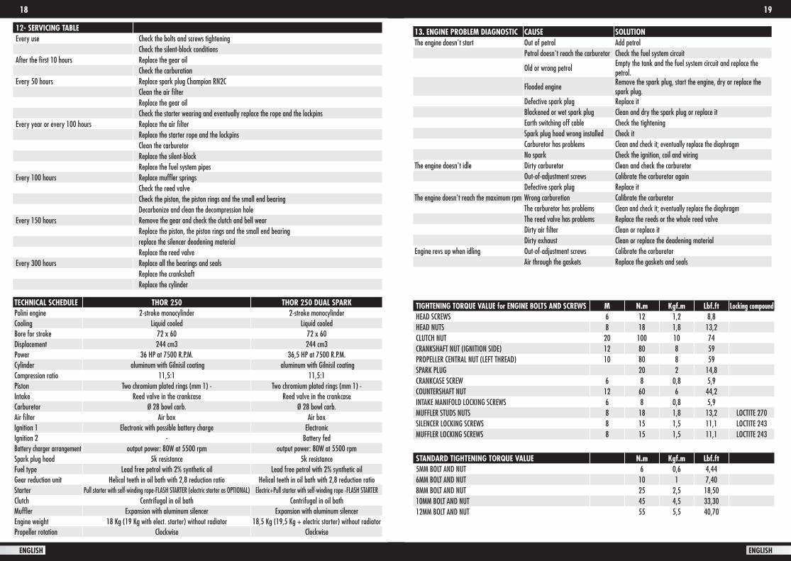
12- SERVICING TABLEEvery use Check the bolts and screws tightening
Check the silent-block conditionsAfter the first 10 hours Replace the gear oil
Check the carburationEvery 50 hours Replace spark plug Champion RN2C
Clean the air filterReplace the gear oilCheck the starter wearing and eventually replace the rope and the lockpins
Every year or every 100 hours Replace the air filterReplace the starter rope and the lockpinsClean the carburetorReplace the silent-blockReplace the fuel system pipes
Every 100 hours Replace muffler springsCheck the reed valveCheck the piston, the piston rings and the small end bearingDecarbonize and clean the decompression hole
Every 150 hours Remove the gear and check the clutch and bell wearReplace the piston, the piston rings and the small end bearingreplace the silencer deadening material Replace the reed valve
Every 300 hours Replace all the bearings and sealsReplace the crankshaftReplace the cylinder
TECHNICAL SCHEDULE THOR 250 THOR 250 DUAL SPARKPolini engine 2-stroke monocylinder 2-stroke monocylinder Cooling Liquid cooled Liquid cooledBore for stroke 72 x 60 72 x 60Displacement 244 cm3 244 cm3Power 36 HP at 7500 R.P.M. 36,5 HP at 7500 R.P.M.Cylinder aluminum with Gilnisil coating aluminum with Gilnisil coatingCompression ratio 11,5:1 11,5:1Piston Two chromium plated rings (mm 1) - Two chromium plated rings (mm 1) - Intake Reed valve in the crankcase Reed valve in the crankcase Carburetor Ø 28 bowl carb. Ø 28 bowl carb.Air filter Air box Air boxIgnition 1 Electronic with possible battery charge ElectronicIgnition 2 - Battery fedBattery charger arrangement output power: 80W at 5500 rpm output power: 80W at 5500 rpmSpark plug hood 5k resistance 5k resistanceFuel type Lead free petrol with 2% synthetic oil Lead free petrol with 2% synthetic oil Gear reduction unit Helical teeth in oil bath with 2,8 reduction ratio Helical teeth in oil bath with 2,8 reduction ratioStarter Pull starter with self-winding rope-FLASH STARTER (electric starter as OPTIONAL) Electric+Pull starter with self-winding rope -FLASH STARTER Clutch Centrifugal in oil bath Centrifugal in oil bathMuffler Expansion with aluminum silencer Expansion with aluminum silencerEngine weight 18 Kg (19 Kg with elect. starter) without radiator 18,5 Kg (19,5 Kg + electric starter) without radiatorPropeller rotation Clockwise Clockwise
TIGHTENING TORQUE VALUE for ENGINE BOLTS AND SCREWS M N.m Kgf.m Lbf.ft Locking compoundHEAD SCREWS 6 12 1,2 8,8 HEAD NUTS 8 18 1,8 13,2 CLUTCH NUT 20 100 10 74 CRANKSHAFT NUT (IGNITION SIDE) 12 80 8 59 PROPELLER CENTRAL NUT (LEFT THREAD) 10 80 8 59SPARK PLUG 20 2 14,8 CRANKCASE SCREW 6 8 0,8 5,9 COUNTERSHAFT NUT 12 60 6 44,2INTAKE MANIFOLD LOCKING SCREWS 6 8 0,8 5,9 MUFFLER STUDS NUTS 8 18 1,8 13,2 LOCTITE 270SILENCER LOCKING SCREWS 8 15 1,5 11,1 LOCTITE 243MUFFLER LOCKING SCREWS 8 15 1,5 11,1 LOCTITE 243
STANDARD TIGHTENING TORQUE VALUE N.m Kgf.m Lbf.ft5MM BOLT AND NUT 6 0,6 4,446MM BOLT AND NUT 10 1 7,408MM BOLT AND NUT 25 2,5 18,5010MM BOLT AND NUT 45 4,5 33,3012MM BOLT AND NUT 55 5,5 40,70
13. ENGINE PROBLEM DIAGNOSTIC CAUSE SOLUTIONThe engine doesn't start Out of petrol Add petrol
Petrol doesn't reach the carburetor Check the fuel system circuit
Old or wrong petrol Empty the tank and the fuel system circuit and replace the petrol.
Flooded engine Remove the spark plug, start the engine, dry or replace the spark plug.
Defective spark plug Replace itBlackened or wet spark plug Clean and dry the spark plug or replace itEarth switching off cable Check the tightening Spark plug hood wrong installed Check itCarburetor has problems Clean and check it; eventually replace the diaphragmNo spark Check the ignition, coil and wiring
The engine doesn't idle Dirty carburetor Clean and check the carburetorOut-of-adjustment screws Calibrate the carburetor againDefective spark plug Replace it
The engine doesn't reach the maximum rpm Wrong carburetion Calibrate the carburetorThe carburetor has problems Clean and check it; eventually replace the diaphragmThe reed valve has problems Replace the reeds or the whole reed valveDirty air filter Clean or replace itDirty exhaust Clean or replace the deadening material
Engine revs up when idling Out-of-adjustment screws Calibrate the carburetorAir through the gaskets Replace the gaskets and seals
2120
ENGLISH
THOR ENGINES’ WARRANTY ACTIVATION
PART NUMBER:
ENGINE SERIES NUMBER:
DEALER’S DATA:
Company name:
Address:
City:
Country: ZIP Code:
Phone number: Fax number:
E-Mail Address:
Dealer’s stamp
and Signature
PURCHASER’S DATA
Name and Surname:
Address:
City:
Country: ZIP Code:
Phone number : Fax number :
E-Mail Address:
Product purchased on: I enclose a copy of receipt/invoice
Purchaser’s signature: - Pursuant to Art. 13 of Legislative Decree No. 196/2003 concerning the treatment of the personal data, the undersigned authorize the treatment of the transmitted personal data.Kindly send this certificate by fax to the following number 0039 035 2275281 or by mail to [email protected] (at the moment of your purchase) in order to activate the warranty and be always informed about news, recalls or innovations.

Polini Motori S.p.A. Viale Piave, 30 - 24022 Alzano Lombardo (BG) - Italy Tel. +39 035 2275111 - Fax +39 035 2275281 www.polini.com
PI 48206A15