
SP 2300 - ibki.nl · ne della produzione standard possono differire ... -on dimenticare mai sulla...
104
Italiano Manuale d’uso + pezzi di ricambio 3 English Operator’s manual + spare parts 21 Français Manuel d’utilisation + rechange 39 Deutsch Betriebsanleitung + Ersatzteillisten 57 Español Manual de uso + repuestos 75 SP 2300 Cod. 4-113212A - 06/2012 STD WDK
Transcript of SP 2300 - ibki.nl · ne della produzione standard possono differire ... -on dimenticare mai sulla...
Italiano Manuale d’uso + pezzi di ricambio 3
English Operator’s manual + spare parts 21
Français Manuel d’utilisation + rechange 39
Deutsch Betriebsanleitung + Ersatzteillisten 57
Español Manual de uso + repuestos 75
SP 2300Cod. 4-113212A - 06/2012
STD
WDK

2 SP 2300 - Manuale d’uso + pezzi di ricambio
Elaborazione grafica e impaginazione
Ufficio Pubblicazioni Tecniche
Idiritti di traduzione, di memorizzazione elettronica, di riproduzione e di adattamento totale o parziale con qualsiasi
mezzo (compresi microfilm e copie fotostatiche) sono riservati.Le informazioni contenute in questo manuale sono soggette a variazioni senza preavviso.
L es droits de traduction, de mémorisation électronique, de reproduction et d’adaptation complète ou partielle par tout
type de moyen (y compris microfilms et copies photostatiques) sont réservés.Les informations fournies dans ce manuel peuvent être modi-fiées à tout moment et sans préavis.
Alle Rechte der Übersetzung, der Speicherung, Reproduk tion sowie der gesamten oder teilweisen Anpassung durch
ein beliebiges Mittel (einschließlich Mikrofilm und Fotokopien) sind vorbehalten.Die in diesem Handbuch enthaltenen Informationen können ohne Vorbescheid geändert werden.
Quedan reservados los derechos de traducción, de me-morización electrónica, de reproducción y de adaptación
total o parcial con cualquier medio (incluidos microfilmes y fotocopias).Las informaciones contenidas en el presente manual pueden sufrir variaciones sin aviso previo.
English
Italiano
Español
Deutsch
Français
All rights reserved. No part of this publication may be translated, stored in an electronic retrieval system, repro-
duced, or partially or totally adapted by any means (including microfilm and photostats) without prior permission.The information contained herein may be subject to modifica-tions without prior notice.
SP 2300 - Manuale d’uso + pezzi di ricambio 3
I
SOMMARIOINTRODUZIONE ............................................................................................. 4DESCRIZIONE GRUPPI DISPONIBILI ........................................................... 5DESCRIZIONE COMBINAZIONI .................................................................... 5TRASPORTO, STOCCAGGIO E MOVIMENTAZIONE .................................. 7
Condizioni trasporto macchina e dati tecnici ....................................... 7Condizioni dell’ambiente di trasporto e stoccaggio macchina .......... 7
NORME DI SICUREZZA ................................................................................. 7INSTALLAZIONE SULLO SMONTAGOMME ............................................... 8PARTI FUNZIONALI ...................................................................................... 12
CONTROLLO CORRETTO FUNZIONAMENTO .................................... 12USO ................................................................................................................ 13
Smontaggio/Montaggio pneumatico .................................................... 13Procedura omologata di smontaggio e montaggio pneumatici UHP e Run Flat........................................................................................ 16
MANUTENZIONE ......................................................................................... 16INFORMAZIONI SULLA DEMOLIZIONE .................................................... 17MEZZI ANTINCENDIO DA UTILIZZARE..................................................... 17SCHEMA PNEUMATICO .............................................................................. 18
4 SP 2300 - Manuale d’uso + pezzi di ricambio
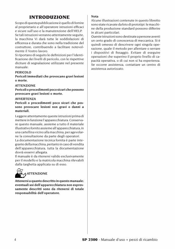
INTRODUZIONEScopo di questa pubblicazione è quello di fornire al proprietario e all’operatore istruzioni efficaci e sicure sull’uso e la manutenzione dell’HELP.Se tali istruzioni verranno attentamente seguite, la macchina Vi darà tutte le soddisfazioni di efficenza e durata che sono nella tradizione del costruttore, contribuendo a facilitare notevol-mente il Vostro lavoro.Si riportano di seguito le definizioni per l’identi-ficazione dei livelli di pericolo, con le rispettive diciture di segnalazione utilizzate nel presente manuale:
PERICOLOPericoli immediati che provocano gravi lesioni o morte.
ATTENZIONEPericoli o procedimenti poco sicuri che possono provocare gravi lesioni o morte.
AVVERTENZAPericoli o procedimenti poco sicuri che pos-sono provocare lesioni non gravi o danni a materiali.
Leggere attentamente queste istruzioni prima di mettere in funzione l’apparecchiatura. Conserva-re questo manuale, assieme a tutto il materiale illustrativo fornito assieme all’apparecchiatura, in una cartellina vicino alla macchina, per agevolar-ne la consultazione da parte degli operatori.La documentazione tecnica fornita è parte inte-grante della macchina, pertanto in caso di vendita dell’apparecchiatura, tutta la documentazione dovrà esservi allegata.Il manuale è da ritenersi valido esclusivamente per il modello e la matricola macchina rilevabili dalla targhetta applicata su di esso.
ATTENZIONE
Attenersi a quanto descritto in questo manuale: eventuali usi dell’apparecchiatura non espres-samente descritti sono da ritenersi di totale responsabilità dell’operatore.
NotaAlcune illustrazioni contenute in questo libretto sono state ricavate da foto di prototipi: le macchi-ne della produzione standard possono differire in alcuni particolari.Queste istruzioni sono destinate a persone aventi un certo grado di conoscenza di meccanica. Si è quindi omesso di descrivere ogni singola ope-razione, quale il metodo per allentare o serrare i dispositivi di fissaggio. Evitare di eseguire operazioni che superino il proprio livello di ca-pacità operativa, o di cui non si ha esperienza. Se occorre assistenza, contattare un centro di assistenza autorizzato.
SP 2300 - Manuale d’uso + pezzi di ricambio 5
I
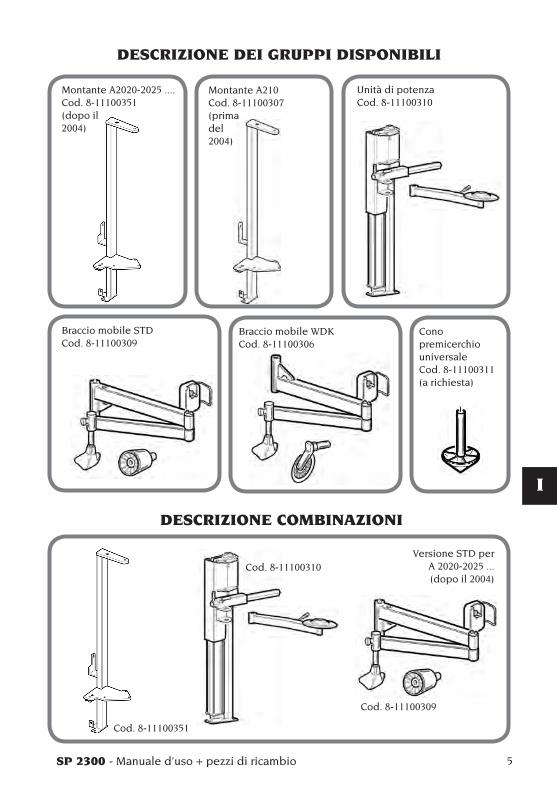
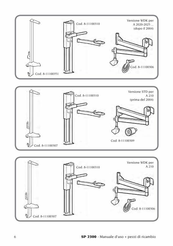
DESCRIZIONE DEI GRUPPI DISPONIBILI
Montante A2020-2025 ....Cod. 8-11100351(dopo il2004)
Montante A210Cod. 8-11100307(prima del2004)
Unità di potenzaCod. 8-11100310
Braccio mobile STDCod. 8-11100309
Braccio mobile WDKCod. 8-11100306
Conopremicerchio universaleCod. 8-11100311(a richiesta)
DESCRIZIONE COMBINAZIONI
Versione STD per A 2020-2025 ...(dopo il 2004)
Cod. 8-11100351
Cod. 8-11100310
Cod. 8-11100309
6 SP 2300 - Manuale d’uso + pezzi di ricambio
Versione WDK per A 2020-2025 ...(dopo il 2004)
Versione STD per A 210
(prima del 2004)
Versione WDK per A 210
Cod. 8-11100351
Cod. 8-11100310
Cod. 8-11100306
Cod. 8-11100307
Cod. 8-11100310
Cod. 8-11100309
Cod. 8-11100307
Cod. 8-11100310
Cod. 8-11100306
SP 2300 - Manuale d’uso + pezzi di ricambio 7
I
NORME DI SICUREZZAL’apparecchiatura é destinata ad un uso esclusi-vamente professionale.
ATTENZIONE
Sull’attrezzatura può operare un solo operatore alla volta.
ATTENZIONE
L’inosservanza delle istruzioni e delle avvertenze di pericolo, può provocare gravi lesioni agli operatori e ai presenti. Non mettere in funzione la macchina prima di aver letto e compreso tutte le segnalazioni di pericolo, attenzione e avvertenza di questo manuale.
Per operare correttamente con questa macchina occorre essere un operatore qualificato e auto-rizzato in grado di capire le istruzioni scritte date dal produttore, essere addestrato e conoscere le regole di sicurezza. Un operatore non può ingerire droghe o alcool che potrebbero alterare le sue capacità. È comunque indispensabile:- Sapere leggere e capire quanto descritto.- Conoscere le capacità e le caratteristiche di
questa macchina.- Mantenere le persone non autorizzate lontano
dalla zona di lavoro.- Accertare che l’installazione della macchina sia
stata eseguita in conformità a tutte le normative e regolamentazioni vigenti in materia.
- Accertare che tutti gli operatori siano adegua-tamente addestrati, che sappiano utilizzare l’apparecchiatura in modo corretto e sicuro e che vi sia una supervisione adeguata.
- Non dimenticare mai sulla macchina dadi, bulloni, utensili od altro che durante il lavoro potrebbero inserirsi tra parti in movimento della macchina stessa.
- Non toccare linee o l’interno di motori e appa-recchiature elettriche senza prima assicurarsi che sia stata tolta la corrente.
- Leggere con attenzione questo libretto e im-parare ad usare la macchina correttamente e in sicurezza.
- Tenere sempre disponibile in luogo facilmente accessibile questo manuale d’uso e manuten-zione e non trascurare di consultarlo.
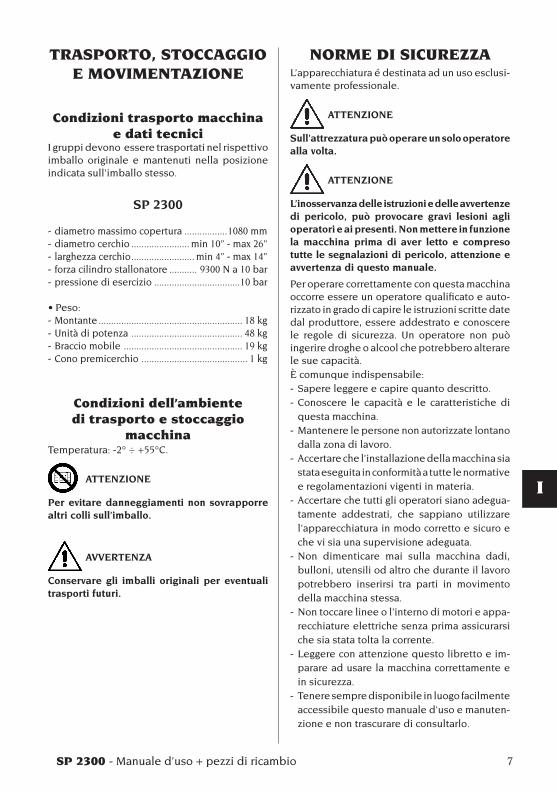
TRASPORTO, STOCCAGGIO E MOVIMENTAZIONE
Condizioni trasporto macchina e dati tecnici
I gruppi devono essere trasportati nel rispettivo imballo originale e mantenuti nella posizione indicata sull’imballo stesso.
SP 2300
- diametro massimo copertura .................1080 mm- diametro cerchio ....................... min 10” - max 26”- larghezza cerchio ......................... min 4” - max 14” - forza cilindro stallonatore ........... 9300 N a 10 bar- pressione di esercizio ..................................10 bar
•Peso:- Montante ......................................................... 18 kg - Unità di potenza ............................................ 48 kg- Braccio mobile ............................................... 19 kg- Cono premicerchio .......................................... 1 kg
Condizioni dell’ambiente di trasporto e stoccaggio
macchinaTemperatura: -2° ÷ +55°C.
ATTENZIONE
Per evitare danneggiamenti non sovrapporre altri colli sull’imballo.
AVVERTENZA
Conservare gli imballi originali per eventuali trasporti futuri.
8 SP 2300 - Manuale d’uso + pezzi di ricambio
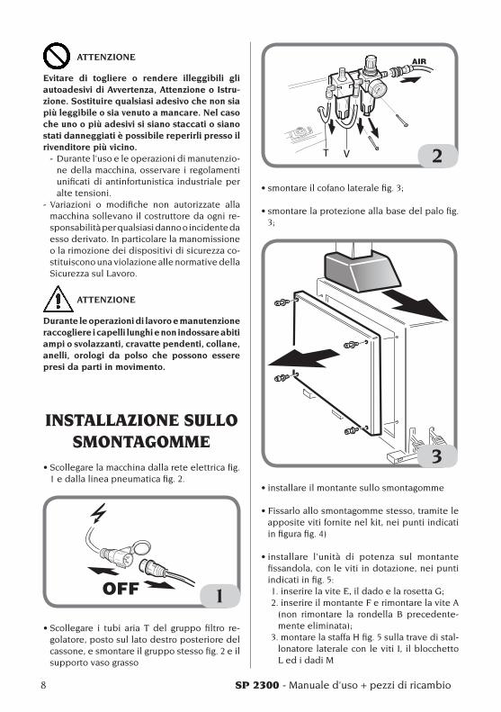
ATTENZIONE
Evitare di togliere o rendere illeggibili gli autoadesivi di Avvertenza, Attenzione o Istru-zione. Sostituire qualsiasi adesivo che non sia più leggibile o sia venuto a mancare. Nel caso che uno o più adesivi si siano staccati o siano stati danneggiati è possibile reperirli presso il rivenditore più vicino.
- Durante l’uso e le operazioni di manutenzio-ne della macchina, osservare i regolamenti unificati di antinfortunistica industriale per alte tensioni.
- Variazioni o modifiche non autorizzate alla macchina sollevano il costruttore da ogni re-sponsabilità per qualsiasi danno o incidente da esso derivato. In particolare la manomissione o la rimozione dei dispositivi di sicurezza co-stituiscono una violazione alle normative della Sicurezza sul Lavoro.
ATTENZIONE
Durante le operazioni di lavoro e manutenzione raccogliere i capelli lunghi e non indossare abiti ampi o svolazzanti, cravatte pendenti, collane, anelli, orologi da polso che possono essere presi da parti in movimento.
INSTALLAZIONE SULLO SMONTAGOMME
•Scollegarelamacchinadallareteelettricafig.1 e dalla linea pneumatica fig. 2.
1
•Scollegare i tubi aria T del gruppo filtro re-golatore, posto sul lato destro posteriore del cassone, e smontare il gruppo stesso fig. 2 e il supporto vaso grasso
T V 2
•smontareilcofanolateralefig.3;
•smontarelaprotezioneallabasedelpalofig.3;
3•installareilmontantesullosmontagomme
•Fissarloallosmontagommestesso,tramiteleapposite viti fornite nel kit, nei punti indicati in figura fig. 4)
•installare l’unità di potenza sul montantefissandola, con le viti in dotazione, nei punti indicati in fig. 5:1.inserirelaviteE,ildadoelarosettaG;2. inserire il montante F e rimontare la vite A
(non rimontare la rondella B precedente-menteeliminata);
3. montare la staffa H fig. 5 sulla trave di stal-lonatore laterale con le viti I, il blocchetto L ed i dadi M

SP 2300 - Manuale d’uso + pezzi di ricambio 9
I
4
A
B
E
F
G
HI
L
M
5
10 SP 2300 - Manuale d’uso + pezzi di ricambio
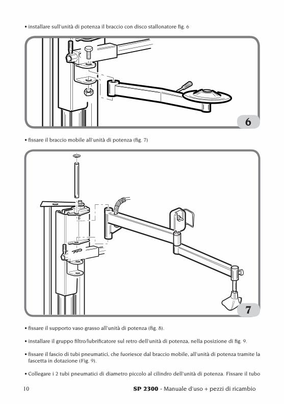
•installaresull’unitàdipotenzailbracciocondiscostallonatorefig.6
6
•fissareilbracciomobileall’unitàdipotenza(fig.7)
7
•fissareilsupportovasograssoall’unitàdipotenza(fig.8).
•installareilgruppofiltro/lubrificatoresulretrodell’unitàdipotenza,nellaposizionedifig.9.
•fissareilfascioditubipneumatici,chefuoriescedalbracciomobile,all’unitàdipotenzatramitelafascetta in dotazione (Fig. 9).
•Collegarei2tubipneumaticididiametropiccoloalcilindrodell’unitàdipotenza.Fissareiltubo

SP 2300 - Manuale d’uso + pezzi di ricambio 11
I
che va alla parte inferiore con le apposite fascette (fig. 9)
•Utilizzandoitubieiraccordiindotazioneeffet-tuare i collegamenti al gruppo filtro/regolatore come da fig. 9.
•rimontareilcofanolateraleelaprotezionepalo.
•Ricollegare lo smontagomme all’alimentazioneelettrica e pneumatica
9
8
12 SP 2300 - Manuale d’uso + pezzi di ricambio
PARTI FUNZIONALI
10
1
2
4
3
5
6
7
10
98
11
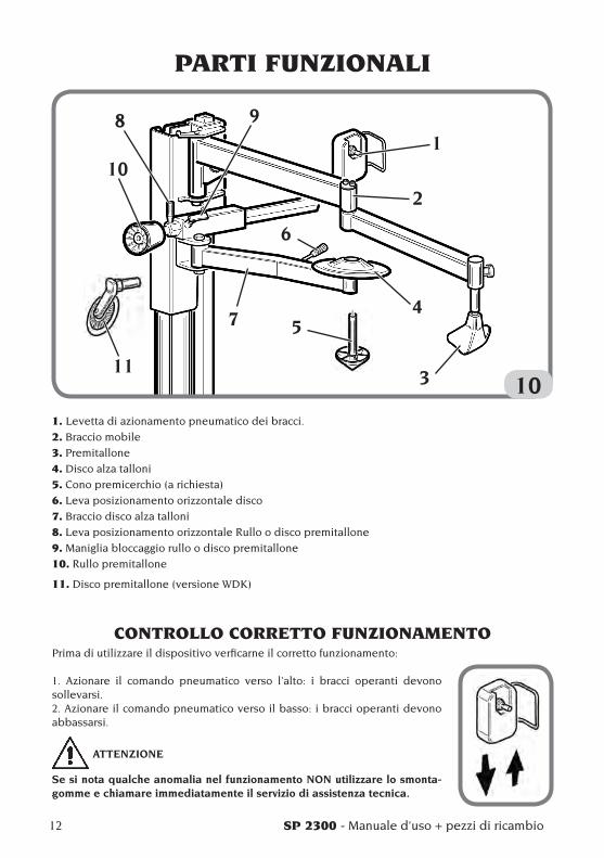
1. Levetta di azionamento pneumatico dei bracci.
2. Braccio mobile
3. Premitallone
4. Disco alza talloni
5. Cono premicerchio (a richiesta)
6. Leva posizionamento orizzontale disco
7. Braccio disco alza talloni
8. Leva posizionamento orizzontale Rullo o disco premitallone
9. Maniglia bloccaggio rullo o disco premitallone
10. Rullo premitallone
11. Disco premitallone (versione WDK)
CONTROLLO CORRETTO FUNZIONAMENTOPrima di utilizzare il dispositivo verficarne il corretto funzionamento:
1. Azionare il comando pneumatico verso l’alto: i bracci operanti devono sollevarsi.2. Azionare il comando pneumatico verso il basso: i bracci operanti devono abbassarsi.
ATTENZIONE
Se si nota qualche anomalia nel funzionamento NON utilizzare lo smonta-gomme e chiamare immediatamente il servizio di assistenza tecnica.
SP 2300 - Manuale d’uso + pezzi di ricambio 13
I
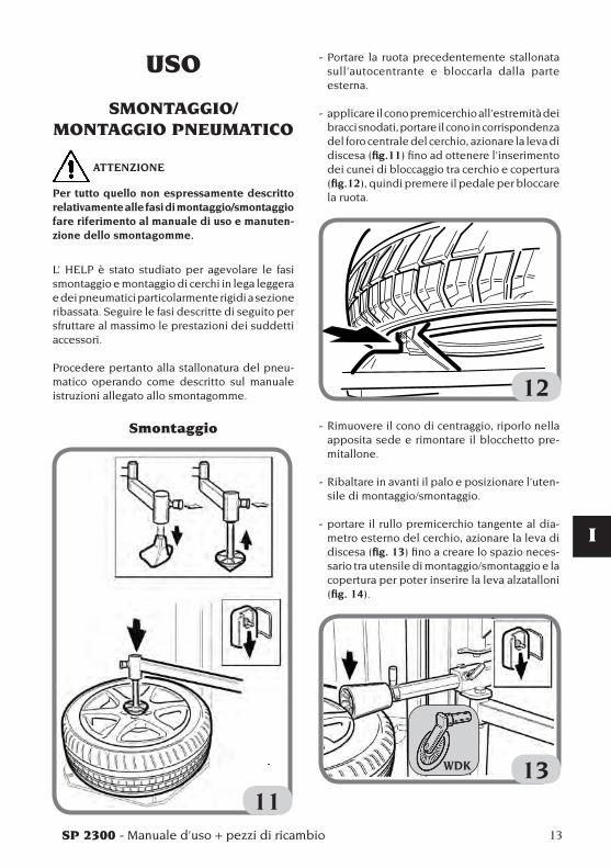
- Portare la ruota precedentemente stallonata sull’autocentrante e bloccarla dalla parte esterna.
- applicare il cono premicerchio all’estremità dei bracci snodati, portare il cono in corrispondenza del foro centrale del cerchio, azionare la leva di discesa (fig.11) fino ad ottenere l’inserimento dei cunei di bloccaggio tra cerchio e copertura (fig.12), quindi premere il pedale per bloccare la ruota.
12- Rimuovere il cono di centraggio, riporlo nella
apposita sede e rimontare il blocchetto pre-mitallone.
- Ribaltare in avanti il palo e posizionare l’uten-sile di montaggio/smontaggio.
- portare il rullo premicerchio tangente al dia-metro esterno del cerchio, azionare la leva di discesa (fig. 13) fino a creare lo spazio neces-sario tra utensile di montaggio/smontaggio e la copertura per poter inserire la leva alzatalloni (fig. 14).
13
USO
SMONTAGGIO/ MONTAGGIO PNEUMATICO
ATTENZIONE
Per tutto quello non espressamente descritto relativamente alle fasi di montaggio/smontaggio fare riferimento al manuale di uso e manuten-zione dello smontagomme.
L’ HELP è stato studiato per agevolare le fasi smontaggio e montaggio di cerchi in lega leggera e dei pneumatici particolarmente rigidi a sezione ribassata. Seguire le fasi descritte di seguito per sfruttare al massimo le prestazioni dei suddetti accessori.
Procedere pertanto alla stallonatura del pneu-matico operando come descritto sul manuale istruzioni allegato allo smontagomme.
Smontaggio
11
WDK
14 SP 2300 - Manuale d’uso + pezzi di ricambio
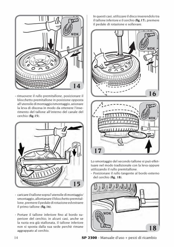
14- rimuovere il rullo premitallone, posizionare il
blocchetto premitallone in posizione opposta all’utensile di montaggio/smontaggio, azionare la leva di discesa in modo da ottenere l’inse-rimento del tallone all’interno del canale del cerchio (fig.15).
15- caricare il tallone sopra l’utensile di montaggio/
smontaggio, allontanare il blocchetto premital-lone, premere il pedale di rotazione ed estrarre il primo tallone (fig.16).
- Portare il tallone inferiore fino al bordo su-periore del cerchio; in alcuni casi, anche sela ruota era già stallonata, il tallone inferiore non si sposta dalla sua sede perchè rimane aggrappato al cerchio.
In questi casi, utilizzare il disco inserendolo tra il tallone inferiore e il cerchio (fig.17), premere il pedale di rotazione e sollevare.
16
17Lo smontaggio del secondo tallone si può effet-tuare nel modo tradizionale con la leva oppure utilizzando il rullo premitallone.- Posizionare il rullo tangente al bordo esterno
del cerchio (fig. 18).
18
WDK
WDK
WDK
WDK

SP 2300 - Manuale d’uso + pezzi di ricambio 15
I
- Sollevare il rullo fino a farlo sporgere dal bordo superiore.
- Azionare la rotazione ed estrarre la copertura. (fig. 19)
19
Montaggio pneumatici
- Appoggiare la copertura sul cerchio e richiamare in avanti il palo, montare il primo tallone (fig. 20).
20
- Posizionare il tallone superiore sotto l’uten-sile di montaggio/smontaggio, posizionare
contemporaneamente il rullo premitallone e il blocchetto premitallone vicino all’utensile di montaggio/smontaggio, azionare la leva di discesa fino ad ottenere l’abbassamento del rullo premicerchio sotto il bordo superiore del cerchio (fig. 21).
21- Premere il pedale di rotazione e montare la
copertura (fig.22).
22 In questa fase si vedrà il rullo premicerchio che
mantiene il tallone sotto la testina dell’uten-sile di montaggio/smontaggio e il blocchetto
WDKWDK
WDK
16 SP 2300 - Manuale d’uso + pezzi di ricambio
premitallone seguirà la ruota nella rotazione mantenendo il tallone all’interno del canale, garantendo così il corretto montaggio senza l’ausilio delle mani da parte dell’operatore.
NOTA: interrompere la rotazione quando il premitallone è in prossimità dell’utensile di montaggio/smontaggio.
- Azionare la leva di salita, liberare la ruota dal rullo e dal premitallone.
PROCEDURA OMOLOGATA DI SMONTAGGIO E
MONTAGGIO PNEUMATICI UHP E RUN FLAT
Per la procedura dettagliata di smontaggio/montaggio di pneumatici UHP e RUN FLAT fare riferimento alle istruzioni del manuale redatto dalla WDK (Associazione Tedesca dell’Industria del Pneumatico).
MANUTENZIONE
ATTENZIONE
Il costruttore declina ogni responsabilità in caso di reclami derivati dall’uso di ricambi o accessori non originali.
ATTENZIONE
Prima di procedere a qualsiasi regolazione o manutenzione, scollegare l’alimentazione elet-trica e pneumatica della macchina, e accertarsi che tutte le parti mobili siano bloccate.
ATTENZIONE
Non togliere o modificare alcuna parte di questa macchina (eccetto per assistenza).
PERICOLO
Prima di procedere a qualsiasi operazione di manutenzione o rabbocco lubrificante, scolle-gare la macchina dalla linea di alimentazione pneumatica.
AVVERTENZA
Tenere pulita la zona di lavoro.Non usare mai aria compressa, getti d’acqua o diluente per rimuovere sporcizia o residui dalla macchina.Nei lavori di pulizia, operare in modo da im-pedire, quando ciò sia possibile, il formarsi o il sollevarsi della polvere.

SP 2300 - Manuale d’uso + pezzi di ricambio 17
I
INFORMAZIONI SULLA
DEMOLIZIONEIn caso di demolizione della macchina, separare preventivamente i particolari elettrici, elettronici, plastici e ferrosi.Procedere quindi alla rottamazione diversificata come previsto dalle norme vigenti.
INFORMAZIONI AMBIENTALI
La seguente procedura di smaltimento deve essere applicata esclusivamente alle macchine in cui la targhetta dati macchina riporta il simbolo
del bidone barrato .
Questo prodotto può contenere sostanze che possono essere dannose per l’ambiente e per la salute umana se non viene smaltito in modo opportuno.Vi forniamo pertanto le seguenti informazioni per evitare il rilascio di queste sostanze e per migliorare l’uso delle risorse naturali.
Le apparecchiature elettriche ed elettroniche non devono essere smaltite tra i normali rifiuti urbani ma devono essere inviate alla raccolta differenziata per il loro corretto trattamento.Il simbolo del bidone barrato, apposto sul pro-dotto ed in questa pagina, ricorda la necessità di smaltire adeguatamente il prodotto al termine della sua vita.In tal modo è possibile evitare che un tratta-mento non specifico delle sostanze contenute in questi prodotti, od un uso improprio di parti di essi possano portare a conseguenze dannose per l’ambiente e per la salute umana. Inoltre si contribuisce al recupero, riciclo e riutilizzo di molti dei materiali contenuti in questi prodotti.
A tale scopo i produttori e distributori delle appa-recchiature elettriche ed elettroniche organizzano opportuni sistemi di raccolta e smaltimento delle apparecchiature stesse.Alla fine della vita del prodotto rivolgetevi al vostro distributore per avere informazioni sulle modalità di raccolta.
Al momento dell’acquisto di questo prodotto il vostro distributore vi informerà inoltre della possibilità di rendere gratuitamente un altro apparecchio a fine vita a condizione che sia di tipo equivalente ed abbia svolto le stesse funzioni del prodotto acquistato.
Uno smaltimento del prodotto in modo diverso da quanto sopra descritto sarà passibile delle sanzioni previste dalla normativa nazionale vi-gente nel paese dove il prodotto viene smaltito.
Vi raccomandiamo inoltre di adottare altri provvedimenti favorevoli all’ambiente: riciclare l’imballo interno ed esterno con cui il prodotto è fornito e smaltire in modo adeguato le batterie usate (solo se contenute nel prodotto).
Con il vostro aiuto si può ridurre la quantità di risorse naturali impiegate per la realizzazione di apparecchiature elettriche ed elettroniche, mini-mizzare l’uso delle discariche per lo smaltimento dei prodotti e migliorare la qualità della vita evi-tando che sostanze potenzialmente pericolose vengano rilasciate nell’ambiente.
MEZZI ANTINCENDIO DA
UTILIZZAREPer la scelta dell’estintore più adatto consultare la tabella seguente: Materiali Liquidi Apparecchiature secchi infiammabili elettricheIdrico SI NO NOSchiuma SI SI NOPolvere SI* SI SICO
2 SI* SI SI
SI* Utilizzabile in mancanza di mezzi più ap-propriati o per incendi di piccola entità.
ATTENZIONELe indicazioni di questa tabella sono di carat-tere generale e destinate a servire come guida di massima agli utilizzatori. Le possibilità di impiego di ciascun tipo di estintore devono essere richieste al fabbricante.

18 SP 2300 - Manuale d’uso + pezzi di ricambio
SCHEMA PNEUMATICO
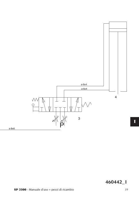
SP 2300 - Manuale d’uso + pezzi di ricambio 19
I
460442_1

Note
20 SP 2300 - Manuale d’uso + pezzi di ricambio
SP 2300 - Operator’s manual + spare parts 21
UK
TABLE OF CONTENTSINTRODUCTION ........................................................................................... 22DESCRIPTION OF THE AVAILABLE UNITS ............................................... 23DESCRIPTION OF COMBINATIONS ........................................................... 23TRANSPORT, STORAGE AND HANDLING ................................................ 25
Machine transporting conditions and technical data ........................ 25Machine transporting and storage environmental conditions ......... 25
SAFETY STANDARDS .................................................................................. 25INSTALLATION ON THE TYRE CHANGER ................................................ 26FUNCTIONAL PARTS ................................................................................... 30
CHECKING CORRECT OPERATION ...................................................... 30USAGE ........................................................................................................... 30
Tyre demounting/mounting .................................................................. 31Approved procedure for demounting and mounting UHP and Run Flat tyres .................................................................................. 34
MAINTENANCE ............................................................................................ 34INFORMATION ON DEMOLITION .............................................................. 35FIREFIGHTING MEANS TO USE ................................................................ 35PNEUMATIC DIAGRAM ............................................................................... 36

22 SP 2300 - Operator’s manual + spare parts
INTRODUCTIONThe purpose of this manual is to furnish the owner and operator of this machine with a set of practical and safe instructions for the use and maintenance of the HELP power unit.Follow all the instructions carefully and your tyre changer will assist you in your work and give lasting and efficient service in keeping with producer. traditions.The following paragraphs define the levels of danger regarding the machine associated with the warning captions found in this manual:DANGERRefers to immediate danger with the risk of serius injury or death.WARNINGDangers or unsafe procedures that can cause serious injury or death.ATTENTIONDangers or unsafe procedures that can cause minor injuries or damage to property.
Read these instructions carefully before po-wering up the machine. Conserve this manual and all illustrative material supplied with the machine in a folder near the tyre changer where it is readily accessible for consultation by the machine operator.The technical documentation supplied is con-sideredanintegralpartofthemachine;intheevent of sale all relative documentation must remain with the jack.The manual is only to be considered valid for the machine of the model and with the serial number indicated on the nameplate carried by the machine.
WARNING
Adhere to the contents of this manual: the pro-ducer declines all liability in the case of uses of the equipment not specifically described in this manual.
NoteSome of the illustrations in this manual have beentakenfromphotographsofprototypes;thestandard production model may differ slightly in certain respects.These instructions are for the attention of persons with basic mechanical skills. We have therefore condensed the descriptions of each operation by omitting detailed instructions regarding, for example, how to loosen or tighten the fixing devices on the machine. Do not attempt to perform operations unless properly qualified and with suitable experience. In case of need, please contact our nearest authorised Service Centre for assistance.

SP 2300 - Operator’s manual + spare parts 23
UK
DESCRIPTION OF AVAILABLE UNITS
Column A2020-2025 ....Cod. 8-11100351(from2005)
Column A210Cod. 8-11100307(up to2004)
Power unitCod. 8-11100310
Mobile arm STDCod. 8-11100309
Mobile arm WDKCod. 8-11100306
Universal rim pressing coneCod. 8-11100311(on request)
DESCRIPTION OF COMBINATIONS
STD Version for A 2020-2025 ...
(from 2005)
Cod. 8-11100351
Cod. 8-11100310
Cod. 8-11100309
24 SP 2300 - Operator’s manual + spare parts
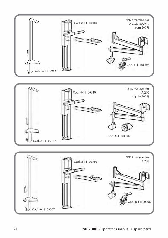
WDK version for A 2020-2025 ...
(from 2005)
STD version for A 210
(up to 2004)
WDK version for A 210
Cod. 8-11100351
Cod. 8-11100310
Cod. 8-11100306
Cod. 8-11100307
Cod. 8-11100310
Cod. 8-11100309
Cod. 8-11100307
Cod. 8-11100310
Cod. 8-11100306
SP 2300 - Operator’s manual + spare parts 25
UK
SAFETY REGULATIONSThe equipment is intended for professional use only.
WARNING
Only one operator may work on the equipment at a time.
WARNING
Failure to observe these instructions and the relative danger warnings can cause serious injury to the operator and others. Do not po-wer up the machine before you have read and understood all the danger/warning/attention notices in this manual.
This machine must be used only by qualified and authorised personnel. A qualified opera-tor is construed as a person who has read and understood the manufacturer’s instructions, is suitably trained, and is conversant with safety and adjustment procedures to be adhered to during operations. Operators are expressly forbidden from using the machine under the influence of alcohol or drugs capable of affecting physical and mental capacity. The following conditions are essential:- The operator must be able to read and under-
stand all the information in this manual.- Make sure you have a thorough knowledge
of the capabilities and characteristics of this machine.
- Keep unauthorised persons well clear of the area of operations.
- Make sure that the machine has been installed in compliance with established legislation and standards.
- Make sure that all machine operators are suita-ble trained, that they are capable of using the machine correctly and that they are adequately supervised during their work.
- Never leave nuts, bolts, tools or other equipment on the machine to avoid the risk that they could become entrapped between moving parts during work.
- Do not touch power lines or the inside of electric motors or other electrical equipment until the power has been disconnected and locked out.
- Read this manual carefully and learn how to use the machine correctly and safely.
- Always keep this user manual in a place where it can be readily consulted when working with
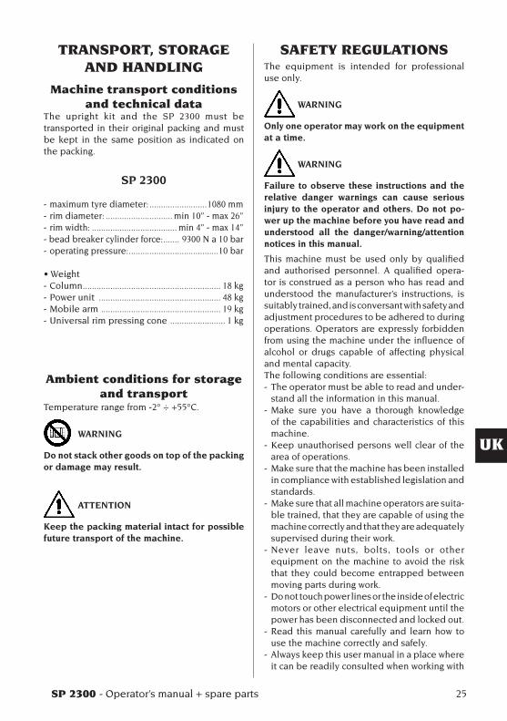
TRANSPORT, STORAGE AND HANDLING
Machine transport conditions and technical data
The upright kit and the SP 2300 must be transported in their original packing and must be kept in the same position as indicated on the packing.
SP 2300
- maximum tyre diameter: .........................1080 mm- rim diameter: ............................. min 10” - max 26”- rim width: ..................................... min 4” - max 14” - bead breaker cylinder force: ....... 9300 N a 10 bar- operating pressure: .......................................10 bar
•Weight- Column ............................................................ 18 kg - Power unit ..................................................... 48 kg- Mobile arm .................................................... 19 kg- Universal rim pressing cone ........................ 1 kg
Ambient conditions for storage and transport
Temperature range from -2° ÷ +55°C.
WARNING
Do not stack other goods on top of the packing or damage may result.
ATTENTION
Keep the packing material intact for possible future transport of the machine.
26 SP 2300 - Operator’s manual + spare parts
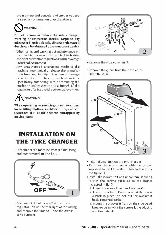
the machine and consult it whenever you are in need of confirmation or explanations.
WARNING
Do not remove or deface the safety Danger, Warning or Instruction decals. Replace any missing or illegible decals. Missing or damaged decals can be obtained at your nearest dealer.
- When using and carrying out maintenance on the machine observe the unified industrial accident prevention regulations for high voltage industrial equipment.
- Any unauthorised alterations made to the machine automatically release the manufac-turer from any liability in the case of damage or accidents attributable to such alterations. Specifically, tampering with or removing the machine’s safety devices is a breach of the regulations for industrial accident prevention.
WARNING
When operating or servicing do not wear ties, loose fitting clothes, necklaces, rings or wri-stwatches that could become entrapped by moving parts.
INSTALLATION ON THE TYRE CHANGER
•Disconnectthemachinefromthemainsfig.1and compressed air line fig. 2.
1
•DisconnecttheairhosesTofthefilter-regulator unit on the rear right of the casing and remove the unit fig. 2 and the grease cone support
T V 2
•Removethesidecoverfig.3;
•Removetheguardfromthebaseofthecolumn,fig.3;
3•Installthecolumnonthetyrechanger•Fix it to the tyre changer with the screws
supplied in the kit, in the points indicated in the figure. 4)
•Installthepowerunitonthecolumn,securingit with the screws supplied in the points indicated in fig. 5:1.InsertthescrewE,nutandwasherG;2. Insert the column F and then put the screw
A back in place (do not put the washer B back,removedearlier);
3. Mount the bracket H fig. 5 on the side bead breaker beam with the screws I, the block L and the nuts M

SP 2300 - Operator’s manual + spare parts 27
UK
4
A
B
E
F
G
HI
L
M
5

28 SP 2300 - Operator’s manual + spare parts
•Installthearmwithbeadbreakerdisconthepowerunitfig.6
6•Fixthemobilearmtothepowerunit(fig.7)
7
•Fixthegreaseconeholdertothepowerunit(fig.8).
•Installthefilter/lubricatorunitonthebackofthepowerunitinthepositionshowninfig.9.
•Fixthebundleofpneumaticpipesleadingfromthemobilearmtothepowerunitusingtheclampssupplied (Fig. 9).
•Connectthe2smalldiameterpneumaticpipestothepowerunitcylinder.Fixthepipeleadingto

SP 2300 - Operator’s manual + spare parts 29
UK
the bottom part with the clamps (fig. 9)
•Usingthepipesandunionssupplied,maketheconnections to the filter-regulator unit as shown in fig. 9.
•Refitthesidecoverandcolumnguard.
•Reconnectthetyrechangertotheelectricalandpneumatic power supplies
9
8
30 SP 2300 - Operator’s manual + spare parts
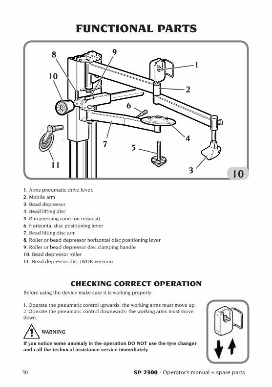
FUNCTIONAL PARTS
10
1
2
4
3
5
6
7
10
98
11
1. Arms pneumatic drive lever.
2. Mobile arm
3. Bead depressor
4. Bead lifting disc
5. Rim pressing cone (on request)
6. Horizontal disc positioning lever
7. Bead lifting disc arm
8. Roller or bead depressor horizontal disc positioning lever
9. Roller or bead depressor disc clamping handle
10. Bead depressor roller
11. Bead depressor disc (WDK version)
CHECKING CORRECT OPERATIONBefore using the device make sure it is working properly:
1. Operate the pneumatic control upwards: the working arms must move up. 2. Operate the pneumatic control downwards: the working arms must move down.
WARNING
If you notice some anomaly in the operation DO NOT use the tyre changer and call the technical assistance service immediately.
SP 2300 - Operator’s manual + spare parts 31
UK
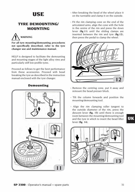
- After breaking the bead of the wheel place it on the turntable and clamp it on the outside.
- Fit the rim clamping cone on the end of the articulated arms, align the cone with the hole in the centre of the rim and press the down lever (fig.11) until the sliding clamps are inserted between the rim and tyre (fig.12), then press the pedal to clamp the wheel.
12- Remove the centring cone, put it away and
remount the bead presser block.
- Tilt the column forwards and position the mounting/demounting tool.
- Align the rim clamping roller tangent to the outside diameter of the rim, press the descent lever (fig. 13) until there is enough room between the mounting/demounting tool and the tyre in which to insert the bead lifter lever (fig. 14).
13
USE
TYRE DEMOUNTING/MOUNTING
WARNING
For all tyre mounting/demounting procedures not specifically described, refer to the tyre changer use and maintenance manual.
HELP is designed to facilitate the demounting and mounting stages of the light alloy rims and particularly stiff low-profile tyres.
Proceed as follows to get the best performance from these accessories. Proceed with bead breaking the tyre as described in the instruction manual enclosed with the tyre changer.
Demounting
11
WDK

32 SP 2300 - Operator’s manual + spare parts
14- remove the bead depressor roller, position
the bead depressor block so it is opposite the mounting/demounting tool, press the down lever so the bead fits inside the rim well (fig.15).
15- Load the bead above the mounting/
demounting tool, move the bead depressor block away, press the rotation pedal and remove the first bead (fig.16).
- Move the bottom bead up to the top edge of therim; insomecases,even if thebead has already been broken, the bottom bead will remain in place because it has stuck to the rim. In these cases, use the disc by inserting it between the bottom bead and
the rim (fig.17), press the rotation pedal and lift.
16
17The second bead can be demounted in the traditional way, with the lever or using the bead depressor roller.- Position the roller tangent to the outside
edge of the rim (fig. 18).
18
WDK
WDK
WDK
WDK
SP 2300 - Operator’s manual + spare parts 33
UK
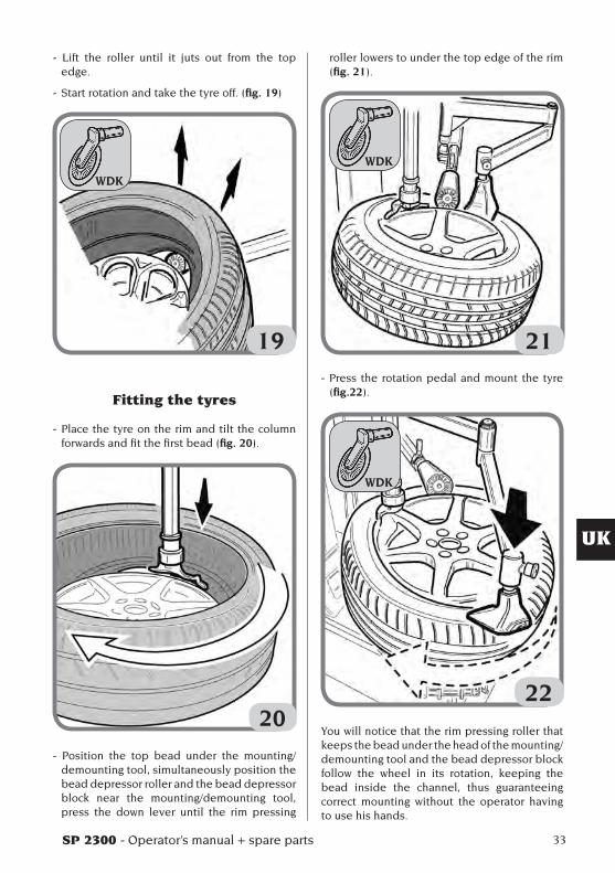
- Lift the roller until it juts out from the top edge.
- Start rotation and take the tyre off. (fig. 19)
19
Fitting the tyres
- Place the tyre on the rim and tilt the column forwards and fit the first bead (fig. 20).
20
- Position the top bead under the mounting/demounting tool, simultaneously position the bead depressor roller and the bead depressor block near the mounting/demounting tool, press the down lever until the rim pressing
roller lowers to under the top edge of the rim (fig. 21).
21- Press the rotation pedal and mount the tyre
(fig.22).
22You will notice that the rim pressing roller that keeps the bead under the head of the mounting/demounting tool and the bead depressor block follow the wheel in its rotation, keeping the bead inside the channel, thus guaranteeing correct mounting without the operator having to use his hands.
WDK
WDK
WDK

34 SP 2300 - Operator’s manual + spare parts
NOTE: stop rotation when the bead depressor is near the mounting/demounting tool.
- Press the lift lever, release the wheel from the roller and bead depressor.
APPROVED M/D PROCEDURE FOR UHP AND RUN FLAT TYRES
For the detailed M/D procedure for UHP and RUN FLAT tyres, please refer to the instruction manual wrote by WDK (German Association of the Tyre Industry)
MAINTENANCE
WARNINGThe producer declines all liability for claims deriving from the use of non-original spares or accessories.
WARNINGBefore making any adjustments or carrying out maintenance, disconnect the electrical supply from the machine and make sure that all moving parts are suitable immobilised.
WARNINGDo not remove or modify any parts of this ma-chine except in the case of service interventions.
DANGERBefore carrying out any maintenance operation or topping up with lubricant, disconnect the machine from the compressed air supply line.
ATTENTIONKeep the work area clean.Do not clean the machine with compressed air or jets of water.When cleaning the area avoid raising dust as far as possible.
SP 2300 - Operator’s manual + spare parts 35
UK
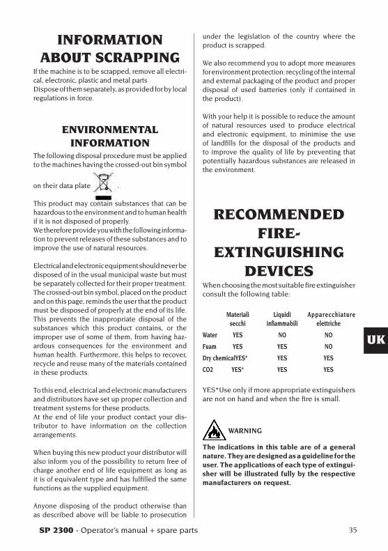
INFORMATION ABOUT SCRAPPING
If the machine is to be scrapped, remove all electri-cal, electronic, plastic and metal partsDispose of them separately, as provided for by local regulations in force.
ENVIRONMENTAL INFORMATION
The following disposal procedure must be applied to the machines having the crossed-out bin symbol
on their data plate .
This product may contain substances that can be hazardous to the environment and to human health if it is not disposed of properly.We therefore provide you with the following informa-tion to prevent releases of these substances and to improve the use of natural resources.
Electrical and electronic equipment should never be disposed of in the usual municipal waste but must be separately collected for their proper treatment.The crossed-out bin symbol, placed on the product and on this page, reminds the user that the product must be disposed of properly at the end of its life.This prevents the inappropriate disposal of the substances which this product contains, or the improper use of some of them, from having haz-ardous consequences for the environment and human health. Furthermore, this helps to recover, recycle and reuse many of the materials contained in these products.
To this end, electrical and electronic manufacturers and distributors have set up proper collection and treatment systems for these products.At the end of life your product contact your dis-tributor to have information on the collection arrangements.
When buying this new product your distributor will also inform you of the possibility to return free of charge another end of life equipment as long as it is of equivalent type and has fulfilled the same functions as the supplied equipment.
Anyone disposing of the product otherwise than as described above will be liable to prosecution
under the legislation of the country where the product is scrapped.
We also recommend you to adopt more measures for environment protection: recycling of the internal and external packaging of the product and proper disposal of used batteries (only if contained in the product).
With your help it is possible to reduce the amount of natural resources used to produce electrical and electronic equipment, to minimise the use of landfills for the disposal of the products and to improve the quality of life by preventing that potentially hazardous substances are released in the environment.
RECOMMENDED FIRE-
EXTINGUISHING DEVICES
When choosing the most suitable fire extinguisher consult the following table:
Materiali Liquidi Apparecchiature secchi infiammabili elettriche
Water YES NO NO
Fuam YES YES NO
Dry chemical YES* YES YES
CO2 YES* YES YES
YES*Use only if more appropriate extinguishers are not on hand and when the fire is small.
WARNING
The indications in this table are of a general nature. They are designed as a guideline for the user. The applications of each type of extingui-sher will be illustrated fully by the respective manufacturers on request.
36 SP 2300 - Operator’s manual + spare parts
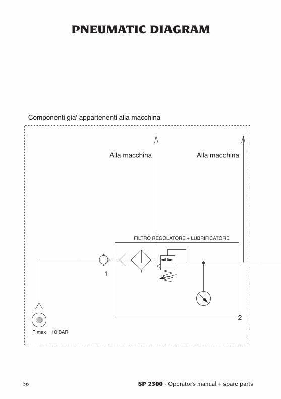
PNEUMATIC DIAGRAM

SP 2300 - Operator’s manual + spare parts 37
UK
460442_1

Note
38 SP 2300 - Operator’s manual + spare parts

SP 2300 - Manuel d’utilisation + rechange 39
F
SOMMAIREINTRODUCTION ........................................................................................... 40DESCRIPTION DES GROUPES DISPONIBLES .......................................... 41DESCRIPTION DES COMBINAISONS ........................................................ 41TRANSPORT, STOCKAGE ET MANUTENTION ......................................... 43
Conditions de transport de la machine et données techniques ..... 43Conditions environnementales de transport et de stockage de la machine ......................................................................................... 43
NORMES DE SECURITE .............................................................................. 43INSTALLATION SUR LE DEMONTE-PNEUS ............................................. 44PARTIES FONCTIONNELLES ...................................................................... 48
CONTROLE FONCTIONNEL.................................................................. 48UTILISATION ................................................................................................. 49
Démontage/Montage du pneu ............................................................. 49Procédure homologuée de démontage et montage des pneus UHP et Run Flat ...................................................................................... 52
ENTRETIEN .................................................................................................. 52INFORMATIONS CONCERNANT LA DEMOLITION ................................. 53MESURES ANTI-INCENDIE ......................................................................... 53SCHEMA PNEUMATIQUE ............................................................................ 54

40 SP 2300 - Manuel d’utilisation + rechange
INTRODUCTIONCette publication fournit au propriétaire et à l’opérateur les instructions efficaces et sûres, concernant l’utilisation et l’entretien de l’unité de puissace HELP.Si ces instructions sont scrupuleusement re-spectées, votre machine vous donnera toutes les satisfactions d’efficacité et de durée qui font partie de la tradition du producteur, en contri-buant à faciliter considérablement votre travail.Ci-après sont fournies les définitions permettant d’identifier les niveaux de danger, ainsi que les signalisations utilisées dans ce manuel:
DANGERDangers immédiats provoquant de graves blessures ou la mort.
ATTENTIONDangers ou procédures à risques pouvant pro-voquer de graves blessures ou la mort.
AVERTISSEMENTDangers ou procédures à risques pouvant pro-voquer de légères blessures ou des dommages matériels.
Lire attentivement ces instructions avant de faire fonctionner l’appareil. Conserver ce manuel, ainsi que le reste du matériel illustratif fourni avec l’appareil, dans une pochette près de la machine, afin que les opérateurs puissent facilement le consulter à tout moment.La documentation technique fournie, fait partie intégrante de l’appareil et doit donc, en cas de vente, toujours accompagner ce dernier.Le manuel n’est valable que pour le modèle et la série de la machine qui sont reportés sur la plaquette appliquée sur celle-ci.
ATTENTION
Respecter scrupuleusement les instructions fournies dans ce manuel: toute autre utilisation ne figurant pas dans ce dernier est sous l’entière responsabilité de l’opérateur.
REMARQUECertaines illustrations figurant dans ce manuel ont été faites à partir de photos de prototypes: les machines de la production standard peuvent être différentes pour certaines pièces.Ces instructions sont destinées à des personnes ayant de bonnes connaissances mécaniques. Chaque opération n’a donc pas été décrite, comme par exemple la manière de desserrer ou de serrer les dispositifs de fixation. Il faut éviter d’effectuer des opérations trop compliquées à exécuter ou pour lesquelles vous n’avez pas assez d’expérience. Il est vivement conseillé à l’opérateur de faire appel à un centre d’assi-stance autorisé.

SP 2300 - Manuel d’utilisation + rechange 41
F
DESCRIPTION DES GROUPES DISPONIBLES
Montant A2020-2025 ....Réf. 8-11100351(après le2004)
Montant A210Réf. 8-11100307(avant de2004)
Unité de puissanceRéf. 8-11100310
Bras mobile STDRéf. 8-11100309
Bras mobile WDKRéf. 8-11100306
Cône presse-jante universel Réf. 8-11100311(en option))
DESCRIPTION DES COMBINAISONS
Version STD pour A 2020-2025 ...(après le 2004)
Réf. 8-11100351
Réf. 8-11100310
Réf. 8-11100309
42 SP 2300 - Manuel d’utilisation + rechange
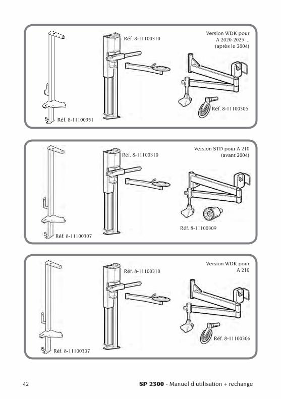
Version WDK pour A 2020-2025 ...(après le 2004)
Version STD pour A 210 (avant 2004)
Version WDK pour A 210
Réf. 8-11100351
Réf. 8-11100310
Réf. 8-11100306
Réf. 8-11100307
Réf. 8-11100310
Réf. 8-11100309
Réf. 8-11100307
Réf. 8-11100310
Réf. 8-11100306
SP 2300 - Manuel d’utilisation + rechange 43
F
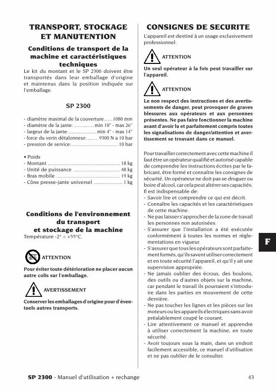
CONSIGNES DE SECURITEL’appareil est destiné à un usage exclusivement professionnel.
ATTENTION
Un seul opérateur à la fois peut travailler sur l’appareil.
ATTENTION
Le non respect des instructions et des avertis-sements de danger, peut provoquer de graves blessures aux opérateurs et aux personnes présentes. Ne pas faire fonctionner la machine avant d’avoir lu et parfaitement compris toutes les signalisations de danger/attention et aver-tissement se trouvant dans ce manuel.
Pour travailler correctement avec cette machine il faut être un opérateur qualifié et autorisé capable de comprendre les instructions écrites par le fa-bricant, être formé et connaître les consignes de sécurité. Un opérateur ne doit pas se droguer ou boire d’alcool, car cela peut altérer ses capacités.Il est indispensable de:- Savoir lire et comprendre ce qui est décrit.- Connaître les capacités et les caractéristiques
de cette machine.- Ne pas laisser s’approcher de la zone de travail
les personnes non autorisées.- S’assurer que l’installation a été exécutée
conformément à toutes les normes et régle-mentations en vigueur.
- S’assurer que tous les opérateurs sont parfaite-ment formés, qu’ils savent utiliser correctement et en toute sécurité l’appareil, et qu’il y ait une supervision appropriée.
- Ne jamais oublier des écrous, des boulons, des outils ou d’autres objets sur la machine, car pendant le travail ils pourraient s’introdu-ire dans les parties en mouvement de cette dernière.
- Ne pas toucher les lignes et les pièces sur les moteurs ou les appareils électriques sans avoir préalablement coupé le courant.
- Lire attentivement ce manuel et apprendre à utiliser correctement la machine, en toute sécurité.
- Avoir toujours sous la main, dans un endroit facilement accessible, ce manuel d’utilisation et ne pas oublier de le consulter.
TRANSPORT, STOCKAGE ET MANUTENTION
Conditions de transport de la machine et caractéristiques
techniquesLe kit du montant et le SP 2300 doivent être transportés dans leur emballage d'origine et maintenus dans la position indiquée sur l'emballage.
SP 2300
- diamètre maximal de la couverture .......1080 mm- diamètre de la jante: ................ min 10” - max 26”- largeur de la jante: ...................... min 4” - max 14” - force du verin détalonneur: ........ 9300 N a 10 bar- pression de service: ......................................10 bar
•Poids- Montant .......................................................... 18 kg - Unité de puissance ..................................... 48 kg- Bras mobile ................................................... 19 kg- Cône presse-jante universel ....................... 1 kg
Conditions de l’environnement du transport
et stockage de la machineTempérature -2° ÷ +55°C.
ATTENTION
Pour éviter toute détérioration ne placer aucun autre colis sur l’emballage.
AVERTISSEMENT
Conserver les emballages d’origine pour d’éven-tuels autres transports.
44 SP 2300 - Manuel d’utilisation + rechange
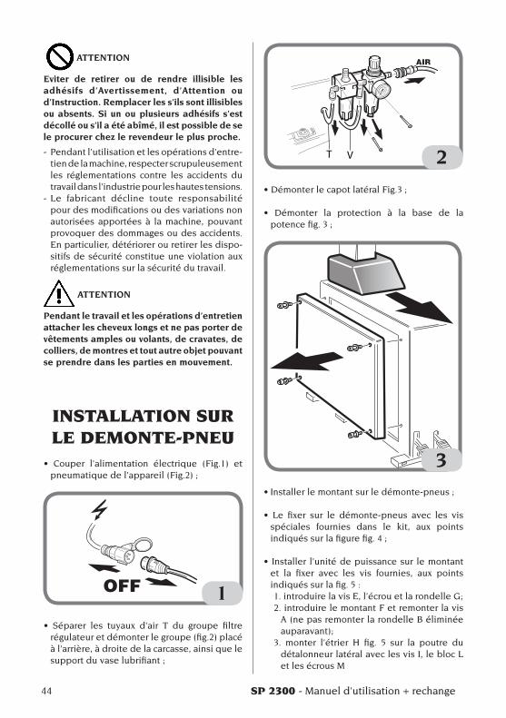
ATTENTION
Eviter de retirer ou de rendre illisible les adhésifs d’Avertissement, d’Attention ou d’Instruction. Remplacer les s’ils sont illisibles ou absents. Si un ou plusieurs adhésifs s’est décollé ou s’il a été abîmé, il est possible de se le procurer chez le revendeur le plus proche.
- Pendant l’utilisation et les opérations d’entre-tien de la machine, respecter scrupuleusement les réglementations contre les accidents du travail dans l’industrie pour les hautes tensions.
- Le fabricant décline toute responsabilité pour des modifications ou des variations non autorisées apportées à la machine, pouvant provoquer des dommages ou des accidents. En particulier, détériorer ou retirer les dispo-sitifs de sécurité constitue une violation aux réglementations sur la sécurité du travail.
ATTENTION
Pendant le travail et les opérations d’entretien attacher les cheveux longs et ne pas porter de vêtements amples ou volants, de cravates, de colliers, de montres et tout autre objet pouvant se prendre dans les parties en mouvement.
INSTALLATION SUR LE DEMONTE-PNEU
• Couper l’alimentation électrique (Fig.1) etpneumatiquedel’appareil(Fig.2);
1
• Séparer les tuyaux d’air T du groupe filtrerégulateur et démonter le groupe (fig.2) placé à l’arrière, à droite de la carcasse, ainsi que le supportduvaselubrifiant;
T V 2
•DémonterlecapotlatéralFig.3;
• Démonter la protection à la base de lapotencefig.3;
3•Installerlemontantsurledémonte-pneus;
• Le fixer sur le démonte-pneus avec les visspéciales fournies dans le kit, aux points indiquéssurlafigurefig.4;
• Installer l’unitédepuissancesur lemontant
et la fixer avec les vis fournies, aux points indiqués sur la fig. 5 :1.introduirelavisE,l’écrouetlarondelleG;2. introduire le montant F et remonter la vis
A (ne pas remonter la rondelle B éliminée auparavant);
3. monter l’étrier H fig. 5 sur la poutre du détalonneur latéral avec les vis I, le bloc L et les écrous M

SP 2300 - Manuel d’utilisation + rechange 45
F
4
A
B
E
F
G
HI
L
M
5

46 SP 2300 - Manuel d’utilisation + rechange
•Installerlebrasàdisquedétalonneursurl’unitédepuissancefig.6;
6
•Fixerlebrasmobilesurl’unitédepuissance(fig.7);
7
•Fixerlesupportduvaselubrifiantsurl’unitédepuissance(fig.8);
•Installerlegroupefiltre/lubrificateuràl’arrièredel’unitédepuissance,surlapositionindiquéefig.9;
•Fixerlefaisceaudetuyauxpneumatiquesquiressortdubrasmobilesurl’unitédepuissance,aveclecollierfourni(Fig.9);
•Raccorder les2tuyauxpneumatiquesdepetitdiamètreauvérindel’unitédepuissance.Fixer le

SP 2300 - Manuel d’utilisation + rechange 47
F
tuyau allant vers la partie inférieure par les colliersprévus(fig.9);
• Utiliser les tuyaux et les raccords fournis pourprocéder aux branchements au groupe filtre/régulateur,commemontrésurlafig.9;
•Remonterlecapotlatéraletleprotège-potence;
• Rebrancher le démonte-pneus à l’alimentationélectrique et pneumatique.
9
8
48 SP 2300 - Manuel d’utilisation + rechange
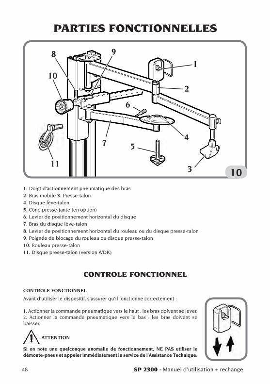
PARTIES FONCTIONNELLES
10
1
2
4
3
5
6
7
10
98
11
1. Doigt d’actionnement pneumatique des bras
2. Bras mobile 3. Presse-talon
4. Disque lève-talon
5. Cône presse-jante (en option)
6. Levier de positionnement horizontal du disque
7. Bras du disque lève-talon
8. Levier de positionnement horizontal du rouleau ou du disque presse-talon
9. Poignée de blocage du rouleau ou disque presse-talon
10. Rouleau presse-talon
11. Disque presse-talon (version WDK)
CONTROLE FONCTIONNEL
CONTROLE FONCTIONNEL
Avant d’utiliser le dispositif, s’assurer qu’il fonctionne correctement :
1. Actionner la commande pneumatique vers le haut : les bras doivent se lever. 2. Actionner la commande pneumatique vers le bas : les bras doivent se baisser.
ATTENTION
Si on note une quelconque anomalie de fonctionnement, NE PAS utiliser le démonte-pneus et appeler immédiatement le service de l’Assistance Technique.
SP 2300 - Manuel d’utilisation + rechange 49
F
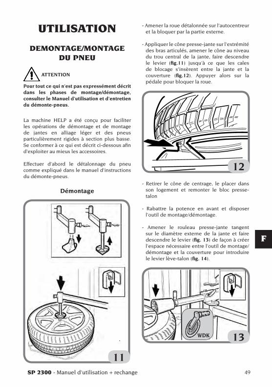
- Amener la roue détalonnée sur l’autocentreur et la bloquer par la partie externe.
- Appliquer le cône presse-jante sur l’extrémité des bras articulés, amener le cône au niveau du trou central de la jante, faire descendre le levier (fig.11) jusqu’à ce que les cales de blocage s’insèrent entre la jante et la couverture (fig.12). Appuyer alors sur la pédale pour bloquer la roue.
12- Retirer le cône de centrage, le placer dans
son logement et remonter le bloc presse-talon
- Rabattre la potence en avant et disposer l’outil de montage/démontage.
- Amener le rouleau presse-jante tangent sur le diamètre externe de la jante et faire descendre le levier (fig. 13) de façon à créer l’espace nécessaire entre l’outil de montage/démontage et la couverture pour introduire le levier lève-talon (fig. 14).
13
UTILISATION
DEMONTAGE/MONTAGE DU PNEU
ATTENTION
Pour tout ce qui n’est pas expressément décrit dans les phases de montage/démontage, consulter le Manuel d’utilisation et d’entretien du démonte-pneus.
La machine HELP a été conçu pour faciliter les opérations de démontage et de montage de jantes en alliage léger et des pneus particulièrement rigides à section plus basse. Se conformer à ce qui est décrit ci-dessous afin d’exploiter au mieux les accessoires.
Effectuer d’abord le détalonnage du pneu comme expliqué dans le manuel d’instructions du démonte-pneus.
Démontage
11
WDK
50 SP 2300 - Manuel d’utilisation + rechange
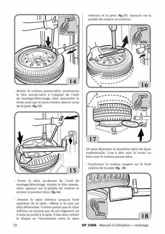
14- Retirer le rouleau presse-talon, positionner
le bloc presse-talon à l’opposé de l’outil de montage/démontage, faire descendre le levier pour que le talon s’insère dans le creux de la jante (fig.15).
15- Porter le talon au-dessus de l’outil de
montage/démontage, écarter le bloc presse-talon, appuyer sur la pédale de rotation et extraire le premier talon (fig.16).
- Amener le talon inférieur jusqu’au bord supérieur de la jante ; Même si la roue estdéjà détalonnée, il arrive parfois que le talon inférieur ne s’écarte pas de son logement car il reste accroché à la jante. Il faut alors utiliser le disque en l’introduisant entre le talon
inférieur et la jante (fig.17). Appuyer sur la pédale de rotation et soulever.
16
17On peut démonter le deuxième talon de façon traditionnelle, c’est à dire avec le levier, ou bien avec le rouleau presse-talon.
- Positionner le rouleau tangent sur le bord externe de la jante (fig. 18).
18
WDK
WDK
WDK
WDK
SP 2300 - Manuel d’utilisation + rechange 51
F
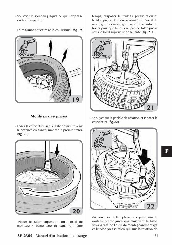
- Soulever le rouleau jusqu’à ce qu’il dépasse du bord supérieur.
- Faire tourner et extraire la couverture. (fig.19)
19
Montage des pneus
- Poser la couverture sur la jante et faire revenir lapotenceenavant;monterlepremiertalon(fig. 20).
20
- Placer le talon supérieur sous l’outil de montage / démontage et dans le même
temps, disposer le rouleau presse-talon et le bloc presse-talon à proximité de l’outil de montage / démontage. Faire descendre le levier pour que le rouleau presse-talon passe sous le bord supérieur de la jante (fig. 21).
21- Appuyer sur la pédale de rotation et monter la
couverture (fig.22).
22 Au cours de cette phase, on peut voir le
rouleau presse-jante qui maintient le talon sous la tête de l’outil de montage/démontage et le bloc presse-talon qui suit la rotation de
WDK WDK
WDK

52 SP 2300 - Manuel d’utilisation + rechange
la roue en maintenant le talon dans le creux. De cette façon, le montage est garanti sans que l’opérateur n’utilise ses mains.
REMARQUE : arrêter la rotation quand le presse-talon se trouve à proximité de l’outil de montage/démontage
- Remonter le levier, libérer la roue du rouleau et du presse-talon.
PROCÉDURE AGRÉÉE POUR LE MONTAGE ET
DÉMONTAGE DES PNEUS UHP ET RUN FLAT
Pour la procédure détaillée de montage et démontage pour pneus UHP et Run Flat, voir le manuel des instructions écrit par WDK (As-sociation Allemande de l’Industrie des Pneus)
ENTRETIEN
ATTENTION
Le producteur décline toute responsabilité pour des réclamations découlant de l’utili-sation de pièces détachées ou d’accessoires non conformes.
ATTENTION
Avant tout réglage ou entretien, débrancher l’alimentation électrique et pneumatique de la machine, et s’assurer que toutes les parties mobiles sont bloquées.
ATTENTION
Ne pas retirer ou modifier certains composants de cette machine (sauf pour des réparations).
DANGER
Avant toute opération d’entretien ou rajout de lubrifiant, interrompre l’alimentation pneuma-tique de la machine.
AVERTISSEMENT
Laisser toujours propre la zone de travail.Ne jamais utiliser d’air comprimé, de jets d’eau ou des diluants pour retirer la saleté ou des résidus sur la machine.Lors des nettoyages, procéder de manière à éviter, lorsque cela est possible, que ne se forme ou ne se soulève la poussière.
INFORMATIONS CONCERNANT
LA DEMOLITIONEn cas de démolition de la machine, séparer les pièces électriques, électroniques, en plas-tique et en fer.Mettre au rebut les différents matériaux confor-mément aux normes en vigueur.
SP 2300 - Manuel d’utilisation + rechange 53
F
MISE AU REBUT DE L’APPAREIL
La procédure décrite dans ce paragraphe n’est applicable qu’aux appareils dont la plaquette d’identification reporte le pictogramme de la benne barrée signifiant qu’en fin de vie, ils doivent être traités de façon particulière
.
Ces appareils contiennent en effet des subs-tances nocives, nuisibles à l’homme et à l’envi-ronnement en cas de traitement impropre.Ce paragraphe fournit donc les règles à respec-ter pour une mise au rebut conforme.
Les appareils électriques et électroniques ne doivent pas être traités comme des déchets ménagers, mais doivent impérativement être acheminés vers un centre de tri sélectif qui se chargera de leur retraitement.Le symbole de la poubelle barrée apposé sur le produit et illustré ci-contre, indique la néces-sité de procéder à l’élimination particularisée du produit au terme de sa vie.De la sorte, il est possible d’éviter qu’un traitement non approprié des substances qu’il contient ou qu’un traitement incorrect d’une partie de celles-ci puisse avoir des conséquences graves sur l’environnement et la santé de l’homme. Une gestion correcte du produit en fin de vie permet de participer à la récupération, au recyclage et à la réutilisation de la plupart des matériaux entrant dans sa composition.
Dans cette optique, les fabricants et les ven-deurs d’appareillages électriques et élec-troniques ont mis en place des systèmes de collecte et de retraitement desdits appareils.S’adresser donc à son propre vendeur pour se renseigner sur le mode de collecte du produit.
Lors de l’achat de cet appareil, le vendeur est tenu de vous informer de la possibilité de rendre gratuitement un appareil usé de même type.
Le non-respect des règles susdites expose le contrevenant aux sanctions prévues par la
législation locale en vigueur en matière de traitement des déchets industriels.
Nous vous invitons en outre à adopter d’autres mesures de protection de l’environnement notamment, recycler correctement l’emballage interne et externe et supprimer correctement les éventuelles piles déchargées (seulement si elles sont contenues dans le produit).
Avec la contribution de chacun, il sera pos-sible de réduire la quantité de ressources naturelles nécessaires à la fabrication des appareils électriques et électroniques, d’opti-miser l’exploitation des déchetteries et d’amé-liorer la qualité de la vie, en évitant que des substances potentiellement dangereuses ne souillent la nature.
MOYENS A UTILISER CONTRE LES INCENDIES
Pour choisir l’extincteur le plus approprié consulter le tableau suivant:
Matériaux Liquides Appareils secs infiammables électriques
Hidrique YES NO NO
Mousse YES YES NO
Poudre YES* YES YES
CO2 YES* YES YES
OUI* Peut être utilisé en l’absance de moyens appropriés ou pour de petits incendies.
ATTENTION
Les indications fournies sur ce tableau ont un caractère général et sont destinées à aider les utilisateurs. Les possibilités d’utilisation de chaque type d’extincteur doivent être demandées au fabricant.
54 SP 2300 - Manuel d’utilisation + rechange
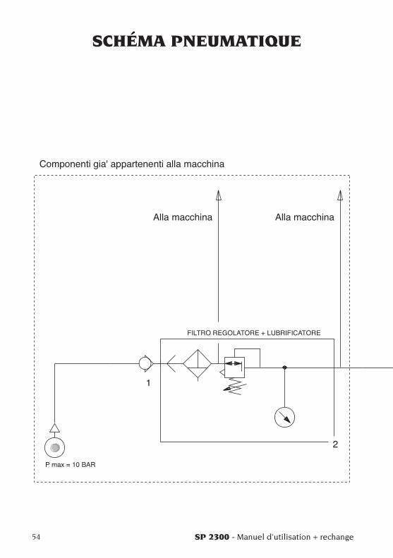
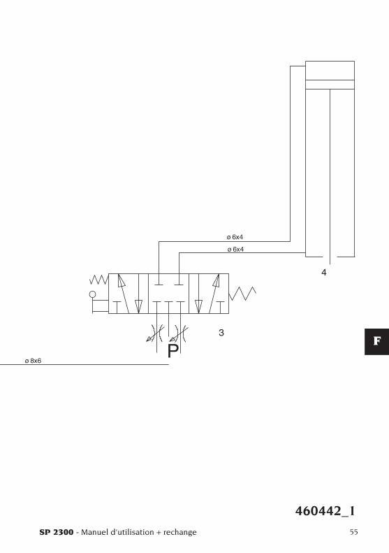
SCHÉMA PNEUMATIQUE
SP 2300 - Manuel d’utilisation + rechange 55
F
460442_1

Note
56 SP 2300 - Manuel d’utilisation + rechange
SP 2300 - Betriebsanleitung + Ersatzteillisten 57
D
INHALTEINFÜHRUNG .............................................................................................. 58BESCHREIBUNG DER LIEFERBAREN GRUPPEN .................................... 59BESCHREIBUNG DER KOMBINATIONEN ................................................ 59TRANSPORT, LAGERUNG UND HANDLING ............................................ 61
Transportbedingungen der Maschine und technische Daten .......... 61Bedingungen für die Transport- und Lagerumgebung der Maschine . 61
SICHERHEITSVORSCHRIFTEN .................................................................. 61INSTALLATION AN DER REIFENMONTIERMASCHINE .......................... 62FUNKTIONSTEILE ....................................................................................... 66KONTROLLE DES KORREKTEN BETRIEBS ............................................. 66EINSATZ ........................................................................................................ 67
Demontage/Montage des Reifens ........................................................ 67Anerkanntes Demontage- und Montageverfahren für UHP- und Run Flat-Reifen ............................................................... 70
WARTUNG ..................................................................................................... 70INFORMATIONEN ZUR ENTSORGUNG DER MASCHINE ....................... 71BRANDSCHUTZMITTEL .............................................................................. 71PNEUMATIKSCHEMA .................................................................................. 72
58 SP 2300 - Betriebsanleitung + Ersatzteillisten
EINLEITUNGDie Bedienungs- und Wartungsanleitungen in diesem Handbuch sollen den Besitzer und An-wender über den zweckgerechten und sicheren Umgang mit der Leistungseinheit SP 2300. Damit Ihre Maschine die bewährten Eigen-schaften an Lebensdauer und Leistungen des Herstellers erbringen und Ihnen dadurch die Arbeit erleichtern kann, müssen die geschil-derten Anweisungen genauestens befolgt werden.Es folgt nun die Aufschlüsselung der einzelnen Gefahrenstufen, die in vorliegendem Handbuch wie folgt gekennzeichnet sind:
GEFAHRUnmittelbare Gefahren, die schwere Verlet-zungen oder tödliche Folgen mit sich bringen.
ACHTUNGGefahren oder sicherheitsmangelnde Vorgän-ge, die schwere Verletzungen bzw. tödliche Folgen mit sich bringen.
WARNUNGGefahren oder sicherheitsmangelnde Vorgän-ge, die leichte Verletzungen oder Material-schäden mit sich bringen.
Die Maschine darf erst nach sorgfältigem Lesen dieser Anleitungen in Betrieb gesetzt werden. Das Handbuch mitsamt dem beigepackten Bildmaterial ist in einer Dokumententasche griffbereit an der Maschine aufzubewahren.Die mitgelieferte technische Dokumentation ist integrierender Bestandteil der Maschine und muß dieser bei Verkauf beigefügt werden.Das Handbuch hat nur für das Modell und die Seriennummer, die auf dem daran angebrachten Schild stehen, Gültigkeit.
ACHTUNG
Die Vorgaben des Handbuchs strikt befolgen, der Hersteller übernimmt keinerlei Haftung bei bestimmungsfremden, nicht ausdrücklich beschriebenen Einsätzen der Maschine.
MerkeEinige Abbildungen vorliegenden Handbuchs entstammen Prototypen, die zum Teil von den Serienmaschinen abweichen können.Es sei auch darauf hingewiesen, daß die Anleitun-gen auf Personal mit gewissen Vorkenntnissen der Mechanik zugeschnitten sind und somit Arbeiten, wie zum Beispiel das Lockern oder Anziehen von Fixiervorrichtungen, nicht beschreiben. Bei der Ausführung von Eingriffen, die über den persönlichen Wissensstand hinausgehen, sollte man nicht eigenmächtig handeln, sondern Rat und Hilfe der zuständigen Servicestelle einholen.
SP 2300 - Betriebsanleitung + Ersatzteillisten 59
D
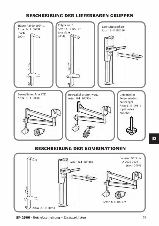
BESCHREIBUNG DER LIEFERBAREN GRUPPEN
Träger A2020-2025 ....Artnr. 8-11100351(nach2004)
Träger A210Artnr. 8-11100307(vor dem2004)
Leistungseinheit Artnr. 8-11100310
Beweglicher Arm STDArtnr. 8-11100309
Beweglicher Arm WDKArtnr. 8-11100306
Universeller Felgennieder-haltekegel Artnr. 8-11100311(optionales Zubehör)
BESCHREIBUNG DER KOMBINATIONEN
Version STD für A 2020-2025 ...
(nach 2004)
Artnr. 8-11100351
Artnr. 8-11100310
Artnr. 8-11100309
60 SP 2300 - Betriebsanleitung + Ersatzteillisten
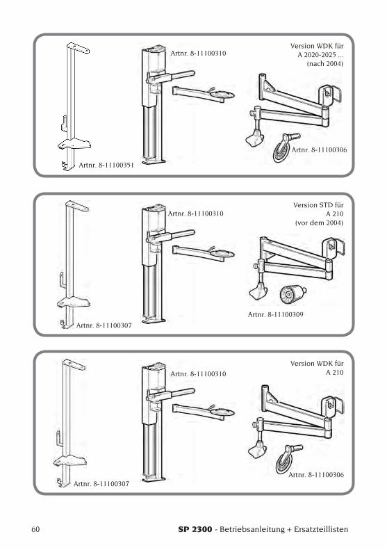
Version WDK für A 2020-2025 ...
(nach 2004)
Version STD für A 210
(vor dem 2004)
Version WDK für A 210
Artnr. 8-11100351
Artnr. 8-11100310
Artnr. 8-11100306
Artnr. 8-11100307
Artnr. 8-11100310
Artnr. 8-11100309
Artnr. 8-11100307
Artnr. 8-11100310
Artnr. 8-11100306
SP 2300 - Betriebsanleitung + Ersatzteillisten 61
D
SICHERHEITS-VORSCHRIFTEN
Die Maschine ist ausschließlich für professionelle Anwendungen vorgesehen.
ACHTUNG
Die Maschine darf stets nur von einem Anwender bedient werden.
ACHTUNG
Die Nichtbeachtung der Anleitungen und Ge-fahrenhinweise kann zu schweren Verletzungen für Bedien- und umstehende Personen führen. Die Maschine darf erst nach sorgfältigem Lesen und eingehender Kenntnis aller Gefahren-/Warnhinweise dieses Handbuchs in Betrieb gesetzt werden.
Der ordnungsgemäße Betrieb der Maschine ist ausschließlich dem zuständigen Fachpersonal vorbehalten. Als solches muß man mit den Herstellervorschriften vertraut sein, die geei-gnete Ausbildung durchlaufen haben und die sicherheitstechnischen Berufsregeln kennen.Es ist jedoch unerläßlich, nachstehende Hinweise zu beachten:- Die Anleitungen gewissenhaft studieren und
danach handeln.- Die Leistungen und Eigenschaften dieser Ma-
schine kennen.- Fremde Personen vom Arbeitsbereich fernhal-
ten.- Sich von der normgerechten Aufstellung und
Installation der Maschine überzeugen.- Sich davon vergewissern, daß das gesamte
Bedienpersonal für die richtige und sichere Bedienung der Maschine geschult ist und hierüber Aufsicht geführt wird.
- Schraubteile, Werkzeuge oder andere Gegen-stände unbedingt von der Maschine entfernen, damit sie bei der Arbeit nicht in die Bewegung-steile gelangen.
- Erst nachdem man absolut sicher ist, daß die Maschine spannungslos steht, dürfen Stromlei-tungen oder elektrische Geräte berührt und es darf in E-Motoren gegriffen werden.
- Dieses Handbuch aufmerksam durchlesen und den Maschinenbetrieb unter kompletter Sicherheit erlernen.
- Dieses Handbuch griffbereit halten und es bei Bedarf stets konsultieren.
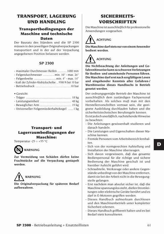
TRANSPORT, LAGERUNG UND HANDLING
Transportbedingungen der Maschine und technische
DatenDer Bausatz des Ständers und die SP 2300 müssen in den jeweiligen Originalverpackungen transportiert und in der auf der Verpackung angegebenen Position belassen werden.
SP 2300
- maximaler Durchmesser Reifen .............1080 mm- Felgendurchmesser ............... min. 10” - max. 26”- Felgenbreite ............................. min. 4” - max. 14” - Kraft der Zylinder-Abdrückscheibe ... 9300 N bei 10 bar- Betriebsdruck ...............................................10 bar
•Gewicht: - Träger ............................................................. 18 kg - Leistungseinheit .......................................... 48 kg- Beweglicher Arm .......................................... 19 kg- Universeller Felgenniederhaltekegel ...... 1 kg
Transport- und Lagerraumbedingungen der
Maschine:Temperatur -25 ÷ +55 °C
WARNUNG
Zur Vermeidung von Schäden dürfen keine Frachtstücke auf die Verpackung gestapelt werden.
WARNUNG
Die Originalverpackung für späteren Bedarf aufbewahren.
62 SP 2300 - Betriebsanleitung + Ersatzteillisten
ACHTUNG
Die Aufkleber mit den Warn-, Vorsichts- und Betriebshinweisen dürfen nicht unkenntlich ge-macht werden. Derartige bzw. fehlende Aufkle-ber umgehend nachrüsten. Sollten Aufkleber gelöst oder beschädigt sein, können Sie diese beim nächstgelegenen Händler anfordern.- Bei Betrieb und Wartungsarbeiten sind die für
Hochspannung geltenden einheitlichen Unfall-schutzvorschriften genauestens zu befolgen.
- Im Falle eigenmächtiger Umrüstungen oder Änderungen der Maschine ist der Hersteller jeglicher Haftpflicht für Schäden oder Fol-geunfälle entbunden. Im besonderen gilt das Verstellen und Abnehmen der Schutzvor-richtungen als Verstoß gegen die Normen zur Arbeitssicherheit.
ACHTUNG
Bei Betrieb und Wartungsarbeiten lange Haare zusammenbinden, keine weite und lose Klei-dung tragen sowie Schlipse, Ketten, Armban-duhren und von Bewegungsteilen mitreißbare Gegenstände ablegen
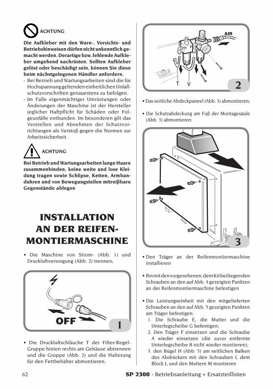
INSTALLATION AN DER REIFEN-
MONTIERMASCHINE• Die Maschine von Strom- (Abb. 1) und
Druckluftversorgung(Abb.2)trennen;
1
• Die Druckluftschläuche T der Filter-Regel-Gruppe hinten rechts am Gehäuse abtrennen und die Gruppe (Abb. 2) und die Halterung fürdenFettbehälterabmontieren;
T V 2•DasseitlicheAbdeckpaneel(Abb.3)abmontieren;
•DieSchutzabdeckungamFußderMontagesäule(Abb.3)abmontieren;
3•Den Träger an der Reifenmontiermaschine
installieren
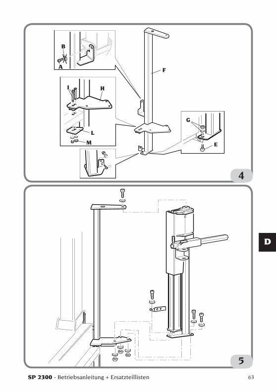
•Ihnmitdenvorgesehenen,demKitbeiliegendenSchrauben an den auf Abb. 4 gezeigten Punkten an der Reifenmontiermaschine befestigen
•Die Leistungseinheit mit den mitgeliefertenSchrauben an den auf Abb. 5 gezeigten Punkten am Träger befestigen:1. Die Schraube E, die Mutter und die
UnterlegscheibeGbefestigen;2. Den Träger F einsetzen und die Schraube
A wieder einsetzen (die zuvor entfernte UnterlegscheibeBnichtwiedermontieren);
3. den Bügel H (Abb. 5) am seitlichen Balken des Abdrückers mit den Schrauben I, dem Block L und den Muttern M montieren
SP 2300 - Betriebsanleitung + Ersatzteillisten 63
D
4
A
B
E
F
G
HI
L
M
5
64 SP 2300 - Betriebsanleitung + Ersatzteillisten
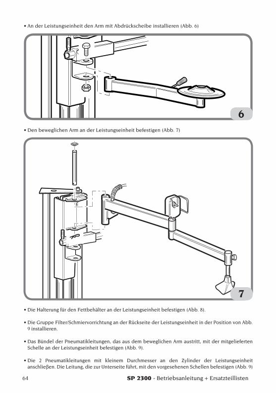
•AnderLeistungseinheitdenArmmitAbdrückscheibeinstallieren(Abb.6)
6•DenbeweglichenArmanderLeistungseinheitbefestigen(Abb.7)
7•DieHalterungfürdenFettbehälteranderLeistungseinheitbefestigen(Abb.8).
•DieGruppeFilter/SchmiervorrichtunganderRückseitederLeistungseinheitinderPositionvonAbb.9 installieren.
•DasBündelderPneumatikleitungen,dasausdembeweglichenArmaustritt,mitdermitgeliefertenSchelle an der Leistungseinheit befestigen (Abb. 9).
•Die 2 Pneumatikleitungen mit kleinem Durchmesser an den Zylinder der Leistungseinheitanschließen. Die Leitung, die zur Unterseite führt, mit den vorgesehenen Schellen befestigen (Abb. 9)
SP 2300 - Betriebsanleitung + Ersatzteillisten 65
D
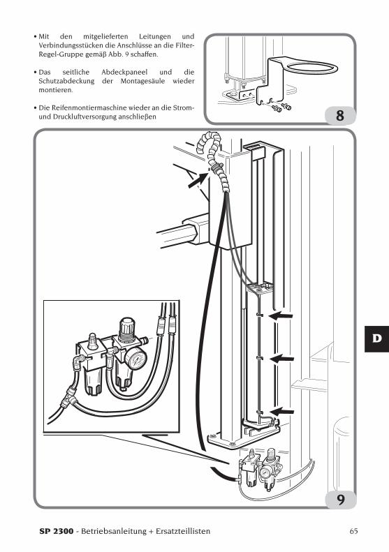
•Mit den mitgelieferten Leitungen undVerbindungsstücken die Anschlüsse an die Filter-Regel-Gruppe gemäß Abb. 9 schaffen.
•Das seitliche Abdeckpaneel und dieSchutzabdeckung der Montagesäule wieder montieren.
•DieReifenmontiermaschinewiederandieStrom-und Druckluftversorgung anschließen
9
8
66 SP 2300 - Betriebsanleitung + Ersatzteillisten
FUNKTIONSTEILE
10
1
2
4
3
5
6
7
10
98
11
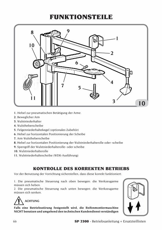
1. Hebel zur pneumatischen Betätigung der Arme.
2. Beweglicher Arm
3. Wulstniederhalter
4. Wulstheberscheibe
5. Felgenniederhaltekegel (optionales Zubehör)
6. Hebel zur horizontalen Positionierung der Scheibe
7. Arm Wulstheberscheibe
8. Hebel zur horizontalen Positionierung der Wulstniederhalterolle oder -scheibe
9. Sperrgriff der Wulstniederhalterolle- oder scheibe
10. Wulstniederhalterolle
11. Wulstniederhaltescheibe (WDK-Ausführung)
KONTROLLE DES KORREKTEN BETRIEBSVor der Benutzung der Vorrichtung sicherstellen, dass diese korrekt funktioniert:
1. Die pneumatische Steuerung nach oben bewegen: die Werkzeugarme müssen sich heben. 2. Die pneumatische Steuerung nach unten bewegen: die Werkzeugarme müssen sich senken.
ACHTUNG
Falls eine Betriebsstörung festgestellt wird, die Reifenmontiermaschine NICHT benutzen und umgehend den technischen Kundendienst verständigen
SP 2300 - Betriebsanleitung + Ersatzteillisten 67
D
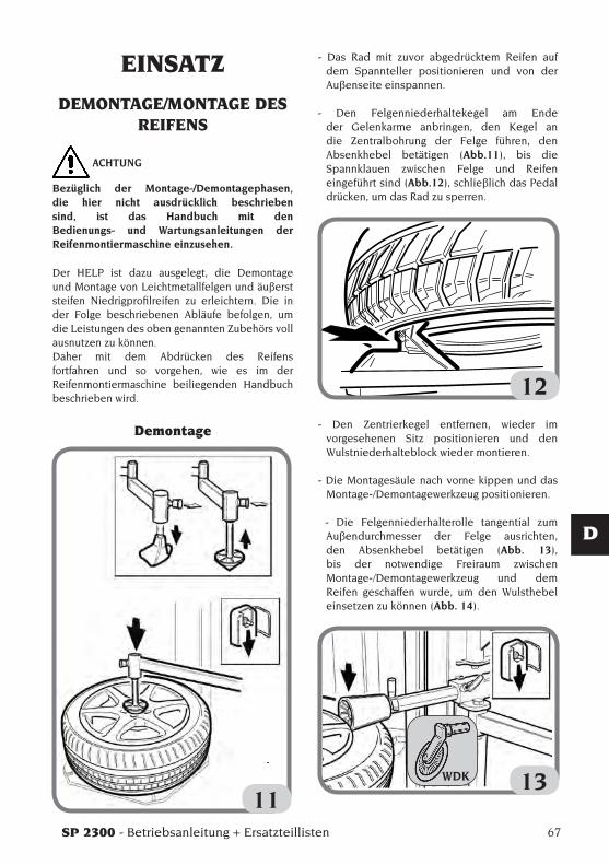
- Das Rad mit zuvor abgedrücktem Reifen auf dem Spannteller positionieren und von der Außenseite einspannen.
- Den Felgenniederhaltekegel am Ende der Gelenkarme anbringen, den Kegel an die Zentralbohrung der Felge führen, den Absenkhebel betätigen (Abb.11), bis die Spannklauen zwischen Felge und Reifen eingeführt sind (Abb.12), schließlich das Pedal drücken, um das Rad zu sperren.
12- Den Zentrierkegel entfernen, wieder im
vorgesehenen Sitz positionieren und den Wulstniederhalteblock wieder montieren.
- Die Montagesäule nach vorne kippen und das Montage-/Demontagewerkzeug positionieren.
- Die Felgenniederhalterolle tangential zum Außendurchmesser der Felge ausrichten, den Absenkhebel betätigen (Abb. 13), bis der notwendige Freiraum zwischen Montage-/Demontagewerkzeug und dem Reifen geschaffen wurde, um den Wulsthebel einsetzen zu können (Abb. 14).
13
EINSATZ
DEMONTAGE/MONTAGE DES REIFENS
ACHTUNG
Bezüglich der Montage-/Demontagephasen, die hier nicht ausdrücklich beschrieben sind, ist das Handbuch mit den Bedienungs- und Wartungsanleitungen der Reifenmontiermaschine einzusehen.
Der HELP ist dazu ausgelegt, die Demontage und Montage von Leichtmetallfelgen und äußerst steifen Niedrigprofilreifen zu erleichtern. Die in der Folge beschriebenen Abläufe befolgen, um die Leistungen des oben genannten Zubehörs voll ausnutzen zu können. Daher mit dem Abdrücken des Reifens fortfahren und so vorgehen, wie es im der Reifenmontiermaschine beiliegenden Handbuch beschrieben wird.
Demontage
11WDK

68 SP 2300 - Betriebsanleitung + Ersatzteillisten
14- Die Wulstniederhalterolle entfernen, den
Wulstniederhalteblock gegenüber dem Montage-/Demontagewerkzeug positionieren, den Absenkhebel betätigen, sodass der Wulst in das Felgenbett tritt (Abb.15).
15- Den Wulst über das Montage-/Demontagewerkzeug
stülpen, den Wulstniederhalteblock entfernen, das Pedal für die Drehbewegung drücken und den ersten Wulst herausziehen (Abb.16).
- Den unteren Wulst bis zum oberen Felgenrand führen; in einigen Fällen kann der Wulst trotzzuvor abgedrücktem Reifen nicht aus seinem Sitz entfernt werden, da er an der Felge haften bleibt. In diesen Fällen die Scheibe zwischen dem unteren Wulst und der Felge einführen (Abb.17),
das Pedal für die Drehbewegung drücken und den Wulst anheben.
16
17Der zweite Wulst kann auf konventionelle Weise mit dem Hebel oder mit der Wulstniederhalterolle demontiert werden.
- Die Rolle tangential zum äußeren Felgenrand positionieren (Abb. 18).
18
WDK
WDK
WDK
WDK
SP 2300 - Betriebsanleitung + Ersatzteillisten 69
D
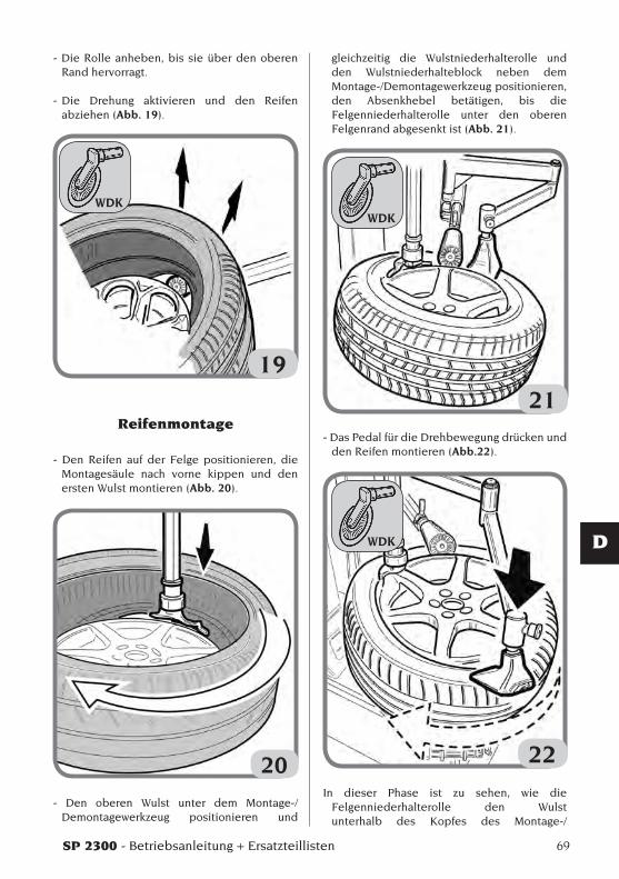
- Die Rolle anheben, bis sie über den oberen Rand hervorragt.
- Die Drehung aktivieren und den Reifen abziehen (Abb. 19).
19
Reifenmontage
- Den Reifen auf der Felge positionieren, die Montagesäule nach vorne kippen und den ersten Wulst montieren (Abb. 20).
20
- Den oberen Wulst unter dem Montage-/Demontagewerkzeug positionieren und
gleichzeitig die Wulstniederhalterolle und den Wulstniederhalteblock neben dem Montage-/Demontagewerkzeug positionieren, den Absenkhebel betätigen, bis die Felgenniederhalterolle unter den oberen Felgenrand abgesenkt ist (Abb. 21).
21- Das Pedal für die Drehbewegung drücken und
den Reifen montieren (Abb.22).
22In dieser Phase ist zu sehen, wie die
Felgenniederhalterolle den Wulst unterhalb des Kopfes des Montage-/
WDKWDK
WDK
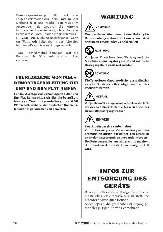
70 SP 2300 - Betriebsanleitung + Ersatzteillisten
Demontagewerkzeugs hält und der Felgenniederhalteblock dem Rad in der Drehung folgt und hierbei den Wulst im Felgenbett hält, wodurch die korrekte Montage gewährleistet wird, ohne dass der Bedieners mit den Händen eingreifen muss.
HINWEIS: Die Drehung unterbrechen, wenn der Wulstniederhalter sich in der Nähe des Montage-/Demontagewerkzeugs befindet.
- Den Hochfahrhebel betätigen und die Rolle und den Wulstniederhalter vom Rad entfernen.
FREIGEGEBENE MONTAGE-/DEMONTAGEANLEITUNG FÜR UHP UND RUN FLAT REIFEN
Für die Montage und Demontage von UHP und Run Flat Reifen bitten wir Sie, die beigefügte Montage-/Demontageanleitung des WDK (Wirtschaftsverband der deutschen Kautschu-kindustrie) genauestens zu beachten.
WARTUNG
ACHTUNG
Der Hersteller. übernimmt keine Haftung für Beanstandungen durch Gebrauch von nicht originalen Ersatz- oder Zubehörteilen.
ACHTUNG
Vor jeder Einstellung bzw. Wartung muß die Maschine spannungslos gesetzt und sämtliche Bewegungsteile gesichert werden.
ACHTUNG
Die Teile dieser Maschine dürfen ausschließlich zwecks Servicearbeiten abgenommen oder geändert werden.
GEFAHR
Vor jeglicher Wartungsarbeit oder dem Nachfül-len des Schmiermittels die Maschine von der Druckluftversorgung trennen.
HINWEIS
Den Arbeitsbereich sauberhalten.Zur Entfernung von Verschmutzungen oder Fremdteilen dürfen auf keinen Fall Druckluft und/oder Wasserstrahlen verwendet werden.Bei Reinigungsarbeiten ist derart vorzugehen, daß Staub weder entsteht noch aufgewirbelt wird.
INFOS ZUR ENTSORGUNG DES
GERÄTSBei eventueller Verschrottung des Geräts die elektrischen, elektronischen, Kunststoff- und Eisenteile vorsorglich trennen.Anschließend die getrennte Entsorgung ge-mäß der gültigen Normen vornehmen.
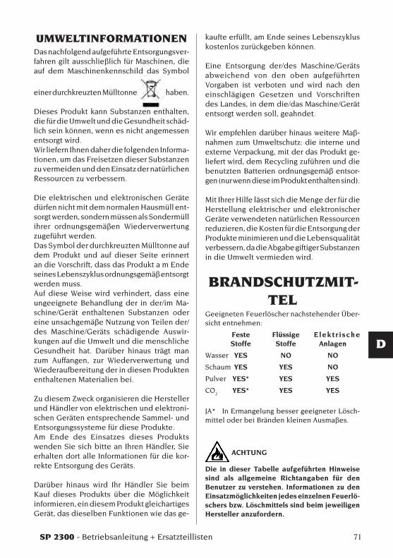
SP 2300 - Betriebsanleitung + Ersatzteillisten 71
D
UMWELTINFORMATIONENDas nachfolgend aufgeführte Entsorgungsver-fahren gilt ausschließlich für Maschinen, die auf dem Maschinenkennschild das Symbol
einer durchkreuzten Mülltonne haben.
Dieses Produkt kann Substanzen enthalten, die für die Umwelt und die Gesundheit schäd-lich sein können, wenn es nicht angemessen entsorgt wird.Wir liefern Ihnen daher die folgenden Informa-tionen, um das Freisetzen dieser Substanzen zu vermeiden und den Einsatz der natürlichen Ressourcen zu verbessern.
Die elektrischen und elektronischen Geräte dürfen nicht mit dem normalen Hausmüll ent-sorgt werden, sondern müssen als Sondermüll ihrer ordnungsgemäßen Wiederverwertung zugeführt werden.Das Symbol der durchkreuzten Mülltonne auf dem Produkt und auf dieser Seite erinnert an die Vorschrift, dass das Produkt a m Ende seines Lebenszyklus ordnungsgemäß entsorgt werden muss.Auf diese Weise wird verhindert, dass eine ungeeignete Behandlung der in der/im Ma-schine/Gerät enthaltenen Substanzen oder eine unsachgemäße Nutzung von Teilen der/des Maschine/Geräts schädigende Auswir-kungen auf die Umwelt und die menschliche Gesundheit hat. Darüber hinaus trägt man zum Auffangen, zur Wiederverwertung und Wiederaufbereitung der in diesen Produkten enthaltenen Materialien bei.
Zu diesem Zweck organisieren die Hersteller und Händler von elektrischen und elektroni-schen Geräten entsprechende Sammel- und Entsorgungssysteme für diese Produkte.Am Ende des Einsatzes dieses Produkts wenden Sie sich bitte an Ihren Händler, Sie erhalten dort alle Informationen für die kor-rekte Entsorgung des Geräts.
Darüber hinaus wird Ihr Händler Sie beim Kauf dieses Produkts über die Möglichkeit informieren, ein diesem Produkt gleichartiges Gerät, das dieselben Funktionen wie das ge-
kaufte erfüllt, am Ende seines Lebenszyklus kostenlos zurückgeben können.
Eine Entsorgung der/des Maschine/Geräts abweichend von den oben aufgeführten Vorgaben ist verboten und wird nach den einschlägigen Gesetzen und Vorschriften des Landes, in dem die/das Maschine/Gerät entsorgt werden soll, geahndet.
Wir empfehlen darüber hinaus weitere Maß-nahmen zum Umweltschutz: die interne und externe Verpackung, mit der das Produkt ge-liefert wird, dem Recycling zuführen und die benutzten Batterien ordnungsgemäß entsor-gen (nur wenn diese im Produkt enthalten sind).
Mit Ihrer Hilfe lässt sich die Menge der für die Herstellung elektrischer und elektronischer Geräte verwendeten natürlichen Ressourcen reduzieren, die Kosten für die Entsorgung der Produkte minimieren und die Lebensqualität verbessern, da die Abgabe giftiger Substanzen in die Umwelt vermieden wird.
BRANDSCHUTZMIT-TEL
Geeigneten Feuerlöscher nachstehender Über-sicht entnehmen:
Feste Flüssige Elektr ische Stoffe Stoffe Anlagen
Wasser YES NO NO
Schaum YES YES NO
Pulver YES* YES YES
CO2 YES* YES YES
JA* In Ermangelung besser geeigneter Lösch-mittel oder bei Bränden kleinen Ausmaßes.
ACHTUNG
Die in dieser Tabelle aufgeführten Hinweise sind als allgemeine Richtangaben für den Benutzer zu verstehen. Informationen zu den Einsatzmöglichkeiten jedes einzelnen Feuerlö-schers bzw. Löschmittels sind beim jeweiligen Hersteller anzufordern.
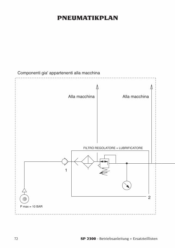
72 SP 2300 - Betriebsanleitung + Ersatzteillisten
PNEUMATIKPLAN

SP 2300 - Betriebsanleitung + Ersatzteillisten 73
D
460442_1

Note
74 SP 2300 - Betriebsanleitung + Ersatzteillisten
SP 2300 - Manual de uso + repuestos 75
E
ÍNDICEINTRODUCCIÓN ........................................................................................... 76DESCRIPCIÓN GRUPOS DISPONIBLES .................................................... 77DESCRIPCIÓN COMBINACIONES .............................................................. 77TRANSPORTE, ALMACENAMIENTO Y DESPLAZAMIENTO ................... 79
Condiciones para el transporte de la máquina y datos técnicos ..... 79Condiciones del ambiente de transporte y almacenamiento de la máquina ......................................................................................... 79
NORMAS DE SEGURIDAD .......................................................................... 79INSTALACIÓN EN LA DESMONTADORA DE NEUMÁTICOS .................. 80PIEZAS FUNCIONALES ............................................................................... 84CONTROL DEL FUNCIONAMIENTO CORRECTO .................................... 84USO ................................................................................................................ 85
Desmontaje/Montaje del neumático ................................................... 85Procedimiento homologado de desmontaje y montaje de neumáticos UHP y Run Flat ............................................................. 88
MANTENIMIENTO ....................................................................................... 88INFORMACIÓN SOBRE EL DESGUACE .................................................... 89MEDIOS CONTRA-INCENDIO QUE SE DEBEN UTILIZAR ...................... 89ESQUEMA NEUMÁTICO .............................................................................. 90
76 SP 2300 - Manual de uso + repuestos
INTRODUCCIONEl objeto de esta publicación es suministrar al propietario y al operador unas instrucciones eficaces y seguras para el uso y el mantenimiento de la unidad de potencia SP 3000.En el respeto de estas instrucciones podrán obtenerse de la máquina la eficacia y duración características de los productos, que son los mejores aliados para facilitar el trabajo.A continuación se indican las definiciones de los diversos niveles de peligro, con las respectivas expresiones de señalización que se utilizan en este manual.
PELIGROPeligros inmediatos que provocan graves le-siones o muerte.
ATENCIONPeligros o procedimientos poco seguros que pueden provocar graves lesiones o muerte.
ADVERTENCIAPeligros o procedimientos poco seguros que pueden provocar lesiones no graves o daños materiales.
Leer atentamente estas instrucciones antes de poner la máquina en funcionamiento. Conservar este manual en una carpeta, junto con el resto del material ilustrativo que se entrega con la máquina, y dejarla en el puesto de trabajo al alcance del operador.La documentación técnica que se suministra al cliente es parte integrante de la máquina, por lo cual deberá entregarse con ésta en caso de venta.El manual debe considerarse válido exclusiva-mente para el modelo y la matrícula máquina que aparecen indicados en la placa.
ATENCION
Operar la máquina solamente como se indica en este manual: el destino de la misma a usos no expresamente descritos quedará bajo la entera responsabilidad del operador.
NOTAAlgunas de las ilustraciones de este manual han sido realizadas con fotos de prototipos. Las máquinas de producción estándar pueden diferir en algunos detalles.Estas instrucciones están destinadas a personas con ciertos conocimientos sobre mecánica. Por ello, se ha omitido la descripción de cada ope-ración individual, como el método para ajustar o aflojar los dispositivos de fijación. No realizar ninguna operación que supere el propio nivel de capacidad operativa, o en la cual no se ten-ga la debida experiencia. En caso de necesitar asistencia, acudir a un centro técnico autorizado.
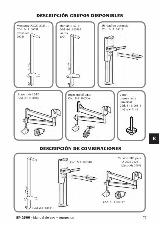
SP 2300 - Manual de uso + repuestos 77
E
DESCRIPCIÓN GRUPOS DISPONIBLES
Montante A2020-2025 ....Cód. 8-11100351(después2004)
Montante A210Cód. 8-11100307(antes 2004)
Unidad de potencia Cód. 8-11100310
Brazo móvil STDCód. 8-11100309
Brazo móvil WDKCód. 8-11100306
Cono prensallanta universal Cód. 8-11100311 (bajo pedido)
DESCRIPCIÓN DE COMBINACIONES
Versión STD para A 2020-2025 ...
(después 2004)
Cód. 8-11100351
Cód. 8-11100310
Cód. 8-11100309
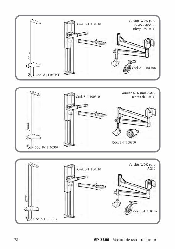
78 SP 2300 - Manual de uso + repuestos
Versión WDK para A 2020-2025 ...
(después 2004)
Versión STD para A 210 (antes del 2004)
Versión WDK para A 210
Cód. 8-11100351
Cód. 8-11100310
Cód. 8-11100306
Cód. 8-11100307
Cód. 8-11100310
Cód. 8-11100309
Cód. 8-11100307
Cód. 8-11100310
Cód. 8-11100306
SP 2300 - Manual de uso + repuestos 79
E
NORMAS DE SEGURIDADEl equipo está destinado a un uso exclusivamente profesional.
ATENCION
En el equipo puede operar un solo operador a la vez.
ATENCION
La inobservancia de las instrucciones y adver-tencias de peligro puede ser motivo de graves lesiones a los operadores y a otras personas presentes. No poner la máquina en marcha sin antes haber leído y comprendido todas las señalizaciones de peligro, atención y adverten-cia de este manual.
Para utilizar correctamente esta máquina es ne-cesario ser un operador cualificado y autorizado, capaz de comprender las instrucciones escritas que suministra el fabricante, tener un adecuado entrenamiento y conocer las reglas de seguridad. El operador no debe consumir drogas ni alcohol, los cuales podrían alterar su capacidad. En todos los casos, es indispensable:- Saber leer y poder comprender las indicaciones.- Estudiar las prestaciones y características de
la máquina.- Evitar que las personas no autorizadas se
aproximen a la zona de trabajo.- Cerciorarse de que la instalación de la máquina
se haya realizado de conformidad con todas las normas y reglamentaciones vigentes en la materia.
- Asegurarse de que todos los operadores estén convenientemente entrenados, que sepan utilizar el aparato de manera correcta y segura, y que haya una adecuada supervisión.
- No dejar nunca sobre la máquina tuercas, tornillos, herramientas u otros objetos que durante el trabajo puedan introducirse entre las partes móviles de la misma.
- No tocar ninguna línea, ni las partes internas de motores o dispositivos eléctricos, sin antes cerciorarse de que se haya cortado la corriente.
- Leer con atención este manual y aprender a utilizar la máquina correctamente y en condi-ciones seguras.
- Tener este manual siempre a mano en un lugar fácilmente accesible y no dejar de consultarlo.
TRANSPORTE, ALMACENAMIENTO Y
TRASLADO
Condiciones de transporte de la máquina y datos técnicos
El kit montante y la SP 2300 se deben transportar en su respectivo embalaje original y se deben mantener en la posición indicada en el propio embalaje.
SP 2300
- diámetro máximo cubierta ......................1080 mm- diámetro llanta ....................... mín. 10” - máx. 26”- ancho llanta ............................... mín. 4” - máx. 14” - fuerza cilindro destalonador .......9300 N a 10 bar- presión de trabajo .......................................10 bar
•Peso: - Montante ......................................................... 18 kg - Unidad de potencia .................................... 48 kg- Brazo móvil ................................................... 19 kg- Cono prensallanta universal ...................... 1 kg
Condiciones ambientales para el transporte y almacenamiento
de la máquinaTemperatura: -25°C ÷ +55°C.
ATENCION
Para evitar que la máquina se dañe, no colocar ningún otro bulto sobre el embalaje.
ADVERTENCIA
Conservar los embalajes originales para even-tuales transportes en el futuro.
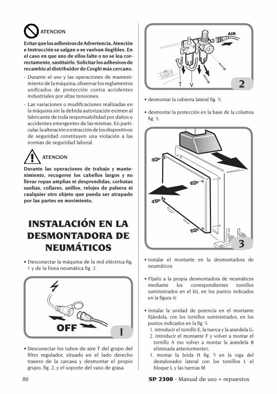
80 SP 2300 - Manual de uso + repuestos
ATENCION
Evitar que los adhesivos de Advertencia, Atención e Instrucción se salgan o se vuelvan ilegibles. En el caso en que uno de ellos falte o no se lea cor-rectamente, sustituirlo. Solicitar los adhesivos de recambio al distribuidor de Corghi más cercano.
- Durante el uso y las operaciones de manteni-miento de la máquina, observar los reglamentos unificados de protección contra accidentes industriales por altas tensiones.
- Las variaciones o modificaciones realizadas en la máquina sin la debida autorización eximen al fabricante de toda responsabilidad por daños o accidentes emergentes de las mismas. En parti-cular, la alteración o extracción de los dispositivos de seguridad constituyen una violación a las normas de seguridad laboral.
ATENCION
Durante las operaciones de trabajo y mante-nimiento, recogerse los cabellos largos y no llevar ropas amplias ni desprendidas, corbatas sueltas, collares, anillos, relojes de pulsera ni cualquier otro objeto que pueda ser atrapado por las partes en movimiento.
INSTALACIÓN EN LA DESMONTADORA DE
NEUMÁTICOS•Desconectarlamáquinadelaredeléctricafig.
1 y de la línea neumática fig. 2.
1•DesconectarlostubosdeaireTdelgrupodel
filtro regulador, situado en el lado derecho trasero de la carcasa y desmontar el propio grupo, fig. 2, y el soporte del vaso de grasa
T V 2•desmontarlacubiertalateralfig.3;
•desmontarlaprotecciónenlabasedelacolumnafig.3;
3•instalar el montante en la desmontadora de
neumáticos
•Fijarlo a la propia desmontadora de neumáticosmediante los correspondientes tornillos suministrados en el kit, en los puntos indicados en la figura 4)
•instalar la unidad de potencia en el montantefijándola, con los tornillos suministrados, en los puntos indicados en la fig. 5:1.introducireltornilloE,latuercaylaarandelaG;2. introducir el montante F y volver a montar el
tornillo A (no volver a montar la arandela B eliminadaanteriormente);
3. montar la brida H fig. 5 en la viga del destalonador lateral con los tornillos I, el bloque L y las tuercas M
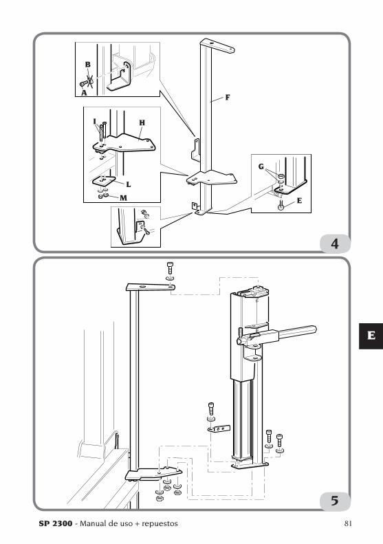
SP 2300 - Manual de uso + repuestos 81
E
4
A
B
E
F
G
HI
L
M
5
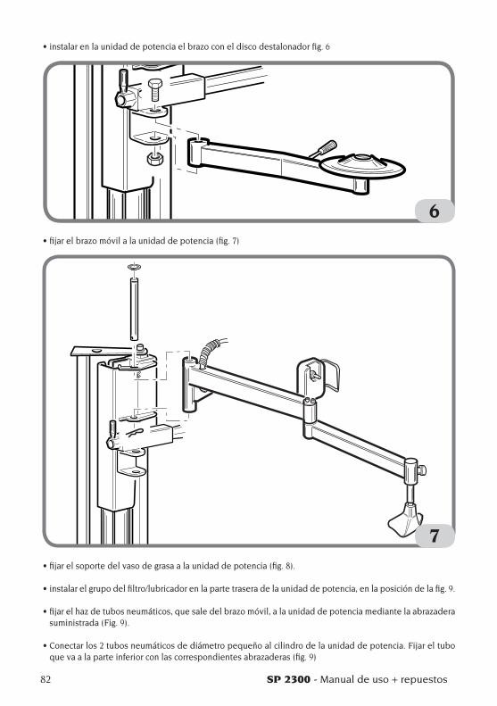
82 SP 2300 - Manual de uso + repuestos
•instalarenlaunidaddepotenciaelbrazoconeldiscodestalonadorfig.6
6•fijarelbrazomóvilalaunidaddepotencia(fig.7)
7•fijarelsoportedelvasodegrasaalaunidaddepotencia(fig.8).
•instalarelgrupodelfiltro/lubricadorenlapartetraseradelaunidaddepotencia,enlaposicióndelafig.9.
•fijarelhazdetubosneumáticos,quesaledelbrazomóvil,alaunidaddepotenciamediantelaabrazaderasuministrada (Fig. 9).
•Conectarlos2tubosneumáticosdediámetropequeñoalcilindrodelaunidaddepotencia.Fijareltuboque va a la parte inferior con las correspondientes abrazaderas (fig. 9)
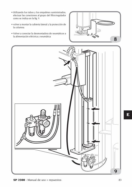
SP 2300 - Manual de uso + repuestos 83
E
•Utilizandolostubosylosempalmessuministrados,efectuar las conexiones al grupo del filtro/regulador como se indica en la fig. 9.
•volveramontarlacubiertalateralylaproteccióndela columna.
•Volveraconectarladesmontadoradeneumáticosala alimentación eléctrica y neumática
9
8
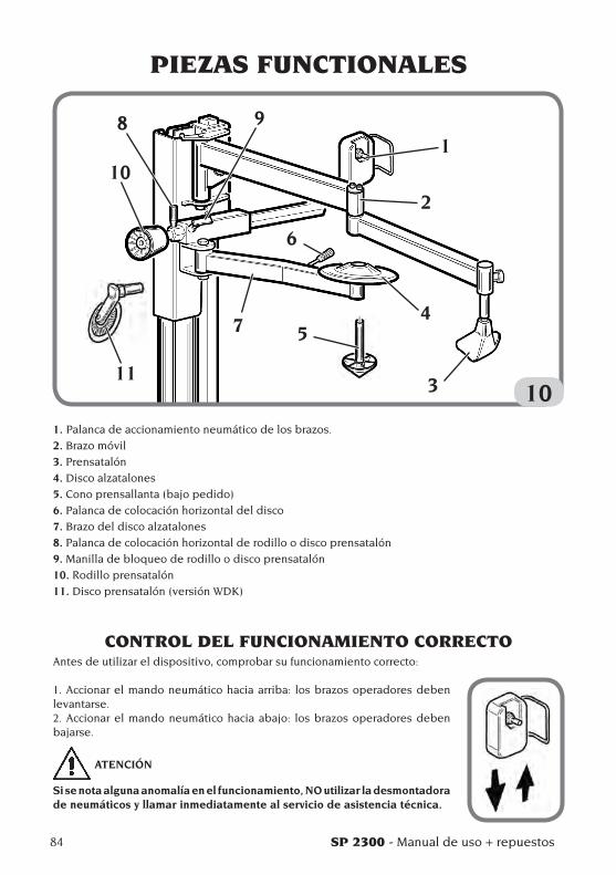
84 SP 2300 - Manual de uso + repuestos
PIEZAS FUNCTIONALES
10
1
2
4
3
5
6
7
10
98
11
1. Palanca de accionamiento neumático de los brazos.
2. Brazo móvil
3. Prensatalón
4. Disco alzatalones
5. Cono prensallanta (bajo pedido)
6. Palanca de colocación horizontal del disco
7. Brazo del disco alzatalones
8. Palanca de colocación horizontal de rodillo o disco prensatalón
9. Manilla de bloqueo de rodillo o disco prensatalón
10. Rodillo prensatalón
11. Disco prensatalón (versión WDK)
CONTROL DEL FUNCIONAMIENTO CORRECTOAntes de utilizar el dispositivo, comprobar su funcionamiento correcto:
1. Accionar el mando neumático hacia arriba: los brazos operadores deben levantarse.2. Accionar el mando neumático hacia abajo: los brazos operadores deben bajarse.
ATENCIÓN
Si se nota alguna anomalía en el funcionamiento, NO utilizar la desmontadora de neumáticos y llamar inmediatamente al servicio de asistencia técnica.
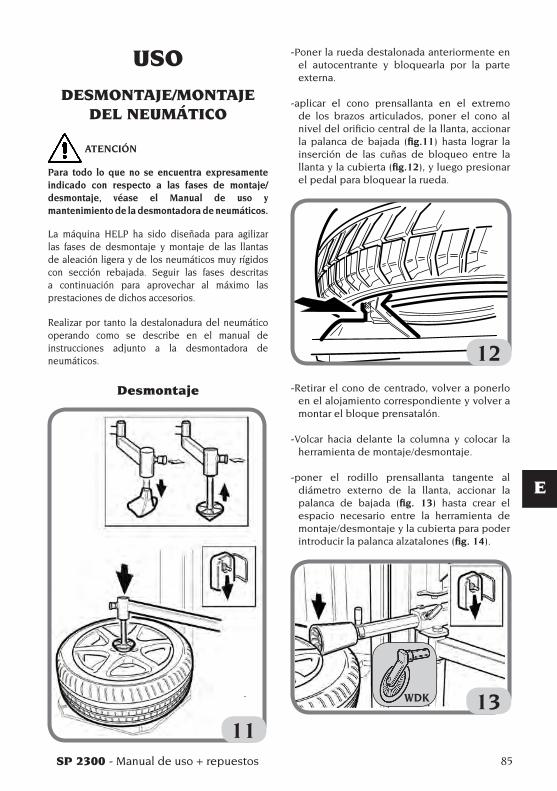
SP 2300 - Manual de uso + repuestos 85
E
-Poner la rueda destalonada anteriormente en el autocentrante y bloquearla por la parte externa.
-aplicar el cono prensallanta en el extremo de los brazos articulados, poner el cono al nivel del orificio central de la llanta, accionar la palanca de bajada (fig.11) hasta lograr la inserción de las cuñas de bloqueo entre la llanta y la cubierta (fig.12), y luego presionar el pedal para bloquear la rueda.
12-Retirar el cono de centrado, volver a ponerlo
en el alojamiento correspondiente y volver a montar el bloque prensatalón.
-Volcar hacia delante la columna y colocar la herramienta de montaje/desmontaje.
-poner el rodillo prensallanta tangente al diámetro externo de la llanta, accionar la palanca de bajada (fig. 13) hasta crear el espacio necesario entre la herramienta de montaje/desmontaje y la cubierta para poder introducir la palanca alzatalones (fig. 14).
13
USO
DESMONTAJE/MONTAJE DEL NEUMÁTICO
ATENCIÓN
Para todo lo que no se encuentra expresamente indicado con respecto a las fases de montaje/desmontaje, véase el Manual de uso y mantenimiento de la desmontadora de neumáticos.
La máquina HELP ha sido diseñada para agilizar las fases de desmontaje y montaje de las llantas de aleación ligera y de los neumáticos muy rígidos con sección rebajada. Seguir las fases descritas a continuación para aprovechar al máximo las prestaciones de dichos accesorios.
Realizar por tanto la destalonadura del neumático operando como se describe en el manual de instrucciones adjunto a la desmontadora de neumáticos.
Desmontaje
11
WDK

86 SP 2300 - Manual de uso + repuestos
14- retirar el rodillo prensatalón, colocar el
bloque prensatalón en posición opuesta a la herramienta de montaje/desmontaje, accionar la palanca de bajada para obtener la inserción del talón dentro del canal de la llanta (fig.15).
15-cargar el talón sobre la herramienta de
montaje/desmontaje, aflojar el bloque prensatalón, presionar el pedal de rotación y extraer el primer talón (fig.16).
-Poner el talón inferior hasta el borde superior de la llanta; en algunos casos, aunque larueda se haya destalonado, el talón inferior no se desplaza de su alojamiento porque permanece agarrado en la llanta. En tales
casos, utilizar el disco introduciéndolo entre el talón inferior y la llanta (fig.17), presionar el pedal de rotación y levantar.
16
17El desmontaje del segundo talón se puede efectuar de la manera tradicional con la palanca o utilizando el rodillo prensatalón.- Colocar el rodillo tangente al borde externo
de la llanta (fig. 18).
18
WDK
WDK
WDK
WDK

SP 2300 - Manual de uso + repuestos 87
E
-Levantar el rodillo hasta hacer que sobresalga por el borde superior.
- Accionar la rotación y extraer la cubierta. (fig. 19)
19
Montaje de neumáticos
- Apoyar la cubierta en la llanta y enderezar hacia delante la columna, montar el primer talón (fig. 20).
20
-Colocar el talón superior debajo de la herramienta de montaje/desmontaje, colocar
simultáneamente el rodillo prensatalón y el bloque prensatalón cerca de la herramienta de montaje/desmontaje, accionar la palanca de bajada hasta obtener la bajada del rodillo prensallanta bajo el borde superior de la llanta (fig. 21).
21-Presionar el pedal de rotación y montar la
cubierta (fig.22).
22 En esta fase, se verá el rodillo prensallanta
que mantiene el talón bajo el cabezal de la herramienta de montaje/desmontaje y el
WDKWDK
WDK

88 SP 2300 - Manual de uso + repuestos
bloque prensatalón seguirá la rueda en la ro-tación manteniendo el talón dentro del canal, garantizando así el montaje correcto sin ayuda de las manos por parte del operador.
NOTA: interrumpir la rotación cuando el prensatalón esté cerca de la herramienta de montaje/desmontaje.
-Accionar la palanca de subida, liberar la rueda del rodillo y del prensatalón.
PROCEDIMIENTO HOMOLOGADO DE
DESMONTAJE Y MONTAJE NEUMATICOS UHP Y RUN
FLATPara el procedimiento detallado de desmon-taje/montaje de neumáticos UHP y RUNFLAT referirse a las instrucciones del manual re-dactado por WDK (Asociación Alemana de la Industria del Neumático)
MANTENIMIENTO
ATENCIÓN
Corghi S.p.A. declina toda responsabilidad en caso de inconvenientes causados por el uso de piezas de recambio o accesorios no originales.
ATENCIÓN
Antes de realizar cualquier operación de reglaje o mantenimiento, desconectar la máquina de la alimentación eléctrica y neumática, y ase-gurarse de que todas las partes móviles estén bloqueadas.
ATENCIÓN
No extraer ni modificar ningún componente de esta máquina (salvo para la asistencia).
PELIGRO
Antes de efectuar cualquier operación de mantenimiento o relleno de lubricante, la máquina debe ser desconectada de la línea de alimentación neumática.
ADVERTENCIA
Mantener siempre limpia la zona de trabajo.No utilizar nunca aire comprimido ni chorros de agua o solvente para limpiar la máquina.En las operaciones de limpieza, evitar en la me-dida de lo posible que se forme o levante polvo.
INFORMACIONES SOBRE EL DESGUACE
Para desechar la máquina, separar previamen-te los componentes eléctricos, electrónicos, plásticos y ferrosos.Luego proceder a la eliminación selectiva, conforme a lo dispuesto por las leyes vigentes.
SP 2300 - Manual de uso + repuestos 89
E
INFORMACIONES AMBIENTALES
El siguiente procedimiento de eliminación tiene que ser aplicado exclusivamente a las máquinas con placa datos máquina que trae
el símbolo del bidón barrado .
Este producto puede contener sustancias que pueden ser dañinas para el entorno y para la salud humana si no es eliminado adecuadamente.Les entregamos por tanto la siguiente informa-ción para evitar el vertido de estas sustancias y para mejorar el uso de los recursos naturales.
Los equipamientos eléctricos y electrónicos no deben ser eliminados a través de los normales desechos urbanos, tienen que ser enviados a una recogida selectiva para su correcto tratamiento.El símbolo del bidón tachado, colocado so-bre el producto y en esta página, recuerda la necesidad de eliminar adecuadamente el producto al final de su vida.De esta manera es posible evitar que un tratamiento no específico de las sustancias contenidas en estos productos o un uso im-propio de partes de los productos mismos pueda tener consecuencias dañinas para el ambiente y para la salud humana. Además, se contribuye a la recuperación, reciclaje y reutilización de muchos materiales contenidos en estos productos.
Con tal objetivo los fabricantes y distribuidores de los equipamientos eléctricos y electrónicos organizan adecuados sistemas de recogida y eliminación de estos productos.Al final de la vida del producto contacte con su distribuidor para obtener información acerca de las modalidades de recogida.
En el momento de la adquisición de un nuevo producto su distribuidor le informará también de la posibilidad de devolver gratuitamente otro instrumento con vida finalizada a con-dición que sea de tipo equivalente y haya desarrollado las mismas funciones del pro-ducto adquirido.
Una eliminación del producto diferente de aquella arriba indicada podrá conllevar las sanciones previstas por la normativa vigente en el país de eliminación del producto.
Les recomendamos también de adoptar otras medidas favorables al entorno: reciclar el embalaje interior y exterior con el cual el producto es suministrado y eliminar de manera adecuada las baterías usadas (sólo si están contenidas en el producto).Con su ayuda se puede reducir la cantidad de recursos naturales empleados en la fabri-cación de equipos eléctricos y electrónicos, minimizar el empleo de los vertederos para la eliminación de los productos y mejorar la calidad de la vida, evitando que sustancias potencialmente peligrosas sean vertidas al medio ambiente.
MEDIOS ANTI-INCENDIO
Para escoger el extintor más adecuado, consultar la siguiente tabla:
Materiales Líquidos E q u i p o s secos inflamables eléctricos
Hídrico SI NO NO
Espuma SI SI NO
Pólvora SI* SI SI
CO2 SI* SI SI
SI* Se puede utilizar si faltan medios más ade-cuados o para incendios no muy grandes
ATENCION
Las indicaciones de esta tabla son de carácter general y están destinadas a servir como guía meramente indicativa para los usuarios. Para las posibilidades de uso de cada tipo de extintor, consultar al respectivo fabricante.
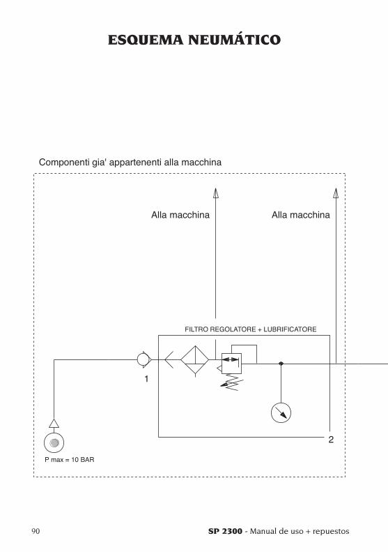
90 SP 2300 - Manual de uso + repuestos
ESQUEMA NEUMÁTICO

SP 2300 - Manual de uso + repuestos 91
E
460442_1

Note
92 SP 2300 - Manual de uso + repuestos

SP 2300 93
Pezzi di ricambio
Spare parts list
Pieces de rechange
Ersatzteilliste
Repuestos
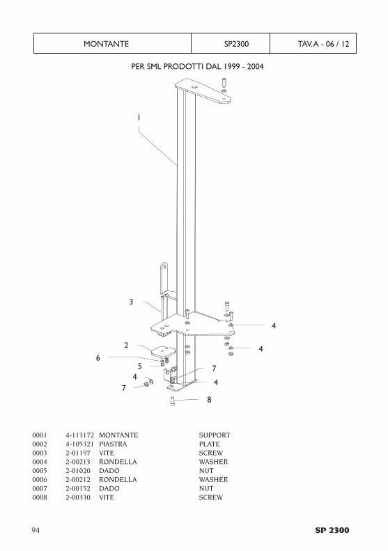
94 SP 2300
MONTANTE SP2300 TAV. A - 06 / 12
1
0001 4-113172 MONTANTE SUPPORT0002 4-105321 PIASTRA PLATE0003 2-01197 VITE SCREW0004 2-00213 RONDELLA WASHER0005 2-01020 DADO NUT0006 2-00212 RONDELLA WASHER0007 2-00152 DADO NUT0008 2-00330 VITE SCREW
PER SML PRODOTTI DAL 1999 - 2004
2
3
4
4
56
7
44
78

SP 2300 95
MONTANTE SP2300 TAV. A1 - 06 / 12
11
PER SML PRODOTTI DAL 2004
2
3
4
4
5
6
7
44
7
8
7
8
4
8
0011 4-115177 MONTANTE SUPPORT0002 4-105321 PIASTRA PLATE0003 2-01197 VITE SCREW0004 2-00213 RONDELLA WASHER0005 2-01020 DADO NUT0006 2-00212 RONDELLA WASHER0007 2-00152 DADO NUT0008 2-00330 VITE SCREW
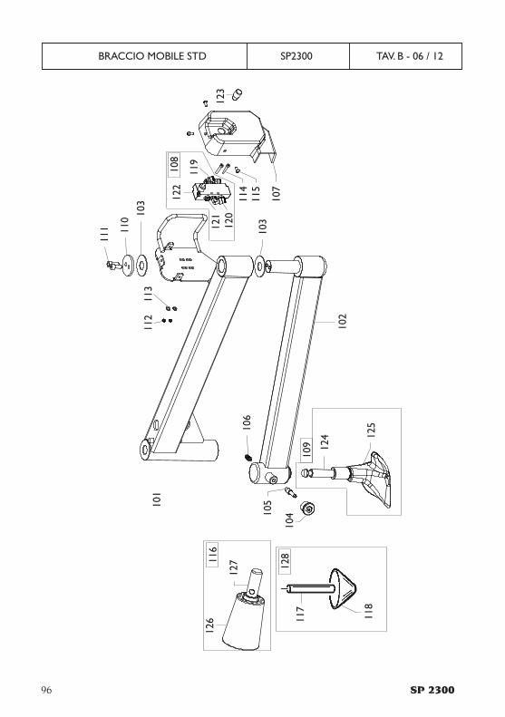
96 SP 2300
BRACCIO MOBILE STD SP2300 TAV. B - 06 / 12
101
102
103
105
106
107
103
122
121
120
123
114
119
110
111
113
112
126
127
117
118
124 12
5
104
109
12811
6
108
115
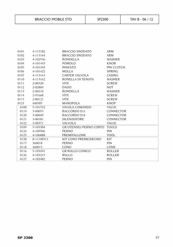
SP 2300 97
BRACCIO MOBILE STD SP2300 TAV. B - 06 / 12
0101 4-113182 BRACCIO SNODATO ARM0102 4-113164 BRACCIO SNODATO ARM0103 4-102536 RONDELLA WASHER0104 4-101443 POMOLO KNOB0105 4-101444 INNESTO PIN CLUTCH0106 4-101422 MOLLA SPRING0107 4-113163 CARTER VALVOLA CASING0110 4-113162 RONELLA DI TENUTA WASHER0111 2-00320 VITE SCREW0112 2-02804 DADO NUT0113 2-00210 RONDELLA WASHER0114 2-91668 VITE SCREW0115 2-80121 VITE SCREW0123 440585 MANOPOLA KNOP
0108 5-101552 VAVOLA COMANDO VALVE0119 3-00053 RACCORDO D.6 CONNECTOR0120 3-00049 RACCORDO D.8 CONNECTOR0121 3-00181 SILENZIATORE CONNECTOR0122 3-00371 VALVOLA VALVE0109 5-103384 GR.UTENSILI PERNO CORTO TOOLS0124 4-109506 PERNO PIN0125 4-106888 PREMITALLONE TOOL0128 8-11100311 KIT CONO PREMICERCHIO KIT0117 360018 PERNO PIN0118 460013 CONO CONE0116 5-103491 GR.RULLO CONICO ROLLER0126 4-103215 RULLO ROLLER0127 4-102482 PERNO PIN
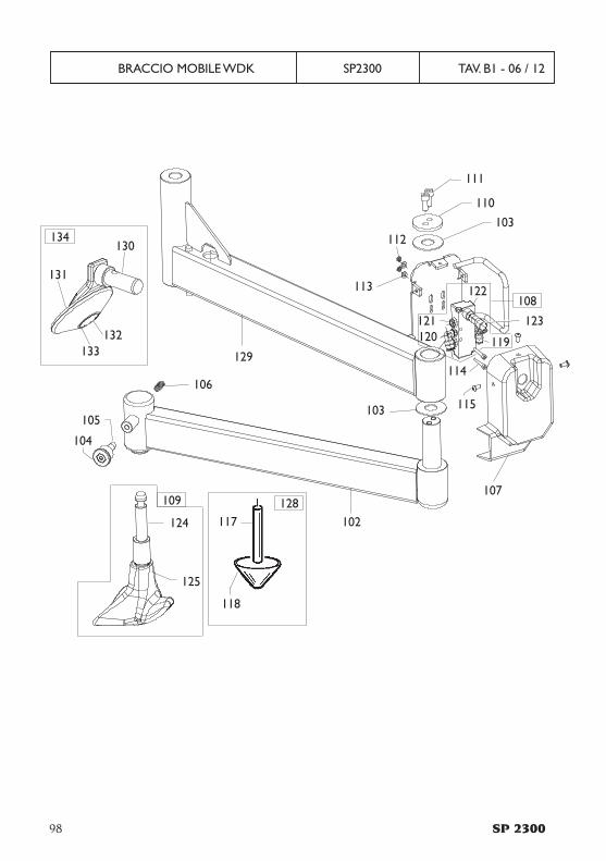
98 SP 2300
BRACCIO MOBILE WDK SP2300 TAV. B1 - 06 / 12
102
103
105
106
107
103
122
121120
114
119
110
111
113
112
117
118
124
125
104
109 128
108
115
129
123
130
131
132133
134

SP 2300 99
BRACCIO MOBILE WDK SP2300 TAV. B1 - 06 / 12
0102 4-113164 BRACCIO SNODATO ARM0103 4-102536 RONDELLA WASHER0104 4-101443 POMOLO KNOB0105 4-101444 INNESTO PIN CLUTCH0106 4-101422 MOLLA SPRING0107 4-113163 CARTER VALVOLA CASING0110 4-113162 RONELLA DI TENUTA WASHER0111 2-00320 VITE SCREW0112 2-02804 DADO NUT0113 2-00210 RONDELLA WASHER0114 2-91668 VITE SCREW0115 2-80121 VITE SCREW0116 5-103491 GR.RULLO CONICO ROLLER0129 4-113167 BRACCIO SNODATO ARM
0108 5-101552 VAVOLA COMANDO VALVE0119 3-00053 RACCORDO D.6 CONNECTOR0120 3-00049 RACCORDO D.8 CONNECTOR0121 3-00181 SILENZIATORE CONNECTOR0122 3-00371 VALVOLA VALVE0123 440585 MANOPOLA KNOP0109 5-103384 GR.UTENSILI PERNO CORTO TOOLS0124 4-109506 PERNO PIN0125 4-106888 PREMITALLONE TOOL0128 8-11100311 KIT CONO PREMICERCHIO KIT0117 360018 PERNO PIN0118 460013 CONO CONE0134 263513 DISCO STALLONATORE+SUPPORT DISK+SUPPORT0130 263511 INNESTO BRACCIO ARM0131 461230 RULLO ROLLER0132 344209 PERNO RULLO PIN0133 421833 OR OR
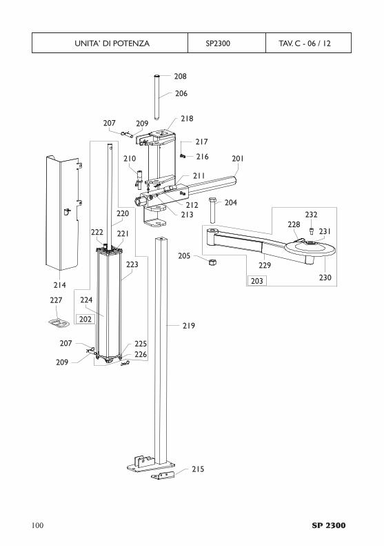
100 SP 2300
UNITA’ DI POTENZA SP2300 TAV. C - 06 / 12
201
211
216
217
212213
218
206
208
204
205
219
215
207 209
210
214
228231
230
232
229
220
222 221
223
224
226225
209
207
227
203
202
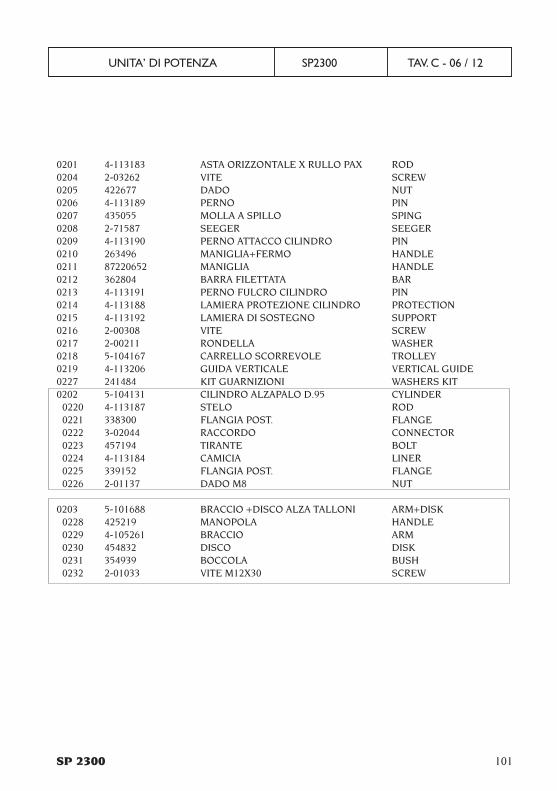
SP 2300 101
UNITA’ DI POTENZA SP2300 TAV. C - 06 / 12
0201 4-113183 ASTA ORIZZONTALE X RULLO PAX ROD0204 2-03262 VITE SCREW0205 422677 DADO NUT0206 4-113189 PERNO PIN0207 435055 MOLLA A SPILLO SPING0208 2-71587 SEEGER SEEGER0209 4-113190 PERNO ATTACCO CILINDRO PIN0210 263496 MANIGLIA+FERMO HANDLE0211 87220652 MANIGLIA HANDLE0212 362804 BARRA FILETTATA BAR0213 4-113191 PERNO FULCRO CILINDRO PIN0214 4-113188 LAMIERA PROTEZIONE CILINDRO PROTECTION0215 4-113192 LAMIERA DI SOSTEGNO SUPPORT0216 2-00308 VITE SCREW0217 2-00211 RONDELLA WASHER0218 5-104167 CARRELLO SCORREVOLE TROLLEY0219 4-113206 GUIDA VERTICALE VERTICAL GUIDE0227 241484 KIT GUARNIZIONI WASHERS KIT0202 5-104131 CILINDRO ALZAPALO D.95 CYLINDER
0220 4-113187 STELO ROD0221 338300 FLANGIA POST. FLANGE0222 3-02044 RACCORDO CONNECTOR0223 457194 TIRANTE BOLT0224 4-113184 CAMICIA LINER0225 339152 FLANGIA POST. FLANGE0226 2-01137 DADO M8 NUT
0203 5-101688 BRACCIO +DISCO ALZA TALLONI ARM+DISK0228 425219 MANOPOLA HANDLE0229 4-105261 BRACCIO ARM0230 454832 DISCO DISK0231 354939 BOCCOLA BUSH0232 2-01033 VITE M12X30 SCREW

102 SP 2300
Note

SP 2300 103
Note

CORGHI S.p.A. - Via per Carpi n.942015 CORREGGIO - R.E. - ITALYTel. ++39 0522 639.111 - Fax ++39 0522 639.150www.corghi.com - [email protected]
UP
T -
Cod
.4-1
1321
2A -0
6/20
12