SK da INDESIGN - reus.hr rucni ventili/FIP - PVC single... · ter of the pipe in mm DN nominal...
7
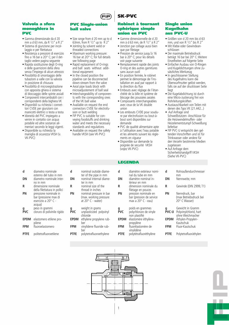
1 SK-PVC LEGENDA Valvola a sfera monoghiera in PVC PVC SingIe-union ball valve Robinet à tournant sphérique simple union en PVC Single union Kugelhahn aus PVC-U • Gamma dimensionale da d 20 mm a d 63 mm, da R 1 /2” a R 2” • Sistema di giunzione per incol- laggio e per filettatura • Resistenza a pressioni di esercizio fino a 16 bar a 2O° C; per il det- taglio vedere pagina seguente • Rapida sostituzione degli O-ring e delle guarnizioni della sfera senza l’impiego di alcun attrezzo • Possibilità di smontaggio delle tubazioni a valle con la valvola in posizione di chiusura • Possibilità di microregistrazione con apposita ghiera e sistema di bloccaggio delle spinte assiali • Componenti intercambiabili con i corrispondenti della bighiera VK • Disponibili su richiesta i connet- tori CVDE per giunzioni con manicotti elettrici o testa a testa • Idoneità del PVC impiegato a venire in contatto con acqua potabile ed altre sostanze ali- mentari secondo le leggi vigenti. • Disponibile su richiesta la maniglia di sicurezza VKSH (v. VK-PVC) • Size range from d 20 mm up to d 63mm, from R 1 /2” up to R 2” • Jointing by solvent weld or threaded connections • Maximum working pressure: 16 bar at 2O° C; for full details see following page • Rapid replacement of O-rings and ball seats without addi- tional equipment • In the closed position the pipeline can be disconnected down-stream from the valve • Axial pipe loads block with microadjustement of ball seal • lnterchangeability of componen- ts with the corresponding ones of the VK ball valve • Available on request the end connectors CVDE for electrofu- sion or butt welding • FIP PVC is suitable for con- veying foodstuffs and drinking water and meets the necessary standards and regulations • Available on request the safety handle VKSH (see VK-PVC) • Gamme dimensionnelle de d 20 mm à d 63 mm, de R 1 /2” à R 2” • Jonction par collage aussi bien que par filetage • Pression de service jusqu’à 16 bar à 20° C; pour les détails voir page suivante • Remplacement rapide des joints O-ring et des autres garnitures sans aucun outil • En position fermée, le robinet permet le démontage de l’ins- tallation en aval par rapport à la direction du flux • Embouts avec réglage de l’étan- chéité de la bille et système de blocage des poussées axiales • Composants interchangeables avec ceux de la VK double union • Les embouts CVDE pour soudu- re par electrofusion ou bout-à- bout sont disponibles sur demande • PVC de qualité alimentaire apte à l’utilisation avec l’eau potable et les aliments suivant les règle- ments en vigueur • Disponible sur demande la poignée de securité VKSH (vojez VK-PVC) • Größen von d 20 mm bis d 63 mm, und von R 1 /2” bis R 2” • Mit Klebe-oder Gewindean- schlüssen • Der maximale Betriebsdruck beträgt 16 bar bei 20° C. Weitere Einzelheiten auf folgente Seite • Einfacher Ausbau von O-Ringen und Kugeldichtungen ohne zu- sätzliches Werkzeug • In geschlossener Stellung des Kugelhahns kann die Überwurfmutter gelöst werden, falls sie auf der drucklosen Seite liegt • Die Kugelabdichtung ist durch eine Micro-Justierung frei von Rohrleitungskräften • Austauschbarkeit von Teilen mit denen des Typs VK (21.442...) • Auf Anfrage sind Schweißstutzen- Anschlüsse für die Heizwendelmuffen- oder Heizelementstumpf-Schweißung lieferbar • FIP PVC-U entspricht den gel- tenden Vorschriften und ist für Trinkwasser oder andere für den Verzehr bestimmte Medien zugelassen • Auf Anfrage dem Sicherheitshandgriff VKSH (Siehe VK-PVC) d diametro nominale esterno del tubo in mm DN diametro nominale inter- no in mm R dimensione nominale della filettatura in pollici PN pressione nominale in bar (pressione max di esercizio a 20° C - acqua) g peso in grammi PVC cloruro di polivinile rigido EPDM elastomero etilene pro- pilene FPM fluoroelastomero PTFE politetrafluoroetilene d nominal outside diame- ter of the pipe in mm DN nominal internal diame- ter in mm R nominal size of the thread in inches PN nominal pressure in bar (max. working pressure at 20° C - water) g weight in grams PVC unplasticized polyvinyl chloride EPDM ethylene propylene rub- ber FPM vinylidene fluoride rub- ber PTFE polytetrafluoroethylene d diamètre extérieur nomi- nal du tube en mm DN diamètre nominaI in- térieur en mm R dimension nominale du filetage en pouces PN pression nominale en bar (pression de service max a 20° C - eau) g poids en grammes PVC polychlorure de vinyle non plastifié EPDM élastomère éthylène- propylène FPM fluorélastomère de vinylidène PTFE polytétrafluoréthylène d Rohraußendurchmesser mm DN Nennweite, mm R Gewinde (DIN 2999, T1) PN Nenndruck, bar (max Betriebsdruck bei 20° C Wasser) g Gewicht in Gramm PVC-U Polyvinylchlorid, hart ohne Weichmacher EPDM Äthylen-Propylen- Kautschuk FPM Fluor-Kautschuk PTFE Polytetrafluoràthylen
Transcript of SK da INDESIGN - reus.hr rucni ventili/FIP - PVC single... · ter of the pipe in mm DN nominal...
1
SK-PVC
LEGENDA
Valvola a sfera monoghiera in PVC
PVC SingIe-union ball valve
Robinet à tournant sphérique simple union en PVC
Single union Kugelhahnaus PVC-U
• Gamma dimensionale da d 20 mm a d 63 mm, da R 1/2” a R 2”
• Sistema di giunzione per incol-laggio e per filettatura
• Resistenza a pressioni di esercizio fino a 16 bar a 2O° C; per il det-taglio vedere pagina seguente
• Rapida sostituzione degli O-ring e delle guarnizioni della sfera senza l’impiego di alcun attrezzo
• Possibilità di smontaggio delle tubazioni a valle con la valvola in posizione di chiusura
• Possibilità di microregistrazione con apposita ghiera e sistema di bloccaggio delle spinte assiali
• Componenti intercambiabili con i corrispondenti della bighiera VK
• Disponibili su richiesta i connet-tori CVDE per giunzioni con
manicotti elettrici o testa a testa• Idoneità del PVC impiegato a
venire in contatto con acqua potabile ed altre sostanze ali-mentari secondo le leggi vigenti.
• Disponibile su richiesta la maniglia di sicurezza VKSH (v. VK-PVC)
• Size range from d 20 mm up to d 63mm, from R 1/2” up to R 2”
• Jointing by solvent weld or threaded connections
• Maximum working pressure: 16 bar at 2O° C; for full details
see following page• Rapid replacement of O-rings
and ball seats without addi-tional equipment
• In the closed position the pipeline can be disconnected
down-stream from the valve• Axial pipe loads block with microadjustement of ball seal• lnterchangeability of componen-
ts with the corresponding ones of the VK ball valve
• Available on request the end connectors CVDE for electrofu-sion or butt welding
• FIP PVC is suitable for con-veying foodstuffs and drinking water and meets the necessary standards and regulations
• Available on request the safety handle VKSH (see VK-PVC)
• Gamme dimensionnelle de d 20 mm à d 63 mm, de R 1/2” à R 2”
• Jonction par collage aussi bien que par filetage
• Pression de service jusqu’à 16 bar à 20° C; pour les détails voir page suivante
• Remplacement rapide des joints O-ring et des autres garnitures sans aucun outil
• En position fermée, le robinet permet le démontage de l’ins-tallation en aval par rapport à la direction du flux
• Embouts avec réglage de l’étan-chéité de la bille et système de blocage des poussées axiales
• Composants interchangeables avec ceux de la VK double union
• Les embouts CVDE pour soudu-re par electrofusion ou bout-à-bout sont disponibles sur
demande• PVC de qualité alimentaire apte
à l’utilisation avec l’eau potable et les aliments suivant les règle-ments en vigueur
• Disponible sur demande la poignée de securité VKSH (vojez VK-PVC)
• Größen von d 20 mm bis d 63 mm, und von R 1/2” bis R 2”
• Mit Klebe-oder Gewindean-schlüssen
• Der maximale Betriebsdruck beträgt 16 bar bei 20° C. Weitere Einzelheiten auf folgente Seite
• Einfacher Ausbau von O-Ringen und Kugeldichtungen ohne zu-sätzliches Werkzeug
• In geschlossener Stellung des Kugelhahns kann die Überwurfmutter gelöst werden, falls sie auf der drucklosen Seite liegt
• Die Kugelabdichtung ist durch eine Micro-Justierung frei von Rohrleitungskräften
• Austauschbarkeit von Teilen mit denen des Typs VK (21.442...)
• Auf Anfrage sind Schweißstutzen- Anschlüsse für die Heizwendelmuffen- oder Heizelementstumpf-Schweißung lieferbar
• FIP PVC-U entspricht den gel-tenden Vorschriften und ist für Trinkwasser oder andere für den Verzehr bestimmte Medien zugelassen
• Auf Anfrage dem Sicherheitshandgriff VKSH (Siehe VK-PVC)
d diametro nominale esterno del tubo in mm
DN diametro nominale inter-no in mm
R dimensione nominale della filettatura in pollici
PN pressione nominale in bar (pressione max di esercizio a 20° C -
acqua)g peso in grammiPVC cloruro di polivinile rigido
EPDM elastomero etilene pro-pilene
FPM fluoroelastomero
PTFE politetrafluoroetilene
d nominal outside diame-ter of the pipe in mm
DN nominal internal diame-ter in mm
R nominal size of the thread in inches
PN nominal pressure in bar (max. working pressure
at 20° C - water)
g weight in gramsPVC unplasticized polyvinyl chlorideEPDM ethylene propylene rub-
ber FPM vinylidene fluoride rub-
ber PTFE polytetrafluoroethylene
d diamètre extérieur nomi-nal du tube en mm
DN diamètre nominaI in-térieur en mm
R dimension nominale du filetage en pouces
PN pression nominale en bar (pression de service max a 20° C - eau)
g poids en grammesPVC polychlorure de vinyle
non plastifiéEPDM élastomère éthylène-
propylèneFPM fluorélastomère de
vinylidènePTFE polytétrafluoréthylène
d Rohraußendurchmesser mmDN Nennweite, mm
R Gewinde (DIN 2999, T1)
PN Nenndruck, bar (max Betriebsdruck bei 20° C Wasser)
g Gewicht in GrammPVC-U Polyvinylchlorid, hart
ohne WeichmacherEPDM Äthylen-Propylen-
Kautschuk FPM Fluor-Kautschuk
PTFE Polytetrafluoràthylen

2
SK-PVC
Dati Tecnici
2
4
Technical Data
Données Techniques
Technische Daten
Coppia di manovra alla massima pressione di esercizio
Max torque at maximum working pressure
Couple de manoeuvre à la pres-sion maximale de service
Betätigungsmomente
Diagramma delle perdite di carico Pressure lost chart Table de perte de charge Druckverlust-Diagramm
Variazione della pressione in fun-zione della temperatura per acqua o fluidi non pericolosi nei confron-ti dei quali il PVC é classificato CHIMICAMENTE RESISTENTE. Vedere il prospetto “Guida alla resistenza chimica”. In altri casi é richiesta un’adeguata diminuzione della pressione nominale PN. 50 anni secondo DIN 3441.
Pressure/temperature rating for water and harmless fluids to which PVC is RESISTANT. See “A guide to chemical resistance”. In other cases a reduction of the rated PN is required.50 years according to DIN 3441
Variation de la pression en fonction de la température pour l’eau et les fluides non agressifs pour lequels le PVC est considéré CHIMIQUEMENT RESISTANT. Voir “Guide de résistance chimique”. Pour les autres cas une diminution du PN est nécessaire. 50 années selon DIN 3441.
Druck/Temperatur-Diagramm für Wasser und ungefährliche Medien gegen die PVC beständig ist. Siehe Beständigkeitsliste. In allen anderen Fällen ist eine entsprechende Reduzierung der Druckstufe erforderlich.50 Jahre nach DIN 3441.
Coefficiente di flusso kv100 Per coefficiente di flusso kv100 si intende la portata Q in litri al mi-nuto di acqua a 20° C che genera una perdita di carico Δ p = 1 bar per una determinata apertura della valvola.I valori kv100 indicati in tabella si intendono per valvola completa-mente aperta.
Flow coefficient kv100 kv100 is the number of litres per minute of water at a temperature of 20° C that will flow through a valve with a one-bar pressure differential at a specified rate. The kv100 values shown in the table are calculated with the valve completely open.
Coefficient de débit kv100 kv100 est le nombre de litres par minute d’eau, à une température de 20° C, qui s’écoule dans une vanne de régulation avec une pression différentielle de 1 bar, à une vitesse donnée. Les valeurs kv100 indiquées sur la table sont évaluées lorsque le robinet est entièrement ouvert.
kv100-WerteDer kv100 - Wert nennt den Durchsatz in I/min für Wasser bei 20° C und einem Δ p von 1 bar bei völlig geöffnetem Ventil.
3225
770
2015
200
2520
385
dDN
kv100
4032
1100
5040
1750
6350
3400
Nm
40
32
28
24
20
16
12
8
4
0
201/2
253/4
321
dR
4011/4
632
5011/2
bar
16
14
12
10
8
6
4
2
0
-20 0 20 40 °C60 10080
bar
1
0,1
0,01
0,001
DN 15
DN 20
100 l/min1000 10000101
DN 25
DN 32
DN 40
DN 50
pres
sione
di e
serc
izio
- wor
king
pre
ssur
epr
essio
n de
ser
vice
- Bet
riebs
druc
k
perd
ita d
i car
ico -
pres
sure
lost
- pe
rte d
e ch
arge
- Dr
uckv
erlu
st
portata - flow rate- débit - Durchflußmenge
mom
ento
di m
anov
ra -
torq
ue -
coup
le de
man
oeuv
re -
Betä
tigun
gsm
omen
te
temperatura di esercizio - working temperaturetempérature de service - Betriebstemperatur
1
3
1
2
3
4

3
SK-PVC
VALVOLA A SFERAcon attacchi femmina per incol-lagglo, serie metrica
BALL VALVEwith metric series plain female ends for solvent welding
ROBINET À TOURNANT SPHÈRIQUE avec embouts femel-les à coller, série métrique
KUGELHAHNmit Klebemuffen21.446.20
Dimensioni Dimensions Dimensions Dimensionen
SKIV
VALVOLA A SFERAcon attacchi femmina, filettatura cilindrica gas
BALL VALVEwith BS parallel threadedfemale ends
ROBINET À TOURNANT SPHERlQUE avec embouts femel-les filetage cylindrique gaz
KUGELHAHNmit Gewindemuffen21.446.10
SKFV
La FIP ha approntato una gamma dl valvole a sfera i cui attacchi sono in accordo con le seguenti norme:Incollaggio: ISO 727; DIN 8063, NF T54-028, UNI EN 1452, BS 4346/1, accoppiabili con tubi secondo ISO 161/1, UNI 7441/75, DIN 8062, NF T54-016, BS 3506, BS 3505Filettatura: UNI ISO 228/1, DIN2999, BS 21.
FIP have produced a complete range of ball valves with couplin-gs complying with the following standards:Solvent welding: ISO 727, DIN 8063, NF T54-028, UNI EN 1452, BS 4346/1, coupling to pipes complying with ISO 161/1, UNI EN 1452, DIN 8062, NF T54-016, BS 3506, BS 3505.Threaded couplings: UNI ISO228/1, DIN 2999, BS 21.
FIP a réalisé une gamme de ro-binets à tournant sphérique dont les embouts sont conformes aux normes suivantes:Encollage: ISO 727, DIN 8063,NF T54-028, UNI EN 1452, BS 4346/1, assemblés avec des tubes selon ISO 161/1, UNI 7441/75, DIN 8062, NF T54-016, BS 3506, BS 3505. Filetage: UNI ISO 228/1, DIN2999, BS 21.
Die Kugelhahnreihe entspricht mit lhren Anschlußmöglichkeiten fol-genden Normen: Klebefittings: ISO 727, DIN 8063, NF T54-028, UNI EN 1452, BS 4346/1, und kann verbunden werden mit Rohren nach ISO 161/1, UNI 7441/75, DIN 8062, NF T54-016, BS 3506, BS 3505.Gewinde: UNI ISO 228/1, DIN2999, BS 21.
L
161922263138
PN
161616161616
DN
152025324050
d
202532405063
L1
161922263540
H
92108117131152183
Z
6070737986
105
E
55667587
100122
E1
283642536176
B
4959667686
100
C
66758597
110134
g
145240325505680
1145
L
1516,319,121,421,425,7
PN
161616161616
DN
152025324050
R
1/2”3/4”
1”1”1/41”1/2
2”
L1
1516,319,121,421,425,7
H
96109121135148177
Z
6676,482,892,2
105,2125,6
E
55667587
100122
E1
283642536176
B
4959667686
100
C
66758597
110134
g
145240335520715
1190
I dati del presente prospetto sono for-niti in buona fede. La FIP non si assu-me alcuna responsabilità su quei dati non direttamente derivati da nor-me internazionali. La FIP si riserva di apportarvi qualsiasi modifica.
The data given in this leaflet are offered in good faith. No liability can be accepted concerning technical data that are not directly covered by recognized international standards. FIP reserved the right to carry out any modification to the products shown in this leaflet.
Les données contenues dans cette brochure sont fournies de bonne foi. FIP n’assume aucune responsabilité pour les données qui ne dérivent pas directement des normes internationa-les. FIP garde le droit d’apporter toute modification aux produits présentés dans cette brochure.
Alle Daten dieser Druckschrift wurden nach bestem Wissen angegeben, je-doch besteht keine Verbindlichkeit, sofern sie nicht direkt internationa-len Normen entnommen wurden. Die Än-derung von Maßen oder Ausführungen bleibt FIP vorbehalten.

4
SK-PVC
VALVOLA A SFERAcon attacchi femmina per incol-laggio, serie BS
BALL VALVEwith BS series plain female ends for solvent welding
ROBINET À TOURNANT SPHERIQUEavec embouts femelles à coller, série BS
KUGELHAHNmit Klebemuffen nach BS
SKLV
VALVOLA A SFERAcon attacchi femmina per incollaggio, serie JIS
BALL VALVEwith JIS series plain female ends for solvent welding
ROBINET À TOURNANT SPHERIQUEavec embouts femelles à coller série JIS
KUGELHAHNmit Klebemuffen JIS
SKJV
VALVOLA A SFERAcon attacchi femmina filettatura JIS standard
BALL VALVEwith JIS standard threaded fema-le ends
ROBINET À TOURNANTSPHERIQUE avec embouts femelles, filetage JIS standard
KUGELHAHNmit Gewindemuffen JIS standard
SKGV
L
26303540445563
PN
16161616161616
d
18,422,426,432,538,648,760,8
DN
13152025324050
L1
26303540445563
H
117117132148167196231
Z
655762687986
105
E
5555667587
100122
E1
28283642536176
B
494959667686
100
C
6666758597
110134
g
110105165215385580955
L
161922252631
PN
161616161616
DN
152025324050
R
1/2”3/4”
1”1”1/41”1/2
2”
L1
161922252631
H
92108117131152183
Z
60707381
100121
E
55667587
100122
E1
283642536176
B
4959667686
100
C
66758597
110134
g
105165215385580955
L
16,519
22,5263036
PN
161616161616
DN
152025324050
R
1/2”3/4”
1”1”1/41”1/2
2”
L1
16,519,522,5
273139
H
92108117131152183
Z
5969,5
727891
108
E
55667587
100122
E1
283642536176
B
4959667686
100
C
66758597
110134
g
140240325510680
1180

5
SK-PVC
1) Svitare la ghiera (13) e inserirla sul tratto di tubo.
2) Procedere all’incollaggio o avvitamento del manicotto (12) sul medesimo tratto di tubo.
3) Posizionare il corpo valvola (7) tramite avvitamento o incollag-gio sul secondo tratto di tubo.
4) Serrare la ghiera al corpo valvola fino a raggiungere la pefetta tenuta della valvola.
• In caso di utilizzo di liquidi vola-tili come per esempio Idrogeno Perossido (H2O2) o Ipoclorito di Sodio (NaClO) si consiglia per ragioni di sicurezza di contattare il servizio tecnico. Tali liquidi, vaporizzando, potrebbero creare pericolose sovrapressioni nella zona tra cassa e sfera.
1) Unscrew the union nut (13) and slide it onto the pipe.2) Solvent weld or screw the valve
end connector (12) onto the same pipe end.
3) Solvent weld or screw the valve body (7) onto the other pipe end where the valve is to be fitted.
4) Tighten the union nut on the valve body to achieve an
optimum valve operation with perfect sealing on the valve seats.
• For safety reasons please con-tact the technical service when using volatile liquids such as hydrogen peroxide (H2O2) and Sodium Hypoclorite (NaClO). These liquids may vaporize with a dangerous pressure increase in the dead space between the ball and the body.
1) Dévisser l’écrou-union (13) et l’insérer sur le tube.
2) Procéder à l’encollage ou visser le collet (12) de raccordement sur ce même tube.
3) Positionner le corps (7) par vissage ou encollage sur l’autre partie du tube.
4) Serrer l’écrou progressivement sur le corps júsqu’au moment où l’on obtient une parfaite étanchéité du robinet.
• Pour raisons de súreté nous vous prions de contacter le ser-vice technique en cas de fluides volatiles comme hydrogène peroxyde (H2O2) et Sodium Hypoclorite (NaCIO). Les liquides peuvent vaporiser avec une dangereuse augmentation de la pression entre la sphère et le corps.
1) Die Überwurfmutter (13) wird abgeschraubt und auf die Rohrleitung geschoben.
2) Das Anschlußteil (12) wird je nach Ausführung mit demsel-ben Leitungsteil verklebt oder verschraubt.
3) Das Gehäuse (7) ist entspre-chend mit dem anderen Lei-tungsende zu verbinden.
4) Die Überwurfmutter (13) wird aufgeschraubt und so weit angezogen, daß eine optimale Abdichtung erreicht wird.
• Für Sicherheitsfragen, wenden Sie sich bitte an den technischen Verkauf, wenn Sie flüchtige Medien wie Wasserstoffperoxid (H2O2) oder Natrium Hypoclorit (NaCIO) verwenden: die Medien können verdampfen mit einer gefährlichen Druckerhöhung in dem Totenraum zwischen der Kugel und dem Gehäuse.
Installazione sull’impianto
Connection to the system
Montage sur l’installation
Einbau in eine Leitung
1) Isolare la valvola dalla linea.2) Svitare completamente la ghie-
ra (13) e spostarla sul tratto di tubo.
3) Estrarre dalla maniglia (2) l’ap-posito inserto (1) ed introdurre le due sporgenze nelle corri-spondenti aperture dell’anello di fermo, parte integrante del supporto (11), procedendo al suo svitamento con una rota-zione antioraria.
4) Tirare la maniglia (2) verso l’alto ed estrarla dall’asta co-mando (4).
5) Dopo aver portato la valvola in posizione di chiusura, estrarre la sfera (6).
6) Premere sull’asta comando (4) verso l’interno fino ad estrarla dalla cassa.
7) Ovviamente, gli O-ring vanno estratti dalle loro sedi come da esploso.
1) Isolate the valve from the line flow.
2) Unscrew the union nut (13) and move it down the pipe
3) Remove the special insert (1) from the handle (2) and push the two projecting ends into the corresponding recesses of the ball seat stop-ring, part of the support (11), screwing it out by rotating counter-clockwise.
4) Pull the handle (2) upwards to remove it from the valve stem (4).
5) After closing the valve, remove the ball (6).
6) Press the stem (4) to drop through into the valve body.
7) The O-rings can be removed from their grooves, as shown in the exploded view.
1) Intercepter le flux en amont du robinet.
2) Dévisser complètement l’écrou-union (13) et l’insérer sur le tube.
3) Enlever l’outil (1) de la poi-gnée (2) et introduire les deux saillies dans les ouvertures cor-respondantes de la bague de fermeture partie intégrante du support (11) et la devisser par une rotation anti-horaire.
4) Tirer la poignée (2) vers le haut et l’extraire de la tige de ma-noeuvre (4).
5) Après avoir mis le robinet en position de fermeture, extraire la sphère (16).
6) Exercer une pression sur la tige de manoeuvre (4) vers l’intérieur pour la faire sortir du corps.
7) Naturellement les joints O-ring doivent être extraits de leur logement selon le dessin des details.
1) Die Leitung ist an geeigneter Stelle drucklos zu machen und zu entleeren.
2) Die Überwurfmutter (13) ist zu lösen und auf die Rohrleitung zu schieben.
3) Mit dem Handgriff (2) ist die Kugel in die geschlossene Stellung zu bringen. Mit dem Schlüssel-Einsatz (1) ist der Dichtungsträger (11) herauszu-
schrauben.4) Der Handgriff (2) ist von der
Spindel (4) abzuziehen.5) Die Kugel (6) kann nun herau-
sgezogen werden.6) Die Spindel (4) wird in das
Gehäuse (7) gedrückt und kann dann herausgenommen werden.
7) Natürlich sind O-Ringe und Dichtungen, wie in der Explo-sionszeichnung dargestellt, zu demontieren.
Smontaggio Disassembly Démontage Demontage

6
SK-PVC
1) Inserire l’asta comando (4) dall’interno della cassa.2) Inserire la guarnizione in PTFE
(5) nella sede della cassa (7).3) Inserire la sfera (6).4) Inserire nella cassa il supporto
solidale all’anello di fermo (11) servendosi dell’apposito inserto (1) fino a battuta.
5) La maniglia (2) con l’inserto (1) va posizionata sull’asta comando (4).6) Inserire il manicotto (12) e la
ghiera (13) avendo cura che l’O-ring di tenuta di testa (10) non fuoriesca dalla sede.
7) Ovviamente gli O-Ring vanno inseriti nelle loro sedi, come da esploso.
Evitare sempre brusche manovre di chiusura e proteggere la valvo-la da manovre accidentali.
1) lnsert the stem (4) by pressing it upwards inside the valve body
2) Place the PTFE seat (5) in its housing, located in the valve body (7).
3) Insert the ball (6).4) Slide the integral support with
the stop-ring (11) into the val-ve body using the insert (1).
5) Push the handle (2) with the insert (1) onto the stem (4).
6) lnsert the end connector (12) tightening the union-nut (13). Take care that the socket O-ring (10) does not come out of its groove.
7) The O-rings must be inserted in their grooves, as shown in the exploded view.
lt is important to avoid rapid closure of valves to eliminate the possibility of water hammer cau-sing damage to the pipeline.
1) Insérer la tige de manoeuvre (4) en passant par l’intérieur du corps.
2) Insérer la garniture en PFTE (5) dans le siège du corps.
3) Insérer la sphère (6).4) Insérer dans le corps le sup-
port intégrant la bague de fermeture (11).
5) Placer l’outil (1) sur son loge-ment dans la poignée (2) et
la positionner sur la tige de manoeuvre (4).
6) lnsérer le collet (12) et l’écrou-union (13) en ayant soin
que le joint O-ring (10) ne sorte pas de son logement.
7) Naturellement les joints O-ring doivent être extraits de leur logement selon les détails figu-rant sur le dessin.
Il faut faire attention à protéger la vanne par manoeuvres acci-dentales et à ne pas la serrer trop rapidement.
1) Die Spindel (4) wird von der Innenseite des Gehäuses (7) eingebaut.
2) Die PTFE-Dichtung (5) ist im Gehäuse (7) einzusetzen.
3) Danach wird die Kugel (6) eingebracht.4) Der Dichtungsträger (11) wird
in das Gehäuse (7) einge-schraubt.
5) Der Handgriff (2) ist auf die Spindel (4) zu stecken und der Schlüssel-Einsatz (1) kommt an seinen Platz im Handgriff.
6) Das Leitungsende mit dem Anschlußteil (12) kann nun in Position gebracht werden. Mit der Überwurfmutter (13) wird die Verbindung mit dem Ge-häuse hergestellt. Es ist darauf zu achten, daß der O-Ring (10) nicht aus der Nut kommt.
7) Natürlich sind alle O-Ringe und Dichtungen wie dargestellt zu montieren.
Schnelle Schließbetätigungen sind unbedingt zu vermeiden. Ebenso Einbau-Lagen und-Orte, bei denen eine zufällige (unbeabsichtigte) Betätigung erfolgen kann.
Montaggio Assembly Montage Montage
Nota: nelle operazioni di montaggio è consigliabile lubrificare le guarnizioni di tenuta in gomma con olii o grassi idonei (sono sconsigliati gli olii mine-rali in quanto aggrediscono la gomma etilene-propilene).
Note: when assembling the valve components it is advisable to lubricate the O-ring with oil or grease. Do not use mineral oils as they attack EPM rubber.
Note: avant l’opération de montage nous conseillons de lubrifier les joints en caout-chouc avec de l’huile. Nous rappelons que les huiles minérales, agressives pour le caoutchouc éthylè-ne-propylène, ne sont pas conseilleés.
Anmerkung: Bei den Montagearbeiten wird empfohlen, die O-Ringe mit einem geeigneten Fett einzureiben. Keinesfalls Mineralöle oder andere Fette verwen-den, diese greifen EPM an.

7
SK-PVC
Pos.
12
*34
*567
*8*910
*1112
Componenti
inserto maniglia maniglia
guarnizione asta comando asta comando
guarnizione della sfera sferacassa
guarnizione (O-ring) tenuta radiale guarnizione (O-ring) tenuta di testa
supporto della guarnizione della sfera con anello di fermo
manicottoghiera
Q.tà
111121111
111
Materiale
PVCPVC
EPDM PVCPTFEPVCPVC
EPDMEPDM
PVCPVCPVC
Pos.
12
*34
*567
*8*910
*1112
Composants
outil pour démontage poignée
joint de la tige de manoeuvre tige de manoeuvre
garniture de la sphère sphère
corpsjoint du corps (O-ring)
joint du collet (O-ring) support de la garniture de la sphère
avec bague de fermeture collet
écrou-union
Q.té
111121111
111
Materiaux
PVCPVC
EPDM PVCPTFEPVCPVC
EPDMEPDM
PVCPVCPVC
*parti di ricambio
Pos.
12
*34
*567
*8*910
*1112
Components
inserthandle
stem O-ringstem
ball seatball
bodyO-ring radial seal
O-ring socket sealsupport for ball seat with stop ring
end connectorunion nut
Q.ty
111121111111
Material
PVCPVC
EPDM PVCPTFEPVCPVC
EPDMEPDM
PVCPVCPVC
Pos.
12
*34
*567
*8*910
*1112
Benennung
Schlüssel-EinsatzHandgriff
O-RingSpindel
DichtungenKugel
GehäuseO-RingO-Ring
Dichtungsträger mit GewinderingAnschlußteile
Überwurfmutter
Menge
111121111111
Werkstoff
PVC-UPVC-UEPDM PVC-U
PTFEPVC-UPVC-UEPDMEPDM PVC-UPVC-UPVC-U
* pièces de rechange
* spare parts * Ersatzteile