SISTEMA PER CONFERENZE CONFERENCE SYSTEM … · protezioni; quando si fa funzionare un trasduttore...
76
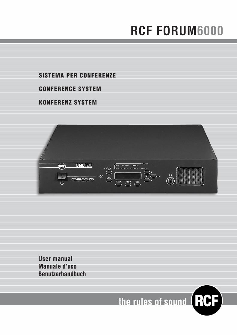
the rules of sound RCF FORUM 6000 SISTEMA PER CONFERENZE CONFERENCE SYSTEM KONFERENZ SYSTEM User manual Manuale d’uso Benutzerhandbuch
Transcript of SISTEMA PER CONFERENZE CONFERENCE SYSTEM … · protezioni; quando si fa funzionare un trasduttore...
the rules of sound
RCF FORUM6000
SISTEMA PER CONFERENZE
CONFERENCE SYSTEM
KONFERENZ SYSTEM
User manualManuale d’usoBenutzerhandbuch
2
ENGLISH
DEU
TSCH
ITALIANO
INDICE - ITALIANO
NOTE SULLA SICUREZZA pag. 4DESCRIZIONE E CARATTERISTICHE PRINCIPALI pag. 6PANNELLO FRONTALE DMU 6100 pag. 7PANNELLO POSTERIORE DMU 6100 pag. 8MENÙ DMU 6100 pag. 10MESSAGGI D’ERRORE pag. 15CONSOLE MICROFONICA DMS 6410 pag. 16DESCRIZIONE DELLA CONSOLE MICROFONICA DMS 6410 pag. 17FUNZIONAMENTO DELLA CONSOLE DMS 6410 SE IMPOSTATA COME “PRESIDENTE” pag. 19FUNZIONAMENTO DELLA CONSOLE SE IMPOSTATA COME “DELEGATO” pag. 21FUNZIONAMENTO DELLA CONSOLE SE IMPOSTATA COME “INTERPRETE” pag. 23TEST DELLE CONSOLE ALL’ACCENSIONE DEL SISTEMA pag. 23CONSOLE NON OPERATIVA (IN “BY-PASS” ) pag. 24CAVO SPECIALE A 10 POLI PER CONSOLE pag. 24CAVO AUDIO BILANCIATO CON CONNETTORI XLR pag. 25ESEMPIO CONNESSIONI pag. 25DATI TECNICI pag. 26
INDEX - ENGLISH
IMPORTANT NOTES page 28DESCRIPTION AND MAIN FEATURES page 30DMU 6100 FRONT PANEL page 31DMU 6100 REAR PANEL page 32DMU 6100 SOFTWARE MENUS page 34ERROR MESSAGES page 39DMS 6410 MICROPHONE CONSOLE page 40DMS 6410 MICROPHONE CONSOLE DESCRIPTION page 41DMS 6410 MICROPHONE CONSOLE SET TO “CHAIRMAN” page 43DMS 6410 MICROPHONE CONSOLE SET TO “DELEGATE” page 45DMS 6410 MICROPHONE CONSOLE SET TO “INTERPRETER” page 47CONSOLE CHECK ON REBOOT page 47DMS 6410 MICROPHONE CONSOLE SET TO “BY-PASS” page 48SPECIAL 10 POLE CABLE FOR DMS 6410 CONSOLES page 48XLR CONNECTORS (BALANCED SIGNAL) page 49CONNECTION INDICATIVE EXAMPLE page 49SPECIFICATIONS page 50

3
ENGLISH
DEU
TSCH
ITALIA
NOINDEX - DEUTSCH
Anmerkungen zur Sicherheit page 52Beschreibungen und Haupteigenschaften page 54Vorderes Paneel DMU 6100 page 55Hinteres Paneel DMU 6100 page 56Menü DMU 6100 page 58Fehlermeldungen page 63Mikrofonsprechstelle DMS 6410 page 64Beschreibung der Mikrofonsprechstelle DMS 6410 page 65Funktion der Sprechstelle DMS 6410Wenn eingestellt als „Präsident“ page 67Funktion der Sprechstelle, wenn als „Abgeordneter“ eingestellt page 69Funktion der Sprechstelle, wenn als „Dolmetscher“ eingestellt page 71Sprechstellentest bei Anschalten des Systems page 71Nicht betriebsbereite Sprechstelle (in „by-pass“) page 72Spezielles Kabel zu 10 Polen für Sprechstellen page 72Ausgewogenes Audiokabel mit Steckern XLR page 73Beispiel für Anschlüsse page 73Technische Daten page 74
4
ITALIANO
Prima di collegare ed utilizzare questo prodotto, leggere attentamente le istruzioni contenute in questo manuale, il quale è da conservare per riferimenti futuri. Il presente manuale costituisce parte integrante del prodotto e deve accompagnare quest’ultimo anche nei passaggi di proprietà, per permettere al nuovo proprietario di conoscere le modalità d’installazione e d’utilizzo e le avvertenze per la sicurezza.L’installazione e l’utilizzo errati del prodotto esimono la RCF S.p.A. da ogni responsabilità.
ATTENZIONE: per prevenire i rischi di fiamme o scosse elettriche, non esporre mai questo prodotto alla pioggia o all’umidità (salvo il caso in cui sia stato espressamente progettato e costruito per l’uso all’aperto).
AVVERTENZE PER LA SICUREZZA1. Tutte le avvertenze, in particolare quelle relative alla sicurezza, devono essere lette con particolare attenzione, in quanto contengono importanti informazioni.
2.1 ALIMENTAZIONE DIRETTA DA RETEa. La tensione di alimentazione dell’apparecchio ha un valore sufficientemente alto da costituire
un rischio di folgorazione per le persone: non procedere mai all’installazione o connessione dell’apparecchio con l’alimentazione inserita.
b. Prima di alimentare questo prodotto, assicurarsi che tutte le connessioni siano corrette e che la tensione della vostra rete di alimentazione corrisponda quella di targa dell’apparecchio, in caso contrario rivolgetevi ad un rivenditore RCF.
c. Le parti metalliche dell’apparecchio sono collegate a terra tramite il cavo di alimentazione.Un apparecchio avente costruzione di CLASSE I deve essere connesso alla presa di rete con un collegamento alla terra di protezione.
d. Accertarsi che il cavo di alimentazione dell’apparecchio non possa essere calpestato o schiacciato da oggetti, al fine di salvaguardarne la perfetta integrità.
e. Per evitare il rischio di shock elettrici, non aprire mai l’apparecchio: all’interno non vi sono parti che possono essere utilizzate dall’utente.
2.2 ALIMENTAZIONE TRAMITE ALIMENTATORE ESTERNOa. Alimentare il prodotto utilizzando solo l’alimentatore dedicato; verificare che la tensione della
vostra rete corrisponda quella di targa dell’alimentatore e che il valore ed il tipo (continua o alternata) di tensione d’uscita dello stesso corrisponda a quella d’ingresso del prodotto, in caso contrario rivolgersi ad un rivenditore RCF; verificare inoltre che l’alimentatore non sia stato danneggiato da eventuali urti o sovraccarichi.
b. La tensione di rete, alla quale è connesso l’alimentatore, ha un valore sufficientemente alto da costituire un rischio di folgorazione per le persone: prestare attenzione durante la connessione alla rete (es. non effettuarla con le mani bagnate) e non aprire mai l’alimentatore.
c. Accertarsi che il cavo dell’alimentatore non sia o possa essere schiacciato da altri oggetti (prestando particolare attenzione alla parte del cavo vicino alla spina ed al punto dove questo esce dall’alimentatore).
2.3 INFORMAZIONI SULLE BATTERIE • Utilizzare sempre batterie ricaricabili del tipo indicato nel presente manuale.• Verificare che sia rispettata la polarità delle batterie. • Non cortocircuitare le batterie (ad esempio collegando i 2 poli opposti con un filo di metallo). • Smaltire le batterie esaurite negli appositi contenitori, facendo riferimento alle norme di legge
vigenti (nel paese di utilizzo) in materia di ecologia e protezione dell’ambiente.
3. Impedire che oggetti o liquidi entrino all’interno del prodotto, perché potrebbero causare un corto circuito.L’apparecchio non deve essere esposto a stillicidio o a spruzzi d’acqua; nessun oggetto pieno di liquido, quali vasi, deve essere posto sull’apparecchio.
4. Non eseguire sul prodotto interventi / modifiche / riparazioni se non quelle espressamente descritte sul manuale istruzioni.Contattare centri di assistenza autorizzati o personale altamente qualificato quando:
• l’apparecchio non funziona (o funziona in modo anomalo);• il cavo di alimentazione ha subito gravi danni;
IMPORTANTE
5
ITALIA
NO• oggetti o liquidi sono entrati nell’apparecchio;
• l’apparecchio ha subito forti urti.5. Qualora questo prodotto non sia utilizzato per lunghi periodi, togliere la tensione dal cavo di alimentazione (o scollegare l’alimentatore esterno).
6. Nel caso che dal prodotto provengano odori anomali o fumo, spegnerlo immediatamente e togliere la tensione dal cavo di alimentazione (o scollegare l’alimentatore esterno).
7. Non collegare a questo prodotto altri apparecchi e accessori non previsti.Quando è prevista l’installazione sospesa, utilizzare solamente gli appositi punti di ancoraggio e non cercare di appendere questo prodotto tramite elementi non idonei o previsti allo scopo.Verificare inoltre l’idoneità del supporto (parete, soffitto, struttura ecc., al quale è ancorato il prodotto) e dei componenti utilizzati per il fissaggio (tasselli, viti, staffe non fornite da RCF ecc.) che devono garantire la sicurezza dell’impianto / installazione nel tempo, anche considerando, ad esempio, vibrazioni meccaniche normalmente generate da un trasduttore.Per evitare il pericolo di cadute, non sovrapporre fra loro più unità di questo prodotto, quando questa possibilità non è espressamente contemplata dal manuale istruzioni.
8. La RCF S.p.A. raccomanda vivamente che l’installazione di questo prodotto sia eseguita solamente da installatori professionali qualificati (oppure da ditte specializzate) in grado di farla correttamente e certificarla in accordo con le normative vigenti.Tutto il sistema audio dovrà essere in conformità con le norme e le leggi vigenti in materia di impianti elettrici.
9. Sostegni e CarrelliSe previsto, il prodotto va utilizzato solo su carrelli o sostegni consigliati dal produttore. L’insieme apparecchio-sostegno / carrello va mosso con estrema cura. Arresti improvvisi, spinte eccessive e superfici irregolari o inclinate possono provocare il ribaltamento dell’assieme.
10. Vi sono numerosi fattori meccanici ed elettrici da considerare quando si installa un sistema audio professionale (oltre a quelli prettamente acustici, come la pressione sonora, gli angoli di copertura, la risposta in frequenza, ecc.).
11. Perdita dell’uditoL’esposizione ad elevati livelli sonori può provocare la perdita permanente dell’udito. Il livello di pressione acustica pericolosa per l’udito varia sensibilmente da persona a persona e dipende dalla durata dell’esposizione. Per evitare un’esposizione potenzialmente pericolosa ad elevati livelli di pressione acustica, è necessario che chiunque sia sottoposto a tali livelli utilizzi delle adeguate protezioni; quando si fa funzionare un trasduttore in grado di produrre elevati livelli sonori è necessario indossare dei tappi per orecchie o delle cuffie protettive.Consultare i dati tecnici contenuti nel manuale istruzioni per conoscere la massima pressione sonora che i diffusori acustici collegati sono in grado di produrre.
NOTE IMPORTANTIPer evitare fenomeni di rumorosità indotta sui cavi che trasportano segnali dai microfoni o di linea (per esempio 0dB), usare solo cavi schermati ed evitare di posarli nelle vicinanze di:• apparecchiature che producono campi elettromagnetici di forte intensità (per esempio trasformatori di grande di potenza);• cavi di rete;• linee che alimentano altoparlanti.
PRECAUZIONI D’USO• Non ostruire le griglie di ventilazione dell’unità. Collocare il prodotto lontano da fonti di calore e garantire la circolazione dell’aria in corrispondenza delle griglie di aerazione. • Non sovraccaricare questo prodotto per lunghi periodi.• Non forzare mai gli organi di comando (tasti, manopole ecc.).• Non usare solventi, alcool, benzina o altre sostanze volatili per la pulitura delle parti esterne dell’unità.
Sistema audio professionale destinato esclusivamente ad installazione fissa
6
ITALIANO
RCF S.p.A. Vi ringrazia per l’acquisto di questo prodotto, realizzato in modo da garantirne l’affidabilità e prestazioni elevate.
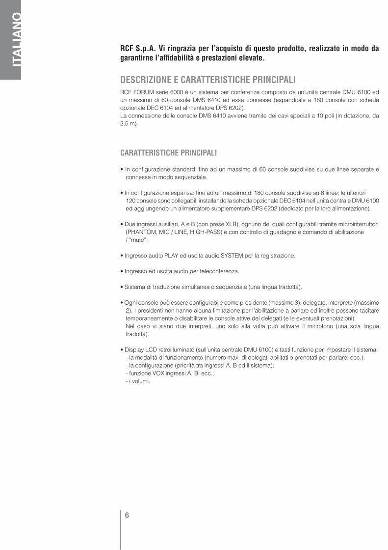
DESCRIZIONE E CARATTERISTICHE PRINCIPALIRCF FORUM serie 6000 è un sistema per conferenze composto da un’unità centrale DMU 6100 ed un massimo di 60 console DMS 6410 ad essa connesse (espandibile a 180 console con scheda opzionale DEC 6104 ed alimentatore DPS 6202).La connessione delle console DMS 6410 avviene tramite dei cavi speciali a 10 poli (in dotazione, da 2,5 m).
CARATTERISTICHE PRINCIPALI
• In configurazione standard: fino ad un massimo di 60 console suddivise su due linee separate e connesse in modo sequenziale.
• In configurazione espansa: fino ad un massimo di 180 console suddivise su 6 linee; le ulteriori 120 console sono collegabili installando la scheda opzionale DEC 6104 nell’unità centrale DMU 6100
ed aggiungendo un alimentatore supplementare DPS 6202 (dedicato per la loro alimentazione).
• Due ingressi ausiliari, A e B (con prese XLR), ognuno dei quali configurabili tramite microinterruttori (PHANTOM, MIC / LINE, HIGH-PASS) e con controllo di guadagno e comando di abilitazione / “mute”.
• Ingresso audio PLAY ed uscita audio SYSTEM per la registrazione.
• Ingresso ed uscita audio per teleconferenza.
• Sistema di traduzione simultanea o sequenziale (una lingua tradotta).
• Ogni console può essere configurabile come presidente (massimo 3), delegato, interprete (massimo 2). I presidenti non hanno alcuna limitazione per l’abilitazione a parlare ed inoltre possono tacitare temporaneamente o disabilitare le console attive dei delegati (e le eventuali prenotazioni).
Nel caso vi siano due interpreti, uno solo alla volta può attivare il microfono (una sola lingua tradotta).
• Display LCD retroilluminato (sull’unità centrale DMU 6100) e tasti funzione per impostare il sistema: - la modalità di funzionamento (numero max. di delegati abilitati o prenotati per parlare; ecc.); - la configurazione (priorità tra ingressi A, B ed il sistema); - funzione VOX ingressi A, B; ecc.; - i volumi.
7
ITALIA
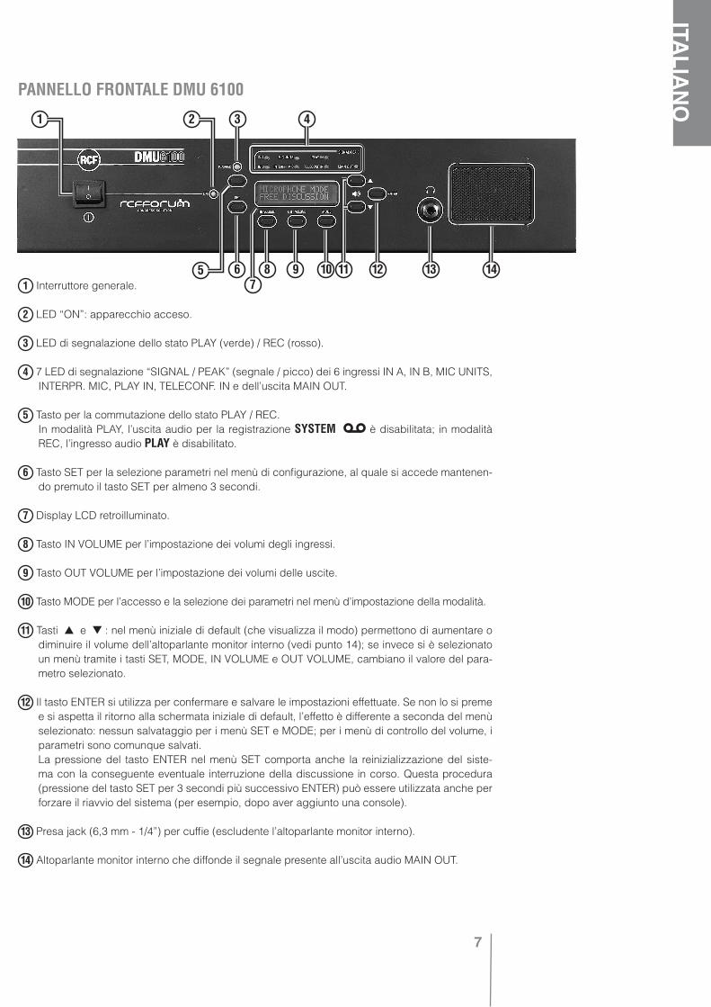
NOPANNELLO FRONTALE DMU 6100
1 Interruttore generale.
2 LED “ON”: apparecchio acceso.
3 LED di segnalazione dello stato PLAY (verde) / REC (rosso).
4 7 LED di segnalazione “SIGNAL / PEAK” (segnale / picco) dei 6 ingressi IN A, IN B, MIC UNITS, INTERPR. MIC, PLAY IN, TELECONF. IN e dell’uscita MAIN OUT.
5 Tasto per la commutazione dello stato PLAY / REC. In modalità PLAY, l’uscita audio per la registrazione SYSTEM è disabilitata; in modalità
REC, l’ingresso audio PLAY è disabilitato.
6 Tasto SET per la selezione parametri nel menù di configurazione, al quale si accede mantenen-do premuto il tasto SET per almeno 3 secondi.
7 Display LCD retroilluminato.
8 Tasto IN VOLUME per l’impostazione dei volumi degli ingressi.
9 Tasto OUT VOLUME per l’impostazione dei volumi delle uscite.
10 Tasto MODE per l’accesso e la selezione dei parametri nel menù d’impostazione della modalità.
11 Tasti e : nel menù iniziale di default (che visualizza il modo) permettono di aumentare o diminuire il volume dell’altoparlante monitor interno (vedi punto 14); se invece si è selezionato un menù tramite i tasti SET, MODE, IN VOLUME e OUT VOLUME, cambiano il valore del para-metro selezionato.
12 Il tasto ENTER si utilizza per confermare e salvare le impostazioni effettuate. Se non lo si preme e si aspetta il ritorno alla schermata iniziale di default, l’effetto è differente a seconda del menù selezionato: nessun salvataggio per i menù SET e MODE; per i menù di controllo del volume, i parametri sono comunque salvati.
La pressione del tasto ENTER nel menù SET comporta anche la reinizializzazione del siste-ma con la conseguente eventuale interruzione della discussione in corso. Questa procedura (pressione del tasto SET per 3 secondi più successivo ENTER) può essere utilizzata anche per forzare il riavvio del sistema (per esempio, dopo aver aggiunto una console).
13 Presa jack (6,3 mm - 1/4”) per cuffie (escludente l’altoparlante monitor interno).
14 Altoparlante monitor interno che diffonde il segnale presente all’uscita audio MAIN OUT.
5
1 2 3 4
6 8 9 107
11 12 13 14
8
ITALIANO
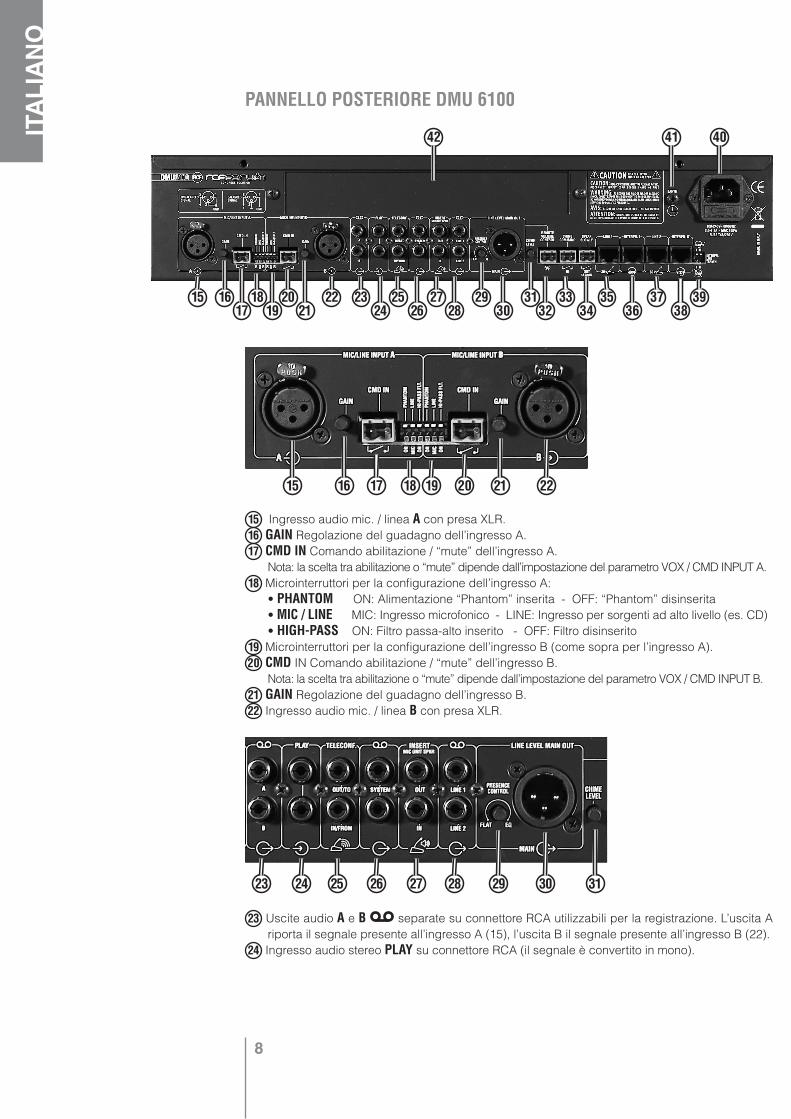
PANNELLO POSTERIORE DMU 6100
15 Ingresso audio mic. / linea A con presa XLR.16 GAIN Regolazione del guadagno dell’ingresso A.17 CMD IN Comando abilitazione / “mute” dell’ingresso A. Nota: la scelta tra abilitazione o “mute” dipende dall’impostazione del parametro VOX / CMD INPUT A.18 Microinterruttori per la configurazione dell’ingresso A: • PHANTOM ON: Alimentazione “Phantom” inserita - OFF: “Phantom” disinserita • MIC / LINE MIC: Ingresso microfonico - LINE: Ingresso per sorgenti ad alto livello (es. CD) • HIGH-PASS ON: Filtro passa-alto inserito - OFF: Filtro disinserito19 Microinterruttori per la configurazione dell’ingresso B (come sopra per l’ingresso A).20 CMD IN Comando abilitazione / “mute” dell’ingresso B. Nota: la scelta tra abilitazione o “mute” dipende dall’impostazione del parametro VOX / CMD INPUT B.21 GAIN Regolazione del guadagno dell’ingresso B.22 Ingresso audio mic. / linea B con presa XLR.
23 Uscite audio A e B separate su connettore RCA utilizzabili per la registrazione. L’uscita A riporta il segnale presente all’ingresso A (15), l’uscita B il segnale presente all’ingresso B (22).
24 Ingresso audio stereo PLAY su connettore RCA (il segnale è convertito in mono).
15 1617
1819
2021
22 2324
2526
2728
2930
3132
3334
3536
3738
39
42 41 40
15 16 17 18 19 20 21 22
23 24 25 26 27 28 29 30 31

9
ITALIA
NO L’ingresso è disabilitato in modalità REC (vedi punto 5: tasto commutazione PLAY / REC).
25 TELECONF. Ingresso IN/FROM ed uscita OUT/TO audio per teleconferenza su connettori RCA.26 Doppia uscita audio mono SYSTEM su connettori RCA utilizzabili per la registrazione del
segnale presente all’uscita MAIN OUT (che dipende dalla configurazione e dai segnali d’in-gresso del sistema). L’uscita è disabilitata in modalità PLAY (vedi punto 5: tasto commutazione PLAY / REC).
27 INSERT MIC UNIT SPKR Ingresso IN / uscita OUT audio con connettori RCA per l’inserimento di un processore di segnale opzionale per gli altoparlanti delle console (senza processore, occorre cortocircuitare l’ingresso e l’uscita tramite un ponticello apposito od un cavo corto con connettori RCA).
28 Uscite audio LINE 1 e LINE 2 su connettori RCA che riportano separatamente i segnali delle due linee (con massimo 30 console ciascuna).
29 PRESENCE CONTROL Controllo toni “presenza” dell’uscita MAIN OUT (FLAT: risposta lineare, segnale non modificato; EQ: segnale equalizzato)
30 Uscita audio principale LINE LEVEL MAIN OUT con connettore XLR.31 CHIME LEVEL Controllo volume del campanello “Chime”.
32 REMOTE VOLUME CONTROL Connettore per il controllo di volume remoto (non fornito; è indica-tivamente consigliato un potenziometro da 22k di tipo B) dell’uscita MAIN OUT.
33 CHIME COMMAND Connettore per il comando esterno di attivazione del campanello (“chime”).Nota: il campanello può essere attivato (tramite l’impostazione ACTIVE del parametro CHIME ON
CHAIRM nel menù di configurazione SET) anche in caso di priorità da parte di un presidente.34 SPEAK SLOWLY Uscita “SPEAK SLOWLY” (“parlate lentamente”) per segnalazione tramite contat-
to pulito interno n.a. (max. 28 V dc; 1 A). L’avviso “SPEAK SLOWLY” viene segnalato tramite il LED giallo lampeggiante alle console quando si dà l’apposito comando dalle console interpreti.
35 LINE 1 Ingresso della prima linea composta da max. 30 console.36 INTERPR.I Ingresso per la prima console interprete.37 LINE 2 Ingresso della seconda linea composta da max. 30 console.38 INTERPR.II Ingresso per la seconda console interprete.39 INTERPR. LINE TERMIN. Microinterruttori I e II per l’abilitazione degli ingressi INTERPR.I ed INTERPR.II.
console interprete presente console interprete assente
40 Connettore con fusibile per l’alimentazione da rete (100÷240 V ac).41 Morsetto per la messa a terra dell’apparecchio.42 Spazio riservato alla scheda opzionale DEC 6104.
32 33 34 35 36 37 38 39
10
ITALIANO
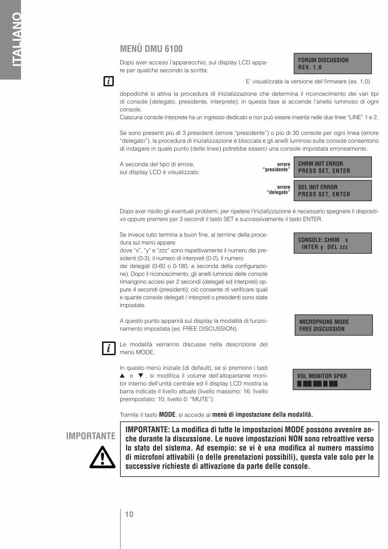
MENÙ DMU 6100Dopo aver acceso l’apparecchio, sul display LCD appa-re per qualche secondo la scritta:
dopodiché si attiva la procedura di inizializzazione che determina il riconoscimento dei vari tipi di console (delegato, presidente, interprete); in questa fase si accende l’anello luminoso di ogni console. Ciascuna console interprete ha un ingresso dedicato e non può essere inserita nelle due linee “LINE” 1 e 2.
Se sono presenti più di 3 presidenti (errore “presidente”) o più di 30 console per ogni linea (errore “delegato”), la procedura di inizializzazione è bloccata e gli anelli luminosi sulle console consentono di indagare in quale punto (delle linee) potrebbe esserci una console impostata erroneamente.
A seconda del tipo di errore, sul display LCD è visualizzato:
Dopo aver risolto gli eventuali problemi, per ripetere l’inizializzazione è necessario spegnere il dispositi-vo oppure premere per 3 secondi il tasto SET e successivamente il tasto ENTER.
Se invece tutto termina a buon fine, al termine della proce-dura sul menù appare:dove “x”, “y” e “zzz” sono rispettivamente il numero dei pre-sidenti (0-3), il numero di interpreti (0-2), il numerodei delegati (0-60 o 0-180, a seconda della configurazio-ne). Dopo il riconoscimento, gli anelli luminosi delle console rimangono accesi per 2 secondi (delegati ed interpreti) op-pure 4 secondi (presidenti); ciò consente di verificare quali e quante console delegati / interpreti o presidenti sono state impostate.
A questo punto apparirà sul display la modalità di funzio-namento impostata (es. FREE DISCUSSION).
Le modalità verranno discusse nella descrizione del menù MODE.
In questo menù iniziale (di default), se si premono i tasti e , si modifica il volume dell’altoparlante moni-
tor interno dell’unità centrale ed il display LCD mostra la barra indicate il livello attuale (livello massimo: 16; livello preimpostato: 10; livello 0: “MUTE”):
Tramite il tasto MODE, si accede al menù di impostazione della modalità.
FORUM DISCUSSION REV. 1.0
CHRM INIT ERROR PRESS SET, ENTER
DEL INIT ERROR PRESS SET, ENTER
CONSOLE: CHRM x INTER y DEL zzz
errore “presidente”
errore “delegato”
MICROPHONE MODE FREE DISCUSSION
VOL MONITOR SPKR
IMPORTANTEIMPORTANTE: La modifica di tutte le impostazioni MODE possono avvenire an-che durante la discussione. Le nuove impostazioni NON sono retroattive verso lo stato del sistema. Ad esempio: se vi è una modifica al numero massimo di microfoni attivabili (o delle prenotazioni possibili), questa vale solo per le successive richieste di attivazione da parte delle console.
E’ visualizzata la versione del firmware (es. 1.0)
11
ITALIA
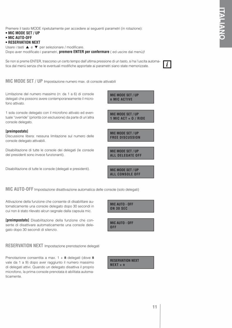
NOPremere il tasto MODE ripetutamente per accedere ai seguenti parametri (in rotazione):
• MIC MODE SET / UP• MIC AUTO-OFF• RESERVATION NEXTUsare i tasti e per selezionare / modificare.Dopo aver modificato i parametri, premere ENTER per confermare ( ed uscire dal menù)!
Se non si preme ENTER, trascorso un certo tempo dall’ultima pressione di un tasto, si ha l’uscita automa-tica dal menù senza che le eventuali modifiche apportate ai parametri siano state memorizzate.
Limitazione del numero massimo (n: da 1 a 6) di console delegati che possono avere contemporaneamente il micro-fono attivato.
1 sola console delegato con il microfono attivato ed even-tuale “override” (priorità con esclusione) da parte di un’altra console delegato.
[preimpostato] Discussione libera: nessuna limitazione sul numero delle console delegato attivabili.
Disabilitazione di tutte le console dei delegati (le console dei presidenti sono invece funzionanti).
Disabilitazione di tutte le console (delegati e presidenti).
Attivazione della funzione che consente di disabilitare au-tomaticamente una console delegato dopo 30 secondi in cui non è stato rilevato alcun segnale dalla capsula mic.
[preimpostato] Disabilitazione della funzione che con-sente di disattivare automaticamente una console dele-gato dopo 30 secondi di silenzio.
Prenotazione consentita a max. 1 + n delegati (dove n vale da 1 a 9) dopo aver raggiunto il numero massimo di delegati attivi. Quando un delegato disattiva il proprio microfono, la prima console prenotata è abilitata automa-ticamente.
MIC MODE SET / UP Impostazione numero max. di console attivabili
MIC MODE SET / UP n MIC ACTIVE
MIC MODE SET / UP 1 MIC ACT + O / RIDE
MIC MODE SET / UP FREE DISCUSSION
MIC MODE SET / UP ALL DELEGATE OFF
MIC MODE SET / UP ALL CONSOLE OFF
MIC AUTO-OFF Impostazione disattivazione automatica delle console (solo delegati)
MIC AUTO - OFF ON 30 SEC
MIC AUTO - OFF OFF
RESERVATION NEXT Impostazione prenotazione delegati
RESERVATION NEXT NEXT + n
12
ITALIANO
Prenotazione consentita ad un solo delegato dopo aver raggiunto il numero massimo di delegati attivi. Quando un delegato disattiva il proprio microfono, la console pre-notata è abilitata automaticamente.
[preimpostato] Disattivazione della funzione di prenota-zione dei delegati.
Tramite il tasto SET, si accede al menù della configurazi-one; premendolo per un istante, sul display LCD appare il testo seguente:
Per accedere al menù, è inizialmente necessario mantenere premuto il tasto SET per almeno 3 secondi. Successivamente, premere il tasto SET ripetutamente per visualizzare i seguenti parametri (in rotazione):
• INTERPRETATION• A & B INPUT MODE• VOX / CMD INPUT A• VOX / CMD INPUT B• CHIME ON CHAIRM• CONSOLE OUT JACKUsare i tasti e per selezionare / modificare.Dopo aver modificato i parametri, premere ENTER per confermare ( ed uscire dal menù)!
Dopo aver premuto ENTER per confermare le nuove impostazioni, viene reinizializzato il sistema ed interrotta la discussione.
Traduzione sequenziale attivata: quando una delle due console interprete chiede l’abilitazione (disabilitando automaticamente l’altra), la lingua tradotta (l’interprete) è inviata alle 3 uscite audio del sistema (linee console, MAIN OUT e l’uscita per teleconferen-za). Quando l’interprete disattiva il proprio microfono, sulle 3 usci-te audio del sistema è nuovamente inviato il segnale miscelato delle console, IN A, IN B, IN PLAY (ed il campanello “Chime”).
Traduzione simultanea attivata: se una delle due console traduttore chiede l’abilitazione (e disabilita l’altra), la lingua tradotta è dispo-nibile solo sulle uscite jack per cuffie delle console (gli altoparlanti interni delle console sono disattivati). Alle altre 2 uscite del sistema (MAIN OUT e l’uscita per teleconferenza), è inviato il segnale misce-lato delle console, IN A, IN B, IN PLAY (ed il campanello “Chime”).
[preimpostato] Traduzione disattivata: alle 3 uscite del siste-ma (linee console, MAIN OUT e teleconferenza) è inviato il segnale miscelato delle console, IN A, IN B,IN PLAY (ed il campanello “Chime”).
RESERVATION NEXT NEXT
RESERVATION NEXT OFF
PRESS KEY 3 sec ENTER INIT SYS
INTERPRETATION Impostazione della modalità di traduzione (sequenziale / simultanea / disattivata)
INTERPRETATION SEQUENTIAL
INTERPRETATION SIMULTANEOUS
INTERPRETATION OFF
IMPORTANTE Scegliendo la modalità di traduzione simultanea, è strettamente necessario collegare un sistema audio di rinforzo (all’uscita “LINE LEVEL MAIN OUT” dell’unità centrale DMU 6100) per permettere l’ascolto della lingua originale.

13
ITALIA
NO
INTERPRETATION Impostazione della modalità di traduzione (sequenziale / simultanea / disattivata)
[preimpostato] Gli ingressi A, B ed il segnale delle con-
sole sono miscelati.
Gli ingressi A e B sono interbloccati tra loro (il primo in-gresso attivato esclude l’altro); il loro segnale è miscelato con quello delle console.
L’ingresso A è prioritario su quello B;il loro segnale è miscelato con quello dei microfoni delle console.
Gli ingressi A e B sono miscelati ed il loro segnale è prio-ritario su quello delle console.
Il segnale delle console è prioritario su quello miscelato degli ingressi A e B.
Il segnale dell’ingresso A è prioritario su quello miscelato composto dall’ingresso B e le console.
VOX : circuito interno che rileva automaticamente la presenza di un segnale audio ad un ingresso.
[preimpostato] L’ingresso A è attivato se il comando esterno viene chiuso (comando = attivazione) o se si rile-va automaticamente il segnale (VOX attivo).
L’ingresso A è attivato se il comando esterno viene chiu-so (comando = attivazione); VOX non attivo.
L’ingresso A è attivato se il comando esterno rimane aperto (comando = “mute”) e se si rileva automaticamen-te il segnale (VOX attivo).
L’ingresso A è attivato se il comando esterno rimane aperto (“command” = “mute”); VOX non attivo.
Le impostazioni sono identi-che a quelle precedenti per l’ingresso MIC / LINE INPUT A (parametro: “VOX / CMD INPUT A”), ma riferite al-l’utilizzo dell’ingresso MIC / LINE INPUT B.
A & B INPUT MODE Impostazione priorità ingressi audio MIC / LINE INPUT A e B
A & B INPUT MODEA mix B mix SYS
A & B INPUT MODE(A lock B) mx SYS
A & B INPUT MODE(A prio B) mx SYS
A & B INPUT MODE(A mx B) prio SYS
A & B INPUT MODESYS prio (A mx B)
VOX / CMD INPUT A Impostazione VOX e comando dell’ingresso audio MIC / LINE INPUT A
VOX / CMD INPUT ACMD ACT, VOX ACT
VOX / CMD INPUT ACMD ACT, VOX OFF
VOX / CMD INPUT ACMD MUTE, VOX ACT
VOX / CMD INPUT ACMD MUTE, VOX OFF
VOX / CMD INPUT B Impostazione VOX e comando dell’ingresso audio MIC / LINE INPUT B
VOX / CMD INPUT BCMD ACT, VOX ACT
VOX / CMD INPUT BCMD ACT, VOX OFF
VOX / CMD INPUT BCMD MUTE, VOX ACT
VOX / CMD INPUT BCMD MUTE, VOX OFF
[preimpostato]
A & B INPUT MODEA prio (B mx SYS)

14
ITALIANO
Il campanello (“chime”) è abilitato sull’intervento con PRIORITA’ di un presidente.
[preimpostato] Il campanello è disabilitato (sull’interven-to con priorità di un presidente).
[preimpostato] Sulle prese jack di ciascuna console, è presente lo stesso segnale di ritorno per l’altoparlante; quando si utilizzano le cuffie, l’altoparlante è disattivato.
Sulle prese jack di ciascuna console, è presente il se-gnale per l’eventuale collegamento di un registratore; l’altoparlante non è disattivato.
Sulle prese jack di ciascuna console non è presente al-cun segnale; l’altoparlante non è disattivato.
Nelle console per interpreti, le prese jack sono sempre in modalità HEADPHONES (uso cuffia), a prescindere dall’impostazione del parametro “CONSOLE OUT JACK”.
Premendo il tasto IN VOLUME, si entra nel menù di impostazione dei volumi degli ingressi; premendolo ripetutamente, si hanno i seguenti parametri (a rotazione). Usare i tasti e per modificare (livello massimo: 16; livello preimpostato: 10; livello 0: “MUTE”).
Volume delle console presidenti e delegati.
Volume delle console interpreti.
Volume dell’ingresso MIC / LINE INPUT A (con presa XLR).
Volume dell’ingresso MIC / LINE INPUT B (con presa XLR).
Volume dell’ingresso PLAY
Volume dell’ingresso per teleconferenza.
CHIME ON CHAIRMACTIVE
CHIME ON CHAIRMOFF
CONSOLE OUT JACKHEADPHONES
CONSOLE OUT JACKRECORDING
CONSOLE OUT JACKDISABLED
VOL CONSOLE MIC
VOL INTERPR. MIC
VOLUME INPUT A
VOLUME INPUT B
VOL IN AUX-PLAY
VOL IN TELECONF.
CONSOLE OUT JACK Impostazione uscite jack delle console (solo delegati e presidenti)
CHIME ON CHAIRM Impostazione segnalazione (campanello) di priorità della console presidente
IMPORTANTE Se è previsto l’utilizzo della traduzione simultanea, mantenere il parametro “CONSOLE OUT JACK” su “HEADPHONES”, altrimenti non sarà possibile ascoltare la lingua tradotta (tramite cuffie).
15
ITALIA
NOPremendo il tasto OUT VOLUME, si entra nel menù di impostazione dei volumi delle uscite; premen-
dolo ripetutamente, si hanno i seguenti parametri (a rotazione). Usare i tasti e per modificare (livello massimo: 16; livello preimpostato: 10; livello 0: “MUTE”).
Volume degli altoparlanti interni delle console.
Volume dell’uscita audio principale MAIN OUT.
Dalla visualizzazione dell’errore, si esce premendo il tasto ENTER.
Durante l’indirizzamento:
CHRM INIT ERROR : sono presenti più di tre console presidenti nel sistema.
DEL INIT ERROR : sono presenti più di 30 console in una linea.
N.B.: se (nell’unità centrale DMU 6100) si invertono le connessioni delle linee delegati/presidenti ed interpreti, il sistema NON è in grado di rilevarlo, quindi non vi è alcuna segnalazione sul display LCD.
Durante il funzionamento:
CONSOLE ERROR : una console presidente o delegato non funziona più (esempio: linea 2, posizione 15).
CONSOLE ERROR : una console interprete non funziona più (esempio: interprete nr.2).
La posizione 1 è la prima console di una linea collegata direttamente all’unità centrale DMU 6100; la posizione 30 è l’ultima console di una linea.
Nel caso vi siano più avarie, il display LCD visualizza comunque un solo errore alla volta dall’accen-sione dell’apparecchio; occorre quindi rimuovere la causa del primo errore per ottenere la visualiz-zazione di quello successivo (se presente) dopo aver riavviato il sistema.
Questo messaggio potrebbe apparire, dopo l’accensione del sistema e la visualizzazione del numero di console, in caso di problemi durante la lettura dell’EEPROM (me-moria interna); in questo caso sono sempre reimpostati i parametri iniziali ed è necessaria l’assistenza tecnica non appena possibile.
Guasti alimentazione e fusibili (è necessaria l’assistenza tecnica):
Guasto alimentazione interna 12 V
VOL CONSOLE SPKR
VOL MAIN OUT
CONSOLE OUT JACK Impostazione uscite jack delle console (solo delegati e presidenti)
MESSAGGI D’ERRORE
CHRM INIT ERRORPRESS SET, ENTER
DEL INIT ERRORPRESS SET, ENTER
CONSOLE ERRORLINE 2 POS.15
CONSOLE ERRORINTERPRETER 2
DEFAULT MODESERVICE REQUIRED
12V POWER FAULTSERVICE REQUIRED
16
ITALIANO
1
Guasto alimentazione interna 24 V
Guasto alimentazione esterna 24 V (DPS 6202)
Guasto fusibile linee console 1 e 2
Guasto fusibile linee console 3 e 4 (DEC 6104)
Guasto fusibile linee console 5 e 6 (DEC 6104)
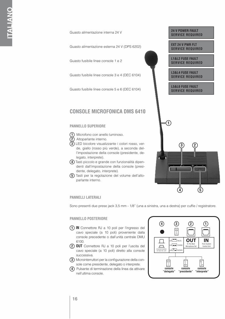
PANNELLO SUPERIORE
1 Microfono con anello luminoso.2 Altoparlante interno.3 LED bicolore visualizzante i colori rosso, ver-
de, giallo (rosso più verde), a seconda del-l’impostazione della console (presidente, de-legato, interprete).
4 Tasti piccolo e grande con funzionalità dipen-denti dall’impostazione della console (presi-dente, delegato, interprete).
5 Tasti per la regolazione del volume dell’alto-parlante interno.
PANNELLI LATERALI
Sono presenti due prese jack 3,5 mm - 1/8” (una a sinistra, una a destra) per cuffie / registratore.
PANNELLO POSTERIORE
1 IN Connettore RJ a 10 poli per l’ingresso del cavo speciale (a 10 poli) proveniente dalla console precedente o dall’unità centrale DMU 6100.
2 OUT Connettore RJ a 10 poli per l’uscita del cavo speciale (a 10 poli) diretto alla console successiva.
3 Microinterruttori per la configurazione della con-sole come presidente, delegato o interprete.
4 Pulsante di terminazione della linea da attivare nell’ultima console.
24 V POWER FAULTSERVICE REQUIRED
CONSOLE MICROFONICA DMS 6410
EXT 24 V PWR FLTSERVICE REQUIRED
L1&L2 FUSE FAULTSERVICE REQUIRED
L3&L4 FUSE FAULTSERVICE REQUIRED
L5&L6 FUSE FAULTSERVICE REQUIRED
4
3 2
5
4 3 2 1
console “delegato”
console “presidente”
console “interprete”
17
ITALIA
NODESCRIZIONE DELLA CONSOLE MICROFONICA DMS 6410
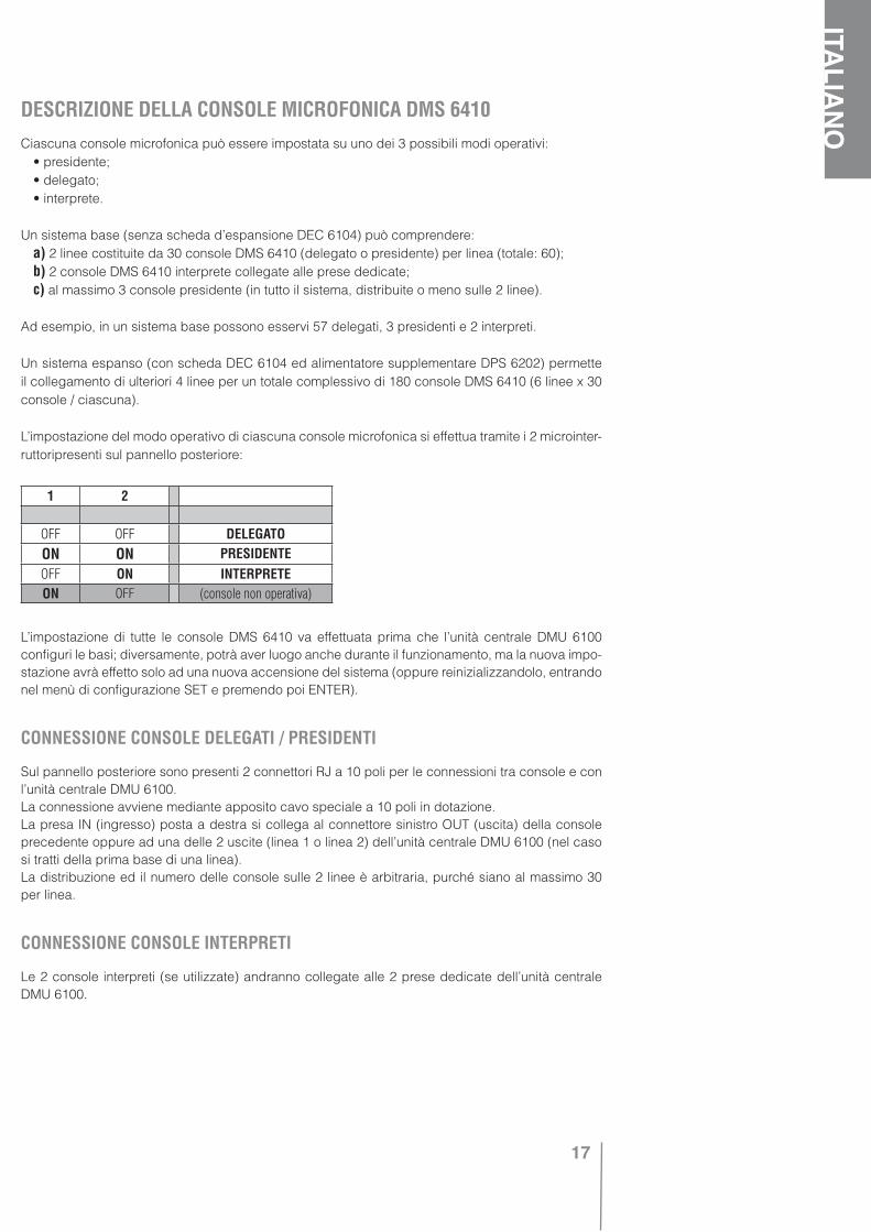
Ciascuna console microfonica può essere impostata su uno dei 3 possibili modi operativi: • presidente; • delegato; • interprete.
Un sistema base (senza scheda d’espansione DEC 6104) può comprendere: a) 2 linee costituite da 30 console DMS 6410 (delegato o presidente) per linea (totale: 60); b) 2 console DMS 6410 interprete collegate alle prese dedicate; c) al massimo 3 console presidente (in tutto il sistema, distribuite o meno sulle 2 linee).
Ad esempio, in un sistema base possono esservi 57 delegati, 3 presidenti e 2 interpreti.
Un sistema espanso (con scheda DEC 6104 ed alimentatore supplementare DPS 6202) permette il collegamento di ulteriori 4 linee per un totale complessivo di 180 console DMS 6410 (6 linee x 30 console / ciascuna).
L’impostazione del modo operativo di ciascuna console microfonica si effettua tramite i 2 microinter-ruttoripresenti sul pannello posteriore:
L’impostazione di tutte le console DMS 6410 va effettuata prima che l’unità centrale DMU 6100 configuri le basi; diversamente, potrà aver luogo anche durante il funzionamento, ma la nuova impo-stazione avrà effetto solo ad una nuova accensione del sistema (oppure reinizializzandolo, entrando nel menù di configurazione SET e premendo poi ENTER).
CONNESSIONE CONSOLE DELEGATI / PRESIDENTI
Sul pannello posteriore sono presenti 2 connettori RJ a 10 poli per le connessioni tra console e con l’unità centrale DMU 6100.La connessione avviene mediante apposito cavo speciale a 10 poli in dotazione.La presa IN (ingresso) posta a destra si collega al connettore sinistro OUT (uscita) della console precedente oppure ad una delle 2 uscite (linea 1 o linea 2) dell’unità centrale DMU 6100 (nel caso si tratti della prima base di una linea).La distribuzione ed il numero delle console sulle 2 linee è arbitraria, purché siano al massimo 30 per linea.
CONNESSIONE CONSOLE INTERPRETI
Le 2 console interpreti (se utilizzate) andranno collegate alle 2 prese dedicate dell’unità centrale DMU 6100.
1 2
OFF OFF DELEGATOON ON PRESIDENTEOFF ON INTERPRETEON OFF (console non operativa)
18
ITALIANO
TERMINAZIONE DELLE LINEEPer una corretta “terminazione” delle linee, procedere come segue:
• Nell’ultima console (delegato o presidente) di una linea, è necessario premere (ON) il relativo inter-ruttore LINE TERMINATION posto sul retro. Sulle restanti console (di ciascuna linea), l’interruttore dovrà essere in posizione OFF (sollevato). Nel caso che una delle console lungo la tratta abbia erroneamente l’interruttore LINE TERMINATION premuto (ON), durante la configurazione tutte le console precedenti saranno riconosciute (accensione anello luminoso), mentre invece le succes-sive non saranno rilevate dall’unità centrale DMU 6100.
• Se si utilizza (almeno) una console interprete, sull’unità centrale DMU 6100 occorre assicurarsi che il relativo microinterruttore di “terminazione” sia in posizione OFF (interprete presente). Sulla con-sole interprete è invece irrilevante premere o meno il relativo interruttore LINE TERMINATION.
• Se NON si utilizza una console interprete, occorre disattivare la relativa linea non utilizzata posizio-nando il relativo microinterruttore posto sull’unità centrale DMU 6100 su ON.
PRESE JACKAi 2 lati della console DMS 6410, sono presenti 2 uscite jack (3,5 mm - 1/8”; una a sinistra, una a destra) Il loro segnale d’uscita dipende dalla configurazione dell’unità centrale DMU 6100 e dalla modalità ope-rativa della base (delegato / presidente / interprete).Le configurazioni possibili sono le seguenti (parametro “CONSOLE OUT JACK” nel menù SET):
• HEADPHONES Il segnale in uscita è ottimizzato per l’uso delle cuffie, inserendole si disattiva l’alto-parlante interno ed il volume può essere regolato con i relativi tasti tra 0 e il massimo valore impo-stato sull’unità centrale DMU 6100.
• RECORDING Il segnale in uscita è ottimizzato per l’uso di un registratore e, inserendo uno qualun-que dei 2 jack, l’altoparlante non è disattivato. Il controllo del volume viene comunque abilitato e può essere impostato tra circa il 30% ed il 100%, ma non può essere portato a zero; l’impostazione del volume sull’unità centrale DMU 6100 non ha effetto.
• DISABLED Non è presente alcun segnale sulle uscite jack (solo per presidenti e delegati). L’altopar-lante interno è comunque funzionante.
Nelle console interpreti, le prese jack sono sempre in modalità HEADPHONES (uso cuffia) a prescin-dere dall’impostazione del parametro “CONSOLE OUT JACK” dell’unità centrale DMU 6100, impo-stazione che ha effetto soltanto per le console presidenti e delegati; pertanto, il volume è sempre regolabile tra zero ed il massimo livello impostato sull’unità centrale.
PANNELLO SUPERIORESono presenti 2 tasti volume, 2 tasti di selezione ed un LED bicolore che hanno una funzionalità dipendente dalla modalità operativa (delegato, presidente, interprete) e dalla configurazione del-l’unità centrale DMU 6100.
ALTOPARLANTE INTERNOI tasti per il controllo del volume ne permettono la regolazione tra zero e il massimo livello impostato sull’unità centrale DMU 6100. L’altoparlante è sempre disinserito durante la traduzione simultanea, quando è attivato il microfono della console, quando sono inserite le cuffie in almeno una delle 2 prese jack se poste in modalità HEADPHONES.
IMPORTANTE Se è previsto l’utilizzo della traduzione simultanea, mantenere il parametro “CONSOLE OUT JACK” su “HEADPHONES”, altrimenti non sarà possibile ascoltare la lingua tradotta (tramite cuffie).

19
ITALIA
NOTASTI VOLUME
Questi tasti permettono di regolare il volume dell’altoparlante interno ed il livello d’uscita delle 2 prese jack.La regolazione può essere effettuata con pressioni successive od in modo continuo tenendo pre-muto il tasto.
TASTI DI SELEZIONE (piccolo e grande)
Vedere i successivi paragrafi inerenti alle varie modalità di funzionamento delle console DMS 6410.
GHIERA MICROFONICA
La ghiera è dotata di un anello luminoso rosso indicante l’attivazione del microfono.
Il presidente non è soggetto all’eventuale limitazione del numero di microfoni aperti contemporaneamen-te. L’attivazione del microfono è possibile anche quando un altro presidente sta utilizzando le funzioni di priorità e disattivazione delle console dei delegati.
Non è possibile attivare il microfono se l’unità centrale non ha rilevato la console oppure se tutte le con-sole presidente e delegato sono disabilitate tramite il parametro MIC MODE SET/UP dell’unità centrale.
• Tasto grande A ( funzionamento NORMALE) : attiva il microfono della console, si accendono il LED rosso e l’anello luminoso del microfono. L’attivazione del microfono è momentanea quando il tasto è mantenuto premuto oppure stabile se il tasto è pigiato una sola volta per un istante. Se rilasciato (o premuto di nuovo per un istante, in caso d’inserzione stabile), si disattiva il microfono (il LED rosso e l’anello luminoso del microfono si spengono).
Se il microfono è già stato attivato in modo stabile mediante una breve pressione del tasto A, è comun-que possibile passare ad un’attivazione momentanea pigiandolo di nuovo e tenendolo premuto.
• Tasto piccolo B ( PRIORITA’ ) : attiva il microfono della console con la priorità sui delegati, si accen-dono il LED verde e l’anello luminoso del microfono, viene diffuso il suono del campanello “chime” (se attivato nel menù di configurazione SET); la priorità consente al presidente di tacitare (per la du-rata dell’intervento) tutti i delegati attivi (ed impedisce agli altri l’attivazione del microfono). Quando la priorità ha termine, i delegati precedentemente tacitati ritornano attivi (se nel frattempo non avevano annullato la selezione), gli altri delegati possono ora richiedere l’abilitazione. Le modalità di attivazione e disattivazione sono analoghe al tasto grande A (vedi sopra).
E’ possibile passare da un’attivazione NORMALE del microfono (tramite il tasto grande A) ad una con PRI-ORITA’ (premendo per un istante con il tasto piccolo B) senza dover prima disattivare. Un’ulteriore pressio-ne momentanea di un tasto (grande A o piccolo B) disattiva il microfono della console presidente.
FUNZIONAMENTO DELLA CONSOLE DMS 6410 SE IMPOSTATA COME “PRESIDENTE”
AB

20
ITALIANO
• Premendo entrambi i tasti (A + B ) contemporaneamente, oltre ad ottenere la PRIORITA’, si effet-tua la disattivazione forzata di tutti i delegati precedentemente attivati (RESET) e si impedisce l’attivazione agli altri, evento segnalato dall’accensione prima lampeggiante per 3 secondi e poi fissa del LED verde.
E’ possibile passare da un’attivazione NORMALE o con PRIORITA’ a RESET senza dover primadisattivare. Un’ulteriore pressione momentanea di un tasto (grande A o piccolo B) disattiva il micro-fono della console presidente.
Se un presidente ha già attivato la funzione PRIORITA’ (oppure RESET), non è più possibile inserirla anche da un altro presidente.
Se un presidente ha già attivato la funzione RESET, non è più possibile effettuarlo da un altro pre-sidente (è invece sempre possibile effettuare il RESET se gli altri presidenti sono attivati in modo NORMALE o con PRIORITA’).
• Il LED giallo (rosso + verde) lampeggiante (visualizzato solo sui presidenti con microfono attivo): • durante la traduzione simultanea, indica la richiesta dell’interprete di parlare più lentamente; • durante la traduzione sequenziale, indica l’attivazione della console interprete (e quindi il
microfono del presidente è momentaneamente disattivato).
SELEZIONI EFFETTUABILI
A Pressione tasto A. - B Pressione tasto B.
OFF > A > NORMALE > A > OFF
OFF > B > PRIORITÁ > A o B > OFF
OFF > A > NORMALE > B > PRIORITÁ > A o B > OFF
OFF > A + B > RESET > A o B > OFF
OFF > A > NORMALE > A + B > RESET > A o B > OFF
OFF > B > PRIORITÁ > A + B > RESET > A o B > OFF
OFF > A > NORMALE > B > PRIORITÁ > A + B > RESET A o B > OFF
RIEPILOGO SEGNALAZIONI TRAMITE LED
LED ROSSO: il presidente ha il microfono attivo (l’anello luminoso è acceso) in modalità NORMALE.
LED VERDE LAMPEGGIANTE SOLO 3 SECONDI: il presidente ha attivato il RESET.
LED VERDE: il presidente si è inserito con PRIORITA’ (o RESET se preceduto da 3 secondi di lam-peggio del LED stesso).
LED GIALLO LAMPEGGIANTE: l’interprete ha richiesto di parlare lentamente (SPEAK SLOWLY) inmodalità di traduzione simultanea oppure l’interprete è attivo in modalità di traduzione sequenziale (ed il microfono della console presidente è momentaneamente disattivato).
Il LED e l’anello luminoso lampeggiano: la comunicazione con l’unità centrale è interrotta da più di 30 secondi. In tale evenienza, il microfono rimarrà comunque abilitato fino alla disattivazione da parte del presidente e non sarà possibile reinserirlo fino a quando non si sarà ripristinata la comunicazione con l’unità centrale.
21
ITALIA
NO
Il delegato è soggetto all’eventuale limitazione (da 1 a 6, configurabile nel software dell’unità cen-trale DMU 6100, parametro MIC MODE SET/UP del menù MODE) del numero massimo di microfoni aperti contemporaneamente. Se tale limite è già stato raggiunto, non è più possibile l’attivazione di un’altra console delegato. Se il parametro MIC MODE SET/UP è stato impostato su “1 MIC ACT+O/RIDE”(un solo microfono attivo con “override” del successivo), si ha una sola console dele-gato attiva alla volta che è automaticamente disattivata non appena se ne inserisce un’altra.
Non è possibile attivare il microfono se: • un presidente ha effettuato il RESET; • un presidente si è inserito con la PRIORITA’; • l’unità centrale non ha rilevato la console; • tutte le console delegato sono disabilitate tramite il parametro MIC MODE SET/UP dell’unità
centrale.
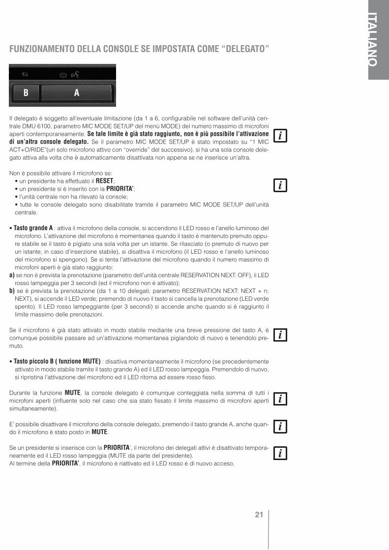
• Tasto grande A : attiva il microfono della console, si accendono il LED rosso e l’anello luminoso del microfono. L’attivazione del microfono è momentanea quando il tasto è mantenuto premuto oppu-re stabile se il tasto è pigiato una sola volta per un istante. Se rilasciato (o premuto di nuovo per un istante, in caso d’inserzione stabile), si disattiva il microfono (il LED rosso e l’anello luminoso del microfono si spengono). Se si tenta l’attivazione del microfono quando il numero massimo di microfoni aperti è già stato raggiunto:
a) se non è prevista la prenotazione (parametro dell’unità centrale RESERVATION NEXT: OFF), il LED rosso lampeggia per 3 secondi (ed il microfono non è attivato);
b) se è prevista la prenotazione (da 1 a 10 delegati; parametro RESERVATION NEXT: NEXT + n; NEXT), si accende il LED verde; premendo di nuovo il tasto si cancella la prenotazione (LED verde spento). Il LED rosso lampeggiante (per 3 secondi) si accende anche quando si è raggiunto il limite massimo delle prenotazioni.
Se il microfono è già stato attivato in modo stabile mediante una breve pressione del tasto A, è comunque possibile passare ad un’attivazione momentanea pigiandolo di nuovo e tenendolo pre-muto.
• Tasto piccolo B ( funzione MUTE) : disattiva momentaneamente il microfono (se precedentemente attivato in modo stabile tramite il tasto grande A) ed il LED rosso lampeggia. Premendolo di nuovo, si ripristina l’attivazione del microfono ed il LED ritorna ad essere rosso fisso.
Durante la funzione MUTE, la console delegato è comunque conteggiata nella somma di tutti i microfoni aperti (influente solo nel caso che sia stato fissato il limite massimo di microfoni aperti simultaneamente).
E’ possibile disattivare il microfono della console delegato, premendo il tasto grande A, anche quan-do il microfono è stato posto in MUTE.
Se un presidente si inserisce con la PRIORITA’, il microfono dei delegati attivi è disattivato tempora-neamente ed il LED rosso lampeggia (MUTE da parte del presidente).Al termine della PRIORITA’, il microfono è riattivato ed il LED rosso è di nuovo acceso.
FUNZIONAMENTO DELLA CONSOLE SE IMPOSTATA COME “DELEGATO”
AB

22
ITALIANO
Se un presidente attiva la funzione RESET, il microfono dei delegati attivi è disattivato, il LED e l’anello luminoso sono spenti; i delegati in attesa (con la prenotazione) sono disattivati (si spegne il LED verde).
• Il LED giallo (rosso + verde) lampeggiante: • durante la traduzione simultanea, indica la richiesta dell’interprete di parlare più lentamente; • durante la traduzione sequenziale, indica l’attivazione della console interprete (e quindi il micro-
fono del delegato è momentaneamente disattivato).Il LED giallo lampeggiante appare solo nelle console delegati con microfono attivo o in MUTE; in
quelle non attive o in prenotazione (con LED verde acceso) non succede nulla.
FUNZIONE MIC AUTO-OFF (SOLO DELEGATI)
Se la funzione MIC AUTO-OFF è stata abilitata (nella configurazione dell’unità centrale), dopo 30 secondi continui (con microfono attivato) in cui non è rilevata la voce del delegato, il relativo micro-fono è disattivato automaticamente.Ogni volta che il delegato riprenderà a parlare negli ultimi 5 secondi a sua disposizione, saranno disponibili ulteriori 10 secondi prima della disattivazione del suo microfono.
Quando il microfono del delegato è momentaneamente disattivato (funzione MUTE inserita da un presidente o dal delegato stesso), la funzione MIC AUTO-OFF non è attiva, così pure durante la modalità di traduzione sequenziale (quando una console interprete è attivata tacitando i delegati).
RIEPILOGO SEGNALAZIONI TRAMITE LED
LED ROSSO LAMPEGGIANTE SOLO 3 SECONDI: si tenta invano l’attivazione del microfono (l’anello luminoso non si accende). Il microfono non si è attivato e non si è nemmeno ottenuta la prenotazio-ne, perché è stato raggiunto il limite massimo di console delegato attivabili contemporaneamente (ed anche la prenotazione non è disponibile) oppure un presidente usufruisce della PRIORITA’ (o ha effettuato il RESET).
LED VERDE: si tenta invano l’attivazione del microfono (l’anello luminoso non si accende) perché è stato raggiunto il limite massimo di console delegato attivabili contemporaneamente, ma il LED verde acceso segnala che la prenotazione è stata accettata.
LED ROSSO: il microfono della console è attivato (l’anello luminoso è acceso).
LED ROSSO LAMPEGGIANTE: la console delegato è stata attivata, ma il microfono è momenta-neamente spento (MUTE). Possibili motivi: è stato premuto il tasto piccolo B (MUTE) oppure un presidente usufruisce della PRIORITA’; in tal caso, il delegato non potrà parlare ma solo disattivare eventualmente il proprio microfono o attendere che il presidente annulli la PRIORITA’.
LED GIALLO LAMPEGGIANTE: l’interprete ha richiesto di parlare lentamente (SPEAK SLOWLY) inmodalità di traduzione simultanea oppure l’interprete è attivo in modalità di traduzione sequenziale (ed il microfono della console delegato è momentaneamente disattivato).
Il LED e l’anello luminoso si spengono senza che il delegato sia intervenuto premendo un tasto:la funzione MIC AUTO-OFF ha automaticamente disinserito il microfono dopo un certo tempo oppu-re un presidente ha effettuato il RESET.
Il LED e l’anello luminoso lampeggiano: la comunicazione con l’unità centrale è interrotta da più di 30 secondi. In tale evenienza, il microfono verrà disabilitato e non sarà possibile reinserirlo fino a quando non si sarà ripristinata la comunicazione con l’unità centrale.
23
ITALIA
NO
Le console per interprete funzionano solamente se una delle 2 modalità di traduzione (sequenziale o simultanea) è stata attivata (tramite l’impostazione del parametro IN-TERPRETATION).
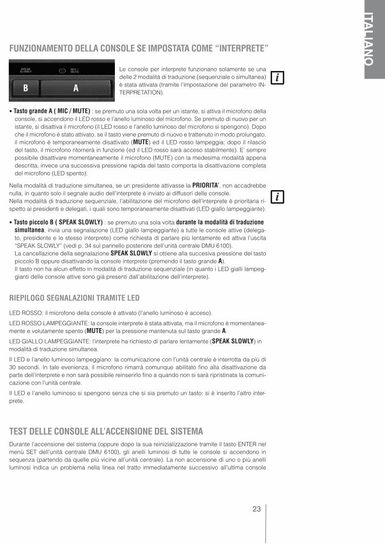
• Tasto grande A ( MIC / MUTE) : se premuto una sola volta per un istante, si attiva il microfono della console, si accendono il LED rosso e l’anello luminoso del microfono. Se premuto di nuovo per un istante, si disattiva il microfono (il LED rosso e l’anello luminoso del microfono si spengono). Dopo che il microfono è stato attivato, se il tasto viene premuto di nuovo e trattenuto in modo prolungato, il microfono è temporaneamente disattivato (MUTE) ed il LED rosso lampeggia; dopo il rilascio del tasto, il microfono ritornerà in funzione (ed il LED rosso sarà acceso stabilmente). E’ sempre possibile disattivare momentaneamente il microfono (MUTE) con la medesima modalità appena descritta, invece una successiva pressione rapida del tasto comporta la disattivazione completa del microfono (LED spento).
Nella modalità di traduzione simultanea, se un presidente attivasse la PRIORITA’, non accadrebbe nulla, in quanto solo il segnale audio dell’interprete è inviato ai diffusori delle console.Nella modalità di traduzione sequenziale, l’abilitazione del microfono dell’interprete è prioritaria ri-spetto ai presidenti e delegati, i quali sono temporaneamente disattivati (LED giallo lampeggiante).
• Tasto piccolo B ( SPEAK SLOWLY) : se premuto una sola volta durante la modalità di traduzione simultanea, invia una segnalazione (LED giallo lampeggiante) a tutte le console attive (delega-
to, presidente e lo stesso interprete) come richiesta di parlare più lentamente ed attiva l’uscita “SPEAK SLOWLY” (vedi p. 34 sul pannello posteriore dell’unità centrale DMU 6100).
La cancellazione della segnalazione SPEAK SLOWLY si ottiene alla succesiva pressione del tasto piccolo B oppure disattivando la console interprete (premendo il tasto grande A).
Il tasto non ha alcun effetto in modalità di traduzione sequenziale (in quanto i LED gialli lampeg-gianti delle console attive sono già presenti dall’abilitazione dell’interprete).
RIEPILOGO SEGNALAZIONI TRAMITE LED
LED ROSSO: il microfono della console è attivato (l’anello luminoso è acceso).
LED ROSSO LAMPEGGIANTE: la console interprete è stata attivata, ma il microfono è momentanea-mente e volutamente spento (MUTE) per la pressione mantenuta sul tasto grande A.
LED GIALLO LAMPEGGIANTE: l’interprete ha richiesto di parlare lentamente (SPEAK SLOWLY) inmodalità di traduzione simultanea.
Il LED e l’anello luminoso lampeggiano: la comunicazione con l’unità centrale è interrotta da più di 30 secondi. In tale evenienza, il microfono rimarrà comunque abilitato fino alla disattivazione da parte dell’interprete e non sarà possibile reinserirlo fino a quando non si sarà ripristinata la comuni-cazione con l’unità centrale.
Il LED e l’anello luminoso si spengono senza che si sia premuto un tasto: si è inserito l’altro inter-prete.
Durante l’accensione del sistema (oppure dopo la sua reinizializzazione tramite il tasto ENTER nel menù SET dell’unità centrale DMU 6100), gli anelli luminosi di tutte le console si accendono in sequenza (partendo da quelle più vicine all’unità centrale). La non accensione di uno o più anelli luminosi indica un problema nella linea nel tratto immediatamente successivo all’ultima console
FUNZIONAMENTO DELLA CONSOLE SE IMPOSTATA COME “INTERPRETE”
TEST DELLE CONSOLE ALL’ACCENSIONE DEL SISTEMA
AB
24
ITALIANO
con l’anello luminoso acceso. Nelle console per delegati ed interpreti, gli anelli luminosi rimangono accesi per 2 secondi, mentre in quelle per presidenti rimangono accesi per 4 secondi; questi tempi possono essere decuplicati (20 secondi per i delegati e gli interpreti, 40 secondi per i presidenti) mantenendo premuto il tasto SET per 3 secondi all’accensione dell’unità centrale DMU 6100 (op-pure dopo aver riavviato il sistema premendo il tasto ENTER nel menù SET).
Nel caso una console non funzioni più correttamente, è sempre consigliabile scollegarla dalla linea; se ciò non è immediatamente possibile (ad esempio, data la distanza tra una console e l’altra e la lunghezza limitata dei cavi), la console guasta può essere resa non operativa pur rimanendo colle-gata alla linea, lasciando quindi transitare i segnali (audio e dati) da e verso le altre console.
Impostazione dei microinterruttori per la disattivazione della console:
E’ necessario riavviare il sistema per rendere effettiva la nuova impostazione.
CONSOLE NON OPERATIVA (IN “BY-PASS”)
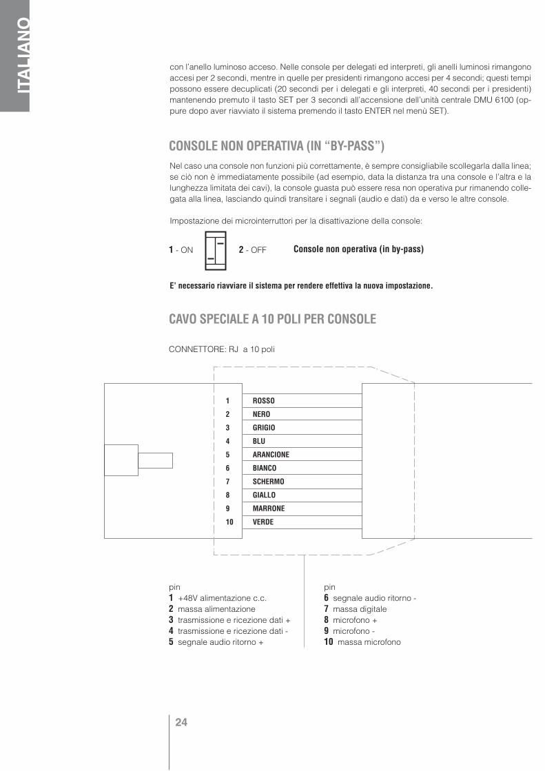
1 - ON 2 - OFF Console non operativa (in by-pass)
CAVO SPECIALE A 10 POLI PER CONSOLE
1 ROSSO
2 NERO
3 GRIGIO
4 BLU
5 ARANCIONE
6 BIANCO
7 SCHERMO
8 GIALLO
9 MARRONE
10 VERDE
CONNETTORE: RJ a 10 poli
pin1 +48V alimentazione c.c.2 massa alimentazione 3 trasmissione e ricezione dati + 4 trasmissione e ricezione dati - 5 segnale audio ritorno +
pin6 segnale audio ritorno -7 massa digitale8 microfono +9 microfono -10 massa microfono
25
ITALIA
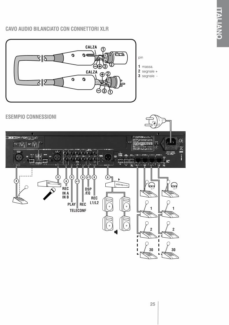
NOCAVO AUDIO BILANCIATO CON CONNETTORI XLR
CONSOLE NON OPERATIVA (IN “BY-PASS”)
CAVO SPECIALE A 10 POLI PER CONSOLE
pin
1 massa.2 segnale + 3 segnale -
ESEMPIO CONNESSIONI
»
»»
»
»
»
»
»
»
»
RECIN AIN B
»
PLAY
TELECONF
REC
DSP/EQ
RECL1/L2
1 1
2 2
30 30
26
ITALIANO
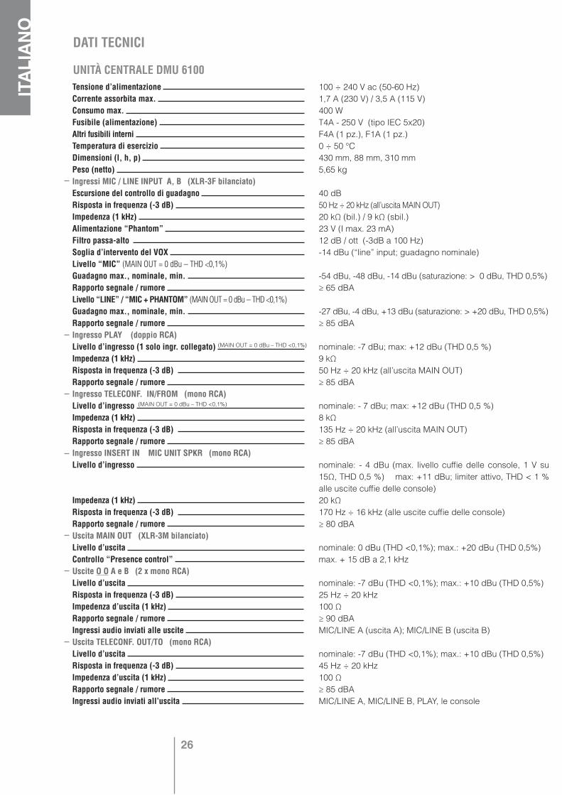
Tensione d’alimentazione Corrente assorbita max. Consumo max. Fusibile (alimentazione) Altri fusibili interni Temperatura di esercizio Dimensioni (l, h, p) Peso (netto) Ingressi MIC / LINE INPUT A, B (XLR-3F bilanciato) Escursione del controllo di guadagno Risposta in frequenza (-3 dB) Impedenza (1 kHz) Alimentazione “Phantom” Filtro passa-alto Soglia d’intervento del VOX Livello “MIC” (MAIN OUT = 0 dBu – THD <0,1%)Guadagno max., nominale, min. Rapporto segnale / rumore Livello “LINE” / “MIC + PHANTOM” (MAIN OUT = 0 dBu – THD <0,1%)Guadagno max., nominale, min. Rapporto segnale / rumore Ingresso PLAY (doppio RCA)Livello d’ingresso (1 solo ingr. collegato) Impedenza (1 kHz) Risposta in frequenza (-3 dB) Rapporto segnale / rumore Ingresso TELECONF. IN/FROM (mono RCA)Livello d’ingresso Impedenza (1 kHz) Risposta in frequenza (-3 dB) Rapporto segnale / rumore Ingresso INSERT IN MIC UNIT SPKR (mono RCA)Livello d’ingresso
Impedenza (1 kHz) Risposta in frequenza (-3 dB) Rapporto segnale / rumore Uscita MAIN OUT (XLR-3M bilanciato)Livello d’uscita Controllo “Presence control” Uscite O O A e B (2 x mono RCA)Livello d’uscita Risposta in frequenza (-3 dB) Impedenza d’uscita (1 kHz) Rapporto segnale / rumore Ingressi audio inviati alle uscite Uscita TELECONF. OUT/TO (mono RCA)Livello d’uscita Risposta in frequenza (-3 dB) Impedenza d’uscita (1 kHz) Rapporto segnale / rumore Ingressi audio inviati all’uscita
100 ÷ 240 V ac (50-60 Hz)1,7 A (230 V) / 3,5 A (115 V)400 WT4A - 250 V (tipo IEC 5x20)F4A (1 pz.), F1A (1 pz.)0 ÷ 50 °C430 mm, 88 mm, 310 mm5,65 kg
40 dB50 Hz ÷ 20 kHz (all’uscita MAIN OUT)20 kΩ (bil.) / 9 kΩ (sbil.)23 V (I max. 23 mA)12 dB / ott (-3dB a 100 Hz)-14 dBu (“line” input; guadagno nominale)
-54 dBu, -48 dBu, -14 dBu (saturazione: > 0 dBu, THD 0,5%)≥ 65 dBA
-27 dBu, -4 dBu, +13 dBu (saturazione: > +20 dBu, THD 0,5%)≥ 85 dBA
nominale: -7 dBu; max: +12 dBu (THD 0,5 %)9 kΩ50 Hz ÷ 20 kHz (all’uscita MAIN OUT)≥ 85 dBA
nominale: - 7 dBu; max: +12 dBu (THD 0,5 %)8 kΩ135 Hz ÷ 20 kHz (all’uscita MAIN OUT)≥ 85 dBA
nominale: - 4 dBu (max. livello cuffie delle console, 1 V su 15Ω, THD 0,5 %) max: +11 dBu; limiter attivo, THD < 1 % alle uscite cuffie delle console)20 kΩ170 Hz ÷ 16 kHz (alle uscite cuffie delle console)≥ 80 dBA
nominale: 0 dBu (THD <0,1%); max.: +20 dBu (THD 0,5%)max. + 15 dB a 2,1 kHz
nominale: -7 dBu (THD <0,1%); max.: +10 dBu (THD 0,5%)25 Hz ÷ 20 kHz100 Ω≥ 90 dBAMIC/LINE A (uscita A); MIC/LINE B (uscita B)
nominale: -7 dBu (THD <0,1%); max.: +10 dBu (THD 0,5%)45 Hz ÷ 20 kHz100 Ω≥ 85 dBAMIC/LINE A, MIC/LINE B, PLAY, le console
DATI TECNICI
UNITÀ CENTRALE DMU 6100
(MAIN OUT = 0 dBu – THD <0,1%)
(MAIN OUT = 0 dBu – THD <0,1%)
27
ITALIA
NO
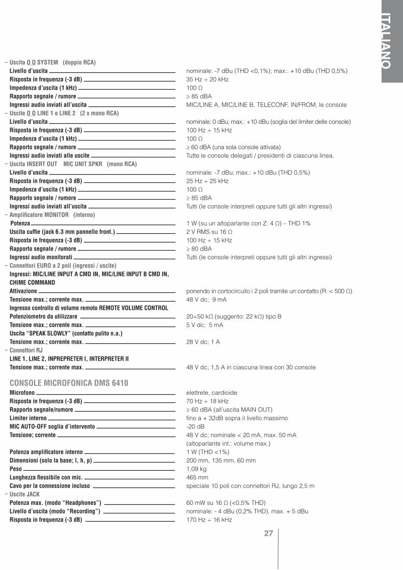
Uscita O O SYSTEM (doppio RCA)Livello d’uscita Risposta in frequenza (-3 dB) Impedenza d’uscita (1 kHz) Rapporto segnale / rumore Ingressi audio inviati all’uscita Uscite O O LINE 1 e LINE 2 (2 x mono RCA)Livello d’uscita Risposta in frequenza (-3 dB) Impedenza d’uscita (1 kHz) Rapporto segnale / rumore Ingressi audio inviati alle uscite Uscita INSERT OUT MIC UNIT SPKR (mono RCA)Livello d’uscita Risposta in frequenza (-3 dB) Impedenza d’uscita (1 kHz) Rapporto segnale / rumore Ingressi audio inviati all’uscita Amplificatore MONITOR (interno) Potenza Uscita cuffie (jack 6.3 mm pannello front.) Risposta in frequenza (-3 dB) Rapporto segnale / rumore Ingressi audio monitorati Connettori EURO a 2 poli (ingressi / uscite)Ingressi: MIC/LINE INPUT A CMD IN, MIC/LINE INPUT B CMD IN, CHIME COMMANDAttivazione Tensione max.; corrente max. Ingresso controllo di volume remoto REMOTE VOLUME CONTROLPotenziometro da utilizzare Tensione max.; corrente max. Uscita “SPEAK SLOWLY” (contatto pulito n.a.)Tensione max.; corrente max. Connettori RJLINE 1, LINE 2, INPREPRETER I, INTERPRETER IITensione max.; corrente max.
Microfono Risposta in frequenza (-3 dB) Rapporto segnale/rumore Limiter interno MIC AUTO-OFF soglia d’intervento Tensione; corrente
Potenza amplificatore interno Dimensioni (solo la base; l, h, p) Peso Lunghezza flessibile con mic. Cavo per la connessione incluso Uscite JACK Potenza max. (modo “Headphones”) Livello d’uscita (modo “Recording”) Risposta in frequenza (-3 dB)
nominale: -7 dBu (THD <0,1%); max.: +10 dBu (THD 0,5%)35 Hz ÷ 20 kHz100 Ω≥ 85 dBAMIC/LINE A, MIC/LINE B, TELECONF. IN/FROM, le console
nominale: 0 dBu; max.: +10 dBu (soglia del limiter delle console)100 Hz ÷ 15 kHz100 Ω≥ 60 dBA (una sola console attivata)Tutte le console delegati / presidenti di ciascuna linea.
nominale: -7 dBu; max.: +10 dBu (THD 0,5%)25 Hz ÷ 25 kHz100 Ω≥ 85 dBATutti (le console interpreti oppure tutti gli altri ingressi)
1 W (su un altoparlante con Z: 4 Ω) – THD 1%2 V RMS su 16 Ω100 Hz ÷ 15 kHz≥ 80 dBATutti (le console interpreti oppure tutti gli altri ingressi)
ponendo in cortocircuito i 2 poli tramite un contatto (R: < 500 Ω)48 V dc; 9 mA
20÷50 kΩ (suggerito: 22 kΩ) tipo B5 V dc; 5 mA
28 V dc; 1 A
48 V dc; 1,5 A in ciascuna linea con 30 console
elettrete, cardioide70 Hz ÷ 18 kHz≥ 60 dBA (all’uscita MAIN OUT)fino a + 32dB sopra il livello massimo-20 dB48 V dc; nominale < 20 mA, max. 50 mA (altoparlante int.: volume max.)1 W (THD <1%)200 mm, 135 mm, 60 mm1,09 kg465 mmspeciale 10 poli con connettori RJ, lungo 2,5 m
60 mW su 16 Ω (<0,5% THD)nominale: - 4 dBu (0,2% THD), max. + 5 dBu170 Hz ÷ 16 kHz
CONSOLE MICROFONICA DMS 6410
28
ENGLISH
Before connecting and using this product, please read this instruction manual carefully and keep it on hand for future reference. The manual is to be considered an integral part of this product and must accompany it when it changes ownership as a reference for correct installation and use as well as for the safety precautions.RCF S.p.A. will not assume any responsibility for the incorrect installation and / or use of this product.WARNING: to prevent the risk of fire or electric shock, never expose this product to rain or humidity (except in case it has been expressly designed and made for outdoor use).
SAFETY PRECAUTIONS1. All the precautions, in particular the safety ones, must be read with special attention, as they provide important information.
2.1 POWER SUPPLY FROM MAINS (direct connection)a. The mains voltage is sufficiently high to involve a risk of electrocution; therefore, never
install or connect this product with the power supply switched on.b. Before powering up, make sure that all the connections have been made correctly and the
voltage of your mains corresponds to the voltage shown on the rating plate on the unit, if not, please contact your RCF dealer.
c. The metallic parts of the unit are earthed by means of the power cable. An apparatus with CLASS I construction shall be connected to a mains socket outlet with a
protective earthing connection.d. Protect the power cable from damage; make sure it is positioned in a way that it cannot be
stepped on or crushed by objects.e. To prevent the risk of electric shock, never open the product: there are no parts inside that
the user needs to access.
2.2 POWER SUPPLY BY MEANS OF AN EXTERNAL ADAPTERa. Use the dedicated adapter only; verify the mains voltage corresponds to the voltage
shown on the adapter rating plate and the adapter output voltage value and type (direct / alternating) corresponds to the product input voltage, if not, please contact your RCF dealer; verify also that the adapter hasn’t been damaged due to possible clashes / hits or overloads.
b. The mains voltage, which the adapter is connected to, is sufficiently high to involve a risk of electrocution: pay attention during the connection (i.e. never do it with wet hands) and never open the adapter.
c. Make sure that the adapter cable is not (or cannot be) stepped on or crushed by other objects (pay particular attention to the cable part near the plug and the point where it leads out from the adapter).
2.3 INFORMATION ABOUT BATTERIES• Use always rechargeable batteries as indicated on present manual.• Verify the batteries’ polarity is correct.• Do NOT short-circuit batteries (i.e. by connecting the 2 poles together with a metallic wire)• Throw empty batteries into dedicated garbage can, according to the present laws (of your
country) about ecology and environment protection.3. Make sure that no objects or liquids can get into this product, as this may cause a short circuit.This apparatus shall not be exposed to dripping or splashing. No objects filled with liquid, such as vases, shall be placed on this apparatus4. Never attempt to carry out any operations, modifications or repairs that are not expressly described in this manual.
Contact your authorized service centre or qualified personnel should any of the following occur:• the product does not function (or functions in an anomalous way);• the power supply cable has been damaged;
IMPORTANT NOTES
29
ENGLISH
• objects or liquids have got into the unit;• the product has been subject to a heavy impact.
5. If this product is not used for a long period, switch it off and disconnect the power cable.
6. If this product begins emitting any strange odours or smoke, switch it off immediately and disconnect the power supply cable.
7. Do not connect this product to any equipment or accessories not foreseen.For suspended installation, only use the dedicated anchoring points and do not try to hang this product by using elements that are unsuitable or not specific for this purpose.Also check the suitability of the support surface to which the product is anchored (wall, ceiling, structure, etc.), and the components used for attachment (screw anchors, screws, brackets not supplied by RCF etc.), which must guarantee the security of the system / installation over time, also considering, for example, the mechanical vibrations normally generated by transducers.To prevent the risk of falling equipment, do not stack multiple units of this product unless this possibility is specified in the instruction manual.
8. RCF S.p.A. strongly recommends this product is only installed by professional qualified installers (or specialised firms) who can ensure correct installation and certify it according to the regulations in force.The entire audio system must comply with the current standards and regulations regarding electrical systems.
9. Supports and trolleysThe equipment should be only used on trolleys or supports, where necessary, that are recommended by the manufacturer. The equipment / support / trolley assembly must be moved with extreme caution. Sudden stops, excessive pushing force and uneven floors may cause the assembly to overturn.
10. There are numerous mechanical and electrical factors to be considered when installing a professional audio system (in addition to those which are strictly acoustic, such as sound pressure, angles of coverage, frequency response, etc.).
11. Hearing lossExposure to high sound levels can cause permanent hearing loss. The acoustic pressure level that leads to hearing loss is different from person to person and depends on the duration of exposure. To prevent potentially dangerous exposure to high levels of acoustic pressure, anyone who is exposed to these levels should use adequate protection devices. When a transducer capable of producing high sound levels is being used, it is therefore necessary to wear ear plugs or protective earphones.See the technical specifications in the instruction manual for the maximum sound pressure the loudspeaker is capable of producing.
IMPORTANT NOTESTo prevent the occurrence of noise on the cables that carry microphone signals or line signals (for example, 0 dB), only use screened cables and avoid running them in the vicinity of:• equipment that produces high-intensity electromagnetic fields (for example, high power transformers);• mains cables;• lines that supply loudspeakers.
OPERATING PRECAUTIONS• Do not obstruct the ventilation grilles of the unit. Situate this product far from any heat sources and always ensure adequate air circulation around the ventilation grilles. • Do not overload this product for extended periods of time.• Never force the control elements (keys, knobs, etc. ).• Do not use solvents, alcohol, benzene or other volatile substances for cleaning the external parts of this product.
Professional audio equipment for fixed installation only
30
ENGLISH
RCF S.p.A. would like to thank you for purchasing this product, which has been designed to guarantee reliability and high performance.
DESCRIPTION AND MAIN FEATURESRCF FORUM 6000 series is a conference system having a central unit DMU 6100, which up to 60 microphone consoles DMS 6410 can be connected to (note: the system can be expanded up to 180 consoles thanks to the optional board DEC 6104 and the additional power supply unit DPS 6202).Consoles DMS 6410 are connected by means of special 10 pole cables (a 2.5 m cable is included for every console).
MAIN FEATURES:
• Standard system: up to 60 consoles DMS 6410 (2 lines; 30 consoles per line connected in daisy-chain).
• Expanded system: up to 180 consoles DMS 6410 (6 lines; 30 consoles per line connected in daisy-chain). The further 120 consoles can be added by installing the optional board DEC 6104 into the central unit DMU 6100 and connecting the external power supply unit DPS 6202.
• 2 aux inputs, A and B, with XLR sockets, each configurable by means of DIP switches (PHANTOM, MIC / LINE, HIGH-PASS) and with a gain control and an enable / mute command.
• Audio input PLAY and audio output SYSTEM for recording.
• Audio input and output for teleconference.
• Simultaneous / sequential translation (1 translated language).
• Each console can be set to 1 of the 3 available modes: chairman (max. 3), delegate, interpreter (max. 2). Chairmen have no limits about their microphone activation and can also mute / disable all delegate consoles (and cancel their bookings).
If 2 interpreters are present, only one will be allowed to speak (1 translated language only).
• Backlit LCD and function keys to enter the software menus and edit: • Operating mode (max. number of activated delegates, max. queue length of the delegates’
booking, etc.) • Configuration (priority level among inputs A, B and the system; VOX function on inputs A, B; etc.) • Volume levels.
31
ENGLISH
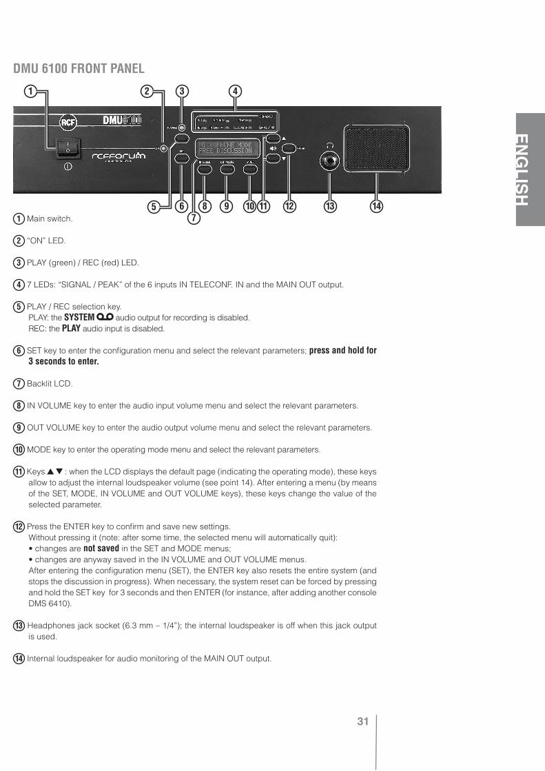
DMU 6100 FRONT PANEL
1 Main switch.
2 “ON” LED.
3 PLAY (green) / REC (red) LED.
4 7 LEDs: “SIGNAL / PEAK” of the 6 inputs IN TELECONF. IN and the MAIN OUT output.
5 PLAY / REC selection key. PLAY: the SYSTEM audio output for recording is disabled. REC: the PLAY audio input is disabled.
6 SET key to enter the configuration menu and select the relevant parameters; press and hold for 3 seconds to enter.
7 Backlit LCD.
8 IN VOLUME key to enter the audio input volume menu and select the relevant parameters.
9 OUT VOLUME key to enter the audio output volume menu and select the relevant parameters.
10 MODE key to enter the operating mode menu and select the relevant parameters.
11 Keys : when the LCD displays the default page (indicating the operating mode), these keys allow to adjust the internal loudspeaker volume (see point 14). After entering a menu (by means of the SET, MODE, IN VOLUME and OUT VOLUME keys), these keys change the value of the selected parameter.
12 Press the ENTER key to confirm and save new settings. Without pressing it (note: after some time, the selected menu will automatically quit): • changes are not saved in the SET and MODE menus; • changes are anyway saved in the IN VOLUME and OUT VOLUME menus. After entering the configuration menu (SET), the ENTER key also resets the entire system (and
stops the discussion in progress). When necessary, the system reset can be forced by pressing and hold the SET key for 3 seconds and then ENTER (for instance, after adding another console DMS 6410).
13 Headphones jack socket (6.3 mm – 1/4”); the internal loudspeaker is off when this jack output is used.
14 Internal loudspeaker for audio monitoring of the MAIN OUT output.
5
1 2 3 4
6 8 9 107
11 12 13 14
32
ENGLISH
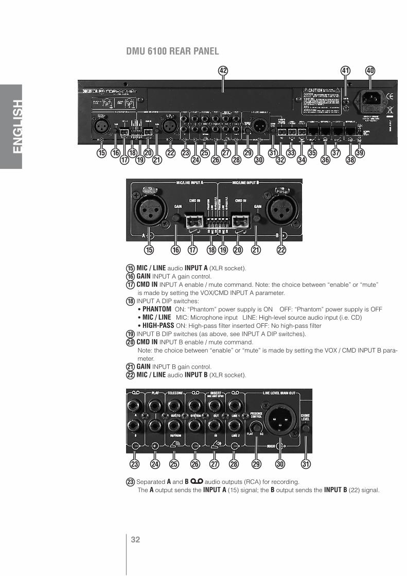
DMU 6100 REAR PANEL
15 MIC / LINE audio INPUT A (XLR socket).16 GAIN INPUT A gain control.17 CMD IN INPUT A enable / mute command. Note: the choice between “enable” or “mute” is made by setting the VOX/CMD INPUT A parameter.18 INPUT A DIP switches: • PHANTOM ON: “Phantom” power supply is ON OFF: “Phantom” power supply is OFF • MIC / LINE MIC: Microphone input LINE: High-level source audio input (i.e. CD) • HIGH-PASS ON: High-pass filter inserted OFF: No high-pass filter19 INPUT B DIP switches (as above, see INPUT A DIP switches).20 CMD IN INPUT B enable / mute command. Note: the choice between “enable” or “mute” is made by setting the VOX / CMD INPUT B para-
meter.21 GAIN INPUT B gain control.22 MIC / LINE audio INPUT B (XLR socket).
23 Separated A and B audio outputs (RCA) for recording. The A output sends the INPUT A (15) signal; the B output sends the INPUT B (22) signal.
15 1617
1819
2021
22 2324
2526
2728
2930
3132
3334
3536
3738
39
42 41 40
15 16 17 18 19 20 21 22
23 24 25 26 27 28 29 30 31
33
ENGLISH
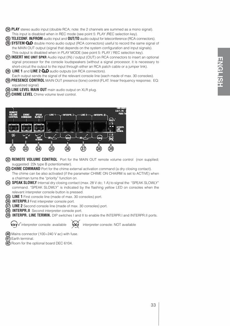
24 PLAY stereo audio input (double RCA; note: the 2 channels are summed as a mono signal). This input is disabled when in REC mode (see point 5: PLAY /REC selection key). 25 TELECONF. IN/FROM audio input and OUT/TO audio output for teleconference (RCA connectors).26 SYSTEM double mono audio output (RCA connectors) useful to record the same signal of
the MAIN OUT output (signal that depends on the system configuration and input signals). This output is disabled when in PLAY MODE (see point 5: PLAY / REC selection key).27 INSERT MIC UNIT SPKR Audio input (IN) / output (OUT) on RCA connectors to insert an optional
signal processor for the console loudspeakers (without a signal processor, it is necessary to short-circuit the output to the input through either an RCA patch cable or a jumper link).
28 LINE 1 and LINE 2 audio outputs (on RCA connectors). Each output sends the signal of the relevant console line (each made of max. 30 consoles).29 PRESENCE CONTROL MAIN OUT presence (tone) control (FLAT: linear frequency response; EQ:
equalized signal)30 LINE LEVEL MAIN OUT main audio output on XLR plug.31 CHIME LEVEL Chime volume level control.
32 REMOTE VOLUME CONTROL Port for the MAIN OUT remote volume control (non supplied; suggested: 22k type B potentiometer).
33 CHIME COMMAND Port for the chime external activation command (a dry closing contact). The chime can be also activated (if the parameter CHIME ON CHAIRM is set to ACTIVE) when
a chairman turns the “priority” function on. 34 SPEAK SLOWLY Internal dry closing contact (max. 28 V dc; 1 A) to signal the “SPEAK SLOWLY”
command. “SPEAK SLOWLY” is indicated by the flashing yellow LED on consoles when the relevant interpreter console button is pressed.
35 LINE 1 First console line (made of max. 30 consoles) port.36 INTERPR.I First interpreter console port.37 LINE 2 Second console line (made of max. 30 consoles) port.38 INTERPR.II Second interpreter console port.39 INTERPR. LINE TERMIN. DIP switches I and II to enable the INTERPR.I and INTERPR.II ports.
interpreter console: available interpreter console: NOT available
40 Mains connector (100÷240 V ac) with fuse.41 Earth terminal.42 Room for the optional board DEC 6104.
32 33 34 35 36 37 38 39
34
ENGLISH
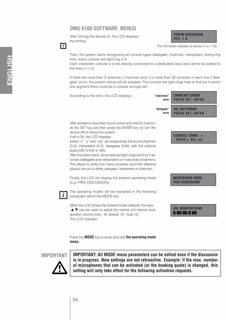
DMU 6100 SOFTWARE MENUS After turning the device on, the LCD displays the writing:
Then, the system starts recognizing all console types (delegate, chairman, interpreter); during this time, every console red light-ring is lit. Each interpreter console is to be directly connected to a dedicated input and cannot be added to the lines L1 / L2.
If there are more than 3 chairmen (“chairman error”) or more than 30 consoles in each line (“dele-gate” error), the system reboot will be stopped. The console red light-rings help to find out in which line segment there could be a console wrongly set.
According to the error, the LCD displays:
After problems have been found, press and hold for 3 secon-ds the SET key and then press the ENTER key (or turn the device off) to reboot the system. If all is OK, the LCD displays:where “x”, “y” and “zzz” are respectively the found chairmen (0-3), interpreters (0-2), delegates (0-60; with the optional board DEC 6104: 0-180). After the initial check, all console red light-rings are lit for 2 se-conds (delegates and interpreters) or 4 seconds (chairmen). This allows to verify how many consoles (and their effective places) are set to either delegate / interpreter or chairman.
Finally, the LCD will display the present operating mode (e.g. FREE DISCUSSION).
The operating modes will be explained in the following paragraph about the MODE key.
When the LCD shows the present mode (default), the keys can be used to adjust the central unit internal loud-speaker volume (max.: 16; default: 10; mute: 0). The LCD displays:
Press the MODE key to enter and edit the operating mode menu.
FORUM DISCUSSION REV. 1.0
CHRM INIT ERROR PRESS SET, ENTER
DEL INIT ERROR PRESS SET, ENTER
CONSOLE: CHRM x INTER y DEL zzz
“chairman” error
“delegate” error
MICROPHONE MODE FREE DISCUSSION
VOL MONITOR SPKR
IMPORTANT IMPORTANT: All MODE menu parameters can be edited even if the discussion is in progress. New settings are not retroactive. Example: if the max. number of microphones that can be activated (or the booking quote) is changed, this setting will only take effect for the following activation requests.
The firmware release is shown (i.e. 1.0)
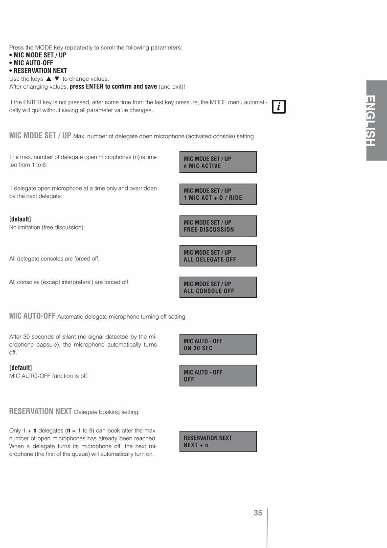
35
ENGLISH
Press the MODE key repeatedly to scroll the following parameters: • MIC MODE SET / UP• MIC AUTO-OFF• RESERVATION NEXTUse the keys to change values.After changing values, press ENTER to confirm and save (and exit)!
If the ENTER key is not pressed, after some time from the last key pressure, the MODE menu automati-cally will quit without saving all parameter value changes..
The max. number of delegate open microphones (n) is limi-ted from 1 to 6.
1 delegate open microphone at a time only and overridden by the next delegate.
[default]No limitation (free discussion).
All delegate consoles are forced off.
All consoles (except interpreters’) are forced off.
After 30 seconds of silent (no signal detected by the mi-crophone capsule), the microphone automatically turns off.
[default]MIC AUTO-OFF function is off.
Only 1 + n delegates (n = 1 to 9) can book after the max. number of open microphones has already been reached. When a delegate turns its microphone off, the next mi-crophone (the first of the queue) will automatically turn on.
MIC MODE SET / UP Max. number of delegate open microphone (activated console) setting
MIC MODE SET / UP n MIC ACTIVE
MIC MODE SET / UP 1 MIC ACT + O / RIDE
MIC MODE SET / UP FREE DISCUSSION
MIC MODE SET / UP ALL DELEGATE OFF
MIC MODE SET / UP ALL CONSOLE OFF
MIC AUTO-OFF Automatic delegate microphone turning off setting
MIC AUTO - OFF ON 30 SEC
MIC AUTO - OFF OFF
RESERVATION NEXT Delegate booking setting
RESERVATION NEXT NEXT + n
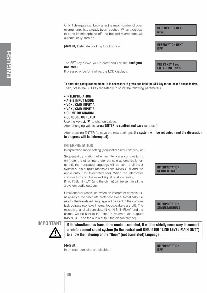
36
ENGLISH
Only 1 delegate can book after the max. number of open microphones has already been reached. When a delega-te turns its microphone off, the booked microphone will automatically turn on.
[default] Delegate booking function is off.
The SET key allows you to enter and edit the configura-tion menu.If pressed once for a while, the LCD displays:
To enter the configuration menu, it is necessary to press and hold the SET key for at least 3 seconds first.Then, press the SET key repeatedly to scroll the following parameters:
• INTERPRETATION• A & B INPUT MODE• VOX / CMD INPUT A• VOX / CMD INPUT B• CHIME ON CHAIRM• CONSOLE OUT JACKUse the keys to change values.After changing values, press ENTER to confirm and save (and exit)!
After pressing ENTER (to save the new settings), the system will be rebooted (and the discussion in progress will be interrupted).
Sequential translation: when an interpreter console turns on (note: the other interpreter console automatically tur-ns off), the translated language will be sent to all the 3 system audio outputs (console lines, MAIN OUT and the audio output for teleconference). When the interpreter console turns off, the mixed signal of all consoles, IN A, IN B, IN PLAY (and the chime) will be sent to all the 3 system audio outputs.
Simultaneous translation: when an interpreter console tur-ns on (note: the other interpreter console automatically tur-ns off), the translated language will be sent to the console jack outputs (console internal loudspeakers are off). The mixed signal of all consoles, IN A, IN B, IN PLAY (and the chime) will be sent to the other 2 system audio outputs (MAIN OUT and the audio output for teleconference).
[default] Interpreter consoles are disabled.
RESERVATION NEXT NEXT
RESERVATION NEXT OFF
PRESS KEY 3 sec ENTER INIT SYS
INTERPRETATION Interpretation mode setting (sequential / simultaneous / off)
INTERPRETATION SEQUENTIAL
INTERPRETATION SIMULTANEOUS
INTERPRETATION OFF
IMPORTANT If the simultaneous translation mode is selected, it will be strictly necessary to connect a reinforcement sound system (to the central unit DMU 6100 “LINE LEVEL MAIN OUT”) to allow the listening of the “floor” (not translated) language.
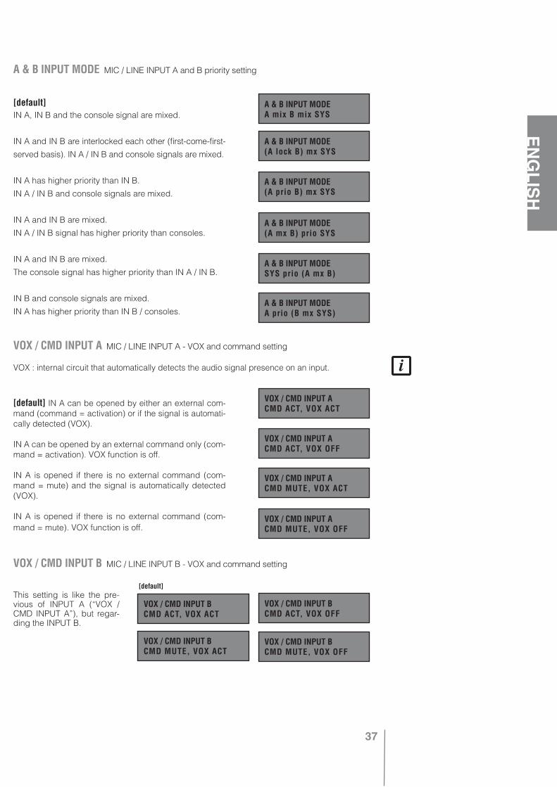
37
ENGLISH
INTERPRETATION Interpretation mode setting (sequential / simultaneous / off)
[default] IN A, IN B and the console signal are mixed.
IN A and IN B are interlocked each other (first-come-first-
served basis). IN A / IN B and console signals are mixed.
IN A has higher priority than IN B.
IN A / IN B and console signals are mixed.
IN A and IN B are mixed.
IN A / IN B signal has higher priority than consoles.
IN A and IN B are mixed.
The console signal has higher priority than IN A / IN B.
IN B and console signals are mixed.
IN A has higher priority than IN B / consoles.
VOX : internal circuit that automatically detects the audio signal presence on an input.
[default] IN A can be opened by either an external com-mand (command = activation) or if the signal is automati-cally detected (VOX).
IN A can be opened by an external command only (com-mand = activation). VOX function is off.
IN A is opened if there is no external command (com-mand = mute) and the signal is automatically detected (VOX).
IN A is opened if there is no external command (com-mand = mute). VOX function is off.
This setting is like the pre-vious of INPUT A (“VOX / CMD INPUT A”), but regar-ding the INPUT B.
A & B INPUT MODE MIC / LINE INPUT A and B priority setting
A & B INPUT MODEA mix B mix SYS
A & B INPUT MODE(A lock B) mx SYS
A & B INPUT MODE(A prio B) mx SYS
A & B INPUT MODE(A mx B) prio SYS
A & B INPUT MODESYS prio (A mx B)
VOX / CMD INPUT A MIC / LINE INPUT A - VOX and command setting
VOX / CMD INPUT ACMD ACT, VOX ACT
VOX / CMD INPUT ACMD ACT, VOX OFF
VOX / CMD INPUT ACMD MUTE, VOX ACT
VOX / CMD INPUT ACMD MUTE, VOX OFF
VOX / CMD INPUT B MIC / LINE INPUT B - VOX and command setting
VOX / CMD INPUT BCMD ACT, VOX ACT
VOX / CMD INPUT BCMD ACT, VOX OFF
VOX / CMD INPUT BCMD MUTE, VOX ACT
VOX / CMD INPUT BCMD MUTE, VOX OFF
[default]
A & B INPUT MODEA prio (B mx SYS)
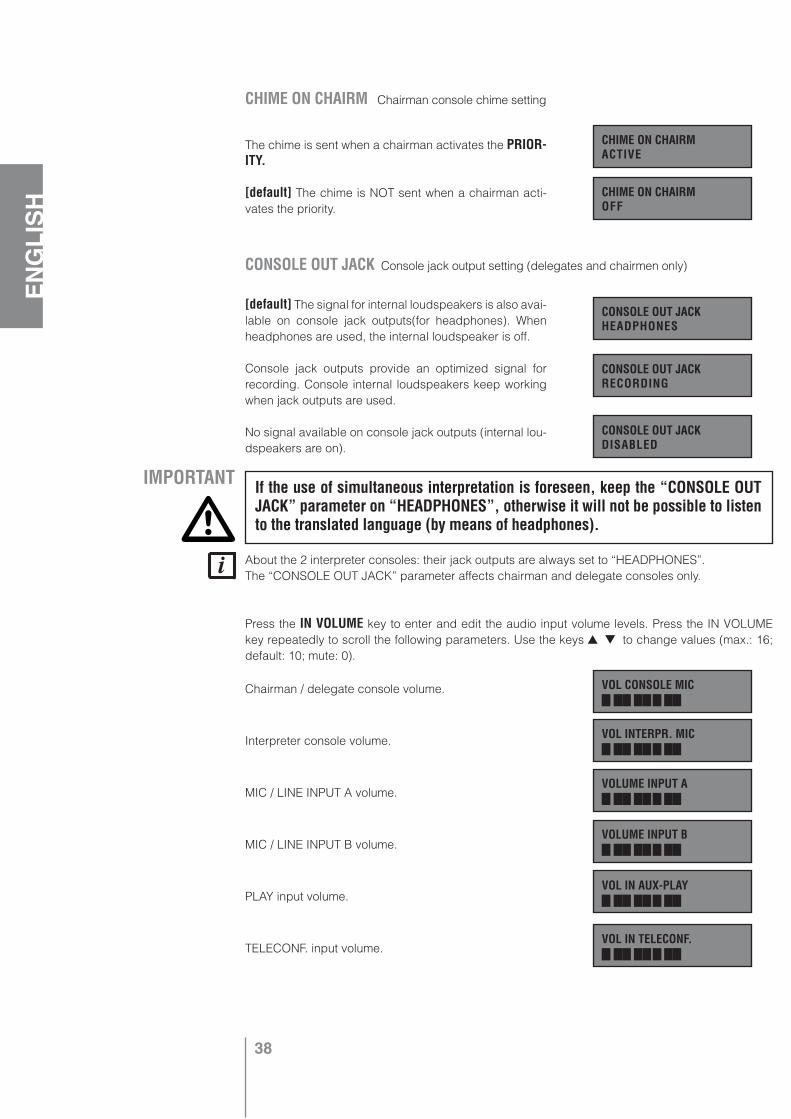
38
ENGLISH
The chime is sent when a chairman activates the PRIOR-ITY.
[default] The chime is NOT sent when a chairman acti-vates the priority.
[default] The signal for internal loudspeakers is also avai-lable on console jack outputs(for headphones). When headphones are used, the internal loudspeaker is off.
Console jack outputs provide an optimized signal for recording. Console internal loudspeakers keep working when jack outputs are used.
No signal available on console jack outputs (internal lou-dspeakers are on).
About the 2 interpreter consoles: their jack outputs are always set to “HEADPHONES”.The “CONSOLE OUT JACK” parameter affects chairman and delegate consoles only.
Press the IN VOLUME key to enter and edit the audio input volume levels. Press the IN VOLUME key repeatedly to scroll the following parameters. Use the keys to change values (max.: 16; default: 10; mute: 0).
Chairman / delegate console volume.
Interpreter console volume.
MIC / LINE INPUT A volume.
MIC / LINE INPUT B volume.
PLAY input volume.
TELECONF. input volume.
CHIME ON CHAIRMACTIVE
CHIME ON CHAIRMOFF
CONSOLE OUT JACKHEADPHONES
CONSOLE OUT JACKRECORDING
CONSOLE OUT JACKDISABLED
VOL CONSOLE MIC
VOL INTERPR. MIC
VOLUME INPUT A
VOLUME INPUT B
VOL IN AUX-PLAY
VOL IN TELECONF.
CONSOLE OUT JACK Console jack output setting (delegates and chairmen only)
CHIME ON CHAIRM Chairman console chime setting
IMPORTANT If the use of simultaneous interpretation is foreseen, keep the “CONSOLE OUT JACK” parameter on “HEADPHONES”, otherwise it will not be possible to listen to the translated language (by means of headphones).

39
ENGLISH
Press the OUT VOLUME key to enter and edit the audio OUTPUT volume levels. Press the OUT VOLUME key repeatedly to scroll the following parameters. Use the keys to change values (max.: 16; default: 10; mute: 0).
Console internal loudspeaker volume.
MAIN OUT volume.
When an error is displayed, press the ENTER key to exit.
During the system reboot:
CHRM INIT ERROR: more than 3 chairman consoles have been found.
DEL INIT ERROR: more than 30 consoles have been found in 1 line.
Note: should the delegate/chairman and interpreter lines be inverted (wrongly connected to the central unit DMU 6100), the system would not be able to notice this problem, therefore the LCD would not display any error message.
When the system is operating:
CONSOLE ERROR : a chairman / delegate console does not work any more (example: line 2, position 15).
CONSOLE ERROR : an interpreter console does not work any more (example: interpreter no.2).
The “position 1” is the first console directly connected to the DMU 6100 central unit; the “position 30” is the line last console.
Should be present more issues, the LCD would display 1 at a time only (since the system reboot).It is therefore necessary to fix the first error in order to see on the display the next (if present), after rebooting the system.
This message may appear, after turning the system on (and after the console check), when problems have oc-curred during the EEPROM (internal memory) reading. In this case, all default parameters are restored and techni-cal assistance is required (when possible).
Power supply and fuse faults (technical assistance required):
Internal 12 V power supply fault
VOL CONSOLE SPKR
VOL MAIN OUT
CONSOLE OUT JACK Console jack output setting (delegates and chairmen only)
ERROR MESSAGES
CHRM INIT ERRORPRESS SET, ENTER
DEL INIT ERRORPRESS SET, ENTER
CONSOLE ERRORLINE 2 POS.15
CONSOLE ERRORINTERPRETER 2
DEFAULT MODESERVICE REQUIRED
12V POWER FAULTSERVICE REQUIRED

40
ENGLISH
1
Internal 24 V power supply fault
External 24 V power supply fault (DPS 6202)
Console line 1 and 2 fuse fault
Console line 3 and 4 fuse fault (DEC 6104)
Console line 5 and 6 fuse fault (DEC 6104)
TOP VIEW
1 Microphone with red light-ring.2 Internal loudspeaker.3 LED Colours: red, green, yellow (red and
green). It depends on the console setting (chairman, delegate, interpreter).
4 2 buttons (1 short and 1 long) with different functions depending on the console setting (chairman, delegate, interpreter).
5 2 small buttons to adjust the internal loud-speaker volume.
LATERAL PANELS
There are 2 (1 on the left side, 1 on the right side) 3.5 mm - 1/8” jack outputs for headphones / recording.
REAR PANEL
1 IN 10 pole RJ input connector for the (10 pole) special cable coming from the previous con-sole (or from the central unit DMU 6100).
2 OUT 10 pole RJ output connector for the (10 pole) special cable connected to the next console.
3 DIP switches to set the console (chairman, delegate or interpreter).
4 Line termination switch (it must be pushed in the last console of a line).
24 V POWER FAULTSERVICE REQUIRED
DMS 6410 MICROPHONE CONSOLE
EXT 24 V PWR FLTSERVICE REQUIRED
L1&L2 FUSE FAULTSERVICE REQUIRED
L3&L4 FUSE FAULTSERVICE REQUIRED
L5&L6 FUSE FAULTSERVICE REQUIRED
4
3 2
5
4 3 2 1
Delegate console
Chairman console
Interpreter console
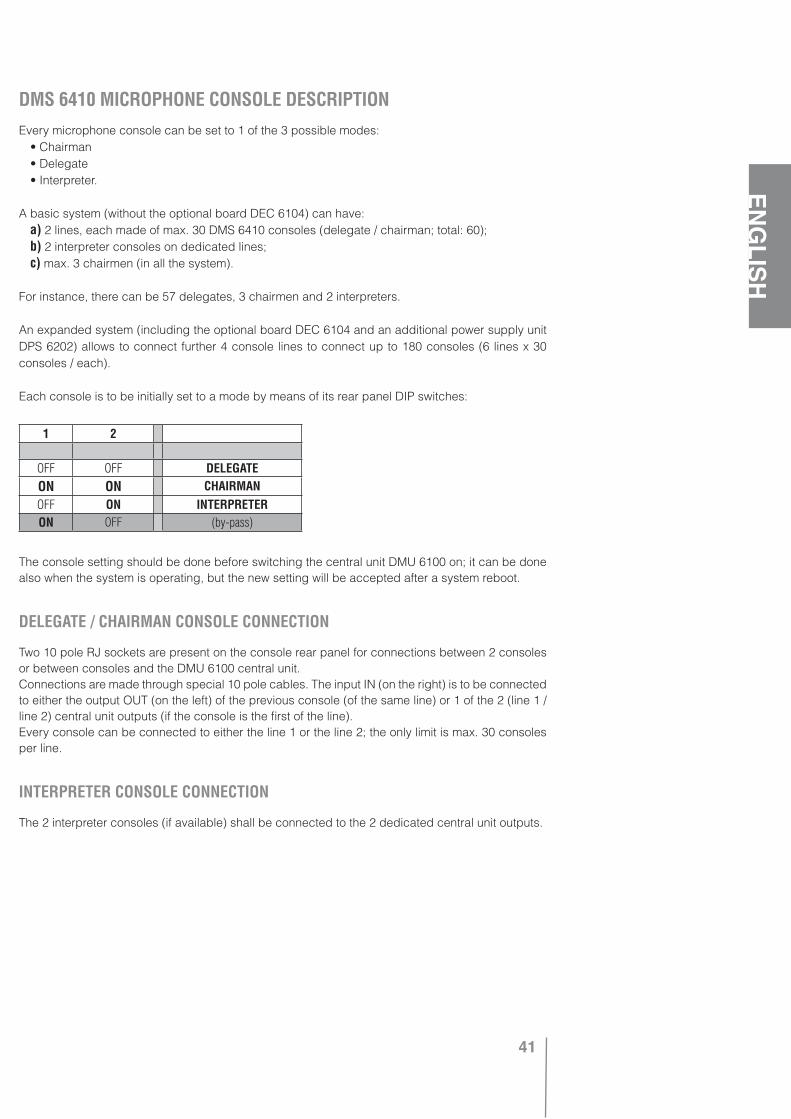
41
ENGLISH
DMS 6410 MICROPHONE CONSOLE DESCRIPTIONEvery microphone console can be set to 1 of the 3 possible modes: • Chairman • Delegate • Interpreter.
A basic system (without the optional board DEC 6104) can have: a) 2 lines, each made of max. 30 DMS 6410 consoles (delegate / chairman; total: 60); b) 2 interpreter consoles on dedicated lines; c) max. 3 chairmen (in all the system).
For instance, there can be 57 delegates, 3 chairmen and 2 interpreters.
An expanded system (including the optional board DEC 6104 and an additional power supply unit DPS 6202) allows to connect further 4 console lines to connect up to 180 consoles (6 lines x 30 consoles / each).
Each console is to be initially set to a mode by means of its rear panel DIP switches:
The console setting should be done before switching the central unit DMU 6100 on; it can be done also when the system is operating, but the new setting will be accepted after a system reboot.
DELEGATE / CHAIRMAN CONSOLE CONNECTION
Two 10 pole RJ sockets are present on the console rear panel for connections between 2 consoles or between consoles and the DMU 6100 central unit.Connections are made through special 10 pole cables. The input IN (on the right) is to be connected to either the output OUT (on the left) of the previous console (of the same line) or 1 of the 2 (line 1 / line 2) central unit outputs (if the console is the first of the line).Every console can be connected to either the line 1 or the line 2; the only limit is max. 30 consoles per line.
INTERPRETER CONSOLE CONNECTION
The 2 interpreter consoles (if available) shall be connected to the 2 dedicated central unit outputs.
1 2
OFF OFF DELEGATEON ON CHAIRMANOFF ON INTERPRETERON OFF (by-pass)

42
ENGLISH
LINE TERMINATION
Each console line is to be terminated at its end:
• About delegate / chairman consoles: only the line last console LINE TERMINATION switch shall be pushed (set to ON; this switch is on the console rear panel). On the other consoles, the LINE TERMINATION switch shall be set to OFF. Should a console (that is not the last of the line) have the LINE TERMINATION switch wrongly set to ON, during the system reboot all previous consoles would be recognized properly (their light-rings are lit), while the following consoles would not be found by the DMU 6100 central unit.
• When an interpreter console is connected, make sure that the relevant INTERPRETER LINE TER-MINATION DIP switch of the DMU 6100 central unit is set to OFF (interpreter console: available).Note: the interpreter console LINE TERMINATION switch has no effect.
• If an interpreter console is not connected to dedicated central unit port, it will be necessary to set the relevant INTERPRETER LINE TERMINATION DIP switch (of the DMU 6100 central unit) to ON.
JACK OUTPUTS
On DMS 6410 console lateral panels, there are 2 jack outputs (3.5 mm - 1/8”; an output on both sides). Their output signal depends on the system configuration and the console operating mode (delegate / chairman / interpreter).The jack outputs can be configured by means of the “CONSOLE OUT JACK” parameter (SET menu):
• HEADPHONES The jack output audio signal is optimized for headphones. If headphones are used, the console internal loudspeaker turns off and the volume can be adjusted by using the relevant 2 small buttons from 0 to the maximum value set on the DMU 6100 central unit.
• RECORDING The jack output audio signal is optimized for recording (the console internal loud-speaker does not turn off when a jack output is used). The volume control is enabled and the level can be adjusted between (about) 30% and 100%, but it cannot be set to 0. The DMU 6100 central unit volume setting has no effect.
• DISABLED All jack outputs (but interpreter consoles) are disabled. Console internal loudspeakers are anyway activated.
About the 2 interpreter consoles: their jack outputs are always set to the HEADPHONES mode; the volume is always adjustable from 0 to the maximum value set on the DMU 6100 central unit.The “CONSOLE OUT JACK” parameter (of the central unit) affects chairman and delegate consoles only.
TOP PANELThere are 2 volume buttons, 2 selection buttons and a bi-colour LED, of which function depends on the console operating mode (delegate, chairman, interpreter) and the system configuration.
INTERNAL LOUDSPEAKERThe volume buttons allow to adjust the volume from 0 to the maximum value set on the DMU 6100 central unit. The internal loudspeaker is always off when: the simultaneous translation is in progress, the console microphone is open, headphones are connected to at least 1 jack output in “HEADPHO-NES” mode.
IMPORTANT If the use of simultaneous interpretation is foreseen, keep the “CONSOLE OUT JACK” parameter on “HEADPHONES”, otherwise it will not be possible to listen to the translated language (by means of headphones).
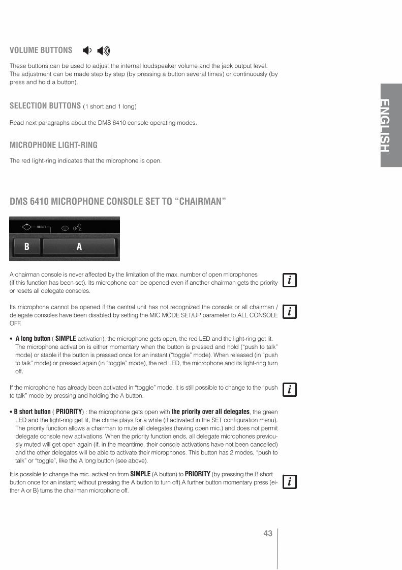
43
ENGLISH
VOLUME BUTTONS
These buttons can be used to adjust the internal loudspeaker volume and the jack output level.The adjustment can be made step by step (by pressing a button several times) or continuously (by press and hold a button).
SELECTION BUTTONS (1 short and 1 long)
Read next paragraphs about the DMS 6410 console operating modes.
MICROPHONE LIGHT-RING
The red light-ring indicates that the microphone is open.
A chairman console is never affected by the limitation of the max. number of open microphones(if this function has been set). Its microphone can be opened even if another chairman gets the priority or resets all delegate consoles.
Its microphone cannot be opened if the central unit has not recognized the console or all chairman / delegate consoles have been disabled by setting the MIC MODE SET/UP parameter to ALL CONSOLE OFF.
• A long button ( SIMPLE activation): the microphone gets open, the red LED and the light-ring get lit. The microphone activation is either momentary when the button is pressed and hold (“push to talk”
mode) or stable if the button is pressed once for an instant (“toggle” mode). When released (in “push to talk” mode) or pressed again (in “toggle” mode), the red LED, the microphone and its light-ring turn off.
If the microphone has already been activated in “toggle” mode, it is still possible to change to the “push to talk” mode by pressing and holding the A button.
• B short button ( PRIORITY) : the microphone gets open with the priority over all delegates, the green LED and the light-ring get lit, the chime plays for a while (if activated in the SET configuration menu). The priority function allows a chairman to mute all delegates (having open mic.) and does not permit delegate console new activations. When the priority function ends, all delegate microphones previou-sly muted will get open again (if, in the meantime, their console activations have not been cancelled) and the other delegates will be able to activate their microphones. This button has 2 modes, “push to talk” or “toggle”, like the A long button (see above).
It is possible to change the mic. activation from SIMPLE (A button) to PRIORITY (by pressing the B shortbutton once for an instant; without pressing the A button to turn off).A further button momentary press (ei-ther A or B) turns the chairman microphone off.
DMS 6410 MICROPHONE CONSOLE SET TO “CHAIRMAN”
AB
44
ENGLISH
• If both buttons are pressed together at the same time (A + B ), a chairman will get the PRIORITY and all delegate console will be immediately forced off ( RESET) . This event is signaled by the green LED (first flashing for 3 seconds, then lit).
It is possible to RESET, when in SIMPLE activation or with PRIORITY, without turning the console off.A further button momentary press (either A or B) turns the chairman microphone off.
When the PRIORITY function (or RESET) is in progress, the PRIORITY cannot be got by anotherchairman.
When the RESET function is in progress, it cannot be activated by another chairman (while the RE-SET is always possible during a SIMPLE / PRIORITY activation of the other 2 chairmen).
• The flashing yellow (red + green) LED (on chairman consoles with open microphone only): • During the simultaneous translation, it indicates the interpreter request “SPEAK SLOWLY”. • During the sequential translation, it indicates the interpreter console activation (therefore, the
chairman microphone is momentary muted).
POSSIBLE SELECTION SEQUENCES
A A button press. - B B button press.
OFF > A > SIMPLE > A > OFF
OFF > B > PRIORITY > A or B > OFF
OFF > A > SIMPLE > B > PRIORITY > A or B > OFF
OFF > A + B > RESET > A or B > OFF
OFF > A > SIMPLE > A + B > RESET > A or B > OFF
OFF > B > PRIORITY > A + B > RESET > A or B > OFF
OFF > A > SIMPLE > B > PRIORITY > A + B > RESET A or B > OFF
LED codes
RED: the chairman microphone is open (its light-ring is lit) in SIMPLE mode.
FLASHING GREEN FOR 3 SECONDS ONLY: the chairman has just activated the RESET function.
GREEN: the chairman has got the PRIORITY (or after a RESET).
FLASHING YELLOW: the interpreter has requested to SPEAK SLOWLY during the simultaneous tran-slation or it simply indicates the interpreter console activation during the sequential translation (the-refore, the chairman microphone is momentary muted).
Both LED and light-ring are flashing: data transmission from / to the central unit has failed for 30 seconds (or longer). Should this happen, the console would keep on operating until the chairman turns it off (and then it would not be possible to turn it on again as long as the technical problem is still present).

45
ENGLISH
Every delegate is affected by the limitation of the max. number of open microphones (from 1 to 6, if this function has been set in the MIC MODE SET/UP parameter of the MODE menu).If this limit is reached, it will not be possible to activate a further delegate console.If the MIC MODE SET/UP parameter is set to “1 MIC ACT+O/RIDE”, only 1 microphone will be open at a time and also overridden by the next delegate who turns its console on.
The console cannot be activated (and its microphone cannot be open) if: • A chairman is resetting all consoles (RESET). • A chairman has got the PRIORITY. • The central unit has not recognized that console. • All delegate consoles have been disabled (by setting the central unit MIC MODE SET/UP para-
meter).
• A long button: the microphone gets open, the red LED and the light-ring get lit. The microphone activation is either momentary when the button is pressed and hold (“push to
talk” mode) or stable if the button is pressed once for an instant (“toggle” mode). When released (in “push to talk” mode) or pressed again (in “toggle” mode), the red LED, the microphone and its light-ring turn off. If the max. number of open microphones is reached, any attempt to turn the console on will cause:
a) If there is no booking (RESERVATION NEXT parameter: OFF), the red LED will flash for 3 secon ds.b) If the booking is accepted (up to 10 delegates; RESERVATION NEXT parameter: NEXT + n;
NEXT), the green LED will lit (note: another button press will cancel the booking). The red LED flashes for 3 seconds also when the max. number of bookings has already been
reached.
If the microphone has already been activated in “toggle” mode, it is still possible to change to the “push to talk” mode by pressing and holding the A button.
• B short button (MUTE): it momentary mutes the microphone (if this has been previously opened by using the A long button in “toggle” mode) and the red LED starts flashing. Another press cancels the MUTE state, the microphone is open and the red LED is lit (without flashing) again.
During its MUTE state, the delegate console is anyway counted and added to the sum of all openmicrophones (that is significant only if the max. number of open microphone limitation has been set).
The delegate console can be turned off by pressing the A long button also when the microphone is muted.
When a chairman gets the PRIORITY, all (activated) delegate consoles will be momentary muted and their red LEDs will start flashing). When the PRIORITY state ends, all microphones of (previou-sly) activated delegate consoles will be on again.
When a chairman uses the RESET function, all (activated or booked) delegate consoles will be forced off.
DMS 6410 MICROPHONE CONSOLE SET TO “DELEGATE”
AB
46
ENGLISH
• The flashing yellow (red + green) LED: • During the simultaneous translation, it indicates the interpreter request “SPEAK SLOWLY”. • During the sequential translation, it indicates the interpreter console activation (therefore, the
delegate microphone is momentary muted).The flashing yellow LED can appear on delegate consoles with either open or muted microphones
(MUTE), while it does not appear on consoles that are disabled or booked (green LED lit).
MIC AUTO-OFF FUNCTION (DELEGATES ONLY)
If the MIC AUTO-OFF function is enabled (in the central unit software), after 30 seconds (with openmicrophone) of continuous no voice detection, the relevant console will be automatically turned off.Every time that a delegate restart speaking during the last 5 available seconds, a 10 second extra time will be granted (before turning its microphone off).
When a delegate microphone is momentary muted (MUTE by either a chairman or the delegate interpreter console during the sequential translation), the MIC AUTO-OFF function is suspended.
LED CODES
FLASHING RED FOR 3 SECONDS ONLY: failed try to activate the console (its light-ring does not get lit). The microphone is still off and even the booking request is not accepted, because the max. number of open microphones has already been reached (and the booking is not available too) or a chairman has got the PRIORITY (or used the RESET command).
GREEN: failed try to activate the console (its light-ring does not get lit), because it has already been reached the max. number of open microphones, yet the green LED indicates that the booking has been accepted.
RED: the delegate microphone is open (and its light-ring is lit).
FLASHING RED: the delegate console is activated, but the microphone is momentary muted (MUTE function). Possible reasons: the B short button has been pressed (MUTE) or a chairman has got the PRIORITY; in the latter case, the delegate cannot speak, but just turns its console off or waits for the PRIORITY end.
FLASHING YELLOW: the interpreter has requested to SPEAK SLOWLY during the simultaneous tran-slation or it simply indicates the interpreter console activation during the sequential translation (the-refore, the delegate microphone is momentary muted).
LED and the light-ring gets off without pressing any button: the MIC AUTO-OFF function has automa-tically turned the console off after a certain time or a chairman has used the RESET command.Both LED and light-ring are flashing: data transmission from / to the central unit has failed for 30 seconds (or longer). Should this happen, the console would be forced off (and then it would not be possible to turn it on again as long as the technical problem is still present).
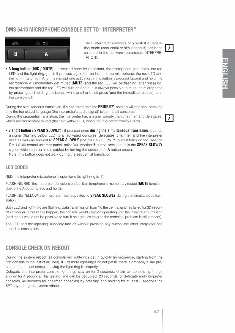
47
ENGLISH
The 2 interpreter consoles only work if a transla-tion mode (sequential or simultaneous) has been selected in the software (parameter: INTERPRE-TATION).
• A long button (MIC / MUTE) : if pressed once for an instant, the microphone gets open, the red LED and the light-ring get lit; if pressed again (for an instant), the microphone, the red LED and the light-ring turn off. After the microphone activation, if this button is pressed (again) and hold, the microphone will momentary get muted (MUTE) and the red LED will be flashing; after releasing, the microphone and the red LED will turn on again. It is always possible to mute the microphone by pressing and holding this button, while another quick press (and the immediate release) turns the console off.
During the simultaneous translation, if a chairman gets the PRIORITY, nothing will happen, because only the translated language (the interpreter’s audio signal) is sent to all consoles.During the sequential translation, the interpreter has a higher priority than chairmen and delegates, which are momentary muted (flashing yellow LED) when the interpreter console is on.
• B short button ( SPEAK SLOWLY) : if pressed once during the simultaneous translation, it sends a signal (flashing yellow LED) to all activated consoles (delegates, chairmen and the interpreter itself as well) as request to SPEAK SLOWLY (the “SPEAK SLOWLY” output turns on too; see the DMU 6100 central unit rear panel, point 34). Another B button press cancels the SPEAK SLOWLY signal, which can be also disabled by turning the console off (A button press).
Note: this button does not work during the sequential translation.
LED CODES
RED: the interpreter microphone is open (and its light-ring is lit).
FLASHING RED: the interpreter console is on, but its microphone is momentary muted (MUTE function, due to the A button press and hold).
FLASHING YELLOW: the interpreter has requested to SPEAK SLOWLY during the simultaneous tran-slation.
Both LED and light-ring are flashing: data transmission from / to the central unit has failed for 30 secon-ds (or longer). Should this happen, the console would keep on operating until the interpreter turns it off (and then it would not be possible to turn it on again as long as the technical problem is still present).
The LED and the light-ring suddenly turn off without pressing any button: the other interpreter has turned its console on.
During the system reboot, all console red light-rings get lit quickly (in sequence, starting from the first console to the last of all lines). If 1 or more light-rings do not get lit, there is probably a line pro-blem after the last console having the light-ring lit properly.Delegate and interpreter console light-rings stay on for 2 seconds; chairman console light-rings stay on for 4 seconds. This testing time can be decupled (20 seconds for delegate and interpreter consoles, 40 seconds for chairman consoles) by pressing and holding for at least 3 seconds the SET key during the system reboot.
DMS 6410 MICROPHONE CONSOLE SET TO “INTERPRETER”
CONSOLE CHECK ON REBOOT
AB
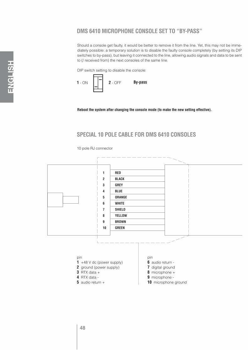
48
ENGLISH
Should a console get faulty, it would be better to remove it from the line. Yet, this may not be imme-diately possible: a temporary solution is to disable the faulty console completely (by setting its DIP switches to by-pass), but leaving it connected to the line, allowing audio signals and data to be sent to (/ received from) the next consoles of the same line.
DIP switch setting to disable the console:
Reboot the system after changing the console mode (to make the new setting effective).
DMS 6410 MICROPHONE CONSOLE SET TO “BY-PASS”
By-pass
SPECIAL 10 POLE CABLE FOR DMS 6410 CONSOLES
1 RED
2 BLACK
3 GREY
4 BLUE
5 ORANGE
6 WHITE
7 SHIELD
8 YELLOW
9 BROWN
10 GREEN
10 pole RJ connector
pin1 +48 V dc (power supply)2 ground (power supply) 3 RTX data + 4 RTX data - 5 audio return +
pin6 audio return -7 digital ground8 microphone +9 microphone -10 microphone ground
1 - ON 2 - OFF
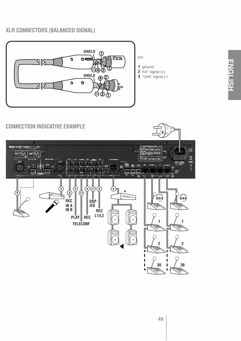
49
ENGLISH
XLR CONNECTORS (BALANCED SIGNAL)DMS 6410 MICROPHONE CONSOLE SET TO “BY-PASS”
SPECIAL 10 POLE CABLE FOR DMS 6410 CONSOLES
pin
1 ground2 hot” signal (+) 3 “cold” signal (-)
CONNECTION INDICATIVE EXAMPLE
»
»»
»
»
»
»
»
»
»
RECIN AIN B
»
PLAY
TELECONF
REC
DSP/EQ
RECL1/L2
1 1
2 2
30 30
SHIELD
SHIELD
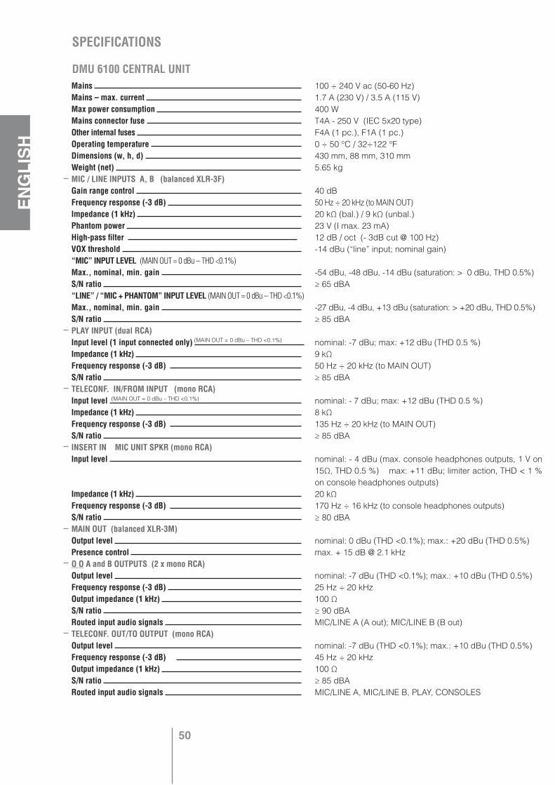
50
ENGLISH
Mains Mains – max. current Max power consumption Mains connector fuse Other internal fuses Operating temperature Dimensions (w, h, d) Weight (net) MIC / LINE INPUTS A, B (balanced XLR-3F) Gain range control Frequency response (-3 dB) Impedance (1 kHz) Phantom power High-pass filter VOX threshold “MIC” INPUT LEVEL (MAIN OUT = 0 dBu – THD <0.1%)Max., nominal, min. gain S/N ratio “LINE” / “MIC + PHANTOM” INPUT LEVEL (MAIN OUT = 0 dBu – THD <0.1%) Max., nominal, min. gain S/N ratio PLAY INPUT (dual RCA)Input level (1 input connected only) Impedance (1 kHz) Frequency response (-3 dB) S/N ratio TELECONF. IN/FROM INPUT (mono RCA)Input level Impedance (1 kHz) Frequency response (-3 dB) S/N ratio INSERT IN MIC UNIT SPKR (mono RCA)Input level
Impedance (1 kHz) Frequency response (-3 dB) S/N ratio MAIN OUT (balanced XLR-3M)Output level Presence control O O A and B OUTPUTS (2 x mono RCA)Output level Frequency response (-3 dB) Output impedance (1 kHz) S/N ratio Routed input audio signals TELECONF. OUT/TO OUTPUT (mono RCA)Output level Frequency response (-3 dB) Output impedance (1 kHz) S/N ratio Routed input audio signals
100 ÷ 240 V ac (50-60 Hz)1.7 A (230 V) / 3.5 A (115 V)400 WT4A - 250 V (IEC 5x20 type)F4A (1 pc.), F1A (1 pc.)0 ÷ 50 °C / 32÷122 °F430 mm, 88 mm, 310 mm5.65 kg
40 dB50 Hz ÷ 20 kHz (to MAIN OUT)20 kΩ (bal.) / 9 kΩ (unbal.)23 V (I max. 23 mA)12 dB / oct (- 3dB cut @ 100 Hz)-14 dBu (“line” input; nominal gain)
-54 dBu, -48 dBu, -14 dBu (saturation: > 0 dBu, THD 0.5%)≥ 65 dBA
-27 dBu, -4 dBu, +13 dBu (saturation: > +20 dBu, THD 0.5%)≥ 85 dBA
nominal: -7 dBu; max: +12 dBu (THD 0.5 %)9 kΩ50 Hz ÷ 20 kHz (to MAIN OUT)≥ 85 dBA
nominal: - 7 dBu; max: +12 dBu (THD 0.5 %)8 kΩ135 Hz ÷ 20 kHz (to MAIN OUT)≥ 85 dBA
nominal: - 4 dBu (max. console headphones outputs, 1 V on 15Ω, THD 0.5 %) max: +11 dBu; limiter action, THD < 1 % on console headphones outputs)20 kΩ170 Hz ÷ 16 kHz (to console headphones outputs)≥ 80 dBA
nominal: 0 dBu (THD <0.1%); max.: +20 dBu (THD 0.5%)max. + 15 dB @ 2.1 kHz
nominal: -7 dBu (THD <0.1%); max.: +10 dBu (THD 0.5%)25 Hz ÷ 20 kHz100 Ω≥ 90 dBAMIC/LINE A (A out); MIC/LINE B (B out)
nominal: -7 dBu (THD <0.1%); max.: +10 dBu (THD 0.5%)45 Hz ÷ 20 kHz100 Ω≥ 85 dBAMIC/LINE A, MIC/LINE B, PLAY, CONSOLES
SPECIFICATIONS
DMU 6100 CENTRAL UNIT
(MAIN OUT = 0 dBu – THD <0.1%)
(MAIN OUT = 0 dBu – THD <0.1%)

51
ENGLISH
DMS 6410 MICROPHONE CONSOLE
O O SYSTEM OUTPUT (dual RCA)Output level Frequency response (-3 dB) Output impedance (1 kHz) S/N ratio Routed input audio signals O O LINE 1 and LINE 2 OUTPUTS (2 x mono RCA)Output level Frequency response (-3 dB) Output impedance (1 kHz) S/N ratio Routed input audio signals INSERT OUT MIC UNIT SPKR (mono RCA)Output level Frequency response (-3 dB) Output impedance (1 kHz) S/N ratio Routed input audio signals MONITOR AMPLIFIER (internal)Power Headphones (6.3 mm jack on front panel) Frequency response (-3 dB) S/N ratio Routed input audio signals 2 POLE I/O EURO CONNECTORSINPUTS: MIC/LINE INPUT A CMD IN, MIC/LINE INPUT B CMD IN, CHIME COMMANDActivation Max. voltage; max. current INPUT: REMOTE VOLUME CONTROLPotentiometer to be used as remote ctrl. Max. voltage; max. current OUTPUT: “SPEAK SLOWLY” (dry closing contact)Max. voltage; max. current RJ CONNECTORSLINE 1, LINE 2, INPREPRETER I, INTERPRETER IIMax. voltage; max current
Microphone type Frequency response (-3 dB) S/N ratio (to MAIN OUT) Internal limiter MIC AUTO-OFF signal threshold Voltage; current
Internal amplifier power Dimensions (base only; w, h, d) Weight Gooseneck mic. length Included connection cable JACK OUTPUTS Max. power (headphones mode) Output level (recording mode) Frequency response (-3 dB)
nominal: -7 dBu (THD <0.1%); max.: +10 dBu (THD 0.5%)35 Hz ÷ 20 kHz100 Ω≥ 85 dBAMIC/LINE A, MIC/LINE B, TELECONF. IN/FROM, CONSOLES
nominal: 0 dBu; max.: +10 dBu (console limiter threshold)100 Hz ÷ 15 kHz100 Ω≥ 60 dBA (1 activated console only)All DELEGATE and CHAIRMAN CONSOLES of each line.
nominal: -7 dBu; max.: +10 dBu (THD 0.5%)25 Hz ÷ 25 kHz100 Ω≥ 85 dBAALL (either INTERPRETER CONSOLES or ALL the OTHER INPUTS)
1 W (on a 4 Ω loudspeaker) – THD 1%2 V RMS on 16 Ω100 Hz ÷ 15 kHz≥ 80 dBAALL (either INTERPRETER CONSOLES or ALL the OTHER INPUTS)
by shorting the 2 pins through a contact (R: < 500 Ω)48 V dc; 9 mA
20÷50 kΩ (suggested: 22 kΩ) type B5 V dc; 5 mA
28 V dc; 1 A
48 V dc; 1.5 A on each LINE with 30 consoles
electret, cardioid70 Hz ÷ 18 kHz≥ 60 dBAup to + 32dB over 100% level-20 dB48 V dc; nominal < 20 mA, max. 50 mA (internal lspk. : max. volume)1 W (THD <1%)200 mm, 135 mm, 60 mm1.09 kg465 mm10 pole special cable with RJ connectors, 2.5 m long
60 mW on 16 Ω (<0.5% THD)nominal: - 4 dBu (0.2% THD), max. + 5 dBu170 Hz ÷ 16 kHz
52
DEU
TSCH
Bevor sie dieses Produkt einschalten und benutzen, lesen Sie, die in diesem Leitfaden enthaltenen Anweisungen, aufmerksam durch. Der Leitfaden ist für künftige Informationen aufzubewahren. Der vorliegende Leitfaden stellt einen Bestandteil des Produkts dar und muss bei einem Eigentümerwechsel ebenfalls übertragen werden, damit der neue Eigentümer die Einstellungs-, Verwendungs und Sicherheitswarnhinweise kennenlernt. Die falsche Anwendung und Einstellung des Produkts befreien RCF S.p.A von jeglicher Verantwortung.
Achtung: Um Stromstöße oder Feuer zu vermeiden, darf dieses Produkt nie Feuchtigkeit oder Regen ausgesetzt werden.1. Sicherheitshinweise: Alle Hinweise, vor allem jene, die die Sicherheit betreffen, müssen mit besonderer Sorgfalt gelesen werden, denn sie können wichtige Informationen enthalten.
2.1 Direkte Stromversorgung aus dem Netza. Die Elektrizitätsspannung des Geräts kann einen so hohen Wert/Grad annehmen, dass
es Menschen einen Stromschlag versetzt: Schließen Sie demnach das Gerät nie bei eingeschalteter Netzversorgung an.
b. Bevor Sie dieses Gerät mit Energie versorgen, sichern Sie ab, dass alle Stecker richtig angeschlossen sind und dass die Spannung ihres Stromnetzes mit der ausgewiesenen Spannung des Apparats übereinstimmt. Falls dem nicht sein sollte, wenden Sie sich an den RCF Verkäufer.
c. Die Metallteile des Geräts sind mit der Erde über ein Stromkabel verbunden. Für den Fall, dass die Steckdose die Verbindung zur Erde nicht gewährleistet, wenden Sie sich an einen ausgebildeten Elektriker, der das Gerät an die Erde mit einer dafür vorgesehenen Klemme verbindet.
d. Sichern Sie sich ab, dass das Stromkabel nicht mit Füßen getreten oder von Gegenständen zerquetscht werden kann, damit ein perfekter Zustand gesichert werden kann.
e. Um einen Elektroschock zu vermeiden, öffnen Sie das Gerät niemals, im Innern gibt es keine Gegenstände, die vom Nutzer anderweitig verwendet werden könnten.
2.2 Stromversorgung über externen Versorgera. Das Gerät darf nur mit Strom aus dem hierfür vorgesehenen Versorger betrieben werden.
Stellen Sie sicher, dass die Spannung Ihres Netzes mit der Kennzeichnung auf Ihrem Gerät übereinstimmt und das der Grad und die Art (stetig oder sich ändernd) der Austrittsspannung mit der Eintrittsspannung des Geräts übereinstimmt.
Sollte dies nicht der Fall sein, wenden Sie sich an Ihren RCF Einzelhändler; vergewissern Sie sich darüber hinaus, dass die Stromversorgung nicht durch Aufprall oder Überlastung beschädigt ist.
b. Die Spannung des Stromnetzes an den der Stromversorger verbunden ist, hat einen so hohen Wert, dass ein Stromschlagrisiko für Menschen besteht. Achten Sie während der Einschaltung ans Netz (z.B. dass ihre Hände nicht nass sind) und öffnen Sie nie den Stromversorger.
c. Vergewissern Sie sich, dass das Stromkabel nicht zerquetscht ist oder durch andere Geräte zerquetscht werden kann (achten Sie besonders auf den Teil des Stromkabels nahe beim Netzstecker und auf die Stelle, wo dieser aus dem Stromversorger herausragt)
2.3 Informationen über die Batterien- Benutzen Sie immer wiederaufladbahre Batterien des in der Bedienungsanleitung angegebe-
nen Typs.- Überprüfen Sie, dass die Polarität eingehalten wird.- Lassen Sie nicht zu, dass es zu einem Kurzschluss der Batterien kommt (z.B. durch Verknüp-
fung der beiden gegensätzlichen Pole durch ein Stück Metall)- Beseitigen Sie die Batterien in den dafür vorgesehenen Behältern, durch Einhaltung der ein-
schlägigen ökologischen gesetzlichen Normen (im jeweiligen Land der Nutzung)3. Verhindern Sie, dass Gegenstände oder Flüssigkeiten ins Innere des Geräts eindringen, denn diese können einen Stromschlag auslösen.4. Nehmen Sie am Gerät keine Eingriffe/Änderungen/Reparaturen vor, außer jeneauf die ausdrücklich im Leitfaden hingewiesen wird. Wenden Sie sich an autorisierte Hilfsstellen oder an ausgebildetes Personal, wenn:
Wichtig

53
DEU
TSCH
- das Gerät nicht funktioniert (oder ungewöhnlich funktioniert)- das Stromkabel an schweren Schäden leidet- Gegenstände oder Flüssigkeiten ins Gerät eingedrungen sind- Das Gerät schweren Stößen ausgesetzt war
5. Falls dieses Gerät nicht lange genutzt wird, entfernen Sie die Spannung des Stromkabels (oder trennen Sie die externe Stromversorgung)
6. Falls aus dem Produkt ungewöhnlicher Geruch oder Qualm austritt, schalten Sie das Gerät und den Strom sofort aus (oder trennen Sie die externe Stromversorgung)
7. Schalten Sie an dieses Produkt keine nicht dafür vorgesehenen Geräte und Zubehör an. Wenn eine Installation in der Schwebe vorgesehen ist, verwenden Sie nur die dafür vorgesehenen Verankerungsstellen und versuchen Sie nicht dieses Produkt durch ungeeignete Elemente aufzuhängen. Darüber hinaus stellen Sie fest, ob die Fassung (Wände, Decke, Struktur etc. and die das Gerät verankert ist), sowie die übrigen Fixierungskomponenten (nicht von RCF gelieferte Dübel, Schrauben und Bügel) geeignet sind, die Sicherheit der Anlage während der gesamten Nutzungsdauer zu gewährleisten. Denken sie hierbei an mechanische Vibrationen, die normalerweise durch einen Wandler verursacht werden würden.Um die Gefahr eines Sturzes zu vermeiden, ist es ratsam das Gerät nicht mit andern Bauteilen zu überlasten, es sei denn auf diese Möglichkeit wird ausdrücklich im Leitfaden hingewiesen.
8. RCF S.p.A. weist ausdrücklich darauf hin, dass die Aufstellung dieses Geräts nur durch professionelle, hierfür ausgebildete Installateure (oder spezialisierte Firmen) erfolgen darf, damit die Aufstellung korrekt und nach den hierfür vorgesehenen Regelungen verläuft.Das ganze Audiosystem muss mit den Normen und den herrschenden gesetzlichen Regelungen konform sein, die das elektrische System betreffen.
9. Befestigung und FörderwagenFalls vorgesehen, wird das Produkt durch Förderwagen oder Befestigungen genutzt, die vom Hersteller empfohlen sind. Die Zusammensetzung Gerät-Halterung muss mit größter Sorgfalt bewegt werden. Unvorhergesehenes Stoppen, exzessive Schübe und unregelmäßige oder geneigte Flächen können einen Sturz des Gebildes bewirken.
10. Es gibt unzählige mechanische und elektrische Faktoren zu beachten, wenn ein professionelles Audiosystem installiert wird (außer den aktustischen, wie der Schalldruck, die Abdeckungswinkel, der Übertragungsbereich.11. GehörverlustIst man einer zu hohen Lautstärke ausgesetzt, kann dies zu Gehörverlust führen. Das Schalldruckniveau, welches für das Gehör schädlich sein kann, variiert von Person zu Person und hängt von der Dauer ab. Um eine gefährliche Situation abzuwenden, in der man einem hohen Schalldruckniveau ausgeliefert ist, ist es notwendig, dass wer auch immer diesem Schalldruck ausgeliefert ist, die angemessenen Schutzmaßnahmen ergreift: Im Fall der Anwendung eines Wandlers um einen hohen Schalldruck zu erzeugen , ist es nötig Ohrenstöpsel oder Kopfhörer anzuziehen.
Wichtige HinweiseUm das von Kabeln induzierte Auftreten von Geräuschen zu vermeiden, die Signale von den Mikrophonen oder Anschlusssignalen übermitteln (z.B. OdB), nutzen Sie nur abgeschirmte Kabel, und vermeiden Sie es folgende Objekte in die Nähe zu stellen: • Geräte die hochintensive Magnetfelder erzeugen (z.B. Wandler mit einer hohen Leistungskraft)• Netzkabel• Anschlüsse von Lautsprechanlagen
Sicherheitshinweis• Verschließen Sie nicht die Lüftungsgitter der Einheit. Stellen Sie das Gerät nicht in die Nähe von Hitzequellen und sorgen Sie dafür, dass die Luft zirkuliert • Überlasten Sie dieses Gerät nicht allzu lang.• Überanspruchen Sie nie die Schaltungseinheiten (Tasten, Einstellknöpfe etc.)• Verwenden Sie nie Lösungsmittel, Alkohol, Benzin und andere Mittel um die externen Teile der Einheit zu reinigen.
Professionelles Audiosystem, das nur für Festinstallation vorgesehen ist.
54
DEU
TSCH
RCF bedankt sich für den Kauf dieses Produkts, welches zur Gewährung eines hohen Standards und einer hohen Zuverlässigkeit entwickelt wurde.
Beschreibung und HaupteigenschaftenDas RCF Forum 6000 System ist ein Konferenzsystem, das aus einer Zentrale, der DMU 6100 und bis zu 60 DMS 6410 Sprechstellen besteht, die an das Konferenzsystem angeschlossen sind (expandierbar bis zu 180 Sprechstellen mit optionaler Karte DEC 6104 und Netzteil DPS 6202). Die DMS 6410 Sprechstellen wird mit einem 10-poligem Spezialkabel angeschlossen. (ein 2,5 Metern Kabel gehört zum Lieferumfang).
Haupteigenschaften:
• Standardkonfiguration: bis zu 60 Sprechstellen verteilt auf die beiden Linien.
• Konfiguration mit Erweiterungskarte: bis zu 180 Sprechstellen verteilt auf sechs Linien. Die zusätzlichen 120 Sprechstellen (zur Standardkonfiguration) können an der Zentrale, durch Installation der optionalen Karte DEC 6104 und durch Hinzufügen eines externen Netzteiles DPS 6202, verbunden werden
• Zwei AUX Eingänge A und B (XLR), beide sind durch Mikroschalter konfigurierbar (PHANTOM, MIC / LINE, HIGH-PASS) und mit einer Lautstärkeregelung und einer Mute Funktion ausgestattet.
• Eingang Audio PLAY und Ausgang Audio SYSTEM für die Aufnahme.
• Ein- und Audioausgang für eine Telekonferenz.
• Simultanes oder sequentielles Übersetzungssystem (für eine übersetzte Sprache)
• Jede Sprechstelle ist als Präsident (maximal 3), Abgeordneter, Dolmetscher (maximal 2) konfigurierbar. De Präsident hat eine Prioritätsfunktion und kann alle aktiven Sprechstellen deaktivieren und evtl. Anmeldelisten löschen. Wenn 2 Dolmetschersprechstellen vorhanden sind, kann aber nur eine Sprechstelle jeweils aktiviert werden (nur ein Dolmetscherkanal).
• Hintergrundbeleuchtetes LC-Display (auf der Zentrale DMU 6100) und Funktionstasten, um das System einzustellen:
- Die Funktionsart und -weise (max. Anzahl an Delegierten oder zum Sprechen vorangemeldete Personen etc.);
- Die Konfiguration (Vorrang zwischen dem Eingang A, B und dem System, VOX Funktion Eingänge A, B; etc.)
- die Lautstärken

55
DEU
TSCH
Vorderes Paneel DMU 6100
1 Hauptschalter
2 LED „ON“ angeschaltetes Gerät
3 Signal LED des PLAY (grün) / REC (rot) Zustandes.
4 7 x Signal LED “SIGNAL / PEAK” der 6 Eingänge IN A, IN B, MIC UNITS, INTERPR. MIC, PLAY IN, TELECONF. IN und des Ausgangs MAIN OUT.
5 Umschalter PLAY / REC. Im Zustand PLAY ist der Audioausgang für die Aufnahme SYSTEM nicht aktiv; im Zustand REC,
ist der Audioeingang PLAY nicht aktiv.
6 Taste SET für die Auswahl der Parameter im Konfigurierungsmenü. Durch 3 Sekunden Drücken der Taste SET gelangt man dorthin.
7 Hintergrundbeleuchtetes LC- Display.
8 Taste IN LAUTSTÄRKE für die Lautstärkeneinstellung der Eingänge.
9 Taste OUT LAUTSTÄRKE für die Lautstärkeneinstellung der Ausgänge.
10 Taste MODE für den Zugang und die Parameterauswahl im Einstellungsmenü.
11 Tasten und : Im Anfangsmenü der Defaults (der die Ausführung visualisiert) erlaubt die-ser die Lautstärke des internen Lautsprechermonitors zu erhöhen oder zu vermindern (siehe Punkt 14); wenn hingegen ein Menü durch die Tasten SET, MODE, IN LAUTSTÄRKE und OUT LAUTSTÄRKE ausgesucht wird, wird hiermit der jeweilige Parameter eingestellt.
12 Die Taste ENTER drücken, um die Einstellungen zu bestätigen oder zu speichern. Wenn ENTER nicht gedrückt wird und man auf den anfangs Defaultbildschirm wartet, ist der Effekt je nach ausgewähltem Menü unterschiedlich:
- Keine Speicherung für das Menü SET und MODE; - für das Lautstärkenkontrollmenü sind die Parameter jedoch gespeichert. Das Drücken der Taste ENTER im Menü SET beinhaltet einen Reset des Systems mit der Folge,
dass die laufende Diskussion unterbrochen wird. Diese Prozedur (Drücken der Taste SET für 3 Sekunden, anschließend ENTER) kann auch angewandt werden, um das System warm zu starten (z.B. nachdem eine Sprechstelle hinzugefügt wurde).
13 Klinkenbuchse (6,3 mm - 1/4”) für den Kopfhörer, der Monitorlautsprecher ist deaktiviert bei eingestecktem Kopfhörer.
14 Interner Lautsprechermonitor, um das Main Out Signal abzuhören.
5
1 2 3 4
6 8 9 107
11 12 13 14
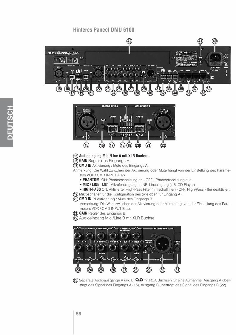
56
DEU
TSCH
Hinteres Paneel DMU 6100
15 Audioeingang Mic./Line A mit XLR Buchse .16 GAIN Regler des Eingangs A.17 CMD IN Aktivierung / Mute des Eingangs A.Anmerkung: Die Wahl zwischen der Aktivierung oder Mute hängt von der Einstellung des Parame-
ters VOX / CMD INPUT A ab. • PHANTOM ON: Phantomspeisung an - OFF: “Phantomspeisung aus. • MIC / LINE MIC: Mikrofoneingang - LINE: Lineeingang (z.B. CD-Player) • HIGH-PASS ON: Aktivierter High-Pass Filter (Trittschallfilter) - OFF: High-Pass Filter deaktiviert.19 Mikroschalter für die Konfiguration des (wie oben für Eingang A).20 CMD IN IN Aktivierung / Mute des Eingangs B. Anmerkung: Die Wahl zwischen der Aktivierung oder Mute hängt von der Einstellung des Para-
meters VOX / CMD INPUT B ab.21 GAIN Regler des Eingangs B.22 Audioeingang Mic./Line B mit XLR Buchse.
23 Separate Audioausgänge A und B mit RCA Buchsen für eine Aufnahme, Ausgang A über-trägt das Signal des Eingangs A (15), Ausgang B überträgt das Signal des Eingangs B (22).
15 1617
1819
2021
22 2324
2526
2728
2930
3132
3334
3536
3738
39
42 41 40
15 16 17 18 19 20 21 22
23 24 25 26 27 28 29 30 31
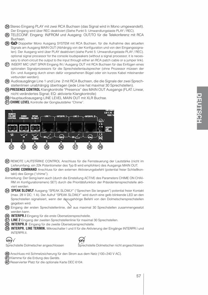
57
DEU
TSCH
24 Stereo Eingang PLAY mit zwei RCA Buchsen (das Signal wird in Mono umgewandelt). Der Eingang wird über REC deaktiviert (Siehe Punkt 5: Umwandlungstaste PLAY / REC).
25 TELECONF. Eingang: IN/FROM und Ausgang: OUT/TO für die Telekonferenz mit RCA Buchsen.
26 Doppelter Mono Ausgang SYSTEM mit RCA Buchsen, für die Aufnahme des aktuellen Signals am Ausgang MAIN OUT (Abhängig von der Konfiguration und von den Eingangssigna-len). Der Ausgang wird über PLAY deaktiviert (siehe Punkt 5: Umwandlungstaste PLAY / REC). optional signal processor for the console loudspeakers (without a signal processor, it is neces-sary to short-circuit the output to the input through either an RCA patch cable or a jumper link).
27 INSERT MIC UNIT SPKR Eingang IN / Ausgang OUT mit RCA Buchsen für das Einfügen eines optionalen Signalprozessors für die Sprechstellenlautsprecher (ohne Prozessor müssen der Ein- und Ausgang durch einen dafür vorgesehenen Bügel oder ein kurzes Kabel miteinander verbunden werden).
28 Audioausgänge Line 1 und Line 2 mit RCA Buchsen, die die Signale der zwei Sprech-stellenlinien unabhängig übertragen (jede Linie hat maximal 30 Sprechstellen).
29 PRESENCE CONTROL Klangkontrolle “Presence” des MAIN OUT Ausgangs (FLAT: Linear, nicht verändertes Signal; EQ: aktivierte Klangkontrolle)
30 Hauptaudioausgang LINE LEVEL MAIN OUT mit XLR Buchse.31 CHIME LEVEL Kontrolle der Gonglautstärke “Chime”.
32 REMOTE LAUTSTÄRKE CONTROL Anschluss für die Fernsteuerung der Lautstärke (nicht im Lieferumfang; ein 22k Potentiometer des Typ B wird empfohlen) des Ausgangs MAIN OUT.
33 CHIME COMMAND Anschluss für den externen Aktivierungsbefehl (potential freier Schließkon-takt) des Gongs (“chime”).
Anmerkung: Der Gong kann auch (durch die Einstellung ACTIVE des Parameters CHIME ON CHAI-RM im Konfigurationsmenü SET) durch die Prioritätsfunktion der Präsidentensprechstelle akti-viert werden.
34 SPEAK SLOWLY Ausgang “SPEAK SLOWLY” (“Sprechen Sie langsam”) potential freier Kontakt (max. 28 V DC; 1 A). Der Aufruf “SPEAK SLOWLY” wird durch eine gelb blinkende LED an den Sprechstellen signalisiert, wenn der dazugehörige Befehl von den Dolmetschersprechstellen gegeben wird.
35 Eingang der ersten Sprechstellenlinie, der aus maximal 30 Sprechstellen zusammengesetzt werden kann.
36 INTERPR.I Eingang für die erste Übersetzersprechstelle.37 LINE 2 Eingang der zweiten Sprechstellenlinie für maximal 30 Sprechstellen.38 INTERPR.II Eingang für die zweite Übersetzersprechstelle.39 INTERPR. LINE TERMIN. Mikroschalter I und II für die Aktivierung der Eingänge INTERPR.I und
INTERPR.II.
Sprechstelle Dolmetscher angeschlossen Sprechstelle Dolmetscher nicht angeschlossen
40 Anschluss mit Schmelzsicherung für den Strom aus dem Netz (100÷240 V AC).41 Klemme für die Erdung des Geräts.42 Reservierter Platz für die optionale Karte DEC 6104.
32 33 34 35 36 37 38 39
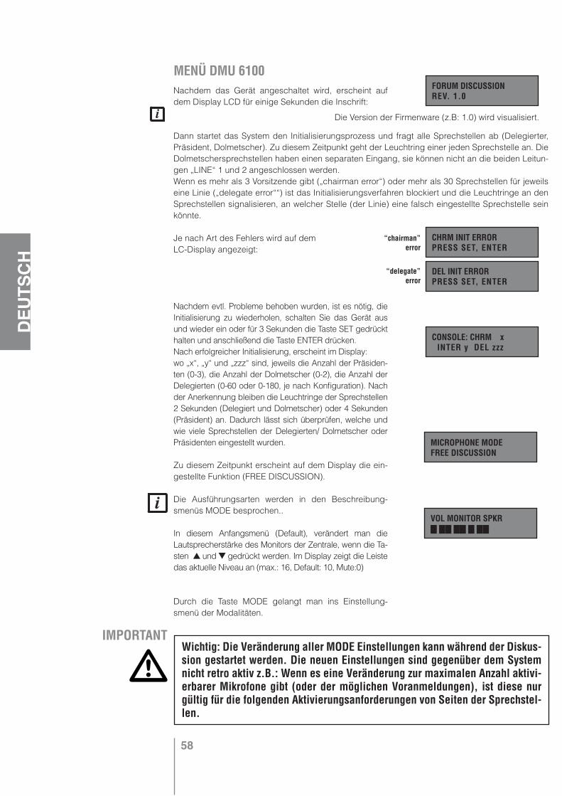
58
DEU
TSCH
MENÜ DMU 6100 Nachdem das Gerät angeschaltet wird, erscheint auf dem Display LCD für einige Sekunden die Inschrift:
Dann startet das System den Initialisierungsprozess und fragt alle Sprechstellen ab (Delegierter, Präsident, Dolmetscher). Zu diesem Zeitpunkt geht der Leuchtring einer jeden Sprechstelle an. Die Dolmetschersprechstellen haben einen separaten Eingang, sie können nicht an die beiden Leitun-gen „LINE“ 1 und 2 angeschlossen werden.Wenn es mehr als 3 Vorsitzende gibt („chairman error“) oder mehr als 30 Sprechstellen für jeweils eine Linie („delegate error““) ist das Initialisierungsverfahren blockiert und die Leuchtringe an den Sprechstellen signalisieren, an welcher Stelle (der Linie) eine falsch eingestellte Sprechstelle sein könnte.
Je nach Art des Fehlers wird auf demLC-Display angezeigt:
Nachdem evtl. Probleme behoben wurden, ist es nötig, die Initialisierung zu wiederholen, schalten Sie das Gerät aus und wieder ein oder für 3 Sekunden die Taste SET gedrückt halten und anschließend die Taste ENTER drücken.Nach erfolgreicher Initialisierung, erscheint im Display:wo „x“, „y“ und „zzz“ sind, jeweils die Anzahl der Präsiden-ten (0-3), die Anzahl der Dolmetscher (0-2), die Anzahl der Delegierten (0-60 oder 0-180, je nach Konfiguration). Nach der Anerkennung bleiben die Leuchtringe der Sprechstellen 2 Sekunden (Delegiert und Dolmetscher) oder 4 Sekunden (Präsident) an. Dadurch lässt sich überprüfen, welche und wie viele Sprechstellen der Delegierten/ Dolmetscher oder Präsidenten eingestellt wurden.
Zu diesem Zeitpunkt erscheint auf dem Display die ein-gestellte Funktion (FREE DISCUSSION).
Die Ausführungsarten werden in den Beschreibung-smenüs MODE besprochen..
In diesem Anfangsmenü (Default), verändert man die Lautsprecherstärke des Monitors der Zentrale, wenn die Ta-sten und gedrückt werden. Im Display zeigt die Leiste das aktuelle Niveau an (max.: 16, Default: 10, Mute:0)
Durch die Taste MODE gelangt man ins Einstellung-smenü der Modalitäten.
FORUM DISCUSSION REV. 1.0
CHRM INIT ERROR PRESS SET, ENTER
DEL INIT ERROR PRESS SET, ENTER
CONSOLE: CHRM x INTER y DEL zzz
“chairman” error
“delegate” error
MICROPHONE MODE FREE DISCUSSION
VOL MONITOR SPKR
IMPORTANTWichtig: Die Veränderung aller MODE Einstellungen kann während der Diskus-sion gestartet werden. Die neuen Einstellungen sind gegenüber dem System nicht retro aktiv z.B.: Wenn es eine Veränderung zur maximalen Anzahl aktivi-erbarer Mikrofone gibt (oder der möglichen Voranmeldungen), ist diese nur gültig für die folgenden Aktivierungsanforderungen von Seiten der Sprechstel-len.
Die Version der Firmenware (z.B: 1.0) wird visualisiert.
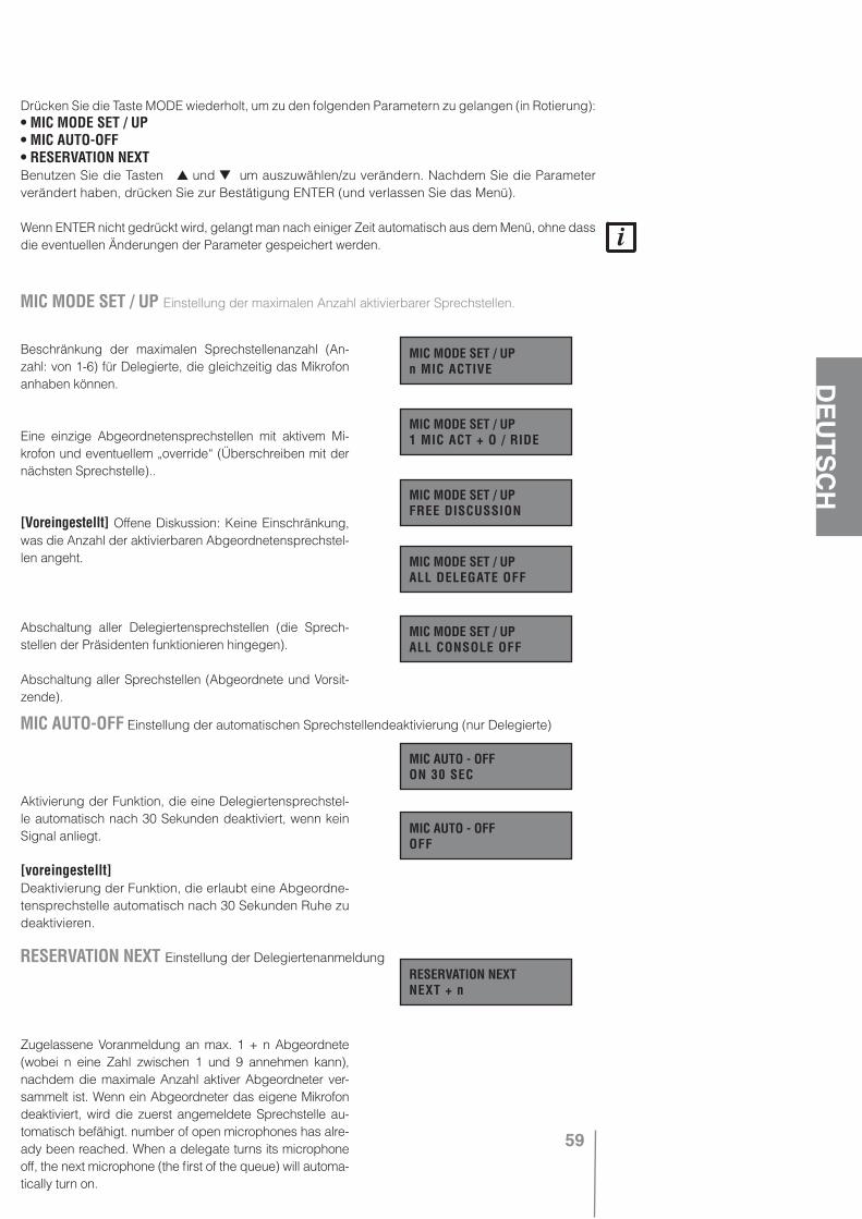
59
DEU
TSCH
Drücken Sie die Taste MODE wiederholt, um zu den folgenden Parametern zu gelangen (in Rotierung): • MIC MODE SET / UP• MIC AUTO-OFF• RESERVATION NEXTBenutzen Sie die Tasten und um auszuwählen/zu verändern. Nachdem Sie die Parameter verändert haben, drücken Sie zur Bestätigung ENTER (und verlassen Sie das Menü).
Wenn ENTER nicht gedrückt wird, gelangt man nach einiger Zeit automatisch aus dem Menü, ohne dass die eventuellen Änderungen der Parameter gespeichert werden.
Beschränkung der maximalen Sprechstellenanzahl (An-zahl: von 1-6) für Delegierte, die gleichzeitig das Mikrofon anhaben können.
Eine einzige Abgeordnetensprechstellen mit aktivem Mi-krofon und eventuellem „override“ (Überschreiben mit der nächsten Sprechstelle)..
[Voreingestellt] Offene Diskussion: Keine Einschränkung, was die Anzahl der aktivierbaren Abgeordnetensprechstel-len angeht.
Abschaltung aller Delegiertensprechstellen (die Sprech-stellen der Präsidenten funktionieren hingegen).
Abschaltung aller Sprechstellen (Abgeordnete und Vorsit-zende).
Aktivierung der Funktion, die eine Delegiertensprechstel-le automatisch nach 30 Sekunden deaktiviert, wenn kein Signal anliegt.
[voreingestellt]Deaktivierung der Funktion, die erlaubt eine Abgeordne-tensprechstelle automatisch nach 30 Sekunden Ruhe zu deaktivieren.
Zugelassene Voranmeldung an max. 1 + n Abgeordnete (wobei n eine Zahl zwischen 1 und 9 annehmen kann), nachdem die maximale Anzahl aktiver Abgeordneter ver-sammelt ist. Wenn ein Abgeordneter das eigene Mikrofon deaktiviert, wird die zuerst angemeldete Sprechstelle au-tomatisch befähigt. number of open microphones has alre-ady been reached. When a delegate turns its microphone off, the next microphone (the first of the queue) will automa-tically turn on.
MIC MODE SET / UP Einstellung der maximalen Anzahl aktivierbarer Sprechstellen.
MIC MODE SET / UP n MIC ACTIVE
MIC MODE SET / UP 1 MIC ACT + O / RIDE
MIC MODE SET / UP FREE DISCUSSION
MIC MODE SET / UP ALL DELEGATE OFF
MIC MODE SET / UP ALL CONSOLE OFF
MIC AUTO-OFF Einstellung der automatischen Sprechstellendeaktivierung (nur Delegierte)
MIC AUTO - OFF ON 30 SEC
MIC AUTO - OFF OFF
RESERVATION NEXT Einstellung der DelegiertenanmeldungRESERVATION NEXT NEXT + n
60
DEU
TSCH
Einen einzelnen Abgeordneten wird die Anmeldung zugewilligt, nachdem er die maximale Anzahl aktiver Abgeordneter zusammengetragen hat. Wenn ein Abge-ordneter sein eigenes Mikrofon deaktiviert, ist die voran-gemeldete Sprechstelle automatisch aktiviert.
[voreingestellt] Deaktivierung der Voranmeldung-sfunktion der Abgeordneten.
Durch die Taste SET, gelangt man auf das Konfigura-tionsmenü, wo man einen Moment drauf drückt. An-schließend gelangt man auf den Display LCD und es erscheint der folgende Text: Um auf das Menü zu gelangen, ist es erstmals nötig die Taste SET für mindestens 3 Sekunden gedrückt zu halten. Anschließend drückt man die Taste SET, um die folgenden Parameter zu visu-alisieren (in Rotation):
• INTERPRETATION• A & B INPUT MODE• VOX / CMD INPUT A• VOX / CMD INPUT B• CHIME ON CHAIRM• CONSOLE OUT JACKNutzen Sie die Tasten und um auszuwählen/zu ändern. Nachdem die Parameter geändert wurden, drücken Sie zur Bestätigung ENTER (und gehen Sie aus dem Menü raus)!
Nach Drücken von ENTER wird das System neu initiiert und die Diskussion unterbrochen, um die Neueinstellungen zu bestätigen.
Die Sequenzübersetzung wird aktiviert, wenn eine der zwei Übersetzungssprechstellen, um Aktivierung bittet (durch Deaktivierung der anderen) die übersetzte Spra-che (der Dolmetscher) wird den 3 Audioausgängen des Systems zugeschickt (Sprechstellenleitung, MAIN OUT und der Ausgang für Telekonferenz). Wenn der Dol-metscher das eigene Mikrofon deaktiviert, wird auf die 3 Audiosystemausgänge das gemischte Signal der Spre-chstellen verschickt IN A, IN B, IN PLAY, (und die Klingel „Chime“)..
Aktivierte Simultanübersetzung: Wenn eine der zwei Über-setzungssprechstellen, die Aktivierung erbittet (die ande-re wird deaktiviert), ist die übersetzte Sprache nur auf den zwei Kopfhörerausgängen Jack der Sprechstellen ver-fügbar (die internen Kopfhörer der Sprechstellen sind de-aktiviert). Den 2 anderen Systemausgängen (MAIN OUT und dem Ausgang für Telekonferenz) wird ein gemischtes Signal der Sprechstelle zugesendet, IN A, IN B, IN PLAY (und die Glocke „Chime“)
RESERVATION NEXT NEXT
RESERVATION NEXT OFF
PRESS KEY 3 sec ENTER INIT SYS
INTERPRETATION Einstellung der Übersetzungsart (sequentiell/ simultan/ deaktiviert).
INTERPRETATION SEQUENTIAL
INTERPRETATION SIMULTANEOUS
INTERPRETATION OFF
IMPORTANT Durch Auswahl der Simultanübersetzungsmodalität ist es unheimlich wichtig ein Verstärkungsaudiosystem zu verknüpfen (an den Ausgang „LINE LEBEL MAIN OUT“ der zentralen Einheit DMU 6100), um die Originalsprache hören zu können.
[voreingestellt] Deaktivierte Übersetzung: den 3 Ausgängen des Systems (Sprechstellenleitung, MAIN OUT und Telekonferenz) wird das gemischte Signal der Sprechstelle verschickt IN A, IN B, IN PLAY (und die Glocke „Chime“).
61
DEU
TSCH
INTERPRETATION Einstellung der Übersetzungsart (sequentiell/ simultan/ deaktiviert).
[voreingestellt] Die Eingänge A, B und das Signal der Sprechstellen sind
vermischt.
Die Eingänge A und B sind untereinander blockiert (der
erste aktive Eingang schließt den andern aus); ihr Signal
ist mit dem der Sprechstelle vermischt.
Eingang A ist wichtiger als Eingang B. Ihr Signal ist mit
dem der Mikrofone der Sprechstellen vermischt.
Die Eingänge A und B sind vermischt und ihr Signal ist
wichtiger als das der Sprechstellen.
Das Signal der Sprechstellen ist wichtiger als das gemi-
schte aus den Eingängen A und B.
Das Signal der Sprechstellen ist wichtiger als das
vermischte Signal, zusammengesetzt aus Eingang B
und den Sprechstellen.
VOX: innerer Kreislauf, der ein bestehendes Audiosignal an einen Eingang weiterleitet.
[voreingestellt] Der Eingang A ist aktiviert, wenn der ex-terne Befehl abgeschlossen wird (Befehl=Aktivierung) oder wenn das Zeichen automatisch festgestellt wird (akti-ves VOX).
Der Eingang A wird aktiviert, wenn der externe Befehl abgeschlossen wird (Befehl = Aktivierung); ausgeschal-tetes VOX
Der Eingang A wird aktiviert, wenn der externe Befehl offen bleibt (Befehl = “mute“), und wenn das Signal auto-matisch festgestellt wird (angeschaltetes VOX).
Der Eingang A wird aktiviert, wenn der externe Befehl offen bleibt, („command“=“mute“) und wenn das Signal automatisch entnommen wird.
Die Einstellungen sind identisch zu den vorher-gehenden für den Ein-gang MIC/LINE INPUT A (Paramter:“VOX / CMD IN-PUT A“), aber sie beziehen sich auf den Nutzen des Eingangs MIC / LINE INPUT B.
A & B INPUT MODE Einstellung Vorrangigkeit der Audioeingänge MIC/LINE INPUT A und B.
A & B INPUT MODEA mix B mix SYS
A & B INPUT MODE(A lock B) mx SYS
A & B INPUT MODE(A prio B) mx SYS
A & B INPUT MODE(A mx B) prio SYS
A & B INPUT MODESYS prio (A mx B)
VOX / CMD INPUT A VOX Einstellung und Eingangsbefehl Audio MIC/LINE INPUT A
VOX / CMD INPUT ACMD ACT, VOX ACT
VOX / CMD INPUT ACMD ACT, VOX OFF
VOX / CMD INPUT ACMD MUTE, VOX ACT
VOX / CMD INPUT ACMD MUTE, VOX OFF
VOX / CMD INPUT B VOX Einstellung und Befehl des Audioeingangs MIC/ LINE INPUT B
VOX / CMD INPUT BCMD ACT, VOX ACT
VOX / CMD INPUT BCMD ACT, VOX OFF
VOX / CMD INPUT BCMD MUTE, VOX ACT
VOX / CMD INPUT BCMD MUTE, VOX OFF
[voreingestellt]
A & B INPUT MODEA prio (B mx SYS)
62
DEU
TSCH
Die Glocke („chime“) hat für den Vorsitzenden die Fähi-gkeit Vorrangig zu intervenieren.
[voreingestellt] Die Glocke wird deaktiviert (dies betrifft die vorrangige Intervention durch den Vorsitzenden).
[voreingestellt] Auf den Jacksteckern jeder Sprechstel-le, ist das gleiche Rückkehrzeichen für den Lautsprecher vorhanden. Wenn die Kopfhörer benutzt werden, ist der Lautsprecher deaktiviert.
Auf den Jacksteckern einer jeden Sprechstelle, befindet sich das Zeichen für einen eventuellen Anschluss eines Aufnahmegeräts, der Lautsprecher ist nicht deaktiviert.
Auf den Jacksteckern einer jeden Sprechstelle gibt es kein Signal, der Lautsprecher ist nicht deaktiviert.
Bei den Sprechstellen für Dolmetscher sind die Jackstecker immer in der Ausführung HEADPHO-NES (Nutzung für Kopfhörer) eingestellt, abgesehen von der Parametereinstellung „CONSOLE OUT JACK“.Durch Drücken der Taste IN LAUTSTÄRKE, gelangt man ins Einstellungsmenü der Eingangslautstär-ken. Durch wiederholtes Drücken, erhält man die folgenden Parameter (in Rotation). Verwenden Sie die Tasten und , um eine Änderung herbeizuführen (maximales Niveau: 16; voreingestelltes Niveau: 10; Niveau 0: „MUTE“).
Lautstärke der Vorsitzenden- und derAbgeordnetensprechstelle
Lautstärke der Dolmetschersprechstellen
Lautstärke des Eingangs MIC / LINE INPUT A (mit Stecker XLR)
Lautstärke des Eingangs MIC / LINE INPUT B (mit Stecker XLR)
Lautstärke des Eingangs PLAY.
Lautstärker des Eingangs für Telekonferenz.
CHIME ON CHAIRMACTIVE
CHIME ON CHAIRMOFF
CONSOLE OUT JACKHEADPHONES
CONSOLE OUT JACKRECORDING
CONSOLE OUT JACKDISABLED
VOL CONSOLE MIC
VOL INTERPR. MIC
VOLUME INPUT A
VOLUME INPUT B
VOL IN AUX-PLAY
VOL IN TELECONF.
CONSOLE OUT JACK Einstellungen der Jack Ausgänge der Sprechstellen(nur Abgeordnete und Vorsitzende)
CHIME ON CHAIRM Vorrangige Signaleinstellung (Glocke) der Vorsitzendensprechstelle.
IMPORTANT Wenn die Simultanübersetzung vorgesehen ist, behalten Sie das Parameter „CONSOLE OUT JACK“ auf „HEADPHONES“, andernfalls wird es nicht möglich sein die übersetzte Sprache zu hören (über Kopfhörer)
63
DEU
TSCH
Durch Drücken der Taste OUT VOLUME gelangt man ins Einstellungsmenü der Ausgangslautstär-ken; durch wiederholtes Drücken hat man die folgenden Parameter (in Rotation). Verwenden Sie die Tasten und , um eine Änderung herbeizuführen (maximales Niveau: 16; voreingestelltes Niveau: 10; Niveau 0: „MUTE“).
Interne Lautsprecherlautstärke der Sprechstellen
Lautstärke des Hauptaudioausgangs MAIN OUT
Durch Drücken der Taste ENTER gelangt man aus der Fehlerdarstellung
Während der Adressierung:
CHRM INIT ERROR: Es gibt mehr als drei Vorsitzendensprechstellenim System
DEL INIT ERROR: Es gibt mehr als 30 Sprechstellen in einer Leitung.
N.B.: Wenn (in der zentralen Einheit DMU 6100) die Anschlüsse der Abgeordneten-/ Vorsitzenden- und Dolmetscherleitungen eingefügt werden, ist das NON System fähig es hervorzuheben. De-shalb wird keine Signalisierung auf dem LCD Display angezeigt.
Während des Betriebs:CONSOLE ERROR: Eine Vorsitzenden- oder Abgeordne-tensprechstelle funktioniert nicht mehr (z.B.: Leitung 2, Position 15).
CONSOLE ERROR: Eine Dolmetschsprechstelle funktio-niert nicht mehr (z.B.: Dolmetscher Nr. 2).
Position 1 ist die erste Sprechstelle einer direkt an die Zentrale DMU 6100 angeschlossenen Lei-tung; Position 30 ist die letzte Sprechstelle einer Leitung.
Für den Fall, dass es mehr Schäden gibt, zeigt der Display LCD nur einen einzigen Fehler auf einmal an, sobald das Gerät eingeschaltet ist. Deswegen muss der Auslöser des ersten Fehlers beseitigt werden, um die Darstellung des folgenden Fehlers zu erhalten (falls eingetroffen) nachdem das System erneut beschädigt wurde.
Diese Message könnte nach Einschalten des Systems und des Aufzeigens der Sprechstellenanzahl auftauchen, für den Fall, dass es während der Lesung des EEPROM Probleme gibt (interner Speicher). Ineinem solchen Fall werden immer die ersten Parameter wiederhergestellt und die technische Wartung wird nötig.
Stromschäden und Schmelzsicherungen(die technische Wartung ist nötig):
Interner Stromschaden 12 V
VOL CONSOLE SPKR
VOL MAIN OUT
CONSOLE OUT JACK Einstellungen der Jack Ausgänge der Sprechstellen(nur Abgeordnete und Vorsitzende)
ERROR MELDUNGEN
CHRM INIT ERRORPRESS SET, ENTER
DEL INIT ERRORPRESS SET, ENTER
CONSOLE ERRORLINE 2 POS.15
CONSOLE ERRORINTERPRETER 2
DEFAULT MODESERVICE REQUIRED
12V POWER FAULTSERVICE REQUIRED

64
DEU
TSCH
1
Schaden interner Strom 24 V
Schaden externer Strom 24 V (DPS 6202)
Schaden der Schmelzsicherungsleitungen der Sprechstellen 1 und 2.
Schaden der Schmelzsicherungsleitungen der Sprechstellen 3 und 4 (DEC 6104)
Schaden der Schmelzsicherungsleitungen der Sprechstellen 5 und 6 (DEC 6104)
OBERES PANEEL
1 Mikrofon mit Leuchtring.2 Interner Lautsprecher.3 Zweifarb LED, der die Farben rot, grün, gelb
(rot mehr grün) visualisiert, je nach Einstel-lung der Sprechstelle (Vorsitzender, Abge-ordneter, Dolmetscher).
4 Kleine und große Taste, deren Funktion von der Sprechstelleneinstellung abhängt (Vorsit-zender, Abgeordneter, Dolmetscher).
5 Tasten für die Lautstärkenregulierung des in-ternen Lautsprechers.
SEITLICHE PANEELEEs gibt zwei Jack Stecker 3,5 mm - 1/8” (einer links und einer rechts) für die Kopfhörer / Aufnahmegerät.
HINTERES PANEEL
1 IN Anschluss RJ zu 10 Polen für den Eingang des Spezialkabels (zu 10 Polen), der von der vorherigen Sprechstelle oder der zentralen Einheit DMU 6100 stammt.
2 OUT Anschluss RJ zu 10 Polen für den Aus-gang des Spezialkabels (zu 10 Polen) direkt zur folgenden Sprechstelle.
3 Mikroschalter für die Sprechstellenkonfigu-rierung als Vorsitzender, Abgeordneter oder Dolmetscher.
4 Knopf zum Abschluss der zu aktivierenden Leitung der letzten Sprechstelle.
24 V POWER FAULTSERVICE REQUIRED
MIKROFONSPRECHSTELLE DMS 6410
EXT 24 V PWR FLTSERVICE REQUIRED
L1&L2 FUSE FAULTSERVICE REQUIRED
L3&L4 FUSE FAULTSERVICE REQUIRED
L5&L6 FUSE FAULTSERVICE REQUIRED
4
3 2
5
4 3 2 1
Delegate console
Chairman console
Interpreter console
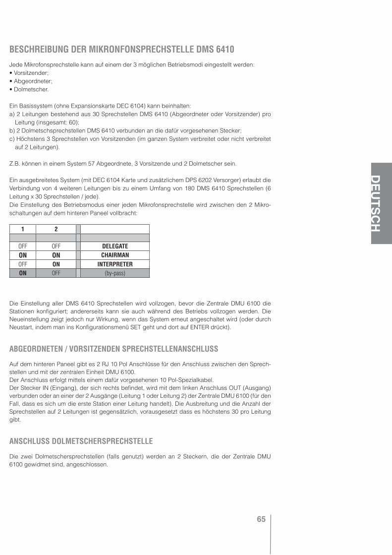
65
DEU
TSCH
BESCHREIBUNG DER MIKRONFONSPRECHSTELLE DMS 6410Jede Mikrofonsprechstelle kann auf einem der 3 möglichen Betriebsmodi eingestellt werden:• Vorsitzender;• Abgeordneter;• Dolmetscher.
Ein Basissystem (ohne Expansionskarte DEC 6104) kann beinhalten:a) 2 Leitungen bestehend aus 30 Sprechstellen DMS 6410 (Abgeordneter oder Vorsitzender) pro
Leitung (insgesamt: 60);b) 2 Dolmetschsprechstellen DMS 6410 verbunden an die dafür vorgesehenen Stecker;c) Höchstens 3 Sprechstellen von Vorsitzenden (im ganzen System verbreitet oder nicht verbreitet
auf 2 Leitungen).
Z.B. können in einem System 57 Abgeordnete, 3 Vorsitzende und 2 Dolmetscher sein.
Ein ausgebreitetes System (mit DEC 6104 Karte und zusätzlichem DPS 6202 Versorger) erlaubt die Verbindung von 4 weiteren Leitungen bis zu einem Umfang von 180 DMS 6410 Sprechstellen (6 Leitung x 30 Sprechstellen / jede).Die Einstellung des Betriebsmodus einer jeden Mikrofonsprechstelle wird zwischen den 2 Mikro-schaltungen auf dem hinteren Paneel vollbracht:
Die Einstellung aller DMS 6410 Sprechstellen wird vollzogen, bevor die Zentrale DMU 6100 die Stationen konfiguriert; andererseits kann sie auch während des Betriebs vollzogen werden. Die Neueinstellung zeigt jedoch nur Wirkung, wenn das System erneut angeschaltet wird (oder durch Neustart, indem man ins Konfigurationsmenü SET geht und dort auf ENTER drückt).
ABGEORDNETEN / VORSITZENDEN SPRECHSTELLENANSCHLUSS
Auf dem hinteren Paneel gibt es 2 RJ 10 Pol Anschlüsse für den Anschluss zwischen den Sprech-stellen und mit der zentralen Einheit DMU 6100.Der Anschluss erfolgt mittels einem dafür vorgesehenen 10 Pol-Spezialkabel.Der Stecker IN (Eingang), der sich rechts befindet, wird mit dem linken Anschluss OUT (Ausgang) verbunden oder an einer der 2 Ausgänge (Leitung 1 oder Leitung 2) der Zentrale DMU 6100 (für den Fall, dass es sich um die erste Station einer Leitung handelt). Die Ausbreitung und die Anzahl der Sprechstellen auf 2 Leitungen ist gegensätzlich, vorausgesetzt dass es höchstens 30 pro Leitung gibt.
ANSCHLUSS DOLMETSCHERSPRECHSTELLE
Die zwei Dolmetschersprechstellen (falls genutzt) werden an 2 Steckern, die der Zentrale DMU 6100 gewidmet sind, angeschlossen.
1 2
OFF OFF DELEGATEON ON CHAIRMANOFF ON INTERPRETERON OFF (by-pass)
66
DEU
TSCH
ENDUNG DER LEITUNGEN
Für eine ordnungsgemäße “Endung” der Leitungen, geht man wie folgt vor:• Auf der letzten Sprechstelle (Abgeordneter oder Vorsitzender) einer Leitung ist es nötig (ON) den
zugehörigen Schalter LINE TERMINATION, der sich hinten befindet, zu drücken. Auf den restli-chen Sprechstellen (einer jeden Leitung), muss der Schalter auf OFF geschaltet sein (erhoben). Für den Fall, dass eine der Sprechstellen während der Strecke die Schaltung LINE TERMINA-TION fälschlicherweise auf (ON) während der Konfiguration gedrückt hat, werden alle vorherigen Sprechstellen wieder erkannt (Anschaltung des Leuchtringes), während hingegen die folgenden Sprechstellen von der zentralen Einheit DMU 6100 nicht wahrgenommen werden.
• Wenn (zumindest) eine Dolmetschsprechstelle verwendet wird, muss man sich auf der zentralen Einheit DMU 6100 versichern, dass sich der zugehörige Mikroschalter der „Endung“ auf OFF befindet (Dolmetscher anwesend). Auf der Dolmetschsprechstelle ist es hingegen irrelevant, ob man den zugehörigen Schalter LINE TERMINATION drückt.
• Wenn eine Dolmetschsprechstelle nicht benutzt wird, muss man die jeweilige nicht genutzte Lei-tung deaktivieren, indem man den zugehörigen Mikroschalter auf der Zentrale DMU 6100 auf ON schaltet.
JACK STECKER
Auf den zwei Seiten der Sprechstelle DMS 6410, befinden sich 2 Jack Ausgänge (3,5 mm - 1/8”; einer links der andere rechts)
Ihr Ausgangssignal hängt von der Konfiguration der zentralen Einheit DMU 6100 und der Betriebsmo-dalität der Station (Abgeordneter / Vorsitzender / Dolmetscher) ab.
Mögliche Konfigurationen sind folgende (Parameter “CONSOLE OUT JACK” im Menü SET):• HEADPHONES Das Signal im Ausgang wird für die Nutzung der Kopfhörer optimiert, durch Einfügen
der Kopfhörer wird der interne Lautsprecher ausgeschaltet und die Lautstärke kann mit den jewei-ligen Tasten zwischen 0 und dem maximal eingestellten Wert auf der Zentrale DMU 6100 reguliert werden.
• RECORDING Das Signal im Ausgang wird für die Nutzung eines Aufnahmegeräts optimiert, und durch Einfügen eines der 2 Jacks, wird der Lautsprecher nicht deaktiviert. Die Kontrolle der Lautstär-ke wird befähigt und kann zwischen ca. 30% und 100% eingestellt werden, aber die Lautstärke kann nicht auf Null heruntergedreht werden. Die Lautstärkeneinstellung hat auf der Zentraleneinheit DMU 6100 keine Wirkung.
• DISABLED Auf den Ausgängen Jack gibt es kein Signal (nur für Vorsitzende oder Abgeordnete). Der interne Lautsprecher funktioniert hingegen.
Auf den Dolmetschsprechstellen befinden sich die Jack Stecker immer auf HEADPHONES (Benut-zung der Kopfhörer) abgesehen von der Parametereinstellung “CONSOLE OUT JACK” der Zentrale DMU 6100, eine Einstellung, die nur für Vorsitzende- und Abgeordnetensprechstellen gilt, wohinge-gen die Lautstärke immer regulierbar ist zwischen Null und dem maximal eingestellten Niveau der zentralen Einheit.
OBERES PANEELEs gibt zwei Lautstärkentasten, 2 Auswahltasten und einen zweifarben LED, deren Funktion von der Betriebsmodalität abhängt (Abgeordneter, Vorsitzender, Dolmetscher) und von der Konfiguration der Zentrale DMU 6100.
INTERNER LAUTSPRECHERDie Tasten für die Lautstärkkontrolle erlauben auch nicht die Regulierung zwischen Null und dem maximal eingestellten Niveau der Zentrale DMU 6100. Der Lautsprecher ist während der Simultanü-bersetzung immer abgeschaltet,wenn das Mikrofon der Sprechstelle angeschaltet ist, und auf HEADPHONES Einstellung, wenn die Kopfhörer in einer der zwei Jack Stecker eingefügt sind.
Wichtig Wenn die Simultanübersetzung vorgesehen ist, behalten Sie den Parameter“CONSOLE OUT JACK” auf “HEADPHONES”, ansonsten wird es nicht möglich sein die übersetzte Sprache zu hören (über Kopfhörer).
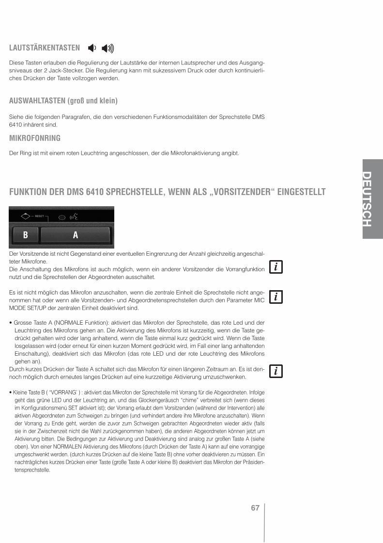
67
DEU
TSCH
LAUTSTÄRKENTASTEN
Diese Tasten erlauben die Regulierung der Lautstärke der internen Lautsprecher und des Ausgang-sniveaus der 2 Jack-Stecker. Die Regulierung kann mit sukzessivem Druck oder durch kontinuierli-ches Drücken der Taste vollzogen werden.
AUSWAHLTASTEN (groß und klein)
Siehe die folgenden Paragrafen, die den verschiedenen Funktionsmodalitäten der Sprechstelle DMS 6410 inhärent sind.
MIKROFONRING
Der Ring ist mit einem roten Leuchtring angeschlossen, der die Mikrofonaktivierung angibt.
Der Vorsitzende ist nicht Gegenstand einer eventuellen Eingrenzung der Anzahl gleichzeitig angeschal-teter Mikrofone.Die Anschaltung des Mikrofons ist auch möglich, wenn ein anderer Vorsitzender die Vorrangfunktion nutzt und die Sprechstellen der Abgeordneten ausschaltet.
Es ist nicht möglich das Mikrofon anzuschalten, wenn die zentrale Einheit die Sprechstelle nicht ange-nommen hat oder wenn alle Vorsitzenden- und Abgeordnetensprechstellen durch den Parameter MIC MODE SET/UP der zentralen Einheit deaktiviert sind.
• Grosse Taste A (NORMALE Funktion): aktiviert das Mikrofon der Sprechstelle, das rote Led und der Leuchtring des Mikrofons gehen an. Die Aktivierung des Mikrofons ist kurzzeitig, wenn die Taste ge-drückt gehalten wird oder lang anhaltend, wenn die Taste einmal kurz gedrückt wird. Wenn die Taste losgelassen wird (oder erneut für einen kurzen Moment gedrückt wird, im Fall einer lang anhaltenden Einschaltung), deaktiviert sich das Mikrofon (das rote LED und der rote Leuchtring des Mikrofons gehen an).
Durch kurzes Drücken der Taste A schaltet sich das Mikrofon für einen längeren Zeitraum an. Es ist den-noch möglich durch erneutes langes Drücken auf eine kurzzeitige Aktivierung umzuschwenken.
• Kleine Taste B ( “VORRANG’ ) : aktiviert das Mikrofon der Sprechstelle mit Vorrang für die Abgeordneten. Infolge geht das grüne LED und der Leuchtring an, und das Glockengeräusch “chime” verbreitet sich (wenn dieses im Konfigurationsmenü SET aktiviert ist); der Vorrang erlaubt dem Vorsitzenden (während der Intervention) alle aktiven Abgeordneten zum Schweigen zu bringen (und verhindert andere ihre Mikrofone anzuschalten). Wenn der Vorrang zu Ende geht, werden die zuvor zum Schweigen gebrachten Abgeordneten wieder aktiv (falls sie in der Zwischenzeit nicht die Wahl zurückgenommen haben), die anderen Abgeordneten können jetzt um Aktivierung bitten. Die Bedingungen zur Aktivierung und Deaktivierung sind analog zur großen Taste A (siehe oben). Von einer NORMALEN Aktivierung des Mikrofons (durch Drücken der Taste A) kann auf eine vorrangige umgeschwenkt werden. (durch kurzes Drücken auf die kleine Taste B) ohne vorher deaktivieren zu müssen. Ein nachträgliches kurzes Drücken einer Taste (große Taste A oder kleine B) deaktiviert das Mikrofon der Präsiden-tensprechstelle.
FUNKTION DER DMS 6410 SPRECHSTELLE, WENN ALS „VORSITZENDER“ EINGESTELLT
AB
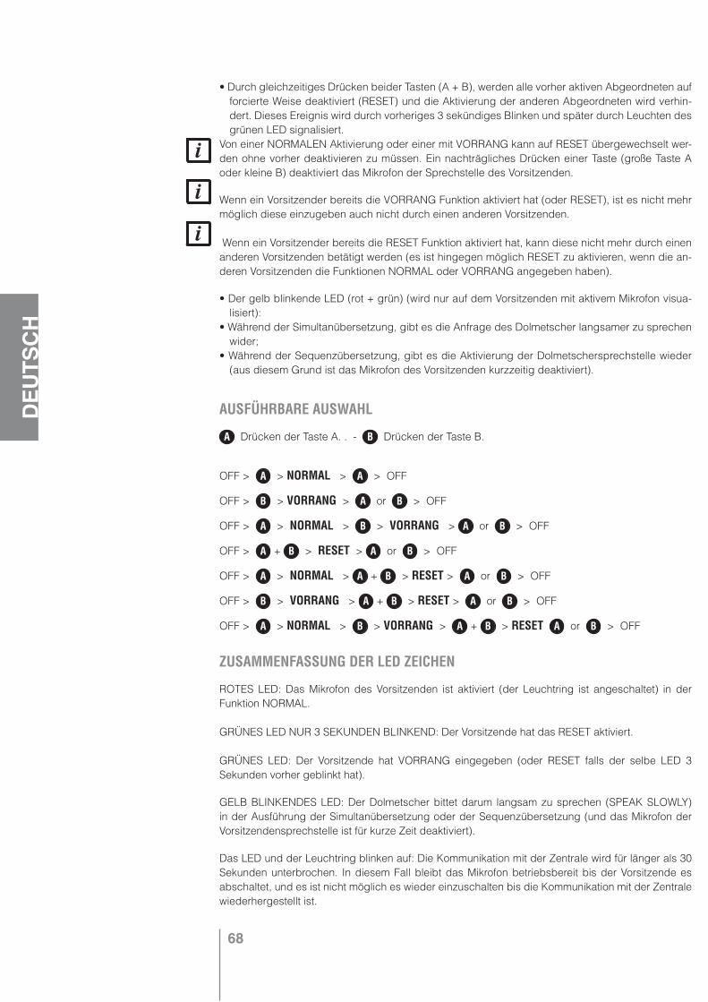
68
DEU
TSCH
• Durch gleichzeitiges Drücken beider Tasten (A + B), werden alle vorher aktiven Abgeordneten auf forcierte Weise deaktiviert (RESET) und die Aktivierung der anderen Abgeordneten wird verhin-dert. Dieses Ereignis wird durch vorheriges 3 sekündiges Blinken und später durch Leuchten des grünen LED signalisiert.
Von einer NORMALEN Aktivierung oder einer mit VORRANG kann auf RESET übergewechselt wer-den ohne vorher deaktivieren zu müssen. Ein nachträgliches Drücken einer Taste (große Taste A oder kleine B) deaktiviert das Mikrofon der Sprechstelle des Vorsitzenden.
Wenn ein Vorsitzender bereits die VORRANG Funktion aktiviert hat (oder RESET), ist es nicht mehr möglich diese einzugeben auch nicht durch einen anderen Vorsitzenden.
Wenn ein Vorsitzender bereits die RESET Funktion aktiviert hat, kann diese nicht mehr durch einen anderen Vorsitzenden betätigt werden (es ist hingegen möglich RESET zu aktivieren, wenn die an-deren Vorsitzenden die Funktionen NORMAL oder VORRANG angegeben haben).
• Der gelb blinkende LED (rot + grün) (wird nur auf dem Vorsitzenden mit aktivem Mikrofon visua-lisiert):
• Während der Simultanübersetzung, gibt es die Anfrage des Dolmetscher langsamer zu sprechen wider;
• Während der Sequenzübersetzung, gibt es die Aktivierung der Dolmetschersprechstelle wieder (aus diesem Grund ist das Mikrofon des Vorsitzenden kurzzeitig deaktiviert).
AUSFÜHRBARE AUSWAHL
A Drücken der Taste A. . - B Drücken der Taste B.
OFF > A > NORMAL > A > OFF
OFF > B > VORRANG > A or B > OFF
OFF > A > NORMAL > B > VORRANG > A or B > OFF
OFF > A + B > RESET > A or B > OFF
OFF > A > NORMAL > A + B > RESET > A or B > OFF
OFF > B > VORRANG > A + B > RESET > A or B > OFF
OFF > A > NORMAL > B > VORRANG > A + B > RESET A or B > OFF
ZUSAMMENFASSUNG DER LED ZEICHEN
ROTES LED: Das Mikrofon des Vorsitzenden ist aktiviert (der Leuchtring ist angeschaltet) in der Funktion NORMAL.
GRÜNES LED NUR 3 SEKUNDEN BLINKEND: Der Vorsitzende hat das RESET aktiviert.
GRÜNES LED: Der Vorsitzende hat VORRANG eingegeben (oder RESET falls der selbe LED 3 Sekunden vorher geblinkt hat).
GELB BLINKENDES LED: Der Dolmetscher bittet darum langsam zu sprechen (SPEAK SLOWLY) in der Ausführung der Simultanübersetzung oder der Sequenzübersetzung (und das Mikrofon der Vorsitzendensprechstelle ist für kurze Zeit deaktiviert).
Das LED und der Leuchtring blinken auf: Die Kommunikation mit der Zentrale wird für länger als 30 Sekunden unterbrochen. In diesem Fall bleibt das Mikrofon betriebsbereit bis der Vorsitzende es abschaltet, und es ist nicht möglich es wieder einzuschalten bis die Kommunikation mit der Zentrale wiederhergestellt ist.
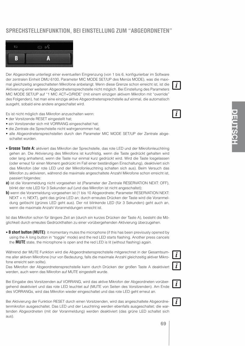
69
DEU
TSCH
Der Abgeordnete unterliegt einer eventuellen Eingrenzung (von 1 bis 6, konfigurierbar im Software der zentralen Einheit DMU 6100, Parameter MIC MODE SET/UP des Menüs MODE), was die maxi-mal gleichzeitig angeschalteten Mikrofone anbelangt. Wenn diese Grenze schon erreicht ist, ist die Aktivierung einer weiteren Abgeordnetensprechstelle nicht möglich. Bei Einstellung des Parameters MIC MODE SET/UP auf “1 MIC ACT+O/RIDE” (mit einem einzigen aktivem Mikrofon mit “override” des Folgenden), hat man eine einzige aktive Abgeordnetensprechstelle auf einmal, die automatisch ausgeht, sobald eine andere angeschaltet wird.
Es ist nicht möglich das Mikrofon anzuschalten wenn:• der Vorsitzende RESET eingestellt hat;• ein Vorsitzender sich mit VORRANG eingeschaltet hat;• die Zentrale die Sprechstelle nicht wahrgenommen hat;• alle Abgeordnetensprechstellen durch den Parameter MIC MODE SET/UP der Zentrale abge-
schaltet wurden.
• Grosse Taste A: aktiviert das Mikrofon der Sprechstelle, das rote LED und der Mikrofonleuchtring gehen an. Die Aktivierung des Mikrofons ist kurzfristig, wenn die Taste gedrückt gehalten wird oder lang anhaltend, wenn die Taste nur einmal kurz gedrückt wird. Wird die Taste losgelassen (oder erneut für einen Moment gedrückt im Fall einer beständigen Einschaltung), deaktiviert sich das Mikrofon (der rote LED und der Mikrofonleuchtring schalten sich aus). Beim Versuch das Mikrofon zu aktivieren, während die maximale angeschaltete Anzahl Mikrofone schon erreicht ist, passiert folgendes:
a) ist die Voranmeldung nicht vorgesehen ist (Parameter der Zentrale RESERVATION NEXT: OFF), blinkt der rote LED für 3 Sekunden auf (und das Mikrofon ist nicht angeschaltet);
b) wenn die Voranmeldung vorgesehen ist (1 bis 10 Abgeordnete; Parameter RESERVATION NEXT: NEXT + n; NEXT), geht das grüne LED an; durch erneutes Drücken der Taste wird die Voranmel-dung gelöscht (grünes LED geht aus). Der rot blinkende LED (für 3 Sekunden) geht auch an, wenn die maximale Anzahl Voranmeldungen erreicht ist.
Ist das Mikrofon schon für längere Zeit an (durch ein kurzes Drücken der Taste A), besteht die Mö-glichkeit durch erneutes Gedrückthalten zu einer vorübergehenden Aktivierung überzugehen.
• B short button (MUTE): it momentary mutes the microphone (if this has been previously opened by using the A long button in “toggle” mode) and the red LED starts flashing. Another press cancels the MUTE state, the microphone is open and the red LED is lit (without flashing) again.
Während der MUTE Funktion wird die Abgeordnetensprechstelle mitgerechnet in der Gesamtsum-me aller aktiven Mikrofone (nur von Bedeutung, falls die maximale Anzahl gleichzeitig aktiver Mikro-fone erreicht sein sollte). Das Mikrofon der Abgeordnetensprechstelle kann durch Drücken der großen Taste A deaktiviert werden, auch wenn das Mikrofon auf MUTE eingestellt wurde.
Bei Eingabe des Vorsitzenden auf VORRANG, wird das aktive Mikrofon der Abgeordneten vorüber-gehend deaktiviert und das rote LED leuchtet auf (MUTE von Seiten des Vorsitzenden). Am Ende des VORRANGs, wird das Mikrofon wieder eingeschaltet und das rote LED geht erneut an.
Bei Aktivierung der Funktion RESET durch einen Vorsitzenden, wird das angeschaltete Abgeordne-tenmikrofon ausgeschaltet. Das LED und der Leuchtring werden ebenfalls ausgeschaltet; die war-tenden Abgeordneten (mit der Voranmeldung) werden deaktiviert (das grüne LED schaltet sich aus).
SPRECHSTELLENFUNKTION, BEI EINSTELLUNG ZUM “ABGEORDNETEN”
AB

70
DEU
TSCH
• Das gelbe LED (rot + grün) blinkt auf:• während der Simultanübersetzung, gibt es die Aufforderung des Dolmetschers wieder langsamer
zu sprechen;• während der nachgeordneten Übersetzung, gibt es die Aktivierung der Dolmetschsprechstelle
wieder (und aus diesem Grund ist das Mikrofon des Abgeordneten vorübergehend deaktiviert).Das gelb blinkende LED erscheint nur in den Abgeordnetensprechstellen mit aktivem Mikrofon
oder solchen, die auf MUTE eingestellt sind. In den nicht aktiven oder denen die vorangemeldet werden (mit grünem LED wenn angeschaltet) geschieht nichts.
FUNKTION MIC AUTO-OFF (NUR ABGEORDNETE)
Bei Einschaltung der Funktion MIC AUTO-OFF (in der Konfigurierung der Zentrale), wird nach 30 fortlaufenden Sekunden (mit aktivem Mikrofon), in denen die Stimme des Abgeordneten nicht wie-dergegeben wird, das entsprechende Mikrofon automatisch ausgeschaltet. Jedes Mal, wo der Ab-geordnete in den letzten 5 Sekunden, die ihm bleiben, zu sprechen beginnt, werden darüber hinaus 10 Sekunden zur Verfügung gestellt, bevor das Mikrofon deaktiviert wird.
Wenn das Mikrofon des Abgeordneten vorübergehend deaktiviert wird (Funktion MUTE, die vom Vorsitzenden oder vom selben Abgeordneten eingegeben wird), ist die Funktion MIC AUTO-OFF nicht aktiviert. Dies gilt selbst während der Vorgabe der nachgeordneten Übersetzung (bei Ein-schaltung einer Dolmetschersprechstelle, um die Abgeordneten zum Schweigen zu bringen).
ZUSAMMENFASSUNG DER SIGNALISIERUNGEN MITTELS LED
ROTES LED BLINKT NUR 3 SEKUNDEN AUF: Der Versuch das Mikrofon anzuschalten ist verge-blich (der Leuchtring geht nicht an). Das Mikrofon hat sich nicht aktiviert und man hat nicht mal die Voranmeldung bekommen, weil die maximale Anzahl gleichzeitig angeschalteter Abgeordneten-sprechstellen erreicht ist (und auch die Voranmeldung steht nicht zur Verfügung) oder ein Vorsitzen-der zieht Nutzen aus der Einstellung VORRANG (oder hat RESET angeschaltet).
GRÜNES LED: Der Versuch das Mikrofon zu aktivieren ist vergeblich (der Leuchtring geht nicht an), weil die maximale Anzahl gleichzeitig angeschalteter Abgeordnetensprechstellen erreicht ist, aber das grün aktivierte LED, signalisiert, dass die Voranmeldung angenommen wurde.
ROTES LED: Das Sprechstellenmikrofon ist aktiviert (der Leuchtring geht an).
ROT BLINKENDES LED: Die Abgeordnetensprechstelle wird aktiviert, aber das Mikrofon ist vorüber-gehend ausgeschaltet (MUTE). Mögliche Ursachen: die kleine Taste B wurde gedrückt (MUTE) oder ein Vorsitzender zieht Nutzen aus dem VORRANG; in jenem Fall wird der Abgeordnete nicht reden können sondern nur eventuell das eigene Mikrofon ausschalten können oder darauf warten, dass der Vorsitzende den VORRANG löscht.
GELB BLINKENDES LED: Der Dolmetscher bittet in der Ausführungsart der Simultanübersetzung oder nachfolgenden Übersetzung darum, dass langsam gesprochen wird (SPEAK SLOWLY) (und das Mikrofon der Abgeordnetensprechstelle ist vorübergehend abgeschaltet).
DAS LED und der Leuchtring gehen aus, ohne dass der Abgeordnete einschreiten muss, indem er eine Taste drückt: Die MIC AUTO-OFF Funktion hat das Mikrofon nach einiger Zeit automatisch ausgeschaltet oder ein Vorsitzender hat RESET eingegeben.
Das LED und der Leuchtring blinken: die Kommunikation mit der Zentrale ist seit mehr als 30 Sekun-den unterbrochen. In solch einem Fall wird das Mikrofon ausgeschaltet und es ist nicht möglich es wieder einzuschalten bis die Kommunikation mit der zentralen Einheit wiederhergestellt ist.
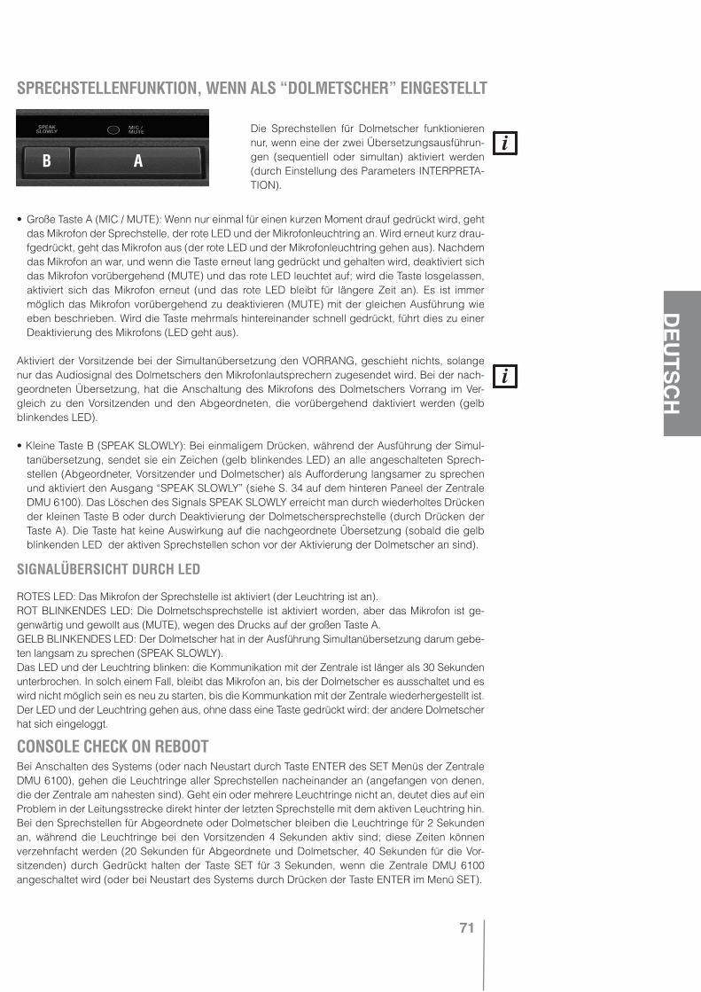
71
DEU
TSCH
Die Sprechstellen für Dolmetscher funktionieren nur, wenn eine der zwei Übersetzungsausführun-gen (sequentiell oder simultan) aktiviert werden (durch Einstellung des Parameters INTERPRETA-TION).
• Große Taste A (MIC / MUTE): Wenn nur einmal für einen kurzen Moment drauf gedrückt wird, geht das Mikrofon der Sprechstelle, der rote LED und der Mikrofonleuchtring an. Wird erneut kurz drau-fgedrückt, geht das Mikrofon aus (der rote LED und der Mikrofonleuchtring gehen aus). Nachdem das Mikrofon an war, und wenn die Taste erneut lang gedrückt und gehalten wird, deaktiviert sich das Mikrofon vorübergehend (MUTE) und das rote LED leuchtet auf; wird die Taste losgelassen, aktiviert sich das Mikrofon erneut (und das rote LED bleibt für längere Zeit an). Es ist immer möglich das Mikrofon vorübergehend zu deaktivieren (MUTE) mit der gleichen Ausführung wie eben beschrieben. Wird die Taste mehrmals hintereinander schnell gedrückt, führt dies zu einer Deaktivierung des Mikrofons (LED geht aus).
Aktiviert der Vorsitzende bei der Simultanübersetzung den VORRANG, geschieht nichts, solange nur das Audiosignal des Dolmetschers den Mikrofonlautsprechern zugesendet wird. Bei der nach-geordneten Übersetzung, hat die Anschaltung des Mikrofons des Dolmetschers Vorrang im Ver-gleich zu den Vorsitzenden und den Abgeordneten, die vorübergehend daktiviert werden (gelb blinkendes LED).
• Kleine Taste B (SPEAK SLOWLY): Bei einmaligem Drücken, während der Ausführung der Simul-tanübersetzung, sendet sie ein Zeichen (gelb blinkendes LED) an alle angeschalteten Sprech-stellen (Abgeordneter, Vorsitzender und Dolmetscher) als Aufforderung langsamer zu sprechen und aktiviert den Ausgang “SPEAK SLOWLY” (siehe S. 34 auf dem hinteren Paneel der Zentrale DMU 6100). Das Löschen des Signals SPEAK SLOWLY erreicht man durch wiederholtes Drücken der kleinen Taste B oder durch Deaktivierung der Dolmetschersprechstelle (durch Drücken der Taste A). Die Taste hat keine Auswirkung auf die nachgeordnete Übersetzung (sobald die gelb blinkenden LED der aktiven Sprechstellen schon vor der Aktivierung der Dolmetscher an sind).
SIGNALÜBERSICHT DURCH LED
ROTES LED: Das Mikrofon der Sprechstelle ist aktiviert (der Leuchtring ist an).ROT BLINKENDES LED: Die Dolmetschsprechstelle ist aktiviert worden, aber das Mikrofon ist ge-genwärtig und gewollt aus (MUTE), wegen des Drucks auf der großen Taste A.GELB BLINKENDES LED: Der Dolmetscher hat in der Ausführung Simultanübersetzung darum gebe-ten langsam zu sprechen (SPEAK SLOWLY).Das LED und der Leuchtring blinken: die Kommunikation mit der Zentrale ist länger als 30 Sekunden unterbrochen. In solch einem Fall, bleibt das Mikrofon an, bis der Dolmetscher es ausschaltet und es wird nicht möglich sein es neu zu starten, bis die Kommunkation mit der Zentrale wiederhergestellt ist.Der LED und der Leuchtring gehen aus, ohne dass eine Taste gedrückt wird: der andere Dolmetscher hat sich eingeloggt.
Bei Anschalten des Systems (oder nach Neustart durch Taste ENTER des SET Menüs der Zentrale DMU 6100), gehen die Leuchtringe aller Sprechstellen nacheinander an (angefangen von denen, die der Zentrale am nahesten sind). Geht ein oder mehrere Leuchtringe nicht an, deutet dies auf ein Problem in der Leitungsstrecke direkt hinter der letzten Sprechstelle mit dem aktiven Leuchtring hin. Bei den Sprechstellen für Abgeordnete oder Dolmetscher bleiben die Leuchtringe für 2 Sekunden an, während die Leuchtringe bei den Vorsitzenden 4 Sekunden aktiv sind; diese Zeiten können verzehnfacht werden (20 Sekunden für Abgeordnete und Dolmetscher, 40 Sekunden für die Vor-sitzenden) durch Gedrückt halten der Taste SET für 3 Sekunden, wenn die Zentrale DMU 6100 angeschaltet wird (oder bei Neustart des Systems durch Drücken der Taste ENTER im Menü SET).
SPRECHSTELLENFUNKTION, WENN ALS “DOLMETSCHER” EINGESTELLT
CONSOLE CHECK ON REBOOT
AB
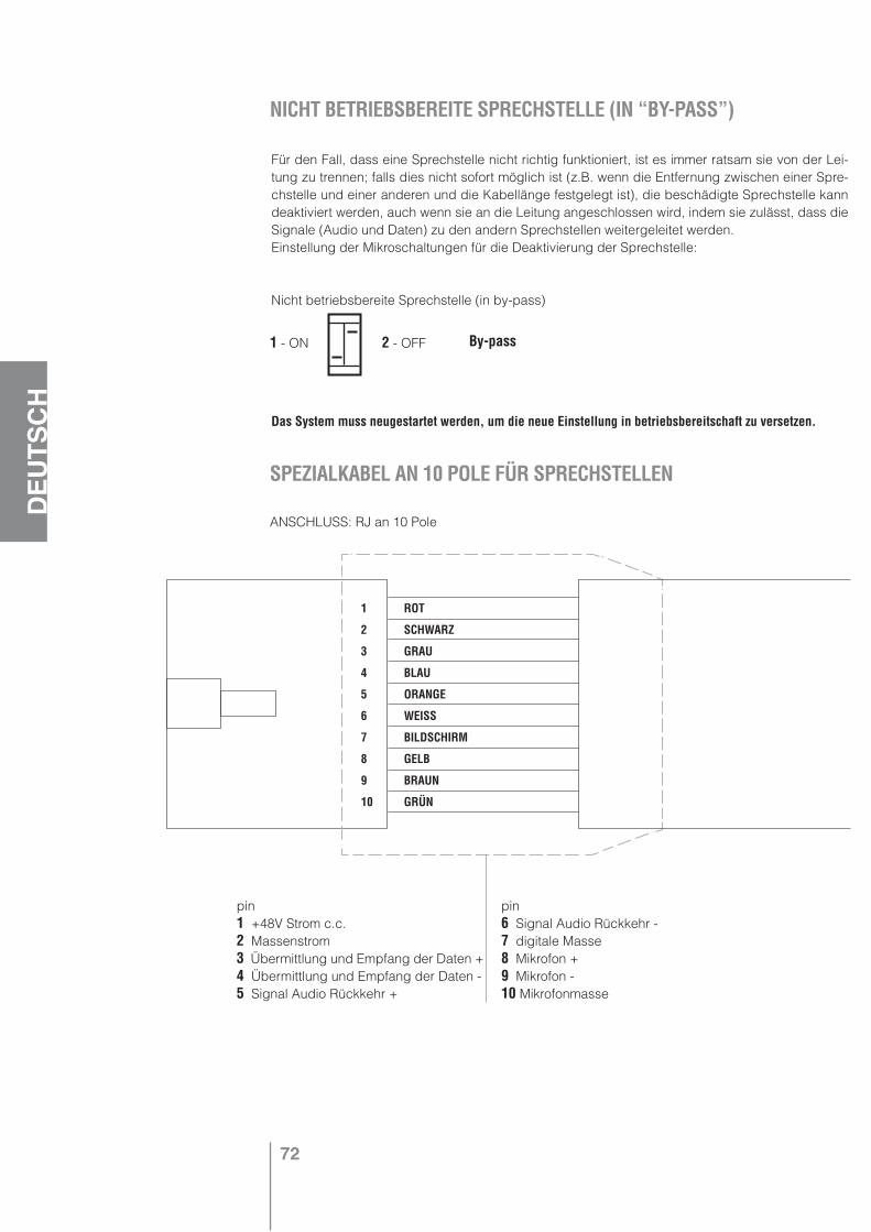
72
DEU
TSCH
Für den Fall, dass eine Sprechstelle nicht richtig funktioniert, ist es immer ratsam sie von der Lei-tung zu trennen; falls dies nicht sofort möglich ist (z.B. wenn die Entfernung zwischen einer Spre-chstelle und einer anderen und die Kabellänge festgelegt ist), die beschädigte Sprechstelle kann deaktiviert werden, auch wenn sie an die Leitung angeschlossen wird, indem sie zulässt, dass die Signale (Audio und Daten) zu den andern Sprechstellen weitergeleitet werden.Einstellung der Mikroschaltungen für die Deaktivierung der Sprechstelle:
Nicht betriebsbereite Sprechstelle (in by-pass)
Das System muss neugestartet werden, um die neue Einstellung in betriebsbereitschaft zu versetzen.
NICHT BETRIEBSBEREITE SPRECHSTELLE (IN “BY-PASS”)
By-pass
SPEZIALKABEL AN 10 POLE FÜR SPRECHSTELLEN
1 ROT
2 SCHWARZ
3 GRAU
4 BLAU
5 ORANGE
6 WEISS
7 BILDSCHIRM
8 GELB
9 BRAUN
10 GRÜN
ANSCHLUSS: RJ an 10 Pole
pin1 +48V Strom c.c.2 Massenstrom3 Übermittlung und Empfang der Daten + 4 Übermittlung und Empfang der Daten - 5 Signal Audio Rückkehr +
pin6 Signal Audio Rückkehr -7 digitale Masse8 Mikrofon +9 Mikrofon -10 Mikrofonmasse
1 - ON 2 - OFF
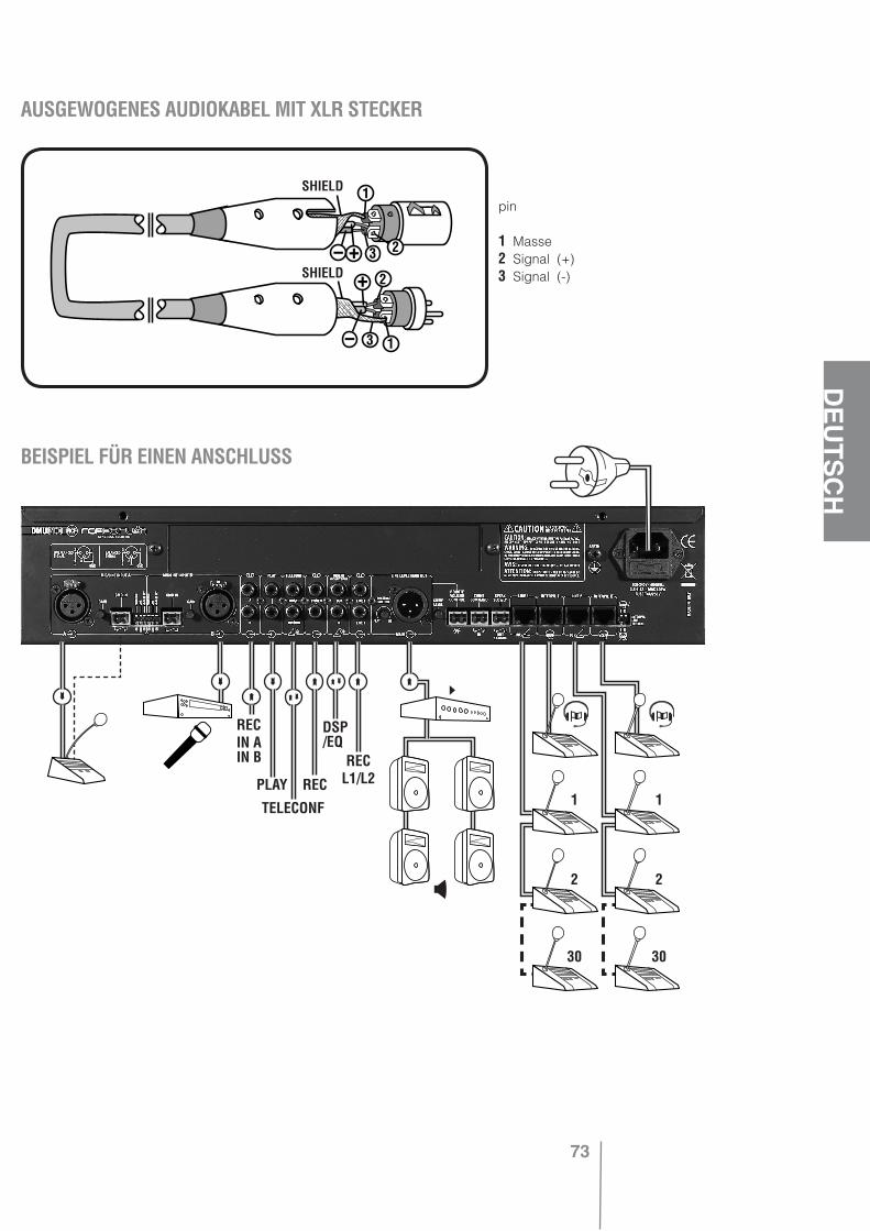
73
DEU
TSCH
AUSGEWOGENES AUDIOKABEL MIT XLR STECKERNICHT BETRIEBSBEREITE SPRECHSTELLE (IN “BY-PASS”)
SPEZIALKABEL AN 10 POLE FÜR SPRECHSTELLEN
pin
1 Masse2 Signal (+) 3 Signal (-)
BEISPIEL FÜR EINEN ANSCHLUSS
»
»»
»
»
»
»
»
»
»
RECIN AIN B
»
PLAY
TELECONF
REC
DSP/EQ
RECL1/L2
1 1
2 2
30 30
SHIELD
SHIELD
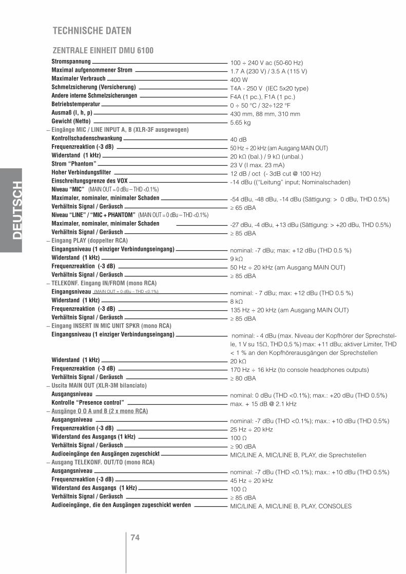
74
DEU
TSCH
Stromspannung Maximal aufgenommener Strom Maximaler Verbrauch Schmelzsicherung (Versicherung) Andere interne Schmelzsicherungen Betriebstemperatur Ausmaß (l, h, p) Gewicht (Netto) Eingänge MIC / LINE INPUT A, B (XLR-3F ausgewogen) Kontrollschadenschwankung Frequenzreaktion (-3 dB) Widerstand (1 kHz) Strom “Phantom” Hoher Verbindungsfilter Einschreitungsgrenze des VOX Niveau “MIC” (MAIN OUT = 0 dBu – THD <0.1%)Maximaler, nominaler, minimaler Schaden Verhältnis Signal / Geräusch Niveau “LINE” / “MIC + PHANTOM” (MAIN OUT = 0 dBu – THD <0.1%) Maximaler, nominaler, minimaler Schaden Verhältnis Signal / Geräusch Eingang PLAY (doppelter RCA)Eingangsniveau (1 einziger Verbindungseingang) Widerstand (1 kHz) Frequenzreaktion (-3 dB) Verhältnis Signal / Geräusch TELEKONF. Eingang IN/FROM (mono RCA)Eingangsniveau Widerstand (1 kHz) Frequenzreaktion (-3 dB) Verhältnis Signal / Geräusch Eingang INSERT IN MIC UNIT SPKR (mono RCA)Eingangsniveau (1 einziger Verbindungseingang)
Widerstand (1 kHz) Frequenzreaktion (-3 dB) Verhältnis Signal / Geräusch Uscita MAIN OUT (XLR-3M bilanciato)Ausgangsniveau Kontrolle “Presence control” Ausgänge O O A und B (2 x mono RCA)Ausgangsniveau Frequenzreaktion (-3 dB) Widerstand des Ausgangs (1 kHz) Verhältnis Signal / Geräusch Audioeingänge den Ausgängen zugeschickt Ausgang TELEKONF. OUT/TO (mono RCA) Ausgangsniveau Frequenzreaktion (-3 dB) Widerstand des Ausgangs (1 kHz) Verhältnis Signal / Geräusch Audioeingänge, die den Ausgängen zugeschickt werden
100 ÷ 240 V ac (50-60 Hz)1.7 A (230 V) / 3.5 A (115 V)400 WT4A - 250 V (IEC 5x20 type)F4A (1 pc.), F1A (1 pc.)0 ÷ 50 °C / 32÷122 °F430 mm, 88 mm, 310 mm5.65 kg
40 dB50 Hz ÷ 20 kHz (am Ausgang MAIN OUT)20 kΩ (bal.) / 9 kΩ (unbal.)23 V (I max. 23 mA)12 dB / oct (- 3dB cut @ 100 Hz)-14 dBu ((“Leitung” input; Nominalschaden)
-54 dBu, -48 dBu, -14 dBu (Sättigung: > 0 dBu, THD 0.5%)≥ 65 dBA
-27 dBu, -4 dBu, +13 dBu (Sättigung: > +20 dBu, THD 0.5%)≥ 85 dBA
nominal: -7 dBu; max: +12 dBu (THD 0.5 %)9 kΩ50 Hz ÷ 20 kHz (am Ausgang MAIN OUT)≥ 85 dBA
nominal: - 7 dBu; max: +12 dBu (THD 0.5 %)8 kΩ135 Hz ÷ 20 kHz (am Ausgang MAIN OUT)≥ 85 dBA
nominal: - 4 dBu (max. Niveau der Kopfhörer der Sprechstel-le, 1 V su 15Ω, THD 0,5 %) max: +11 dBu; aktiver Limiter, THD < 1 % an den Kopfhörerausgängen der Sprechstellen 20 kΩ170 Hz ÷ 16 kHz (to console headphones outputs)≥ 80 dBA
nominal: 0 dBu (THD <0.1%); max.: +20 dBu (THD 0.5%)max. + 15 dB @ 2.1 kHz
nominal: -7 dBu (THD <0.1%); max.: +10 dBu (THD 0.5%)25 Hz ÷ 20 kHz100 Ω≥ 90 dBAMIC/LINE A, MIC/LINE B, PLAY, die Sprechstellen
nominal: -7 dBu (THD <0.1%); max.: +10 dBu (THD 0.5%)45 Hz ÷ 20 kHz100 Ω≥ 85 dBAMIC/LINE A, MIC/LINE B, PLAY, CONSOLES
TECHNISCHE DATEN
ZENTRALE EINHEIT DMU 6100
(MAIN OUT = 0 dBu – THD <0.1%)
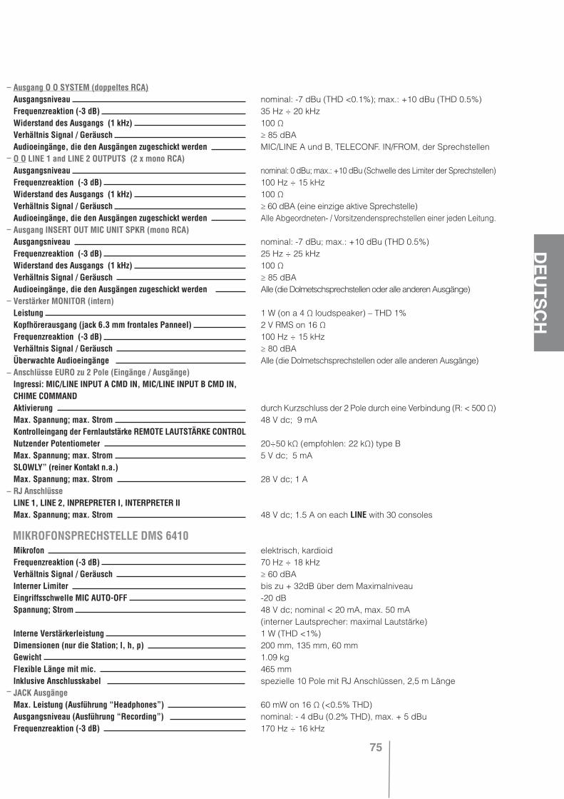
75
DEU
TSCH
MIKROFONSPRECHSTELLE DMS 6410
Ausgang O O SYSTEM (doppeltes RCA)Ausgangsniveau Frequenzreaktion (-3 dB) Widerstand des Ausgangs (1 kHz) Verhältnis Signal / Geräusch Audioeingänge, die den Ausgängen zugeschickt werden O O LINE 1 and LINE 2 OUTPUTS (2 x mono RCA)Ausgangsniveau Frequenzreaktion (-3 dB) Widerstand des Ausgangs (1 kHz) Verhältnis Signal / Geräusch Audioeingänge, die den Ausgängen zugeschickt werden Ausgang INSERT OUT MIC UNIT SPKR (mono RCA)Ausgangsniveau Frequenzreaktion (-3 dB) Widerstand des Ausgangs (1 kHz) Verhältnis Signal / Geräusch Audioeingänge, die den Ausgängen zugeschickt werden Verstärker MONITOR (intern)Leistung Kopfhörerausgang (jack 6.3 mm frontales Panneel) Frequenzreaktion (-3 dB) Verhältnis Signal / Geräusch Überwachte Audioeingänge Anschlüsse EURO zu 2 Pole (Eingänge / Ausgänge)Ingressi: MIC/LINE INPUT A CMD IN, MIC/LINE INPUT B CMD IN,CHIME COMMANDAktivierung Max. Spannung; max. Strom Kontrolleingang der Fernlautstärke REMOTE LAUTSTÄRKE CONTROLNutzender Potentiometer Max. Spannung; max. Strom SLOWLY” (reiner Kontakt n.a.)Max. Spannung; max. Strom RJ AnschlüsseLINE 1, LINE 2, INPREPRETER I, INTERPRETER IIMax. Spannung; max. Strom
Mikrofon Frequenzreaktion (-3 dB) Verhältnis Signal / Geräusch Interner Limiter Eingriffsschwelle MIC AUTO-OFF Spannung; Strom
Interne Verstärkerleistung Dimensionen (nur die Station; l, h, p) Gewicht Flexible Länge mit mic. Inklusive Anschlusskabel JACK Ausgänge Max. Leistung (Ausführung “Headphones”) Ausgangsniveau (Ausführung “Recording”) Frequenzreaktion (-3 dB)
nominal: -7 dBu (THD <0.1%); max.: +10 dBu (THD 0.5%)35 Hz ÷ 20 kHz100 Ω≥ 85 dBAMIC/LINE A und B, TELECONF. IN/FROM, der Sprechstellen
nominal: 0 dBu; max.: +10 dBu (Schwelle des Limiter der Sprechstellen)100 Hz ÷ 15 kHz100 Ω≥ 60 dBA (eine einzige aktive Sprechstelle)Alle Abgeordneten- / Vorsitzendensprechstellen einer jeden Leitung.
nominal: -7 dBu; max.: +10 dBu (THD 0.5%)25 Hz ÷ 25 kHz100 Ω≥ 85 dBAAlle (die Dolmetschsprechstellen oder alle anderen Ausgänge)
1 W (on a 4 Ω loudspeaker) – THD 1%2 V RMS on 16 Ω100 Hz ÷ 15 kHz≥ 80 dBAAlle (die Dolmetschsprechstellen oder alle anderen Ausgänge)
durch Kurzschluss der 2 Pole durch eine Verbindung (R: < 500 Ω)48 V dc; 9 mA
20÷50 kΩ (empfohlen: 22 kΩ) type B5 V dc; 5 mA
28 V dc; 1 A
48 V dc; 1.5 A on each LINE with 30 consoles
elektrisch, kardioid70 Hz ÷ 18 kHz≥ 60 dBAbis zu + 32dB über dem Maximalniveau-20 dB48 V dc; nominal < 20 mA, max. 50 mA (interner Lautsprecher: maximal Lautstärke)1 W (THD <1%)200 mm, 135 mm, 60 mm1.09 kg465 mmspezielle 10 Pole mit RJ Anschlüssen, 2,5 m Länge
60 mW on 16 Ω (<0.5% THD)nominal: - 4 dBu (0.2% THD), max. + 5 dBu170 Hz ÷ 16 kHz
the rules of soundRCF SpA: Via Raffaello, 13 - 42010 Reggio Emilia > Italytel. +39 0522 274411 - fax +39 0522 274484 - e-mail: [email protected]
Salvo eventuali errori ed omissioni.RCF S.p.A. si riserva il diritto di apportare modifiche senza preavviso.
Except possible errors and omissions.RCF S.p.A. reserves the right to make modifications without prior notice.
10307102E